preparing srm cards for communications · chapter 5-1 cisco mgx 8800/8900 series software...
TRANSCRIPT
Cisco MOL-13643-01
C H A P T E R 5
Preparing SRM Cards for CommunicationsTo prepare SRM cards for communication, you need to know which SRM features will be used. Because SRM cards operate as extensions of the PXM cards, they are initialized when you initialize the PXM card, so the initialization procedure required for most service modules is not required for SRM. SRM cards provide the following features:
• 1:N redundancy support for select service modules
• Bulk distribution
• Bit error rate testing (BERT)
Note For more information on BERT, see the “Managing Bit Error Rate Tests” section of Chapter 9, “Switch Operating Procedures.”
SRM cards can operate as standalone cards or as redundant cards. As described in the Cisco MGX 8800/8900 Hardware Installation Guide, Releases 2 - 5.2, MGX switches are preconfigured for SRM card redundancy, and this redundancy must match the configuration (standalone or redundant) of the PXM card. After installation, no configuration is required to establish a standalone or redundant SRM configuration.
When installed, SRM cards automatically support 1:N redundancy for 8-port service modules with T1 or E1 interfaces as listed in the Cisco MGX 8800/8900 Hardware Installation Guide, Releases 2 - 5.2. To configure 1:N redundancy for service modules, refer to Chapter 4, “Preparing Service Modules for Communication.”
Tip If you are not using the SRM bulk distribution feature, you can skip reading the rest of this chapter, which describes how to configure bulk distribution on SRM cards.
The bulk distribution feature enables the SRM to receive T1 and E1 traffic that has been multiplexed into a T3 or OC-3 line and route that traffic to the appropriate service module for processing. T1 traffic is supported on T3 or OC3/SDH SRM interfaces. E1 traffic is only supported on SDH SRM interfaces. Responses are sent back through the SRM to the equipment at the other end of the T3 or OC-3 line.
When bulk distribution is used, you must bring up and optionally configure the T3 or OC-3 lines on SRM back cards. For redundant SRM cards with SONET/SDH interfaces, you have the option of configuring line redundancy for the attached OC-3 lines. For all cards that use bulk distribution services, you must configure links, which are logical mappings between the lines on the service modules and the channels embedded in the T3 or OC-3 lines connected to a SRM.
When planning for bulk distribution, consider the following guidelines:
5-1GX 8800/8900 Series Software Configuration Guide
Chapter 5 Preparing SRM Cards for CommunicationsConfiguration Quickstart for Bulk Distribution on SRMs Configured for SONET/SDH
• Bulk distribution works with T1 and E1 service modules. Refer to the Cisco MGX 8800/8900 Hardware Installation Guide, Releases 2 - 5.2, to see which service modules support bulk distribution.
• The Cisco MGX 8800/8900 Hardware Installation Guide, Releases 2 - 5.2, describes the physical planning requirements for installing hardware to support bulk distribution. If these requirements are not met, bulk distribution will not work properly.
• When a service module is configured to use bulk distribution, this service is applied to all lines on the service module and no back cards are required.
• A standalone or redundant SRM-3T3/C configuration can support up to 84 T1 channels, each of which supports a service module T1 port. Where supported, up to 12 slots can be used for bulk distribution, assuming the following conditions:
– If any line on a service module is configured for bulk distribution, then the entire service module becomes dedicated to bulk distribution.
– The nth spare card in a 1:N sparing group must not have any lines configured on it at all.
• A standalone or redundant SRME/B with a BNC-3T3-M back card can support up to 84 T1 channels, each of which supports a service module T1 port. These channels can be divided between up to 11 card slots per bay.
• The maximum number of E1 channels is 63, each of which supports a service module E1 port. These channels can be divided between up to 8 card slots per bay.
• A standalone or redundant SRME or SRME/B SONET/SDH configuration can support up to 84 T1 channels or 63 E1 channels per bay, and these channels can be divided between all 12 card slots in the bay.
This chapter provides quickstart procedures for configuring SRM cards, and it provides the following additional procedures that describe the steps in the quickstart procedures:
• Setting Up SRM Lines
• Establishing Redundancy Between SONET/SDH Lines with APS
• Linking Service Module Lines to SRM Channels, VTs, or VCs
Note SRM configuration is done from the PXM card. The software does not allow you to use the cc command switch to an SRM.
Note The MGX 8950 does not support SRM cards.
Configuration Quickstart for Bulk Distribution on SRMs Configured for SONET/SDH
The quickstart procedure in this section summarizes how to configure bulk distribution on SRME and on SRME/B cards configured for SONET/SDH interfaces. This procedure is a quick reference for those who already have configured MGX 8850 and Cisco MGX 8830 switches.
5-2Cisco MGX 8800/8900 Series Software Configuration Guide
OL-13643-01
Chapter 5 Preparing SRM Cards for CommunicationsConfiguration Quickstart for Bulk Distribution on SRMs Configured for T3 Interfaces
Configuration Quickstart for Bulk Distribution on SRMs Configured for T3 Interfaces
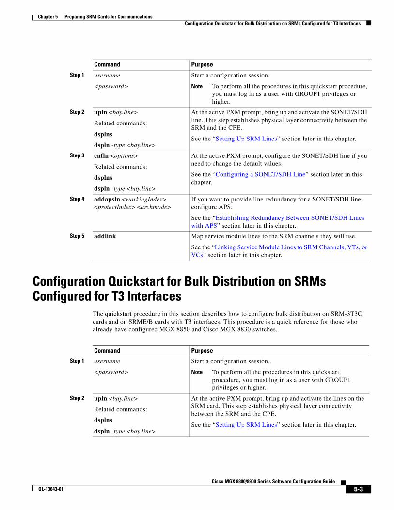
The quickstart procedure in this section describes how to configure bulk distribution on SRM-3T3C cards and on SRME/B cards with T3 interfaces. This procedure is a quick reference for those who already have configured MGX 8850 and Cisco MGX 8830 switches.
Command Purpose
Step 1 username
<password>
Start a configuration session.
Note To perform all the procedures in this quickstart procedure, you must log in as a user with GROUP1 privileges or higher.
Step 2 upln <bay.line>
Related commands:
dsplns
dspln -type <bay.line>
At the active PXM prompt, bring up and activate the SONET/SDH line. This step establishes physical layer connectivity between the SRM and the CPE.
See the “Setting Up SRM Lines” section later in this chapter.
Step 3 cnfln <options>
Related commands:
dsplns
dspln -type <bay.line>
At the active PXM prompt, configure the SONET/SDH line if you need to change the default values.
See the “Configuring a SONET/SDH Line” section later in this chapter.
Step 4 addapsln <workingIndex> <protectIndex> <archmode>
If you want to provide line redundancy for a SONET/SDH line, configure APS.
See the “Establishing Redundancy Between SONET/SDH Lines with APS” section later in this chapter.
Step 5 addlink Map service module lines to the SRM channels they will use.
See the “Linking Service Module Lines to SRM Channels, VTs, or VCs” section later in this chapter.
Command Purpose
Step 1 username
<password>
Start a configuration session.
Note To perform all the procedures in this quickstart procedure, you must log in as a user with GROUP1 privileges or higher.
Step 2 upln <bay.line>
Related commands:
dsplns
dspln -type <bay.line>
At the active PXM prompt, bring up and activate the lines on the SRM card. This step establishes physical layer connectivity between the SRM and the CPE.
See the “Setting Up SRM Lines” section later in this chapter.
5-3Cisco MGX 8800/8900 Series Software Configuration Guide
OL-13643-01
Chapter 5 Preparing SRM Cards for CommunicationsSetting Up SRM Lines
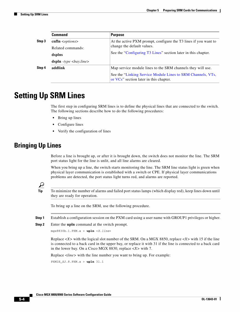
Setting Up SRM LinesThe first step in configuring SRM lines is to define the physical lines that are connected to the switch. The following sections describe how to do the following procedures:
• Bring up lines
• Configure lines
• Verify the configuration of lines
Bringing Up LinesBefore a line is brought up, or after it is brought down, the switch does not monitor the line. The SRM port status light for the line is unlit, and all line alarms are cleared.
When you bring up a line, the switch starts monitoring the line. The SRM line status light is green when physical layer communication is established with a switch or CPE. If physical layer communications problems are detected, the port status light turns red, and alarms are reported.
Tip To minimize the number of alarms and failed port status lamps (which display red), keep lines down until they are ready for operation.
To bring up a line on the SRM, use the following procedure.
Step 1 Establish a configuration session on the PXM card using a user name with GROUP1 privileges or higher.
Step 2 Enter the upln command at the switch prompt.
mgx8830b.1.PXM.a > upln <X.line>
Replace <X> with the logical slot number of the SRM. On a MGX 8850, replace <X> with 15 if the line is connected to a back card in the upper bay, or replace it with 31 if the line is connected to a back card in the lower bay. On a Cisco MGX 8830, replace <X> with 7.
Replace <line> with the line number you want to bring up. For example:
PXM1E_SJ.8.PXM.a > upln 31.1
Step 3 cnfln <options>
Related commands:
dsplns
dspln -type <bay.line>
At the active PXM prompt, configure the T3 lines if you want to change the default values.
See the “Configuring T3 Lines” section later in this chapter.
Step 4 addlink Map service module lines to the SRM channels they will use.
See the “Linking Service Module Lines to SRM Channels, VTs, or VCs” section later in this chapter.
Command Purpose
5-4Cisco MGX 8800/8900 Series Software Configuration Guide
OL-13643-01
Chapter 5 Preparing SRM Cards for CommunicationsSetting Up SRM Lines
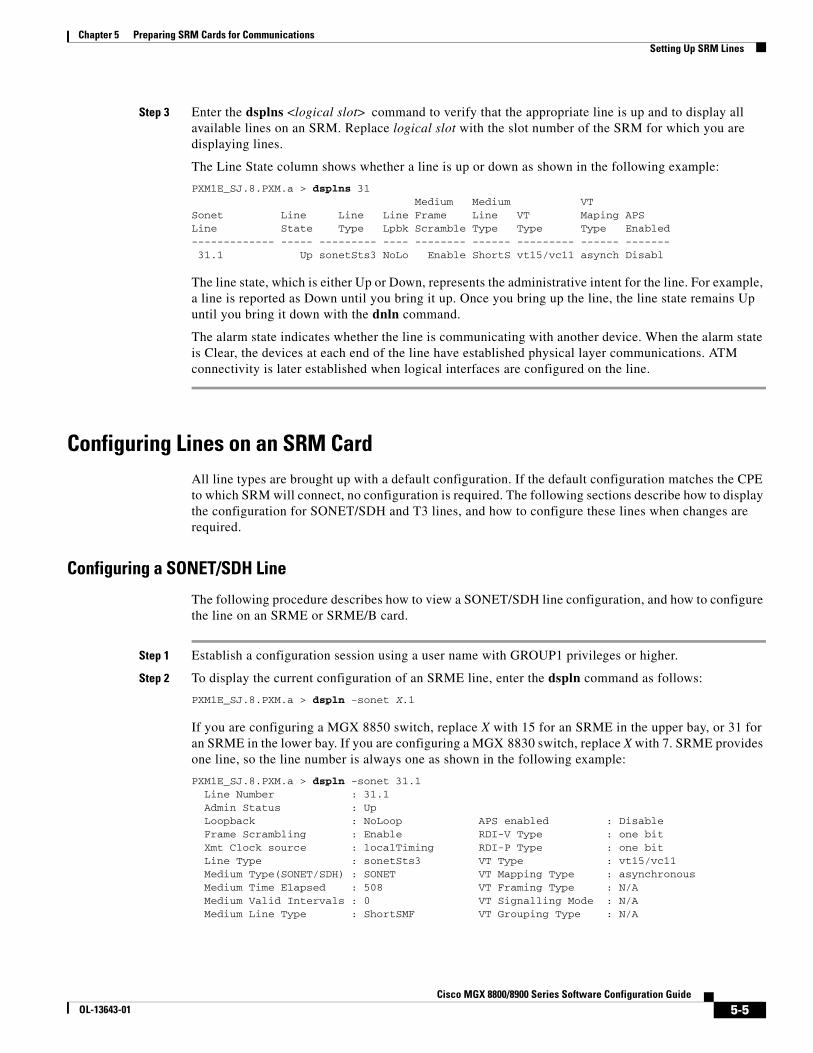
Step 3 Enter the dsplns <logical slot> command to verify that the appropriate line is up and to display all available lines on an SRM. Replace logical slot with the slot number of the SRM for which you are displaying lines.
The Line State column shows whether a line is up or down as shown in the following example:
PXM1E_SJ.8.PXM.a > dsplns 31 Medium Medium VTSonet Line Line Line Frame Line VT Maping APSLine State Type Lpbk Scramble Type Type Type Enabled------------- ----- --------- ---- -------- ------ --------- ------ ------- 31.1 Up sonetSts3 NoLo Enable ShortS vt15/vc11 asynch Disabl
The line state, which is either Up or Down, represents the administrative intent for the line. For example, a line is reported as Down until you bring it up. Once you bring up the line, the line state remains Up until you bring it down with the dnln command.
The alarm state indicates whether the line is communicating with another device. When the alarm state is Clear, the devices at each end of the line have established physical layer communications. ATM connectivity is later established when logical interfaces are configured on the line.
Configuring Lines on an SRM CardAll line types are brought up with a default configuration. If the default configuration matches the CPE to which SRM will connect, no configuration is required. The following sections describe how to display the configuration for SONET/SDH and T3 lines, and how to configure these lines when changes are required.
Configuring a SONET/SDH Line
The following procedure describes how to view a SONET/SDH line configuration, and how to configure the line on an SRME or SRME/B card.
Step 1 Establish a configuration session using a user name with GROUP1 privileges or higher.
Step 2 To display the current configuration of an SRME line, enter the dspln command as follows:
PXM1E_SJ.8.PXM.a > dspln -sonet X.1
If you are configuring a MGX 8850 switch, replace X with 15 for an SRME in the upper bay, or 31 for an SRME in the lower bay. If you are configuring a MGX 8830 switch, replace X with 7. SRME provides one line, so the line number is always one as shown in the following example:
PXM1E_SJ.8.PXM.a > dspln -sonet 31.1 Line Number : 31.1 Admin Status : Up Loopback : NoLoop APS enabled : Disable Frame Scrambling : Enable RDI-V Type : one bit Xmt Clock source : localTiming RDI-P Type : one bit Line Type : sonetSts3 VT Type : vt15/vc11 Medium Type(SONET/SDH) : SONET VT Mapping Type : asynchronous Medium Time Elapsed : 508 VT Framing Type : N/A Medium Valid Intervals : 0 VT Signalling Mode : N/A Medium Line Type : ShortSMF VT Grouping Type : N/A
5-5Cisco MGX 8800/8900 Series Software Configuration Guide
OL-13643-01
Chapter 5 Preparing SRM Cards for CommunicationsSetting Up SRM Lines
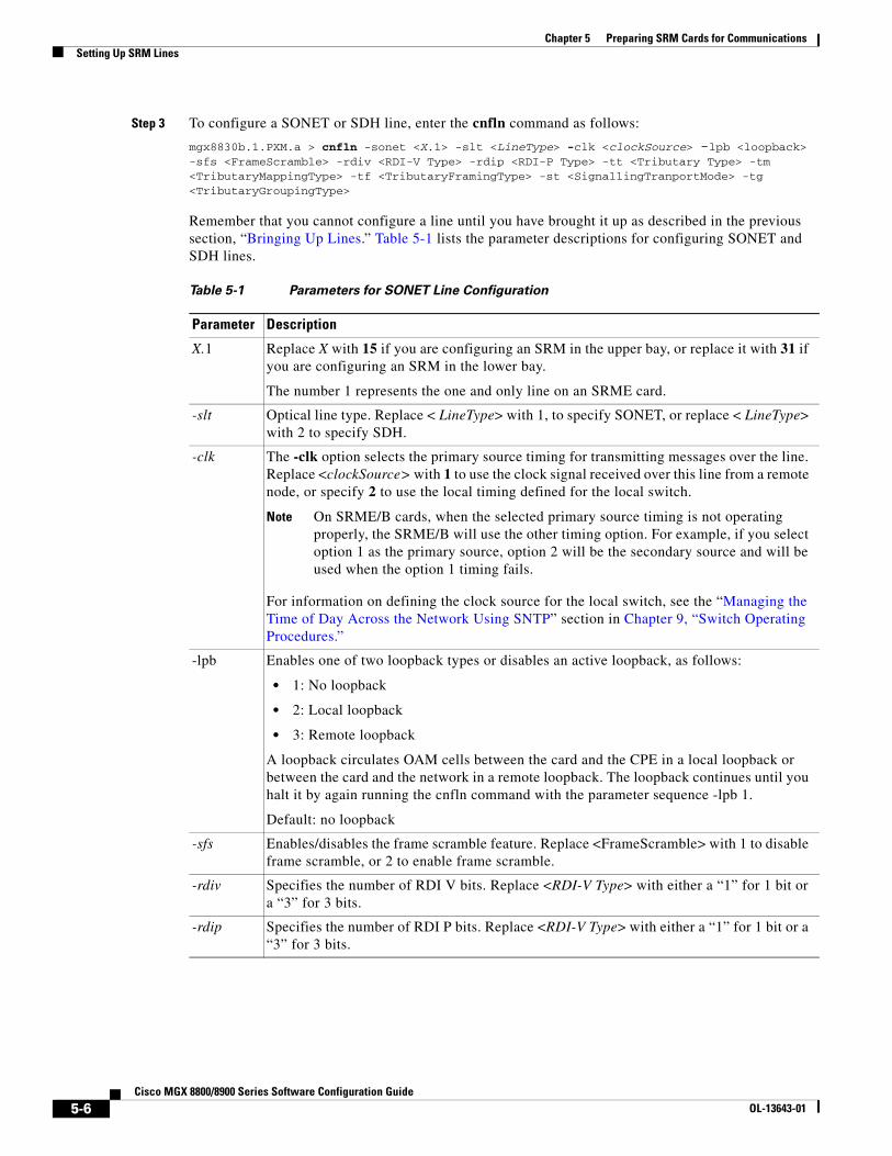
Step 3 To configure a SONET or SDH line, enter the cnfln command as follows:
mgx8830b.1.PXM.a > cnfln -sonet <X.1> -slt <LineType> -clk <clockSource> -lpb <loopback> -sfs <FrameScramble> -rdiv <RDI-V Type> -rdip <RDI-P Type> -tt <Tributary Type> -tm <TributaryMappingType> -tf <TributaryFramingType> -st <SignallingTranportMode> -tg <TributaryGroupingType>
Remember that you cannot configure a line until you have brought it up as described in the previous section, “Bringing Up Lines.” Table 5-1 lists the parameter descriptions for configuring SONET and SDH lines.
Table 5-1 Parameters for SONET Line Configuration
Parameter Description
X.1 Replace X with 15 if you are configuring an SRM in the upper bay, or replace it with 31 if you are configuring an SRM in the lower bay.
The number 1 represents the one and only line on an SRME card.
-slt Optical line type. Replace < LineType> with 1, to specify SONET, or replace < LineType> with 2 to specify SDH.
-clk The -clk option selects the primary source timing for transmitting messages over the line. Replace <clockSource> with 1 to use the clock signal received over this line from a remote node, or specify 2 to use the local timing defined for the local switch.
Note On SRME/B cards, when the selected primary source timing is not operating properly, the SRME/B will use the other timing option. For example, if you select option 1 as the primary source, option 2 will be the secondary source and will be used when the option 1 timing fails.
For information on defining the clock source for the local switch, see the “Managing the Time of Day Across the Network Using SNTP” section in Chapter 9, “Switch Operating Procedures.”
-lpb Enables one of two loopback types or disables an active loopback, as follows:
• 1: No loopback
• 2: Local loopback
• 3: Remote loopback
A loopback circulates OAM cells between the card and the CPE in a local loopback or between the card and the network in a remote loopback. The loopback continues until you halt it by again running the cnfln command with the parameter sequence -lpb 1.
Default: no loopback
-sfs Enables/disables the frame scramble feature. Replace <FrameScramble> with 1 to disable frame scramble, or 2 to enable frame scramble.
-rdiv Specifies the number of RDI V bits. Replace <RDI-V Type> with either a “1” for 1 bit or a “3” for 3 bits.
-rdip Specifies the number of RDI P bits. Replace <RDI-V Type> with either a “1” for 1 bit or a “3” for 3 bits.
5-6Cisco MGX 8800/8900 Series Software Configuration Guide
OL-13643-01
Chapter 5 Preparing SRM Cards for CommunicationsSetting Up SRM Lines
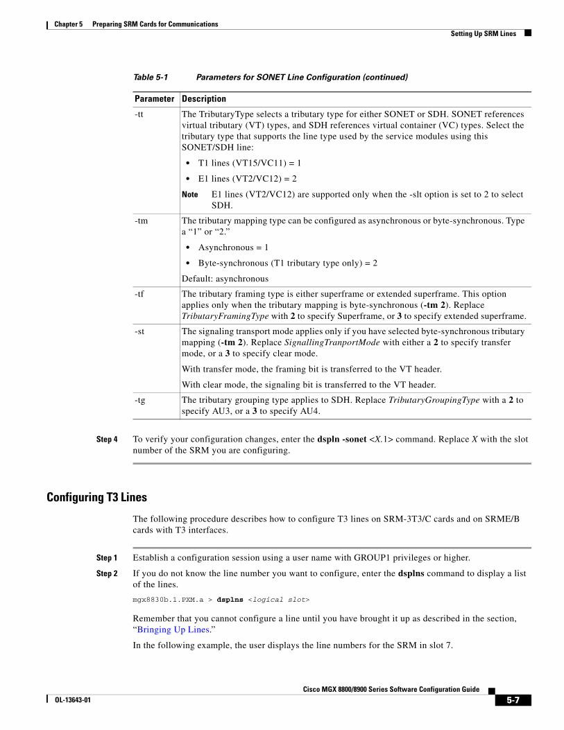
Step 4 To verify your configuration changes, enter the dspln -sonet <X.1> command. Replace X with the slot number of the SRM you are configuring.
Configuring T3 Lines
The following procedure describes how to configure T3 lines on SRM-3T3/C cards and on SRME/B cards with T3 interfaces.
Step 1 Establish a configuration session using a user name with GROUP1 privileges or higher.
Step 2 If you do not know the line number you want to configure, enter the dsplns command to display a list of the lines.
mgx8830b.1.PXM.a > dsplns <logical slot>
Remember that you cannot configure a line until you have brought it up as described in the section, “Bringing Up Lines.”
In the following example, the user displays the line numbers for the SRM in slot 7.
-tt The TributaryType selects a tributary type for either SONET or SDH. SONET references virtual tributary (VT) types, and SDH references virtual container (VC) types. Select the tributary type that supports the line type used by the service modules using this SONET/SDH line:
• T1 lines (VT15/VC11) = 1
• E1 lines (VT2/VC12) = 2
Note E1 lines (VT2/VC12) are supported only when the -slt option is set to 2 to select SDH.
-tm The tributary mapping type can be configured as asynchronous or byte-synchronous. Type a “1” or “2.”
• Asynchronous = 1
• Byte-synchronous (T1 tributary type only) = 2
Default: asynchronous
-tf The tributary framing type is either superframe or extended superframe. This option applies only when the tributary mapping is byte-synchronous (-tm 2). Replace TributaryFramingType with 2 to specify Superframe, or 3 to specify extended superframe.
-st The signaling transport mode applies only if you have selected byte-synchronous tributary mapping (-tm 2). Replace SignallingTranportMode with either a 2 to specify transfer mode, or a 3 to specify clear mode.
With transfer mode, the framing bit is transferred to the VT header.
With clear mode, the signaling bit is transferred to the VT header.
-tg The tributary grouping type applies to SDH. Replace TributaryGroupingType with a 2 to specify AU3, or a 3 to specify AU4.
Table 5-1 Parameters for SONET Line Configuration (continued)
Parameter Description
5-7Cisco MGX 8800/8900 Series Software Configuration Guide
OL-13643-01
Chapter 5 Preparing SRM Cards for CommunicationsSetting Up SRM Lines
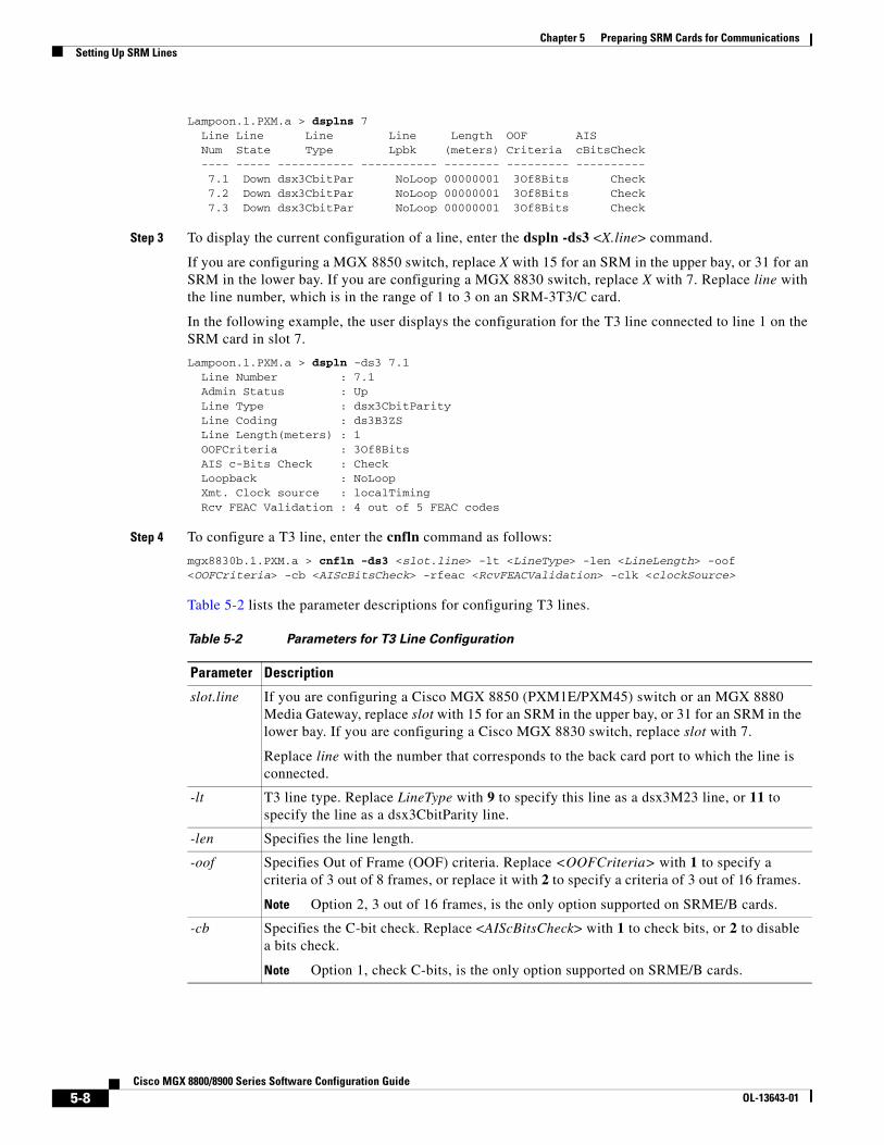
Lampoon.1.PXM.a > dsplns 7 Line Line Line Line Length OOF AIS Num State Type Lpbk (meters) Criteria cBitsCheck ---- ----- ----------- ----------- -------- --------- ---------- 7.1 Down dsx3CbitPar NoLoop 00000001 3Of8Bits Check 7.2 Down dsx3CbitPar NoLoop 00000001 3Of8Bits Check 7.3 Down dsx3CbitPar NoLoop 00000001 3Of8Bits Check
Step 3 To display the current configuration of a line, enter the dspln -ds3 <X.line> command.
If you are configuring a MGX 8850 switch, replace X with 15 for an SRM in the upper bay, or 31 for an SRM in the lower bay. If you are configuring a MGX 8830 switch, replace X with 7. Replace line with the line number, which is in the range of 1 to 3 on an SRM-3T3/C card.
In the following example, the user displays the configuration for the T3 line connected to line 1 on the SRM card in slot 7.
Lampoon.1.PXM.a > dspln -ds3 7.1 Line Number : 7.1 Admin Status : Up Line Type : dsx3CbitParity Line Coding : ds3B3ZS Line Length(meters) : 1 OOFCriteria : 3Of8Bits AIS c-Bits Check : Check Loopback : NoLoop Xmt. Clock source : localTiming Rcv FEAC Validation : 4 out of 5 FEAC codes
Step 4 To configure a T3 line, enter the cnfln command as follows:
mgx8830b.1.PXM.a > cnfln -ds3 <slot.line> -lt <LineType> -len <LineLength> -oof <OOFCriteria> -cb <AIScBitsCheck> -rfeac <RcvFEACValidation> -clk <clockSource>
Table 5-2 lists the parameter descriptions for configuring T3 lines.
Table 5-2 Parameters for T3 Line Configuration
Parameter Description
slot.line If you are configuring a Cisco MGX 8850 (PXM1E/PXM45) switch or an MGX 8880 Media Gateway, replace slot with 15 for an SRM in the upper bay, or 31 for an SRM in the lower bay. If you are configuring a Cisco MGX 8830 switch, replace slot with 7.
Replace line with the number that corresponds to the back card port to which the line is connected.
-lt T3 line type. Replace LineType with 9 to specify this line as a dsx3M23 line, or 11 to specify the line as a dsx3CbitParity line.
-len Specifies the line length.
-oof Specifies Out of Frame (OOF) criteria. Replace <OOFCriteria> with 1 to specify a criteria of 3 out of 8 frames, or replace it with 2 to specify a criteria of 3 out of 16 frames.
Note Option 2, 3 out of 16 frames, is the only option supported on SRME/B cards.
-cb Specifies the C-bit check. Replace <AIScBitsCheck> with 1 to check bits, or 2 to disable a bits check.
Note Option 1, check C-bits, is the only option supported on SRME/B cards.
5-8Cisco MGX 8800/8900 Series Software Configuration Guide
OL-13643-01
Chapter 5 Preparing SRM Cards for CommunicationsEstablishing Redundancy Between SONET/SDH Lines with APS
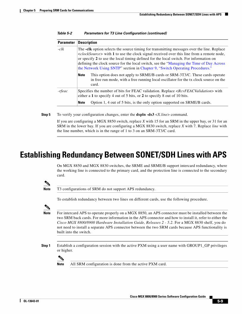
Step 5 To verify your configuration changes, enter the dspln -ds3 <X.line> command.
If you are configuring a MGX 8850 switch, replace X with 15 for an SRM in the upper bay, or 31 for an SRM in the lower bay. If you are configuring a MGX 8830 switch, replace X with 7. Replace line with the line number, which is in the range of 1 to 3 on an SRM-3T3/C card.
Establishing Redundancy Between SONET/SDH Lines with APS On MGX 8850 and MGX 8830 switches, the SRME and SRME/B support intercard redundancy, where the working line is connected to the primary card, and the protection line is connected to the secondary card.
Note T3 configurations of SRM do not support APS redundancy.
To establish redundancy between two lines on different cards, use the following procedure.
Note For intercard APS to operate properly on a MGX 8850, an APS connector must be installed between the two SRM back cards. For more information in the APS connector and how to install it, refer to either the Cisco MGX 8800/8900 Hardware Installation Guide, Releases 2 - 5.2. For a MGX 8830 shelf, you do not need to install a separate APS connector between the two SRM cards because APS functionality is built into the switch.
Step 1 Establish a configuration session with the active PXM using a user name with GROUP1_GP privileges or higher.
Note All SRM configuration is done from the active PXM card.
-clk The -clk option selects the source timing for transmitting messages over the line. Replace <clockSource> with 1 to use the clock signal received over this line from a remote node, or specify 2 to use the local timing defined for the local switch. For information on defining the clock source for the local switch, see the “Managing the Time of Day Across the Network Using SNTP” section in Chapter 9, “Switch Operating Procedures.”
Note This option does not apply to SRME/B cards or SRM-3T3/C. These cards operate in free run mode, with a free running local oscillator for the tx clock source on the card.
-rfeac Specifies the number of bits for FEAC validation. Replace <RcvFEACValidation> with either a 1 to specify 4 out of 5 bits, or 2 to specify 8 out of 10 bits.
Note Option 1, 4 out of 5 bits, is the only option supported on SRME/B cards.
Table 5-2 Parameters for T3 Line Configuration (continued)
Parameter Description
5-9Cisco MGX 8800/8900 Series Software Configuration Guide
OL-13643-01
Chapter 5 Preparing SRM Cards for CommunicationsEstablishing Redundancy Between SONET/SDH Lines with APS
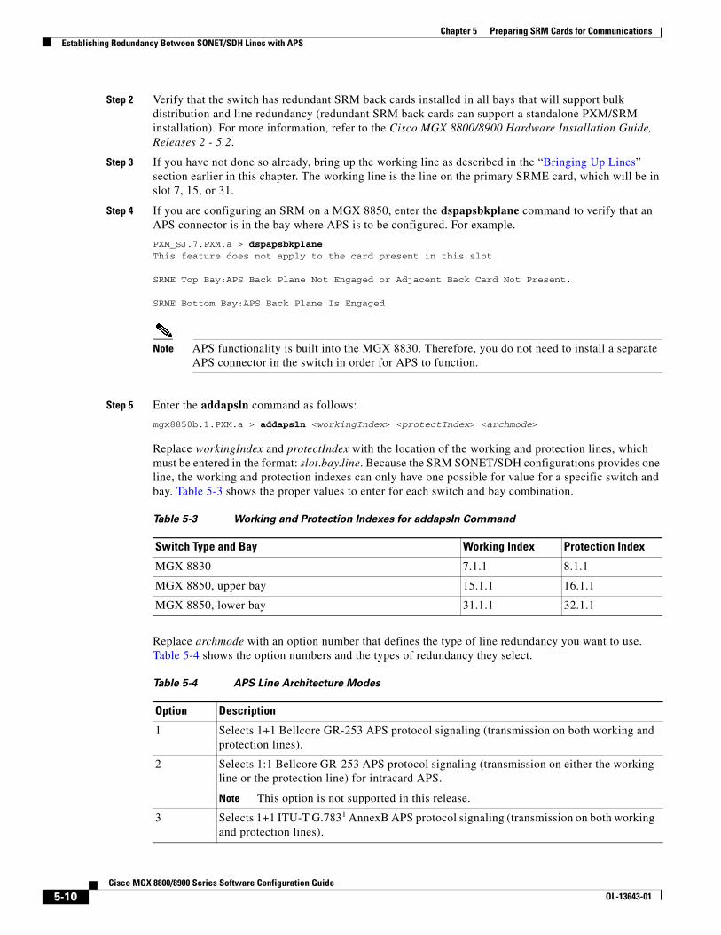
Step 2 Verify that the switch has redundant SRM back cards installed in all bays that will support bulk distribution and line redundancy (redundant SRM back cards can support a standalone PXM/SRM installation). For more information, refer to the Cisco MGX 8800/8900 Hardware Installation Guide, Releases 2 - 5.2.
Step 3 If you have not done so already, bring up the working line as described in the “Bringing Up Lines” section earlier in this chapter. The working line is the line on the primary SRME card, which will be in slot 7, 15, or 31.
Step 4 If you are configuring an SRM on a MGX 8850, enter the dspapsbkplane command to verify that an APS connector is in the bay where APS is to be configured. For example.
PXM_SJ.7.PXM.a > dspapsbkplaneThis feature does not apply to the card present in this slot
SRME Top Bay:APS Back Plane Not Engaged or Adjacent Back Card Not Present.
SRME Bottom Bay:APS Back Plane Is Engaged
Note APS functionality is built into the MGX 8830. Therefore, you do not need to install a separate APS connector in the switch in order for APS to function.
Step 5 Enter the addapsln command as follows:
mgx8850b.1.PXM.a > addapsln <workingIndex> <protectIndex> <archmode>
Replace workingIndex and protectIndex with the location of the working and protection lines, which must be entered in the format: slot.bay.line. Because the SRM SONET/SDH configurations provides one line, the working and protection indexes can only have one possible for value for a specific switch and bay. Table 5-3 shows the proper values to enter for each switch and bay combination.
Replace archmode with an option number that defines the type of line redundancy you want to use. Table 5-4 shows the option numbers and the types of redundancy they select.
Table 5-3 Working and Protection Indexes for addapsln Command
Switch Type and Bay Working Index Protection Index
MGX 8830 7.1.1 8.1.1
MGX 8850, upper bay 15.1.1 16.1.1
MGX 8850, lower bay 31.1.1 32.1.1
Table 5-4 APS Line Architecture Modes
Option Description
1 Selects 1+1 Bellcore GR-253 APS protocol signaling (transmission on both working and protection lines).
2 Selects 1:1 Bellcore GR-253 APS protocol signaling (transmission on either the working line or the protection line) for intracard APS.
Note This option is not supported in this release.
3 Selects 1+1 ITU-T G.7831 AnnexB APS protocol signaling (transmission on both working and protection lines).
5-10Cisco MGX 8800/8900 Series Software Configuration Guide
OL-13643-01
Chapter 5 Preparing SRM Cards for CommunicationsEstablishing Redundancy Between SONET/SDH Lines with APS
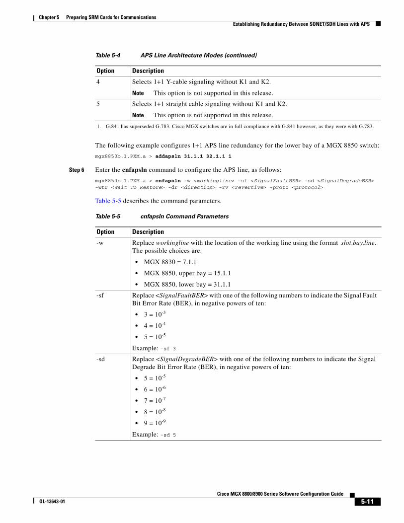
The following example configures 1+1 APS line redundancy for the lower bay of a MGX 8850 switch:
mgx8850b.1.PXM.a > addapsln 31.1.1 32.1.1 1
Step 6 Enter the cnfapsln command to configure the APS line, as follows:
mgx8850b.1.PXM.a > cnfapsln -w <workingline> -sf <SignalFaultBER> -sd <SignalDegradeBER> -wtr <Wait To Restore> -dr <direction> -rv <revertive> -proto <protocol>
Table 5-5 describes the command parameters.
4 Selects 1+1 Y-cable signaling without K1 and K2.
Note This option is not supported in this release.
5 Selects 1+1 straight cable signaling without K1 and K2.
Note This option is not supported in this release.
1. G.841 has superseded G.783. Cisco MGX switches are in full compliance with G.841 however, as they were with G.783.
Table 5-4 APS Line Architecture Modes (continued)
Option Description
Table 5-5 cnfapsln Command Parameters
Option Description
-w Replace workingline with the location of the working line using the format slot.bay.line. The possible choices are:
• MGX 8830 = 7.1.1
• MGX 8850, upper bay = 15.1.1
• MGX 8850, lower bay = 31.1.1
-sf Replace <SignalFaultBER> with one of the following numbers to indicate the Signal Fault Bit Error Rate (BER), in negative powers of ten:
• 3 = 10-3
• 4 = 10-4
• 5 = 10-5
Example: -sf 3
-sd Replace <SignalDegradeBER> with one of the following numbers to indicate the Signal Degrade Bit Error Rate (BER), in negative powers of ten:
• 5 = 10-5
• 6 = 10-6
• 7 = 10-7
• 8 = 10-8
• 9 = 10-9
Example: -sd 5
5-11Cisco MGX 8800/8900 Series Software Configuration Guide
OL-13643-01
Chapter 5 Preparing SRM Cards for CommunicationsLinking Service Module Lines to SRM Channels, VTs, or VCs
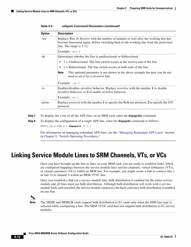
Step 7 To display the a list of all the APS lines on an SRM card, enter the dspapslns command.
Step 8 To display the configuration of a single APS line, enter the dspapsln command as follows:
M8850_LA.8.PXM.a > dspapsln 15.1.1
For information on managing redundant APS lines, see the “Managing Redundant APS Lines” section in Chapter 9, “Switch Operating Procedures.”
Linking Service Module Lines to SRM Channels, VTs, or VCsOnce you have brought up the line or lines on your SRM card, you are ready to establish links, which are configured mappings between the service module lines and the channels, virtual tributaries (VTs), or virtual containers (VCs) within an SRM line. For example, you might create a link to connect line 1 in slot 14 to channel 5 within an SRM-3T3/C line.
Once you establish a link for a service module line, bulk distribution is enabled for the entire service module and all lines must use bulk distribution. Although bulk distribution will work with a service module back card installed, the service module cannot use the back card once bulk distribution is enabled on any line.
Note The SRME and SRME/B cards support bulk distribution to E1 cards only when the SDH line type is selected while configuring a line. The SRM-3T3/C card does not support bulk distribution to E1 service modules.
-wtr Replace Wait To Restore with the number of minutes to wait after the working line has become functional again, before switching back to the working line from the protection line. The range is 5-12.
Example: -wtr 5
-dr Determines whether the line is unidirectional or bidirectional.
• 1 = Unidirectional. The line switch occurs at the receive end of the line.
• 2 = Bidirectional. The line switch occurs at both ends of the line.
Note This optional parameter is not shown in the above example because you do not need to set it for a revertive line.
Example: -dr 2
-rv Enables/disables revertive behavior. Replace revertive with the number 1 to disable revertive behavior, or 2 to enable revertive behavior.
Example: -rv 1
-proto Replace protocol with the number 1 to specify the Bellcore protocol, 2 to specify the ITU protocol.
Table 5-5 cnfapsln Command Parameters (continued)
Option Description
5-12Cisco MGX 8800/8900 Series Software Configuration Guide
OL-13643-01
Chapter 5 Preparing SRM Cards for CommunicationsLinking Service Module Lines to SRM Channels, VTs, or VCs
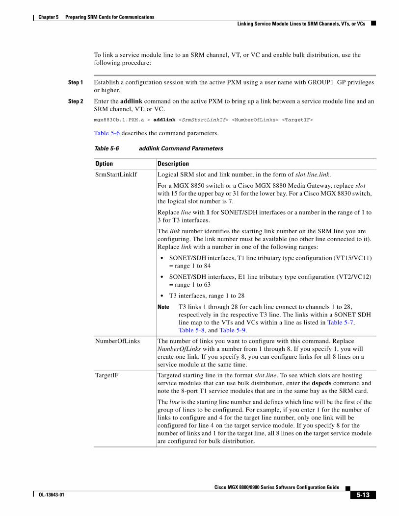
To link a service module line to an SRM channel, VT, or VC and enable bulk distribution, use the following procedure:
Step 1 Establish a configuration session with the active PXM using a user name with GROUP1_GP privileges or higher.
Step 2 Enter the addlink command on the active PXM to bring up a link between a service module line and an SRM channel, VT, or VC.
mgx8830b.1.PXM.a > addlink <SrmStartLinkIf> <NumberOfLinks> <TargetIF>
Table 5-6 describes the command parameters.
Table 5-6 addlink Command Parameters
Option Description
SrmStartLinkIf Logical SRM slot and link number, in the form of slot.line.link.
For a MGX 8850 switch or a Cisco MGX 8880 Media Gateway, replace slot with 15 for the upper bay or 31 for the lower bay. For a Cisco MGX 8830 switch, the logical slot number is 7.
Replace line with 1 for SONET/SDH interfaces or a number in the range of 1 to 3 for T3 interfaces.
The link number identifies the starting link number on the SRM line you are configuring. The link number must be available (no other line connected to it). Replace link with a number in one of the following ranges:
• SONET/SDH interfaces, T1 line tributary type configuration (VT15/VC11) = range 1 to 84
• SONET/SDH interfaces, E1 line tributary type configuration (VT2/VC12) = range 1 to 63
• T3 interfaces, range 1 to 28
Note T3 links 1 through 28 for each line connect to channels 1 to 28, respectively in the respective T3 line. The links within a SONET SDH line map to the VTs and VCs within a line as listed in Table 5-7, Table 5-8, and Table 5-9.
NumberOfLinks The number of links you want to configure with this command. Replace NumberOfLinks with a number from 1 through 8. If you specify 1, you will create one link. If you specify 8, you can configure links for all 8 lines on a service module at the same time.
TargetIF Targeted starting line in the format slot.line. To see which slots are hosting service modules that can use bulk distribution, enter the dspcds command and note the 8-port T1 service modules that are in the same bay as the SRM card.
The line is the starting line number and defines which line will be the first of the group of lines to be configured. For example, if you enter 1 for the number of links to configure and 4 for the target line number, only one link will be configured for line 4 on the target service module. If you specify 8 for the number of links and 1 for the target line, all 8 lines on the target service module are configured for bulk distribution.
5-13Cisco MGX 8800/8900 Series Software Configuration Guide
OL-13643-01
Chapter 5 Preparing SRM Cards for CommunicationsLinking Service Module Lines to SRM Channels, VTs, or VCs
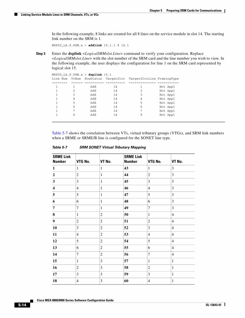
In the following example, 8 links are created for all 8 lines on the service module in slot 14. The starting link number on the SRM is 1.
M8850_LA.8.PXM.a > addlink 15.1.1 8 14.1
Step 3 Enter the dsplink <LogicalSRMslot.Line> command to verify your configuration. Replace <LogicalSRMslot.Line> with the slot number of the SRM card and the line number you wish to view. In the following example, the user displays the configuration for line 1 on the SRM card represented by logical slot 15.
M8850_LA.8.PXM.a > dsplink 15.1Line Num VtNum RowStatus TargetSlot TargetSlotLine FramingType======== ====== ========== ========== ============== =========== 1 1 Add 14 1 Not Appl 1 2 Add 14 2 Not Appl 1 3 Add 14 3 Not Appl 1 4 Add 14 4 Not Appl 1 5 Add 14 5 Not Appl 1 6 Add 14 6 Not Appl 1 7 Add 14 7 Not Appl 1 8 Add 14 8 Not Appl
Table 5-7 shows the correlation between VTs, virtual tributary groups (VTGs), and SRM link numbers when a SRME or SRME/B line is configured for the SONET line type.
Table 5-7 SRM SONET Virtual Tributary Mapping
SRME Link Number VTG No. VT No.
SRME Link Number VTG No. VT No.
1 1 1 43 1 3
2 2 1 44 2 3
3 3 1 45 3 3
4 4 1 46 4 3
5 5 1 47 5 3
6 6 1 48 6 3
7 7 1 49 7 3
8 1 2 50 1 4
9 2 2 51 2 4
10 3 2 52 3 4
11 4 2 53 4 4
12 5 2 54 5 4
13 6 2 55 6 4
14 7 2 56 7 4
15 1 3 57 1 1
16 2 3 58 2 1
17 3 3 59 3 1
18 4 3 60 4 1
5-14Cisco MGX 8800/8900 Series Software Configuration Guide
OL-13643-01
Chapter 5 Preparing SRM Cards for CommunicationsLinking Service Module Lines to SRM Channels, VTs, or VCs
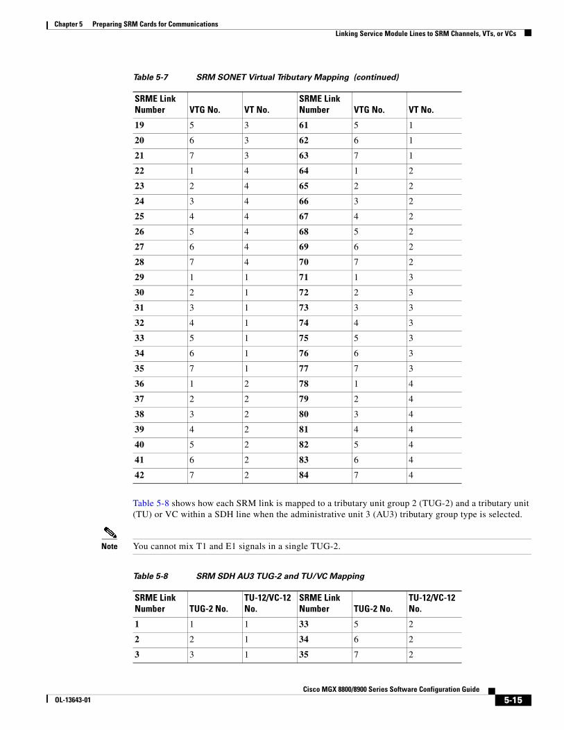
Table 5-8 shows how each SRM link is mapped to a tributary unit group 2 (TUG-2) and a tributary unit (TU) or VC within a SDH line when the administrative unit 3 (AU3) tributary group type is selected.
Note You cannot mix T1 and E1 signals in a single TUG-2.
19 5 3 61 5 1
20 6 3 62 6 1
21 7 3 63 7 1
22 1 4 64 1 2
23 2 4 65 2 2
24 3 4 66 3 2
25 4 4 67 4 2
26 5 4 68 5 2
27 6 4 69 6 2
28 7 4 70 7 2
29 1 1 71 1 3
30 2 1 72 2 3
31 3 1 73 3 3
32 4 1 74 4 3
33 5 1 75 5 3
34 6 1 76 6 3
35 7 1 77 7 3
36 1 2 78 1 4
37 2 2 79 2 4
38 3 2 80 3 4
39 4 2 81 4 4
40 5 2 82 5 4
41 6 2 83 6 4
42 7 2 84 7 4
Table 5-7 SRM SONET Virtual Tributary Mapping (continued)
SRME Link Number VTG No. VT No.
SRME Link Number VTG No. VT No.
Table 5-8 SRM SDH AU3 TUG-2 and TU/VC Mapping
SRME Link Number TUG-2 No.
TU-12/VC-12 No.
SRME Link Number TUG-2 No.
TU-12/VC-12 No.
1 1 1 33 5 2
2 2 1 34 6 2
3 3 1 35 7 2
5-15Cisco MGX 8800/8900 Series Software Configuration Guide
OL-13643-01
Chapter 5 Preparing SRM Cards for CommunicationsLinking Service Module Lines to SRM Channels, VTs, or VCs
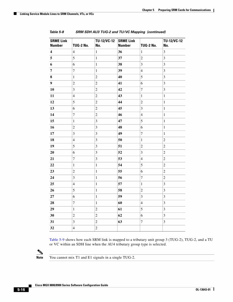
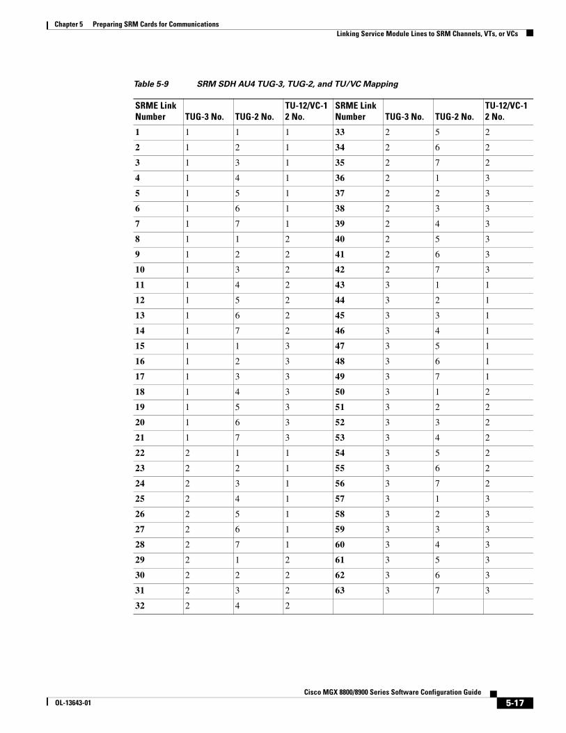
Table 5-9 shows how each SRM link is mapped to a tributary unit group 3 (TUG-2), TUG-2, and a TU or VC within an SDH line when the AU4 tributary group type is selected.
Note You cannot mix T1 and E1 signals in a single TUG-2.
4 4 1 36 1 3
5 5 1 37 2 3
6 6 1 38 3 3
7 7 1 39 4 3
8 1 2 40 5 3
9 2 2 41 6 3
10 3 2 42 7 3
11 4 2 43 1 1
12 5 2 44 2 1
13 6 2 45 3 1
14 7 2 46 4 1
15 1 3 47 5 1
16 2 3 48 6 1
17 3 3 49 7 1
18 4 3 50 1 2
19 5 3 51 2 2
20 6 3 52 3 2
21 7 3 53 4 2
22 1 1 54 5 2
23 2 1 55 6 2
24 3 1 56 7 2
25 4 1 57 1 3
26 5 1 58 2 3
27 6 1 59 3 3
28 7 1 60 4 3
29 1 2 61 5 3
30 2 2 62 6 3
31 3 2 63 7 3
32 4 2
Table 5-8 SRM SDH AU3 TUG-2 and TU/VC Mapping (continued)
SRME Link Number TUG-2 No.
TU-12/VC-12 No.
SRME Link Number TUG-2 No.
TU-12/VC-12 No.
5-16Cisco MGX 8800/8900 Series Software Configuration Guide
OL-13643-01
Chapter 5 Preparing SRM Cards for CommunicationsLinking Service Module Lines to SRM Channels, VTs, or VCs
Table 5-9 SRM SDH AU4 TUG-3, TUG-2, and TU/VC Mapping
SRME Link Number TUG-3 No. TUG-2 No.
TU-12/VC-12 No.
SRME Link Number TUG-3 No. TUG-2 No.
TU-12/VC-12 No.
1 1 1 1 33 2 5 2
2 1 2 1 34 2 6 2
3 1 3 1 35 2 7 2
4 1 4 1 36 2 1 3
5 1 5 1 37 2 2 3
6 1 6 1 38 2 3 3
7 1 7 1 39 2 4 3
8 1 1 2 40 2 5 3
9 1 2 2 41 2 6 3
10 1 3 2 42 2 7 3
11 1 4 2 43 3 1 1
12 1 5 2 44 3 2 1
13 1 6 2 45 3 3 1
14 1 7 2 46 3 4 1
15 1 1 3 47 3 5 1
16 1 2 3 48 3 6 1
17 1 3 3 49 3 7 1
18 1 4 3 50 3 1 2
19 1 5 3 51 3 2 2
20 1 6 3 52 3 3 2
21 1 7 3 53 3 4 2
22 2 1 1 54 3 5 2
23 2 2 1 55 3 6 2
24 2 3 1 56 3 7 2
25 2 4 1 57 3 1 3
26 2 5 1 58 3 2 3
27 2 6 1 59 3 3 3
28 2 7 1 60 3 4 3
29 2 1 2 61 3 5 3
30 2 2 2 62 3 6 3
31 2 3 2 63 3 7 3
32 2 4 2
5-17Cisco MGX 8800/8900 Series Software Configuration Guide
OL-13643-01
Chapter 5 Preparing SRM Cards for CommunicationsWhere To Go Next
Where To Go NextWhen your line configuration is complete and links have been established (if using bulk distribution), you are ready to start provisioning connections. To provision connections on a particular service module, you need to refer to the appropriate software configuration guide (see Table 1-1).
5-18Cisco MGX 8800/8900 Series Software Configuration Guide
OL-13643-01