prescott operations manual-2006v2 - tru drill energy … · the prescott drilling motors operations...
TRANSCRIPT

OPERATIONS MANUAL

INTRODUCTION
INTRODUCTION
The Prescott Drilling Motors Operations Manual covers basic procedures and principals in the operation of Prescott positive displacement mud motors.This manual includes basic operating information, specifications and tool parameters and also provides general information for the user to operate ourequipment safely and effectively. As always, specific applications may dictate changes in procedures, therefore this manual is to be used as aguideline only. If there are any questions, please contact your nearest Prescott Drilling Motors representative.
This manual includes basic engineering data for use at the rig. In addition, specifications for each motor power section are available to help the useridentify the proper power section for optimum drilling performance.
Printed in CanadaAugust 2006

NQL Energy Services Prescott Mud MotorNQL Energy Services Product Line Overview 1 Prescott Mud Motor Introduction 2Proceedures 3Prescott Mud Motors 4
Torque Connections 5Build Rates 6Adjustable Bent Housing - ABH 7 Mud Motors 10
CONTENTS
Table of ContentsFISHING DIMENSIONSMud Motor Fishing Dimensions 21
CONVERSION TABLES AND OFFICE LOCATIONSMud Weights 23Conversions 24Locations 27
NQL
PRODUCT
OVERVIEW2
NQL Energy Services Complete Product Line
NQL Energy Services newest addition is Prescott Drilling Motors who manufacture a high quality mud lubricated motor. The mud lubricated motor is a distinct andseparate product from the oil lubricated and sealed motor designs also offered by NQL Energy Services
NQL has a complete line up of Drilling Motors including the BlackMax line of quality drilling tools includes drilling motors, shock tools, two types of mechanical drilling jars, ahydraulic mechanical drilling jar, and a hydraulic drilling jar. In sizes ranging from 1 11/16" OD to 11 1/4" OD, NQL has a drilling tool for any application.
BlackMax Mud Motors range in size from 1 11/16"OD to 11 ¼" OD. With over 80 different configurations, BlackMax Mud Motors provide our customers with the versatilityto tailor the motor to a specific bit and drilling application. With our combinations of power sections, rugged drive shafts, and sealed thrust bearing assemblies BlackMaxcan build the exact tool to perform the job to the highest quality expected of their customers. BlackMax Mud Motors have drilled hundreds of thousands of feet of hole by marrying the power section you need with the bit required in the application.
Black Max Shock Tools range in size from 2 7/8" OD to 11" OD. Designed to cushion heavy axial loading and reduce bit vibrations, BlackMax Shock Tools will extenddrillstring component and bit life to help reduce drilling costs. BlackMax Shock Tools are sprung for compression and tension, are pressure balanced from hydrostaticpressures, and come in string or bottom hole configurations.
BlackMax Rayson Mechanical Jars and Best Hitter Mechanical Jars are designed to create powerful mechanical jarring action to free drill strings that have becomestuck. They are oil lubricated and are designed to work in the harshest of drilling environments.
BlackMax Hydraulic Mechanical Jars have a mechanical latch feature that keeps the jar in the neutral position and prevents unexpected jarring while tripping in or out ofthe hole. The jars have a hydraulic valve that creates a time delay when the jar is in operation and the latch is disengaged.
BlackMax "Rig Rattler" Jars are a hydraulic tool that jars up and has a mechanical "bump" down. The Rig Rattler has been a proven solution to stuck pipe in manyapplications, and provides a maximum jar action when needed most.
In 2005 NQL Energy Services also introduced the Stabeco product line to compliment its' existing drilling products - Please refer to the Stabeco Motor Manual (available Fall 2006) or Brochure for more information
1
MUD
MOTOR
DESIGN
PRESCOTT MUD MOTOR DESIGN
(A) Bearing AssemblyThe Prescott Bearing assemblies are a reliable and proven flow-thru design. The bearing pack is very rugged and will stand up to the harshest drillingconditions. The bearing race stack uses the toughest tool steel material specially heat treated to a Prescott proprietary specification which maximizedtoughness while increasing wear resistance resulting in a longer bearing's life. Upper and lower radial bearing support bushing are case hardened andare very cost effective. All these features result in a longer lasting and very reliable bearing pack.
(B) Jaw Clutch TransmissionPrescott incorporates the proven and long lasting jaw clutch transmission to transmit torque from the rotor to the output shaft and eliminates sideloading caused by rotor eccentricity. The patented (US 7,004,843) innovative double-pinned design results in longer component life, higher tensilestrength and can be used up to 4 degrees.
(C) Adjustable bent Housing/Fixed HousingThe Prescott ABH is a patented (US 6,554,083) one of a kind tool, which allows for easy adjustment of the bend angle. Simple yet effective design isvery strong and a single setscrew locks the desired angle in place until the unit is torqued. The ABH is available up to 3 degree in ¼ degreeincrements. Always follow the specifications for proper torquing of the assembly.
(D) Power SectionsPrescott power sections are made up of a lobed rotor that fits inside an elastomer lined housing (stator). The rotor has one less lobe than the statorcreating a continuously sealing chamber. Drilling fluid or gas is forced through the motor, thereby turning the rotor and generating torque.
Where drilling requirements call for circulation rates exceeding maximum recommended rates, rotors are jetted to allow excessive fluid to flow down aparallel path, thereby reducing damage to the elastomer in the stator.
2
PROCEDURES
3
PROCEDURES
Introduction
This section describes basic operating procedures, which are used in the field and will facilitate proper operation of Prescott motors.
Bit Selection
An important aspect of any planned down hole motor run, is properly matching the bit and hydraulics to the motor in order to achieve the desired results.Attention must be given to TFA (total flow area) to see that proper parameters are maintained with regard to pressure drop across bit, annular velocityneeded for hole cleaning, maximum standpipe pressure, and adequate hole cleaning at the bit/formation interface. Keep in mind that stalls pressure ofa motor may approach pump relief valve limits in some cases. In larger hole sizes, a bored rotor may be necessary to accommodate fluid requirementsmentioned above. Generally, all motor sizes have adequate torque to run any cone type bit. Aggressive PDC bits may cause stalling in rough and brokenformations. If the purpose of the run is to build angle, or otherwise achieve significant deviation, gauge length on the bit is very important. Gaugeprotection is necessary if the motor is bent, since continual side loading occurs at the bit.

MUD
MOTORS
PRESCOTT MUD MOTORS
4
For More Information Visit us on the Website at
www.nql.com
TORQUE
CONNECTIONS
5
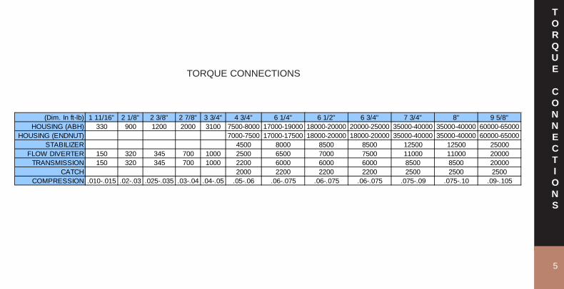
(Dim. In ft-lb) 1 11/16" 2 1/8" 2 3/8" 2 7/8" 3 3/4" 4 3/4" 6 1/4" 6 1/2" 6 3/4" 7 3/4" 8" 9 5/8"HOUSING (ABH) 330 900 1200 2000 3100 7500-8000 17000-19000 18000-20000 20000-25000 35000-40000 35000-40000 60000-65000
HOUSING (ENDNUT) 7000-7500 17000-17500 18000-20000 18000-20000 35000-40000 35000-40000 60000-65000STABILIZER 4500 8000 8500 8500 12500 12500 25000
FLOW DIVERTER 150 320 345 700 1000 2500 6500 7000 7500 11000 11000 20000TRANSMISSION 150 320 345 700 1000 2200 6000 6000 6000 8500 8500 20000
CATCH 2000 2200 2200 2200 2500 2500 2500COMPRESSION .010-.015 .02-.03 .025-.035 .03-.04 .04-.05 .05-.06 .06-.075 .06-.075 .06-.075 .075-.09 .075-.10 .09-.105
TORQUE CONNECTIONS
6
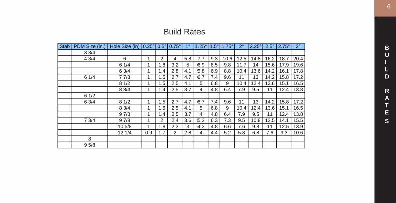
Stab PDM Size (in.) Hole Size (in) 0.25° 0.5° 0.75° 1° 1.25° 1.5° 1.75° 2° 2.25° 2.5° 2.75° 3°3 3/44 3/4 6 1 2 4 5.8 7.7 9.3 10.6 12.5 14.8 16.2 18.7 20.4
6 1/4 1 1.8 3.2 5 6.9 8.5 9.8 11.7 14 15.6 17.9 19.66 3/4 1 1.4 2.8 4.1 5.8 6.9 8.8 10.4 13.6 14.2 16.1 17.8
6 1/4 7 7/8 1 1.5 2.7 4.7 6.7 7.4 9.6 11 13 14.2 15.8 17.28 1/2 1 1.5 2.5 4.1 5 6.8 9 10.4 12.4 13.6 15.1 16.58 3/4 1 1.4 2.5 3.7 4 4.8 6.4 7.9 9.5 11 12.4 13.8
6 1/26 3/4 8 1/2 1 1.5 2.7 4.7 6.7 7.4 9.6 11 13 14.2 15.8 17.2
8 3/4 1 1.5 2.5 4.1 5 6.8 9 10.4 12.4 13.6 15.1 16.59 7/8 1 1.4 2.5 3.7 4 4.8 6.4 7.9 9.5 11 12.4 13.8
7 3/4 9 7/8 1 2 2.4 3.6 5.2 6.3 7.3 9.5 10.8 12.5 14.1 15.510 5/8 1 1.8 2.3 3 4.3 4.8 6.6 7.6 9.8 11 12.5 13.912 1/4 0.9 1.7 2 2.8 4 4.4 5.2 5.8 6.8 7.6 9.3 10.6
89 5/8
Build Rates
BUILD
RATES

1 2 3 4 5 6 7
Item Number Part Description Quantity Required4.3/4" 6.3/4" 8." 9.5/8"
1 ABH Upper 1 475-401 675-401 800-401 962-4012 Upper O-Ring 13 Outer Spline Ring 1 475-403 675-403 800-403 962.4034 ABH Set Screw 15 Inner Spline Ring 1 475-405 675-405 800-405 962-4056 Inner O-Ring 17 ABH Lower 1 475-407 675-407 800-407 962-407
Motor Size /Part NumberAdjustable Bent Housing Parts List/Parts Numbers
ADJUSTABLE
BENT
HOUSING
7
APPLICATIONS
8
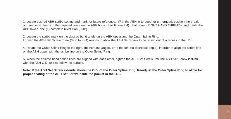
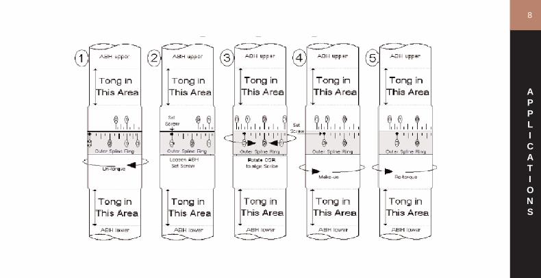
1. Locate desired ABH scribe setting and mark for future reference. With the ABH in torqued, or un-torqued, position the breakout unit or rig tongs in the required place on the ABH body. (See Figure 7.4). Untorque, (RIGHT HAND THREAD), and rotate theABH lower one (1) complete revolution (360°).
2. Locate the scribe mark on the desired bend angle on the ABH upper and the Outer Spline Ring.Loosen the ABH Set Screw three (3) to four (4) rounds to allow the ABH Set Screw to be raised out of a recess in the I.D...
4. Rotate the Outer Spline Ring to the right, (to increase angle), or to the left, (to decrease angle), in order to align the scribe lineon the ABH upper with the scribe line on the Outer Spline Ring.
5. When the desired bend scribe lines are aligned with each other, tighten the ABH Set Screw until the ABH Set Screw is flushwith the ABH O.D. or sits below the surface.
Note: If the ABH Set Screw extends above the O.D. of the Outer Spline Ring. Re-adjust the Outer Spline Ring to allow forproper seating of the ABH Set Screw inside the pocket in the I.D...
9
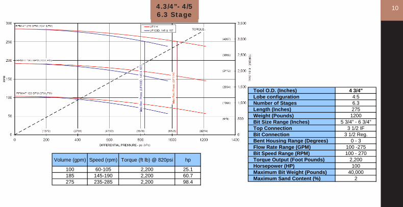
Tool O.D. (Inches) 4 3/4"Lobe configuration 4:5Number of Stages 6.3Length (Inches) 275Weight (Pounds) 1200Bit Size Range (Inches) 5 3/4" - 6 3/4"Top Connection 3 1/2 IFBit Connection 3 1/2 Reg.Bent Housing Range (Degrees) 0 - 3Flow Rate Range (GPM) 100 -275Bit Speed Range (RPM) 100 - 270Torque Output (Foot Pounds) 2,200Horsepower (HP) 100Maximum Bit Weight (Pounds) 40,000Maximum Sand Content (%) 2
4.3/4”- 4/56.3 Stage
Volume (gpm) Speed (rpm) Torque (ft lb) @ 820psi hp
100 60-105 2,200 25.1185 145-190 2,200 60.7275 235-285 2,200 98.4
10
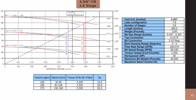
4.3/4”-7/83.8 Stage
Tool O.D. (Inches) 4 3/4"Lobe configuration 7:8Number of Stages 3.8Length (Inches) 265.5Weight (Pounds) 1100Bit Size Range (Inches) 5 3/4" - 6 3/4"Top Connection 3 1/2 IFBit Connection 3 1/2 Reg.Bent Housing Range (Degrees) 0 - 3Flow Rate Range (GPM) 100-275Bit Speed Range (RPM) 59-160Torque Output (Foot Pounds) 2,200Horsepower (HP) 55Maximum Bit Weight (Pounds) 40,000Maximum Sand Content (%) 2
Volume (gpm) Speed (rpm) Torque (ft lb) @ 475psi hp
100 32-58 2,200 13.4185 81-108 2,200 33.9275 132-160 2,200 55.3
11

124.3/4” ERT - 4/53.6 stage
Tool O.D. (Inches) 4 3/4" ERTLobe configuration 4:5Number of Stages 3.6Length (Inches) 205Weight (Pounds) 900Bit Size Range (Inches) 5 3/4" - 6 3/4"Top Connection 3 1/2 IFBit Connection 3 1/2 Reg.Bent Housing Range (Degrees) 0 - 3Flow Rate Range (GPM) 150-300Bit Speed Range (RPM) 150-300Torque Output (Foot Pounds) 3,150Horsepower (HP) 72Maximum Bit Weight (Pounds) 40,000Maximum Sand Content (%) 2
Volume (gpm) Speed (rpm) Torque (ft lb) @ 1300psi hp150 75-150 3,150 18.0225 135-225 3,150 43.2300 200-300 3,150 72.0
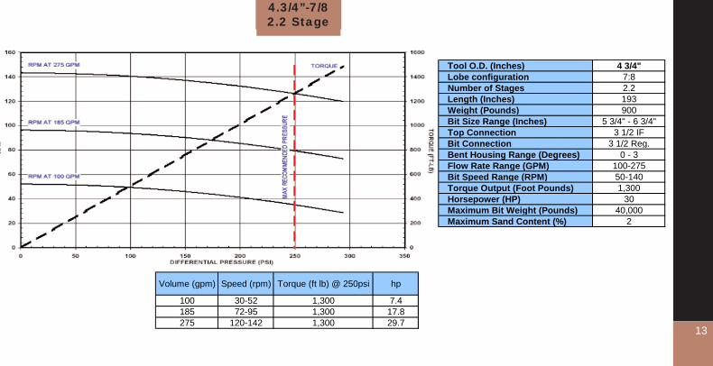
4.3/4”-7/82.2 Stage
Tool O.D. (Inches) 4 3/4"Lobe configuration 7:8Number of Stages 2.2Length (Inches) 193Weight (Pounds) 900Bit Size Range (Inches) 5 3/4" - 6 3/4"Top Connection 3 1/2 IFBit Connection 3 1/2 Reg.Bent Housing Range (Degrees) 0 - 3Flow Rate Range (GPM) 100-275Bit Speed Range (RPM) 50-140Torque Output (Foot Pounds) 1,300Horsepower (HP) 30Maximum Bit Weight (Pounds) 40,000Maximum Sand Content (%) 2
Volume (gpm) Speed (rpm) Torque (ft lb) @ 250psi hp
100 30-52 1,300 7.4185 72-95 1,300 17.8275 120-142 1,300 29.7
13
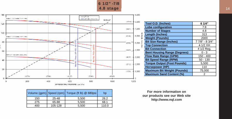
Volume (gpm) Speed (rpm) Torque (ft lb) @ 680psi hp
150 25-48 5,500 26.2275 65-88 5,500 68.1400 105-128 5,500 110.0
Tool O.D. (Inches) 6 1/4"Lobe configuration 7:8Number of Stages 4.8Length (Inches) 313Weight (Pounds) 2000Bit Size Range (Inches) 7 7/8" - 8 3/4"Top Connection 4 1/2 XHBit Connection 4 1/2 Reg.Bent Housing Range (Degrees) 0 - 3Flow Rate Range (GPM) 150 - 400Bit Speed Range (RPM) 50 - 130Torque Output (Foot Pounds) 5,500Horsepower (HP) 110Maximum Bit Weight (Pounds) 75,000Maximum Sand Content (%) 2
6 1/2” -7/84.8 stage
For more information onour products see our Web site
http://www.nql.com
14

6.3/4” - 6/73.1 Stage
Tool O.D. (Inches) 6 3/4" ERTLobe configuration 6:7Number of Stages 3.1Length (Inches) 241Weight (Pounds) 2700Bit Size Range (Inches) 8 1/2" - 9 7/8"Top Connection 4 1/2 IFBit Connection 4 1/2 Reg.Bent Housing Range (Degrees) 0 - 3Flow Rate Range (GPM) 300 - 650Bit Speed Range (RPM) 110 - 240Torque Output (Foot Pounds) 8,630Horsepower (HP) 197Maximum Bit Weight (Pounds) 80,000Maximum Sand Content (%) 2
Volume (gpm) Speed (rpm) Torque (ft lb) @ 1250psi hp300 50-110 8,630 49.3475 100-175 8,630 118.3650 150-240 8,630 197.2
15

166 3/4” -7/8
3 stage
Volume (gpm) Speed (rpm) Torque (ft lb) @ 360psi hp
300 52-85 3,400 33.7450 95-125 3,400 61.5600 138-168 3,400 89.3
Tool O.D. (Inches) 6 3/4"Lobe configuration 7:8Number of Stages 3Length (Inches) 227Weight (Pounds) 2000Bit Size Range (Inches) 8 1/2" - 9 7/8"Top Connection 4 1/2 IFBit Connection 4 1/2 Reg.Bent Housing Range (Degrees) 0 - 3Flow Rate Range (GPM) 300 - 600Bit Speed Range (RPM) 80 - 170Torque Output (Foot Pounds) 3,400Horsepower (HP) 90Maximum Bit Weight (Pounds) 80,000Maximum Sand Content (%) 2
17
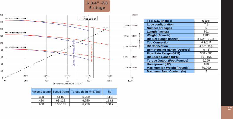
Tool O.D. (Inches) 6 3/4"Lobe configuration 7:8Number of Stages 5Length (Inches) 301Weight (Pounds) 2200Bit Size Range (Inches) 8 1/2" - 9 7/8"Top Connection 4 1/2 IFBit Connection 4 1/2 Reg.Bent Housing Range (Degrees) 0 - 3Flow Rate Range (GPM) 300 - 600Bit Speed Range (RPM) 80 - 165Torque Output (Foot Pounds) 6,250Horsepower (HP) 160Maximum Bit Weight (Pounds) 80,000Maximum Sand Content (%) 2
Volume (gpm) Speed (rpm) Torque (ft lb) @ 675psi hp
300 54-82 6,250 64.3450 95-125 6,250 113.1600 135-165 6,250 160.7
6 3/4” -7/85 stage

Volume (gpm) Speed (rpm) Torque (ft lb) @ 330psi hp
300 22-48 5,500 23.0600 70-95 5,500 73.3900 118-145 5,500 123.6
Tool O.D. (Inches) 7 3/4"Lobe configuration 7:8Number of Stages 3Length (Inches) 280Weight (Pounds) 2800Bit Size Range (Inches) 9 7/8" - 12 1/4"Top Connection 6 5/8 Reg.Bit Connection 6 5/8 Reg.Bent Housing Range (Degrees) 0 - 3Flow Rate Range (GPM) 300 - 900Bit Speed Range (RPM) 50 - 150Torque Output (Foot Pounds) 5,500Horsepower (HP) 125Maximum Bit Weight (Pounds) 100,000Maximum Sand Content (%) 2
7 3/4” -7/83 stage
18
19
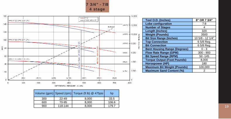
Volume (gpm) Speed (rpm) Torque (ft lb) @ 475psi hp
300 22-49 8,000 33.5600 70-95 8,000 106.6900 118-144 8,000 179.7
Tool O.D. (Inches) 8" OR 7 3/4"Lobe configuration 7:8Number of Stages 4Length (Inches) 320Weight (Pounds) 3500Bit Size Range (Inches) 10 5/8 - 12 1/4"Top Connection 6 5/8 Reg.Bit Connection 6 5/8 Reg.Bent Housing Range (Degrees) 0 - 3Flow Rate Range (GPM) 300 - 900Bit Speed Range (RPM) 50 -145Torque Output (Foot Pounds) 8,000Horsepower (HP) 180Maximum Bit Weight (Pounds) 100,000Maximum Sand Content (%) 2
7 3/4” - 7/84 stage
MUD
MOTORS
20
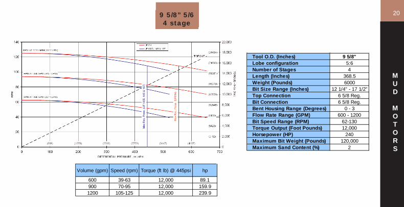
Tool O.D. (Inches) 9 5/8"Lobe configuration 5:6Number of Stages 4Length (Inches) 368.5Weight (Pounds) 6000Bit Size Range (Inches) 12 1/4" - 17 1/2"Top Connection 6 5/8 Reg.Bit Connection 6 5/8 Reg.Bent Housing Range (Degrees) 0 - 3Flow Rate Range (GPM) 600 - 1200Bit Speed Range (RPM) 62-130Torque Output (Foot Pounds) 12,000Horsepower (HP) 240Maximum Bit Weight (Pounds) 120,000Maximum Sand Content (%) 2
Volume (gpm) Speed (rpm) Torque (ft lb) @ 445psi hp
600 39-63 12,000 89.1900 70-95 12,000 159.91200 105-125 12,000 239.9
9 5/8” 5/64 stage
21
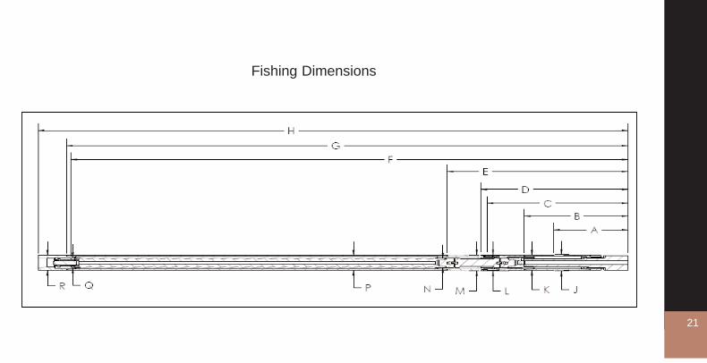
Fishing Dimensions
21
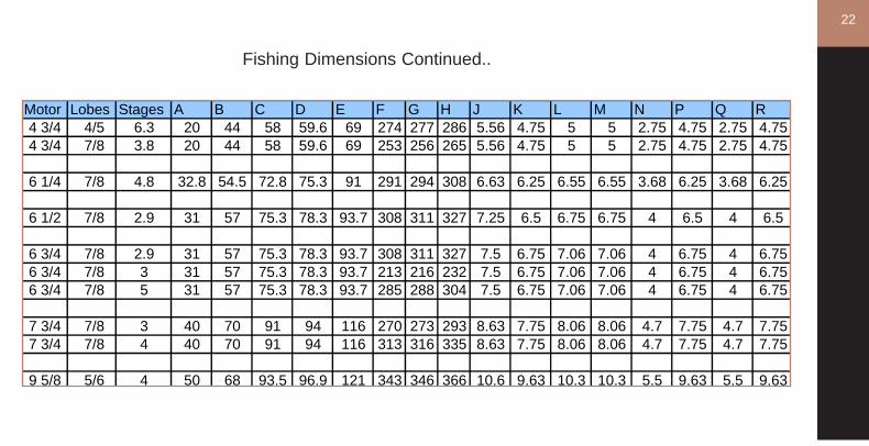
Motor Lobes Stages A B C D E F G H J K L M N P Q R4 3/4 4/5 6.3 20 44 58 59.6 69 274 277 286 5.56 4.75 5 5 2.75 4.75 2.75 4.754 3/4 7/8 3.8 20 44 58 59.6 69 253 256 265 5.56 4.75 5 5 2.75 4.75 2.75 4.75
6 1/4 7/8 4.8 32.8 54.5 72.8 75.3 91 291 294 308 6.63 6.25 6.55 6.55 3.68 6.25 3.68 6.25
6 1/2 7/8 2.9 31 57 75.3 78.3 93.7 308 311 327 7.25 6.5 6.75 6.75 4 6.5 4 6.5
6 3/4 7/8 2.9 31 57 75.3 78.3 93.7 308 311 327 7.5 6.75 7.06 7.06 4 6.75 4 6.756 3/4 7/8 3 31 57 75.3 78.3 93.7 213 216 232 7.5 6.75 7.06 7.06 4 6.75 4 6.756 3/4 7/8 5 31 57 75.3 78.3 93.7 285 288 304 7.5 6.75 7.06 7.06 4 6.75 4 6.75
7 3/4 7/8 3 40 70 91 94 116 270 273 293 8.63 7.75 8.06 8.06 4.7 7.75 4.7 7.757 3/4 7/8 4 40 70 91 94 116 313 316 335 8.63 7.75 8.06 8.06 4.7 7.75 4.7 7.75
9 5/8 5/6 4 50 68 93.5 96.9 121 343 346 366 10.6 9.63 10.3 10.3 5.5 9.63 5.5 9.63
Fishing Dimensions Continued..
22
23
MUD
WEIGHT
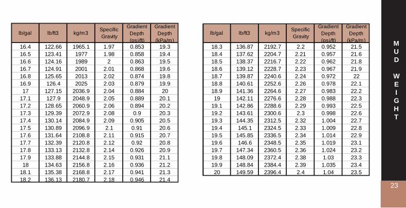
lb/gal lb/ft3 kg/m3Specific Gravity
Gradient Depth (psi/ft)
Gradient Depth
(kPa/m)18.3 136.87 2192.7 2.2 0.952 21.518.4 137.62 2204.7 2.21 0.957 21.618.5 138.37 2216.7 2.22 0.962 21.818.6 139.12 2228.7 2.23 0.967 21.918.7 139.87 2240.6 2.24 0.972 2218.8 140.61 2252.6 2.26 0.978 22.118.9 141.36 2264.6 2.27 0.983 22.219 142.11 2276.6 2.28 0.988 22.3
19.1 142.86 2288.6 2.29 0.993 22.519.2 143.61 2300.6 2.3 0.998 22.619.3 144.35 2312.5 2.32 1.004 22.719.4 145.1 2324.5 2.33 1.009 22.819.5 145.85 2336.5 2.34 1.014 22.919.6 146.6 2348.5 2.35 1.019 23.119.7 147.34 2360.5 2.36 1.024 23.219.8 148.09 2372.4 2.38 1.03 23.319.9 148.84 2384.4 2.39 1.035 23.420 149.59 2396.4 2.4 1.04 23.5
lb/gal lb/ft3 kg/m3Specific Gravity
Gradient Depth (psi/ft)
Gradient Depth
(kPa/m)16.4 122.66 1965.1 1.97 0.853 19.316.5 123.41 1977 1.98 0.858 19.416.6 124.16 1989 2 0.863 19.516.7 124.91 2001 2.01 0.868 19.616.8 125.65 2013 2.02 0.874 19.816.9 126.4 2025 2.03 0.879 19.917 127.15 2036.9 2.04 0.884 20
17.1 127.9 2048.9 2.05 0.889 20.117.2 128.65 2060.9 2.06 0.894 20.217.3 129.39 2072.9 2.08 0.9 20.317.4 130.14 2084.9 2.09 0.905 20.517.5 130.89 2096.9 2.1 0.91 20.617.6 131.64 2108.8 2.11 0.915 20.717.7 132.39 2120.8 2.12 0.92 20.817.8 133.13 2132.8 2.14 0.926 20.917.9 133.88 2144.8 2.15 0.931 21.118 134.63 2156.8 2.16 0.936 21.2
18.1 135.38 2168.8 2.17 0.941 21.318.2 136.13 2180.7 2.18 0.946 21.4
CONVERSIONS
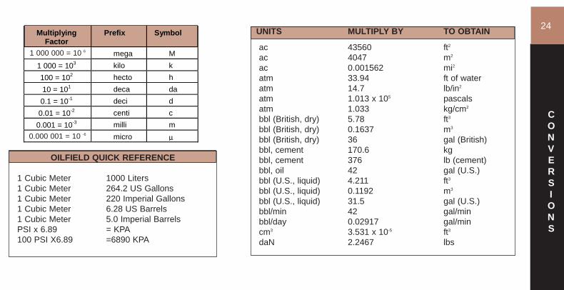
UNITS MULTIPLY BY TO OBTAIN
ac 43560 ft2
ac 4047 m2
ac 0.001562 mi2atm 33.94 ft of wateratm 14.7 lb/in2
atm 1.013 x 10⁵ pascalsatm 1.033 kg/cm2
bbl (British, dry) 5.78 ft3
bbl (British, dry) 0.1637 m3
bbl (British, dry) 36 gal (British)bbl, cement 170.6 kgbbl, cement 376 lb (cement)bbl, oil 42 gal (U.S.)bbl (U.S., liquid) 4.211 ft3
bbl (U.S., liquid) 0.1192 m3
bbl (U.S., liquid) 31.5 gal (U.S.)bbl/min 42 gal/minbbl/day 0.02917 gal/mincm3 3.531 x 10⁻⁵ ft3
daN 2.2467 lbs
Multiplying Factor
Prefix Symbol
1 000 000 = 6
mega M 1 000 = 103 kilo k 100 = 102 hecto h 10 = 101 deca da 0.1 = 10-1 deci d 0.01 = 10-2 centi c
0.001 = 10-3 milli m 0.000 001 =
6micro μ
OILFIELD QUICK REFERENCE
1 Cubic Meter 1000 Liters1 Cubic Meter 264.2 US Gallons1 Cubic Meter 220 Imperial Gallons1 Cubic Meter 6.28 US Barrels1 Cubic Meter 5.0 Imperial BarrelsPSI x 6.89 = KPA100 PSI X6.89 =6890 KPA
1 000 000 = 10 6
0.000 001 = 10 -6
24
CONVERSIONS
25
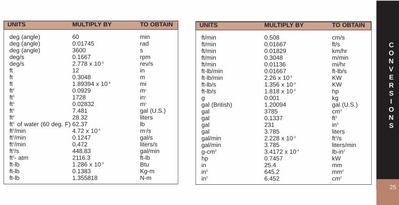
UNITS MULTIPLY BY TO OBTAIN
ft/min 0.508 cm/sft/min 0.01667 ft/sft/min 0.01829 km/hrft/min 0.3048 m/minft/min 0.01136 mi/hrft-lb/min 0.01667 ft-lb/sft-lb/min 2.26 x 10⁻⁵ KWft-lb/s 1.356 x 10⁻³ KWft-lb/s 1.818 x 10⁻³ hpg 0.001 kg gal (British) 1.20094 gal (U.S.)gal 3785 cm3
gal 0.1337 ft3
gal 231 in3
gal 3.785 litersgal/min 2.228 x 10⁻³ ft3/sgal/min 3.785 liters/ming-cm2 3.4172 x 10⁻⁴ lb-in2
hp 0.7457 kWin 25.4 mmin2 645.2 mm2
in2 6.452 cm2
UNITS MULTIPLY BY TO OBTAIN
deg (angle) 60 mindeg (angle) 0.01745 raddeg (angle) 3600 sdeg/s 0.1667 rpmdeg/s 2.778 x 10⁻³ rev/sft 12 inft 0.3048 mft 1.89394 x 10⁻⁴ mift2 0.0929 m2
ft3 1728 in3
ft3 0.02832 m3
ft3 7.481 gal (U.S.)ft3 28.32 litersft3 of water (60 deg. F) 62.37 lbft3/min 4.72 x 10⁻⁴ m3/sft3/min 0.1247 gal/sft3/min 0.472 liters/sft3/s 448.83 gal/minft3- atm 2116.3 ft-lb ft-lb 1.286 x 10⁻³ Btuft-lb 0.1383 Kg-mft-lb 1.355818 N-m

CONVERSIONS
26UNITS MULTIPLY BY TO OBTAIN
lb/in2 6.894757 kPaliter 0.03531 ft3
liter 0.001 m3
liter 0.2642 gal liter 0.001 m3
liter 0.2642 gal m 3.2808 ftm2 10.764 ft2
m3 264.2 gal m3/s 15850 gal/min m3/s 60000 liters/min mi 2 2.788 x 107 ft2
mi 2 2.59 km2
rad 57.3 degrad/s 0.1592 rev/srad/s 9.549 rpmtemp. (°C) 1.8 (°C)+32 temp. °Ftemp. (°F) (°F - 32) 5/9 temp. °Ctons (metric) 1000 kgwatts 0.7376 ft-lb/swatts 1.341 x 10⁻³ hpyds 3 ftyds 0.9144 m
UNITS MULTIPLY BY TO OBTAIN
in2 6.944 x 10⁻³ ft2
in3 1.639 x 10⁻⁵
m3
in3 5.787 x 10⁻⁴
ft3
in3 4.329 x 10⁻³ galin3 0.01639 literskg 2.2046 lbkg-m 7.233 ft-lbkg/m3 0.06243 lb/ft3
kg/m 0.672 lb/ftkW 44250 ft-lb/minkW-hr 2.655 x 106 ft-lblb 4.45 x 10⁵ dyneslb 4.448 newtonslb 4.535 x 10⁻⁴ tons (metric)lb/ft3 16.02 kg/m3
lb/ft3 5.787 x 10⁻⁴ lb/in3
lb/ft2 4.882 kg/m2
lb/ft2 6.945 x 10⁻³ lb/in2
lb/gal 7.48 lb/ft3
lb/gal .12 specific grav.lb/gal .1198 g/cm3

OFFICE
LOCATIONS
CanadaNisku (Edmonton) AlbertaPh: 780-955-8828
Calgary, AlbertaPh: 403-266-3700
Estevan, SaskatchewanPh: 306-634-8828
USABakersfield, CaliforniaPh: 661-327-0226
Casper, WyomingPh: 307-237-9163
Baker, MTPh:(406) 853-2738
Interlochen, MichiganPh: 231-357-3377
Lafayette, LouisianaPh: 337-856-1060
Odessa, TexasPh: 432-580-5346
Oklahoma City, OklahomaPh: 405-688-5000
Denver, ColoradoPh: 303-825-0399
Stafford, TexasPh: 281-568-1336
Vernal, UtahPh: 435-828-8130
Grand Junction, COPh: 970 640-1095
Willis, TexasPh: (936) 344-7700
Youngsville, LAPh: 337 856-5300
InternationalNeuquen 8300, ArgentinaPh: 54-299-448-2808
Santa Cruz, BoliviaPh: 5913-352-4107
Akersloot, The NetherlandsPh: 31-72-53-53-53-5
Dubai, United Arab EmiratesPh: 9714-347-7719
Ciudad Ojeda, Estado Zulia, VenezuelaPh: 58-265-631-0511
Anaco, Estado Anzoategul, VenezuelaPh: 58-282-425-5478
Barinas, Estado Barinas, VenezuelaPh: 58-273-533-0808
Head Office1507 - 4th Street
Nisku, Alberta. Canada T9E 7M9 PH: 780-955-8828
For complete address and contact information see NQL’s website at www.nql.com

HEAD OFFICENQL Energy Services
1507- 4 StreetNisku, Alberta, Canada T9E 7M9
Phone: 780-955-8828 Fax 780-955-3309website: www.nql.com
© August 2006NQL Energy Services