present status and future challenges of ccs in japan · present status and future challenges of ccs...
TRANSCRIPT
Present Status andFuture Challenges of CCS in Japan
Takuro OkajimaChief Administrator,
Global Environmental Partnership Office, Ministry of Economy, Trade and Industry, Japan
Nov. 17, 2016
1
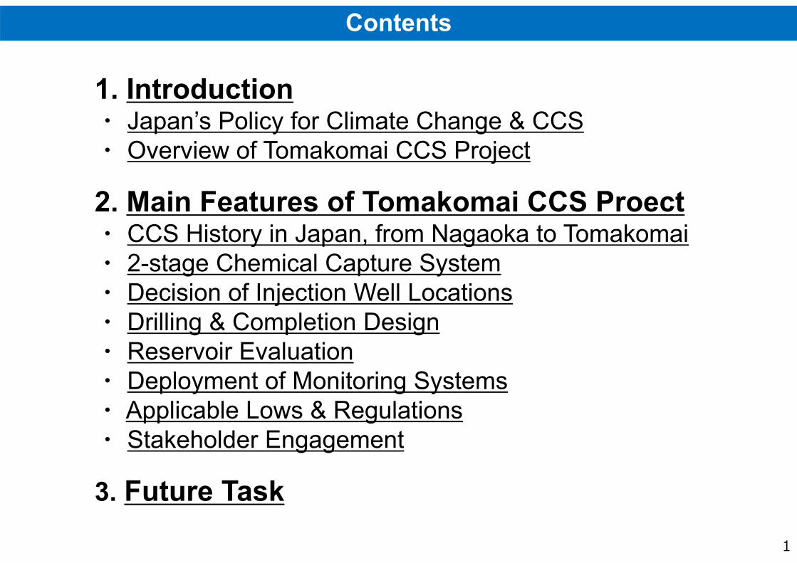
1. Introduction・ Japan’s Policy for Climate Change & CCS・ Overview of Tomakomai CCS Project
2. Main Features of Tomakomai CCS Proect・ CCS History in Japan, from Nagaoka to Tomakomai・ 2-stage Chemical Capture System・ Decision of Injection Well Locations・ Drilling & Completion Design・ Reservoir Evaluation・ Deployment of Monitoring Systems・ Applicable Lows & Regulations・ Stakeholder Engagement
3. Future Task
Contents
2
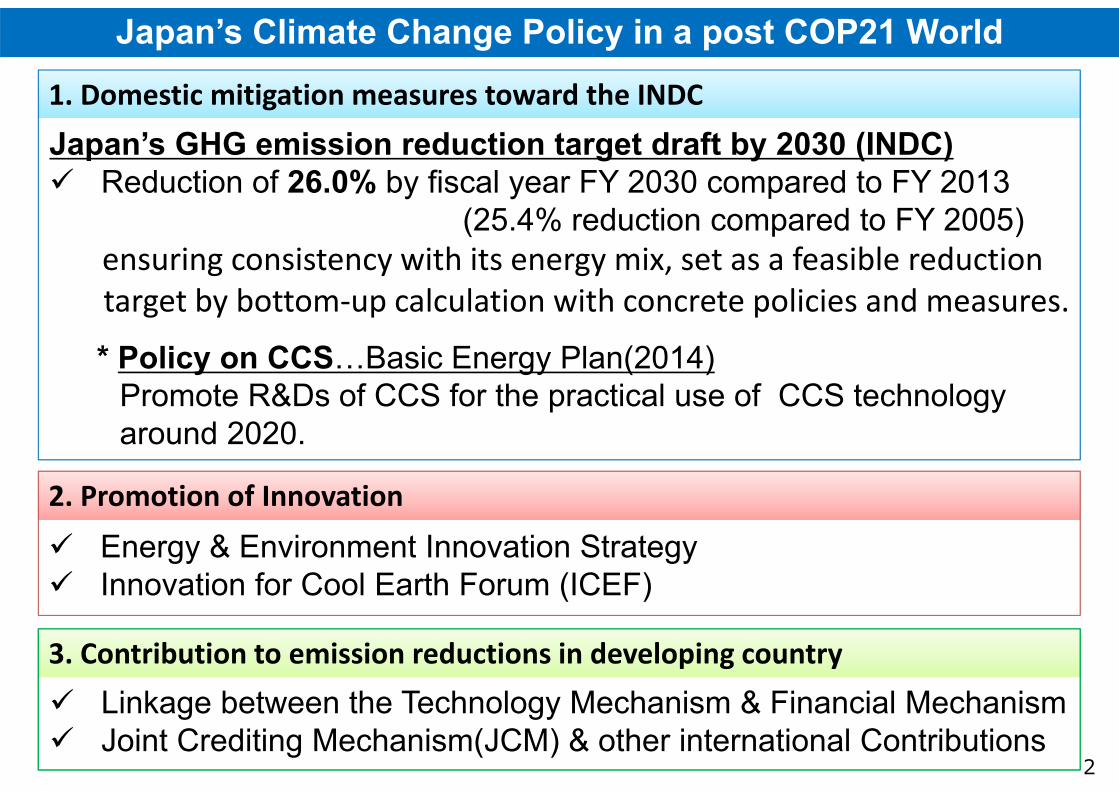
Japan’s Climate Change Policy in a post COP21 World
1. Domestic mitigation measures toward the INDC1. Domestic mitigation measures toward the INDC
2. Promotion of Innovation2. Promotion of Innovation
3. Contribution to emission reductions in developing country 3. Contribution to emission reductions in developing country
Japan’s GHG emission reduction target draft by 2030 (INDC) Reduction of 26.0% by fiscal year FY 2030 compared to FY 2013
(25.4% reduction compared to FY 2005) ensuring consistency with its energy mix, set as a feasible reduction target by bottom‐up calculation with concrete policies and measures.
* Policy on CCS…Basic Energy Plan(2014)Promote R&Ds of CCS for the practical use of CCS technology around 2020.
Energy & Environment Innovation Strategy Innovation for Cool Earth Forum (ICEF)
Linkage between the Technology Mechanism & Financial Mechanism Joint Crediting Mechanism(JCM) & other international Contributions
AA
Projects / FY 2015 2016 2017 2018 2019 2020~
A
Con-struction
CO2 Injection0.1 ~ 0.2 Mt/year
Post Injection Monitoring
R&Ds(2) CO2 Capture Technologies
TomakomaiDemo Pj.
Practical use of
CCS tech.
Drilling Exploration wells
CCS Site Survey
Geological Survey
Overview of CCS Projects in Japan
A(1) Safety Evaluation Technologies
Verifying Safety Evaluation Technologies
Cost Reduction
Identifying CO2 Storage Site
Achieving Operation Abilities
Confirming CCS safety
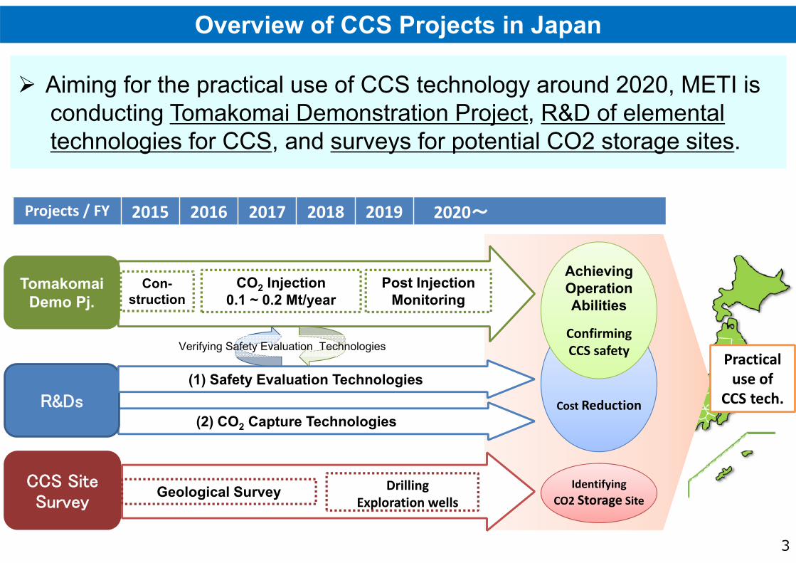
Aiming for the practical use of CCS technology around 2020, METI isconducting Tomakomai Demonstration Project, R&D of elementaltechnologies for CCS, and surveys for potential CO2 storage sites.
Aiming for the practical use of CCS technology around 2020, METI isconducting Tomakomai Demonstration Project, R&D of elementaltechnologies for CCS, and surveys for potential CO2 storage sites.
3
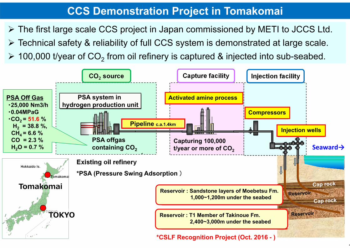
Pipeline c.a.1.4km
4
CCS Demonstration Project in Tomakomai
TOKYO
Tomakomai
Seaward→
Reservoir : Sandstone layers of Moebetsu Fm.1,000~1,200m under the seabed
Reservoir : T1 Member of Takinoue Fm.2,400~3,000m under the seabed
PSA offgas containing CO2
PSA system in hydrogen production unit
Capturing 100,000 t/year or more of CO2
Activated amine process
Compressors
Injection wells
*PSA (Pressure Swing Adsorption )
The first large scale CCS project in Japan commissioned by METI to JCCS Ltd. Technical safety & reliability of full CCS system is demonstrated at large scale. 100,000 t/year of CO2 from oil refinery is captured & injected into sub-seabed.
The first large scale CCS project in Japan commissioned by METI to JCCS Ltd. Technical safety & reliability of full CCS system is demonstrated at large scale. 100,000 t/year of CO2 from oil refinery is captured & injected into sub-seabed.
PSA Off Gas・25,000 Nm3/h・0.04MPaG・CO2 = 51.6 %
H2 = 38.8 %,CH4 = 6.6 %CO = 2.3 %H2O = 0.7 %
*CSLF Recognition Project (Oct. 2016 - )
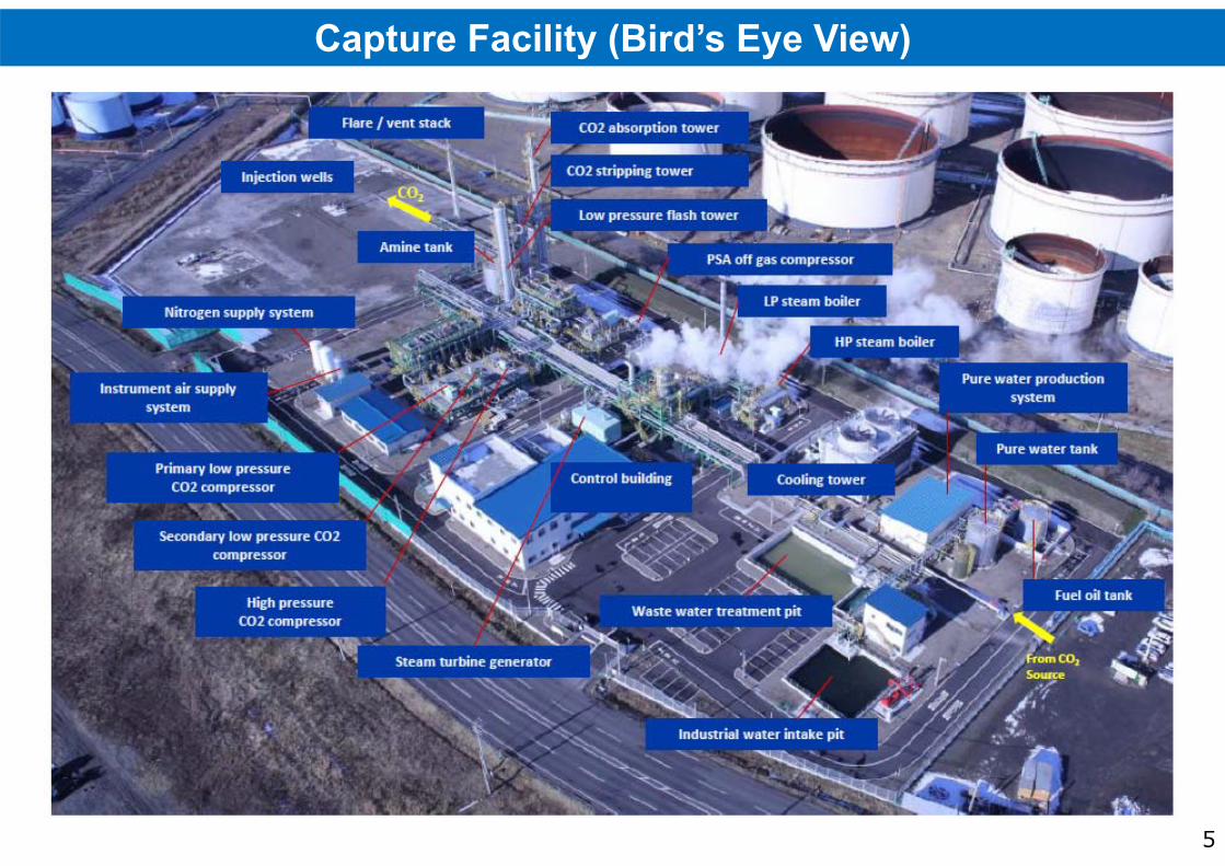
産業技術環境局 環境調和産業・技術室03-3501-9271Capture Facility (Bird’s Eye View)
5
From CO2source
CO2
産業技術環境局 環境調和産業・技術室03-3501-9271Schedule & Progress of Tomakomai CCS Project
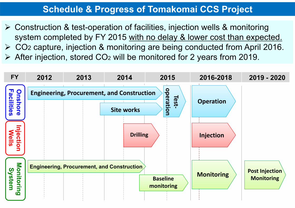
Construction & test-operation of facilities, injection wells & monitoring system completed by FY 2015 with no delay & lower cost than expected.
CO2 capture, injection & monitoring are being conducted from April 2016. After injection, stored CO2 will be monitored for 2 years from 2019.
Construction & test-operation of facilities, injection wells & monitoring system completed by FY 2015 with no delay & lower cost than expected.
CO2 capture, injection & monitoring are being conducted from April 2016. After injection, stored CO2 will be monitored for 2 years from 2019.
Onshore
FacilitiesM
onitoringSystem
InjectionW
ells
FY 2012 2013 2014 2015 2016-2018 2019 - 2020
Engineering, Procurement, and Construction
Engineering, Procurement, and Construction
Post InjectionMonitoring
Site works
Drilling
Baselinemonitoring
Test‐operation
Injection
Monitoring
Operation
7
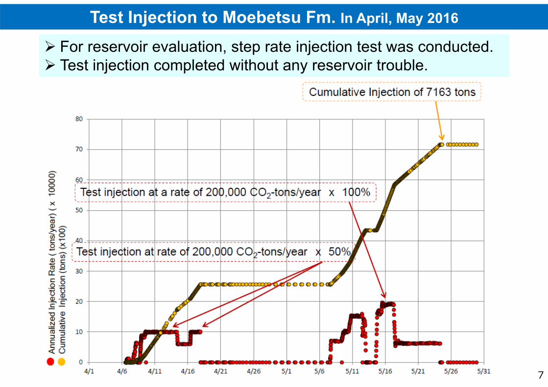
Test Injection to Moebetsu Fm. In April, May 2016
For reservoir evaluation, step rate injection test was conducted. Test injection completed without any reservoir trouble. For reservoir evaluation, step rate injection test was conducted. Test injection completed without any reservoir trouble.
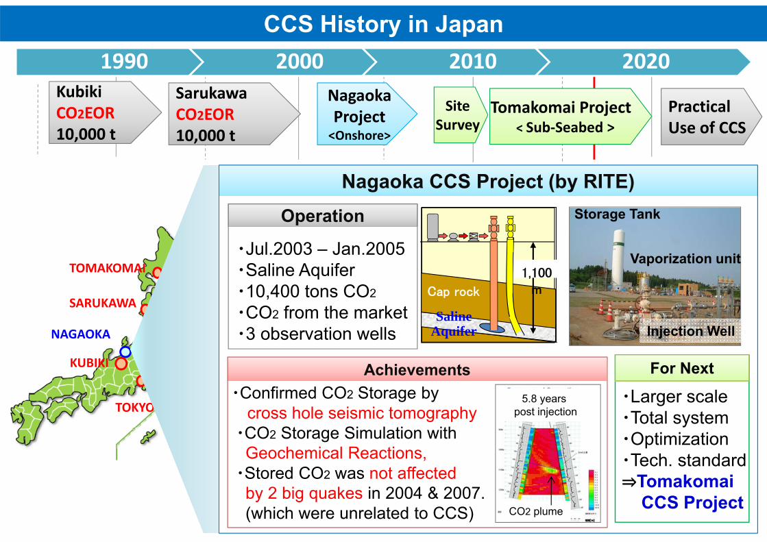
CCS History in Japan
NagaokaProject<Onshore>
Tomakomai Project< Sub‐Seabed >
1990 2000 2010 2020
PracticalUse of CCS
KubikiCO2EOR10,000 t
SarukawaCO2EOR10,000 t
TOKYO
NAGAOKA
TOMAKOMAI
SARUKAWA
KUBIKI
Nagaoka CCS Project (by RITE)Nagaoka CCS Project (by RITE)
Cap rock
SalineAquifer
1,100m
Vaporization unit
Injection Well
Storage Tank
・Jul.2003 – Jan.2005・Saline Aquifer・10,400 tons CO2
・CO2 from the market・3 observation wells
・Confirmed CO2 Storage bycross hole seismic tomography・CO2 Storage Simulation with
Geochemical Reactions,・Stored CO2 was not affected
by 2 big quakes in 2004 & 2007.(which were unrelated to CCS)
・Larger scale・Total system・Optimization・Tech. standard⇒Tomakomai
CCS Project
For NextAchievementsAchievements
Operation
SiteSurvey
5.8 years post injection
CO2 plume
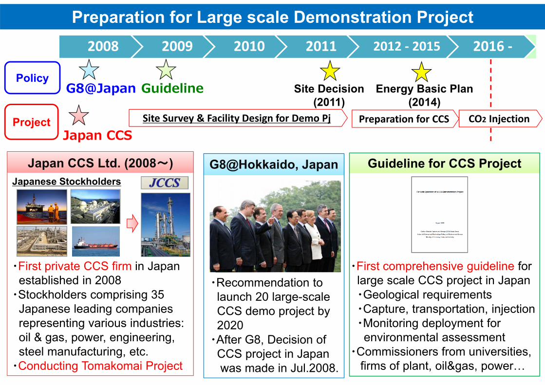
Preparation for Large scale Demonstration Project
・Recommendation to launch 20 large-scale CCS demo project by2020・After G8, Decision of
CCS project in Japan was made in Jul.2008.
・First private CCS firm in Japanestablished in 2008・Stockholders comprising 35
Japanese leading companies representing various industries:oil & gas, power, engineering, steel manufacturing, etc.・Conducting Tomakomai Project
・First comprehensive guideline forlarge scale CCS project in Japan・Geological requirements・Capture, transportation, injection・Monitoring deployment for
environmental assessment・Commissioners from universities,
firms of plant, oil&gas, power…
2008 2009 2010 2011 2012 ‐ 2015 2016 ‐
Japan CCS
G8@Japan Guideline
G8@Hokkaido, JapanG8@Hokkaido, JapanJapan CCS Ltd. (2008~)Japan CCS Ltd. (2008~) Guideline for CCS ProjectGuideline for CCS Project
Site Survey & Facility Design for Demo Pj Preparation for CCS
Japanese Stockholders
CO2 Injection
Policy
Project
Energy Basic Plan(2014)
Site Decision(2011)

10
Site Selection (2008~2011)
・Non structure・Saline Aquifer・Onshore・Survey well drilling→Low Permeability
・Depleted Gas Reservoir・CO2 from IGCC・Offshore & Pipeline・Quitted due to The Great
East Japan Earthquake in 2011
・Structure &Non structure type・Saline Aquifer・CO2 From Refinery・Onshore & ERD
Decision of Site atTechnical Committee
Site Selection Process
Test well Drilling
Adopted by Committee
TomakomaiTomakomai
Kita-KyushuKita-Kyushu Nakoso-Iwaki OkiNakoso-Iwaki Oki
Seismic Survey
Geological Study・Existing Site Data・Seismic Survey・Survey Well
Facility Design・Capture・Transportation・Injection System・Monitoring items
Public Acceptance
Reservoir Study・Geological modeling・Reservoir Characterization
11
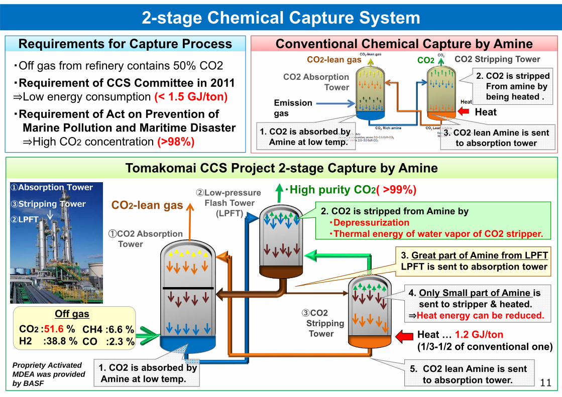
2-stage Chemical Capture System
・Off gas from refinery contains 50% CO2・Requirement of CCS Committee in 2011⇒Low energy consumption (< 1.5 GJ/ton)・Requirement of Act on Prevention of
Marine Pollution and Maritime Disaster⇒High CO2 concentration (>98%)
Requirements for Capture ProcessRequirements for Capture Process Conventional Chemical Capture by AmineConventional Chemical Capture by Amine
③Stripping Tower
②LPFT
①Absorption Tower
Tomakomai CCS Project 2-stage Capture by AmineTomakomai CCS Project 2-stage Capture by Amine
2. CO2 is stripped from Amine by ・Depressurization ・Thermal energy of water vapor of CO2 stripper.
②Low-pressure Flash Tower
(LPFT)
CO2 :51.6 %H2 :38.8 %
Off gas
①CO2 AbsorptionTower
1. CO2 is absorbed byAmine at low temp.
3. CO2 lean Amine is sentto absorption tower
1. CO2 is absorbed byAmine at low temp.
・High purity CO2( >99%)
③CO2 StrippingTower
CO2-lean gas
CH4 :6.6 %CO :2.3 %
Heat … 1.2 GJ/ton(1/3-1/2 of conventional one)
3. Great part of Amine from LPFTLPFT is sent to absorption tower
Propriety Activated MDEA was provided by BASF
5. CO2 lean Amine is sentto absorption tower.
Heat
4. Only Small part of Amine is sent to stripper & heated.
⇒Heat energy can be reduced.
CO2CO2-lean gas
Emissiongas
CO2 AbsorptionTower
2. CO2 is strippedFrom amine bybeing heated .
CO2 Stripping Tower
12
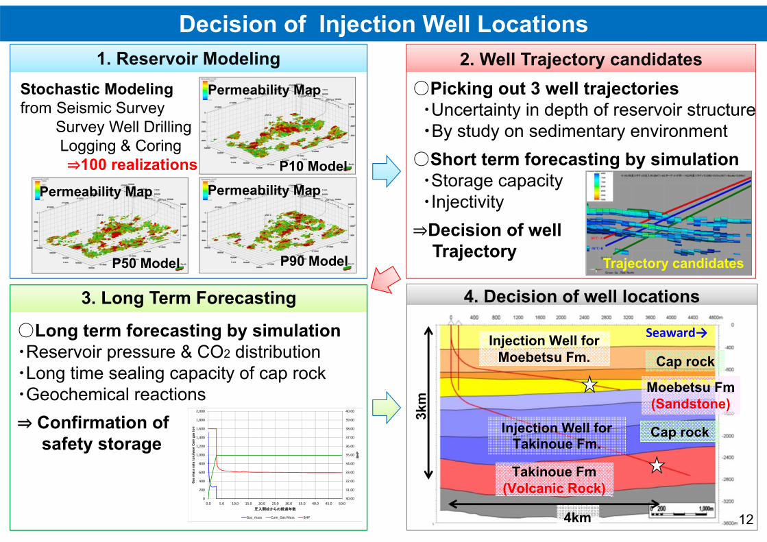
Decision of Injection Well Locations
○Picking out 3 well trajectories ・Uncertainty in depth of reservoir structure ・By study on sedimentary environment
○Short term forecasting by simulation・Storage capacity・Injectivity⇒Decision of well
Trajectory
○Long term forecasting by simulation・Reservoir pressure & CO2 distribution・Long time sealing capacity of cap rock・Geochemical reactions⇒ Confirmation of
safety storage
Stochastic Modelingfrom Seismic Survey
Survey Well DrillingLogging & Coring⇒100 realizations
30.00
31.00
32.00
33.00
34.00
35.00
36.00
37.00
38.00
39.00
40.00
0
200
400
600
800
1,000
1,200
1,400
1,600
1,800
2,000
0.0 5.0 10.0 15.0 20.0 25.0 30.0 35.0 40.0 45.0 50.0
BHP
Gas m
ass rate to
n/year Cum
gas to
n
圧入開始からの経過年数
Gas_mass Cum_Gas Mass BHP
Permeability Map
P10 Model
4km
4. Decision of well locations4. Decision of well locations
Permeability Map
P50 Model
Permeability Map
P90 Model Trajectory candidates
1. Reservoir Modeling1. Reservoir Modeling 2. Well Trajectory candidates2. Well Trajectory candidates
3. Long Term Forecasting3. Long Term Forecasting
Injection Well for Moebetsu Fm.
Injection Well for Takinoue Fm.
Cap rock
Moebetsu Fm(Sandstone)
Cap rock
Takinoue Fm(Volcanic Rock)
3km
Seaward→

13
Drilling & Completion DesignChallengesChallenges
○ Highly deviated well⇒Danger of drill pipe stuck
○ Unconsolidated Reservoir⇒Danger of collapse, sand trouble
○ CO2 Injection⇒Countermeasures for corrosion
AnalysesAnalyses
○ Particle size distribution by survey well core
Extended Reach DrillingExtended Reach Drilling
○ Overbalance pressure controlto avoid Bore hole Collapse
○ Lubricant, Synthetic mud & Casingdrive system to avoid stacking
○ Spotting High viscosity mudfor effective bore hole cleaning
Sand ControlSand Control・Wire rap screen ◎Avoid sand trouble◎Keep good injectivity◎Low operation risk・Gravel pack・Stand alone・Expandable sand screen
○ CO2 corrosion resistant steelcontaining Cr for Casing & Tubing
○ CO2 resistant Cementing
Selection of MaterialsSelection of Materials
○ Wellbore Stability Analysis・Uniaxial compression test・Rock strength evaluation from Logs・Perforation stability analysis
Wire rap screen
○ Corrosion test in high press, Stress Test…
Corrosion TestParticle size distribution analysis

14
Injection well for Moebetsu Formation
KOPdepth
Verticaldepth
Horizontalreach
Maximuminclination
Totaldepth
240m 1,188m 3,058m 83° 3,650m
Perforated liner covered by screensat injection interval
Perforated liner Screen
PT sensorCO2 resistant cement
CO2 corrosion resistantsteel (Chrome)
Drilling :12th March 2015 ‐ 22nd June 2015
CO2 resistant cement
Tubing‐Retrievable Safety Valve(TRSV)
TRSV
Quaternary
Moebetsu Fm(Mudstone)
Mukawa Fm
464mMD458mVD
1,525mMD864mVD
2,395mMD970mVD
Moebetsu Fm(Sandstone)
TD 3,650mMD1,188mVD
15
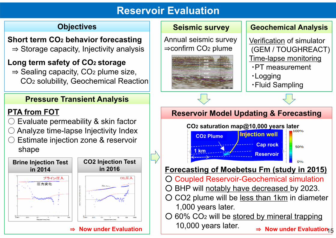
Reservoir Evaluation
Verification of simulator(GEM / TOUGHREACT)Time-lapse monitoring・PT measurement・Logging・Fluid Sampling
Short term CO2 behavior forecasting⇒ Storage capacity, Injectivity analysis
Long term safety of CO2 storage⇒ Sealing capacity, CO2 plume size,
CO2 solubility, Geochemical Reaction
ObjectivesObjectives Seismic surveySeismic survey
Pressure Transient AnalysisPressure Transient Analysis
Geochemical AnalysisGeochemical Analysis
⇒ Now under Evaluation
PTA from FOT○ Evaluate permeability & skin factor○ Analyze time-lapse Injectivity Index○ Estimate injection zone & reservoir
shapeBrine Injection Test
in 2014Brine Injection Test
in 2014CO2 Injection Test
in 2016CO2 Injection Test
in 2016
Annual seismic survey⇒confirm CO2 plume
⇒ Now under Evaluation
Forecasting of Moebetsu Fm (study in 2015)○ Coupled Reservoir-Geochemical simulation○ BHP will notably have decreased by 2023.○ CO2 plume will be less than 1km in diameter
1,000 years later.○ 60% CO2 will be stored by mineral trapping
10,000 years later.
Reservoir Model Updating & ForecastingReservoir Model Updating & ForecastingCO2 saturation map@10,000 years later
Cap rock
Reservoir
Injection wellCO2 Plume
1 km
16
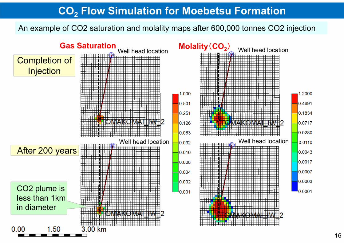
CO2 Flow Simulation for Moebetsu Formation
Completion of Injection
After 200 yearsWell head location
Well head locationGas Saturation Well head location
Well head location
Molality(CO2)
An example of CO2 saturation and molality maps after 600,000 tonnes CO2 injectionAn example of CO2 saturation and molality maps after 600,000 tonnes CO2 injection
CO2 plume is less than 1km in diameter
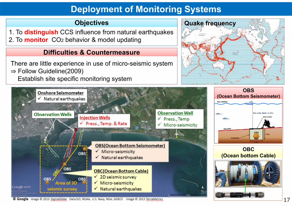
OBS(Ocean Bottom Seismometer)
OBS(Ocean Bottom Seismometer)
産業技術環境局 環境調和産業・技術室03-3501-9271Deployment of Monitoring Systems
1. To distinguish CCS influence from natural earthquakes2. To monitor CO2 behavior & model updating
There are little experience in use of micro-seismic system⇒ Follow Guideline(2009)
Establish site specific monitoring system
Difficulties & CountermeasureDifficulties & Countermeasure
ObjectivesObjectives Quake frequency
17
OBC(Ocean bottom Cable)
OBC(Ocean bottom Cable)

産業技術環境局 環境調和産業・技術室03-3501-9271Publication of Monitoring Data
18
Raw data from systemsRaw data from systems
Publication for PAPublication for PA
Processing SchemeProcessing Scheme
Events DetectionEvents Detection TomakomaiCity officeInjection(Apr.2016-)Baseline observation

19
Earthquake Information Announced by the Japan Meteorological Agency
Time & date 14:21:28(JST) 16 June, 2016
Epicenter Lat. 41°56.9′NLon. 140°59.2′E
Depth 11 km
Magnitude 5.3
Seismic Intensity at near epicenter and Tomakomai
Lower 6 and 2on Japanese seismic scale
approx. Ⅷ and approx. Ⅱ‐Ⅲon Mercalli intensity scale
X
Y
Z
Observation record of Onshore Seismometer
Pressure (M
pa)
Tempe
rature
(deg.C)
Injection well for Moebetsu Fm. Average Pressure: 9.56MPa (at 930m in depth)
Injection well for Moebetsu Fm. Average Temperature: 38.0 (at 930m in depth)
Distance of approx.90km
This earthquake had no influence on temperature and pressure of the cap rock strata.
Monitoring Area
Borehole Pressure
Borehole Temperature
TomakomaiThree components
30sec.
An example of Natural Earthquake after CO2 injection

Gaseous CO2CO2>99%
Remaining gasfor fuel
Injection well for Moebetsu Fm.М
From CO2source
CO2 Capturelow pressure compression
Low‐pressure boiler
PSA off gas
Compressor for PSA off gas
High‐pressure boiler
Injection well for Takinoue Fm.
Max. 9.3 MPa
Max. 22.8 MPa
Amine reboiler
Steam turbine for power generation
CO2
CO2CO2
Gas Business Act
High Pressure Gas Safety Act
Industrial safety and Health Act
Electricity Business Act
Act for the Prevention of Marine Pollution and Maritime Disasters
Note: Fire Service Act is applied to the facilities related Amine and Bunker A.
Process Flow and Applicable Laws
Conventional industrial laws are applicable for the facilities.Conventional industrial laws are applicable for the facilities.
high pressure compression
Applicable LawsApplicable Laws
20
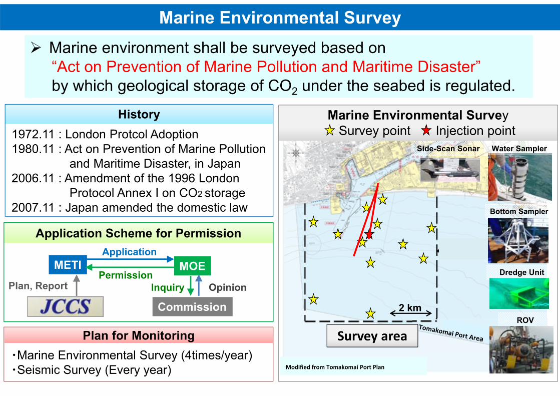
Marine environment shall be surveyed based on “Act on Prevention of Marine Pollution and Maritime Disaster” by which geological storage of CO2 under the seabed is regulated.
Marine environment shall be surveyed based on “Act on Prevention of Marine Pollution and Maritime Disaster” by which geological storage of CO2 under the seabed is regulated.
Modified from Tomakomai Port Plan
Side-Scan Sonar Water Sampler
Dredge Unit
ROV
Marine Environmental Survey
Survey area
Bottom Sampler
HistoryHistory
・Marine Environmental Survey (4times/year)・Seismic Survey (Every year)
Plan for MonitoringPlan for Monitoring
Application Scheme for PermissionApplication Scheme for Permission
METI MOE
Commission
Plan, Report
Application
PermissionInquiry Opinion
Marine Environmental SurveySurvey point Injection point
Marine Environmental SurveySurvey point Injection point1972.11 : London Protcol Adoption
1980.11 : Act on Prevention of Marine Pollutionand Maritime Disaster, in Japan
2006.11 : Amendment of the 1996 London Protocol Annex I on CO2 storage
2007.11 : Japan amended the domestic law
2 km
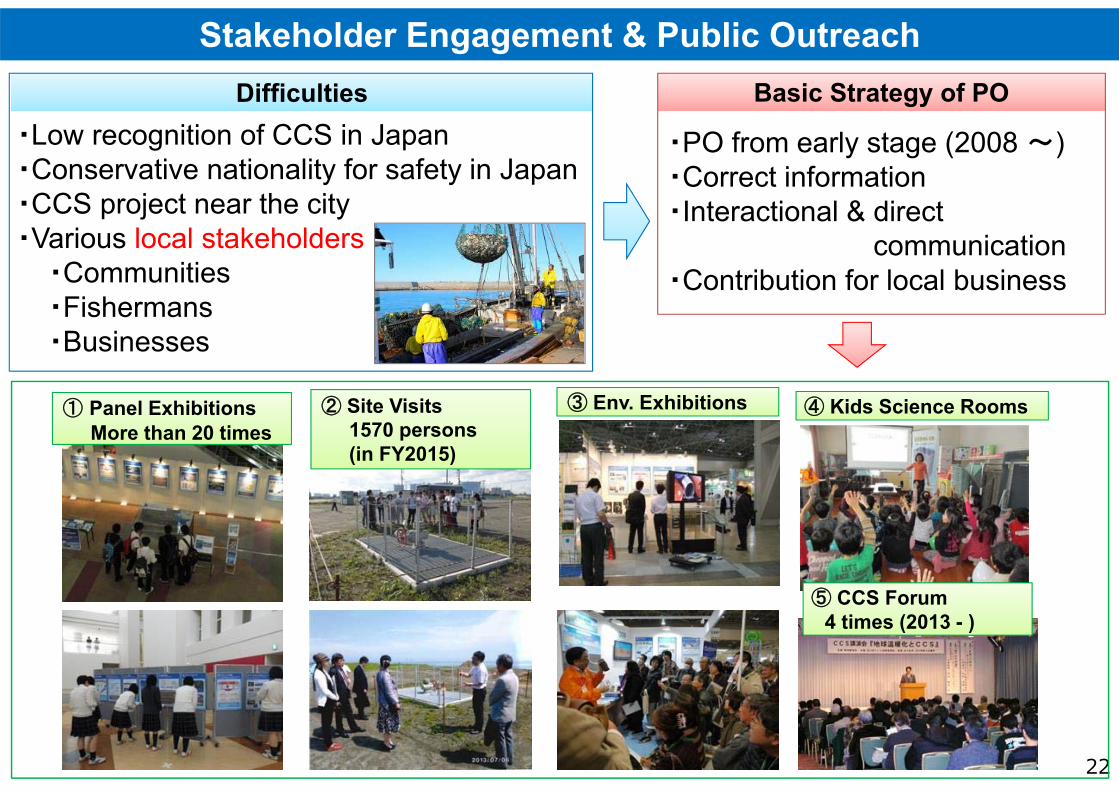
産業技術環境局 環境調和産業・技術室03-3501-9271Stakeholder Engagement & Public Outreach
22
④ Kids Science Rooms③ Env. Exhibitions
⑤ CCS Forum 4 times (2013 - )
・PO from early stage (2008 ~)・Correct information・Interactional & direct
communication・Contribution for local business
・Low recognition of CCS in Japan・Conservative nationality for safety in Japan・CCS project near the city・Various local stakeholders
・Communities・Fishermans・Businesses
② Site Visits1570 persons(in FY2015)
DifficultiesDifficulties Basic Strategy of POBasic Strategy of PO
① Panel ExhibitionsMore than 20 times
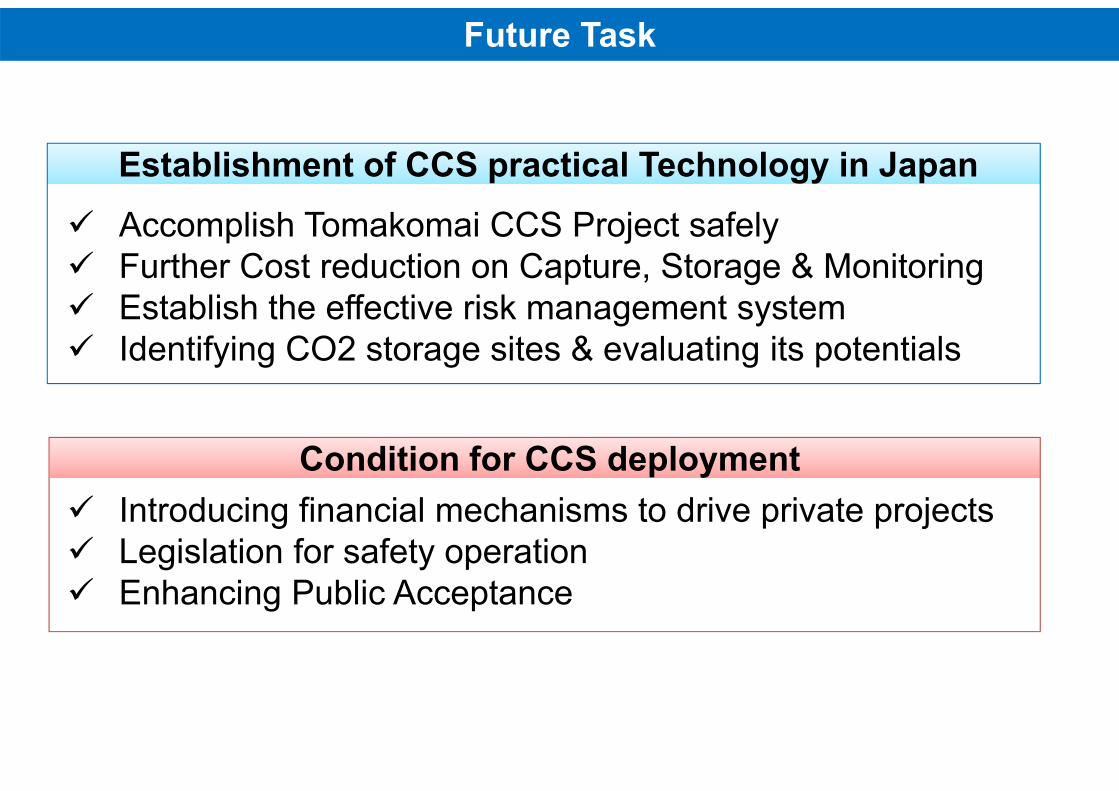
Future Task
Accomplish Tomakomai CCS Project safely Further Cost reduction on Capture, Storage & Monitoring Establish the effective risk management system Identifying CO2 storage sites & evaluating its potentials
Introducing financial mechanisms to drive private projects Legislation for safety operation Enhancing Public Acceptance
Establishment of CCS practical Technology in JapanEstablishment of CCS practical Technology in Japan
Condition for CCS deploymentCondition for CCS deployment
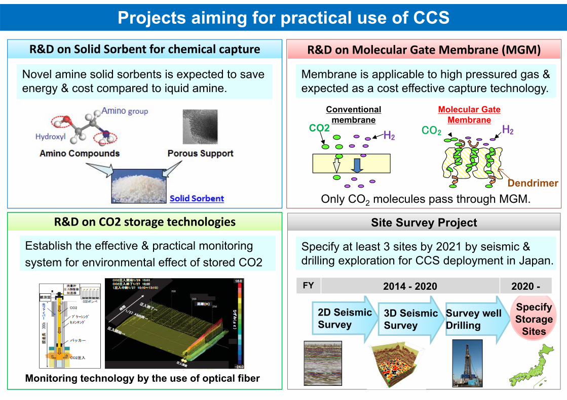
Dendrimer
Projects aiming for practical use of CCSR&D on Solid Sorbent for chemical captureR&D on Solid Sorbent for chemical capture R&D on Molecular Gate Membrane (MGM)R&D on Molecular Gate Membrane (MGM)
R&D on CO2 storage technologiesR&D on CO2 storage technologies Site Survey ProjectSite Survey Project
Specify at least 3 sites by 2021 by seismic &drilling exploration for CCS deployment in Japan.Specify at least 3 sites by 2021 by seismic &drilling exploration for CCS deployment in Japan.
Establish the effective & practical monitoringsystem for environmental effect of stored CO2Establish the effective & practical monitoringsystem for environmental effect of stored CO2
Novel amine solid sorbents is expected to save energy & cost compared to iquid amine.Novel amine solid sorbents is expected to save energy & cost compared to iquid amine.
Membrane is applicable to high pressured gas &expected as a cost effective capture technology.Membrane is applicable to high pressured gas &expected as a cost effective capture technology.
2D SeismicSurvey
3D SeismicSurvey
Survey wellDrilling
SpecifyStorage
Sites
FY 2014 - 2020 2020 -
CO2 H2CO2H2
Conventionalmembrane
Molecular GateMembrane
Only CO2 molecules pass through MGM.
Monitoring technology by the use of optical fiber