presentation of a system for aut on pipelines and penstock ... · aut on pipelines and penstock the...
TRANSCRIPT

Presentation of a system forAUT on Pipelines and Penstock
THE PIPERUNNER
Authors: - WOLF Stéphane MISTRAS GROUP SA
- DELEMONTEZ Jérôme ELECTRICITE DE FRANCE (EDF)
Direction Technique Générale (DTG)
11th ECNDT
PRAGUE 2014
October 9, 2014

SUMMARY
- About our companies
- What is AUT
- Summary of NDT method
- Codes and standards
- History and development of the systems
- Qualification stage of the system
- Implementation on site
- Conclusion
ABOUT MISTRAS GROUPand
EDF DTG
MISTRAS GROUP
- Established in 1968
- 13 sites in France ( + implanting worldwide)
- 400 agents in France ( 5000 worldwide)
- Missions:
- Systems and services provider
- NDT
- Software, Hardware
- Products and systems
- Training
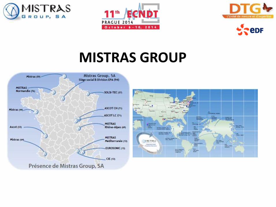
MISTRAS GROUP

EDF DTG(Direction Technique Générale)
- Established in 1946
- 5 sites in France
- 650 agents
- Missions:
- Ensure the safety of the
exploitation and the quality of new
hydraulic components
- Guarantee the performance and
optimization of power generation
- Ensure respect for the
environment

WHAT IS AUT ?
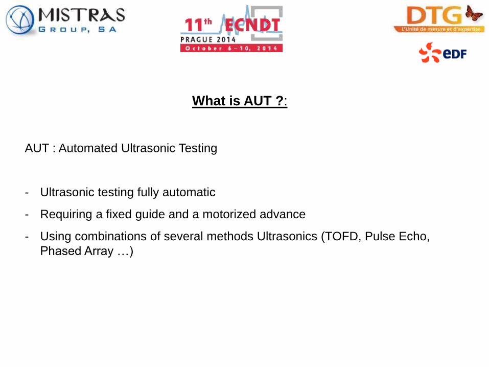
What is AUT ?:
AUT : Automated Ultrasonic Testing
- Ultrasonic testing fully automatic
- Requiring a fixed guide and a motorized advance
- Using combinations of several methods Ultrasonics (TOFD, Pulse Echo,
Phased Array …)

Benefit of AUT:
- Significant reduction of testing duration (testing 1 in single acquisition)
- Instant results
- Reproductibility of testing (low influence of the operator)
- Increased probability of detection
- Accurate positioning and sizing of indications allowing monitoring over time
- Used in lieu of radiography (no radiation allowing coactivity on site) and
allow to reduce the amont of RT during the complete manufacturing process.
SUMMARY OF NDT METHOD
TOFD(Time of Flight Diffraction)
TOFD method of ultrasonic inspection is a very sensitive and accurate method for non destructive testing of welds for defects. TOFD is a computerized system that was invented in the UK in the 1970s for the nuclear industry by Dr. Maurice
Silk. The use of TOFD enabled crack sizes to be measured accurately
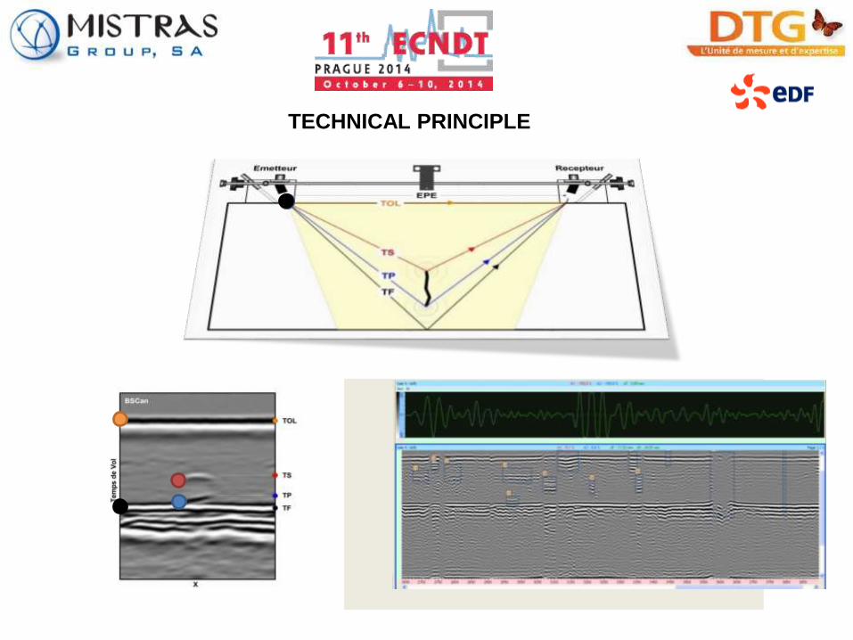
TECHNICAL PRINCIPLE

PHASED ARRAY
PA ( Phased array) is an advanced method of Ultrasonic that has applications
in industrial NDT, originally pioneered by Albert Macoyski of Stanford
University
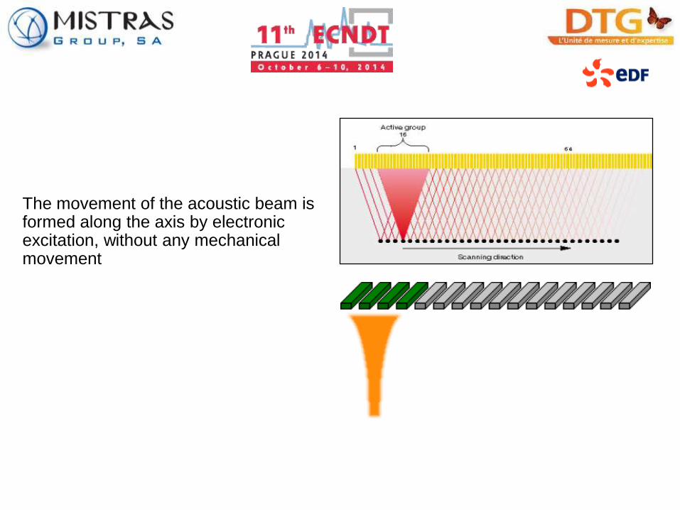
The movement of the acoustic beam is formed along the axis by electronic excitation, without any mechanical movement

Straight beam Angle beam Focused straight
beam
Focused angle
beam
CODES AND STANDARDS

PHASED ARRAY:
- NF EN ISO 13588 : Used of automated phased array technology
TOFD :
-NF EN 583-6 : Time of flight diffraction technique as a method for
detection and sizing of discontinuities
-NF EN ISO 10863 : Use of time of fligth diffraction technique
(TOFD)
-NF EN ISO15626 : Acceptance criteria for the time of flight
diffraction inspection technique
AUT :
-CPC IH.X.DT.10033 (EDF) : Specification of common requirements
+ specification for the validation of "AUT TOFD" system and RRC-
MH 3rd edition
-SG-DIS-PNE-C-003 (GRT GAZ): General specification for the
technical qualification of an automated control system for ultrasonic
examination of girth welds on site.

HISTORY AND DEVELOPMENT OF THE
SYSTEMS

The first AUT system called PIPERUNER designed by EUROSONIC (a
MISTRAS GROUP company) in 2008 was qualified by GRTGAZ to be used on
gas pipelines girth welds.
The combinaison of TOFD and Pulse Echo were used.
- Two probes (TOFD) for welded volume + HAZ
- Two probes (PE) for the root (dead zone of TOFD)
- Two probes (PE) for the cap (dead zone of TOFD)
- Four probes (PE) for transverse indication
TOTAL: 10 probes

PIPERUNNER « first evolution »
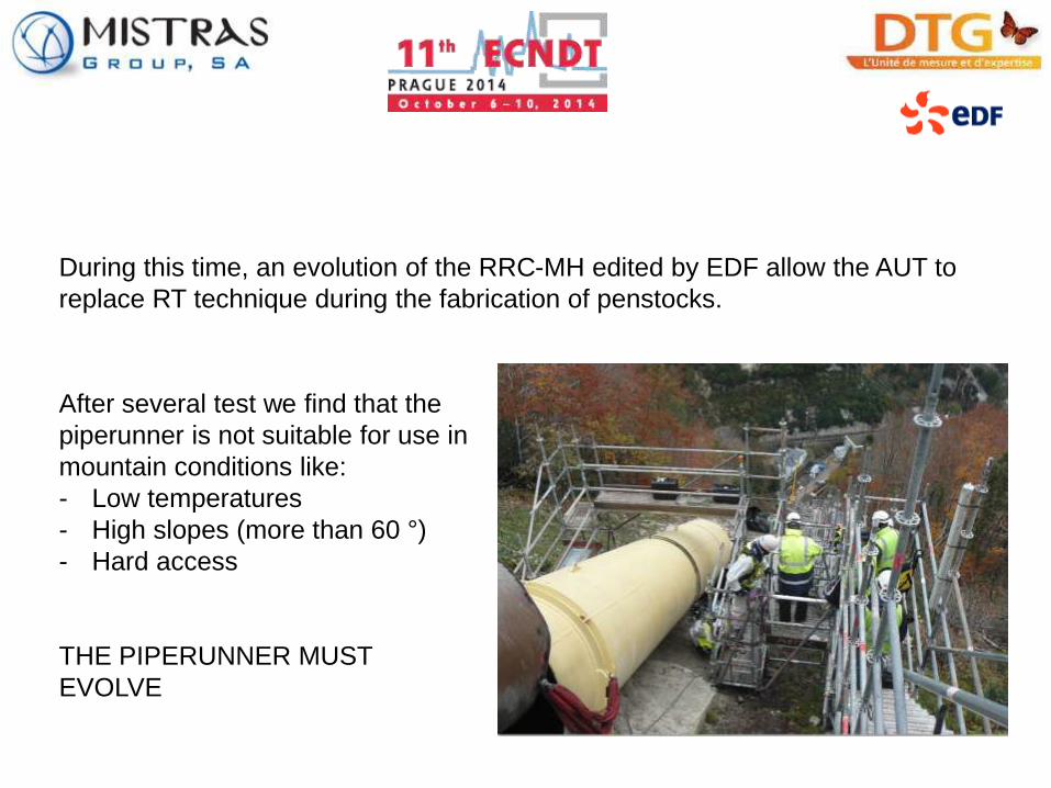
During this time, an evolution of the RRC-MH edited by EDF allow the AUT to
replace RT technique during the fabrication of penstocks.
After several test we find that the
piperunner is not suitable for use in
mountain conditions like:
- Low temperatures
- High slopes (more than 60 °)
- Hard access
THE PIPERUNNER MUST
EVOLVE

Evolution of the new Piperunner: In 2011 the new Piperunner is born
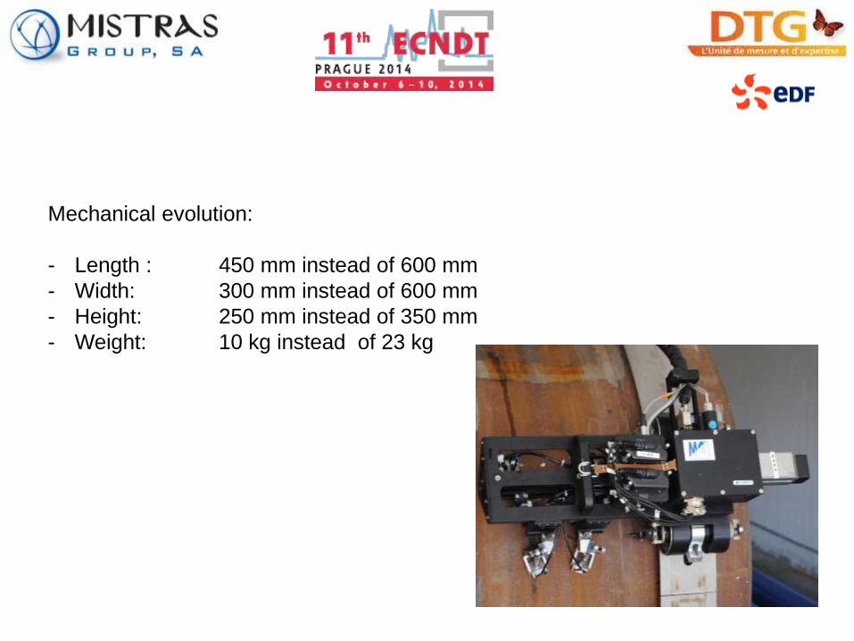
Mechanical evolution:
- Length : 450 mm instead of 600 mm
- Width: 300 mm instead of 600 mm
- Height: 250 mm instead of 350 mm
- Weight: 10 kg instead of 23 kg

Evolution of the control unit:
- Length : 250 mm instead of 500 mm
- Width: 160 mm instead of 500 mm
- Height: 80 mm instead of 500 mm
- Weight: 3 kg instead of 10 kg
- Power supply: Batteries instead of AC power

Ultrasonic evolutions:
The main evolution is the replacement of 4 pulse echo probes by 2 phased
probes: this allow to reduce the quantity of UT probes necessary to guarantee
100% covered area

Ultrasonic evolutions:
.

QUALIFICATION STAGE OF THE SYSTEMS
ACCORDING EDF SPECIFICATIONS
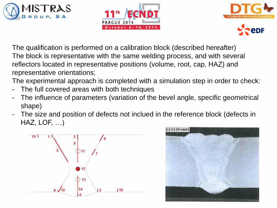
The qualification is performed on a calibration block (described hereafter)
The block is representative with the same welding process, and with several
reflectors located in representative positions (volume, root, cap, HAZ) and
representative orientations;
The experimental approach is completed with a simulation step in order to check:
- The full covered areas with both techniques
- The influence of parameters (variation of the bevel angle, specific geometrical
shape)
- The size and position of defects not inclued in the reference block (defects in
HAZ, LOF, …)

Results of CIVA TOFD simulation ( with and without lateral Wave and
backwall echo) : no-detected defects in dead TOFD zones

Results of CIVA PA simulation ( LOF )
Cap PA examination configuration

Configuration in flat conditions Configuration acquisitions on the ceiling
All reflectors must be detected and correctly measured (position, length, depth)
Coupling have to be proved during the full acquisitions for TOFD probe and with
specific PA focal law.

IMPLEMENTATION ON SITE
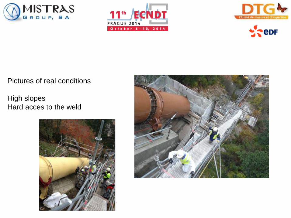
Pictures of real conditions
High slopes
Hard acces to the weld

Pictures of real conditions
Low space beetween the pipe and
the floor
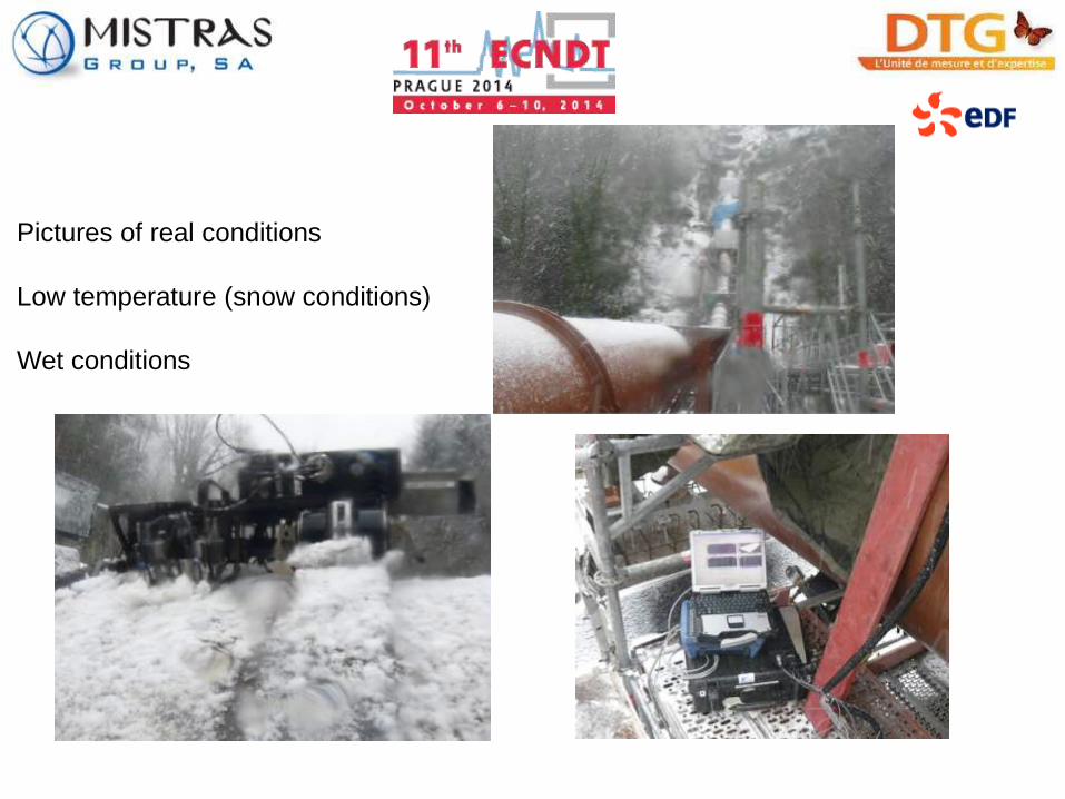
Pictures of real conditions
Low temperature (snow conditions)
Wet conditions
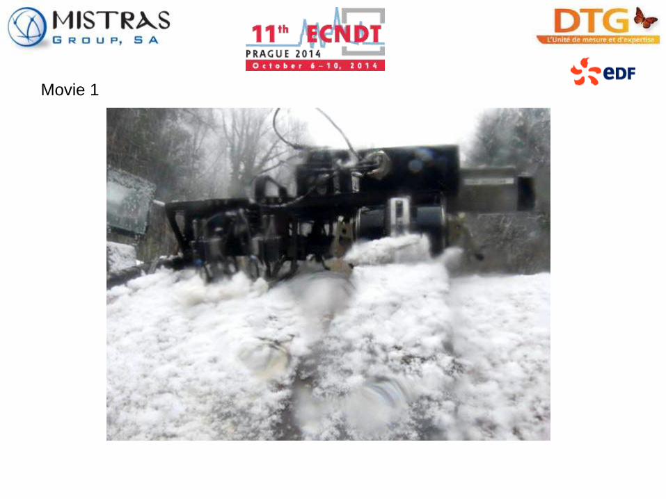
Movie 1

Movie 2
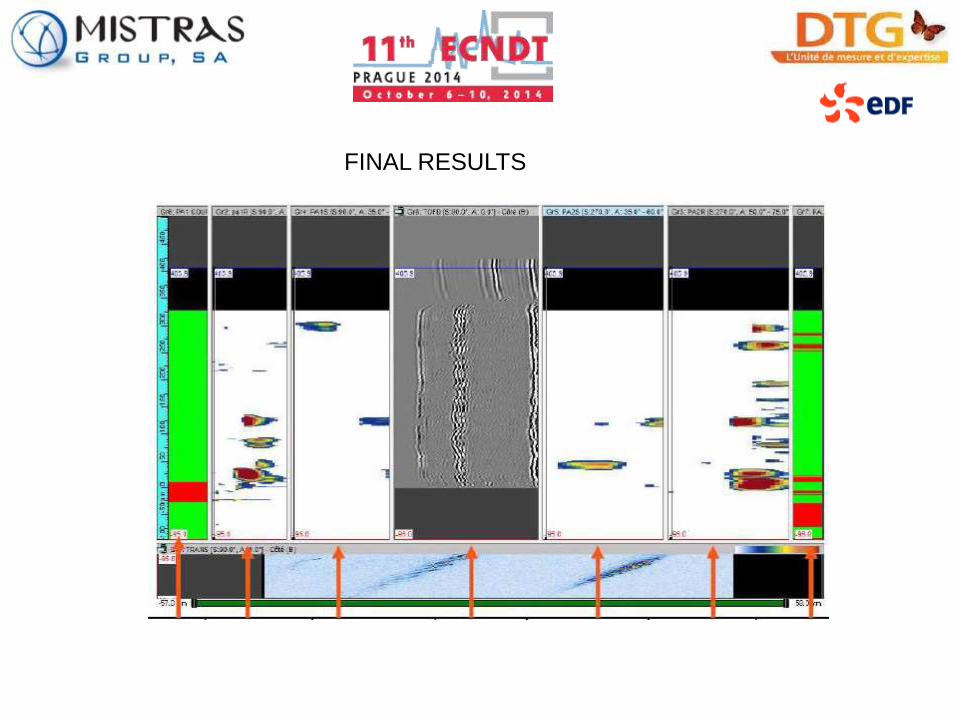
FINAL RESULTS

FINAL RESULTS
Each chanel can be analysed independetly
Phased Array

FINAL RESULTS
Each chanel can be analysed independetly
TOFD
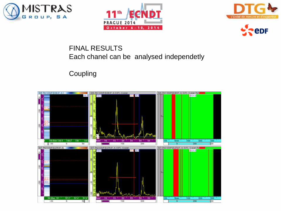
FINAL RESULTS
Each chanel can be analysed independetly
Coupling

CONCLUSION

•AUT-TOFD with additional PA proved to be a good and reliable solution to reduce
the part of RT during the manufacturing process,
•adapted development was necessary to suit the real conditions of the work,
•steps of qualification were necessary to prove the capability of the systems
regarding NDT performances and implementation,
•simulation help to reduce the quantity of mock-ups necessary for the qualification,
•AUT-TOFD with additional PA is now a EDF standard (RRC-MH) for the NDT
during the penstock manufacturing and construction work (new/new welds
examination),
•however RT is still necessary for particular conditions such as new/old welding
examination.
THANK YOU FOR YOUR ATTENTION
PLEASE VISIT OUR STAND