presentation to ieee p802.3ap backplane ethernet … p802.3ap backplane ethernet task force...
TRANSCRIPT

Presentation to IEEE P802.3ap Backplane Ethernet Task ForceSeptember 2004 Working Session
Title: Simulation Results on Proposed Signaling Ad-hoc Test Channels
Source: Joe Abler [email protected] IBM Microelectronics
Date: September 24, 2004
Abstract: This contribution provides simulation results of performance analysis across the set of test channels proposed for use by the signaling ad-hoc. Simulations are performed using a full function simulator which constructs a complete end to end transceiver-package-channel-package-transceiver model.
1

IEEE P802.3ap Backplane Ethernet Task Force September, 2004
Simulation Approach
Use internally available IBM simulator for analysis of Tyco channelsTool models advanced equalization approaches including NRZ/DFE & PAM4 architecturesTool and associated models have gone through extensive hardware to model correlation
NRZ/DFE designs operating up to 6.25GbpsHardware to model correlation across process, temperature, & voltage
Appropriately configure simulator for analysis at 10.3GbpsConfigure simulator for worst case parameters proposed to 10G EoBP standard
Include analysis of 2 representative package typesOrganic & flip chip plastic
Perform analysis across full set of test channels proposed to signaling ad-hocInclude all cross-talk channels in analysisEvaluate range of FFE/DFE architectures which would support the various channels
Summary
2
IEEE P802.3ap Backplane Ethernet Task Force September, 2004
Validation of Existing DFECDR Simulator
Feature rich simulator developed over several yearsDeveloped for 6.25Gbps serdes architecture validation
Required for analysis of advanced equalization techniques & CDR architectures
Continually updated with additional features and improved coverage of secondary performance effectsUsed for development of multiple link types within IBM Research & Development community
Distributed as customer tool for system level verificationToday used by dozens of customers evaluating a variety of applications
NRZ/DFE architecture fully validated in hardware6.25 Gbps 4-tap FFE, 5-tap DFE based serdes in IBM 0.13um technology available since last yearSystem level performance (BER<10-15) demonstrated on a multitude of channel types
Severely attenuated channels in the range of 30dB to 35dB lossChannels in the range of 25dB to 30dB loss along with severe discontinuities or high crosstalk
Simulator fully correlated to hardware across corner conditionsSimulator includes extracted parasitics from design base
Extractions across nominal, worst case, and best case process variationExtractions across range of equalizer & launch voltage settings
All serdes designs are built & characterized with split lot process corners3-way threshold voltage (Vt) & 5-way delta-L (poly length) splitsFull characterization performed across process, temperature, & voltage
Simulator successfully correlated to hardware characterization Across best case, worst case, and nominal conditionsDone for multiple design points and serdes architectures
3
IEEE P802.3ap Backplane Ethernet Task Force September, 2004
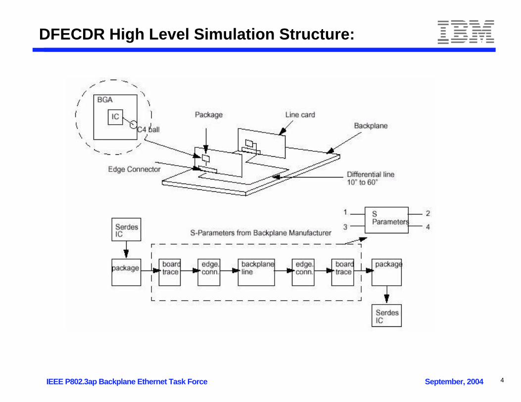
DFECDR High Level Simulation Structure:
4

IEEE P802.3ap Backplane Ethernet Task Force September, 2004
High Level Simulation Structure:
ClockGeneration
Transmitter/FIR
THRU
(S-parameters)S Receiver/
CDRChannel Clock
Generation
Transmitter/FIR
NEXT
(S-parameters)ChannelTransmitter/
FIR
NEXT
(S-parameters)ChannelTransmitter/
FIR
NEXT
(S-parameters)ChannelTransmitter/
FIR
NEXT
(S-parameters)Aggressor S
Transmitter/FIR
FEXT
(S-parameters)ChannelTransmitter/
FIR
FEXT
(S-parameters)ChannelTransmitter/
FIR
FEXT
(S-parameters)ChannelTransmitter/
FIR
FEXT
(S-parameters)Aggressor S
dn
df
TCLK RIN
FEXT
NEXT
THRUTOUT RCLK
Up to 8?
Up to 8?
GlobalParameters:- Support BC,NC,WC- S-parameters: 4 port SE format (must define)
5
IEEE P802.3ap Backplane Ethernet Task Force September, 2004
Simulator Feature Summary
A complete end to end system model is constructedTransmitter model and termination network
including extracted parasitics for bc, nc, wc options
Package + C4 + module ball parasiticsChannel model S-parameter representation
Optional crosstalk aggressor S-parameter models
Package + C4 + module ball parasiticsFull receiver model
Receiver model and termination network, including extracted bc, nc, wc parasiticsAGC AmplifierDFE summing amplifiersComplete model of CDR algorithm
The tool includes simulation of the following performance detractors:Channel Impairments (DJ/ISI)
Derived directly from channel S-parameters
Circuit ImpairmentsSinusoidal Jitter (SJ): accounts for external SJ modulation as well as Tx DCD and system DJRandom Jitter (RJ): one sigma RJ term representing the RMS of Tx and Rx RJ.Amplitude Noise: one sigma RMS voltage noise referred to receiver inputMinimum Latch Overdrive: loss in eye opening due to latch overdrive (level resolution concern)
6
IEEE P802.3ap Backplane Ethernet Task Force September, 2004
Simulator Feature Summary...
The tool incorporates an algorithm to compute optimal FFE & DFE coefficientsBased on channel characteristicsOptimizes system performance in presence of crosstalk
Configuration of key system parameters to evaluate varied performance scenariosData coding
PRBS7, CJTPAT, JTPAT, CRPAT, RPAT, CSPAT, SPAT, ALT10 (1010..), Random 8B/10B, User specified...
Transceiver configurationBaud rateDriver level amplitudeFFE/DFE configuration
Optional coefficient override
Jitter controls RJ, SJ, amplitude noise, latch min overdrive, etc.
Runtime optionsRunlength, settle length, etc.
Numerous output plot options Frequency Response, Impulse Response, Eye diagram, NRZ eye, Horizontal and Vertical CDF, Phase rotator tracking, text performance summary
7

IEEE P802.3ap Backplane Ethernet Task Force September, 2004
Configuration for NRZ Simulations
Configure for worst case (expected) standard definitionLaunch amplitude set to minimum 800 mVpp Transmitter DJ set to maximum 0.15 UIppTransmitter RJ set to maximum 0.0107 UIrms (0.15UIpp @ 10-12 BER)Tx/Rx termination skewed to maximum tolerance 4040/6060 ohms
Conservatively model receiver implementationReceiver DJ in addition to termination parasitics 0.05 UIppReceiver RJ set to maximum 0.0107 UIrms (0.15UIpp @ 10-12 BER)
Approximate parasitics for worst case 12Gbps implementationUse nominal case parasitics from 6Gbps design in 0.13um technology
Extracted parasitics for 12Gbps implementation are not availableThese parasitics considered highly conservative relative to WC parasitics of 90nm 12Gbps design
Configure system parametersData rate: 10.3 GbpsReceiver offset: 200 ppmData pattern: RandomUse all cross talk channels for each test caseVary FFE/DFE configuration across runs
FFE2 as single post-cursorFFE3 & FFE4 includes a single pre-cursor
Run test suite across 2 package types (organic & flip chip plastic)10M bit simulation time per testcase
8

IEEE P802.3ap Backplane Ethernet Task Force September, 2004
Example Output
Tyco Channel Case #3 Organic packageFFE3/DFE5 Configuration
Without Crosstalk21.5% open @ BER 10-12
With Crosstalk17.6% open @ BER 10-12
-1.0 1.0-500E-3 0 500E-3-25
0
-22
-20
-17
-15
-12
-10
-7.5
-5.0
-2.5
0
BER DFE3T1-5 10.3Gb/s Tyco_Case3 No Xtalk
Time t (1.0=T)
log1
0(B
ER
)
DATA = RAND BITS = 10000000 XTALK = NONE XK = 1.00 AN = 1.73% RMS AOVR = 10.0mV MEAN=86.6mV AJ = off RJ = 1.51% RMS SJ = 2 tones 0.10UIp-p AGC RESPONSE @5.2GHz = 0.92 dB CO = 0.00% UI PLL = 1,32pt/UI FREQ OFS = 200ppm/0.00us PKG = 6/6 TERM = 4040/6060 IC = 3/3 HMIN -28.3% HMAX 29.3% HEYE 56.6% 3sigma HMIN -10.8% HMAX 10.9% HEYE 21.5% 10^-12 HMIN -8.27% HMAX 8.28% HEYE 16.5% 10^-15 HMIN -6.75% HMAX 6.86% HEYE 13.5% 10^-17 HEYE = min(|HMIN|,|HMAX|)*2 BER FLOOR = 1.0e-031 DFECDR=2.0rc5
-1.0 1.0-500E-3 0 500E-3-25
0
-22
-20
-17
-15
-12
-10
-7.5
-5.0
-2.5
0
BER DFE3T1-5 10.3Gb/s Tyco_Case3 + Xtalk
Time t (1.0=T)
log1
0(B
ER
)
DATA = RAND BITS = 10000000 XTALK = 3XTALK XK = 1.00 AN = 1.73% RMS AOVR = 10.0mV MEAN=86.7mV AJ = off RJ = 1.51% RMS SJ = 2 tones 0.10UIp-p AGC RESPONSE @5.2GHz = 0.92 dB CO = 0.00% UI PLL = 1,32pt/UI FREQ OFS = 200ppm/0.00us PKG = 6/6 TERM = 4040/6060 IC = 3/3 HMIN -27.0% HMAX 27.7% HEYE 53.9% 3sigma HMIN -9.00% HMAX 8.81% HEYE 17.6% 10^-12 HMIN -6.63% HMAX 6.57% HEYE 13.1% 10^-15 HMIN -5.44% HMAX 5.24% HEYE 10.5% 10^-17 HEYE = min(|HMIN|,|HMAX|)*2 BER FLOOR = 2.0e-027 DFECDR=2.0rc5
9
IEEE P802.3ap Backplane Ethernet Task Force September, 2004
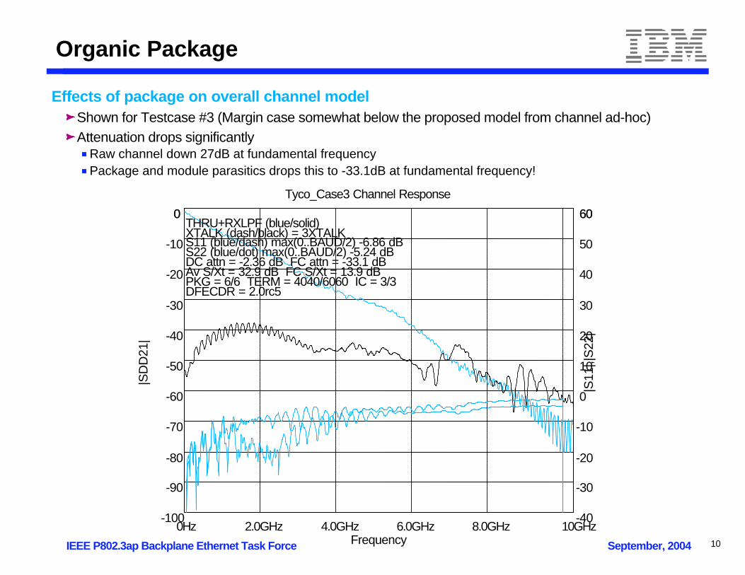
Organic Package
Effects of package on overall channel modelShown for Testcase #3 (Margin case somewhat below the proposed model from channel ad-hoc)Attenuation drops significantly
Raw channel down 27dB at fundamental frequencyPackage and module parasitics drops this to -33.1dB at fundamental frequency!
0Hz 10GHz2.0GHz 4.0GHz 6.0GHz 8.0GHz-100
0
-90
-80
-70
-60
-50
-40
-30
-20
-10
0
Tyco_Case3 Channel Response
Frequency
|SD
D21
|
-40
60
-30
-20
-10
0
10
20
30
40
50
60
|S11
|,|S
22|
THRU+RXLPF (blue/solid) XTALK (dash/black) = 3XTALK S11 (blue/dash) max(0..BAUD/2) -6.86 dB S22 (blue/dot) max(0..BAUD/2) -5.24 dB DC attn = -2.36 dB FC attn = -33.1 dB Av S/Xt = 32.9 dB FC S/Xt = 13.9 dB PKG = 6/6 TERM = 4040/6060 IC = 3/3 DFECDR = 2.0rc5
10
IEEE P802.3ap Backplane Ethernet Task Force September, 2004
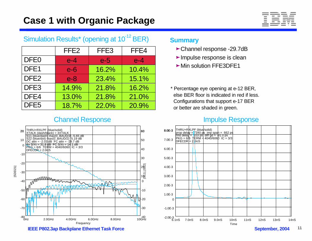
Case 1 with Organic Package
FFE2 FFE3 FFE4DFE0 e-4 e-5 e-4DFE1 e-6 16.2% 10.4%DFE2 e-8 23.4% 15.1%DFE3 14.9% 21.8% 16.2%DFE4 13.0% 21.8% 21.0%DFE5 18.7% 22.0% 20.9%
Simulation Results* (opening at 10-12 BER)
Channel Response Impulse Response
0Hz 10GHz2.0GHz 4.0GHz 6.0GHz 8.0GHz-80
20
-70
-60
-50
-40
-30
-20
-10
0
10
20
Frequency
|SD
D21
|
-40
60
-30
-20
-10
0
10
20
30
40
50
60
|S11
|,|S
22|
THRU+RXLPF (blue/solid) XTALK (dash/black) = 3XTALK S11 (blue/dash) max(0..BAUD/2) -5.65 dB S22 (blue/dot) max(0..BAUD/2) -5.19 dB DC attn = -2.03 dB FC attn = -29.7 dB Av S/Xt = 31.8 dB FC S/Xt = 14.1 dB PKG = 6/6 TERM = 4040/6060 IC = 3/3 DFECDR = 2.0rc5
6.1nS 14nS7.0nS 8.0nS 9.0nS 10nS 11nS 12nS 13nS-2.0E-3
8.0E-3
-1.0E-3
0
1.0E-3
2.0E-3
3.0E-3
4.0E-3
5.0E-3
6.0E-3
7.0E-3
8.0E-3
Time
THRU+RXLPF (blue/solid) prop delay = 7340 ps imp span = 662 ps rms delay = 103 ps diff gd = -91.0 ps PKG = 6/6 TERM = 4040/6060 IC = 3/3 DFECDR = 2.0rc5
SummaryChannel response -29.7dBImpulse response is cleanMin solution FFE3DFE1
* Percentage eye opening at e-12 BER, else BER floor is indicated in red if less. Configurations that support e-17 BER or better are shaded in green.
11
IEEE P802.3ap Backplane Ethernet Task Force September, 2004
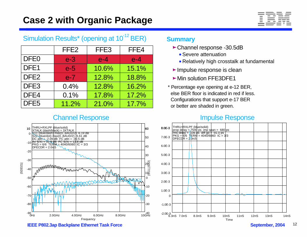
Case 2 with Organic Package
FFE2 FFE3 FFE4DFE0 e-3 e-4 e-4DFE1 e-5 10.6% 15.1%DFE2 e-7 12.8% 18.8%DFE3 0.4% 12.8% 16.2%DFE4 0.1% 17.8% 17.2%DFE5 11.2% 21.0% 17.7%
6.3nS 14nS7.0nS 8.0nS 9.0nS 10nS 11nS 12nS 13nS-2.0E-3
8.0E-3
-1.0E-3
0
1.0E-3
2.0E-3
3.0E-3
4.0E-3
5.0E-3
6.0E-3
7.0E-3
8.0E-3
Time
THRU+RXLPF (blue/solid) prop delay = 7540 ps imp span = 680 ps rms delay = 106 ps diff gd = -91.0 ps PKG = 6/6 TERM = 4040/6060 IC = 3/3 DFECDR = 2.0rc5
0Hz 10GHz2.0GHz 4.0GHz 6.0GHz 8.0GHz-90
10
-80
-70
-60
-50
-40
-30
-20
-10
0
10
Frequency
|SD
D21
|
-40
60
-30
-20
-10
0
10
20
30
40
50
60
|S11
|,|S
22|
THRU+RXLPF (blue/solid) XTALK (dash/black) = 3XTALK S11 (blue/dash) max(0..BAUD/2) -6.19 dB S22 (blue/dot) max(0..BAUD/2) -5.61 dB DC attn = -2.09 dB FC attn = -30.5 dB Av S/Xt = 31.9 dB FC S/Xt = 12.8 dB PKG = 6/6 TERM = 4040/6060 IC = 3/3 DFECDR = 2.0rc5
Channel Response Impulse Response
Simulation Results* (opening at 10-12 BER) SummaryChannel response -30.5dB
Severe attenuationRelatively high crosstalk at fundamental
Impulse response is cleanMin solution FFE3DFE1
* Percentage eye opening at e-12 BER, else BER floor is indicated in red if less. Configurations that support e-17 BER or better are shaded in green.
12
IEEE P802.3ap Backplane Ethernet Task Force September, 2004
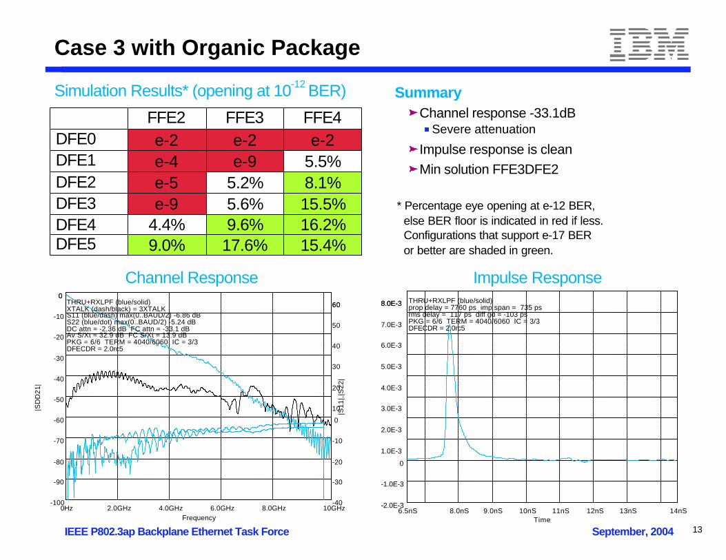
Case 3 with Organic Package
FFE2 FFE3 FFE4DFE0 e-2 e-2 e-2DFE1 e-4 e-9 5.5%DFE2 e-5 5.2% 8.1%DFE3 e-9 5.6% 15.5%DFE4 4.4% 9.6% 16.2%DFE5 9.0% 17.6% 15.4%
Channel Response Impulse Response
0Hz 10GHz2.0GHz 4.0GHz 6.0GHz 8.0GHz-100
0
-90
-80
-70
-60
-50
-40
-30
-20
-10
0
Frequency
|SD
D21
|
-40
60
-30
-20
-10
0
10
20
30
40
50
60
|S11
|,|S
22|
THRU+RXLPF (blue/solid) XTALK (dash/black) = 3XTALK S11 (blue/dash) max(0..BAUD/2) -6.86 dB S22 (blue/dot) max(0..BAUD/2) -5.24 dB DC attn = -2.36 dB FC attn = -33.1 dB Av S/Xt = 32.9 dB FC S/Xt = 13.9 dB PKG = 6/6 TERM = 4040/6060 IC = 3/3 DFECDR = 2.0rc5
6.5nS 14nS8.0nS 9.0nS 10nS 11nS 12nS 13nS-2.0E-3
8.0E-3
-1.0E-3
0
1.0E-3
2.0E-3
3.0E-3
4.0E-3
5.0E-3
6.0E-3
7.0E-3
8.0E-3
Time
THRU+RXLPF (blue/solid) prop delay = 7760 ps imp span = 735 ps rms delay = 117 ps diff gd = -103 ps PKG = 6/6 TERM = 4040/6060 IC = 3/3 DFECDR = 2.0rc5
Simulation Results* (opening at 10-12 BER) SummaryChannel response -33.1dB
Severe attenuation
Impulse response is cleanMin solution FFE3DFE2
* Percentage eye opening at e-12 BER, else BER floor is indicated in red if less. Configurations that support e-17 BER or better are shaded in green.
13
IEEE P802.3ap Backplane Ethernet Task Force September, 2004
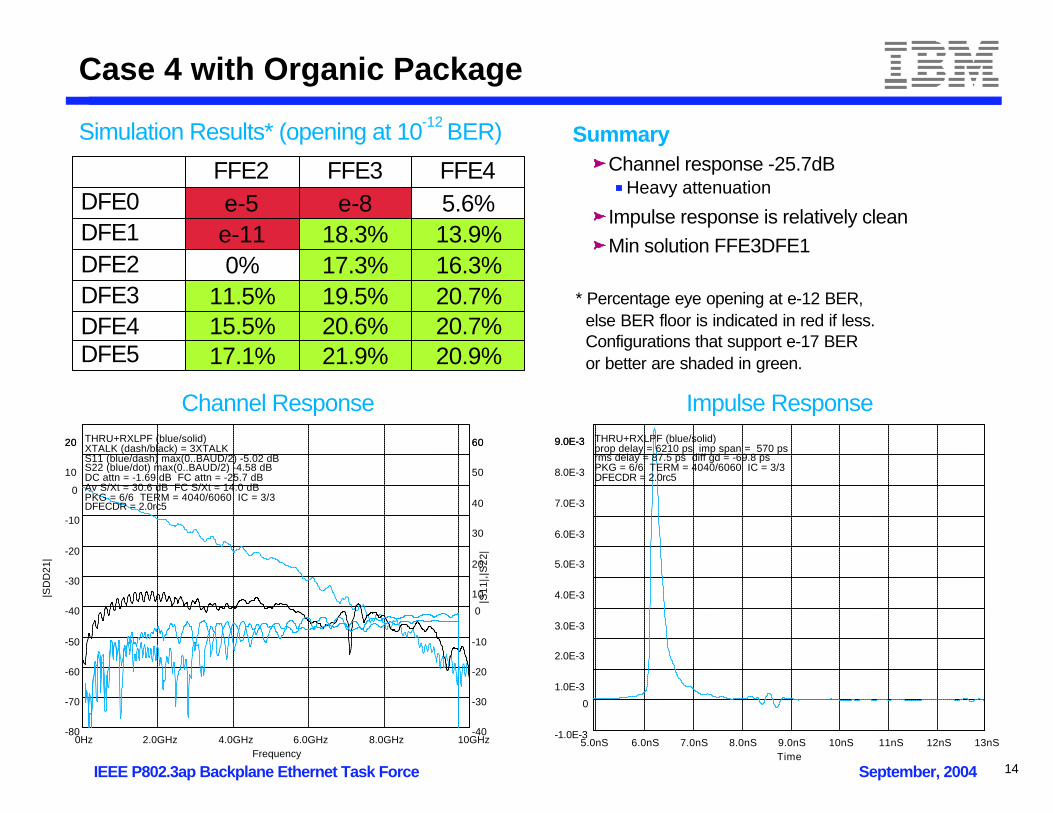
Case 4 with Organic Package
FFE2 FFE3 FFE4DFE0 e-5 e-8 5.6%DFE1 e-11 18.3% 13.9%DFE2 0% 17.3% 16.3%DFE3 11.5% 19.5% 20.7%DFE4 15.5% 20.6% 20.7%DFE5 17.1% 21.9% 20.9%
Channel Response Impulse Response
0Hz 10GHz2.0GHz 4.0GHz 6.0GHz 8.0GHz-80
20
-70
-60
-50
-40
-30
-20
-10
0
10
20
Frequency
|SD
D21
|
-40
60
-30
-20
-10
0
10
20
30
40
50
60
|S11
|,|S
22|
THRU+RXLPF (blue/solid) XTALK (dash/black) = 3XTALK S11 (blue/dash) max(0..BAUD/2) -5.02 dB S22 (blue/dot) max(0..BAUD/2) -4.58 dB DC attn = -1.69 dB FC attn = -25.7 dB Av S/Xt = 30.6 dB FC S/Xt = 14.0 dB PKG = 6/6 TERM = 4040/6060 IC = 3/3 DFECDR = 2.0rc5
5.0nS 13nS6.0nS 7.0nS 8.0nS 9.0nS 10nS 11nS 12nS-1.0E-3
9.0E-3
0
1.0E-3
2.0E-3
3.0E-3
4.0E-3
5.0E-3
6.0E-3
7.0E-3
8.0E-3
9.0E-3
Time
THRU+RXLPF (blue/solid) prop delay = 6210 ps imp span = 570 ps rms delay = 87.5 ps diff gd = -69.8 ps PKG = 6/6 TERM = 4040/6060 IC = 3/3 DFECDR = 2.0rc5
Simulation Results* (opening at 10-12 BER) SummaryChannel response -25.7dB
Heavy attenuation
Impulse response is relatively cleanMin solution FFE3DFE1
* Percentage eye opening at e-12 BER, else BER floor is indicated in red if less. Configurations that support e-17 BER or better are shaded in green.
14

IEEE P802.3ap Backplane Ethernet Task Force September, 2004
Case 5 with Organic Package
FFE2 FFE3 FFE4DFE0 5.7% 9.5% 20.2%DFE1 9.8% 21.1% 9.8%DFE2 12.2% 17.4% 9.7%DFE3 16.0% 18.9% 15.4%DFE4 18.8% 23.1% 12.2%DFE5 21.3% 22.2% 10.4%
Channel Response Impulse Response
0Hz 10GHz2.0GHz 4.0GHz 6.0GHz 8.0GHz-90
10
-80
-70
-60
-50
-40
-30
-20
-10
0
10
Frequency
|SD
D21
|
-40
60
-30
-20
-10
0
10
20
30
40
50
60
|S11
|,|S
22|
THRU+RXLPF (blue/solid) XTALK (dash/black) = 3XTALK S11 (blue/dash) max(0..BAUD/2) -4.59 dB S22 (blue/dot) max(0..BAUD/2) -4.06 dB DC attn = -1.13 dB FC attn = -20.4 dB Av S/Xt = 29.9 dB FC S/Xt = 16.5 dB PKG = 6/6 TERM = 4040/6060 IC = 3/3 DFECDR = 2.0rc5
3.2nS 11nS4.0nS 5.0nS 6.0nS 7.0nS 8.0nS 9.0nS 10nS-4.0E-3
16E-3
-2.0E-3
0
2.0E-3
4.0E-3
6.0E-3
8.0E-3
10E-3
12E-3
14E-3
16E-3
Time
THRU+RXLPF (blue/solid) prop delay = 4480 ps imp span = 463 ps rms delay = 67.0 ps diff gd = -48.5 ps PKG = 6/6 TERM = 4040/6060 IC = 3/3 DFECDR = 2.0rc5
Simulation Results* (opening at 10-12 BER) SummaryChannel response -20.4dB
Relatively high ave crosstalk
Impulse response is relatively cleanMin solution FFE3
No DFE required
* Percentage eye opening at e-12 BER, else BER floor is indicated in red if less. Configurations that support e-17 BER or better are shaded in green.
15
IEEE P802.3ap Backplane Ethernet Task Force September, 2004
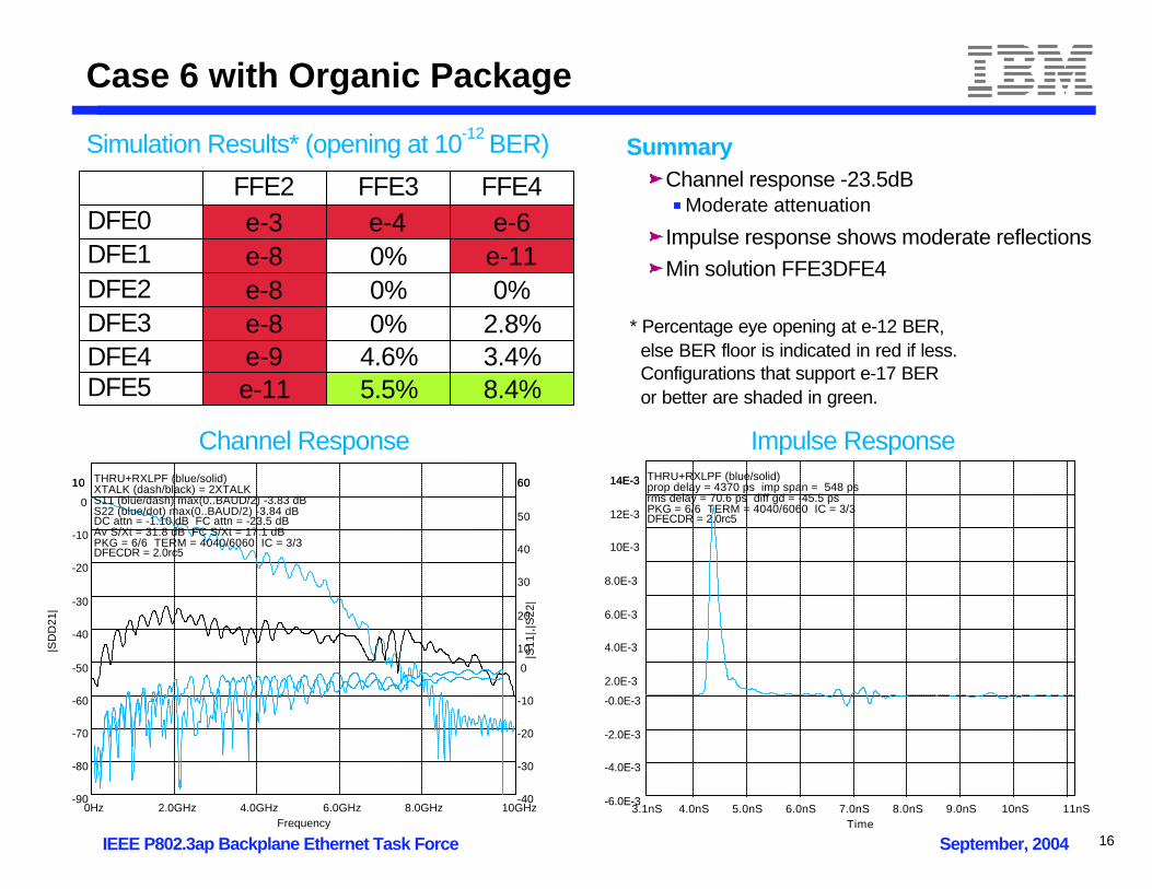
Case 6 with Organic Package
FFE2 FFE3 FFE4DFE0 e-3 e-4 e-6DFE1 e-8 0% e-11DFE2 e-8 0% 0%DFE3 e-8 0% 2.8%DFE4 e-9 4.6% 3.4%DFE5 e-11 5.5% 8.4%
Channel Response Impulse Response
0Hz 10GHz2.0GHz 4.0GHz 6.0GHz 8.0GHz-90
10
-80
-70
-60
-50
-40
-30
-20
-10
0
10
Frequency
|SD
D21
|
-40
60
-30
-20
-10
0
10
20
30
40
50
60
|S11
|,|S
22|
THRU+RXLPF (blue/solid) XTALK (dash/black) = 2XTALK S11 (blue/dash) max(0..BAUD/2) -3.83 dB S22 (blue/dot) max(0..BAUD/2) -3.84 dB DC attn = -1.10 dB FC attn = -23.5 dB Av S/Xt = 31.8 dB FC S/Xt = 17.1 dB PKG = 6/6 TERM = 4040/6060 IC = 3/3 DFECDR = 2.0rc5
3.1nS 11nS4.0nS 5.0nS 6.0nS 7.0nS 8.0nS 9.0nS 10nS-6.0E-3
14E-3
-4.0E-3
-2.0E-3
-0.0E-3
2.0E-3
4.0E-3
6.0E-3
8.0E-3
10E-3
12E-3
14E-3
Time
THRU+RXLPF (blue/solid) prop delay = 4370 ps imp span = 548 ps rms delay = 70.6 ps diff gd = -45.5 ps PKG = 6/6 TERM = 4040/6060 IC = 3/3 DFECDR = 2.0rc5
Simulation Results* (opening at 10-12 BER) SummaryChannel response -23.5dB
Moderate attenuation
Impulse response shows moderate reflectionsMin solution FFE3DFE4
* Percentage eye opening at e-12 BER, else BER floor is indicated in red if less. Configurations that support e-17 BER or better are shaded in green.
16

IEEE P802.3ap Backplane Ethernet Task Force September, 2004
Case 7 with Organic Package
FFE2 FFE3 FFE4DFE0 e-5 e-5 e-6DFE1 e-9 0.1% 0%DFE2 e-11 4.6% 3.8%DFE3 0.1% 4.4% 4.8%DFE4 6.2% 6.2% 12.1%DFE5 10.9% 9.7% 9.7%
Channel Response Impulse Response
0Hz 10GHz2.0GHz 4.0GHz 6.0GHz 8.0GHz-90
10
-80
-70
-60
-50
-40
-30
-20
-10
0
10
Frequency
|SD
D21
|
-40
60
-30
-20
-10
0
10
20
30
40
50
60
|S11
|,|S
22|
THRU+RXLPF (blue/solid) XTALK (dash/black) = 3XTALK S11 (blue/dash) max(0..BAUD/2) -4.32 dB S22 (blue/dot) max(0..BAUD/2) -3.45 dB DC attn = -0.71 dB FC attn = -19.7 dB Av S/Xt = 30.2 dB FC S/Xt = 15.2 dB PKG = 6/6 TERM = 4040/6060 IC = 3/3 DFECDR = 2.0rc5
1.8nS 8.5nS3.0nS 4.0nS 5.0nS 6.0nS 7.0nS-4.0E-3
16E-3
-2.0E-3
0
2.0E-3
4.0E-3
6.0E-3
8.0E-3
10E-3
12E-3
14E-3
16E-3
Time
THRU+RXLPF (blue/solid) prop delay = 3050 ps imp span = 558 ps rms delay = 59.9 ps diff gd = -36.4 ps PKG = 6/6 TERM = 4040/6060 IC = 3/3 DFECDR = 2.0rc5
Simulation Results* (opening at 10-12 BER) SummaryChannel response -19.7dB
Relatively low attenuation
Impulse response shows multiple reflectionsMin solution FFE3DFE1
* Percentage eye opening at e-12 BER, else BER floor is indicated in red if less. Configurations that support e-17 BER or better are shaded in green.
17

IEEE P802.3ap Backplane Ethernet Task Force September, 2004
Flip Chip Plastic Package
Effects of package on overall channel modelShown for Testcase #3 (Margin case somewhat below the proposed model from channel ad-hoc)Attenuation drops significantly
Raw channel down 27dB at fundamental fequencyPackage and module parasitics drops this to -35.3 dB at fundamental frequency!
0Hz 10GHz2.0GHz 4.0GHz 6.0GHz 8.0GHz-100
0
-90
-80
-70
-60
-50
-40
-30
-20
-10
0
Tyco_Case3 Channel Response
Frequency
|SD
D21
|
-40
60
-30
-20
-10
0
10
20
30
40
50
60
|S11
|,|S
22|
THRU+RXLPF (blue/solid) XTALK (dash/black) = 3XTALK S11 (blue/dash) max(0..BAUD/2) -7.38 dB S22 (blue/dot) max(0..BAUD/2) -4.21 dB DC attn = -2.37 dB FC attn = -35.3 dB Av S/Xt = 33.1 dB FC S/Xt = 13.9 dB PKG = 8/8 TERM = 4040/6060 IC = 3/3 DFECDR = 2.0rc5
18

IEEE P802.3ap Backplane Ethernet Task Force September, 2004
Case 1 with Plastic Package
FFE2 FFE3 FFE4DFE0 e-2 e-4 e-3DFE1 e-5 10.8% 10.9%DFE2 e-6 14.7% 13.8%DFE3 e-10 14.7% 16.6%DFE4 5.0% 16.0% 16.1%DFE5 5.7% 16.7% 20.4%
Simulation Results* (opening at 10-12 BER)
Channel Response Impulse Response
SummaryChannel response -32.8dBImpulse response is cleanMin solution FFE3DFE1
* Percentage eye opening at e-12 BER, else BER floor is indicated in red if less. Configurations that support e-17 BER or better are shaded in green.
0Hz 10GHz2.0GHz 4.0GHz 6.0GHz 8.0GHz-90
10
-80
-70
-60
-50
-40
-30
-20
-10
0
10
Frequency
|SD
D21
|
-40
60
-30
-20
-10
0
10
20
30
40
50
60
|S11
|,|S
22|
THRU+RXLPF (blue/solid) XTALK (dash/black) = 3XTALK S11 (blue/dash) max(0..BAUD/2) -5.96 dB S22 (blue/dot) max(0..BAUD/2) -4.00 dB DC attn = -2.01 dB FC attn = -32.8 dB Av S/Xt = 32.1 dB FC S/Xt = 14.1 dB PKG = 8/8 TERM = 4040/6060 IC = 3/3 DFECDR = 2.0rc5
6.1nS 14nS7.0nS 8.0nS 9.0nS 10nS 11nS 12nS 13nS-2.0E-3
8.0E-3
-1.0E-3
0
1.0E-3
2.0E-3
3.0E-3
4.0E-3
5.0E-3
6.0E-3
7.0E-3
8.0E-3
Time
THRU+RXLPF (blue/solid) prop delay = 7350 ps imp span = 667 ps rms delay = 103 ps diff gd = -85.0 ps PKG = 8/8 TERM = 4040/6060 IC = 3/3 DFECDR = 2.0rc5
19

IEEE P802.3ap Backplane Ethernet Task Force September, 2004
Case 2 with Plastic Package
FFE2 FFE3 FFE4DFE0 e-2 e-3 e-3DFE1 e-4 4.8% 11.6%DFE2 e-5 8.3% 10.9%DFE3 e-8 5.2% 16.6%DFE4 0.1% 15.1% 16.0%DFE5 4.3% 17.3% 15.5%
Simulation Results* (opening at 10-12 BER)
Channel Response Impulse Response
* Percentage eye opening at e-12 BER, else BER floor is indicated in red if less. Configurations that support e-17 BER or better are shaded in green.
0Hz 10GHz2.0GHz 4.0GHz 6.0GHz 8.0GHz-90
10
-80
-70
-60
-50
-40
-30
-20
-10
0
10
Frequency
|SD
D21
|
-40
60
-30
-20
-10
0
10
20
30
40
50
60
|S11
|,|S
22|
THRU+RXLPF (blue/solid) XTALK (dash/black) = 3XTALK S11 (blue/dash) max(0..BAUD/2) -6.55 dB S22 (blue/dot) max(0..BAUD/2) -3.75 dB DC attn = -2.08 dB FC attn = -33.3 dB Av S/Xt = 32.1 dB FC S/Xt = 12.7 dB PKG = 8/8 TERM = 4040/6060 IC = 3/3 DFECDR = 2.0rc5
6.3nS 14nS7.0nS 8.0nS 9.0nS 10nS 11nS 12nS 13nS-2.0E-3
8.0E-3
-1.0E-3
0
1.0E-3
2.0E-3
3.0E-3
4.0E-3
5.0E-3
6.0E-3
7.0E-3
8.0E-3
Time
THRU+RXLPF (blue/solid) prop delay = 7550 ps imp span = 681 ps rms delay = 107 ps diff gd = -85.0 ps PKG = 8/8 TERM = 4040/6060 IC = 3/3 DFECDR = 2.0rc5
SummaryChannel response -33.3dB
Severe attenuationRelatively high crosstalk at fundamental
Impulse response is cleanMin solution FFE3DFE1
20

IEEE P802.3ap Backplane Ethernet Task Force September, 2004
Case 3 with Plastic Package
FFE2 FFE3 FFE4DFE0 e-2 e-2 e-2DFE1 e-3 e-8 7.0%DFE2 e-3 0% 10.9%DFE3 e-7 0.1% 13.5%DFE4 e-9 11.0% 12.1%DFE5 0.1% 14.3% 14.5%
Simulation Results* (opening at 10-12 BER)
Channel Response Impulse Response
* Percentage eye opening at e-12 BER, else BER floor is indicated in red if less. Configurations that support e-17 BER or better are shaded in green.
0Hz 10GHz2.0GHz 4.0GHz 6.0GHz 8.0GHz-100
0
-90
-80
-70
-60
-50
-40
-30
-20
-10
0
Frequency
|SD
D21
|
-40
60
-30
-20
-10
0
10
20
30
40
50
60
|S11
|,|S
22|
THRU+RXLPF (blue/solid) XTALK (dash/black) = 3XTALK S11 (blue/dash) max(0..BAUD/2) -7.38 dB S22 (blue/dot) max(0..BAUD/2) -4.21 dB DC attn = -2.37 dB FC attn = -35.3 dB Av S/Xt = 33.1 dB FC S/Xt = 13.9 dB PKG = 8/8 TERM = 4040/6060 IC = 3/3 DFECDR = 2.0rc5
6.5nS 15nS8.0nS 9.0nS 10nS 11nS 12nS 13nS 14nS-2.0E-3
8.0E-3
-1.0E-3
0
1.0E-3
2.0E-3
3.0E-3
4.0E-3
5.0E-3
6.0E-3
7.0E-3
8.0E-3
Time
THRU+RXLPF (blue/solid) prop delay = 7770 ps imp span = 741 ps rms delay = 118 ps diff gd = -100 ps PKG = 8/8 TERM = 4040/6060 IC = 3/3 DFECDR = 2.0rc5
SummaryChannel response -35.3dB
Severe attenuation
Impulse response is cleanMin solution FFE3DFE3
21

IEEE P802.3ap Backplane Ethernet Task Force September, 2004
Case 4 with Plastic Package
FFE2 FFE3 FFE4DFE0 e-4 e-5 e-6DFE1 e-7 18.8% 18.5%DFE2 e-8 16.6% 16.4%DFE3 11.1% 20.4% 16.6%DFE4 20.7% 23.2% 18.0%DFE5 17.3% 23.5% 21.0%
Simulation Results* (opening at 10-12 BER)
Channel Response Impulse Response
* Percentage eye opening at e-12 BER, else BER floor is indicated in red if less. Configurations that support e-17 BER or better are shaded in green.
0Hz 10GHz2.0GHz 4.0GHz 6.0GHz 8.0GHz-80
20
-70
-60
-50
-40
-30
-20
-10
0
10
20
Frequency
|SD
D21
|
-40
60
-30
-20
-10
0
10
20
30
40
50
60
|S11
|,|S
22|
THRU+RXLPF (blue/solid) XTALK (dash/black) = 3XTALK S11 (blue/dash) max(0..BAUD/2) -5.02 dB S22 (blue/dot) max(0..BAUD/2) -3.94 dB DC attn = -1.76 dB FC attn = -28.3 dB Av S/Xt = 30.9 dB FC S/Xt = 14.2 dB PKG = 8/8 TERM = 4040/6060 IC = 3/3 DFECDR = 2.0rc5
5.0nS 13nS6.0nS 7.0nS 8.0nS 9.0nS 10nS 11nS 12nS-1.0E-3
9.0E-3
0
1.0E-3
2.0E-3
3.0E-3
4.0E-3
5.0E-3
6.0E-3
7.0E-3
8.0E-3
9.0E-3
Time
THRU+RXLPF (blue/solid) prop delay = 6250 ps imp span = 609 ps rms delay = 92.5 ps diff gd = -78.9 ps PKG = 8/8 TERM = 4040/6060 IC = 3/3 DFECDR = 2.0rc5
SummaryChannel response -28.3dB
Heavy attenuation
Impulse response is relatively cleanMin solution FFE3DFE1
22
IEEE P802.3ap Backplane Ethernet Task Force September, 2004
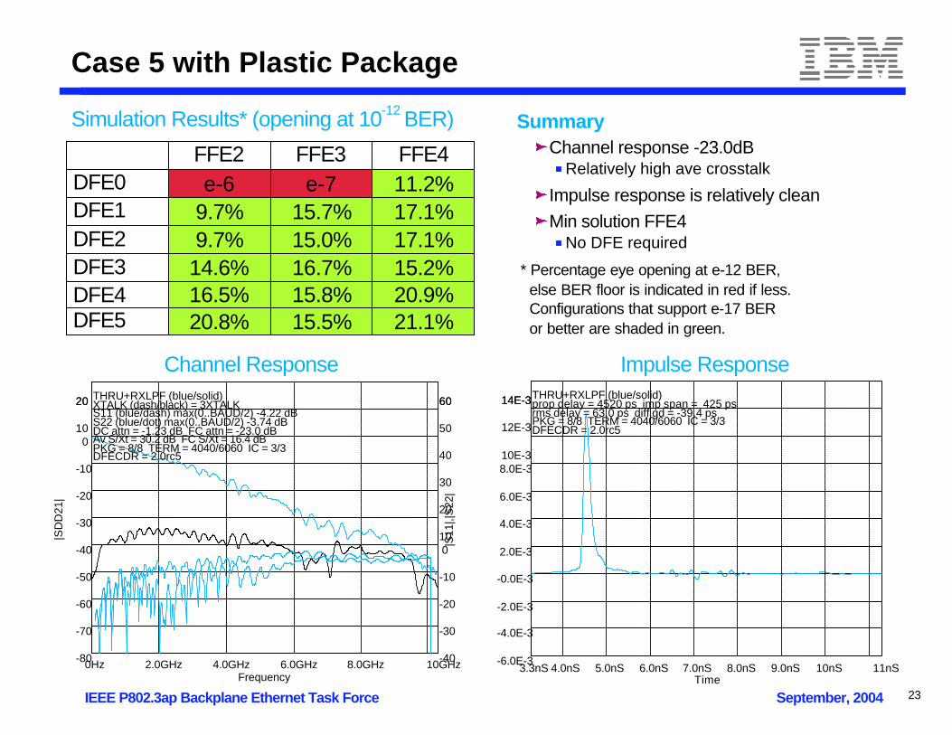
Case 5 with Plastic Package
FFE2 FFE3 FFE4DFE0 e-6 e-7 11.2%DFE1 9.7% 15.7% 17.1%DFE2 9.7% 15.0% 17.1%DFE3 14.6% 16.7% 15.2%DFE4 16.5% 15.8% 20.9%DFE5 20.8% 15.5% 21.1%
Simulation Results* (opening at 10-12 BER)
Channel Response Impulse Response
* Percentage eye opening at e-12 BER, else BER floor is indicated in red if less. Configurations that support e-17 BER or better are shaded in green.
0Hz 10GHz2.0GHz 4.0GHz 6.0GHz 8.0GHz-80
20
-70
-60
-50
-40
-30
-20
-10
0
10
20
Frequency
|SD
D21
|
-40
60
-30
-20
-10
0
10
20
30
40
50
60
|S11
|,|S
22|
THRU+RXLPF (blue/solid) XTALK (dash/black) = 3XTALK S11 (blue/dash) max(0..BAUD/2) -4.22 dB S22 (blue/dot) max(0..BAUD/2) -3.74 dB DC attn = -1.23 dB FC attn = -23.0 dB Av S/Xt = 30.2 dB FC S/Xt = 16.4 dB PKG = 8/8 TERM = 4040/6060 IC = 3/3 DFECDR = 2.0rc5
3.3nS 11nS4.0nS 5.0nS 6.0nS 7.0nS 8.0nS 9.0nS 10nS-6.0E-3
14E-3
-4.0E-3
-2.0E-3
-0.0E-3
2.0E-3
4.0E-3
6.0E-3
8.0E-3
10E-3
12E-3
14E-3
Time
THRU+RXLPF (blue/solid) prop delay = 4520 ps imp span = 425 ps rms delay = 63.0 ps diff gd = -39.4 ps PKG = 8/8 TERM = 4040/6060 IC = 3/3 DFECDR = 2.0rc5
SummaryChannel response -23.0dB
Relatively high ave crosstalk
Impulse response is relatively cleanMin solution FFE4
No DFE required
23

IEEE P802.3ap Backplane Ethernet Task Force September, 2004
Case 6 with Plastic Package
FFE2 FFE3 FFE4DFE0 e-3 e-3 e-4DFE1 e-7 0% e-9DFE2 e-8 0% e-11DFE3 e-8 4.1% 0.1%DFE4 e-10 4.4% 0%DFE5 0% 4.6% 3.9%
Simulation Results* (opening at 10-12 BER)
Channel Response Impulse Response
* Percentage eye opening at e-12 BER, else BER floor is indicated in red if less. Configurations that support e-17 BER or better are shaded in green.
0Hz 10GHz2.0GHz 4.0GHz 6.0GHz 8.0GHz-90
10
-80
-70
-60
-50
-40
-30
-20
-10
0
10
Frequency
|SD
D21
|
-40
60
-30
-20
-10
0
10
20
30
40
50
60
|S11
|,|S
22|
THRU+RXLPF (blue/solid) XTALK (dash/black) = 2XTALK S11 (blue/dash) max(0..BAUD/2) -3.57 dB S22 (blue/dot) max(0..BAUD/2) -3.01 dB DC attn = -1.20 dB FC attn = -25.9 dB Av S/Xt = 32.0 dB FC S/Xt = 17.2 dB PKG = 8/8 TERM = 4040/6060 IC = 3/3 DFECDR = 2.0rc5
3.2nS 11nS4.0nS 5.0nS 6.0nS 7.0nS 8.0nS 9.0nS 10nS-6.0E-3
14E-3
-4.0E-3
-2.0E-3
-0.0E-3
2.0E-3
4.0E-3
6.0E-3
8.0E-3
10E-3
12E-3
14E-3
Time
THRU+RXLPF (blue/solid) prop delay = 4410 ps imp span = 479 ps rms delay = 65.6 ps diff gd = -36.4 ps PKG = 8/8 TERM = 4040/6060 IC = 3/3 DFECDR = 2.0rc5
SummaryChannel response -25.9dB
Moderate attenuation
Impulse response shows moderate reflectionsMin solution FFE3DFE3
24

IEEE P802.3ap Backplane Ethernet Task Force September, 2004
Case 7 with Plastic Package
FFE2 FFE3 FFE4DFE0 e-4 e-4 e-5DFE1 e-11 e-9 0.4%DFE2 e-9 0.4% 5.4%DFE3 4.1% 1.7% 3.9%DFE4 1.5% 4.7% 5.8%DFE5 5.9% 3.8% 4.2%
Simulation Results* (opening at 10-12 BER)
Channel Response Impulse Response
* Percentage eye opening at e-12 BER, else BER floor is indicated in red if less. Configurations that support e-17 BER or better are shaded in green.
0Hz 10GHz2.0GHz 4.0GHz 6.0GHz 8.0GHz-90
10
-80
-70
-60
-50
-40
-30
-20
-10
0
10
Frequency
|SD
D21
|
-40
60
-30
-20
-10
0
10
20
30
40
50
60
|S11
|,|S
22|
THRU+RXLPF (blue/solid) XTALK (dash/black) = 3XTALK S11 (blue/dash) max(0..BAUD/2) -4.77 dB S22 (blue/dot) max(0..BAUD/2) -3.07 dB DC attn = -0.70 dB FC attn = -22.7 dB Av S/Xt = 30.6 dB FC S/Xt = 15.1 dB PKG = 8/8 TERM = 4040/6060 IC = 3/3 DFECDR = 2.0rc5
1.8nS 8.5nS3.0nS 4.0nS 5.0nS 6.0nS 7.0nS-4.0E-3
16E-3
-2.0E-3
0
2.0E-3
4.0E-3
6.0E-3
8.0E-3
10E-3
12E-3
14E-3
16E-3
Time
THRU+RXLPF (blue/solid) prop delay = 3010 ps imp span = 415 ps rms delay = 57.4 ps diff gd = -33.4 ps PKG = 8/8 TERM = 4040/6060 IC = 3/3 DFECDR = 2.0rc5
SummaryChannel response -22.7dB
Relatively low attenuation
Impulse response shows multiple reflectionsMin solution FFE3DFE2
25

IEEE P802.3ap Backplane Ethernet Task Force September, 2004
Summary
NO, We Don't Need 10+ Tap DFEs!All channels shown to be solvable with nominal DFE designs - summary of minimum configurations:
Significant room exists for vendors to add robustnesse.g. 4-tap FFE, 5-tap DFE
Room exists for vendors to optimize for powere.g. 3-tap FFE, 1-tap DFE solved channels above proposed ad-hoc linee.g. Duobinary receiver with common NRZ 3-tap FFE transmitter
Feasibility shown with a proven simulator, with full modeling of serdes & channelThoroughly correlated to hardware characterized across process, voltage, & temperature
Evaluation conservatively performed for worst case conditionsWorst case DJ, RJ, Termination tolerance, etc as expected to be defined by standardConservative 10G parasitic extraction estimates
NRZ/DFE architecture validated in existing designsSignificant experience with 6.25Gbps FFE4/DFE5 hardwareOperates across channels of comparable and even worse quality than those proposed to signaling ad-hoc
Case1 Case2 Case3 Case4 Case5 Case6 Case7Organic FFE3DFE1 FFE3DFE1 FFE3DFE2 FFE3DFE1 FFE3 FFE3DFE4 FFE3DFE1Plastic FFE3DFE1 FFE3DFE1 FFE3DFE2 FFE3DFE1 FFE4 FFE3DFE3 FFE3DFE2
26