presented by elizabeth burton lawrence berkeley … library/events/2012/carbon storage...
TRANSCRIPT
Project Number:
DE-FC26-05NT42593
Presented by Elizabeth Burton
Lawrence Berkeley National Laboratory
On behalf of Mike Gravely, WESTCARB P.I.,
California Energy Commission
U.S. Department of Energy
National Energy Technology Laboratory
Carbon Storage R&D Project Review Meeting
Developing the Technologies and Building the
Infrastructure for CO2 Storage
August 21-23, 2012

2
Presentation Outline
• Project Overview—Goals
• Technical Status/Accomplishments
– Northern California characterization well
– CCUS-NGCC engineering-economic study
– Policy/Regulatory outreach
• Highlights of Future Plans

3
Project Overview: WESTCARB Goals and Objectives Align with RCSP
Program Goals WESTCARB Goals and Objectives
(Budget Period 3 -- through 2013)
Characterize geologic
sequestration potential and
capacity in WESTCARB region
based on geology and
geographic criteria
Identify and define promising
sites and facilitate the process
for developing commercial-scale
CCUS projects
Identify regulatory/economic
impediments to project
development, potential solutions
to impediments, and
methodologies to incorporate
CCUS as accepted technology
for (GHG) emissions reduction.
RCSP Goals
Develop technologies
that will support
industries’ ability to
predict CO2 storage
capacity in geologic
formations to within ±30
percent.
Conduct field tests
through 2030 to support
the development of
BPMs for site selection,
characterization, site
operations, and closure
practices.
Success Criteria
Reports to WESTCARB
website and portal
Data layers for states into
NATCARB
High potential sites
identified, characterization
seismic or wells
permitted, drilled,
completed, closed;
engineering/economic
assessments completed
Workshops, testimony,
reports to assist
policymakers and
regulators
Drill site
Central Valley
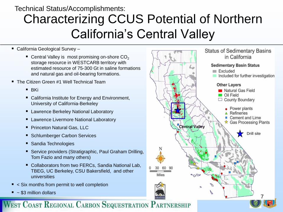
California Geological Survey –
Central Valley is most promising on-shore CO2
storage resource in WESTCARB territory with
estimated resource of 75-300 Gt in saline formations
and natural gas and oil-bearing formations.
The Citizen Green #1 Well Technical Team
BKi
California Institute for Energy and Environment,
University of California-Berkeley
Lawrence Berkeley National Laboratory
Lawrence Livermore National Laboratory
Princeton Natural Gas, LLC
Schlumberger Carbon Services
Sandia Technologies
Service providers (Stratigraphic, Paul Graham Drilling,
Tom Fazio and many others)
Collaborators from two FERCs, Sandia National Lab,
TBEG, UC Berkeley, CSU Bakersfield, and other
universities
< Six months from permit to well completion
~ $3 million dollars
Characterizing CCUS Potential of Northern
California’s Central Valley
7
Technical Status/Accomplishments:

Objectives of the
Citizen Green well
• Assess storage capacity of major
regional sandstone formations
• Assess seal integrity of major
regional shale units
• Integrate lab and field data to
understand regional resource
– Geochemical and petrophysical
lab testing and analysis of core
and fluid samples
– Well logs and seismic
– Outcrop and log data from nearby
locations
– Simulations of commercial-scale
injection, multiphase flow and
trapping mechanisms
5
Technical Status/Accomplishments:

Nortonville Shale
Capay Shale
Nortonville Sand
Domengine
Fm.
(sand)
Mokelumne
River Fm.
(sand)
H&T Shale
Gas Accumulation
SP
Top Starkey Sand
Starkey Shale
Permeability Porosity Sonic Vp/Vs
Citizen Green #1 Well drilled to 6,920 ft TVD
intersected 3 target sandstones and 4 shale units
Technical Status/Accomplishments:

Sidewall #24
5782 ft TVD
Lower Mokelumne
Porosity 33%
Air Perm. 367 mD
Sidewall #14
6315 ft TVD
H&T Shale
Porosity 22%
Air Perm. < 5 mD
Sidewall #8
6496 ft TVD
Top Starkey Sand
Porosity 31%
Air Perm. 432 mD
Thin Section, 10x Surface Texture, 1x
Confirms Lower
Mokelumne
as injection target
Confirms
Top Starkey
as injection target
Top Starkey
Sand
H&T Shale
Mokelumne
River Fm.
(sand)
Starkey Shale
Technical Status/Accomplishments:
Petrophysics from Sidewall Core Analysis

Characteristics of Storage and Sealing
Formations, Citizen Green Well #1
Domengine – High permeabilities (3+ Darcies) observed on
Combinable Magnetic Resonance (CMR) log. Unconsolidated
sandstone, over 500 ft thick. Overlying Nortonville shale questionable
seal--may impair regional storage utility of Dom.
Mokelumne River – High permeabilities (1+ Darcy from CMR in
upper section of unconsolidated sand. Thickness 1500 ft (460 m).
Tighter with depth; consolidated below 5500 ft (1676 m). Capay Shale
provides good seal, supported by natural gas common in Moke
regionally
Top Starkey Sandstone – Moderate to low permeabilities (≤100 mD
from CMR) Consolidated sand with shaly stringers; several sand
lobes with higher permeability. H&T Shale provides good seal
Technical Status/Accomplishments:

Petrophysical Analysis: Seismic Data from scCO2
Injection in Brine-Saturated Core
Sample: Domengine sandstone core
6" long, 1.5" diameter, from Black Diamond Mine
>2-3 Darcy permeability, ~30% porosity
Test conditions to mimic in-situ conditions at top of high
perm section of Domengine:
Confining pressure = 4,000 psi, pore pressure =
2,000 psi,
Temperature = 56.6oC,
1% NaCl (10,000 mg/l) brine solution
Flow scCO2 into brine-saturated core until breakthrough,
followed by flowing CO2-free brine
Sample in Split Hopkinson Resonance Bar
apparatus for seismic experiment
Seismic velocities (Vp and Vs) Seismic velocity attenuation Effluent brine pH
Technical Status/Accomplishments:
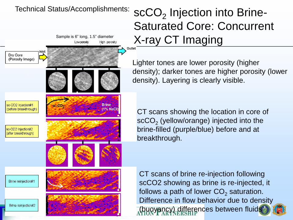
Sample is 6” long, 1.5” diameter
scCO2 Injection into Brine-
Saturated Core: Concurrent
X-ray CT Imaging
Lighter tones are lower porosity (higher
density); darker tones are higher porosity (lower
density). Layering is clearly visible.
CT scans showing the location in core of
scCO2 (yellow/orange) injected into the
brine-filled (purple/blue) before and at
breakthrough.
CT scans of brine re-injection following
scCO2 showing as brine is re-injected, it
follows a path of lower CO2 saturation.
Difference in flow behavior due to density
(buoyancy) differences between fluids
Technical Status/Accomplishments:
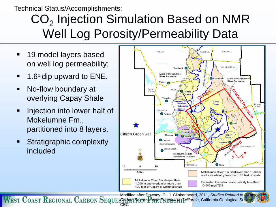
Citizen Green well
x y
Modified after Downey, C., J. Clinkenbeard, 2011, Studies Related to Geologic
Carbon Sequestration Potential in California, California Geological Survey,
CEC
CO2 Injection Simulation Based on NMR
Well Log Porosity/Permeability Data
19 model layers based
on well log permeability;
1.6o dip upward to ENE.
No-flow boundary at
overlying Capay Shale
Injection into lower half of
Mokelumne Fm.,
partitioned into 8 layers.
Stratigraphic complexity
included
Technical Status/Accomplishments:

Stratigraphic and structural complexity
affects capacity estimates
• Erosional gorge
downcuts Mokelumne
surrounding pinnacle
at site
• Overlying and
underlying formations
are stratigraphically
continuous
• Pervasive faulting
– Has created gas traps
– Spill points unknown
12
From May, J, et al, Amplitude anomalies in a sequence stratigrphic framework: Exploration
successes and pitfalls in a subgorge play, Sacramento Basin, California. SEG Bulletin.
Technical Status/Accomplishments:

Simulated CO2 Injection Results to Date
Strong lateral flow within
high-permeability layers;
slight up-dip migration
Strong vertical buoyancy
flow within high-permeability
layers
Low permeability baffles
greatly reduce effective
vertical permeability
4 Mt CO2 plume diameter
~3900 ft (1200 m), height
1150 ft (350 m), still 360 ft
(110 m) below top of
reservoir
250,000 kt CO2 injected over 3 months
4 Mt CO2 injected over 4 years
Technical Status/Accomplishments:

14
www.westcarb.org

Engineering-Economic Assessment of CCUS for
Natural Gas Combined Cycle Power Plants
• Technical Team
– Bki
– Lawrence Livermore National Lab
– Shaw Group
– Industry Partners (PG&E, SoCal Gas,
SCE, SMUD, Clean Energy Systems)
– Visage Energy
• ~50% of state’s electricity generated
with natural gas from young plants
that operate at high capacity factors.
• Many plants located above or near
potential CO2 resource, including oil
fields suitable for CO2-EOR.
15
Technical Status/Accomplishments:

Interim Findings: Capture & Compression
• For retrofit NGCC plants with dry cooling,
conventional post-combustion capture leads to cost
and energy penalties for solvent and compressor
cooling.
– Potential design solution saves >60MW: Relax
solvent CO2 absorber inlet temperature design point;
Accept more hot days on which solvent cannot be
cooled to design temperature
– Potential technical solution: Find solvents effective at
higher operating temperatures (without undue
regeneration heating requirements)
• CCS more cost effective by about 30% ($16/MWh)
for “new build” than retrofit because:
– CCS integrated into plant design optimizes thermal
integration of capture plant and base plant processes
– Equipment design selected to better accommodate
capture operation, and optimize plant layout
16
Technical Status/Accomplishments:

Interim Findings: Economics
• Sensitivity studies identified 4 main factors
on CCS economics:
– capacity factor
– capital cost
– price on CO2
– discount rate.
• Plugging the higher variable O&M cost of
an NGCC-CCS plant into a conventional
grid dispatch model will lead to
unacceptably low dispatch (capacity factor)
– Potential solution: Regulatory or ISO
support for early commercial projects, such
as a “must run” designation or a “loading
order” priority.
17
Technical Status/Accomplishments:
Interim Findings: Storage and
Transportation Costs
• There are trade-offs between well field site selection and pipeline
costs.
– Pipeline costs increase with urbanization (siting sensitivities,
number of crossings of other infrastrucuture)
– Pipeline costs depend on distance and capacity
– Well field costs (well length, number of wells) vary with site
characteristics (depth of storage fm, capacity and injectivity per
well, drilling difficulty).
– Well field costs tend to increase faster than pipeline costs as
project size grows.
18
Technical Status/Accomplishments:
Policy/Regulatory Outreach
• California CCS Review Panel
• Seismic Hazards in West Coast Region
• California Senate Bill 1139
• USEA Workshop for Policymakers
19
Technical Status/Accomplishments:
WESTCARB ANNUAL MEETING
week of October 15, 2012
in beautiful Bakersfield, CA
Highlights of Future Plans
1. Characterization of high potential sites in Arizona
2. “Virtual Petrophysics” and other ways to reduce characterization
costs/risks
3. Cross-cutting issues for site selection : tools for demographic issues,
seismic, competing subsurface activities
4. Integration and issues for CCUS in future energy planning scenarios
5. Exploring pilot or demonstration project options with industry
partners

Acknowledgments, Disclaimers
• Acknowledgments: – This material is based upon work supported by the U.S. Department of Energy (DOE) National Energy
Technology Laboratory (NETL) under Grant Number DE-FC26-05NT42593. This project is managed and
administered by the California Energy Commission and funded by DOE/NETL and cost-sharing partners.
• Disclaimers: – “This report was prepared as an account of work sponsored by an agency of the United States Government.
Neither the United States Government nor any agency thereof, nor any of their employees, makes any
warranty, express or implied, or assumes any legal liability or responsibility for the accuracy, completeness,
or usefulness of any information, apparatus, product, or process disclosed, or represents that its use would
not infringe privately owned rights. Reference herein to any specific commercial product, process, or service
by trade name, trademark, manufacturer, or otherwise does not necessarily constitute or imply its
endorsement, recommendation, or favoring by the United States Government or any agency thereof. The
views and opinions of authors expressed herein do not necessarily state or reflect those of the United States
Government or any agency thereof.”
• Contact information: Dr. Elizabeth Burton, WESTCARB Technical Director
Lawrence Berkeley National Laboratory

Appendix
– Organization Chart
– Gantt Chart
– Bibliography
22

23
Organization Chart
U. S. Department of Energy National Energy Technology Laboratory Brian Dressel, Project Manager
EPRIRob Trautz, Task Lead
1.11.4-1.6
2.63.24.5
5.1-5.26.1-6.26.4-6.7
UC California - CIEENiall Mateer, Lorraine
Hwang, Task Leads;GIF, Kevin Koy, Task Lead
1.11.4-1.62.6-2.73.1-3.45.1-5.47.1-7.2 7.4-7.7
LLNLKatie Myers, Task Lead
1.11.56.16.97.17.98.2
California Energy CommissionMike Gravely, WESTCARB Principal Investigator
PIER Contract Managers
Elizabeth Burton, LBNL, WESTCARB Technical AdvisorTechnical Advisory Team – Overall Task Coordination
Rich Myhre, BKi; Wayne Rowe, SCS; Rob Trautz, EPRI; John Beyer, LBNL; Katie Myers, LLNL; Niall Mateer, UC-CIEE
BKi – Rich Myhre,Task Lead
1.1-1.72.1 -2.73.2-3.3
4.05.3-5.4
8.18.3-8.4
LBNLJohn Beyer, Task Lead
7.1-7.96.1-6.9
CGSJohn Clinkenbeard, Task Lead
4.2
AZGSSteve Rauzi, Task Lead
4.1
Desert Research InstituteTerry Surles, Task Lead
4.4
University of HawaiiScott Turn, Task Lead
4.3
The Shaw Group (Stone & WebsterEdward Holden, Task Lead
8.18.3-8.4
SCSWayne Rowe, Task Lead
1.11.4-1.6
2.66.1-6.4
6.76.9
7.1-7.47.77.9
UCB-GIFKevin Koy, Task Lead
3.2, 3.3, 3.45.1, 5.2
California Energy CommissionPIER Program Director, R&D Committee, Commissioners

24
Gantt Chart
Task2008 2009 2010 2011 2012 2013 2014
Key: Major Task MilestoneYears are federal fiscal years, October through September
2. Outreach & Education
5. Regional Characterization:
Integrated Studies & Cross-
Cutting Issues*
1. Project Management &
Assessment
3. Technical Support for DOE/NETL
Programs, Databases, &
Publications*
8. CCS for NGCC Assessment
Budget Period 3
WESTCARB
Annual Meeting
Revised January 2012
4. Regional Characterization of
States and Province
6. Field Characterization of
High CCS Potential Sites in
Arizona
7. Field Characterization of
High CCS Potential Sites in
California
WESTCARB
Annual Meeting
Atlas 2012 data
submitted
AZ study &
point source
complete
CA study
complete
Site down-
select
Well
logging
completeSite down-
select
Well
logging
complete
*Work prior to May 11, 2011 for these tasks was performed under Phase II
Work prior to July 28, 2010 for Subtasks 8.2-8.7 was performed under Phase II
Final report
complete
Well
disposition
complete
Well
disposition
complete
ARC Meeting ARC Meeting
HI study
complete
NV study
complete
All studies
complete
Study
complete

Bibliography (under Phase III, 2012)
− Gootee, B.F., 2012, Geologic Evaluation of the Safford Basin for Carbon Dioxide
Sequestration Potential. AZGS OFR-12-01, 71 p., 1 plate. Document download link:
http://repository.azgs.az.gov/uri_gin/azgs/dlio/1388
− Gootee, B.F., 2012, Geologic Evaluation of the Willcox Basin for Carbon Dioxide
Sequestration. AZGS OFR-12-03, 7 p., 2 plates. Document download link:
http://repository.usgin.org/uri_gin/usgin/dlio/516
− Downey, C and J. Clinkenbeard, in press. Studies Impacting Geologic Carbon
Sequestration Potential in California: Offshore Carbon Sequestration Potential,
Sacramento Basin Salinity Investigation of Select Formations, Sacramento Basin
Hydrocarbon Pool. California Geological Survey. California Energy Commission PIER
Report, in press.
25