presented by sean mccormick paper written by bicket...
TRANSCRIPT
Architecture and Evaluation of an Unplanned 802.11b Mesh
Network
Sean [email protected] 2006
Presented by Sean McCormick
Paper written by Bicket, Aguayo, Biswas,and Morris

Worcester Polytechnic Institute
2
Overview
• Introduction• Design of Roofnet• Evaluation of Roofnet• Network Use• Related Work• Conclusions

Worcester Polytechnic Institute
3
Introduction
• Purpose : – determine the effectiveness of an unplanned
wireless mesh network in providing high performance internet access
• What is an unplanned wireless mesh network?– little planning needed in the network topology – setup based on convenience more than the
network topology requirements

Worcester Polytechnic Institute
4
Introduction (cont.)
• Paper is a case study of the Roofnet802.11b mesh network
• Characterized by:– Unplanned node placement – Use of omni-directional antennas– Multi-hop routing

Worcester Polytechnic Institute
5
Introduction (cont.)
• Risks of unplanned network?– Nearly unusable network performance– Connectivity problems due to proximity
of nodes– Omni-directional antennas may not
provide enough coverage area– Multi-hop forwarding might leave users
effectively disconnected

Worcester Polytechnic Institute
6
Introduction (cont.)
• What advantages could such a network provide?– Less effort spent on deployment planning and
maintenance– Reduced cost and setup time resulting from
the use of omni-directional antennas • e.g. directional antennas must be aligned and take
into account side lobe issues (not a problem for omni-directional antennas)
– Networks can grow and shrink according to demand of users without network re-plan
Worcester Polytechnic Institute
7
Introduction (cont.)
• Community wireless networks are usually built to allow many users to share few wired internet connections
• These networks are usually spread out over urban geographic area

Worcester Polytechnic Institute
8
Introduction (cont.)
Common approaches:• Carefully constructed multi-hop network
– Nodes carefully placed in the network– Directional antennas used and aimed to create high
quality radio links– Require technical expertise to design the network
• Hot-spot access points– Clients directly connect – Access points usually independently operated, can be
loosely connected or not at all– Don’t require much coordination to deploy/operate– Coverage area usually less than the multi-hop networks
Worcester Polytechnic Institute
9
Introduction (cont.)
• Roofnet is made up of best characteristics of common wireless network approaches:– Node placement is unconstrained– Omni-directional Antennas– Multi-hop routing can improve network
coverage/performance– Network routing is tuned for throughput
in slowly changing network with many intermediate quality links
Worcester Polytechnic Institute
10
Introduction (cont.)
• Risks of Roofnet implementation?– Radio ranges could be too short to
connect some nodes– Many links may be low quality due to
range– Interference from other Nodes or ISM
band transmitters in area may cause persistent packet loss
– Standard TCP may interact poorly with low performance radio links
Worcester Polytechnic Institute
11
Introduction (cont.)
• Previous studies focused on routing metrics and packet loss caused by radio level issues– Some focused on the network being mobile
which requires the network to cope with rapid topology changes
– Others focused on increasing throughput in static mesh networks
– Former not a concern of Roofnet as the non-mobile network is expected to change infrequently

Worcester Polytechnic Institute
12
Design of Roofnet• Made up of 37 nodes
deployed over approx 4 sq. km. in Cambridge, MA
• Nodes hosted by volunteers living near network’s coverage area
• Each user set up own node using roof-mounted antennas
• Buildings varied in heights and line of sight signal propagation often obstructed due to other buildings

Worcester Polytechnic Institute
13
Design of Roofnet* Hardware *
• Node consists of a PC with 802.11b card, ethernetcard, CD drive, and roof mounted antenna
• Separate computer used by user to access Internet service provided by Roofnet node via the node’s Ethernet interface
• Roofnet Antennas:– Most nodes have 8dBi Omni-directional antennas,
providing 3-dB of vertical beam and a 20 degree width. This sacrifices gain but means antenna doesn’t have to be perfectly vertical
– Three nodes use 12dBi Yagi directional antennas with 45 degree horizontal and vertical Beam widths located on the roof of 3 tall buildings.
Worcester Polytechnic Institute
14
Design of Roofnet (cont.)* Hardware *
– 802.11b wireless cards• Based on Intersil Prism 2.5 chipset• Transmit at 200 Milliwatts• RTS/CTS disabled• All share same 802.11b channel• User non-standard IBSS (ad hoc) mode

Worcester Polytechnic Institute
15
Design of Roofnet (cont.)* Software and Auto-Configuration *
• Each node runs identical software• Routing software implemented in Linux
using Click, a DHCP Server and Web Server allowing users to monitor network
• Software goal: – allow nodes to act as a cable or DSL modem.
i.e. user plugs their computer or access point into the Ethernet port and it automatically configures the connection using DHCP
– Roofnet node would be user’s IP Router
Worcester Polytechnic Institute
16
Design of Roofnet (cont.)* Software and Auto-Configuration *
• Software allows user to self-configure via:– Allocating addresses to user nodes by providing Roofnet layer
to allocate own Roofnet and IP addresses and using DHCP for its users. NAT is used to reserve 192.168.1.x IP addresses.
– Finding gateways between Roofnet and Internet by:• Each Roofnet node determining if it is connected to the internet
through its Ethernet port. If so, it advertises itself as a gateway• Each gateway acts as NAT for other connections from Roofnet
nodes to the Internet• If Roofnet node determines it is not a gateway, acts as DHCP
Server and default router for user equipment connected via Ethernet
– Choosing good multi-hop route to gateway by determining if there is a more optimal route through another gateway. It uses that gateway for future connections and continues using the current gateway for the previously setup connections.

Worcester Polytechnic Institute
17
Design of Roofnet (cont.)* Routing Protocol *
– Uses its own routing protocol named Srcr which tries to find the highest throughput route between any pair of Roofnet nodes.
– Maintains a database of link metrics and uses Dijkstra’s Algorithm to find the optimal routes.
Worcester Polytechnic Institute
18
Design of Roofnet (cont.)* Routing Metric *
• Srcr chooses the route with the lowest Estimated Transmission Time (ETT) – the predicted total packet transmission time on
a particular route.
• Each node transmits broadcast packets periodically keeping statistics on each neighbor
• Statistics are transmitted to each neighbor.
Worcester Polytechnic Institute
19
Design of Roofnet (cont.)* Bit Rate Selection *
• Roofnet has its own algorithm to choose the bit-rate (1, 2, 5.5, 11 megabits/second).
• Roofnet prefers links with highest throughput rate. This often means high link-level loss rates. For example– Single hop high loss could be better than 2
hop route with perfect links – bit-rates are nearly a power of 2 apart so 50%
loss at higher bit rate is more desirable than better performance at a slower bit rate.

Worcester Polytechnic Institute
20
Evaluation of Roofnet* Method *
• Results were derived from four data-sets of measurements on the Roofnet:– “Multi-hop” TCP - gathered from results of 15-second
one way bulk TCP data transfers between each roofnetnode pair
– “Single-hop” TCP - measured the TCP throughput between each pair of nodes over radio link
– “Loss Matrix” - measured the loss rate between each pair of nodes by sending 1500-byte broadcast packets for each 802.11 Tx rate
– “Multi-hop density” - measured multi-hop TCP throughput between a fixed set of four nodes, while varying the number of Roofnet nodes participating in routing.
Worcester Polytechnic Institute
21
• Average TCP throughput among all pairs of Roofnet Nodes was 627 Kbps.
• The median was 400 kpbs.
Evaluation of Roofnet* Basic Performance *

Worcester Polytechnic Institute
22
• Table 1 compared to theoretical data in table 2 shows single hop’s throughput is consistent with the 5.5 megabit Tx rate. However, the other throughputs for the multi-hop cases are inconsistent with the theoretical data
• Discrepancy could be due to inter-hop collisions not accounted in the equation used to derive the theoretical data
• As Roofnet users mainly talk to the Internet gateway with the best metric, so routes with fewer than average hops will be used.
Evaluation of Roofnet* Basic Performance *

Worcester Polytechnic Institute
23
• Table 3 shows the throughput arranged by hop count to each node from its gateway
• There are only 5 hops because all nodes are not very far from the nearest gateway
• The authors make indicates throughput for DSL is comparable to 379 kpbs as obtained over 4 hops.
• Avg latency to the gateways is 22 ms (not very noticeable in an interactive session)
Evaluation of Roofnet* Basic Performance *

Worcester Polytechnic Institute
24
Evaluation of Roofnet* Link Quality and Distance *
• Majority of avail links are between 500 and 1300 meters long and at best-bit rate transfer approx 500 kbps.
• It should be noted that there are a few longer and faster throughput links.
• Lower graph shows Srcrfavors short links with higher throughput.
• It also shows it ignores the majority which are the slower links.

Worcester Polytechnic Institute
25
Evaluation of Roofnet* Link Quality and Distance *
• Link’s throughput is determined by its best Txrate and probability that its data will get delivered at that bit-rate
• It is important to point out that links with a significant loss and a higher bit-rate are more desirable. The higher bit-rate can be more effective than a slower bit rate with no loss.
Worcester Polytechnic Institute
26
Evaluation of Roofnet* Effect of Density *
• The more nodes, the more effectiveness effective the mesh network
• The authors simulated different size subsets to examine the effects of density.

Worcester Polytechnic Institute
27
Evaluation of Roofnet* Effect of Density *
• The diagrams shows increasing the number of nodes results in:– increased
connectivity– increased
average throughput
Worcester Polytechnic Institute
28
Evaluation of Roofnet* Effect of Density *
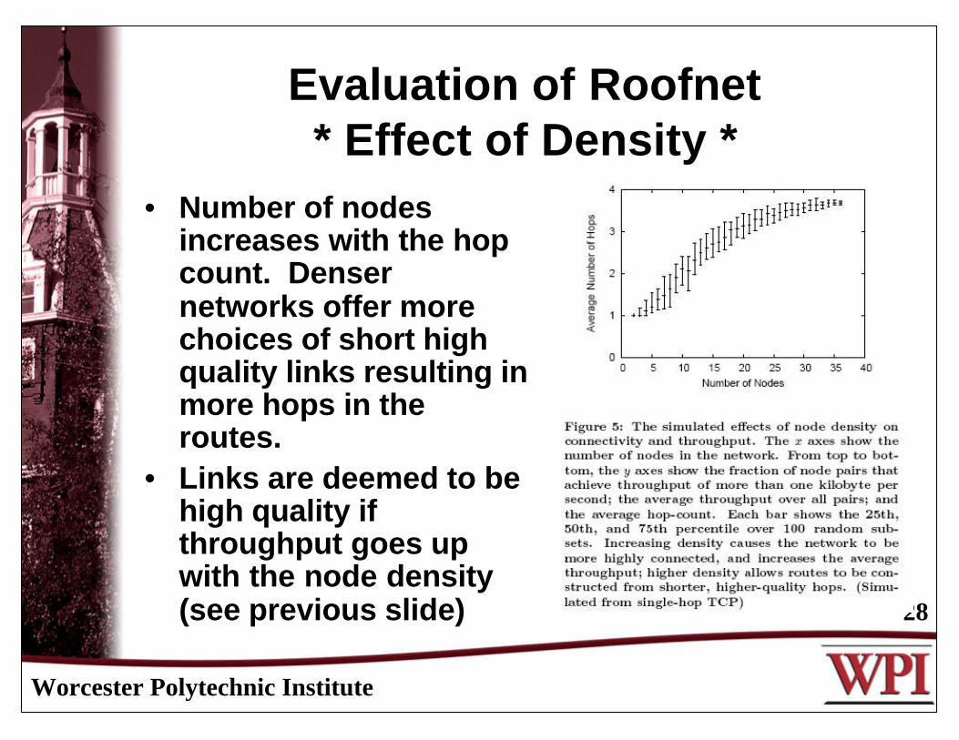
• Number of nodes increases with the hop count. Denser networks offer more choices of short high quality links resulting in more hops in the routes.
• Links are deemed to be high quality if throughput goes up with the node density (see previous slide)
Worcester Polytechnic Institute
29
Evaluation of Roofnet* Mesh Robustness *
• Mesh robustness measures benefits of routing choices resulting from using a mesh architecture and omni-directional antennas
• How to measure mesh robustness?– Determine how many potentially
useable neighbors each node has– Determine the extent the network is
vulnerable to the loss of its most valuable links

Worcester Polytechnic Institute
30
Evaluation of Roofnet* Mesh Robustness *
• Regarding fig. 6– Most nodes have many
neighbors.– Few are poorly
connected.
• Regarding fig. 7– Neighbors are only of
value if they are used.– Some nodes don’t use
all of their neighbors but a majority use more than 2 neighbors.

Worcester Polytechnic Institute
31
Evaluation of Roofnet* Mesh Robustness *
• Impact of losing valuable links (4 methods to compare) – Most Effect = delete links
that effect avg throughput the most.
– Long X Fast = delete links with highest product of distance and throughput.
– Fastest = delete links with highest throughput.
– Random = average of 40 simulations where links were deleted randomly.

Worcester Polytechnic Institute
32
Evaluation of Roofnet* Mesh Robustness *
• Results:– Deleting more effective links
considerably reduces throughput and connectivity over random deletion.
– Removing a few of the best connected nodes had greatest impact on throughput after they were deleted, the effect of deleting others after was less dramatic.
Worcester Polytechnic Institute
33
Evaluation of Roofnet* Architecture Alternatives *
• Analyzed choosing gateway locations vs. randomly choosing them
• Results– Careful choosing results in greater throughput
for multi-hop and single hop– For a smaller number of gateways random
multi-hop performs better than carefully chosen single hop gateways.
– For large number of gateways carefully chosen single hops are better than the random multi-hop gateways.

Worcester Polytechnic Institute
34
Evaluation of Roofnet* Inter-hop Interference *
• Multi-hop links slower than expected when compared to single-hop
• Most likely due to packet loss due to concurrent transmissions on different hops colliding
• Delaying sending give packets time to reach the destination and increased throughput.
• TRTS/CTS didn’t improve performance. 802.11 networks uses it to prevent collisions.
Worcester Polytechnic Institute
35
Roofnet Network Use
• User activity measured by monitoring TX/RX packets on one of 4 Roofnet gateways between Roofnet and the Internet
• Statistics:– 24 hour period – speed was 160 kbps between Roofnet and
Internet. 94% were wireless data traffic and 5% were protocol control packets
– 48% of data traffic was sent from nodes 1 hop from gateway; 36% for two hops; 16% for three hops or more
– Gateway radio busy about 70% of 24 hour monitoring period– More than 99% of the packets were TCP– Biggest bandwidth consumer (30%) during this time frame was
BitTorrent peer to peer file sharing program– 68% of connections through the gateway were web
connections although requests only comprised 7% of the bytes transmitted
Worcester Polytechnic Institute
36
Related work
• Several evaluations of deployed multi-hop wireless networks.– Focused on improving routing in static mesh networks or route
repair due to mobility issues.• Roofnet unique because:
– evaluates a deployed mesh with active users– considers effects of arch. decisions and not protocol design.
• Roofnet expanded on existing protocols and technology • Community mesh wireless networks exist:
– Seattle Wireless, San Francisco’s BAWUG, the SouthamtonOpen Wireless Network, among others.
• Commercial mesh Internet access technologies exist.– Eg. MeshNetworks Inc., Ricochet, and Tropos networks.
Worcester Polytechnic Institute
37
Conclusions
• The network architecture described in this paper favors:– Ease of deployment due to omni-directional antennas– Self-configuring software– Link-quality-aware multi-hop routing
• Volunteer participation grew network to 37 nodes in the course of a year.
• Performance of the network shows that it works well:– Average throughput between nodes is 627 kbps.– Only a few internet gateways needed – Position of nodes is based on convenience not by network
design.• Roofnet’s Multi-hop mesh network increases connectivity
and throughput over a hypothetical single-hop network• For more information on Roofnet see
http://pdos.csail.mit.edu/roofnet/doku.php.
Worcester Polytechnic Institute
38
Conclusions
• Roofnet is being used by several communities– Roofnet Cambridge, MA– TentCity in Boston, MA– NetEquality, Portland, OR
• Questions?