preserve ip addresses during data center migration white paper
TRANSCRIPT

© 2015 Cisco and/or its affiliates. All rights reserved. This document is Cisco Public Information. Page 1 of 90
White Paper
Preserve IP Addresses During Data Center Migration
Configure Cisco Locator/ID Separation Protocol
and Cisco ASR 1000 Series Aggregation
Services Routers

© 2015 Cisco and/or its affiliates. All rights reserved. This document is Cisco Public Information. Page 2 of 90
Contents
Executive Summary ................................................................................................................................................. 4 Cisco Services ...................................................................................................................................................... 5
Introduction .............................................................................................................................................................. 5
Benefits of Keeping the Server IP Address During Data Center Migrations ...................................................... 7 Existing Challenges .............................................................................................................................................. 7 Benefits of LISP for Data Center Migrations ......................................................................................................... 8
Layer 3-Based Data Center Migration .................................................................................................................... 9 LISP and OTV Coexistence .................................................................................................................................. 9
Scope ........................................................................................................................................................................ 9
Terminology ........................................................................................................................................................... 10
Solution Overview.................................................................................................................................................. 10 Solution Considerations ...................................................................................................................................... 11 Transparent Integration into Existing Production Network .................................................................................. 11 Map Server and Map Resolver Placement.......................................................................................................... 12 Transport Network .............................................................................................................................................. 12 Routing Considerations ....................................................................................................................................... 12 LISP Routing through Stretched Subnets ........................................................................................................... 13 No Changes to Virtual or Physical Servers ......................................................................................................... 13 Traffic Symmetry: Firewall and Load-Balancer Considerations ........................................................................... 13 Selecting the Cisco ASR 1000 Series Option ..................................................................................................... 13 Scalability and Latency ....................................................................................................................................... 14 Using a Non-LISP Device as the Default Gateway in the New Data Center ....................................................... 14
Deploying LISP on Cisco ASR 1000 Series for Data Center Migration ............................................................. 14 Implementation Details for the Brownfield (Source) Data Center ........................................................................ 15 Detection of Source Data Center EIDs with Cisco Embedded Event Manager Script ......................................... 16 Implementation Details for the Greenfield (New) Data Center ............................................................................ 16 Connectivity between the Cisco ASR 1000 Series LISP Routers ....................................................................... 17 Discovery of Servers and Registration with the Map Servers ............................................................................. 17 Traffic Flows ........................................................................................................................................................ 19 Configuring the Source Site Cisco ASR 1000 Series Router as a LISP PxTR .................................................... 24 Configuring the Destination Site Cisco ASR 1000 Series Router as a LISP xTR, Map Server, and Map Resolver ............................................................................................................................................................................ 26 Multicast Configuration for LISP Map-Notify Messages in a Multihomed Environment ....................................... 29
Configuration Examples ........................................................................................................................................ 30 Source Data Center Cisco ASR 1000 Routers .................................................................................................... 30 Detecting EIDs with EEM Scripts ........................................................................................................................ 37 Destination Data Center Cisco ASR 1000 Routers ............................................................................................. 39
Verification and Traffic Flows for the Stages of Migration ................................................................................. 45 Initial State: LISP Routers Have Been Implemented, but Servers Have Not Migrated ........................................ 45
Verify That the PxTRs Have Detected the Dynamic EIDs (Servers Still in Source Data Center) .................... 46
Verify That the Dynamic EIDs Detected in the Source Data Center Have Registered with the Map Servers . 48
Midmigration State: Some Servers Have Migrated to the Destination Data Center ............................................ 50 Verify That the xTR-MSMRs Have Detected the Dynamic EIDs (Servers That Have Migrated) ..................... 50
Verify That the Dynamic EIDs’ EID-to-RLOC Mapping Database Has Been Updated on Map Servers for
Servers That Have Migrated ........................................................................................................................... 52
Generate Traffic between a Migrated Server and a Server Still in the Source Data Center ............................ 54
© 2015 Cisco and/or its affiliates. All rights reserved. This document is Cisco Public Information. Page 3 of 90
Generate Traffic between a Migrated Server and the WAN ............................................................................ 57
End-of-Migration State: All Servers Have Migrated to the Destination Data Center ............................................ 59 Verify That the xTR-MSMRs Have Detected the Dynamic EIDs (Servers That Have Migrated) ..................... 59
Verify That the Dynamic EIDs’ EID-to-RLOC Mapping Database Has Been Updated on Map Servers for
Servers That Have Migrated ........................................................................................................................... 61
End-of-Migration Steps to Decommission LISP Routers ................................................................................... 62 Step 1: Move the Default Gateway for Servers to the New Data Center Switches ............................................. 62
Step 1.1: Add VLAN 4000 Interfaces on the Aggregation Switch in the New Data Center. ............................. 62
Step 1.2: - Note that Before Starting Step 1.2, be Aware that Step 1.2 and Step 1.3 Need to be Done in Quick
Succession. After Verifying that the Destination Data Center Switches are in the Listen State for the Same
HSRP Group as the xTR-MSMRs, Increase the HSRP Priority of the Switches so that they Preempt the xTR-
MSMRs and Become HSRP Active and Standby............................................................................................ 63
Step 1.3: Remove the HSRP Configuration on the xTR-MSMRs for VLAN 4000. .......................................... 63
Step 2: Advertise the Route for the Migrated Subnet from the Destination Data Center ..................................... 64 Step 2.1: Advertise the Subnet to the WAN from the Destination Data Center. .............................................. 64
Step 2.2: Shut Down the Subnet’s VLAN Interface on the Aggregation Switches in the Source Data Center. 64
Step 2.3: Stop Advertising the Subnet to the WAN from the Source Data Center. ......................................... 64
Failure and Recovery Analysis ............................................................................................................................. 65 Using Route Watch to Track the Reachability of Remote ETRs ......................................................................... 65 HSRP Tracking to Force Failover When ITR Loses Both Routes to Remote ETRs ............................................ 68 EEM Scripts to Force Failover of Incoming LISP Traffic When the Internal Interface on the Primary ETR Goes Down ................................................................................................................................................................... 70 Failover of Traffic between a Server in the Destination Data Center and a WAN Site Not Enabled for LISP ..... 72
Optional Deployment Variations .......................................................................................................................... 74 Environments with Multiple VRF Instances ......................................................................................................... 75 LISP Coexistence with OTV ................................................................................................................................ 77 Nonredundant Deployments ............................................................................................................................... 79 Secondary IP Addressing.................................................................................................................................... 79
Support for Stateful Devices ................................................................................................................................. 81 Firewall Placement between Aggregation and Core Layers ............................................................................... 82 Firewall Placement between Servers and Aggregation Layer ............................................................................. 83
Steps for Troubleshooting LISP Mobility ............................................................................................................. 86 Step 1: Verify the Underlay Routing .................................................................................................................... 86 Step 2: Verify the LISP Control Plane ................................................................................................................. 86
Step 2.1: Verify that the ETR has Detected the Dynamic EIDs. ...................................................................... 86
Step 2.2: Verify that the ETR has Registered the EIDs with the Map Server. ................................................. 86
Step 2.3: Verify that ITR Adds an Entry in its Map Cache when Traffic is Sent to the Destination EID. .......... 87
Step 3: Verify the LISP Data Plane ..................................................................................................................... 87 Step 3.1: Check the Hardware Forwarding Table (Cisco Express Forwarding [CEF] Table). ......................... 87
Step 3.2: Verify that ITR is LISP Encapsulating the Data Packets. ................................................................. 87
Step 3.3: Verify that ETR is Receiving the LISP-Encapsulated Data Packets. ............................................... 87
Conclusion ............................................................................................................................................................. 87
Appendix: Overview of LISP ................................................................................................................................. 88 Locator/Identifier Separation Protocol ................................................................................................................. 88 LISP Basic Concepts .......................................................................................................................................... 89
For More Information ............................................................................................................................................. 90
© 2015 Cisco and/or its affiliates. All rights reserved. This document is Cisco Public Information. Page 4 of 90
Executive Summary
Data center migration projects usually are complex and involve careful planning and coordination between multiple
teams, including application, server, network, storage, and facilities teams. It’s common to hear that a data center
migration project is taking longer than expected, and that the need for coordination between network and
application or server teams was one of the reasons for the delay.
The traditional ways of performing data center migrations have limitations that often lead to delays and high costs.
Here are some of the traditional methods and their limitations:
● Application migration with IP address change: This type of migration is expensive and difficult to perform
because it requires full documentation of existing application interactions. In addition, the IP address
change results in a migration with considerable associated complexity. Many applications, particularly
traditional applications, still have IP addresses hard coded into the application, so changing their IP
addresses requires a rewrite the application, which is often expensive to do and has a high risk.
● Physical migration of the server network by repatching or rebuilding the source (existing) network as an
extension to target (new) data center: This type of migration is complex because it requires you to collect a
large volume of data before the project start. In addition, in some cases, conflicting VLAN numbers between
the source and target networks add to the complexity. Usually this approach involves the movement of
existing servers, which does not allow initiatives such as server virtualization to occur together with the data
center migration project, requiring additional subsequent projects.
● Migration of the entire data center: This type of migration usually is not viable because it requires you to
collect a large volume of data before the project start, it has high risk, and it requires an outage of the entire
data center during the migration event. This approach often requires a large workforce.
A better solution for data center migrations is one that allows customers to migrate servers with IP mobility and that
also removes the affinity-group constraints of traditional approaches: that is, that lets you move a server (physical
or virtual) and keep the IP address, subnet mask, default gateway, and host name. Such a solution also allows you
to decouple the server migration process and schedule from network constraints.
This document describes a new solution for data center migration. It uses Cisco® Locator/ID Separation Protocol
(LISP) technology (RFC 6830) running on Cisco ASR 1000 Series Aggregation Services Routers, and it simplifies
and accelerates data center migration. Here are some of the benefits this solution delivers:
● You can decouple the server migration activities (planning, affinity-group migration, schedules, cutovers,
etc.) from network constraints.
● The solution provides IP address mobility: the IP address, subnet mask, default gateway, and host name of
migrated servers do not need to change.
● You can implement migration in small groupings, enabling even a single-server migration (if required), or
the migration of a group of servers.
● The hardware cost is lower than for alternative solutions, with just four devices required.
Customers who have adopted this solution were able to perform a data center migration more quickly and with
much lower risk. In fact, some customers expect to reduce the migration window by up to 95 percent.

© 2015 Cisco and/or its affiliates. All rights reserved. This document is Cisco Public Information. Page 5 of 90
Cisco Services
The Cisco Services team is available to assist with the planning, design, deployment, support, and optimization of
the solution described on this document.
Effective design is essential to reducing risk, delays, and the total cost of network deployments. Cisco Services can
deliver a high-level design or an implementation-ready detailed design for the solution described in this document.
Integration of devices and new capabilities without compromising network availability or performance is critical to
success. Cisco Deployment Services can help by providing expert assistance to develop implementation plans and
to install, configure, and integrate the solution described here into your production network. Services include
project management, post-implementation support, and ongoing knowledge transfer. After deployment, Cisco
Optimization Services can help ensure that your deployment continues to run optimally.
Cisco Services for the solution described here are available globally and can be purchased from Cisco and Cisco
Certified Partners. Service delivery details may vary by region and may differ depending on the service options that
you choose. For more information about Cisco Services, visit http://www.cisco.com/go/services.
Introduction
This document explains a network solution based on Cisco Locator/ID Separation Protocol (LISP) technology
(RFC 6830) that helps you accelerate data center migration projects and make them run more smoothly.
The target of this solution is the scenario in which a customer has a source environment, usually a data center, and
a destination environment, usually a target data center, and is trying to migrate servers from the source to the
destination data center.
One common requirement in this scenario is the capability to migrate the servers without making any changes to
their IP configuration. In particular, server administrators want to avoid changing the server IP address, subnet
mask, and default gateway settings.
You can use LISP to address this requirement (Figure 1). Server 10.1.1.7 is moved to the destination data center
while the other servers in the same subnet remain active in the source data center. No changes are required in the
server 10.1.1.7 IP setting.
Figure 1. Nonintrusive Insertion of LISP Data Center Migration Routers

© 2015 Cisco and/or its affiliates. All rights reserved. This document is Cisco Public Information. Page 6 of 90
LISP separates location and identity, thus allowing the migration or creation of new servers in the target data
center with the same IP address (identity of the server), subnet mask, and default gateway configurations as the
server used in the source data center. The details of how the solution works are described in other sections of this
document. Essentially, though, when a server is moved, the LISP router updates in its database the endpoint
ID-to-router locator (EID-to-RLOC) mapping of the server to reflect the new location. In this example, that location
is the target data center. No changes are required to the end systems, users, or servers, because LISP handles
the mapping between identity (server IP address) and location (source or target data center) invisibly to the users
trying to reach the server.
LISP operates as an overlay, encapsulating the original packets to and from the server into a User Datagram
Protocol (UDP) packet along with an additional outer IPv4 or IPv6 header, which holds the source and destination
RLOCs. This encapsulation allows the server in the target data center to use the same IP address that existed in
the source data center, removing the constraint of having a subnet present in only a single location. The LISP
encapsulated packets can cross multiple Layer 3 boundaries and hops.
Another important property of LISP that is relevant to safer, lower-risk data center migration is IP portability.
LISP enables IP portability by routing (Layer 3) to the right location where the server is, providing total isolation of
broadcast (Layer 2) domains between the source and destination data centers.
Sites not enabled for LISP communicate with the servers moved to the target data center through the source data
center where LISP is deployed. The solution documented here does not require LISP to be enabled globally.
The solution instead is deployed by enabling LISP in just the source and destination data centers, with little impact
on the operations of either site.
The optional deployment of LISP at remote sites (branch offices) provides data-path optimization, because the
LISP-encapsulated traffic is routed directly to the data center in which the target server is located.
In the solution documented here, IP mobility service (enabled by LISP) is provided in the network by a Cisco ASR
1000 Series router and supports all kinds of servers, physical or virtual. For virtual servers, the solution supports
any hypervisor.
The ASR 1000 Series router that supports LISP and that is deployed in the source data center does not need to be
the default gateway for the local servers (physical and virtual machines). Therefore, this solution can be introduced
nondisruptively into an existing production environment.
In summary, the goal of the solution explained here is to allow a customer to move servers (physical or virtual)
between data centers while keeping their IP address, subnet mask, and default gateway and without requiring
changes in firewall rules and other access lists.
The next sections discuss the needs and benefits that LISP provides for data center migration. The document then
positions LISP as the technology for enabling IP mobility to extend Layer 2 between data centers. This document
also provides a solution overview, steps for deploying this solution, and failure scenarios and discusses
convergence time.

© 2015 Cisco and/or its affiliates. All rights reserved. This document is Cisco Public Information. Page 7 of 90
Benefits of Keeping the Server IP Address During Data Center Migrations
Server and applications teams typically prefer to keep the same server IP address during data center migrations.
The LISP solution makes this possible.
Existing Challenges
Without a solution that provides IP mobility, moving a server or application to a new data center requires changes
in the IP address, default gateway, and host name.
In this case, it takes longer to start moving servers because data must be collected, and application interfaces,
interactions, and traffic flows must be documented. This approach also is complex, with the need to maintain
interfaces and flows and monitor the effects of the migration even on systems that are not moved or migrated.
Figure 2Error! Reference source not found. shows that a change in the address affects several communication
flows. Domain Name System (DNS) updates may not always help with existing applications if the IP address is
hard coded. Applications local and remote may need to be modified, as may firewall rules. The risk associated with
such changes can be significant.
Figure 2. Challenges with Server Migrations
Another consideration when migrating servers is that some servers have multiple interfaces. For example, a server
may have an interface for production traffic, another for management, and another for backup and restore
operations, as illustrated in figure 3. Without IP mobility, if you do not want to change the IP addresses of the
servers, you must move all the servers in a subnet together. However, as illustrated in the figure, this means that
you must move a large number of servers together, making this approach especially complex.

© 2015 Cisco and/or its affiliates. All rights reserved. This document is Cisco Public Information. Page 8 of 90
Figure 3. All Servers in Subnets A, B, and C Would Need to Be Migrated Together
Benefits of LISP for Data Center Migrations
The LISP solution proposed here, which retains the server IP address during data center migrations, has these
main benefits:
● You can perform server migrations in much smaller increments, which lowers the risk of the project. Even
just a single server can be migrated without affecting any other server in any subnet to which that server is
connected.
● Server migrations can begin much faster: as soon as the data for that server is available in target data
center.
● Less data needs to be kept synchronized, reducing risk and WAN requirements.
● Path optimization from the user to the application is possible, eliminating latency concerns and reducing
WAN bandwidth requirements. This benefit requires adoption of LISP at remote sites.
● Affinity-group constraints are removed. Each server can be migrated independently.
Table 1 demonstrates the impact of LISP on data center migration by comparing an existing approach that
provides no IP mobility and LISP, in which a server keeps its IP address during data center migration.
Table 1. Comparison of Migration with and Without LISP
Traditional Approach (Without IP Mobility)
LISP (with IP Mobility)
Impact of LISP on Data Center Migration
Migration increments (number of servers to be migrated at the same time)
Smallest chunk that can be migrated is all the servers in the same subnet: usually a large number of servers
Smallest chunk that can be migrated is a single server
Lower risk;
servers can be migrated faster with less dependency
When can servers in target data center begin being activated?
Only after all data for all servers in the same subnet is migrated to target data center
As soon as the data for a single server is available, that server can be moved
Servers can be activated in target data center much sooner than before; reduces the amount of time large data sets have to be kept synchronized
Impact on latency and application performance
Path optimization from the end user to the server not easily achievable
Direct access from the end user to new server located on target data center is possible
Reduces latency concerns and WAN bandwidth requirements

© 2015 Cisco and/or its affiliates. All rights reserved. This document is Cisco Public Information. Page 9 of 90
Layer 3-Based Data Center Migration
Layer 2 (VLAN) extension can also be used to provide IP mobility during data center migrations. However, the
need for a Layer 3-based (routing based) solution that provides IP mobility is growing because customers prefer
not to extend the broadcast domain (Layer 2) between their environments.
The main difference between Layer 2-based technologies, such as Cisco Overlay Transport Virtualization (OTV)
and Virtual Private LAN Service (VPLS), and LISP, which provides a Layer 3-based solution, is that with LISP the
broadcast or Layer 2 failure domain is not extended between sites. LISP does not propagate broadcasts, whereas
with Layer 2-based solutions broadcast packets are flooded.
Another consideration is that a pair of devices enabled for OTV devices would usually connect to a single pair of
aggregation switches because they are connected at Layer 2. However, with LISP a single pair of routers enabled
for LISP can connect to multiple aggregation blocks in the source and destination data centers; because they are
connected at Layer 3, there is not a risk of bridging between aggregation blocks.
Note that Layer 2 solutions allow cluster members that require Layer 2 connectivity to be stretched between data
centers. LISP does not support this capability because it does not flood Layer 2 broadcasts or link local multicast
packets.
Live-migration applications (for example, VMware vMotion) also require Layer 2 connectivity between hosts, and
therefore are supported only by Layer 2-based solutions. The LISP solution presented here supports cold migration
between data centers.
LISP and OTV Coexistence
LISP supports a deployment mode called extended subnet mode, in which LISP is used for the same VLAN and
subnet as a LAN extension solution (for example, OTV or VPLS). In this case, LISP provides path optimization, and
the LAN extension solution provides IP mobility. The solution presented here does is not use LISP extended
subnet mode. However, as documented in the section “LISP Coexistence with OTV” you can combine OTV and
LISP on the same ASR 1000 Series router, with OTV used for some VLANs, and LISP used for others. For
example, OTV may be used to extend VLAN 10, which has subnet 10.10.10.0/24 configured on it, and LISP may
be used to provide IP mobility for subnet 10.20.20.0/24 in VLAN 20. Note that LISP does not extend VLANs.
Therefore, the VLAN ID is irrelevant for forwarding using LISP.
Some customers are taking the approach “route when you can, and bridge when you must.” For this approach, a
Layer 3-based data center migration as presented in this document is required.
Scope
This document describes a solution that allows servers to be migrated while keeping their IP addresses, subnet
masks, and default gateways. The solution is based on Cisco LISP running on the Cisco ASR 1000 Series routers
deployed at the source and destination data centers.
This solution requires the ASR 1000 Series router running Cisco IOS®
XE Software Release 3.10 or later with the
Cisco Advanced IP Services or Advanced Enterprise Services feature set.
Although not described directly in this document, a Cisco Cloud Services Router (CSR) 1000V running Cisco
IOS XE Software Release 3.11 or later with the Cisco Premium or AX license package can be used with the same
results.

© 2015 Cisco and/or its affiliates. All rights reserved. This document is Cisco Public Information. Page 10 of 90
LISP is supported on several other Cisco platforms. However, the use of other routers and switches that support
LISP to provide the solution described here is outside the scope of this document, and their implementation of
LISP may vary from the implementation on Cisco IOS XE Software used by the ASR 1000 and CSR 1000V Series.
Terminology
This section defines some of the main terms used in this document. These terms are described in more detail
elsewhere in the document.
● Cisco Cloud Services Router (CSR) 1000V: Cisco’s virtual router offering, which you can deploy in private,
public, or hybrid cloud environments
● Cisco Locator/ID Separation Protocol (LISP): A tunnel protocol that uses a central database in which
endpoint location is registered; LISP enables IP host-based mobility for endpoints
● LISP-enabled virtualized router: A virtual machine or appliance that supports routing and LISP functions,
including host mobility
● Endpoint ID (EID): IPv4 or IPv6 identifier of the devices connected at the edge of the network; used in
the first (innermost) LISP header of a packet
● Routing locator (RLOC): IPv4 or IPv6 addresses used to encapsulate and transport the flow between
LISP nodes
● Ingress tunnel router (ITR): A router that has two functions: it resolves the location of an EID by querying
the database, and then it performs the encapsulation to the remote RLOC
● Egress tunnel router (ETR): A router that has two functions: it registers the endpoint or location associated
with the database, and then it decapsulates the LISP packet and forwards it to the right endpoint
● xTR: A generic name for a device performing both ITR and ETR functions
● Proxy-ITR (PITR): A router that acts like an ITR but does so on behalf of non-LISP sites that send packets
to destinations at LISP sites
● Proxy-ETR (PETR): A router that acts like an ETR but does so on behalf of LISP sites that send packets to
destinations at non-LISP sites
● PxTR: A generic name for a device that performs both PITR and PERT functions
Solution Overview
Data center migration requires the mobility of any workload with IP address retention, in a plug-and-play solution,
independent of the server type and hypervisor. It must allow partial migration, which means keeping a full IP subnet
active on both existing (brownfield) and new (greenfield) data centers at the same time. In addition, IP mobility
must be implemented over a totally safe connection without extending the fault domain from one site to the other.
In the proposed solution, LISP offers routed IP mobility: that is, a stretched subnet connection with Layer 3 mobility.
LISP is a host-based routing technology that uses a central database and local caching to enable IP
intercommunication. For more information about LISP, see the “Appendix: Overview of LISP” section in the
appendix of this document.

© 2015 Cisco and/or its affiliates. All rights reserved. This document is Cisco Public Information. Page 11 of 90
Figure 4 shows a LISP topology.
Figure 4. Reference Topology
Solution Considerations
Migration is performed from an existing, brownfield data center to a new, greenfield data center.
No constraints are imposed on either of these data centers.
Usually the existing data center is built on the standard aggregation- and access-layer architecture, and the new
data center either uses the same topology or a fabric approach, with a spine-and-leaf design. However, in fact, the
solution exposed in this document requires only access to the data center VLANs without constraint on the internal
design.
Transparent Integration into Existing Production Network
To interconnect the data center, the data center interconnect (DCI) uses two pairs of LISP nodes deployed “on a
stick” in each data center. It uses an IP connection between that could be the IP infrastructure of the enterprise, or
a direct connection from a LISP node to another LISP node when the migration occurs over a short distance.

© 2015 Cisco and/or its affiliates. All rights reserved. This document is Cisco Public Information. Page 12 of 90
The concept of “on a stick” deployment relies on devices that are not inserted into the common data path and so
are not used by the main application sessions. The LISP connection will be used only for the workload being
migrated. The devices are connected with two links: one to the core to simply allow IP to run and which the LISP
encapsulated packet will traverse, and another in VLAN trunk mode and which must be connected to the
distribution layer or to a leaf node to get access to the subnets in migration.
This design uses several LISP functions, but they all reside in just two pairs of physical devices. There is no need
for any LISP deployment anywhere else.
On the brownfield data center ASR 1000 Series (or CSR 1000V Series) pair:
● Proxy Address Resolution Protocol (proxy-ARP): The LISP node will respond to ARP directed to any
migrated workload, which attracts traffic to LISP.
● PITR: Get the flow from any source to be transported by LISP.
● PETR: Attract traffic that returns from the new data center to help ensure a symmetrical path, if needed.
On the greenfield data center ASR 1000 Series (or CSR 1000V Series) pair:
● Default-Gateway: During the migration, the ASR 1000 Series router is the gateway for the subnet under
migration.
● ETR: This router transmits traffic coming from LISP to the data center.
● ITR: This router transmits traffic coming from the data center to LISP.
● Use-PETR: This option forces all traffic to return to the original data center.
Map Server and Map Resolver Placement
The LISP database, composed of the map server (MS) and map resolver (MR), must be hosted on one pair of
devices. This database could be anywhere, but the discussion in this document, it is hosted on the greenfield side.
Transport Network
For the solution described here, the only requirement for the transport network is that it must provide IP
connectivity between the LISP-enabled routers located in the source and destination data centers. This network is
referred to as the transport network.
The transport network can be IP based or Multiprotocol Label Switching (MPLS) based. So long as there is IP
connectivity between the LISP-enabled routers, the solution works. The IP connectivity can be provided by
dedicated links interconnecting the sites as shown earlier in figure 4, or the LISP flows can traverse the WAN.
Routing Considerations
As stated earlier, the LISP nodes just must be reachable from each other over an IP network. If this IP connection
is the enterprise network, you need to consider two factors: the maximum transmission unit (MTU) size and fast
convergence.
LISP encapsulates packets under UDP and extends their size. LISP adds 36 bytes for IPv4 and 56 bytes for IPv6
encapsulation. LISP tunneling does support dynamic MTU adaptation through Path Maximum Transmission Unit
Discovery (PMTUD), and LISP nodes do support packet fragmentation, but the easiest way to achieve reachability
is for the IP network to support a large MTU.
© 2015 Cisco and/or its affiliates. All rights reserved. This document is Cisco Public Information. Page 13 of 90
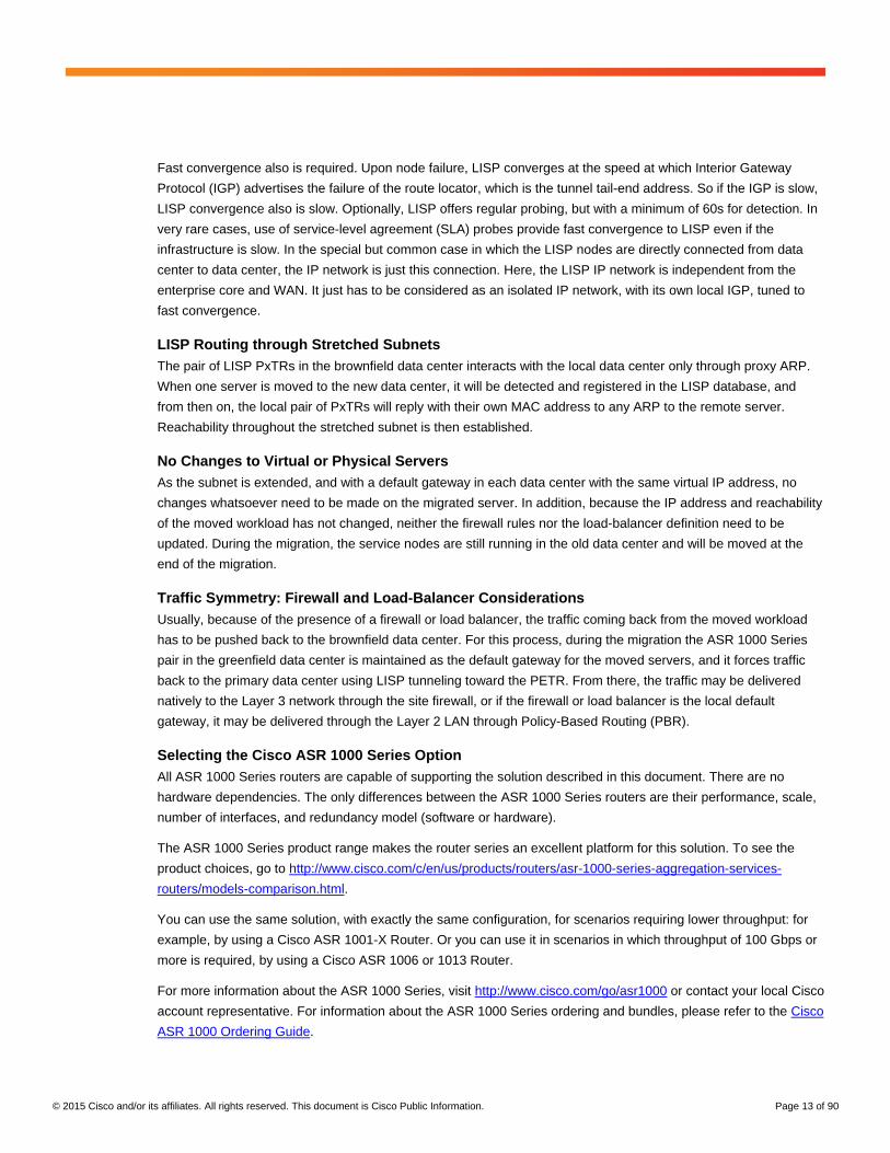
Fast convergence also is required. Upon node failure, LISP converges at the speed at which Interior Gateway
Protocol (IGP) advertises the failure of the route locator, which is the tunnel tail-end address. So if the IGP is slow,
LISP convergence also is slow. Optionally, LISP offers regular probing, but with a minimum of 60s for detection. In
very rare cases, use of service-level agreement (SLA) probes provide fast convergence to LISP even if the
infrastructure is slow. In the special but common case in which the LISP nodes are directly connected from data
center to data center, the IP network is just this connection. Here, the LISP IP network is independent from the
enterprise core and WAN. It just has to be considered as an isolated IP network, with its own local IGP, tuned to
fast convergence.
LISP Routing through Stretched Subnets
The pair of LISP PxTRs in the brownfield data center interacts with the local data center only through proxy ARP.
When one server is moved to the new data center, it will be detected and registered in the LISP database, and
from then on, the local pair of PxTRs will reply with their own MAC address to any ARP to the remote server.
Reachability throughout the stretched subnet is then established.
No Changes to Virtual or Physical Servers
As the subnet is extended, and with a default gateway in each data center with the same virtual IP address, no
changes whatsoever need to be made on the migrated server. In addition, because the IP address and reachability
of the moved workload has not changed, neither the firewall rules nor the load-balancer definition need to be
updated. During the migration, the service nodes are still running in the old data center and will be moved at the
end of the migration.
Traffic Symmetry: Firewall and Load-Balancer Considerations
Usually, because of the presence of a firewall or load balancer, the traffic coming back from the moved workload
has to be pushed back to the brownfield data center. For this process, during the migration the ASR 1000 Series
pair in the greenfield data center is maintained as the default gateway for the moved servers, and it forces traffic
back to the primary data center using LISP tunneling toward the PETR. From there, the traffic may be delivered
natively to the Layer 3 network through the site firewall, or if the firewall or load balancer is the local default
gateway, it may be delivered through the Layer 2 LAN through Policy-Based Routing (PBR).
Selecting the Cisco ASR 1000 Series Option
All ASR 1000 Series routers are capable of supporting the solution described in this document. There are no
hardware dependencies. The only differences between the ASR 1000 Series routers are their performance, scale,
number of interfaces, and redundancy model (software or hardware).
The ASR 1000 Series product range makes the router series an excellent platform for this solution. To see the
product choices, go to http://www.cisco.com/c/en/us/products/routers/asr-1000-series-aggregation-services-
routers/models-comparison.html.
You can use the same solution, with exactly the same configuration, for scenarios requiring lower throughput: for
example, by using a Cisco ASR 1001-X Router. Or you can use it in scenarios in which throughput of 100 Gbps or
more is required, by using a Cisco ASR 1006 or 1013 Router.
For more information about the ASR 1000 Series, visit http://www.cisco.com/go/asr1000 or contact your local Cisco
account representative. For information about the ASR 1000 Series ordering and bundles, please refer to the Cisco
ASR 1000 Ordering Guide.

© 2015 Cisco and/or its affiliates. All rights reserved. This document is Cisco Public Information. Page 14 of 90
Scalability and Latency
The migration nodes - one pair per site - can be any device that supports LISP mobility. Devices validated so far
are the ASR 1000 Series and the CSR 1000V virtual router. Any combination of these devices is supported. Please
refer to the ASR 1000 Series products mentioned in the preceding section for more information about node choice
based on the throughput you need.
The solution described here has been validated to scale to support up to 5000 dynamic EIDs when deployed in an
ASR 1000 Series router.
Each ASR 1000 Series LISP node adds 30 microseconds of latency, which is negligible. However, you need to
consider the latency on the link that connects the sites.
Using a Non-LISP Device as the Default Gateway in the New Data Center
The solution in this document needs the default gateway of the greenfield site to be on the LISP XTR for the
workload under migration. Only at the end of migration can it be moved to the aggregation layer. This approach is
the recommended and tested design.
However, in some cases the default gateway in new data center needs to be on another device.
For instance, the brownfield data center may not have any firewall. In this case, symmetry of traffic is not required,
and the traffic on the greenfield side can exit naturally through routing. LISP encapsulation is not needed on the
return traffic, and the default gateway can be anywhere.
If the old data center has a firewall that requires symmetry of traffic, the LISP XTR on the new data center must
capture the return traffic. In this case, the default gateway has to force traffic across the LISP node in some way. A
default route or PBR on the source subnet under migration could be used.
Deploying LISP on Cisco ASR 1000 Series for Data Center Migration
The reference topology (Figure 5) shows two data centers. The source data center is the existing data center in
which the servers are currently located. The destination data center is the new data center to which the servers will
be migrated.
This example shows two server subnets, 10.1.1.0/24 and 10.1.2.0/24, which are in VLANs 200 and 201,
respectively, in the source data center. LISP mobility will be enabled on the ASR 1000 Series routers for these two
subnets, to allow servers to be migrated from the source to the destination data center. The destination data center
will have a new VLAN allocation scheme, so the subnets 10.1.1.0/24 and 10.1.2.0/24 will be in VLANs 4000 and
4001, respectively.
Note that this initial example doesn’t have any stateful devices such as load balancers or firewalls. The inclusion of
firewalls and load balancers in the topology is discussed in the section “Support for Stateful Devices” later in this
document.

© 2015 Cisco and/or its affiliates. All rights reserved. This document is Cisco Public Information. Page 15 of 90
Figure 5. Reference Topology with Sample Subnets to Be Migrated
Implementation Details for the Brownfield (Source) Data Center
The source data center consists of a traditional three-tier topology with servers connected to the access layer. The
default gateway for the servers is the aggregation switches. If Virtual Switching System (VSS) is supported, the
aggregation switches could use VSS, or the solution could run in standalone mode and use Hot Standby Router
Protocol (HSRP) for first-hop redundancy for the servers. The aggregation switches will advertise the server
subnets in a dynamic routing protocol and have routed Layer 3 interfaces facing the core devices. The core
devices will then advertise the server subnets to the WAN to attract traffic from the remote sites to the source data
center.
The ASR 1000 Series routers in the source data center will be configured as LISP PxTRs. The aggregation
switches will use IEEE 802.1Q trunks to connect to the PxTRs and trunk the server VLANs. The PxTRs will use
routed IEEE 802.1Q subinterfaces on these trunks for each server subnet that needs to be migrated.
The PxTRs will run HSRP for each server subnet to determine the active PxTR for egress traffic for each server
subnet. This HSRP group will be separate from the HSRP group used on the aggregation switches, and the
servers will not use the PxTRs as their default gateway. In this example, PxTR-01 is the HSRP active for both
server subnets.

© 2015 Cisco and/or its affiliates. All rights reserved. This document is Cisco Public Information. Page 16 of 90
LISP mobility will be enabled for the server subnets on the PxTRs. Hence, these subnets will be dynamic EID
subnets. A lower RLOC priority will be given to PxTR-01 for both dynamic EID subnets. PxTR-02 will be assigned a
higher RLOC priority for both dynamic EID subnets. Lower priority is preferred; hence, inbound LISP encapsulated
traffic will traverse PxTR-01 during normal circumstances.
The destination data center ASR 1000 Series routers will use source data center ASR 1000 Series routers as
proxy egress tunnel routers (PETRs). This approach allows servers that have been migrated to send traffic
destined for non-LISP subnets or remote sites through the source data center. This capability enables traffic to flow
symmetrically for servers that have migrated through any stateful devices in the source data center such as load
balancers and firewalls.
A separate IEEE 802.1Q subinterface on both PxTRs without LISP mobility enabled will be used for default
gateway routing. A /29 subnet will be used for this VLAN.
A static default route will be used on the PxTRs with the next hop as the aggregation switches’ HSRP virtual IP
address or switch virtual interface (SVI) for the VLAN if VSS is used. This subinterface will be used only for
outbound traffic to non-LISP subnets and remote sites. Because these subinterfaces will be used only for outbound
traffic from the PxTRs, HSRP is not required on the PxTRs for this subnet.
Detection of Source Data Center EIDs with Cisco Embedded Event Manager Script
For LISP mobility to function, the xTR must receive traffic from the servers to determine their locations. In the
source data center, the PxTRs are not the default gateway for the servers. Hence, for detection they depend on
receipt of broadcast traffic such as ARP requests from the servers. In most cases, this situation is not a problem
because servers regularly send broadcast ARP requests either to resolve the MAC address for other servers on
the subnet or to resolve the MAC address of the default gateway. However, a problem may occur if a server has
already resolved the MAC address of the default gateway before the PxTRs are added to the network. Subsequent
ARP requests from the server for the default gateway may be unicast to refresh the ARP cache.
Because the PxTRs are not the default gateway in the source data center, they may never learn about servers that
are not sending broadcasts. To solve this problem, a Cisco Embedded Event Manager (EEM) script can be used
on the primary PxTR to ping every IP address in the subnets enabled for LISP mobility. Before pinging each IP
address, the PxTR needs to send an ARP request for the address of the server. Each server that responds with an
ARP reply will be added to the PxTR’s local LISP database as a dynamic EID. This solution works even if the
server has a software firewall that blocks pings, because the PxTR can build its local LISP database based on the
ARP replies even without receiving an Internet Control Message Protocol (ICMP) reply.
Examples of EEM scripts are shown later, in the configuration section of this document.
Implementation Details for the Greenfield (New) Data Center
The destination data center is based on a modern spine-and-leaf architecture. The ASR 1000 Series routers in the
destination data center will be LISP xTRs and LISP mapping servers and map resolvers. The spine switches will
use IEEE 802.1Q trunks to connect to the xTR mapping servers and map resolvers and trunk the server VLANs.
The xTR mapping servers and map resolvers will use routed IEEE 802.1Q subinterfaces on these trunks for each
server subnet that needs to be migrated.

© 2015 Cisco and/or its affiliates. All rights reserved. This document is Cisco Public Information. Page 17 of 90
The xTR mapping servers and map resolvers will run HSRP for each server subnet to determine the active ITR for
egress traffic for each server subnet. This HSRP group will be the same as the HSRP group used on the
aggregation switches in the source data center, and the migrated servers will use the xTR mapping servers and
map resolvers as their default gateway for the duration of the migration. This approach allows the migrated servers
to use the same IP address and MAC address for their default gateway after they have been migrated. In this
example, xTR-MSMR-01 will be the HSRP active router for both server subnets.
LISP mobility will be enabled for the server subnets on the xTR mapping servers and map resolvers. Hence, these
subnets will be dynamic EID subnets. A lower RLOC priority will be given to xTR-MSMR-01 for both dynamic EID
subnets. xTR-MSMR-02 will be assigned a higher RLOC priority for both dynamic EID subnets. Lower priority is
preferred; hence, inbound LISP encapsulated traffic will traverse xTR-MS/MR-01 during normal circumstances.
Connectivity between the Cisco ASR 1000 Series LISP Routers
Each LISP router needs just Layer 3 IP reachability to the RLOC addresses of the other LISP routers. Therefore,
the solution is independent of Layer 1 and Layer 2. The connectivity between the ASR 1000 Series LISP routers
can be over any physical medium, such as dark fibre, dense wavelength-division multiplexing (DWDM), SONET, or
SDH. The connectivity could be over Layer 2 metro Ethernet, MPLS Layer 3 VPN, or the Internet. You can even
use the data center’s existing WAN links for IP connectivity between the LISP routers. Typically for a data center
migration, dedicated links are used for the duration of the migration. Dark fibre between the data centers is more
common for distances less than 10 km, whereas DWDM or metro Ethernet is more common for distances greater
than 10 km.
This example assumes dedicated Layer 1 or Layer 2 links between the ASR 1000 Series routers for the migration:
that is, the interfaces between the ASRs are Layer 2 adjacent and are on the same subnet. A loopback interface
will be used on each of the LISP routers for the RLOC. Open Shortest Path First (OSPF) will be used as the routing
protocol between the LISP routers. Bidirectional Forwarding Detection (BFD) can be used to improve convergence
if the ASRs are connected over a Layer 2 network such as metro Ethernet. OSPF should be enabled only on the
point-to-point links between the ASRs and the RLOC loopback interface. OSPF should not be enabled on the
subinterfaces connected to the data center switches, and the data center server subnets should not be announced
to OSPF.
Discovery of Servers and Registration with the Map Servers
The LISP PxTRs can be connected to the existing environments in the source and destination data centers
nonintrusively. No routing changes are required in the source data center. Because routed subinterfaces are used
on the PxTRs facing the aggregation switches, spanning tree isn’t needed. You should use spanning-tree
portfast trunk on the trunk ports on the aggregation switches facing the ASRs for faster convergence. LISP
mobility will be enabled on each server-facing subinterface on the PxTRs.
The PxTRs will not be the default gateway for the servers in the source data center. The HSRP active PxTR will
update its local LISP database based on broadcast packets such as the ARP requests it receives from servers in
the subnets in which LISP mobility is enabled. Each server detected will appear as a dynamic EID in the local LISP
database. The HSRP active PxTR will send multicast LISP map-notify messages back out the interface on which
the server was detected. The HSRP standby PxTR will update its local LISP database based on the information in
the map-notify messages received from the active PxTR.

© 2015 Cisco and/or its affiliates. All rights reserved. This document is Cisco Public Information. Page 18 of 90
Both PxTRs will send map-register messages to both map servers, which are the LISP xTR-MSMR routers in the
destination data center. The map servers will update the EID-to-RLOC mapping database based on the information
in the map-register messages. This information includes the RLOCs and their priority and weight values for each
EID. Initially, when no servers have been migrated, the RLOC addresses for all EIDs registered in the EID-to-
RLOC mapping database will be the RLOC addresses of the two PxTRs. See Figure 6.
Figure 6. Discovery of Servers and Registration with Map Servers
As in the source data center, the destination data center xTR-MSMR routers will be connected to the spine
switches over a IEEE 802.1Q trunk with routed subinterfaces on the xTR-MSMRs. Hence, there is no spanning-
tree interaction. Similarly, you should use spanning-tree portfast trunk on the ports on the spine switches facing
the ASRs for faster convergence. Each subinterface on the xTR-MSMRs will be for the new server VLANs in the
destination data center and will have LISP mobility enabled.
When a server is migrated to the new data center, it will send ARP requests for its default gateway. In the
destination data center, the default gateway for the servers will be the xTR-MSMR routers. The xTR-MSMSR
routers will update their local LISP database to include the server that has sent an ARP request. They will then
update the map-server EID-to-RLOC mapping database, which is stored locally because these routers are the map
servers. They will then send a map-notify message to the PxTRs to indicate that the server is now located in the
destination data center. The PxTRs will remove this server from the local LISP database and send a Gratuitous
ARP (GARP) request out the subinterface for the VLAN in which the server previously resided.
© 2015 Cisco and/or its affiliates. All rights reserved. This document is Cisco Public Information. Page 19 of 90
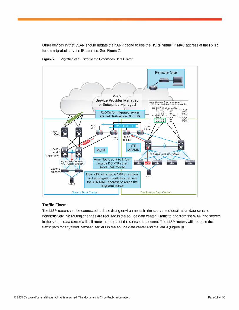
Other devices in that VLAN should update their ARP cache to use the HSRP virtual IP MAC address of the PxTR
for the migrated server’s IP address. See Figure 7.
Figure 7. Migration of a Server to the Destination Data Center
Traffic Flows
The LISP routers can be connected to the existing environments in the source and destination data centers
nonintrusively. No routing changes are required in the source data center. Traffic to and from the WAN and servers
in the source data center will still route in and out of the source data center. The LISP routers will not be in the
traffic path for any flows between servers in the source data center and the WAN (Figure 8).

© 2015 Cisco and/or its affiliates. All rights reserved. This document is Cisco Public Information. Page 20 of 90
Figure 8. Traffic between Server Still in the Source Data Center and the WAN
The LISP routers also will not be in the traffic path for any flows between servers within the same data center,
whether it is intra-VLAN or inter-VLAN traffic. All traffic between servers in the same data center is kept local to that
data center (Figure 9).
© 2015 Cisco and/or its affiliates. All rights reserved. This document is Cisco Public Information. Page 21 of 90
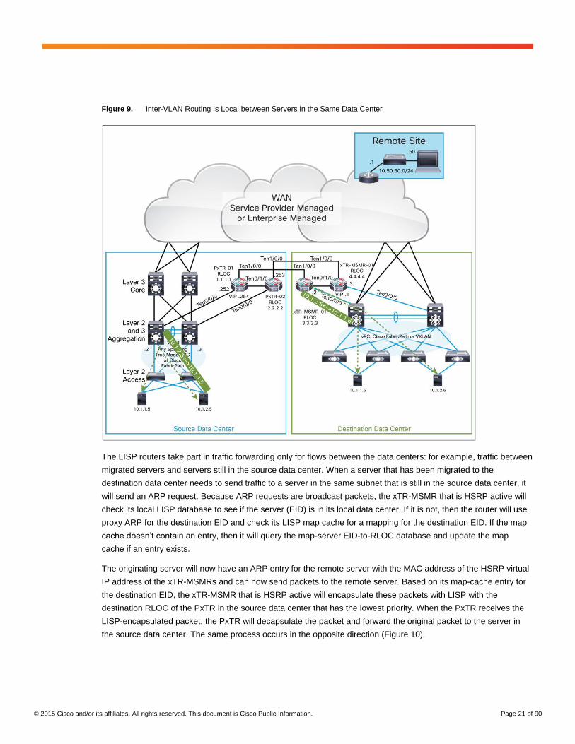
Figure 9. Inter-VLAN Routing Is Local between Servers in the Same Data Center
The LISP routers take part in traffic forwarding only for flows between the data centers: for example, traffic between
migrated servers and servers still in the source data center. When a server that has been migrated to the
destination data center needs to send traffic to a server in the same subnet that is still in the source data center, it
will send an ARP request. Because ARP requests are broadcast packets, the xTR-MSMR that is HSRP active will
check its local LISP database to see if the server (EID) is in its local data center. If it is not, then the router will use
proxy ARP for the destination EID and check its LISP map cache for a mapping for the destination EID. If the map
cache doesn’t contain an entry, then it will query the map-server EID-to-RLOC database and update the map
cache if an entry exists.
The originating server will now have an ARP entry for the remote server with the MAC address of the HSRP virtual
IP address of the xTR-MSMRs and can now send packets to the remote server. Based on its map-cache entry for
the destination EID, the xTR-MSMR that is HSRP active will encapsulate these packets with LISP with the
destination RLOC of the PxTR in the source data center that has the lowest priority. When the PxTR receives the
LISP-encapsulated packet, the PxTR will decapsulate the packet and forward the original packet to the server in
the source data center. The same process occurs in the opposite direction (Figure 10).

© 2015 Cisco and/or its affiliates. All rights reserved. This document is Cisco Public Information. Page 22 of 90
Figure 10. Intra-VLAN Traffic between Data Centers
The xTR-MSMRs will be the default gateway for servers migrated to the destination data center. So for inter-VLAN
traffic between data centers, the server in the destination data center will forward the traffic to its default gateway,
which is the HSRP virtual IP address of the xTR-MSMRs. The HSRP active xTR-MSMR will check its map cache
as in the previous example, and LISP encapsulate the packet to the source data center PxTR. The PxTR will
decapsulate the packet and forward it to the server.
In the source data center, the PxTRs are not the default gateway for the servers, so for return traffic the server in
the source data center will send the traffic to the aggregation switches, which are its default gateway. The
aggregation switches will send ARP requests for the destination, and the active PxTR will use proxy-ARP for the
server if it doesn’t have an entry for it in its local LISP database. Hence, the aggregation switches will use the
PxTR’s HSRP virtual IP MAC address when forwarding the frame to the destination server. Then the PxTR will
LISP encapsulate the packet with a destination RLOC of the xTR-MSMR with the lowest priority according to its
map cache (Figure 11).

© 2015 Cisco and/or its affiliates. All rights reserved. This document is Cisco Public Information. Page 23 of 90
Figure 11. Inter-VLAN Traffic between Data Centers
Because the source data center LISP routers are proxy ingress and egress tunnel routers (PxTRs), traffic to and
from the WAN to the servers that have been migrated will be LISP encapsulated between the two data centers.
Traffic from the WAN to a server that has been migrated to the destination data center will follow the IP route
advertised by the core switches in the source data center. This traffic will be routed to the aggregation switches,
which will send ARP requests for the destination. The PxTR that is HSRP active will use proxy-ARP for the server if
it is not in its local LISP database. Hence, the traffic will be attracted to the PxTR, which will LISP encapsulate it for
the destination data center xTR-MSMR. Because the PITR function is enabled on the PxTRs, they will not check
the source address of the packet to make sure that the source is a LISP-enabled subnet before forwarding it. This
check is performed only by an ITR.
For the traffic from the destination data center server to the WAN, the server will send the traffic to its default
gateway, which is the HSRP virtual IP address of the xTR-MSMRs. The use-PETR function is enabled on the xTR-
MSMRs. Therefore, if the xTR-MSMR receives a negative map reply for the destination address, it will LISP
encapsulate it to a preconfigured PETR, which in this case is the PxTRs. A negative map reply means that the map
server does not have any EID-to-RLOC mapping for the destination, which is expected for any destination that is
on a non-LISP site. Hence, in this case the xTR-MSMR will LISP encapsulate the packet to the PxTR with the
lowest configured priority.
© 2015 Cisco and/or its affiliates. All rights reserved. This document is Cisco Public Information. Page 24 of 90
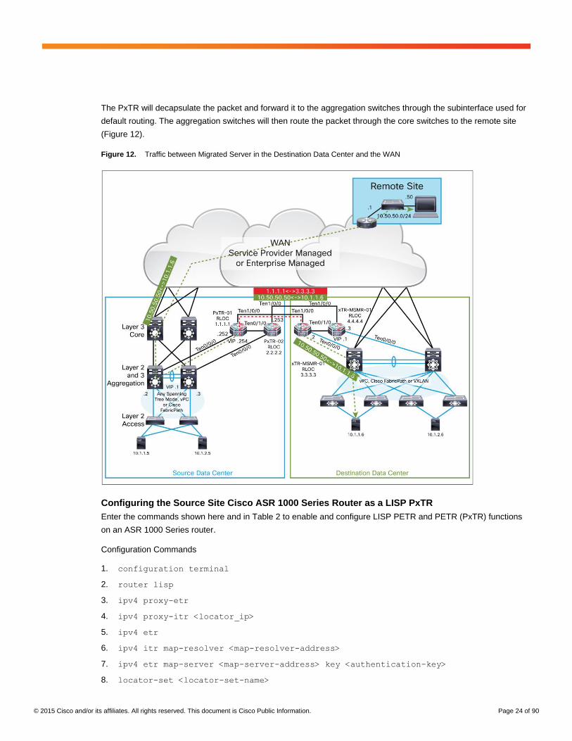
The PxTR will decapsulate the packet and forward it to the aggregation switches through the subinterface used for
default routing. The aggregation switches will then route the packet through the core switches to the remote site
(Figure 12).
Figure 12. Traffic between Migrated Server in the Destination Data Center and the WAN
Configuring the Source Site Cisco ASR 1000 Series Router as a LISP PxTR
Enter the commands shown here and in Table 2 to enable and configure LISP PETR and PETR (PxTR) functions
on an ASR 1000 Series router.
Configuration Commands
1. configuration terminal
2. router lisp
3. ipv4 proxy-etr
4. ipv4 proxy-itr <locator_ip>
5. ipv4 etr
6. ipv4 itr map-resolver <map-resolver-address>
7. ipv4 etr map-server <map-server-address> key <authentication-key>
8. locator-set <locator-set-name>
© 2015 Cisco and/or its affiliates. All rights reserved. This document is Cisco Public Information. Page 25 of 90
9. <locator_ip> priority <priority-value> weight <weight-value>
10. eid-table default instance-id 0
11. dynamic-eid <dynamic-eid-name>
12. database-mapping <dynamic-eid-prefix> locator-set <locator-set-name>
13. map-notify-group <map-notify-group-ip>
14. exit
15. interface <interface-name>
16. lisp mobility <dynamic-eid-map-name>
17. no lisp mobility liveness test
18. ip proxy-arp
19. exit
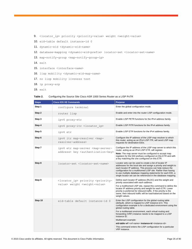
Table 2. Configuring the Source Site Cisco ASR 1000 Series Router as a LISP PxTR
Steps Cisco IOS XE Commands Purpose
Step 1 configure terminal Enter the global configuration mode.
Step 2 router lisp Enable and enter into the router LISP configuration mode.
Step 3 ipv4 proxy-etr Enable LISP PETR functions for the IPv4 address family.
Step 4 ipv4 proxy-itr <locator_ip> Enable LISP PITR functions for the IPv4 address family.
Step 5 ipv4 etr Enable LISP ETR functions for the IPv4 address family.
Step 6 ipv4 itr map-resolver <map-
resolver-address>
Configure the IP address of the LISP map resolver to which this router, acting as an IPv4 LISP ITR, will send LISP map requests for destination EIDs.
Step 7 ipv4 etr map-server <map-server-
address> key <authentication-key>
Configure the IP address of the LISP map server to which this router, acting as an IPv4 LISP ETR, will register.
Note: The map server must be configured to accept map registers for the EID prefixes configured on this ETR and with a key matching the one configured on this ETR.
Step 8 locator-set <locator-set-name> Locator sets can be used to create a list of locator IP addresses for the local site and assign a priority and weight to each locator IP address. This process can help reduce the configuration for a multihomed LISP site. Rather than having to use multiple database mapping statements for each EID, a single locator set can be referenced in the database mapping.
Step 9 <locator_ip> priority <priority-
value> weight <weight-value>
Define each locator IP address (RLOC) and the weight and priority associated with each address.
For a multihomed LISP site, repeat this command to define the locator IP address priority and weight for each ETR. Lower priority is preferred for inbound traffic. If the priority is the same, then inbound traffic will be load-balanced based on the weight values.
Step 10 eid-table default instance-id 0 Enter the LISP configuration for the global routing table (default), which is mapped to LISP instance-id 0. This configuration example is for a dedicated environment using the global routing table.
For a multitenant environment, each virtual routing and forwarding (VRF) instance needs to be mapped to a LISP instance ID.
Multitenant example:
eid-table vrf <vrf-name> instance-id <instance-id>
This command enters the LISP configuration for a particular VRF instance.

© 2015 Cisco and/or its affiliates. All rights reserved. This document is Cisco Public Information. Page 26 of 90
Steps Cisco IOS XE Commands Purpose
Step 11 dynamic-eid <dynamic-eid-map-
name>
Enter the dynamic-EID map configuration mode.
Note: The dynamic-eid-map-name entry can be any user-defined name.
Step 12 database-mapping <dynamic-eid-
prefix> locator-set <locator-set-
name>
Configure a dynamic-EID range and the RLOC mapping relationship and associated traffic policy for all IPv4 dynamic-EID prefixes for this LISP site based on the locator set previously defined.
Because this command is configured in the dynamic-EID map configuration mode, the LISP ETR will register a /32 host prefix with the mapping system after a dynamic EID is detected in the configured range.
Step 13 map-notify-group <map-notify-
group-ip>
If the LISP dynamic-EID site is multihomed, this command sends a message noting dynamic-EID detection by one ETR to the second ETR in the same site, so the traffic can be handled or load balanced by both xTRs.
In this case, enter the map-notify-group command for the dynamic-EID map with a multicast group IP address. This address is used to send a map-notify message from the ETR to all other ETRs belonging to the same LISP and data center sites after a dynamic EID is detected. This multicast group IP address can be whatever the user wants other than an address that is already in use in the network.
Step 14 exit Exit the LISP configuration mode.
Step 15 interface <interface-name> Enter the interface configuration mode.
This interface is the interface or subinterface on which LISP mobility is to be enabled. This interface or subinterface must be in the same VLAN as the servers to be migrated.
Step 16 lisp mobility <dynamic-eid-map-
name>
Enable the interface for LISP mobility, and configure the interface to allow dynamic EIDs to be detected within the prefix defined by the database mapping for the dynamic-EID map name in the LISP configuration.
The dynamic-eid-map-name entry is the dynamic EID map name configured in Step 11.
Step 17 no lisp mobility liveness test Optional. Disable the LISP liveness test, which is enabled by default when LISP mobility is enabled on an interface.
The liveness test sends a ping every 60 seconds to every dynamic EID detected, to make sure it is still reachable. This test is not required for the data center migration use case.
Step 18 ip proxy-arp Enable proxy-ARP on the interface.
Proxy-ARP is enabled by default and is required for intra-VLAN traffic to work using LISP mobility between sites.
Step 19 exit Exit the interface configuration mode.
Configuring the Destination Site Cisco ASR 1000 Series Router as a LISP xTR, Map Server, and
Map Resolver
Enter the commands shown here and in Table 3 to enable and configure LISP map-server, map-resolver, and ITR
and ETR (xTR) functions on an ASR 1000 Series router.
Configuration Commands
1. configuration terminal
2. router lisp
3. ipv4 map-server
4. ipv4 map-resolver
5. site <site-name>
6. authentication-key <authentication-key>

© 2015 Cisco and/or its affiliates. All rights reserved. This document is Cisco Public Information. Page 27 of 90
7. eid-prefix <eid‐ prefix> accept-more-specifics
8. exit
9. ipv4 itr
10. ipv4 etr
11. ipv4 use-petr <petr-locator-ip> priority <priority-value> weight <weight-value>
12. ipv4 itr map-resolver <map-resolver-address>
13. ipv4 etr map-server <map-server-address> key <authentication-key>
14. locator-set <locator-set-name>
15. <locator_ip> priority <priority-value> weight <weight-value>
16. eid-table default instance-id 0
17. dynamic-eid <dynamic-eid-name>
18. database-mapping <dynamic-eid-prefix> locator-set <locator-set-name>
19. map-notify-group <map-notify-group-ip>
20. exit
21. interface <interface-name>
22. lisp mobility <dynamic-eid-map-name>
23. no lisp mobility liveness test
24. ip proxy-arp
25. exit
Table 3. Configuring the Destination Site Cisco ASR 1000 Series Router as a LISP xTR, Map Server, and Map Resolver
Steps Cisco IOS XE Commands Purpose
Step 1 configure terminal Enter the global configuration mode.
Step 2 router lisp Enable and enter into the router LISP configuration mode.
Step 3 ipv4 map-server Enable LISP map-server functions for the IPv4 address family.
Step 4 ipv4 map-resolver Enable LISP map-resolver functions for the IPv4 address family.
Step 5 site <site-name> Create the indicated LISP site and enter the LISP site configuration mode for the map server.
Step 6 authentication-key
<authentication-key>
Enter the authentication key type and password for the LISP site being configured.
Note: The password must match the one configured on the ETR for the ETR to register successfully.
Step 7 eid-prefix <eid‐prefix> accept-more-specifics
Enter the EID prefix for which the LISP site being configured is authoritative, and configure the site to accept more specific prefixes in the event of dynamic-EID map configurations in the ETR.
Note: If the ETR is configured with a dynamic-EID map with a prefix to roam, that prefix should be configured in the map server using this command.
If the EID prefixes configured on the ETRs are contiguous, then a single larger prefix that covers all the smaller prefixes can be defined here to reduce the configuration size.
Note: This example applies only to the global routing table. When using LISP for multiple VRF instances, the instance ID needs to be defined with the eid-prefix command.

© 2015 Cisco and/or its affiliates. All rights reserved. This document is Cisco Public Information. Page 28 of 90
Steps Cisco IOS XE Commands Purpose
Step 8 exit Exit the LISP site configuration mode.
Step 9 ipv4 itr Enable LISP ITR functions for the IPv4 address family.
Step 10 ipv4 etr Enable LISP ETR functions for the IPv4 address family.
Step 11 ipv4 use-petr <petr-locator-ip>
priority <priority-value> weight
<weight-value>
Optional. If symmetric routing of traffic back to the source data center is required from servers that have migrated to remote non-LISP enabled sites, then the use-PETR function can be used. When there is a negative map reply for a destination IP, then traffic to that destination will be LISP encapsulated to the PETR.
If there are multiple PETRs, then repeat this command to define the locator IP address and priority and weight for each PETR.
Step 12 ipv4 itr map-resolver <map-
resolver-address>
Configure the IP address of the LISP map resolver to which this router, acting as an IPv4 LISP ITR, will send LISP map requests for destination EIDs.
Step 13 ipv4 etr map-server <map-server-
address> key <authentication-key>
Configure the IP address of the LISP map server to which this router, acting as an IPv4 LISP ETR, will register.
Note: The map server must be configured to accept map registers for the EID prefixes configured on this ETR and with a key matching the one configured on this ETR.
Step 14 locator-set <locator-set-name> Locator sets can be used to create a list of locator IP addresses for the local site and assign a priority and weight to each locator IP address. This process can help reduce the configuration for a multihomed LISP site. Rather than having to use multiple database mapping statements for each EID, a single locator set can be referenced in the database mapping.
Step 15 <locator_ip> priority <priority-
value> weight <weight-value>
Define each locator IP address (RLOC) and the weight and priority associated with each address.
For a multihomed LISP site, repeat this command to define the locator IP address and priority and weight for each ETR. Lower priority is preferred for inbound traffic. If the priority is the same, then inbound traffic will be load-balanced based on the weight values.
Step 16 eid-table default instance-id 0 Enter the LISP configuration for the global routing table (default), which is mapped to LISP instance-id 0.
This configuration example is for a dedicated environment using the global routing table.
For a multitenant environment, each VRF instance needs to be mapped to a LISP instance ID.
Multitenant example:
eid-table vrf <vrf-name> instance-id <instance-id>
This command enters the LISP configuration for a particular VRF instance.
Step 17 dynamic-eid <dynamic-eid-map-
name>
Enter the dynamic-EID map configuration mode.
Note: The dynamic-eid-map-name entry can be any user-defined name.
Step 18 database-mapping <dynamic-eid-
prefix> locator-set <locator-set-
name>
Configure a dynamic-EID range and the RLOC mapping relationship and associated traffic policy for all IPv4 dynamic-EID prefixes for this LISP site based on the locator set previously defined.
Because this command is configured in the dynamic-EID map configuration mode, the LISP ETR will register a /32 host prefix with the mapping system after a dynamic EID is detected in the configured range.

© 2015 Cisco and/or its affiliates. All rights reserved. This document is Cisco Public Information. Page 29 of 90
Steps Cisco IOS XE Commands Purpose
Step 19 map-notify-group <map-notify-
group-ip>
If the LISP dynamic-EID site is multihomed, this command sends a message noting dynamic-EID detection by one ETR to the second ETR in the same site, so the traffic can be handled or load-balanced by both xTRs.
In this case, enter the map-notify-group command for the dynamic-EID map with a multicast group IP address. This address is used to send a map-notify message from the ETR to all other ETRs belonging to the same LISP and data center sites after a dynamic EID is detected. This multicast group IP address can be whatever the user wants other than an address that is already in use in the network.
Step 20 exit Exit the LISP configuration mode.
Step 21 interface <interface-name> Enter the interface configuration mode.
This interface is the interface or subinterface on which LISP mobility is to be enabled. This interface or subinterface must be in the VLAN to which the servers are being migrated.
Step 22 lisp mobility <dynamic-eid-map-
name>
Enable the interface for LISP mobility, and configure the interface to allow dynamic EIDs to be detected within the prefix defined by the database mapping for the dynamic-EID map name in the LISP configuration.
The dynamic-eid-map-name entry is the dynamic EID map name configured in step 17.
Step 23 no lisp mobility liveness test Optional. Disable the LISP liveness test, which is enabled by default when LISP mobility is enabled on an interface.
The liveness test sends a ping every 60 seconds to every dynamic EID detected, to make sure it is still reachable. This test is not required for the data center migration use case.
Step 24 ip proxy-arp Enable proxy-ARP on the interface.
Proxy-ARP is enabled by default and is required for intra-VLAN traffic to work using LISP mobility between sites.
Step 25 exit Exit the interface configuration mode.
Multicast Configuration for LISP Map-Notify Messages in a Multihomed Environment
The ASR 1000 Series routers do not support multicast host mode. Therefore, multicast routing need to be enabled
to allow the site-local multicast LISP map-notify message to be processed. This configuration is required only for a
multihomed site to keep the LISP databases synchronized between the two xTRs at the site. Enter the commands
shown here and in Table 4 to enable multihoming an ASR 1000 Series router.
Configuration Commands
1. configuration terminal
2. ip multicast-routing
3. interface Loopback <number>
4. ip address <loopback-ip-address> <subnet-mask>
5. ip pim sparse-mode
6. ip pim rp-address <loopback-ip-address>
7. interface <interface-name>
8. ip pim sparse-mode
9. exit

© 2015 Cisco and/or its affiliates. All rights reserved. This document is Cisco Public Information. Page 30 of 90
Table 4. Multicast Configuration for LISP Map-Notify Messages in a Multihomed Environment
Steps Cisco IOS XE Commands Purpose
Step 1 configure terminal Enter the global configuration mode.
Step 2 ip multicast-routing Enable multicast routing for the global routing table.
Step 3 interface Loopback <number> Create a new loopback interface to be used as the Protocol-Independent Multicast (PIM) rendezvous point (RP).
Step 4 ip address <loopback-ip-address>
<subnet-mask>
Configure the loopback interface with an IP address not already in use.
Step 5 ip pim sparse-mode Enable PIM sparse mode on the loopback interface.
Step 6 ip pim rp-address <loopback-ip-
address>
Statically configure the router to use its only loopback interface address, defined in step 4, as its PIM RP.
Step 7 interface <interface-name> Enter the interface configuration for the interfaces or subinterfaces that have been configured for LISP mobility. These are the internal interfaces on the server VLANs.
Step 8 ip pim sparse-mode Enable PIM sparse mode for the interfaces that have LISP mobility enabled.
Step 9 exit Exit interface configuration mode.
Configuration Examples
The following configuration examples show the full ASR 1000 Series router configuration for the sample
multihomed data center migration topology. The examples enable LISP mobility on two subnets, 10.1.1.0/24 and
10.1.2.0/24, so servers within those subnets can be migrated from the source to the destination data center.
Source Data Center Cisco ASR 1000 Routers
PxTR-01 Comments
hostname PxTR-01
!
ip multicast-routing
!
ip cef
!
track timer interface msec 500
track timer ip route msec 500
!
track 1 interface
TegGigabitEthernet0/0/0 line-protocol
delay up 180
!
track 2 ip route 3.3.3.3
255.255.255.255 reachability
delay up 180
!
Multicast routing is enabled for LISP site-local map-notify messages.
Tracking timers are reduced for faster detection of failures.
Tracking object 1 tracks the line protocol of the internal interface facing the aggregation switch.
Tracking objects 2 and 3 track the route for the xTR-MSMR’s RLOC addresses.
Tracking object 4 is a Boolean OR of objects 2 and 3. Therefore, object 4 will go down only if both object 2 and object 3 are down: that is, if PxTR-01 loses its route to both xTR-MSMRs.
Loopback 0 is the RLOC.
Loopback 1 is the PIM RP.
Interface Ten0/0/0 connects to the aggregation switch in the source data center.
Ten0/0/0.200 is the subinterface for VLAN 200 server subnet 10.1.1.0/24. LISP mobility is enabled for this subnet.

© 2015 Cisco and/or its affiliates. All rights reserved. This document is Cisco Public Information. Page 31 of 90
PxTR-01 Comments
track 3 ip route 4.4.4.4
255.255.255.255 reachability
delay up 180
!
track 4 list boolean or
object 2
object 3
!
interface Loopback0
ip address 1.1.1.1 255.255.255.255
ip ospf 1 area 0
!
interface Loopback1
ip address 11.11.11.11 255.255.255.255
ip pim sparse-mode
!
interface LISP0
!
interface TegGigabitEthernet0/0/0
no ip address
!
interface TegGigabitEthernet0/0/0.200
encapsulation dot1Q 200
ip address 10.1.1.252 255.255.255.0
ip pim sparse-mode
standby delay minimum 180 reload 300
standby 100 ip 10.1.1.254
standby 100 timers 1 3
standby 100 priority 105
standby 100 preempt
standby 100 track 4 decrement 10
no lisp mobility liveness test
lisp mobility LISP-SUBNET-A
!
interface TegGigabitEthernet0/0/0.201
encapsulation dot1Q 201
ip address 10.1.2.252 255.255.255.0
ip pim sparse-mode
standby delay minimum 180 reload 300
For all subinterfaces with LISP mobility enabled, PxTR-01 is given a higher HSRP priority than PxTR-2. So PxTR-01 will be HSRP active during normal conditions.
HSRP on all LISP enabled subinterfaces on PxTR-01 tracks object 4. Therefore, if PxTR-01 loses its routes to both xTR-MSMRs, then PxTR-01 will become HSRP standby, and PxTR-02 will become HSRP active.
Ten0/0/0.201 is the subinterface for VLAN 201 server subnet 10.1.2.0/24. LISP mobility is enabled for this subnet.
Ten0/0/0.500 is the subinterface for used for default-gateway routing to the aggregation-layer switches in the source data center. LISP is not enabled on this subinterface.
Ten0/1/0 is the link to PxTR-02.
OSPF and BFD are enabled on the links between the LISP routers.
Ten1/0/0 is the link to xTR-MSMR-01.
In the LISP configuration. a locator set is used to specify the RLOCs for the source data center: that is, the RLOCs of PxTR-01 and PxTR-02. A lower priority is used for PxTR-01, so incoming LISP traffic will be directed to PxTR-01 during normal circumstances.
LISP instance-id 0 is used because all LISP enabled subnets are in the global routing table.
The two server subnets for LISP mobility are defined and mapped to the locator set defined above.
A unique multicast group is used for each LISP mobility subnet for the site-local LISP map-notify messages.
The PxTRs are enabled as proxy ingress and egress tunnel routers.
The map servers and map resolvers are defined as the LISP routers in the destination data centers xTR-MSMR-01 and xTR-MSMR-02.
OSPF is used to advertise the RLOC addresses (loopback 0) to the other LISP routers.
Each LISP router is statically configured with itself (loopback 1) as the PIM RP. This configuration is required for the site-local LISP map-notify messages
The static default route is defined with the aggregation switches in the source data center as the next hop out subinterface Ten0/0/0.500.
An EEM script is used to shut down the RLOC interface loopback 0 on PxTR-01 if the interface Ten0/0/0 facing the aggregation switch goes down (tracked object 1 defined above). This configuration is required so that the xTR-MSMRs will see the RLOC of PxTR-01 go down, and so they won’t forward LISP traffic to it during this failure scenario. This setting will force the incoming LISP traffic over to PxTR-02.
Another EEM script is used to bring the RLOC interface loopback 0 on PxTR-01 back up after the interface Ten0/0/0 facing the aggregation switch comes back up.
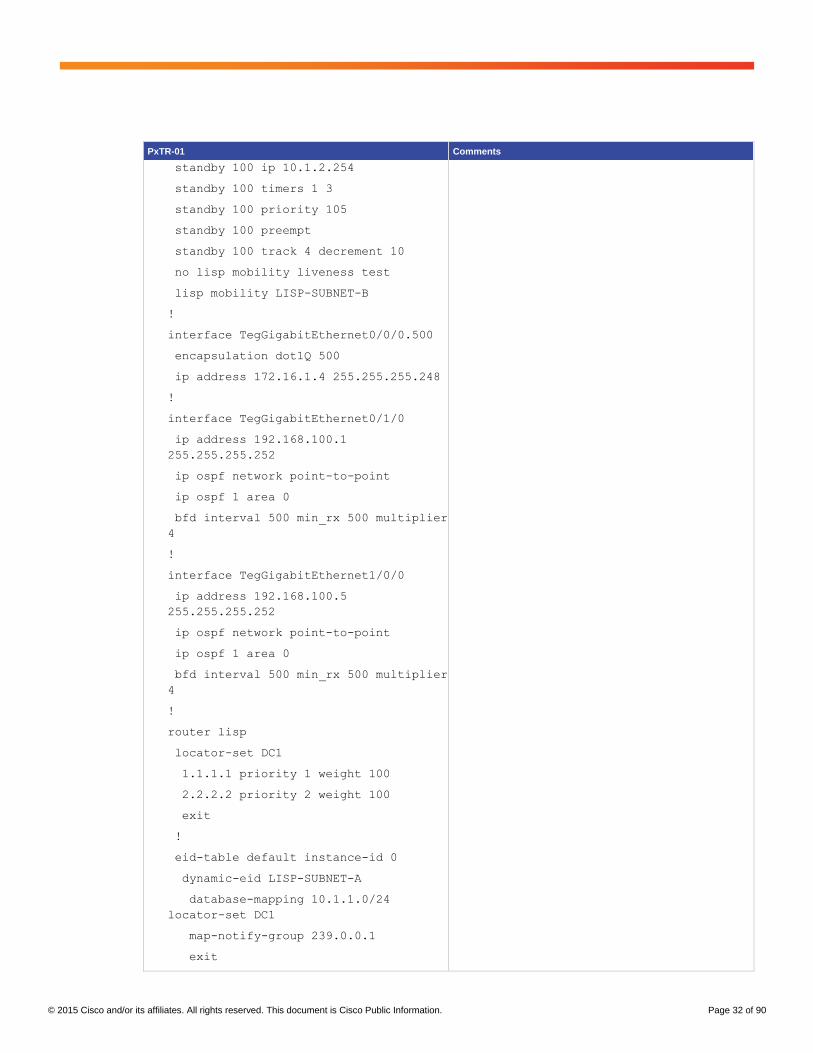
© 2015 Cisco and/or its affiliates. All rights reserved. This document is Cisco Public Information. Page 32 of 90
PxTR-01 Comments
standby 100 ip 10.1.2.254
standby 100 timers 1 3
standby 100 priority 105
standby 100 preempt
standby 100 track 4 decrement 10
no lisp mobility liveness test
lisp mobility LISP-SUBNET-B
!
interface TegGigabitEthernet0/0/0.500
encapsulation dot1Q 500
ip address 172.16.1.4 255.255.255.248
!
interface TegGigabitEthernet0/1/0
ip address 192.168.100.1
255.255.255.252
ip ospf network point-to-point
ip ospf 1 area 0
bfd interval 500 min_rx 500 multiplier
4
!
interface TegGigabitEthernet1/0/0
ip address 192.168.100.5
255.255.255.252
ip ospf network point-to-point
ip ospf 1 area 0
bfd interval 500 min_rx 500 multiplier
4
!
router lisp
locator-set DC1
1.1.1.1 priority 1 weight 100
2.2.2.2 priority 2 weight 100
exit
!
eid-table default instance-id 0
dynamic-eid LISP-SUBNET-A
database-mapping 10.1.1.0/24
locator-set DC1
map-notify-group 239.0.0.1
exit

© 2015 Cisco and/or its affiliates. All rights reserved. This document is Cisco Public Information. Page 33 of 90
PxTR-01 Comments
!
dynamic-eid LISP-SUBNET-B
database-mapping 10.1.2.0/24
locator-set DC1
map-notify-group 239.0.0.2
exit
!
exit
!
ipv4 locator reachability exclude-
default
ipv4 map-cache-limit 5000
ipv4 proxy-etr
ipv4 proxy-itr 1.1.1.1
ipv4 itr map-resolver 3.3.3.3
ipv4 itr map-resolver 4.4.4.4
ipv4 etr map-server 3.3.3.3 key
CISCO123
ipv4 etr map-server 4.4.4.4 key
CISCO123
ipv4 etr
exit
!
router ospf 1
router-id 1.1.1.1
auto-cost reference-bandwidth 100000
timers throttle spf 10 100 5000
timers throttle lsa 10 100 5000
timers lsa arrival 90
bfd all-interfaces
!
ip pim rp-address 11.11.11.11
!
ip route 0.0.0.0 0.0.0.0 172.16.1.1
!
!
event manager applet INTERNAL-
INTERFACE-IS-DOWN
event track 1 state down
action 1.0 cli command "enable"

© 2015 Cisco and/or its affiliates. All rights reserved. This document is Cisco Public Information. Page 34 of 90
PxTR-01 Comments
action 1.1 cli command "conf t"
action 2.0 cli command "interface
loop0"
action 3.0 cli command "shut"
action 9.0 syslog msg "INTERNAL
INTERFACE DOWN, RLOC 1.1.1.1 HAS BEEN
SHUTDOWN"
!
event manager applet INTERNAL-
INTERFACE-IS-UP
event track 1 state up
action 1.0 cli command "enable"
action 1.1 cli command "config t"
action 2.0 cli command "interface
loop0"
action 3.0 cli command "no shut"
action 9.0 syslog msg "INTERNAL
INTERFACE UP, RLOC 1.1.1.1 HAS BEEN
RESTORED"
!
end
PxTR-02 Comments
hostname PxTR-02
!
ip multicast-routing
!
ip cef
!
interface Loopback0
ip address 2.2.2.2 255.255.255.255
ip ospf 1 area 0
!
interface Loopback1
ip address 22.22.22.22 255.255.255.255
ip pim sparse-mode
!
interface LISP0
!
interface TegGigabitEthernet0/0/0
Multicast routing is enabled for LISP site-local map-notify messages.
Loopback 0 is the RLOC.
Loopback 1 is the PIM RP.
Interface Ten0/0/0 connects to the aggregation switch in the source data center.
Ten0/0/0.200 is the subinterface for VLAN 200 server subnet 10.1.1.0/24. LISP mobility is enabled for this subnet.
For all subinterfaces with LISP mobility enabled, PxTR-01 is given a higher HSRP priority than PxTR-2. So PxTR-01 will be HSRP active during normal conditions.
Ten0/0/0.201 is the subinterface for VLAN 201 server subnet 10.1.2.0/24. LISP mobility is enabled for this subnet.
Ten0/0/0.500 is the subinterface used for default-gateway routing to the aggregation-layer switches in the source data center. LISP is not enabled on this subinterface.
Ten0/1/0 is the link to PxTR-01.

© 2015 Cisco and/or its affiliates. All rights reserved. This document is Cisco Public Information. Page 35 of 90
PxTR-02 Comments
no ip address
!
interface TegGigabitEthernet0/0/0.200
encapsulation dot1Q 200
ip address 10.1.1.253 255.255.255.0
ip pim sparse-mode
standby 100 ip 10.1.1.254
standby 100 timers 1 3
standby 100 preempt
no lisp mobility liveness test
lisp mobility LISP-SUBNET-A
!
interface TegGigabitEthernet0/0/0.201
encapsulation dot1Q 201
ip address 10.1.2.253 255.255.255.0
ip pim sparse-mode
standby 100 ip 10.1.2.254
standby 100 timers 1 3
standby 100 preempt
no lisp mobility liveness test
lisp mobility LISP-SUBNET-B
!
interface TegGigabitEthernet0/0/0.500
encapsulation dot1Q 500
ip address 172.16.1.5 255.255.255.248
!
interface TegGigabitEthernet0/1/0
ip address 192.168.100.2 255.255.255.252
ip ospf network point-to-point
ip ospf 1 area 0
bfd interval 500 min_rx 500 multiplier 4
!
interface TegGigabitEthernet1/0/0
ip address 192.168.100.9 255.255.255.252
ip ospf network point-to-point
ip ospf 1 area 0
bfd interval 500 min_rx 500 multiplier 4
!
router lisp
OSPF and BFD are enabled on the links between the LISP routers.
Ten1/0/0 is the link to xTR-MSMR-02.
In the LISP configuration, a locator set is used to specify the RLOCs for the source data center: that is, the RLOCs of PxTR-01 and PxTR-02. A lower priority is used for PxTR-01, so incoming LISP traffic will be directed to PxTR-01 during normal circumstances.
LISP instance-id 0 is used because all LISP enabled subnets are in the global routing table.
The two server subnets for LISP mobility are defined and mapped to the locator set defined above.
A unique multicast group is used for each LISP mobility subnet for the site-local LISP map-notify messages.
The PxTRs are enabled as proxy ingress and egress tunnel routers.
The map servers and map resolvers are defined as the LISP routers in the destination data centers xTR-MSMR-01 and xTR-MSMR-02.
OSPF is used to advertise the RLOC addresses (loopback 0) to the other LISP routers.
Each LISP router is statically configured with itself (loopback 1) as the PIM RP. This configuration is required for the site-local LISP map-notify messages.
The static default route is defined with the aggregation switches in the source data center as the next hop out subinterface Ten0/0/0.500.

© 2015 Cisco and/or its affiliates. All rights reserved. This document is Cisco Public Information. Page 36 of 90
PxTR-02 Comments
locator-set DC1
1.1.1.1 priority 1 weight 100
2.2.2.2 priority 2 weight 100
exit
!
eid-table default instance-id 0
dynamic-eid LISP-SUBNET-A
database-mapping 10.1.1.0/24 locator-set
DC1
map-notify-group 239.0.0.1
exit
!
dynamic-eid LISP-SUBNET-B
database-mapping 10.1.2.0/24 locator-set
DC1
map-notify-group 239.0.0.2
exit
!
exit
!
ipv4 locator reachability exclude-default
ipv4 map-cache-limit 5000
ipv4 proxy-etr
ipv4 proxy-itr 2.2.2.2
ipv4 itr map-resolver 3.3.3.3
ipv4 itr map-resolver 4.4.4.4
ipv4 etr map-server 3.3.3.3 key CISCO123
ipv4 etr map-server 4.4.4.4 key CISCO123
ipv4 etr
exit
!
router ospf 1
router-id 2.2.2.2
auto-cost reference-bandwidth 100000
timers throttle spf 10 100 5000
timers throttle lsa 10 100 5000
timers lsa arrival 90
bfd all-interfaces
!

© 2015 Cisco and/or its affiliates. All rights reserved. This document is Cisco Public Information. Page 37 of 90
PxTR-02 Comments
ip pim rp-address 22.22.22.22
!
ip route 0.0.0.0 0.0.0.0 172.16.1.1
!
end
Detecting EIDs with EEM Scripts
Because the PxTRs are not the default gateway in the source data center, they depend on receipt of broadcasts
such as ARP requests from servers to detect servers and add them to their local LISP database as dynamic EIDs.
To make sure the PxTRs learn about servers that may not be sending broadcast ARP requests within the LISP-
enabled subnets, the following EEM scripts can be used to generate a unicast ping to each IP address in the
subnets. Before each ping is sent, the PxTR will send an ARP request to resolve the MAC address that
corresponds to the IP address. After the server replies to the ARP request, the PxTR will detect it and add it to its
LISP database as a dynamic EID. Because only the ARP reply is needed, it does not matter if the server blocks the
ICMP ping.
Note that these scripts are required only on the primary PxTR in the source data center. After the primary PxTR
learns about the dynamic EIDs, it will update the secondary PxTR using the LISP multicast map-notify message.
The scripts that follow can be run manually using the command-line interface (CLI).
EEM Applet to Ping All IP Addresses in Multiple /24 Subnets Comments
event manager applet SUBNET -PING-SLASH24
event cli pattern sweep24 enter maxrun 3600 ratelimit
60
action 001 cli command "enable"
action 002 foreach _NETWORK "10.1.1 10.1.2 10.1.3"
action 003 set HOST 1
action 004 while $HOST lt 255
action 005 cli command "ping $_NETWORK.$HOST repeat
1 timeout 0"
action 006 syslog priority debugging msg
"$_cli_result"
action 007 increment HOST
action 008 end
action 009 end
action 010 syslog msg "SUBNET PING COMPLETE"
This EEM applet can be run by typing the command sweep24 in execution mode. It will ping all IP addresses in three /24 subnets: 10.1.1.0/24, 10.1.2.0/24, and 10.1.3.0/24. If the logging level is set to 7 (debugging), then the results of each ping will be displayed.

© 2015 Cisco and/or its affiliates. All rights reserved. This document is Cisco Public Information. Page 38 of 90
EEM Applet to Ping All IP Addresses in Multiple /16 Subnets Comments
event manager applet SUBNET -PING-SLASH16
event cli pattern sweep16 enter maxrun 172800
ratelimit 60
action 001 cli command "enable"
action 002 foreach _NETWORK "10.2 172.16 192.168"
action 003 set 3OCT 0
action 004 while $3OCT lt 255
action 005 set 4OCT 1
action 006 while $4OCT lt 255
action 007 cli command "ping $_NETWORK.$3OCT.$4OCT
repeat 1 timeout 0"
action 008 syslog priority debugging msg
"$_cli_result"
action 009 increment 4OCT
action 010 end
action 011 increment 3OCT
action 012 end
action 013 end
action 014 syslog msg "SUBNET PING COMPLETE"
This EEM applet can be run by typing the command sweep16 in execution mode. It will ping all IP addresses in three /16 subnets: 10.2.0.0/16, 172.16.0.0/16, and 192.168.0.0/16. If the logging level is set to 7 (debugging), then the results of each ping will be displayed.
You can also automatically run the EEM scripts whenever the physical interface on the PxTR facing the data center
aggregation switches comes up. An automatic script is useful in a single-homed deployment in which the data
center contains only a single xTR. With a single xTR, the use of an automatic script to detect dynamic EIDs can
speed up convergence if the xTR is reloaded or if it loses its connection to the aggregation switches. Without an
automatic script, the xTR would have to wait until it receives a packet from the servers before it can detect them
and add them to its local LISP database as dynamic EIDs.
For a multihomed environment with two xTRs in each data center, if either of the xTRs is reloaded or loses its
connection to the aggregation switches, upon convergence it will learn about the dynamic EIDs through the LISP
multicast map-notify message from the other xTR. So a script to detect dynamic EIDs in a multihomed environment
is needed only when the xTRs are initially added to the network.
The following example is an EEM script to detect dynamic EIDs for three /24 subnets automatically when the
interface facing the aggregation switches comes up.
EEM Applet to Ping All IP Addresses in multiple /24 Subnets Comments
track 1 interface TegGigabitEthernet0/0/0 line-protocol
delay up 60
!
event manager applet AUTOMATIC-SUBNET -PING-SLASH24
event track 1 state up maxrun 3600
action 001 cli command "enable"
action 002 foreach _NETWORK "10.1.1 10.1.2 10.1.3"
This EEM applet will run automatically 60 seconds after interface Ten0/0/0 facing the aggregation switch comes up. It will ping all IP addresses in three /24 subnets: 10.1.1.0/24, 10.1.2.0/24, and 10.1.3.0/24. If the logging level is set to 7 (debugging), then the results of each ping will be displayed.

© 2015 Cisco and/or its affiliates. All rights reserved. This document is Cisco Public Information. Page 39 of 90
EEM Applet to Ping All IP Addresses in multiple /24 Subnets Comments
action 003 set HOST 1
action 004 while $HOST lt 255
action 005 cli command "ping $_NETWORK.$HOST repeat
1 timeout 0"
action 006 syslog priority debugging msg
"$_cli_result"
action 007 increment HOST
action 008 end
action 009 end
action 010 syslog msg "SUBNET PING COMPLETE"
Destination Data Center Cisco ASR 1000 Routers
xTR-MSMR-01 Comments
hostname xTR-MSMR-01
!
ip multicast-routing
!
ip cef
!
track timer interface msec 500
track timer ip route msec 500
!
track 1 interface TegGigabitEthernet0/0/0 line-protocol
delay up 180
!
track 2 ip route 1.1.1.1 255.255.255.255 reachability
delay up 180
!
track 3 ip route 2.2.2.2 255.255.255.255 reachability
delay up 180
!
track 4 list boolean or
object 2
object 3
!
interface Loopback0
ip address 3.3.3.3 255.255.255.255
ip ospf 1 area 0
!
interface Loopback1
Multicast routing is enabled for LISP site-local map-notify messages.
Tracking timer values are reduced for faster detection of failures.
Tracking object 1 tracks the line protocol of the internal interface facing the aggregation switch.
Tracking object 2 and 3 track the route for the PxTR’s RLOC addresses.
Tracking object 4 is a Boolean OR of object 2 and 3. Therefore, object 4 will go down only if both object 2 and object 3 are down: that is, if xTR-MSMR-01 loses its routes to both PxTRs.
Loopback 0 is the RLOC.
Loopback 1 is the PIM RP.
Interface Ten0/0/0 connects to the spine switch in the destination data center.
Ten0/0/0.4000 is the subinterface for VLAN 4000 server subnet 10.1.1.0/24. LISP mobility is enabled for this subnet.
For all subinterfaces with LISP mobility enabled, xTR-MSMR-01 is given a higher HSRP priority than xTR-MSMR-2. So xTR-MSMR-01 will be HSRP active during normal conditions.
HSRP on all LISP-enabled subinterfaces on xTR-MSMR-01 tracks object 4. Therefore, if xTR-MSMR-01 loses its routes to both PxTRs, then xTR-MSMR-01 will become HSRP standby, and xTR-MSMR-02 will become HSRP active.

© 2015 Cisco and/or its affiliates. All rights reserved. This document is Cisco Public Information. Page 40 of 90
xTR-MSMR-01 Comments
ip address 33.33.33.33 255.255.255.255
ip pim sparse-mode
!
interface LISP0
!
interface TegGigabitEthernet0/0/0
no ip address
!
interface TegGigabitEthernet0/0/0.4000
encapsulation dot1Q 4000
ip address 10.1.1.2 255.255.255.0
ip pim sparse-mode
standby delay minimum 180 reload 300
standby 1 ip 10.1.1.1
standby 1 timers 1 3
standby 1 priority 105
standby 1 preempt
standby 1 track 4 decrement 10
no lisp mobility liveness test
lisp mobility LISP-SUBNET-A
!
interface TegGigabitEthernet0/0/0.4001
encapsulation dot1Q 4001
ip address 10.1.2.2 255.255.255.0
ip pim sparse-mode
standby delay minimum 180 reload 300
standby 1 ip 10.1.2.1
standby 1 timers 1 3
standby 1 priority 105
standby 1 preempt
standby 1 track 4 decrement 10
no lisp mobility liveness test
lisp mobility LISP-SUBNET-B
!
interface TegGigabitEthernet0/1/0
ip address 192.168.100.13 255.255.255.252
ip ospf network point-to-point
ip ospf 1 area 0
bfd interval 500 min_rx 500 multiplier 4
Ten0/0/0.4001 is the subinterface for VLAN 4001 server subnet 10.1.2.0/24. LISP mobility is enabled for this subnet.
Ten0/1/0 is the link to xTR-MSMR-02.
OSPF and BFD are enabled on the links between the LISP routers.
Ten1/0/0 is the link to PxTR-01.
In the LISP configuration, a locator set is used to specify the RLOCs for the destination data center: that is, the RLOCs of xTR-MSMR-01 and xTR-MSMR-02. A lower priority is used for xTR-MSMR-01, so incoming LISP traffic will be directed to xTR-MSMR-1 during normal circumstances.
LISP instance-id 0 is used because all LISP-enabled subnets are in the global routing table.
The two server subnets for LISP mobility are defined and mapped to the locator set defined above.
A unique multicast group is used for each LISP mobility subnet for the site-local LISP map-notify messages.
The LISP site configuration defines the authentication key and the prefixes for with the map server will accept map registers.
Both xTR-MSMRs are configured as map servers and map resolvers and to use themselves as map servers and map resolvers
OSPF is used to advertise the RLOC addresses (loopback 0) to the other LISP routers.
Each LISP router is statically configured with itself (loopback 1) as the PIM RP. This configuration is required for the site-local LISP map-notify messages.
An EEM script is used to shut down the RLOC interface loopback 0 on xTR-MSMR-01 if the interface Ten0/0/0 facing the spine switch goes down (tracked object 1 defined above). This configuration is required so that the PxTRs will see the RLOC of xTR-MSMR-01 go down, and so they won’t forward LISP traffic to it during this failure scenario. This setting will force the incoming LISP traffic over to xTR-MSMR-02.
Another EEM script is used to bring the RLOC interface loopback 0 on xTR-MSMR-01 back up after the interface Ten0/0/0 facing the spine switch comes back up.

© 2015 Cisco and/or its affiliates. All rights reserved. This document is Cisco Public Information. Page 41 of 90
xTR-MSMR-01 Comments
!
interface TegGigabitEthernet1/0/0
ip address 192.168.100.6 255.255.255.252
ip ospf network point-to-point
ip ospf 1 area 0
bfd interval 500 min_rx 500 multiplier 4
!
router lisp
locator-set DC2
3.3.3.3 priority 1 weight 100
4.4.4.4 priority 2 weight 100
exit
!
eid-table default instance-id 0
dynamic-eid LISP-SUBNET-A
database-mapping 10.1.1.0/24 locator-set DC2
map-notify-group 239.0.0.1
exit
!
dynamic-eid LISP-SUBNET-B
database-mapping 10.1.2.0/24 locator-set DC1
map-notify-group 239.0.0.2
exit
!
exit
!
site DC-MIGRATION
authentication-key CISCO123
eid-prefix 10.1.0.0/16 accept-more-specifics
exit
!
ipv4 locator reachability exclude-default
ipv4 map-server
ipv4 map-resolver
ipv4 use-petr 1.1.1.1 priority 1 weight 100
ipv4 use-petr 2.2.2.2 priority 2 weight 100
ipv4 map-cache-limit 5000
ipv4 itr map-resolver 3.3.3.3
ipv4 itr map-resolver 4.4.4.4
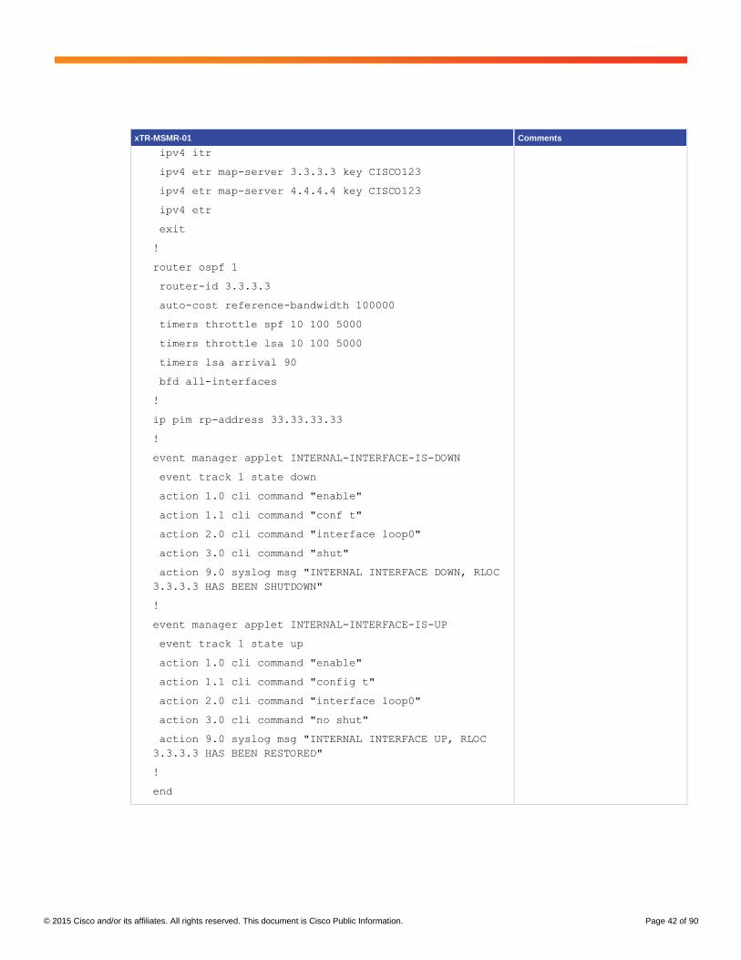
© 2015 Cisco and/or its affiliates. All rights reserved. This document is Cisco Public Information. Page 42 of 90
xTR-MSMR-01 Comments
ipv4 itr
ipv4 etr map-server 3.3.3.3 key CISCO123
ipv4 etr map-server 4.4.4.4 key CISCO123
ipv4 etr
exit
!
router ospf 1
router-id 3.3.3.3
auto-cost reference-bandwidth 100000
timers throttle spf 10 100 5000
timers throttle lsa 10 100 5000
timers lsa arrival 90
bfd all-interfaces
!
ip pim rp-address 33.33.33.33
!
event manager applet INTERNAL-INTERFACE-IS-DOWN
event track 1 state down
action 1.0 cli command "enable"
action 1.1 cli command "conf t"
action 2.0 cli command "interface loop0"
action 3.0 cli command "shut"
action 9.0 syslog msg "INTERNAL INTERFACE DOWN, RLOC
3.3.3.3 HAS BEEN SHUTDOWN"
!
event manager applet INTERNAL-INTERFACE-IS-UP
event track 1 state up
action 1.0 cli command "enable"
action 1.1 cli command "config t"
action 2.0 cli command "interface loop0"
action 3.0 cli command "no shut"
action 9.0 syslog msg "INTERNAL INTERFACE UP, RLOC
3.3.3.3 HAS BEEN RESTORED"
!
end

© 2015 Cisco and/or its affiliates. All rights reserved. This document is Cisco Public Information. Page 43 of 90
xTR-MSMR-02 Comments
hostname xTR-MSMR-02
!
ip multicast-routing
!
ip cef
!
interface Loopback0
ip address 4.4.4.4 255.255.255.255
ip ospf 1 area 0
!
interface Loopback1
ip address 44.44.44.44 255.255.255.255
ip pim sparse-mode
!
interface LISP0
!
interface TegGigabitEthernet0/0/0
no ip address
!
interface TegGigabitEthernet0/0/0.4000
encapsulation dot1Q 4000
ip address 10.1.1.3 255.255.255.0
ip pim sparse-mode
standby 1 ip 10.1.1.1
standby 1 timers 1 3
standby 1 preempt
no lisp mobility liveness test
lisp mobility LISP-SUBNET-A
!
interface TegGigabitEthernet0/0/0.4001
encapsulation dot1Q 4001
ip address 10.1.2.3 255.255.255.0
ip pim sparse-mode
standby 1 ip 10.1.2.1
standby 1 timers 1 3
standby 1 preempt
no lisp mobility liveness test
lisp mobility LISP-SUBNET-B
!
Multicast routing is enabled for LISP site-local map-notify messages.
Loopback 0 is the RLOC.
Loopback 1 is the PIM RP.
Interface Ten0/0/0 connects to the spine switch in the destination data center.
Ten0/0/0.4000 is the subinterface for VLAN 4000 server subnet 10.1.1.0/24. LISP mobility is enabled for this subnet.
For all subinterfaces with LISP mobility enabled, xTR-MSMR-01 is given a higher HSRP priority than xTR-MSMR-2. So xTR-MSMR-01 will be HSRP active during normal conditions.
Ten0/0/0.4001 is the subinterface for VLAN 4001 server subnet 10.1.2.0/24. LISP mobility is enabled for this subnet.
Ten0/1/0 is the link to xTR-MSMR-01.
OSPF and BFD are enabled on the links between the LISP routers.
Ten1/0/0 is the link to PxTR-02.
In the LISP configuration, a locator set is used to specify the RLOCs for the destination data center: that is, the RLOCs of xTR-MSMR-01 and xTR-MSMR-02. A lower priority is used for xTR-MSMR-01, so incoming LISP traffic will be directed to xTR-MSMR-1 during normal circumstances.
LISP instance-id 0 is used because all LISP-enabled subnets are in the global routing table.
The two server subnets for LISP mobility are defined and mapped to the locator set defined above.
A unique multicast group is used for each LISP mobility subnet for the site-local LISP map-notify messages.
The LISP site configuration defines the authentication key and the prefixes for which the map server will accept map registers.
Both xTR-MSMRs are configured as map servers and map resolvers and to use themselves as map servers and map resolvers
OSPF is used to advertise the RLOC addresses (loopback 0) to the other LISP routers.

© 2015 Cisco and/or its affiliates. All rights reserved. This document is Cisco Public Information. Page 44 of 90
xTR-MSMR-02 Comments
interface TegGigabitEthernet0/1/0
ip address 192.168.100.14 255.255.255.252
ip ospf network point-to-point
ip ospf 1 area 0
bfd interval 500 min_rx 500 multiplier 4
!
interface TegGigabitEthernet1/0/0
ip address 192.168.100.10 255.255.255.252
ip ospf network point-to-point
ip ospf 1 area 0
bfd interval 500 min_rx 500 multiplier 4
!
router lisp
locator-set DC2
3.3.3.3 priority 1 weight 100
4.4.4.4 priority 2 weight 100
exit
!
eid-table default instance-id 0
dynamic-eid LISP-SUBNET-A
database-mapping 10.1.1.0/24 locator-set DC2
map-notify-group 239.0.0.1
exit
!
dynamic-eid LISP-SUBNET-B
database-mapping 10.1.2.0/24 locator-set DC1
map-notify-group 239.0.0.2
exit
!
exit
!
site DC-MIGRATION
authentication-key CISCO123
eid-prefix 10.1.0.0/16 accept-more-specifics
exit
!
ipv4 locator reachability exclude-default
ipv4 map-server
ipv4 map-resolver
Each LISP router is statically configured with itself (loopback 1) as the PIM RP. This configuration is required for the site-local LISP map-notify messages.

© 2015 Cisco and/or its affiliates. All rights reserved. This document is Cisco Public Information. Page 45 of 90
xTR-MSMR-02 Comments
ipv4 use-petr 1.1.1.1 priority 1 weight 100
ipv4 use-petr 2.2.2.2 priority 2 weight 100
ipv4 map-cache-limit 5000
ipv4 itr map-resolver 3.3.3.3
ipv4 itr map-resolver 4.4.4.4
ipv4 itr
ipv4 etr map-server 3.3.3.3 key CISCO123
ipv4 etr map-server 4.4.4.4 key CISCO123
ipv4 etr
exit
!
router ospf 1
router-id 4.4.4.4
auto-cost reference-bandwidth 100000
timers throttle spf 10 100 5000
timers throttle lsa 10 100 5000
timers lsa arrival 90
bfd all-interfaces
!
ip pim rp-address 44.44.44.44
!
end
Verification and Traffic Flows for the Stages of Migration
This section discusses verification and traffic flows when two servers from each subnet are enabled for LISP
mobility. It shows the output from the verification commands and describes the traffic flows between the servers.
Initial State: LISP Routers Have Been Implemented, but Servers Have Not Migrated
When the LISP routers are initially connected to both the source and destination data center switches, the PxTRs
in the source data center will update their LISP database when they detect packets from servers with source
addresses in the LISP dynamic-EID subnets. Because the PxTRs are not the default gateway for the servers, they
depend on receipt of broadcast packets such as ARP requests from the servers. You can use the ping sweep EEM
script to verify that the PxTRs detect every server in the dynamic-EID subnets. Each dynamic EID that the PxTRs
detects will be registered with the map servers in the destination data center (Figure 13).

© 2015 Cisco and/or its affiliates. All rights reserved. This document is Cisco Public Information. Page 46 of 90
Figure 13. Start of Migration: All Servers Still in Source Data Center
Verify That the PxTRs Have Detected the Dynamic EIDs (Servers Still in Source Data Center)
On PxTR-01
PxTR-01#show lisp dynamic-eid summary
LISP Dynamic EID Summary for VRF "default"
* = Dyn-EID learned by site-based Map-Notify
Dyn-EID Name Dynamic-EID Interface Uptime Last Pending
Packet Ping Count
LISP-SUBNET-A 10.1.1.5 Te0/0/0.200 00:00:10 00:00:10 0
LISP-SUBNET-A 10.1.1.6 Te0/0/0.200 00:01:23 00:01:23 0
LISP-SUBNET-B 10.1.2.5 Te0/0/0.201 00:00:04 00:00:04 0
LISP-SUBNET-B 10.1.2.6 Te0/0/0.201 00:02:11 00:02:11 0
PxTR-01#show ip lisp database
LISP ETR IPv4 Mapping Database for EID-table default (IID 0), LSBs: 0x3, 4
entries

© 2015 Cisco and/or its affiliates. All rights reserved. This document is Cisco Public Information. Page 47 of 90
10.1.1.5/32, dynamic-eid LISP-SUBNET-A, locator-set DC1
Locator Pri/Wgt Source State
1.1.1.1 1/100 cfg-addr site-self, reachable
2.2.2.2 2/100 cfg-addr site-other, report-reachable
10.1.1.6/32, dynamic-eid LISP-SUBNET-A, locator-set DC1
Locator Pri/Wgt Source State
1.1.1.1 1/100 cfg-addr site-self, reachable
2.2.2.2 2/100 cfg-addr site-other, report-reachable
10.1.2.5/32, dynamic-eid LISP-SUBNET-B, locator-set DC1
Locator Pri/Wgt Source State
1.1.1.1 1/100 cfg-addr site-self, reachable
2.2.2.2 2/100 cfg-addr site-other, report-reachable
10.1.2.6/32, dynamic-eid LISP-SUBNET-B, locator-set DC1
Locator Pri/Wgt Source State
1.1.1.1 1/100 cfg-addr site-self, reachable
2.2.2.2 2/100 cfg-addr site-other, report-reachable
On PxTR-02
Note that the asterisk beside the dynamic-EID entries indicates that the entry has been learned through the site-
local multicast map-notify message from PxTR-01.
PxTR-02#show lisp dynamic-eid summary
LISP Dynamic EID Summary for VRF "default"
* = Dyn-EID learned by site-based Map-Notify
Dyn-EID Name Dynamic-EID Interface Uptime Last Pending
Packet Ping Count
LISP-SUBNET-A *10.1.1.5 Te0/0/0.200 00:08:59 00:00:36 0
LISP-SUBNET-A *10.1.1.6 Te0/0/0.200 00:11:15 00:00:36 0
LISP-SUBNET-B *10.1.2.5 Te0/0/0.201 00:08:53 00:08:53 0
LISP-SUBNET-B *10.1.2.6 Te0/0/0.201 00:11:00 00:11:00 0
PxTR-02#show ip lisp database
LISP ETR IPv4 Mapping Database for EID-table default (IID 0), LSBs: 0x3, 4
entries
10.1.1.5/32, dynamic-eid LISP-SUBNET-A, locator-set DC1
Locator Pri/Wgt Source State
1.1.1.1 1/100 cfg-addr site-other, report-reachable

© 2015 Cisco and/or its affiliates. All rights reserved. This document is Cisco Public Information. Page 48 of 90
2.2.2.2 2/100 cfg-addr site-self, reachable
10.1.1.6/32, dynamic-eid LISP-SUBNET-A, locator-set DC1
Locator Pri/Wgt Source State
1.1.1.1 1/100 cfg-addr site-other, report-reachable
2.2.2.2 2/100 cfg-addr site-self, reachable
10.1.2.5/32, dynamic-eid LISP-SUBNET-B, locator-set DC1
Locator Pri/Wgt Source State
1.1.1.1 1/100 cfg-addr site-other, report-reachable
2.2.2.2 2/100 cfg-addr site-self, reachable
10.1.2.6/32, dynamic-eid LISP-SUBNET-B, locator-set DC1
Locator Pri/Wgt Source State
1.1.1.1 1/100 cfg-addr site-other, report-reachable
2.2.2.2 2/100 cfg-addr site-self, reachable
The following output from the xTR-MSMR routers shows that no servers have yet been detected in the destination
data center.
On xTR-MSMR-01
xTR-MSMR-02#show lisp dynamic-eid summary
LISP Dynamic EID Summary for VRF "default"
* = Dyn-EID learned by site-based Map-Notify
Dyn-EID Name Dynamic-EID Interface Uptime Last Pending
Packet Ping Count
On xTR-MSMR-02
xTR-MSMR-02#show lisp dynamic-eid summary
LISP Dynamic EID Summary for VRF "default"
* = Dyn-EID learned by site-based Map-Notify
Dyn-EID Name Dynamic-EID Interface Uptime Last Pending
Packet Ping Count
Verify That the Dynamic EIDs Detected in the Source Data Center Have Registered with the Map Servers
Note that the output from the following commands should be similar on both map servers: xTR-MSMR-01 and xTR-
MSMR-02.
On xTR-MSMR-01
xTR-MSMR-01#show lisp site
LISP Site Registration Information
Site Name Last Up Who Last Inst EID Prefix

© 2015 Cisco and/or its affiliates. All rights reserved. This document is Cisco Public Information. Page 49 of 90
Register Registered ID
DC-MIGRATION never no -- 10.1.0.0/16
00:00:50 yes 192.168.100.5 10.1.1.5/32
00:00:38 yes 192.168.100.5 10.1.1.6/32
00:00:50 yes 192.168.100.5 10.1.2.5/32
00:00:50 yes 192.168.100.5 10.1.2.6/32
To look in the map-registration information for a specific EID, specify the EID IP address and prefix after the show
lisp site command. The following command provides information about the EID-to-RLOC mapping for EID 10.1.1.6
as well as the priority and weight for each RLOC. Note that the RLOC addresses are the RLOC addresses of
PxTR-01 and PxTR-02, indicating that the server is still in the source data center.
xTR-MSMR-01#sh lisp site 10.1.1.5/32
LISP Site Registration Information
Site name: DC-MIGRATION
Allowed configured locators: any
Requested EID-prefix:
EID-prefix: 10.1.1.5/32
First registered: 00:43:13
Routing table tag: 0
Origin: Dynamic, more specific of 10.1.0.0/16
Merge active: No
Proxy reply: No
TTL: 1d00h
State: complete
Registration errors:
Authentication failures: 0
Allowed locators mismatch: 0
ETR 192.168.100.9, last registered 00:00:40, no proxy-reply, map-notify
TTL 1d00h, no merge, hash-function sha1, nonce 0x1B67E72C-
0x26F64FF3
state complete, no security-capability
xTR-ID 0x0CE33011-0xA10A4537-0x230633D6-0xEF1E492F
site-ID unspecified
Locator Local State Pri/Wgt
1.1.1.1 no up 1/100
2.2.2.2 yes up 2/100
ETR 192.168.100.5, last registered 00:00:50, no proxy-reply, map-notify
TTL 1d00h, no merge, hash-function sha1, nonce 0xA9ECC24B-
0xD9DDDC41
state complete, no security-capability
xTR-ID 0xF767893B-0x276344BD-0x0C028F5A-0x076FB518

© 2015 Cisco and/or its affiliates. All rights reserved. This document is Cisco Public Information. Page 50 of 90
site-ID unspecified
Locator Local State Pri/Wgt
1.1.1.1 yes up 1/100
2.2.2.2 no up 2/100
Midmigration State: Some Servers Have Migrated to the Destination Data Center
Figure 14 shows the configuration after some servers have been migrated.
Figure 14. Midmigration: Some Servers Have Been Migrated to Destination Data Center
Verify That the xTR-MSMRs Have Detected the Dynamic EIDs (Servers That Have Migrated)
On xTR-MSMR-01
xTR-MSMR-01#sh ip lisp database
LISP ETR IPv4 Mapping Database for EID-table default (IID 0), LSBs: 0x3, 2
entries
10.1.1.6/32, dynamic-eid LISP-SUBNET-A, locator-set DC2
Locator Pri/Wgt Source State
3.3.3.3 1/100 cfg-addr site-self, reachable
4.4.4.4 2/100 cfg-addr site-other, report-reachable

© 2015 Cisco and/or its affiliates. All rights reserved. This document is Cisco Public Information. Page 51 of 90
10.1.2.6/32, dynamic-eid LISP-SUBNET-B, locator-set DC2
Locator Pri/Wgt Source State
3.3.3.3 1/100 cfg-addr site-self, reachable
4.4.4.4 2/100 cfg-addr site-other, report-reachable
xTR-MSMR-01#show lisp dynamic-eid summary
LISP Dynamic EID Summary for VRF "default"
* = Dyn-EID learned by site-based Map-Notify
Dyn-EID Name Dynamic-EID Interface Uptime Last Pending
Packet
Ping Count
LISP-SUBNET-A 10.1.1.6 Te0/0/0.4000 00:00:24 00:00:24 0
LISP-SUBNET-B 10.1.2.6 Te0/0/0.4001 00:00:24 00:00:24 0
On xTR-MSMR-02
xTR-MSMR-02#sh ip lisp database
LISP ETR IPv4 Mapping Database for EID-table default (IID 0), LSBs: 0x3, 2
entries
10.1.1.6/32, dynamic-eid LISP-SUBNET-A, locator-set DC2
Locator Pri/Wgt Source State
3.3.3.3 1/100 cfg-addr site-other, report-reachable
4.4.4.4 2/100 cfg-addr site-self, reachable
10.1.2.6/32, dynamic-eid LISP-SUBNET-B, locator-set DC2
Locator Pri/Wgt Source State
3.3.3.3 1/100 cfg-addr site-other, report-reachable
4.4.4.4 2/100 cfg-addr site-self, reachable
xTR-MSMR-02#show lisp dynamic-eid summary
LISP Dynamic EID Summary for VRF "default"
* = Dyn-EID learned by site-based Map-Notify
Dyn-EID Name Dynamic-EID Interface Uptime Last Pending
Packet
Ping Count
LISP-SUBNET-A *10.1.1.6 Te0/0/0.4000 00:01:34 00:00:35 0
LISP-SUBNET-B *10.1.2.6 Te0/0/0.4001 00:01:34 00:01:34 0

© 2015 Cisco and/or its affiliates. All rights reserved. This document is Cisco Public Information. Page 52 of 90
The following output shows that the migrated servers are no longer in the local LISP database on the PxTRs in the
source data center.
On PxTR-01
PxTR-01#show lisp dynamic-eid summary
LISP Dynamic EID Summary for VRF "default"
* = Dyn-EID learned by site-based Map-Notify
Dyn-EID Name Dynamic-EID Interface Uptime Last Pending
Packet Ping Count
LISP-SUBNET-A 10.1.1.5 Te0/0/0.200 00:51:12 00:51:12 0
LISP-SUBNET-B 10.1.2.5 Te0/0/0.201 00:43:17 00:31:21 0
On PxTR-02
PxTR-02#show lisp dynamic-eid summary
LISP Dynamic EID Summary for VRF "default"
* = Dyn-EID learned by site-based Map-Notify
Dyn-EID Name Dynamic-EID Interface Uptime Last Pending
Packet Ping Count
LISP-SUBNET-A *10.1.1.5 Te0/0/0.200 00:11:03 00:00:13 0
LISP-SUBNET-B *10.1.2.5 Te0/0/0.201 00:09:04 00:01:12 0
Verify That the Dynamic EIDs’ EID-to-RLOC Mapping Database Has Been Updated on Map Servers for
Servers That Have Migrated
On xTR-MSMR-01
xTR-MSMR-01#show lisp site
LISP Site Registration Information
Site Name Last Up Who Last Inst EID Prefix
Register Registered ID
DC-MIGRATION never no -- 10.1.0.0/16
00:00:45 yes 192.168.100.9 10.1.1.5/32
00:00:02 yes 3.3.3.3 10.1.1.6/32
00:00:45 yes 192.168.100.9 10.1.2.5/32
00:00:02 yes 3.3.3.3 10.1.2.6/32

© 2015 Cisco and/or its affiliates. All rights reserved. This document is Cisco Public Information. Page 53 of 90
To look at map-registration information for a specific EID, specify the EID IP address and prefix after the show lisp
site command. The following command provides information about the EID-to-RLOC mapping for EID 10.1.1.6 as
well as the priority and weight for each RLOC. Note that the RLOC addresses are now the RLOC addresses of
xTR-MSMR-01 and xTR-MSMR-02, indicating that the server is now in the destination data center.
xTR-MSMR-01#sh lisp site 10.1.1.6/32
LISP Site Registration Information
Site name: DC-MIGRATION
Allowed configured locators: any
Requested EID-prefix:
EID-prefix: 10.1.1.6/32
First registered: 01:08:23
Routing table tag: 0
Origin: Dynamic, more specific of 10.1.0.0/16
Merge active: No
Proxy reply: No
TTL: 1d00h
State: complete
Registration errors:
Authentication failures: 0
Allowed locators mismatch: 0
ETR 3.3.3.3, last registered 00:00:42, no proxy-reply, map-notify
TTL 1d00h, no merge, hash-function sha1, nonce 0x5830FE1F-
0x760E5E1F
state complete, no security-capability
xTR-ID 0xBA4E54B1-0x3EA73127-0x3CAF2136-0xA3DB905F
site-ID unspecified
Locator Local State Pri/Wgt
3.3.3.3 yes up 1/100
4.4.4.4 no up 2/100
ETR 192.168.100.14, last registered 00:00:44, no proxy-reply, map-notify
TTL 1d00h, no merge, hash-function sha1, nonce
0xE36F0D17-0x5FEA1373
state complete, no security-capability
xTR-ID 0x5FCE9CA4-0x6F33E30D-0x32BB88B7-0x6C69C4BB
site-ID unspecified
Locator Local State Pri/Wgt
3.3.3.3 no up 1/100
4.4.4.4 yes up 2/100

© 2015 Cisco and/or its affiliates. All rights reserved. This document is Cisco Public Information. Page 54 of 90
Generate Traffic between a Migrated Server and a Server Still in the Source Data Center
When traffic is generated to an EID that is not in the local data center, the ITR will send a map request to the map
server to determine what destination RLOC address to use in the outer header of LISP-encapsulated packets to
that remote EID. The map server will forward the map reply to the ETR that registered the EID. The ETR will send
a map reply to the ITR indicating the RLOCs to use to reach the EID as well as the priority and weight values for
the RLOCs. The ETR will then store this EID-to-RLOC mapping in its map cache. By default, the entries in the map
cache will be timed out if there is no traffic destined for the remote EID for a period of 24 hours.
In the following example, traffic is generated between server 10.1.1.5 in the source data center and server
10.1.1.6, which is now in the destination data center.
Before Traffic Is Generated between Servers 10.1.1.5 and 10.1.1.6
PxTR-01#sh ip lisp map-cache
LISP IPv4 Mapping Cache for EID-table default (IID 0), 2 entries
10.1.1.0/24, uptime: 01:28:08, expires: never, via dynamic-EID, send-map-request
Negative cache entry, action: send-map-request
10.1.2.0/24, uptime: 01:28:08, expires: never, via dynamic-EID, send-map-request
Negative cache entry, action: send-map-request
xTR-MSMR-01#sh ip lisp map-cache
LISP IPv4 Mapping Cache for EID-table default (IID 0), 3 entries
0.0.0.0/0, uptime: 01:27:09, expires: never, via static send map-request
Negative cache entry, action: send-map-request
10.1.1.0/24, uptime: 01:27:09, expires: never, via dynamic-EID, send-map-request
Negative cache entry, action: send-map-request
10.1.2.0/24, uptime: 01:27:09, expires: never, via dynamic-EID, send-map-request
Negative cache entry, action: send-map-request
After Traffic Is Generated between Servers 10.1.1.5 and 10.1.1.6
PxTR-01#sh ip lisp map-cache
LISP IPv4 Mapping Cache for EID-table default (IID 0), 3 entries
10.1.1.0/24, uptime: 01:34:39, expires: never, via dynamic-EID, send-map-request
Negative cache entry, action: send-map-request
10.1.1.6/32, uptime: 00:00:03, expires: 23:59:56, via map-reply, complete
Locator Uptime State Pri/Wgt
3.3.3.3 00:00:03 up 1/100
4.4.4.4 00:00:03 up 2/100

© 2015 Cisco and/or its affiliates. All rights reserved. This document is Cisco Public Information. Page 55 of 90
10.1.2.0/24, uptime: 01:34:39, expires: never, via dynamic-EID, send-map-request
Negative cache entry, action: send-map-request
xTR-MSMR-01#sh ip lisp map-cache
LISP IPv4 Mapping Cache for EID-table default (IID 0), 4 entries
0.0.0.0/0, uptime: 01:35:00, expires: never, via static send map-request
Negative cache entry, action: send-map-request
10.1.1.0/24, uptime: 01:35:00, expires: never, via dynamic-EID, send-map-request
Negative cache entry, action: send-map-request
10.1.1.5/32, uptime: 00:00:27, expires: 23:59:32, via map-reply, complete
Locator Uptime State Pri/Wgt
1.1.1.1 00:00:27 up 1/100
2.2.2.2 00:00:27 up 2/100
10.1.2.0/24, uptime: 01:35:00, expires: never, via dynamic-EID, send-map-request
Negative cache entry, action: send-map-request
The commands that follow show how to check the data plane and verify that the router is LISP encapsulating
packets to the remote EID.
On PxTR-01
PxTR-01#sh ip cef 10.1.1.5
10.1.1.5/32
nexthop 10.1.1.5 TenGigabitEthernet0/0/0.200
PxTR-01#sh ip cef 10.1.1.6
10.1.1.6/32
nexthop 3.3.3.3 LISP0
PxTR-01#sh ip lisp forwarding eid remote
Prefix Fwd action Locator status bits
10.1.1.0/24 signal 0x00000000
packets/bytes 2/186
10.1.1.6/32 encap 0x00000003
packets/bytes 43569/4356900
10.1.2.0/24 signal 0x00000000
packets/bytes 3/272

© 2015 Cisco and/or its affiliates. All rights reserved. This document is Cisco Public Information. Page 56 of 90
PxTR-01#sh ip lisp forwarding eid remote 10.1.1.6
Prefix Fwd action Locator status bits
10.1.1.6/32 encap 0x00000003
packets/bytes 44902/4490200
path list 0486C48C, flags 0x49, 4 locks, per-destination
ifnums:
LISP0(12): 3.3.3.3
1 path
path 0258FC68, path list 0486C48C, share 100/100, type attached nexthop, for
IPv4
nexthop 3.3.3.3 LISP0, adjacency IP midchain out of LISP0, addr 3.3.3.3
0258ECA0
1 output chain
chain[0]: IP midchain out of LISP0, addr 3.3.3.3 0258ECA0 IP adj out of
TenGigabitEthernet1/0/0, addr 192.168.100.6 027497A0
On xTR-MSMR-01
xTR-MSMR-01#sh ip cef 10.1.1.5
10.1.1.5/32
nexthop 1.1.1.1 LISP0
xTR-MSMR-01#sh ip cef 10.1.1.6
10.1.1.6/32
nexthop 10.1.1.6 TenGigabitEthernet0/0/0.4000
xTR-MSMR-01#sh ip lisp forwarding eid remote
Prefix Fwd action Locator status bits
0.0.0.0/0 signal 0x00000000
packets/bytes 0/0
10.1.1.0/24 signal 0x00000000
packets/bytes 1/100
10.1.1.5/32 encap 0x00000003
packets/bytes 142254/14225400
10.1.2.0/24 signal 0x00000000
packets/bytes 0/0
xTR-MSMR-01#sh ip lisp forwarding eid remote 10.1.1.5
Prefix Fwd action Locator status bits

© 2015 Cisco and/or its affiliates. All rights reserved. This document is Cisco Public Information. Page 57 of 90
10.1.1.5/32 encap 0x00000003
packets/bytes 144169/14416900
path list 050B0654, flags 0x49, 4 locks, per-destination
ifnums:
LISP0(12): 1.1.1.1
1 path
path 01008148, path list 050B0654, share 100/100, type attached nexthop, for
IPv4
nexthop 1.1.1.1 LISP0, adjacency IP midchain out of LISP0, addr 1.1.1.1
010090F0
1 output chain
chain[0]: IP midchain out of LISP0, addr 1.1.1.1 010090F0 IP adj out of
TenGigabitEthernet1/0/0, addr 192.168.100.5 010095B0
Generate Traffic between a Migrated Server and the WAN
The xTR-MSMRs will use the PxTRs as their PETRs. This approach enables symmetrical routing through stateful
devices such as firewalls and load balancers in the source data center. However, if the source data center doesn’t
have any stateful devices, then you can route the traffic directly to the WAN from the destination data center.
With the use-PETR function configured on the xTR-MSMRs, when traffic is received from a migrated server to an
address not in the map-server EID-to-RLOC database, the traffic will still be LISP encapsulated to the PxTRs. The
xTR-MSMR will create a summary entry in its map cache for the destination address, which will not overlap with
any of the other entries in the map cache.
In the following example, traffic is generated from migrated server 10.1.1.6 to server 10.50.50.50 at a remote non-
LISP site reachable through the WAN. The entry 10.32.0.0/11 is created in the map cache on xTR-MSMR-01.
Traffic destined for addresses in this dynamically created summary prefix will be encapsulated to the PETR.
xTR-MSMR-01#sh ip lisp map-cache
LISP IPv4 Mapping Cache for EID-table default (IID 0), 5 entries
0.0.0.0/0, uptime: 03:20:45, expires: never, via static send map-request
Negative cache entry, action: send-map-request
10.1.1.0/24, uptime: 03:20:45, expires: never, via dynamic-EID, send-map-request
Negative cache entry, action: send-map-request
10.1.1.5/32, uptime: 01:46:12, expires: 22:13:47, via map-reply, complete
Locator Uptime State Pri/Wgt
1.1.1.1 01:46:12 up 1/100
2.2.2.2 01:46:12 up 2/100
10.1.2.0/24, uptime: 03:20:45, expires: never, via dynamic-EID, send-map-request
Negative cache entry, action: send-map-request
10.32.0.0/11, uptime: 00:00:17, expires: 00:14:42, via map-reply, forward-native
Encapsulating to proxy ETR

© 2015 Cisco and/or its affiliates. All rights reserved. This document is Cisco Public Information. Page 58 of 90
The following command shows how to verify that the data plane is LISP encapsulating the packets to the PxTRs for
traffic to the non-LISP server.
xTR-MSMR-01#show ip lisp forwarding eid remote
Prefix Fwd action Locator status bits
0.0.0.0/0 signal 0x00000000
packets/bytes 1/100
10.1.1.0/24 signal 0x00000000
packets/bytes 1/100
10.1.1.5/32 encap 0x00000003
packets/bytes 1418211/141821100
10.1.2.0/24 signal 0x00000000
packets/bytes 0/0
10.32.0.0/11 fwd native 0x00000000
packets/bytes 1415332/141533200
xTR-MSMR-01#show ip lisp forwarding eid remote 10.32.0.0
Prefix Fwd action Locator status bits
10.32.0.0/11 fwd native 0x00000000
packets/bytes 1418552/141855200
path list 050B0654, flags 0x49, 5 locks, per-destination
ifnums:
LISP0(12): 1.1.1.1
1 path
path 01008148, path list 050B0654, share 100/100, type attached nexthop, for
IPv4
nexthop 1.1.1.1 LISP0, adjacency IP midchain out of LISP0, addr 1.1.1.1
010090F0
1 output chain
chain[0]: IP midchain out of LISP0, addr 1.1.1.1 010090F0 IP adj out of
TenGigabitEthernet1/0/0, addr 192.168.100.5 010095B0

© 2015 Cisco and/or its affiliates. All rights reserved. This document is Cisco Public Information. Page 59 of 90
End-of-Migration State: All Servers Have Migrated to the Destination Data Center
Figure 15 shows the configuration after all servers have been migrated.
Figure 15. End of Migration: All Servers Have Been Migrated to Destination Data Center
Verify That the xTR-MSMRs Have Detected the Dynamic EIDs (Servers That Have Migrated)
On xTR-MSMR-01
xTR-MSMR-01#show lisp dynamic-eid summary
LISP Dynamic EID Summary for VRF "default"
* = Dyn-EID learned by site-based Map-Notify
Dyn-EID Name Dynamic-EID Interface Uptime Last Pending
Packet Ping Count
LISP-SUBNET-A 10.1.1.5 Te0/0/0.4000 00:01:27 00:01:27 0
LISP-SUBNET-A 10.1.1.6 Te0/0/0.4000 00:03:37 00:03:37 0
LISP-SUBNET-B 10.1.2.5 Te0/0/0.4001 00:01:17 00:01:17 0
LISP-SUBNET-B 10.1.2.6 Te0/0/0.4001 00:03:37 00:03:37 0

© 2015 Cisco and/or its affiliates. All rights reserved. This document is Cisco Public Information. Page 60 of 90
xTR-MSMR-01#show ip lisp database
LISP ETR IPv4 Mapping Database for EID-table default (IID 0), LSBs: 0x3, 4
entries
10.1.1.5/32, dynamic-eid LISP-SUBNET-A, locator-set DC2
Locator Pri/Wgt Source State
3.3.3.3 1/100 cfg-addr site-self, reachable
4.4.4.4 2/100 cfg-addr site-other, report-reachable
10.1.1.6/32, dynamic-eid LISP-SUBNET-A, locator-set DC2
Locator Pri/Wgt Source State
3.3.3.3 1/100 cfg-addr site-self, reachable
4.4.4.4 2/100 cfg-addr site-other, report-reachable
10.1.2.5/32, dynamic-eid LISP-SUBNET-B, locator-set DC2
Locator Pri/Wgt Source State
3.3.3.3 1/100 cfg-addr site-self, reachable
4.4.4.4 2/100 cfg-addr site-other, report-reachable
10.1.2.6/32, dynamic-eid LISP-SUBNET-B, locator-set DC2
Locator Pri/Wgt Source State
3.3.3.3 1/100 cfg-addr site-self, reachable
4.4.4.4 2/100 cfg-addr site-other, report-reachable
On xTR-MSMR-02
xTR-MSMR-02#show lisp dynamic-eid summary
LISP Dynamic EID Summary for VRF "default"
* = Dyn-EID learned by site-based Map-Notify
Dyn-EID Name Dynamic-EID Interface Uptime Last Pending
Packet Ping Count
LISP-SUBNET-A *10.1.1.5 Te0/0/0.4000 00:01:07 00:01:07 0
LISP-SUBNET-A *10.1.1.6 Te0/0/0.4000 00:02:32 00:02:32 0
LISP-SUBNET-B * 10.1.2.5 Te0/0/0.4001 00:00:56 00:00:56 0
LISP-SUBNET-B *10.1.2.6 Te0/0/0.4001 00:02:13 00:02:13 0
xTR-MSMR-02#show ip lisp database
LISP ETR IPv4 Mapping Database for EID-table default (IID 0), LSBs: 0x3, 4
entries
10.1.1.5/32, dynamic-eid LISP-SUBNET-A, locator-set DC2

© 2015 Cisco and/or its affiliates. All rights reserved. This document is Cisco Public Information. Page 61 of 90
Locator Pri/Wgt Source State
3.3.3.3 1/100 cfg-addr site-other, report-reachable
4.4.4.4 2/100 cfg-addr site-self, reachable
10.1.1.6/32, dynamic-eid LISP-SUBNET-A, locator-set DC2
Locator Pri/Wgt Source State
3.3.3.3 1/100 cfg-addr site-other, report-reachable
4.4.4.4 2/100 cfg-addr site-self, reachable
10.1.2.5/32, dynamic-eid LISP-SUBNET-B, locator-set DC2
Locator Pri/Wgt Source State
3.3.3.3 1/100 cfg-addr site-other, report-reachable
4.4.4.4 2/100 cfg-addr site-self, reachable
10.1.2.6/32, dynamic-eid LISP-SUBNET-B, locator-set DC2
Locator Pri/Wgt Source State
3.3.3.3 1/100 cfg-addr site-other, report-reachable
4.4.4.4 2/100 cfg-addr site-self, reachable
Verify that EIDs are no longer in the PxTR’s local LISP database.
On PxTR-01
PxTR-02#show lisp dynamic-eid summary
LISP Dynamic EID Summary for VRF "default"
* = Dyn-EID learned by site-based Map-Notify
Dyn-EID Name Dynamic-EID Interface Uptime Last Pending
Packet Ping Count
On PxTR-02
PxTR-02#show lisp dynamic-eid summary
LISP Dynamic EID Summary for VRF "default"
* = Dyn-EID learned by site-based Map-Notify
Dyn-EID Name Dynamic-EID Interface Uptime Last Pending
Packet Ping Count
Verify That the Dynamic EIDs’ EID-to-RLOC Mapping Database Has Been Updated on Map Servers for
Servers That Have Migrated
The EID-to-RLOC mapping database on the map servers now shows all EIDs registered by the xTR-MSMRs in the
destination data center.

© 2015 Cisco and/or its affiliates. All rights reserved. This document is Cisco Public Information. Page 62 of 90
On xTR-MSMR-01
xTR-MSMR-01#show lisp site
LISP Site Registration Information
Site Name Last Up Who Last Inst EID Prefix
Register Registered ID
DC-MIGRATION never no -- 10.1.0.0/16
00:00:45 yes 3.3.3.3 10.1.1.5/32
00:00:02 yes 3.3.3.3 10.1.1.6/32
00:00:45 yes 3.3.3.3 10.1.2.5/32
00:00:02 yes 3.3.3.3 10.1.2.6/32
End-of-Migration Steps to Decommission LISP Routers
This section provides the steps required to conclude the migration of a subnet from the source data center to the
new data center. The goal of this procedure is to enable the removal of the ASRs and LISP from the network after
a subnet has been completing migrated to the new data center. Following this procedure for all subnets will allow
the complete removal of the ASRs and LISP from the network.
In this example, subnet 10.1.1.0/24, which is VLAN 4000 in the new data center and VLAN 200 in the source data
center, is decommissioned on the ASR 1000 Series router after all servers have been migrated to the new data
center.
Step 1: Move the Default Gateway for Servers to the New Data Center Switches
Step 1.1: Add VLAN 4000 Interfaces on the Aggregation Switch in the New Data Center.
Use the HSRP group that matches the corresponding subinterface (in this case, Ten0/0/0.4000) on the ASR 1000
Series router in the new data center. The HSRP virtual IP address will be the same as the HSRP virtual IP address
on the ASR: that is, the IP address that migrated hosts on that subnet are using as their default gateway. The
physical IP addresses on the VLAN interfaces can be any addresses not already in use in the destination data
center. You can use the same IP addresses that are currently used in the source data center ASRs. Before
enabling the VLAN interfaces, make sure to give them a lower HSRP priority than the sub interfaces on the xTR-
MSMRs. In this case, 30 and 20 were used as the HSRP priorities on the destination data center switches. Enable
the VLAN interfaces (no shut) and make sure that they go into the HSRP listen state.
Destination Data Center Spine Switch-1
interface vlan 4000
ip address 10.1.1.252 255.255.255.0 << Can use the same physical IP as PxTR-01
in the source data center
standby 1 ip 10.1.1.1 <<< This is the same HSRP virtual IP as the
xTR-MSMRs in the destination data center
standby 1 timers 1 3 <<< HSRP group number and timers should also
match the xTR-MSMRs
standby 1 preempt <<< Preemption should be enabled
standby 1 priority 30 <<< Priority set lower than the xTR-MSMRs
no shut

© 2015 Cisco and/or its affiliates. All rights reserved. This document is Cisco Public Information. Page 63 of 90
!
Destination Data Center Spine Switch-2
interface vlan 4000
ip address 10.1.1.253 255.255.255.0 << Can use the same physical IP as PxTR-02 in the
source data center
standby 1 ip 10.1.1.1 <<< This is the same HSRP virtual IP as the
xTR-MSMRs in the destination data center
standby 1 timers 1 3 <<< HSRP group number and timers should also
match the xTR-MSMRs
standby 1 preempt <<< Preemption should be enabled
standby 1 priority 20 <<< Priority set lower than the xTR-MSMRs
no shut
Verify that the destination data center spine switches are part of the same HSRP group as the new data center
ASRs and that the switches go into the HSRP listen state by using the commands:
show standby
show standby brief
show standby vlan [vlan-id]
Note: Before starting step 1.2, be aware that step 1.2 and step 1.3 need to be performed in quick succession.
Step 1.2: - Note that Before Starting Step 1.2, be Aware that Step 1.2 and Step 1.3 Need to be Done in Quick
Succession. After Verifying that the Destination Data Center Switches are in the Listen State for the Same
HSRP Group as the xTR-MSMRs, Increase the HSRP Priority of the Switches so that they Preempt the xTR-
MSMRs and Become HSRP Active and Standby.
Destination Data Center Spine Switch-1
interface vlan 4000
standby 1 priority 170
!
Destination Data Center Spine Switch-2
interface vlan 4000
standby 1 priority 165
Step 1.3: Remove the HSRP Configuration on the xTR-MSMRs for VLAN 4000.
xTR-MSMR-01
inter Te0/0/0.4000
no standby 1
xTR-MSMR-02
inter Te0/0/0.4000
no standby 1

© 2015 Cisco and/or its affiliates. All rights reserved. This document is Cisco Public Information. Page 64 of 90
You need to perform steps 1.2 and 1.3 in quick succession to prevent traffic from hosts on other LISP mobility
subnets in the new data center to the subnet being migrated (HSRP active-standby) on the destination data center
spine switches from being discarded, or “black holed.” After the xTR-MSMRs go into the HSRP listen state, they
will not send ARP requests for hosts on that subnet. Removing HSRP on the subinterface before ARP times out
will prevent this traffic from being dropped. Ideally, step 1.1 and step 1.2 should be performed within 30 seconds of
each other. If step 1.2 and step 1.3 are performed in quick succession (before ARP times out on the ASRs), then
there should be no service disruption.
Step 2: Advertise the Route for the Migrated Subnet from the Destination Data Center
Note that step 2.1, step 2.2, and step 2.3 need to be performed simultaneously or in very quick succession. The
recommended approach is to use a script so that these changes are made within 1 or 2 seconds of each other, to
reduce traffic disruption.
This steps in this section depend on the routing protocol that is being used to advertise the server subnets to the
WAN. The convergence times also depend on the routing protocol used as well as the timers and the size of the
WAN network.
Step 2.1: Advertise the Subnet to the WAN from the Destination Data Center.
Advertise subnet 10.1.1.0/24 to whatever routing protocol is being used on the WAN from the destination data
center. For example, add the network statement for 10.1.1.0/24 under the routing protocol configuration.
Step 2.2: Shut Down the Subnet’s VLAN Interface on the Aggregation Switches in the Source Data Center.
Shut Down the Related SVI (VLAN 200) on Source Data Center Aggregation Switch-1
interface vlan 200
shutdown
Shut Down the Related SVI (VLAN 200) on Source data Center Aggregation Switch-2
interface vlan 200
shutdown
Step 2.3: Stop Advertising the Subnet to the WAN from the Source Data Center.
Stop advertising subnet 10.1.1.0/24 from the switches in the source data center to the WAN. For example, remove
the network statement for 10.1.1.0/24 under the routing protocol configuration on the source data center switches
that are originating the route.
Warning: Do not shut down any of the subinterfaces on the ASRs. All subinterfaces need to remain up until every
subnet has had its default gateway addresses migrated to the destination data center switches and the routing for
every subnet is being announced from the destination data center. Only after the end-of-migration steps outlined in
the preceding section have been completed for all subnets should the interfaces on the ASRs be shut down and
the ASRs removed from the network.

© 2015 Cisco and/or its affiliates. All rights reserved. This document is Cisco Public Information. Page 65 of 90
Failure and Recovery Analysis
The following sections describe some of possible failure scenarios that could occur and the mechanisms for
preventing traffic loss and for speeding up convergence.
Using Route Watch to Track the Reachability of Remote ETRs
Locator route watch is enabled by default. With route watch, each ITR will track the routes to the ETR RLOC
addresses for the EID-RLOC mappings in its map cache. If the route to a remote ETR RLOC goes down, then the
ITR will update its map cache so that the remote RLOC is not used. This approach provides fast convergence but
requires a /32 route to each RLOC. In the configuration example in this document, OSPF is used to advertise a /32
route for the RLOC interface loopback 0 for each ASR 1000 Series router. BFD is also used on the links between
the LISP routers for faster convergence if the ASR 1000 Series routers are connected through a Layer 2 network.
The following example shows how route watch is used to fail over traffic. This example uses an intra-VLAN flow
between a server in source data center 10.1.1.5 and a server in destination data center 10.1.1.6.
During normal conditions (Figure 16), PxTR-01 will LISP encapsulate traffic destined for the EID 10.1.1.5 with a
destination RLOC of 3.3.3.3, which is the RLOC of xTR-MSMR-01.
Figure 16. Intra-VLAN Flow During Normal Conditions

© 2015 Cisco and/or its affiliates. All rights reserved. This document is Cisco Public Information. Page 66 of 90
PxTR-01#show ip lisp map-cache
LISP IPv4 Mapping Cache for EID-table default (IID 0), 3 entries
10.1.1.0/24, uptime: 00:02:25, expires: never, via dynamic-EID, send-map-request
Negative cache entry, action: send-map-request
10.1.1.6/32, uptime: 00:02:23, expires: 23:59:41, via map-reply, complete
Locator Uptime State Pri/Wgt
3.3.3.3 00:02:23 up 1/100
4.4.4.4 00:02:23 up 2/100
10.1.2.0/24, uptime: 00:02:25, expires: never, via dynamic-EID, send-map-request
Negative cache entry, action: send-map-request
PxTR-01#show ip lisp forwarding eid remote 10.1.1.6
Prefix Fwd action Locator status bits
10.1.1.6/32 encap 0x00000003
packets/bytes 47026/4702600
path list 0274AB04, flags 0x49, 4 locks, per-destination
ifnums:
LISP0(12): 3.3.3.3
1 path
path 027497B8, path list 0274AB04, share 100/100, type attached nexthop, for
IPv4
nexthop 3.3.3.3 LISP0, adjacency IP midchain out of LISP0, addr 3.3.3.3
03D31888
1 output chain
chain[0]: IP midchain out of LISP0, addr 3.3.3.3 03D31888 IP adj out of
TenGigabitEthernet1/0/0, addr 192.168.100.6 03D319B8
After Failure of xTR-MSMR-01
PxTR-01#sh ip lisp map-cache
LISP IPv4 Mapping Cache for EID-table default (IID 0), 3 entries
10.1.1.0/24, uptime: 00:02:58, expires: never, via dynamic-EID, send-map-request
Negative cache entry, action: send-map-request
10.1.1.6/32, uptime: 00:02:56, expires: 23:57:03, via map-reply, complete
Locator Uptime State Pri/Wgt
3.3.3.3 00:02:56 no-route 1/100
4.4.4.4 00:02:56 up 2/100
10.1.2.0/24, uptime: 00:02:58, expires: never, via dynamic-EID, send-map-request
Negative cache entry, action: send-map-request

© 2015 Cisco and/or its affiliates. All rights reserved. This document is Cisco Public Information. Page 67 of 90
PxTR-01#show ip lisp forwarding eid remote 10.1.1.6
Prefix Fwd action Locator status bits
10.1.1.6/32 encap 0x00000002
packets/bytes 1616/161600
path list 0274AC44, flags 0x49, 4 locks, per-destination
ifnums:
LISP0(12): 4.4.4.4
1 path
path 02749978, path list 0274AC44, share 100/100, type attached nexthop, for
IPv4
nexthop 4.4.4.4 LISP0, adjacency IP midchain out of LISP0, addr 4.4.4.4
03D314F8
1 output chain
chain[0]: IP midchain out of LISP0, addr 4.4.4.4 03D314F8 IP adj out of
TenGigabitEthernet0/1/0, addr 192.168.100.2 029054E0
In the scenario in which xTR-MSMR-01 goes down completely (Figure 17), xTR-MSMR-02 will become HSRP
active. It will LISP encapsulate the traffic back to server 10.1.1.5 with a destination RLOC of 1.1.1.1, which is the
RLOC of PxTR-01 because it has a lower priority than PxTR-02.
Figure 17. Intra-VLAN Flow During Failure of xTR-MSMR-01
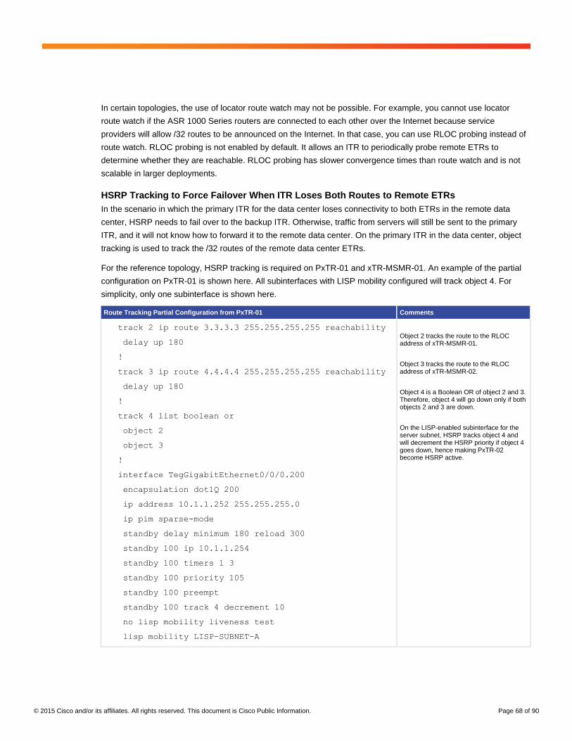
© 2015 Cisco and/or its affiliates. All rights reserved. This document is Cisco Public Information. Page 68 of 90
In certain topologies, the use of locator route watch may not be possible. For example, you cannot use locator
route watch if the ASR 1000 Series routers are connected to each other over the Internet because service
providers will allow /32 routes to be announced on the Internet. In that case, you can use RLOC probing instead of
route watch. RLOC probing is not enabled by default. It allows an ITR to periodically probe remote ETRs to
determine whether they are reachable. RLOC probing has slower convergence times than route watch and is not
scalable in larger deployments.
HSRP Tracking to Force Failover When ITR Loses Both Routes to Remote ETRs
In the scenario in which the primary ITR for the data center loses connectivity to both ETRs in the remote data
center, HSRP needs to fail over to the backup ITR. Otherwise, traffic from servers will still be sent to the primary
ITR, and it will not know how to forward it to the remote data center. On the primary ITR in the data center, object
tracking is used to track the /32 routes of the remote data center ETRs.
For the reference topology, HSRP tracking is required on PxTR-01 and xTR-MSMR-01. An example of the partial
configuration on PxTR-01 is shown here. All subinterfaces with LISP mobility configured will track object 4. For
simplicity, only one subinterface is shown here.
Route Tracking Partial Configuration from PxTR-01 Comments
track 2 ip route 3.3.3.3 255.255.255.255 reachability
delay up 180
!
track 3 ip route 4.4.4.4 255.255.255.255 reachability
delay up 180
!
track 4 list boolean or
object 2
object 3
!
interface TegGigabitEthernet0/0/0.200
encapsulation dot1Q 200
ip address 10.1.1.252 255.255.255.0
ip pim sparse-mode
standby delay minimum 180 reload 300
standby 100 ip 10.1.1.254
standby 100 timers 1 3
standby 100 priority 105
standby 100 preempt
standby 100 track 4 decrement 10
no lisp mobility liveness test
lisp mobility LISP-SUBNET-A
Object 2 tracks the route to the RLOC address of xTR-MSMR-01.
Object 3 tracks the route to the RLOC address of xTR-MSMR-02.
Object 4 is a Boolean OR of object 2 and 3. Therefore, object 4 will go down only if both objects 2 and 3 are down.
On the LISP-enabled subinterface for the server subnet, HSRP tracks object 4 and will decrement the HSRP priority if object 4 goes down, hence making PxTR-02 become HSRP active.

© 2015 Cisco and/or its affiliates. All rights reserved. This document is Cisco Public Information. Page 69 of 90
Figure 18 shows a failure scenario in which PxTR-01 loses connectivity to the other LISP routers: for example, if
the links go down or a circuit failure occurs on the service provider network.
Figure 18. PxTR-01 Loses Connectivity to the Other LISP Routers
Before Failure
PxTR-01#show track brief
Track Object Parameter Value Last Change
2 ip route 3.3.3.3/32 reachability Up 01:34:05
3 ip route 4.4.4.4/32 reachability Up 01:34:05
4 list boolean Up 01:34:05
PxTR-01#show standby brief
P indicates configured to preempt.
|
Interface Grp Pri P State Active Standby Virtual IP
Te0/0.200 100 105 P Active local 10.1.1.253 10.1.1.254
Te0/0.201 100 105 P Active local 10.1.2.253 10.1.2.254
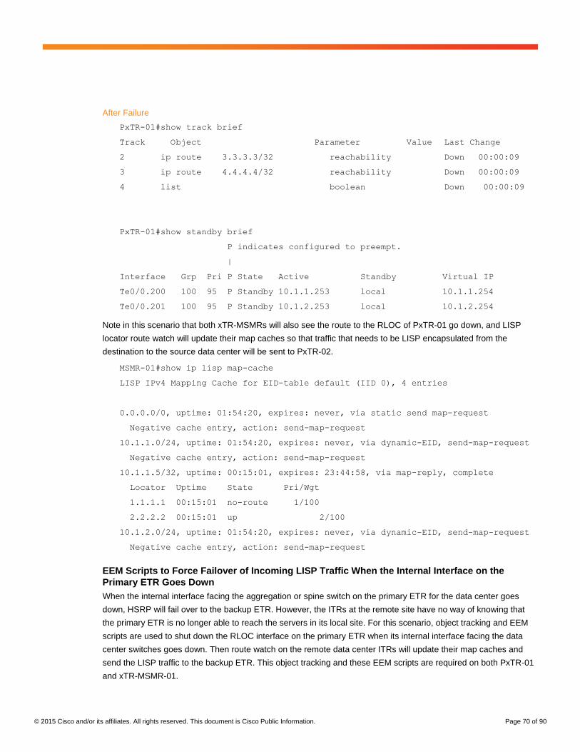
© 2015 Cisco and/or its affiliates. All rights reserved. This document is Cisco Public Information. Page 70 of 90
After Failure
PxTR-01#show track brief
Track Object Parameter Value Last Change
2 ip route 3.3.3.3/32 reachability Down 00:00:09
3 ip route 4.4.4.4/32 reachability Down 00:00:09
4 list boolean Down 00:00:09
PxTR-01#show standby brief
P indicates configured to preempt.
|
Interface Grp Pri P State Active Standby Virtual IP
Te0/0.200 100 95 P Standby 10.1.1.253 local 10.1.1.254
Te0/0.201 100 95 P Standby 10.1.2.253 local 10.1.2.254
Note in this scenario that both xTR-MSMRs will also see the route to the RLOC of PxTR-01 go down, and LISP
locator route watch will update their map caches so that traffic that needs to be LISP encapsulated from the
destination to the source data center will be sent to PxTR-02.
MSMR-01#show ip lisp map-cache
LISP IPv4 Mapping Cache for EID-table default (IID 0), 4 entries
0.0.0.0/0, uptime: 01:54:20, expires: never, via static send map-request
Negative cache entry, action: send-map-request
10.1.1.0/24, uptime: 01:54:20, expires: never, via dynamic-EID, send-map-request
Negative cache entry, action: send-map-request
10.1.1.5/32, uptime: 00:15:01, expires: 23:44:58, via map-reply, complete
Locator Uptime State Pri/Wgt
1.1.1.1 00:15:01 no-route 1/100
2.2.2.2 00:15:01 up 2/100
10.1.2.0/24, uptime: 01:54:20, expires: never, via dynamic-EID, send-map-request
Negative cache entry, action: send-map-request
EEM Scripts to Force Failover of Incoming LISP Traffic When the Internal Interface on the
Primary ETR Goes Down
When the internal interface facing the aggregation or spine switch on the primary ETR for the data center goes
down, HSRP will fail over to the backup ETR. However, the ITRs at the remote site have no way of knowing that
the primary ETR is no longer able to reach the servers in its local site. For this scenario, object tracking and EEM
scripts are used to shut down the RLOC interface on the primary ETR when its internal interface facing the data
center switches goes down. Then route watch on the remote data center ITRs will update their map caches and
send the LISP traffic to the backup ETR. This object tracking and these EEM scripts are required on both PxTR-01
and xTR-MSMR-01.

© 2015 Cisco and/or its affiliates. All rights reserved. This document is Cisco Public Information. Page 71 of 90
A partial configuration from PxTR-01 showing the object tracking and EEM scripts is shown here.
Interface Tracking and EEM Scripts from PxTR-01 Comments
track 1 interface TegGigabitEthernet0/0/0 line-protocol
delay up 180
!
event manager applet INTERNAL-INTERFACE-IS-DOWN
event track 1 state down
action 1.0 cli command "enable"
action 1.1 cli command "conf t"
action 2.0 cli command "interface loop0"
action 3.0 cli command "shut"
action 9.0 syslog msg "INTERNAL INTERFACE DOWN, RLOC
1.1.1.1 HAS BEEN SHUTDOWN"
!
event manager applet INTERNAL-INTERFACE-IS-UP
event track 1 state up
action 1.0 cli command "enable"
action 1.1 cli command "config t"
action 2.0 cli command "interface loop0"
action 3.0 cli command "no shut"
action 9.0 syslog msg "INTERNAL INTERFACE UP, RLOC
1.1.1.1 HAS BEEN RESTORED"
Tracked object 1 tracks the internal interface facing the aggregation switches.
An EEM script is used to shut down the RLOC interface loopback 0 on PxTR-01 if the interface Ten0/0/0 facing the aggregation switch goes down (tracked object 1). This configuration is required so that the xTR-MSMRs will see the RLOC of PxTR-01 go down, and so they won’t forward LISP traffic to it during this failure scenario. This setting will force the incoming LISP traffic over to PxTR-02.
Another EEM script is used to bring the RLOC interface loopback 0 on PxTR-01 back up after the interface Ten0/0/0 facing the aggregation switch comes back up.
Figure 19 shows this failure scenario. Note that in this case, there will be an OSPF equal-cost path between PxTR-
02 and xTR-MSMR-01, so traffic will be load-balanced across the two paths. For simplicity, the figure just shows
one path.

© 2015 Cisco and/or its affiliates. All rights reserved. This document is Cisco Public Information. Page 72 of 90
Figure 19. Failure of Internal Interface on PxTR-01
Failover of Traffic between a Server in the Destination Data Center and a WAN Site Not Enabled
for LISP
Both xTR-MSMR routers use the PxTRs as their proxy egress tunnel routers with the use-PETR function.
Beginning in Cisco IOS XE Release 3.11, LISP locator route watch can be used to automatically track the
reachability of PETRs. Therefore, if PxTR-01 becomes unreachable, the xTR-MSMR routers will update their map
caches to send traffic destined for the WAN to PxTR-02 (Figure 20).

© 2015 Cisco and/or its affiliates. All rights reserved. This document is Cisco Public Information. Page 73 of 90
Figure 20. Failover of WAN Traffic When Primary PETR Fails
Note that prior to Cisco IOS XE 3.11, route watch was not available for the use-PETR function. For versions prior
to Cisco IOS XE 3.11, an EEM script can be used to reconfigure the use-PETR priorities in the event that the ITR
loses its route to the primary PETR.
Before Failure of PxTR-01
xTR-MSMR-01#show ip lisp forwarding eid remote
Prefix Fwd action Locator status bits
0.0.0.0/0 signal 0x00000000
packets/bytes 1/100
10.1.1.0/24 signal 0x00000000
packets/bytes 2/200
10.1.1.5/32 encap 0x00000003
packets/bytes 750114/75011400
10.1.2.0/24 signal 0x00000000
packets/bytes 0/0
10.32.0.0/11 fwd native 0x00000000
packets/bytes 59450/5945000

© 2015 Cisco and/or its affiliates. All rights reserved. This document is Cisco Public Information. Page 74 of 90
xTR-MSMR-01#show ip lisp forwarding eid remote 10.32.0.0
Prefix Fwd action Locator status bits
10.32.0.0/11 fwd native 0x00000000
packets/bytes 66045/6604500
path list 051773F4, flags 0x49, 5 locks, per-destination
ifnums:
LISP0(12): 1.1.1.1
1 path
path 04633A40, path list 051773F4, share 100/100, type attached nexthop, for
IPv4
nexthop 1.1.1.1 LISP0, adjacency IP midchain out of LISP0, addr 1.1.1.1
050F71E0
1 output chain
chain[0]: IP midchain out of LISP0, addr 1.1.1.1 050F71E0 IP adj out of
TenGigabitEthernet1/0/0, addr 192.168.100.5 050F6D20
After Failure of PxTR-01
xTR-MSMR-01#show ip lisp forwarding eid remote 10.32.0.0
Prefix Fwd action Locator status bits
10.32.0.0/11 fwd native 0x00000000
packets/bytes 168796/16879600
path list 051776C4, flags 0x49, 5 locks, per-destination
ifnums:
LISP0(12): 2.2.2.2
1 path
path 04633650, path list 051776C4, share 100/100, type attached nexthop, for
IPv4
nexthop 2.2.2.2 LISP0, adjacency IP midchain out of LISP0, addr 2.2.2.2
050F6AC0
1 output chain
chain[0]: IP midchain out of LISP0, addr 2.2.2.2 050F6AC0 IP adj out of
TenGigabitEthernet0/1/0, addr 192.168.100.14 050F7310
Optional Deployment Variations
This section discusses some deployment options that vary from the reference topology described previously:
● LISP configuration in an environment with multiple VRF instances to support overlapping IP addresses
between multiple tenants
● Coexistence with OTV
● Deployment of this solution without redundancy
● Topology that uses a non-LISP device as the default gateway in the new data center
● LISP configuration for interfaces that have secondary IP addresses

© 2015 Cisco and/or its affiliates. All rights reserved. This document is Cisco Public Information. Page 75 of 90
Environments with Multiple VRF Instances
LISP natively supports multitenancy. In the LISP packet header, the field Instance ID is used to provide a means of
maintaining unique address spaces (or address space segmentation) in the control and data planes. Instance IDs
are numerical tags.
Virtualization at the device level uses VRF to create multiple instances of Layer 3 routing tables. LISP binds VRFs
to instance IDs (IIDs), and then these IIDs are included in the LISP header to provide data-plane (traffic flow) and
control-plane separation for single-hop or multihop needs. In other words, LISP binds VRF instances to instance
IDs to extend device virtualization to provide networkwide virtualization.
Recall that LISP implements locator and ID separation and, in so doing, creates two namespaces: EIDs and
RLOCs. Thus, LISP virtualization can consider both EID and RLOC namespaces for virtualization: that is, either or
both can be virtualized.
● EID virtualization: Enabled by binding a LISP instance ID to an EID VRF instance
● RLOC virtualization: Enabled by tying locator addresses and associated mapping services to the specific
VRF instance in which they can be reached
Because LISP considers virtualization of both EID and RLOC namespaces, two models of operation are defined:
shared and parallel.
With the solution described in this document, you can use either the shared or the parallel LISP virtualization
model. The remainder of this section focused on the shared model, in which VRF instances are used to segment
the EID space, and they use a RLOC space configured in the global table.
Figure 21 shows LISP shared-model virtualization, which resolves EIDs in VRF instances tied to instance IDs.
RLOC addresses are resolved in a common (shared) address space. The default (global) routing table is shown in
the figure as the shared space.
Figure 21. LISP Shared Virtualization Model
The following configuration example defines a VRF instance named BIO. This example shows the main differences
between the configurations described previously in this document and a configuration that allows the solution to
support a multi-VRF environment. Note that the route detector (RD), interface, IP address, and IEEE 802.1Q
values used here are examples only.
In the xTR configuration shown here, VRF BIO is mapped to LISP instance ID 102. In this example, LISP mobility
is enabled for subnet 172.16.133.0/24, which is within the BIO VRF instance. For a multihomed environment with
two xTRs in the data center, multicast routing and PIM need to be enabled on the xTRs for the VRF instance. This
configuration is required for correct processing of the LISP multicast map-notify message.

© 2015 Cisco and/or its affiliates. All rights reserved. This document is Cisco Public Information. Page 76 of 90
vrf definition BIO
rd 119:1
ip multicast-routing vrf BIO distributed
interface Loopback1
vrf forwarding BIO
ip address 111.1.1.1 255.255.255.255
ip pim sparse-mode
interface TenGigabitEthernet0/0/0.849
description EID-BIO
encapsulation dot1Q 849
vrf forwarding BIO
ip address 172.16.133.252 255.255.255.0
ip pim sparse-mode
standby delay minimum 180 reload 300
standby 89 ip 172.16.133.254
standby 89 priority 105
standby 89 preempt
standby 89 track 1 decrement 10
no lisp mobility liveness test
lisp mobility LISP-BIO-1
router lisp
locator-set EXAMPLE
11.11.11.11 priority 1 weight 100
22.22.22.22 priority 2 weight 100
exit
eid-table vrf BIO instance-id 102 << Mapping from VRF to instance ID
dynamic-eid LISP-BIO-1
database-mapping 172.16.133.0/24 locator-set EXAMPLE
map-notify-group 239.0.0.3
exit
ip pim vrf BIO rp-address 111.1.1.1

© 2015 Cisco and/or its affiliates. All rights reserved. This document is Cisco Public Information. Page 77 of 90
LISP control-plane messages include the instance ID so that EIDs can be registered and resolved with their
corresponding instance IDs. Hence, the map servers must also be instance-ID aware. The mapping database
stores the instance ID with the EID-to-RLOC mappings. The sample partial map-server configuration shown here
will accept more specific map registers for EIDs in the 172.16.0.0/16 network that have an instance ID of 102 and
the correct authentication key.
router lisp
site DC-MIGRATION
authentication-key CISCO123
eid-prefix instance-id 102 172.16.0.0/16 accept-more-specifics
exit
LISP Coexistence with OTV
LISP supports a deployment mode called extended subnet mode, in which LISP is used for the same VLAN and
subnet as a LAN extension solution (for example, OTV or VPLS). In this case, LISP provides path optimization, and
the LAN extension solution provides IP mobility.
The solution presented here does not use LISP extended subnet mode. Therefore, LISP is used exclusively to
provide IP mobility (without OTV or any other Layer 2 extension technology). However, note that you can combine
OTV and LISP on the same ASR 1000 Series router, using OTV for certain VLANs and using LISP for others. For
example, you can use OTV to extend VLAN 10, which has subnet 10.10.10.0/24 configured on it, while using LISP
to provide IP mobility for subnet 10.20.20.0/24 and VLAN 20. Note that LISP does not extend VLANs; therefore,
the VLAN ID is irrelevant for LISP-based forwarding.
This capability offered by the ASR 1000 Series routers, in which OTV is used for some VLANs and LISP is used for
others, is useful when deploying the solution presented here in certain scenarios. For example, it is useful if you
discover during the deployment process that a specific application requires you to preserve Layer 2 adjacency
between hosts in the original (brownfield) data center and hosts migrated to the new data center: for example, for
members of a cluster that communicate at Layer 2 through link local multicast traffic. This requirement for Layer 2
adjacency between hosts is becoming less relevant because most hosts now communicate at Layer 3. However,
if necessary, you can use OTV to meet this requirement for that specific VLAN while using LISP for all other
subnets.
Another scenario in which the use of OTV for a particular VLAN and subnet is useful is the case in which no IP
addresses are available on the subnet on which mobility is desired. As discussed in the section “Deploying LISP on
Cisco ASR 1000 Series for Data Center Migration,” n the brownfield (original) data center in which the ASRs
are connected to the subnet in which mobility is required, three IP addresses from that subnet are required for
implementation of the solution. One address is needed for each ASR, and one address is used as the virtual IP
address (HSRP IP) shared between the routers. Sometimes, no IP addresses may be available on the subnet in
which mobility is required. In this case, LISP can’t be implemented, and the use of OTV is an attractive alternative.
The following example shows a configuration that uses both OTV and LISP on the same internal interface. The
interface from the ASR connected to the subnet and VLAN in which mobility is required uses OTV to extend VLAN
621, and it uses LISP for subnet 11.10.1.0/24, which is associated with VLAN 501.

© 2015 Cisco and/or its affiliates. All rights reserved. This document is Cisco Public Information. Page 78 of 90
OTV Basic Configuration: VLAN 620 Used as OTV Site VLAN, and VLAN 621 Extended by OTV to Remote Site
otv site bridge-domain 620
otv isis hello-interval 3
!
!ip igmp snooping querier version 3
ip igmp snooping querier
!
otv site-identifier ACDC.ACDC.0001
otv isis Overlay1
log-adjacency-changes all
bridge-domain 621
interface Overlay1
no ip address
otv join-interface TenGigabitEthernet0/2/0
no otv filter-fhrp
otv use-adjacency-server A.B.C.D A.B.C.E unicast-only
otv isis hello-interval 3
service instance 621 ethernet
encapsulation dot1q 621
bridge-domain 621
Interface Configuration: VLAN 621 Is Extended to Remote Site through OTV, and LISP Provides IP Mobility for
Subnet 11.10.1.0/24 Associated with VLAN 501 (VLAN 620 Is the OTV Site VLAN)
interface GigabitEthernet0/0/1
description INTERNAL INTERFACE TO DC FOR OTV TRANSPORT
no ip address
service instance 620 ethernet
encapsulation dot1q 620
bridge-domain 620
!
service instance 621 ethernet
encapsulation dot1q 621
bridge-domain 621
interface GigabitEthernet0/0/1.2000
description SUB-INTERFACE USED FOR LISP MOBILITY
encapsulation dot1Q 500
ip address AA.BB.CC.DD 255.255.255.0
standby 20 ip AA.BB.CC.DE

© 2015 Cisco and/or its affiliates. All rights reserved. This document is Cisco Public Information. Page 79 of 90
standby 20 timers 1 3
standby 20 preempt
no lisp mobility liveness test
lisp mobility LISP2060
Nonredundant Deployments
The previous reference diagrams and detailed deployment discussions in this document describe and recommend
deployment of a pair of ASR 1000 Series routers in each data center, therefore providing redundancy. However,
you can also deploy the solution using a single ASR 1000 Series router in each data center, without redundancy. In
addition to the obvious risks of lack of redundancy, you must consider what happens in the event of a reboot or
failure and how you will recover the router connected to the brownfield (original) data center.
In the brownfield data center, the ASR 1000 Series router is not the default gateway and therefore, as discussed in
the section “Implementation Details for the Brownfield (Source) Data Center,” after implementation EID detection is
performed by using an EEM script. In nonredundant deployments, after the ASR in the brownfield reloads, it will
come up with an empty EID table and so the same EEM script used during initial deployment must be run. Until the
EEM script is finished, packet loss and intermittent communication may occur in the network because, for example,
traffic from a host in the greenfield data center to a host in the brownfield that has not yet been detected would be
dropped because the map server won’t yet contain an entry.
In summary, although it is technically possible to deploy this solution without redundancy, Cisco recommends that
it be deployed with redundant nodes unless the situation described here is understood and acceptable.
Secondary IP Addressing
Occasionally in data centers, a server subnet may run out of IP addresses, and secondary subnets need to be
used for the same server VLAN. LISP mobility supports multiple dynamic-EID prefixes configured on the same
subinterface. The subinterface on which the LISP dynamic-EID prefixes are configured is local to the LISP router.
Therefore, on one site multiple subnets can belong to one VLAN, and on another site these subnets can be
assigned to individual VLANs. Hence, LISP mobility for data center migrations enables the network administrator
to plan a new and improved VLAN numbering scheme for the new data center.
If multiple subnets share the same VLAN in the source data center, and if secondary addresses are used on the
VLAN interfaces on aggregation switches, then multiple LISP dynamic EIDs can be used on respective
subinterfaces on the ASR 1000 Series routers. In the destination data center, the subnets can be presented on a
single VLAN or split into individual VLANs. The following example shows the configuration required to enable LISP
mobility for two subnets in the same VLAN 200 in source data centers 10.1.1.0/24 and 10.1.3.0/24. In the
destination data center, these subnets have been split into VLAN 4000 and VLAN 4003, respectively. Note that for
LISP mobility, the xTR does not need an IP address on the subinterface in the same subnet as the dynamic EIDs.
For simplicity, in the following example, the HSRP configuration has been omitted. Only a single HSRP group is
required using multiple dynamic-EID prefixes on the same subinterface.

© 2015 Cisco and/or its affiliates. All rights reserved. This document is Cisco Public Information. Page 80 of 90
Partial Configuration from PxTR-01 with Two Subnets on Single VLAN Comments
router lisp
locator-set DC1
1.1.1.1 priority 1 weight 100
2.2.2.2 priority 2 weight 100
exit
!
eid-table default instance-id 0
dynamic-eid LISP-SUBNET-A
database-mapping 10.1.1.0/24 locator-set DC1
map-notify-group 239.0.0.1
exit
!
dynamic-eid LISP-SUBNET-C
database-mapping 10.1.3.0/24 locator-set DC1
map-notify-group 239.0.0.3
!
interface TegGigabitEthernet0/0/0.200
encapsulation dot1Q 200
ip address 10.1.1.252 255.255.255.0
no lisp mobility liveness test
lisp mobility LISP-SUBNET-A
lisp mobility LISP-SUBNET-C
Two LISP dynamic-EID prefixes are defined for the two subnets: 10.1.1.0/24 and 10.1.3.0/24.
Both LISP dynamic EIDs are assigned to interface Ten0/0/0.200.
Partial Configuration from xTR-MSMR-01 with Single Subnet on Each VLAN Comments
router lisp
locator-set DC2
3.3.3.3 priority 1 weight 100
4.4.4.4 priority 2 weight 100
exit
!
eid-table default instance-id 0
dynamic-eid LISP-SUBNET-A
database-mapping 10.1.1.0/24 locator-set DC2
map-notify-group 239.0.0.1
exit
!
dynamic-eid LISP-SUBNET-C
database-mapping 10.1.3.0/24 locator-set DC2
Two LISP dynamic-EID prefixes are defined for the two subnets: 10.1.1.0/24 and 10.1.3.0/24.
LISP dynamic EID for subnet 10.1.1.0/24 is assigned to interface Ten0/0/0.4000.
LISP dynamic EID for subnet 10.1.3.0/24 is assigned to interface Ten0/0/0.4003.

© 2015 Cisco and/or its affiliates. All rights reserved. This document is Cisco Public Information. Page 81 of 90
Partial Configuration from xTR-MSMR-01 with Single Subnet on Each VLAN Comments
map-notify-group 239.0.0.3
!
interface TegGigabitEthernet0/0/0.4000
encapsulation dot1Q 4000
ip address 10.1.1.252 255.255.255.0
no lisp mobility liveness test
lisp mobility LISP-SUBNET-A
!
interface TegGigabitEthernet0/0/0.4003
encapsulation dot1Q 4003
ip address 10.1.3.252 255.255.255.0
no lisp mobility liveness test
lisp mobility LISP-SUBNET-C
Support for Stateful Devices
Most data centers have some form of stateful devices such as firewalls or load balancers. To maintain the state,
traffic must traverse these devices symmetrically. Therefore, any data center migration solution needs to consider
stateful devices. This section looks at design options for the placement of stateful devices in the source data
center.
Figure 22 shows a sample topology with stateful devices, in this case, firewalls, in the source and destination data
centers.

© 2015 Cisco and/or its affiliates. All rights reserved. This document is Cisco Public Information. Page 82 of 90
Figure 22. Reference Topology with Firewalls in Source and Destination Data Centers
Firewall Placement between Aggregation and Core Layers
The most common deployment of firewalls in traditional three-tier data centers is between the aggregation and core
layers. In this design, the server’s default gateway is the aggregation switches. The firewall inside interface will
logically connect at Layer 3 to the aggregation switches, and the firewall outside interfaces will logically connect at
Layer 3 to the core switches. No special configuration is required for the LISP data center migration solution to
work with this type of firewall placement. Traffic to and from servers that have migrated to the destination data
center will route symmetrically through the firewalls.
Figure 23 shows a logical Layer 3 routing representation of this design as well as the traffic flow to and from the
WAN and a server that has been migrated to the destination data center.
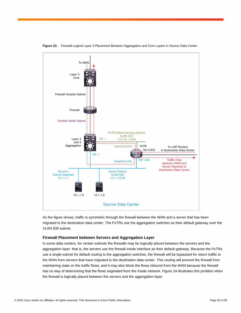
© 2015 Cisco and/or its affiliates. All rights reserved. This document is Cisco Public Information. Page 83 of 90
Figure 23. Firewall Logical Layer 3 Placement Between Aggregation and Core Layers in Source Data Center
As the figure shows, traffic is symmetric through the firewall between the WAN and a server that has been
migrated to the destination data center. The PxTRs use the aggregation switches as their default gateway over the
VLAN 500 subnet.
Firewall Placement between Servers and Aggregation Layer
In some data centers, for certain subnets the firewalls may be logically placed between the servers and the
aggregation layer: that is, the servers use the firewall inside interface as their default gateway. Because the PxTRs
use a single subnet for default routing to the aggregation switches, the firewall will be bypassed for return traffic to
the WAN from servers that have migrated to the destination data center. This routing will prevent the firewall from
maintaining state on the traffic flows, and it may also block the flows inbound from the WAN because the firewall
has no way of determining that the flows originated from the inside network. Figure 24 illustrates this problem when
the firewall is logically placed between the servers and the aggregation layer.

© 2015 Cisco and/or its affiliates. All rights reserved. This document is Cisco Public Information. Page 84 of 90
Figure 24. Firewall Logical Layer 3 Placement Between Servers and Aggregation Layer in Source Data Center
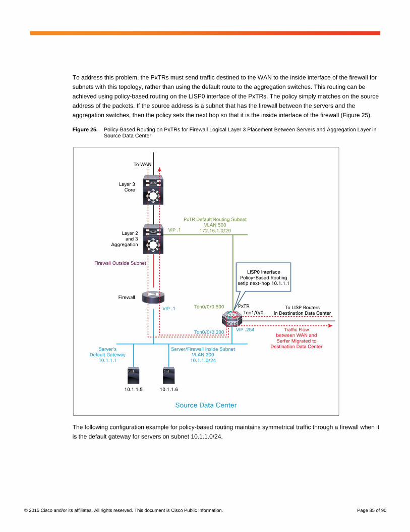
© 2015 Cisco and/or its affiliates. All rights reserved. This document is Cisco Public Information. Page 85 of 90
To address this problem, the PxTRs must send traffic destined to the WAN to the inside interface of the firewall for
subnets with this topology, rather than using the default route to the aggregation switches. This routing can be
achieved using policy-based routing on the LISP0 interface of the PxTRs. The policy simply matches on the source
address of the packets. If the source address is a subnet that has the firewall between the servers and the
aggregation switches, then the policy sets the next hop so that it is the inside interface of the firewall (Figure 25).
Figure 25. Policy-Based Routing on PxTRs for Firewall Logical Layer 3 Placement Between Servers and Aggregation Layer in Source Data Center
The following configuration example for policy-based routing maintains symmetrical traffic through a firewall when it
is the default gateway for servers on subnet 10.1.1.0/24.

© 2015 Cisco and/or its affiliates. All rights reserved. This document is Cisco Public Information. Page 86 of 90
Policy-Based Routing on PxTR Routers for Subnets with Firewall Between Servers and Aggregation Layer
Comments
interface LISP0
ip policy route-map PBR-LISP
!
access-list 101 permit ip 10.1.1.0 0.0.0.255 any
!
route-map PBR-LISP permit 10
match ip address 101
set ip next-hop recursive 10.1.1.1
!
This policy will set the next hop to 10.1.1.1 for any traffic that the PxTR receives from the destination data center that needs to be routed.
Note that the recursive option is needed, using the set ip next-hop command. This configuration is required because the PxTR will have a /32 route in its routing table for firewall address 10.1.1.1 learned from LISP.
The recursive option is needed for any routes that are not connected routes in the routing table.
Steps for Troubleshooting LISP Mobility
You can use the following main steps to troubleshoot LISP:
Step 1. Verify the underlay routing.
Step 2. Verify the LISP control plane.
Step 3. Verify the LISP data plane.
Step 1: Verify the Underlay Routing
The underlay routing is the IP routing for the RLOC address space. LISP xTRs in the same RLOC routing domain
must have IP reachability to each other’s RLOC address. The problem with the underlay routing will most likely
affect multiple EID prefixes, or all of them.
Step 2: Verify the LISP Control Plane
Before an xTR can begin to LISP encapsulate data packets to an EID located at another LISP site, it must have a
map-cache entry for the destination EID. The map-cache entries are based on data packets received by an ITR
destined for remote EIDs. If the ITR does not create a map-cache entry for a destination EID upon receipt of
packets for that EID, then troubleshoot the LISP control plane. When troubleshooting the LISP control plane, you
should start with the ETR and work back to the ITR. You need to take this approach in both directions, because a
LISP xTR will be an ITR in one traffic direction and an ETR in the other traffic direction.
Step 2.1: Verify that the ETR has Detected the Dynamic EIDs.
Use the following commands to check the ETR:
show lisp dynamic-eid summary
show ip lisp database [EID-prefix]
If the ETR doesn’t detect local dynamic EIDs, then check the Layer 2 connectivity, LISP dynamic-EID
configuration, multicast, and HSRP.
Step 2.2: Verify that the ETR has Registered the EIDs with the Map Server.
Use the following command to check the map server:
show lisp site [ detail ]

© 2015 Cisco and/or its affiliates. All rights reserved. This document is Cisco Public Information. Page 87 of 90
Step 2.3: Verify that ITR Adds an Entry in its Map Cache when Traffic is Sent to the Destination EID.
Use the following command to check the ITR:
show ip lisp map-cache [ destination-EID | detail ]
Step 3: Verify the LISP Data Plane
When the LISP ITRs have map-cache entries for the remote EIDs, then packets received by the ITR destined for
the remote EID should be LISP encapsulated. Assuming that those packets reach the remote site ETR, they
should then be decapsulated and forwarded to the EID.
Step 3.1: Check the Hardware Forwarding Table (Cisco Express Forwarding [CEF] Table).
show ip cef [prefix | {detail| internal} ]
Step 3.2: Verify that ITR is LISP Encapsulating the Data Packets.
show ip lisp forwarding eid remote [destination-EID | detail ]
Step 3.3: Verify that ETR is Receiving the LISP-Encapsulated Data Packets.
You can use Cisco NetFlow ingress on ETR or Wireshark to verify LISP encapsulation. To troubleshoot, you can
check whether LISP data-plane packets (on UDP destination port 4341) are being blocked on the transport
network.
Conclusion
This document provided deployment guidance for a solution that enables IP addresses preservation during data
center migration with Cisco Locator/ID Separation Protocol (LISP; RFC 6830) and Cisco ASR 1000 Series routers.
Customers who have adopted this solution have been able to perform data center migration more quickly, and with
much lower risk. In fact, some customers expect to reduce migration time by up to 95 percent.
The solution discussed here uses LISP running on ASR 1000 Series routers. The benefits delivered by this solution
include:
● Capability to decouple server migration activities (planning, affinity-group migration, schedules, cutover,
etc.) from network constraints
● IP address mobility: the IP address, subnet mask, default gateway, and hostname of migrated servers do
not need to change
● Capability to perform migration in small increments, enabling single-server migration (if required) as well as
the migration of a group of servers
Cisco Services is available to assist with the planning, design, deployment, support, and optimization of the
solution described on this document.

© 2015 Cisco and/or its affiliates. All rights reserved. This document is Cisco Public Information. Page 88 of 90
Appendix: Overview of LISP
Cisco Locator/ID Separation Protocol (LISP; RFC 6830) underlies the solution described in this document. This
appendix provides a brief overview of LISP.
Locator/Identifier Separation Protocol
With the emergence of cloud architecture, innovation is required in networking to allow IP to gain two mandatory
missing features: IP mobility and VPNs.
The Locator Identity Separation Protocol (LISP) is a routing architecture that creates a new model by splitting the
device identity, known as an endpoint identifier (EID), and its location, known as its routing locator (RLOC), into two
different numbering spaces. This capability brings renewed scale and flexibility to the network in a single protocol,
enabling mobility, scalability, and security.
LISP is an overlay routing protocol in the sense that it allows decoupling of the core transport, which can be any
IP transport method, from the edge, which can be any IP application site. LISP is intended for the cloud because it
allows dynamic resource provisioning independent of the network infrastructure. Any IP address can be positioned
anywhere it is needed.
LISP is a routing architecture, not a feature. It gives IP a full set of capabilities that it does not natively have. LISP
enables IP address portability in two ways. It allows a host to be moved anywhere without the need to change the
host IP address. It also allows an edge host IP address to be defined independent of the site IP structure on which
it will reside. The decoupling of the application definition from the network is critical for cloud flexibility.
LISP enables network VPN, allowing interconnecting virtual routing and forwarding (VRF) instances over any IP
network, giving to IP a capability similar to Multiprotocol Label Switching (MPLS), but not limited to the core of the
network, because virtualization is extended to any edge.
Cloud solutions require a huge degree of scalability, and LISP also differentiates itself in this area. LISP is based
on a “pull” model. Similar to Domain Name System (DNS), LISP has one central mapping system in which any
node registers. When somewhere else in an organization an association between an edge identity and a routing
location is required, the information is pulled from this mapping database. This feature differentiates LISP from
Open Shortest Path First (OSPF) and Border Gateway Protocol (BGP), which are “push” models, in which the full
routing information is stored in the forwarding plane of every node. Like DNS, LISP is massively scalable.
The overlay aspect of LISP is also important. LISP is an over-the-top technology, tunneling over the IP core and all
the IP edge flows. This tunneling allows LISP to use any type of transport - the Internet, a multiple-autonomous
system (multi-AS) network, a private infrastructure, IPv4 or IPv6, etc. - as well as IP VPN services provided through
MPLS. LISP can be encrypted natively with point-to-point or multipoint IP Security (IPsec). This isolation of the
edge environment that is independent of the transport is critical for cloud architecture.
Furthermore, LISP is an open-standard service with no intellectual property rights. LISP is also very active at the
IETF ([email protected]) and is the object of several multivendor implementations.

© 2015 Cisco and/or its affiliates. All rights reserved. This document is Cisco Public Information. Page 89 of 90
LISP Basic Concepts
To understand LISP, you need to understand the concept of “location-to-identity separation” (Figure 26).
Figure 26. Location-to-Identity Separation
In traditional IP, the IP edge routing subnets are advertised all over the network using either Interior Gateway
Protocol (IGP) or Exterior Gateway Protocol (EGP). Advertisement of any host address (subnet mask /32) is rare.
Usually, subnets larger than or equal to /24 are used. In IP, all routes are advertised everywhere and installed in
the forwarding plane. Therefore, it is important to limit the number of entries. To do so, IP subnets are strictly
limited to a geographical area, and a subnet is managed by only one pair of routers - the default gateway - implying
that if a node is moved, its IP address must be updated accordingly to the local default gateway and subnet. This
constraint is cumbersome. To avoid it, organizations increasingly are using cross-site VLAN extensions, with all the
drawbacks this approach can entail.
With LISP, such constraints disappear. LISP splits the host ID (EID) from the RLOC, allowing any host to move
from location to location while keeping its unique identity.
LISP architecture consists of several elements, including the following:
● Egress tunnel router (ETR)
◦ The ETR registers the EID address space for which it is authorized.
◦ It is identified by one (or more) RLOCs.
◦ It receives and decapsulates the LISP frames.

© 2015 Cisco and/or its affiliates. All rights reserved. This document is Cisco Public Information. Page 90 of 90
● Map server
◦ This server is the database in which all EID and RLOC associations are stored.
◦ The server can be deployed on a pair of devices.
◦ Alternatively, the server can be a hierarchy of devices, organized like a DNS system for an
implementation of massive scale (LISP delegate database tree [DDT]).
● Ingress tunnel router (ITR)
◦ The ITR sends requests to the map resolver.
◦ It populates its local map cache with the learned association.
◦ It is responsible for performing LISP encapsulation.
● Map resolver
◦ The map resolver receives request and selects the appropriate map server.
● Proxy xTR
◦ The proxy egress or ingress tunnel router is the point of interconnection between an IP network and a
LISP network, playing the role of ITR and ETR at this peering point.
An ETR is authoritative for a subnet, and it registers it using a map-register message to the map server.
When triggered on the data plane by a packet destined for a remote EID, the ITR sends a map request to the map
resolver, which forwards it to the right map server, which then forwards it to the authoritative ETR. This ETR replies
to the requesting ITR using a map-reply message that contains the list of RLOCs that can reach the requested EID.
This list includes the characteristics of the RLOCs: use priority and weighted load repartition.
For More Information
If you have questions, comments, suggestions, or concerns, please contact the Cisco LISP team by sending an
email to [email protected].
The Cisco LISP team is proud to provide direct access and support to customers and partners. We will do our best
to answer all emails in a prompt and accurate manner.
Printed in USA C11-734769-00 06/15