press esco copyright · and valve losses are negligible. evaporating pressure the evaporating...
TRANSCRIPT

Copyri
ght E
sco Pres
s
Copyright © 2002
ESCO Press
All rights reserved. Except as permitted under
The United States Copyright Act of 1976, no part
of this publication may be reproduced or distributed
In any form or means, or stored in a database
or retrieval system, without the prior written
permission of the publisher, ESCO Press.
ISBN 1-930044-13-5
This book was written as a general guide The authors and publisher have neither liability
nor can they be responsible to any person or entity for any misunderstanding, misuse, or
misapplication that would cause loss or damage f any kind, including loss of rights, material,
or personal injury, alleged to be caused directly or indirectly by the information contained in
this book.
Cover photo supplied by Honeywell International.
This image may not be reproduced ith ut written authorization from Honeywell. Genetron ® and AZ 20 ® are registered trademarks of Hon
eywell. Honeywell has no revi wed the material contained herein, and assumes no liability or responsibility for its use.
Printed in the United States of America
7 6 5 4 3 2 1 Cop
yrigh
t Esc
o Pres
s

Copyright © 2002
ESCO Press
All rights reserved. Except as permitted under
The United States Copyright Act of 1976, no part
of this publication may be reproduced or distributed
In any form or means, or stored in a database
or retrieval system, without the prior written
permission of the publisher, ESCO Press.
ISBN 1-930044-13-5
This book was written as a general guide The authors and publisher have neither liability
nor can they be responsible to any person or entity for any misunderstanding, misuse, or
misapplication that would cause loss or damage f any kind, including loss of rights, material,
or personal injury, alleged to be caused directly or indirectly by the information contained in
this book.
Cover photo supplied by Honeywell International.
This image may not be reproduced ith ut written authorization from Honeywell. Genetron ® and AZ 20 ® are registered trademarks of Hon
eywell. Honeywell has no revi wed the material contained herein, and assumes no liability or responsibility for its use.
Printed in the United States of America
7 6 5 4 3 2 1 Cop
yrigh
tnor can they be responsible to any person or entity for any misunderstanding, misuse, or
Copyri
ght
nor can they be responsible to any person or entity for any misunderstanding, misuse, or
misapplication that would cause loss or damage f any kind, including loss of rights, material,
Copyri
ghtmisapplication that would cause loss or damage f any kind, including loss of rights, material,
or personal injury, alleged to be caused directly or indirectly by the information contained in
Copyri
ghtor personal injury, alleged to be caused directly or indirectly by the information contained in
Cover photo supplied by
Copyri
ght
Cover photo supplied by Honeywell International
Copyri
ght
Honeywell International
This image may not be reproduced ith ut written authorization from Honeywell. Genetron ® and AZ 20 ® are registered trademarks of Hon
Copyri
ght
This image may not be reproduced ith ut written authorization from Honeywell. Genetron ® and AZ 20 ® are registered trademarks of Hon
eywell. Honeywell has no revi wed the material contained herein, and assumes no liability or responsibility for its use.
Copyri
ght
eywell. Honeywell has no revi wed the material contained herein, and assumes no liability or responsibility for its use.
Printed in the United States of America Copyri
ght
Printed in the United States of America
7 6 5 4 3 2 1 Cop
yrigh
t
7 6 5 4 3 2 1
Esco
book was written as a general guide The authors anEsco
book was written as a general guide The authors an
nor can they be responsible to any person or entity for any misunderstanding, misuse, or Esco
nor can they be responsible to any person or entity for any misunderstanding, misuse, or
misapplication that would cause loss or damage f any kind, including loss of rights, material, Esco
misapplication that would cause loss or damage f any kind, including loss of rights, material,
Press
Basic
Refrigeration and Charging Procedures
John Tomczyk
Mount Prospect, Illinois
Copyri
ght E
sco P
ress

Table of Contents
Refrigerant Pressures States and Conditions
C ns n P ssur 1
Ev por n P e sur 1
R f ran St s n Cond ons 3
Vapor Pressures 3
Superheat 4
Subcooling 4
Basic Re ra ion Sys m 4
Compressor 5
Discharge Line 6
Condenser 6
Receiver 8
Liquid Line 8
Metering Device 8
Evaporator 8
Suction Line 10
Ap licati P e su s, a a Condit ns 11
Compressor Discharge 11
Condense Inlet 11
100% Satura ed Vapor Point 13
100% Saturated Liquid Point 13
Condenser Outlet 13
TXV Inlet 13
Middle of Evaporator 13
Saturated Vapor Point 14
Evaporator Outlet 14
Compressor Inlet 14
Copyri
ght E
sco P
ress

Table of Contents
Subcooling and Superheating
Li u Su c 15
S b o lin Ca o s 15
Condenser Subcooling 15
Total Subcooling 19
S cooo N d d o Pr v n L q d L n a h 21
Pr s r Dr p 21
Friction Pressure Losses 21
Static Pressure Losses 23
How Much Su c o n s N d 24
Li u ressur Amp ic i n And Su a es o 26
Floating Head Pressures and LPA Advantages 30
Superheat Suppression 31
LPA/Superheat Suppression with Subcooling/Reheat Coil 32
Enviro a d M Re nt Con o Sy m 32
Principles of Operation 32
Determining the SPR Valve Setting 37
S p rh 38
Evaporato Superheat 38
Total Superheat 40
Metering Devices
C p ry T es 45
Sizing 46
High Heat Loads 49
Low Heat Loads 49
Service 49
Copyri
ght E
sco P
ress

Table of Contents
e m s a i Expa sion Valve 52
Remote Bulb Pressure 54
Evaporator Pressure and Spring Pressure 56
Additional Pressure 57
Color Codes 57
Special Application TXVs 57
Externally Equalized Valves 58
Maximum Operating Pressure 58
Balanced Port TXVs 59
Selection Procedures 59
Au omat Expansi n Va v s AXVs) 64
System Charge
C ar in TXV/ e v r/S as R f o Sy t m 67
Charging Rules 68
Char in C p ary u Or Fix d Or f R ri a io Sy em 70
Charging from a Vacuum 70
C ar ing C p ary u o x d O c A Con on ng Sy m 73
Measuring Duct Velocity 79
Superheat Charging Curves 80
Superhea Curve Theory 81
Charging Capillary Tube — Cooling Mode Only 82
Superheat Method — Capillary Tube System 85 Copyri
ght E
sco P
ress

Copyri
ght E
sco P
ress
Refrigerant Pressures, States, and Conditions 1
Refrigerant Pressures,States, and Conditions
CHAPTERO N E
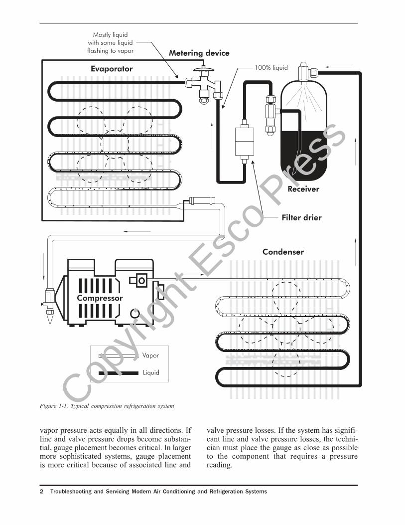
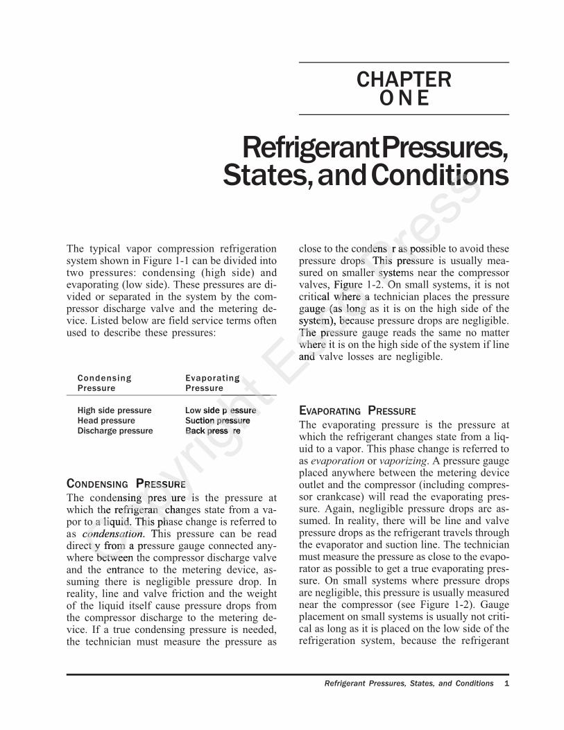
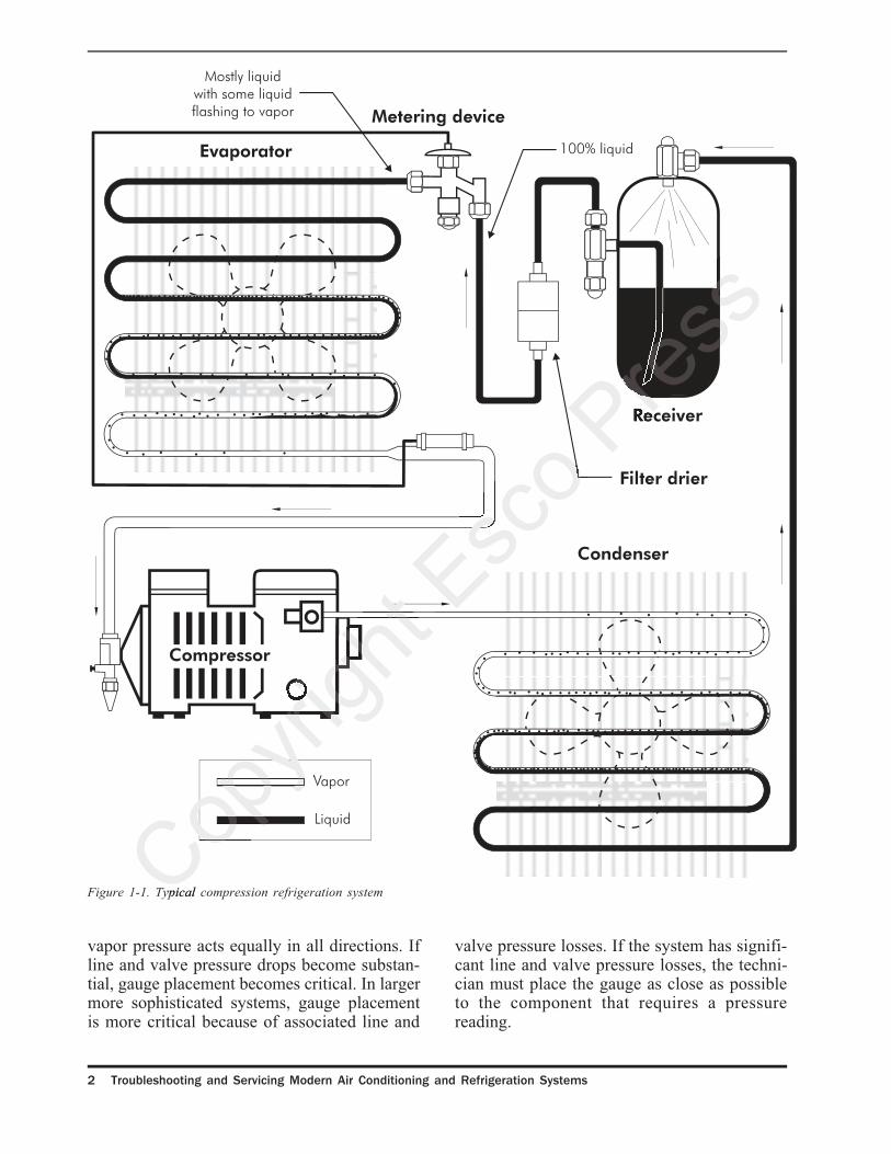
The typical vapor compression refrigerationsystem shown in Figure 1-1 can be divided intotwo pressures: condensing (high side) andevaporating (low side). These pressures are di-vided or separated in the system by the com-pressor discharge valve and the metering de-vice. Listed below are field service terms oftenused to describe these pressures:
Condensing EvaporatingPressure Pressure
High side pressure Low side p essureHead pressure Suction pressureDischarge pressure Back press re
CONDENSING PRESSURE
The condensing pres ure is the pressure atwhich the refrigeran changes state from a va-por to a liquid. This phase change is referred toas condensation. This pressure can be readdirect y from a pressure gauge connected any-where between the compressor discharge valveand the entrance to the metering device, as-suming there is negligible pressure drop. Inreality, line and valve friction and the weightof the liquid itself cause pressure drops fromthe compressor discharge to the metering de-vice. If a true condensing pressure is needed,the technician must measure the pressure as
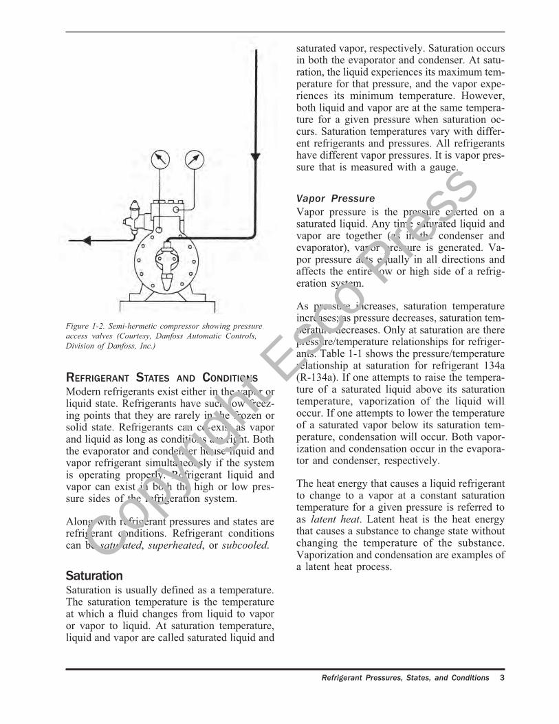
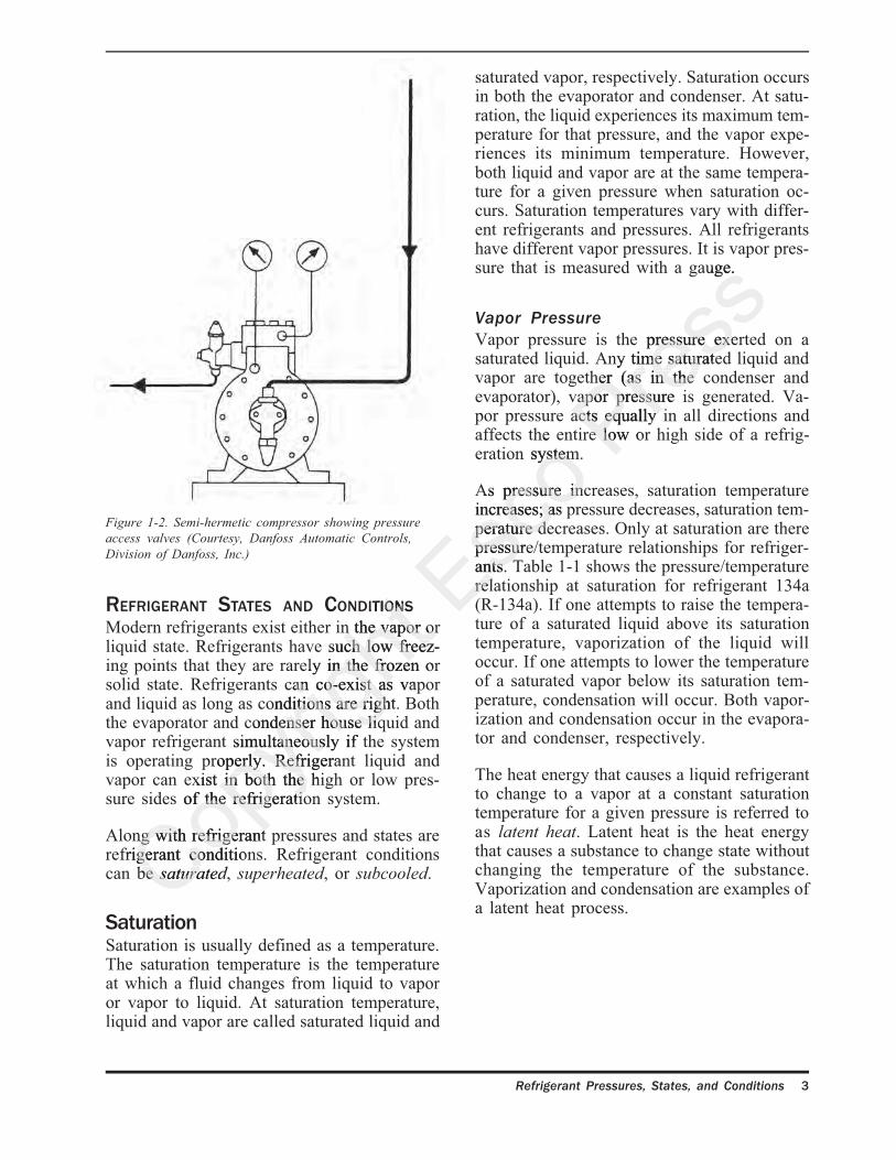
close to the condens r as possible to avoid thesepressure drops This pressure is usually mea-sured on smaller systems near the compressorvalves, Figure 1-2. On small systems, it is notcritical where a technician places the pressuregauge (as long as it is on the high side of thesystem), because pressure drops are negligible.The pressure gauge reads the same no matterwhere it is on the high side of the system if lineand valve losses are negligible.
EVAPORATING PRESSURE
The evaporating pressure is the pressure atwhich the refrigerant changes state from a liq-uid to a vapor. This phase change is referred toas evaporation or vaporizing. A pressure gaugeplaced anywhere between the metering deviceoutlet and the compressor (including compres-sor crankcase) will read the evaporating pres-sure. Again, negligible pressure drops are as-sumed. In reality, there will be line and valvepressure drops as the refrigerant travels throughthe evaporator and suction line. The technicianmust measure the pressure as close to the evapo-rator as possible to get a true evaporating pres-sure. On small systems where pressure dropsare negligible, this pressure is usually measurednear the compressor (see Figure 1-2). Gaugeplacement on small systems is usually not criti-cal as long as it is placed on the low side of therefrigeration system, because the refrigerant
Copyri
ght E
sco P
ress
2 Troubleshooting and Servicing Modern Air Conditioning and Refrigeration Systems
Figure 1-1. Typical compression refrigeration system
vapor pressure acts equally in all directions. Ifline and valve pressure drops become substan-tial, gauge placement becomes critical. In largermore sophisticated systems, gauge placementis more critical because of associated line and
valve pressure losses. If the system has signifi-cant line and valve pressure losses, the techni-cian must place the gauge as close as possibleto the component that requires a pressurereading.
Copyri
ght E
sco P
ress
Refrigerant Pressures, States, and Conditions 3
saturated vapor, respectively. Saturation occursin both the evaporator and condenser. At satu-ration, the liquid experiences its maximum tem-perature for that pressure, and the vapor expe-riences its minimum temperature. However,both liquid and vapor are at the same tempera-ture for a given pressure when saturation oc-curs. Saturation temperatures vary with differ-ent refrigerants and pressures. All refrigerantshave different vapor pressures. It is vapor pres-sure that is measured with a gauge.
Vapor Pressure
Vapor pressure is the pressure exerted on asaturated liquid. Any time saturated liquid andvapor are together (as in the condenser andevaporator), vapor pressure is generated. Va-por pressure acts equally in all directions andaffects the entire low or high side of a refrig-eration system.
As pressure increases, saturation temperatureincreases; as pressure decreases, saturation tem-perature decreases. Only at saturation are therepressure/temperature relationships for refriger-ants. Table 1-1 shows the pressure/temperaturerelationship at saturation for refrigerant 134a(R-134a). If one attempts to raise the tempera-ture of a saturated liquid above its saturationtemperature, vaporization of the liquid willoccur. If one attempts to lower the temperatureof a saturated vapor below its saturation tem-perature, condensation will occur. Both vapor-ization and condensation occur in the evapora-tor and condenser, respectively.
The heat energy that causes a liquid refrigerantto change to a vapor at a constant saturationtemperature for a given pressure is referred toas latent heat. Latent heat is the heat energythat causes a substance to change state withoutchanging the temperature of the substance.Vaporization and condensation are examples ofa latent heat process.
Figure 1-2. Semi-hermetic compressor showing pressure
access valves (Courtesy, Danfoss Automatic Controls,
Division of Danfoss, Inc.)
REFRIGERANT STATES AND CONDITIONS
Modern refrigerants exist either in the vapor orliquid state. Refrigerants have such low freez-ing points that they are rarely in the frozen orsolid state. Refrigerants can co-exist as vaporand liquid as long as conditions are right. Boththe evaporator and condenser house liquid andvapor refrigerant simultaneously if the systemis operating properly. Refrigerant liquid andvapor can exist in both the high or low pres-sure sides of the refrigeration system.
Along with refrigerant pressures and states arerefrigerant conditions. Refrigerant conditionscan be saturated, superheated, or subcooled.
SaturationSaturation is usually defined as a temperature.The saturation temperature is the temperatureat which a fluid changes from liquid to vaporor vapor to liquid. At saturation temperature,liquid and vapor are called saturated liquid and
Copyri
ght E
sco P
ress

4 Troubleshooting and Servicing Modern Air Conditioning and Refrigeration Systems
Temperature Pressure Temperature Pressure
(°F) (psig) (°F) (psig)
-10 1.8
-9 2.2
-8 2.6 30 25.6
-7 3.0 31 26.4
-6 3.5 32 27.3
-5 3.9 33 28.1
-4 4.4 34 29.0
-3 4.8 35 29.9
-2 5.3 40 34.5
-1 5.8 45 39.5
0 6.2 50 44.9
1 6.7 55 50.7
2 7.2 60 56.9
3 7.8 65 63.5
4 8.3 70 70.7
5 8.8 75 78.3
6 9.3 80 86.4
7 9.9 85 95.0
8 10.5 90 104.2
9 11.0 95 113.9
10 11.6 100 124.3
11 12.2 105 135.2
12 12.8 110 146.8
13 13.4 115 159.0
14 14.0 120 171.9
15 14.7 125 185.5
16 15.3 130 199.8
17 16.0 135 214.8
18 16.7
19 17.3
20 18.0
21 18.7
22 19.4
23 20.2
24 20.9
25 21.7
26 22.4
27 23.2
28 24.0
29 24.8
Table 1-1. R-134a saturated vapor/liquid pressure/
temperature chart
words, all of the liquid must be vaporized forsuperheating to occur; the vapor must be re-moved from contact with the vaporizing liquid.Once all the liquid has been vaporized at itssaturation temperature, any addition of heatcauses the 100% saturated vapor to start super-heating. This addition of heat causes the vaporto increase in temperature and gain sensibleheat. Sensible heat is the heat energy that causesa change in the temperature of a substance. Theheat energy that superheats vapor and increasesits temperature is sensible heat energy. Super-heating is a sensible heat process. Superheatedvapor occurs in the evaporator, suction line,and compressor.
SubcoolingSubcooling always refers to a liquid at a tem-perature below its saturation temperature for agiven pressure. Once all of the vapor changesstate to 100% saturated liquid, further removalof heat will cause the 100% liquid to drop intemperature or lose sensible heat. Subcooledliquid results. Subcooling can occur in both thecondenser and liquid line and is a sensible heatprocess. Another method of subcooling liquid,
called liquid pressure amplificationTM, is cov-ered in Chapter Two. This method increasesthe pressure on subcooled liquid, causing it tobe subcooled even more. This creates a liquidwith a temperature below its new saturationtemperature for the new higher pressure.
A thorough understanding of pressures, states,and conditions of the basic refrigeration sys-tem enables the service technician to be a goodsystematic troubleshooter. It is not until thenthat a service technician should even attemptsystematic troubleshooting.
BASIC REFRIGERATION SYSTEM
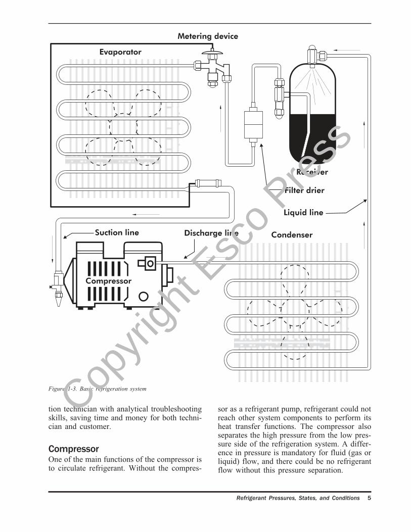
Figure 1-3 illustrates a basic refrigeration sys-tem. The basic components of this system arethe compressor, discharge line, condenser, re-ceiver, liquid line, metering device, evaporator,and suction line. Mastering the function of eachindividual component can assist the refrigera-
SuperheatSuperheat always refers to a vapor. A super-heated vapor is any vapor that is above itssaturation temperature for a given pressure. Inorder for vapor to be superheated, it must havereached its 100% saturated vapor point. In other
Copyri
ght E
sco P
ress
Refrigerant Pressures, States, and Conditions 5
Figure 1-3. Basic refrigeration system
tion technician with analytical troubleshootingskills, saving time and money for both techni-cian and customer.
CompressorOne of the main functions of the compressor isto circulate refrigerant. Without the compres-
sor as a refrigerant pump, refrigerant could notreach other system components to perform itsheat transfer functions. The compressor alsoseparates the high pressure from the low pres-sure side of the refrigeration system. A differ-ence in pressure is mandatory for fluid (gas orliquid) flow, and there could be no refrigerantflow without this pressure separation.
Copyri
ght E
sco P
ress

6 Troubleshooting and Servicing Modern Air Conditioning and Refrigeration Systems
Another function of the compressor is to el-evate or raise the temperature of the refrigerantvapor above the ambient (surrounding) tempera-ture. This is accomplished by adding work, orheat of compression, to the refrigerant vaporduring the compression cycle. The pressure ofthe refrigerant is raised, as well as its tempera-ture. By elevating the refrigerant temperatureabove the ambient temperature, heat absorbedin the evaporator and suction line, and any heatof compression generated in the compressionstroke can be rejected to this lower temperatureambient. Most of the heat is rejected in thedischarge line and the condenser. Remember,heat flows from hot to cold, and there must bea temperature difference for any heat transferto take place. The temperature rise of the re-frigerant during the compression stroke is ameasure of the increased internal kinetic en-ergy added by the compressor.
The compressor also compresses the refriger-ant vapors, which increases vapor density. Thisincrease in density helps pack the refrigerantgas molecules together, which helps in the con-densation or liquification of the refrigerant gasmolecules in the condenser once the rightamount of heat is rejected to the ambient. Thecompression of the vapors during the compres-sion stroke is actually preparing the vapors forcondensation or liquification.
Discharge LineOne function of the discharge line is to carrythe high pressure superheated vapor from thecompressor discharge valve to the entrance ofthe condenser. The discharge line also acts asa desuperheater, cooling the superheated va-pors that the compressor has compressed andgiving that heat up to the ambient (surround-ings). These compressed vapors contain all ofthe heat that the evaporator and suction linehave absorbed, along with the heat of compres-sion of the compression stroke. Any generatedmotor winding heat may also be contained inthe discharge line refrigerant, which is why thebeginning of the discharge line is the hottestpart of the refrigeration system. On hot dayswhen the system is under a high load and mayhave a dirty condenser, the discharge line can
reach over 400°F. By desuperheating the re-frigerant, the vapors will be cooled to the satu-ration temperature of the condenser. Once thevapors reach the condensing saturation tempera-ture for that pressure, condensation of vapor toliquid will take place as more heat is lost.
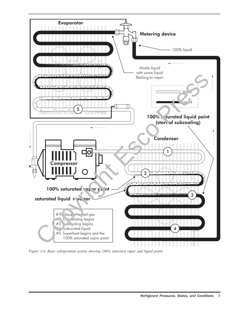
CondenserThe first passes of the condenser desuperheatthe discharge line gases. This prepares the highpressure superheated vapors coming from thedischarge line for condensation, or the phasechange from gas to liquid. Remember, thesesuperheated gases must lose all of their super-heat before reaching the condensing tempera-ture for a certain condensing pressure. Oncethe initial passes of the condenser have rejectedenough superheat and the condensing tempera-ture or saturation temperature has been reached,these gases are referred to as 100% saturatedvapor. The refrigerant is then said to havereached the 100% saturated vapor point, Figure1-4.
One of the main functions of the condenser isto condense the refrigerant vapor to liquid.Condensing is system dependent and usuallytakes place in the lower two-thirds of the con-denser. Once the saturation or condensing tem-perature is reached in the condenser and therefrigerant gas has reached 100% saturatedvapor, condensation can take place if more heatis removed. As more heat is taken away fromthe 100% saturated vapor, it will force the vaporto become a liquid or to condense. When con-densing, the vapor will gradually phase changeto liquid until 100% liquid is all that remains.This phase change, or change of state, is anexample of a latent heat rejection process, asthe heat removed is latent heat not sensible heat.The phase change will happen at one tempera-ture even though heat is being removed. Note:An exception to this is a near-azeotropic blendof refrigerants where there is a temperatureglide or range of temperatures when phasechanging (see Chapter Eight on blend tempera-ture glide). This one temperature is the satura-tion temperature corresponding to the satura-tion pressure in the condenser. As mentionedbefore, this pressure can be measured anywhere
Copyri
ght E
sco P
ress
Refrigerant Pressures, States, and Conditions 7
Figure 1-4. Basic refrigeration system showing 100% saturated vapor and liquid points
Copyri
ght E
sco P
ress
8 Troubleshooting and Servicing Modern Air Conditioning and Refrigeration Systems
on the high side of the refrigeration system aslong as line and valve pressure drops and lossesare negligible.
The last function of the condenser is to subcoolthe liquid refrigerant. Subcooling is defined asany sensible heat taken away from 100% satu-rated liquid. Technically, subcooling is definedas the difference between the measured liquidtemperature and the liquid saturation tempera-ture at a given pressure. Once the saturatedvapor in the condenser has phase changed tosaturated liquid, the 100% saturated liquid pointhas been reached. If any more heat is removed,the liquid will go through a sensible heat rejec-tion process and lose temperature as it losesheat. The liquid that is cooler than the saturatedliquid in the condenser is subcooled liquid.Subcooling is an important process, because itstarts to lower the liquid temperature to theevaporator temperature. This will reduce flashloss in the evaporator so more of the vaporiza-tion of the liquid in the evaporator can be usedfor useful cooling of the product load (seeChapter Two on the importance of liquidsubcooling).
ReceiverThe receiver acts as a surge tank. Once thesubcooled liquid exits the condenser, the re-ceiver receives and stores the liquid. The liquidlevel in the receiver varies depending onwhether the metering device is throttling openedor closed. Receivers are usually used on sys-tems in which a thermostatic expansion valve(TXV or TEV) is used as the metering device.The subcooled liquid in the receiver may loseor gain subcooling depending on the surround-ing temperature of the receiver. If the subcooledliquid is warmer than receiver surroundings, theliquid will reject heat to the surroundings andsubcool even more. If the subcooled liquid iscooler than receiver surroundings, heat will begained by the liquid and subcooling will belost.
A receiver bypass is often used to bypass liq-uid around the receiver and route it directly tothe liquid line and filter drier. This bypass pre-vents subcooled liquid from sitting in the re-
ceiver and losing its subcooling. A thermostatwith a sensing bulb on the condenser outletcontrols the bypass solenoid valve by sensingliquid temperature coming to the receiver, Fig-ure 1-5. If the liquid is subcooled to a predeter-mined temperature, it will bypass the receiverand go to the filter drier.
Liquid LineThe liquid line transports high pressuresubcooled liquid to the metering device. Intransport, the liquid may either lose or gainsubcooling depending on the surrounding tem-perature. Liquid lines may be wrapped aroundsuction lines to help them gain more subcooling,Figure 1-6. Liquid/suction line heat exchangerscan be purchased and installed in existing sys-tems to gain subcooling. The importance ofliquid subcooling will be covered more exten-sively in Chapter Two.
Metering DeviceThe metering device meters liquid refrigerantfrom the liquid line to the evaporator. Thereare several different styles and kinds of meter-ing devices on the market with different func-tions. Some metering devices control evapora-tor superheat and pressure, and some even havepressure limiting devices to protect compres-sors at heavy loads.
The metering device is a restriction that sepa-rates the high pressure side from the low pres-sure side in a refrigeration system. The com-pressor and the metering device are the twocomponents that separate pressures in a refrig-eration system. The restriction in the meteringdevice causes liquid refrigerant to flash to alower temperature in the evaporator because ofits lower pressure and temperature.
EvaporatorThe evaporator, like the condenser, acts as aheat exchanger. Heat gains from the productload and outside ambient travel through thesidewalls of the evaporator to vaporize any liq-uid refrigerant. The pressure drop through themetering device causes vaporization of some
Copyri
ght E
sco P
ress
Copyri
ght E
sco P
ress
Basic
Refrigeration and Charging Procedures
John Tomczyk
Mount Prospect, Illinois
Copyri
ght E
sco
John Tomczyk
Esco
John Tomczyk
Press

Table of Contents
Refrigerant Pressures States and Conditions
C ns n P ssur 1
Ev por n P e sur 1
R f ran St s n Cond ons 3
Vapor Pressures 3
Superheat 4
Subcooling 4
Basic Re ra ion Sys m 4
Compressor 5
Discharge Line 6
Condenser 6
Receiver 8
Liquid Line 8
Metering Device 8
Evaporator 8
Suction Line 10
Ap licati P e su s, a a Condit ns 11
Compressor Discharge 11
Condense Inlet 11
100% Satura ed Vapor Point 13
100% Saturated Liquid Point 13
Condenser Outlet 13
TXV Inlet 13
Middle of Evaporator 13
Saturated Vapor Point 14
Evaporator Outlet 14
Compressor Inlet 14
Copyri
ght
Copyri
ght
Copyri
ght
Copyri
ght
Copyri
ght
u
Copyri
ght
u
Copyri
ght
Copyri
ght
Copyri
ght
s
Copyri
ght
s
Copyri
ght
,
Copyri
ght
,
Copyri
ght
Copyri
ght
Copyri
ght
a
Copyri
ght
a
Copyri
ght
Copyri
ght
Copyri
ght
Copyri
ght
Copyri
ght
Copyri
ght
a
Copyri
ght
a
Copyri
ght
Copyri
ght
Copyri
ght
Copyri
ght
C
Copyri
ght
C
Copyri
ght
Copyri
ght
Compressor Discharge
Copyri
ght
Compressor Discharge
Copyri
ght
Condense Inlet
Copyri
ght
Condense Inlet
Copyri
ght
100% Satura ed Vapor Point
Copyri
ght
100% Satura ed Vapor Point
Copyri
ght
100% Saturated Liquid Point Copyri
ght
100% Saturated Liquid Point Copyri
ght
Condenser Outlet Copyri
ght
Condenser Outlet Copyri
ght
TXV Inlet Cop
yrigh
t
TXV Inlet
Esco
Esco
Esco
Esco
Esco
Esco Pres
sPres
sPres
sPres
sPres
sPres
sPres
sPres
sPres
sPres
sPres
s
Table of Contents
Subcooling and Superheating
Li u Su c 15
S b o lin Ca o s 15
Condenser Subcooling 15
Total Subcooling 19
S cooo N d d o Pr v n L q d L n a h 21
Pr s r Dr p 21
Friction Pressure Losses 21
Static Pressure Losses 23
How Much Su c o n s N d 24
Li u ressur Amp ic i n And Su a es o 26
Floating Head Pressures and LPA Advantages 30
Superheat Suppression 31
LPA/Superheat Suppression with Subcooling/Reheat Coil 32
Enviro a d M Re nt Con o Sy m 32
Principles of Operation 32
Determining the SPR Valve Setting 37
S p rh 38
Evaporato Superheat 38
Total Superheat 40
Metering Devices
C p ry T es 45
Sizing 46
High Heat Loads 49
Low Heat Loads 49
Service 49
Copyri
ght
Copyri
ght
Copyri
ght LPA/Superheat Suppression with Subcooling/Reheat Coil
Copyri
ght LPA/Superheat Suppression with Subcooling/Reheat Coil
Copyri
ghto
Copyri
ghto
Copyri
ghtn
Copyri
ghtn
Copyri
ght
Copyri
ght
Copyri
ghto
Copyri
ghto
Copyri
ght
Copyri
ght S
Copyri
ght S
Copyri
ghty
Copyri
ghty
Copyri
ght
Copyri
ght
Copyri
ght
Copyri
ghtm
Copyri
ghtm
Copyri
ght
Copyri
ght
Principles of Operation
Copyri
ght
Principles of Operation
Copyri
ght
Determining the SPR Valve Setting
Copyri
ght
Determining the SPR Valve Setting
Copyri
ght
Copyri
ght
Copyri
ght
Evaporato Superheat
Copyri
ght
Evaporato Superheat
Copyri
ght
Total Superheat
Copyri
ght
Total Superheat
Copyri
ght
Copyri
ght
Copyri
ght
Copyri
ght
Copyri
ght
rCopyri
ght
rCopyri
ght
yCopyri
ght
yCopyri
ght
TCopyri
ght
TCopyri
ght
Copyri
ght
Copyri
ght
eCopyri
ght
eCopyri
ght
sCopyri
ght
sCopyri
ght
Copyri
ght
Sizing Cop
yrigh
t
Sizing
Esco
Esco
Esco
Esco
Esco
Escoe
Escoe
Escos
Escos
Esco
Esco
Escoo
Escoo
Esco
Esco
Esco
Floating Head Pressures and LPA Advantages
Esco
Floating Head Pressures and LPA Advantages
Esco
Esco
Esco
LPA/Superheat Suppression with Subcooling/Reheat Coil Esco
LPA/Superheat Suppression with Subcooling/Reheat Coil
Press
Press
Press
Press
Press19
Press19
Press
Press
Press
Press
Press
Press
Press

Table of Contents
e m s a i Expa sion Valve 52
Remote Bulb Pressure 54
Evaporator Pressure and Spring Pressure 56
Additional Pressure 57
Color Codes 57
Special Application TXVs 57
Externally Equalized Valves 58
Maximum Operating Pressure 58
Balanced Port TXVs 59
Selection Procedures 59
Au omat Expansi n Va v s AXVs) 64
System Charge
C ar in TXV/ e v r/S as R f o Sy t m 67
Charging Rules 68
Char in C p ary u Or Fix d Or f R ri a io Sy em 70
Charging from a Vacuum 70
C ar ing C p ary u o x d O c A Con on ng Sy m 73
Measuring Duct Velocity 79
Superheat Charging Curves 80
Superhea Curve Theory 81
Charging Capillary Tube — Cooling Mode Only 82
Superheat Method — Capillary Tube System 85 Copyri
ght
Copyri
ght
Copyri
ght
Copyri
ghtx
Copyri
ghtx
Copyri
ght
Copyri
ghtd
Copyri
ghtd
Copyri
ght O
Copyri
ght O
Copyri
ghtr
Copyri
ghtr
Copyri
ght
Copyri
ghtf
Copyri
ghtf
Copyri
ght
Copyri
ght
Copyri
ght
Copyri
ght R
Copyri
ght R
Copyri
ght
Copyri
ght
Copyri
ghtr
Copyri
ghtr
Copyri
ght i
Copyri
ght i
Copyri
ght
Copyri
ght
Copyri
ght
Charging from a Vacuum
Copyri
ght
Charging from a Vacuum
Copyri
ght
u
Copyri
ght
u
Copyri
ght
Copyri
ght
Copyri
ght
o
Copyri
ght
o
Copyri
ght
Copyri
ght
Copyri
ght
Copyri
ght
x
Copyri
ght
x
Copyri
ght
Copyri
ght
Copyri
ght
d
Copyri
ght
d
Copyri
ght
O
Copyri
ght
O
Copyri
ght
Copyri
ght
Copyri
ght
Copyri
ght
Copyri
ght
c
Copyri
ght
c
Copyri
ght
Copyri
ght
Copyri
ght
Measuring Duct Velocity
Copyri
ght
Measuring Duct Velocity
Copyri
ght
Superheat Charging Curves
Copyri
ght
Superheat Charging Curves
Copyri
ght
Superhea Curve Theory
Copyri
ght
Superhea Curve Theory
Copyri
ght
Charging Capillary Tube — Cooling Mode Only Copyri
ght
Charging Capillary Tube — Cooling Mode Only Copyri
ght
Copyri
ght
Copyri
ght
Superheat Method — Capillary Tube System Copyri
ght
Superheat Method — Capillary Tube System
Esco
Esco
Esco
Esco
System Charge
Esco
System Charge
Esco
Esco
Esco
Esco
Esco
Esco
Esco
Esco
oEsco
oEsco
Esco
SEsco
SEsco
yEsco
yEsco
Esco
tEsco
tEsco Pres
sPres
sPres
sPres
sPres
s57
Press57
Press
Press
Press
Press
Press
Press
Press

Copyri
ght E
sco Pres
s
Refrigerant Pressures, States, and Conditions 1
Refrigerant Pressures,States, and Conditions
CHAPTERO N E
The typical vapor compression refrigerationsystem shown in Figure 1-1 can be divided intotwo pressures: condensing (high side) andevaporating (low side). These pressures are di-vided or separated in the system by the com-pressor discharge valve and the metering de-vice. Listed below are field service terms oftenused to describe these pressures:
Condensing EvaporatingPressure Pressure
High side pressure Low side p essureHead pressure Suction pressureDischarge pressure Back press re
CONDENSING PRESSURE
The condensing pres ure is the pressure atwhich the refrigeran changes state from a va-por to a liquid. This phase change is referred toas condensation. This pressure can be readdirect y from a pressure gauge connected any-where between the compressor discharge valveand the entrance to the metering device, as-suming there is negligible pressure drop. Inreality, line and valve friction and the weightof the liquid itself cause pressure drops fromthe compressor discharge to the metering de-vice. If a true condensing pressure is needed,the technician must measure the pressure as
close to the condens r as possible to avoid thesepressure drops This pressure is usually mea-sured on smaller systems near the compressorvalves, Figure 1-2. On small systems, it is notcritical where a technician places the pressuregauge (as long as it is on the high side of thesystem), because pressure drops are negligible.The pressure gauge reads the same no matterwhere it is on the high side of the system if lineand valve losses are negligible.
EVAPORATING PRESSURE
The evaporating pressure is the pressure atwhich the refrigerant changes state from a liq-uid to a vapor. This phase change is referred toas evaporation or vaporizing. A pressure gaugeplaced anywhere between the metering deviceoutlet and the compressor (including compres-sor crankcase) will read the evaporating pres-sure. Again, negligible pressure drops are as-sumed. In reality, there will be line and valvepressure drops as the refrigerant travels throughthe evaporator and suction line. The technicianmust measure the pressure as close to the evapo-rator as possible to get a true evaporating pres-sure. On small systems where pressure dropsare negligible, this pressure is usually measurednear the compressor (see Figure 1-2). Gaugeplacement on small systems is usually not criti-cal as long as it is placed on the low side of therefrigeration system, because the refrigerant
Copyri
ghtEvaporating
Copyri
ghtEvaporating
Copyri
ghtHigh side pressure Low side p essure
Copyri
ghtHigh side pressure Low side p essure
Suction pressure
Copyri
ght
Suction pressureDischarge pressure Back press re
Copyri
ght
Discharge pressure Back press re
P
Copyri
ght
PRES
Copyri
ght
RESSURE
Copyri
ght
SURE
The condensing pres ure is the pressure at
Copyri
ght
The condensing pres ure is the pressure atwhich the refrigeran changes state from a va-
Copyri
ght
which the refrigeran changes state from a va-por to a liquid. This phase change is referred to
Copyri
ght
por to a liquid. This phase change is referred tocondensationCop
yrigh
t
condensationCopyri
ght
. This pressure can be readCopyri
ght
. This pressure can be readdirect y from a pressure gauge connected any-Cop
yrigh
t
direct y from a pressure gauge connected any-where between the compressor discharge valveCop
yrigh
t
where between the compressor discharge valveand the entrance to the metering device, as-Cop
yrigh
t
and the entrance to the metering device, as-
Esco
sured on smaller systems near the compressor
Esco
sured on smaller systems near the compressorvalves, Figure 1-2. On small systems, it is not
Escovalves, Figure 1-2. On small systems, it is not
Escocritical where a technician places the pressure
Escocritical where a technician places the pressure
gauge (as long as it is on the high side of the
Escogauge (as long as it is on the high side of the
system), because pressure drops are negligible.
Escosystem), because pressure drops are negligible.
The pressure gauge reads the same no matter
Esco
The pressure gauge reads the same no matterwhere it is on the high side of the system if line
Esco
where it is on the high side of the system if lineand valve losses are negligible.Esc
oand valve losses are negligible.
Press
Refrigerant Pressures,
Press
Refrigerant Pressures,es, and Conditions
Presses, and Conditions
Press
close to the condens r as possible to avoid these
Press
close to the condens r as possible to avoid thesepressure drops This pressure is usually mea-Pres
spressure drops This pressure is usually mea-sured on smaller systems near the compressorPres
ssured on smaller systems near the compressorvalves, Figure 1-2. On small systems, it is notPres
svalves, Figure 1-2. On small systems, it is not
2 Troubleshooting and Servicing Modern Air Conditioning and Refrigeration Systems
Figure 1-1. Typical compression refrigeration system
vapor pressure acts equally in all directions. Ifline and valve pressure drops become substan-tial, gauge placement becomes critical. In largermore sophisticated systems, gauge placementis more critical because of associated line and
valve pressure losses. If the system has signifi-cant line and valve pressure losses, the techni-cian must place the gauge as close as possibleto the component that requires a pressurereading.
Copyri
ght
Copyri
ght
Copyri
ght
Copyri
ght
Copyri
ght
Copyri
ght
Copyri
ght
Copyri
ght
Copyri
ght
Copyri
ght
Copyri
ght
Copyri
ght
Copyri
ght
Copyri
ght
Copyri
ght
Copyri
ght
Copyri
ght
Copyri
ght
Copyri
ght
Copyri
ght
Copyri
ght
Copyri
ght
Figure 1-1. Typical compression refrigeration systemCopyri
ght
Figure 1-1. Typical compression refrigeration system
Esco
Esco
Esco
Esco Pres
sPres
sPres
sPres
sPres
sPres
sPres
sPres
s
Refrigerant Pressures, States, and Conditions 3
saturated vapor, respectively. Saturation occursin both the evaporator and condenser. At satu-ration, the liquid experiences its maximum tem-perature for that pressure, and the vapor expe-riences its minimum temperature. However,both liquid and vapor are at the same tempera-ture for a given pressure when saturation oc-curs. Saturation temperatures vary with differ-ent refrigerants and pressures. All refrigerantshave different vapor pressures. It is vapor pres-sure that is measured with a gauge.
Vapor Pressure
Vapor pressure is the pressure exerted on asaturated liquid. Any time saturated liquid andvapor are together (as in the condenser andevaporator), vapor pressure is generated. Va-por pressure acts equally in all directions andaffects the entire low or high side of a refrig-eration system.
As pressure increases, saturation temperatureincreases; as pressure decreases, saturation tem-perature decreases. Only at saturation are therepressure/temperature relationships for refriger-ants. Table 1-1 shows the pressure/temperaturerelationship at saturation for refrigerant 134a(R-134a). If one attempts to raise the tempera-ture of a saturated liquid above its saturationtemperature, vaporization of the liquid willoccur. If one attempts to lower the temperatureof a saturated vapor below its saturation tem-perature, condensation will occur. Both vapor-ization and condensation occur in the evapora-tor and condenser, respectively.
The heat energy that causes a liquid refrigerantto change to a vapor at a constant saturationtemperature for a given pressure is referred toas latent heat. Latent heat is the heat energythat causes a substance to change state withoutchanging the temperature of the substance.Vaporization and condensation are examples ofa latent heat process.
Figure 1-2. Semi-hermetic compressor showing pressure
access valves (Courtesy, Danfoss Automatic Controls,
Division of Danfoss, Inc.)
REFRIGERANT STATES AND CONDITIONS
Modern refrigerants exist either in the vapor orliquid state. Refrigerants have such low freez-ing points that they are rarely in the frozen orsolid state. Refrigerants can co-exist as vaporand liquid as long as conditions are right. Boththe evaporator and condenser house liquid andvapor refrigerant simultaneously if the systemis operating properly. Refrigerant liquid andvapor can exist in both the high or low pres-sure sides of the refrigeration system.
Along with refrigerant pressures and states arerefrigerant conditions. Refrigerant conditionscan be saturated, superheated, or subcooled.
SaturationSaturation is usually defined as a temperature.The saturation temperature is the temperatureat which a fluid changes from liquid to vaporor vapor to liquid. At saturation temperature,liquid and vapor are called saturated liquid and
Copyri
ghtONDITIONS
Copyri
ghtONDITIONS
Modern refrigerants exist either in the vapor or
Copyri
ghtModern refrigerants exist either in the vapor or
liquid state. Refrigerants have such low freez-
Copyri
ghtliquid state. Refrigerants have such low freez-
ing points that they are rarely in the frozen or
Copyri
ght
ing points that they are rarely in the frozen orsolid state. Refrigerants can co-exist as vapor
Copyri
ght
solid state. Refrigerants can co-exist as vaporand liquid as long as conditions are right. Both
Copyri
ght
and liquid as long as conditions are right. Boththe evaporator and condenser house liquid and
Copyri
ght
the evaporator and condenser house liquid andvapor refrigerant simultaneously if the system
Copyri
ght
vapor refrigerant simultaneously if the system
Copyri
ght
is operating properly. Refrigerant liquid and
Copyri
ght
is operating properly. Refrigerant liquid andvapor can exist in both the high or low pres-
Copyri
ght
vapor can exist in both the high or low pres-sure sides of the refrigeration system.
Copyri
ght
sure sides of the refrigeration system.
Along with refrigerant pressures and states are
Copyri
ght
Along with refrigerant pressures and states are
Copyri
ght
refrigerant conditions. Refrigerant conditionsCopyri
ght
refrigerant conditions. Refrigerant conditionscan be Cop
yrigh
t
can be saturatedCopyri
ght
saturated
Esco
affects the entire low or high side of a refrig-
Esco
affects the entire low or high side of a refrig-eration system.
Escoeration system.
As pressure increases, saturation temperature
EscoAs pressure increases, saturation temperature
increases; as pressure decreases, saturation tem-
Escoincreases; as pressure decreases, saturation tem-
perature decreases. Only at saturation are there
Esco
perature decreases. Only at saturation are therepressure/temperature relationships for refriger-
Esco
pressure/temperature relationships for refriger-ants. Table 1-1 shows the pressure/temperatureEsc
oants. Table 1-1 shows the pressure/temperaturerelationship at saturation for refrigerant 134aEsc
orelationship at saturation for refrigerant 134a
Press
have different vapor pressures. It is vapor pres-
Press
have different vapor pressures. It is vapor pres-sure that is measured with a gauge.
Presssure that is measured with a gauge.
Vapor pressure is the pressure exerted on a
Press
Vapor pressure is the pressure exerted on asaturated liquid. Any time saturated liquid and
Press
saturated liquid. Any time saturated liquid andvapor are together (as in the condenser and
Press
vapor are together (as in the condenser andevaporator), vapor pressure is generated. Va-Pres
sevaporator), vapor pressure is generated. Va-por pressure acts equally in all directions andPres
spor pressure acts equally in all directions andaffects the entire low or high side of a refrig-Pres
saffects the entire low or high side of a refrig-

4 Troubleshooting and Servicing Modern Air Conditioning and Refrigeration Systems
Temperature Pressure Temperature Pressure
(°F) (psig) (°F) (psig)
-10 1.8
-9 2.2
-8 2.6 30 25.6
-7 3.0 31 26.4
-6 3.5 32 27.3
-5 3.9 33 28.1
-4 4.4 34 29.0
-3 4.8 35 29.9
-2 5.3 40 34.5
-1 5.8 45 39.5
0 6.2 50 44.9
1 6.7 55 50.7
2 7.2 60 56.9
3 7.8 65 63.5
4 8.3 70 70.7
5 8.8 75 78.3
6 9.3 80 86.4
7 9.9 85 95.0
8 10.5 90 104.2
9 11.0 95 113.9
10 11.6 100 124.3
11 12.2 105 135.2
12 12.8 110 146.8
13 13.4 115 159.0
14 14.0 120 171.9
15 14.7 125 185.5
16 15.3 130 199.8
17 16.0 135 214.8
18 16.7
19 17.3
20 18.0
21 18.7
22 19.4
23 20.2
24 20.9
25 21.7
26 22.4
27 23.2
28 24.0
29 24.8
Table 1-1. R-134a saturated vapor/liquid pressure/
temperature chart
words, all of the liquid must be vaporized forsuperheating to occur; the vapor must be re-moved from contact with the vaporizing liquid.Once all the liquid has been vaporized at itssaturation temperature, any addition of heatcauses the 100% saturated vapor to start super-heating. This addition of heat causes the vaporto increase in temperature and gain sensibleheat. Sensible heat is the heat energy that causesa change in the temperature of a substance. Theheat energy that superheats vapor and increasesits temperature is sensible heat energy. Super-heating is a sensible heat process. Superheatedvapor occurs in the evaporator, suction line,and compressor.
SubcoolingSubcooling always refers to a liquid at a tem-perature below its saturation temperature for agiven pressure. Once all of the vapor changesstate to 100% saturated liquid, further removalof heat will cause the 100% liquid to drop intemperature or lose sensible heat. Subcooledliquid results. Subcooling can occur in both thecondenser and liquid line and is a sensible heatprocess. Another method of subcooling liquid,
called liquid pressure amplificationTM, is cov-ered in Chapter Two. This method increasesthe pressure on subcooled liquid, causing it tobe subcooled even more. This creates a liquidwith a temperature below its new saturationtemperature for the new higher pressure.
A thorough understanding of pressures, states,and conditions of the basic refrigeration sys-tem enables the service technician to be a goodsystematic troubleshooter. It is not until thenthat a service technician should even attemptsystematic troubleshooting.
BASIC REFRIGERATION SYSTEM
Figure 1-3 illustrates a basic refrigeration sys-tem. The basic components of this system arethe compressor, discharge line, condenser, re-ceiver, liquid line, metering device, evaporator,and suction line. Mastering the function of eachindividual component can assist the refrigera-
SuperheatSuperheat always refers to a vapor. A super-heated vapor is any vapor that is above itssaturation temperature for a given pressure. Inorder for vapor to be superheated, it must havereached its 100% saturated vapor point. In other
Copyri
ght
Copyri
ght
Copyri
ght135 214.8
Copyri
ght135 214.8
Copyri
ght
Copyri
ght
Copyri
ght
Copyri
ght
Copyri
ght
Copyri
ght
Copyri
ght
Copyri
ght
Copyri
ght
26 22.4
Copyri
ght
26 22.4
Copyri
ght
27 23.2
Copyri
ght
27 23.2
Copyri
ght
28 24.0
Copyri
ght
28 24.0
29 24.8
Copyri
ght
29 24.8
Copyri
ght
Copyri
ght
Table 1-1. R-134a saturated vapor/liquid pressure/Copyri
ght
Table 1-1. R-134a saturated vapor/liquid pressure/
temperature chartCopyri
ght
temperature chart
Esco
Esco
Esco
perature below its saturation temperature for a
Esco
perature below its saturation temperature for agiven pressure. Once all of the vapor changes
Escogiven pressure. Once all of the vapor changes
state to 100% saturated liquid, further removal
Escostate to 100% saturated liquid, further removal
of heat will cause the 100% liquid to drop in
Escoof heat will cause the 100% liquid to drop in
temperature or lose sensible heat. Subcooled
Escotemperature or lose sensible heat. Subcooled
liquid results. Subcooling can occur in both the
Esco
liquid results. Subcooling can occur in both thecondenser and liquid line and is a sensible heat
Esco
condenser and liquid line and is a sensible heatprocess. Another method of subcooling liquid,Esc
oprocess. Another method of subcooling liquid,
called liquid pressure amplificationEsco
called liquid pressure amplificationered in Esc
oered in
Press
a change in the temperature of a substance. The
Press
a change in the temperature of a substance. Theheat energy that superheats vapor and increases
Pressheat energy that superheats vapor and increases
its temperature is sensible heat energy. Super-
Pressits temperature is sensible heat energy. Super-
heating is a sensible heat process. Superheated
Pressheating is a sensible heat process. Superheated
vapor occurs in the evaporator, suction line,
Pressvapor occurs in the evaporator, suction line,
Subcooling always refers to a liquid at a tem-Press
Subcooling always refers to a liquid at a tem-perature below its saturation temperature for aPres
sperature below its saturation temperature for agiven pressure. Once all of the vapor changesPres
sgiven pressure. Once all of the vapor changes

Refrigerant Pressures, States, and Conditions 5
Figure 1-3. Basic refrigeration system
tion technician with analytical troubleshootingskills, saving time and money for both techni-cian and customer.
CompressorOne of the main functions of the compressor isto circulate refrigerant. Without the compres-
sor as a refrigerant pump, refrigerant could notreach other system components to perform itsheat transfer functions. The compressor alsoseparates the high pressure from the low pres-sure side of the refrigeration system. A differ-ence in pressure is mandatory for fluid (gas orliquid) flow, and there could be no refrigerantflow without this pressure separation.
Copyri
ght
Figure 1-3. Basic refrigeration systemCopyri
ght
Figure 1-3. Basic refrigeration systemCopyri
ght
Copyri
ght
Copyri
ght
Copyri
ght
Copyri
ght
Copyri
ght
Copyri
ght
Copyri
ght
tion technician with analytical troubleshootingCopyri
ght
tion technician with analytical troubleshootingskills, saving time and money for both techni-
Copyri
ght
skills, saving time and money for both techni-
Esco
Esco
Esco
Esco
Esco
Esco
Esco
Esco
Esco
Esco
Esco
Esco
Esco
Esco Pres
sPres
sPres
sPres
sPres
sPres
sPres
sPres
sPres
sPres
sPres
sPres
sPres
sPres
sPres
sPres
sPres
sPres
s
6 Troubleshooting and Servicing Modern Air Conditioning and Refrigeration Systems
Another function of the compressor is to el-evate or raise the temperature of the refrigerantvapor above the ambient (surrounding) tempera-ture. This is accomplished by adding work, orheat of compression, to the refrigerant vaporduring the compression cycle. The pressure ofthe refrigerant is raised, as well as its tempera-ture. By elevating the refrigerant temperatureabove the ambient temperature, heat absorbedin the evaporator and suction line, and any heatof compression generated in the compressionstroke can be rejected to this lower temperatureambient. Most of the heat is rejected in thedischarge line and the condenser. Remember,heat flows from hot to cold, and there must bea temperature difference for any heat transferto take place. The temperature rise of the re-frigerant during the compression stroke is ameasure of the increased internal kinetic en-ergy added by the compressor.
The compressor also compresses the refriger-ant vapors, which increases vapor density. Thisincrease in density helps pack the refrigerantgas molecules together, which helps in the con-densation or liquification of the refrigerant gasmolecules in the condenser once the rightamount of heat is rejected to the ambient. Thecompression of the vapors during the compres-sion stroke is actually preparing the vapors forcondensation or liquification.
Discharge LineOne function of the discharge line is to carrythe high pressure superheated vapor from thecompressor discharge valve to the entrance ofthe condenser. The discharge line also acts asa desuperheater, cooling the superheated va-pors that the compressor has compressed andgiving that heat up to the ambient (surround-ings). These compressed vapors contain all ofthe heat that the evaporator and suction linehave absorbed, along with the heat of compres-sion of the compression stroke. Any generatedmotor winding heat may also be contained inthe discharge line refrigerant, which is why thebeginning of the discharge line is the hottestpart of the refrigeration system. On hot dayswhen the system is under a high load and mayhave a dirty condenser, the discharge line can
reach over 400°F. By desuperheating the re-frigerant, the vapors will be cooled to the satu-ration temperature of the condenser. Once thevapors reach the condensing saturation tempera-ture for that pressure, condensation of vapor toliquid will take place as more heat is lost.
CondenserThe first passes of the condenser desuperheatthe discharge line gases. This prepares the highpressure superheated vapors coming from thedischarge line for condensation, or the phasechange from gas to liquid. Remember, thesesuperheated gases must lose all of their super-heat before reaching the condensing tempera-ture for a certain condensing pressure. Oncethe initial passes of the condenser have rejectedenough superheat and the condensing tempera-ture or saturation temperature has been reached,these gases are referred to as 100% saturatedvapor. The refrigerant is then said to havereached the 100% saturated vapor point, Figure1-4.
One of the main functions of the condenser isto condense the refrigerant vapor to liquid.Condensing is system dependent and usuallytakes place in the lower two-thirds of the con-denser. Once the saturation or condensing tem-perature is reached in the condenser and therefrigerant gas has reached 100% saturatedvapor, condensation can take place if more heatis removed. As more heat is taken away fromthe 100% saturated vapor, it will force the vaporto become a liquid or to condense. When con-densing, the vapor will gradually phase changeto liquid until 100% liquid is all that remains.This phase change, or change of state, is anexample of a latent heat rejection process, asthe heat removed is latent heat not sensible heat.The phase change will happen at one tempera-ture even though heat is being removed. Note:An exception to this is a near-azeotropic blendof refrigerants where there is a temperatureglide or range of temperatures when phasechanging (see Chapter Eight on blend tempera-ture glide). This one temperature is the satura-tion temperature corresponding to the satura-tion pressure in the condenser. As mentionedbefore, this pressure can be measured anywhere
Copyri
ghtamount of heat is rejected to the ambient. The
Copyri
ghtamount of heat is rejected to the ambient. The
compression of the vapors during the compres-
Copyri
ghtcompression of the vapors during the compres-
sion stroke is actually preparing the vapors for
Copyri
ghtsion stroke is actually preparing the vapors for
One function of the discharge line is to carry
Copyri
ght
One function of the discharge line is to carrythe high pressure superheated vapor from the
Copyri
ght
the high pressure superheated vapor from thecompressor discharge valve to the entrance of
Copyri
ght
compressor discharge valve to the entrance ofthe condenser. The discharge line also acts as
Copyri
ght
the condenser. The discharge line also acts asa desuperheater, cooling the superheated va-
Copyri
ght
a desuperheater, cooling the superheated va-pors that the compressor has compressed and
Copyri
ght
pors that the compressor has compressed andgiving that heat up to the ambient (surround-
Copyri
ght
giving that heat up to the ambient (surround-ings). These compressed vapors contain all ofCop
yrigh
t
ings). These compressed vapors contain all ofthe heat that the evaporator and suction lineCop
yrigh
t
the heat that the evaporator and suction linehave absorbed, along with the heat of compres-Cop
yrigh
t
have absorbed, along with the heat of compres-sion of the compression stroke. Any generated
Copyri
ght
sion of the compression stroke. Any generated
Esco
densation or liquification of the refrigerant gas
Esco
densation or liquification of the refrigerant gasmolecules in the condenser once the right Esc
omolecules in the condenser once the right
ture or saturation temperature has been reached,
Esco
ture or saturation temperature has been reached,these gases are referred to as 100% saturated
Escothese gases are referred to as 100% saturated
vapor. The refrigerant is then said to have
Escovapor. The refrigerant is then said to have
reached the 100% saturated vapor point, Figure
Escoreached the 100% saturated vapor point, Figure
1-4.
Esco1-4.
One of the main functions of the condenser is
Esco
One of the main functions of the condenser isto condense the refrigerant vapor to liquid.Esc
oto condense the refrigerant vapor to liquid.Condensing is system dependent and usuallyEsc
oCondensing is system dependent and usuallytakes place in the lower two-thirds of the con-Esc
otakes place in the lower two-thirds of the con-
Press
the discharge line gases. This prepares the high
Press
the discharge line gases. This prepares the highpressure superheated vapors coming from the
Presspressure superheated vapors coming from the
discharge line for condensation, or the phase
Pressdischarge line for condensation, or the phase
change from gas to liquid. Remember, these
Presschange from gas to liquid. Remember, these
superheated gases must lose all of their super-
Press
superheated gases must lose all of their super-heat before reaching the condensing tempera-
Press
heat before reaching the condensing tempera-ture for a certain condensing pressure. Once
Press
ture for a certain condensing pressure. Oncethe initial passes of the condenser have rejectedPres
sthe initial passes of the condenser have rejectedenough superheat and the condensing tempera-Pres
senough superheat and the condensing tempera-ture or saturation temperature has been reached,Pres
sture or saturation temperature has been reached,these gases are referred to as 100% saturatedPres
sthese gases are referred to as 100% saturated

Refrigerant Pressures, States, and Conditions 7
Figure 1-4. Basic refrigeration system showing 100% saturated vapor and liquid points
Copyri
ght
Copyri
ght
Copyri
ght
Copyri
ght
Copyri
ght
Copyri
ght
Copyri
ght
Copyri
ght
Copyri
ght
Copyri
ght
Copyri
ght
Copyri
ght
Copyri
ght
Copyri
ght
Copyri
ght
Copyri
ght
Copyri
ght
Copyri
ght
Copyri
ght
Copyri
ght
Copyri
ght
Copyri
ght
Copyri
ght
Copyri
ght
Copyri
ght
Copyri
ght
Copyri
ght
Copyri
ght
Copyri
ght
Copyri
ght
Copyri
ght
Copyri
ght
Copyri
ght
Copyri
ght
Copyri
ght
Copyri
ght
Copyri
ght
Copyri
ght
Copyri
ght
Copyri
ght
Copyri
ght
Copyri
ght
Copyri
ght
Copyri
ght
Copyri
ght
Copyri
ght
Copyri
ght
Copyri
ght
Copyri
ght
Copyri
ght
Copyri
ght
Copyri
ght
Copyri
ght
Copyri
ght
Copyri
ght
Copyri
ght
Copyri
ght
Copyri
ght
Copyri
ght
Copyri
ght
Copyri
ght
Copyri
ght
Copyri
ght
Copyri
ght
Copyri
ght
Copyri
ght
Copyri
ght
Copyri
ght
Copyri
ght
Copyri
ght
Copyri
ght E
sco
Esco
Esco
Esco
Esco
Esco
Esco Pres
sPres
sPres
sPres
sPres
sPres
sPres
sPres
sPres
sPres
sPres
sPres
sPres
sPres
sPres
sPres
sPres
sPres
sPres
sPres
sPres
sPres
sPres
sPres
sPres
sPres
sPres
s

8 Troubleshooting and Servicing Modern Air Conditioning and Refrigeration Systems
on the high side of the refrigeration system aslong as line and valve pressure drops and lossesare negligible.
The last function of the condenser is to subcoolthe liquid refrigerant. Subcooling is defined asany sensible heat taken away from 100% satu-rated liquid. Technically, subcooling is definedas the difference between the measured liquidtemperature and the liquid saturation tempera-ture at a given pressure. Once the saturatedvapor in the condenser has phase changed tosaturated liquid, the 100% saturated liquid pointhas been reached. If any more heat is removed,the liquid will go through a sensible heat rejec-tion process and lose temperature as it losesheat. The liquid that is cooler than the saturatedliquid in the condenser is subcooled liquid.Subcooling is an important process, because itstarts to lower the liquid temperature to theevaporator temperature. This will reduce flashloss in the evaporator so more of the vaporiza-tion of the liquid in the evaporator can be usedfor useful cooling of the product load (seeChapter Two on the importance of liquidsubcooling).
ReceiverThe receiver acts as a surge tank. Once thesubcooled liquid exits the condenser, the re-ceiver receives and stores the liquid. The liquidlevel in the receiver varies depending onwhether the metering device is throttling openedor closed. Receivers are usually used on sys-tems in which a thermostatic expansion valve(TXV or TEV) is used as the metering device.The subcooled liquid in the receiver may loseor gain subcooling depending on the surround-ing temperature of the receiver. If the subcooledliquid is warmer than receiver surroundings, theliquid will reject heat to the surroundings andsubcool even more. If the subcooled liquid iscooler than receiver surroundings, heat will begained by the liquid and subcooling will belost.
A receiver bypass is often used to bypass liq-uid around the receiver and route it directly tothe liquid line and filter drier. This bypass pre-vents subcooled liquid from sitting in the re-
ceiver and losing its subcooling. A thermostatwith a sensing bulb on the condenser outletcontrols the bypass solenoid valve by sensingliquid temperature coming to the receiver, Fig-ure 1-5. If the liquid is subcooled to a predeter-mined temperature, it will bypass the receiverand go to the filter drier.
Liquid LineThe liquid line transports high pressuresubcooled liquid to the metering device. Intransport, the liquid may either lose or gainsubcooling depending on the surrounding tem-perature. Liquid lines may be wrapped aroundsuction lines to help them gain more subcooling,Figure 1-6. Liquid/suction line heat exchangerscan be purchased and installed in existing sys-tems to gain subcooling. The importance ofliquid subcooling will be covered more exten-sively in Chapter Two.
Metering DeviceThe metering device meters liquid refrigerantfrom the liquid line to the evaporator. Thereare several different styles and kinds of meter-ing devices on the market with different func-tions. Some metering devices control evapora-tor superheat and pressure, and some even havepressure limiting devices to protect compres-sors at heavy loads.
The metering device is a restriction that sepa-rates the high pressure side from the low pres-sure side in a refrigeration system. The com-pressor and the metering device are the twocomponents that separate pressures in a refrig-eration system. The restriction in the meteringdevice causes liquid refrigerant to flash to alower temperature in the evaporator because ofits lower pressure and temperature.
EvaporatorThe evaporator, like the condenser, acts as aheat exchanger. Heat gains from the productload and outside ambient travel through thesidewalls of the evaporator to vaporize any liq-uid refrigerant. The pressure drop through themetering device causes vaporization of some
Copyri
ghtThe receiver acts as a surge tank. Once the
Copyri
ghtThe receiver acts as a surge tank. Once the
subcooled liquid exits the condenser, the re-
Copyri
ghtsubcooled liquid exits the condenser, the re-
ceiver receives and stores the liquid. The liquid
Copyri
ght
ceiver receives and stores the liquid. The liquidlevel in the receiver varies depending on
Copyri
ght
level in the receiver varies depending onwhether the metering device is throttling opened
Copyri
ght
whether the metering device is throttling openedor closed. Receivers are usually used on sys-
Copyri
ght
or closed. Receivers are usually used on sys-tems in which a thermostatic expansion valve
Copyri
ght
tems in which a thermostatic expansion valve(TXV or TEV) is used as the metering device.
Copyri
ght
(TXV or TEV) is used as the metering device.The subcooled liquid in the receiver may lose
Copyri
ght
The subcooled liquid in the receiver may loseor gain subcooling depending on the surround-
Copyri
ght
or gain subcooling depending on the surround-ing temperature of the receiver. If the subcooled
Copyri
ght
ing temperature of the receiver. If the subcooledliquid is warmer than receiver surroundings, the
Copyri
ght
liquid is warmer than receiver surroundings, theliquid will reject heat to the surroundings andCop
yrigh
t
liquid will reject heat to the surroundings andsubcool even more. If the subcooled liquid isCop
yrigh
t
subcool even more. If the subcooled liquid iscooler than receiver surroundings, heat will beCop
yrigh
t
cooler than receiver surroundings, heat will begained by the liquid and subcooling will be
Copyri
ght
gained by the liquid and subcooling will be
Esco
liquid subcooling will be covered more exten-
Esco
liquid subcooling will be covered more exten-sively in Chapter Two.
Escosively in Chapter Two.
Metering Device
EscoMetering Device
The metering device meters liquid refrigerant
Esco
The metering device meters liquid refrigerantfrom the liquid line to the evaporator. There
Esco
from the liquid line to the evaporator. Thereare several different styles and kinds of meter-Esc
oare several different styles and kinds of meter-ing devices on the market with different func-Esc
oing devices on the market with different func-Esc
otions. Some metering devices control evapora-Esc
otions. Some metering devices control evapora-
Press
The liquid line transports high pressure
Press
The liquid line transports high pressuresubcooled liquid to the metering device. In
Presssubcooled liquid to the metering device. In
transport, the liquid may either lose or gain
Presstransport, the liquid may either lose or gain
subcooling depending on the surrounding tem-
Presssubcooling depending on the surrounding tem-
perature. Liquid lines may be wrapped around
Press
perature. Liquid lines may be wrapped aroundsuction lines to help them gain more subcooling,
Press
suction lines to help them gain more subcooling,Figure 1-6. Liquid/suction line heat exchangers
Press
Figure 1-6. Liquid/suction line heat exchangerscan be purchased and installed in existing sys-Pres
scan be purchased and installed in existing sys-tems to gain subcooling. The importance ofPres
stems to gain subcooling. The importance ofliquid subcooling will be covered more exten-Pres
sliquid subcooling will be covered more exten-sively in Chapter Two.Pres
ssively in Chapter Two.

Copyri
ght E
sco Pres
s