pressure control engineering coiled tubing technology ... · the pce coiled tubing cement valve is...
TRANSCRIPT

Pressure ControlEngineering
Coiled TubingTechnology Catalogue
Version 1.0
© Pressure Control Engineering 1998
Pressure ControlEngineering
Coiled TubingTechnology Catalogue
Version 1.0
© Pressure Control Engineering 1998
Pressure Control EngineeringHolton Road, Holton Heath Trading Estate, Poole, Dorset, BH16 6LT. United KingdomTel: +44 (0)1202 631817 Fax: +44 (0)1202 631708 E-Mail: [email protected]
CO
ILE
D T
UB
ING
PR
OD
UC
TS
MAIN MENUMAIN MENUMAIN MENUMAIN MENUMAIN MENU

Pressure Control EngineeringHolton Road, Holton Heath Trading Estate, Poole, Dorset, BH16 6LT. United KingdomTel: +44 (0)1202 631817 Fax: +44 (0)1202 631708 E-Mail: [email protected]
CO
ILE
D T
UB
ING
PR
OD
UC
TSAccelerators
DOWNSTROKE ACCELERATOR .............................
UPSTROKE ACCELERATOR ....................................
CentralisersFLUTED CENTRALISER ..........................................
Circulation ValvesBALL ACTIVATED CIRCULATION VALVE ................
BURST DISC CIRCULATION SUB ............................
ConnectorsC.A.R.S.A.C CONNECTOR .....................................
DIMPLE / GRUB SCREW CONNECTOR ..................
EXTERNAL SLIP CONNECTOR ...............................
ROLL-ON CONNECTOR .........................................
Connector Ancillary ToolsDIMPLE HAMMER ................................................
INTERNAL TUBING REAMER .................................
ROLL-ON CONNECTOR CRIMPING TOOL ..............
TUBING HONER ....................................................
Deployment Bar SystemDEPLOYMENT BAR SYSTEM .................................
JarsDOWNSTROKE HYDRAULIC JAR ...........................
UPSTROKE HYDRAULIC JAR .................................
STANDARD TOOLSTRING COMPONENTS
JointsKNUCKLE JOINT ...................................................
SWIVEL JOINT ......................................................
TORQUE THRU KNUCKLE JOINT ...........................
Multi Purpose ToolheadsDIMPLE/GRUB SCREW CONNECTOR TOOLHEAD ...
EXTERNAL SLIP CONNECTOR TOOLHEAD ............
Nipple Protection SleevesNIPPLE PROTECTION SLEEVE ..............................
Release JointsB.O.S.S. (TORQUE THRU) RELEASE JOINT ............
RELEASE JOINT RETRIEVAL TOOL.........................
SHEAR RELEASE JOINT (TORQUE THRU) ..............
Safety ValvesBACK PRESSURE VALVE .......................................
BALL CHECK VALVE ..............................................
DUAL BALL (KELLY COCK) VALVE .........................
TWIN FLAPPER CHECK VALVE ..............................
TWIN FLAPPER CHECK VALVE WITH BYPASS .......
Straight BarsSTRAIGHT BAR .....................................................

Pressure Control EngineeringHolton Road, Holton Heath Trading Estate, Poole, Dorset, BH16 6LT. United KingdomTel: +44 (0)1202 631817 Fax: +44 (0)1202 631708 E-Mail: [email protected]
CO
ILE
D T
UB
ING
PR
OD
UC
TS
FLOW ACTIVATED & MANIPULATION TOOLS
AcceleratorsDOWNSTROKE ACCELERATOR ............................
UPSTROKE ACCELERATOR ...................................
Alligator GrabFLOW ACTIVATED ALLIGATOR GRAB ..................
CentralisersFLOW ACTIVATED BOW SPRINGCENTRALISER ......................................................
Fishing SpearsFLOW ACTIVATED RELEASABLEFISHING/BULLDOG SPEAR ...................................
Fishing ToolsFLOW ACTIVATED ALLIGATOR GRAB ..................
FLOW ACTIVATED RELEASABLEFISHING/BULLDOG SPEAR ...................................
FLOW ACTIVATED RELEASABLE OVERSHOT .......
Indexing ToolsFLOW ACTIVATED INDEXING TOOL ....................
JETTING INDEXING TOOL ....................................
JarsDOWNSTROKE HYDRAULIC JAR ..........................
UPSTROKE HYDRAULIC JAR ................................
OvershotsFLOW ACTIVATED RELEASABLE OVERSHOT .......
OVERSHOT SLIPS ..................................................
PerforatorsCOILED TUBING CONVEYED MECHANICALPUNCH PERFORATOR ..........................................
Retrieval ToolsRELEASE JOINT RETRIEVAL TOOL........................
Running & Pulling ToolsFLOW ACTIVATED �GS�RUNNING/PULLING TOOL ....................................
FLOW ACTIVATED �HEAVY DUTY�RUNNING/PULLING TOOL ....................................
RELEASE JOINT RETRIEVAL TOOL........................
Sequencing ToolsSEQUENCING TOOL ............................................
Shifting ToolsFLOW ACTIVATED DOUBLE ENDED SELECTIVESHIFTING TOOL ...................................................
FLOW ACTIVATED SHIFTING TOOL ......................
Tubing End LocatorsFLOW ACTIVATED MULTI-SHOT TUBINGEND LOCATOR .....................................................

Pressure Control EngineeringHolton Road, Holton Heath Trading Estate, Poole, Dorset, BH16 6LT. United KingdomTel: +44 (0)1202 631817 Fax: +44 (0)1202 631708 E-Mail: [email protected]
CO
ILE
D T
UB
ING
PR
OD
UC
TS
APPLICATION TOOLS
Cement ValvesCEMENT VALVE ...................................................
Deployment Bar SystemDEPLOYMENT BAR SYSTEM ................................
Nipple Protection SleevesNIPPLE PROTECTION SLEEVE ..............................
PerforatorsCOILED TUBING CONVEYED MECHANICALPUNCH PERFORATOR ..........................................
Wash Jetting NozzlesJETTING NOZZLES ...............................................
Wash ToolsJETTING INDEXING TOOL ....................................
MULTI-JET WASH TOOL .......................................
ROTARY JET WASH TOOL ....................................
Venturi Junk BasketVENTURI JUNK BASKET ........................................
Pressure Control EngineeringHolton Road, Holton Heath Trading Estate, Poole, Dorset, BH16 6LT. United KingdomTel: +44 (0)1202 631817 Fax: +44 (0)1202 631708 E-Mail: [email protected]
CO
ILE
D T
UB
ING
PR
OD
UC
TS
FISHING TOOLS
AcceleratorsDOWNSTROKE ACCELERATOR ............................
UPSTROKE ACCELERATOR ...................................
Alligator GrabFLOW ACTIVATED ALLIGATOR GRAB ..................
Bailers
HYDROSTATIC BAILER .........................................
CentralisersFLOW ACTIVATED BOW SPRINGCENTRALISER ......................................................
FLUTED CENTRALISER .........................................
Fishing SpearsFLOW ACTIVATED RELEASABLEFISHING/BULLDOG SPEAR ...................................
Go-DevilsCOILED TUBING �GO-DEVIL� ...............................
GrabsFISHING GRAB .....................................................
Indexing ToolsFLOW ACTIVATED INDEXING TOOL ....................
JarsDOWNSTROKE HYDRAULIC JAR ...........................
UPSTROKE HYDRAULIC JAR .................................
JointsKNUCKLE JOINT ...................................................
SWIVEL JOINT ......................................................
TORQUE THRU KNUCKLE JOINT ...........................
Lead Impression BlocksLEAD IMPRESSION BLOCK ...................................
OvershotsFLOW ACTIVATED RELEASABLE OVERSHOT ........
NON RELEASABLE OVERSHOT .............................
OVERSHOT SLIPS ..................................................
Running & Pulling ToolsFLOW ACTIVATED �GS�RUNNING/PULLING TOOL .....................................
FLOW ACTIVATED �HEAVY DUTY�RUNNING/PULLING TOOL .....................................
Sequencing ToolsSEQUENCING TOOL .............................................
Venturi Junk BasketVENTURI JUNK BASKET ........................................

Pressure Control EngineeringHolton Road, Holton Heath Trading Estate, Poole, Dorset, BH16 6LT. United KingdomTel: +44 (0)1202 631817 Fax: +44 (0)1202 631708 E-Mail: [email protected]
CO
ILE
D T
UB
ING
PR
OD
UC
TS
COILED TUBINGDOWNSTROKE ACCELERATOR
The PCE Coiled Tubing Downstroke Accelerator is used inconjunction with the PCE Coiled Tubing Downstroke HydraulicJar to store downward energy in the compression spring andtherefore impart a predictable downward blow.
The PCE CT Downstroke Accelerators are available in allcommon sizes.
Design Benefits
● Full flow through bore● Heavy duty construction
The threads stated in this table are PCE Coiled Tubing Tool standard threads.Tools can also be manufactured with any common coiled tubing thread connection.
.D.O thgieW)sbl(
lanretnIllaB
ecnaraelC
ekortShtgneL
daoLot
esolC
niMhtgneL
gnirpSerPdaol
"057.1 56.91 "61/5 "57.5 sbl416 "52.63 sbl122
"021.2 06.13 "61/7 "573.9 sbl416 "521.84 sbl002
"052.2 66.13 "61/7 "573.9 sbl416 "521.84 sbl002
.D.O .D.I daerhT
elisneThtgnertS
dtS()ecivreS
elisneThtgnertS
H( 2S)ecivreS
llarevOhtgneL
pU-ekaMhtgneL
redrOecnerefeRrebmuN
"057.1 "573.0 AS01-"5.1 sbl000,13 sbl000,32 "058.44 "000.24 571DCCA
"021.2 "005.0 AS01-"18.1 sbl000,16 sbl000,44 "053.06 "005.75 212DCCA
"052.2 "005.0 AS01-"18.1 sbl000,16 sbl000,44 "053.06 "005.75 522DCCA

Pressure Control EngineeringHolton Road, Holton Heath Trading Estate, Poole, Dorset, BH16 6LT. United KingdomTel: +44 (0)1202 631817 Fax: +44 (0)1202 631708 E-Mail: [email protected]
CO
ILE
D T
UB
ING
PR
OD
UC
TS
COILED TUBINGUPSTROKE ACCELERATOR
The PCE Coiled Tubing Upstroke Accelerator is used inconjunction with the PCE Coiled Tubing Upstroke Hydraulic Jar tostore upward energy in the compression spring and thereforeimpart a predictable upward blow.
The PCE CT Upstroke Accelerators are available in a range ofsizes.
Design Benefits
● Full flow through bore● Heavy duty construction
The threads stated in this table are PCE Coiled Tubing Tool standard threads.Tools can also be manufactured with any common coiled tubing thread connection.
.D.O .D.I daerhT
elisneThtgnertS
dtS()ecivreS
elisneThtgnertS
H( 2S)ecivreS
llarevOhtgneL
pU-ekaMhtgneL
redrOecnerefeRrebmuN
"057.1 "573.0 AS01-"5.1 sbl000,13 sbl000,32 "050.94 "002.64 571UCCA
"021.2 "005.0 AS01-"18.1 sbl000,16 sbl000,44 "058.74 "000,54 212UCCA
"052.2 "005.0 AS01-"18.1 sbl000,16 sbl000,44 "058.74 "000,54 522UCCA
.D.O thgieW)sbl(
lanretnIllaB
ecnaraelC
ekortShtgneL
daoLot
esolC
xaMhtgneL
gnirpSerPdaol
"057.1 56.91 "61/5 "08.5 sbl416 "25 sbl122
"021.2 66.13 "61/7 "00.6 sbl416 "15 sbl002
"052.2 55.43 "61/7 "00.6 sbl416 "15 sbl002
STIKLAESROTARELECCAEKORTSPU
.D.O .D.I daerhTtiKlaeS
ecnerefeRredrOrebmuN
"057.1 "573.0 AS01-"5.1 SK571UCCA
"021.2 "005.0 AS01-"18.1 SK212UCCA

Pressure Control EngineeringHolton Road, Holton Heath Trading Estate, Poole, Dorset, BH16 6LT. United KingdomTel: +44 (0)1202 631817 Fax: +44 (0)1202 631708 E-Mail: [email protected]
CO
ILE
D T
UB
ING
PR
OD
UC
TS
The PCE Hydrostatic Bailer is designed to be used to bail sand anddebris from horizontal well bores where difficulty is experiencedcirculating the sand out in the conventional manner.
The Hydrostatic Bailer is run to depth and fired by over pressuring theCoiled Tubing at which time the sand or debris is sucked into theatmospheric chamber. A flapper valve retains the sand, and fingers onthe bottom sub which also acts as a junk basket to retain any largerdebris. A 3" diameter by 30' long Hydrostatic Bailer will bail approxi-mately one cubic foot of sand per run.
The Hydrostatic Bailer is normally run in conjunction with aSequencing Tool to allow circulation whilst running into the well andover pressuring to fire the bailer when desired.
Design Benefits
● The pressure at which the bailer can be fired is field adjustableby the use of simple shear pins
● Any length of bailer can be run and any length of junk shoe canbe selected by simply ordering additional tubes and joining subs
● Bailed debris held in the bailer by well proven flapper and junkbasket finger design
COILED TUBINGHYDROSTATIC BAILER
The threads stated in this table are PCE Coiled Tubing Tool standard threads.Tools can also be manufactured with any common coiled tubing thread connection.
.D.O daerhT llarevOhtgneL
pU-ekaMhtgneL
thgieW)sbl(
reliaBebuThtgneL
knuJteksaBnoisnetxE
noitpO
knuJteksaB
.D.ObuS
redrOecnerefeRrebmuN
"578.2 AS01-"18.1 "005.71 "005.71 46.61 tf01-1 "021-"3 "5.4-"578.2 782AFBH
"005.3 AS01-"60.2 "578.71 "578.71 81.42 tf01-1 "021-"3 "5.4-"578.2 053AFBH

Pressure Control EngineeringHolton Road, Holton Heath Trading Estate, Poole, Dorset, BH16 6LT. United KingdomTel: +44 (0)1202 631817 Fax: +44 (0)1202 631708 E-Mail: [email protected]
CO
ILE
D T
UB
ING
PR
OD
UC
TS
COILED TUBINGCEMENT VALVE
The PCE Coiled Tubing Cement Valve is designed to support acolumn of fluid, until such time as an increase in pressure isapplied to the column from above. Once the increased pressureis seen at the valve it will open and the column of fluid will beallowed to flow through the valve. By reducing pressure to thecolumn of fluid to its original level the valve will close and thefluid will cease to flow.
As pressure is applied to the column of fluid, it sees the selectedcross sectional area and begins to compress the disc springs.
The disc springs are compressed before the ball reaches the liftsub. At this point, the fluid is being held by the spring pressure,against the combination of pressure multiplied by cross sectionalarea of the piston.
If the pressure is now increased, the Ball will be lifted from itsseat by the lift sub allowing the fluid to bypass the ball andtravel down the tool.
The threads stated in this table are PCE Coiled Tubing Tool standard threads.Tools can also be manufactured with any common coiled tubing thread connection.
.D.O .D.I daerhT
elisneThtgnertS
dtS()ecivreS
elisneThtgnertS
H( 2S)ecivreS
llarevOhtgneL
pU-ekaMhtgneL
thgieW)sbl(
llaBevlaV
eziS
redrOecnerefeRrebmuN
"521.2 "005.0 AS01-"18.1 sbl000,08 sbl000,85 "058.22 "000.02 69.81 "61/5
212AVC
elbatsujdA(erusserP
)noitavitcA
"521.2 "005.0 AS01-"18.1 sbl000,521 sbl005,09 "579.91 "521.71 42.61 "61/5
212FVC
dexiF()erusserP

Pressure Control EngineeringHolton Road, Holton Heath Trading Estate, Poole, Dorset, BH16 6LT. United KingdomTel: +44 (0)1202 631817 Fax: +44 (0)1202 631708 E-Mail: [email protected]
CO
ILE
D T
UB
ING
PR
OD
UC
TS
COILED TUBING FLOW ACTIVATEDBOW SPRING CENTRALISER
The PCE Flow Activated Bow Spring Centraliser is designed toallow tool strings or parts of tool strings to be centralised in thetubing casing for various operations.
The PCE Flow Activated Bow Spring Centraliser is designed sothat it�s bow springs are normally retracted. The Bow Springsonly expanded when a pressure differential is achieved acrossthe tool. This enables the centraliser to pass, for example,through the restricted bores of the tail pipe, and expand into thecasing liner below without any unnecessary wear on the bowsprings.
As a safety precaution, the bow springs are mounted above acoil spring. This is to allow the bow springs the necessarymovement they require in order to pass through a restrictedbore whilst still expanded. This action is not recommendedunder the normal operation of the tool.
The threads stated in this table are PCE Coiled Tubing Tool standard threads.Tools can also be manufactured with any common coiled tubing thread connection.
.D.O .D.I daerhT
elisneThtgnertS
dtS()ecivreS
elisneThtgnertS
H( 2S)ecivreS
llarevOhtgneL
redrOecnerefeRrebmuN
"052.2 "057.0 AS01-"18.1 sbl000,55 sbl000,04 "058.24 522AFLC
"007.2 "739.0 AS01-"18.1 sbl000,55 sbl000,04 "052.74 072AFLC
.D.O thgieW)sbl(
lanretnIllaB
ecnaraelC
htdiWegnaR
erusserPderiuqeR
oTetavitcA
"052.2 26.53 "61/11 "7-"4/1.2 ISP003
"007.2 02.15 "8/7 "5.8-"7.2 ISP005

Pressure Control EngineeringHolton Road, Holton Heath Trading Estate, Poole, Dorset, BH16 6LT. United KingdomTel: +44 (0)1202 631817 Fax: +44 (0)1202 631708 E-Mail: [email protected]
CO
ILE
D T
UB
ING
PR
OD
UC
TS
COILED TUBINGFLUTED CENTRALISER
The PCE Fluted Centraliser is designed to be included as part ofthe Coiled Tubing work string to assist in providing centralisationto allow easier location of tools during fishing or to providegeneral stability in the tubing.
The PCE Fluted Centraliser has a full flow through bore allowingpassage of darts or drop balls and is available in any specificlength.
The PCE Fluted Centralisers are available in all common sizes.
Design Benefits
● Full flow through bore
The threads stated in this table are PCE Coiled Tubing Tool standard threads.Tools can also be manufactured with any common coiled tubing thread connection.
.D.O .D.I daerhTelisneThtgnertS
)ecivreSdtS(
elisneThtgnertS
H( 2 )ecivreSS
llarevOhtgneL
pU-ekaMhtgneL
thgieW)sbl(
lanretnIllaB
ecnaraelC
redrOecnerefeRrebmuN
"000.2 "057.0 AS01-"5.1 sbl000,06 sbl000,44 "058.8 "000.6 66.3 "61/11 002LCF
"052.2 "000.1 AS01-"18.1 sbl000,061 sbl000,611 "058.8 "000.6 67.4 "61/51 522LCF
"526.2 "000.1 AS01-"18.1 sbl000,061 sbl000,611 "058.8 "000.6 21.9 "61/51 262LCF
"057.2 "000.1 AS01-"18.1 sbl000,061 sbl000,611 "058.8 "000.6 57.9 "61/51 572LCF
"000.3 "000.1 AS01-"60.2 sbl000,061 sbl000,611 "058.8 "000.6 76.01 "61/51 003LCF
"005.3 "000.1 AS01-"18.1 sbl000,061 sbl000,611 "058.8 "000.6 02.41 "61/51 053LCF
"000.4 "000.1 AS01-"18.1 sbl000,061 sbl000,611 "058.8 "000.6 46.71 "61/51 004LCF
"052.4 "000.1 AS01-"18.1 sbl000,061 sbl000,611 "005.21 "000.01 85.13 "61/51 524LCF
"005.4 "052.1 AS01-"60.2 sbl000,091 sbl000,931 "005.21 "000.01 02.73 "61/3.1 054LCF

Pressure Control EngineeringHolton Road, Holton Heath Trading Estate, Poole, Dorset, BH16 6LT. United KingdomTel: +44 (0)1202 631817 Fax: +44 (0)1202 631708 E-Mail: [email protected]
CO
ILE
D T
UB
ING
PR
OD
UC
TS
COILED TUBINGBALL ACTIVATED CIRCULATION VALVE
The PCE Ball Activated Circulation Valve is designed to allowcirculation above the Coiled Tubing work/tool string.
The tool is activated by using a drop ball and can be adjusted onsurface to shear out by varying the number and type of shear pinused. Pressure applied to the drop ball causes the pins to shearand the sleeve to move down allowing circulation via the sideports.
Design Benefits
● Simple drop ball design to activate● Optional pump out plug to aid drop ball circulation in the
event normal CT circulation is not possible
The threads stated in this table are PCE Coiled Tubing Tool standard threads.Tools can also be manufactured with any common coiled tubing thread connection.
.D.O .D.I daerhT llarevOhtgneL
pU-ekaMhtgneL
lanretnIllaB
ecnaraelC
llaBesaeleR
eziS
tiKlaeSredrO
ecnerefeRrebmuN
redrOecnerefeRrebmuN
"786.1 "604.0 AS01-"5.1 "226.01 "277.7 "8/3 "61/7 SK961VCBD 961VCBD
"057.1 "604.0 AS01-"5.1 "226.01 "277.7 "8/3 "61/7 SK571VCBD 571VCBD
"521.2 "005.0 AS01-"18.1 "005.9 "056.6 "61/7 "61/9 SK212VCBD 212VCBD
"052.2 "135.0 AS01-"18.1 "566.21 "518.9 "61/7 "61/9 SK522VCBD 522VCBD
"573.2 "135.0 AS01-"18.1 "566.21 "518.9 "61/7 "61/9 SK732VCBD 732VCBD
"521.3 "057.0 AS01-"60.2 "006.9 "057.6 "61/11 "61/31 SK213VCBD 213VCBD
Pressure Control EngineeringHolton Road, Holton Heath Trading Estate, Poole, Dorset, BH16 6LT. United KingdomTel: +44 (0)1202 631817 Fax: +44 (0)1202 631708 E-Mail: [email protected]
CO
ILE
D T
UB
ING
PR
OD
UC
TS
COILED TUBINGBURST DISC CIRCULATION SUB
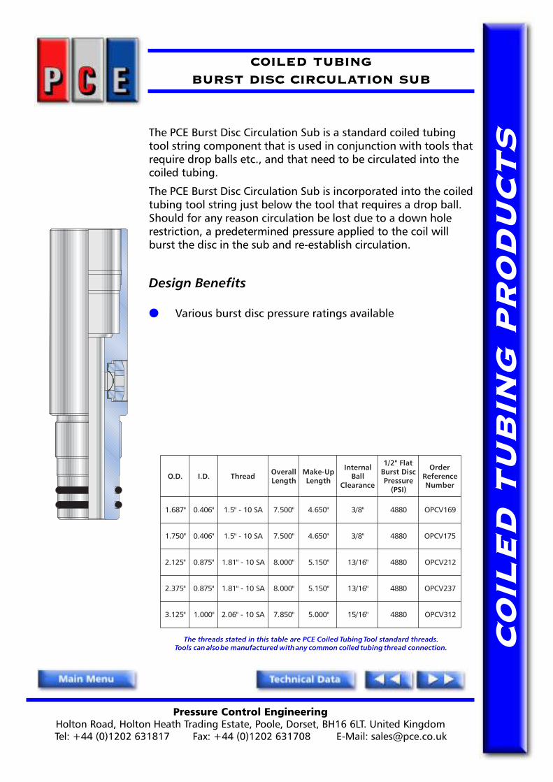
The PCE Burst Disc Circulation Sub is a standard coiled tubingtool string component that is used in conjunction with tools thatrequire drop balls etc., and that need to be circulated into thecoiled tubing.
The PCE Burst Disc Circulation Sub is incorporated into the coiledtubing tool string just below the tool that requires a drop ball.Should for any reason circulation be lost due to a down holerestriction, a predetermined pressure applied to the coil willburst the disc in the sub and re-establish circulation.
Design Benefits
● Various burst disc pressure ratings available
The threads stated in this table are PCE Coiled Tubing Tool standard threads.Tools can also be manufactured with any common coiled tubing thread connection.
.D.O .D.I daerhT llarevOhtgneL
pU-ekaMhtgneL
lanretnIllaB
ecnaraelC
talF"2/1csiDtsruB
erusserP)ISP(
redrOecnerefeRrebmuN
"786.1 "604.0 AS01-"5.1 "005.7 "056.4 "8/3 0884 961VCPO
"057.1 "604.0 AS01-"5.1 "005.7 "056.4 "8/3 0884 571VCPO
"521.2 "578.0 AS01-"18.1 "000.8 "051.5 "61/31 0884 212VCPO
"573.2 "578.0 AS01-"18.1 "000.8 "051.5 "61/31 0884 732VCPO
"521.3 "000.1 AS01-"60.2 "058.7 "000.5 "61/51 0884 213VCPO
Pressure Control EngineeringHolton Road, Holton Heath Trading Estate, Poole, Dorset, BH16 6LT. United KingdomTel: +44 (0)1202 631817 Fax: +44 (0)1202 631708 E-Mail: [email protected]
CO
ILE
D T
UB
ING
PR
OD
UC
TS
COILED TUBINGC.A.R.S.A.C CONNECTOR
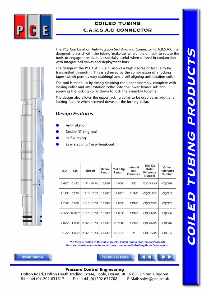
The PCE Combination Anti-Rotation Self Aligning Connector (C.A.R.S.A.C.) isdesigned to assist with the tubing 'make-up' where it is difficult to rotate thetools to engage threads. It is especially useful when utilized in conjunctionwith integral ball valves and deployment bars.
The design of the PCE C.A.R.S.A.C. allows a high degree of torque to betransmitted through it. This is achieved by the combination of a lockingtaper (which permits easy stabbing) and a self aligning anti-rotation collar.
The tool is made up by simply stabbing the upper assembly, complete withlocking collar and anti-rotation collar, into the lower female sub andscrewing the locking collar down to lock the assembly together.
The design also allows the upper jacking collar to be used as an additionallocking feature when screwed down on the locking collar.
Design Features
● Anti-rotation
● Double 'O' ring seal
● Self-aligning
● Easy stabbing / easy break-out
The threads stated in this table are PCE Coiled Tubing Tool standard threads.Tools can also be manufactured with any common coiled tubing thread connection.
.D.O .D.I daerhT llarevOhtgneL
pU-ekaMhtgneL
lanretnIllaB
ecnaraelC
tiKlaeSredrO
ecnerefeRrebmuN
redrOecnerefeRrebmuN
"786.1 "734.0 AS01-"5.1 "058.61 "000.41 "8/3 SK961CQC 961CQC
"521.2 "057.0 AS01-"18.1 "286.61 "238.31 "61/11 SK212CQC 212CQC
"052.2 "609.0 AS01-"18.1 "319.61 "360.41 "61/31 SK522CQC 522CQC
"573.2 ""609.0 AS01-"18.1 "319.61 "360.41 "61/31 SK732CQC 732CQC
"578.2 "000.1 AS01-"60.2 "716.32 "005.02 "61/51 SK782CQC 782CQC
"521.3 "260.1 AS01-"60.2 "716.32 "767.02 "1 SK213CQC 213CQC

Pressure Control EngineeringHolton Road, Holton Heath Trading Estate, Poole, Dorset, BH16 6LT. United KingdomTel: +44 (0)1202 631817 Fax: +44 (0)1202 631708 E-Mail: [email protected]
CO
ILE
D T
UB
ING
PR
OD
UC
TSThe PCE Coiled Tubing Grub Screw/ Dimple Connector allows the
attachment of Coiled Tubing to the CT Tool / Work String via theprovision of a threaded connection.
The connector is attached to the Coiled Tubing by grub screwsthat engage in preformed dimples in the tubing wall.
The dimples are formed by using the Dimple Tool that places theindents in identical positions to the screws on the connector.
The PCE Grub Screw/ Dimple Connectors have �o� ring pressureseals as standard and are also available with �v� packings as anoption to create the pressure seal.
Design Features
● High tensile strength● Internal pressure seal● Easy make up
COILED TUBINGDIMPLE / GRUB SCREW CONNECTOR
delioCgnibuT
retemaiD.D.O .D.I daerhT llarevO
htgneLpU-ekaM
htgneL
lanretnIllaB
ecnaraelC
redrOecnerefeRrebmuN
"4/1.1 "786.1 "057.0 AS01-"5.1 "521.8 "182.5 "61/11 961CC521D
"2/1.1 "521.2 "052.1 AS01-"18.1 "005.7 "786.4 "61/3.1 212CC051D
"4/3.1 "521.2 "052.1 AS01-"18.1 "057.7 "526.4 "61/3.1 212CC571D
"4/3.1 "573.2 "052.1 AS01-"18.1 "057.7 "739.4 "61/3.1 732CC571D
"2 "578.2 "005.1 AS01-"60.2 "578.7 "000.5 "61/7.1 782CC002D
"8/3.2 "521.3 "005.1 AS01-"60.2 "057.9 "005.6 "61/7.1 213CC732D
The threads stated in this table are PCE Coiled Tubing Tool standard threads.Tools can also be manufactured with any common coiled tubing thread connection.
Pressure Control EngineeringHolton Road, Holton Heath Trading Estate, Poole, Dorset, BH16 6LT. United KingdomTel: +44 (0)1202 631817 Fax: +44 (0)1202 631708 E-Mail: [email protected]
CO
ILE
D T
UB
ING
PR
OD
UC
TS
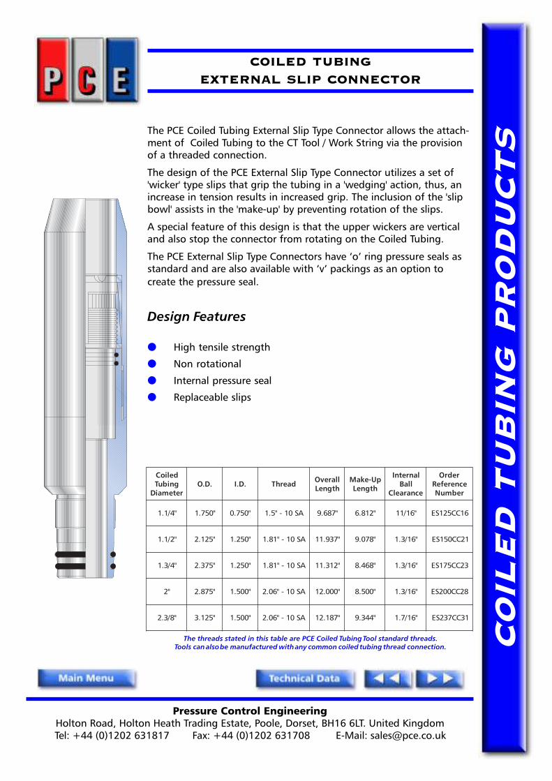
COILED TUBINGEXTERNAL SLIP CONNECTOR
The PCE Coiled Tubing External Slip Type Connector allows the attach-ment of Coiled Tubing to the CT Tool / Work String via the provisionof a threaded connection.
The design of the PCE External Slip Type Connector utilizes a set of'wicker' type slips that grip the tubing in a 'wedging' action, thus, anincrease in tension results in increased grip. The inclusion of the 'slipbowl' assists in the 'make-up' by preventing rotation of the slips.
A special feature of this design is that the upper wickers are verticaland also stop the connector from rotating on the Coiled Tubing.
The PCE External Slip Type Connectors have �o� ring pressure seals asstandard and are also available with �v� packings as an option tocreate the pressure seal.
Design Features
● High tensile strength
● Non rotational
● Internal pressure seal
● Replaceable slips
delioCgnibuT
retemaiD.D.O .D.I daerhT llarevO
htgneLpU-ekaM
htgneL
lanretnIllaB
ecnaraelC
redrOecnerefeRrebmuN
"4/1.1 "057.1 "057.0 AS01-"5.1 "786.9 "218.6 "61/11 61CC521SE
"2/1.1 "521.2 "052.1 AS01-"18.1 "739.11 "870.9 "61/3.1 12CC051SE
"4/3.1 "573.2 "052.1 AS01-"18.1 "213.11 "864.8 "61/3.1 32CC571SE
"2 "578.2 "005.1 AS01-"60.2 "000.21 "005.8 "61/3.1 82CC002SE
"8/3.2 "521.3 "005.1 AS01-"60.2 "781.21 "443.9 "61/7.1 13CC732SE
The threads stated in this table are PCE Coiled Tubing Tool standard threads.Tools can also be manufactured with any common coiled tubing thread connection.
Pressure Control EngineeringHolton Road, Holton Heath Trading Estate, Poole, Dorset, BH16 6LT. United KingdomTel: +44 (0)1202 631817 Fax: +44 (0)1202 631708 E-Mail: [email protected]
CO
ILE
D T
UB
ING
PR
OD
UC
TS
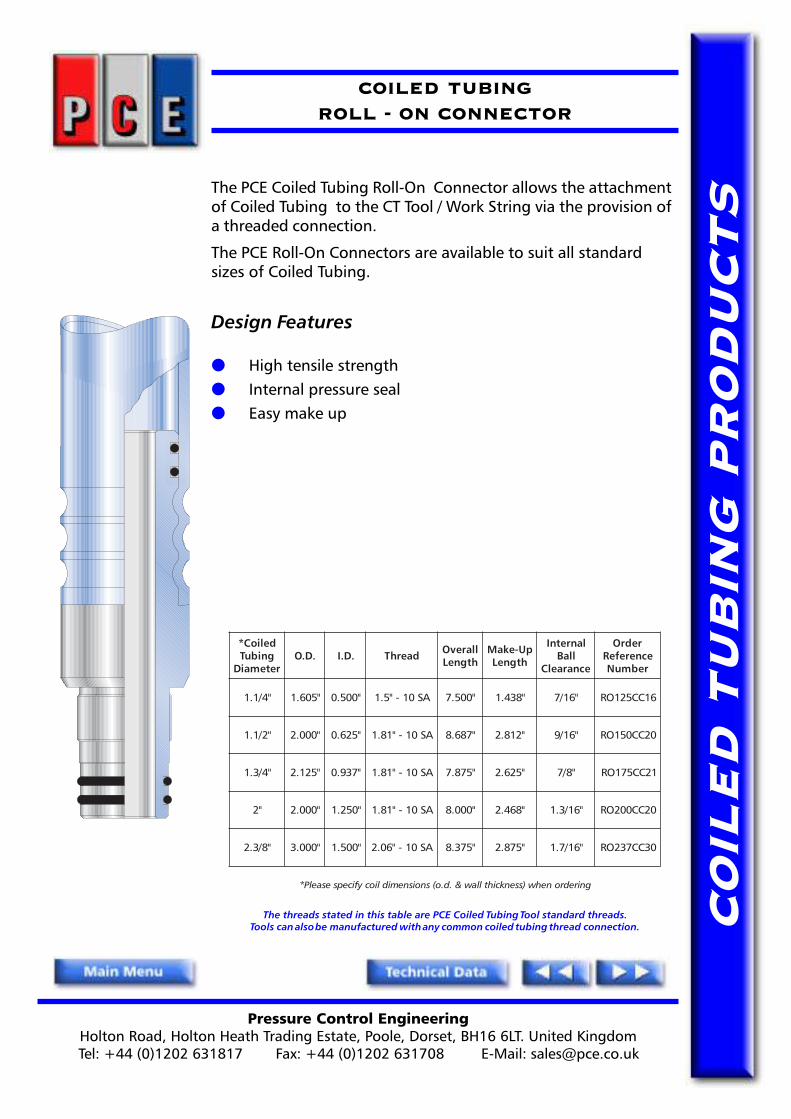
COILED TUBINGROLL - ON CONNECTOR
The PCE Coiled Tubing Roll-On Connector allows the attachmentof Coiled Tubing to the CT Tool / Work String via the provision ofa threaded connection.
The PCE Roll-On Connectors are available to suit all standardsizes of Coiled Tubing.
Design Features
● High tensile strength● Internal pressure seal● Easy make up
The threads stated in this table are PCE Coiled Tubing Tool standard threads.Tools can also be manufactured with any common coiled tubing thread connection.
delioC*gnibuT
retemaiD.D.O .D.I daerhT llarevO
htgneLpU-ekaM
htgneL
lanretnIllaB
ecnaraelC
redrOecnerefeRrebmuN
"4/1.1 "506.1 "005.0 AS01-"5.1 "005.7 "834.1 "61/7 61CC521OR
"2/1.1 "000.2 "526.0 AS01-"18.1 "786.8 "218.2 "61/9 02CC051OR
"4/3.1 "521.2 "739.0 AS01-"18.1 "578.7 "526.2 "8/7 12CC571OR
"2 "000.2 "052.1 AS01-"18.1 "000.8 "864.2 "61/3.1 02CC002OR
"8/3.2 "000.3 "005.1 AS01-"60.2 "573.8 "578.2 "61/7.1 03CC732OR
gniredronehw)ssenkcihtllaw&.d.o(snoisnemidliocyficepsesaelP*

Pressure Control EngineeringHolton Road, Holton Heath Trading Estate, Poole, Dorset, BH16 6LT. United KingdomTel: +44 (0)1202 631817 Fax: +44 (0)1202 631708 E-Mail: [email protected]
CO
ILE
D T
UB
ING
PR
OD
UC
TS
COILED TUBING CONNECTOR ANCILLARY TOOLSDIMPLE HAMMER & ROLL - ON CONNECTOR CRIMPING TOOL
DIMPLE HAMMER
The Dimple Hammer is used to accurately produce theindentations in the Coiled Tubing wall, required when using theGrub Screw/Dimple type Coiled Tubing connectors. (See Grubscrew/Dimple Connector)
The dimples are produced by screwing the round headed capscrews into the tubing wall by the same amount. The slidehammer aids installation and removal of the tool.
ROLL - ON CONNECTOR CRIMPING TOOL
Used in conjunction with the PCE Roll-On Connector, the Roll-OnConnector Crimping tool ensures easy field installation of thePCE Roll-On Connector to the coiled tubing.
The crimping tool has two interchangeable wheels, one of whichis used to swage the coiled tubing onto the Roll-On Connector.The other is a cutting wheel which can be used to cut the coiledtubing.
gnibuTdelioCretemaiD daerhT ecnerefeRredrO
rebmuN
"4/1.1 AS01-"5.1 521TCCD
"2/1.1 AS01-"18.1 051TCCD
"4/3.1 AS01-"18.1 571TCCD
"2 AS01-"60.2 002TCCD
"8/3.2 AS01-"60.2 732TCCD

Pressure Control EngineeringHolton Road, Holton Heath Trading Estate, Poole, Dorset, BH16 6LT. United KingdomTel: +44 (0)1202 631817 Fax: +44 (0)1202 631708 E-Mail: [email protected]
CO
ILE
D T
UB
ING
PR
OD
UC
TS
INTERNAL TUBING HONER
The Internal Tubing Honer is utilized to hone the bore of theCoiled Tubing when a smooth bore is required.
It is hand held and used in conjunction with an electric or airoperated drill. One honer will cover a range from 2" i.d. to 7" i.d.
INTERNAL TUBING REAMER
The Internal tubing reamer is a useful service tool that is used toremove the weld bead found on the internal bore of the CoiledTubing. This is achieved by locating the slot on the weld bead andthen rotating the tool using a suitable pipe wrench to break theweld.
The reamer has particular application in the preparation ofCoiled Tubing that uses 'Roll-on' type connectors. (See Roll-OnConnector)
COILED TUBING CONNECTOR ANCILLARY TOOLSINTERNAL TUBING REAMER & TUBING HONER

Pressure Control EngineeringHolton Road, Holton Heath Trading Estate, Poole, Dorset, BH16 6LT. United KingdomTel: +44 (0)1202 631817 Fax: +44 (0)1202 631708 E-Mail: [email protected]
CO
ILE
D T
UB
ING
PR
OD
UC
TS
COILED TUBINGDEPLOYMENT BAR SYSTEM
The PCE Coiled Tubing Deployment Bar System can be used to install long CoiledTubing toolstrings into wells where lubricator height is restricted.
By installing the lower part of the Coiled Tubing work string below the deploymentbar, the Coiled Tubing pipe rams can be closed around the waisted bar. Closing theintegral ball valves in the modified C.A.R.S.A.C. connector gives a double barrier tothe wellbore.
The modified PCE C.A.R.S.A.C. connector allows connection with the upper toolstring without the need to rotate the work string.
The PCE Coiled Tubing Deployment Bar System is available to suit most applicationsand configurations of Coiled Tubing pipe rams.
Design Features
● Double ball valve barrier
● Modified C.A.R.S.A.C. removes need to rotate Coiled Tubing
● Allows torque transmission
● Full bore flow through
The threads stated in this table are PCE Coiled Tubing Tool standard threads.Tools can also be manufactured with any common coiled tubing thread connection.
SRABTNEMYOLPED
.D.OdecudeRgnipmalCretemaiD
decudeR*gnipmalCretemaiD
htgneL
.D.I daerhT llarevOhtgneL
pU-ekaMhtgneL
lanretnIllaB
ecnaraelC
redrOecnerefeRrebmuN
"786.1 "052.1 "63 "005.0 AS01-"5.1 "058.05 "000.84 "61/7 961PD521B
"057.1 "052.1 "63 "005.0 AS01-"5.1 "058.05 "000.84 "61/7 571PD521B
"521.2 "005.1 "63 "057.0 AS01-"18.1 "058.05 "000.84 "61/11 212PD051B
"573.2 "057.1 "63 "057.0 AS01-"18.1 "058.05 "000.84 "61/11 732PD571B
"521.3 "000.2 "63 "000.1 AS01-"60.2 "058.05 "000.84 "61/51 213PD002B
gniredronehwyficepsesaelP.tnemeriuqerhtgnelsremotsucotdeilppuseboslanac)"63htgneldradnats(retemaidgnipmalcraBtnemyolpeD*
SMETSYSRABTNEMYOLPED
delioCgnibuT
retemaiD.D.O .D.I daerhT llarevO
htgneLpU-ekaM
htgneL stnetnoCmetsyS
"4/1.1 "786.1 "734.0 AS01-"5.1 "070.87 "22.57 rotcennoCC.A.S.R.A.C
ylleKllaBlauDevlaVkcoC
raBtnemyolpeDsnoitpo-dradnatS"84(
)elbaliava
"2/1.1 "521.2 "057.0 AS01-"18.1 "209.77 "50.57
"4/3.1 "573.2 "057.0 AS01-"18.1 "331.87 "82.57
"2 "521.3 "000.1 AS01-"60.2 "716.17 "77.86

Pressure Control EngineeringHolton Road, Holton Heath Trading Estate, Poole, Dorset, BH16 6LT. United KingdomTel: +44 (0)1202 631817 Fax: +44 (0)1202 631708 E-Mail: [email protected]
CO
ILE
D T
UB
ING
PR
OD
UC
TS
COILED TUBINGFISHING GRAB
The PCE Coiled Tubing Fishing Grab is used to retrieve lost orbroken wireline from the wellbore.
The PCE Coiled Tubing Fishing Grabs are available in a range ofsizes to suit standard tubing diameter.
Design Benefits
● Flow through facility● Simple design● Robust construction● External fish neck available
The threads stated in this table are PCE Coiled Tubing Tool standard threads.Tools can also be manufactured with any common coiled tubing thread connection.
.D.O .D.I daerhT llarevOhtgneL
pU-ekaMhtgneL
thgieW)sbl(
sbraBx7lanretnInoisurtorP
lanretxEgnihsiF
kceN
redrOecnerefeRrebmuN
"052.2 "526.0 AS01-"5.1 "000.42 "000.42 48.9 "009.0 "57.1 522GF
"057.2 "057.0 AS01-"18.1 "000.52 "000.52 05.21 "052.1 "31.2 572GF
"005.3 "057.0 AS01-"18.1 "000.52 "000.52 05.61 "26.1 "31.2 053GF
"000.4 "000.1 AS01-"60.2 "005.62 "005.62 57.91 "26.1 "31.2 004GF

Pressure Control EngineeringHolton Road, Holton Heath Trading Estate, Poole, Dorset, BH16 6LT. United KingdomTel: +44 (0)1202 631817 Fax: +44 (0)1202 631708 E-Mail: [email protected]
CO
ILE
D T
UB
ING
PR
OD
UC
TSThe PCE Coiled Tubing Flow Activated Alligator Grab is a fishing
tool used to catch and retrieve loose objects from within the wellbore. The PCE Coiled Tubing Flow Activated Alligator Grab is runin the permanently closed position and is flow activated to theopen grab position by circulating fluid and creating a pressuredifferential at the tool.
Please note The PCE Coiled Tubing Flow Activated Alligator Grabis not designed to withstand heavy jarring operations in theevent that the jaws have gripped onto any firmly stuck �fish�.
The PCE Coiled Tubing Flow Activated Alligator Grab shouldalways be run in conjunction with a PCE Sequencing Tool.
Design Benefits
● Variable grab lengths available● Optional external fishneck
PCE COILED TUBINGFLOW ACTIVATED ALLIGATOR GRAB
The threads stated in this table are PCE Coiled Tubing Tool standard threads.Tools can also be manufactured with any common coiled tubing thread connection.
.D.O .D.I daerhT llarevOhtgneL
pU-ekaMhtgneL
thgieW)sbl(
lanretnIhsiFkceNeziS
sbarGredrO
ecnerefeRrebmuN
"008.2 "093.0 AS01-"18.1 "000.82 "000.82 81.66 "313.2 barG"4/barG"3lanoitpO 082AFGA

Pressure Control EngineeringHolton Road, Holton Heath Trading Estate, Poole, Dorset, BH16 6LT. United KingdomTel: +44 (0)1202 631817 Fax: +44 (0)1202 631708 E-Mail: [email protected]
CO
ILE
D T
UB
ING
PR
OD
UC
TS
COILED TUBING FLOW ACTIVATEDRELEASABLE FISHING/BULLDOG SPEAR
The PCE Flow Activated Coiled Tubing Releasable Fishing/BulldogSpear is a variable catch internal spear used to retrieve a lostcylindrical fish from the well bore.
A complete range of slips is available for each size tool. Tooperate, simply run into the fish and set down weight, pick upand retrieve the fish. To release from the fish simply set downweight, circulate in conjunction with a PCE Hydraulic SequencingTool above the spear. The spear will then release due to the flowcreated differential.
The PCE Flow Activated Releasable Fishing/Bulldog Spears areavailable in a range of sizes.
Design Benefits
● Flow or drop ball activated● Hardened & double tempered slips● Robust construction● Variable slips sizes for each tool
.D.O .D.I daerhT llarevOhtgneL
pU-ekaMhtgneL
lanimoNeziS
dradnatSspilS
tiKlaeSredrO
ecnerefeRrebmuN
redrOecnerefeRrebmuN
"058.1 "052.0 AS01-"5.1 "083.81 "083.81 "2"521.1
ot"052.1
SK581AFRS 581AFRS
"052.2 "093.0 01-"18.1AS "026.12 "026.12 "5.2
"057.1ot
"578.1SK522AFRS 522AFRS
STESPILSRAEPSGODLLUB/GNIHSIFGNIBUTDELIOC
llarevOhtgneL daerhT lanimoN
eziS ytitnauQ seziS
"000.4 21-"8/1.12-NU "2 5 "526.1-"5.1,"5.1-"573.1,"573.1-"52.1
"578.1-"57.1,"57.1-"526.1
"000.6 21-"8/5.12-NU "5.2 5 "521.2-"2,"2-"578.1,"578.1-"57.1
"573.2-"52.2,"52.2-"521.2
The Threads stated in this table are PCE Coiled Tubing Tool standard threads.Tools can also be manufactured with any common coiled tubing thread connection.

Pressure Control EngineeringHolton Road, Holton Heath Trading Estate, Poole, Dorset, BH16 6LT. United KingdomTel: +44 (0)1202 631817 Fax: +44 (0)1202 631708 E-Mail: [email protected]
CO
ILE
D T
UB
ING
PR
OD
UC
TS
COILED TUBINGNON RELEASABLE OVERSHOT
The PCE Non Releasable Overshot is a fishing tool utilised tocatch coiled tubing or downhole tools without a fish neck.
The latching mechanism of the tool utilises hardened andtempered parallel slips to grip the outside diameter of the 'fish'.
Where required, threaded main bodies are available to enablebell guides to be fitted for fishing small diameter tools in largeinternal diameter tubing. They can also be supplied with internalor external fishing necks looking up to enable them to be used inconjunction with a PCE Heavy Duty Running / Pulling Tool.
Design Benefits
● Hardened & double tempered slips● Optional use of bell guides for large i.d. tubing.● High strength latching● Optional internal or external fish neck
The threads stated in this table are PCE Coiled Tubing Tool standard threads.Tools can also be manufactured with any common coiled tubing thread connection.
.D.O .D.I daerhTelisneThtgnertS
)ecivreSdtS(
elisneThtgnertS
H( 2 )ecivreSS
llarevOhtgneL
pU-ekaMhtgneL thgieW lanimoN
eziS
redrOecnerefeRrebmuN
"057.1 "057.0 AS01-"5.1 sbl000,14 sbl000,03 "059.9 "059.9 08.2 "2 571RNO
"000.2 "057.0 AS01-"5.1 sbl000,86 sbl000,05 "059.9 "059.9 88.4 "5.2 002RNO
"052.2 "057.0 AS01-"18.1 sbl000,86 sbl000,05 "781.01 "781.01 04.7 "5.2 522RNO
"005.2 "057.0 AS01-"18.1 sbl000,29 sbl000,76 "522.01 "522.01 21.01 "3 052RNO
"057.2 "057.0 AS01-"18.1 sbl000,69 sbl000,86 "213.01 "213.01 22.31 "3 572RNO
"000.3 "057.0 AS01-"18.1 sbl000,28 sbl000,06 "734.01 "734.01 17.61 "5.3 003RNO
"052.3 "057.0 AS01-"60.2 sbl000,761 sbl570,121 "734.01 "734.01 43.02 "5.3 523RNO
"006.3 "057.0 AS01-"60.2 sbl000,191 sbl000,831 "005.01 "005.01 60.62 "4 063RNO
Pressure Control EngineeringHolton Road, Holton Heath Trading Estate, Poole, Dorset, BH16 6LT. United KingdomTel: +44 (0)1202 631817 Fax: +44 (0)1202 631708 E-Mail: [email protected]
CO
ILE
D T
UB
ING
PR
OD
UC
TS
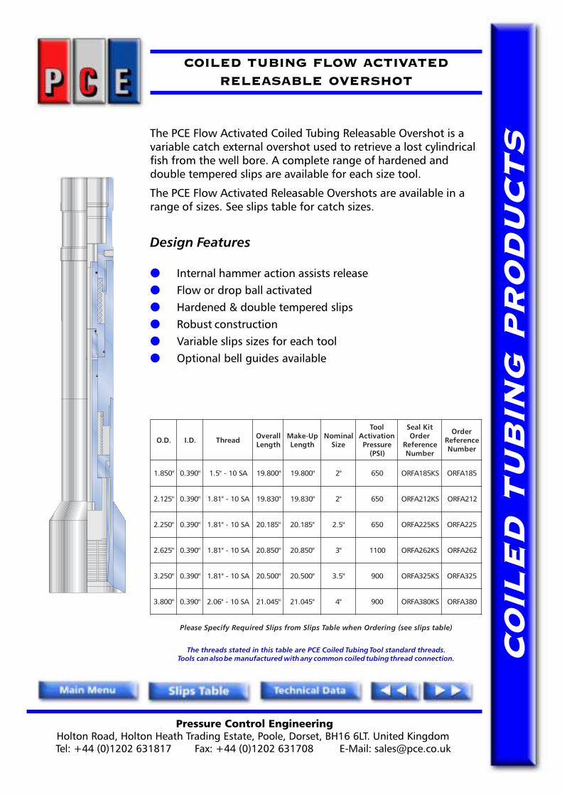
COILED TUBING FLOW ACTIVATEDRELEASABLE OVERSHOT
The PCE Flow Activated Coiled Tubing Releasable Overshot is avariable catch external overshot used to retrieve a lost cylindricalfish from the well bore. A complete range of hardened anddouble tempered slips are available for each size tool.
The PCE Flow Activated Releasable Overshots are available in arange of sizes. See slips table for catch sizes.
Design Features
● Internal hammer action assists release● Flow or drop ball activated● Hardened & double tempered slips● Robust construction● Variable slips sizes for each tool● Optional bell guides available
The threads stated in this table are PCE Coiled Tubing Tool standard threads.Tools can also be manufactured with any common coiled tubing thread connection.
.D.O .D.I daerhT llarevOhtgneL
pU-ekaMhtgneL
lanimoNeziS
looTnoitavitcA
erusserP)ISP(
tiKlaeSredrO
ecnerefeRrebmuN
redrOecnerefeRrebmuN
"058.1 "093.0 AS01-"5.1 "008.91 "008.91 "2 056 SK581AFRO 581AFRO
"521.2 "093.0 AS01-"18.1 "038.91 "038.91 "2 056 SK212AFRO 212AFRO
"052.2 "093.0 AS01-"18.1 "581.02 "581.02 "5.2 056 SK522AFRO 522AFRO
"526.2 "093.0 AS01-"18.1 "058.02 "058.02 "3 0011 SK262AFRO 262AFRO
"052.3 "093.0 AS01-"18.1 "005.02 "005.02 "5.3 009 SK523AFRO 523AFRO
"008.3 "093.0 AS01-"60.2 "540.12 "540.12 "4 009 SK083AFRO 083AFRO
)elbatspilsees(gniredrOnehwelbaTspilSmorfspilSderiuqeRyficepSesaelP

Pressure Control EngineeringHolton Road, Holton Heath Trading Estate, Poole, Dorset, BH16 6LT. United KingdomTel: +44 (0)1202 631817 Fax: +44 (0)1202 631708 E-Mail: [email protected]
CO
ILE
D T
UB
ING
PR
OD
UC
TS
COILED TUBING RELEASABLE OVERSHOT& NON RELEASABLE OVERSHOT SLIPS TABLE
lanimoNeziS "2 "2/1-2 "3 "2/1-3 "4
lautcA.D.O "058.1 "052.2 "526.2 "052.3 "008.3
lanimoNeziSpilS
egnaRhctaCrebmuNtraP
egnaRhctaCrebmuNtraP
egnaRhctaCrebmuNtraP
egnaRhctaCrebmuNtraP
egnaRhctaCrebmuNtraP
"2/1-1 "61/9ot"61/7 "61/9ot"61/7 "61/9ot"8/3 "8/5ot"8/3
"8/5 "61/11ot"61/9 "61/11ot"61/9 "4/3ot"61/9
"4/3 "61/31ot"61/11 "61/31ot"61/11 "8/7ot"8/5
"8/7 "61/51ot"61/31 "61/51ot"61/31 "61/51ot"4/3
"1 "61/1-1ot"61/51 "61/1-1ot"61/51 "8/1-1ot"61/51 "61/1-1ot"8/7 "8/1-1ot"8/7
"8/1-1 "61/3-1ot"61/1-1 "61/3-1ot"61/1-1 "4/1-1ot"61/1-1
"4/1-1 "61/5-1ot"61/3-1 "61/5-1ot"61/3-1 "61/5-1ot"8/1-1 "8/3-1ot"8/1-1
"8/3-1 "61/7-1ot"61/5-1 "61/7-1ot"61/5-1 "2/1-1ot"61/5-1 "61/7-1ot"4/1-1
"2/1-1 "61/9-1ot"61/7-1 "61/9-1ot"61/7-1 "8/5-1ot"61/7-1 "8/5-1ot"8/3-1
"8/5-1 "61/11-1ot"61/9-1 "61/11-1ot"2/1-1
"4/3-1 "61/11-1ot"61/11-1 "8/7-1ot"61/11-1 "61/31-1ot"8/5-1 "8/7-1ot"8/5-1
"8/7-1 "2ot"61/31-1
"2 "61/1-2ot"8/7-1 "61/3-2ot"2 "8/1-2ot"8/7-1
"4/1-2 "61/5-2ot"8/1-2 "8/3-2ot"8/1-2
"2/1-2 "8/5-2ot"8/3-2
"4/3-2 "8/7-2ot"8/5-2
STESPILSELPPARG
eziSlanimoN "2 "5.2 "3 "5.3 "4
gnibuTdelioCeziS "4/1.1 "2/1.1 "4/3.1 "2 "8/3.2
htgneLllarevO "052.5 "052.5 "028.4 "000.6 "000.6
daerhT 2-NU21-"8/3.1 2-NU21-"8/5.1 2-NU21-"2 2-NU61-"61/7.2 2-NU21-"3
egnaR "2/1.1-"2/1 "4/3.1-"2/1 "2-"2/1 "2-"8/7 "4/3.2-"2/1
ytitnauQ 9 11 9 8 01
Pressure Control EngineeringHolton Road, Holton Heath Trading Estate, Poole, Dorset, BH16 6LT. United KingdomTel: +44 (0)1202 631817 Fax: +44 (0)1202 631708 E-Mail: [email protected]
CO
ILE
D T
UB
ING
PR
OD
UC
TS
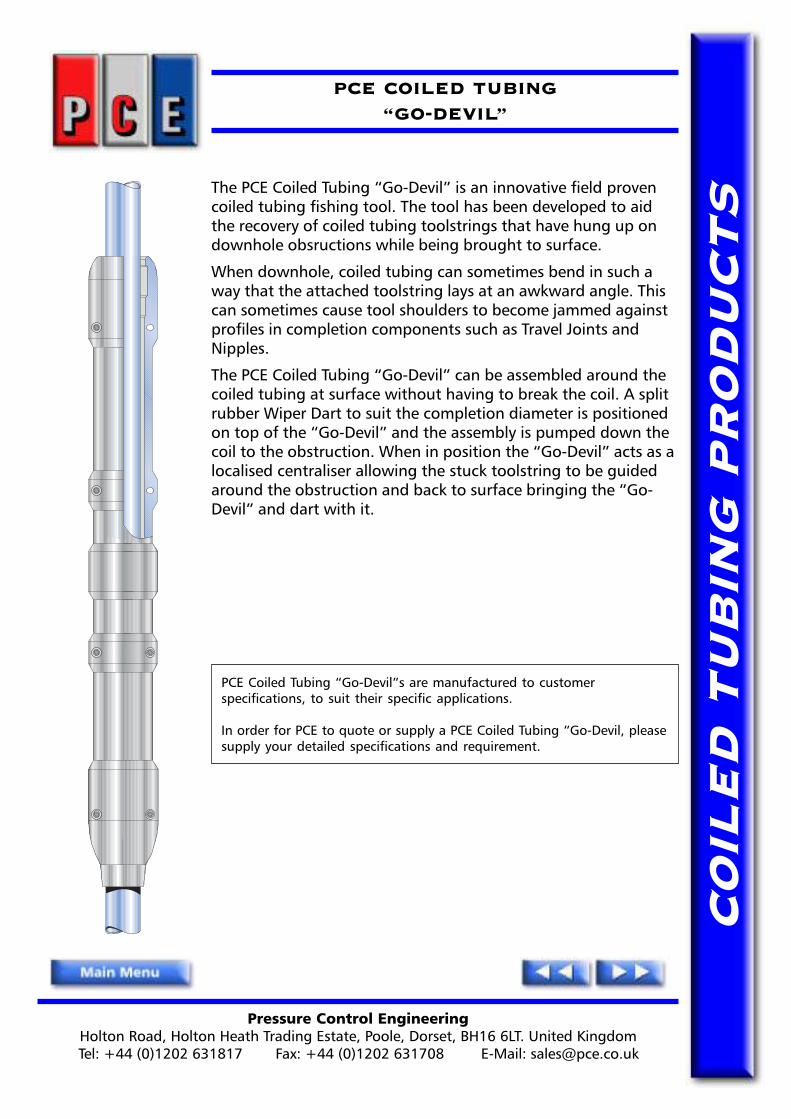
PCE COILED TUBING�GO-DEVIL�
The PCE Coiled Tubing �Go-Devil� is an innovative field provencoiled tubing fishing tool. The tool has been developed to aidthe recovery of coiled tubing toolstrings that have hung up ondownhole obsructions while being brought to surface.
When downhole, coiled tubing can sometimes bend in such away that the attached toolstring lays at an awkward angle. Thiscan sometimes cause tool shoulders to become jammed againstprofiles in completion components such as Travel Joints andNipples.
The PCE Coiled Tubing �Go-Devil� can be assembled around thecoiled tubing at surface without having to break the coil. A splitrubber Wiper Dart to suit the completion diameter is positionedon top of the �Go-Devil� and the assembly is pumped down thecoil to the obstruction. When in position the �Go-Devil� acts as alocalised centraliser allowing the stuck toolstring to be guidedaround the obstruction and back to surface bringing the �Go-Devil� and dart with it.
PCE Coiled Tubing �Go-Devil�s are manufactured to customerspecifications, to suit their specific applications.
In order for PCE to quote or supply a PCE Coiled Tubing �Go-Devil, pleasesupply your detailed specifications and requirement.

Pressure Control EngineeringHolton Road, Holton Heath Trading Estate, Poole, Dorset, BH16 6LT. United KingdomTel: +44 (0)1202 631817 Fax: +44 (0)1202 631708 E-Mail: [email protected]
CO
ILE
D T
UB
ING
PR
OD
UC
TS
COILED TUBINGFLOW ACTIVATED INDEXING TOOL
The PCE Flow Activated Indexing Tool is designed for use whencontrolled rotation of the lower tool string is required. The toolhas particular application for rotating fishing overshots onto thefish.
The PCE Flow Activated Indexing Tool is designed on a rotatingcam principle. The tool does not stroke downward in order toindex the cam, since this action is achieved internally.
Design Benefits
● Flow activated - no drop balls required● 6, 8 or 12 stage 360 degree rotation● Low pressure to pulse
The threads stated in this table are PCE Coiled Tubing Tool standard threads.Tools can also be manufactured with any common coiled tubing thread connection.
LOOTGNIXEDNIDETAVITCAWOLF
.D.O .D.I daerhT
elisneThtgnertS
dtS()ecivreS
elisneThtgnertS
H( 2S)ecivreS
llarevOhtgneL
pU-ekaMhtgneL
thgieW)sbl(
lanretnIllaB
ecnaraelC
eergeDspetS
redrOecnerefeRrebmuN
gnitarepOserusserP
"521.2 "057.0 AS01-"18.1 sbl000,83 sbl005,72 "051.12 "003.81 43.41 "61/11 °06x6 T212XDNI
etarepOotISP008
rewoPnoeuqroTxaMsbl/tf03=ekortS
"578.2 "000.1 AS01-"18.1 sbl000,111 sbl005,08 "094.82 "046.52 45.83 "61/51 °54x8 T782XDNI
etarepOotISP0001
rewoPnoeuqroTxaMsbl/tf13=ekortS
)euqroThgiH(LOOTGNIXEDNIDETAVITCAWOLF
"521.2 "784.0 AS01-"18.1 sbl000,64 sbl005,33 "058.73 "000.53 82.33 "61/7 °03x21 TH212XDNIISP0002/ISP0001
etarepOotlaitnereffiD
detavitcAerusserPlooTerusserP/erusserP
euqroTsbl/tf001"052.2 "784.0 AS01-"18.1 sbl000,64 sbl005,33 "058.82 "000.62 98.72 "61/7 °03x21 TH522XDNI

Pressure Control EngineeringHolton Road, Holton Heath Trading Estate, Poole, Dorset, BH16 6LT. United KingdomTel: +44 (0)1202 631817 Fax: +44 (0)1202 631708 E-Mail: [email protected]
CO
ILE
D T
UB
ING
PR
OD
UC
TS
COILED TUBINGJETTING INDEXING TOOL
The PCE Flow Activated Hydraulic Jetting Indexing Tool is used torotate jetting nozzles in a controlled 36° or 60° incrementalmanner by applying intermittent surface pump pressure.Downward movement of the lower half of the tool occurs duringthe indexing operation.
Design Features
● Flow activated (No drop balls required)● Full bore opening● Easy to operate● Simple construction● 6 x 60° or 10 x 36° rotation options available
The threads stated in this table are PCE Coiled Tubing Tool standard threads.Tools can also be manufactured with any common coiled tubing thread connection.
.D.O .D.I daerhT llarevOhtgneL
pU-ekaMhtgneL
thgieW)sbl(
lanretnIllaB
ecnaraelC
redrOecnerefeRrebmuN
"786.1 "052.0 AS01-"5.1 "058.13 "000.92 11.71 "61/3 961TIJ
"057.1 "052.0 AS01-"5.1 "058.13 "000.92 56.81 "61/3 571TIJ
"521.2 "005.0 AS01-"18.1 "616.62 "667.32 97.12 "61/7 212TIJ
"573.2 "005.0 AS01-"18.1 "053.62 "005.32 61.32 "61/7 732TIJ
"521.3 "057.0 AS01-"60.2 "056.22 "008.91 78.43 "61/11 213TIJ

Pressure Control EngineeringHolton Road, Holton Heath Trading Estate, Poole, Dorset, BH16 6LT. United KingdomTel: +44 (0)1202 631817 Fax: +44 (0)1202 631708 E-Mail: [email protected]
CO
ILE
D T
UB
ING
PR
OD
UC
TS
COILED TUBINGDOWNSTROKE HYDRAULIC JAR
The PCE CT Downstroke Hydraulic Jar is used as a componentpart of the Coiled Tubing work/tool string when a downward jaraction is required.
The design of the PCE Downstroke Hydraulic Jar incorporates asingle piece mandrel contained within a closed and balancedhydraulic system, which prevents contamination from well borefluids and ensures operational efficiency.
The PCE CT Downstroke Hydraulic Jars are available in a range ofsizes.
Design Benefits
● Full flow through bore
● Specifically designed for CT use
● Single piece mandrel
● Closed & balanced hydraulic system
The threads stated in this table are PCE Coiled Tubing Tool standard threads.Tools can also be manufactured with any common coiled tubing thread connection.
.D.O .D.I daerhT
elisneThtgnertS
dtS()ecivreS
elisneThtgnertS
H( 2S)ecivreS
llarevOhtgneL
pU-ekaMhtgneL
thgieW)sbl(
lanretnIllaB
ecnaraelC
ekortShtgneL
raJekortS
redrOecnerefeRrebmuN
"057.1 "573.0 AS01-"5.1 sbl000,06 sbl000,44 "058.83 "000.63 83.32 "61/5 "578.8 "4 571DHRJ
"521.2 "573.0 AS01-"18.1 sbl000,86 sbl000,05 "058.44 "000.24 50.23 "61/5 "9 "4 212DHRJ

Pressure Control EngineeringHolton Road, Holton Heath Trading Estate, Poole, Dorset, BH16 6LT. United KingdomTel: +44 (0)1202 631817 Fax: +44 (0)1202 631708 E-Mail: [email protected]
CO
ILE
D T
UB
ING
PR
OD
UC
TS
COILED TUBINGUPSTROKE HYDRAULIC JAR
The PCE Coiled Tubing Upstroke Hydraulic Jar is incorporatedas a part of the Coiled Tubing work/tool string when anupward jar action is required.
The design of the PCE Upstroke Hydraulic Jar incorporates asingle piece mandrel, contained within a closed and balancedhydraulic system, which prevents contamination from wellbore fluids and ensures operational efficiency.
Design Benefits
● Full flow through bore
● Specifically designed for CT use
● Single piece mandrel
● Closed & balanced hydraulic system
The threads stated in this table are PCE Coiled Tubing Tool standard threads.Tools can also be manufactured with any common coiled tubing thread connection.
.D.O .D.I daerhT
elisneThtgnertS
dtS()ecivreS
elisneThtgnertS
H( 2S)ecivreS
llarevOhtgneL
pU-ekaMhtgneL
thgieW)sbl(
lanretnIllaB
ecnaraelC
ekortShtgneL
tiKlaeSredrO
ecnerefeRrebmuN
redrOecnerefeRrebmuN
"057.1 "573.0 AS01-"5.1 sbl000,82 sbl000,02 "058.54 "000.34 39.42 "61/5 "31.4 SK571UHRJ 571UHRJ
"521.2 "005.0 AS01-"18.1 sbl000,06 sbl000,44 "001.34 "052.04 52.13 "61/7 "4 SK212UHRJ 212UHRJ
"052.2 "005.0 AS01-"18.1 sbl000,06 sbl000,44 "001.34 "052.04 21.83 "61/7 "4 SK522UHRJ 522UHRJ
"521.3 "000.1 AS01-"60.2 sbl000,831 sbl000,101 "001.36 "052.06 45.05 "61/51 "1.4 SK213UHRJ 213UHRJ
Pressure Control EngineeringHolton Road, Holton Heath Trading Estate, Poole, Dorset, BH16 6LT. United KingdomTel: +44 (0)1202 631817 Fax: +44 (0)1202 631708 E-Mail: [email protected]
CO
ILE
D T
UB
ING
PR
OD
UC
TS
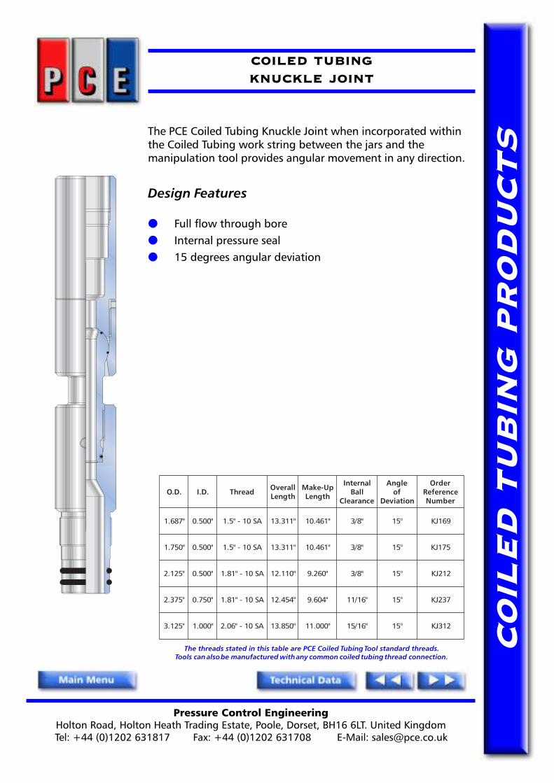
COILED TUBINGKNUCKLE JOINT
The PCE Coiled Tubing Knuckle Joint when incorporated withinthe Coiled Tubing work string between the jars and themanipulation tool provides angular movement in any direction.
Design Features
● Full flow through bore● Internal pressure seal● 15 degrees angular deviation
The threads stated in this table are PCE Coiled Tubing Tool standard threads.Tools can also be manufactured with any common coiled tubing thread connection.
.D.O .D.I daerhT llarevOhtgneL
pU-ekaMhtgneL
lanretnIllaB
ecnaraelC
elgnAfo
noitaiveD
redrOecnerefeRrebmuN
"786.1 "005.0 AS01-"5.1 "113.31 "164.01 "8/3 °51 961JK
"057.1 "005.0 AS01-"5.1 "113.31 "164.01 "8/3 °51 571JK
"521.2 "005.0 AS01-"18.1 "011.21 "062.9 "8/3 °51 212JK
"573.2 "057.0 AS01-"18.1 "454.21 "406.9 "61/11 °51 732JK
"521.3 "000.1 AS01-"60.2 "058.31 "000.11 "61/51 °51 213JK

Pressure Control EngineeringHolton Road, Holton Heath Trading Estate, Poole, Dorset, BH16 6LT. United KingdomTel: +44 (0)1202 631817 Fax: +44 (0)1202 631708 E-Mail: [email protected]
CO
ILE
D T
UB
ING
PR
OD
UC
TS
COILED TUBINGTORQUE THRU KNUCKLE JOINT
The PCE Coiled Tubing Torque-Thru Knuckle Joint whenincorporated within the Coiled Tubing work string between thejars and the manipulation tool provides angular movement inany direction.
The ball and socket of the knuckle have a key that preventsrotation but still allows full angular movement.
Design Features
● Full flow through bore● Internal pressure seal● 15 degrees angular deviation● Torque Thru capability
The threads stated in this table are PCE Coiled Tubing Tool standard threads.Tools can also be manufactured with any common coiled tubing thread connection.
.D.O .D.I daerhT llarevOhtgneL
pU-ekaMhtgneL
lanretnIllaB
ecnaraelC
elgnAfo
noitaiveD
redrOecnerefeRrebmuN
"786.1 "005.0 AS01-"5.1 "113.31 "164.01 "8/3 °51 961TTJK
"057.1 "005.0 AS01-"5.1 "113.31 "164.01 "8/3 °51 571TTJK
"521.2 "057.0 AS01-"18.1 "915.31 "966.01 "61/11 °51 212TTJK
"052.2 "057.0 AS01-"18.1 "915.31 "966.01 "61/11 °51 522TTJK
"573.2 "057.0 AS01-"18.1 "569.31 "511.11 "61/11 °51 732TTJK
"521.3 "000.1 AS01-"60.2 "059.41 "001.21 "61/51 °51 213TTJK
Pressure Control EngineeringHolton Road, Holton Heath Trading Estate, Poole, Dorset, BH16 6LT. United KingdomTel: +44 (0)1202 631817 Fax: +44 (0)1202 631708 E-Mail: [email protected]
CO
ILE
D T
UB
ING
PR
OD
UC
TS
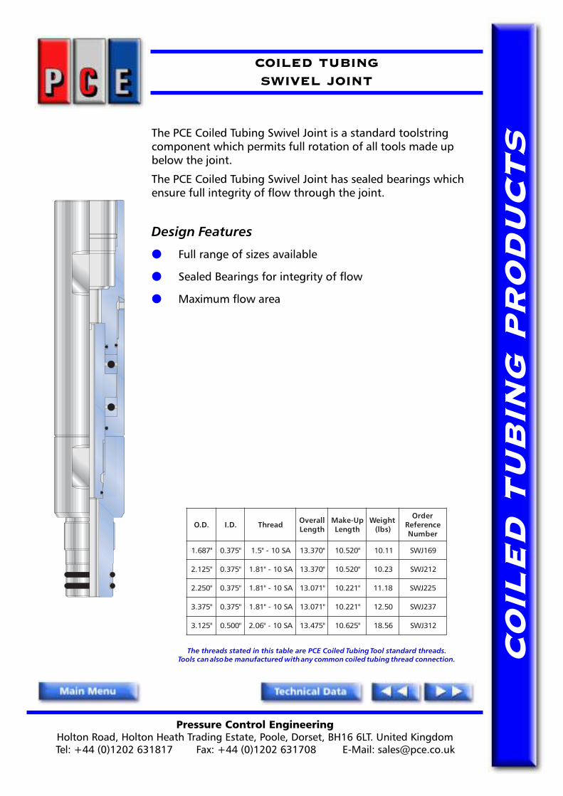
COILED TUBINGSWIVEL JOINT
The PCE Coiled Tubing Swivel Joint is a standard toolstringcomponent which permits full rotation of all tools made upbelow the joint.
The PCE Coiled Tubing Swivel Joint has sealed bearings whichensure full integrity of flow through the joint.
Design Features
● Full range of sizes available
● Sealed Bearings for integrity of flow
● Maximum flow area
The threads stated in this table are PCE Coiled Tubing Tool standard threads.Tools can also be manufactured with any common coiled tubing thread connection.
.D.O .D.I daerhT llarevOhtgneL
pU-ekaMhtgneL
thgieW)sbl(
redrOecnerefeRrebmuN
"786.1 "573.0 AS01-"5.1 "073.31 "025.01 11.01 961JWS
"521.2 "573.0 AS01-"18.1 "073.31 "025.01 32.01 212JWS
"052.2 "573.0 AS01-"18.1 "170.31 "122.01 81.11 522JWS
"573.3 "573.0 AS01-"18.1 "170.31 "122.01 05.21 732JWS
"521.3 "005.0 AS01-"60.2 "574.31 "526.01 65.81 213JWS

Pressure Control EngineeringHolton Road, Holton Heath Trading Estate, Poole, Dorset, BH16 6LT. United KingdomTel: +44 (0)1202 631817 Fax: +44 (0)1202 631708 E-Mail: [email protected]
CO
ILE
D T
UB
ING
PR
OD
UC
TS
COILED TUBINGLEAD IMPRESSION BLOCK
The PCE Lead Impression Block is an adapted standard wirelineservice tool used to obtain impressions of foreign objects in thetubing string to assist in identification of the object and thusselection of the correct fishing tool.
The PCE Lead Impression Blocks are available in a range of sizes.
Design Benefits
● 'Wash out' prevention sleeve● Easily refillable● Optional external fish neck
The threads stated in this table are PCE Coiled Tubing Tool standard threads.Tools can also be manufactured with any common coiled tubing thread connection.
.D.O .D.I daerhT llarevOhtgneL
pU-ekaMhtgneL
thgieW)sbl(
redrOecnerefeRrebmuN
"057.1 "573.0 AS01-"5.1 "000.21 "000.21 51.7 571BIL
"000.2 "573.0 AS01-"5.1 "000.21 "000.21 43.9 002BIL
"521.2 "734.0 AS01-"18.1 "000.21 "000.21 45.01 212BIL
"005.2 "005.0 AS01-"18.1 "000.21 "000.21 02.31 052BIL
"057.2 "005.0 AS01-"18.1 "000.21 "000.21 85.41 572BIL
"000.3 "000.1 AS01-"18.1 "000.21 "000.21 21.71 003BIL
"052.3 "001.1 AS01-"18.1 "000.21 "000.21 94.12 523BIL
"005.3 "001.1 AS01-"18.1 "027.21 "027.21 38.42 053BIL

Pressure Control EngineeringHolton Road, Holton Heath Trading Estate, Poole, Dorset, BH16 6LT. United KingdomTel: +44 (0)1202 631817 Fax: +44 (0)1202 631708 E-Mail: [email protected]
CO
ILE
D T
UB
ING
PR
OD
UC
TS
COILED TUBINGDIMPLE/GRUB SCREW CONNECTOR TOOLHEAD
The PCE M.P. TOOL HEAD has been introduced in recognition of the ever increasing demand by operators to saverig up time, shorten the primary tools string length and most importantly increase operator safety. By combiningthe three basic tools required for all coiled tubing runs into one assembly i.e. the coil connector, twin flappercheck valve and an emergency release joint, these objectives are met.
The M.P. TOOL HEAD is available as a standard combination tool coupled with a range of options that will suitall client�s requirements.
The benefits of the new tool are:
1) Saving rig up time - One connection to make up and test.2) Convenient handling - The make up length is between 26� -31� saving 13� on conventional tools.3) Safety & reliability - Less connections to make up and break out - reduces the accident risk, and with
less �O� rings to leak reduces the risk of tool failure down hole.
Coil Connector - Dimple /Grub Screw (Option)
The PCE Dimple / Grub Screw Connector attaches to the coil with grub screws that engage in pre-formeddimples in the coiled tubing wall. The dimples are formed using a tool that indents the tubing in identicalpositions to the connector. This type of connector gives a high tensile and torsion strength connection and easymake up. Primary pressure seal to the coiled tubing can again be provided by either conventional �O� seals or thePCE �Vee� packing seal.
Twin Flapper Check Valve
Two large bore cartridge type flapper assemblies in each tool to provide the maximum unrestricted passage forfluids, actuation balls and darts. The Flapper Valves cartridges incorporate a dual sealing system in each flapperassembly, a Teflon seat which provides the primary seal for low pressures and a metal to metal seat for higherpressures. Stainless Steel and Inconel are used in the construction to resist corrosion and chemical abrasion.
Emergency Release Joint
The Emergency Release Joint provides the operator with a facility to release the coil from the work string at a predetermined point should the need arise. This release can be facilitated in one of two ways.
Emergency Release Joint - Ball Operated - Hydraulic (Option)
The Ball Operated Release Joint requires that a ball is dropped on to a seat and pre set pressure applied to thecoil to shear out a sleeve and activate the release mechanism. The M.P. TOOL HEAD uses the largest diameter ballpossible therefore leaving a large internal diameter through the tool for the operation of the work string below.The connection is a heavy duty, non-rotational and incorporates a tapered sleeve that ensures positive releaseeven in the horizontal with side load stresses. Full circulation with the coil can be maintained after release and aconventional internal fishing neck remains in place to ensure easy engagement with a fishing tool as required.
Emergency Release Joint - Over pressure - Hydraulic (Option)
The Over Pressure Release Joint is an option when the dropping of a ball is not practical. The release mechanismoperates in the same manner as described above and has the same features except that instead of using a balland seat this tool uses a preset pressure disc which when ruptured allows the release mechanism to be activated.
The threads stated in this table are PCE Coiled Tubing Tool standard threads.Tools can also be manufactured with any common coiled tubing thread connection.
delioCgnibuT
retemaiDD.O D.I llarevO
htgneL
ekaMpU
htgneLdaerhT
elisneThtgnertS
dtS()ecivreS
elisneThtgnertS
H( 2S)ecivreS
llaBesaeleR
eziS
lanretnIllaB
ecnaraelC
esaeleRtnioJ
hsiFkceneziS"SG"epyT
redrOecnerefeRrebmuN
"4/1.1 "786.1 "573.0 "058.72 "00.52 AS01-"5.1 sbl000,45 sbl000,04 "2/1 "61/5 "2 961D521HT
"2/1.1 "521.2 "964.0 "730.92 "781.62 AS01-"18.1 sbl000,66 sbl000,84 "2/1 "8/3 "2 212D051HT
"2/1.1 "052.2 "057.0 "730.92 "781.62 AS01-"18.1 sbl000,58 sbl000,25 "61/31 "61/11 "2/1.2 522D051HT
"4/3.1 "521.2 "057.0 "053.92 "005.62 AS01-"18.1 sbl000,58 sbl000,25 "61/31 "61/11 "2/1.2 212D571HT
"4/3.1 "052.2 "057.0 "018.82 "069.52 AS01-"18.1 sbl000,58 sbl000,25 "61/31 "61/11 "2/1.2 522D571HT
"2 "521.3 "000.1 "260.13 "212.82 AS01-"60.2 sbl000,001 sbl000,37 "8/1.1 "61/51 "3 213D002HT
"8/3.2 "521.3 "000.1 "005.43 "056.13 AS01-"60.2 sbl000,001 sbl000,37 "8/1.1 "61/51 "3 213D732HT

Pressure Control EngineeringHolton Road, Holton Heath Trading Estate, Poole, Dorset, BH16 6LT. United KingdomTel: +44 (0)1202 631817 Fax: +44 (0)1202 631708 E-Mail: [email protected]
CO
ILE
D T
UB
ING
PR
OD
UC
TS
COILED TUBINGEXTERNAL SLIP CONNECTOR TOOLHEAD
The PCE M.P. TOOL HEAD has been introduced in recognition of the ever increasing demand by operators to saverig up time, shorten the primary tools string length and most importantly increase operator safety. By combiningthe three basic tools required for all coiled tubing runs into one assembly i.e. the coil connector, twin flappercheck valve and an emergency release joint, these objectives are met.
The M.P. TOOL HEAD is available as a standard combination tool coupled with a range of options that will suitall client�s requirements.
The benefits of the new tool are:
(1) Saving rig up time - One connection to make up and test.
(2) Convenient handling - The make up length is between 26�-32� saving 13� on conventional tools.
(3) Safety & reliability - Less connections to make up and break out - reduces the accident risk, and withless �O� rings to leak reduces the risk of tool failure in hole.
Coil Connector - Slip Type (Option)
The PCE Slip Type Connector utilizes a set of wicker type slips that grip the tubing in a wedge action and oncefitted to the coil any increase in tension results in increase in grip. The inclusion of a �slip bowl� assists the makeup by preventing the rotation of the slips. A section of vertical wickers in the slip also help to prevent theconnector from rotating on the coiled tubing. Primary hydraulic seal to the coil can be provided by either theconventional dual �O� ring type seal or with a special �Vee� packing type seal developed by PCE.
Twin Flapper Check ValveTwo large bore cartridge type flapper assemblies in each tool to provide the maximum unrestricted passage forfluids, actuation balls and darts. The Flapper Valves cartridges incorporate a dual sealing system in each flapperassembly, a Teflon seat which provides the primary seal for low pressures and a metal to metal seat for higherpressures. Stainless Steel and Inconel are used in the construction to resist corrosion and chemical abrasion.
Emergency Release JointThe Emergency Release Joint provides the operator with a facility to release the coil from the work string at a predetermined point should the need arise. This release can be facilitated in one of two ways.
Emergency Release Joint - Ball Operated - Hydraulic (Option)The Ball Operated Release Joint requires that a ball is dropped on to a seat and pre set pressure applied to thecoil to shear out a sleeve and activate the release mechanism. The M.P. TOOL HEAD uses the largest diameter ballpossible therefore leaving a large internal diameter through the tool for the operation of the work string below.The connection is a heavy duty, non-rotational and incorporates a tapered sleeve that ensures positive releaseeven in the horizontal with side load stresses. Full circulation with the coil can be maintained after release and aconventional internal fishing neck remains in place to ensure easy engagement with a fishing tool as required.
Emergency Release Joint - Over pressure - Hydraulic (Option)The Over Pressure Release Joint is an option when the dropping of a ball is not practical. The release mechanismoperates in the same manner as described above and has the same features except that instead of using a balland seat this tool uses a pre set pressure disc which when ruptured allows the release mechanism to be activated.
The threads stated in this table are PCE Coiled Tubing Tool standard threads.Tools can also be manufactured with any common coiled tubing thread connection.
delioCgnibuT
retemaiDD.O D.I llarevO
htgneL
ekaMpU
htgneLdaerhT
elisneThtgnertS
dtS()ecivreS
elisneThtgnertS
H( 2S)ecivreS
llaBesaeleR
eziS
lanretnIllaB
ecnaraelC
esaeleRtnioJ
hsiFkceneziS"SG"epyT
redrOecnerefeRrebmuN
"4/1.1 "057.1 "573.0 "083.82 "035.52 AS01-"5.1 sbl000,45 sbl000,04 "2/1 "61/5 "2 571S521HT
"4/1.1 "052.2 "057.0 "012.62 "063.62 AS01-"18.1 sbl000,58 sbl000,25 "61/31 "61/11 "2/1.2 522S521HT
"2/1.1 "521.2 "604.0 "014.13 "065.82 AS01-"18.1 sbl000,66 sbl000,84 "2/1 "8/3 "2 212S051HT
"2/1.1 "052.2 "057.0 "012.92 "063.62 AS01-"18.1 sbl000,58 sbl000,25 "61/31 "61/11 "2/1.2 522S051HT
"4/3.1 "573.2 "218.0 "735.92 "786.62 AS01-"18.1 sbl000,58 sbl000,25 "8/7 "4/3 "2 732S571HT
"4/3.1 "004.2 "218.0 "026.82 "077.52 AS01-"18.1 sbl000,58 sbl000,25 "8/7 "4/3 "2 042S571HT
"2 "521.3 "000.1 "058.43 "000.23 AS01-"60.2 sbl000,001 sbl000,37 "8/1.1 "61/51 "3 213S002HT
"8/3.2 "521.3 "000.1 "058.43 "000.23 AS01-"60.2 sbl000,001 sbl000,37 "8/1.1 "61/51 "3 213S573HT

Pressure Control EngineeringHolton Road, Holton Heath Trading Estate, Poole, Dorset, BH16 6LT. United KingdomTel: +44 (0)1202 631817 Fax: +44 (0)1202 631708 E-Mail: [email protected]
CO
ILE
D T
UB
ING
PR
OD
UC
TS
COILED TUBINGNIPPLE PROTECTION SLEEVE
The PCE Nipple Protection Sleeve is a coiled tubing work stringdeployed tool, designed to protect the internal seal bores of anipple when the Retrievable Sub Surface Safety Valve has beenremoved from the well, to allow coiled tubing tool access.
The PCE Nipple Protection Sleeve is deployed as part of thecoiled tubing work string and will locate into the profilepreviously used by the removed SSSV. Once located in the nipple,the sleeve will release from an adapted coiled tubing connector,which acts as the deployment tool. The coiled tubing is then freeto pass through the Protection Sleeve and the nipple seal boresare protected from damage.
The Nipple Protection Sleeve is recovered from the nipple as thecoiled tubing tool string passes back through the Sleeve. A No-Go ring on the adapted coiled tubing connector collects theSleeve and recovers it to surface.
PCE offers two types of Nipple Protection Sleeve, a simple No-Gotype without seals or the ability to lock into the Nipple. Thiswould generally be used when flow rates are low and themanipulation of the coil is expected to be minimal. A secondtype that will lock into the nipple should be used when it isintended to use high circulation flow rates or when it is expectedthat manipulation of the coil through the Sleeve is going to begreater. Seals can be fitted to this second type to protect theSSSV hydraulic control lines from contamination by well fluids.
When ordering a PCE Nipple Protection Sleeve full details of thetype and size of nipple will be required together with theproposed coil diameter and tool string configuration.
PCE Coiled Tubing Nipple Protection Sleeves are manufactured tocustomers specifications to suit their specific nipple type and dimensions.
In order for PCE to quote or supply a PCE Coiled Tubing Nipple ProtectionSleeve, please indicate which type of sleeve you require and your detailednipple specifications.
Pressure Control EngineeringHolton Road, Holton Heath Trading Estate, Poole, Dorset, BH16 6LT. United KingdomTel: +44 (0)1202 631817 Fax: +44 (0)1202 631708 E-Mail: [email protected]
CO
ILE
D T
UB
ING
PR
OD
UC
TS
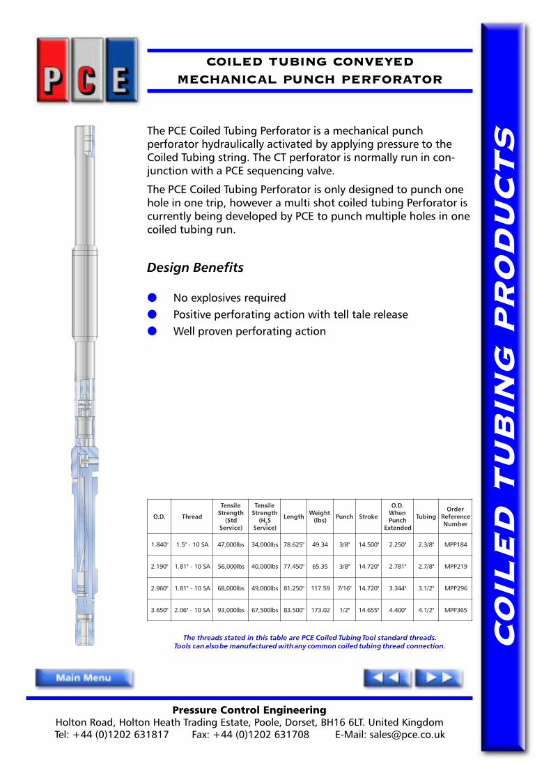
COILED TUBING CONVEYEDMECHANICAL PUNCH PERFORATOR
The PCE Coiled Tubing Perforator is a mechanical punchperforator hydraulically activated by applying pressure to theCoiled Tubing string. The CT perforator is normally run in con-junction with a PCE sequencing valve.
The PCE Coiled Tubing Perforator is only designed to punch onehole in one trip, however a multi shot coiled tubing Perforator iscurrently being developed by PCE to punch multiple holes in onecoiled tubing run.
Design Benefits
● No explosives required● Positive perforating action with tell tale release● Well proven perforating action
The threads stated in this table are PCE Coiled Tubing Tool standard threads.Tools can also be manufactured with any common coiled tubing thread connection.
.D.O daerhT
elisneThtgnertS
dtS()ecivreS
elisneThtgnertS
H( 2S)ecivreS
htgneL thgieW)sbl( hcnuP ekortS
.D.OnehWhcnuP
dednetxE
gnibuTredrO
ecnerefeRrebmuN
"048.1 AS01-"5.1 sbl000,74 sbl000,43 "526.87 43.94 "8/3 "005.41 "052.2 "8/3.2 481PPM
"091.2 AS01-"18.1 sbl000,65 sbl000,04 "054.77 53.56 "8/3 "027.41 "187.2 "8/7.2 912PPM
"069.2 AS01-"18.1 sbl000,86 sbl000,94 "052.18 95.711 "61/7 "027.41 "443.3 "2/1.3 692PPM
"056.3 AS01-"60.2 sbl000,39 sbl005,76 "005.38 20.371 "2/1 "556.41 "004.4 "2/1.4 563PPM

Pressure Control EngineeringHolton Road, Holton Heath Trading Estate, Poole, Dorset, BH16 6LT. United KingdomTel: +44 (0)1202 631817 Fax: +44 (0)1202 631708 E-Mail: [email protected]
CO
ILE
D T
UB
ING
PR
OD
UC
TS
COILED TUBINGB.O.S.S RELEASE JOINT
The PCE B.O.S.S Release Joint or (Ball Operated Safety Shear)allows the release of the Coiled Tubing tool/work string at apredetermined point should the need arise.
The PCE B.O.S.S Release Joint operates on the principle of adropped ball locating on a seat within the tool. Hydraulic pres-sure applied to the tool will activate the release mechanism at apredetermined pressure. Once released, circulation through thecoil is re-established through the upper part of the tool.
The lower part to the release joint can be retrieved using aconventional �GS� Type Running/Pulling Tool or with a PCERelease Joint Retrieval Tool.
Design Features
● Positive "Drop Ball" to release
● Large i.d. through tool
● Conventional fish neck to retrieve the released joint withoptional sealing prong
The threads stated in this table are PCE Coiled Tubing Tool standard threads.Tools can also be manufactured with any common coiled tubing thread connection.
.D.O .D.I daerhT llarevOhtgneL
pU-ekaMhtgneL
llaBesaeleR
lanretnIllaB
ecnaraelC
tiKlaeSredrO
ecnerefeRrebmuN
redrOecnerefeRrebmuN
"786.1 "005.0 AS01-"5.1 "006.51 "057.21 "61/9 "61/7 SK961JRBD 961JRBD
"521.2 "526.0 AS01-"18.1 "001.61 "052.31 "61/11 "61/9 SK212JRBD 212JRBD
"573.2 "218.0 AS01-"18.1 "001.61 "052.31 "8/7 "4/3 SK732JRBD 732JRBD
"521.3 "739.0 AS01-"60.2 "574.61 "526.31 "1 "8/7 SK213JRBD 213JRBD

Pressure Control EngineeringHolton Road, Holton Heath Trading Estate, Poole, Dorset, BH16 6LT. United KingdomTel: +44 (0)1202 631817 Fax: +44 (0)1202 631708 E-Mail: [email protected]
CO
ILE
D T
UB
ING
PR
OD
UC
TS
COILED TUBINGSHEAR RELEASE JOINT (TORQUE - THRU)
The PCE Shear Release Joint allows the parting of the CoiledTubing work string by applied predetermined tension.
The PCE Shear Release Joint was designed for and used primarilyin cement stinger operations as a simple effective emergencyrelease.
The PCE Shear Release Joint incorporates shear screws that canbe used in various combinations to allow a wide range ofpredetermined shear settings.
The released part of the PCE Shear Release Joint can be retrievedusing a �GS� type pulling tool or a PCE Release Joint RetrievalTool.
Design Features
● Simple design● On location adjustable settings● Internal pressure seal● Internal �GS� type fish neck after release● Torque Thru capability
The threads stated in this table are PCE Coiled Tubing Tool standard threads.Tools can also be manufactured with any common coiled tubing thread connection.
lanretnIhsiF'SG'
kceNeziS
.D.O .D.I daerhT llarevOhtgneL
pU-ekaMhtgneL
lanretnIllaB
ecnaraelC
tiKlaeSredrO
ecnerefeRrebmuN
redrOecnerefeRrebmuN
"2 "786.1 "005.0 AS01-"5.1 "008.11 "059.8 "61/7 SK961TJRS 961TJRS
"2 "521.2 "347.0 AS01-"18.1 "005.11 "056.8 "61/11 SK212TJRS 212TJRS
"2/1.2 "573.2 "347.0 AS01-"18.1 "578.11 "520.9 "61/11 SK732TJRS 732TJRS
"2/1.2 "578.2 "052.1 AS01-"60.2 "052.21 "004.9 "8/1.1 SK782TJRS 782TJRS
"3 "521.3 "052.1 AS01-"60.2 "052.21 "004.9 "8/1.1 SK213TJRS 213TJRS
Pressure Control EngineeringHolton Road, Holton Heath Trading Estate, Poole, Dorset, BH16 6LT. United KingdomTel: +44 (0)1202 631817 Fax: +44 (0)1202 631708 E-Mail: [email protected]
CO
ILE
D T
UB
ING
PR
OD
UC
TS
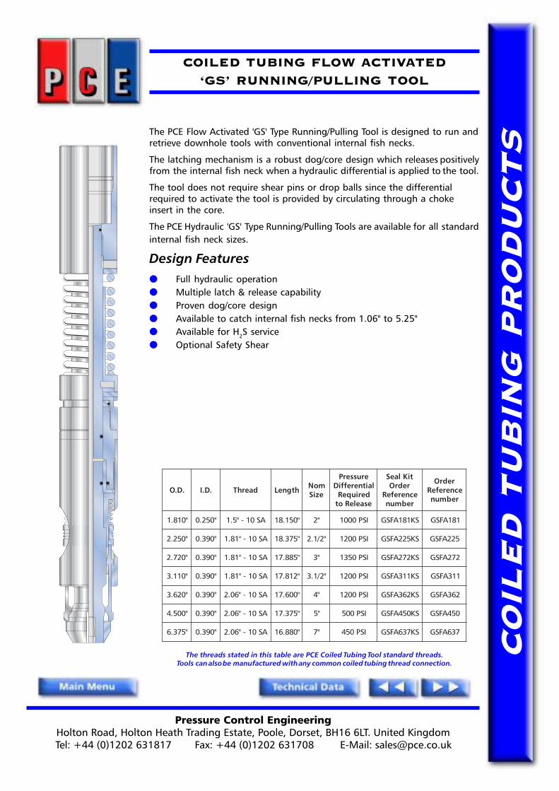
COILED TUBING FLOW ACTIVATED�GS� RUNNING/PULLING TOOL
The PCE Flow Activated 'GS' Type Running/Pulling Tool is designed to run andretrieve downhole tools with conventional internal fish necks.
The latching mechanism is a robust dog/core design which releases positivelyfrom the internal fish neck when a hydraulic differential is applied to the tool.
The tool does not require shear pins or drop balls since the differentialrequired to activate the tool is provided by circulating through a chokeinsert in the core.
The PCE Hydraulic 'GS' Type Running/Pulling Tools are available for all standardinternal fish neck sizes.
Design Features● Full hydraulic operation● Multiple latch & release capability● Proven dog/core design● Available to catch internal fish necks from 1.06" to 5.25"● Available for H2S service● Optional Safety Shear
The threads stated in this table are PCE Coiled Tubing Tool standard threads.Tools can also be manufactured with any common coiled tubing thread connection.
.D.O .D.I daerhT htgneL moNeziS
erusserPlaitnereffiD
deriuqeResaeleRot
tiKlaeSredrO
ecnerefeRrebmun
redrOecnerefeR
rebmun
"018.1 "052.0 AS01-"5.1 "051.81 "2 ISP0001 SK181AFSG 181AFSG
"052.2 "093.0 AS01-"18.1 "573.81 "2/1.2 ISP0021 SK522AFSG 522AFSG
"027.2 "093.0 AS01-"18.1 "588.71 "3 ISP0531 SK272AFSG 272AFSG
"011.3 "093.0 AS01-"18.1 "218.71 "2/1.3 ISP0021 SK113AFSG 113AFSG
"026.3 "093.0 AS01-"60.2 "006.71 "4 ISP0021 SK263AFSG 263AFSG
"005.4 "093.0 AS01-"60.2 "573.71 "5 ISP005 SK054AFSG 054AFSG
"573.6 "093.0 AS01-"60.2 "088.61 "7 ISP054 SK736AFSG 736AFSG
Pressure Control EngineeringHolton Road, Holton Heath Trading Estate, Poole, Dorset, BH16 6LT. United KingdomTel: +44 (0)1202 631817 Fax: +44 (0)1202 631708 E-Mail: [email protected]
CO
ILE
D T
UB
ING
PR
OD
UC
TS
COILED TUBING FLOW ACTIVATED�HEAVY DUTY� RUNNING/PULLING TOOL
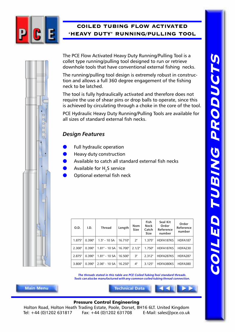
The PCE Flow Activated Heavy Duty Running/Pulling Tool is acollet type running/pulling tool designed to run or retrievedownhole tools that have conventional external fishing necks.
The running/pulling tool design is extremely robust in construc-tion and allows a full 360 degree engagement of the fishingneck to be latched.
The tool is fully hydraulically activated and therefore does notrequire the use of shear pins or drop balls to operate, since thisis achieved by circulating through a choke in the core of the tool.
PCE Hydraulic Heavy Duty Running/Pulling Tools are available forall sizes of standard external fish necks.
Design Features
● Full hydraulic operation● Heavy duty construction● Available to catch all standard external fish necks● Available for H2S service● Optional external fish neck
The threads stated in this table are PCE Coiled Tubing Tool standard threads.Tools can also be manufactured with any common coiled tubing thread connection.
.D.O .D.I daerhT htgneL moNeziS
hsiFkceNhctaC
eziS
tiKlaeSredrO
ecnerefeRrebmun
redrOecnerefeR
rebmun
"578.1 "093.0 AS01-"5.1 "017.61 "2 "573.1 SK781AFDH 781AFDH
"003.2 "093.0 AS01-"18.1 "007.61 "2/1.2 "057.1 SK781AFDH 032AFDH
"578.2 "093.0 AS01-"18.1 "005.61 "3 "213.2 SK782AFDH 782AFDH
"008.3 "093.0 AS01-"60.2 "052.61 "4 "521.3 SK083AFDH 083AFDH

Pressure Control EngineeringHolton Road, Holton Heath Trading Estate, Poole, Dorset, BH16 6LT. United KingdomTel: +44 (0)1202 631817 Fax: +44 (0)1202 631708 E-Mail: [email protected]
CO
ILE
D T
UB
ING
PR
OD
UC
TS
COILED TUBINGRELEASE JOINT RETRIEVAL TOOL
The PCE Release Joint Retrieval Tool is a coiled tubing service tooldesigned to retrieve a Release Joint that has been previouslyactivated.
The heavy duty lugs are designed to engage the standard sizefish neck inside the released joint.
Shear pins facilitate release of the tool from the fish neck ifrequired. The shear pin values are preset at surface to suitoperational restrictions or maximum pull available.
The threads stated in this table are PCE Coiled Tubing Tool standard threads.Tools can also be manufactured with any common coiled tubing thread connection.
.D.O .D.I daerhT
elisneThtgnertS
dtS()ecivreS
elisneThtgnertS
H( 2S)ecivreS
htgneL thgieW)sbl(
lanimoNeziS
redrOecnerefeRrebmuN
"786.1 "052.0 AS01-"5.1 sbl000,45 sbl000,04 "052.41 86.7 "2 961TRJR
"521.2 "052.0 AS01-"18.1 sbl000,67 sbl000,55 "786.41 05.21 "2/1.2 212TRJR
"573.2 "213.0 AS01-"18.1 sbl000,58 sbl000,25 "781.51 88.51 "2/1.2 732TRJR
"521.3 "213.0 AS01-"60.2 sbl000,201 sbl000,47 "003.51 52.72 "3 213TRJR

Pressure Control EngineeringHolton Road, Holton Heath Trading Estate, Poole, Dorset, BH16 6LT. United KingdomTel: +44 (0)1202 631817 Fax: +44 (0)1202 631708 E-Mail: [email protected]
CO
ILE
D T
UB
ING
PR
OD
UC
TS
COILED TUBINGBACK PRESSURE VALVE
The PCE Coiled Tubing Back Pressure Valve is a CT string componentthat provides a circulation path against a predetermined backpressure. It is ideally suited to operations when the hydrostaticpressure within the Coiled Tubing needs to be higher than thepressure in the annulus areas.
The design of the PCE Back Pressure Valve allows for an on-sitedetermination of back pressure to be set at surface. This is achievedwith the use of different ball diameters to increase/decrease thepiston area and pressure required to open the valve.
The PCE Back Pressure Valve assemblies are available in a range ofsizes.
Design Features
● Metal to metal sealing
● Ball & cage design protects components from 'wash out'
● Site adjustable settings
● Simple design allows easy maintenance
*Different ball sizes can be supplied to set the opening pressurefrom 500-1000 P.S.I pressure differential
The threads stated in this table are PCE Coiled Tubing Tool standard threads.Tools can also be manufactured with any common coiled tubing thread connection.
.D.O .D.I daerhT llarevOhtgneL
pU-ekaMhtgneL
*llaBeziS
redrOecnerefeRrebmuN
"786.1 A/N AS01-"5.1 "034.31 "085.01 "8/7-"2/1 961AVPB
"521.2 A/N AS01-"18.1 "072.31 "024.01 "1-"2/1 212AVPB
"573.2 A/N AS01-"18.1 "072.31 "024.01 "1-"2/1 732AVPB
"521.3 A/N AS01-"60.2 "030.41 "081.11 "2/1.1-"4/3 213AVPB

Pressure Control EngineeringHolton Road, Holton Heath Trading Estate, Poole, Dorset, BH16 6LT. United KingdomTel: +44 (0)1202 631817 Fax: +44 (0)1202 631708 E-Mail: [email protected]
CO
ILE
D T
UB
ING
PR
OD
UC
TS
COILED TUBINGBALL CHECK VALVE
The PCE Ball Check Valve is a standard coiled tubing stringcomponent. It�s use in a toolstring provides a means ofpreventing the back flow of fluids into the coiled tubing in theevent of failure or damage to the surface equipment.
Ball Check valves are used when devices such as balls and dartsdo not need to pass through the valve. In the event of a ball ordart needing to be dropped a Flapper Valve must be used.
Design Features
● Large flow area
● Easy redress
● Metal to metal sealing
The threads stated in this table are PCE Coiled Tubing Tool standard threads.Tools can also be manufactured with any common coiled tubing thread connection.
.D.O .D.I daerhT llarevOhtgneL
pU-ekaMhtgneL
redrOecnerefeRrebmuN
"786.1 A/N AS01-"5.1 "136.11 "187.8 961VCBS
"521.2 A/N AS01-"18.1 "787.11 "739.8 212VCBS
"573.2 A/N AS01-"18.1 "787.11 "739.8 732VCBS
"521.3 A/N AS01-"60.2 "005.21 "056.9 213VCBS
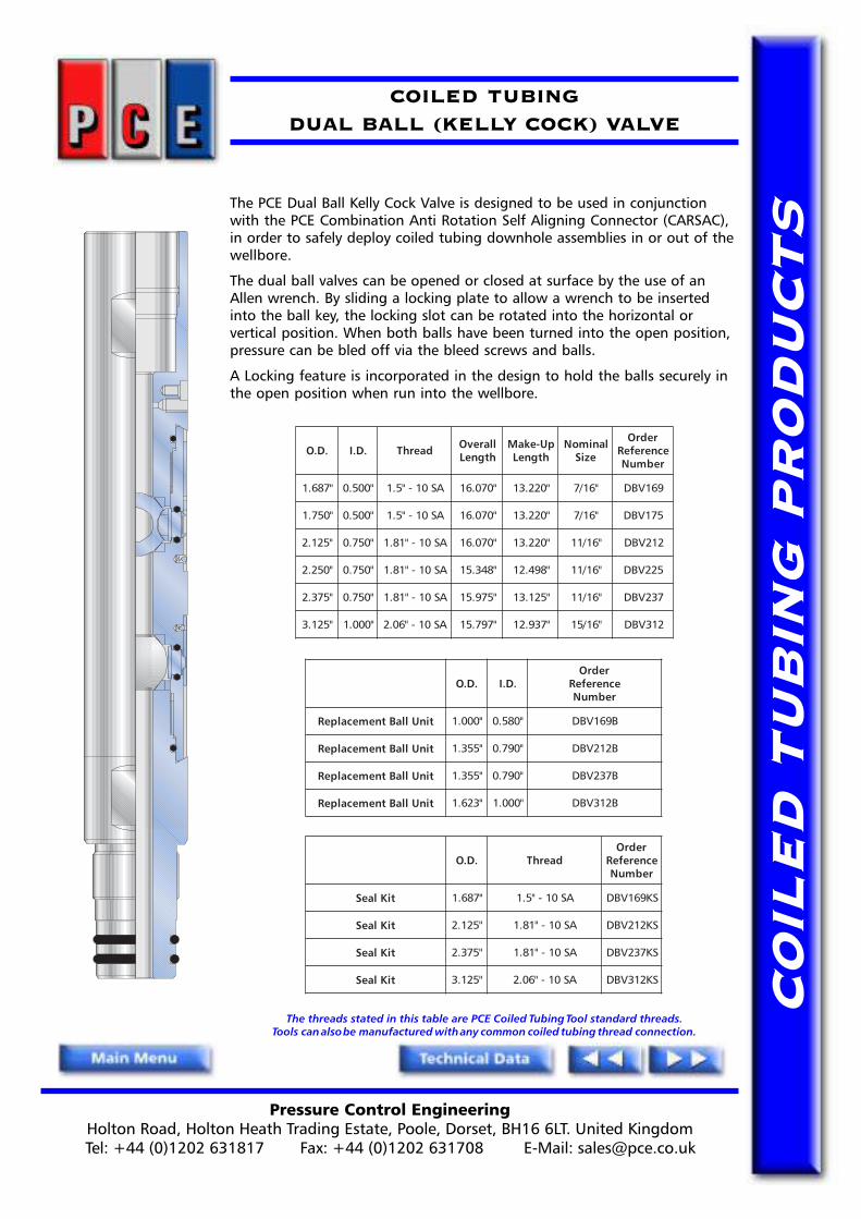
Pressure Control EngineeringHolton Road, Holton Heath Trading Estate, Poole, Dorset, BH16 6LT. United KingdomTel: +44 (0)1202 631817 Fax: +44 (0)1202 631708 E-Mail: [email protected]
CO
ILE
D T
UB
ING
PR
OD
UC
TS
COILED TUBINGDUAL BALL (KELLY COCK) VALVE
The PCE Dual Ball Kelly Cock Valve is designed to be used in conjunctionwith the PCE Combination Anti Rotation Self Aligning Connector (CARSAC),in order to safely deploy coiled tubing downhole assemblies in or out of thewellbore.
The dual ball valves can be opened or closed at surface by the use of anAllen wrench. By sliding a locking plate to allow a wrench to be insertedinto the ball key, the locking slot can be rotated into the horizontal orvertical position. When both balls have been turned into the open position,pressure can be bled off via the bleed screws and balls.
A Locking feature is incorporated in the design to hold the balls securely inthe open position when run into the wellbore.
The threads stated in this table are PCE Coiled Tubing Tool standard threads.Tools can also be manufactured with any common coiled tubing thread connection.
.D.O .D.I daerhT llarevOhtgneL
pU-ekaMhtgneL
lanimoNeziS
redrOecnerefeRrebmuN
"786.1 "005.0 AS01-"5.1 "070.61 "022.31 "61/7 961VBD
"057.1 "005.0 AS01-"5.1 "070.61 "022.31 "61/7 571VBD
"521.2 "057.0 AS01-"18.1 "070.61 "022.31 "61/11 212VBD
"052.2 "057.0 AS01-"18.1 "843.51 "894.21 "61/11 522VBD
"573.2 "057.0 AS01-"18.1 "579.51 "521.31 "61/11 732VBD
"521.3 "000.1 AS01-"60.2 "797.51 "739.21 "61/51 213VBD
.D.O .D.IredrO
ecnerefeRrebmuN
tinUllaBtnemecalpeR "000.1 "085.0 B961VBD
tinUllaBtnemecalpeR "553.1 "097.0 B212VBD
tinUllaBtnemecalpeR "553.1 "097.0 B732VBD
tinUllaBtnemecalpeR "326.1 "000.1 B213VBD
.D.O daerhTredrO
ecnerefeRrebmuN
tiKlaeS "786.1 AS01-"5.1 SK961VBD
tiKlaeS "521.2 AS01-"18.1 SK212VBD
tiKlaeS "573.2 AS01-"18.1 SK732VBD
tiKlaeS "521.3 AS01-"60.2 SK213VBD

Pressure Control EngineeringHolton Road, Holton Heath Trading Estate, Poole, Dorset, BH16 6LT. United KingdomTel: +44 (0)1202 631817 Fax: +44 (0)1202 631708 E-Mail: [email protected]
CO
ILE
D T
UB
ING
PR
OD
UC
TS
COILED TUBINGTWIN FLAPPER CHECK VALVE
The PCE Twin Flapper Check Valve is a standard Coiled Tubing stringcomponent. It's use provides a means of preventing the back flow ofwell fluids into the Coiled Tubing in the event of failure or damage tothe Coiled Tubing string or surface equipment.
The design of the PCE Twin Flapper Check Valve incorporates a dualsealing system in each flapper assembly for increased safety. A teflonseat provides the primary low pressure seal, while at higher pressuresthe flappers seat on a metal to metal sealing arrangement.
Design Features● Dual sealing in each flapper cartridge i.e. low pressure
teflon seat/seal and high pressure full metal to metal seat/seal.● Full bore fluid passage for balls, darts & plugs.● Removable flapper cartridges
The threads stated in this table are PCE Coiled Tubing Tool standard threads.Tools can also be manufactured with any common coiled tubing thread connection.
.D.O .D.I daerhT llarevOhtgneL
pU-ekaMhtgneL
thgieW)sbl(
lanretnIllaB
ecnaraelC
tiKlaeSredrO
ecnerefeRrebmuN
redrOecnerefeRrebmuN
"786.1 "057.0 AS01-"5.1 "573.61 "135.31 61.8 "61/11 SK961VCFT 961VCFT
"521.2 "198.0 AS01-"18.1 "526.41 "057.11 00.01 "61/31 SK212VCFT 212VCFT
"573.2 "130.1 AS01-"18.1 "573.61 "005.31 53.31 "1 SK732VCFT 732VCFT
"521.3 "573.1 AS01-"60.2 "219.71 "260.51 05.42 "4/1.1 SK213VCFT 213VCFT
YLBMESSAEVLAVREPPALFTNEMECALPER
.D.I .D.O stnetnoCtiK ecnerefeRredrOrebmuN
"057.0 "573.1E.F.T.PdelliFmunedbyloM%2,ssalG%32:laeS
leetSsselniatSHP4-71:reppalF&taeS,ydoB
057XlenocnI:niPegniH
961CVC
"198.0 "115.1 212CVC
"130.1 "308.1 732CVC
"573.1 "042.2 213CVC

Pressure Control EngineeringHolton Road, Holton Heath Trading Estate, Poole, Dorset, BH16 6LT. United KingdomTel: +44 (0)1202 631817 Fax: +44 (0)1202 631708 E-Mail: [email protected]
CO
ILE
D T
UB
ING
PR
OD
UC
TS
COILED TUBINGTWIN FLAPPER CHECK VALVE WITH BYPASS
The PCE Twin Flapper Check Valve with Bypass is a Coiled Tubing stringcomponent with the added facility for use in logging cable bypassoperations. It's use provides a means of preventing the back flow ofwell fluids into the Coiled Tubing in the event of failure or damage tothe Coiled Tubing string or surface equipment.
The design of the PCE Twin Flapper Check Valve incorporates a dualsealing system in each flapper assembly for increased safety. A teflonseat provides the primary low pressure seal, while at higher pressures,the flappers seat on a metal to metal sealing arrangement.
The PCE Twin Flapper Check Valve assemblies with Cable Bypass areavailable in a range of sizes.
Design Benefits
● Dual sealing in each flapper cartridge i.e. low pressure teflonseat/seal and high pressure full metal to metal seat/seal
● Fluid passage for balls, darts & plugs.
● Removable flapper cartridges
● Logging cable bypass facility
The threads stated in this table are PCE Coiled Tubing Tool standard threads.Tools can also be manufactured with any common coiled tubing thread connection.
.D.O .D.I daerhTelisneThtgnertS
)ecivreSdtS(
elisneThtgnertS
H( 2 )ecivreSS
llarevOhtgneL
pU-ekaMhtgneL
thgieW)sbl(
lanretnIllaB
ecnaraelC
elbaCssap-yB
xaM
redrOecnerefeRrebmuN
"521.2 "005.0 AS01-"18.1 sbl000,501 sbl000,08 "983.51 "935.21 82.11 "61/7 "61/5 B212VCFT
"005.2 "005.0 AS01-"18.1 sbl000,511 sbl000,38 "983.51 "935.21 78.31 "61/7 "61/7 B052VCFT
"521.3 "057.0 AS01-"60.2 sbl000,031 sbl000,59 "730.81 "781.51 95.82 "61/11 "61/11 B213VCFT

Pressure Control EngineeringHolton Road, Holton Heath Trading Estate, Poole, Dorset, BH16 6LT. United KingdomTel: +44 (0)1202 631817 Fax: +44 (0)1202 631708 E-Mail: [email protected]
CO
ILE
D T
UB
ING
PR
OD
UC
TS
COILED TUBINGSEQUENCING TOOL
The PCE Flow Activated Sequencing Tool is designed for actuating downholeCT tools at a predetermined pressure.
The design of the PCE Flow Activated Sequencing Tool allows normal circula-tion, whilst running into the well, up to a given pump volume and thereforepressure differential at the tool. Once the design differential pressure isexceeded, the flow path is closed and diverted into the internal bore of thetoolstring, thereby enabling hydraulic activation of any tools in the lowerend of the tool string.
The PCE Flow Activated Sequencing Tools are available in a range of sizes.
Design Features
● Allows circulation whilst running into well bore
● Flow activated, no drop ball required
● The closing differential pressure can be field adjusted by simply
placing an internal 'O' ring in one of four positions
The threads stated in this table are PCE Coiled Tubing Tool standard threads.Tools can also be manufactured with any common coiled tubing thread connection.
.D.O daerhT llarevOhtgneL
pU-ekaMhtgneL
thgieW)sbl(
tiKlaeSredrO
ecnerefeRrebmuN
redrOecnerefeRrebmuN
"786.1 AS01-"5.1 "347.61 "398.31 81.8 SK961V4QS 961V4QS
"057.1 AS01-"5.1 "347.61 "398.31 24.8 SK571V4QS 571V4QS
"521.2 AS01-"18.1 "005.51 "056.21 51.11 SK212V4QS 212V4QS
"052.2 AS01-"18.1 "907.51 "958.21 19.21 SK522V4QS 522V4QS
"573.2 AS01-"18.1 "014.51 "065.21 81.41 SK732V4QS 732V4QS
"521.3 AS01-"18.1 "842.51 "893.21 61.42 SK213V4QS 213V4QS

Pressure Control EngineeringHolton Road, Holton Heath Trading Estate, Poole, Dorset, BH16 6LT. United KingdomTel: +44 (0)1202 631817 Fax: +44 (0)1202 631708 E-Mail: [email protected]
CO
ILE
D T
UB
ING
PR
OD
UC
TS
COILED TUBINGFLOW ACTIVATED SHIFTING TOOL
The PCE Flow Activated Shifting Tool is designed to be used as a worktool for opening and closing sliding sleeves.
The normally closed shifting tool is flow activated and therefore doesnot require the use of drop balls to activate it. The shifting tool bydesign can be used to either open or close sliding sleeves.
The PCE Flow Activated Shifting Tools are available to suit all sizes andmakes of Sliding Sleeves and can be supplied with either positive orselective keys.
Design Benefits● Flow activated (No drop balls required)
● Dual action for opening or closing sliding sleeves
● Positive or selective key options
● Available for H2S service
● Optional external fish neck
The threads stated in this table are PCE Coiled Tubing Tool standard threads.Tools can also be manufactured with any common coiled tubing thread connection.
.D.O .D.I daerhT
elisneThtgnertS
dtS()ecivreS
elisneThtgnertS
H( 2S)ecivreS
llarevOhtgneL
pU-ekaMhtgneL
thgieW)sbl(
DSSeziS
hsiFkceN
redrOecnerefeRrebmuN
"061.2 "093.0 AS01-"5.1 sbl000,65 sbl000,14 "057.52 "009.22 35.51 "313.2 "313.2 3132AFTS
"035.2 "093.0 AS01-"5.1 sbl000,76 sbl000,94 "730.62 "781.32 21.12 "265.2 "313.2 2652AFTS
"027.2 "093.0 AS01-"18.1 sbl000,68 sbl005,26 "084.62 "036.32 06.33 "057.2 "313.2 0572AFTS
"027.2 "093.0 AS01-"18.1 sbl000,09 sbl005,56 "084.62 "036.32 01.43 "318.2 "313.2 3182AFTS
"060.3 "005.0 AS01-"18.1 sbl000,09 sbl005,56 "053.62 "005.32 45.83 "521.3 "313.2 5213AFTS
"052.3 "734.0 AS01-"18.1 sbl000,49 sbl005,86 "527.62 "578.32 02.54 "313.3 "313.2 3133AFTS
"014.3 "005.0 AS01-"18.1 sbl000,49 sbl005,86 "058.62 "000.42 33.94 "734.3 "313.2 7343AFTS
"066.3 "734.0 AS01-"18.1 sbl000,001 sbl005,27 "052.22 "004.91 50.44 "886.3 "521.3 8863AFTS
"066.3 "005.0 AS01-"18.1 sbl000,002 sbl000,641 "035.72 "086.42 06.85 "318.3 "521.3 3183AFTS
"027.3 "005.0 AS01-"60.2 sbl000,112 sbl000,451 "053.72 "005.42 00.47 "521.4 "521.3 5214AFTS
"052.4 "005.0 AS01-"60.2 sbl000,642 sbl005,971 "525.82 "576.52 56.101 "313.4 "521.3 3134AFTS
"052.4 "005.0 AS01-"60.2 sbl000,982 sbl000,112 "713.72 "576.42 78.69 "265.4 "521.3 2654AFTS

Pressure Control EngineeringHolton Road, Holton Heath Trading Estate, Poole, Dorset, BH16 6LT. United KingdomTel: +44 (0)1202 631817 Fax: +44 (0)1202 631708 E-Mail: [email protected]
CO
ILE
D T
UB
ING
PR
OD
UC
TS
PCE COILED TUBING FLOW ACTIVATEDDOUBLE ENDED SELECTIVE SHIFTING TOOL
The PCE Coiled Tubing Double Ended Selective Shifting Tool (DESST) hasbeen designed specifically to selectively shift PCE, Otis, Camco, Baker slidingsleeves (SSD�s) in horizontal well bores.
The DESST shifting keys are normally retracted during the running operationand are hydraulically flow activated to the open shift position by increasingsurface pump volume and therefore pressure at the downhole location ofthe DESST and SSD. The DESST can selectively open or close multiple SSD�sin a single CT trip.
Design Benefits● Flow activated (No drop balls required)
● Dual action for opening or closing sliding sleeves
● Positive or selective key options
● Available for H2S service
● Optional external fish neck
The Threads stated in this table are PCE Coiled Tubing Tool standard threads.Tools can also be manufactured with any common coiled tubing thread connection.
.D.O .D.I daerhT
elisneThtgnertS
dtS()ecivreS
elisneThtgnertS
H( 2S)ecivreS
htgneL thgieW)sbl(
DSSeziS
hsiFkceN
redrOecnerefeRrebmuN
"061.2 "093.0 AS01-"5.1 sbl000,65 sbl000,14 "521.53 58.42 "313.2 "313.2 3132AFTSD
"035.2 "093.0 AS01-"5.1 sbl000,76 sbl000,94 "005.43 97.33 "265.2 "313.2 2652AFTSD
"027.2 "093.0 AS01-"18.1 sbl000,68 sbl005,26 "573.63 67.35 "057.2 "313.2 0572AFTSD
"027.2 "093.0 AS01-"18.1 sbl000,09 sbl005,56 "578.73 65.45 "318.2 "313.2 3182AFTSD
"060.3 "005.0 AS01-"18.1 sbl000,09 sbl005,56 "057.83 66.16 "521.3 "313.2 5213AFTSD
"052.3 "734.0 AS01-"18.1 sbl000,49 sbl005,86 "265.83 23.27 "313.3 "313.2 3133AFTSD
"014.3 "005.0 AS01-"18.1 sbl000,49 sbl005,86 "781.93 39.87 "734.3 "313.2 7343AFTSD
"066.3 "734.0 AS01-"18.1 sbl000,001 sbl005,27 "405.33 84.07 "886.3 "521.3 8863AFTSD
"066.3 "005.0 AS01-"18.1 sbl000,002 sbl000,641 "052.83 67.39 "318.3 "521.3 3183AFTSD
"027.3 "005.0 AS01-"60.2 sbl000,112 sbl000,451 "006.93 93.811 "521.4 "521.3 5214AFTSD
"052.4 "005.0 AS01-"60.2 sbl000,642 sbl005,971 "005.14 46.261 "313.4 "521.3 3134AFTSD
"052.4 "005.0 AS01-"60.2 sbl000,982 sbl000,112 "065.14 99.451 "265.4 "521.3 2654AFTSD

Pressure Control EngineeringHolton Road, Holton Heath Trading Estate, Poole, Dorset, BH16 6LT. United KingdomTel: +44 (0)1202 631817 Fax: +44 (0)1202 631708 E-Mail: [email protected]
CO
ILE
D T
UB
ING
PR
OD
UC
TS
COILED TUBINGSTRAIGHT BAR
The PCE Straight Bar is designed to be added to the CoiledTubing work string as necessary to add extra mass when carryingout running, pulling and fishing operations.
The PCE Straight Bar has a full flow through bore allowing thepassage of darts or drop balls and is available in any specificlength.
The PCE Straight Bars are available in a range of sizes.
Design Benefits
● Full flow through bore
The threads stated in this table are PCE Coiled Tubing Tool standard threads.Tools can also be manufactured with any common coiled tubing thread connection.
.D.O .D.I daerhTelisneThtgnertS
)ecivreSdtS(
elisneThtgnertS
H( 2 )ecivreSS
pU-ekaMhtgneL
thgieW)sbl(
lanretnIllaB
ecnaraelC
redrOecnerefeRrebmuN
"786.1 "057.0 AS01-"5.1 sbl000,06 sbl000,44 "63 72.81 "61/11 63x961BS
"786.1 "057.0 AS01-"5.1 sbl000,06 sbl000,44 "06 54.03 "61/11 06x961BS
"057.1 "057.0 AS01-"5.1 sbl000,06 sbl000,44 "63 00.02 "61/11 63x571BS
"057.1 "057.0 AS01-"5.1 sbl000,06 sbl000,44 "06 43.33 "61/11 06x571BS
"521.2 "000.1 AS01-"18.1 sbl000,061 sbl000,611 "63 31.82 "61/51 63x212BS
"521.2 "000.1 AS01-"18.1 sbl000,061 sbl000,611 "06 88.64 "61/51 06x212BS
"052.2 "000.1 AS01-"18.1 sbl000,061 sbl000,611 "63 15.23 "61/51 63x522BS
"052.2 "000.1 AS01-"18.1 sbl000,061 sbl000,611 "06 81.45 "61/51 06x522BS
"573.2 "000.1 AS01-"18.1 sbl000,061 sbl000,611 "63 31.73 "61/51 63x732BS
"573.2 "000.1 AS01-"18.1 sbl000,061 sbl000,611 "06 98.16 "61/51 06x732BS
"521.3 "005.1 AS01-"60.2 sbl000,831 sbl000,101 "63 41.06 "4/1.1 63x213BS
"521.3 "005.1 AS01-"60.2 sbl000,831 sbl000,101 "06 32.001 "4/1.1 06x213BS

Pressure Control EngineeringHolton Road, Holton Heath Trading Estate, Poole, Dorset, BH16 6LT. United KingdomTel: +44 (0)1202 631817 Fax: +44 (0)1202 631708 E-Mail: [email protected]
CO
ILE
D T
UB
ING
PR
OD
UC
TS
COILED TUBING FLOW ACTIVATEDMULTI-SHOT TUBING END LOCATOR
The PCE Flow Activated Multi-Shot Tubing End Locator is designed to beused as part of the standard tool string assembly to allow location of theend of the production tubing for depth correlation.
The Tubing End Locator is flow activated and therefore offers the ability to're-tag' the end of the tubing as many times as required without the need toretract from the well for redress.
The tool is flow activated by surface pump volume and pressure and theforce required to pull through the tubing end can therefore be infinitelyvaried.
The PCE Hydraulic Tubing End Locator are available in a range of toolstringsizes, with fingers to suit the tubing i.d. as required.
Design Benefits
● Design allows multiple 're-tagging'
● Fingers retract within body diameter
● Flow or drop ball activated
● Optional external fish neck
The threads stated in this table are PCE Coiled Tubing Tool standard threads.Tools can also be manufactured with any common coiled tubing thread connection.
.D.O .D.I daerhT
elisneThtgnertS
dtS()ecivreS
elisneThtgnertS
H( 2S)ecivreS
llarevOhtgneL
pU-ekaMhtgneL
thgieW)sbl(
regniFgninepOerusserP
)ISP(
sregniFelbaliavA
rof
redrOecnerefeRrebmuN
"786.1 "052.0 AS01-"5.1 sbl000,83 sbl000,72 "006.12 "057.81 05.01 isp005 5.4/"5.3gnibuT 571LTSM
"521.2 "052.0 AS01-"18.1 sbl000.83 sbl000,72 "037.12 "088.81 25.61 isp005 "5.4/"5.3gnibuT 212LTSM
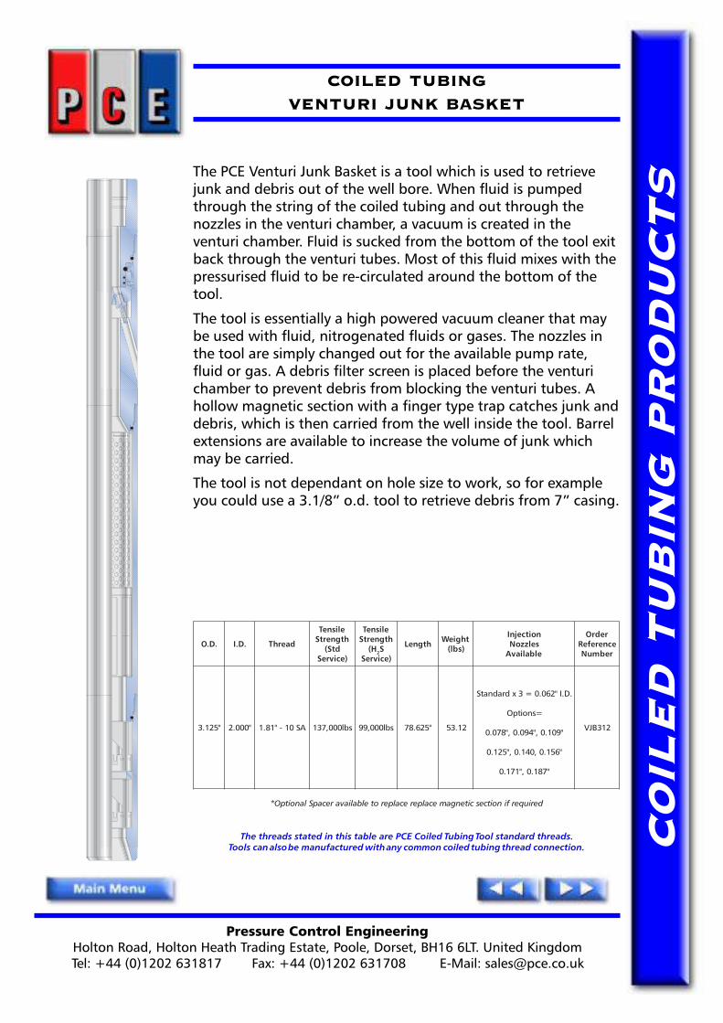
Pressure Control EngineeringHolton Road, Holton Heath Trading Estate, Poole, Dorset, BH16 6LT. United KingdomTel: +44 (0)1202 631817 Fax: +44 (0)1202 631708 E-Mail: [email protected]
CO
ILE
D T
UB
ING
PR
OD
UC
TS
COILED TUBINGVENTURI JUNK BASKET
The PCE Venturi Junk Basket is a tool which is used to retrievejunk and debris out of the well bore. When fluid is pumpedthrough the string of the coiled tubing and out through thenozzles in the venturi chamber, a vacuum is created in theventuri chamber. Fluid is sucked from the bottom of the tool exitback through the venturi tubes. Most of this fluid mixes with thepressurised fluid to be re-circulated around the bottom of thetool.
The tool is essentially a high powered vacuum cleaner that maybe used with fluid, nitrogenated fluids or gases. The nozzles inthe tool are simply changed out for the available pump rate,fluid or gas. A debris filter screen is placed before the venturichamber to prevent debris from blocking the venturi tubes. Ahollow magnetic section with a finger type trap catches junk anddebris, which is then carried from the well inside the tool. Barrelextensions are available to increase the volume of junk whichmay be carried.
The tool is not dependant on hole size to work, so for exampleyou could use a 3.1/8� o.d. tool to retrieve debris from 7� casing.
The threads stated in this table are PCE Coiled Tubing Tool standard threads.Tools can also be manufactured with any common coiled tubing thread connection.
.D.O .D.I daerhT
elisneThtgnertS
dtS()ecivreS
elisneThtgnertS
H( 2S)ecivreS
htgneL thgieW)sbl(
noitcejnIselzzoNelbaliavA
redrOecnerefeRrebmuN
"521.3 "000.2 AS01-"18.1 sbl000,731 sbl000,99 "526.87 21.35
.D.I"260.0=3xdradnatS
=snoitpO
"901.0,"490.0,"870.0
"651.0,041.0,"521.0
"781.0,"171.0
213BJV
deriuqerfinoitcescitengamecalperecalperotelbaliavarecapSlanoitpO*
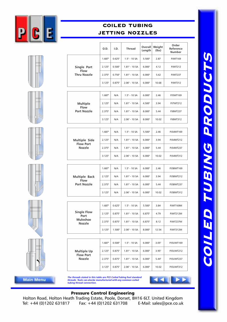
Pressure Control EngineeringHolton Road, Holton Heath Trading Estate, Poole, Dorset, BH16 6LT. United KingdomTel: +44 (0)1202 631817 Fax: +44 (0)1202 631708 E-Mail: [email protected]
CO
ILE
D T
UB
ING
PR
OD
UC
TS
COILED TUBINGJETTING NOZZLES
The threads stated in this table are PCE Coiled Tubing Tool standardthreads. Tools can also be manufactured with any common coiledtubing thread connection.
.D.O .D.I daerhT llarevOhtgneL
thgieW)sbl(
redrOecnerefeRrebmuN
troPelgniSwolF
elzzoNurhT
"786.1 "526.0 AS01-"5.1 "005.5 78.2 961TWJP
"521.2 "005.0 AS01-"18.1 "000.6 21.4 212TWJP
"573.2 "057.0 AS01-"18.1 "000.6 26.5 732TWJP
"521.3 "578.0 AS01-"60.2 "000.6 86.01 213TWJP
elpitluMwolF
elzzoNtroP
"786.1 A/N AS01-"5.1 "000.6 64.2 961TW5JP
"521.2 A/N AS01-"18.1 "005.4 49.3 212TW7JP
"573.2 A/N AS01-"18.1 "000.8 44.5 732TW8JP
"521.3 A/N AS01-"60.2 "000.8 20.01 213TW8JP
ediSelpitluMtroPwolF
elzzoN
"786.1 A/N AS01-"5.1 "005.5 64.2 961TW4SJP
"521.2 A/N AS01-"18.1 "000.6 49.3 212TW4SJP
"573.2 A/N AS01-"18.1 "000.6 44.5 732TW4SJP
"521.3 A/N AS01-"60.2 "000.6 20.01 213TW4SJP
kcaBelpitluMwolF
elzzoNtroP
"786.1 A/N AS01-"5.1 "000.6 64.2 961TWB5JP
"521.2 A/N AS01-"18.1 "000.6 49.3 212TWB5JP
"573.2 A/N AS01-"18.1 "000.6 44.5 732TWB5JP
"521.3 A/N AS01-"60.2 "000.6 20.01 213TWB5JP
wolFelgniStroP
eohseluMelzzoN
"786.1 "526.0 AS01-"5.1 "005.5 48.3 M961TWJP
"521.2 "578.0 AS01-"18.1 "578.6 97.4 M212TWJP
"573.2 "578.0 AS01-"18.1 "578.6 21.8 M732TWJP
"521.3 "005.1 AS01-"60.2 "000.8 45.21 M213TWJP
pUelpitluMtroPwolF
elzzoN
"786.1 "005.0 AS01-"5.1 "000.6 "50.3 961TWU5JP
"521.2 "578.0 AS01-"18.1 "000.6 "59.3 212TWU5JP
"573.2 "578.0 AS01-"18.1 "000.6 "44.5 732TWU5JP
"521.3 "578.0 AS01-"60.2 "000.6 20.01 213TWU5JP

Pressure Control EngineeringHolton Road, Holton Heath Trading Estate, Poole, Dorset, BH16 6LT. United KingdomTel: +44 (0)1202 631817 Fax: +44 (0)1202 631708 E-Mail: [email protected]
CO
ILE
D T
UB
ING
PR
OD
UC
TS
COILED TUBINGMULTI-JET WASH TOOL
The PCE Coiled Tubing Multi-Jet Wash Tool is a non-rotationalwash tool with simple grub screw nozzles that are fieldadjustable.
It is normally used in conjunction with the PCE Flow ActivatedHydraulic Jetting Indexing Tool.
The PCE Multi-Jet Wash Tools are available a range of sizes.
Design Benefits
● Simple and robust construction● Easily field redressed
The threads stated in this table are PCE Coiled Tubing Tool standard threads.Tools can also be manufactured with any common coiled tubing thread connection.
.D.O daerhT llarevOhtgneL
pU-ekaMhtgneL
gnitteJeloHelzzoN31xretemaiD
thgieW)sbl(
redrOecnerefeRrebmuN
"057.1 AS01-"5.1 "023.7 "023.7 "61/3 58.2 571TWJM
"521.2 AS01-"18.1 "045.7 "045.7 "61/3 98.3 212TWJM
"573.2 AS01-"18.1 "016.7 "016.7 "61/3 83.6 732TWJM
"005.2 AS01-"18.1 "016.7 "016.7 "61/3 58.6 052TWJM
"578.2 AS01-"60.2 "000.8 "000.8 "61/3 29.8 782TWJM
"521.3 AS01-"60.2 "000.9 "000.9 "61/3 45.11 213TWJM

Pressure Control EngineeringHolton Road, Holton Heath Trading Estate, Poole, Dorset, BH16 6LT. United KingdomTel: +44 (0)1202 631817 Fax: +44 (0)1202 631708 E-Mail: [email protected]
CO
ILE
D T
UB
ING
PR
OD
UC
TS
COILED TUBINGROTARY JET WASH TOOL
The PCE Rotary Jet Wash Tool is designed to be used for both jettingand circulating operations when cleaning and washing the inside ofthe tubing. It can also be used to assist in motivating the CoiledTubing string both in and out of the well.
The design of the PCE Rotary Jet Wash Tool works on the principal ofapplied fluid pressure causing the nozzle to rotate and jet the fluidagainst the tubing wall in a full 360 degree rotating action.
The PCE Rotary Jet Wash Tools are available in a range of sizes.
Design Features
● Forward and reverse jetting
● Numerous jetting options
● Simple design
The threads stated in this table are PCE Coiled Tubing Tool standard threads.Tools can also be manufactured with any common coiled tubing thread connection.
.D.O .D.I daerhT llarevOhtgneL
gnitteJeloHelzzoN21xretemaiD
thgieW)sbl(
redrOecnereferrebmun
"786.1 "213.0 AS01-"5.1 "052.8 1x6MeloHaiD)mm2("46/5 45.3 961TWS
"057.1 "213.0 AS01-"5.1 "052.8 1x6MeloHaiD)mm2("46/5 48.3 571TWS
"521.2 "057.0 AS01-"18.1 "026.8 1x6MeloHaiD)mm2("46/5 67.5 212TWS
"573.2 "057.0 AS01-"18.1 "026.8 1x6MeloHaiD)mm2("46/5 31.6 732TWS
"521.3 "578.0 AS01-"60.2 "083.01 1x6MeloHaiD)mm2("46/5 67.41 213TWS

PPPRESSURE CONTROLENGINEERING
Pressure Control EngineeringHolton Road, Holton Heath Trading Estate, Poole, Dorset, BH16 6LT. United Kingdom
Tel: +44 (0)1202 631817 Fax: +44 (0)1202 631708 E-Mail: [email protected]
TE
CH
NIC
AL
MA
NU
AL
Coiled TubingBurst Disc
Circulation Sub
PCE
CT
Burs
t D
isc
Cir
cula
tion
Sub
TM
. Pag
e 1o
f 3

TE
CH
NIC
AL
MA
NU
AL
PCE COILED TUBINGBURST DISC CIRCULATION SUB
INTRODUCTION / OPERATION
The PCE Burst Disc Circulation Sub is a standard coiled tubing tool string components that isused in conjunction with tools that require drop balls etc., that need to be circulated intothe coiled tubing.
The PCE Burst Disc Circulation Sub is incorporated into the coiled tubing tool string justbelow the tool that requires a drop ball. Should for any reason circulation be lost due to adown hole restriction, a predetermined pressure applied to the coil will burst the disc in thesub and re-establish circulation.
ASSEMBLY
1) Ensure all parts are clean and lightly oiled and that all 'O'rings are greased.
2) Install 'O'rings (5) onto the thread of Body (1).
3) Check that you have the correctly rated Rupture Disc (2), (they should be accompaniedby a tally plate with the correct rating on it), and place into the side port in Body (1).The spherical side of the disc should be facing outwards.
4) With the shouldered side of the Hold Down Ring (3) down, place it over the top of therupture disc (2). (The spherical part of Rupture Disc (2) should be visible through thecentre of hold down ring).
5) Make up Hold Down Screw (4) into the side port in Body (1) and torque to 50ft/lbs.This should now be retaining both the Rupture Disc (2), and the Hold Down Ring.
PCE
CT
Burs
t D
isc
Cir
cula
tion
Sub
TM
. Pag
e 2
of 3
.D.O .D.I daerhT
elisneThtgnertS
dtS()ecivreS
elisneThtgnertS
H( 2S)ecivreS
llarevOhtgneL
pU-ekaMhtgneL
thgieW)sbl(
lanretnIllaB
ecnaraelC
talF"2/1csiDtsruB
erusserP)ISP(
redrOecnerefeRrebmuN
"786.1 "604.0 AS01-"5.1 sbl005,34 sbl006,13 "005.7 "056.4 77.2 "8/3 0884 961VCPO
"057.1 "604.0 AS01-"5.1 sbl000,95 sbl000,34 "005.7 "056.4 99.2 "8/3 0884 571VCPO
"521.2 "578.0 AS01-"18.1 sbl000,88 sbl000,46 "000.8 "051.5 92.4 "61/31 0884 212VCPO
"573.2 "578.0 AS01-"18.1 sbl000,49 sbl000,86 "000.8 "051.5 88.4 "61/31 0884 732VCPO
"521.3 "000.1 AS01-"60.2 sbl000,831 sbl000,001 "058.7 "000.5 79.8 "61/51 0884 213VCPO
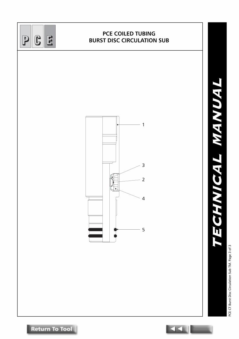
TE
CH
NIC
AL
MA
NU
AL
1
2
3
4
5
PCE COILED TUBINGBURST DISC CIRCULATION SUB
PCE
CT
Burs
t D
isc
Cir
cula
tion
Sub
TM
. Pag
e 3
of 3

PPPRESSURE CONTROLENGINEERING
Pressure Control EngineeringHolton Road, Holton Heath Trading Estate, Poole, Dorset, BH16 6LT. United Kingdom
Tel: +44 (0)1202 631817 Fax: +44 (0)1202 631708 E-Mail: [email protected]
TE
CH
NIC
AL
MA
NU
AL
PCE Coiled TubingBall Activated
Circulation Valve
PCE
CT
Ball
Act
ivat
ed C
ircu
lati
on V
alve
TM
. Pag
e 1
of 3

TE
CH
NIC
AL
MA
NU
AL
PCE COILED TUBING BALL ACTIVATEDCIRCULATION VALVE
INTRODUCTION
The PCE Ball Activated Circulation Valve is designed to allow circulation above the Coiled Tubingwork/tool string.
The tool is deactivated by using a drop ball and can be adjusted on surface to shear out by varyingthe number and type of shear pin fitted. Pressure applied to the drop ball causes the pins to shearand the sleeve to move down allowing circulation via the side ports.
DESIGN BENEFITS
● Simple drop ball design to activate● Optional pump out plug to aid drop ball circulation in the event that normal through
circulation is not possible.
ASSEMBLY
Ensure all parts and o-rings are lightly oil/greased prior to assembly.
1) Fit 'o' rings (7) & (8) to Piston (2). Fit 'o'rings (9) to body (1).
2) Invert body (1) on bench top and push piston (2) into body
3) Align pin holes with shear pin groove which can be seen through the circulating ports.
4) Install brass/steel shear pins to value required.
5) Secure shear pins with socket set screws (4).
The tool is now ready for pressure testing
DIS-ASSEMBLY
If the inner sleeve has been activated remove grub screws (4) & shear pins (6). Use a brass driftinserted in the pin end of the body to drive out the inner sleeve (2).
PCE
CT
Ball
Act
ivat
ed C
ircu
lati
on V
alve
TM
. Pag
e 2
of 3
.D.O .D.I daerhTelisneThtgnertS
)ecivreSdtS(
elisneThtgnertS
H( 2 )ecivreSS
llarevOhtgneL
pU-ekaMhtgneL
thgieW)sbl(
lanretnIllaB
ecnaraelC
llaBesaeleR
eziS
tiKlaeSredrO
ecnerefeRrebmuN
redrOecnerefeRrebmuN
"786.1 "604.0 AS01-"5.1 sbl005,34 sbl006,13 "226.01 "277.7 85.4 "8/3 "61/7 SK961VCBD 961VCBD
"057.1 "604.0 AS01-"5.1 sbl000,07 sbl000,15 "226.01 "277.7 68.4 "8/3 "61/7 SK571VCBD 571VCBD
"521.2 "005.0 AS01-"18.1 sbl000,88 sbl000,46 "005.9 "056.6 65.7 "61/7 "61/9 SK212VCBD 212VCBD
"052.2 "135.0 AS01-"18.1 sbl000,57 sbl000,45 "057.01 "009.7 51.8 "61/7 "61/9 SK522VCBD 522VCBD
"573.2 "135.0 AS01-"18.1 sbl000,631 sbl000,99 "566.21 "518.9 43.9 "61/7 "61/9 SK732VCBD 732VCBD
"521.3 "057.0 AS01-"60.2 sbl000,131 sbl000,59 "006.9 "057.6 51.31 "61/11 "61/31 SK213VCBD 213VCBD

TE
CH
NIC
AL
MA
NU
AL
1
7
2
4
68
9
10
PCE COILED TUBING DROP BALLCIRCULATION JOINT
PCE
CT
Ball
Act
ivat
ed C
ircu
lati
on V
alve
TM
. Pag
e 3
of 3

PPPRESSURE CONTROLENGINEERING
Pressure Control EngineeringHolton Road, Holton Heath Trading Estate, Poole, Dorset, BH16 6LT. United Kingdom
Tel: +44 (0)1202 631817 Fax: +44 (0)1202 631708 E-Mail: [email protected]
TE
CH
NIC
AL
MA
NU
AL
The PCE Coiled TubingC.A.R.S.A.C.
(Combination Anti-RotationSelf Aligning Connector)
PCE
CT
C.A
.R.S
.A.C
TM
. Pag
e 1
of 4

TE
CH
NIC
AL
MA
NU
AL
The PCE Coiled Tubing C.A.R.S.A.C.(Combination Anti-Rotation Self Aligning Connector)
Introduction
The PCE Combination Anti-Rotation Self Aligning Connector is designed to assist with thetubing �make-up� where it is difficult to rotate the tools to engage threads. It is especiallyuseful when utilised in conjunction with integral ball valves and deployment bars.
The design of the PCE C.A.R.S.A.C. allows a high degree of torque to be transmitted throughit. This is achieved by the combination of a locking taper (which permits easy stabbing) anda self aligning anti-rotation collar.
The tool is made up by simply stabbing the upper assembly, complete with locking collarand anti-rotation collar, into the lower female sub and screwing the locking collar down tolock the assembly together.
The design also allows the upper jacking collar to be used as an additional locking featurewhen screwed down on the locking collar. (As shown)
Design Benefits
� Anti-rotation� Double �O� ring seal� Self-aligning� Easy stabbing / easy break-out� Optional internal or external fish necks
Assembly Instructions
(1) Ensure all components are clean. Lightly oil all parts and grease all �O� rings and seals.
(2) Insert all �O� rings items, (2), (7) and (8) if fitted as per assembly drawings.(3) Screw locking collar item (4) onto top sub item (1) until its end aligns in front of the
PCE
CT
C.A
.R.S
.A.C
TM
. Pag
e 2
of 4
.D.O .D.I daerhTelisneThtgnertS
)ecivreSdtS(
elisneThtgnertS
H( 2 )ecivreSS
llarevOhtgneL
pU-ekaMhtgneL
thgieW)sbl(
lanretnIllaB
ecnaraelC
tiKlaeSredrO
ecnerefeRrebmuN
redrOecnerefeRrebmuN
"786.1 "734.0 AS01-"5.1 sbl000,45 sbl000,04 "058.61 "000.41 52.8 "8/3 SK961CQC 961CQC
"521.2 "057.0 AS01-"18.1 sbl000,67 sbl000,55 "286.61 "238.31 45.01 "61/11 SK212CQC 212CQC
"052.2 "609.0 AS01-"18.1 sbl000.67 sbl000,55 "319.61 "360.41 12.21 "61/31 SK522CQC 522CQC
"573.2 "609.0 AS01-"18.1 sbl000,67 sbl000,55 "319.61 "360.41 62.41 "61/31 SK732CQC 732CQC
"578.2 "000.1 AS01-"60.2 sbl000,641 sbl000,501 "716.32 "005.02 55.82 "61/51 SK782CQC 782CQC
"521.3 "260.1 AS01-"60.2 sbl000,131 sbl000,59 "716.32 "767.02 13.63 "1 SK213CQC 213CQC

TE
CH
NIC
AL
MA
NU
AL
locking screw hole.
(4) Slip jacking collar item (5) over mandrel item (6).
(5) Tighten mandrel item (6) into top sub item (1) and fit locking screw (11).
(6) Ensure locking collar item (4) and jacking collar item (5) are backed off. Stab mandrelitem (6) into the bottom sub item (9). The anti-rotation castlations should self align,no matter what the orientation of the two components.
(7) Fit wiper ring item (3) by locating it on the relief diameter of the top sub item (1) andpushing it into the recess machined in the collar item (4). By screwing the collar item(4) forward slightly the wiper ring item (3) is retained.
(8) Screw down jacking collar item (5) onto the bottom sub item (9) and tighten.
(9) Screw down locking collar item (4) onto jacking collar item (5).
Dis-Assembly
To disassemble reverse the above process
PCE
CT
C.A
.R.S
.A.C
TM
. Pag
e 3
of 4
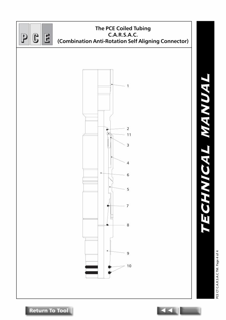
TE
CH
NIC
AL
MA
NU
AL
1
2
11
3
4
6
5
7
8
9
10
The PCE Coiled TubingC.A.R.S.A.C.
(Combination Anti-Rotation Self Aligning Connector)
PCE
CT
C.A
.R.S
.A.C
TM
. Pag
e 4
of 4

PPPRESSURE CONTROLENGINEERING
Pressure Control EngineeringHolton Road, Holton Heath Trading Estate, Poole, Dorset, BH16 6LT. United Kingdom
Tel: +44 (0)1202 631817 Fax: +44 (0)1202 631708 E-Mail: [email protected]
TE
CH
NIC
AL
MA
NU
AL
Coiled TubingGrub Screw / Dimple
Connector
PCE
CT
Gru
b Sc
rew
/Dim
ple
Con
nect
or T
M. P
age
1 of
4
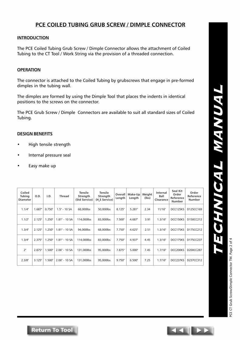
TE
CH
NIC
AL
MA
NU
AL
PCE COILED TUBING GRUB SCREW / DIMPLE CONNECTOR
INTRODUCTION
The PCE Coiled Tubing Grub Screw / Dimple Connector allows the attachment of CoiledTubing to the CT Tool / Work String via the provision of a threaded connection.
OPERATION
The connector is attached to the Coiled Tubing by grubscrews that engage in pre-formeddimples in the tubing wall.
The dimples are formed by using the Dimple Tool that places the indents in identicalpositions to the screws on the connector.
The PCE Grub Screw / Dimple Connectors are available to suit all standard sizes of CoiledTubing.
DESIGN BENEFITS
� High tensile strength
� Internal pressure seal
� Easy make up
PCE
CT
Gru
b Sc
rew
/Dim
ple
Con
nect
or T
M. P
age
2 of
4
delioCgnibuT
retemaiD.D.O .D.I daerhT
elisneThtgnertS
)ecivreSdtS(
elisneThtgnertS
H( 2 )ecivreSS
llarevOhtgneL
pU-ekaMhtgneL
thgieW)sbl(
lanretnIllaB
ecnaraelC
tiKlaeSredrO
ecnerefeRrebmuN
redrOecnerefeRrebmuN
"4/1.1 "786.1 "057.0 AS01-"5.1 sbl000,86 sbl000,05 "521.8 "182.5 43.2 "61/11 SK521CCD 961CC521D
"2/1.1 "521.2 "052.1 AS01-"18.1 sbl000,411 sbl000,38 "005.7 "786.4 19.3 "61/3.1 SK051CCD 212CC051D
"4/3.1 "521.2 "052.1 AS01-"18.1 sbl000,49 sbl000,86 "057.7 "526.4 15.2 "61/3.1 SK571CCD 212CC571D
"4/3.1 "573.2 "052.1 AS01-"18.1 sbl000,411 sbl000,38 "057.7 "739.4 54.4 "61/3.1 SK571CCD 732CC571D
"2 "578.2 "005.1 AS01-"60.2 sbl000,131 sbl000,59 "578.7 "000.5 54.7 "61/7.1 SK002CCD 782CC002D
"8/3.2 "521.3 "005.1 AS01-"60.2 sbl000,131 sbl000,59 "057.9 "005.6 52.7 "61/7.1 SK732CCD 213CC732D
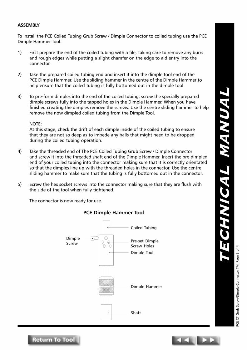
TE
CH
NIC
AL
MA
NU
AL
ASSEMBLY
To install the PCE Coiled Tubing Grub Screw / Dimple Connector to coiled tubing use the PCEDimple Hammer Tool:
1) First prepare the end of the coiled tubing with a file, taking care to remove any burrsand rough edges while putting a slight chamfer on the edge to aid entry into theconnector.
2) Take the prepared coiled tubing end and insert it into the dimple tool end of thePCE Dimple Hammer. Use the sliding hammer in the centre of the Dimple Hammer tohelp ensure that the coiled tubing is fully bottomed out in the dimple tool
3) To pre-form dimples into the end of the coiled tubing, screw the specially prepareddimple screws fully into the tapped holes in the Dimple Hammer. When you havefinished creating the dimples remove the screws. Use the centre sliding hammer to helpremove the now dimpled coiled tubing from the Dimple Tool.
NOTE:At this stage, check the drift of each dimple inside of the coiled tubing to ensurethat they are not so deep as to impede any balls that might need to be droppedduring the coiled tubing operation.
4) Take the threaded end of The PCE Coiled Tubing Grub Screw / Dimple Connectorand screw it into the threaded shaft end of the Dimple Hammer. Insert the pre-dimpledend of your coiled tubing into the connector making sure that it is correctly orientatedso that the dimples line up with the threaded holes in the connector. Use the centresliding hammer to make sure that the tubing is fully bottomed out in the connector.
5) Screw the hex socket screws into the connector making sure that they are flush withthe side of the tool when fully tightened.
The connector is now ready for use.
PCE
CT
Gru
b Sc
rew
/Dim
ple
Con
nect
or T
M. P
age
3 of
4
PCE Dimple Hammer Tool
DimpleScrew
Coiled Tubing
Pre-set DimpleScrew Holes
Dimple Tool
Dimple Hammer
Shaft

4
1
2
3
COILED TUBING
PCE COILED TUBINGGRUB SCREW / DIMPLE CONNECTOR
TE
CH
NIC
AL
MA
NU
AL
PCE
CT
Gru
b Sc
rew
/Dim
ple
Con
nect
or T
M. P
age
4 of
4

PPPRESSURE CONTROLENGINEERING
Pressure Control EngineeringHolton Road, Holton Heath Trading Estate, Poole, Dorset, BH16 6LT. United Kingdom
Tel: +44 (0)1202 631817 Fax: +44 (0)1202 631708 E-Mail: [email protected]
TE
CH
NIC
AL
MA
NU
AL
Coiled TubingRoll - On
Connector
PCE
CT
Roll
- O
n C
onne
ctor
TM
. Pag
e 1
of 3

TE
CH
NIC
AL
MA
NU
AL
The PCE Coiled Tubing Roll-On Connector
INTRODUCTION
The PCE Coiled Tubing Roll-On Connector allows the attachment of Coiled Tubing to the CT Tool / WorkString via the provision of a threaded connection.
DESIGN BENEFITS
● High tensile strength ● Internal pressure seal ● Easy make up
OPERATION
The PCE Coiled Tubing Roll-On Connectors are available to suit all standard sizes of Coiled Tubing.
The PCE Coiled Tubing Roll-On Connector attaches to the internal diameter of the coiled tubing andis held in place by crimping the coiled tubing around a connector profile with a special crimpingtool. In certain applications where a very slim bottom hole assembly is being used, and low torqueand tensile strength values are required, the Roll-On connector may be considered a better option tothe slip type or dimple connector.
ASSEMBLY
To install a PCE Roll-On Connector to coiled tubing:
1) Because the PCE Roll-On Connector fits internally into the coiled tubing it is first necessary todress the end of the coiled tubing to make sure of a smooth fit. File off any burrs and roughedges, paying particular attention to the inside edge. A PCE Internal Tubing Reamer can beused to remove any internal beads or seams inside the coiled tubing.
It is important that the inside of the tubing is as smooth as possible to prevent the sealing'o'ring on the connector being damaged during installation. A PCE Internal Honer can be usedfor final finishing inside the bore.
2) When the coiled tubing has been prepared, fit the connector into the end of the tubing untilit bottoms out on the shoulder. This should be a comfortable interference fit.
3) (The next part of the assembly is best performed with the connector firmly secured in a vice.)
Take the PCE Roll-On Connector Crimping Tool fitted with the crimping wheel and place onthe tubing above the connector profile. Slowly tighten and rotate the crimping tool until thetubing has been fully swaged into the connector profile. Repeat this procedure until thetubing has been swaged into all of the connector's profiles.
The connector is now ready for use.
PCE
CT
Roll
- O
n C
onne
ctor
TM
. Pag
e 2
of 3
delioC*gnibuT
retemaiD.D.O .D.I daerhT
elisneThtgnertS
dtS()ecivreS
elisneThtgnertS
H( 2S)ecivreS
llarevOhtgneL
pU-ekaMhtgneL
thgieW)sbl(
lanretnIllaB
ecnaraelC
redrOecnerefeRrebmuN
"4/1.1 "506.1 "005.0 AS01-"5.1 sbl000,65 sbl000,04 "005.7 "834.1 45.1 "61/7 61CC521OR
"2/1.1 "000.2 "526.0 AS01-"18.1 sbl000,06 sbl000,54 "786.8 "218.2 55.3 "61/9 02CC051OR
"4/3.1 "521.2 "739.0 AS01-"18.1 sbl000,37 sbl000,35 "578.7 "526.2 25.3 "8/7 12CC571OR
"2 "000.2 "052.1 AS01-"18.1 sbl000,57 sbl000,45 "000.8 "864.2 33.4 "61/3.1 02CC002OR
"8/3.2 "000.3 "005.1 AS01-"60.2 sbl000,08 sbl000,85 "573.8 "578.2 42.5 "61/7.1 03CC732OR
gniredronehw)ssenkcihtllaw&.d.o(snoisnemidliocyficepsesaelP*
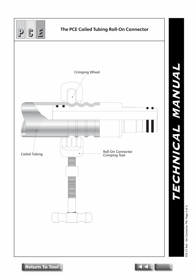
TE
CH
NIC
AL
MA
NU
ALCrimping Wheel
Coiled TubingRoll-On ConnectorCrimping Tool
The PCE Coiled Tubing Roll-On Connector
PCE
CT
Roll
- O
n C
onne
ctor
TM
. Pag
e 3
of 3

PPPRESSURE CONTROLENGINEERING
Pressure Control EngineeringHolton Road, Holton Heath Trading Estate, Poole, Dorset, BH16 6LT. United Kingdom
Tel: +44 (0)1202 631817 Fax: +44 (0)1202 631708 E-Mail: [email protected]
TE
CH
NIC
AL
MA
NU
AL
Coiled TubingGrub Screw / Dimple
Hammer
PCE
CT
Gru
b Sc
rew
/Dim
ple
Ham
mer
TM
. Pag
e 1o
f 3

TE
CH
NIC
AL
MA
NU
AL
PCE COILED TUBING GRUB SCREW / DIMPLE HAMMER
INTRODUCTION
The Dimple Hammer is used to accurately produce the indentations in the Coiled Tubing wall,required when using the Grub Screw/Dimple type Coiled Tubing connectors. (See Grub screw/Dimple Connector)
The dimples are produced by equally screwing the round headed cap screws into the tubingwall. The slide hammer aids installation and removal of the tool.
ASSEMBLY
To install the PCE Coiled Tubing Grub Screw / Dimple Connector to coiled tubing using a PCEDimple Hammer Tool:
1) First prepare the end of the coiled tubing with a file, taking care to remove any burrsand rough edges while putting a slight chamfer on the edge to aid entry into theconnector.
2) Take the prepared coiled tubing end and insert it into the dimple tool end of the PCEDimple Hammer. Use the sliding hammer in the centre of the Dimple Hammer to helpensure that the coiled tubing is fully bottomed out in the dimple tool
3) To pre-form dimples into the end of the coiled tubing, screw the specially prepareddimple screws fully into the tapped holes in the Dimple Hammer. When you havefinished creating the dimples remove the screws. Use the centre sliding hammer to helpremove the now dimpled coiled tubing from the Dimple Tool.
NOTE:At this stage check the drift of each dimple inside of the coiled tubing to ensure thatthey are not so deep as to impede any balls that might need to be dropped during thecoiled tubing operation.
4) Take the threaded end of The PCE Coiled Tubing Grub Screw / Dimple Connector andscrew it into the threaded shaft end of the Dimple Hammer. Insert the pre-dimpled endof your coiled tubing into the connector making sure that it is correctly orientated sothat the dimples line up with the threaded holes in the connector. Use the centresliding hammer to make sure that the tubing is fully bottomed out in the connector.
5) Screw the hex socket screws into the connector making sure that they are flush withthe side of the tool when fully tightened.
The connector is now ready for use.
PCE
CT
Gru
b Sc
rew
/Dim
ple
Ham
mer
TM
. Pag
e 2
of 3
gnibuTdelioCretemaiD daerhT ecnerefeRredrO
rebmuN
"4/1.1 AS01-"5.1 521TCCD
"2/1.1 AS01-"18.1 051TCCD
"4/3.1 AS01-"18.1 571TCCD
"2 AS01-"60.2 002TCCD
"8/3.2 AS01-"60.2 732TCCD

TE
CH
NIC
AL
MA
NU
AL
Dimple Screw
Coiled Tubing
Pre-set Dimple Screw Holes
Dimple Tool
Dimple Hammer
Shaft
PCE COILED TUBINGGRUB SCREW / DIMPLE HAMMER
PCE
CT
Gru
b Sc
rew
/Dim
ple
Ham
mer
TM
. Pag
e 3
of 3

PPPRESSURE CONTROLENGINEERING
Pressure Control EngineeringHolton Road, Holton Heath Trading Estate, Poole, Dorset, BH16 6LT. United Kingdom
Tel: +44 (0)1202 631817 Fax: +44 (0)1202 631708 E-Mail: [email protected]
TE
CH
NIC
AL
MA
NU
AL
Coiled TubingRoll- On Connector
CrimpingTool
PCE
CT
Roll
- O
n C
onne
ctor
Cri
mpi
ng T
ool T
M. P
age
1 of
3
TE
CH
NIC
AL
MA
NU
AL
The PCE Coiled Tubing Roll-On Connector Crimping Tool
INTRODUCTION
Used in conjunction with the PCE Coiled Tubing Roll-On Connector, the Roll-On ConnectorCrimping tool ensures easy field installation of the PCE Roll-On Connector to the coiledtubing.
The crimping tool has two interchangeable wheels, one of which is used to swage the coiledtubing onto the Roll-On Connector. The other is a cutting wheel which can be used to cutthe coiled tubing.
THE PCE COILED TUBING ROLL-ON CONNECTOR
The PCE Coiled Tubing Roll-On Connector allows the attachment of Coiled Tubing to the CTTool / Work String via the provision of a threaded connection.
The PCE Coiled Tubing Roll-On Connectors are available to suit all standard sizes of CoiledTubing.
The PCE Coiled Tubing Roll-On Connector attaches to the internal diameter of the coiledtubing and is held in place by crimping the coiled tubing around a connector profile with aspecial crimping tool. In certain applications where a very slim bottom hole assembly isbeing used, and low torque and tensile strength values are anticipated, the Roll-Onconnector may be considered a more suitable option than the slip type or dimple connector.
OPERATION INSTRUCTIONS
To install a PCE Roll-On Connector to coiled tubing using a PCE Coiled Tubing Roll-OnConnector Crimping Tool:
1) Because the PCE Roll-On Connector fits internally into the coiled tubing it is firstnecessary to dress the end of the coiled tubing to ensure of a smooth fit. File offany burrs and rough edges, paying particular attention to the insideedge. A PCEInternal Tubing Reamer can be used to remove any internal beads or seams inside thecoiled tubing.
It is important that the inside of the tubing is as smooth as possible to prevent thesealing 'o'ring on the connector being damaged during installation. A PCE InternalHoner can be used for final finishing inside the bore.
2) When the coiled tubing has been prepared, fit the connector into the end of the tubinguntil it bottoms out on the shoulder. This should be a comfortable interference fit.
3) (The next part of the assembly is best performed with the connector firmlysecured in a vice.)
Take the PCE Roll-On Connector Crimping Tool fitted with the crimping wheel and placeon the tubing above the connector profile. Slowly tighten and rotate the crimping tooluntil the tubing has been fully swaged into the connector profile. Repeat thisprocedure until the the tubing has been swaged into all of the connector's profiles.
The connector is now ready for use.
PCE
CT
Roll
- O
n C
onne
ctor
Cri
mpi
ng T
ool T
M. P
age
2 of
3

TE
CH
NIC
AL
MA
NU
ALCrimping Wheel
Coiled TubingRoll-On ConnectorCrimping Tool
The PCE Coiled TubingRoll-On Connector Crimping Tool
PCE
CT
Roll
- O
n C
onne
ctor
Cri
mpi
ng T
ool T
M. P
age
3 of
3
PPPRESSURE CONTROLENGINEERING
Pressure Control EngineeringHolton Road, Holton Heath Trading Estate, Poole, Dorset, BH16 6LT. United Kingdom
Tel: +44 (0)1202 631817 Fax: +44 (0)1202 631708 E-Mail: [email protected]
TE
CH
NIC
AL
MA
NU
AL
PCE Coiled TubingDeploymentBar System
PCE
CT
Dep
loym
ent
Bar
Syst
em T
M. P
age
1 of
5
TE
CH
NIC
AL
MA
NU
AL
PCE COILED TUBING DEPLOYMENT BAR SYSTEM
INTRODUCTION
The PCE Deployment System is designed to safely deploy coiled tubing downhole assemblies in orout of the wellbore. It uses a combination of the PCE Combination Anti-Rotation Self AligningConnector (CARSAC) and the PCE Dual Ball Kelly Cock Valve to achieve this.
The PCE CARSAC is designed to assist with the tubing �make-up� where it is difficult to rotate thetools to engage threads.
The design of the PCE CARSAC allows a high degree of torque to be transmitted through it. This isachieved by the combination of a locking taper (which permits easy stabbing) and a self aligninganti-rotation collar.
The ball valves (17) can be opened or closed at surface by the use of an Allen wrench. A Lockingfeature is incorporated in the design to hold the balls securely in the open position when run intothe wellbore.
CT Deployment Systems are available in sizes 1.11/16� through 3.1/8� o.d.
OPERATION
The tool is made up by simply stabbing the upper assembly, complete with locking collar and anti-rotation collar, into the lower female sub and screwing the locking collar down to lock the assemblytogether.
The design also allows the upper jacking collar to be used as an additional locking feature whenscrewed down on the locking collar. (As shown)
To close the ball valves simply slide the locking plate to allow a wrench to be inserted into the ballkey and rotate until the locking slot is in the horizontal position. When both balls have been closed,pressure can be bled off via the bleed screws and balls designed for that purpose. The bleed screwsare captivated by a button head screw to prevent them being backed off to far.
To open the ball valves close bleed screws and rotate ball key until the locking slot is in the verticalposition. Ensure the upper assembly connected to the dual ball valves has been assembled correctlyand pressure tested prior to opening the ball valves. Open the top ball valve first and then thebottom ball valve. Slide the locking plate through the ball key slot until both ball keys are locked inthe open position prior to running into the wellbore.
DESIGN BENEFITS
� Anti-rotation� Double �O� ring seal� Self-aligning� Easy stabbing / easy break-out� Optional or external fish necks
PCE
CT
Dep
loym
ent
Bar
Syst
em T
M. P
age
2 of
5
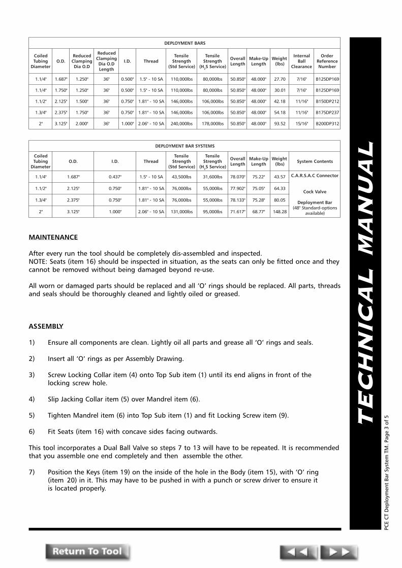
TE
CH
NIC
AL
MA
NU
AL
MAINTENANCE
After every run the tool should be completely dis-assembled and inspected.NOTE: Seats (item 16) should be inspected in situation, as the seats can only be fitted once and theycannot be removed without being damaged beyond re-use.
All worn or damaged parts should be replaced and all �O� rings should be replaced. All parts, threadsand seals should be thoroughly cleaned and lightly oiled or greased.
ASSEMBLY
1) Ensure all components are clean. Lightly oil all parts and grease all �O� rings and seals.
2) Insert all �O� rings as per Assembly Drawing.
3) Screw Locking Collar item (4) onto Top Sub item (1) until its end aligns in front of thelocking screw hole.
4) Slip Jacking Collar item (5) over Mandrel item (6).
5) Tighten Mandrel item (6) into Top Sub item (1) and fit Locking Screw item (9).
6) Fit Seats (item 16) with concave sides facing outwards.
This tool incorporates a Dual Ball Valve so steps 7 to 13 will have to be repeated. It is recommendedthat you assemble one end completely and then assemble the other.
7) Position the Keys (item 19) on the inside of the hole in the Body (item 15), with �O� ring(item 20) in it. This may have to be pushed in with a punch or screw driver to ensure itis located properly.
PCE
CT
Dep
loym
ent
Bar
Syst
em T
M. P
age
3 of
5
SRABTNEMYOLPED
delioCgnibuT
retemaiD.D.O
decudeRgnipmalC
D.OaiD
decudeRgnipmalC
D.OaiDhtgneL
.D.I daerhTelisneThtgnertS
)ecivreSdtS(
elisneThtgnertS
H( 2 )ecivreSS
llarevOhtgneL
pU-ekaMhtgneL
thgieW)sbl(
lanretnIllaB
ecnaraelC
redrOecnerefeRrebmuN
"4/1.1 "786.1 "052.1 "63 "005.0 AS01-"5.1 sbl000,011 sbl000,08 "058.05 "000.84 07.72 "61/7 961PD521B
"4/1.1 "057.1 "052.1 "63 "005.0 AS01-"5.1 sbl000,011 sbl000,08 "058.05 "000.84 10.03 "61/7 961PD521B
"2/1.1 "521.2 "005.1 "63 "057.0 AS01-"18.1 sbl000,641 sbl000,601 "058.05 "000.84 81.24 "61/11 212PD051B
"4/3.1 "573.2 "057.1 "63 "057.0 AS01-"18.1 sbl000,641 sbl000,601 "058.05 "000.84 81.45 "61/11 732PD571B
"2 "521.3 "000.2 "63 "000.1 AS01-"60.2 sbl000,042 sbl000,871 "058.05 "000.84 25.39 "61/51 213PD002B
SMETSYSRABTNEMYOLPED
delioCgnibuT
retemaiD.D.O .D.I daerhT
elisneThtgnertS
)ecivreSdtS(
elisneThtgnertS
H( 2 )ecivreSS
llarevOhtgneL
pU-ekaMhtgneL
thgieW)sbl( stnetnoCmetsyS
"4/1.1 "786.1 "734.0 AS01-"5.1 sbl005,34 sbl006,13 "070.87 "22.57 75.34 rotcennoCC.A.S.R.A.C
evlaVkcoC
raBtnemyolpeDsnoitpo-dradnatS"84(
)elbaliava
"2/1.1 "521.2 "057.0 AS01-"18.1 sbl000,67 sbl000,55 "209.77 "50.57 33.46
"4/3.1 "573.2 "057.0 AS01-"18.1 sbl000,67 sbl000,55 "331.87 "82.57 50.08
"2 "521.3 "000.1 AS01-"60.2 sbl000,131 sbl000,59 "716.17 "77.86 82.841

TE
CH
NIC
AL
MA
NU
AL
8) Turn the Key (item 19) with an Allen key so as it is in the closed position as indicated by theslots in the Body (item 15).NOTE: When the valve is open there will be one continuous slot. When closed two raised lugseither side of the hex socket on the Key (item 19) will be across the slot.
9) Position Ball (item 17) in the Body (item 15) with the keyway in the Ball (item 17) roughlyaligned with the Key (item 19).
10) Adjust the position of the Ball (item 17) until it locates fully onto the Key (item 19).
11) Press The Spring Plunger (item 21) into the slot in the Body (item 15).
12) Slide Locking Key (item 18) into the slot in the Body (item 15).
13) Make up Upper Connector Sub (item 13) and the Bottom Sub (item 22) to Body (item 15).
14) Ensure Locking Collar item (4) and Jacking Collar item (5) are backed off. Stab Mandrel item(6) into Upper Connector Sub item (13). The anti-rotation castlations should self-align, nomatter what the orientation of the two components.
15) Fit Wiper Ring item (3) by locating it on the relief diameter of the Top Sub item (1) andpushing it into the recess machined in the Collar item (4). By screwing the Collar item (4)forward slightly the Wiper Ring item (3) is retained.
16) Screw down Jacking Collar item (5) onto Upper Connector Sub item (13).
17) Screw down Locking Collar item (4) onto Jacking Collar item (5).
BLEED OFF�s
*Warning observe safety procedures when using the bleed off feature.
1) Place Ball (item 12) into tapped hole that goes through to the bore.
2) Make-up the Hex Socket Set Screw (item 10) into the same hole.
3) Make-up Button Headed Socket Set Screw (item 11) into the blind hole.
*NOTE: The Button Head of (item 11) is a safety feature in that it overlaps the hole adjacent to it toprevent screw (item 10) from being totally removed.
PCE
CT
Dep
loym
ent
Bar
Syst
em T
M. P
age
4 of
5
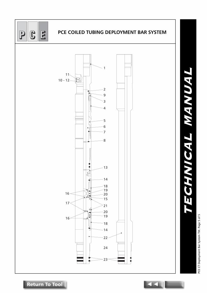
TE
CH
NIC
AL
MA
NU
AL
1
2
9
3
4
5
6
7
8
13
14
15
181920
21
2019
18
14
22
24
23
16
17
16
11
10 - 12
PCE COILED TUBING DEPLOYMENT BAR SYSTEM
PCE
CT
Dep
loym
ent
Bar
Syst
em T
M. P
age
5 of
5

PPPRESSURE CONTROLENGINEERING
Pressure Control EngineeringHolton Road, Holton Heath Trading Estate, Poole, Dorset, BH16 6LT. United Kingdom
Tel: +44 (0)1202 631817 Fax: +44 (0)1202 631708 E-Mail: [email protected]
TE
CH
NIC
AL
MA
NU
AL
Coiled TubingFlow activated
ReleasableFishing/Bulldog Spear
PCE
CT
Flow
Act
ivat
ed F
ishi
ng/B
ulld
og S
pear
TM
. Pag
e 1o
f 4

TE
CH
NIC
AL
MA
NU
AL
PCE COILED TUBING FLOW ACTIVATEDRELEASABLE FISHING/BULLDOG SPEAR
INTRODUCTION
The PCE Flow Activated Fishing/Bulldog Spear is designed to fish tools with damaged internal fishingnecks or smooth bore components lost in the well bore. The collets are interchangeable to suitdifferent size fish and range from 1.875� to 2.500� in the 2.5� tool.
The tool is latched by sitting down weight and picking up on the fish. The tool does not requireshear pins or drop balls to function. The differential pressure to release the spear is achieved bypumping through a pre-selected choke insert in the core of the tool.
PCE Flow Activated Fishing/Bulldog Spears are normally supplied with a secondary shear feature inthe event downhole conditions prevent a differential pressure situation. The lock-out ring must beremoved before running if this secondary feature is required.
The standard service tool utilises Inconel springs and is therefore trimmed for mild H2s service. FullH2s service tools are available on request.
DESIGN BENEFITS
� Flow or drop ball activated
� Hardened, double tempered slips
� Range of slips available (see table)
PCE
CT
Flow
Act
ivat
ed F
ishi
ng/B
ulld
og S
pear
TM
. Pag
e 2
of 4
delioCgnibuT
retemaiD.D.O .D.I daerhT
elisneThtgnertS
)ecivreSdtS(
elisneThtgnertS
H( 2 )ecivreSS
llarevOhtgneL
pU-ekaMhtgneL
thgieW)sbl(
lanimoNeziS
dradnatSspilS
tiKlaeSredrO
ecnerefeRrebmuN
redrOecnerefeRrebmuN
"4/1.1 "058.1 "052.0 AS01-"5.1 sbl000,14 sbl000,03 "083.81 "083.81 37.11 "2"521.1
ot"052.1
SK581AFRS 581AFRS
"2/1.1 "052.2 "093.0 AS01-"18.1 sbl000.86 sbl000,05 "026.12 "026.12 18.91 "5.2"057.1
ot"578.1
SK522AFRS 522AFRS
STESPILSRAEPSGODLLUB/GNIHSIFGNIBUTDELIOC
delioCgnibuT
retemaiD
llarevOhtgneL daerhT lanimoN
eziS ytitnauQ seziS
"4/1.1 "000.4 2-NU21-"8/1.1 "2 5 "526.1-"5.1,"5.1-"573.1,"573.1-"52.1"578.1-"57.1,"57.1-"526.1
"2/1.1 "000.6 2-NU21-"8/5.1 "5.2 5 "521.2-"2,"2-"578.1,"578.1-"57.1"573.2-"52.2,52.2-"521.2
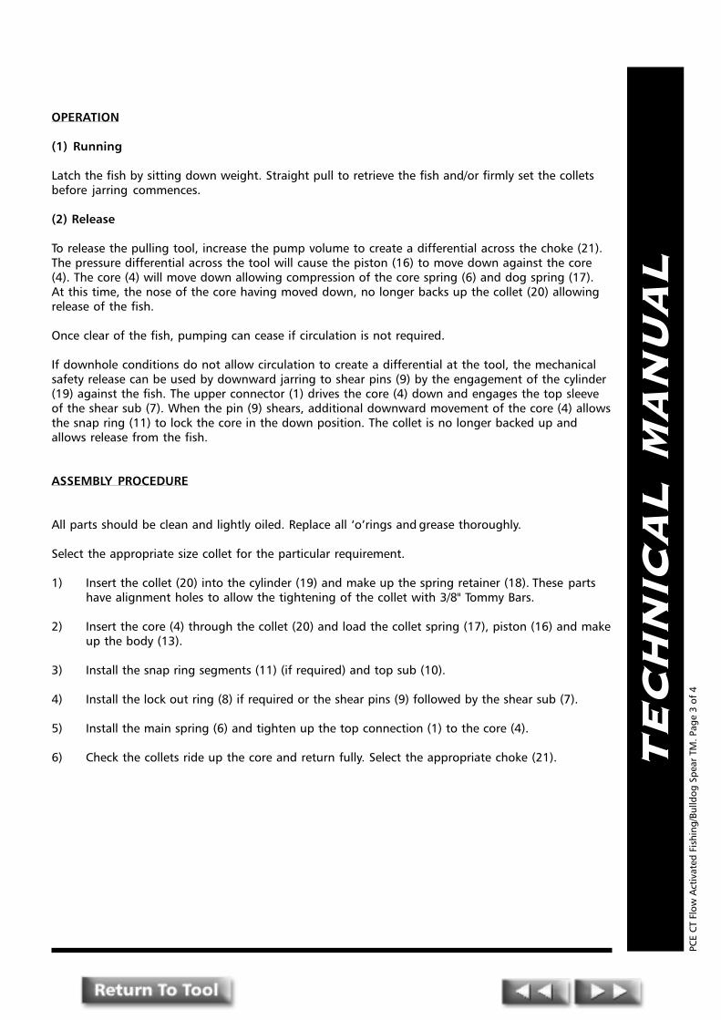
TE
CH
NIC
AL
MA
NU
AL
OPERATION
(1) Running
Latch the fish by sitting down weight. Straight pull to retrieve the fish and/or firmly set the colletsbefore jarring commences.
(2) Release
To release the pulling tool, increase the pump volume to create a differential across the choke (21).The pressure differential across the tool will cause the piston (16) to move down against the core(4). The core (4) will move down allowing compression of the core spring (6) and dog spring (17).At this time, the nose of the core having moved down, no longer backs up the collet (20) allowingrelease of the fish.
Once clear of the fish, pumping can cease if circulation is not required.
If downhole conditions do not allow circulation to create a differential at the tool, the mechanicalsafety release can be used by downward jarring to shear pins (9) by the engagement of the cylinder(19) against the fish. The upper connector (1) drives the core (4) down and engages the top sleeveof the shear sub (7). When the pin (9) shears, additional downward movement of the core (4) allowsthe snap ring (11) to lock the core in the down position. The collet is no longer backed up andallows release from the fish.
ASSEMBLY PROCEDURE
All parts should be clean and lightly oiled. Replace all �o�rings and grease thoroughly.
Select the appropriate size collet for the particular requirement.
1) Insert the collet (20) into the cylinder (19) and make up the spring retainer (18). These partshave alignment holes to allow the tightening of the collet with 3/8" Tommy Bars.
2) Insert the core (4) through the collet (20) and load the collet spring (17), piston (16) and makeup the body (13).
3) Install the snap ring segments (11) (if required) and top sub (10).
4) Install the lock out ring (8) if required or the shear pins (9) followed by the shear sub (7).
5) Install the main spring (6) and tighten up the top connection (1) to the core (4).
6) Check the collets ride up the core and return fully. Select the appropriate choke (21).
PCE
CT
Flow
Act
ivat
ed F
ishi
ng/B
ulld
og S
pear
TM
. Pag
e 3
of 4
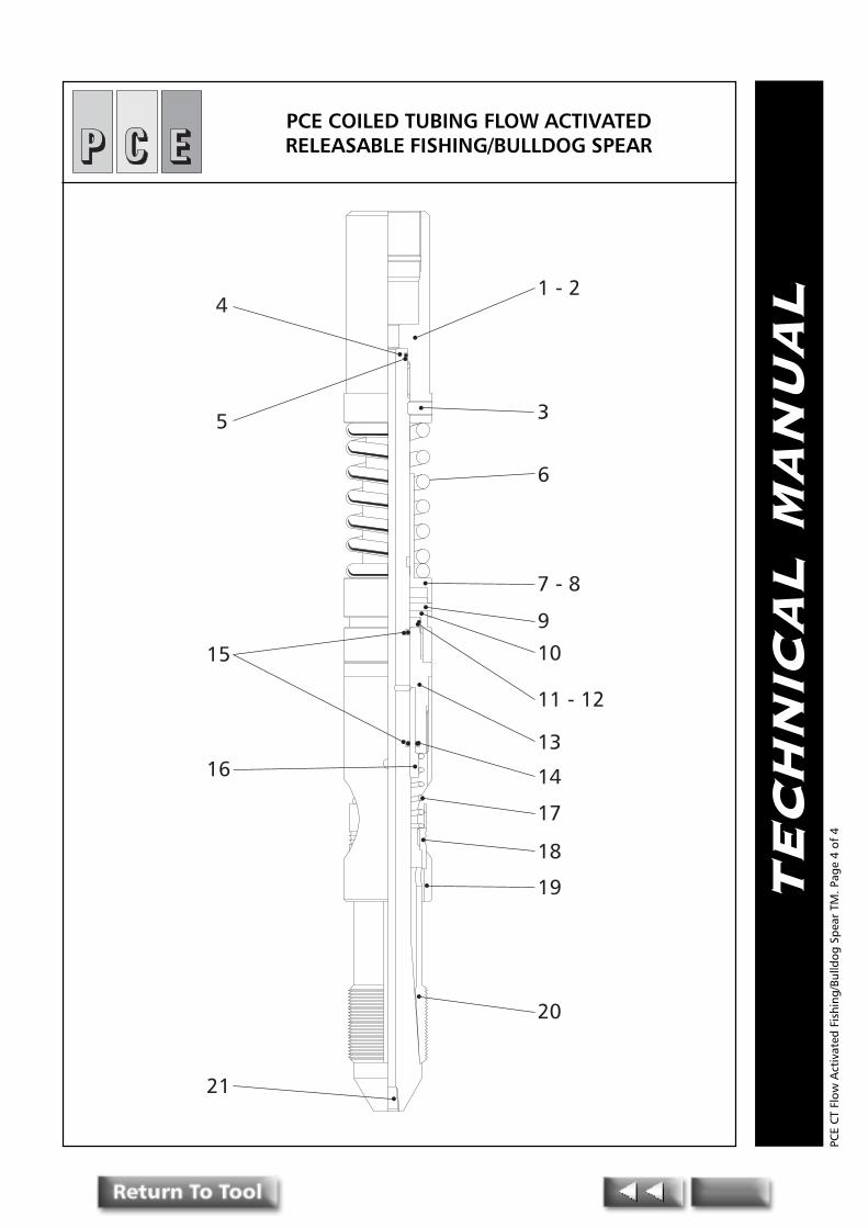
TE
CH
NIC
AL
MA
NU
AL4
5
15
16
21
1 - 2
3
6
7 - 8
9
10
11 - 12
13
14
17
18
19
20
PCE COILED TUBING FLOW ACTIVATEDRELEASABLE FISHING/BULLDOG SPEAR
PCE
CT
Flow
Act
ivat
ed F
ishi
ng/B
ulld
og S
pear
TM
. Pag
e 4
of 4

PPPRESSURE CONTROLENGINEERING
Pressure Control EngineeringHolton Road, Holton Heath Trading Estate, Poole, Dorset, BH16 6LT. United Kingdom
Tel: +44 (0)1202 631817 Fax: +44 (0)1202 631708 E-Mail: [email protected]
TE
CH
NIC
AL
MA
NU
AL
Coiled TubingFlow Activated
releasableOvershot
PCE
CT
Flow
Act
ivat
ed R
elea
sabl
e O
vers
hot
TM. P
age
1of
5
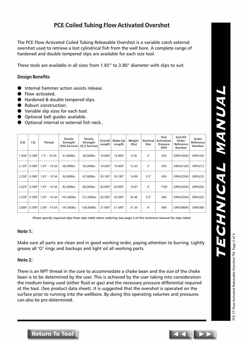
TE
CH
NIC
AL
MA
NU
AL
PCE Coiled Tubing Flow Activated Overshot
The PCE Flow Activated Coiled Tubing Releasable Overshot is a variable catch externalovershot used to retrieve a lost cylindrical fish from the well bore. A complete range ofhardened and double tempered slips are available for each size tool.
These tools are available in all sizes from 1.85� to 3.80� diameter with slips to suit.
Design Benefits
● Internal hammer action assists release.● Flow activated.● Hardened & double tempered slips.● Robust construction.● Variable slip sizes for each tool.● Optional bell guides available.● Optional internal or external fish neck..
Note 1:
Make sure all parts are clean and in good working order, paying attention to burring. Lightlygrease all �O� rings and backups and light oil all working parts.
Note 2:
There is an NPT thread in the core to accommodate a choke bean and the size of the chokebean is to be determined by the user. This is achieved by the user taking into considerationthe medium being used (either fluid or gas) and the necessary pressure differential requiredat the tool. (See product data sheet). It is suggested that the overshot is operated on thesurface prior to running into the wellbore. By doing this operating volumes and pressurescan also be pre-determined.
PCE
CT
Flow
Act
ivat
ed R
elea
sabl
e O
vers
hot
TM. P
age
2 of
5
.D.O .D.I daerhTelisneThtgnertS
)ecivreSdtS(
elisneThtgnertS
H( 2 )ecivreSS
llarevOhtgneL
pU-ekaMhtgneL
thgieW)sbl(
lanimoNeziS
looTnoitavitcA
erusserP)ISP(
tiKlaeSredrO
ecnerefeRrebmuN
redrOecnerefeRrebmuN
"058.1 "093.0 AS01-"5.1 sbl000,14 sbl000,03 "008.91 "008.91 93.9 "2 056 SK581AFRO 581AFRO
"521.2 "093.0 AS01-"18.1 sbl000,86 sbl000,05 "038.91 "038.91 36.21 "2 056 SK212AFRO 212AFRO
"052.2 "093.0 AS01-"18.1 sbl000,29 sbl000,76 "581.02 "581.02 98.41 "5.2 056 SK522AFRO 522AFRO
"526.2 "093.0 AS01-"18.1 sbl000,28 sbl000,06 "058.02 "058.02 18.91 "3 0011 SK262AFRO 262AFRO
"052.3 "093.0 AS01-"18.1 sbl000,761 sbl000,121 "005.02 "005.02 64.62 "5.3 009 SK523AFRO 523AFRO
"008.3 "093.0 AS01-"60.2 sbl000,191 sbl000,831 "540.12 "540.12 43.13 "4 009 SK083AFRO 083AFRO
)elbatspilsroflaunamlacinhcetsihtfo4egapees(gniredronehwelbatspilsmorfspilsderiuqeryficepsesaelP
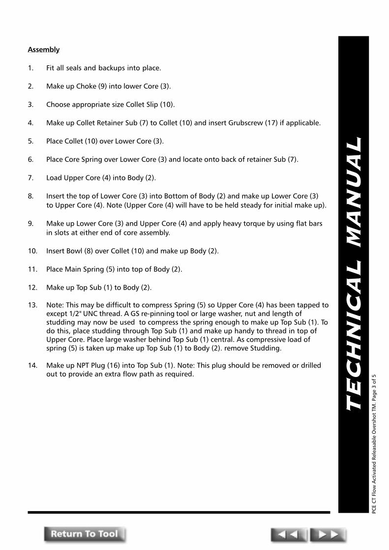
TE
CH
NIC
AL
MA
NU
AL
Assembly
1. Fit all seals and backups into place.
2. Make up Choke (9) into lower Core (3).
3. Choose appropriate size Collet Slip (10).
4. Make up Collet Retainer Sub (7) to Collet (10) and insert Grubscrew (17) if applicable.
5. Place Collet (10) over Lower Core (3).
6. Place Core Spring over Lower Core (3) and locate onto back of retainer Sub (7).
7. Load Upper Core (4) into Body (2).
8. Insert the top of Lower Core (3) into Bottom of Body (2) and make up Lower Core (3)to Upper Core (4). Note (Upper Core (4) will have to be held steady for initial make up).
9. Make up Lower Core (3) and Upper Core (4) and apply heavy torque by using flat barsin slots at either end of core assembly.
10. Insert Bowl (8) over Collet (10) and make up Body (2).
11. Place Main Spring (5) into top of Body (2).
12. Make up Top Sub (1) to Body (2).
13. Note: This may be difficult to compress Spring (5) so Upper Core (4) has been tapped toexcept 1/2" UNC thread. A GS re-pinning tool or large washer, nut and length ofstudding may now be used to compress the spring enough to make up Top Sub (1). Todo this, place studding through Top Sub (1) and make up handy to thread in top ofUpper Core. Place large washer behind Top Sub (1) central. As compressive load ofspring (5) is taken up make up Top Sub (1) to Body (2). remove Studding.
14. Make up NPT Plug (16) into Top Sub (1). Note: This plug should be removed or drilledout to provide an extra flow path as required.
PCE
CT
Flow
Act
ivat
ed R
elea
sabl
e O
vers
hot
TM. P
age
3 of
5

TE
CH
NIC
AL
MA
NU
AL
PCE Coiled Tubing Overshot Slips Table
PCE
CT
Flow
Act
ivat
ed R
elea
sabl
e O
vers
hot
TM. P
age
4 of
5
lanimoNeziS "2 "2/1-2 "3 "2/1-3 "4
lautcA.D.O "058.1 "052.2 "526.2 "052.3 "008.3
lanimoNeziSpilS
egnaRhctaCrebmuNtraP
egnaRhctaCrebmuNtraP
egnaRhctaCrebmuNtraP
egnaRhctaCrebmuNtraP
egnaRhctaCrebmuNtraP
"2/1-1 "61/9ot"61/7 "61/9ot"61/7 "61/9ot"8/3 "8/5ot"8/3
"8/5 "61/11ot"61/9 "61/11ot"61/9 "4/3ot"61/9
"4/3 "61/31ot"61/11 "61/31ot"61/11 "8/7ot"8/5
"8/7 "61/51ot"61/31 "61/51ot"61/31 "61/51ot"4/3
"1 "61/1-1ot"61/51 "61/1-1ot"61/51 "8/1-1ot"61/51 "61/1-1ot"8/7 "8/1-1ot"8/7
"8/1-1 "61/3-1ot"61/1-1 "61/3-1ot"61/1-1 "4/1-1ot"61/1-1
"4/1-1 "61/5-1ot"61/3-1 "61/5-1ot"61/3-1 "61/5-1ot"8/1-1 "8/3-1ot"8/1-1
"8/3-1 "61/7-1ot"61/5-1 "61/7-1ot"61/5-1 "2/1-1ot"61/5-1 "61/7-1ot"4/1-1
"2/1-1 "61/9-1ot"61/7-1 "61/9-1ot"61/7-1 "8/5-1ot"61/7-1 "8/5-1ot"8/3-1
"8/5-1 "61/11-1ot"61/9-1 "61/11-1ot"2/1-1
"4/3-1 "61/11-1ot"61/11-1 "8/7-1ot"61/11-1 "61/31-1ot"8/5-1 "8/7-1ot"8/5-1
"8/7-1 "2ot"61/31-1
"2 "61/1-2ot"8/7-1 "61/3-2ot"2 "8/1-2ot"8/7-1
"4/1-2 "61/5-2ot"8/1-2 "8/3-2ot"8/1-2
"2/1-2 "8/5-2ot"8/3-2
"4/3-2 "8/7-2ot"8/5-2
STESPILSELPPARG
eziSlanimoN "2 "5.2 "3 "5.3 "4
gnibuTdelioCeziS "4/1.1 "2/1.1 "4/3.1 "2 "8/3.2
htgneLllarevO "052.5 "052.5 "028.4 "000.6 "000.6
daerhT 2-NU21-"8/3.1 2-NU21-"8/5.1 2-NU21-"2 2-NU61-"61/7.2 2-NU21-"3
egnaR "2/1.1-"2/1 "4/3.1-"2/1 "2-"2/1 "2-"8/7 "4/3.2-"2/1
ytitnauQ 9 11 9 8 01
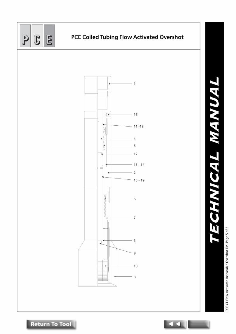
TE
CH
NIC
AL
MA
NU
AL1
16
11 -18
4
5
12
13 - 14
2
15 - 19
6
7
3
10
8
9
PCE Coiled Tubing Flow Activated Overshot
PCE
CT
Flow
Act
ivat
ed R
elea
sabl
e O
vers
hot
TM. P
age
5 of
5

PPPRESSURE CONTROLENGINEERING
Pressure Control EngineeringHolton Road, Holton Heath Trading Estate, Poole, Dorset, BH16 6LT. United Kingdom
Tel: +44 (0)1202 631817 Fax: +44 (0)1202 631708 E-Mail: [email protected]
TE
CH
NIC
AL
MA
NU
AL
Coiled TubingKnuckle
Joint
PCE
CT
Knuc
kle
Join
t TM
. Pag
e 1o
f 4
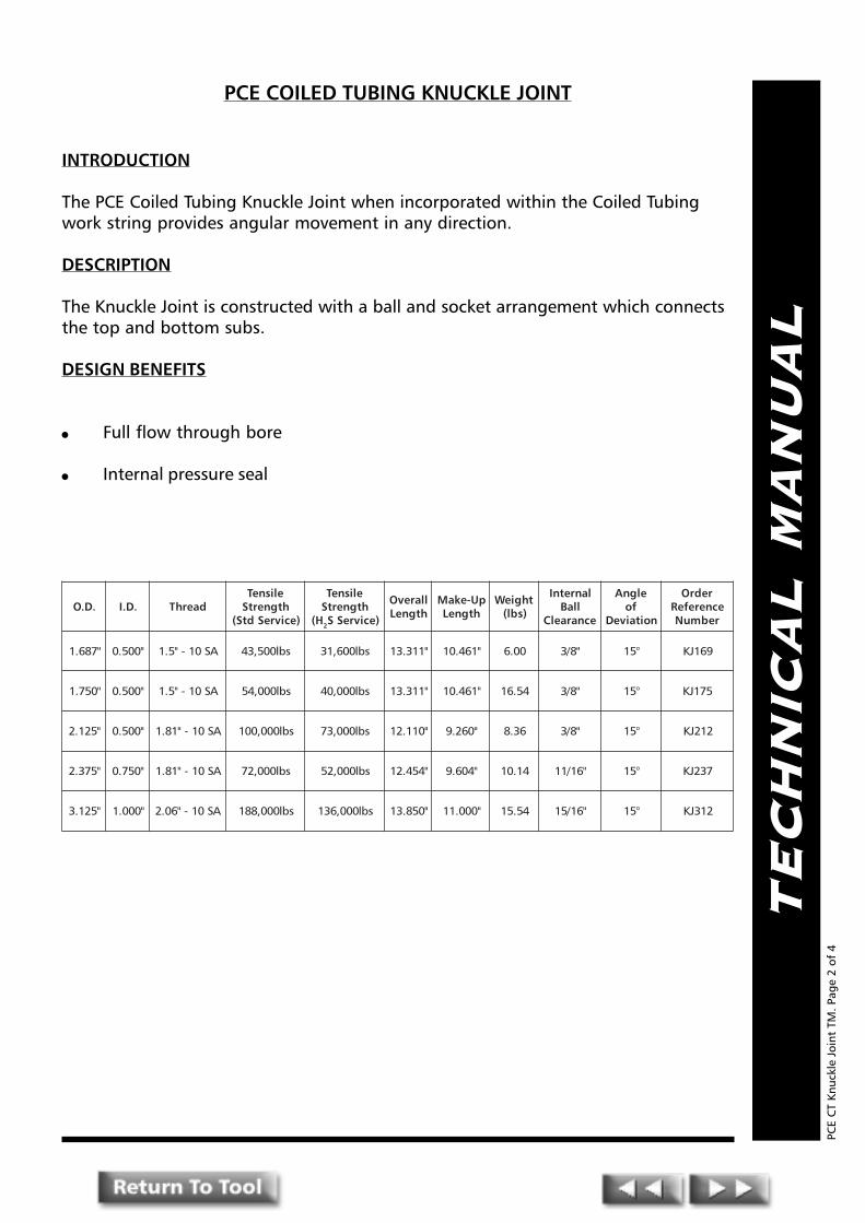
TE
CH
NIC
AL
MA
NU
AL
PCE COILED TUBING KNUCKLE JOINT
INTRODUCTION
The PCE Coiled Tubing Knuckle Joint when incorporated within the Coiled Tubingwork string provides angular movement in any direction.
DESCRIPTION
The Knuckle Joint is constructed with a ball and socket arrangement which connectsthe top and bottom subs.
DESIGN BENEFITS
l Full flow through bore
l Internal pressure seal
PCE
CT
Knuc
kle
Join
t TM
. Pag
e 2
of 4
.D.O .D.I daerhTelisneThtgnertS
)ecivreSdtS(
elisneThtgnertS
H( 2 )ecivreSS
llarevOhtgneL
pU-ekaMhtgneL
thgieW)sbl(
lanretnIllaB
ecnaraelC
elgnAfo
noitaiveD
redrOecnerefeRrebmuN
"786.1 "005.0 AS01-"5.1 sbl005,34 sbl006,13 "113.31 "164.01 00.6 "8/3 °51 961JK
"057.1 "005.0 AS01-"5.1 sbl000,45 sbl000,04 "113.31 "164.01 45.61 "8/3 °51 571JK
"521.2 "005.0 AS01-"18.1 sbl000,001 sbl000,37 "011.21 "062.9 63.8 "8/3 °51 212JK
"573.2 "057.0 AS01-"18.1 sbl000,27 sbl000,25 "454.21 "406.9 41.01 "61/11 °51 732JK
"521.3 "000.1 AS01-"60.2 sbl000,881 sbl000,631 "058.31 "000.11 45.51 "61/51 °51 213JK

TE
CH
NIC
AL
MA
NU
AL
ASSEMBLY
Install all O-rings as detailed on Assembly Drawing
1) Insert Knuckle (6) into Socket (3)
2) Make-up Bottom Sub (9) to Knuckle (6) and secure with set screw (7).
3) Make-up Top Sub (1) to Socket (3) and secure with set screw (2).
FUNCTION TEST
Function test the knuckle joint by checking that there is a full range of movementwithin the ball and socket assembly. The PCE Knuckle Joint has been designed togive long and reliable service. However, it is strongly recommended that the toolshould be disassembled and thoroughly cleaned after each use to prevent the buildup of deposits which could interfere with the operation of the tool. Thoroughcleaning is particularly important when the tool has been used in a corrosiveenvironment.
PCE
CT
Knuc
kle
Join
t TM
. Pag
e 3
of 4

TE
CH
NIC
AL
MA
NU
AL1
2
3
4
5
6
8
9
7
10
PCE COILED TUBING KNUCKLE JOINT
PCE
CT
Knuc
kle
Join
t TM
. Pag
e 4
of 4

PPPRESSURE CONTROLENGINEERING
Pressure Control EngineeringHolton Road, Holton Heath Trading Estate, Poole, Dorset, BH16 6LT. United Kingdom
Tel: +44 (0)1202 631817 Fax: +44 (0)1202 631708 E-Mail: [email protected]
TE
CH
NIC
AL
MA
NU
AL
Coiled TubingTorque - ThruKnuckle Joint
PCE
CT
Torq
ue T
hru
Knuc
kle
Join
t TM
. Pa
ge 1
of 4
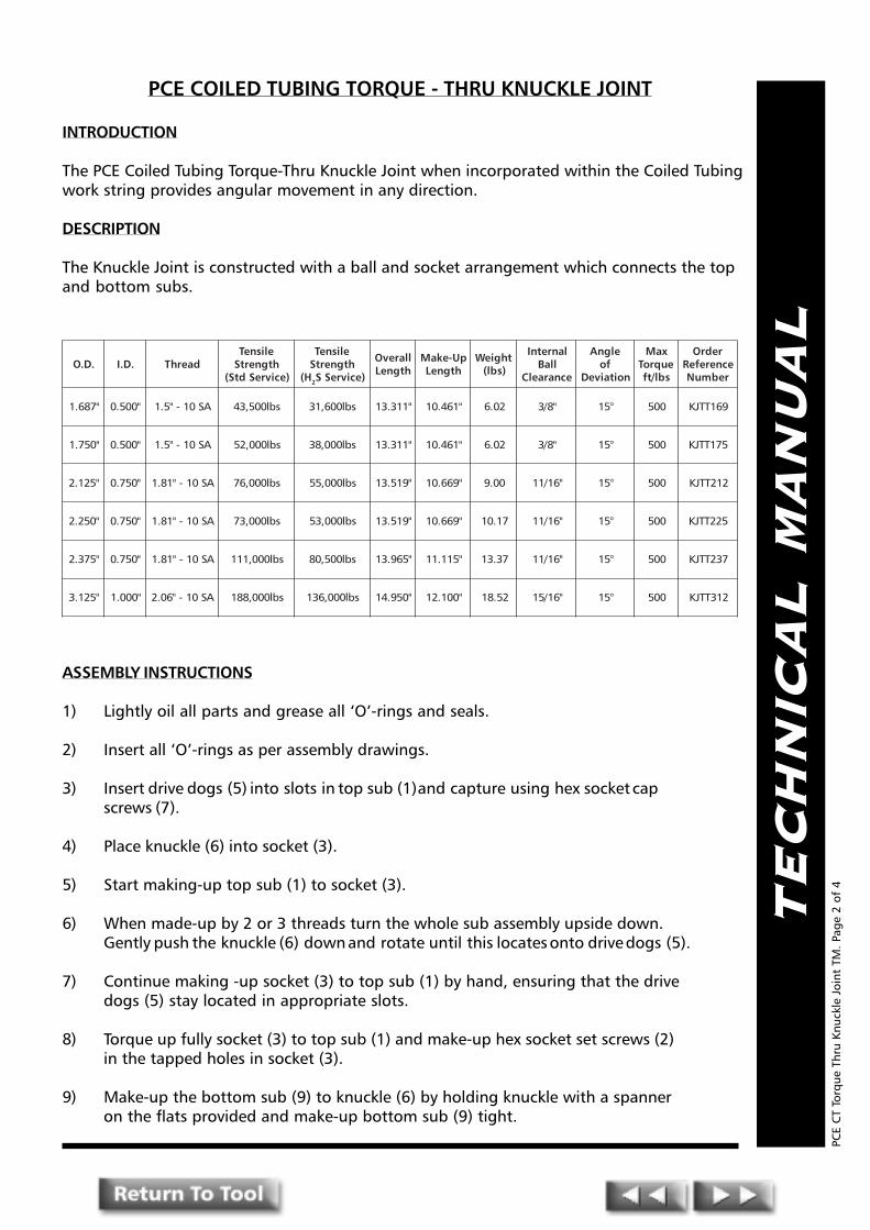
TE
CH
NIC
AL
MA
NU
AL
PCE COILED TUBING TORQUE - THRU KNUCKLE JOINT
INTRODUCTION
The PCE Coiled Tubing Torque-Thru Knuckle Joint when incorporated within the Coiled Tubingwork string provides angular movement in any direction.
DESCRIPTION
The Knuckle Joint is constructed with a ball and socket arrangement which connects the topand bottom subs.
ASSEMBLY INSTRUCTIONS
1) Lightly oil all parts and grease all �O�-rings and seals.
2) Insert all �O�-rings as per assembly drawings.
3) Insert drive dogs (5) into slots in top sub (1) and capture using hex socket capscrews (7).
4) Place knuckle (6) into socket (3).
5) Start making-up top sub (1) to socket (3).
6) When made-up by 2 or 3 threads turn the whole sub assembly upside down.Gently push the knuckle (6) down and rotate until this locates onto drive dogs (5).
7) Continue making -up socket (3) to top sub (1) by hand, ensuring that the drivedogs (5) stay located in appropriate slots.
8) Torque up fully socket (3) to top sub (1) and make-up hex socket set screws (2)in the tapped holes in socket (3).
9) Make-up the bottom sub (9) to knuckle (6) by holding knuckle with a spanneron the flats provided and make-up bottom sub (9) tight.
PCE
CT
Torq
ue T
hru
Knuc
kle
Join
t TM
. Pa
ge 2
of
4
.D.O .D.I daerhTelisneThtgnertS
)ecivreSdtS(
elisneThtgnertS
H( 2 )ecivreSS
llarevOhtgneL
pU-ekaMhtgneL
thgieW)sbl(
lanretnIllaB
ecnaraelC
elgnAfo
noitaiveD
xaMeuqroTsbl/tf
redrOecnerefeRrebmuN
"786.1 "005.0 AS01-"5.1 sbl005,34 sbl006,13 "113.31 "164.01 20.6 "8/3 °51 005 961TTJK
"057.1 "005.0 AS01-"5.1 sbl000,25 sbl000,83 "113.31 "164.01 20.6 "8/3 °51 005 571TTJK
"521.2 "057.0 AS01-"18.1 sbl000,67 sbl000,55 "915.31 "966.01 00.9 "61/11 °51 005 212TTJK
"052.2 "057.0 AS01-"18.1 sbl000,37 sbl000,35 "915.31 "966.01 71.01 "61/11 °51 005 522TTJK
"573.2 "057.0 AS01-"18.1 sbl000,111 sbl005,08 "569.31 "511.11 73.31 "61/11 °51 005 732TTJK
"521.3 "000.1 AS01-"60.2 sbl000,881 sbl000,631 "059.41 "001.21 25.81 "61/51 °51 005 213TTJK
TE
CH
NIC
AL
MA
NU
AL
10) Make-up grubscrews (8) into tapped holes in the bottom sub (9).
DIS-ASSEMBLY INSTRUCTIONS
This is the reverse of the assembly instructions
FUNCTION TEST
Function test the knuckle joint by checking that there is a full range of movement within theball and socket assembly. The Torque-Thru Knuckle Joint has been designed to give long andreliable service. However, it is strongly recommended that the tool should be disassembledand thoroughly cleaned after each use to prevent the build up of deposits which couldinterfere with the operation of the tool.
Thorough cleaning is particularly important when the tool has been used in a corrosiveenvironment.
PCE
CT
Torq
ue T
hru
Knuc
kle
Join
t TM
. Pa
ge 3
of
4

TE
CH
NIC
AL
MA
NU
AL1
2
3
11
5 -7
4
6
8
9
10
12
PCE COILED TUBINGTORQUE - THRU KNUCKLE JOINT
PCE
CT
Torq
ue T
hru
Knuc
kle
Join
t TM
. Pa
ge 4
of
4

PPPRESSURE CONTROLENGINEERING
Pressure Control EngineeringHolton Road, Holton Heath Trading Estate, Poole, Dorset, BH16 6LT. United Kingdom
Tel: +44 (0)1202 631817 Fax: +44 (0)1202 631708 E-Mail: [email protected]
TE
CH
NIC
AL
MA
NU
AL
PCE Coiled TubingSwivel Joint
PCE
CT
Swiv
el J
oint
TM
. Pag
e 1o
f 3
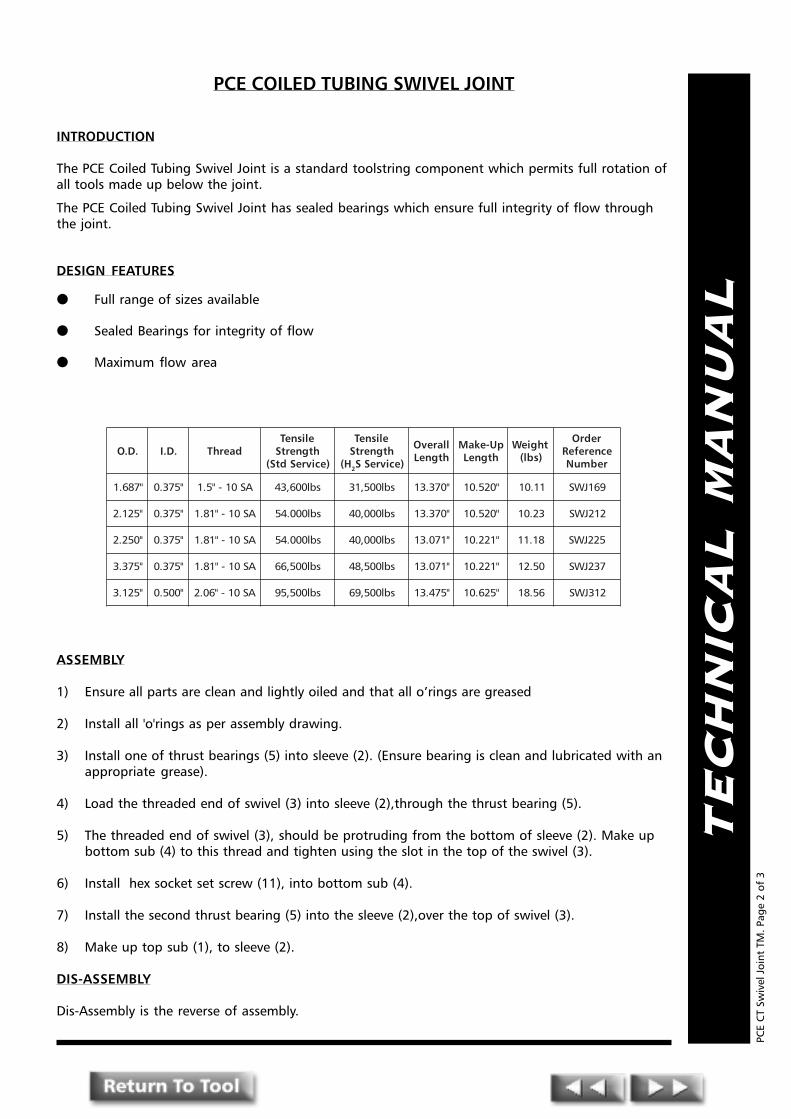
TE
CH
NIC
AL
MA
NU
AL
PCE COILED TUBING SWIVEL JOINT
INTRODUCTION
The PCE Coiled Tubing Swivel Joint is a standard toolstring component which permits full rotation ofall tools made up below the joint.
The PCE Coiled Tubing Swivel Joint has sealed bearings which ensure full integrity of flow throughthe joint.
DESIGN FEATURES
● Full range of sizes available
● Sealed Bearings for integrity of flow
● Maximum flow area
ASSEMBLY
1) Ensure all parts are clean and lightly oiled and that all o�rings are greased
2) Install all 'o'rings as per assembly drawing.
3) Install one of thrust bearings (5) into sleeve (2). (Ensure bearing is clean and lubricated with anappropriate grease).
4) Load the threaded end of swivel (3) into sleeve (2),through the thrust bearing (5).
5) The threaded end of swivel (3), should be protruding from the bottom of sleeve (2). Make upbottom sub (4) to this thread and tighten using the slot in the top of the swivel (3).
6) Install hex socket set screw (11), into bottom sub (4).
7) Install the second thrust bearing (5) into the sleeve (2),over the top of swivel (3).
8) Make up top sub (1), to sleeve (2).
DIS-ASSEMBLY
Dis-Assembly is the reverse of assembly.
PCE
CT
Swiv
el J
oint
TM
. Pag
e 2
of 3
.D.O .D.I daerhTelisneThtgnertS
)ecivreSdtS(
elisneThtgnertS
H( 2 )ecivreSS
llarevOhtgneL
pU-ekaMhtgneL
thgieW)sbl(
redrOecnerefeRrebmuN
"786.1 "573.0 AS01-"5.1 sbl006,34 sbl005,13 "073.31 "025.01 11.01 961JWS
"521.2 "573.0 AS01-"18.1 sbl000.45 sbl000,04 "073.31 "025.01 32.01 212JWS
"052.2 "573.0 AS01-"18.1 sbl000.45 sbl000,04 "170.31 "122.01 81.11 522JWS
"573.3 "573.0 AS01-"18.1 sbl005,66 sbl005,84 "170.31 "122.01 05.21 732JWS
"521.3 "005.0 AS01-"60.2 sbl005,59 sbl005,96 "574.31 "526.01 65.81 213JWS

TE
CH
NIC
AL
MA
NU
AL1
10
2
7
5
3
6
8
4
9
PCE COILED TUBING SWIVEL JOINT
PCE
CT
Swiv
el J
oint
TM
. Pag
e 3
of 3

PPPRESSURE CONTROLENGINEERING
Pressure Control EngineeringHolton Road, Holton Heath Trading Estate, Poole, Dorset, BH16 6LT. United Kingdom
Tel: +44 (0)1202 631817 Fax: +44 (0)1202 631708 E-Mail: [email protected]
TE
CH
NIC
AL
MA
NU
AL
PCE Coiled TubingJetting
Indexing Tool
PCE
CT
Jett
ing
Inde
Too
l TM
. Pag
e 1o
f 4

TE
CH
NIC
AL
MA
NU
AL
PCE COILED TUBING JETTING INDEXING TOOL
INTRODUCTION
The PCE Coiled Tubing Jetting Indexing Tool is designed for use when a controlled rotation ofthe lower tool string is required.
A typical application would be when using an angled jetting nozzle to clean the side oftubing or nipple profiles.
OPERATION
By applying a circulating pressure in access of, typically, 500psi to the PCE Indexing Tool themandrel will stroke downwards and rotate. When the circulating pressure is reduced to lessthan this pressure the internal spring moves the mandrel upwards and rotates again on a �J�profile through a pre-set angle.
This action can be repeated as often as required. The P.C.E. Coiled Tubing Indexing Tool isavailable in a number of diameters with different rotation (6 x 60°/ 10 x 36°) increments.
ASSEMBLY PROCEDURE
Prior to assembly all parts should be lightly greased or oiled
1) Install O-rings (11,12,14), back-up rings (13) and wiper ring (9) as per assemblydrawing.
2) Using a screwdriver and grease, (magnets would be helpful if available) insert camfollowers (8) into upper body (2), with the smaller end of the pin outwards.
3) Taking care insert mandrel (3) into upper body (2) carefully locating cam followers (8)into the cam track on mandrel (3).
NOTE: When making-up or breaking-out top sub (1) it is advised to grip the lower end of themandrel (3) (the area of the return spring) to prevent undue stresses being put onto camfollowers (8).
PCE
CT
Jett
ing
Inde
Too
l TM
. Pag
e 2
of 4
.D.O .D.I daerhTelisneThtgnertS
)ecivreSdtS(
elisneThtgnertS
H( 2 )ecivreSS
llarevOhtgneL
pU-ekaMhtgneL
thgieW)sbl(
lanretnIllaB
ecnaraelC
redrOecnerefeRrebmuN
"786.1 "052.0 AS01-"5.1 sbl000,13 sbl000,22 "058.13 "000.92 11.71 "61/3 961TIJ
"057.1 "052.0 AS01-"5.1 sbl000,13 sbl000,22 "058.13 "000.92 56.81 "61/3 571TIJ
"521.2 "005.0 AS01-"18.1 sbl000.38 sbl000,06 "616.62 "667.32 97.12 "61/7 212TIJ
"573.2 "005.0 AS01-"18.1 sbl000,38 sbl000,06 "053.62 "005.32 61.32 "61/7 732TIJ
"521.3 "057.0 AS01-"60.2 sbl000,201 sbl000,47 "056.22 "008.91 78.43 "61/11 213TIJ
TE
CH
NIC
AL
MA
NU
AL
4) Make-up top sub (1) to mandrel (3).
5) Slide connector sub (4) over the bottom end of the mandrel (3) and make-up to upperbody (2).
6) Slide return spring (10) over mandrel (3).
7) Slide bearing spacer (16) over the bottom end of mandrel (3) followed by bearing (15).
8) Make-up stop nut (7) to thread on bottom of mandrel (3).
9) Slide lower body (5) over return spring (10) and make-up to connector sub (4).
10) Slide bottom sub (6) over mandrel (3) and make up to lower body (5).
DISASSEMBLY PROCEDURE
This is the reverse of the assembly procedure.
After disassembly all parts should be examined for damage and cleaned beforere-assembling. O-rings should be examined and replaced as necessary.
MAINTENANCE
The Coiled Tubing Jetting Indexing Tool has been designed to give long and reliable service.However, it is strongly recommended that the tool should be disassembled and thoroughlycleaned after each use to prevent the build-up of deposits, which could interfere with theoperation of the tool. Thorough cleaning is particularly important when the tool has beenused in a corrosive environment.
PCE
CT
Jett
ing
Inde
Too
l TM
. Pag
e 3
of 4
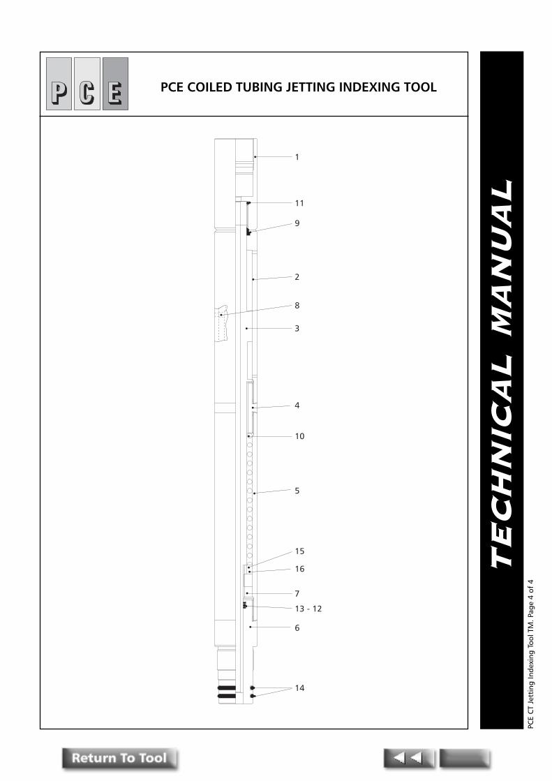
TE
CH
NIC
AL
MA
NU
AL
1
2
3
10
15
7
14
11
9
8
4
5
16
13 - 12
6
PCE COILED TUBING JETTING INDEXING TOOL
PCE
CT
Jett
ing
Inde
Too
l TM
. Pag
e 4
of 4
PPPRESSURE CONTROLENGINEERING
Pressure Control EngineeringHolton Road, Holton Heath Trading Estate, Poole, Dorset, BH16 6LT. United Kingdom
Tel: +44 (0)1202 631817 Fax: +44 (0)1202 631708 E-Mail: [email protected]
TE
CH
NIC
AL
MA
NU
AL
PCE Coiled TubingShear Release Joint
(Torque Thru)
PCE
CT
Shea
r Re
leas
e Jo
int
TM. P
age
1of
3

TE
CH
NIC
AL
MA
NU
AL
The PCE Coiled Tubing Shear Release Joint (Torque Thru)
The PCE Shear Release Joint allows the parting of the Coiled Tubing work string by appliedpre-determined tension.
The PCE Shear Release Joint was designed for and used primarily in cement stinger opera-tions as a simple effective emergency release.
The PCE Shear Release Joint incorporates shear screws that can be used in various combina-tions to allow a wide range of pre-determined shear settings.
DESIGN FEATURES
● Simple design ● On location adjustable settings
● Internal pressure seal ● Internal "GS" type fish neck after release
● Torque Thru Capability
ASSEMBLY
Make sure all parts are clean and in good working order. Lightly grease all �O� rings andbackups and lightly oil all working parts.
1) Load all �O� rings and seals
2) Insert Top Sub (1) into Bottom Sub (2)
3) Insert shear pins (5) as required and Socket Screws (4) equispaced into holes until thedesired shear value is reached.
DIS-ASSEMBLY
1) If disassembly is required Top Sub (1) and Bottom Sub (2) may be drifted apart. Lookthrough the i.d. of the tool and a clear shoulder will be visible. Using a copper or brassdrift of the approximate diameter to the shoulder, hammer sections apart and in doingso shear out shear pins.
PCE
CT
Shea
r Re
leas
e Jo
int
TM. P
age
2 of
3
lanretnIhsiF'SG'
kceNeziS
.D.O .D.I daerhTelisneThtgnertS
)ecivreSdtS(
elisneThtgnertS
H( 2 )ecivreSS
llarevOhtgneL
pU-ekaMhtgneL
thgieW)sbl(
lanretnIllaB
ecnaraelC
tiKlaeSredrO
ecnerefeRrebmuN
redrOecnerefeRrebmuN
"2 "786.1 "005.0 AS01-"5.1 sbl000,04 sbl000,92 "008.11 "059.8 43.5 "61/7 SK961TJRS 961TJRS
"2 "521.2 "057.0 AS01-"18.1 sbl000,05 sbl000,43 "005.11 "056.8 48.7 "61/11 SK212TJRS 212TJRS
"2/1.2 "573.2 "057.0 AS01-"18.1 sbl000,201 sbl000,47 "578.11 "520.9 75.01 "61/11 SK732TJRS 732TJRS
"2/1.2 "578.2 "052.1 AS01-"60.2 sbl000,011 sbl000,08 "052.21 "004.9 65.31 "8/1.1 SK782TJRS 782TJRS
"3 "521.3 "052.1 AS01-"60.2 sbl000,031 sbl000,59 "052.21 "004.9 53.61 "8/1.1 SK213TJRS 213TJRS

TE
CH
NIC
AL
MA
NU
AL
1
5
3
2
4
The PCE Coiled TubingShear Release Joint (Torque Thru)
PCE
CT
Shea
r Re
leas
e Jo
int
TM. P
age
3 of
3

PPPRESSURE CONTROLENGINEERING
Pressure Control EngineeringHolton Road, Holton Heath Trading Estate, Poole, Dorset, BH16 6LT. United Kingdom
Tel: +44 (0)1202 631817 Fax: +44 (0)1202 631708 E-Mail: [email protected]
TE
CH
NIC
AL
MA
NU
AL
Coiled TubingB.O.S.S
Release Joint
PCE
CT
B.O
.S.S
Rel
ease
Joi
nt T
M. P
age
1 of
4

TE
CH
NIC
AL
MA
NU
AL
PCE B.O.S.S Release Joint
INTRODUCTION
The PCE B.O.S.S (Hydraulic) Release Joint is designed to be made up into any coiled tubingtool-string.
Its function is to enable downhole coiled tubing disconnection at a predetermined point inthe tool-string.
The PCE B.O.S.S Release Joint comprises of an Upper Body Collet (1) which latches into aLower Body (3). Castlations machined into these two parts allow the joint to transmit torquein either direction.
The Upper Body Collet (1) is locked in position via an Inner Shear Sleeve (5). This Shear Sleeveis pinned from the o.d. of the Lower Body by a series of Shear Screws (4). These can bearranged in a number of different combinations in order to give the desired shear-outpressure for releasing the Shear Sleeve (5).
OPERATION
Prior to disconnecting using the drop ball, circulation should be established.
An Internal Drop Ball Sleeve (2) is positioned above the Shear Sleeve (5). A drop ball seats onthis sleeve so that when sufficient internal coil tubing hydraulic pressure is applied, theSleeve (2) transmits load to the Shear Sleeve (5) which shears out the Shear Screws (4) andmoves down so that the Upper Body Collet (1) is unsupported and free to disconnect fromthe Lower Body (3).
When this happens, a port will be opened above the drop ball, allowing circulation to be re-established. At this point, pumping can stop and CT pressure bled of.
The disconnected Upper Body/Collet (1) retrieves the drop ball and Drop Ball Sleeve (2).
The Lower Body (3) remains in the well and can be retrieved with a standard "GS" Type PullingTool or PCE Release Joint Retrieval Tool.
PCE
CT
B.O
.S.S
Rel
ease
Joi
nt T
M. P
age
2 of
4
.D.O .D.I daerhTelisneThtgnertS
)ecivreSdtS(
elisneThtgnertS
H( 2 )ecivreSS
llarevOhtgneL
pU-ekaMhtgneL
thgieW)sbl(
llaBesaeleR
lanretnIllaB
ecnaraelC
tiKlaeSredrO
ecnerefeRrebmuN
redrOecnerefeRrebmuN
"786.1 "005.0 AS01-"5.1 sbl000,82 sbl005,02 "006.51 "057.21 21.7 "61/9 "61/7 SK961JRBD 961JRBD
"521.2 "526.0 AS01-"18.1 sbl000,54 sbl005,23 "001.61 "052.31 55.11 "61/11 "61/9 SK212JRBD 212JRBD
"573.2 "218.0 AS01-"18.1 sbl000,26 sbl005,44 "001.61 "052.31 56.31 "8/7 "4/3 SK732JRBD 732JRBD
"521.3 "739.0 AS01-"60.2 sbl000,09 sbl000,56 "574.61 "526.31 03.52 "1 "8/7 SK213JRBD 213JRBD

TE
CH
NIC
AL
MA
NU
AL
PCE
CT
B.O
.S.S
Rel
ease
Joi
nt T
M. P
age
3 of
4
ASSEMBLY
Ensure all parts are clean and oiled. Fit all 'o'rings and lightly lubricate using MolybedenumGrease or equivelent.
1) Take Shear Sleeve (5) and push into Lower body (3), (ensure small diameter is facingdownwards). Tap the sleeve down as far as it will go.
2) Latch Upper Body/Collet (1) into the Lower Body (3), ensuring the torque drivecastlations are aligned and fully engaged.
3) From the bottom end of the Lower Body (3) drift the Shear Sleeve (5) back up tosupport the Upper Body Collet (1). the groove in the Shear Sleeve (5) will now bealigned with the shear screw holes in the Lower Body (3).
4) Fit the Shear Screws (4) as required. They should screw down flush to the body o.d.
5) Insert the Drop Ball Sleeve (2) into the Upper Body/Collet (1) until it shoulders out onthe Shear Sleeve (5).
DIS-ASSEMBLY
Assuming the Shear Screws are not sheared out:
1) Remove Shear Screws (4).
2) Drift down the Drop Ball Sleeve (2) so that the Shear Sleeve (5) is fully down and UpperBody Collet (1) is unsupported.
3) Withdraw Upper Body Collet (1).
4) Drop Ball Sleeve (2) and Shear Sleeve (5) may now be removed from their respectivebodies (1) & (3).

TE
CH
NIC
AL
MA
NU
AL
PCE B.O.S.S Release Joint
PCE
CT
B.O
.S.S
Rel
ease
Joi
nt T
M. P
age
4 of
4
1
5
4
2
3
6
10
6
9
7
8

PPPRESSURE CONTROLENGINEERING
Pressure Control EngineeringHolton Road, Holton Heath Trading Estate, Poole, Dorset, BH16 6LT. United Kingdom
Tel: +44 (0)1202 631817 Fax: +44 (0)1202 631708 E-Mail: [email protected]
TE
CH
NIC
AL
MA
NU
AL
PCE Coiled TubingFlow Activated �GS�Running/Pulling Tool
With Safety Shear
PCE
CT
Flow
Act
ivat
ed�G
S� R
unni
ng/P
ullin
g To
ol w
ith
Safe
ty S
hear
TM
. Pag
e 1o
f 7
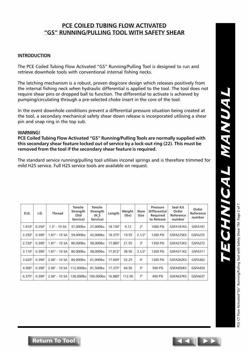
TE
CH
NIC
AL
MA
NU
AL
PCE COILED TUBING FLOW ACTIVATED�GS� RUNNING/PULLING TOOL WITH SAFETY SHEAR
INTRODUCTION
The PCE Coiled Tubing Flow Activated �GS� Running/Pulling Tool is designed to run andretrieve downhole tools with conventional internal fishing necks.
The latching mechanism is a robust, proven dog/core design which releases positively fromthe internal fishing neck when hydraulic differential is applied to the tool. The tool does notrequire shear pins or dropped ball to function. The differential to activate is achieved bypumping/circulating through a pre-selected choke insert in the core of the tool.
In the event downhole conditions prevent a differential pressure situation being created atthe tool, a secondary mechanical safety shear down release is incorporated utilising a shearpin and snap ring in the top sub.
WARNING!PCE Coiled Tubing Flow Activated �GS� Running/Pulling Tools are normally supplied withthis secondary shear feature locked out of service by a lock-out ring (22). This must beremoved from the tool if the secondary shear feature is required.
The standard service running/pulling tool utilises inconel springs and is therefore trimmed formild H2S service. Full H2S service tools are available on request.
PCE
CT
Flow
Act
ivat
ed�G
S� R
unni
ng/P
ullin
g To
ol w
ith
Safe
ty S
hear
TM
. Pag
e 2
of 7
.D.O .D.I daerhT
elisneThtgnertS
dtS()ecivreS
elisneThtgnertS
H( 2S)ecivreS
htgneL thgieW)sbl(
moNeziS
erusserPlaitnereffiD
deriuqeResaeleRot
tiKlaeSredrO
ecnerefeRrebmun
redrOecnerefeR
rebmun
"018.1 "052.0 AS01-"5.1 sbl000,73 sbl000,72 "051.81 21.9 "2 ISP0001 SK181AFSG 181AFSG
"052.2 "093.0 AS01-"18.1 sbl000,95 sbl000,34 "573.81 55.91 "2/1.2 ISP0021 SK522AFSG 522AFSG
"027.2 "093.0 AS01-"18.1 sbl000,08 sbl000,85 "588.71 55.12 "3 ISP0531 SK272AFSG 272AFSG
"011.3 "093.0 AS01-"18.1 sbl000,08 sbl000,85 "218.71 05.83 "2/1.3 ISP0021 SK113AFSG 113AFSG
"026.3 "093.0 AS01-"60.2 sbl000,48 sbl000,16 "006.71 52.25 "4 ISP0021 SK263AFSG 263AFSG
"005.4 "093.0 AS01-"60.2 sbl000,211 sbl005,18 "573.71 05.46 "5 ISP005 SK054AFSG 054AFSG
"573.6 "093.0 AS01-"60.2 sbl000,831 sbl000,001 "088.61 00.211 "7 ISP054 SK736AFSG 736AFSG

TE
CH
NIC
AL
MA
NU
AL
OPERATION
Running
When used as a running tool, simply latch the coiled tubing running tool into the internalfishing neck and run to the desired depth in the wellbore.
Fluids can be circulated down the coiled tubing and through the running tool provided thatno pressure differential of more than 200 psi created across the running tool choke (21).
NOTE:The sub surface device being run can be pushed or lightly jarred downwards into position.Heavy jarring is likely to release the safety shear should solid obstructions be reached. Thesafety release feature can be over ridden by fitting a ring below the shear sub (4) to preventdownward movement.
Once sufficient downward force or jarring has been applied, the device will be �set", upwardover pull will determine that the device is �indeed set�.
PCE
CT
Flow
Act
ivat
ed�G
S� R
unni
ng/P
ullin
g To
ol w
ith
Safe
ty S
hear
TM
. Pag
e 3
of 7
To release the running tool, increase surface pump volume to create a differential across thechoke (21). The pressure differential across the tool will cause piston (5) to move downagainst the core (15). The core (15) will move down causing compression of the core spring(8) until the upper connector (1) engages with the top of the shear sub (4). At this time thenose of the core (15) having moved down, will allow the dogs (20) to retract into the corerecess thus releasing from the fish neck.
Maintain the pump rate and pick up the tools to check release has occurred. Once clear of thefishing neck pumping can cease if circulation is not required.
Should release not occur, apply sit down weight and increase pump rate to ensure theminimum psi differential has occurred at the tool and repeat the pick-up of the tool string.
If downhole conditions do not allow circulation to create a differential at the tool, themechanical safety release can be used by downward jarring to shear pin (7) by the engage-ment of the cylinder (16) against the fishing neck. The upper connector (1) drives the core(15) down and engages the top sleeve of the shear sub (4). When the pin (7) shears, addi-tional downward movement of the core (15) allows the snap ring (6) to lock the core (15) inthe down position . The dogs (20) are no longer backed up and are retracted into the corerecess to allow release.
NOTE:The safety shear release can only function if the cylinder can engage the fish neck of the subsurface device, i.e. the core does not bottom out first. There is no requirement for the cylinderto engage the fishing neck in the normal operation.
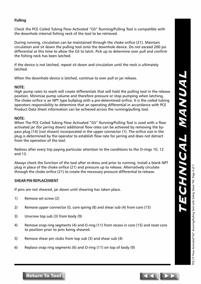
TE
CH
NIC
AL
MA
NU
AL
Pulling
Check the PCE Coiled Tubing Flow Activated �GS� Running/Pulling Tool is compatible withthe downhole internal fishing neck of the tool to be retrieved.
During running, circulation can be maintained through the choke orifice (21). Maintaincirculation and sit down the pulling tool onto the downhole device. Do not exceed 200 psidifferential at this time to allow the GS to latch. Pick up to determine over pull and confirmthe fishing neck has been latched.
If the device is not latched, repeat sit down and circulation until the neck is ultimatelylatched.
When the downhole device is latched, continue to over pull or jar release.
NOTE:High pump rates to wash will create differentials that will hold the pulling tool in the releaseposition. Minimise pump volume and therefore pressure or stop pumping when latching.The choke orifice is an NPT type bullplug with a pre-determined orifice. It is the coiled tubingoperators responsibility to determine that an operating differential in accordance with PCEProduct Data Sheet information can be achieved across the running/pulling tool.
NOTE:When The PCE Coiled Tubing Flow Activated �GS� Running/Pulling Tool is used with a flowactivated jar (for jarring down) additional flow rates can be achieved by removing the by-pass plug (14) (not shown) incorporated in the upper connector (1). The orifice size in theplug is determined by the operator to establish flow rate for jarring and does not detractfrom the operation of the tool.
Redress after every trip paying particular attention to the conditions to the O-rings 10, 12and 13.
Always check the function of the tool after re-dress and prior to running. Install a blank NPTplug in place of the choke orifice (21) and pressure up to release. Alternatively circulatethrough the choke orifice (21) to create the necessary pressure differential to release.
SHEAR PIN REPLACEMENT
If pins are not sheared, jar down until shearing has taken place.
1) Remove set screw (2)
2) Remove upper connector (l), core spring (8) and shear sub (4) from core (15)
3) Unscrew top sub (3) from body (9)
4) Remove snap ring segments (4) and O-ring (11) from recess in core (15) and reset coreto position prior to pins being sheared.
5) Remove shear pin stubs from top sub (3) and shear sub (4)
6) Replace snap ring segments (6) and O-ring (11) on top of body (9)
PCE
CT
Flow
Act
ivat
ed�G
S� R
unni
ng/P
ullin
g To
ol w
ith
Safe
ty S
hear
TM
. Pag
e 4
of 7

TE
CH
NIC
AL
MA
NU
AL
7) Screw top sub (3) onto body (9)
8) Replace shear sub (4) and pin with appropriate shear pins (7).
9) Replace core spring (8) & screw upper connector (1) on core (15) and insert set screw (2)
ASSEMBLY
All parts should be thoroughly cleaned, dried and a light coating of oil applied. Any dam-aged parts should be replaced. All o-rings should be examined for damage and replaced asrequired. All o-rings after insertion should be coated with grease. �Copper slip� should beapplied to all threads prior to make-up.
1) Assemble dogs (20) and dog retainer (19) and insert into position in the cylinder (16)
NOTE:
On the 2. l/2� Tool the dogs (20) and retainer (19) have to be positioned onto the shoulderon the bottom of the core (15). To do this pass retainer (19) down over the core (15) andplace each dog (20) into gaps in the retainer (19) allowing the bottom of the dogs (20) to siton the bottom shoulder of core (15). Hold the dogs (20) loosely so they do not drop out,pick up the dogs/core assembly and pass down through the top of the cylinder (16). Restcore (15) bottom on a bench. Lift cylinder (16) and dogs (20) should lift slightly and thensnap through and protrude from the bottom of cylinder (16).
2) Insert core (15) through dogs into cylinder (16).
3) Locate O-rings (12) onto core (15)
4) Insert the spring (18) and spring retainer (17) into cylinder from the upper end.
5) Locate O-ring (13) into body (9)
6) Locate piston (5) into body (9)
NOTE:It may be necessary to ease the piston into the body by tapping it into place as the pistonmust be pushed through the o-ring (13).
7) Screw body/piston assembly (9) & (5) into the cylinder (16)
8) Assemble snap ring segments (6) and O-ring (II) around core on top of body (9)
9) Screw top sub (3) onto body (9) encasing snap ring segments (6) and O-ring (11)
NOTE:ENSURE THE CORE DOES NOT MOVE DOWN AT THIS POINT AS THE SNAP RING SEGMENTS WILLENGAGE IN THE RECESS ON THE CORE.
10) IF SAFETY SHEAR FACILITY IS NOT REQUIRED, Place shear sub (4) and lock out ring (22)over the core (15) and insert shear pins at the required rating.
11) Place spring (8) over shear sub (4)
PCE
CT
Flow
Act
ivat
ed�G
S� R
unni
ng/P
ullin
g To
ol w
ith
Safe
ty S
hear
TM
. Pag
e 5
of 7

TE
CH
NIC
AL
MA
NU
AL
12) Position O-ring (10) onto core (15)13) Screw upper connector (1) with NPT plug (14) fitted if required, into position on core (15).
14) Insert set screw (2).
15) NOTE: (Except for 2" tool which has no choke insert)Screw choke insert (21) into core(15) .
DISASSEMBLY
To enable disassembly to take place the pins must be sheared.
Disassembly is the reverse of the assembly instructions,
MAINTENANCE
The PCE Coiled Tubing Flow Activated �GS� Running/Pulling Tool has been designed to givelong and reliable service. However, it is strongly recommended that the tool should be disas-sembled and thoroughly cleaned after each use to prevent the build-up of deposits, whichcould interfere with the operation of the tool. Thorough cleaning is particularly importantwhen the tool has been used in a corrosive environment.
PCE
CT
Flow
Act
ivat
ed�G
S� R
unni
ng/P
ullin
g To
ol w
ith
Safe
ty S
hear
TM
. Pag
e 6
of 7
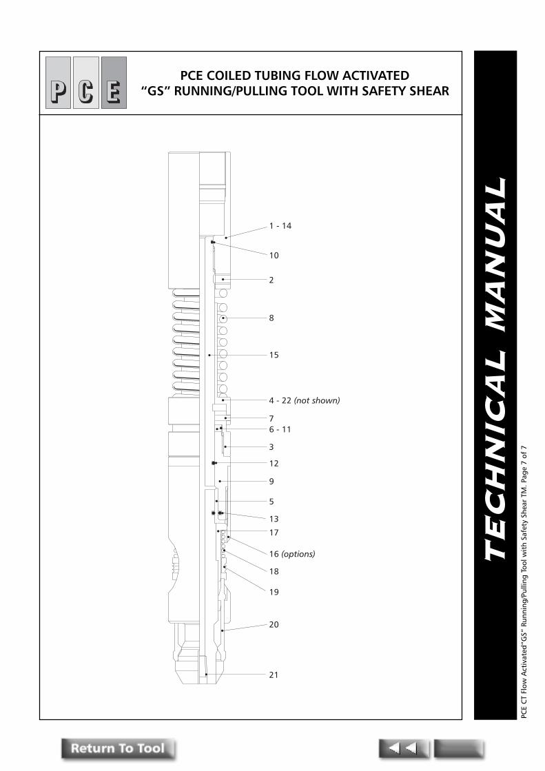
TE
CH
NIC
AL
MA
NU
AL
1 - 14
10
2
8
15
4 - 22 (not shown)
76 - 11
3
12
9
5
13
17
16 (options)
18
19
20
21
PCE COILED TUBING FLOW ACTIVATED�GS� RUNNING/PULLING TOOL WITH SAFETY SHEAR
PCE
CT
Flow
Act
ivat
ed�G
S� R
unni
ng/P
ullin
g To
ol w
ith
Safe
ty S
hear
TM
. Pag
e 7
of 7

PPPRESSURE CONTROLENGINEERING
Pressure Control EngineeringHolton Road, Holton Heath Trading Estate, Poole, Dorset, BH16 6LT. United Kingdom
Tel: +44 (0)1202 631817 Fax: +44 (0)1202 631708 E-Mail: [email protected]
TE
CH
NIC
AL
MA
NU
AL
Coiled TubingHeavy DutyReleasable
Running/Pulling Tool
PCE
CT
Hea
vy D
uty
Rele
asab
le R
unni
ng/P
ullin
g To
ol T
M. P
age
1of
5

TE
CH
NIC
AL
MA
NU
AL
PCE COILED TUBINGHEAVY DUTY RUNNING/PULLING TOOL
INTRODUCTION
The PCE Coiled Tubing Heavy Duty Running/Pulling Tool is designed to run or retrievedownhole tools that have conventional external fishing necks.
It is recommended that the PCE Heavy Duty Running/Pulling Tool is run inconjunction with a PCE Sequencing Tool.
The Heavy Duty Running/Pulling Tool is extremely robust in construction andprovides a full 360 degree dog engagement with the fishing neck when latched. ThePCE Coiled Tubing Heavy Duty Running/Pulling Tool is fully flow activated to releaseand does not require shear pins or drop ball to activate. A differential ofapproximately 700 psi at the tool will enable the tool to release.
The standard service Running/Pulling Tool utilises Inconel springs and is thereforetrimmed for mild H2S service. Full H2S service Running/Pulling Tools are available onrequest.
OPERATION
1) AS A RUNNING TOOL
When used as a running tool simply latch the Coiled Tubing Heavy Duty Running/Pulling Tool onto the external fishing neck designated as the running neck and runto the desired depth in the wellbore.
Fluid can be circulated down the coiled tubing and through the running tool atthis time provided that at no time is a pressure differential of more than 100 psicreated across the running tool choke (13) in the running tool.
PCE
CT
Hea
vy D
uty
Rele
asab
le R
unni
ng/P
ullin
g To
ol T
M. P
age
2 of
5
.D.O .D.I daerhT
elisneThtgnertS
dtS()ecivreS
elisneThtgnertS
H( 2S)ecivreS
htgneL thgieW)sbl(
moNeziS
hsiFkceNhctaC
eziS
tiKlaeSredrO
ecnerefeRrebmun
redrOecnerefeR
rebmun
"578.1 "093.0 AS01-"5.1 sbl000,08 sbl061,85 "017.61 19.8 "2 "573.1 SK781AFDH 781AFDH
"003.2 "093.0 AS01-"18.1 sbl000,09 sbl034,56 "007.61 65.41 "2/1.2 "057.1 SK032AFDH 032AFDH
"578.2 "093.0 AS01-"18.1 sbl000,341 sbl169,301 "005.61 47.12 "3 "213.2 SK782AFDH 782AFDH
"008.3 "093.0 AS01-"60.2 sbl000,891 sbl649,341 "052.61 85.43 "4 "521.3 SK083AFDH 083AFDH

TE
CH
NIC
AL
MA
NU
AL
NOTE: The PCE Sequencing Tool can be installed to control fluid circulation.A pressure differential of 5OO+psi is likely to release the tool whilst stillrunning in the wellbore.
The sub-surface device being run can be pushed or jarred downwards into positionas necessary.
Care should be exerted during this operation because downward force results in therunning tool core (10) moving upwards against springs (9) and (5) until core (l0),dog collet (11) and body (2) become one solid unit. Downward jarring when this hasoccurred will not cause any undue problems however constant downward and thenupward movement could result in damage to the dog collet (11).
Once sufficient downward force or jarring has been applied, the device will be �SET�.Applying upward over-pull on the coiled tubing will determine that the device is�INDEED SET�. Sit weight back down.
To release from running tool increase surface pump volume and therefore pressureuntil a differential greater than 700 psi is created across the choke (13). This pressurewill cause the core piston (4) to move upwards against spring (5) carrying with it thecore (10) until the core contacts the release shoulder in the dog collet (11). At thistime the dog assembly will move upwards and outwards to the release position.
Maintain the 700 psi + differential across the running tool and pick up coiled tubingweight. Retrieve running tool from the well bore. If during this operation the run-ning tool does not release from the downhole device sit down coil tubing and run-ning tool and repeat the release procedure but with increased pressure.
2) AS A PULLING TOOL
Run the correct size Coiled Tubing Heavy Duty Running Tool to the depth at whichthe downhole device to be retrieved is located. During running in, the holecirculation can be maintained through the choke orifice (13) in the pulling tool.However, a PCE Sequencing Tool is recommended for circulation. Sit down coiledtubing and pulling tool whilst circulating.
Pick-up coiled tubing weight and over-pull to determine fishing neck has beenlatched. If an increase in pick-up weight is noted continue to pull and if necessaryupward jar until device to be retrieved comes loose. Retrieve from wellbore.
If the device is not latched repeat sit down and circulation wash until neck isultimately latched. Repeat pick-up, overpulling and jarring as before.
NOTE:The choke orifice is an NPT type bull plug with a predetermined hole in it. It is theCoiled Tubing Operators responsibility to determine that an operating differential inaccordance with the PCE Product Data Sheet information can be achieved across therunning/pulling tool.
PCE
CT
Hea
vy D
uty
Rele
asab
le R
unni
ng/P
ullin
g To
ol T
M. P
age
3 of
5

TE
CH
NIC
AL
MA
NU
AL
Redress after every trip in the well bore paying particular attention to the conditionof the dog collet (11) and O-rings (6,7,8).
Always check the function of the PCE Coiled Tubing Heavy Duty Running/Pulling Toolafter redress and prior to running into the well bore. Install a blank NPT plug inplace of the choke Orifice (13) and pressurise up to release. Alternatively, circulatethrough the choke orifice (13) and create the necessary pressure differential requiredto release.
ASSEMBLY INSTRUCTIONS
All component parts, O-rings and seals to be lightly oiled prior to assembly.
1) Place O-rings (6,7,8) and back-up rings (15,16) into position.
2) Tighten choke (13) into core (10).
3) Insert core (10) through dog collet (11).
4) Place dog spring (9) over core (10).
5) Place body (2) over core (10).
6) Insert core piston (4) into body (2) and make-up core piston (4) to core (10)using a flat bladed screwdriver in the bottom of the core.
7) Make-up cylinder (12) to body (2).
8) Load core spring (5) over core piston (4).
9) Make-up top sub (1) to body (2).
(10) Tighten plug (14) into top sub (1).
DISASSEMBLY INSTRUCTIONS
The disassembly is the reverse of the assembly procedure.
PCE
CT
Hea
vy D
uty
Rele
asab
le R
unni
ng/P
ullin
g To
ol T
M. P
age
4 of
5

TE
CH
NIC
AL
MA
NU
AL
1
14
7 - 15
4
5
6
28 -16
9
10
13
11
12
PCE COILED TUBINGHEAVY DUTY RUNNING/PULLING TOOL
PCE
CT
Hea
vy D
uty
Rele
asab
le R
unni
ng/P
ullin
g To
ol T
M. P
age
5 of
5

PPPRESSURE CONTROLENGINEERING
Pressure Control EngineeringHolton Road, Holton Heath Trading Estate, Poole, Dorset, BH16 6LT. United KingdomTel: +44 (0)1202 631817 Fax: +44 (0)1202 631708 E-Mail: [email protected]
TE
CH
NIC
AL
MA
NU
AL
PCE COILED TUBINGBACK PRESSURE
VALVE
PCE
CT
Back
Pre
ssur
e Va
lve
TM. P
age
1of 3
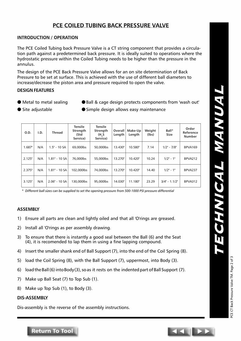
TE
CH
NIC
AL
MA
NU
AL
PCE COILED TUBING BACK PRESSURE VALVE
INTRODUCTION / OPERATION
The PCE Coiled Tubing back Pressure Valve is a CT string component that provides a circula-tion path against a predetermined back pressure. It is ideally suited to operations where thehydrostatic pressure within the Coiled Tubing needs to be higher than the pressure in theannulus.
The design of the PCE Back Pressure Valve allows for an on site determination of BackPressure to be set at surface. This is achieved with the use of different ball diameters toincrease/decrease the piston area and pressure required to open the valve.
DESIGN FEATURES
● Metal to metal sealing ● Ball & cage design protects components from 'wash out'
● Site adjustable ● Simple design allows easy maintenance
ASSEMBLY
1) Ensure all parts are clean and lightly oiled and that all 'O'rings are greased.
2) Install all 'O'rings as per assembly drawing.
3) To ensure that there is instantly a good seal between the Ball (6) and the Seat(4), it is recomended to lap them in using a fine lapping compound.
4) Insert the smaller shank end of Ball Support (7), into the end of the Coil Spring (8).
5) load the Coil Spring (8), with the Ball Support (7), uppermost, into Body (3).
6) load the Ball (6) into Body (3), so as it rests on the indented part of Ball Support (7).
7) Make up Ball Seat (7) to Top Sub (1).
8) Make up Top Sub (1), to Body (3).
DIS-ASSEMBLY
Dis-assembly is the reverse of the assembly instructions.
PCE
CT
Back
Pre
ssur
e Va
lve
TM. P
age
2 of
3
* Different ball sizes can be supplied to set the opening pressure from 500-1000 PSI pressure differential
.D.O .D.I daerhT
elisneThtgnertS
dtS()ecivreS
elisneThtgnertS
H( 2S)ecivreS
llarevOhtgneL
pU-ekaMhtgneL
thgieW)sbl(
*llaBeziS
redrOecnerefeRrebmuN
"786.1 A/N AS01-"5.1 sbl000,96 sbl000,05 "034.31 "085.01 41.7 "8/7-"2/1 961AVPB
"521.2 A/N AS01-"18.1 sbl000,67 sbl000,55 "072.31 "024.01 42.01 "1-"2/1 212AVPB
"573.2 A/N AS01-"18.1 sbl000,201 sbl000,47 "072.31 "024.01 04.41 "1-"2/1 732AVPB
"521.3 A/N AS01-"60.2 sbl000,031 sbl000,59 "030.41 "081.11 92.32 "2/1.1-"4/3 213AVPB

TE
CH
NIC
AL
MA
NU
AL
1
2
3
4
5
6
7
8
9
PCE COILED TUBING BACK PRESSURE VALVE
PCE
CT
Back
Pre
ssur
e Va
lve
TM. P
age
3 of
3
PPPRESSURE CONTROLENGINEERING
Pressure Control EngineeringHolton Road, Holton Heath Trading Estate, Poole, Dorset, BH16 6LT. United Kingdom
Tel: +44 (0)1202 631817 Fax: +44 (0)1202 631708 E-Mail: [email protected]
TE
CH
NIC
AL
MA
NU
AL
Coiled TubingDual Ball
(Kelly Cock)Valve
PCE
CT
Dua
l Bal
l Kel
ly C
ock
Valv
e TM
. Pag
e 1o
f 5
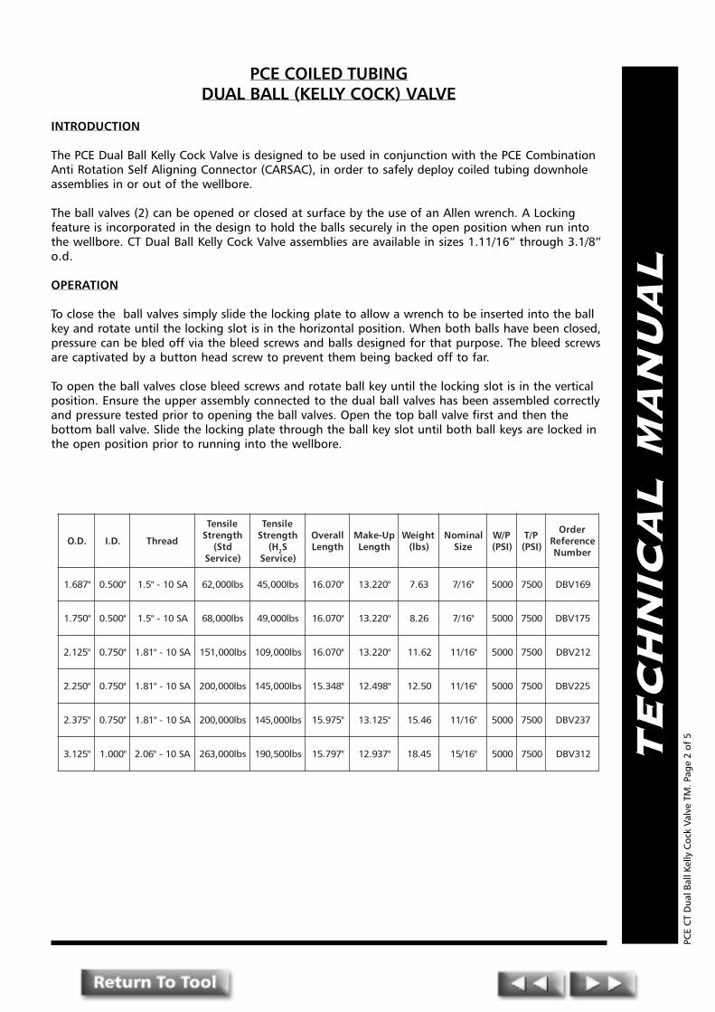
TE
CH
NIC
AL
MA
NU
AL
PCE COILED TUBINGDUAL BALL (KELLY COCK) VALVE
INTRODUCTION
The PCE Dual Ball Kelly Cock Valve is designed to be used in conjunction with the PCE CombinationAnti Rotation Self Aligning Connector (CARSAC), in order to safely deploy coiled tubing downholeassemblies in or out of the wellbore.
The ball valves (2) can be opened or closed at surface by the use of an Allen wrench. A Lockingfeature is incorporated in the design to hold the balls securely in the open position when run intothe wellbore. CT Dual Ball Kelly Cock Valve assemblies are available in sizes 1.11/16� through 3.1/8�o.d.
OPERATION
To close the ball valves simply slide the locking plate to allow a wrench to be inserted into the ballkey and rotate until the locking slot is in the horizontal position. When both balls have been closed,pressure can be bled off via the bleed screws and balls designed for that purpose. The bleed screwsare captivated by a button head screw to prevent them being backed off to far.
To open the ball valves close bleed screws and rotate ball key until the locking slot is in the verticalposition. Ensure the upper assembly connected to the dual ball valves has been assembled correctlyand pressure tested prior to opening the ball valves. Open the top ball valve first and then thebottom ball valve. Slide the locking plate through the ball key slot until both ball keys are locked inthe open position prior to running into the wellbore.
PCE
CT
Dua
l Bal
l Kel
ly C
ock
Valv
e TM
. Pag
e 2
of 5
.D.O .D.I daerhT
elisneThtgnertS
dtS()ecivreS
elisneThtgnertS
H( 2S)ecivreS
llarevOhtgneL
pU-ekaMhtgneL
thgieW)sbl(
lanimoNeziS
P/W)ISP(
P/T)ISP(
redrOecnerefeRrebmuN
"786.1 "005.0 AS01-"5.1 sbl000,26 sbl000,54 "070.61 "022.31 36.7 "61/7 0005 0057 961VBD
"057.1 "005.0 AS01-"5.1 sbl000,86 sbl000,94 "070.61 "022.31 62.8 "61/7 0005 0057 571VBD
"521.2 "057.0 AS01-"18.1 sbl000,151 sbl000,901 "070.61 "022.31 26.11 "61/11 0005 0057 212VBD
"052.2 "057.0 AS01-"18.1 sbl000,002 sbl000,541 "843.51 "894.21 05.21 "61/11 0005 0057 522VBD
"573.2 "057.0 AS01-"18.1 sbl000,002 sbl000,541 "579.51 "521.31 64.51 "61/11 0005 0057 732VBD
"521.3 "000.1 AS01-"60.2 sbl000,362 sbl005,091 "797.51 "739.21 54.81 "61/51 0005 0057 213VBD
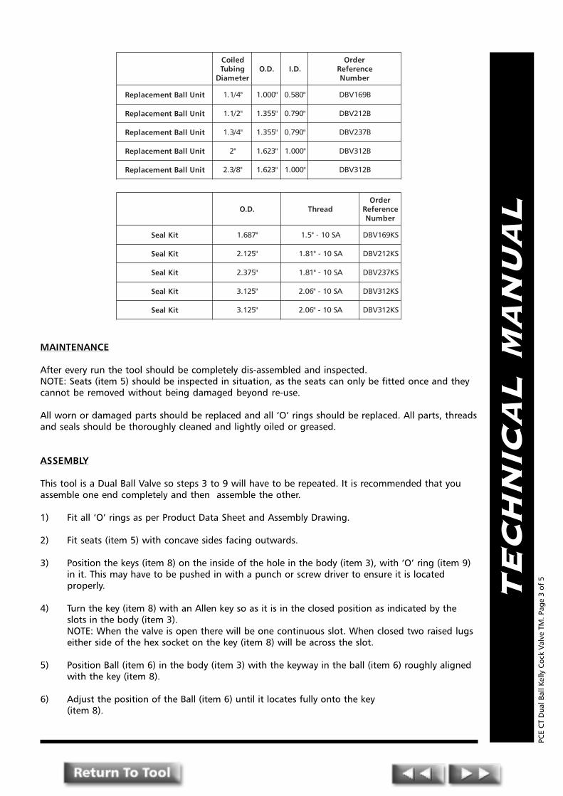
TE
CH
NIC
AL
MA
NU
AL
MAINTENANCE
After every run the tool should be completely dis-assembled and inspected.NOTE: Seats (item 5) should be inspected in situation, as the seats can only be fitted once and theycannot be removed without being damaged beyond re-use.
All worn or damaged parts should be replaced and all �O� rings should be replaced. All parts, threadsand seals should be thoroughly cleaned and lightly oiled or greased.
ASSEMBLY
This tool is a Dual Ball Valve so steps 3 to 9 will have to be repeated. It is recommended that youassemble one end completely and then assemble the other.
1) Fit all �O� rings as per Product Data Sheet and Assembly Drawing.
2) Fit seats (item 5) with concave sides facing outwards.
3) Position the keys (item 8) on the inside of the hole in the body (item 3), with �O� ring (item 9)in it. This may have to be pushed in with a punch or screw driver to ensure it is locatedproperly.
4) Turn the key (item 8) with an Allen key so as it is in the closed position as indicated by theslots in the body (item 3).NOTE: When the valve is open there will be one continuous slot. When closed two raised lugseither side of the hex socket on the key (item 8) will be across the slot.
5) Position Ball (item 6) in the body (item 3) with the keyway in the ball (item 6) roughly alignedwith the key (item 8).
6) Adjust the position of the Ball (item 6) until it locates fully onto the key(item 8).
PCE
CT
Dua
l Bal
l Kel
ly C
ock
Valv
e TM
. Pag
e 3
of 5
delioCgnibuT
retemaiD.D.O .D.I
redrOecnerefeRrebmuN
tinUllaBtnemecalpeR "4/1.1 "000.1 "085.0 B961VBD
tinUllaBtnemecalpeR "2/1.1 "553.1 "097.0 B212VBD
tinUllaBtnemecalpeR "4/3.1 "553.1 "097.0 B732VBD
tinUllaBtnemecalpeR "2 "326.1 "000.1 B213VBD
tinUllaBtnemecalpeR "8/3.2 "326.1 "000.1 B213VBD
.D.O daerhTredrO
ecnerefeRrebmuN
tiKlaeS "786.1 AS01-"5.1 SK961VBD
tiKlaeS "521.2 AS01-"18.1 SK212VBD
tiKlaeS "573.2 AS01-"18.1 SK732VBD
tiKlaeS "521.3 AS01-"60.2 SK213VBD
tiKlaeS "521.3 AS01-"60.2 SK213VBD
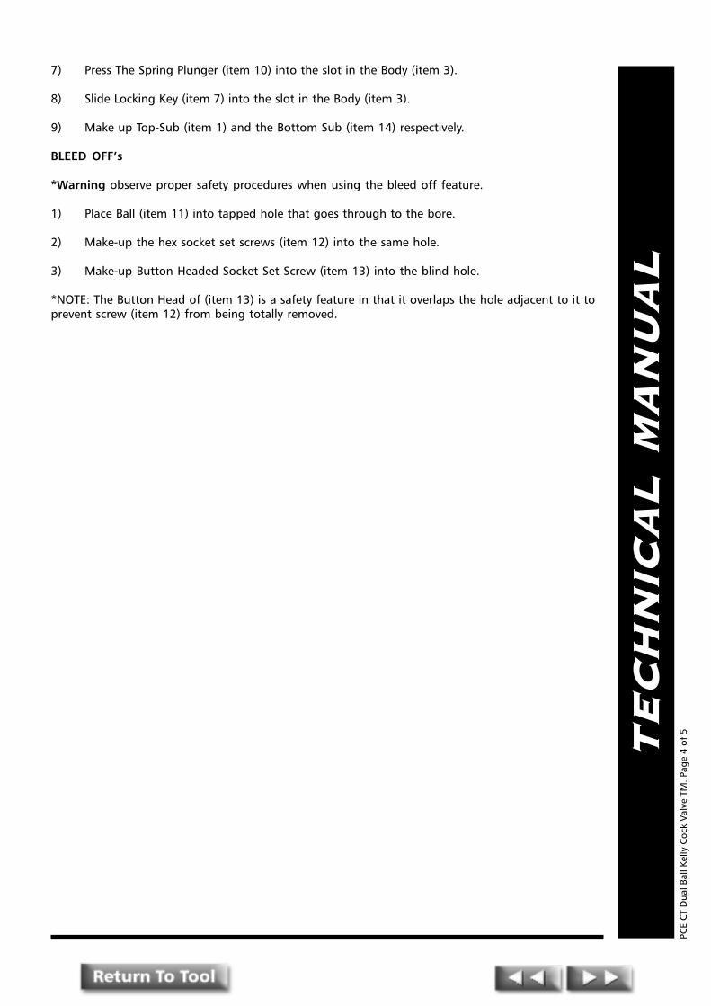
TE
CH
NIC
AL
MA
NU
AL
7) Press The Spring Plunger (item 10) into the slot in the Body (item 3).
8) Slide Locking Key (item 7) into the slot in the Body (item 3).
9) Make up Top-Sub (item 1) and the Bottom Sub (item 14) respectively.
BLEED OFF�s
*Warning observe proper safety procedures when using the bleed off feature.
1) Place Ball (item 11) into tapped hole that goes through to the bore.
2) Make-up the hex socket set screws (item 12) into the same hole.
3) Make-up Button Headed Socket Set Screw (item 13) into the blind hole.
*NOTE: The Button Head of (item 13) is a safety feature in that it overlaps the hole adjacent to it toprevent screw (item 12) from being totally removed.
PCE
CT
Dua
l Bal
l Kel
ly C
ock
Valv
e TM
. Pag
e 4
of 5

TE
CH
NIC
AL
MA
NU
AL
1
13
11 - 12
2
3
7
8
9
10
7
8
9
2
14
15
5
6
5
5
6
5
Closed
Locked Open
PCE COILED TUBINGDUAL BALL (KELLY COCK) VALVE
PCE
CT
Dua
l Bal
l Kel
ly C
ock
Valv
e TM
. Pag
e 5
of 5

PPPRESSURE CONTROLENGINEERING
Pressure Control EngineeringHolton Road, Holton Heath Trading Estate, Poole, Dorset, BH16 6LT. United Kingdom
Tel: +44 (0)1202 631817 Fax: +44 (0)1202 631708 E-Mail: [email protected]
TE
CH
NIC
AL
MA
NU
AL
Coiled TubingTwin FlapperCheck Valve
PCE
CT
Twin
Fla
pper
Che
ck V
alve
TM
. Pag
e 1o
f 4

TE
CH
NIC
AL
MA
NU
AL
PCE COILED TUBINGTWIN FLAPPER CHECK VALVE
INTRODUCTION
The P.C.E. Twin Flapper Check Valve is a standard Coiled Tubing string component. It providesa means of preventing the back flow of well fluids into the Coiled Tubing in the event offailure or damage to the Coiled Tubing string or surface equipment.
OPERATION
The design of the P.C.E. Twin Flapper Check Valve incorporates a dual sealing system in eachflapper assembly for increased safety. A moly filled teflon seat provides the primary lowpressure seal, while-at higher pressures the flappers seat on a metal-to-metal sealingarrangement.
DESIGN BENEFITS
● Dual sealing in each flapper cartridge i.e. low pressure teflon seat/seal
● High pressure full metal seat/seal
● Full bore fluid passage for balls, darts and plugs
● Removable flapper cartridges
PCE
CT
Twin
Fla
pper
Che
ck V
alve
TM
. Pag
e 2
of 4
YLBMESSAEVLAVREPPALFTNEMECALPER
.D.I .D.O stnetnoCtiK ecnerefeRredrOrebmuN
"057.0 "573.1E.F.T.PdelliFmunedbyloM%2,ssalG%32:laeS
leetSsselniatSHP4-71:reppalF&taeS,ydoB
057XlenocnI:niPegniH
961CVC
"198.0 "115.1 212CVC
"130.1 "308.1 732CVC
"573.1 "042.2 213CVC
.D.O .D.I daerhTelisneThtgnertS
)ecivreSdtS(
elisneThtgnertS
H( 2 )ecivreSS
llarevOhtgneL
pU-ekaMhtgneL
thgieW)sbl(
lanretnIllaB
ecnaraelC
tiKlaeSredrO
ecnerefeRrebmuN
redrOecnerefeRrebmuN
"786.1 "057.0 AS01-"5.1 sbl000,96 sbl000,05 "573.61 "135.31 61.8 "61/11 SK961VCFT 961VCFT
"521.2 "198.0 AS01-"18.1 sbl000,501 sbl000,08 "526.41 "057.11 00.01 "61/31 SK212VCFT 212VCFT
"573.2 "130.1 AS01-"18.1 sbl000,511 sbl000,38 "573.61 "005.31 53.31 "1 SK732VCFT 732VCFT
"521.3 "573.1 AS01-"60.2 sbl000,031 sbl000,59 "219.71 "260.51 05.42 "4/1.1 SK213VCFT 213VCFT
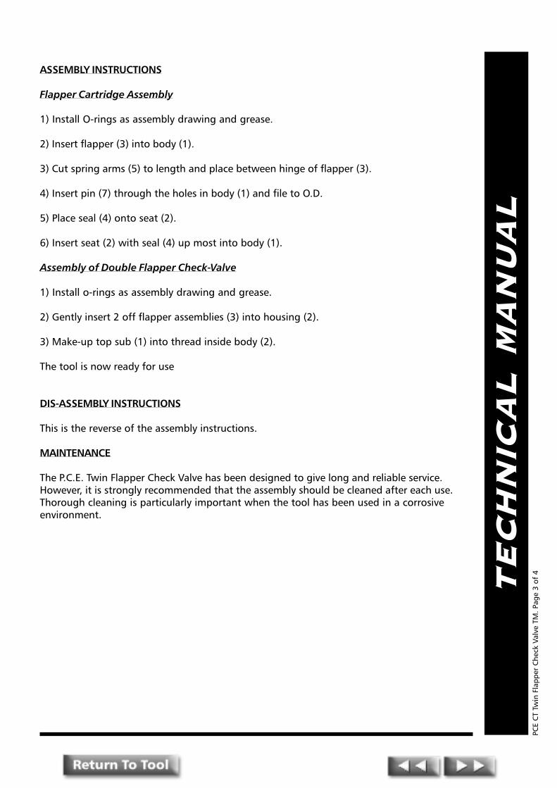
TE
CH
NIC
AL
MA
NU
AL
ASSEMBLY INSTRUCTIONS
Flapper Cartridge Assembly
1) Install O-rings as assembly drawing and grease.
2) Insert flapper (3) into body (1).
3) Cut spring arms (5) to length and place between hinge of flapper (3).
4) Insert pin (7) through the holes in body (1) and file to O.D.
5) Place seal (4) onto seat (2).
6) Insert seat (2) with seal (4) up most into body (1).
Assembly of Double Flapper Check-Valve
1) Install o-rings as assembly drawing and grease.
2) Gently insert 2 off flapper assemblies (3) into housing (2).
3) Make-up top sub (1) into thread inside body (2).
The tool is now ready for use
DIS-ASSEMBLY INSTRUCTIONS
This is the reverse of the assembly instructions.
MAINTENANCE
The P.C.E. Twin Flapper Check Valve has been designed to give long and reliable service.However, it is strongly recommended that the assembly should be cleaned after each use.Thorough cleaning is particularly important when the tool has been used in a corrosiveenvironment.
PCE
CT
Twin
Fla
pper
Che
ck V
alve
TM
. Pag
e 3
of 4
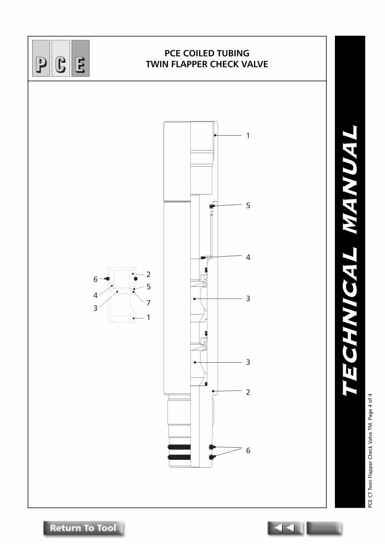
TE
CH
NIC
AL
MA
NU
AL1
5
4
3
3
2
6
6
4
3
2
1
7
5
PCE COILED TUBINGTWIN FLAPPER CHECK VALVE
PCE
CT
Twin
Fla
pper
Che
ck V
alve
TM
. Pag
e 4
of 4

PPPRESSURE CONTROLENGINEERING
Pressure Control EngineeringHolton Road, Holton Heath Trading Estate, Poole, Dorset, BH16 6LT. United Kingdom
Tel: +44 (0)1202 631817 Fax: +44 (0)1202 631708 E-Mail: [email protected]
TE
CH
NIC
AL
MA
NU
AL
Coiled TubingRotary
Wash Tool
PCE
CT
Rota
ry W
ash
Tool
TM
. Pag
e 1o
f 3
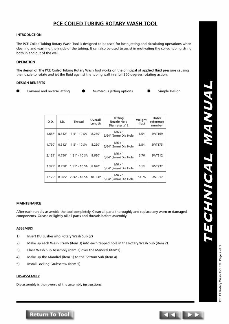
TE
CH
NIC
AL
MA
NU
AL
PCE COILED TUBING ROTARY WASH TOOL
INTRODUCTION
The PCE Coiled Tubing Rotary Wash Tool is designed to be used for both jetting and circulating operations whencleaning and washing the inside of the tubing. It can also be used to assist in motivating the coiled tubing stringboth in and out of the well.
OPERATION
The design of The PCE Coiled Tubing Rotary Wash Tool works on the principal of applied fluid pressure causingthe nozzle to rotate and jet the fluid against the tubing wall in a full 360 degrees rotating action.
DESIGN BENEFITS
●●●●● Forward and reverse jetting ●●●●● Numerous jetting options ●●●●● Simple Design
MAINTENANCE
After each run dis-assemble the tool completely. Clean all parts thoroughly and replace any worn or damagedcomponents. Grease or lightly oil all parts and threads before assembly.
ASSEMBLY
1) Insert DU Bushes into Rotary Wash Sub (2)
2) Make up each Wash Screw (item 3) into each tapped hole in the Rotary Wash Sub (item 2).
3) Place Wash Sub Assembly (item 2) over the Mandrel (item1).
4) Make up the Mandrel (item 1) to the Bottom Sub (item 4).
5) Install Locking Grubscrew (item 5).
DIS-ASSEMBLY
Dis-assembly is the reverse of the assembly instructions.
PCE
CT
Rota
ry W
ash
Tool
TM
. Pag
e 2
of 3
.D.O .D.I daerhT llarevOhtgneL
gnitteJeloHelzzoN21xretemaiD
thgieW)sbl(
redrOecnereferrebmun
"786.1 "213.0 AS01-"5.1 "052.8 1x6MeloHaiD)mm2("46/5 45.3 961TWS
"057.1 "213.0 AS01-"5.1 "052.8 1x6MeloHaiD)mm2("46/5 48.3 571TWS
"521.2 "057.0 AS01-"18.1 "026.8 1x6MeloHaiD)mm2("46/5 67.5 212TWS
"573.2 "057.0 AS01-"18.1 "026.8 1x6MeloHaiD)mm2("46/5 31.6 732TWS
"521.3 "578.0 AS01-"60.2 "083.01 1x6MeloHaiD)mm2("46/5 67.41 213TWS
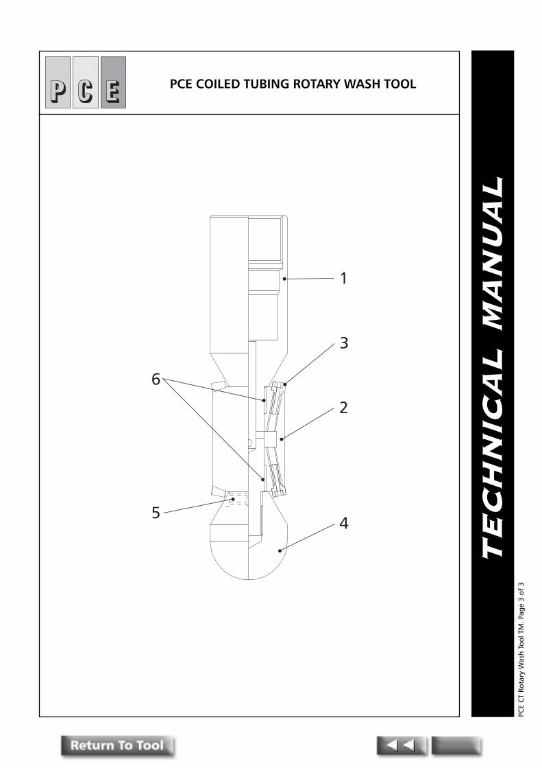
TE
CH
NIC
AL
MA
NU
AL
1
3
2
4
6
5
PCE COILED TUBING ROTARY WASH TOOL
PCE
CT
Rota
ry W
ash
Tool
TM
. Pag
e 3
of 3

PPPRESSURE CONTROLENGINEERING
Pressure Control EngineeringHolton Road, Holton Heath Trading Estate, Poole, Dorset, BH16 6LT. United Kingdom
Tel: +44 (0)1202 631817 Fax: +44 (0)1202 631708 E-Mail: [email protected]
TE
CH
NIC
AL
MA
NU
AL
Coiled TubingSequencing Tool
PCE
CT
Sequ
enci
ng T
ool T
M. P
age
1of
5

TE
CH
NIC
AL
MA
NU
AL
PCE COILED TUBING FLOW ACTIVATED SEQUENCING TOOL
INTRODUCTION
The PCE Flow Activated Sequencing Tool is designed for actuating downhole CT tools at apre-determined pressure.
The design of the PCE Flow Activated Sequencing Tool allows normal circulation, whilstrunning into the well, up to a given pump volume and therefore pressure differential at thetool. Once the design differential pressure is exceeded at the tool, the flow path is closed anddiverted into the internal bore of the toolstring, thereby enabling hydraulic activation of anytools in the lower end of the tool string. By reducing the pressure to below the designdifferential, the flow path is opened and circulation returns to the sequencing tool.
The PCE Flow Activated Sequencing Tools are available in sizes from 1-11/16" to 3-1/8"diameter.
Design Benefits
� Allows circulation whilst running into well bore
� The closing differential pressure can be field adjusted by simply placing an internal �O�ring in one of four positions, 500psi, 1000psi, 1500psi and 2000psi.
� 1/16 Upt thread in selective piston to allow insertion of even smaller orifice.
OPERATION
The Sequencing tool is designed to work by creating a pressure drop across selective pistonitem (5). The effective piston area upon which the fluid or gas created differential operates isfield adjustable by placing the piston �O� ring item (6, 7, 8, & 15) in one of the four positions.Only one �O� ring should be installed at any given time. If �O� ring item (15) is installed onthe selective piston item (5), the piston will move downward, against the resistance of thedisc springs item (10) at a flow created pressure differential of 500psi.
PCE
CT
Sequ
enci
ng T
ool T
M. P
age
2 of
5
.D.O daerhTelisneThtgnertS
)ecivreSdtS(
elisneThtgnertS
H( 2 )ecivreSS
llarevOhtgneL
pU-ekaMhtgneL
thgieW)sbl(
tiKlaeSredrO
ecnerefeRrebmuN
redrOecnerefeRrebmuN
"786.1 AS01-"5.1 sbl000,14 sbl000,03 "347.61 "398.31 81.8 SK961V4QS 961V4QS
"057.1 AS01-"5.1 sbl000,45 sbl000,93 "347.61 "398.31 24.8 SK571V4QS 571V4QS
"521.2 AS01-"18.1 sbl000,78 sbl570,36 "005.51 "056.21 51.11 SK212V4QS 212V4QS
"052.2 AS01-"18.1 sbl000,26 sbl000,54 "907.51 "958.21 08.21 SK522V4QS 522V4QS
"573.2 AS01-"18.1 sbl000,27 sbl000,25 "014.51 "065.21 81.41 SK732V4QS 732V4QS
"521.3 AS01-"60.2 sbl000,042 sbl000,571 "842.51 "893.21 72.42 SK213V4QS 213V4QS

TE
CH
NIC
AL
MA
NU
AL
Once the selective piston item (5) moves downwards, it makes a pressure seal on the ballitem (11) and the circulation flow path then diverted. All fluid or gas then flows into thelower internal bore of the tool string at the sequencing tool closing differential pressure.WARNING the sequencing tool will not close if the tubing below it is open ended. Theremust be a restriction below the sequencing tool small enough to maintain the closingdifferential pressure at the sequencing tool. If it is deemed impossible to close thesequencing tool at the lowest of the pressure settings, (500psi) because the 500psi differen-tial cannot be created at the sequencing tool due to the lack of pump volume or pressure orbecause a gas medium is being used (e.g. Nitrogen), a 1/16�npt orifice can be inserted intothe top of the thread provided at the top of the selective piston item (5). This small orficewill ultimately allow the 500psi differential to be achieved with much reduced volumes andinjection pump pressures.
IT IS THE RESPONSIBILITY OF THE INDIVIDUAL OR COMPANY RUNNING THE SEQUENCING TOOLTO ENSURE THE DOWNHOLE DIFFERENTIAL AT THE TOOL CAN BE OBTAINED IN ORDER TOGUARANTEE THE TOOLS DOWNHOLE OPERATION.
ASSEMBLY AND DISASSEMBLY
(1) Stand body (2) in the upright position and drop ball (11) into place. Install the six discsprings items (10) as per assembly drawing (three pairs of discs face to face). Ensure the discsprings and the disc spring cavity is liberally supplied with grease. Select �O� ring item (6, 7,8, or 15) and place in the respective �O� ring groove on the item (5) selective piston. The �O�ring and groove selected will determine at what pressure differential the tool will operate.Install �O� ring (1) into the groove on the piston (5). Insert the piston (5) into it�s cavity in thebody item (2). Liberally coat the top of the piston (5) with light oil. Pick up piston retaineritem (3) and install �O� ring item (4). Screw piston retainer item (3) into place in the bodyitem (2) and tighten. Install �O� ring item (13) on top and bottom subs items (1) & (2) . Installtop and bottom subs and tighten.
Disassemble in reverse order.
NOTE: After every operation in the wellbore the sequencing tool should be stripped,thoroughly cleaned and be re-assembled with new �O� rings and when necessary new balland disc springs.
TEST PROCEDURE FOR SEQUENCING TOOLS
Requirements:
1) Blank test cap to suit tool pin connection.
2) ¼� npt plug.
3) Needle Valve ¼� npt.
4) Top connection for tool with suitable entry connection.
5) Hand pump with gauge.
Procedure:
1) Check on which setting the sequencing tool is set.
PCE
CT
Sequ
enci
ng T
ool T
M. P
age
3 of
5

TE
CH
NIC
AL
MA
NU
AL
2) Assemble blank test cap on end of tool.
3) Plug (1) npt hole with plug and assemble needle valve to the other port.
4) Fit and assemble hand pump to the tool via top connection.
5) Apply pressure to the tool 200 psi in excess of set pressure.
6) Carefully open needle valve (pressure should be maintained on hand pump).
7) Reduce pressure on hand pump slowly and observe reading on gauge when pressuredrop occurs.
8) The observed pressure should coincide with the pressure selected in the tool.
PCE
CT
Sequ
enci
ng T
ool T
M. P
age
4 of
5

TE
CH
NIC
AL
MA
NU
AL
1
13
3
4
5
10
911
2
13
12
14
6, 7,8,15
PCE COILED TUBING FLOW ACTIVATEDSEQUENCING TOOL
PCE
CT
Sequ
enci
ng T
ool T
M. P
age
5 of
5

CO
ILE
D T
UB
ING
PR
OD
UC
TS
How THow THow THow THow To Conto Conto Conto Conto Contact PCEact PCEact PCEact PCEact PCE
Mail: Pressure Control EngineeringHolton RoadHolton Heath Trading EstatePooleDorsetBH16 6LTUnited Kingdom
Tel: +44 01202 631817
Fax: +44 01202 631708
E-Mail: Sales: [email protected]
Technical Support: [email protected]

Product Order Quantity Nominal Top BottomDescription Reference No. Size Connection Connection
Name: ........................................................ Position in Company: ................................................................... Date: .................
Company Name: .........................................................................................................................................................................
Operational Base / Location Address: .........................................................................................................................................
...................................................................................................................................................................................................
Zip/Post Code: ........................................... Country: ....................................................... Telephone No: ...................................
Fax No: ...................................................... E-Mail Address: .......................................................................................................
Delivery Address (if different from above) .................................................................................................................................
.................................................................................................................. Zip/Post Code: .........................................................
Country: ..................................................... Telephone No: .............................................. Fax No:..............................................
Additional / Relevent Information: .............................................................................................................................................
...................................................................................................................................................................................................
...................................................................................................................................................................................................
...................................................................................................................................................................................................
Date Delivery Required: ............................ Signature: .............................................. Print Name: ..............................................
Pressure Control EngineeringCoiled Tubing Tool
Quotation Request / Inquiry form +44 (0)1202 631708+44 (0)1202 631708+44 (0)1202 631708+44 (0)1202 631708+44 (0)1202 631708Fax