pressure independent control valves - hciterminator.com · droni coponents in 43 iller rive arren i...
TRANSCRIPT

Hydronic Components, Inc. • 7243 Miller Drive, Warren, MI 48092 • www.hciterminator.com • phone: (586) 268-1640 • fax: (586) 979-8318
Pressure Independent Control Valves

Hydronic Components, Inc. • 7243 Miller Drive, Warren, MI 48092 • www.hciterminator.com • phone: (586) 268-1640 • fax: (586) 979-8318
Pressure Independent Control ValveThe Terminator PICV Pressure Independent Control Valve is a combined constant flow limiter and full stroke, full authority, equal percentage temperature control valve.The Terminator PICV is suitable for use in variable and constant temperature systems and may be used as a con-stant flow limiter in constant volume systems (without an actuator head) or as a true PICV in variable volume systems.
Operating principles The Terminator PICV valve is made up of three main parts: 1. differential pressure regulator 2. regulating valve for flow adjustment 3. flow pre-setting knob
Differential pressure regulatorThe differential pressure regulator is the heart of the pressure independent control valve. By keeping a constant differential pressure across the control valve, constant flow and full authority temperature control can be achieved.Incoming pressure P1 is transmitted to the top face of the diaphragm, while outgoing pressure P3 is transmitted to the underside of the same diaphragm. A constant effective differential pressure is maintained between P2 and P3. As P1 increases relative to P3, it acts on the diaphragm closing the shutter (A) against a seat (B), thereby low-ering the effective differential pressure. As P1 decreases relative to P3, the diaphragm acts to open the shutter (A) from the seat (B), thus increasing the effective differential pressure. The diaphragm acts against a spring in order to balance the pressure control and stop the diaphragm oscillating.
P1 P2 P3A
1 2
3
B
Regulation valveWater flow through a valve varies as a function of the area of passage and the pressure differential across that valve. Due to the incorporation of the differential pressure regulator, the differential across the valve seats P2 – P3 is constant, meaning that flow is now only a function of area of passage.Setting and maintaining a flow rate value is also possible. The control valve presents an equal percentage characteristic.
Adjustment knobThe maximum flow can be preset, choking the outlet section of the control valve, by using the graduated adjust-ment knob. The percentage value, indicated on the scale, matches the maximum flow rate percentage. This value can be changed by turning the adjustment knob until it reaches the selected position (matching the percentage indicated on the scale). A locking mechanism stops the valve set values from being changed inadvertently.
Functional schematic
Hydronic Components, Inc. • 7243 Miller Drive, Warren, MI 48092 • www.hciterminator.com • phone: (586) 268-1640 • fax: (586) 979-8318
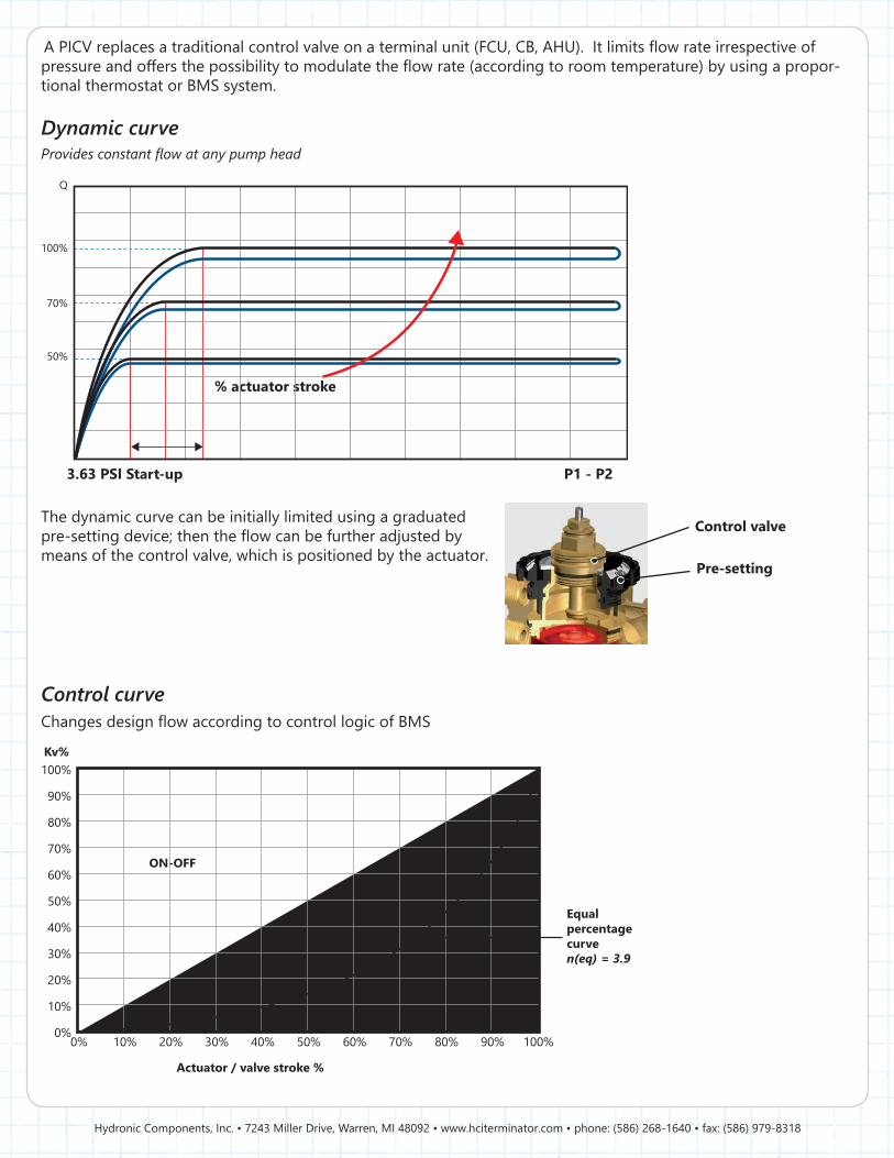
A PICV replaces a traditional control valve on a terminal unit (FCU, CB, AHU). It limits flow rate irrespective of pressure and offers the possibility to modulate the flow rate (according to room temperature) by using a propor-tional thermostat or BMS system.
Dynamic curveProvides constant flow at any pump head
3.63 PSI Start-up
% actuator stroke
P1 - P2
50%
70%
100%
Q
The dynamic curve can be initially limited using a graduated pre-setting device; then the flow can be further adjusted by means of the control valve, which is positioned by the actuator.
Control curveChanges design flow according to control logic of BMS
100%
90%
80%
70%
60%
50%
40%
30%
20%
10%
0%100%90%
Equal percentage curven(eq) = 3.9
Kv%
ON-OFF
Actuator / valve stroke %
80%70%60%50%40%30%20%10%0%
Control valve
Pre-setting

Hydronic Components, Inc. • 7243 Miller Drive, Warren, MI 48092 • www.hciterminator.com • phone: (586) 268-1640 • fax: (586) 979-8318
Actuator compatibility chart Actuator compatibility chart
93 Series3/4” thru 1”
Flexible versionAvailable with double union ends (male, female, or sweat)
Removable diaphragm for flushing, maintenance and trouble shooting
91 Series1/2” thru 3/4”
Compact versionAvailable with FIP x FIP threads
Manual flow setting device
Diapraghm is one solid piece, resulting in easier handling and maintainance.
DIAPRAGHMFlow rate can be adjusted without taking the actuator off the valve.
FLOW RATE
Thermal electricOn/OffProportional24V120V
ElectromotiveFloatingProportional24V120V
Thermal electricOn/OffProportional24V120V
ElectromotiveFloatingProportional24V120V

Hydronic Components, Inc. • 7243 Miller Drive, Warren, MI 48092 • www.hciterminator.com • phone: (586) 268-1640 • fax: (586) 979-8318
Actuator compatibility chart
85 Series1-1/4” thru 2”
90° Rotary actuator24V Proportional
90° Rotary actuator floating
24V110V
90° Rotary actuator spring return
24V110V
Manual flow setting device
Unique in the world: integrated flushing bypass modeSolid and reliable characterized control ball valveDouble union end connection for total flexibility
Control valve is fully open, con-trolling the flow through a profiled ball and a 90° rotating actuator.
OPERATION MODE
Characterized profile / full port profile
Control valve is rotated by 180°, with a profiled opening outside of the flow path. The valve now has full port passage, allowing twice the maximum flow, for proper flushing and cleaning.
FLUSHING MODE
Hydronic Components, Inc. • 7243 Miller Drive, Warren, MI 48092 • www.hciterminator.com • phone: (586) 268-1640 • fax: (586) 979-8318
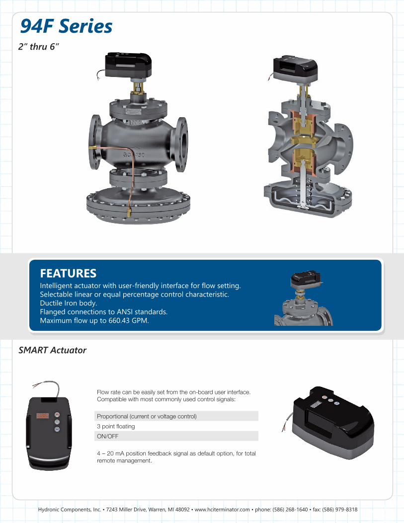
SMART Actuator
94F Series2” thru 6”
Intelligent actuator with user-friendly interface for flow setting.Selectable linear or equal percentage control characteristic.Ductile Iron body.Flanged connections to ANSI standards.Maximum flow up to 660.43 GPM.
Flow rate can be easily set from the on-board user interface.Compatible with most commonly used control signals:
Proportional (current or voltage control)
3 point floating
ON/OFF
4 – 20 mA position feedback signal as default option, for total remote management.
FEATURES
Hydronic Components, Inc. • 7243 Miller Drive, Warren, MI 48092 • www.hciterminator.com • phone: (586) 268-1640 • fax: (586) 979-8318
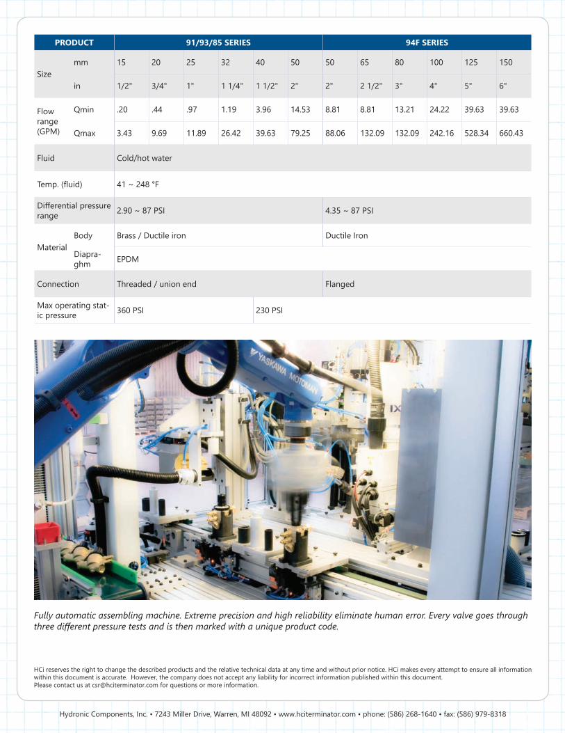
PRODUCT 91/93/85 SERIES 94F SERIES
Sizemm 15 20 25 32 40 50 50 65 80 100 125 150
in 1/2" 3/4" 1" 1 1/4" 1 1/2" 2" 2" 2 1/2" 3" 4" 5" 6"
Flow range(GPM)
Qmin .20 .44 .97 1.19 3.96 14.53 8.81 8.81 13.21 24.22 39.63 39.63
Qmax 3.43 9.69 11.89 26.42 39.63 79.25 88.06 132.09 132.09 242.16 528.34 660.43
Fluid Cold/hot water
Temp. (fluid) 41 ~ 248 °F
Differential pressure range 2.90 ~ 87 PSI 4.35 ~ 87 PSI
MaterialBody Brass / Ductile iron Ductile Iron
Diapra-ghm EPDM
Connection Threaded / union end Flanged
Max operating stat-ic pressure 360 PSI 230 PSI
Fully automatic assembling machine. Extreme precision and high reliability eliminate human error. Every valve goes through three different pressure tests and is then marked with a unique product code.
HCi reserves the right to change the described products and the relative technical data at any time and without prior notice. HCi makes every attempt to ensure all information within this document is accurate. However, the company does not accept any liability for incorrect information published within this document.Please contact us at [email protected] for questions or more information.

Hydronic Components, Inc. • 7243 Miller Drive, Warren, MI 48092 • www.hciterminator.com • phone: (586) 268-1640 • fax: (586) 979-8318
LIT-HCI-PSB
7243 Miller Drive, Warren, MI 48092www.hciterminator.comphone: (586) 268-1640fax: (586) 979-8318