pressure vessels and piping tutorial
TRANSCRIPT
EDS-2003/PV-12003 ENGINEERING DESIGN SEMINAR – LIMITED DISTRIBUTION: This material is UOP LLC technical information of a confidentialnature for use only by personnel within your organization requiring the information. The material shall not be reproduced in any manner ordistributed for any purpose whatsoever except by written permission of UOP LLC and except as authorized under agreements with UOP LLC.
Pressure Vessels
Training Services

EDS-2003/PV-22003 ENGINEERING DESIGN SEMINAR – LIMITED DISTRIBUTION: This material is UOP LLC technical information of a confidentialnature for use only by personnel within your organization requiring the information. The material shall not be reproduced in any manner ordistributed for any purpose whatsoever except by written permission of UOP LLC and except as authorized under agreements with UOP LLC.
Purpose
Introduction of the governing codes and basicconsiderations and concepts of pressure vesseldesign, fabrication, inspection, and modification.
EDS-2003/PV-32003 ENGINEERING DESIGN SEMINAR – LIMITED DISTRIBUTION: This material is UOP LLC technical information of a confidentialnature for use only by personnel within your organization requiring the information. The material shall not be reproduced in any manner ordistributed for any purpose whatsoever except by written permission of UOP LLC and except as authorized under agreements with UOP LLC.
Pressure Vessel vs Piping
n Pressure Vessel - A container in which anoccurrence takes place at a different pressurethan atmospheric
n Piping - A container used for conveyance orcontrol (valves)

EDS-2003/PV-42003 ENGINEERING DESIGN SEMINAR – LIMITED DISTRIBUTION: This material is UOP LLC technical information of a confidentialnature for use only by personnel within your organization requiring the information. The material shall not be reproduced in any manner ordistributed for any purpose whatsoever except by written permission of UOP LLC and except as authorized under agreements with UOP LLC.
EDS-2003/PV-52003 ENGINEERING DESIGN SEMINAR – LIMITED DISTRIBUTION: This material is UOP LLC technical information of a confidentialnature for use only by personnel within your organization requiring the information. The material shall not be reproduced in any manner ordistributed for any purpose whatsoever except by written permission of UOP LLC and except as authorized under agreements with UOP LLC.
Outlinen Process Engineer Responsibilitiesn Pressure Vessel Geometry and Headsn Codes and Standardsn Evaluation Methods (nondestructive
examination)n Fabrication and Weldingn Testingn Supportn Revampsn Stress and Strainn Stress Analysis and Code Rulesn Wind and Seismic Loading
EDS-2003/PV-62003 ENGINEERING DESIGN SEMINAR – LIMITED DISTRIBUTION: This material is UOP LLC technical information of a confidentialnature for use only by personnel within your organization requiring the information. The material shall not be reproduced in any manner ordistributed for any purpose whatsoever except by written permission of UOP LLC and except as authorized under agreements with UOP LLC.
n Design Pressuren Design Temperaturen Vessel Size and Orientationn Metallurgyn Nozzle Sizes and Locationn Vessel Elevationn Internal Requirements
Process/Project Engineer ResponsibilityProcess Design Conditions
EDS-2003/PV-72003 ENGINEERING DESIGN SEMINAR – LIMITED DISTRIBUTION: This material is UOP LLC technical information of a confidentialnature for use only by personnel within your organization requiring the information. The material shall not be reproduced in any manner ordistributed for any purpose whatsoever except by written permission of UOP LLC and except as authorized under agreements with UOP LLC.
Mechanical Design Features
n Vessel Thicknessn Headsn Shelln Vessel Supportn Nozzle and Manway Details
EDS-2003/PV-82003 ENGINEERING DESIGN SEMINAR – LIMITED DISTRIBUTION: This material is UOP LLC technical information of a confidentialnature for use only by personnel within your organization requiring the information. The material shall not be reproduced in any manner ordistributed for any purpose whatsoever except by written permission of UOP LLC and except as authorized under agreements with UOP LLC.
Mechanical Design Features(continued)
n Fireproofing/insulationn Internals, Including:
– Distributors– Vortex Breakers– Grids– Trays– Centerpipes and Scallops– Mesh Blankets
EDS-2003/PV-92003 ENGINEERING DESIGN SEMINAR – LIMITED DISTRIBUTION: This material is UOP LLC technical information of a confidentialnature for use only by personnel within your organization requiring the information. The material shall not be reproduced in any manner ordistributed for any purpose whatsoever except by written permission of UOP LLC and except as authorized under agreements with UOP LLC.
Process Design ConsiderationsPressure Nomenclature
n Normal Operating– Pressure at which equipment operates
n Maximum operating– Highest operating pressure foreseen for all applicable
cases (normal, turndown, startup shutdown)
n Design Pressure– Maximum operating pressure plus a safety margin
EDS-2003/PV-102003 ENGINEERING DESIGN SEMINAR – LIMITED DISTRIBUTION: This material is UOP LLC technical information of a confidentialnature for use only by personnel within your organization requiring the information. The material shall not be reproduced in any manner ordistributed for any purpose whatsoever except by written permission of UOP LLC and except as authorized under agreements with UOP LLC.
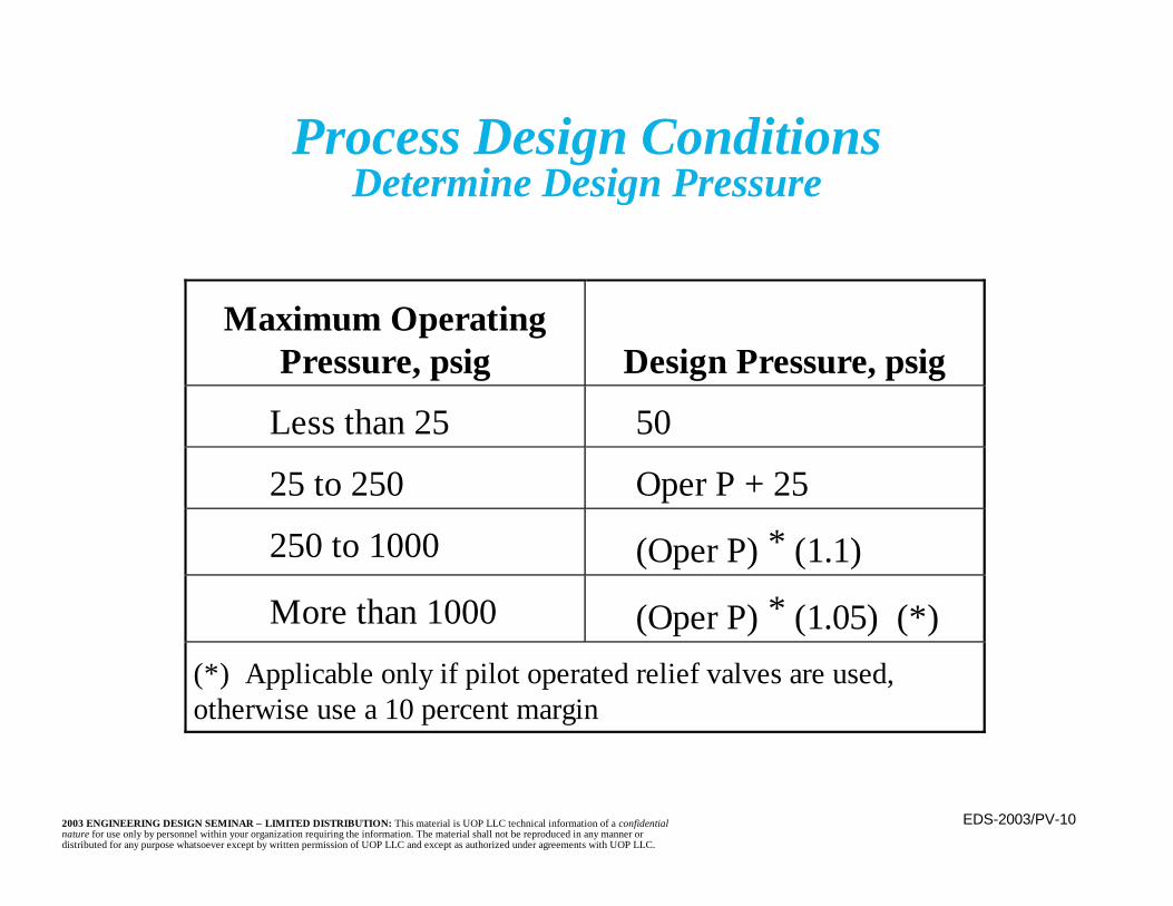
Process Design ConditionsDetermine Design Pressure
Maximum OperatingPressure, psig Design Pressure, psig
Less than 25 50
25 to 250 Oper P + 25
250 to 1000 (Oper P) ∗ (1.1)
More than 1000 (Oper P) ∗ (1.05) (*)(*) Applicable only if pilot operated relief valves are used,otherwise use a 10 percent margin

EDS-2003/PV-112003 ENGINEERING DESIGN SEMINAR – LIMITED DISTRIBUTION: This material is UOP LLC technical information of a confidentialnature for use only by personnel within your organization requiring the information. The material shall not be reproduced in any manner ordistributed for any purpose whatsoever except by written permission of UOP LLC and except as authorized under agreements with UOP LLC.
Process Design ConditionsExchanger Design Pressure
n Design pressure is normally determined by thepreceding guidelines
n To avoid the need for an additional relief valve,the low pressure side may be designed for 10/13of the high pressure side design pressure

EDS-2003/PV-122003 ENGINEERING DESIGN SEMINAR – LIMITED DISTRIBUTION: This material is UOP LLC technical information of a confidentialnature for use only by personnel within your organization requiring the information. The material shall not be reproduced in any manner ordistributed for any purpose whatsoever except by written permission of UOP LLC and except as authorized under agreements with UOP LLC.
n Equipment that operates under vacuum(including startup and shutdown)
n Equipment is subject to vacuum during drainagen Where loss of reboiler or other heat to a gas with
a resultant cooling, even condensation, can resultin a vacuum
n Operator error normally not consideredn Can design equipment for both internal and
external pressuren UOP designs for full vacuum if any vacuum is
possible
Process Design ConditionsWhen Vacuum Design is Specified

EDS-2003/PV-132003 ENGINEERING DESIGN SEMINAR – LIMITED DISTRIBUTION: This material is UOP LLC technical information of a confidentialnature for use only by personnel within your organization requiring the information. The material shall not be reproduced in any manner ordistributed for any purpose whatsoever except by written permission of UOP LLC and except as authorized under agreements with UOP LLC.
EDS-2003/PV-142003 ENGINEERING DESIGN SEMINAR – LIMITED DISTRIBUTION: This material is UOP LLC technical information of a confidentialnature for use only by personnel within your organization requiring the information. The material shall not be reproduced in any manner ordistributed for any purpose whatsoever except by written permission of UOP LLC and except as authorized under agreements with UOP LLC.
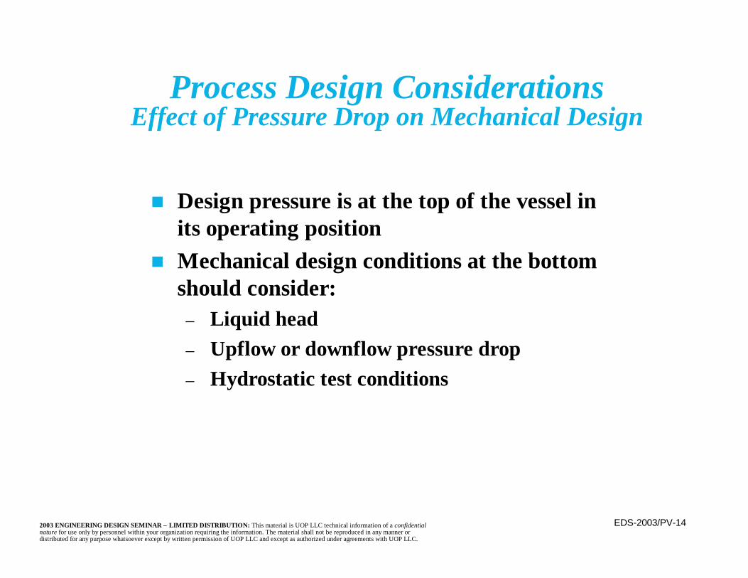
Process Design ConsiderationsEffect of Pressure Drop on Mechanical Design
n Design pressure is at the top of the vessel inits operating position
n Mechanical design conditions at the bottomshould consider:
– Liquid head– Upflow or downflow pressure drop– Hydrostatic test conditions

EDS-2003/PV-152003 ENGINEERING DESIGN SEMINAR – LIMITED DISTRIBUTION: This material is UOP LLC technical information of a confidentialnature for use only by personnel within your organization requiring the information. The material shall not be reproduced in any manner ordistributed for any purpose whatsoever except by written permission of UOP LLC and except as authorized under agreements with UOP LLC.
Process Design ConditionsTemperature Nomenclature
n Normal Operating– Highest temperature expected during the
equipment’s operating cycle, including startand end of run.
n Design Temperature– Normal operating temperature plus a margin
n If operation is cryogenic (cold), the margin isa minus value (usually -25°F). Alternativemargins may be considered where themetallurgy is affected.
EDS-2003/PV-162003 ENGINEERING DESIGN SEMINAR – LIMITED DISTRIBUTION: This material is UOP LLC technical information of a confidentialnature for use only by personnel within your organization requiring the information. The material shall not be reproduced in any manner ordistributed for any purpose whatsoever except by written permission of UOP LLC and except as authorized under agreements with UOP LLC.
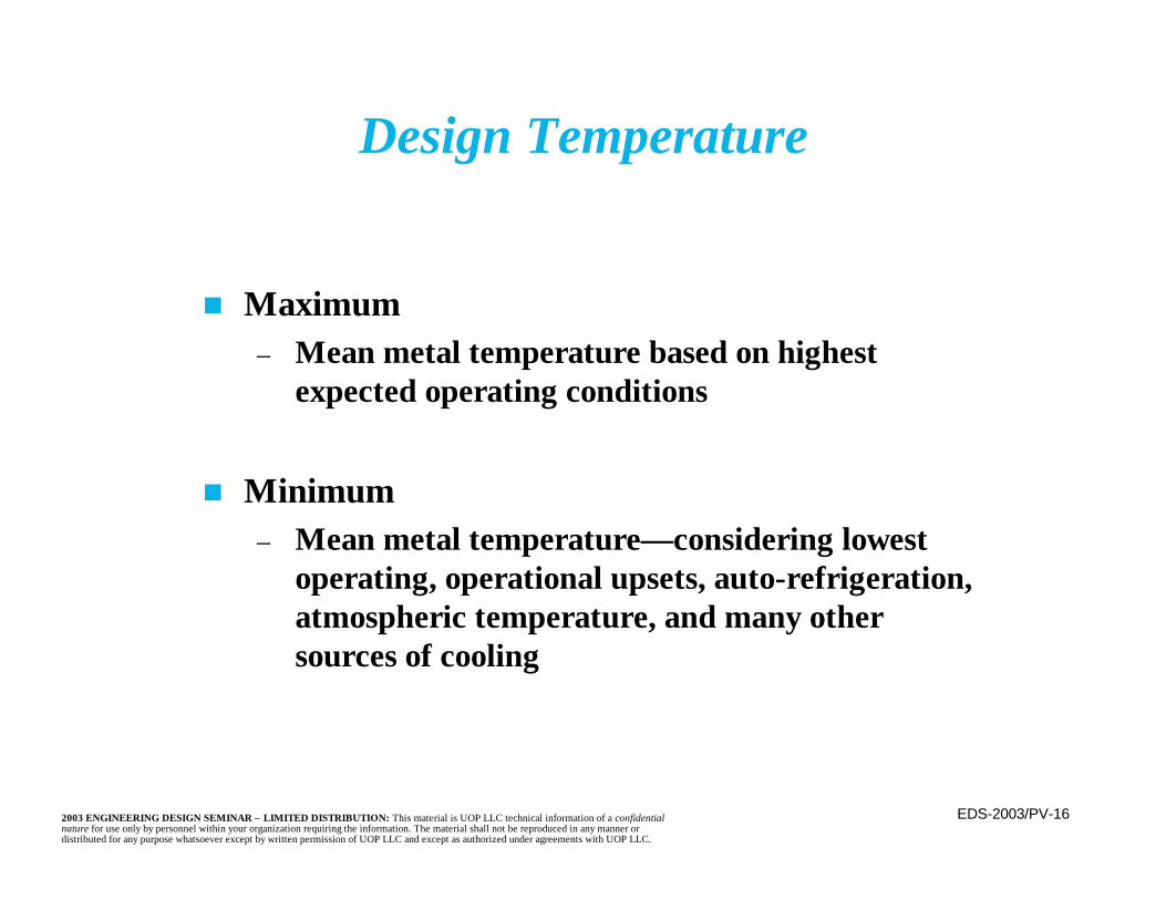
n Maximum– Mean metal temperature based on highest
expected operating conditions
n Minimum– Mean metal temperature— considering lowest
operating, operational upsets, auto-refrigeration,atmospheric temperature, and many othersources of cooling
Design Temperature
EDS-2003/PV-172003 ENGINEERING DESIGN SEMINAR – LIMITED DISTRIBUTION: This material is UOP LLC technical information of a confidentialnature for use only by personnel within your organization requiring the information. The material shall not be reproduced in any manner ordistributed for any purpose whatsoever except by written permission of UOP LLC and except as authorized under agreements with UOP LLC.
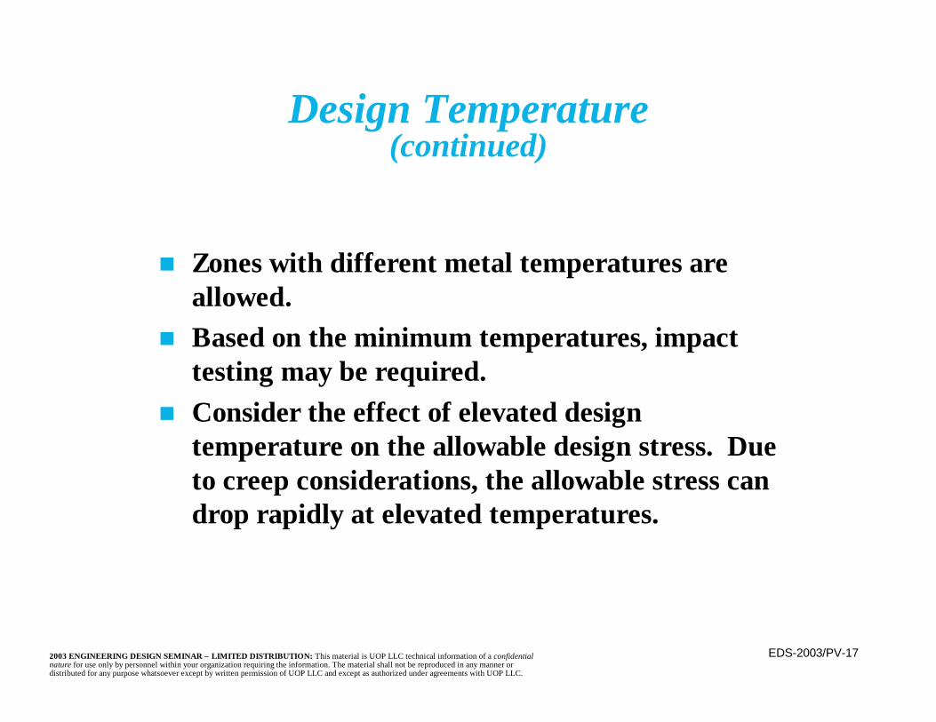
Design Temperature(continued)
n Zones with different metal temperatures areallowed.
n Based on the minimum temperatures, impacttesting may be required.
n Consider the effect of elevated designtemperature on the allowable design stress. Dueto creep considerations, the allowable stress candrop rapidly at elevated temperatures.
EDS-2003/PV-182003 ENGINEERING DESIGN SEMINAR – LIMITED DISTRIBUTION: This material is UOP LLC technical information of a confidentialnature for use only by personnel within your organization requiring the information. The material shall not be reproduced in any manner ordistributed for any purpose whatsoever except by written permission of UOP LLC and except as authorized under agreements with UOP LLC.
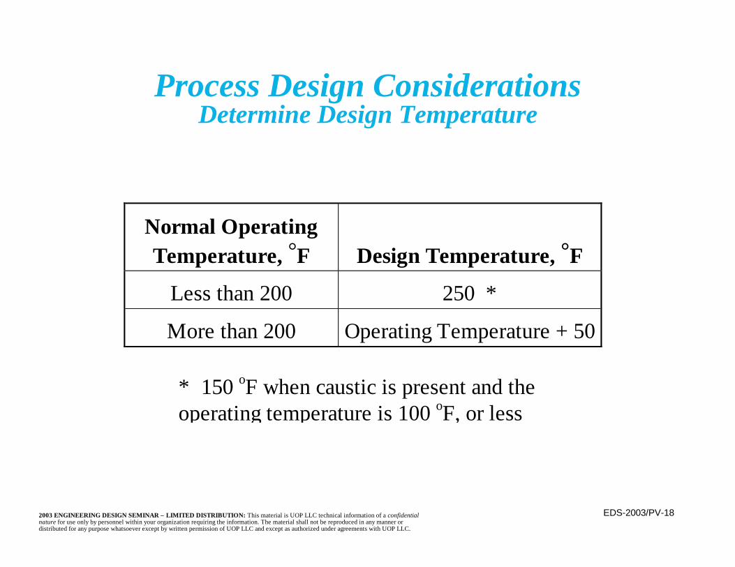
Process Design ConsiderationsDetermine Design Temperature
Normal OperatingTemperature, °F Design Temperature, °F
Less than 200 250 *
More than 200 Operating Temperature + 50
* 150 oF when caustic is present and theoperating temperature is 100 oF, or less

EDS-2003/PV-192003 ENGINEERING DESIGN SEMINAR – LIMITED DISTRIBUTION: This material is UOP LLC technical information of a confidentialnature for use only by personnel within your organization requiring the information. The material shall not be reproduced in any manner ordistributed for any purpose whatsoever except by written permission of UOP LLC and except as authorized under agreements with UOP LLC.
Process Design ConsiderationsSpecial Cases for Design Temperature
n Fractionators– Design temperature normally constant top to
bottom, based upon the highest operatingtemperature (which is generally at the bottom)
– Graduated for large delta T’s when the higherdesign temperature is greater than 650oF
n Cooler Failure– Failure of coolers upstream of equipment
could require a greater margin than 50°F
EDS-2003/PV-202003 ENGINEERING DESIGN SEMINAR – LIMITED DISTRIBUTION: This material is UOP LLC technical information of a confidentialnature for use only by personnel within your organization requiring the information. The material shall not be reproduced in any manner ordistributed for any purpose whatsoever except by written permission of UOP LLC and except as authorized under agreements with UOP LLC.
Process Design ConsiderationsSpecial Cases for Design Temperature (continued)
n Heat Exchanger Shells– Use higher of the inlet or outlet– Graduate if change in metallurgy possible on
large exchangersn Cold Wall Design
– Internally insulated vessels allow lower shelldesign temperature and possibly a lower andless expensive metallurgy
n Flange Classes– Watch the effect on the flange class when
setting the design temperature

EDS-2003/PV-212003 ENGINEERING DESIGN SEMINAR – LIMITED DISTRIBUTION: This material is UOP LLC technical information of a confidentialnature for use only by personnel within your organization requiring the information. The material shall not be reproduced in any manner ordistributed for any purpose whatsoever except by written permission of UOP LLC and except as authorized under agreements with UOP LLC.
Process Design ConsiderationsSpecial Cases for Design Temperature (continued)
n Short Term Elevated Temperature– Use a reduced margin (or no margin) when the
maximum temperature is a short termcondition (e.g., end of run (EOR)) only and isin the creep range of the material(s)
– In the creep range, the allowable stress dropsrapidly
• Creep is time dependent and not generallysignificant in the short term
n Design codes do not require or give guidelinesfor temperature or pressure design margins
EDS-2003/PV-222003 ENGINEERING DESIGN SEMINAR – LIMITED DISTRIBUTION: This material is UOP LLC technical information of a confidentialnature for use only by personnel within your organization requiring the information. The material shall not be reproduced in any manner ordistributed for any purpose whatsoever except by written permission of UOP LLC and except as authorized under agreements with UOP LLC.
Specified Design Conditions
n The specified design conditions are those resultingin the most severe head/shell requirements
– Generally the greatest temperature and greatestpressure
n If the greatest temperature and pressure do notact simultaneously, the governing case may notinclude either or both
n Different portions of the equipment may havedifferent design conditions
– Consider need to accommodate pressure testing
EDS-2003/PV-232003 ENGINEERING DESIGN SEMINAR – LIMITED DISTRIBUTION: This material is UOP LLC technical information of a confidentialnature for use only by personnel within your organization requiring the information. The material shall not be reproduced in any manner ordistributed for any purpose whatsoever except by written permission of UOP LLC and except as authorized under agreements with UOP LLC.
Overall Geometry
n The sphere is the most economical shape forpressure retention
– Used for some gas storage vessels, particularlyhigh pressure
n For process equipment, the need to fabricateand install internals, distribute and collectprocess material, and control the processleads to the need for a consistent cross-sectionrather than the constantly varying cross-section of a sphere

EDS-2003/PV-242003 ENGINEERING DESIGN SEMINAR – LIMITED DISTRIBUTION: This material is UOP LLC technical information of a confidentialnature for use only by personnel within your organization requiring the information. The material shall not be reproduced in any manner ordistributed for any purpose whatsoever except by written permission of UOP LLC and except as authorized under agreements with UOP LLC.

EDS-2003/PV-252003 ENGINEERING DESIGN SEMINAR – LIMITED DISTRIBUTION: This material is UOP LLC technical information of a confidentialnature for use only by personnel within your organization requiring the information. The material shall not be reproduced in any manner ordistributed for any purpose whatsoever except by written permission of UOP LLC and except as authorized under agreements with UOP LLC.
Overall Geometry(continued)
n Plot space restrictions (i.e. “footprint”) alsomake a sphere less attractive
n Fabrication costs may offset sphere’s materialthickness savings
n Shape of choice for process equipment is acylinder
n Most vessels are oriented vertically unlessthere is a specific (process) reason to beplaced horizontally (e.g., gravity separators)

EDS-2003/PV-262003 ENGINEERING DESIGN SEMINAR – LIMITED DISTRIBUTION: This material is UOP LLC technical information of a confidentialnature for use only by personnel within your organization requiring the information. The material shall not be reproduced in any manner ordistributed for any purpose whatsoever except by written permission of UOP LLC and except as authorized under agreements with UOP LLC.
Overall Geometry(continued)
n Vessel dimensions and orientation are controlled byprocess requirements (e.g., space velocity, fluiddistribution, catalyst contact, residence time, traydesign and spacing, etc.)
n Cylinder length to inside diameter ratio of 3 or 4 istypically used
– Provides good mix of inside volume, cross-sectionarea, and vessel cost (e.g., wall thickness)
n Minimum shell thickness, in inches, of (D+100)/1000is provided for structural stability
– D is the inside diameter, in inches
EDS-2003/PV-272003 ENGINEERING DESIGN SEMINAR – LIMITED DISTRIBUTION: This material is UOP LLC technical information of a confidentialnature for use only by personnel within your organization requiring the information. The material shall not be reproduced in any manner ordistributed for any purpose whatsoever except by written permission of UOP LLC and except as authorized under agreements with UOP LLC.
Overall Geometry(continued)
n Corrosion/erosion allowance is usually providedon the thickness
– Determined based upon internal atmosphere– Is usually 1/16 to 1/8 inch (1.5 to 3 mm)
n Inside diameter and length dimensions are set toincrements of 6 inches or 100 mm
– Matches commonly available head sizes and “can”lengths for the shell

EDS-2003/PV-282003 ENGINEERING DESIGN SEMINAR – LIMITED DISTRIBUTION: This material is UOP LLC technical information of a confidentialnature for use only by personnel within your organization requiring the information. The material shall not be reproduced in any manner ordistributed for any purpose whatsoever except by written permission of UOP LLC and except as authorized under agreements with UOP LLC.
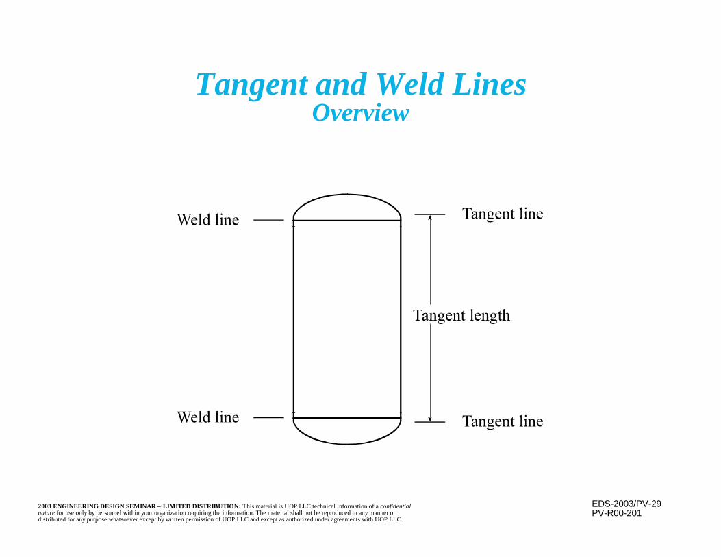
Tangent and Weld Lines
n Tangent Line– Point at which the head curvature begins
n Weld Line– Point at which the head and shell are welded
together
The weld line is very rarely the same point as thetangent line. This moves the weld to a point wherefit is easier (e.g., both sections are cylindrical) andaway from any stress concentrations present at thegeometrical joint.
EDS-2003/PV-292003 ENGINEERING DESIGN SEMINAR – LIMITED DISTRIBUTION: This material is UOP LLC technical information of a confidentialnature for use only by personnel within your organization requiring the information. The material shall not be reproduced in any manner ordistributed for any purpose whatsoever except by written permission of UOP LLC and except as authorized under agreements with UOP LLC.
PV-R00-201
Tangent and Weld LinesOverview
EDS-2003/PV-302003 ENGINEERING DESIGN SEMINAR – LIMITED DISTRIBUTION: This material is UOP LLC technical information of a confidentialnature for use only by personnel within your organization requiring the information. The material shall not be reproduced in any manner ordistributed for any purpose whatsoever except by written permission of UOP LLC and except as authorized under agreements with UOP LLC.
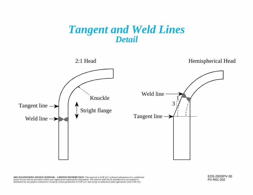
Tangent and Weld LinesDetail
PV-R01-202
Weld line
Tangent lineKnuckle
2:1 Head
Weld line
Tangent line
Hemispherical Head
31
Stright flange
EDS-2003/PV-312003 ENGINEERING DESIGN SEMINAR – LIMITED DISTRIBUTION: This material is UOP LLC technical information of a confidentialnature for use only by personnel within your organization requiring the information. The material shall not be reproduced in any manner ordistributed for any purpose whatsoever except by written permission of UOP LLC and except as authorized under agreements with UOP LLC.
Common Head Styles
n Hemisphericaln Ellipticaln Conicaln Flanged and Dishedn Torisphericaln Flat
Hemispherical and 2:1Elliptical are themost common.

EDS-2003/PV-322003 ENGINEERING DESIGN SEMINAR – LIMITED DISTRIBUTION: This material is UOP LLC technical information of a confidentialnature for use only by personnel within your organization requiring the information. The material shall not be reproduced in any manner ordistributed for any purpose whatsoever except by written permission of UOP LLC and except as authorized under agreements with UOP LLC.
n Hemispherical– Optimal pressure containing shape– Half as thick as the shell– No sharp radius bends (e.g. knuckles) or stress
concentration points– Minimizes thinning, cracking, and compression
concerns– Entire head is at one smooth, constant, curvature
Hemisphericalversus 2:1 Elliptical Heads
EDS-2003/PV-332003 ENGINEERING DESIGN SEMINAR – LIMITED DISTRIBUTION: This material is UOP LLC technical information of a confidentialnature for use only by personnel within your organization requiring the information. The material shall not be reproduced in any manner ordistributed for any purpose whatsoever except by written permission of UOP LLC and except as authorized under agreements with UOP LLC.
Hemisphericalversus 2:1 Elliptical Heads
(continued)
n Hemispherical (continued)– Joint with the shell is more complex– Greater contained volume than 2:1 elliptical– More surface area than 2:1 elliptical– More difficult to form or fabricate, fewer
potential vendors– Suitable for thick shells (> 2 inches) (from a cost
viewpoint)– Often fabricated rather than formed in one piece
EDS-2003/PV-342003 ENGINEERING DESIGN SEMINAR – LIMITED DISTRIBUTION: This material is UOP LLC technical information of a confidentialnature for use only by personnel within your organization requiring the information. The material shall not be reproduced in any manner ordistributed for any purpose whatsoever except by written permission of UOP LLC and except as authorized under agreements with UOP LLC.
Hemispherical vs. 2:1 Elliptical Heads(continued)
n 2:1 elliptical– Three dimensional elliptical geometry– Depth equals 1/2 the vessel radius– Same thickness as the shell– Easy butt weld detail at joint with the shell– Commonly available– Less volume and surface area than hemispherical– Knuckles are in hoop compression– Suitable for thin shells (< 2 inches) (from a cost
viewpoint)
EDS-2003/PV-352003 ENGINEERING DESIGN SEMINAR – LIMITED DISTRIBUTION: This material is UOP LLC technical information of a confidentialnature for use only by personnel within your organization requiring the information. The material shall not be reproduced in any manner ordistributed for any purpose whatsoever except by written permission of UOP LLC and except as authorized under agreements with UOP LLC.
Nozzle Details
n Although nearly any orientation is possible, forease of design and reinforcement, nozzles shouldbe perpendicular to the shell
n Although not prohibited by codes, avoid locatingnozzles in or near vessel weld seams
– Nozzle and any reinforcement will interfere withthe ability to inspect and NDE the vessel weld

EDS-2003/PV-362003 ENGINEERING DESIGN SEMINAR – LIMITED DISTRIBUTION: This material is UOP LLC technical information of a confidentialnature for use only by personnel within your organization requiring the information. The material shall not be reproduced in any manner ordistributed for any purpose whatsoever except by written permission of UOP LLC and except as authorized under agreements with UOP LLC.
Nozzle Details(continued)
n Locate nozzles so nozzle and its reinforcementare located within 80% of the head diameter
n Nozzle to shell welds are difficult to examine,especially to radiograph, because of the difficultyin accessing welds between two components at aright angle and the interference in the readingscaused by the geometrical changes
EDS-2003/PV-372003 ENGINEERING DESIGN SEMINAR – LIMITED DISTRIBUTION: This material is UOP LLC technical information of a confidentialnature for use only by personnel within your organization requiring the information. The material shall not be reproduced in any manner ordistributed for any purpose whatsoever except by written permission of UOP LLC and except as authorized under agreements with UOP LLC.
PV-R03-67A
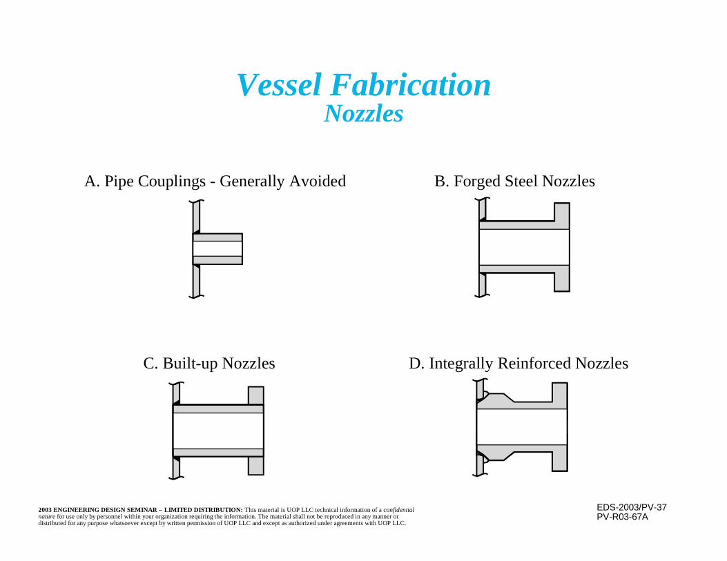
Vessel FabricationNozzles
C. Built-up Nozzles D. Integrally Reinforced Nozzles
A. Pipe Couplings - Generally Avoided B. Forged Steel Nozzles

EDS-2003/PV-382003 ENGINEERING DESIGN SEMINAR – LIMITED DISTRIBUTION: This material is UOP LLC technical information of a confidentialnature for use only by personnel within your organization requiring the information. The material shall not be reproduced in any manner ordistributed for any purpose whatsoever except by written permission of UOP LLC and except as authorized under agreements with UOP LLC.
Nozzle Details(continued)
n Nozzle to shell joint geometry (e.g., sharpcorners, sudden thickness and geometricalchanges) causes stress concentrations
n Welding effects (heating, cooling,metallurgical changes, heat affected zones)and geometric constraints also cause residualstress concentrations

EDS-2003/PV-392003 ENGINEERING DESIGN SEMINAR – LIMITED DISTRIBUTION: This material is UOP LLC technical information of a confidentialnature for use only by personnel within your organization requiring the information. The material shall not be reproduced in any manner ordistributed for any purpose whatsoever except by written permission of UOP LLC and except as authorized under agreements with UOP LLC.
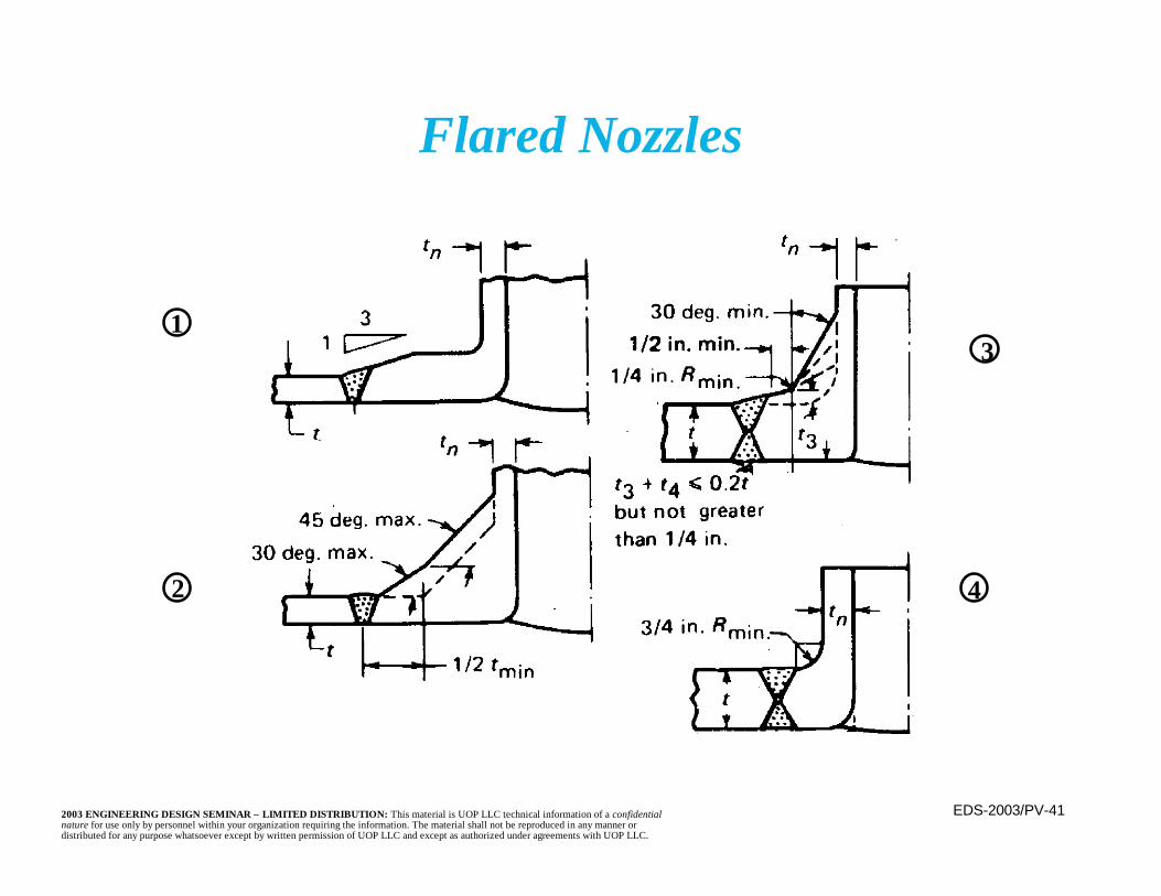
n To minimize effects of stress concentrationsand examination difficulty, flared nozzles aresometimes used for high pressure, cyclic, orelevated temperature (creep range) service
n This detail moves the weld away from thegeometry discontinuities and creates an easierto perform butt weld to the shell, withprobable improved weld quality
Nozzle Details(continued)
EDS-2003/PV-402003 ENGINEERING DESIGN SEMINAR – LIMITED DISTRIBUTION: This material is UOP LLC technical information of a confidentialnature for use only by personnel within your organization requiring the information. The material shall not be reproduced in any manner ordistributed for any purpose whatsoever except by written permission of UOP LLC and except as authorized under agreements with UOP LLC.
Nozzle Details(continued)
n Examination of the weld becomes easier andthe geometrical stress concentrations aremoved from the weld HAZ and are notadditive to the stress concentrations/residualstresses due to welding
n A smoothly contoured detail, free of stressconcentration points, is more reliably madefrom a forging than grinding a confined weld
n Flared nozzles are more expensive to produce
EDS-2003/PV-412003 ENGINEERING DESIGN SEMINAR – LIMITED DISTRIBUTION: This material is UOP LLC technical information of a confidentialnature for use only by personnel within your organization requiring the information. The material shall not be reproduced in any manner ordistributed for any purpose whatsoever except by written permission of UOP LLC and except as authorized under agreements with UOP LLC.
1
2
3
4
Flared Nozzles

EDS-2003/PV-422003 ENGINEERING DESIGN SEMINAR – LIMITED DISTRIBUTION: This material is UOP LLC technical information of a confidentialnature for use only by personnel within your organization requiring the information. The material shall not be reproduced in any manner ordistributed for any purpose whatsoever except by written permission of UOP LLC and except as authorized under agreements with UOP LLC.
Nozzle Details(continued)
n Nozzle attachments may be through the shellor butt welded to it
– Through shell• Welding may be performed and examined
from both sides; NDE is easier• Nozzle ID forms a uniform diameter,
smooth, unbroken single metallurgysurface through the shell

EDS-2003/PV-432003 ENGINEERING DESIGN SEMINAR – LIMITED DISTRIBUTION: This material is UOP LLC technical information of a confidentialnature for use only by personnel within your organization requiring the information. The material shall not be reproduced in any manner ordistributed for any purpose whatsoever except by written permission of UOP LLC and except as authorized under agreements with UOP LLC.
Nozzle Details(continued)
– Through shell (continued)• For thick shells, heat of welding may warp
nozzle; may be impractical for smallnozzles in thick shells
• Requires weld preparation of the shellplate (e.g., beveling)
• Connection tends to be stronger. Weld isplaced into shear by tension, bending,compressive, or torsional loads.
EDS-2003/PV-442003 ENGINEERING DESIGN SEMINAR – LIMITED DISTRIBUTION: This material is UOP LLC technical information of a confidentialnature for use only by personnel within your organization requiring the information. The material shall not be reproduced in any manner ordistributed for any purpose whatsoever except by written permission of UOP LLC and except as authorized under agreements with UOP LLC.
Nozzle Details(continued)
– Butt weld to shell surface• Smaller weld, less distortion possibility• Shell laminations are a concern, especially if
external loads are present• Access to the weld (for back welding or NDE)
from inside the nozzle may be impossible• Inner surface of the nozzle is broken; shell
opening must match nozzle ID• Connection tends to be weaker because the weld
is in tension due to tensile or bending loads.
EDS-2003/PV-452003 ENGINEERING DESIGN SEMINAR – LIMITED DISTRIBUTION: This material is UOP LLC technical information of a confidentialnature for use only by personnel within your organization requiring the information. The material shall not be reproduced in any manner ordistributed for any purpose whatsoever except by written permission of UOP LLC and except as authorized under agreements with UOP LLC.
Nozzle Neck Thickness
n Greater of:– A) Minimum thickness required for the nozzle
cylinder by the code design equations forpressure plus external loads, plus corrosion
– B) Smaller of• Minimum thickness of standard wall pipe
plus corrosion• Vessel shell or head thickness required for
pressure, plus corrosion

EDS-2003/PV-462003 ENGINEERING DESIGN SEMINAR – LIMITED DISTRIBUTION: This material is UOP LLC technical information of a confidentialnature for use only by personnel within your organization requiring the information. The material shall not be reproduced in any manner ordistributed for any purpose whatsoever except by written permission of UOP LLC and except as authorized under agreements with UOP LLC.
Codes and Standards
n Communicate design requirementsn Utilize know-how and technologyn Keep equipment costs lown Reduce insurance costs *n Reduce chance of legal entanglements *
* Due to the use of standard, recognized, designmethods and components.
The rules found in the design codes representmany man-years of experience. If used wisely,the code requirements can:
EDS-2003/PV-472003 ENGINEERING DESIGN SEMINAR – LIMITED DISTRIBUTION: This material is UOP LLC technical information of a confidentialnature for use only by personnel within your organization requiring the information. The material shall not be reproduced in any manner ordistributed for any purpose whatsoever except by written permission of UOP LLC and except as authorized under agreements with UOP LLC.
Design Codes
n Provide rules for the design of equipmentadequate for design conditions determined byothers
n Do not provide rules or guidance for thedetermination of design conditions
n Do not provide rules or guidance for thedetermination of the required material(s) ofconstruction or corrosion allowance
EDS-2003/PV-482003 ENGINEERING DESIGN SEMINAR – LIMITED DISTRIBUTION: This material is UOP LLC technical information of a confidentialnature for use only by personnel within your organization requiring the information. The material shall not be reproduced in any manner ordistributed for any purpose whatsoever except by written permission of UOP LLC and except as authorized under agreements with UOP LLC.
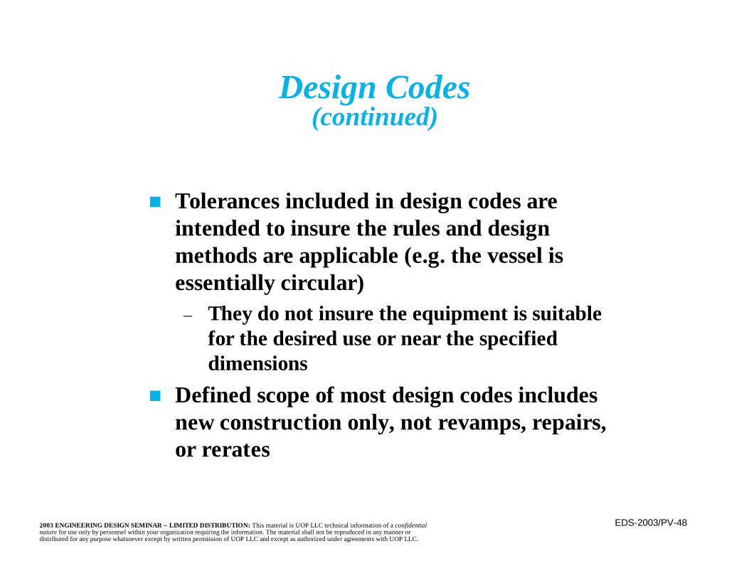
n Tolerances included in design codes areintended to insure the rules and designmethods are applicable (e.g. the vessel isessentially circular)
– They do not insure the equipment is suitablefor the desired use or near the specifieddimensions
n Defined scope of most design codes includesnew construction only, not revamps, repairs,or rerates
Design Codes(continued)
EDS-2003/PV-492003 ENGINEERING DESIGN SEMINAR – LIMITED DISTRIBUTION: This material is UOP LLC technical information of a confidentialnature for use only by personnel within your organization requiring the information. The material shall not be reproduced in any manner ordistributed for any purpose whatsoever except by written permission of UOP LLC and except as authorized under agreements with UOP LLC.
Design Codes(continued)
n Laws and regulations in force at the sitedetermine the Code that must be used.
n Laws and regulations may also specify theedition of the Code and could limit use ofreferenced or auxiliary documents (e.g., CodeCases).
EDS-2003/PV-502003 ENGINEERING DESIGN SEMINAR – LIMITED DISTRIBUTION: This material is UOP LLC technical information of a confidentialnature for use only by personnel within your organization requiring the information. The material shall not be reproduced in any manner ordistributed for any purpose whatsoever except by written permission of UOP LLC and except as authorized under agreements with UOP LLC.
n Provisions of a design code are an interrelated set ofdesign, fabrication, inspection, and testing requirements.For example, the use of a higher design stress may dependupon use of stringent material, analysis, examination, andtesting requirements. Therefore, different codes can arriveat different resulting wall thickness yet have equivalentdegrees of reliability (see following slide). Because theprovisions are interrelated, any selected code must be usedin its entirety. Provisions cannot be mixed from differentcodes. Use of particular codes is generally written into thenational or local laws of the plant site.
Code Use
EDS-2003/PV-512003 ENGINEERING DESIGN SEMINAR – LIMITED DISTRIBUTION: This material is UOP LLC technical information of a confidentialnature for use only by personnel within your organization requiring the information. The material shall not be reproduced in any manner ordistributed for any purpose whatsoever except by written permission of UOP LLC and except as authorized under agreements with UOP LLC.
PV-R00-02
Wal
l thi
ckne
ss: i
nche
s
Pressure: lbs per square inch
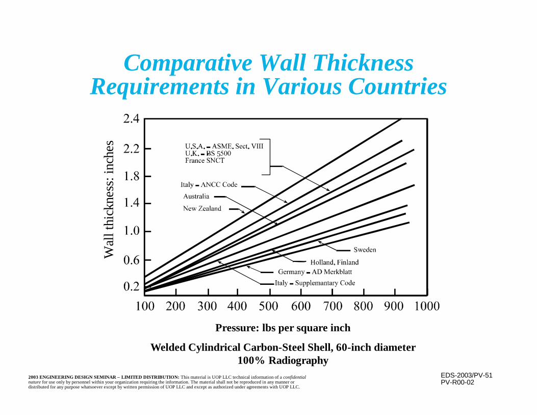
Welded Cylindrical Carbon-Steel Shell, 60-inch diameter100% Radiography
5
Comparative Wall ThicknessRequirements in Various Countries
EDS-2003/PV-522003 ENGINEERING DESIGN SEMINAR – LIMITED DISTRIBUTION: This material is UOP LLC technical information of a confidentialnature for use only by personnel within your organization requiring the information. The material shall not be reproduced in any manner ordistributed for any purpose whatsoever except by written permission of UOP LLC and except as authorized under agreements with UOP LLC.
Codes and StandardsASME Section I
n Used for steam generating equipment andcertain auxiliary equipment and piping
n Often used for power plants that cannotafford to be “down”; therefore, design a littlemore conservatism into them
n Uses factor of safety of 3.5n Maximum joint efficiency of 0.9n More expensive than Section VIII, Division 1
EDS-2003/PV-532003 ENGINEERING DESIGN SEMINAR – LIMITED DISTRIBUTION: This material is UOP LLC technical information of a confidentialnature for use only by personnel within your organization requiring the information. The material shall not be reproduced in any manner ordistributed for any purpose whatsoever except by written permission of UOP LLC and except as authorized under agreements with UOP LLC.
Codes and StandardsASME Section VIII, Division 1
n Used for most unfired refinery equipmentn Uses factor of safety of 3.5 against tensile failure
and 1.25 for 100,000 hour creep rupturen Limited to 3000 psi (less as a practical matter)n Rigorous evaluations of local, thermal, and
fatigue stresses are not usually explicitlyperformed
EDS-2003/PV-542003 ENGINEERING DESIGN SEMINAR – LIMITED DISTRIBUTION: This material is UOP LLC technical information of a confidentialnature for use only by personnel within your organization requiring the information. The material shall not be reproduced in any manner ordistributed for any purpose whatsoever except by written permission of UOP LLC and except as authorized under agreements with UOP LLC.
n Includes most vessels (or portions of vessels)subject to either an internal or external pressure
– Local laws and regulations determine applicabilityof the Code
n Does not include the following vessels within itsscope (in some cases they can be constructed andstamped in accordance with the Code if desired)
– Internal and external operating pressures do notexceed 15 psi
– Diameter, width, height, or cross-section diagonaldoes not exceed 6 inches (no limit on length)
Scope of ASME Section VIII, Division 1
EDS-2003/PV-552003 ENGINEERING DESIGN SEMINAR – LIMITED DISTRIBUTION: This material is UOP LLC technical information of a confidentialnature for use only by personnel within your organization requiring the information. The material shall not be reproduced in any manner ordistributed for any purpose whatsoever except by written permission of UOP LLC and except as authorized under agreements with UOP LLC.
Scope of ASME Section VIII, Division 1(continued)
n Vessels not included in scope of ASME VIII-1,(continued):
– Intended for human occupancy– Fired heaters– Equipment within scope of another section of the
ASME Code– Piping systems and components– Hot and/or pressurized water containment vessels
under certain conditions– Internal parts of rotating or reciprocating devices
where design considerations and stresses are derivedfrom the equipment’s functional requirements

EDS-2003/PV-562003 ENGINEERING DESIGN SEMINAR – LIMITED DISTRIBUTION: This material is UOP LLC technical information of a confidentialnature for use only by personnel within your organization requiring the information. The material shall not be reproduced in any manner ordistributed for any purpose whatsoever except by written permission of UOP LLC and except as authorized under agreements with UOP LLC.
Codes and StandardsASME Section VIII, Division 2
n Used for high pressure refinery equipmentn Uses factor of safety of 3 against tensile failuren Results in thinner vessels (compared to
Division 1)n Not permitted in the creep range of materialsn Requires additional design analysis (e.g., local
and thermal stress, fatigue) and qualitycontrol (e.g., full X-ray, stringent materialrequirements)
EDS-2003/PV-572003 ENGINEERING DESIGN SEMINAR – LIMITED DISTRIBUTION: This material is UOP LLC technical information of a confidentialnature for use only by personnel within your organization requiring the information. The material shall not be reproduced in any manner ordistributed for any purpose whatsoever except by written permission of UOP LLC and except as authorized under agreements with UOP LLC.
Codes and StandardsASME Section VIII, Division 2 (continued)
n More difficult to re-evaluate for futureoperating condition changes
n Limited fabricatorsn Material and fabrication costs (welding,
rolling) are lower, as are transportation,erection, and support costs
– Partly offset by analysis, design, and qualitycontrol expenses

EDS-2003/PV-582003 ENGINEERING DESIGN SEMINAR – LIMITED DISTRIBUTION: This material is UOP LLC technical information of a confidentialnature for use only by personnel within your organization requiring the information. The material shall not be reproduced in any manner ordistributed for any purpose whatsoever except by written permission of UOP LLC and except as authorized under agreements with UOP LLC.
UOP GuidelinesUse of ASME Section VIII Division 2
PV-R00-01
Based upon an allowable stress = 17,000 psi
Des
ign
Pres
sure
(psi
g)
Diameter (feet)
(thickness >4”)
(thickness <2”)
EDS-2003/PV-592003 ENGINEERING DESIGN SEMINAR – LIMITED DISTRIBUTION: This material is UOP LLC technical information of a confidentialnature for use only by personnel within your organization requiring the information. The material shall not be reproduced in any manner ordistributed for any purpose whatsoever except by written permission of UOP LLC and except as authorized under agreements with UOP LLC.
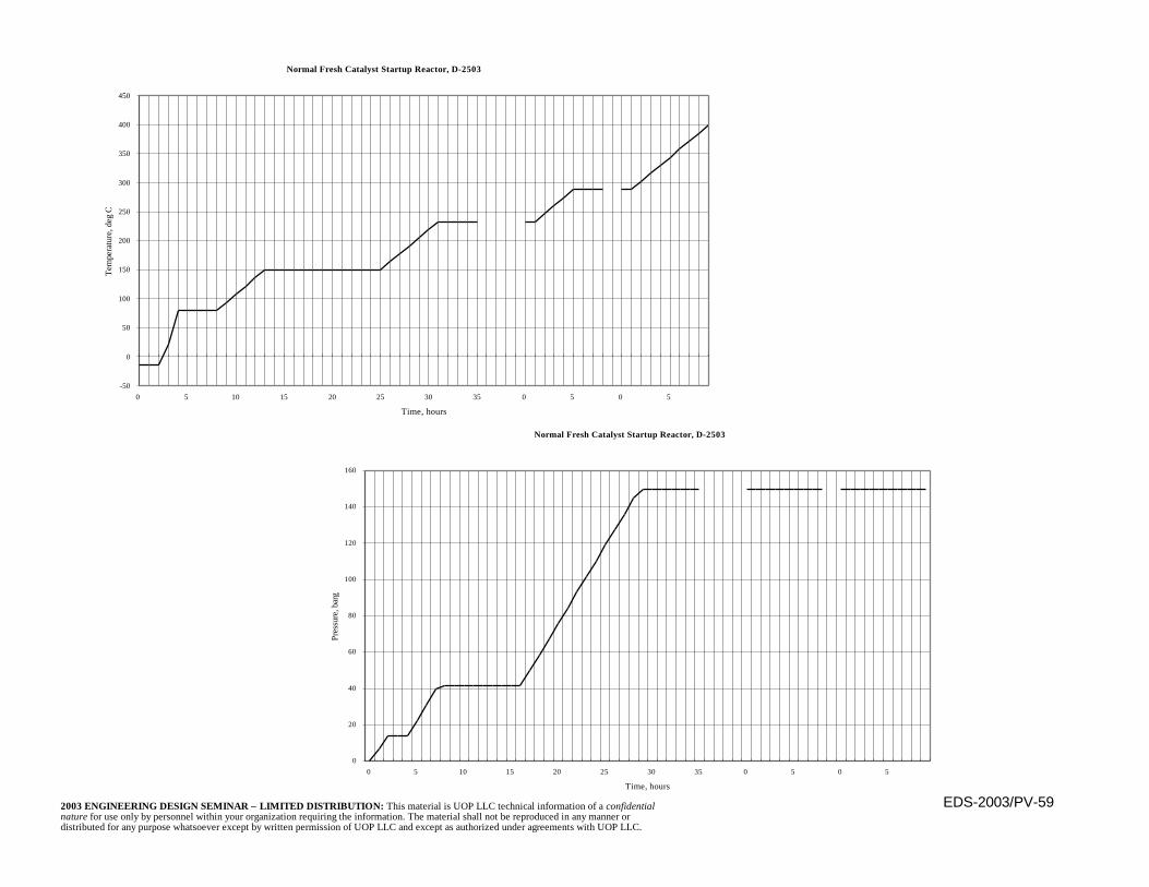
-50
0
50
100
150
200
250
300
350
400
450
0 5 10 15 20 25 30 35 0 5 0 5
Time, hours
Tem
pera
ture
, deg
C
Normal Fresh Catalyst Startup Reactor, D-2503
Normal Fresh Catalyst Startup Reactor, D-2503
0
20
40
60
80
100
120
140
160
0 5 10 15 20 25 30 35 0 5 0 5
Time, hours
Pres
sure
, bar
g
EDS-2003/PV-602003 ENGINEERING DESIGN SEMINAR – LIMITED DISTRIBUTION: This material is UOP LLC technical information of a confidentialnature for use only by personnel within your organization requiring the information. The material shall not be reproduced in any manner ordistributed for any purpose whatsoever except by written permission of UOP LLC and except as authorized under agreements with UOP LLC.
Codes and StandardsASME Section VIII, Division 3
n For ultra high pressure equipment (>10,000 psi)n High strength materialsn Material toughness requirementsn Fatigue analysis requiredn Refinery equipment does not fall within its scope

EDS-2003/PV-612003 ENGINEERING DESIGN SEMINAR – LIMITED DISTRIBUTION: This material is UOP LLC technical information of a confidentialnature for use only by personnel within your organization requiring the information. The material shall not be reproduced in any manner ordistributed for any purpose whatsoever except by written permission of UOP LLC and except as authorized under agreements with UOP LLC.
Codes and StandardsASME Code Cases and Interpretations
n Code Cases are auxiliary to the PressureVessel and Nuclear Sections of the ASMECode. If accepted by the local governingbody they carry the legal weight andauthority of the Code.
n Interpretations are committee responses toquestions but carry no legal weight. Theyexist for many Sections of the Code.
EDS-2003/PV-622003 ENGINEERING DESIGN SEMINAR – LIMITED DISTRIBUTION: This material is UOP LLC technical information of a confidentialnature for use only by personnel within your organization requiring the information. The material shall not be reproduced in any manner ordistributed for any purpose whatsoever except by written permission of UOP LLC and except as authorized under agreements with UOP LLC.
Codes and StandardsNon-Code Vessels
n Applicable to atmospheric vessels handlingwater and injection chemicals
n Nominal cost savings– No Code shop– No Code stamp
n Must still be safely constructed— oftencomplies with Code details
EDS-2003/PV-632003 ENGINEERING DESIGN SEMINAR – LIMITED DISTRIBUTION: This material is UOP LLC technical information of a confidentialnature for use only by personnel within your organization requiring the information. The material shall not be reproduced in any manner ordistributed for any purpose whatsoever except by written permission of UOP LLC and except as authorized under agreements with UOP LLC.
Codes and StandardsOther Related Codes and Standards
n API Standard 620, Large Low Pressure StorageTanks, Pressure 0.5 to 15 psig
n API Standard 650, Welded Storage Tanks,Pressures up to 0.5 psig
n ASME B31.3, Process Pipingn ASME B16.5, Pipe Flanges and Flanged Fittingsn ASME B16.47, Large Diameter Steel Flanges
NPS26 Through NPS60n TEMA for Heat Exchangersn Local codes if more stringent
EDS-2003/PV-642003 ENGINEERING DESIGN SEMINAR – LIMITED DISTRIBUTION: This material is UOP LLC technical information of a confidentialnature for use only by personnel within your organization requiring the information. The material shall not be reproduced in any manner ordistributed for any purpose whatsoever except by written permission of UOP LLC and except as authorized under agreements with UOP LLC.
n Scope of the familiar design codes covers newconstruction only
– For repairs and alterations (revamps), otherdocuments govern
n As with codes for new construction, theapplicable document depends upon local lawsand regulations
n Two common documents are:– NB23 - National Board Inspection Code– API 510 - Pressure Vessel Inspection Code,
Maintenance, Inspection, Rating, Repair, andAlteration
Code for Repairs and Alterations

EDS-2003/PV-652003 ENGINEERING DESIGN SEMINAR – LIMITED DISTRIBUTION: This material is UOP LLC technical information of a confidentialnature for use only by personnel within your organization requiring the information. The material shall not be reproduced in any manner ordistributed for any purpose whatsoever except by written permission of UOP LLC and except as authorized under agreements with UOP LLC.
UOP Standard Specifications
n UOP Standard Specifications for pressurevessels augment the codes
n Are organized on the basis of the material ofconstruction
n Most commonly used are:– 3–11 Pressure Vessels— Carbon Steel– 3–12 Pressure Vessels— Low Alloy Steel– 3–17 Pressure Vessels— ASME Section VIII
Division 2

EDS-2003/PV-662003 ENGINEERING DESIGN SEMINAR – LIMITED DISTRIBUTION: This material is UOP LLC technical information of a confidentialnature for use only by personnel within your organization requiring the information. The material shall not be reproduced in any manner ordistributed for any purpose whatsoever except by written permission of UOP LLC and except as authorized under agreements with UOP LLC.
ASME Versus ASTM Materials
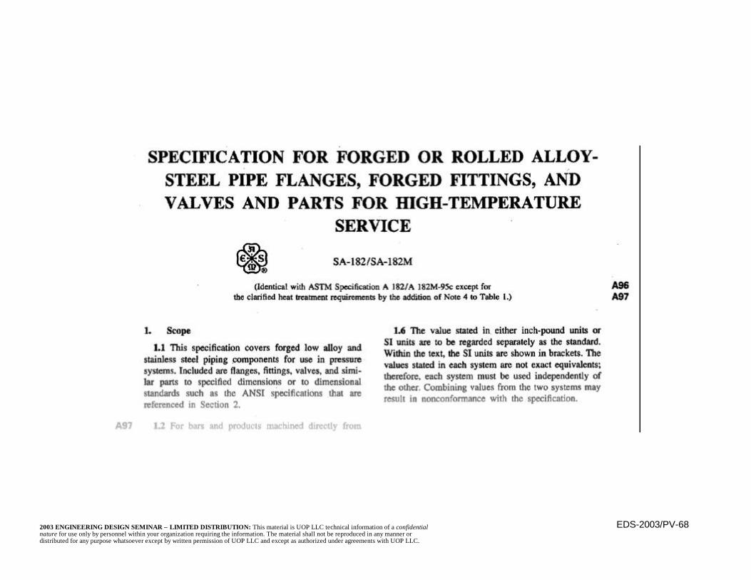
n ASTM materials are prefaced with “A” (e.g.A387); ASME materials are prefaced with“SA” (e.g. SA387)
n Are normally no significant differencesbetween the materials
– Any differences are noted in the ASME listings(Section II of the ASME Code)
EDS-2003/PV-672003 ENGINEERING DESIGN SEMINAR – LIMITED DISTRIBUTION: This material is UOP LLC technical information of a confidentialnature for use only by personnel within your organization requiring the information. The material shall not be reproduced in any manner ordistributed for any purpose whatsoever except by written permission of UOP LLC and except as authorized under agreements with UOP LLC.
ASME Versus ASTM Materials(continued)
n ASME materials (i.e. those designated with“SA”) must be used for fabrication accordingto the ASME Pressure Vessel Code
n ASTM materials are used for most other uses,including piping conforming to ASME B31.3
EDS-2003/PV-682003 ENGINEERING DESIGN SEMINAR – LIMITED DISTRIBUTION: This material is UOP LLC technical information of a confidentialnature for use only by personnel within your organization requiring the information. The material shall not be reproduced in any manner ordistributed for any purpose whatsoever except by written permission of UOP LLC and except as authorized under agreements with UOP LLC.

EDS-2003/PV-692003 ENGINEERING DESIGN SEMINAR – LIMITED DISTRIBUTION: This material is UOP LLC technical information of a confidentialnature for use only by personnel within your organization requiring the information. The material shall not be reproduced in any manner ordistributed for any purpose whatsoever except by written permission of UOP LLC and except as authorized under agreements with UOP LLC.
Low Temperature Requirements
n At low temperatures, many materials maybecome brittle
– ASME Code contains additional requirementsfor these materials depending upon theapplicable MDMT
n MDMT stands for Minimum Design MetalTemperature
– Is the lowest mean temperature of the metal (notthe internal fluid) considering many factors,including operating temperature, low ambienttemperature, and auto refrigeration
EDS-2003/PV-702003 ENGINEERING DESIGN SEMINAR – LIMITED DISTRIBUTION: This material is UOP LLC technical information of a confidentialnature for use only by personnel within your organization requiring the information. The material shall not be reproduced in any manner ordistributed for any purpose whatsoever except by written permission of UOP LLC and except as authorized under agreements with UOP LLC.
Low Temperature Requirements(continued)
n Application of additional requirementsdepends upon the material, MDMT, andthickness
n Figure UCS-66 of ASME Section VIIIDivision 1 is used to determine if Charpy V-notch testing is required
EDS-2003/PV-712003 ENGINEERING DESIGN SEMINAR – LIMITED DISTRIBUTION: This material is UOP LLC technical information of a confidentialnature for use only by personnel within your organization requiring the information. The material shall not be reproduced in any manner ordistributed for any purpose whatsoever except by written permission of UOP LLC and except as authorized under agreements with UOP LLC.
Low Temperature Requirements(continued)
n If required by Figure UCS-66, materials mustexhibit minimum Charpy V-notch impact testvalues when tested at the MDMT
n Exemptions and exceptions exist for thincarbon steel vessels, low stressed materials,and heat treated items if heat treatment is nototherwise required
EDS-2003/PV-722003 ENGINEERING DESIGN SEMINAR – LIMITED DISTRIBUTION: This material is UOP LLC technical information of a confidentialnature for use only by personnel within your organization requiring the information. The material shall not be reproduced in any manner ordistributed for any purpose whatsoever except by written permission of UOP LLC and except as authorized under agreements with UOP LLC.
MDMT Determination
n The MDMT shown by UOP is the lowest of thefollowing temperatures:
– Minimum operating temperature minus 25°F– Lowest average ambient temperature for a 24
hour period– Auto-refrigeration temperature determined by
flashing the material to 40 percent of designpressure
n This method of determining the MDMT tendsto be conservative because the surroundingfluid temperature, not the actual metaltemperature, is used.
EDS-2003/PV-732003 ENGINEERING DESIGN SEMINAR – LIMITED DISTRIBUTION: This material is UOP LLC technical information of a confidentialnature for use only by personnel within your organization requiring the information. The material shall not be reproduced in any manner ordistributed for any purpose whatsoever except by written permission of UOP LLC and except as authorized under agreements with UOP LLC.
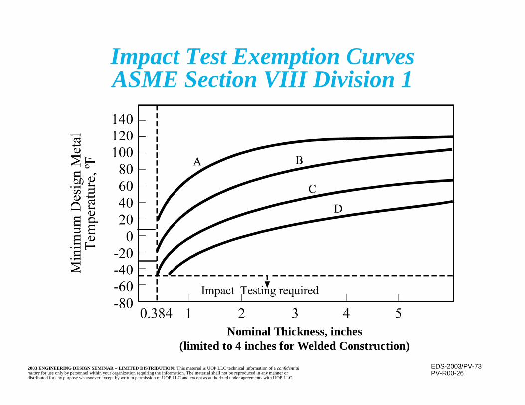
Impact Test Exemption CurvesASME Section VIII Division 1
PV-R00-26
Nominal Thickness, inches(limited to 4 inches for Welded Construction)
EDS-2003/PV-742003 ENGINEERING DESIGN SEMINAR – LIMITED DISTRIBUTION: This material is UOP LLC technical information of a confidentialnature for use only by personnel within your organization requiring the information. The material shall not be reproduced in any manner ordistributed for any purpose whatsoever except by written permission of UOP LLC and except as authorized under agreements with UOP LLC.
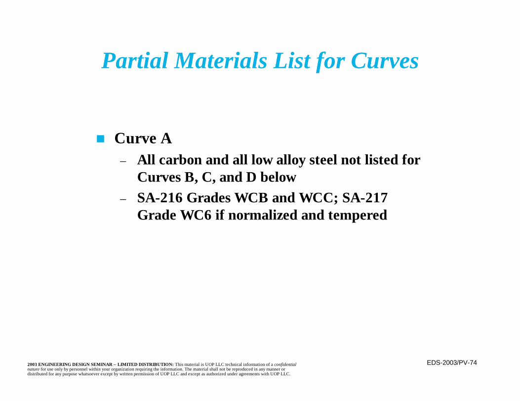
Partial Materials List for Curves
n Curve A– All carbon and all low alloy steel not listed for
Curves B, C, and D below– SA-216 Grades WCB and WCC; SA-217
Grade WC6 if normalized and tempered

EDS-2003/PV-752003 ENGINEERING DESIGN SEMINAR – LIMITED DISTRIBUTION: This material is UOP LLC technical information of a confidentialnature for use only by personnel within your organization requiring the information. The material shall not be reproduced in any manner ordistributed for any purpose whatsoever except by written permission of UOP LLC and except as authorized under agreements with UOP LLC.
Partial Materials List for Curves(continued)
n Curve B– SA-216 Grade WCA if normalized and tempered– SA-216 Grades WCB and WCC for thickness
not exceeding 2 inches, etc– SA-217 Grade WC9 if normalized and tempered– SA-285 Grades A and B– SA-515 Grade 60– SA-516 Grades 65 and 70 if not normalized

EDS-2003/PV-762003 ENGINEERING DESIGN SEMINAR – LIMITED DISTRIBUTION: This material is UOP LLC technical information of a confidentialnature for use only by personnel within your organization requiring the information. The material shall not be reproduced in any manner ordistributed for any purpose whatsoever except by written permission of UOP LLC and except as authorized under agreements with UOP LLC.
Partial Materials List for Curves(continued)
n Curve C– SA-182 Grades 21 and 22 if normalized and
tempered– SA-336 F21 and F22 if normalized and tempered– SA-387 Grades 21 and 22 if normalized and
tempered– SA-516 Grades 55 and 60 if not normalized
EDS-2003/PV-772003 ENGINEERING DESIGN SEMINAR – LIMITED DISTRIBUTION: This material is UOP LLC technical information of a confidentialnature for use only by personnel within your organization requiring the information. The material shall not be reproduced in any manner ordistributed for any purpose whatsoever except by written permission of UOP LLC and except as authorized under agreements with UOP LLC.
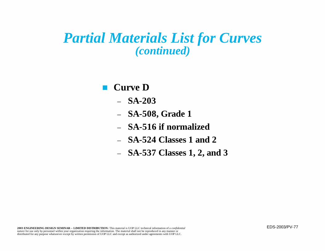
Partial Materials List for Curves(continued)
n Curve D– SA-203– SA-508, Grade 1– SA-516 if normalized– SA-524 Classes 1 and 2– SA-537 Classes 1, 2, and 3
EDS-2003/PV-782003 ENGINEERING DESIGN SEMINAR – LIMITED DISTRIBUTION: This material is UOP LLC technical information of a confidentialnature for use only by personnel within your organization requiring the information. The material shall not be reproduced in any manner ordistributed for any purpose whatsoever except by written permission of UOP LLC and except as authorized under agreements with UOP LLC.
PV-R01-27
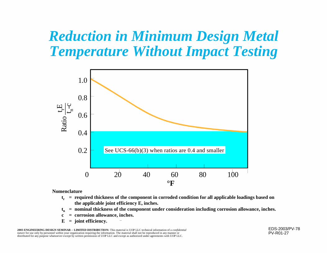
Nomenclaturetr = required thickness of the component in corroded condition for all applicable loadings based on
the applicable joint efficiency E, inches.tn = nominal thickness of the component under consideration including corrosion allowance, inches.c = corrosion allowance, inches.E = joint efficiency.
°F
Reduction in Minimum Design MetalTemperature Without Impact Testing
0
1.0
0.8
0.6
0.4
0.2
20 40 60 80 100
See UCS-66(b)(3) when ratios are 0.4 and smaller
Rat
io t rE t n-
c
EDS-2003/PV-792003 ENGINEERING DESIGN SEMINAR – LIMITED DISTRIBUTION: This material is UOP LLC technical information of a confidentialnature for use only by personnel within your organization requiring the information. The material shall not be reproduced in any manner ordistributed for any purpose whatsoever except by written permission of UOP LLC and except as authorized under agreements with UOP LLC.
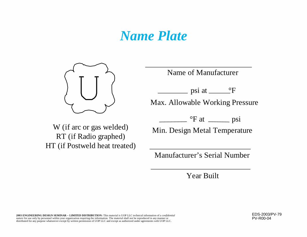
W (if arc or gas welded)RT (if Radio graphed)
HT (if Postweld heat treated)
PV-R00-04
Name of Manufacturer
psi at °FMax. Allowable Working Pressure
Min. Design Metal Temperature
Manufacturer’s Serial Number
Year Built
°F at psi
Name Plate
EDS-2003/PV-802003 ENGINEERING DESIGN SEMINAR – LIMITED DISTRIBUTION: This material is UOP LLC technical information of a confidentialnature for use only by personnel within your organization requiring the information. The material shall not be reproduced in any manner ordistributed for any purpose whatsoever except by written permission of UOP LLC and except as authorized under agreements with UOP LLC.
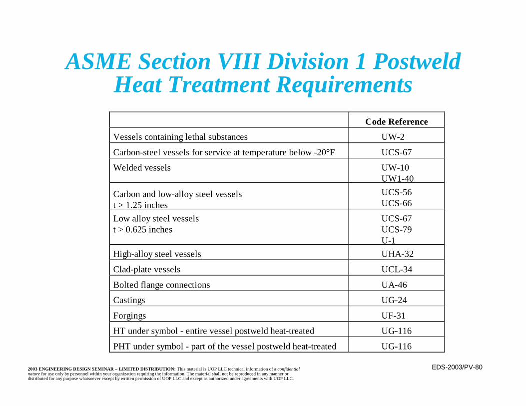
ASME Section VIII Division 1 PostweldHeat Treatment Requirements
Code Reference
Vessels containing lethal substances UW-2
Carbon-steel vessels for service at temperature below -20°F UCS-67
Welded vessels UW-10UW1-40
Carbon and low-alloy steel vesselst > 1.25 inches
UCS-56UCS-66
Low alloy steel vesselst > 0.625 inches
UCS-67UCS-79U-1
High-alloy steel vessels UHA-32
Clad-plate vessels UCL-34
Bolted flange connections UA-46
Castings UG-24
Forgings UF-31
HT under symbol - entire vessel postweld heat-treated UG-116
PHT under symbol - part of the vessel postweld heat-treated UG-116
EDS-2003/PV-812003 ENGINEERING DESIGN SEMINAR – LIMITED DISTRIBUTION: This material is UOP LLC technical information of a confidentialnature for use only by personnel within your organization requiring the information. The material shall not be reproduced in any manner ordistributed for any purpose whatsoever except by written permission of UOP LLC and except as authorized under agreements with UOP LLC.
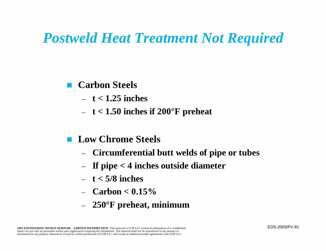
n Carbon Steels– t < 1.25 inches– t < 1.50 inches if 200°F preheat
n Low Chrome Steels– Circumferential butt welds of pipe or tubes– If pipe < 4 inches outside diameter– t < 5/8 inches– Carbon < 0.15%– 250°F preheat, minimum
Postweld Heat Treatment Not Required
EDS-2003/PV-822003 ENGINEERING DESIGN SEMINAR – LIMITED DISTRIBUTION: This material is UOP LLC technical information of a confidentialnature for use only by personnel within your organization requiring the information. The material shall not be reproduced in any manner ordistributed for any purpose whatsoever except by written permission of UOP LLC and except as authorized under agreements with UOP LLC.
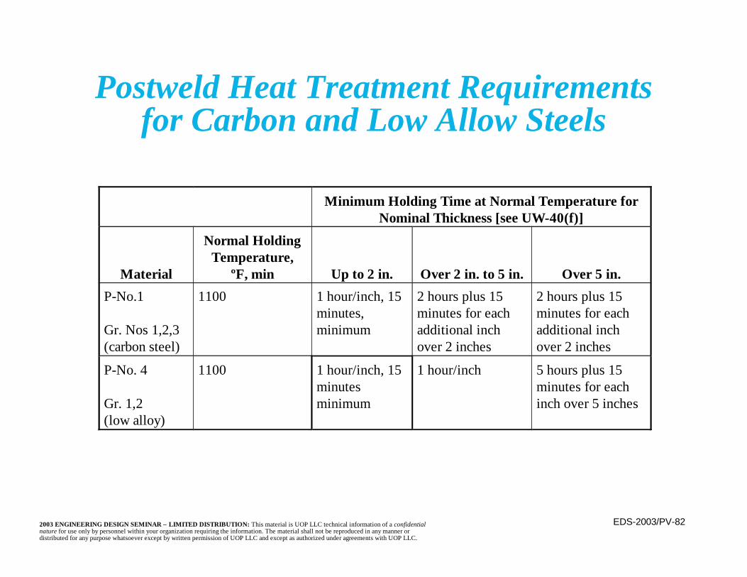
Postweld Heat Treatment Requirementsfor Carbon and Low Allow Steels
Minimum Holding Time at Normal Temperature forNominal Thickness [see UW-40(f)]
Material
Normal HoldingTemperature,
ºF, min Up to 2 in. Over 2 in. to 5 in. Over 5 in.
P-No.1
Gr. Nos 1,2,3(carbon steel)
1100 1 hour/inch, 15minutes,minimum
2 hours plus 15minutes for eachadditional inchover 2 inches
2 hours plus 15minutes for eachadditional inchover 2 inches
P-No. 4
Gr. 1,2(low alloy)
1100 1 hour/inch, 15minutesminimum
1 hour/inch 5 hours plus 15minutes for eachinch over 5 inches
EDS-2003/PV-832003 ENGINEERING DESIGN SEMINAR – LIMITED DISTRIBUTION: This material is UOP LLC technical information of a confidentialnature for use only by personnel within your organization requiring the information. The material shall not be reproduced in any manner ordistributed for any purpose whatsoever except by written permission of UOP LLC and except as authorized under agreements with UOP LLC.
Non-Destructive Examination Methods
n Visual– Most economical– Most versatile– Requires an experienced inspector– Detects surface imperfections only
n Dye Penetrant (PT)– Places a contrasting dye over the weld surface, then
wiped clean– Surface imperfections retain the dye– Apply a developer to make dye visible– Detects surface imperfections only
Nondestructive examination (NDE) is a quality assurancetool used to check welds for flaws. This results in safervessels and allows use of higher joint efficiencies; therefore,thinner shells. Methods of NDE include:
EDS-2003/PV-842003 ENGINEERING DESIGN SEMINAR – LIMITED DISTRIBUTION: This material is UOP LLC technical information of a confidentialnature for use only by personnel within your organization requiring the information. The material shall not be reproduced in any manner ordistributed for any purpose whatsoever except by written permission of UOP LLC and except as authorized under agreements with UOP LLC.
Non-Destructive Examination Methods(continued)
n Magnetic Particle (MT)– Metallic particles are sprinkled on the surface
and magnetic poles are supplied by an electriccurrent, creating a magnetic field
– Particles align with the magnetic field– Orientation of the particles indicates surface and
very slightly subsurface imperfections– May use fluorescent particles in a liquid
suspension to increase visibility and ease ofparticle movement
– Material must be magnetic and surface must behorizontal
– Accidental arc strikes possible
EDS-2003/PV-852003 ENGINEERING DESIGN SEMINAR – LIMITED DISTRIBUTION: This material is UOP LLC technical information of a confidentialnature for use only by personnel within your organization requiring the information. The material shall not be reproduced in any manner ordistributed for any purpose whatsoever except by written permission of UOP LLC and except as authorized under agreements with UOP LLC.
Non-Destructive Examination Methods(continued)
n Radiography (RT)– Detects many types of subsurface
imperfections, lack of fusion, slag inclusion,porosity, etc in addition to cracks
– Dangerous to perform• May require an isolated or roped off area
and be done at night or other times whenpeople are not present
– Requires access to both sides of the examinedsurface and clearance from obstructions in theimmediate vicinity
EDS-2003/PV-862003 ENGINEERING DESIGN SEMINAR – LIMITED DISTRIBUTION: This material is UOP LLC technical information of a confidentialnature for use only by personnel within your organization requiring the information. The material shall not be reproduced in any manner ordistributed for any purpose whatsoever except by written permission of UOP LLC and except as authorized under agreements with UOP LLC.
Non-Destructive Examination Methods(continued)
n Radiography (RT) (continued)– Generally requires an experienced, specialty
contractor– Can examine the full length or a portion of the
length (i.e. spot) of welds– Provides a permanent record in the form of a
film image– Difficult to perform in the field– For field inspections, gamma rays are often
substituted for X-rays

EDS-2003/PV-872003 ENGINEERING DESIGN SEMINAR – LIMITED DISTRIBUTION: This material is UOP LLC technical information of a confidentialnature for use only by personnel within your organization requiring the information. The material shall not be reproduced in any manner ordistributed for any purpose whatsoever except by written permission of UOP LLC and except as authorized under agreements with UOP LLC.
ASME Section VIII Division 1Full Radiographic Requirements
Carbon and Low-Alloy Steels
P Number and Group Number – Metals When Thickness Exceeds
P = 1 Group 11 21 3
Carbon steels
1.25 in
P = 3 Group 13 23 3
Alloy steels with 0.75 maximum chromium and those with 2.00maximum total alloy
0.75 in.
P = 4 Group 14 2
Alloy steels with 0.75 to 2.00 chromium and those with 2.75maximum total alloy
0.625 in.
P = 5A Group 15A 2
Alloy steels with 10.00 maximum total alloy
0.0 in.
P = 9A Group 19B 1
Nickel alloy steels
0.625 in.
P = 10A Group 110F 6
0.75 in.
P = 10B Group 210C 3
Other alloy steels
0.625 in.

EDS-2003/PV-882003 ENGINEERING DESIGN SEMINAR – LIMITED DISTRIBUTION: This material is UOP LLC technical information of a confidentialnature for use only by personnel within your organization requiring the information. The material shall not be reproduced in any manner ordistributed for any purpose whatsoever except by written permission of UOP LLC and except as authorized under agreements with UOP LLC.
Non-Destructive Examination Methods(continued)
n Ultrasonic (UT)– Uses reflection of sound waves to detect subsurface
flaws– Used to measure thickness– Access required from only one side– Not dangerous– Requires experienced operator to interpret results– Requires smooth, clean surface (including grinding
of welds)– Requires frequent calibration and a calibration
block for the material being examined
EDS-2003/PV-892003 ENGINEERING DESIGN SEMINAR – LIMITED DISTRIBUTION: This material is UOP LLC technical information of a confidentialnature for use only by personnel within your organization requiring the information. The material shall not be reproduced in any manner ordistributed for any purpose whatsoever except by written permission of UOP LLC and except as authorized under agreements with UOP LLC.
Non-Destructive Examination Methods(continued)
n Ultrasonic (UT) (continued)– Use of angle beams eliminates some concern with
nearby obstructions– Straight beam is used for thickness determination– Can be performed while equipment is on stream– Use of computers allows creation of a permanent
record on a disk– May be difficult to use on thin shells and on
austenitic stainless or coarse grained steelsn Other specialty methods, including replication
and acoustic emission, are available
EDS-2003/PV-902003 ENGINEERING DESIGN SEMINAR – LIMITED DISTRIBUTION: This material is UOP LLC technical information of a confidentialnature for use only by personnel within your organization requiring the information. The material shall not be reproduced in any manner ordistributed for any purpose whatsoever except by written permission of UOP LLC and except as authorized under agreements with UOP LLC.
Non-Destructive Examination Methods
n New vessel examination– Uses all examination methods– RT and UT detect subsurface fabrication
flaws and cracks, allowing for correctionn In service examination
– New damage/flaws form at surface, detectableby visual, PT, or MT
– Cracks may grow from existing subsurfacedefects, detected by RT and UT
– Corrosion detected by visual and UT

EDS-2003/PV-912003 ENGINEERING DESIGN SEMINAR – LIMITED DISTRIBUTION: This material is UOP LLC technical information of a confidentialnature for use only by personnel within your organization requiring the information. The material shall not be reproduced in any manner ordistributed for any purpose whatsoever except by written permission of UOP LLC and except as authorized under agreements with UOP LLC.
Lethal Services
n Defined in ASME Section VIII Division 1,Section UW-2.
n Lethal is defined as “poisonous gases orliquids of such a nature that a very smallamount of the gas or of the vapor of the liquidmixed or unmixed with air is dangerous tolife when inhaled.”
n API has determined that refinery processes,including HF containing services, do notqualify as lethal services.

EDS-2003/PV-922003 ENGINEERING DESIGN SEMINAR – LIMITED DISTRIBUTION: This material is UOP LLC technical information of a confidentialnature for use only by personnel within your organization requiring the information. The material shall not be reproduced in any manner ordistributed for any purpose whatsoever except by written permission of UOP LLC and except as authorized under agreements with UOP LLC.
n Shells are formed from a series of cylinders buttwelded together
– Typically these “cans” are 8 feet (2.5 meters) long
n Two forming methods are common:– Rolled plate– Drum forging
Vessel FabricationMethods of Shell Fabrication
EDS-2003/PV-932003 ENGINEERING DESIGN SEMINAR – LIMITED DISTRIBUTION: This material is UOP LLC technical information of a confidentialnature for use only by personnel within your organization requiring the information. The material shall not be reproduced in any manner ordistributed for any purpose whatsoever except by written permission of UOP LLC and except as authorized under agreements with UOP LLC.
Vessel Fabrication Methods of Shell Fabrication (continued)
n Rolled Plate– Commonly available– Many potential fabricators– Unlimited vessel size– Includes at least one longitudinal weld seam– Longitudinal seams of neighboring sections
cannot be aligned– Difficult to form thick shells
EDS-2003/PV-942003 ENGINEERING DESIGN SEMINAR – LIMITED DISTRIBUTION: This material is UOP LLC technical information of a confidentialnature for use only by personnel within your organization requiring the information. The material shall not be reproduced in any manner ordistributed for any purpose whatsoever except by written permission of UOP LLC and except as authorized under agreements with UOP LLC.
Vessel Fabrication Methods of Shell Fabrication (continued)
n Rolled Plate (continued)– Distortions possible during rolling– Difficult to maintain a consistent diameter– May be difficult to match shapes of
neighboring sections– Tends to have a grain alignment in the
direction of rolling– Can be difficult to roll to a small radius of
curvature (relative to the thickness)
EDS-2003/PV-952003 ENGINEERING DESIGN SEMINAR – LIMITED DISTRIBUTION: This material is UOP LLC technical information of a confidentialnature for use only by personnel within your organization requiring the information. The material shall not be reproduced in any manner ordistributed for any purpose whatsoever except by written permission of UOP LLC and except as authorized under agreements with UOP LLC.
Vessel Fabrication Methods of Shell Fabrication (continued)
n Drum Forging– Excellent for thick shells; no thinning or
creation of stresses– No longitudinal weld seam– Close ID tolerance; can be machined to very
close tolerances– Good thickness and diameter control

EDS-2003/PV-962003 ENGINEERING DESIGN SEMINAR – LIMITED DISTRIBUTION: This material is UOP LLC technical information of a confidentialnature for use only by personnel within your organization requiring the information. The material shall not be reproduced in any manner ordistributed for any purpose whatsoever except by written permission of UOP LLC and except as authorized under agreements with UOP LLC.
Vessel Fabrication Methods of Shell Fabrication (continued)
n Drum Forging (continued)– Formed directly from ingot– Due to need to work with a hot ingot, potential
fabricators are limited– Limited diameters possible– Limited volume of shell section determined by
ingot volume– Material properties vary from surface to center
EDS-2003/PV-972003 ENGINEERING DESIGN SEMINAR – LIMITED DISTRIBUTION: This material is UOP LLC technical information of a confidentialnature for use only by personnel within your organization requiring the information. The material shall not be reproduced in any manner ordistributed for any purpose whatsoever except by written permission of UOP LLC and except as authorized under agreements with UOP LLC.
Multi-Layer Construction
n Considered for heavy wall vessels where thethickness makes other methods impractical orexpensive
n Shell is made of multiple thin layers of material– Layers may be wound (like a coil) or formed from
separate rings and shrink fit onto each other– Thinner plate is easier to form– Thin plates have more uniform material properties
EDS-2003/PV-982003 ENGINEERING DESIGN SEMINAR – LIMITED DISTRIBUTION: This material is UOP LLC technical information of a confidentialnature for use only by personnel within your organization requiring the information. The material shall not be reproduced in any manner ordistributed for any purpose whatsoever except by written permission of UOP LLC and except as authorized under agreements with UOP LLC.
Multi-Layer Construction(continued)
n Heads remain as single layer constructionn Nozzles are solid forgingsn Insuring that nozzles are welded to all of the
plate layers can be difficultn Vents are provided to detect leakage and, if
applicable, hydrogen venting– Vents extend from the outside through all but
the inner layer
EDS-2003/PV-992003 ENGINEERING DESIGN SEMINAR – LIMITED DISTRIBUTION: This material is UOP LLC technical information of a confidentialnature for use only by personnel within your organization requiring the information. The material shall not be reproduced in any manner ordistributed for any purpose whatsoever except by written permission of UOP LLC and except as authorized under agreements with UOP LLC.
Multi-Layer Construction(continued)
n Must insure that all layers act together, carryingtheir share of the load
n Attachments (internal or external) can be a concernbecause they attach to the surface layer
– For significant loads, insure that all layers participatein carrying the load
n Cracks do not propagate between layersn Most suited for membrane (uniform) stresses; not
well-suited for bending stressesn “Gaps” between layers make NDE nearly impossible
EDS-2003/PV-1002003 ENGINEERING DESIGN SEMINAR – LIMITED DISTRIBUTION: This material is UOP LLC technical information of a confidentialnature for use only by personnel within your organization requiring the information. The material shall not be reproduced in any manner ordistributed for any purpose whatsoever except by written permission of UOP LLC and except as authorized under agreements with UOP LLC.
Multi-Layer Construction(continued)
n Thorough inspection is difficult – visible layers donot reflect or represent condition of other layers
n Very difficult to evaluate for future service (i.e.fitness for service or rerating) due to difficultyaccurately ascertaining the current condition
– Division 2 designs are especially difficult because ofthe detailed analysis required
n Very difficult to repair or modifyn May need to account for differential thermal
expansion between layers

EDS-2003/PV-1012003 ENGINEERING DESIGN SEMINAR – LIMITED DISTRIBUTION: This material is UOP LLC technical information of a confidentialnature for use only by personnel within your organization requiring the information. The material shall not be reproduced in any manner ordistributed for any purpose whatsoever except by written permission of UOP LLC and except as authorized under agreements with UOP LLC.

EDS-2003/PV-1022003 ENGINEERING DESIGN SEMINAR – LIMITED DISTRIBUTION: This material is UOP LLC technical information of a confidentialnature for use only by personnel within your organization requiring the information. The material shall not be reproduced in any manner ordistributed for any purpose whatsoever except by written permission of UOP LLC and except as authorized under agreements with UOP LLC.
EDS-2003/PV-1032003 ENGINEERING DESIGN SEMINAR – LIMITED DISTRIBUTION: This material is UOP LLC technical information of a confidentialnature for use only by personnel within your organization requiring the information. The material shall not be reproduced in any manner ordistributed for any purpose whatsoever except by written permission of UOP LLC and except as authorized under agreements with UOP LLC.
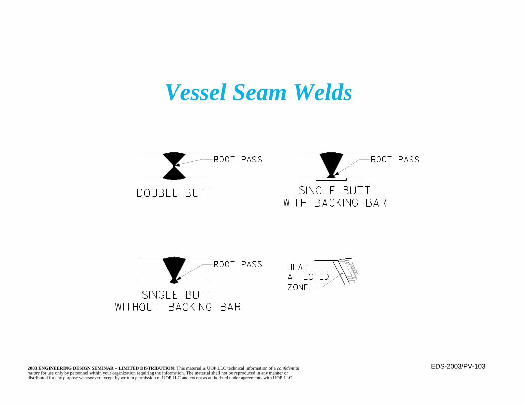
Vessel Seam Welds
EDS-2003/PV-1042003 ENGINEERING DESIGN SEMINAR – LIMITED DISTRIBUTION: This material is UOP LLC technical information of a confidentialnature for use only by personnel within your organization requiring the information. The material shall not be reproduced in any manner ordistributed for any purpose whatsoever except by written permission of UOP LLC and except as authorized under agreements with UOP LLC.
Welding Methods
n All processes use an arc between the electrodeand base metal to produce the heat for fusion
– Some electrodes become a part of the weld(consumable) while others do not (non-consumable)
n All processes are dependent upon a competentwelder, qualified per the governing code
n Procedures are written and welders tested foreach type of weld used.
n Low hydrogen is desired to prevent flaws andcracking, hence electrodes must be kept dry
EDS-2003/PV-1052003 ENGINEERING DESIGN SEMINAR – LIMITED DISTRIBUTION: This material is UOP LLC technical information of a confidentialnature for use only by personnel within your organization requiring the information. The material shall not be reproduced in any manner ordistributed for any purpose whatsoever except by written permission of UOP LLC and except as authorized under agreements with UOP LLC.
Welding Methods(continued)
n Shielded Metal Arc (SMAW)– Shielding of arc provided by gases from
electrode covering decomposition– Molten flux or slag provides more shielding– Electrode is consumed– Usually done manually– Can be done in any position– Good ductility and resistance to weld shrinkage
cracks
EDS-2003/PV-1062003 ENGINEERING DESIGN SEMINAR – LIMITED DISTRIBUTION: This material is UOP LLC technical information of a confidentialnature for use only by personnel within your organization requiring the information. The material shall not be reproduced in any manner ordistributed for any purpose whatsoever except by written permission of UOP LLC and except as authorized under agreements with UOP LLC.
Welding Methods(continued)
n Gas Metal Arc (GMAW)– Shielding is from a gas stream– Electrode is consumable and becomes filler
material– Usually done automatically (machine) with a
continuously fed electrode
EDS-2003/PV-1072003 ENGINEERING DESIGN SEMINAR – LIMITED DISTRIBUTION: This material is UOP LLC technical information of a confidentialnature for use only by personnel within your organization requiring the information. The material shall not be reproduced in any manner ordistributed for any purpose whatsoever except by written permission of UOP LLC and except as authorized under agreements with UOP LLC.
Welding Methods(continued)
n Gas Metal Arc (GMAW) (continued)– Can be done in any position with proper
shielding gas selection (e.g. argon is heavierthan air and is not used for overhead welding)
– Weld spatter is a concern– Sometimes known as MIG (Metal Inert Gas)– Use often limited due to concerns about
difficult to detect cold lap or lack of fusion

EDS-2003/PV-1082003 ENGINEERING DESIGN SEMINAR – LIMITED DISTRIBUTION: This material is UOP LLC technical information of a confidentialnature for use only by personnel within your organization requiring the information. The material shall not be reproduced in any manner ordistributed for any purpose whatsoever except by written permission of UOP LLC and except as authorized under agreements with UOP LLC.
Welding Methods(continued)
n Submerged Arc (SAW)– Shielding from a granular, fusible flux (fused
flux provides additional protection)– Arc cannot be seen, hence its “submerged”– Usually a continuous, automatic (machine)
process– No weld spatter, but shielding flux may not
stay in place if in other than a flat position– Flux is a material that prevents formation or
aids removal of oxides and other undesirablesubstances
EDS-2003/PV-1092003 ENGINEERING DESIGN SEMINAR – LIMITED DISTRIBUTION: This material is UOP LLC technical information of a confidentialnature for use only by personnel within your organization requiring the information. The material shall not be reproduced in any manner ordistributed for any purpose whatsoever except by written permission of UOP LLC and except as authorized under agreements with UOP LLC.
Welding Methods(continued)
n Gas Tungsten Arc (GTAW)– Shielding from a gas stream (typically argon)– Uses a non-consumable tungsten electrode– Filler metal may be added– Used for thin materials (< 3-4mm) in all positions– Usually manual but may be automatic– Also known as TIG (Tungsten Inert Gas)
EDS-2003/PV-1102003 ENGINEERING DESIGN SEMINAR – LIMITED DISTRIBUTION: This material is UOP LLC technical information of a confidentialnature for use only by personnel within your organization requiring the information. The material shall not be reproduced in any manner ordistributed for any purpose whatsoever except by written permission of UOP LLC and except as authorized under agreements with UOP LLC.
Welding Methods(continued)
n Flux Cored Arc (FCAW)– Shielding gas from decomposition of the
electrode and, occasionally, an external gas– Often produces a slag covering the weld
EDS-2003/PV-1112003 ENGINEERING DESIGN SEMINAR – LIMITED DISTRIBUTION: This material is UOP LLC technical information of a confidentialnature for use only by personnel within your organization requiring the information. The material shall not be reproduced in any manner ordistributed for any purpose whatsoever except by written permission of UOP LLC and except as authorized under agreements with UOP LLC.
Welding Methods(continued)
n Electric Resistance Welding– Heating of the base metal by resistance to an
electric current– Does not melt the metal– Narrow, sometimes hard to detect weld or
fusion line– Very limited applicability to pressure vessels
EDS-2003/PV-1122003 ENGINEERING DESIGN SEMINAR – LIMITED DISTRIBUTION: This material is UOP LLC technical information of a confidentialnature for use only by personnel within your organization requiring the information. The material shall not be reproduced in any manner ordistributed for any purpose whatsoever except by written permission of UOP LLC and except as authorized under agreements with UOP LLC.
Pressure Testing
n Pressure testing is required by the ASME Code
n Testing to be performed after all fabrication,welding, and heat treatment is completed
– Testing should occur prior to any painting orpriming
n Testing to be observed by the authorized inspector
EDS-2003/PV-1132003 ENGINEERING DESIGN SEMINAR – LIMITED DISTRIBUTION: This material is UOP LLC technical information of a confidentialnature for use only by personnel within your organization requiring the information. The material shall not be reproduced in any manner ordistributed for any purpose whatsoever except by written permission of UOP LLC and except as authorized under agreements with UOP LLC.
Pressure Testing(continued)
n Test pressure may be based upon either– the design pressure– MAWP of the full, corroded or uncorroded
thickness
n Two types of pressure are accepted:– Hydrostatic– Pneumatic
EDS-2003/PV-1142003 ENGINEERING DESIGN SEMINAR – LIMITED DISTRIBUTION: This material is UOP LLC technical information of a confidentialnature for use only by personnel within your organization requiring the information. The material shall not be reproduced in any manner ordistributed for any purpose whatsoever except by written permission of UOP LLC and except as authorized under agreements with UOP LLC.
Hydrostatic Pressure Testing
n Vessel is filled with water and pressured tothe required value
n Section VIII Division 1 minimum requiredtest pressure at all locations = 1.3 • DP • SC/SH
n Use the lowest SC/SH ration May be based upon design pressure or testing
of full (uncorroded) thickness of vesseln Recommended test temperature is 30°F over
MDMT– Temperature is of the metal, not the test fluid
EDS-2003/PV-1152003 ENGINEERING DESIGN SEMINAR – LIMITED DISTRIBUTION: This material is UOP LLC technical information of a confidentialnature for use only by personnel within your organization requiring the information. The material shall not be reproduced in any manner ordistributed for any purpose whatsoever except by written permission of UOP LLC and except as authorized under agreements with UOP LLC.
Hydrostatic Pressure Testing(continued)
n Check flanges and shell for overstress due to testpressure + hydrostatic head (especially significantfor tall columns)
– No area may be stressed to more than 90 percent ofthe material’s yield stress
n Test is safer due to incompressibility of water (orother fluid)
– Little energy is stored in the test fluid underpressure
n Easy to see and detect leaks; large water moleculemay not reveal some small openings
n May add a dye or luminescent material to see leaks
EDS-2003/PV-1162003 ENGINEERING DESIGN SEMINAR – LIMITED DISTRIBUTION: This material is UOP LLC technical information of a confidentialnature for use only by personnel within your organization requiring the information. The material shall not be reproduced in any manner ordistributed for any purpose whatsoever except by written permission of UOP LLC and except as authorized under agreements with UOP LLC.
Hydrostatic Pressure Testing(continued)
n Must vent properly during filling to insurecomplete filling (including voids in internals)
n Avoid overstressing or lifting internals duringfilling
n Supports (e.g. support skirt and structure)must be adequate for liquid full vessel (may bedifficult to provide in situ)
n Adequate supply of suitable water may bedifficult to obtain
– For example, where stainless steel is present,chlorides are limited to 50ppm

EDS-2003/PV-1172003 ENGINEERING DESIGN SEMINAR – LIMITED DISTRIBUTION: This material is UOP LLC technical information of a confidentialnature for use only by personnel within your organization requiring the information. The material shall not be reproduced in any manner ordistributed for any purpose whatsoever except by written permission of UOP LLC and except as authorized under agreements with UOP LLC.
Hydrostatic Pressure Testing(continued)
n Avoid damage (e.g. pulling a vacuum) duringdrainage; fully removing liquid and drying may bedifficult
– If not thoroughly dried, corrosion (rust) may occurn Some environments and internals (e.g. refractory)
may make hydrostatic testing undesirablen Water must not freeze
EDS-2003/PV-1182003 ENGINEERING DESIGN SEMINAR – LIMITED DISTRIBUTION: This material is UOP LLC technical information of a confidentialnature for use only by personnel within your organization requiring the information. The material shall not be reproduced in any manner ordistributed for any purpose whatsoever except by written permission of UOP LLC and except as authorized under agreements with UOP LLC.
Pneumatic Pressure Testing
n Test pressure is provided by compressing airor another gas
n Section VIII Division 1 minimum required testpressure at any point = 1.1 • DP • SC/SH
– As with hydrostatic testing, pressure may bebased upon the design pressure or the fullcorroded or uncorroded thickness
– Use the lowest SC/SH ration Metal test temperature must be at least 30°F
over the MDMT
EDS-2003/PV-1192003 ENGINEERING DESIGN SEMINAR – LIMITED DISTRIBUTION: This material is UOP LLC technical information of a confidentialnature for use only by personnel within your organization requiring the information. The material shall not be reproduced in any manner ordistributed for any purpose whatsoever except by written permission of UOP LLC and except as authorized under agreements with UOP LLC.
Pneumatic Pressure Testing(continued)
n Very dangerous due to stored energy in thecompressed gas
n Heat of compression, and subsequent cooling,may mean a loss of test pressure
n Existence of a leak may be detected by a loss of(i.e. difficulty maintaining) internal pressure
EDS-2003/PV-1202003 ENGINEERING DESIGN SEMINAR – LIMITED DISTRIBUTION: This material is UOP LLC technical information of a confidentialnature for use only by personnel within your organization requiring the information. The material shall not be reproduced in any manner ordistributed for any purpose whatsoever except by written permission of UOP LLC and except as authorized under agreements with UOP LLC.
Pneumatic Pressure Testing(continued)
n May be difficult to see leak location— coloredsmoke sometimes added
n No extra weight or hydrostatic pressure to considern Venting and concern with the filling method are
not a concern, nor is finding, draining, or disposingof the test medium
n Does not damage refractory or impact the process
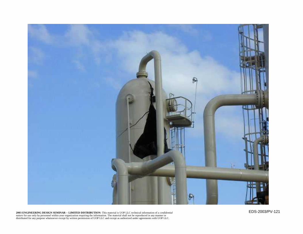
EDS-2003/PV-1212003 ENGINEERING DESIGN SEMINAR – LIMITED DISTRIBUTION: This material is UOP LLC technical information of a confidentialnature for use only by personnel within your organization requiring the information. The material shall not be reproduced in any manner ordistributed for any purpose whatsoever except by written permission of UOP LLC and except as authorized under agreements with UOP LLC.
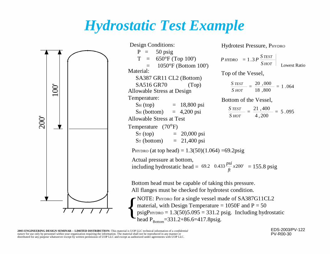
EDS-2003/PV-1222003 ENGINEERING DESIGN SEMINAR – LIMITED DISTRIBUTION: This material is UOP LLC technical information of a confidentialnature for use only by personnel within your organization requiring the information. The material shall not be reproduced in any manner ordistributed for any purpose whatsoever except by written permission of UOP LLC and except as authorized under agreements with UOP LLC.
Hydrostatic Test ExampleDesign Conditions:
P = 50 psigT = 650°F (Top 100') = 1050°F (Bottom 100')
200'
100'
Material:SA387 GR11 CL2 (Bottom)SA516 GR70 (Top)
PV-R00-30
Allowable Stress at DesignTemperature:
SH (top) = 18,800 psiSH (bottom) = 4,200 psi
Allowable Stress at TestTemperature (70°F)
ST (top) = 20,000 psiST (bottom) = 21,400 psi
Hydrotest Pressure, PHYDRO
HOT
TESTHYDRO
SSPP 3.1=
064.1800,18000,20 ==
HOT
TEST
SS
095.5200,4400,21 ==
HOT
TEST
SS
'200433.02.69 xft
psi+
Lowest Ratio
Top of the Vessel,
Bottom of the Vessel,
PHYDRO (at top head) = 1.3(50)(1.064) =69.2psig
Actual pressure at bottom,including hydrostatic head = = 155.8 psig
Bottom head must be capable of taking this pressure.All flanges must be checked for hydrotest condition.
NOTE: PHYDRO for a single vessel made of SA387G11CL2material, with Design Temperature = 1050F and P = 50psigPHYDRO = 1.3(50)5.095 = 331.2 psig. Including hydrostatichead PBottom=331.2+86.6=417.8psig.
{
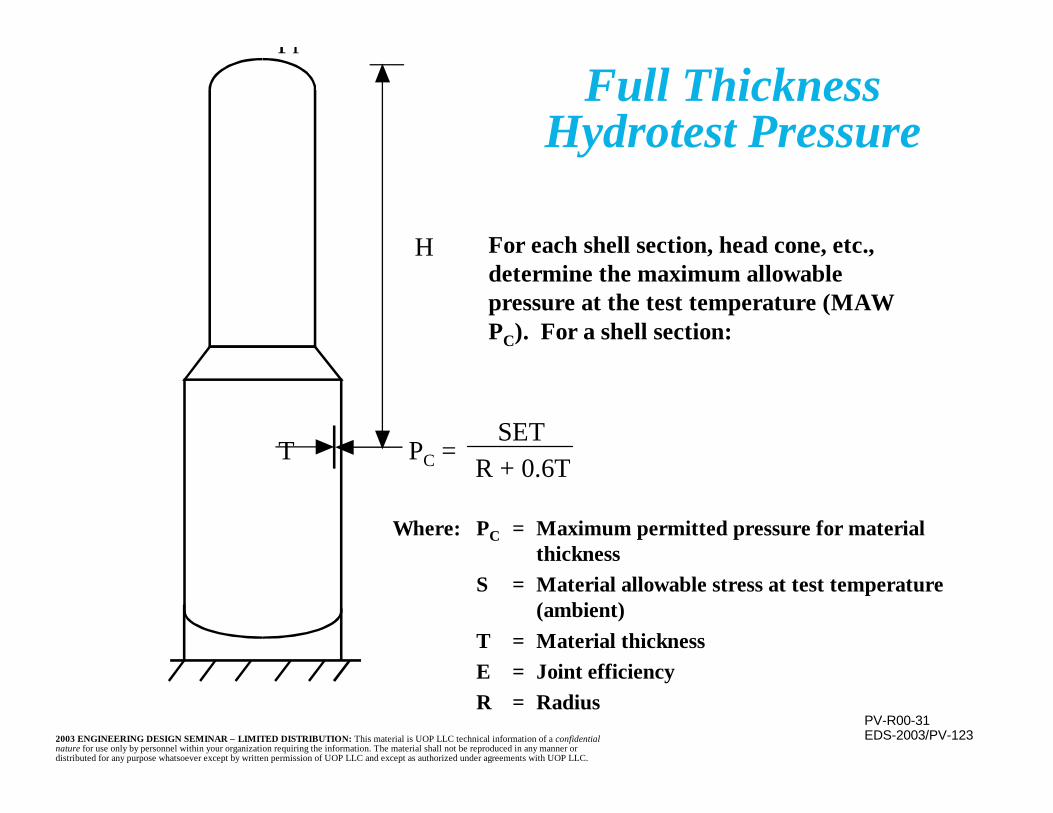
EDS-2003/PV-1232003 ENGINEERING DESIGN SEMINAR – LIMITED DISTRIBUTION: This material is UOP LLC technical information of a confidentialnature for use only by personnel within your organization requiring the information. The material shall not be reproduced in any manner ordistributed for any purpose whatsoever except by written permission of UOP LLC and except as authorized under agreements with UOP LLC.
Full ThicknessHydrotest Pressure
Pr
H
T PC =SET
R + 0.6T
PV-R00-31
For each shell section, head cone, etc.,determine the maximum allowablepressure at the test temperature (MAWPC). For a shell section:
Where: PC = Maximum permitted pressure for materialthickness
S = Material allowable stress at test temperature(ambient)
T = Material thicknessE = Joint efficiencyR = Radius
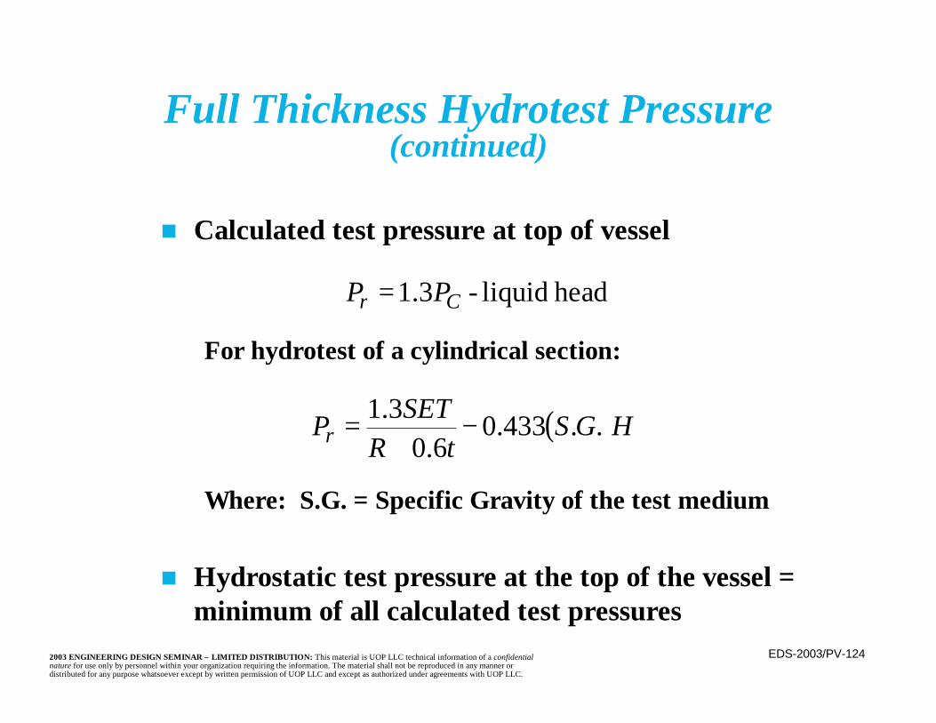
EDS-2003/PV-1242003 ENGINEERING DESIGN SEMINAR – LIMITED DISTRIBUTION: This material is UOP LLC technical information of a confidentialnature for use only by personnel within your organization requiring the information. The material shall not be reproduced in any manner ordistributed for any purpose whatsoever except by written permission of UOP LLC and except as authorized under agreements with UOP LLC.
n Calculated test pressure at top of vessel
For hydrotest of a cylindrical section:
Where: S.G. = Specific Gravity of the test medium
n Hydrostatic test pressure at the top of the vessel =minimum of all calculated test pressures
head liquid-3.1 Cr PP =
( )HGStR
SETPr ..433.06.0
3.1 −+
=
Full Thickness Hydrotest Pressure(continued)
EDS-2003/PV-1252003 ENGINEERING DESIGN SEMINAR – LIMITED DISTRIBUTION: This material is UOP LLC technical information of a confidentialnature for use only by personnel within your organization requiring the information. The material shall not be reproduced in any manner ordistributed for any purpose whatsoever except by written permission of UOP LLC and except as authorized under agreements with UOP LLC.
Vessel Supports
n Straight skirts below the vessel are mostcommon for vertical vessels
n Skirt is best centered on the shell thicknessn Skirt Details
– For vessels subjected to high (creep range)temperatures, cyclic loading, or with thickshells a contoured joint is used to reduce stressconcentrations
– Insulation details locate thermal gradients awayfrom the joint

EDS-2003/PV-1262003 ENGINEERING DESIGN SEMINAR – LIMITED DISTRIBUTION: This material is UOP LLC technical information of a confidentialnature for use only by personnel within your organization requiring the information. The material shall not be reproduced in any manner ordistributed for any purpose whatsoever except by written permission of UOP LLC and except as authorized under agreements with UOP LLC.
Vessel Supports(continued)
n Skirt Details (continued)– Other heavy wall or “severe” service equipment
uses a less stringent detail, usually a flat exteriorface with a weld height at least twice its width
– Remaining equipment uses a “standard” filletwelded joint
n Flared skirts (conical skirt attached to the sideof the vessel) are often used for equipmentsupported on a tabletop or a structure (e.g.,reactors with unloading space beneath them)
EDS-2003/PV-1272003 ENGINEERING DESIGN SEMINAR – LIMITED DISTRIBUTION: This material is UOP LLC technical information of a confidentialnature for use only by personnel within your organization requiring the information. The material shall not be reproduced in any manner ordistributed for any purpose whatsoever except by written permission of UOP LLC and except as authorized under agreements with UOP LLC.
Vessel Supports(continued)
n A flared skirt allows the vessel to project belowthe support level, reducing the wind overturningmoment on the vessel
n An alternative to a flared skirt is support fromlugs
– Tension and compression rings are required toavoid high local stresses
n Small vessels are occasionally supported by legs– This alternative should be considered only for
short, small diameter, lightly loaded items
EDS-2003/PV-1282003 ENGINEERING DESIGN SEMINAR – LIMITED DISTRIBUTION: This material is UOP LLC technical information of a confidentialnature for use only by personnel within your organization requiring the information. The material shall not be reproduced in any manner ordistributed for any purpose whatsoever except by written permission of UOP LLC and except as authorized under agreements with UOP LLC.
Vessel Supports(continued)
n Horizontal vessels are supported by saddleslocated near the ends
n Design of this system is fairly specialized inorder to avoid shell distortions at the saddlesand “sagging” of the vessel between saddles

EDS-2003/PV-1292003 ENGINEERING DESIGN SEMINAR – LIMITED DISTRIBUTION: This material is UOP LLC technical information of a confidentialnature for use only by personnel within your organization requiring the information. The material shall not be reproduced in any manner ordistributed for any purpose whatsoever except by written permission of UOP LLC and except as authorized under agreements with UOP LLC.
Vessel Support Skirts
n Vents are required at the top of the enclosedspace to allow escape of any gases and topromote air flow and cooling
n Flanges are not permitted beneath skirtsbecause they are a leak source and are noteasily accessible inside a skirt
– The confined space promotes dangerousconcentration of leaking vapors

EDS-2003/PV-1302003 ENGINEERING DESIGN SEMINAR – LIMITED DISTRIBUTION: This material is UOP LLC technical information of a confidentialnature for use only by personnel within your organization requiring the information. The material shall not be reproduced in any manner ordistributed for any purpose whatsoever except by written permission of UOP LLC and except as authorized under agreements with UOP LLC.
Vessel Support Skirts(continued)
n Skirt length must be sufficient to absorb anyradial thermal growth of the vessel
n Upper portion of skirts is made of the samematerial as the vessel shell
– Remainder of the uninsulated skirt may becarbon steel
n Provide a “hot box” at the skirt/shell junctionfor elevated temperature service
– This moves the thermal stresses away from themechanical stresses and HAZ at the junction
EDS-2003/PV-1312003 ENGINEERING DESIGN SEMINAR – LIMITED DISTRIBUTION: This material is UOP LLC technical information of a confidentialnature for use only by personnel within your organization requiring the information. The material shall not be reproduced in any manner ordistributed for any purpose whatsoever except by written permission of UOP LLC and except as authorized under agreements with UOP LLC.
n Joint between skirt and head shall have asmooth streamlined geometry
n Joint detail may be fabricated from:– A single forged component, butt welded as an
integral portion of the vessel– Weld metal buildup– Built up plate construction
n Backing strips, if used, shall be removed afterwelding
Contoured Support Skirt Detail

EDS-2003/PV-1322003 ENGINEERING DESIGN SEMINAR – LIMITED DISTRIBUTION: This material is UOP LLC technical information of a confidentialnature for use only by personnel within your organization requiring the information. The material shall not be reproduced in any manner ordistributed for any purpose whatsoever except by written permission of UOP LLC and except as authorized under agreements with UOP LLC.
Contoured Support Skirt Detail(continued)
n Welds shall be ground smooth and flush
n Weld surfaces shall be examined by magneticparticle or dye penetrant after final postweldheat treatment
n All pressure containing welds must be accessiblefor NDE in both the shop and the field
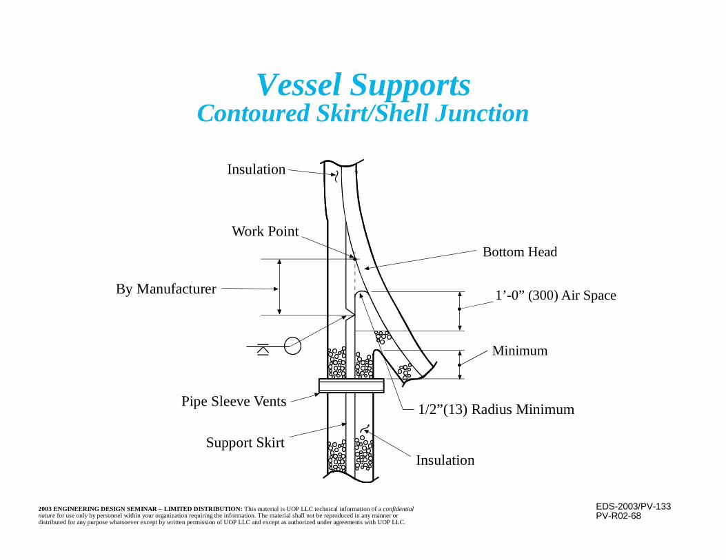
EDS-2003/PV-1332003 ENGINEERING DESIGN SEMINAR – LIMITED DISTRIBUTION: This material is UOP LLC technical information of a confidentialnature for use only by personnel within your organization requiring the information. The material shall not be reproduced in any manner ordistributed for any purpose whatsoever except by written permission of UOP LLC and except as authorized under agreements with UOP LLC.
Vessel SupportsContoured Skirt/Shell Junction
PV-R02-68
Bottom Head
Insulation
1’-0” (300) Air Space
Minimum
1/2”(13) Radius Minimum
InsulationSupport Skirt
Pipe Sleeve Vents
Work Point
By Manufacturer
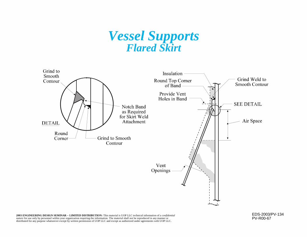
EDS-2003/PV-1342003 ENGINEERING DESIGN SEMINAR – LIMITED DISTRIBUTION: This material is UOP LLC technical information of a confidentialnature for use only by personnel within your organization requiring the information. The material shall not be reproduced in any manner ordistributed for any purpose whatsoever except by written permission of UOP LLC and except as authorized under agreements with UOP LLC.
Vessel SupportsFlared Skirt
PV-R00-67
EDS-2003/PV-1352003 ENGINEERING DESIGN SEMINAR – LIMITED DISTRIBUTION: This material is UOP LLC technical information of a confidentialnature for use only by personnel within your organization requiring the information. The material shall not be reproduced in any manner ordistributed for any purpose whatsoever except by written permission of UOP LLC and except as authorized under agreements with UOP LLC.
n Revamps include any re-evaluation and/ormodification of an existing vessel
– Rerates and evaluation for different operatingconditions is included
n Perform a complete engineering evaluation ofthe vessel for any new design conditions orimposed loads
n All modifications must be designed andperformed in accordance with the governingcodes including the inspection codes (NB-23 orAPI-510)
Revamps

EDS-2003/PV-1362003 ENGINEERING DESIGN SEMINAR – LIMITED DISTRIBUTION: This material is UOP LLC technical information of a confidentialnature for use only by personnel within your organization requiring the information. The material shall not be reproduced in any manner ordistributed for any purpose whatsoever except by written permission of UOP LLC and except as authorized under agreements with UOP LLC.
Revamps(continued)
n Consider a formal fitness for service evaluation,especially if the vessel operated in the creeprange, has been deformed, has significantcorrosion damage, experienced operationalupsets including overpressure or overheating,was subjected to cyclic loading or has beendamaged (e.g. cracks) or deformed (e.g. bulges).
n API 579 provides a basis for evaluation ofcracks and similar flaws, local thin areas(LTA’s), bulges, creep and fatigue damage, etc.
EDS-2003/PV-1372003 ENGINEERING DESIGN SEMINAR – LIMITED DISTRIBUTION: This material is UOP LLC technical information of a confidentialnature for use only by personnel within your organization requiring the information. The material shall not be reproduced in any manner ordistributed for any purpose whatsoever except by written permission of UOP LLC and except as authorized under agreements with UOP LLC.
Revamps(continued)
n Vessel must be thoroughly inspected, bothvisually and by nondestructive means, prior tocommencement of the evaluation and anymodifications.
n A complete metallurgical evaluation is alsonecessary to determine the presentmetallurgical condition after operation (e.g.,creep, fatigue, embrittlement, etc).
EDS-2003/PV-1382003 ENGINEERING DESIGN SEMINAR – LIMITED DISTRIBUTION: This material is UOP LLC technical information of a confidentialnature for use only by personnel within your organization requiring the information. The material shall not be reproduced in any manner ordistributed for any purpose whatsoever except by written permission of UOP LLC and except as authorized under agreements with UOP LLC.
Revamps(continued)
n Suitability for continued service under the sameor new service conditions must be determinedper the original code of construction.
n Very difficult to evaluate Division 2 vessels dueto the detailed analysis originally required.
n Consider evaluation in accordance with thecurrent design code to investigate the effect ofcode modifications (e.g. lower allowable stresses)since the original code.
EDS-2003/PV-1392003 ENGINEERING DESIGN SEMINAR – LIMITED DISTRIBUTION: This material is UOP LLC technical information of a confidentialnature for use only by personnel within your organization requiring the information. The material shall not be reproduced in any manner ordistributed for any purpose whatsoever except by written permission of UOP LLC and except as authorized under agreements with UOP LLC.
Revamps(continued)
n Suitability of the materials for the intendedatmosphere must be checked, even if it has notchanged
– For example, the Nelson curves for hydrogenatmospheres are occasionally revised so that amaterial may no longer be suitable foroperation at the intended design conditions
n Review flange classesn Review nozzle reinforcementn If the vessel is relocated, review wind and
earthquake
EDS-2003/PV-1402003 ENGINEERING DESIGN SEMINAR – LIMITED DISTRIBUTION: This material is UOP LLC technical information of a confidentialnature for use only by personnel within your organization requiring the information. The material shall not be reproduced in any manner ordistributed for any purpose whatsoever except by written permission of UOP LLC and except as authorized under agreements with UOP LLC.
Revamps(continued)
n For service in the creep range, a remaining lifeevaluation is necessary as a minimum
n Proper fabrication methods must be used forthe alteration, considering that the vessel hasbeen in service
– More care may be needed to prevent damage(e.g. maintenance of proper pre, during, andpost-weld heat temperatures, sequence ofwelding, dehydrogenization, existence of coke)
n Thoroughly inspect and possibly test themodifications

EDS-2003/PV-1412003 ENGINEERING DESIGN SEMINAR – LIMITED DISTRIBUTION: This material is UOP LLC technical information of a confidentialnature for use only by personnel within your organization requiring the information. The material shall not be reproduced in any manner ordistributed for any purpose whatsoever except by written permission of UOP LLC and except as authorized under agreements with UOP LLC.
FCC Revamp

EDS-2003/PV-1422003 ENGINEERING DESIGN SEMINAR – LIMITED DISTRIBUTION: This material is UOP LLC technical information of a confidentialnature for use only by personnel within your organization requiring the information. The material shall not be reproduced in any manner ordistributed for any purpose whatsoever except by written permission of UOP LLC and except as authorized under agreements with UOP LLC.
On-Stream Repair Concerns
n Welding to operating equipment is dangerous– Welding may add to stresses already present– This may over-stress material or propagate an
existing crackn Welding will increase the local metal
temperature, perhaps to the point the loadcarrying ability is compromised
n If there is a leak, welding arc may ignite vaporsn Hot taps are strongly discouraged
EDS-2003/PV-1432003 ENGINEERING DESIGN SEMINAR – LIMITED DISTRIBUTION: This material is UOP LLC technical information of a confidentialnature for use only by personnel within your organization requiring the information. The material shall not be reproduced in any manner ordistributed for any purpose whatsoever except by written permission of UOP LLC and except as authorized under agreements with UOP LLC.
On-Stream Repair Concerns(continued)
n Working in the presence of a process leak isvery dangerous
n Must avoid creating thermal stresses duringrepair procedure or shutdown
– Any patch must be the same material at thesame temperature as the base material at thetime of the repair
n Stress relief may be requiredn May need to vent beneath a patch to allow
escape of welding gases
EDS-2003/PV-1442003 ENGINEERING DESIGN SEMINAR – LIMITED DISTRIBUTION: This material is UOP LLC technical information of a confidentialnature for use only by personnel within your organization requiring the information. The material shall not be reproduced in any manner ordistributed for any purpose whatsoever except by written permission of UOP LLC and except as authorized under agreements with UOP LLC.
Stress Analysis
n Terminologyn Primary Membrane Stresses in Shellsn Primary Membrane Stresses in Headsn Code Design Equations for Shells and Headsn Nozzle Reinforcementn Discontinuity Stressesn Code Allowable Stress Basisn Wind and Earthquake

EDS-2003/PV-1452003 ENGINEERING DESIGN SEMINAR – LIMITED DISTRIBUTION: This material is UOP LLC technical information of a confidentialnature for use only by personnel within your organization requiring the information. The material shall not be reproduced in any manner ordistributed for any purpose whatsoever except by written permission of UOP LLC and except as authorized under agreements with UOP LLC.
Stress and Strain Definitions
n Strain - Distortion per unit length. For a tensiletest it’s usually the elongation divided by theoriginal stressed length. It may be applieddirectly or be the byproduct of an appliedstress.
n Stress - Force divided by the area over which itis applied. For a tensile test the area is theoriginal cross section. It may be applied directlyof be the byproduct of an applied strain.
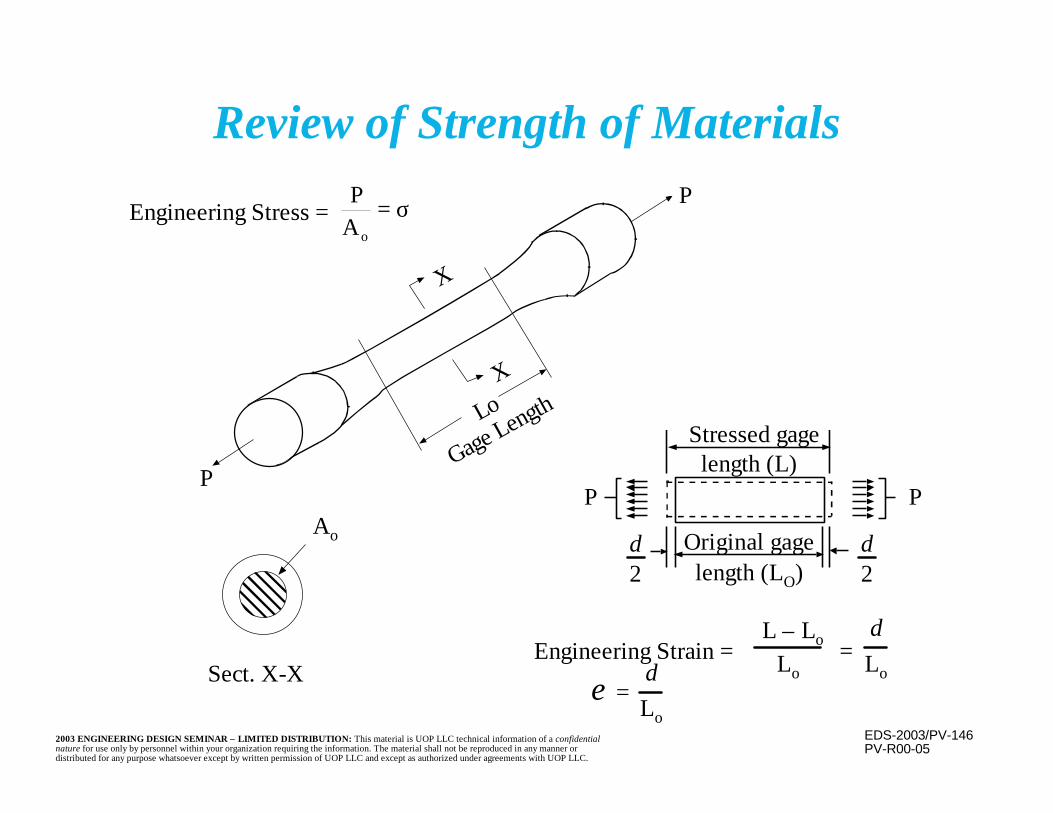
EDS-2003/PV-1462003 ENGINEERING DESIGN SEMINAR – LIMITED DISTRIBUTION: This material is UOP LLC technical information of a confidentialnature for use only by personnel within your organization requiring the information. The material shall not be reproduced in any manner ordistributed for any purpose whatsoever except by written permission of UOP LLC and except as authorized under agreements with UOP LLC.
Review of Strength of Materials
PV-R00-05
Stressed gagelength (L)
Original gagelength (LO)
P P
Sect. X-X
Gage Length
X
X
P
P
Engineering Stress =
Engineering Strain =
δ2
δ2
L – Lo =δ
Lo LoδLo
=
Lo
Ao
ε
PA o
= σ

EDS-2003/PV-1472003 ENGINEERING DESIGN SEMINAR – LIMITED DISTRIBUTION: This material is UOP LLC technical information of a confidentialnature for use only by personnel within your organization requiring the information. The material shall not be reproduced in any manner ordistributed for any purpose whatsoever except by written permission of UOP LLC and except as authorized under agreements with UOP LLC.
Typical Stress-Strain Curvefor a Stainless Steel
PV-R01-71
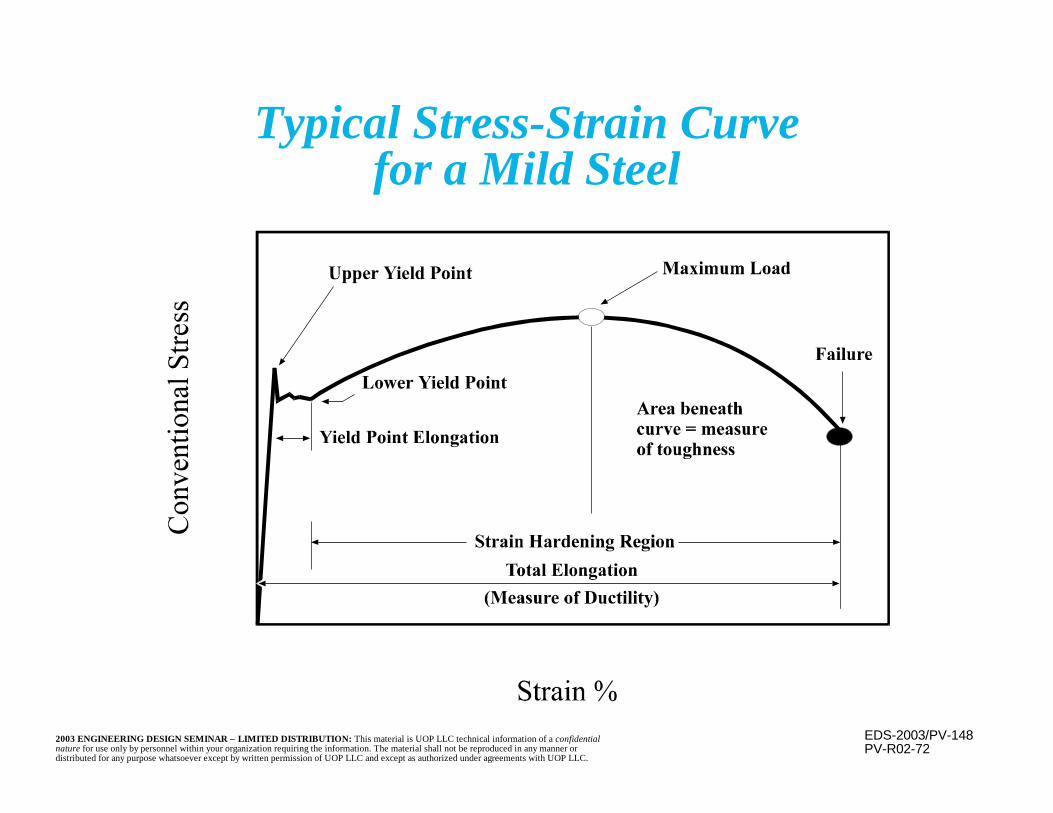
EDS-2003/PV-1482003 ENGINEERING DESIGN SEMINAR – LIMITED DISTRIBUTION: This material is UOP LLC technical information of a confidentialnature for use only by personnel within your organization requiring the information. The material shall not be reproduced in any manner ordistributed for any purpose whatsoever except by written permission of UOP LLC and except as authorized under agreements with UOP LLC.
Typical Stress-Strain Curvefor a Mild Steel
PV-R02-72

EDS-2003/PV-1492003 ENGINEERING DESIGN SEMINAR – LIMITED DISTRIBUTION: This material is UOP LLC technical information of a confidentialnature for use only by personnel within your organization requiring the information. The material shall not be reproduced in any manner ordistributed for any purpose whatsoever except by written permission of UOP LLC and except as authorized under agreements with UOP LLC.
Stress - Strain Terms
n Creep - Continuous change in strain over timeat elevated temperature under constant load ordisplacement conditions.
n Creep Strain - Increase in strain with timeunder constant loading conditions.
n Creep Relaxation - Reduction in hot stress withtime under constant displacement conditions.
n Creep Rupture - Failure due to excessiveaccumulated creep strain.

EDS-2003/PV-1502003 ENGINEERING DESIGN SEMINAR – LIMITED DISTRIBUTION: This material is UOP LLC technical information of a confidentialnature for use only by personnel within your organization requiring the information. The material shall not be reproduced in any manner ordistributed for any purpose whatsoever except by written permission of UOP LLC and except as authorized under agreements with UOP LLC.
Histories from a Loading AtLow Temperature
PV-R00-58
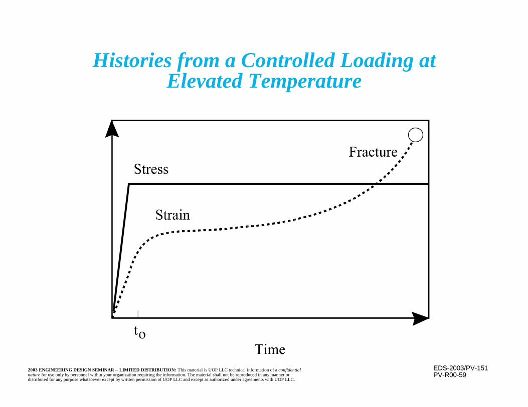
EDS-2003/PV-1512003 ENGINEERING DESIGN SEMINAR – LIMITED DISTRIBUTION: This material is UOP LLC technical information of a confidentialnature for use only by personnel within your organization requiring the information. The material shall not be reproduced in any manner ordistributed for any purpose whatsoever except by written permission of UOP LLC and except as authorized under agreements with UOP LLC.
Histories from a Controlled Loading atElevated Temperature
PV-R00-59
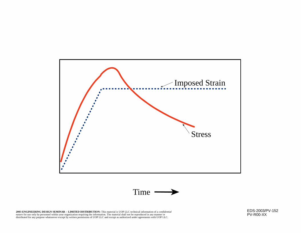
EDS-2003/PV-1522003 ENGINEERING DESIGN SEMINAR – LIMITED DISTRIBUTION: This material is UOP LLC technical information of a confidentialnature for use only by personnel within your organization requiring the information. The material shall not be reproduced in any manner ordistributed for any purpose whatsoever except by written permission of UOP LLC and except as authorized under agreements with UOP LLC.
Stress
Time
Imposed Strain
PV-R00-XX
EDS-2003/PV-1532003 ENGINEERING DESIGN SEMINAR – LIMITED DISTRIBUTION: This material is UOP LLC technical information of a confidentialnature for use only by personnel within your organization requiring the information. The material shall not be reproduced in any manner ordistributed for any purpose whatsoever except by written permission of UOP LLC and except as authorized under agreements with UOP LLC.
Stress - Strain Terms
n Ductility - Ability to distort plastically beforefracturing
– Measured by elongation or area reduction in atensile test.
– Ductile material will distort dramatically beforefracturing, giving warning of an overload.
– Brittle material will distort very little beforefracturing, giving little or no warning.
– As temperature is lowered, ductile material canbecome brittle. This point is the transitiontemperature.

EDS-2003/PV-1542003 ENGINEERING DESIGN SEMINAR – LIMITED DISTRIBUTION: This material is UOP LLC technical information of a confidentialnature for use only by personnel within your organization requiring the information. The material shall not be reproduced in any manner ordistributed for any purpose whatsoever except by written permission of UOP LLC and except as authorized under agreements with UOP LLC.
Stress - Strain Terms(continued)
n Elasticity - Ability of a solid to deform in directproportion to, and in phase with, increases ordecreases in applied force, i.e., stress and strainare proportional
n Elastic Distortion - Strain is fully recoveredwhen the stress is removed
n Plasticity - Ability of a material to deforminelastically without rupture
n Plastic (Inelastic) Distortion - Strain is notproportional to stress and is not recoveredwhen the stress is removed, i.e. it is permanent
EDS-2003/PV-1552003 ENGINEERING DESIGN SEMINAR – LIMITED DISTRIBUTION: This material is UOP LLC technical information of a confidentialnature for use only by personnel within your organization requiring the information. The material shall not be reproduced in any manner ordistributed for any purpose whatsoever except by written permission of UOP LLC and except as authorized under agreements with UOP LLC.
Stress - Strain Terms(continued)
n Modulus of Elasticity (Young’s Modulus) -Ratio of stress to strain before theproportional limit, e.g., the slope of the curve
n Proportional Limit - Stress at which stressand strain cease to be directly proportional(i.e., a straight line relationship)

EDS-2003/PV-1562003 ENGINEERING DESIGN SEMINAR – LIMITED DISTRIBUTION: This material is UOP LLC technical information of a confidentialnature for use only by personnel within your organization requiring the information. The material shall not be reproduced in any manner ordistributed for any purpose whatsoever except by written permission of UOP LLC and except as authorized under agreements with UOP LLC.
Stress - Strain Terms(continued)
n Strain Hardening - Increase in stresscapacity due to internal strain redistributionin ductile materials
n Stress Rupture - Time dependent failure– Rupture is a function of time, temperature,
and stress
EDS-2003/PV-1572003 ENGINEERING DESIGN SEMINAR – LIMITED DISTRIBUTION: This material is UOP LLC technical information of a confidentialnature for use only by personnel within your organization requiring the information. The material shall not be reproduced in any manner ordistributed for any purpose whatsoever except by written permission of UOP LLC and except as authorized under agreements with UOP LLC.
Stress - Strain Terms(continued)
n Toughness - Ability to absorb energy– Generally characterized by the area beneath the
stress-strain curve– A common test method is the Chary V-notch
impact test
n Ultimate Strength - Maximum stress, basedupon the original area, before failure
EDS-2003/PV-1582003 ENGINEERING DESIGN SEMINAR – LIMITED DISTRIBUTION: This material is UOP LLC technical information of a confidentialnature for use only by personnel within your organization requiring the information. The material shall not be reproduced in any manner ordistributed for any purpose whatsoever except by written permission of UOP LLC and except as authorized under agreements with UOP LLC.
Stress - Strain Terms(continued)
n Yield Strength - Stress at which a small additionalstress increase results in a large additional strain
– Same as the proportional limit if there is a clearbreak between the elastic and inelastic portions ofthe stress-strain curve
– If there is not a clear break between the elastic andinelastic portions of the curve it’s defined as thestress at which a line beginning at 0.2% (0.002)strain and drawn parallel to the elastic portion ofthe curve intersects the stress-strain curve
EDS-2003/PV-1592003 ENGINEERING DESIGN SEMINAR – LIMITED DISTRIBUTION: This material is UOP LLC technical information of a confidentialnature for use only by personnel within your organization requiring the information. The material shall not be reproduced in any manner ordistributed for any purpose whatsoever except by written permission of UOP LLC and except as authorized under agreements with UOP LLC.
Stress Analysis of Pressure Vessels
n Basic Formulas for Stress
n ASME Code Pressure Design Equations
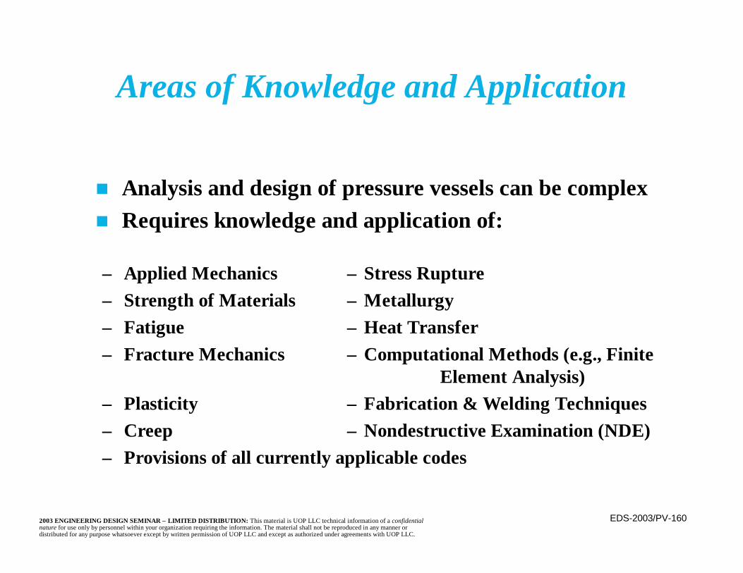
EDS-2003/PV-1602003 ENGINEERING DESIGN SEMINAR – LIMITED DISTRIBUTION: This material is UOP LLC technical information of a confidentialnature for use only by personnel within your organization requiring the information. The material shall not be reproduced in any manner ordistributed for any purpose whatsoever except by written permission of UOP LLC and except as authorized under agreements with UOP LLC.
Areas of Knowledge and Application
n Analysis and design of pressure vessels can be complexn Requires knowledge and application of:
– Applied Mechanics – Stress Rupture– Strength of Materials – Metallurgy– Fatigue – Heat Transfer– Fracture Mechanics – Computational Methods (e.g., Finite
Element Analysis)– Plasticity – Fabrication & Welding Techniques– Creep – Nondestructive Examination (NDE)– Provisions of all currently applicable codes
EDS-2003/PV-1612003 ENGINEERING DESIGN SEMINAR – LIMITED DISTRIBUTION: This material is UOP LLC technical information of a confidentialnature for use only by personnel within your organization requiring the information. The material shall not be reproduced in any manner ordistributed for any purpose whatsoever except by written permission of UOP LLC and except as authorized under agreements with UOP LLC.
n Primary Stress– Caused by an applied force, strain is a
response, i.e., a secondary event– If excessive, can cause failure in a single
application– Necessary to satisfy equilibrium of forces and
moments– Not self-limiting– Internal or external pressure– Weight, wind, earthquake
Stress Analysis of Pressure VesselsTypes of Stress

EDS-2003/PV-1622003 ENGINEERING DESIGN SEMINAR – LIMITED DISTRIBUTION: This material is UOP LLC technical information of a confidentialnature for use only by personnel within your organization requiring the information. The material shall not be reproduced in any manner ordistributed for any purpose whatsoever except by written permission of UOP LLC and except as authorized under agreements with UOP LLC.
Stress Analysis of Pressure VesselsTypes of Stress (continued)
n Secondary Stress– Caused by an applied strain, stress is a response,
i.e., a secondary event– Generally does not lead to failure in a single cycle– Self-limiting (e.g. thermal stress)– Local geometric effects, thermal stress, residual
stresses from welding (often due to constraints)
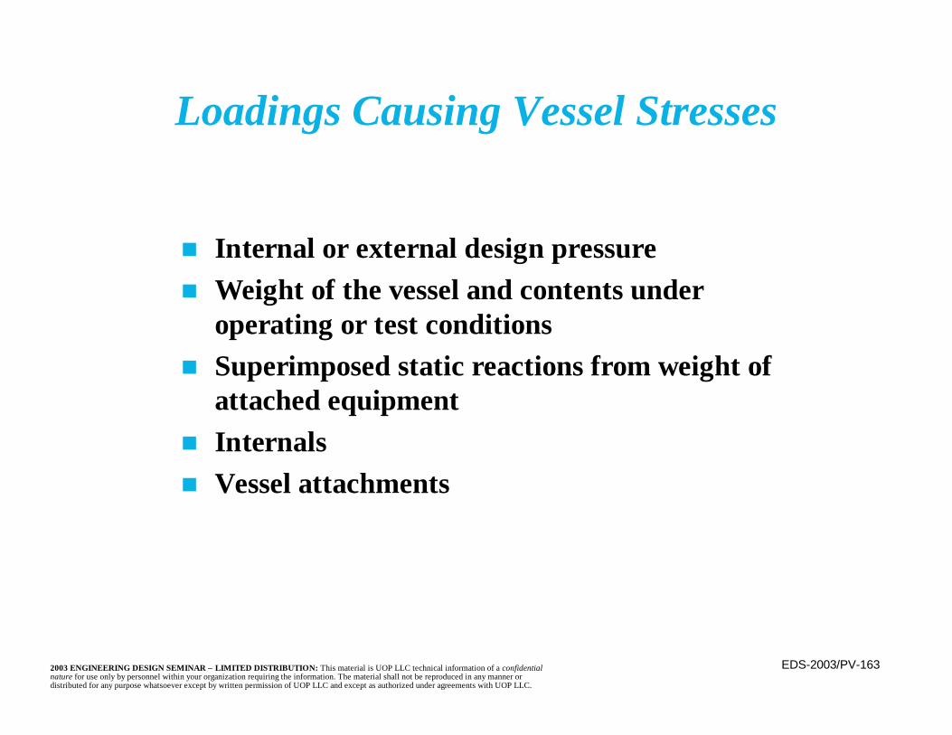
EDS-2003/PV-1632003 ENGINEERING DESIGN SEMINAR – LIMITED DISTRIBUTION: This material is UOP LLC technical information of a confidentialnature for use only by personnel within your organization requiring the information. The material shall not be reproduced in any manner ordistributed for any purpose whatsoever except by written permission of UOP LLC and except as authorized under agreements with UOP LLC.
n Internal or external design pressuren Weight of the vessel and contents under
operating or test conditionsn Superimposed static reactions from weight of
attached equipmentn Internalsn Vessel attachments
Loadings Causing Vessel Stresses
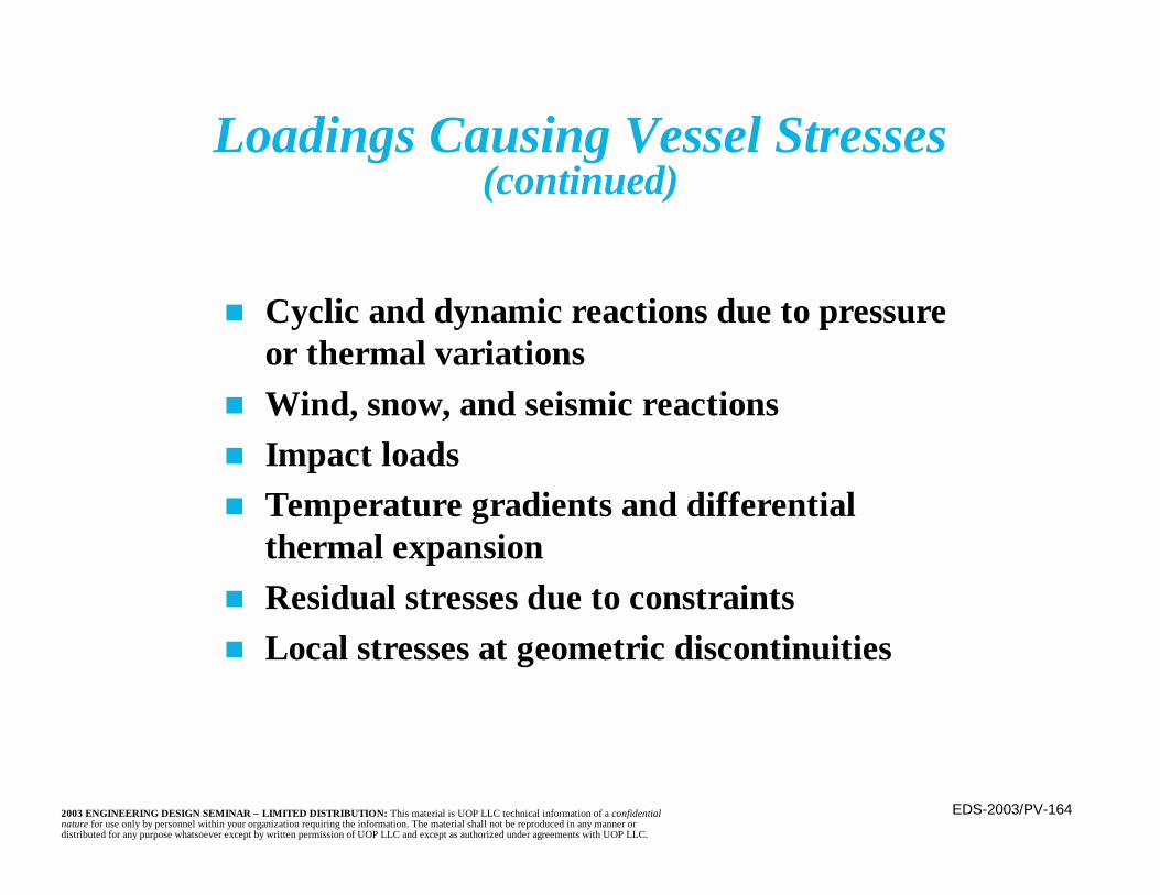
EDS-2003/PV-1642003 ENGINEERING DESIGN SEMINAR – LIMITED DISTRIBUTION: This material is UOP LLC technical information of a confidentialnature for use only by personnel within your organization requiring the information. The material shall not be reproduced in any manner ordistributed for any purpose whatsoever except by written permission of UOP LLC and except as authorized under agreements with UOP LLC.
n Cyclic and dynamic reactions due to pressureor thermal variations
n Wind, snow, and seismic reactionsn Impact loadsn Temperature gradients and differential
thermal expansionn Residual stresses due to constraintsn Local stresses at geometric discontinuities
Loadings Causing Vessel Stresses(continued)

EDS-2003/PV-1652003 ENGINEERING DESIGN SEMINAR – LIMITED DISTRIBUTION: This material is UOP LLC technical information of a confidentialnature for use only by personnel within your organization requiring the information. The material shall not be reproduced in any manner ordistributed for any purpose whatsoever except by written permission of UOP LLC and except as authorized under agreements with UOP LLC.
n Stress Types– Membrane Stress
• An essentially uniform stress averagedacross the thickness of the cross-section
– Bending Stress• Stress level varies through the thickness of
the cross-sectionn Stress Direction
– Circumferential– Longitudinal
Stress Analysis of Pressure VesselsTerminology
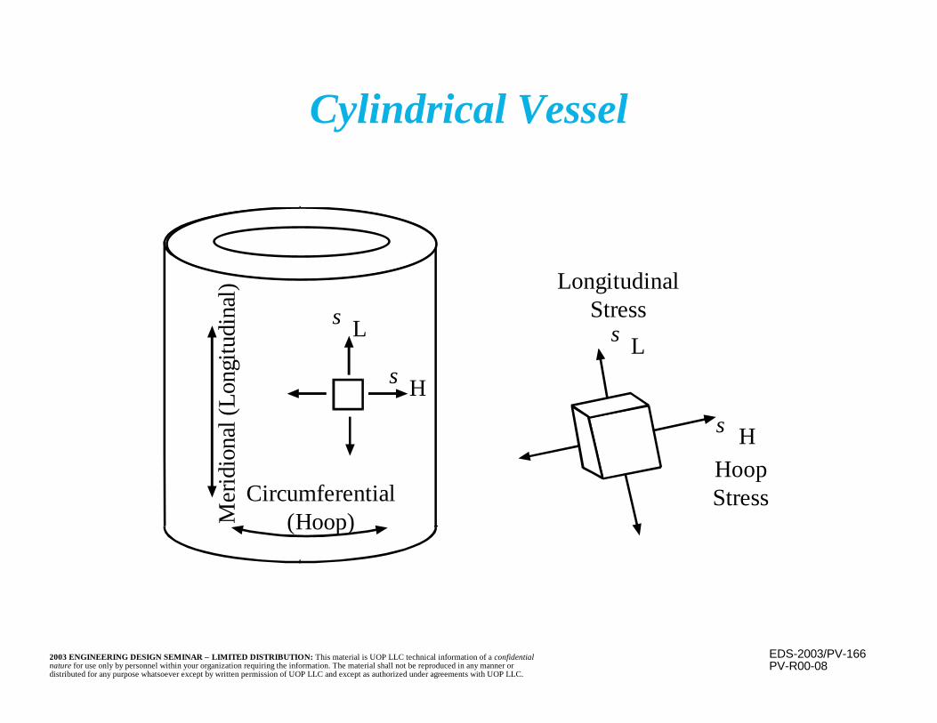
EDS-2003/PV-1662003 ENGINEERING DESIGN SEMINAR – LIMITED DISTRIBUTION: This material is UOP LLC technical information of a confidentialnature for use only by personnel within your organization requiring the information. The material shall not be reproduced in any manner ordistributed for any purpose whatsoever except by written permission of UOP LLC and except as authorized under agreements with UOP LLC.
Cylindrical Vessel
σ H
σ L
Circumferential(Hoop)M
erid
iona
l (Lo
ngitu
dina
l)
PV-R00-08
LongitudinalStress
σ L
σ HHoopStress
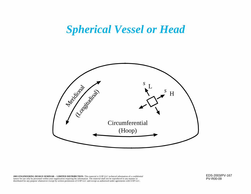
EDS-2003/PV-1672003 ENGINEERING DESIGN SEMINAR – LIMITED DISTRIBUTION: This material is UOP LLC technical information of a confidentialnature for use only by personnel within your organization requiring the information. The material shall not be reproduced in any manner ordistributed for any purpose whatsoever except by written permission of UOP LLC and except as authorized under agreements with UOP LLC.
Spherical Vessel or Head
σ H
σ L
PV-R00-09
Circumferential(Hoop)
(Lon
gitud
inal)
Meri
diona
l

EDS-2003/PV-1682003 ENGINEERING DESIGN SEMINAR – LIMITED DISTRIBUTION: This material is UOP LLC technical information of a confidentialnature for use only by personnel within your organization requiring the information. The material shall not be reproduced in any manner ordistributed for any purpose whatsoever except by written permission of UOP LLC and except as authorized under agreements with UOP LLC.
PV-R00-10
Sectional view of a pressure vesselcylinder or sphere
L = Length ofcylinder
Hoop stressσ H
R
Pressure
P
t
CL
Applied force= Pressure x fluid areaReaction force = Stress x metal area
a. Cylinder:Metal area = 2[tL]Pressure area = 2 R L
Equilibrium,
b. Sphere:Metal Area = 2πRtPressure area = πR2
( )[ ] [ ]
tPR
RLPtL
H
H
=
=
σ
σ 22
[ ] [ ]σ π πσ
H
H
Rt P RpR
t
2
2
2==
Hoop Stress

EDS-2003/PV-1692003 ENGINEERING DESIGN SEMINAR – LIMITED DISTRIBUTION: This material is UOP LLC technical information of a confidentialnature for use only by personnel within your organization requiring the information. The material shall not be reproduced in any manner ordistributed for any purpose whatsoever except by written permission of UOP LLC and except as authorized under agreements with UOP LLC.
PV-R00-11
Longitudinal Stress
σ LLongitudinal stress
t, ThicknessR
( ) ( )σ π π
σL
L
Rt P RPR
t
2
2
2=
=
P

EDS-2003/PV-1702003 ENGINEERING DESIGN SEMINAR – LIMITED DISTRIBUTION: This material is UOP LLC technical information of a confidentialnature for use only by personnel within your organization requiring the information. The material shall not be reproduced in any manner ordistributed for any purpose whatsoever except by written permission of UOP LLC and except as authorized under agreements with UOP LLC.
Stresses in Pressure Vessels Due toInternal Pressure
ComponentHoop (Circumferential)
StressLongitudinal (Meridional)
Stress
Cylindrical ShelltRP
t2RP
Spherical Shell orHemispherical Head t2
RPt2RP
2:1 Elliptical Head:
At Center of Crown
At Knuckle
tRP
tRP−
tRP
t2RP
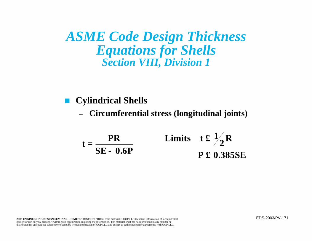
EDS-2003/PV-1712003 ENGINEERING DESIGN SEMINAR – LIMITED DISTRIBUTION: This material is UOP LLC technical information of a confidentialnature for use only by personnel within your organization requiring the information. The material shall not be reproduced in any manner ordistributed for any purpose whatsoever except by written permission of UOP LLC and except as authorized under agreements with UOP LLC.
ASME Code Design ThicknessEquations for Shells
Section VIII, Division 1
n Cylindrical Shells– Circumferential stress (longitudinal joints)
t PRSE P
=− 0 6.
Limits Rt 12
P 0.385SE
≤≤
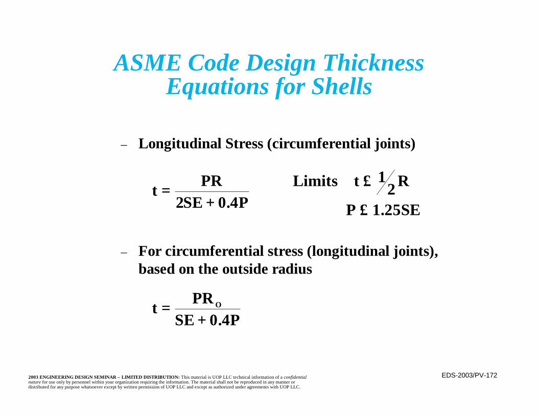
EDS-2003/PV-1722003 ENGINEERING DESIGN SEMINAR – LIMITED DISTRIBUTION: This material is UOP LLC technical information of a confidentialnature for use only by personnel within your organization requiring the information. The material shall not be reproduced in any manner ordistributed for any purpose whatsoever except by written permission of UOP LLC and except as authorized under agreements with UOP LLC.
ASME Code Design ThicknessEquations for Shells
– Longitudinal Stress (circumferential joints)
– For circumferential stress (longitudinal joints),based on the outside radius
t PRSE P
=+2 0 4.
Limits Rt 12
P 1.25SE
≤≤
t PRSE P
O=+ 0 4.

EDS-2003/PV-1732003 ENGINEERING DESIGN SEMINAR – LIMITED DISTRIBUTION: This material is UOP LLC technical information of a confidentialnature for use only by personnel within your organization requiring the information. The material shall not be reproduced in any manner ordistributed for any purpose whatsoever except by written permission of UOP LLC and except as authorized under agreements with UOP LLC.
ASME Code Design ThicknessEquations for Shells
n Spherical Shells
n Spherical shells based upon the outside radius
t PRSE P
=−2 0 2.
Limits t 0.356R P 0.665SE
≤≤
t PRSE P
O=+2 0 8.

EDS-2003/PV-1742003 ENGINEERING DESIGN SEMINAR – LIMITED DISTRIBUTION: This material is UOP LLC technical information of a confidentialnature for use only by personnel within your organization requiring the information. The material shall not be reproduced in any manner ordistributed for any purpose whatsoever except by written permission of UOP LLC and except as authorized under agreements with UOP LLC.
Pressure Vessel Heads
PV-R00-22
tn Pressure Vessel Heads
Ellipsoidal
where
For a 2:1 ellipsoidal head K=1
t PDKSE P
=−2 0 2.
or P = 2SEtKD + 0.2t
K Dh
= +
16
22
2
h
D
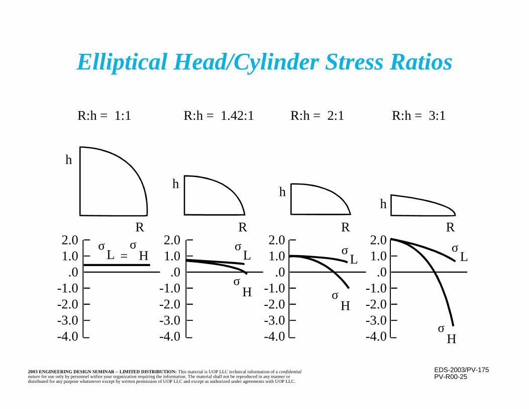
EDS-2003/PV-1752003 ENGINEERING DESIGN SEMINAR – LIMITED DISTRIBUTION: This material is UOP LLC technical information of a confidentialnature for use only by personnel within your organization requiring the information. The material shall not be reproduced in any manner ordistributed for any purpose whatsoever except by written permission of UOP LLC and except as authorized under agreements with UOP LLC.
Elliptical Head/Cylinder Stress Ratios
PV-R00-25
R:h = 1:1 R:h = 1.42:1 R:h = 2:1 R:h = 3:1
h
R
h
R
h
R
h
R2.01.0
.0-1.0-2.0-3.0-4.0
2.01.0
.0-1.0-2.0-3.0-4.0
2.01.0
.0-1.0-2.0-3.0-4.0
2.01.0
.0-1.0-2.0-3.0-4.0
σL
σH
σH σ
H
σH
σL
σL
σL =
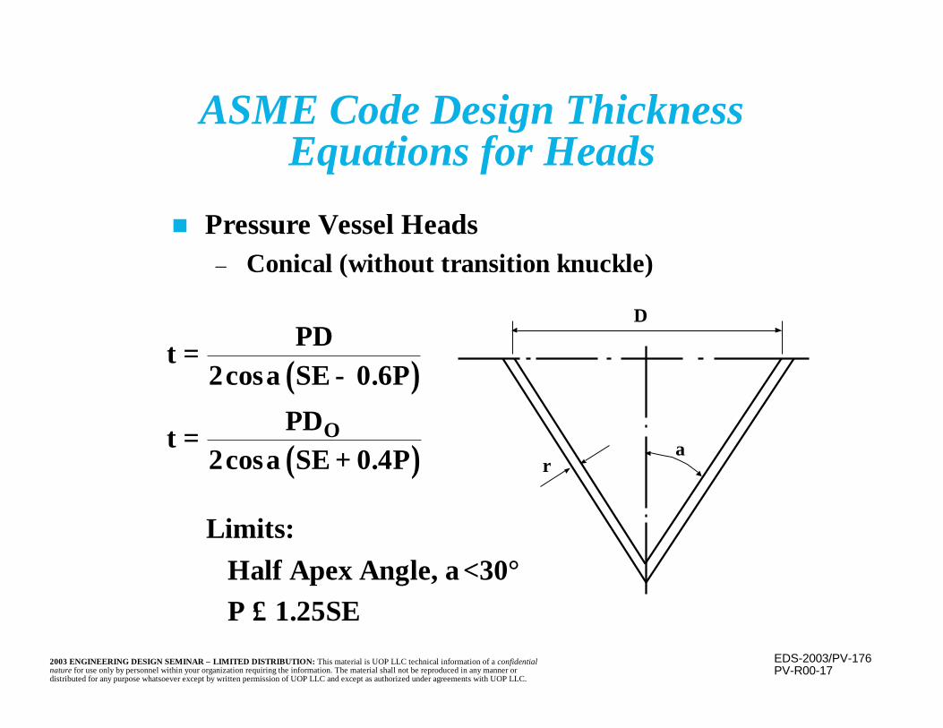
EDS-2003/PV-1762003 ENGINEERING DESIGN SEMINAR – LIMITED DISTRIBUTION: This material is UOP LLC technical information of a confidentialnature for use only by personnel within your organization requiring the information. The material shall not be reproduced in any manner ordistributed for any purpose whatsoever except by written permission of UOP LLC and except as authorized under agreements with UOP LLC.
ASME Code Design ThicknessEquations for Heads
n Pressure Vessel Heads– Conical (without transition knuckle)
( )
( )
t PDSE P
t PDSE P
O
=−
=+
2 0 6
2 0 4
cos .
cos .
α
α
Limits: Half Apex Angle, α<30° P ≤ 1.25SE
D
rα
PV-R00-17
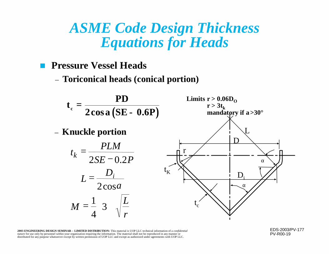
EDS-2003/PV-1772003 ENGINEERING DESIGN SEMINAR – LIMITED DISTRIBUTION: This material is UOP LLC technical information of a confidentialnature for use only by personnel within your organization requiring the information. The material shall not be reproduced in any manner ordistributed for any purpose whatsoever except by written permission of UOP LLC and except as authorized under agreements with UOP LLC.
ASME Code Design ThicknessEquations for Heads
n Pressure Vessel Heads– Toriconical heads (conical portion)
( )t PDSE Pc =
−2 0 6cos .αLimits r > 0.06DO
r > 3tkmandatory if α>30°
+=
=
−=
rLM
DiL
PSEPLMtk
341
cos2
2.02
α
PV-R00-19
DL
Di
r
tK
tc
α
α
– Knuckle portion

EDS-2003/PV-1782003 ENGINEERING DESIGN SEMINAR – LIMITED DISTRIBUTION: This material is UOP LLC technical information of a confidentialnature for use only by personnel within your organization requiring the information. The material shall not be reproduced in any manner ordistributed for any purpose whatsoever except by written permission of UOP LLC and except as authorized under agreements with UOP LLC.
Pressure Vessel Heads
n Pressure Vessel HeadsTorispherical
where
PV-R00-23
t PLMSE P
=−2 0 2.
or P = 2SEtLM + 0.2t
M Lr
= +
14
3 for the typical case where
r=0.06L and L=skirt OD,
t PLSE P
=−
0 8850 1
..
LD
r
t
EDS-2003/PV-1792003 ENGINEERING DESIGN SEMINAR – LIMITED DISTRIBUTION: This material is UOP LLC technical information of a confidentialnature for use only by personnel within your organization requiring the information. The material shall not be reproduced in any manner ordistributed for any purpose whatsoever except by written permission of UOP LLC and except as authorized under agreements with UOP LLC.
Symbols
t = Minimum required thickness, exclusive of corrosionallowance
tc = Minimum required thickness of cone, exclusive ofcorrosion allowance
tR = Minimum required thickness of knuckle, exclusive ofcorrosion allowance
P = Internal design pressureS = Tensile allowable stress value at design temperatureE = Joint efficiencyR = Inside radiusRO = Outside radius
EDS-2003/PV-1802003 ENGINEERING DESIGN SEMINAR – LIMITED DISTRIBUTION: This material is UOP LLC technical information of a confidentialnature for use only by personnel within your organization requiring the information. The material shall not be reproduced in any manner ordistributed for any purpose whatsoever except by written permission of UOP LLC and except as authorized under agreements with UOP LLC.
Symbols(continued)
D = Inside diameterDO = Outside diameterDL = Inside diameter of conical portion of
toriconical head = D-2r(1-cosα)α = One half apex angle of coner = Inside knuckle radiusL = Inside crown radiush = Minor axis of elliptical head
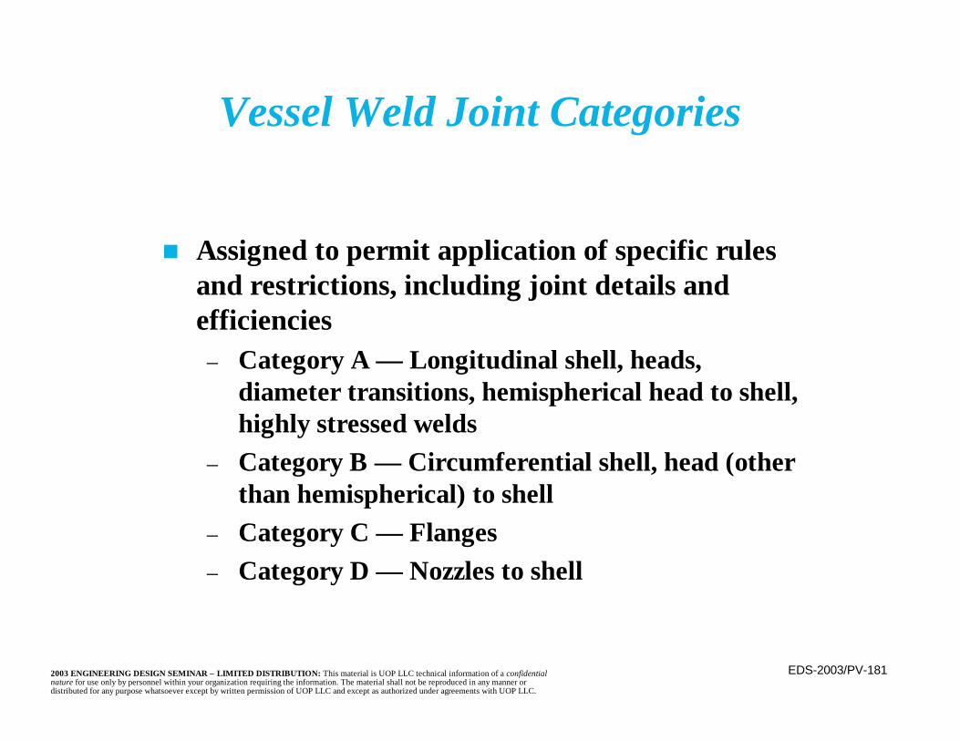
EDS-2003/PV-1812003 ENGINEERING DESIGN SEMINAR – LIMITED DISTRIBUTION: This material is UOP LLC technical information of a confidentialnature for use only by personnel within your organization requiring the information. The material shall not be reproduced in any manner ordistributed for any purpose whatsoever except by written permission of UOP LLC and except as authorized under agreements with UOP LLC.
Vessel Weld Joint Categories
n Assigned to permit application of specific rulesand restrictions, including joint details andefficiencies
– Category A — Longitudinal shell, heads,diameter transitions, hemispherical head to shell,highly stressed welds
– Category B — Circumferential shell, head (otherthan hemispherical) to shell
– Category C — Flanges– Category D — Nozzles to shell
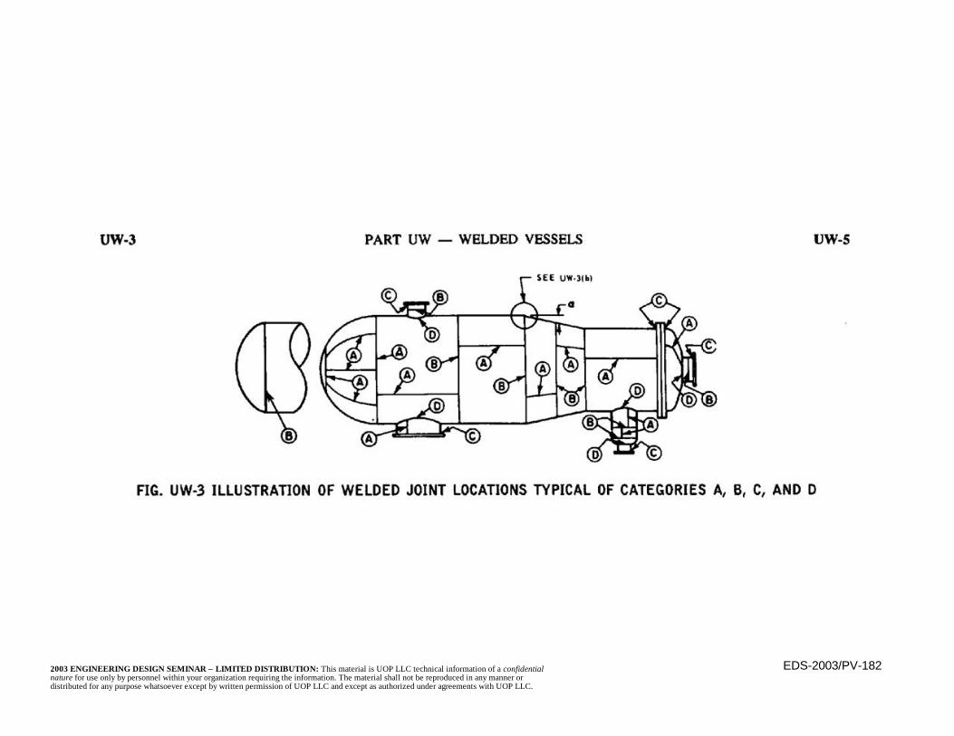
EDS-2003/PV-1822003 ENGINEERING DESIGN SEMINAR – LIMITED DISTRIBUTION: This material is UOP LLC technical information of a confidentialnature for use only by personnel within your organization requiring the information. The material shall not be reproduced in any manner ordistributed for any purpose whatsoever except by written permission of UOP LLC and except as authorized under agreements with UOP LLC.
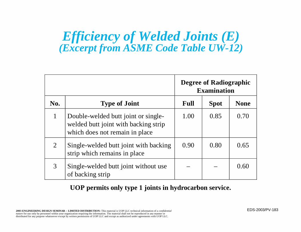
EDS-2003/PV-1832003 ENGINEERING DESIGN SEMINAR – LIMITED DISTRIBUTION: This material is UOP LLC technical information of a confidentialnature for use only by personnel within your organization requiring the information. The material shall not be reproduced in any manner ordistributed for any purpose whatsoever except by written permission of UOP LLC and except as authorized under agreements with UOP LLC.
Efficiency of Welded Joints (E)(Excerpt from ASME Code Table UW-12)
Degree of RadiographicExamination
No. Type of Joint Full Spot None
1 Double-welded butt joint or single-welded butt joint with backing stripwhich does not remain in place
1.00 0.85 0.70
2 Single-welded butt joint with backingstrip which remains in place
0.90 0.80 0.65
3 Single-welded butt joint without useof backing strip
– – 0.60
UOP permits only type 1 joints in hydrocarbon service.
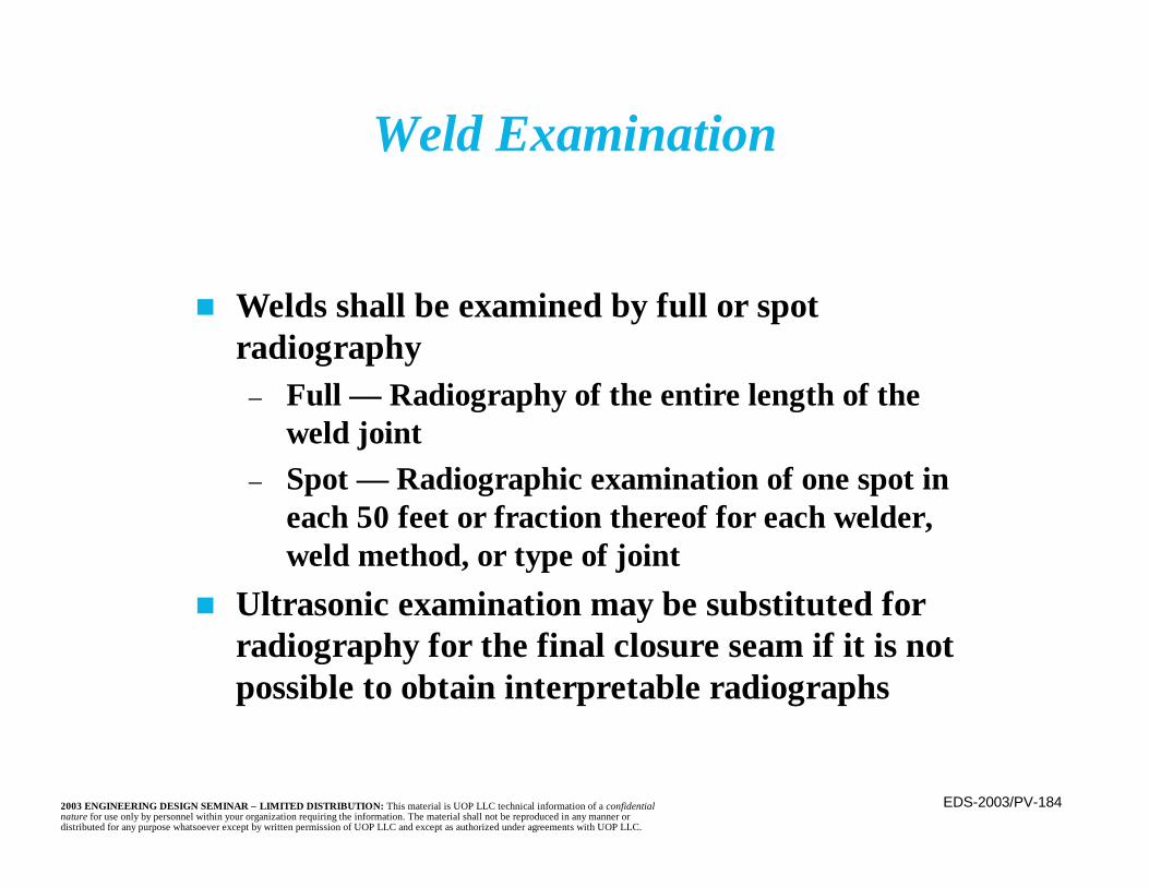
EDS-2003/PV-1842003 ENGINEERING DESIGN SEMINAR – LIMITED DISTRIBUTION: This material is UOP LLC technical information of a confidentialnature for use only by personnel within your organization requiring the information. The material shall not be reproduced in any manner ordistributed for any purpose whatsoever except by written permission of UOP LLC and except as authorized under agreements with UOP LLC.
n Welds shall be examined by full or spotradiography
– Full — Radiography of the entire length of theweld joint
– Spot — Radiographic examination of one spot ineach 50 feet or fraction thereof for each welder,weld method, or type of joint
n Ultrasonic examination may be substituted forradiography for the final closure seam if it is notpossible to obtain interpretable radiographs
Weld Examination

EDS-2003/PV-1852003 ENGINEERING DESIGN SEMINAR – LIMITED DISTRIBUTION: This material is UOP LLC technical information of a confidentialnature for use only by personnel within your organization requiring the information. The material shall not be reproduced in any manner ordistributed for any purpose whatsoever except by written permission of UOP LLC and except as authorized under agreements with UOP LLC.
n Division 1– The lower of the following at temperature:
• 2/3 yield• 1/3.5 ultimate tensile• 2/3 average rupture stress in 100,000 hours• 80% minimum stress to rupture in 100,000 hours• Average stress for creep of 1% in 100,000 hours
Section VIII, Allowable Stress Basis
EDS-2003/PV-1862003 ENGINEERING DESIGN SEMINAR – LIMITED DISTRIBUTION: This material is UOP LLC technical information of a confidentialnature for use only by personnel within your organization requiring the information. The material shall not be reproduced in any manner ordistributed for any purpose whatsoever except by written permission of UOP LLC and except as authorized under agreements with UOP LLC.
Section VIII, Allowable Stress Basis(continued)
n Division 1 (continued)– Note: For many steels, yield and tensile
strengths may first increase, then decrease astemperatures rise above ambient
• Ambient allowable is used until a lowerone is required (usually at 650°F)
– In combination with wind or earthquakeloads, allowable stress may be increased to 1.2times the values listed in the code
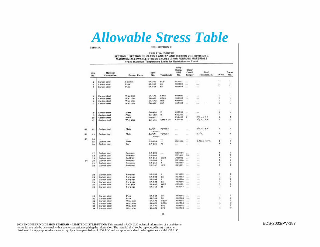
EDS-2003/PV-1872003 ENGINEERING DESIGN SEMINAR – LIMITED DISTRIBUTION: This material is UOP LLC technical information of a confidentialnature for use only by personnel within your organization requiring the information. The material shall not be reproduced in any manner ordistributed for any purpose whatsoever except by written permission of UOP LLC and except as authorized under agreements with UOP LLC.
Allowable Stress Table
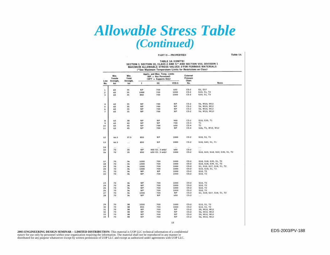
EDS-2003/PV-1882003 ENGINEERING DESIGN SEMINAR – LIMITED DISTRIBUTION: This material is UOP LLC technical information of a confidentialnature for use only by personnel within your organization requiring the information. The material shall not be reproduced in any manner ordistributed for any purpose whatsoever except by written permission of UOP LLC and except as authorized under agreements with UOP LLC.
Allowable Stress Table(Continued)

EDS-2003/PV-1892003 ENGINEERING DESIGN SEMINAR – LIMITED DISTRIBUTION: This material is UOP LLC technical information of a confidentialnature for use only by personnel within your organization requiring the information. The material shall not be reproduced in any manner ordistributed for any purpose whatsoever except by written permission of UOP LLC and except as authorized under agreements with UOP LLC.
Allowable Stress Table(Continued)
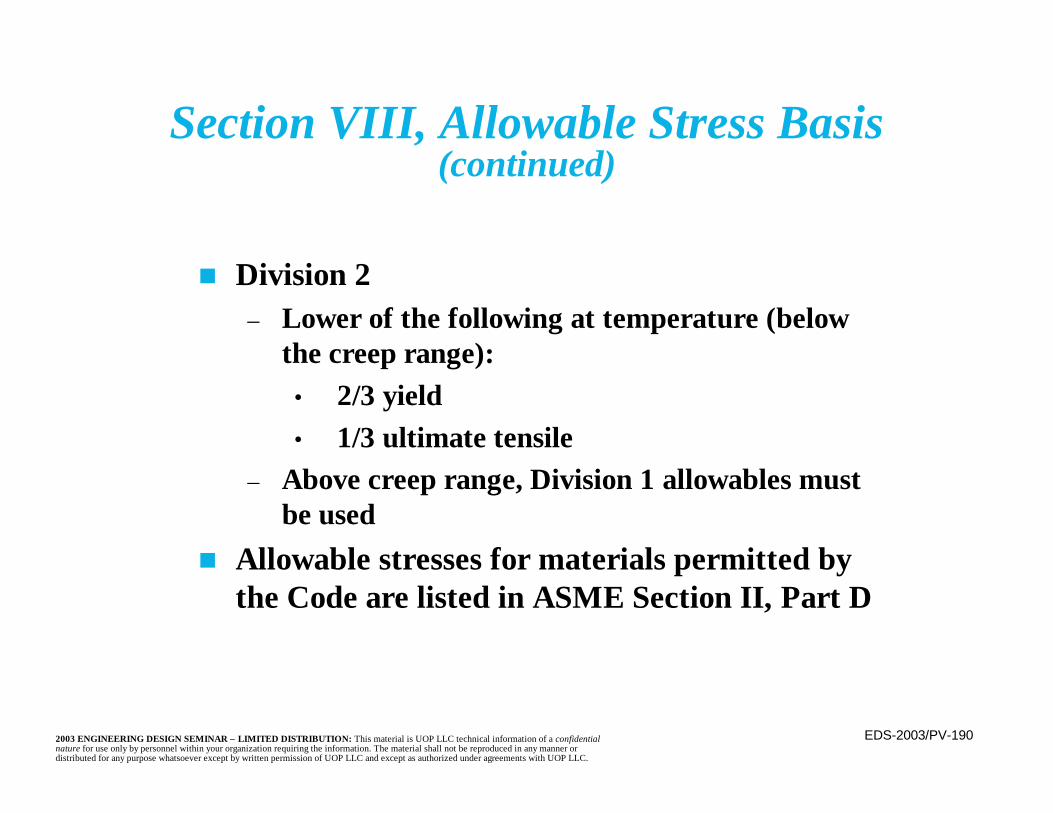
EDS-2003/PV-1902003 ENGINEERING DESIGN SEMINAR – LIMITED DISTRIBUTION: This material is UOP LLC technical information of a confidentialnature for use only by personnel within your organization requiring the information. The material shall not be reproduced in any manner ordistributed for any purpose whatsoever except by written permission of UOP LLC and except as authorized under agreements with UOP LLC.
n Division 2– Lower of the following at temperature (below
the creep range):• 2/3 yield• 1/3 ultimate tensile
– Above creep range, Division 1 allowables mustbe used
n Allowable stresses for materials permitted bythe Code are listed in ASME Section II, Part D
Section VIII, Allowable Stress Basis(continued)

EDS-2003/PV-1912003 ENGINEERING DESIGN SEMINAR – LIMITED DISTRIBUTION: This material is UOP LLC technical information of a confidentialnature for use only by personnel within your organization requiring the information. The material shall not be reproduced in any manner ordistributed for any purpose whatsoever except by written permission of UOP LLC and except as authorized under agreements with UOP LLC.
n Internal Pressure– Allowable stress is a function of material
properties
n External Pressure– Stability (buckling) becomes a concern– Allowable stress is a function of material and
geometrical properties
External Pressure Design
EDS-2003/PV-1922003 ENGINEERING DESIGN SEMINAR – LIMITED DISTRIBUTION: This material is UOP LLC technical information of a confidentialnature for use only by personnel within your organization requiring the information. The material shall not be reproduced in any manner ordistributed for any purpose whatsoever except by written permission of UOP LLC and except as authorized under agreements with UOP LLC.
n Vessel diameter fixed– Variables are:
• Length (between stiffeners)• Thickness
n Solutions– Increase t– Reduce length
n Length is decreased by adding stiffening ringsn Design procedure is trial-and-error
External Pressure Design(continued)

EDS-2003/PV-1932003 ENGINEERING DESIGN SEMINAR – LIMITED DISTRIBUTION: This material is UOP LLC technical information of a confidentialnature for use only by personnel within your organization requiring the information. The material shall not be reproduced in any manner ordistributed for any purpose whatsoever except by written permission of UOP LLC and except as authorized under agreements with UOP LLC.
External PressureDesign Length
PV-R01-39
h/3
h/3h/3
h/3
Do
Moment Axis of Ring
h = Depth of Head
t

EDS-2003/PV-1942003 ENGINEERING DESIGN SEMINAR – LIMITED DISTRIBUTION: This material is UOP LLC technical information of a confidentialnature for use only by personnel within your organization requiring the information. The material shall not be reproduced in any manner ordistributed for any purpose whatsoever except by written permission of UOP LLC and except as authorized under agreements with UOP LLC.
n Step 1– Assume a thickness t and determine the length
between stiffeners, L– Calculate L/DO, DO/t
n Step 2– Find factor A from figure G of ASME Section
II, Part Dn Step 3
– Find B, using the proper chart for the materialfrom ASME Section II, Part D
External Pressure DesignCode Design Method
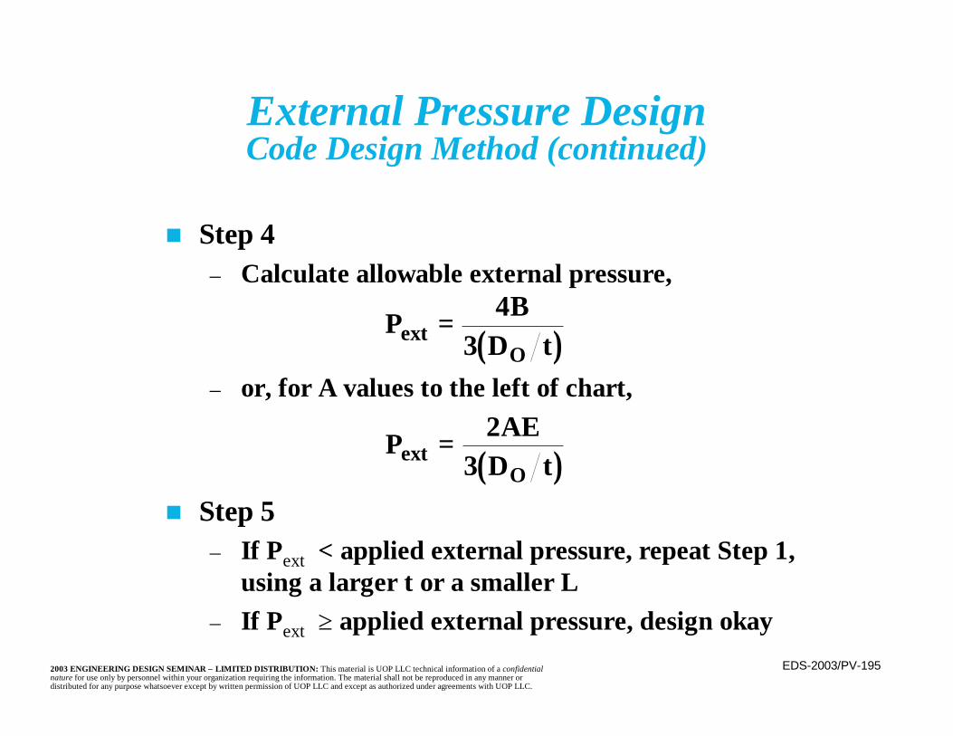
EDS-2003/PV-1952003 ENGINEERING DESIGN SEMINAR – LIMITED DISTRIBUTION: This material is UOP LLC technical information of a confidentialnature for use only by personnel within your organization requiring the information. The material shall not be reproduced in any manner ordistributed for any purpose whatsoever except by written permission of UOP LLC and except as authorized under agreements with UOP LLC.
External Pressure DesignCode Design Method (continued)
n Step 4– Calculate allowable external pressure,
– or, for A values to the left of chart,
n Step 5– If Pext < applied external pressure, repeat Step 1,
using a larger t or a smaller L– If Pext ≥ applied external pressure, design okay
( )P BD text
O= 4
3
( )P AED text
O= 2
3
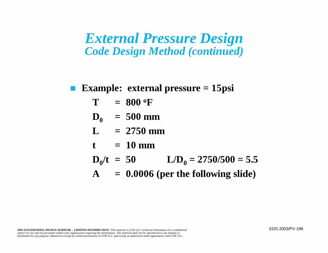
EDS-2003/PV-1962003 ENGINEERING DESIGN SEMINAR – LIMITED DISTRIBUTION: This material is UOP LLC technical information of a confidentialnature for use only by personnel within your organization requiring the information. The material shall not be reproduced in any manner ordistributed for any purpose whatsoever except by written permission of UOP LLC and except as authorized under agreements with UOP LLC.
External Pressure DesignCode Design Method (continued)
n Example: external pressure = 15psiT = 800 oFD0 = 500 mmL = 2750 mmt = 10 mmD0/t = 50 L/D0 = 2750/500 = 5.5A = 0.0006 (per the following slide)
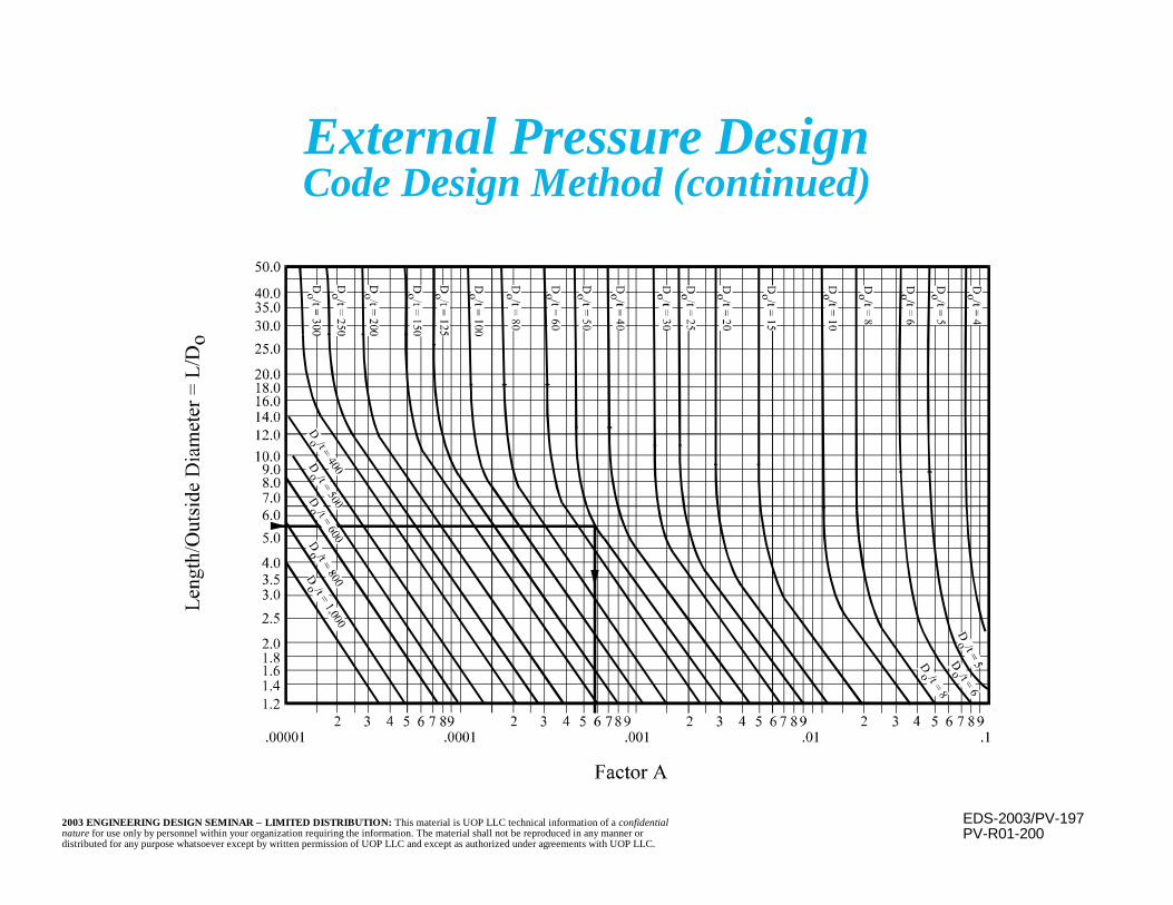
EDS-2003/PV-1972003 ENGINEERING DESIGN SEMINAR – LIMITED DISTRIBUTION: This material is UOP LLC technical information of a confidentialnature for use only by personnel within your organization requiring the information. The material shall not be reproduced in any manner ordistributed for any purpose whatsoever except by written permission of UOP LLC and except as authorized under agreements with UOP LLC.
External Pressure DesignCode Design Method (continued)
PV-R01-200
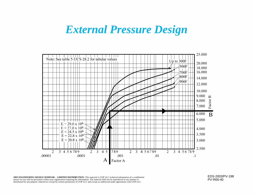
EDS-2003/PV-1982003 ENGINEERING DESIGN SEMINAR – LIMITED DISTRIBUTION: This material is UOP LLC technical information of a confidentialnature for use only by personnel within your organization requiring the information. The material shall not be reproduced in any manner ordistributed for any purpose whatsoever except by written permission of UOP LLC and except as authorized under agreements with UOP LLC.
External Pressure Design
PV-R00-40
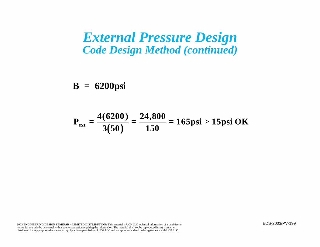
EDS-2003/PV-1992003 ENGINEERING DESIGN SEMINAR – LIMITED DISTRIBUTION: This material is UOP LLC technical information of a confidentialnature for use only by personnel within your organization requiring the information. The material shall not be reproduced in any manner ordistributed for any purpose whatsoever except by written permission of UOP LLC and except as authorized under agreements with UOP LLC.
External Pressure DesignCode Design Method (continued)
B = 6200psi
( )P 4 62003 50
24 800150
165psi 15psi OKext = = = >( ) ,
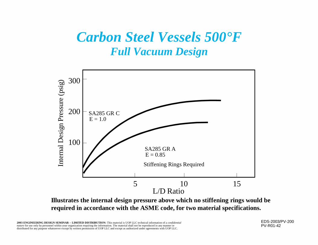
EDS-2003/PV-2002003 ENGINEERING DESIGN SEMINAR – LIMITED DISTRIBUTION: This material is UOP LLC technical information of a confidentialnature for use only by personnel within your organization requiring the information. The material shall not be reproduced in any manner ordistributed for any purpose whatsoever except by written permission of UOP LLC and except as authorized under agreements with UOP LLC.
PV-R01-42
Illustrates the internal design pressure above which no stiffening rings would berequired in accordance with the ASME code, for two material specifications.
Carbon Steel Vessels 500°FFull Vacuum Design
5L/D Ratio
300
200
100
10 15
SA285 GR CE = 1.0
Stiffening Rings Required
SA285 GR AE = 0.85
Inte
rnal
Des
ign
Pres
sure
(psi
g)

EDS-2003/PV-2012003 ENGINEERING DESIGN SEMINAR – LIMITED DISTRIBUTION: This material is UOP LLC technical information of a confidentialnature for use only by personnel within your organization requiring the information. The material shall not be reproduced in any manner ordistributed for any purpose whatsoever except by written permission of UOP LLC and except as authorized under agreements with UOP LLC.
n Maximum permitted axial compressive stress isthe lower of the following:
– Allowable tensile stress– Stress determined as follows:
• Determine (outside radius/minimum requiredthickness)(Ro/t)
• Determine A=0.125/(Ro/t)• Enter the appropriate external pressure chart
and read “B,” the allowable compressive stress• Compare the allowable stress to the applied stress• If allowable stress is less than applied stress,
increase t and repeat above steps
Axial Compression

EDS-2003/PV-2022003 ENGINEERING DESIGN SEMINAR – LIMITED DISTRIBUTION: This material is UOP LLC technical information of a confidentialnature for use only by personnel within your organization requiring the information. The material shall not be reproduced in any manner ordistributed for any purpose whatsoever except by written permission of UOP LLC and except as authorized under agreements with UOP LLC.
n Nozzle opening reduces the shell strength
n Replace cross-sectional area of metalremoved
n Available reinforcement includes excess shelland nozzle thickness
n Limits of effective reinforcement defined bythe code
Nozzle Reinforcement

EDS-2003/PV-2032003 ENGINEERING DESIGN SEMINAR – LIMITED DISTRIBUTION: This material is UOP LLC technical information of a confidentialnature for use only by personnel within your organization requiring the information. The material shall not be reproduced in any manner ordistributed for any purpose whatsoever except by written permission of UOP LLC and except as authorized under agreements with UOP LLC.
Nozzle Reinforcement(continued)
n Factor “F” used for integrally reinforcednozzles since longitudinal stress is equal tohalf of the hoop stress
n Add additional reinforcement, if required
n Additional reinforcement may be provided bysurface pads, insert plates, thickened full orpartial shell courses, or thickened nozzlenecks (integrally reinforced)
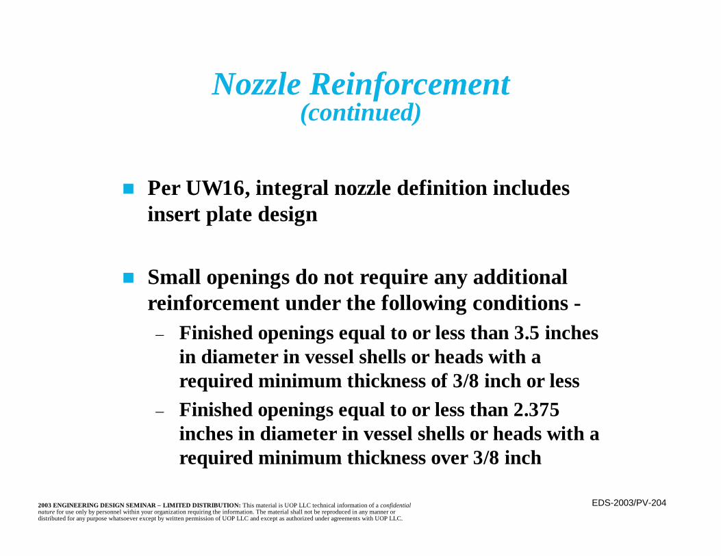
EDS-2003/PV-2042003 ENGINEERING DESIGN SEMINAR – LIMITED DISTRIBUTION: This material is UOP LLC technical information of a confidentialnature for use only by personnel within your organization requiring the information. The material shall not be reproduced in any manner ordistributed for any purpose whatsoever except by written permission of UOP LLC and except as authorized under agreements with UOP LLC.
Nozzle Reinforcement(continued)
n Per UW16, integral nozzle definition includesinsert plate design
n Small openings do not require any additionalreinforcement under the following conditions -
– Finished openings equal to or less than 3.5 inchesin diameter in vessel shells or heads with arequired minimum thickness of 3/8 inch or less
– Finished openings equal to or less than 2.375inches in diameter in vessel shells or heads with arequired minimum thickness over 3/8 inch
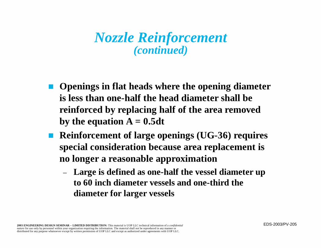
EDS-2003/PV-2052003 ENGINEERING DESIGN SEMINAR – LIMITED DISTRIBUTION: This material is UOP LLC technical information of a confidentialnature for use only by personnel within your organization requiring the information. The material shall not be reproduced in any manner ordistributed for any purpose whatsoever except by written permission of UOP LLC and except as authorized under agreements with UOP LLC.
Nozzle Reinforcement(continued)
n Openings in flat heads where the opening diameteris less than one-half the head diameter shall bereinforced by replacing half of the area removedby the equation A = 0.5dt
n Reinforcement of large openings (UG-36) requiresspecial consideration because area replacement isno longer a reasonable approximation
– Large is defined as one-half the vessel diameter upto 60 inch diameter vessels and one-third thediameter for larger vessels

EDS-2003/PV-2062003 ENGINEERING DESIGN SEMINAR – LIMITED DISTRIBUTION: This material is UOP LLC technical information of a confidentialnature for use only by personnel within your organization requiring the information. The material shall not be reproduced in any manner ordistributed for any purpose whatsoever except by written permission of UOP LLC and except as authorized under agreements with UOP LLC.
Nozzle Reinforcement
CL
αA
A
PV-R00-32

EDS-2003/PV-2072003 ENGINEERING DESIGN SEMINAR – LIMITED DISTRIBUTION: This material is UOP LLC technical information of a confidentialnature for use only by personnel within your organization requiring the information. The material shall not be reproduced in any manner ordistributed for any purpose whatsoever except by written permission of UOP LLC and except as authorized under agreements with UOP LLC.
Section A-A
PV-R00-33
Vent hole

EDS-2003/PV-2082003 ENGINEERING DESIGN SEMINAR – LIMITED DISTRIBUTION: This material is UOP LLC technical information of a confidentialnature for use only by personnel within your organization requiring the information. The material shall not be reproduced in any manner ordistributed for any purpose whatsoever except by written permission of UOP LLC and except as authorized under agreements with UOP LLC.
Nomenclature and Formulasfor Reinforced Openings
PV-R01-35
rn
2.5t or 2.5tn + teUse Smaller Value
2.5t or 2.5tn UseSmaller Value
t c
h
tn
trn
tr
d
te
d or Rn + tn + tuse larger value
d or Rn + tn + t
Reinforcement zone
Dp
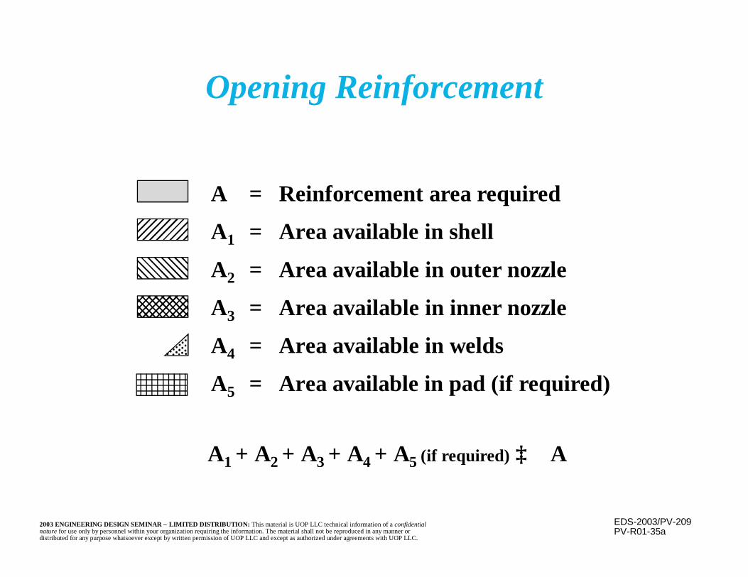
EDS-2003/PV-2092003 ENGINEERING DESIGN SEMINAR – LIMITED DISTRIBUTION: This material is UOP LLC technical information of a confidentialnature for use only by personnel within your organization requiring the information. The material shall not be reproduced in any manner ordistributed for any purpose whatsoever except by written permission of UOP LLC and except as authorized under agreements with UOP LLC.
A = Reinforcement area required
A1 = Area available in shell
A2 = Area available in outer nozzle
A3 = Area available in inner nozzle
A4 = Area available in welds
A5 = Area available in pad (if required)
PV-R01-35a
A1 + A2 + A3 + A4 + A5 (if required) ≥ A
Opening Reinforcement
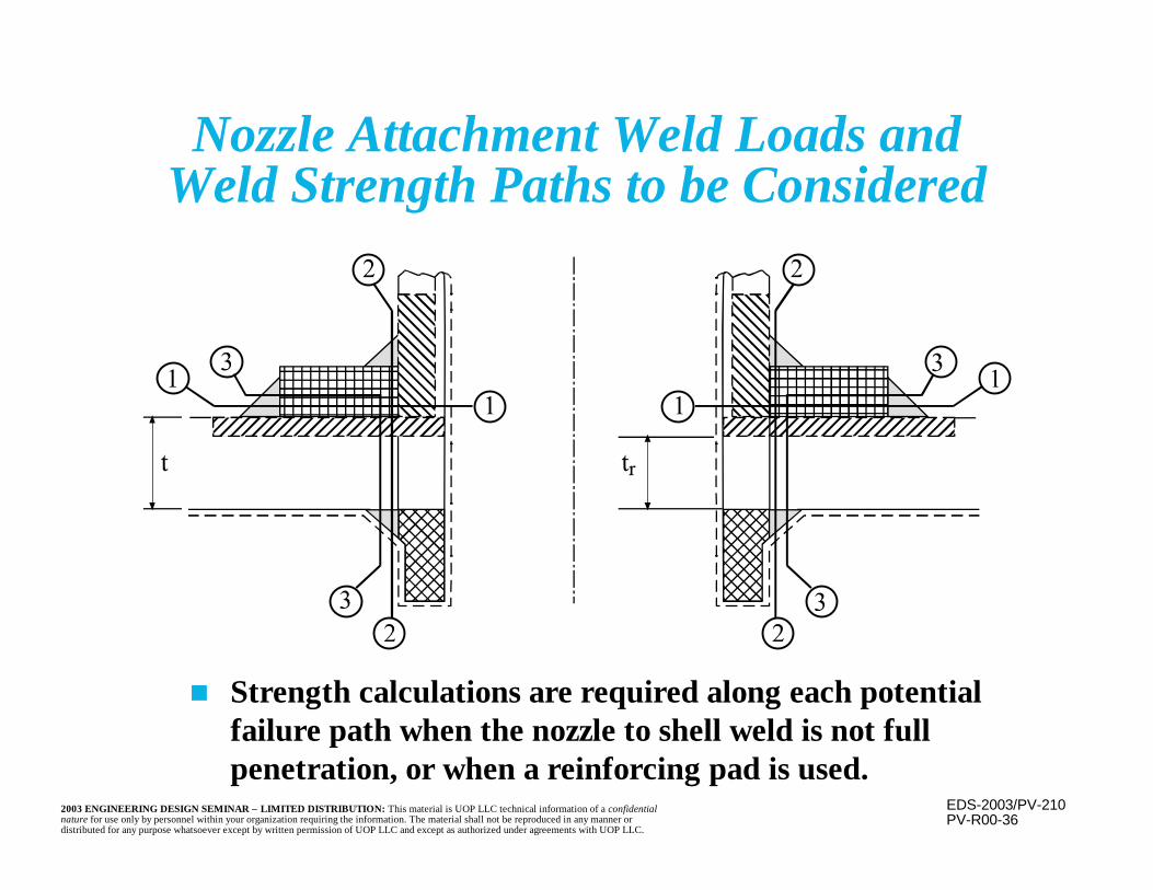
EDS-2003/PV-2102003 ENGINEERING DESIGN SEMINAR – LIMITED DISTRIBUTION: This material is UOP LLC technical information of a confidentialnature for use only by personnel within your organization requiring the information. The material shall not be reproduced in any manner ordistributed for any purpose whatsoever except by written permission of UOP LLC and except as authorized under agreements with UOP LLC.
PV-R00-36
n Strength calculations are required along each potentialfailure path when the nozzle to shell weld is not fullpenetration, or when a reinforcing pad is used.
Nozzle Attachment Weld Loads andWeld Strength Paths to be Considered
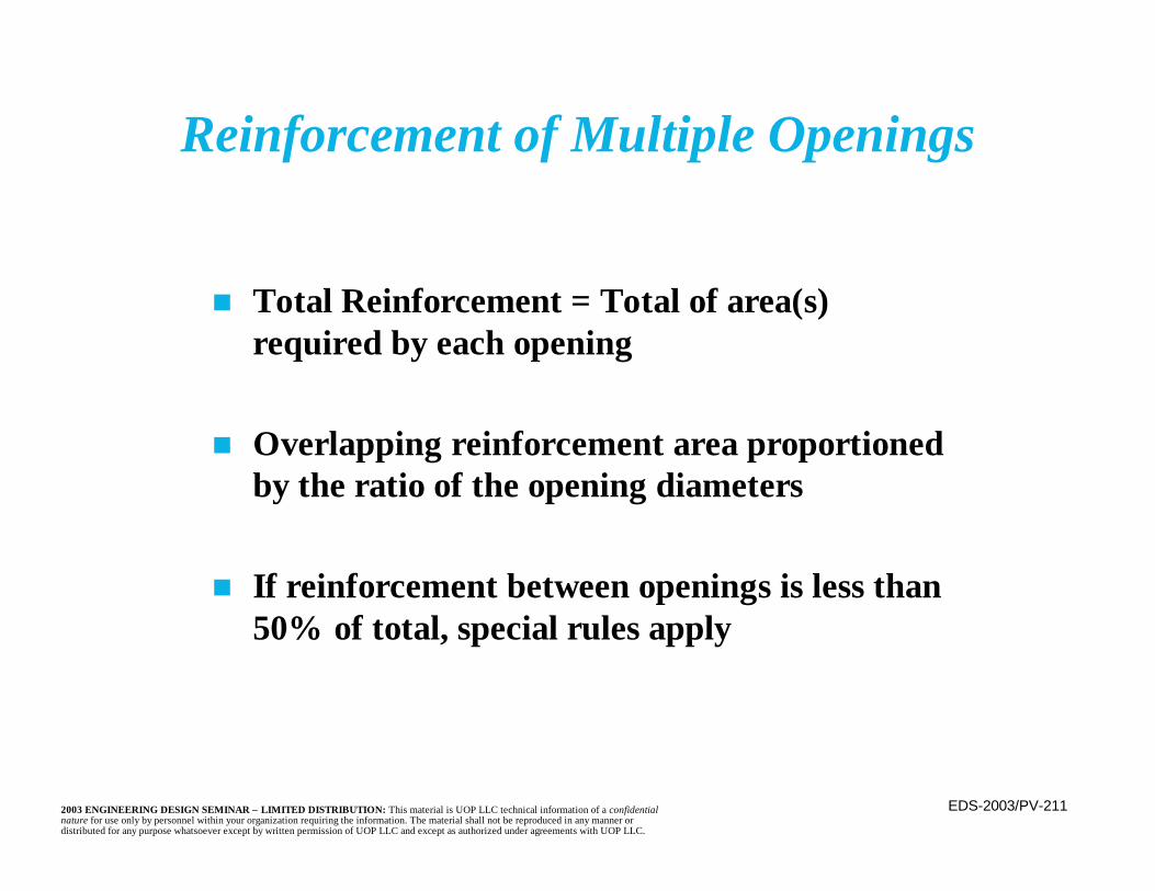
EDS-2003/PV-2112003 ENGINEERING DESIGN SEMINAR – LIMITED DISTRIBUTION: This material is UOP LLC technical information of a confidentialnature for use only by personnel within your organization requiring the information. The material shall not be reproduced in any manner ordistributed for any purpose whatsoever except by written permission of UOP LLC and except as authorized under agreements with UOP LLC.
n Total Reinforcement = Total of area(s)required by each opening
n Overlapping reinforcement area proportionedby the ratio of the opening diameters
n If reinforcement between openings is less than50% of total, special rules apply
Reinforcement of Multiple Openings

EDS-2003/PV-2122003 ENGINEERING DESIGN SEMINAR – LIMITED DISTRIBUTION: This material is UOP LLC technical information of a confidentialnature for use only by personnel within your organization requiring the information. The material shall not be reproduced in any manner ordistributed for any purpose whatsoever except by written permission of UOP LLC and except as authorized under agreements with UOP LLC.
Reinforcement of Multiple Openings(continued)
n Each pair of three or more openings must beat least 11/3 times the average diameter apart
– If not, then there is no credit for area betweenthe openings
n In all cases, an opening that encompasses allof the actual openings may be assumed andreinforced
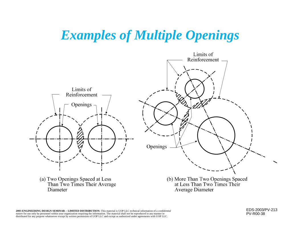
EDS-2003/PV-2132003 ENGINEERING DESIGN SEMINAR – LIMITED DISTRIBUTION: This material is UOP LLC technical information of a confidentialnature for use only by personnel within your organization requiring the information. The material shall not be reproduced in any manner ordistributed for any purpose whatsoever except by written permission of UOP LLC and except as authorized under agreements with UOP LLC.
Examples of Multiple Openings
PV-R00-38

EDS-2003/PV-2142003 ENGINEERING DESIGN SEMINAR – LIMITED DISTRIBUTION: This material is UOP LLC technical information of a confidentialnature for use only by personnel within your organization requiring the information. The material shall not be reproduced in any manner ordistributed for any purpose whatsoever except by written permission of UOP LLC and except as authorized under agreements with UOP LLC.
External Loads on Nozzles
n Imposed loads on nozzles are generally not aproblem for the vessel shell
– Maintaining a flange seal usually governsn Several analytical methods exist to evaluate
local shell stresses from imposed loads– Welding Research Council Bulletin 107– Welding Research Council Bulletin 297
n WRC 297 is somewhat more accurate, but islimited to cylindrical shells
EDS-2003/PV-2152003 ENGINEERING DESIGN SEMINAR – LIMITED DISTRIBUTION: This material is UOP LLC technical information of a confidentialnature for use only by personnel within your organization requiring the information. The material shall not be reproduced in any manner ordistributed for any purpose whatsoever except by written permission of UOP LLC and except as authorized under agreements with UOP LLC.
Design of Tall Vertical Vessels
n In addition to hoop (circumferential) stresses,tall vessels must consider longitudinal stress,which may govern the wall thickness
n Weight– Weight of the vessel will impose compressive
stresses in the shell (tensile stresses when theshell is below the supports— i.e., it’s hanging)
– Weight of internals and contents supported bythe shell above the point being considered alsocontribute to shell loadings
EDS-2003/PV-2162003 ENGINEERING DESIGN SEMINAR – LIMITED DISTRIBUTION: This material is UOP LLC technical information of a confidentialnature for use only by personnel within your organization requiring the information. The material shall not be reproduced in any manner ordistributed for any purpose whatsoever except by written permission of UOP LLC and except as authorized under agreements with UOP LLC.
Design of Tall Vertical Vessels(continued)
n Pressure– Internal pressure imposes tensile stresses on
the shell– External pressure imposes compressive
stresses on the shell
EDS-2003/PV-2172003 ENGINEERING DESIGN SEMINAR – LIMITED DISTRIBUTION: This material is UOP LLC technical information of a confidentialnature for use only by personnel within your organization requiring the information. The material shall not be reproduced in any manner ordistributed for any purpose whatsoever except by written permission of UOP LLC and except as authorized under agreements with UOP LLC.
Design of Tall Vertical Vessels(continued)
n Moment Loadings– External loadings produce an overturning moment
and resulting tensile and compressive longitudinalstresses at the bottom of tall vertical vessels.
– Common sources of large external moments are:• Wind• Earthquake• Eccentricity• Forces from piping weight, thermal expansion,
and expansion joints– Wind and earthquake are short term loadings;
others are long term sustained loads.

EDS-2003/PV-2182003 ENGINEERING DESIGN SEMINAR – LIMITED DISTRIBUTION: This material is UOP LLC technical information of a confidentialnature for use only by personnel within your organization requiring the information. The material shall not be reproduced in any manner ordistributed for any purpose whatsoever except by written permission of UOP LLC and except as authorized under agreements with UOP LLC.
Design Cases
n Erection – Greatest tensile uplift on the skirtand anchor bolts due to the least weight andthe full moment
n Design – Greatest longitudinal tensile shellstress due to high internal pressure coupledwith full moment
n Operatingn Shutdown – Greatest compressive loadings due
to lack of internal pressure but full weight andmoment
EDS-2003/PV-2192003 ENGINEERING DESIGN SEMINAR – LIMITED DISTRIBUTION: This material is UOP LLC technical information of a confidentialnature for use only by personnel within your organization requiring the information. The material shall not be reproduced in any manner ordistributed for any purpose whatsoever except by written permission of UOP LLC and except as authorized under agreements with UOP LLC.
Design Cases(continued)
n Long-Term Operation – Evaluating sustainedloads (e.g., expansion joint operating forces)
n Short Term – Evaluated short term loads, e.g.,expansion joint blow out forces
n Hydrotest – use reduced magnitudes of wind load
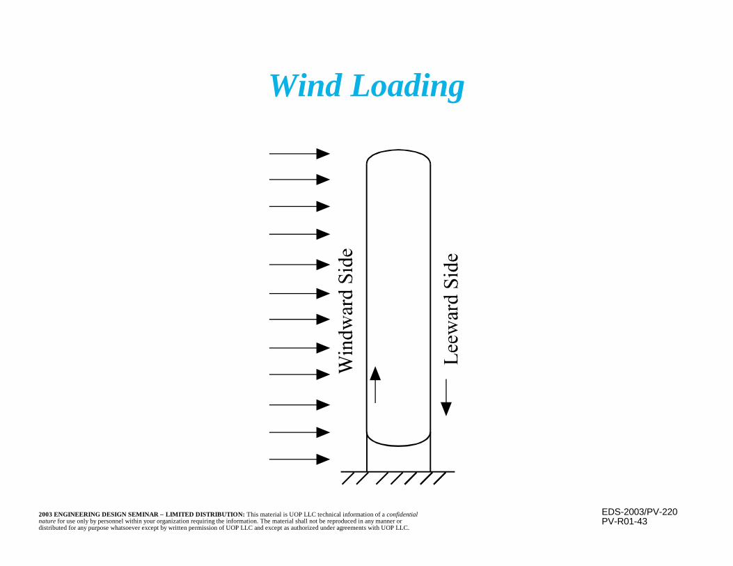
EDS-2003/PV-2202003 ENGINEERING DESIGN SEMINAR – LIMITED DISTRIBUTION: This material is UOP LLC technical information of a confidentialnature for use only by personnel within your organization requiring the information. The material shall not be reproduced in any manner ordistributed for any purpose whatsoever except by written permission of UOP LLC and except as authorized under agreements with UOP LLC.
PV-R01-43
Wind Loading
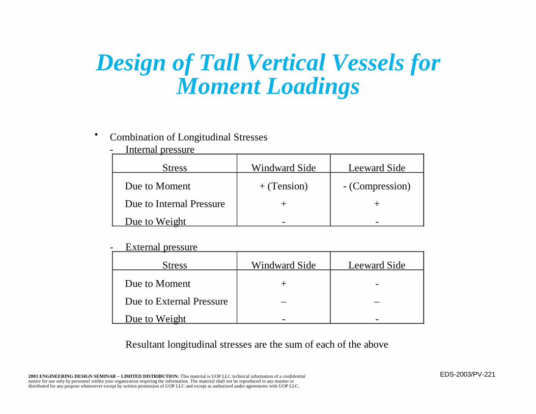
EDS-2003/PV-2212003 ENGINEERING DESIGN SEMINAR – LIMITED DISTRIBUTION: This material is UOP LLC technical information of a confidentialnature for use only by personnel within your organization requiring the information. The material shall not be reproduced in any manner ordistributed for any purpose whatsoever except by written permission of UOP LLC and except as authorized under agreements with UOP LLC.
Design of Tall Vertical Vessels forMoment Loadings
• Combination of Longitudinal Stresses- Internal pressure
Stress Windward Side Leeward Side
Due to Moment
Due to Internal Pressure
Due to Weight
+ (Tension)
+
-
- (Compression)
+
-
- External pressure
Stress Windward Side Leeward Side
Due to Moment
Due to External Pressure
Due to Weight
+
–
-
-
–
-
Resultant longitudinal stresses are the sum of each of the above
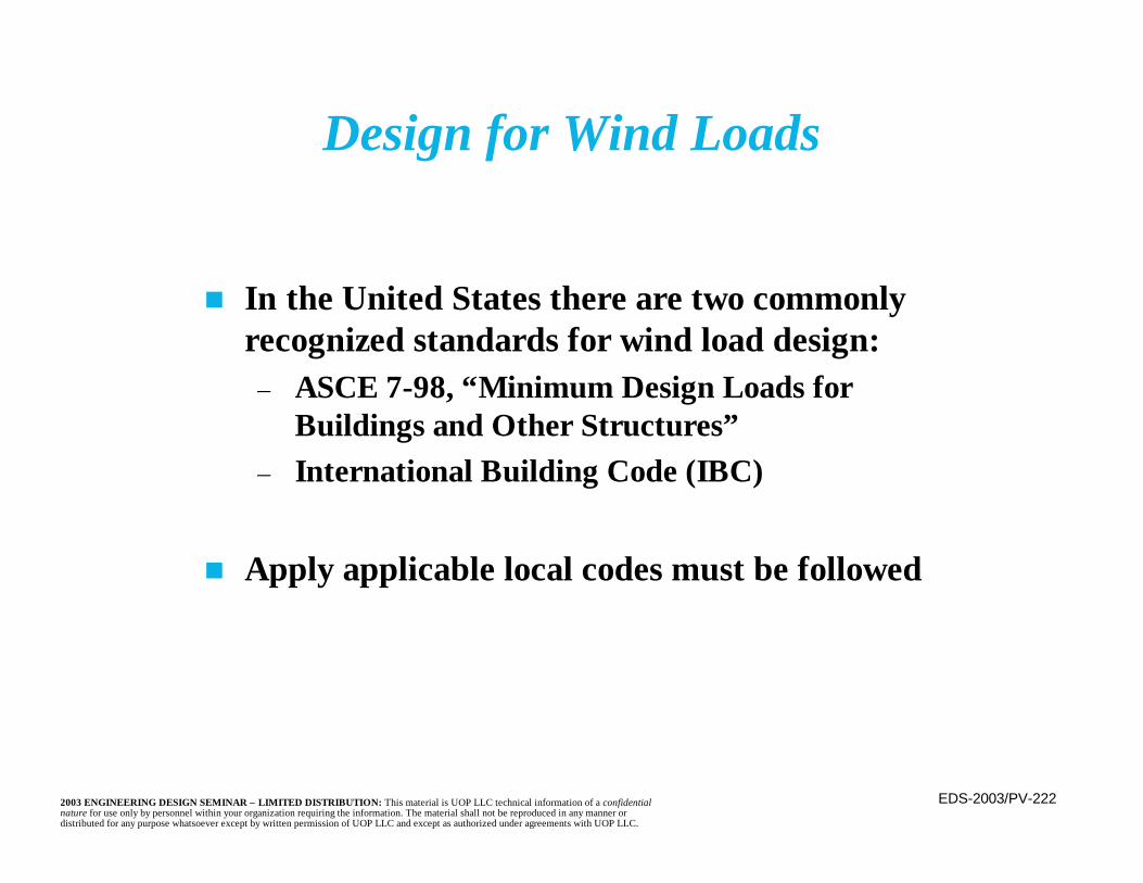
EDS-2003/PV-2222003 ENGINEERING DESIGN SEMINAR – LIMITED DISTRIBUTION: This material is UOP LLC technical information of a confidentialnature for use only by personnel within your organization requiring the information. The material shall not be reproduced in any manner ordistributed for any purpose whatsoever except by written permission of UOP LLC and except as authorized under agreements with UOP LLC.
n In the United States there are two commonlyrecognized standards for wind load design:
– ASCE 7-98, “Minimum Design Loads forBuildings and Other Structures”
– International Building Code (IBC)
n Apply applicable local codes must be followed
Design for Wind Loads
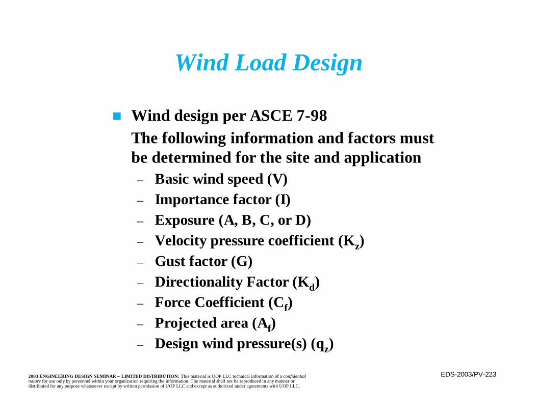
EDS-2003/PV-2232003 ENGINEERING DESIGN SEMINAR – LIMITED DISTRIBUTION: This material is UOP LLC technical information of a confidentialnature for use only by personnel within your organization requiring the information. The material shall not be reproduced in any manner ordistributed for any purpose whatsoever except by written permission of UOP LLC and except as authorized under agreements with UOP LLC.
n Wind design per ASCE 7-98The following information and factors mustbe determined for the site and application
– Basic wind speed (V)– Importance factor (I)– Exposure (A, B, C, or D)– Velocity pressure coefficient (Kz)– Gust factor (G)– Directionality Factor (Kd)– Force Coefficient (Cf)– Projected area (Af)– Design wind pressure(s) (qz)
Wind Load Design
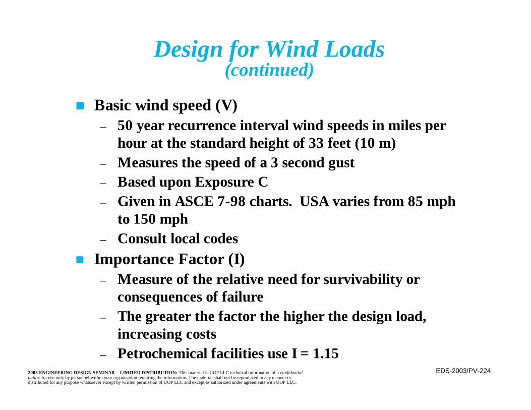
EDS-2003/PV-2242003 ENGINEERING DESIGN SEMINAR – LIMITED DISTRIBUTION: This material is UOP LLC technical information of a confidentialnature for use only by personnel within your organization requiring the information. The material shall not be reproduced in any manner ordistributed for any purpose whatsoever except by written permission of UOP LLC and except as authorized under agreements with UOP LLC.
n Basic wind speed (V)– 50 year recurrence interval wind speeds in miles per
hour at the standard height of 33 feet (10 m)– Measures the speed of a 3 second gust– Based upon Exposure C– Given in ASCE 7-98 charts. USA varies from 85 mph
to 150 mph– Consult local codes
n Importance Factor (I)– Measure of the relative need for survivability or
consequences of failure– The greater the factor the higher the design load,
increasing costs– Petrochemical facilities use I = 1.15
Design for Wind Loads(continued)

EDS-2003/PV-2252003 ENGINEERING DESIGN SEMINAR – LIMITED DISTRIBUTION: This material is UOP LLC technical information of a confidentialnature for use only by personnel within your organization requiring the information. The material shall not be reproduced in any manner ordistributed for any purpose whatsoever except by written permission of UOP LLC and except as authorized under agreements with UOP LLC.
Design for Wind Loads(continued)
n Exposure– A measure of the surrounding conditions and
wind obstructions– Range from A (center of large cities) to D
(unobstructed areas areas within 1500 feet ofopen water 1 mile or greater in width)
– The default for refinery design is Exposure C– Within each exposure, non building structures
are denoted as Case 2

EDS-2003/PV-2262003 ENGINEERING DESIGN SEMINAR – LIMITED DISTRIBUTION: This material is UOP LLC technical information of a confidentialnature for use only by personnel within your organization requiring the information. The material shall not be reproduced in any manner ordistributed for any purpose whatsoever except by written permission of UOP LLC and except as authorized under agreements with UOP LLC.
Design for Wind Loads(continued)
n Velocity Pressure Coefficient (Kz)– Accounts for the exposure and the height
above grade– Wind pressure increase with height for a
given basic wind speed– Given in tables in ASCE 7-98
n Gust Factor (G)– Accounts for the dynamic response to gusts– For most refinery equipment G = 0.85
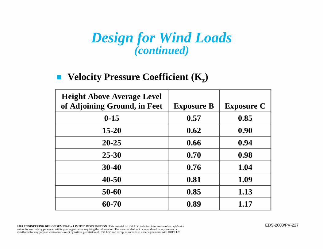
EDS-2003/PV-2272003 ENGINEERING DESIGN SEMINAR – LIMITED DISTRIBUTION: This material is UOP LLC technical information of a confidentialnature for use only by personnel within your organization requiring the information. The material shall not be reproduced in any manner ordistributed for any purpose whatsoever except by written permission of UOP LLC and except as authorized under agreements with UOP LLC.
Height Above Average Levelof Adjoining Ground, in Feet Exposure B Exposure C
0-15 0.57 0.8515-20 0.62 0.9020-25 0.66 0.9425-30 0.70 0.9830-40 0.76 1.0440-50 0.81 1.0950-60 0.85 1.1360-70 0.89 1.17
n Velocity Pressure Coefficient (Kz)
Design for Wind Loads(continued)

EDS-2003/PV-2282003 ENGINEERING DESIGN SEMINAR – LIMITED DISTRIBUTION: This material is UOP LLC technical information of a confidentialnature for use only by personnel within your organization requiring the information. The material shall not be reproduced in any manner ordistributed for any purpose whatsoever except by written permission of UOP LLC and except as authorized under agreements with UOP LLC.
Design for Wind Loads(continued)
n Directionality Factor (Kd)– Used with load combinations defined in ASCE
7-98– For round structures use Kd = 0.95– Use of Kd = 1 is only slightly conservative
n Force Coefficient (Cf)– Accounts for the streamlining effect of the shape– For round structures Cf = 0.8 in most cases
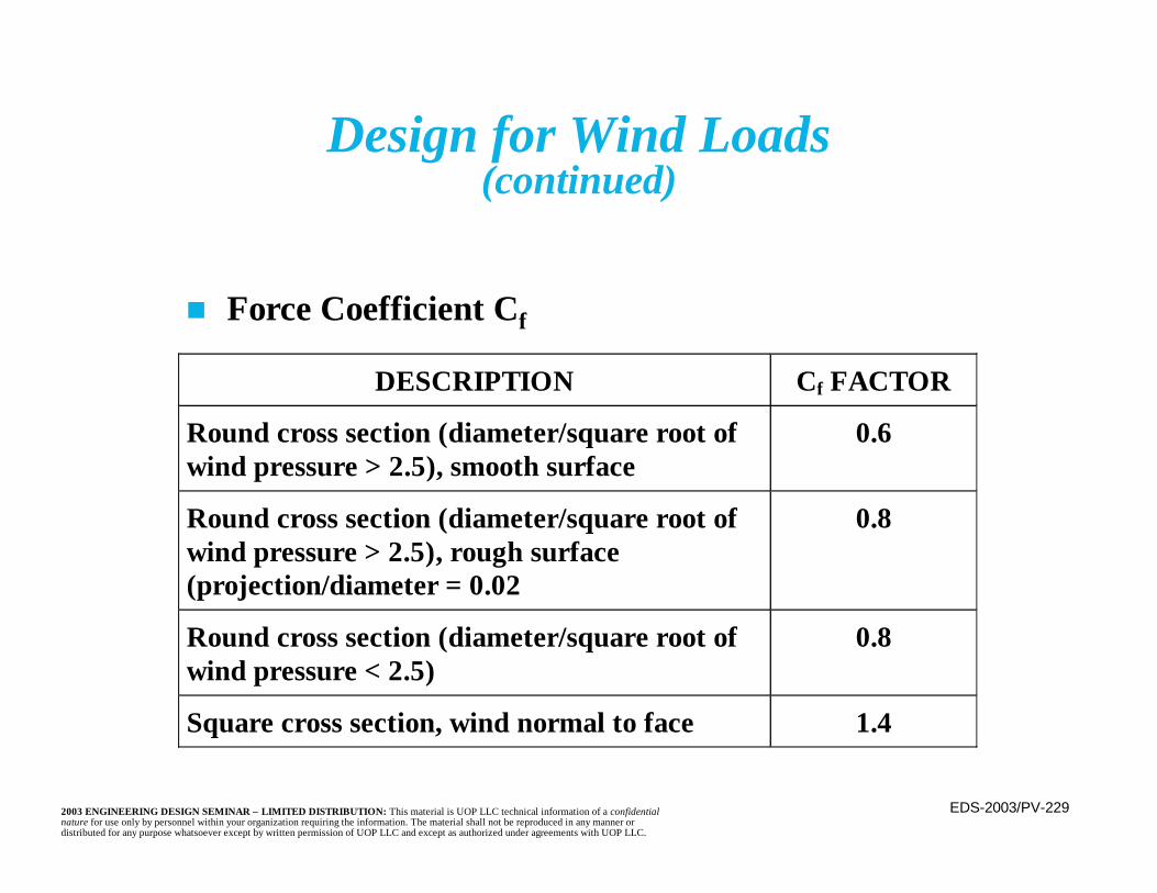
EDS-2003/PV-2292003 ENGINEERING DESIGN SEMINAR – LIMITED DISTRIBUTION: This material is UOP LLC technical information of a confidentialnature for use only by personnel within your organization requiring the information. The material shall not be reproduced in any manner ordistributed for any purpose whatsoever except by written permission of UOP LLC and except as authorized under agreements with UOP LLC.
Design for Wind Loads(continued)
DESCRIPTION Cf FACTOR
Round cross section (diameter/square root ofwind pressure > 2.5), smooth surface
0.6
Round cross section (diameter/square root ofwind pressure > 2.5), rough surface(projection/diameter = 0.02
0.8
Round cross section (diameter/square root ofwind pressure < 2.5)
0.8
Square cross section, wind normal to face 1.4
n Force Coefficient Cf
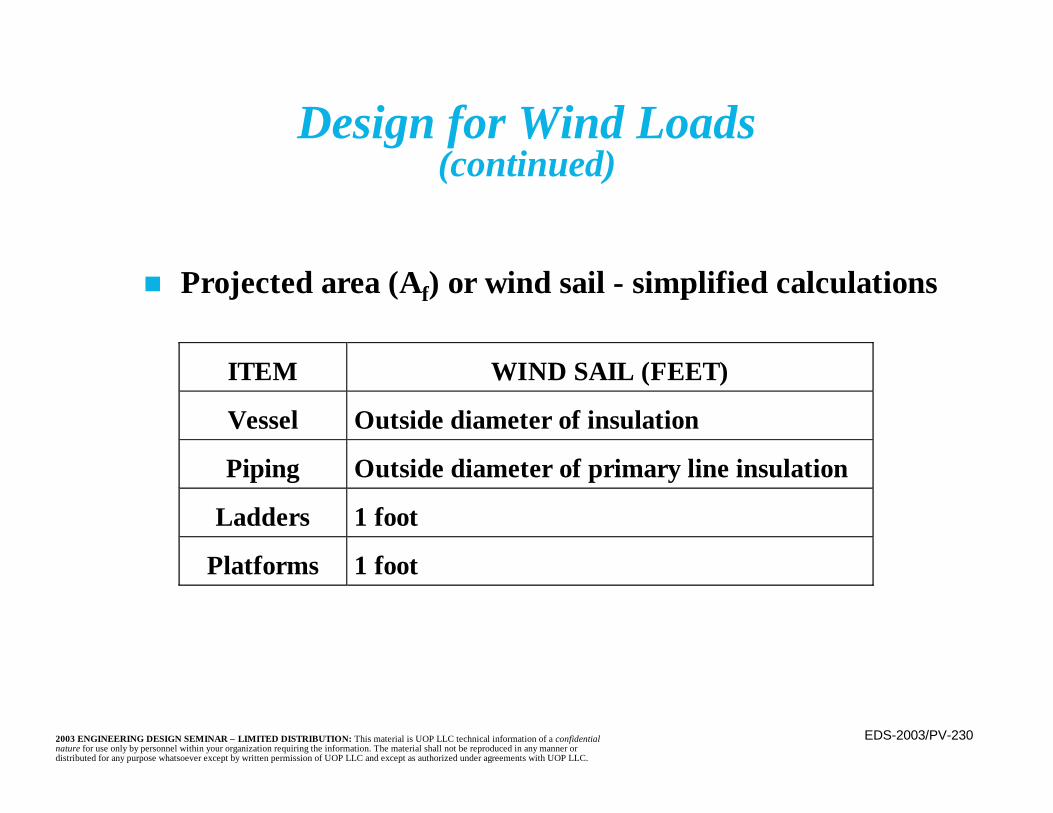
EDS-2003/PV-2302003 ENGINEERING DESIGN SEMINAR – LIMITED DISTRIBUTION: This material is UOP LLC technical information of a confidentialnature for use only by personnel within your organization requiring the information. The material shall not be reproduced in any manner ordistributed for any purpose whatsoever except by written permission of UOP LLC and except as authorized under agreements with UOP LLC.
Design for Wind Loads(continued)
ITEM WIND SAIL (FEET)
Vessel Outside diameter of insulation
Piping Outside diameter of primary line insulation
Ladders 1 foot
Platforms 1 foot
n Projected area (Af) or wind sail - simplified calculations
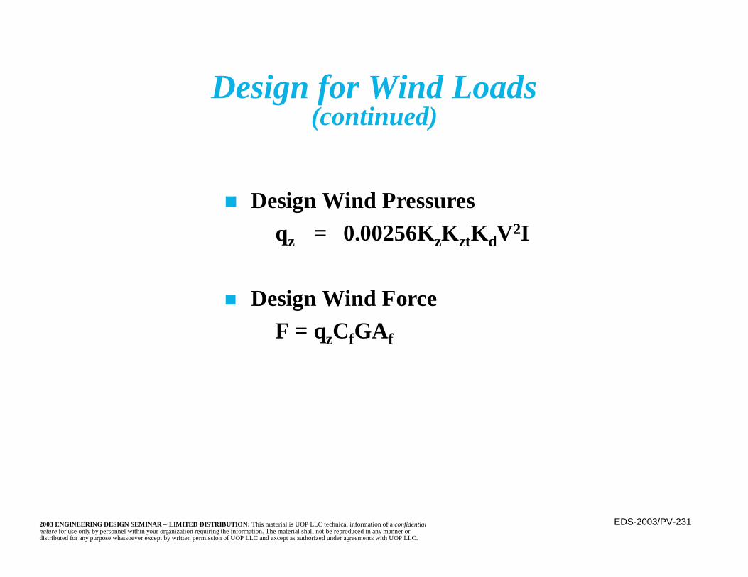
EDS-2003/PV-2312003 ENGINEERING DESIGN SEMINAR – LIMITED DISTRIBUTION: This material is UOP LLC technical information of a confidentialnature for use only by personnel within your organization requiring the information. The material shall not be reproduced in any manner ordistributed for any purpose whatsoever except by written permission of UOP LLC and except as authorized under agreements with UOP LLC.
n Design Wind Pressuresqz = 0.00256KzKztKdV2I
n Design Wind ForceF = qzCfGAf
Design for Wind Loads(continued)
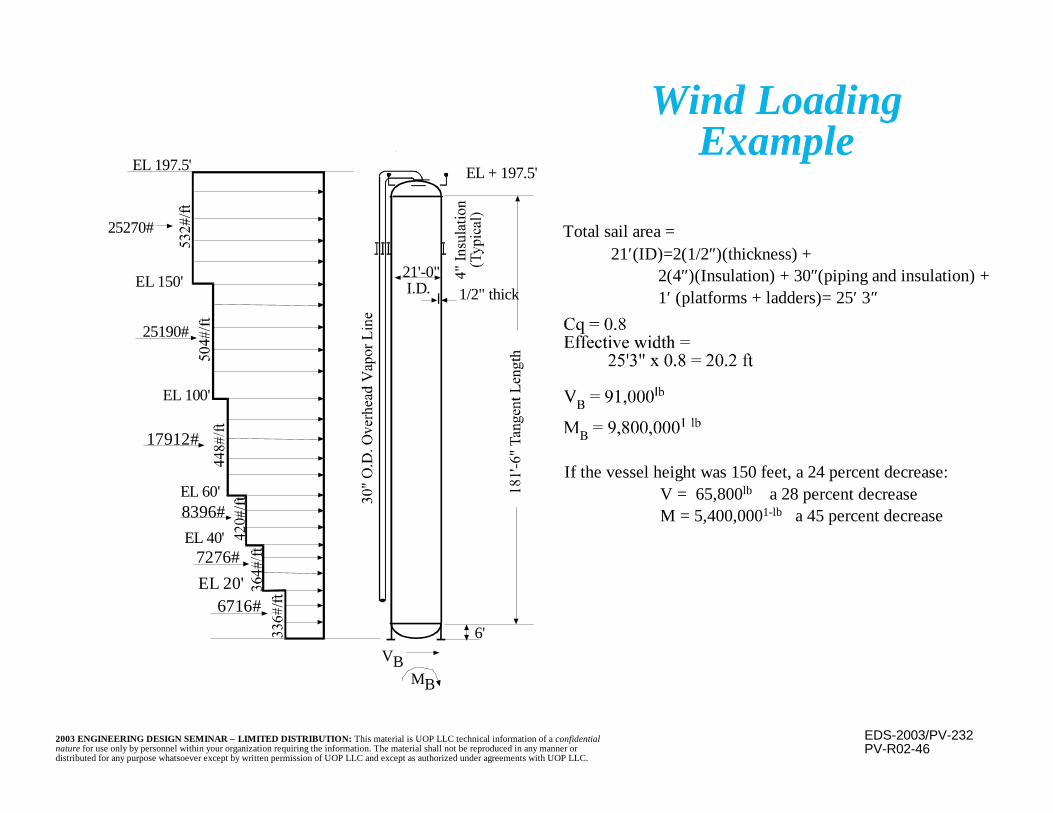
EDS-2003/PV-2322003 ENGINEERING DESIGN SEMINAR – LIMITED DISTRIBUTION: This material is UOP LLC technical information of a confidentialnature for use only by personnel within your organization requiring the information. The material shall not be reproduced in any manner ordistributed for any purpose whatsoever except by written permission of UOP LLC and except as authorized under agreements with UOP LLC.
Wind LoadingExample
PV-R02-46
If the vessel height was 150 feet, a 24 percent decrease:V = 65,800lb a 28 percent decreaseM = 5,400,0001-lb a 45 percent decrease
Total sail area =21′(ID)=2(1/2″)(thickness) +
2(4″)(Insulation) + 30″(piping and insulation) + 1′ (platforms + ladders)= 25′ 3″
6716#EL 20'
EL 197.5'
21'-0"EL 150'
EL 100'
EL 40'
8396#
7276#
EL 60'
17912#
25190#
I.D. 1/2" thick
EL + 197.5'
6'
25270#
VBMB
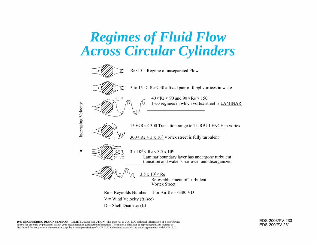
EDS-2003/PV-2332003 ENGINEERING DESIGN SEMINAR – LIMITED DISTRIBUTION: This material is UOP LLC technical information of a confidentialnature for use only by personnel within your organization requiring the information. The material shall not be reproduced in any manner ordistributed for any purpose whatsoever except by written permission of UOP LLC and except as authorized under agreements with UOP LLC.
Regimes of Fluid FlowAcross Circular Cylinders
EDS-200/PV-231
<
< < < <
< <
< <
<<
<
<
<
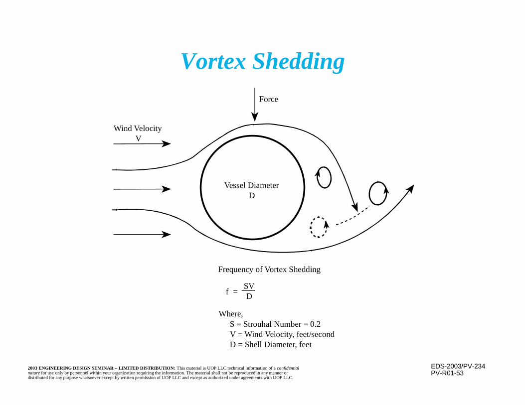
EDS-2003/PV-2342003 ENGINEERING DESIGN SEMINAR – LIMITED DISTRIBUTION: This material is UOP LLC technical information of a confidentialnature for use only by personnel within your organization requiring the information. The material shall not be reproduced in any manner ordistributed for any purpose whatsoever except by written permission of UOP LLC and except as authorized under agreements with UOP LLC.
PV-R01-53
Vortex Shedding
Wind VelocityV
Force
Frequency of Vortex Shedding
S = Strouhal Number = 0.2V = Wind Velocity, feet/secondD = Shell Diameter, feet
Where,
f =SVD
Vessel DiameterD
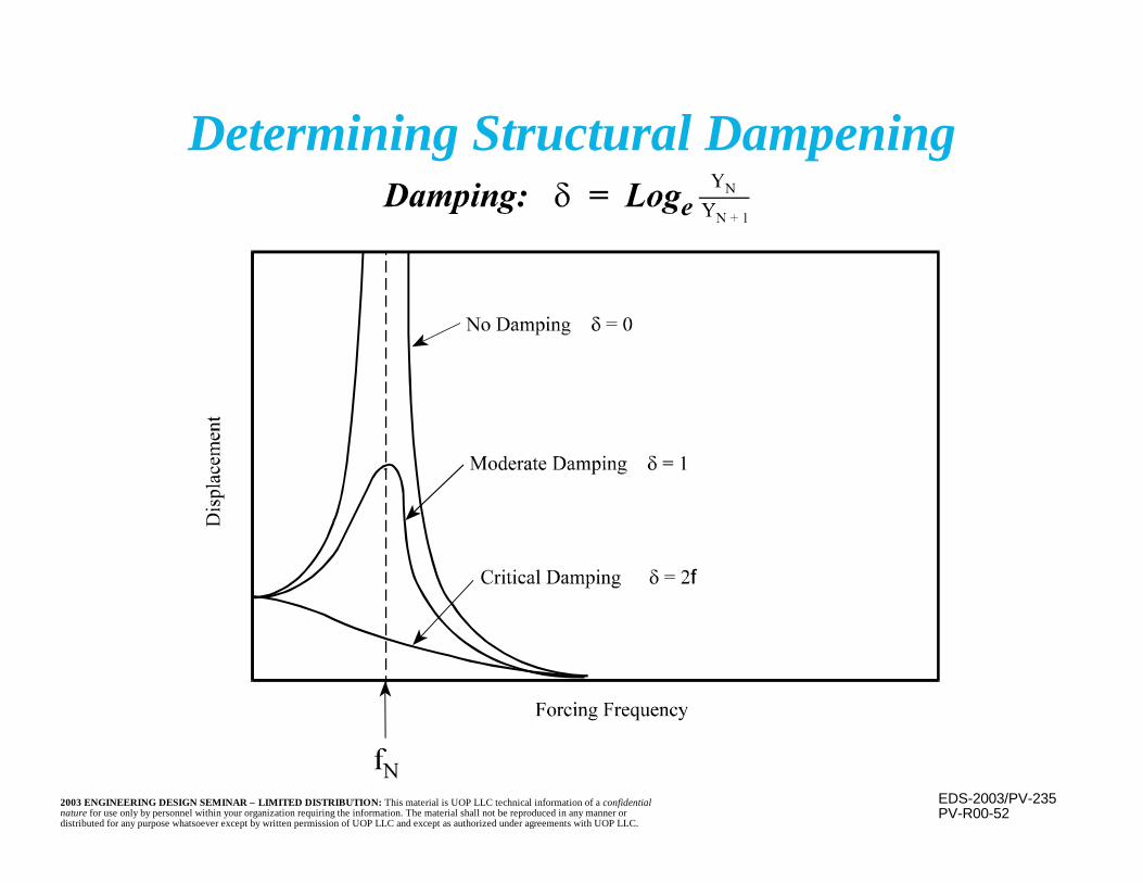
EDS-2003/PV-2352003 ENGINEERING DESIGN SEMINAR – LIMITED DISTRIBUTION: This material is UOP LLC technical information of a confidentialnature for use only by personnel within your organization requiring the information. The material shall not be reproduced in any manner ordistributed for any purpose whatsoever except by written permission of UOP LLC and except as authorized under agreements with UOP LLC.
PV-R00-52
Determining Structural Dampening

EDS-2003/PV-2362003 ENGINEERING DESIGN SEMINAR – LIMITED DISTRIBUTION: This material is UOP LLC technical information of a confidentialnature for use only by personnel within your organization requiring the information. The material shall not be reproduced in any manner ordistributed for any purpose whatsoever except by written permission of UOP LLC and except as authorized under agreements with UOP LLC.
PV-R00-56
Critical Wind Velocity
EDS-2003/PV-2372003 ENGINEERING DESIGN SEMINAR – LIMITED DISTRIBUTION: This material is UOP LLC technical information of a confidentialnature for use only by personnel within your organization requiring the information. The material shall not be reproduced in any manner ordistributed for any purpose whatsoever except by written permission of UOP LLC and except as authorized under agreements with UOP LLC.
n Historically a simplified static force procedurehas been used and is illustrated here
n The recently released International BuildingCode (IBC) requires a more detailed, dynamicanalysis in many cases
n In the static force method an “equivalent” shearforce is determined and distributed along thevessel
Seismic (Earthquake) Design

EDS-2003/PV-2382003 ENGINEERING DESIGN SEMINAR – LIMITED DISTRIBUTION: This material is UOP LLC technical information of a confidentialnature for use only by personnel within your organization requiring the information. The material shall not be reproduced in any manner ordistributed for any purpose whatsoever except by written permission of UOP LLC and except as authorized under agreements with UOP LLC.
n Static load method:Shear Force,where:V = Design lateral forceZ = Seismic zone factor (varies from 0.075 to 0.40)W = Dead load (weight)RW = Stiffness coefficient (4 for skirt supported vessels)I = Importance factor (use 1.25)C = Coefficient dependent upon soil conditions
and the vessel’s period of vibrationS = Site coefficient, generally take as 1.5T = Period for a vertical cylindrical vessel =
WRZICV
W=
8EIwL0.258
4
32TS25.1C =
Seismic Design(continued)
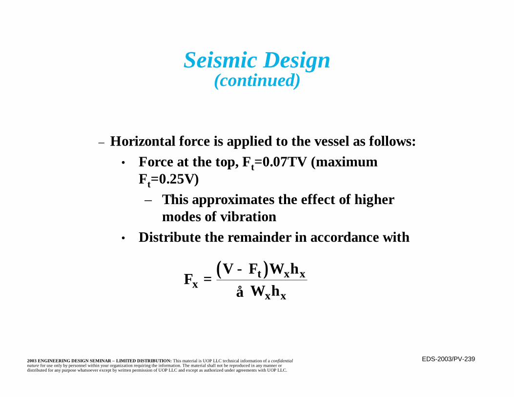
EDS-2003/PV-2392003 ENGINEERING DESIGN SEMINAR – LIMITED DISTRIBUTION: This material is UOP LLC technical information of a confidentialnature for use only by personnel within your organization requiring the information. The material shall not be reproduced in any manner ordistributed for any purpose whatsoever except by written permission of UOP LLC and except as authorized under agreements with UOP LLC.
– Horizontal force is applied to the vessel as follows:• Force at the top, Ft=0.07TV (maximum
Ft=0.25V)– This approximates the effect of higher
modes of vibration• Distribute the remainder in accordance with
( )FV F W h
W hxt x x
x x= −
∑
Seismic Design(continued)
EDS-2003/PV-2402003 ENGINEERING DESIGN SEMINAR – LIMITED DISTRIBUTION: This material is UOP LLC technical information of a confidentialnature for use only by personnel within your organization requiring the information. The material shall not be reproduced in any manner ordistributed for any purpose whatsoever except by written permission of UOP LLC and except as authorized under agreements with UOP LLC.
Seismic Design(continued)
– Horizontal force distribution is a function ofthe amount of mass at and the height of eachlocation
– For a vessel with uniform mass distribution,the force distribution becomes triangular
• The entire force (V-Ft) may be applied at2/3 the height

EDS-2003/PV-2412003 ENGINEERING DESIGN SEMINAR – LIMITED DISTRIBUTION: This material is UOP LLC technical information of a confidentialnature for use only by personnel within your organization requiring the information. The material shall not be reproduced in any manner ordistributed for any purpose whatsoever except by written permission of UOP LLC and except as authorized under agreements with UOP LLC.
n Additional Points– Movement or “sloshing” of liquid contents must be
accounted for– In general, use of the static force method has been
adequate• However, design for force resistance leads to use
of a stiffer structure, when more flexiblestructures are preferred for seismic conditions.
– If support is at intermediate point along vessel, treatportions above and below support separately
• Unlike wind loadings, the upper and lowerportions can move in opposite directions duringseismic activity
Seismic Design(continued)
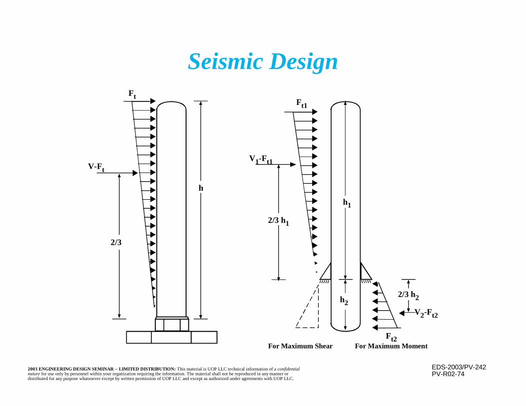
EDS-2003/PV-2422003 ENGINEERING DESIGN SEMINAR – LIMITED DISTRIBUTION: This material is UOP LLC technical information of a confidentialnature for use only by personnel within your organization requiring the information. The material shall not be reproduced in any manner ordistributed for any purpose whatsoever except by written permission of UOP LLC and except as authorized under agreements with UOP LLC.
PV-R02-74
Seismic Design
h
2/3 h
V-Ft
FtFt1
2/3 h1
V1-Ft1
h1
h2
Ft2
V2-Ft2
2/3 h2
For Maximum Shear For Maximum Moment
EDS-2003/PP-12003 ENGINEERING DESIGN SEMINAR – LIMITED DISTRIBUTION: This material is UOP LLC technical information of a confidentialnature for use only by personnel within your organization requiring the information. The material shall not be reproduced in any manner ordistributed for any purpose whatsoever except by written permission of UOP LLC and except as authorized under agreements with UOP LLC.
Piping
Training Services

EDS-2003/PP-22003 ENGINEERING DESIGN SEMINAR – LIMITED DISTRIBUTION: This material is UOP LLC technical information of a confidentialnature for use only by personnel within your organization requiring the information. The material shall not be reproduced in any manner ordistributed for any purpose whatsoever except by written permission of UOP LLC and except as authorized under agreements with UOP LLC.
To introduce piping designation, design,and support, including accommodationof thermal growth.
Purpose
EDS-2003/PP-32003 ENGINEERING DESIGN SEMINAR – LIMITED DISTRIBUTION: This material is UOP LLC technical information of a confidentialnature for use only by personnel within your organization requiring the information. The material shall not be reproduced in any manner ordistributed for any purpose whatsoever except by written permission of UOP LLC and except as authorized under agreements with UOP LLC.
Piping Definition
Piping is an assembly of components,including pipe, valves, fittings, flangesand supports, used to convey, distributeor control fluid flows.

EDS-2003/PP-42003 ENGINEERING DESIGN SEMINAR – LIMITED DISTRIBUTION: This material is UOP LLC technical information of a confidentialnature for use only by personnel within your organization requiring the information. The material shall not be reproduced in any manner ordistributed for any purpose whatsoever except by written permission of UOP LLC and except as authorized under agreements with UOP LLC.

EDS-2003/PP-52003 ENGINEERING DESIGN SEMINAR – LIMITED DISTRIBUTION: This material is UOP LLC technical information of a confidentialnature for use only by personnel within your organization requiring the information. The material shall not be reproduced in any manner ordistributed for any purpose whatsoever except by written permission of UOP LLC and except as authorized under agreements with UOP LLC.
Definitions
n Pipe– A hollow, generally cylindrical member used to
convey a wide range of fluids (gas, liquid, orfine solids) over a wide range of temperaturesand pressures
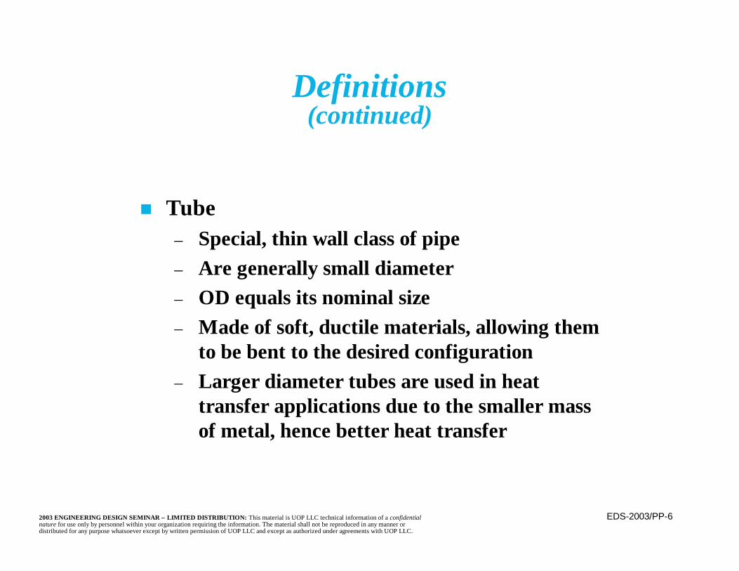
EDS-2003/PP-62003 ENGINEERING DESIGN SEMINAR – LIMITED DISTRIBUTION: This material is UOP LLC technical information of a confidentialnature for use only by personnel within your organization requiring the information. The material shall not be reproduced in any manner ordistributed for any purpose whatsoever except by written permission of UOP LLC and except as authorized under agreements with UOP LLC.
Definitions(continued)
n Tube– Special, thin wall class of pipe– Are generally small diameter– OD equals its nominal size– Made of soft, ductile materials, allowing them
to be bent to the desired configuration– Larger diameter tubes are used in heat
transfer applications due to the smaller massof metal, hence better heat transfer
EDS-2003/PP-72003 ENGINEERING DESIGN SEMINAR – LIMITED DISTRIBUTION: This material is UOP LLC technical information of a confidentialnature for use only by personnel within your organization requiring the information. The material shall not be reproduced in any manner ordistributed for any purpose whatsoever except by written permission of UOP LLC and except as authorized under agreements with UOP LLC.
Definitions(continued)
n Ducting– A thin wall, often rectangular system used to
convey vapor at near atmospheric pressure(i.e. a few inches of water).
EDS-2003/PP-82003 ENGINEERING DESIGN SEMINAR – LIMITED DISTRIBUTION: This material is UOP LLC technical information of a confidentialnature for use only by personnel within your organization requiring the information. The material shall not be reproduced in any manner ordistributed for any purpose whatsoever except by written permission of UOP LLC and except as authorized under agreements with UOP LLC.
Piping Designation
n Nominal pipe size (nps) is used to designatedpiping size
n For each pipe size, outside diameter is aconstant
– As wall thickness changes, the inside diameterand, therefore, the flowing area, varies
EDS-2003/PP-92003 ENGINEERING DESIGN SEMINAR – LIMITED DISTRIBUTION: This material is UOP LLC technical information of a confidentialnature for use only by personnel within your organization requiring the information. The material shall not be reproduced in any manner ordistributed for any purpose whatsoever except by written permission of UOP LLC and except as authorized under agreements with UOP LLC.
Piping Designation(continued)
n For 14 inches and above, the nps is equal tothe outside diameter
n For smaller sizes, the outside diameter varieswith the size
– For example, 10 inch pipe is 10.75 inches OD,6 inch pipe is 6.625 inches OD, and 2 inch pipeis 2.375 inches OD

EDS-2003/PP-102003 ENGINEERING DESIGN SEMINAR – LIMITED DISTRIBUTION: This material is UOP LLC technical information of a confidentialnature for use only by personnel within your organization requiring the information. The material shall not be reproduced in any manner ordistributed for any purpose whatsoever except by written permission of UOP LLC and except as authorized under agreements with UOP LLC.
Piping Thickness
n Piping is available in many standard thicknesses– Common thicknesses are designated as schedules
n Schedule 40 is “standard” thickness for npsthrough 10 inch
– For larger sizes, standard wall is 0.375 inch– In large diameter piping, sufficient thickness for
structural stability and handling is necessary
EDS-2003/PP-112003 ENGINEERING DESIGN SEMINAR – LIMITED DISTRIBUTION: This material is UOP LLC technical information of a confidentialnature for use only by personnel within your organization requiring the information. The material shall not be reproduced in any manner ordistributed for any purpose whatsoever except by written permission of UOP LLC and except as authorized under agreements with UOP LLC.
Piping Thickness(continued)
n Extra strong (X-strong) is another common size– Is the same as Schedule 80 through 10 inch nps– For larger sizes, it is 0.500 inch wall
n Double extra strong (XX-strong) is alsosometimes called for in smaller sizes
– Is available 1/2 inch through 8 inch nps (exceptfor 3.5 inch nps)
– Has twice the wall thickness of X-strong (exceptfor 8 inch nps)
EDS-2003/PP-122003 ENGINEERING DESIGN SEMINAR – LIMITED DISTRIBUTION: This material is UOP LLC technical information of a confidentialnature for use only by personnel within your organization requiring the information. The material shall not be reproduced in any manner ordistributed for any purpose whatsoever except by written permission of UOP LLC and except as authorized under agreements with UOP LLC.
Piping Thickness(continued)
n There is a ±12.5 percent manufacturingtolerance on wall thickness of seamless pipe
– Must be considered when determining requiredwall thickness, and when evaluating the crosssectional area of pipe wall and flowing area
n Small diameter pipe (1-1/2 inch and less) isusually a minimum of Schedule 80
n Pipe 2 - 10 inch uses Schedule 40 as minimumn Very large pipe must be thick enough for
stability and handling
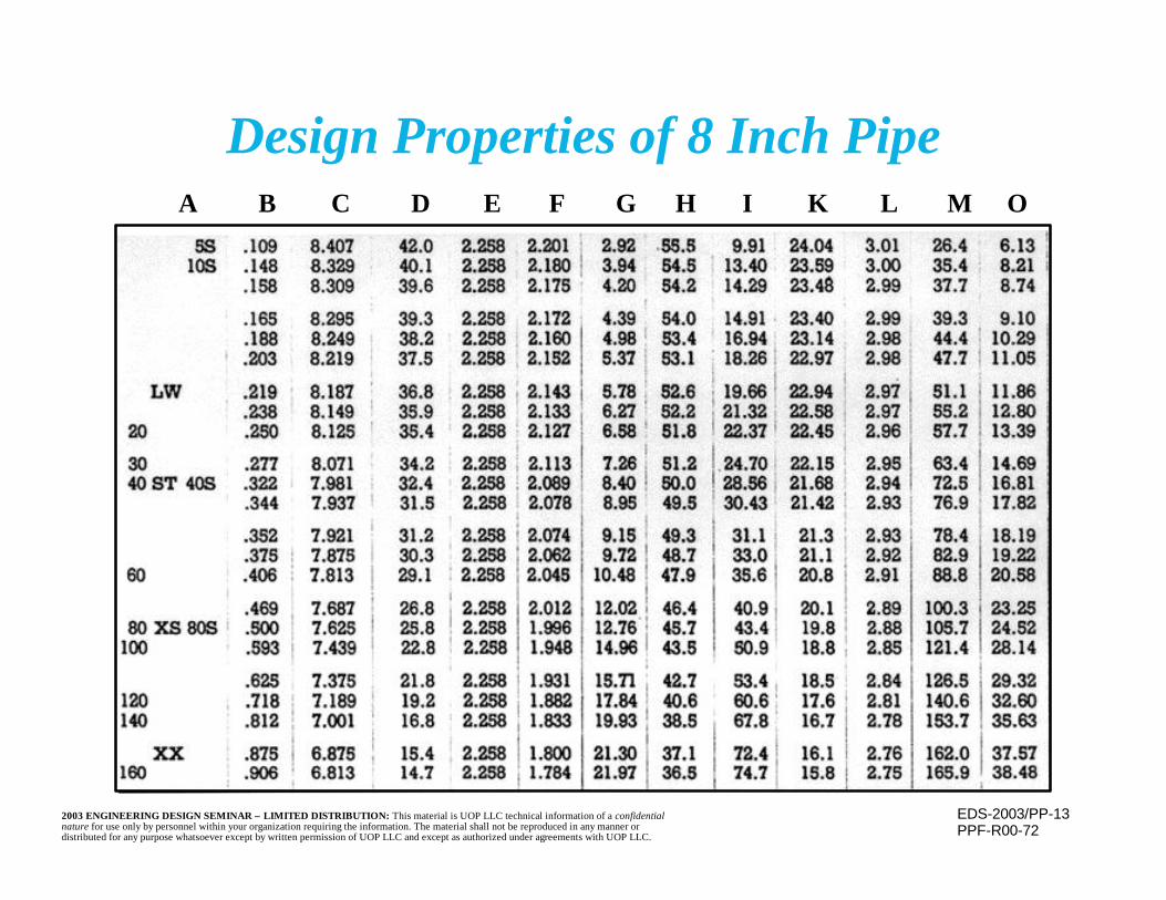
EDS-2003/PP-132003 ENGINEERING DESIGN SEMINAR – LIMITED DISTRIBUTION: This material is UOP LLC technical information of a confidentialnature for use only by personnel within your organization requiring the information. The material shall not be reproduced in any manner ordistributed for any purpose whatsoever except by written permission of UOP LLC and except as authorized under agreements with UOP LLC.
Design Properties of 8 Inch Pipe
PPF-R00-72
A B C D E F G H I K L M O
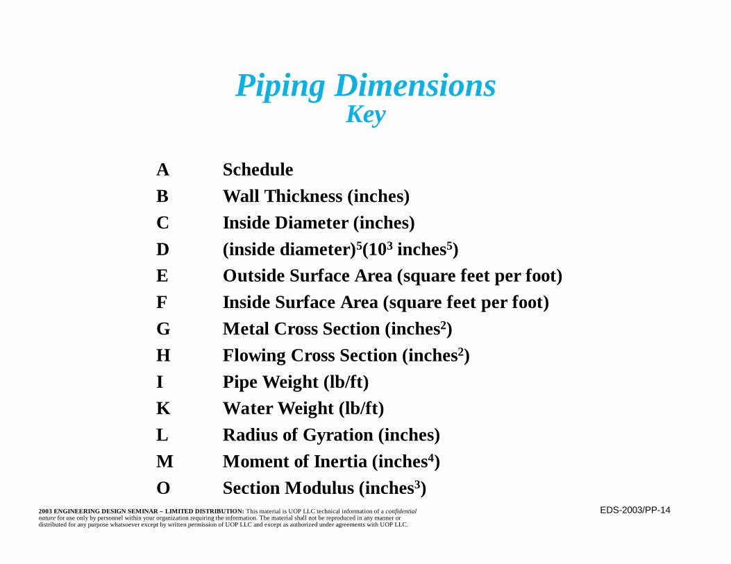
EDS-2003/PP-142003 ENGINEERING DESIGN SEMINAR – LIMITED DISTRIBUTION: This material is UOP LLC technical information of a confidentialnature for use only by personnel within your organization requiring the information. The material shall not be reproduced in any manner ordistributed for any purpose whatsoever except by written permission of UOP LLC and except as authorized under agreements with UOP LLC.
A ScheduleB Wall Thickness (inches)C Inside Diameter (inches)D (inside diameter)5(103 inches5)E Outside Surface Area (square feet per foot)F Inside Surface Area (square feet per foot)G Metal Cross Section (inches2)H Flowing Cross Section (inches2)I Pipe Weight (lb/ft)K Water Weight (lb/ft)L Radius of Gyration (inches)M Moment of Inertia (inches4)O Section Modulus (inches3)
Piping DimensionsKey
EDS-2003/PP-152003 ENGINEERING DESIGN SEMINAR – LIMITED DISTRIBUTION: This material is UOP LLC technical information of a confidentialnature for use only by personnel within your organization requiring the information. The material shall not be reproduced in any manner ordistributed for any purpose whatsoever except by written permission of UOP LLC and except as authorized under agreements with UOP LLC.
Piping Fittings
n Fittings are piping system components that providefor junctions, size changes, and terminations
– Examples are elbows, tees, caps, and reducers(eccentric and concentric)
n Fittings are made to standardized shapes and sizes– ASME B16.9, “Factory-Made Wrought Steel
Buttwelding Fittings” is the governing standard– ASME B16.28, “Wrought Steel Buttwelding Short
Radius Elbows and Returns” covers short radiuselbows
EDS-2003/PP-162003 ENGINEERING DESIGN SEMINAR – LIMITED DISTRIBUTION: This material is UOP LLC technical information of a confidentialnature for use only by personnel within your organization requiring the information. The material shall not be reproduced in any manner ordistributed for any purpose whatsoever except by written permission of UOP LLC and except as authorized under agreements with UOP LLC.
Piping Fittings(continued)
n Fittings are forged (wrought) components– May occasionally be fabricated or, in the case
of bends, made from bent pipen Elbows are available as long radius (bend
radius equals 1.5 times the nps) and shortradius (bend radius equals the nps)
– Long radius is standard because of smallerpressure drop and less potential for erosion
– Short radius elbows have the same pressurerating as straight seamless pipe
EDS-2003/PP-172003 ENGINEERING DESIGN SEMINAR – LIMITED DISTRIBUTION: This material is UOP LLC technical information of a confidentialnature for use only by personnel within your organization requiring the information. The material shall not be reproduced in any manner ordistributed for any purpose whatsoever except by written permission of UOP LLC and except as authorized under agreements with UOP LLC.
Piping Fittings(continued)
n For solids conveyance (e.g., catalyst) “sweep”elbows are often used
– Are very long radius, gentle, changes ofdirection to avoid breaking up the solids
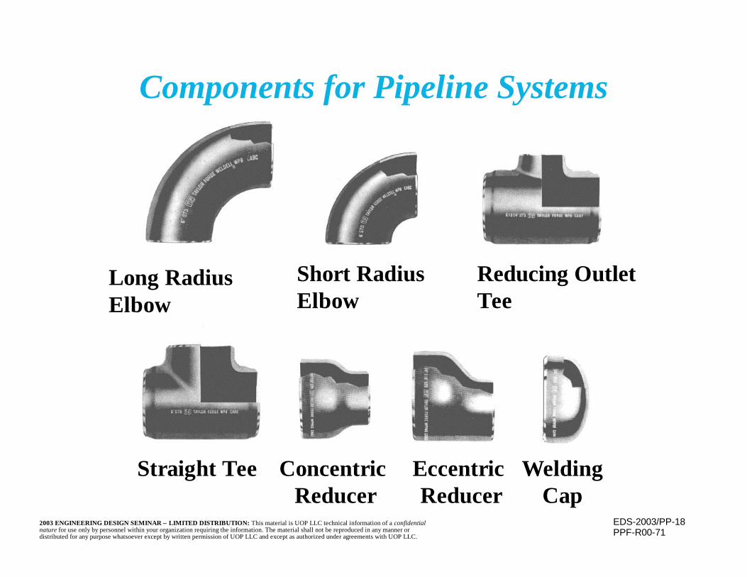
EDS-2003/PP-182003 ENGINEERING DESIGN SEMINAR – LIMITED DISTRIBUTION: This material is UOP LLC technical information of a confidentialnature for use only by personnel within your organization requiring the information. The material shall not be reproduced in any manner ordistributed for any purpose whatsoever except by written permission of UOP LLC and except as authorized under agreements with UOP LLC.
Components for Pipeline Systems
PPF-R00-71
Long RadiusElbow
Short RadiusElbow
Reducing OutletTee
Straight Tee Concentric Reducer
WeldingCap
Eccentric Reducer

EDS-2003/PP-192003 ENGINEERING DESIGN SEMINAR – LIMITED DISTRIBUTION: This material is UOP LLC technical information of a confidentialnature for use only by personnel within your organization requiring the information. The material shall not be reproduced in any manner ordistributed for any purpose whatsoever except by written permission of UOP LLC and except as authorized under agreements with UOP LLC.
Bending of Pipe
n Instead of using fittings for changes ofdirection, straight piping is occasionally bent
n Method is very common for small (2 inch andless) piping
n With proper controls, (e.g. maintenance ofcross section geometry, control of local strainsand thinning) larger piping may also be bent

EDS-2003/PP-202003 ENGINEERING DESIGN SEMINAR – LIMITED DISTRIBUTION: This material is UOP LLC technical information of a confidentialnature for use only by personnel within your organization requiring the information. The material shall not be reproduced in any manner ordistributed for any purpose whatsoever except by written permission of UOP LLC and except as authorized under agreements with UOP LLC.
Bending of Pipe(continued)
n Bending is normally done cold
n Hot bending may be considered if:– Procedure is tightly controlled and performed
by trained, experienced people with properequipment (e.g., not a welding torch)
– Temperatures, holds, and heating and coolingrates, as well as the transition from cold to hotpipe, are tightly controlled
EDS-2003/PP-212003 ENGINEERING DESIGN SEMINAR – LIMITED DISTRIBUTION: This material is UOP LLC technical information of a confidentialnature for use only by personnel within your organization requiring the information. The material shall not be reproduced in any manner ordistributed for any purpose whatsoever except by written permission of UOP LLC and except as authorized under agreements with UOP LLC.
Bending of Pipe(continued)
n Hot bending (continued)– Material must be suitable for the procedure
(i.e. metallurgical structure and mechanicalproperties maintained)
– Wall thinning or buckling, and cross sectiondistortion (e.g., ovaling and flattening) mustbe controlled
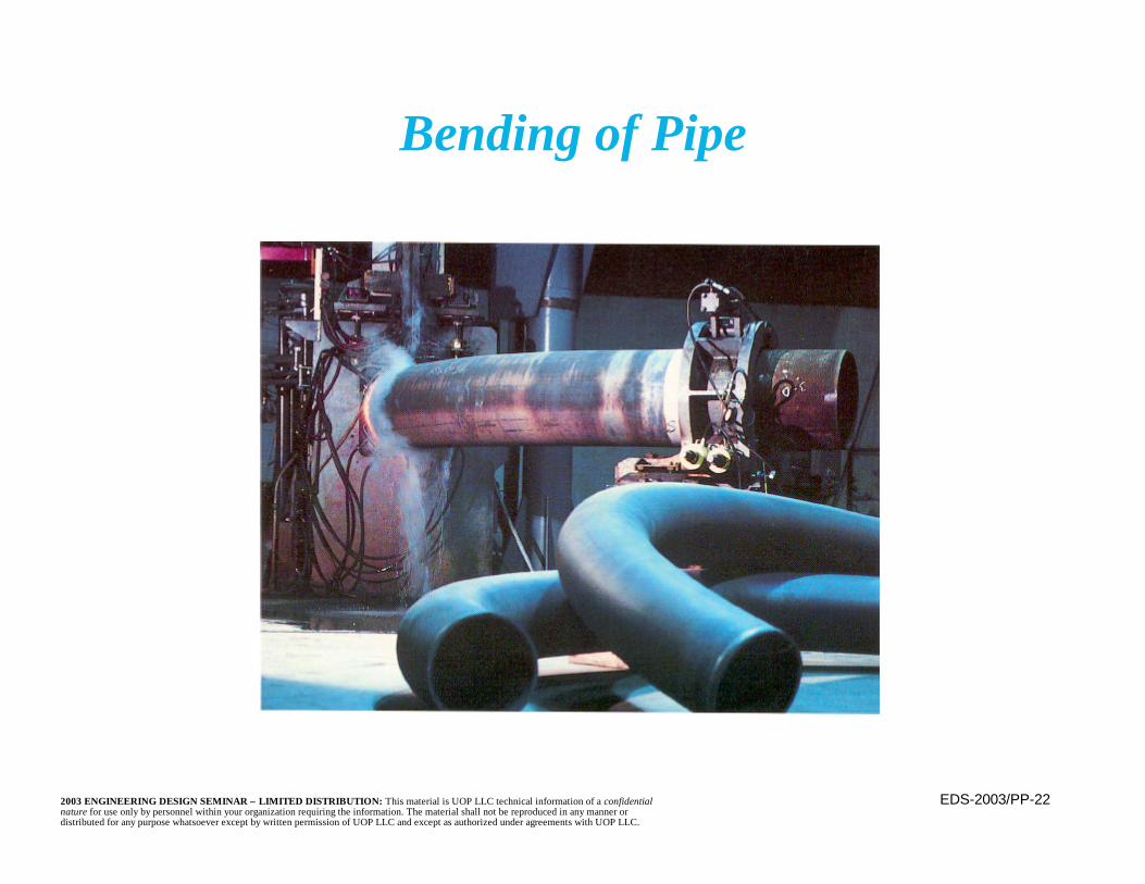
EDS-2003/PP-222003 ENGINEERING DESIGN SEMINAR – LIMITED DISTRIBUTION: This material is UOP LLC technical information of a confidentialnature for use only by personnel within your organization requiring the information. The material shall not be reproduced in any manner ordistributed for any purpose whatsoever except by written permission of UOP LLC and except as authorized under agreements with UOP LLC.
Bending of Pipe
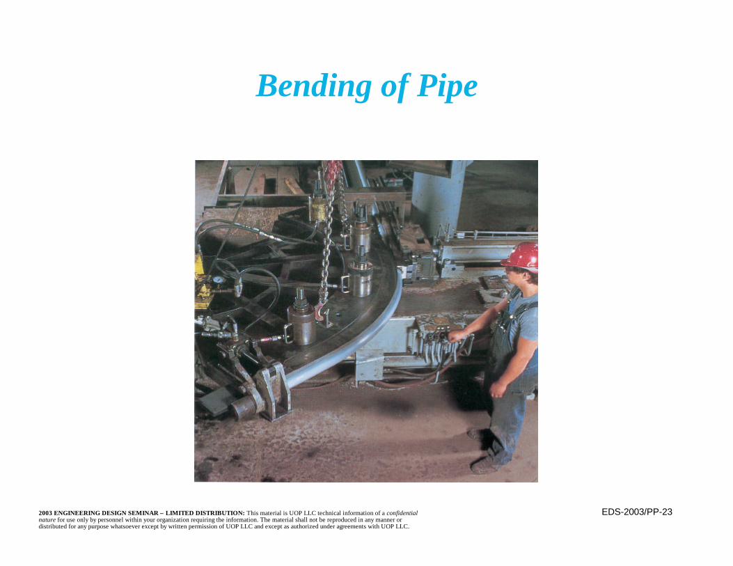
EDS-2003/PP-232003 ENGINEERING DESIGN SEMINAR – LIMITED DISTRIBUTION: This material is UOP LLC technical information of a confidentialnature for use only by personnel within your organization requiring the information. The material shall not be reproduced in any manner ordistributed for any purpose whatsoever except by written permission of UOP LLC and except as authorized under agreements with UOP LLC.
Bending of Pipe
EDS-2003/PP-242003 ENGINEERING DESIGN SEMINAR – LIMITED DISTRIBUTION: This material is UOP LLC technical information of a confidentialnature for use only by personnel within your organization requiring the information. The material shall not be reproduced in any manner ordistributed for any purpose whatsoever except by written permission of UOP LLC and except as authorized under agreements with UOP LLC.
Miters
n Are elbows fabricated from lengths ofstraight pipe
n Most commonly used for large diameterpiping, where fittings are expensive or notreadily available

EDS-2003/PP-252003 ENGINEERING DESIGN SEMINAR – LIMITED DISTRIBUTION: This material is UOP LLC technical information of a confidentialnature for use only by personnel within your organization requiring the information. The material shall not be reproduced in any manner ordistributed for any purpose whatsoever except by written permission of UOP LLC and except as authorized under agreements with UOP LLC.
Miters(continued)
n Piping Code rules for determining permissibleinternal pressure in a miter bend are applicableonly if the angle of each miter cut does not exceed22.5° (total change of direction = 45°)
n Required thickness for a miter with a given internalpressure is greater than for a straight pipe
– Actual thickness may be the same because of the useof standard pipe thickness, with a minimumdepending upon size

EDS-2003/PP-262003 ENGINEERING DESIGN SEMINAR – LIMITED DISTRIBUTION: This material is UOP LLC technical information of a confidentialnature for use only by personnel within your organization requiring the information. The material shall not be reproduced in any manner ordistributed for any purpose whatsoever except by written permission of UOP LLC and except as authorized under agreements with UOP LLC.
Multiple Miter Bend
PPF-R02-51
D
R1
M
α
αr2α/2
α/2
T

EDS-2003/PP-272003 ENGINEERING DESIGN SEMINAR – LIMITED DISTRIBUTION: This material is UOP LLC technical information of a confidentialnature for use only by personnel within your organization requiring the information. The material shall not be reproduced in any manner ordistributed for any purpose whatsoever except by written permission of UOP LLC and except as authorized under agreements with UOP LLC.
Piping is buttwelded together using fullpenetration welds. Small piping (11/2inch and less) is generally socket welded.
Joining of Piping
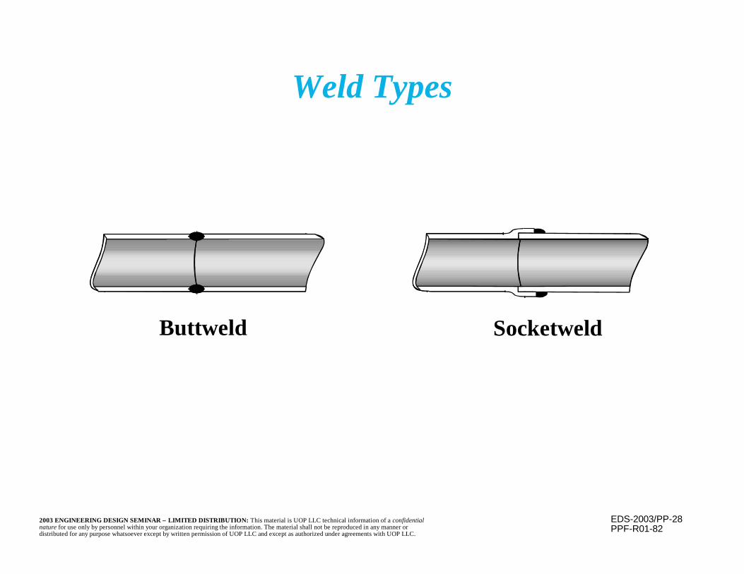
EDS-2003/PP-282003 ENGINEERING DESIGN SEMINAR – LIMITED DISTRIBUTION: This material is UOP LLC technical information of a confidentialnature for use only by personnel within your organization requiring the information. The material shall not be reproduced in any manner ordistributed for any purpose whatsoever except by written permission of UOP LLC and except as authorized under agreements with UOP LLC.
Buttweld Socketweld
Weld Types
PPF-R01-82
EDS-2003/PP-292003 ENGINEERING DESIGN SEMINAR – LIMITED DISTRIBUTION: This material is UOP LLC technical information of a confidentialnature for use only by personnel within your organization requiring the information. The material shall not be reproduced in any manner ordistributed for any purpose whatsoever except by written permission of UOP LLC and except as authorized under agreements with UOP LLC.
Piping Sizingn Process considerations are primary factor used to
determine required pipe sizesn Pressure drop through piping is the most common factor
in line sizing– Often expressed in “equivalent length” of straight pipe– Pressure drops of fittings, valves, reductions, etc., may be
expressed as an equivalent length of straight pipe– Convenient source of equivalent lengths is Crane
Company’s Technical Paper 410– The total pressure drop is found by multiplying the
equivalent length by the ?P per unit length of straight pipeof the appropriate size
– Pipe size is then selected for a low pressure drop, whileremaining economical
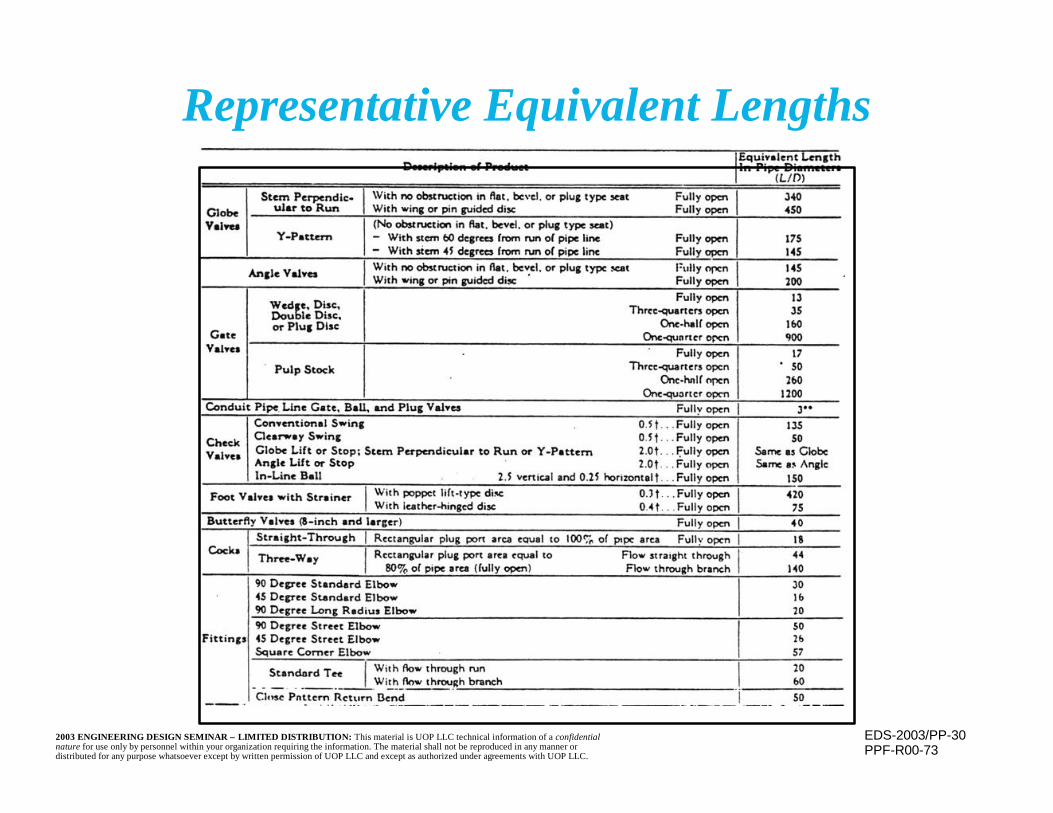
EDS-2003/PP-302003 ENGINEERING DESIGN SEMINAR – LIMITED DISTRIBUTION: This material is UOP LLC technical information of a confidentialnature for use only by personnel within your organization requiring the information. The material shall not be reproduced in any manner ordistributed for any purpose whatsoever except by written permission of UOP LLC and except as authorized under agreements with UOP LLC.
Representative Equivalent Lengths
PPF-R00-73
EDS-2003/PP-312003 ENGINEERING DESIGN SEMINAR – LIMITED DISTRIBUTION: This material is UOP LLC technical information of a confidentialnature for use only by personnel within your organization requiring the information. The material shall not be reproduced in any manner ordistributed for any purpose whatsoever except by written permission of UOP LLC and except as authorized under agreements with UOP LLC.
n Other factors that may affect line sizing:– Erosion potential of the carried medium (e.g.,
entrained solids) or the need to prevent settling ofcomponents of the flowing mixture
– Erosion reduction may call for low velocities andlarge diameter piping, while higher velocities toprevent settling argue for smaller diameter pipe
– In some cases velocity can affect the the corrosionrate of the base material by “stripping” off theprotective, passivating, film
Piping Sizing(continued)
EDS-2003/PP-322003 ENGINEERING DESIGN SEMINAR – LIMITED DISTRIBUTION: This material is UOP LLC technical information of a confidentialnature for use only by personnel within your organization requiring the information. The material shall not be reproduced in any manner ordistributed for any purpose whatsoever except by written permission of UOP LLC and except as authorized under agreements with UOP LLC.
Piping Sizing(continued)
n Piping is commercially available in sizes fromless than 1 inch to 60 inches or more.
n Through most of that range, pipe is availablein 2 inch increments (e.g., 6, 8, 10 inch).Beginning at 48 inches, the incrementincreases to 4 inches.
EDS-2003/PP-332003 ENGINEERING DESIGN SEMINAR – LIMITED DISTRIBUTION: This material is UOP LLC technical information of a confidentialnature for use only by personnel within your organization requiring the information. The material shall not be reproduced in any manner ordistributed for any purpose whatsoever except by written permission of UOP LLC and except as authorized under agreements with UOP LLC.
Piping Sizing(continued)
n When selecting a pipe size, consideration must begiven to availability of flanges, valves, fittings, etc.
n For this reason, some sizes are generally avoided– 2.5, 5, and 22 inch fall into this category
n Flanges are commonly available for 24 inch andsmaller piping. They conform to the requirementsof ASME B16.5. Flanges conforming to therequirements of ASME B16.47 are available forlarger piping (26 inches and greater).
EDS-2003/PP-342003 ENGINEERING DESIGN SEMINAR – LIMITED DISTRIBUTION: This material is UOP LLC technical information of a confidentialnature for use only by personnel within your organization requiring the information. The material shall not be reproduced in any manner ordistributed for any purpose whatsoever except by written permission of UOP LLC and except as authorized under agreements with UOP LLC.
Piping Sizing(continued)
n Minimum size normally used (other than forlocal instrument or utility lines) is 1 inch
n Small piping is provided as seamless (i.e., nolongitudinal seam), while piping over 14 - 16inches is normally welded (i.e., contains alongitudinal seam)
– Larger seamless piping is available, but isincreasingly more expensive as size increases

EDS-2003/PP-352003 ENGINEERING DESIGN SEMINAR – LIMITED DISTRIBUTION: This material is UOP LLC technical information of a confidentialnature for use only by personnel within your organization requiring the information. The material shall not be reproduced in any manner ordistributed for any purpose whatsoever except by written permission of UOP LLC and except as authorized under agreements with UOP LLC.
Valves
n Valves are integral part of any piping system– Used to regulate flow, halt flow, or prevent backflow
of fluids– Are also used for safety purposes to relieve pressure
n Valves must perform their intended functionwhenever they are called upon, whether that ismultiple times a day or after a long idle period
EDS-2003/PP-362003 ENGINEERING DESIGN SEMINAR – LIMITED DISTRIBUTION: This material is UOP LLC technical information of a confidentialnature for use only by personnel within your organization requiring the information. The material shall not be reproduced in any manner ordistributed for any purpose whatsoever except by written permission of UOP LLC and except as authorized under agreements with UOP LLC.
n Many types of valves, some very specialized
n Most common include gate, globe, check, ball,butterfly, relief valves
n Valve bodies are made to standard ratings,equivalent to the class rating system used forflanges
Valves(continued)

EDS-2003/PP-372003 ENGINEERING DESIGN SEMINAR – LIMITED DISTRIBUTION: This material is UOP LLC technical information of a confidentialnature for use only by personnel within your organization requiring the information. The material shall not be reproduced in any manner ordistributed for any purpose whatsoever except by written permission of UOP LLC and except as authorized under agreements with UOP LLC.
Gate ValveHandwheel
Yoke
Gland FlangeGlandStuffing BoxPacking
Body
Bonnet BushingStem
Bonnet
Disc Seat Rings
Disc
Body Seat Rings
PPF-R00-39
EDS-2003/PP-382003 ENGINEERING DESIGN SEMINAR – LIMITED DISTRIBUTION: This material is UOP LLC technical information of a confidentialnature for use only by personnel within your organization requiring the information. The material shall not be reproduced in any manner ordistributed for any purpose whatsoever except by written permission of UOP LLC and except as authorized under agreements with UOP LLC.
Gate Valves(continued)
n Most widely used valves in industrial plantsn Used to fully stop or fully permit flow
– Best used where infrequent operation is requiredn Not practical for throttling the flow because
flowing area is not a straight line function of theamount of the gate’s travel
– Is difficult to know how open or closed the valve is– Partially open gates set up vibrations that can
damage the valve
EDS-2003/PP-392003 ENGINEERING DESIGN SEMINAR – LIMITED DISTRIBUTION: This material is UOP LLC technical information of a confidentialnature for use only by personnel within your organization requiring the information. The material shall not be reproduced in any manner ordistributed for any purpose whatsoever except by written permission of UOP LLC and except as authorized under agreements with UOP LLC.
n Fluid passes straight through the valve,minimizing the pressure drop
n A plate slides up and down perpendicular tothe flow to open or close the flow path
– Usually takes many turns of the handwheel toopen or close valve
Gate Valves(continued)
EDS-2003/PP-402003 ENGINEERING DESIGN SEMINAR – LIMITED DISTRIBUTION: This material is UOP LLC technical information of a confidentialnature for use only by personnel within your organization requiring the information. The material shall not be reproduced in any manner ordistributed for any purpose whatsoever except by written permission of UOP LLC and except as authorized under agreements with UOP LLC.
n Most discs and seats have a matched taper,making repair or resurfacing difficult
n Stems may be rising or non rising– Screw surfaces on rising stems are isolated from
fluids in the line– A rising stem shows, at a glance, position of disc
(open or closed)– Clearance must be provided for the rising stem,
and exposed portions must be protected fromdamage or corrosion
– In non-rising stem system, screw threads areexposed to the corrosive fluid
Gate Valves(continued)
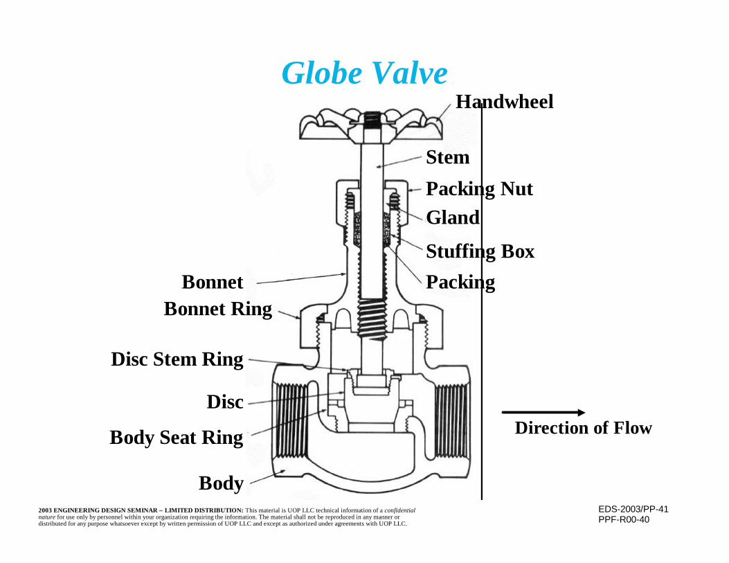
EDS-2003/PP-412003 ENGINEERING DESIGN SEMINAR – LIMITED DISTRIBUTION: This material is UOP LLC technical information of a confidentialnature for use only by personnel within your organization requiring the information. The material shall not be reproduced in any manner ordistributed for any purpose whatsoever except by written permission of UOP LLC and except as authorized under agreements with UOP LLC.
Globe ValveHandwheel
StemPacking NutGland
Stuffing BoxPackingBonnet
Bonnet Ring
Disc Stem Ring
Disc
Body Seat Ring
Body
PPF-R00-40
Direction of Flow

EDS-2003/PP-422003 ENGINEERING DESIGN SEMINAR – LIMITED DISTRIBUTION: This material is UOP LLC technical information of a confidentialnature for use only by personnel within your organization requiring the information. The material shall not be reproduced in any manner ordistributed for any purpose whatsoever except by written permission of UOP LLC and except as authorized under agreements with UOP LLC.
n Seat of a globe valve is parallel to the flowpath
– All contact between seat and disc ends whenflow begins
n Efficient for throttling of flow with minimumerosion
n Perform well where frequent operation isrequired
Globe Valves(continued)
EDS-2003/PP-432003 ENGINEERING DESIGN SEMINAR – LIMITED DISTRIBUTION: This material is UOP LLC technical information of a confidentialnature for use only by personnel within your organization requiring the information. The material shall not be reproduced in any manner ordistributed for any purpose whatsoever except by written permission of UOP LLC and except as authorized under agreements with UOP LLC.
n Size of seat opening is proportional to thenumber of handwheel turns, makingregulation of the flowing area easier
n Maintenance is easier than gate valves, oftenwithout removing the valve from the line
n Not recommended where flow resistance andpressure drop are a concern because flowpath is not straight
Globe Valves(continued)
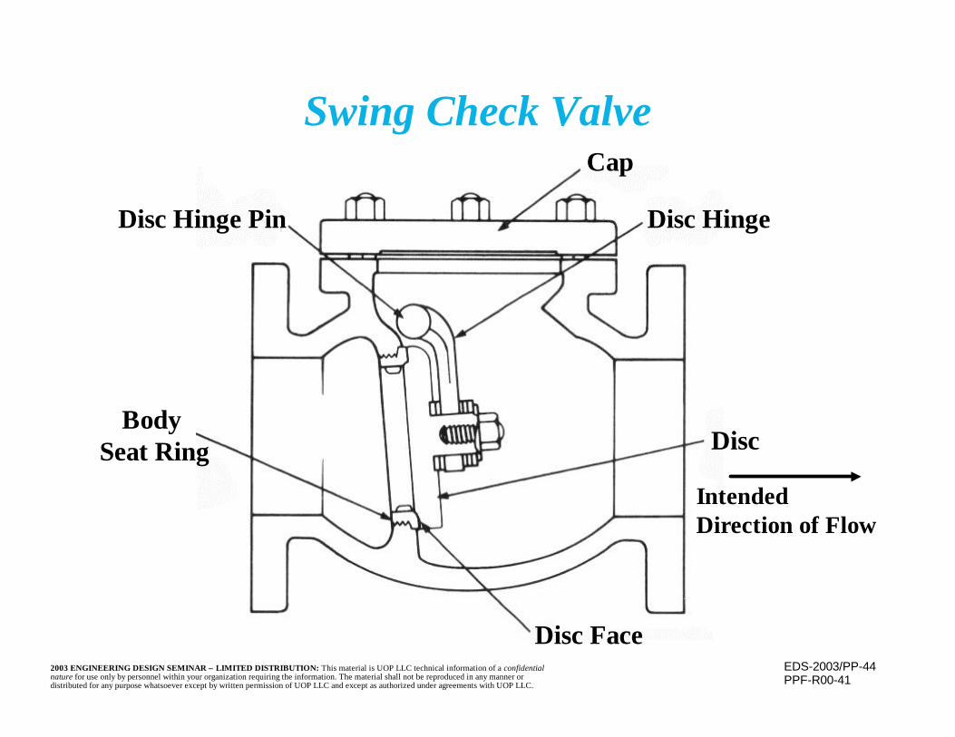
EDS-2003/PP-442003 ENGINEERING DESIGN SEMINAR – LIMITED DISTRIBUTION: This material is UOP LLC technical information of a confidentialnature for use only by personnel within your organization requiring the information. The material shall not be reproduced in any manner ordistributed for any purpose whatsoever except by written permission of UOP LLC and except as authorized under agreements with UOP LLC.
Swing Check ValveCap
Disc Hinge
Disc
Disc Face
Body Seat Ring
Disc Hinge Pin
PPF-R00-41
IntendedDirection of Flow
EDS-2003/PP-452003 ENGINEERING DESIGN SEMINAR – LIMITED DISTRIBUTION: This material is UOP LLC technical information of a confidentialnature for use only by personnel within your organization requiring the information. The material shall not be reproduced in any manner ordistributed for any purpose whatsoever except by written permission of UOP LLC and except as authorized under agreements with UOP LLC.
Check Valves
n Check valves prevent the backflow of thecarried fluid, i.e., they are “one way” valves
n The disc may be seated by gravity, by the fluiditself if it attempts to reverse, or sometimes by apiston or spring

EDS-2003/PP-462003 ENGINEERING DESIGN SEMINAR – LIMITED DISTRIBUTION: This material is UOP LLC technical information of a confidentialnature for use only by personnel within your organization requiring the information. The material shall not be reproduced in any manner ordistributed for any purpose whatsoever except by written permission of UOP LLC and except as authorized under agreements with UOP LLC.
n Swing check valves are the most common inliquid service
– Flow itself opens the valve, and keeps it open– Straight flow path means low pressure drop– Vapor usually has insufficient momentum to
keep the valve openn Lift checks are seated by gravity or the lack of
flow– For a horizontal line, the change of direction
results in increased pressure drop
Check Valves(continued)

EDS-2003/PP-472003 ENGINEERING DESIGN SEMINAR – LIMITED DISTRIBUTION: This material is UOP LLC technical information of a confidentialnature for use only by personnel within your organization requiring the information. The material shall not be reproduced in any manner ordistributed for any purpose whatsoever except by written permission of UOP LLC and except as authorized under agreements with UOP LLC.
Ball Valve
Spring
"Wedge-Seat"compensatesfor seat wear
Seat wipes ball clean,assuring tight shutoff
Top-Entry for maintenance
Lever Handle for quick quarter-turn
PPF-R00-42
EDS-2003/PP-482003 ENGINEERING DESIGN SEMINAR – LIMITED DISTRIBUTION: This material is UOP LLC technical information of a confidentialnature for use only by personnel within your organization requiring the information. The material shall not be reproduced in any manner ordistributed for any purpose whatsoever except by written permission of UOP LLC and except as authorized under agreements with UOP LLC.
Ball Valves (continued)
n Spring loaded ball, pierced with a line sizehole through the center
n Seat is always out of the flowing stream,between the ball and the valve body
– Can be good for flow carrying solids (preventsdamage to the seat)
n Flow path is straight through the valve,minimizing the pressure drop
EDS-2003/PP-492003 ENGINEERING DESIGN SEMINAR – LIMITED DISTRIBUTION: This material is UOP LLC technical information of a confidentialnature for use only by personnel within your organization requiring the information. The material shall not be reproduced in any manner ordistributed for any purpose whatsoever except by written permission of UOP LLC and except as authorized under agreements with UOP LLC.
n Valves open and close with a quarter turn of thehandle, making them quick on/off valves
n When installed in vertical piping, solids cansettle on the ball (especially when closed) and beground into the ball and seat upon use
n Are usually small so the force required to turnthe handle is manageable for one person
Ball Valves(continued)
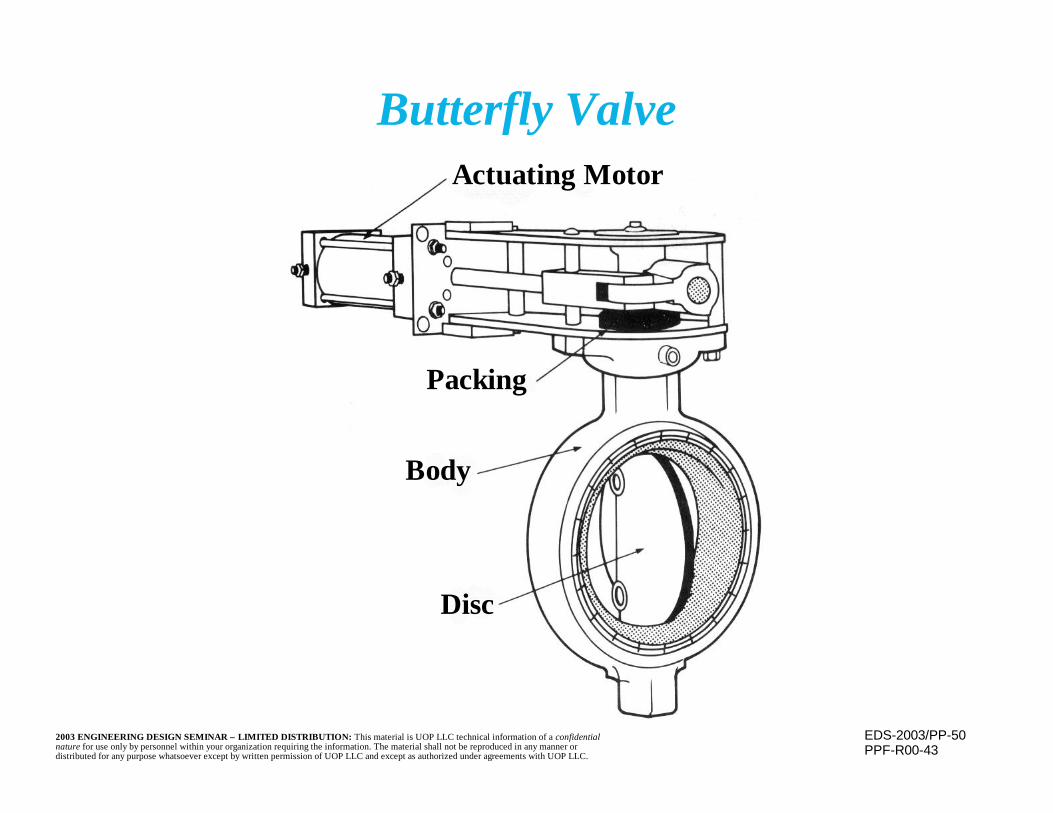
EDS-2003/PP-502003 ENGINEERING DESIGN SEMINAR – LIMITED DISTRIBUTION: This material is UOP LLC technical information of a confidentialnature for use only by personnel within your organization requiring the information. The material shall not be reproduced in any manner ordistributed for any purpose whatsoever except by written permission of UOP LLC and except as authorized under agreements with UOP LLC.
Butterfly ValveActuating Motor
Packing
Body
Disc
PPF-R00-43

EDS-2003/PP-512003 ENGINEERING DESIGN SEMINAR – LIMITED DISTRIBUTION: This material is UOP LLC technical information of a confidentialnature for use only by personnel within your organization requiring the information. The material shall not be reproduced in any manner ordistributed for any purpose whatsoever except by written permission of UOP LLC and except as authorized under agreements with UOP LLC.
Butterfly Valves (continued)
n Consists of a disc, a shaft, and a body
n Usually used with an actuator, though theycan be manual
n Used for flow control of gasses
n Not good for complete flow shut off– Another backup valve or, better, a blind
flange is required

EDS-2003/PP-522003 ENGINEERING DESIGN SEMINAR – LIMITED DISTRIBUTION: This material is UOP LLC technical information of a confidentialnature for use only by personnel within your organization requiring the information. The material shall not be reproduced in any manner ordistributed for any purpose whatsoever except by written permission of UOP LLC and except as authorized under agreements with UOP LLC.
Relief ValveAdjusting Bolt
Spring
Relief
Disc
Process Pressure
Seat Ring
Spindle
PPF-R00-44

EDS-2003/PP-532003 ENGINEERING DESIGN SEMINAR – LIMITED DISTRIBUTION: This material is UOP LLC technical information of a confidentialnature for use only by personnel within your organization requiring the information. The material shall not be reproduced in any manner ordistributed for any purpose whatsoever except by written permission of UOP LLC and except as authorized under agreements with UOP LLC.
Relief and Safety Valves
n Valves protect against overpressure of equipment– Overpressure could result in equipment damage
or failure, with possible catastrophic consequencesn One valve can protect a full system (several
pieces of equipment) if the system is “open”, i.e.,no valves or other means of isolation from therelief/safety valve
n Valves are rarely, if ever, used, but must reactquickly and properly when called upon, evenafter a long period of inactivity
EDS-2003/PP-542003 ENGINEERING DESIGN SEMINAR – LIMITED DISTRIBUTION: This material is UOP LLC technical information of a confidentialnature for use only by personnel within your organization requiring the information. The material shall not be reproduced in any manner ordistributed for any purpose whatsoever except by written permission of UOP LLC and except as authorized under agreements with UOP LLC.
Relief and Safety Valves(continued)
n Generally use a spring to remain sealed– If pressure rises, force on the disc becomes
greater than the spring force, causing the disc tolift and the contained fluid and pressure to vent
n Upon return to normal pressure, the springcauses the valve to reseat and seal
EDS-2003/PP-552003 ENGINEERING DESIGN SEMINAR – LIMITED DISTRIBUTION: This material is UOP LLC technical information of a confidentialnature for use only by personnel within your organization requiring the information. The material shall not be reproduced in any manner ordistributed for any purpose whatsoever except by written permission of UOP LLC and except as authorized under agreements with UOP LLC.
Relief and Safety Valves(continued)
n Safety valves are for use with compressiblefluids (gases) where a quick response is needed
– They open fully upon overpressure, relieving atfull flow
n Relief valves are for noncompressable fluidsand open more slowly
– They do not fully open immediately– Less fluid is lost upon relief
EDS-2003/PP-562003 ENGINEERING DESIGN SEMINAR – LIMITED DISTRIBUTION: This material is UOP LLC technical information of a confidentialnature for use only by personnel within your organization requiring the information. The material shall not be reproduced in any manner ordistributed for any purpose whatsoever except by written permission of UOP LLC and except as authorized under agreements with UOP LLC.
n Relief valves must be inspected and maintained toinsure that they function properly when needed
n Relief and safety valves must be installed close tothe equipment they protect so that pressure drop inthe piping to the valve is not a factor
n Backpressure (e.g. trapped liquid, relief systempressure) is not permitted because it is additive tothe spring force and will affect the pressure atwhich the valve opens
Relief and Safety Valves(continued)

EDS-2003/PP-572003 ENGINEERING DESIGN SEMINAR – LIMITED DISTRIBUTION: This material is UOP LLC technical information of a confidentialnature for use only by personnel within your organization requiring the information. The material shall not be reproduced in any manner ordistributed for any purpose whatsoever except by written permission of UOP LLC and except as authorized under agreements with UOP LLC.
n Pipe classes are a means of conveying allinformation necessary to specify thecomponents of a section of a piping system.
n Classes are usually organized based uponservice, metallurgy, flange class, corrosionallowance, and temperature
n Classes contain designation of the piping,component, and bolting material, gasketing,flange facing, valve details, minimum pipingthicknesses, etc.
Pipe Classes
EDS-2003/PP-582003 ENGINEERING DESIGN SEMINAR – LIMITED DISTRIBUTION: This material is UOP LLC technical information of a confidentialnature for use only by personnel within your organization requiring the information. The material shall not be reproduced in any manner ordistributed for any purpose whatsoever except by written permission of UOP LLC and except as authorized under agreements with UOP LLC.
n Contractors have prepared standardized classes– Special classes may be developed as needed
n Line indexes are prepared for each line of aspecific project
– They list the class, thickness, design temperatureand pressure, retirement thickness and otherdetails
Pipe Classes(continued)
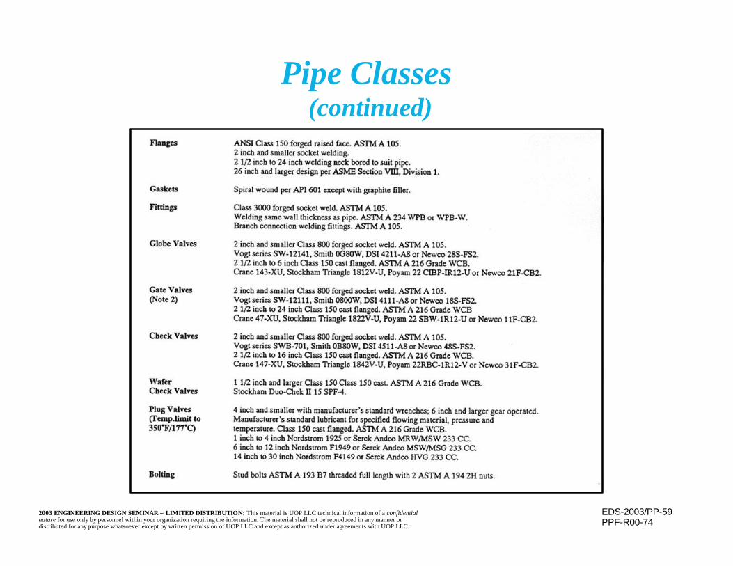
EDS-2003/PP-592003 ENGINEERING DESIGN SEMINAR – LIMITED DISTRIBUTION: This material is UOP LLC technical information of a confidentialnature for use only by personnel within your organization requiring the information. The material shall not be reproduced in any manner ordistributed for any purpose whatsoever except by written permission of UOP LLC and except as authorized under agreements with UOP LLC.
Pipe Classes (continued)
PPF-R00-74

EDS-2003/PP-602003 ENGINEERING DESIGN SEMINAR – LIMITED DISTRIBUTION: This material is UOP LLC technical information of a confidentialnature for use only by personnel within your organization requiring the information. The material shall not be reproduced in any manner ordistributed for any purpose whatsoever except by written permission of UOP LLC and except as authorized under agreements with UOP LLC.
n Most refinery and petrochemical piping isdesigned and fabricated in accordance withASME B31.3, “Process Piping”
– Is often referred to as the “Piping Code”
n Steam system piping is designed andfabricated in accordance with ASME B31.1,“Power Piping”
Piping Codes
EDS-2003/PP-612003 ENGINEERING DESIGN SEMINAR – LIMITED DISTRIBUTION: This material is UOP LLC technical information of a confidentialnature for use only by personnel within your organization requiring the information. The material shall not be reproduced in any manner ordistributed for any purpose whatsoever except by written permission of UOP LLC and except as authorized under agreements with UOP LLC.
n Pipe conforms to ASME B36.10M, “Welded and SeamlessWrought Steel Pipe” and ASME B36.19M, “Stainless SteelPipe”
n Material designations and requirements are in accordancewith American Society for Testing of Materials (ASTM)standards
n Existing pipe may be evaluated in accordance with ASMEB31G, “Manual for Determining the Remaining Strengthof Corroded Pipelines”
n Piping inspection guidelines are given in API 570, “PipingInspection Code: Inspection, Repair, Alteration, and Re-Rating of In-Service Piping Systems”
Piping Codes(continued)

EDS-2003/PP-622003 ENGINEERING DESIGN SEMINAR – LIMITED DISTRIBUTION: This material is UOP LLC technical information of a confidentialnature for use only by personnel within your organization requiring the information. The material shall not be reproduced in any manner ordistributed for any purpose whatsoever except by written permission of UOP LLC and except as authorized under agreements with UOP LLC.
n Code contains a listing of accepted standards
n A component that conforms to one of thesestandards, and that complies with that standard’stemperature and pressure ratings, may be usedwithout further evaluation
Pressure Design
EDS-2003/PP-632003 ENGINEERING DESIGN SEMINAR – LIMITED DISTRIBUTION: This material is UOP LLC technical information of a confidentialnature for use only by personnel within your organization requiring the information. The material shall not be reproduced in any manner ordistributed for any purpose whatsoever except by written permission of UOP LLC and except as authorized under agreements with UOP LLC.
n Components not in accordance with listedstandards, and proprietary items for whichCode rules are not applicable, shall be designedby rules consistent with Code philosophy
– Design shall be substantiated by serviceexperience under similar conditions, detailedstress analysis, or proof testing
n Other components (straight pipe, bends, miters,branches) may be designed by Code equations
Pressure Design(continued)
EDS-2003/PP-642003 ENGINEERING DESIGN SEMINAR – LIMITED DISTRIBUTION: This material is UOP LLC technical information of a confidentialnature for use only by personnel within your organization requiring the information. The material shall not be reproduced in any manner ordistributed for any purpose whatsoever except by written permission of UOP LLC and except as authorized under agreements with UOP LLC.
n Each component shall be designed for the mostsevere expected coincident pressure andtemperature condition
– Most severe condition is one resulting in thegreatest required thickness (piping) or highestrequired class (flanges, valves)
n Governing coincident conditions may not bethe highest or lowest pressure or temperature
Design Conditions

EDS-2003/PP-652003 ENGINEERING DESIGN SEMINAR – LIMITED DISTRIBUTION: This material is UOP LLC technical information of a confidentialnature for use only by personnel within your organization requiring the information. The material shall not be reproduced in any manner ordistributed for any purpose whatsoever except by written permission of UOP LLC and except as authorized under agreements with UOP LLC.
n Different components in same piping system maybe governed by different conditions
n Advantage may be taken of lower temperaturesof uninsulated components
– Temperature may be determined by test, heattransfer calculation, or Code guidelines
n Short term variations above design stress orrating are allowed if Code requirements are met
Design Conditions(continued)
EDS-2003/PP-662003 ENGINEERING DESIGN SEMINAR – LIMITED DISTRIBUTION: This material is UOP LLC technical information of a confidentialnature for use only by personnel within your organization requiring the information. The material shall not be reproduced in any manner ordistributed for any purpose whatsoever except by written permission of UOP LLC and except as authorized under agreements with UOP LLC.
n Piping Code explicitly permits a designtemperature reduction for uninsulatedpiping, valves, flanges and bolting
n Design temperature permitted, as apercentage of the fluid temperature:
Bolting - 80%Flanges - 90%Piping and Valves - 95%
Useful Piping Code Features
EDS-2003/PP-672003 ENGINEERING DESIGN SEMINAR – LIMITED DISTRIBUTION: This material is UOP LLC technical information of a confidentialnature for use only by personnel within your organization requiring the information. The material shall not be reproduced in any manner ordistributed for any purpose whatsoever except by written permission of UOP LLC and except as authorized under agreements with UOP LLC.
n Piping code also explicitly allows for occasionalshort-term variations above pressure-temperature design conditions if:
– Total number of variations is less than 1000– Pressure does not exceed test pressure or yield
strength at temperature, and– Non-ductile components are not present
Useful Piping Code Features(continued)

EDS-2003/PP-682003 ENGINEERING DESIGN SEMINAR – LIMITED DISTRIBUTION: This material is UOP LLC technical information of a confidentialnature for use only by personnel within your organization requiring the information. The material shall not be reproduced in any manner ordistributed for any purpose whatsoever except by written permission of UOP LLC and except as authorized under agreements with UOP LLC.
Useful Piping Code Features(continued)
n Stresses may exceed allowable by:– 33% - if no more than 10 hours at a time and
100 hours in a year– 20% - if no more than 50 hours at a time and
500 hours in a year
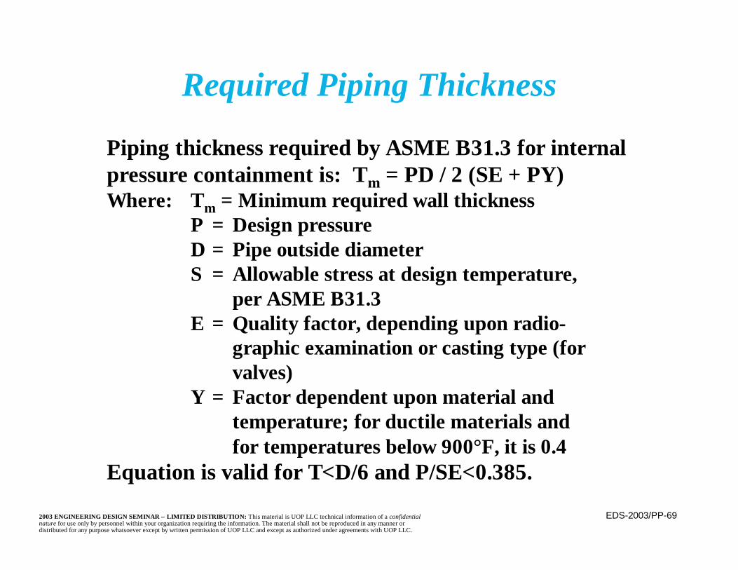
EDS-2003/PP-692003 ENGINEERING DESIGN SEMINAR – LIMITED DISTRIBUTION: This material is UOP LLC technical information of a confidentialnature for use only by personnel within your organization requiring the information. The material shall not be reproduced in any manner ordistributed for any purpose whatsoever except by written permission of UOP LLC and except as authorized under agreements with UOP LLC.
Piping thickness required by ASME B31.3 for internalpressure containment is: Tm = PD / 2 (SE + PY)Where: Tm = Minimum required wall thickness
P = Design pressureD = Pipe outside diameterS = Allowable stress at design temperature,
per ASME B31.3E = Quality factor, depending upon radio-
graphic examination or casting type (forvalves)
Y = Factor dependent upon material and temperature; for ductile materials and for temperatures below 900°F, it is 0.4
Equation is valid for T<D/6 and P/SE<0.385.
Required Piping Thickness
EDS-2003/PP-702003 ENGINEERING DESIGN SEMINAR – LIMITED DISTRIBUTION: This material is UOP LLC technical information of a confidentialnature for use only by personnel within your organization requiring the information. The material shall not be reproduced in any manner ordistributed for any purpose whatsoever except by written permission of UOP LLC and except as authorized under agreements with UOP LLC.
Required Piping Thickness(continued)
n Total thickness is the minimum requiredthickness plus the corrosion allowance,corrected to account for the 12.5% toleranceon thickness
– Standard schedule of pipe is then selected toprovide this thickness
n Pipe is then evaluated for any longitudinal orthermal loads
EDS-2003/PP-712003 ENGINEERING DESIGN SEMINAR – LIMITED DISTRIBUTION: This material is UOP LLC technical information of a confidentialnature for use only by personnel within your organization requiring the information. The material shall not be reproduced in any manner ordistributed for any purpose whatsoever except by written permission of UOP LLC and except as authorized under agreements with UOP LLC.
Required Piping Thickness(continued)
n Due to the normally small diameter andrelatively thick wall of piping, external pressureis usually not a concern
– When it is, use rules and procedures in PressureVessel Code
n Piping retirement thickness must be determined– One major factor in determining necessary
thickness is the thickness required by internalpressure and temperature
EDS-2003/PP-722003 ENGINEERING DESIGN SEMINAR – LIMITED DISTRIBUTION: This material is UOP LLC technical information of a confidentialnature for use only by personnel within your organization requiring the information. The material shall not be reproduced in any manner ordistributed for any purpose whatsoever except by written permission of UOP LLC and except as authorized under agreements with UOP LLC.
Basis for Allowable Stresses
n Piping Code allowable stresses are based upon thelowest of:
– One third of room temperature and operatingtemperature tensile strength
– Two thirds of room temperature and operatingtemperature yield strength
– Average stress for creep rate of 0.01% in 1000 hours– 67 percent of average stress for creep rupture in
100,000 hours– 80 percent of minimum stress for creep rupture in
100,000 hours
EDS-2003/PP-732003 ENGINEERING DESIGN SEMINAR – LIMITED DISTRIBUTION: This material is UOP LLC technical information of a confidentialnature for use only by personnel within your organization requiring the information. The material shall not be reproduced in any manner ordistributed for any purpose whatsoever except by written permission of UOP LLC and except as authorized under agreements with UOP LLC.
n Below the creep range, this criteria results inallowable stresses that are generally higherthan those permitted by Division 1 of thePressure Vessel Code
– Are more closely related to Division 2allowable range
n In the creep range, the allowable stress basisis the same as Division 1 of the PressureVessel Code
Basis for Allowable Stresses(continued)

EDS-2003/PP-742003 ENGINEERING DESIGN SEMINAR – LIMITED DISTRIBUTION: This material is UOP LLC technical information of a confidentialnature for use only by personnel within your organization requiring the information. The material shall not be reproduced in any manner ordistributed for any purpose whatsoever except by written permission of UOP LLC and except as authorized under agreements with UOP LLC.
Multiple Miter Bend
PPF-R02-51
D
R1
M
α
αr2α/2
α/2
T

EDS-2003/PP-752003 ENGINEERING DESIGN SEMINAR – LIMITED DISTRIBUTION: This material is UOP LLC technical information of a confidentialnature for use only by personnel within your organization requiring the information. The material shall not be reproduced in any manner ordistributed for any purpose whatsoever except by written permission of UOP LLC and except as authorized under agreements with UOP LLC.
n Per the Piping Code (B31.3), the allowableinternal pressure for a multiple bend miter isthe lessor of:
( ) ( )
( )
P SE T Cr
T CT C r T C
or
PSE T C
rR r
R r
m
m
= − −− + −
= − −−
( ). tan
.
2 2
2
1 2
1 2
0 643
0 5
θ
Miter Allowable Pressure
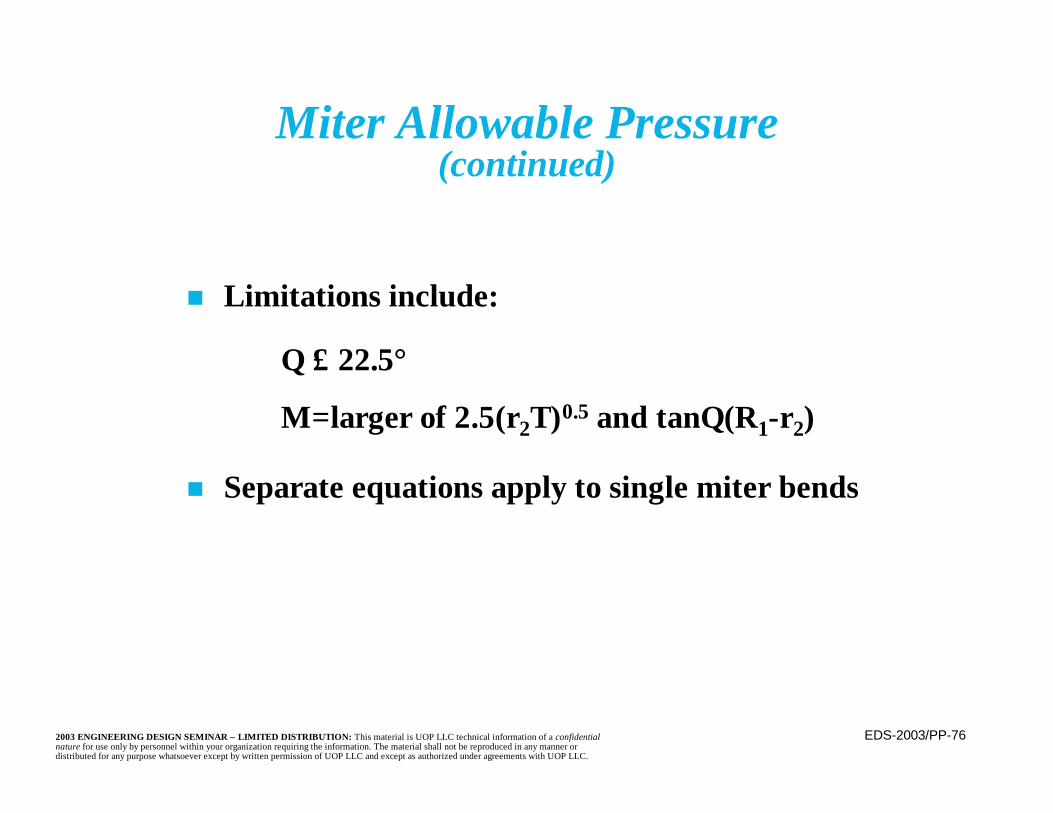
EDS-2003/PP-762003 ENGINEERING DESIGN SEMINAR – LIMITED DISTRIBUTION: This material is UOP LLC technical information of a confidentialnature for use only by personnel within your organization requiring the information. The material shall not be reproduced in any manner ordistributed for any purpose whatsoever except by written permission of UOP LLC and except as authorized under agreements with UOP LLC.
n Limitations include:
n Separate equations apply to single miter bends
Θ ≤ 22.5°
M=larger of 2.5(r2T)0.5 and tanΘ (R1-r2)
Miter Allowable Pressure(continued)
EDS-2003/PP-772003 ENGINEERING DESIGN SEMINAR – LIMITED DISTRIBUTION: This material is UOP LLC technical information of a confidentialnature for use only by personnel within your organization requiring the information. The material shall not be reproduced in any manner ordistributed for any purpose whatsoever except by written permission of UOP LLC and except as authorized under agreements with UOP LLC.
Branch Connections
n Junctions, or branch connections made with afitting (eg, a tee) complying with standard listedin the Piping Code may be used within its ratedpressure without evaluation
n Use of proprietary fittings, such as weldolets, isacceptable, provided they have been qualified byburst test requirements of the Code
– Be sure that they are fully and properly weldedn Branch junctions may be fabricated, but they
require an evaluation for adequate reinforcement– Area replacement method is used
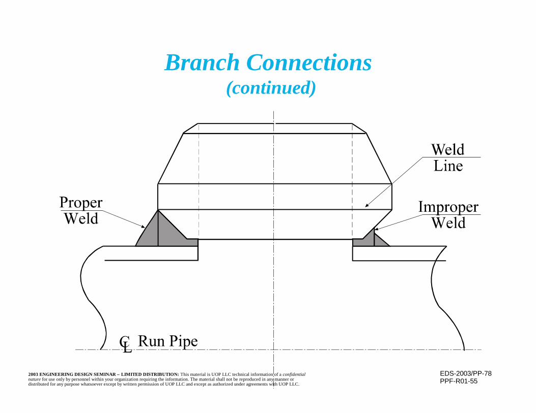
EDS-2003/PP-782003 ENGINEERING DESIGN SEMINAR – LIMITED DISTRIBUTION: This material is UOP LLC technical information of a confidentialnature for use only by personnel within your organization requiring the information. The material shall not be reproduced in any manner ordistributed for any purpose whatsoever except by written permission of UOP LLC and except as authorized under agreements with UOP LLC.
Branch Connections (continued)
PPF-R01-55
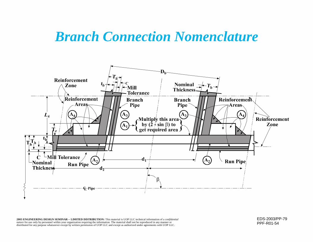
EDS-2003/PP-792003 ENGINEERING DESIGN SEMINAR – LIMITED DISTRIBUTION: This material is UOP LLC technical information of a confidentialnature for use only by personnel within your organization requiring the information. The material shall not be reproduced in any manner ordistributed for any purpose whatsoever except by written permission of UOP LLC and except as authorized under agreements with UOP LLC.
Branch Connection Nomenclature
PPF-R01-54

EDS-2003/PP-802003 ENGINEERING DESIGN SEMINAR – LIMITED DISTRIBUTION: This material is UOP LLC technical information of a confidentialnature for use only by personnel within your organization requiring the information. The material shall not be reproduced in any manner ordistributed for any purpose whatsoever except by written permission of UOP LLC and except as authorized under agreements with UOP LLC.
n Required reinforcement area, A1=thd1(2-sinβ)where:th = pressure design thickness of headerd1 = effective length removed from headerβ = small angle between header and branch
Branch Connection Reinforcement
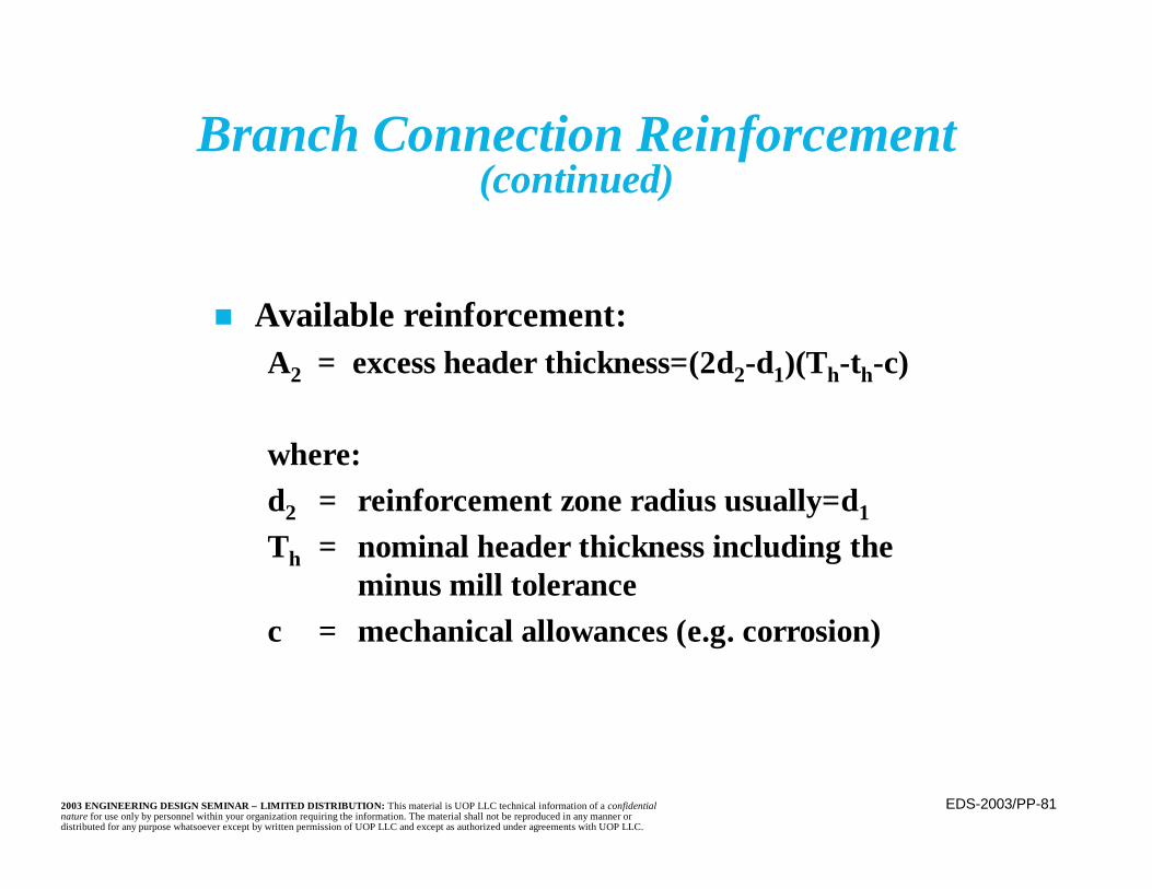
EDS-2003/PP-812003 ENGINEERING DESIGN SEMINAR – LIMITED DISTRIBUTION: This material is UOP LLC technical information of a confidentialnature for use only by personnel within your organization requiring the information. The material shall not be reproduced in any manner ordistributed for any purpose whatsoever except by written permission of UOP LLC and except as authorized under agreements with UOP LLC.
n Available reinforcement:A2 = excess header thickness=(2d2-d1)(Th-th-c)
where:d2 = reinforcement zone radius usually=d1
Th = nominal header thickness including the minus mill tolerance
c = mechanical allowances (e.g. corrosion)
Branch Connection Reinforcement(continued)
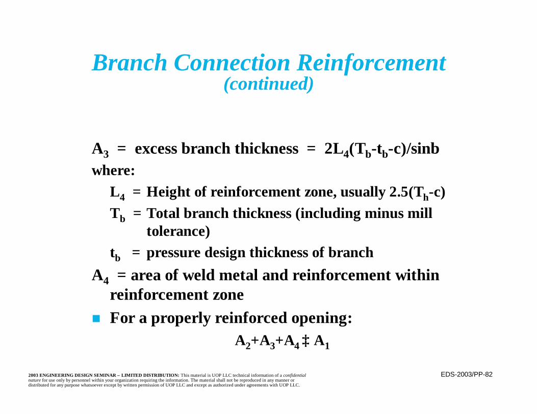
EDS-2003/PP-822003 ENGINEERING DESIGN SEMINAR – LIMITED DISTRIBUTION: This material is UOP LLC technical information of a confidentialnature for use only by personnel within your organization requiring the information. The material shall not be reproduced in any manner ordistributed for any purpose whatsoever except by written permission of UOP LLC and except as authorized under agreements with UOP LLC.
A3 = excess branch thickness = 2L4(Tb-tb-c)/sinβwhere:
L4 = Height of reinforcement zone, usually 2.5(Th-c)Tb = Total branch thickness (including minus mill
tolerance)tb = pressure design thickness of branch
A4 = area of weld metal and reinforcement withinreinforcement zone
n For a properly reinforced opening:A2+A3+A4 ≥ A1
Branch Connection Reinforcement(continued)
EDS-2003/PP-832003 ENGINEERING DESIGN SEMINAR – LIMITED DISTRIBUTION: This material is UOP LLC technical information of a confidentialnature for use only by personnel within your organization requiring the information. The material shall not be reproduced in any manner ordistributed for any purpose whatsoever except by written permission of UOP LLC and except as authorized under agreements with UOP LLC.
Branch Connections
n Extrusions may also be used for branchconnection points
n Extrusions are formed by pulling a diethrough the wall of the pipe, creating a radiusat the opening
– Radius reduces local stresses, and the joiningweld is a simple butt weld, located away fromany mechanical stress raisers
– Adequate reinforcement using areareplacement method must be present
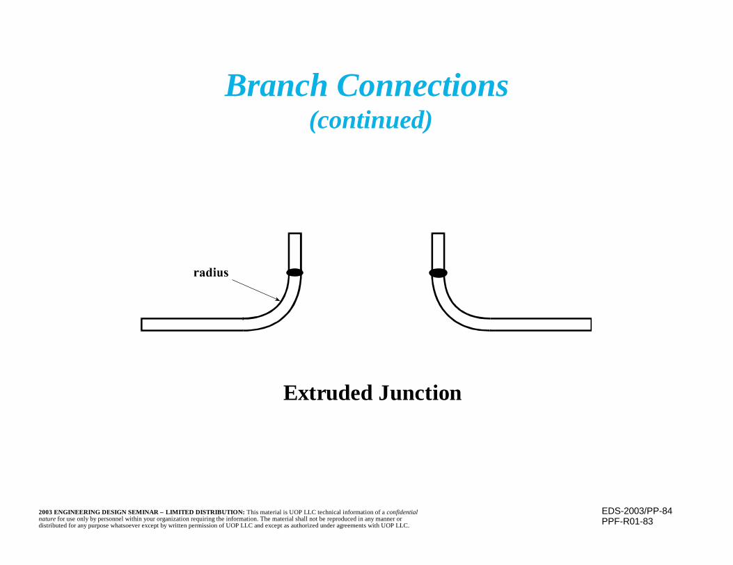
EDS-2003/PP-842003 ENGINEERING DESIGN SEMINAR – LIMITED DISTRIBUTION: This material is UOP LLC technical information of a confidentialnature for use only by personnel within your organization requiring the information. The material shall not be reproduced in any manner ordistributed for any purpose whatsoever except by written permission of UOP LLC and except as authorized under agreements with UOP LLC.
Branch Connections (continued)
Extruded Junction
PPF-R01-83
EDS-2003/PP-852003 ENGINEERING DESIGN SEMINAR – LIMITED DISTRIBUTION: This material is UOP LLC technical information of a confidentialnature for use only by personnel within your organization requiring the information. The material shall not be reproduced in any manner ordistributed for any purpose whatsoever except by written permission of UOP LLC and except as authorized under agreements with UOP LLC.
Piping Testing
n Piping Code requires that erected system bepressure tested
n Testing requirements are similar to thoserequired for pressure vessels, i.e., hydrostatic orpneumatic testing based upon design pressure
EDS-2003/PP-862003 ENGINEERING DESIGN SEMINAR – LIMITED DISTRIBUTION: This material is UOP LLC technical information of a confidentialnature for use only by personnel within your organization requiring the information. The material shall not be reproduced in any manner ordistributed for any purpose whatsoever except by written permission of UOP LLC and except as authorized under agreements with UOP LLC.
Piping Testing(continued)
n Hydrostatic Testing:– The Piping Code requires a test pressure of 1.5
times the design pressure times the ratio of cold tohot allowable stresses (SC/SH)
– The SC/SH ratio is “capped” at 6.5• Minimizes possibility of distortion or damage
during hydrotest from a high test pressurecaused by a low allowable stress due to creepconsiderations for elevated temperatureoperation

EDS-2003/PP-872003 ENGINEERING DESIGN SEMINAR – LIMITED DISTRIBUTION: This material is UOP LLC technical information of a confidentialnature for use only by personnel within your organization requiring the information. The material shall not be reproduced in any manner ordistributed for any purpose whatsoever except by written permission of UOP LLC and except as authorized under agreements with UOP LLC.
n Pneumatic Testing– The Piping Code requires a test pressure of 110 percent
of design pressure, without correction for cold vs. hotallowable stress
– This is due to the inherent danger from the storedenergy during a pneumatic test
– The initial test is normally performed at 25psig andgradually increased to the final test pressure (110percent of design)
Piping Testing(continued)
EDS-2003/PP-882003 ENGINEERING DESIGN SEMINAR – LIMITED DISTRIBUTION: This material is UOP LLC technical information of a confidentialnature for use only by personnel within your organization requiring the information. The material shall not be reproduced in any manner ordistributed for any purpose whatsoever except by written permission of UOP LLC and except as authorized under agreements with UOP LLC.
Piping Testing(continued)
n Nondestructive Examination– In certain circumstances (e.g., water exposure
is undesirable and pneumatic testing undulyhazardous), Piping Code, unlike the PressureVessel Code, also permits nondestructiveexamination plus a leak test instead of fullpressure testing
EDS-2003/PP-892003 ENGINEERING DESIGN SEMINAR – LIMITED DISTRIBUTION: This material is UOP LLC technical information of a confidentialnature for use only by personnel within your organization requiring the information. The material shall not be reproduced in any manner ordistributed for any purpose whatsoever except by written permission of UOP LLC and except as authorized under agreements with UOP LLC.
n During hydrotesting, care must be taken toinsure that system is adequately supported forthe additional weight of the water
n Flexible items, such as spring hangers, need to befixed into place to prevent excessive distortion(remember to remove the fixity before returningto service)
– Some components (e.g., expansion joint bellows,strainer internals) may need to be isolated fromthe test
Piping Testing(continued)
EDS-2003/PP-902003 ENGINEERING DESIGN SEMINAR – LIMITED DISTRIBUTION: This material is UOP LLC technical information of a confidentialnature for use only by personnel within your organization requiring the information. The material shall not be reproduced in any manner ordistributed for any purpose whatsoever except by written permission of UOP LLC and except as authorized under agreements with UOP LLC.
Piping Testing(continued)
n Additional pressure due to any head of waterpresent must be considered when testing apiping system
– May limit overall test pressure to avoidoverstress of portions of the piping
EDS-2003/PP-912003 ENGINEERING DESIGN SEMINAR – LIMITED DISTRIBUTION: This material is UOP LLC technical information of a confidentialnature for use only by personnel within your organization requiring the information. The material shall not be reproduced in any manner ordistributed for any purpose whatsoever except by written permission of UOP LLC and except as authorized under agreements with UOP LLC.
Cold Service Requirements
n Piping must be adequate for design minimumtemperature
– Temperature may be from cold service, auto-refrigeration, low ambient temperature, orother causes
n Minimum temperature at which each materialmay be used without further evaluation is listedin stress tables of the piping code
– -20°F is a common value– For some materials, reference is made to curves
similar to Pressure Vessel Code’s MDMT curves
EDS-2003/PP-922003 ENGINEERING DESIGN SEMINAR – LIMITED DISTRIBUTION: This material is UOP LLC technical information of a confidentialnature for use only by personnel within your organization requiring the information. The material shall not be reproduced in any manner ordistributed for any purpose whatsoever except by written permission of UOP LLC and except as authorized under agreements with UOP LLC.
Cold Service Requirements(continued)
n For colder temperatures, material must beCharpy V-notch impact tested, and meetlisted minimum impact capacity values,before it can be used.
n Alternatively, pretested materials, certified assuitable for a specified low temperature, maybe used without testing. These materials havepassed supplier performed Charpy V-notchimpact tests at the specified temperature.
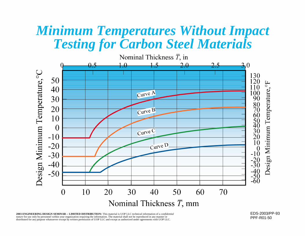
EDS-2003/PP-932003 ENGINEERING DESIGN SEMINAR – LIMITED DISTRIBUTION: This material is UOP LLC technical information of a confidentialnature for use only by personnel within your organization requiring the information. The material shall not be reproduced in any manner ordistributed for any purpose whatsoever except by written permission of UOP LLC and except as authorized under agreements with UOP LLC.
Minimum Temperatures Without ImpactTesting for Carbon Steel Materials
PPF-R01-50
EDS-2003/PP-942003 ENGINEERING DESIGN SEMINAR – LIMITED DISTRIBUTION: This material is UOP LLC technical information of a confidentialnature for use only by personnel within your organization requiring the information. The material shall not be reproduced in any manner ordistributed for any purpose whatsoever except by written permission of UOP LLC and except as authorized under agreements with UOP LLC.
Examination and Heat Treatment
n Process Piping Code contains requirements forpiping system assembly welding preheat andpostweld heat treatment
n Requirements are dependent upon materialcharacteristics
– Similar materials are grouped and assigned a “P”number, which is used to define the requirements

EDS-2003/PP-952003 ENGINEERING DESIGN SEMINAR – LIMITED DISTRIBUTION: This material is UOP LLC technical information of a confidentialnature for use only by personnel within your organization requiring the information. The material shall not be reproduced in any manner ordistributed for any purpose whatsoever except by written permission of UOP LLC and except as authorized under agreements with UOP LLC.
Examination and Heat Treatment(continued)
n Required examination of welds consists of visualinspection and a random radiograph or ultrasonicexamination of 5 percent of the butt welds of thecompleted system.– Further examination is as required by the piping
designn Heat treatment and examination of longitudinal welds are
as required by ASTM specification and class of pipingspecified. ASME B31.3 may impose additionalrequirements.
n For some materials and services UOP imposes additionalRadiography and heat treatment requirements.
EDS-2003/PP-962003 ENGINEERING DESIGN SEMINAR – LIMITED DISTRIBUTION: This material is UOP LLC technical information of a confidentialnature for use only by personnel within your organization requiring the information. The material shall not be reproduced in any manner ordistributed for any purpose whatsoever except by written permission of UOP LLC and except as authorized under agreements with UOP LLC.
Piping Flexibility
n Piping will be subject to thermal expansion(or contraction) caused by its own heating (orcooling) or that of the items to which it isconnected
n Piping must be able to accommodate thismovement without failure, overstress, flangeleakage, or overloading the items to which itis connected
EDS-2003/PP-972003 ENGINEERING DESIGN SEMINAR – LIMITED DISTRIBUTION: This material is UOP LLC technical information of a confidentialnature for use only by personnel within your organization requiring the information. The material shall not be reproduced in any manner ordistributed for any purpose whatsoever except by written permission of UOP LLC and except as authorized under agreements with UOP LLC.
Piping Flexibility(continued)
n Accommodation of the movements is a job fora specialist
n Encompasses plant layout, routing of thepiping and methods of supporting the piping
n Specialized computer programs are used toanalyze the system
n Flexibility is strain, not stress, driven
EDS-2003/PP-982003 ENGINEERING DESIGN SEMINAR – LIMITED DISTRIBUTION: This material is UOP LLC technical information of a confidentialnature for use only by personnel within your organization requiring the information. The material shall not be reproduced in any manner ordistributed for any purpose whatsoever except by written permission of UOP LLC and except as authorized under agreements with UOP LLC.
n Object is to avoid:– Failure of piping or components due to overstress
or fatigue– Leakage at joints– Detrimental stress or distortion in piping, valves,
or connected equipment (e.g. pumps, turbines,expanders)
– Creation of “pockets” (unvented or drained highor low spots), loss of required free draining, etc
Piping Flexibility(continued)

EDS-2003/PP-992003 ENGINEERING DESIGN SEMINAR – LIMITED DISTRIBUTION: This material is UOP LLC technical information of a confidentialnature for use only by personnel within your organization requiring the information. The material shall not be reproduced in any manner ordistributed for any purpose whatsoever except by written permission of UOP LLC and except as authorized under agreements with UOP LLC.
n In addition to thermal expansion and supportof the piping’s weight, wind, earthquake,vibration, dynamic loading, and friction mustbe considered
n Analysis usually considers three cases:– Sustained (force driven) loads only– Displacement (thermal loads) and movements
only– Operating case for reactions at equipment
Piping Flexibility(continued)
EDS-2003/PP-1002003 ENGINEERING DESIGN SEMINAR – LIMITED DISTRIBUTION: This material is UOP LLC technical information of a confidentialnature for use only by personnel within your organization requiring the information. The material shall not be reproduced in any manner ordistributed for any purpose whatsoever except by written permission of UOP LLC and except as authorized under agreements with UOP LLC.
Piping Flexibility(continued)
n Stress concentrations at elbows and otherpoints must be considered
n Piping Code contains stress intensificationfactors for determining effective stress atthese points

EDS-2003/PP-1012003 ENGINEERING DESIGN SEMINAR – LIMITED DISTRIBUTION: This material is UOP LLC technical information of a confidentialnature for use only by personnel within your organization requiring the information. The material shall not be reproduced in any manner ordistributed for any purpose whatsoever except by written permission of UOP LLC and except as authorized under agreements with UOP LLC.
Flexibility and Stress Intensification Factors
PPF-R02-52
cot θ Ts
2 r22
Description
Welding elbow orpipe bend
Closely spaced miter bends < r2 (1 + tan θ)
Single miter bend orwidely spaced miter bends > r2 (1 + tan θ)
FlexibilityFactor
k
θ
sr2
T
R1s cot θ
2=
r2
R1= bend radius
T
r2
T
R1r2 (1 + cot θ)
2=θ
s
Outplaneio
Inplaneii
FlexibilityCharacteristic
hSketch
1.65h
0.75h2/3
0.9h2/3
T R1
r22
1.52h5/6
0.9h2/3
0.9h2/3
1 + cot θ T
2 r2
1.52h5/6
0.9h2/3
0.9h2/3
Stress Intensification Factor

EDS-2003/PP-1022003 ENGINEERING DESIGN SEMINAR – LIMITED DISTRIBUTION: This material is UOP LLC technical information of a confidentialnature for use only by personnel within your organization requiring the information. The material shall not be reproduced in any manner ordistributed for any purpose whatsoever except by written permission of UOP LLC and except as authorized under agreements with UOP LLC.
n Analysis is based upon operating temperatureto properly account for all interactions andmovements of lines and equipment
n Review the entire system— not just oneline— because all portions are interrelated
– Response and stresses depend on the otherportions
Piping Flexibility(continued)

EDS-2003/PP-1032003 ENGINEERING DESIGN SEMINAR – LIMITED DISTRIBUTION: This material is UOP LLC technical information of a confidentialnature for use only by personnel within your organization requiring the information. The material shall not be reproduced in any manner ordistributed for any purpose whatsoever except by written permission of UOP LLC and except as authorized under agreements with UOP LLC.
Sustained and Displacement Stresseswhen Pipe Lifts off of Support
PPF-R01-36
EDS-2003/PP-1042003 ENGINEERING DESIGN SEMINAR – LIMITED DISTRIBUTION: This material is UOP LLC technical information of a confidentialnature for use only by personnel within your organization requiring the information. The material shall not be reproduced in any manner ordistributed for any purpose whatsoever except by written permission of UOP LLC and except as authorized under agreements with UOP LLC.
n Sustained load only case considers weight of theuncorroded piping, including contents, valves andattachments and longitudinal stresses due topressure
n Also includes other force driven loads, e.g., wind,earthquake, friction, etc
n Use nominal thickness in the corroded conditionfor determining stresses
n Is no thermal movement; therefore, flexibility (i.e.,moment of inertia) is not a factor
Piping Flexibility(continued)

EDS-2003/PP-1052003 ENGINEERING DESIGN SEMINAR – LIMITED DISTRIBUTION: This material is UOP LLC technical information of a confidentialnature for use only by personnel within your organization requiring the information. The material shall not be reproduced in any manner ordistributed for any purpose whatsoever except by written permission of UOP LLC and except as authorized under agreements with UOP LLC.
Piping Flexibility(continued)
n Allowable stress for the weight case is the hotallowable stress listed in the Piping Code,without a joint efficiency factor
n A 33% increase may be used when consideringwind or earthquake loadings
EDS-2003/PP-1062003 ENGINEERING DESIGN SEMINAR – LIMITED DISTRIBUTION: This material is UOP LLC technical information of a confidentialnature for use only by personnel within your organization requiring the information. The material shall not be reproduced in any manner ordistributed for any purpose whatsoever except by written permission of UOP LLC and except as authorized under agreements with UOP LLC.
Piping Flexibility(continued)
n For displacement, or strain driven, cases onlythe forces and loads resulting from the imposeddisplacements, such as thermal growth, areconsidered
n Consideration of multiple cases (e.g., startup,shutdown, operation, steamout, etc.) may benecessary in order to cover all possiblecombinations of temperatures for portions ofthe piping
– Piping weight is not included
EDS-2003/PP-1072003 ENGINEERING DESIGN SEMINAR – LIMITED DISTRIBUTION: This material is UOP LLC technical information of a confidentialnature for use only by personnel within your organization requiring the information. The material shall not be reproduced in any manner ordistributed for any purpose whatsoever except by written permission of UOP LLC and except as authorized under agreements with UOP LLC.
Piping Flexibility(continued)
n Use nominal (uncorroded) thickness and theambient temperature modulus of elasticity formaximum stiffness, hence highest displacementloads
n Thermal expansion is determined from thematerial’s thermal expansion coefficient, theoperating temperature, and lengths of pipe ateach temperature
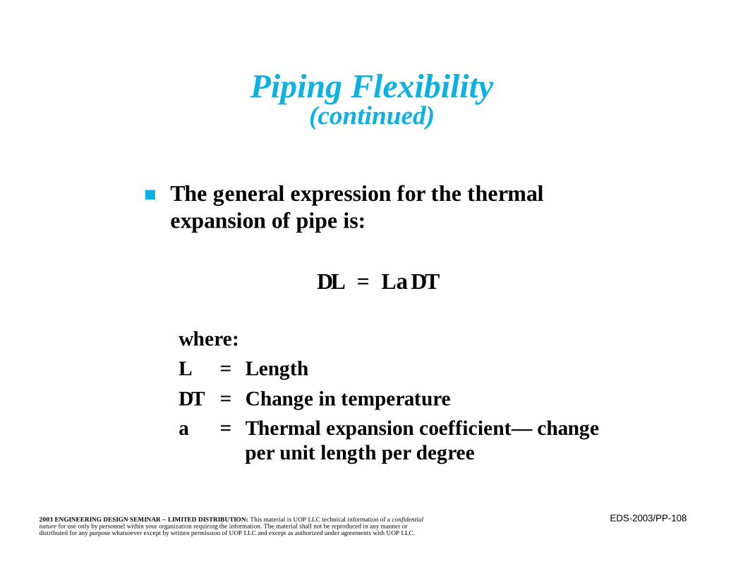
EDS-2003/PP-1082003 ENGINEERING DESIGN SEMINAR – LIMITED DISTRIBUTION: This material is UOP LLC technical information of a confidentialnature for use only by personnel within your organization requiring the information. The material shall not be reproduced in any manner ordistributed for any purpose whatsoever except by written permission of UOP LLC and except as authorized under agreements with UOP LLC.
Piping Flexibility(continued)
n The general expression for the thermalexpansion of pipe is:
∆L = Lα∆T
where:L = Length∆T = Change in temperatureα = Thermal expansion coefficient— change
per unit length per degree
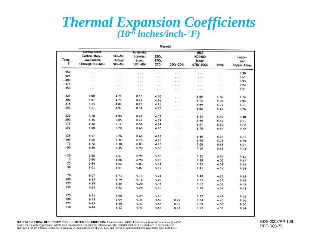
EDS-2003/PP-1092003 ENGINEERING DESIGN SEMINAR – LIMITED DISTRIBUTION: This material is UOP LLC technical information of a confidentialnature for use only by personnel within your organization requiring the information. The material shall not be reproduced in any manner ordistributed for any purpose whatsoever except by written permission of UOP LLC and except as authorized under agreements with UOP LLC.
Thermal Expansion Coefficients(10-6 inches/inch-°F)
PPF-R00-75

EDS-2003/PP-1102003 ENGINEERING DESIGN SEMINAR – LIMITED DISTRIBUTION: This material is UOP LLC technical information of a confidentialnature for use only by personnel within your organization requiring the information. The material shall not be reproduced in any manner ordistributed for any purpose whatsoever except by written permission of UOP LLC and except as authorized under agreements with UOP LLC.
Thermal Expansion(inches/100 ft)
PPF-R00-76
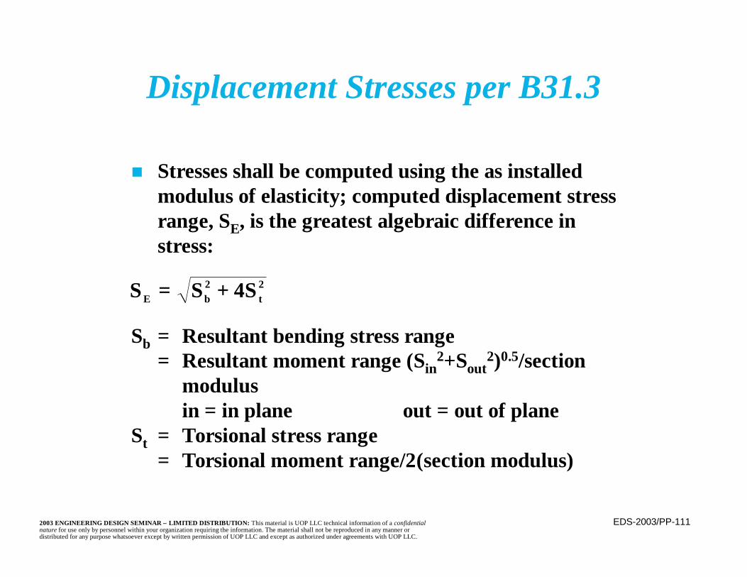
EDS-2003/PP-1112003 ENGINEERING DESIGN SEMINAR – LIMITED DISTRIBUTION: This material is UOP LLC technical information of a confidentialnature for use only by personnel within your organization requiring the information. The material shall not be reproduced in any manner ordistributed for any purpose whatsoever except by written permission of UOP LLC and except as authorized under agreements with UOP LLC.
Displacement Stresses per B31.3
n Stresses shall be computed using the as installedmodulus of elasticity; computed displacement stressrange, SE, is the greatest algebraic difference instress:
Sb = Resultant bending stress range= Resultant moment range (Sin
2+Sout2)0.5/section
modulusin = in plane out = out of plane
St = Torsional stress range= Torsional moment range/2(section modulus)
S S SE b t= +2 24
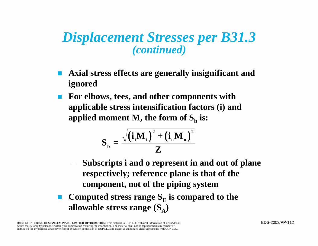
EDS-2003/PP-1122003 ENGINEERING DESIGN SEMINAR – LIMITED DISTRIBUTION: This material is UOP LLC technical information of a confidentialnature for use only by personnel within your organization requiring the information. The material shall not be reproduced in any manner ordistributed for any purpose whatsoever except by written permission of UOP LLC and except as authorized under agreements with UOP LLC.
Displacement Stresses per B31.3(continued)
n Axial stress effects are generally insignificant andignored
n For elbows, tees, and other components withapplicable stress intensification factors (i) andapplied moment M, the form of Sb is:
– Subscripts i and o represent in and out of planerespectively; reference plane is that of thecomponent, not of the piping system
n Computed stress range SE is compared to theallowable stress range (SA)
( ) ( )S
i M i MZb
i i o o= +2 2
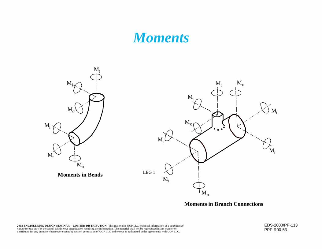
EDS-2003/PP-1132003 ENGINEERING DESIGN SEMINAR – LIMITED DISTRIBUTION: This material is UOP LLC technical information of a confidentialnature for use only by personnel within your organization requiring the information. The material shall not be reproduced in any manner ordistributed for any purpose whatsoever except by written permission of UOP LLC and except as authorized under agreements with UOP LLC.
Moments
PPF-R00-53
Mt
Mi
Mo
Mi
Mt
Mo
Moments in Bends
Mt Mo
Mi
Mt
Mi
Mo
Mi
Mt
Mo
LEG 1
Moments in Branch Connections
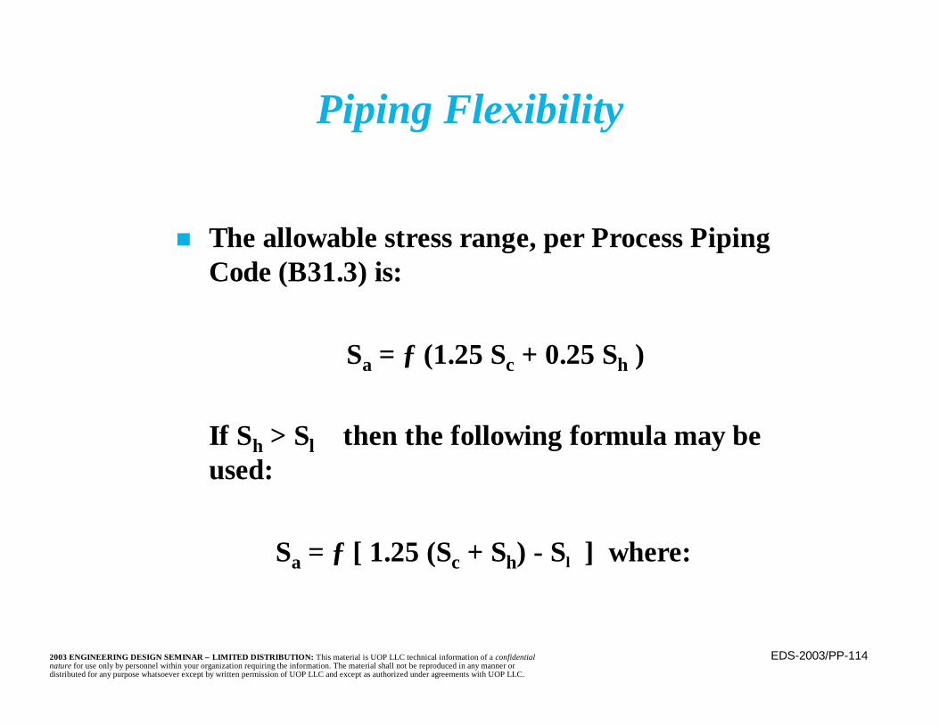
EDS-2003/PP-1142003 ENGINEERING DESIGN SEMINAR – LIMITED DISTRIBUTION: This material is UOP LLC technical information of a confidentialnature for use only by personnel within your organization requiring the information. The material shall not be reproduced in any manner ordistributed for any purpose whatsoever except by written permission of UOP LLC and except as authorized under agreements with UOP LLC.
n The allowable stress range, per Process PipingCode (B31.3) is:
Sa = ƒ (1.25 Sc + 0.25 Sh )
If Sh > Sl then the following formula may beused:
Sa = ƒ [ 1.25 (Sc + Sh) - Sl ] where:
Piping Flexibility
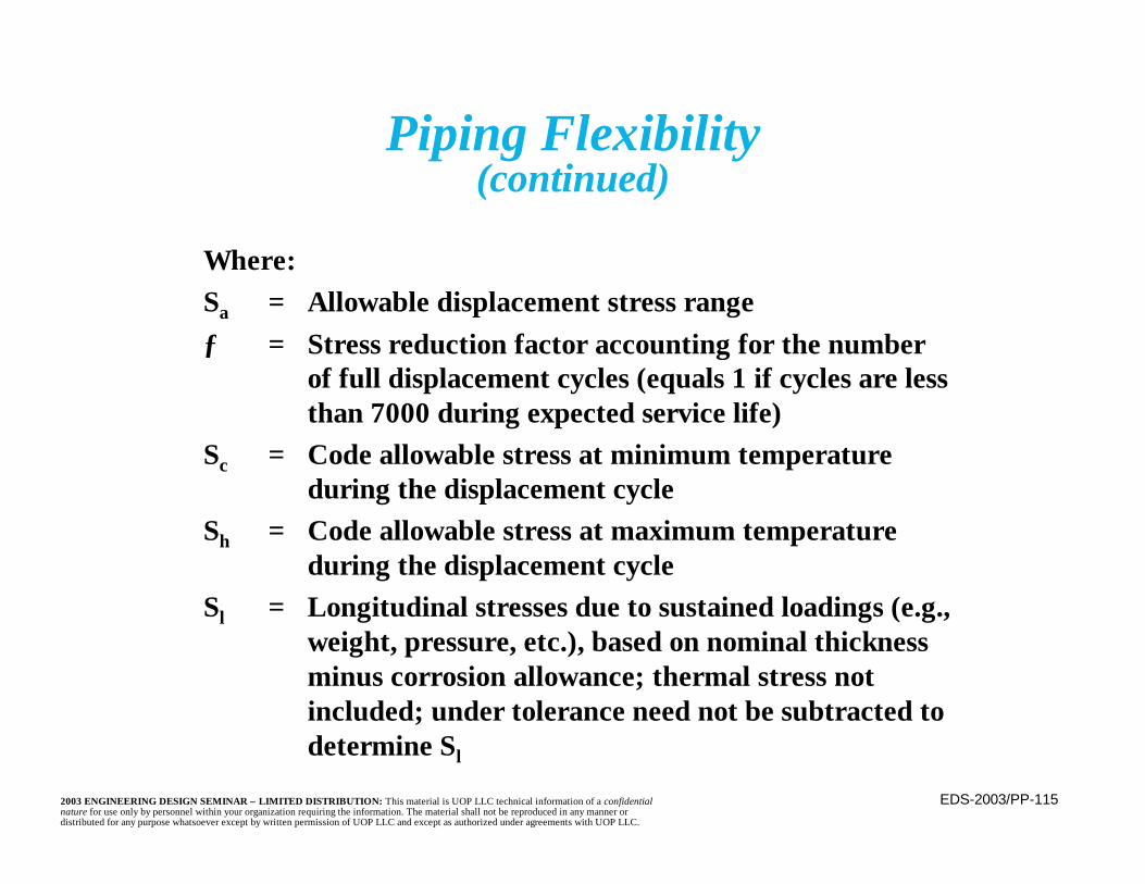
EDS-2003/PP-1152003 ENGINEERING DESIGN SEMINAR – LIMITED DISTRIBUTION: This material is UOP LLC technical information of a confidentialnature for use only by personnel within your organization requiring the information. The material shall not be reproduced in any manner ordistributed for any purpose whatsoever except by written permission of UOP LLC and except as authorized under agreements with UOP LLC.
Piping Flexibility(continued)
Where:Sa = Allowable displacement stress rangeƒ = Stress reduction factor accounting for the number
of full displacement cycles (equals 1 if cycles are lessthan 7000 during expected service life)
Sc = Code allowable stress at minimum temperatureduring the displacement cycle
Sh = Code allowable stress at maximum temperatureduring the displacement cycle
Sl = Longitudinal stresses due to sustained loadings (e.g.,weight, pressure, etc.), based on nominal thicknessminus corrosion allowance; thermal stress notincluded; under tolerance need not be subtracted todetermine Sl
EDS-2003/PP-1162003 ENGINEERING DESIGN SEMINAR – LIMITED DISTRIBUTION: This material is UOP LLC technical information of a confidentialnature for use only by personnel within your organization requiring the information. The material shall not be reproduced in any manner ordistributed for any purpose whatsoever except by written permission of UOP LLC and except as authorized under agreements with UOP LLC.
Piping Flexibility(continued)
n Higher allowable stress is permitted becausestresses are self limiting
n Any local areas exceeding yield, or subject tocreep, deform causing a stress reduction andredistribution
n Although stress range is unchanged, stressvalues will change
EDS-2003/PP-1172003 ENGINEERING DESIGN SEMINAR – LIMITED DISTRIBUTION: This material is UOP LLC technical information of a confidentialnature for use only by personnel within your organization requiring the information. The material shall not be reproduced in any manner ordistributed for any purpose whatsoever except by written permission of UOP LLC and except as authorized under agreements with UOP LLC.
Piping Flexibility(continued)
n Piping stresses are combined vectorially todetermine resultant stresses
– Compare to the allowable stress
n Changing wall thickness of straight pipe doesnot affect thermal bending stress levels
– Both the section modulus and moment ofinertia remain in same ratio
– Reactions at anchors may change
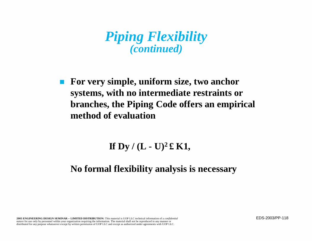
EDS-2003/PP-1182003 ENGINEERING DESIGN SEMINAR – LIMITED DISTRIBUTION: This material is UOP LLC technical information of a confidentialnature for use only by personnel within your organization requiring the information. The material shall not be reproduced in any manner ordistributed for any purpose whatsoever except by written permission of UOP LLC and except as authorized under agreements with UOP LLC.
Piping Flexibility(continued)
n For very simple, uniform size, two anchorsystems, with no intermediate restraints orbranches, the Piping Code offers an empiricalmethod of evaluation
If Dy / (L - U)2 ≤ K1,
No formal flexibility analysis is necessary
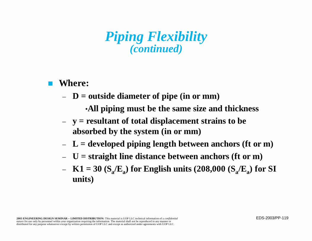
EDS-2003/PP-1192003 ENGINEERING DESIGN SEMINAR – LIMITED DISTRIBUTION: This material is UOP LLC technical information of a confidentialnature for use only by personnel within your organization requiring the information. The material shall not be reproduced in any manner ordistributed for any purpose whatsoever except by written permission of UOP LLC and except as authorized under agreements with UOP LLC.
Piping Flexibility(continued)
n Where:– D = outside diameter of pipe (in or mm)
•All piping must be the same size and thickness– y = resultant of total displacement strains to be
absorbed by the system (in or mm)– L = developed piping length between anchors (ft or m)– U = straight line distance between anchors (ft or m)– K1 = 30 (Sa/Ea) for English units (208,000 (Sa/Ea) for SI
units)

EDS-2003/PP-1202003 ENGINEERING DESIGN SEMINAR – LIMITED DISTRIBUTION: This material is UOP LLC technical information of a confidentialnature for use only by personnel within your organization requiring the information. The material shall not be reproduced in any manner ordistributed for any purpose whatsoever except by written permission of UOP LLC and except as authorized under agreements with UOP LLC.
Example of Simplified Stress Evaluation
PPF-R02-35
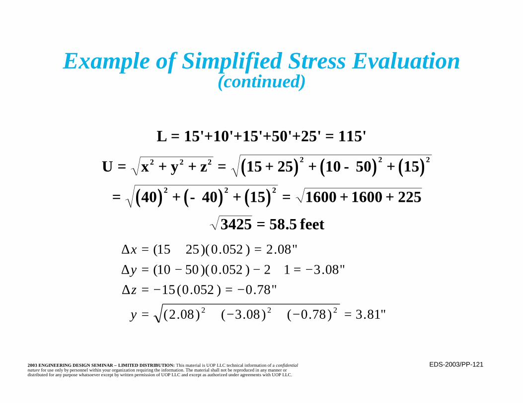
EDS-2003/PP-1212003 ENGINEERING DESIGN SEMINAR – LIMITED DISTRIBUTION: This material is UOP LLC technical information of a confidentialnature for use only by personnel within your organization requiring the information. The material shall not be reproduced in any manner ordistributed for any purpose whatsoever except by written permission of UOP LLC and except as authorized under agreements with UOP LLC.
Example of Simplified Stress Evaluation(continued)
L = 15'+10'+15'+50'+25' = 115'
( ) ( ) ( )( ) ( ) ( )
U x y z= + + = + + − +
= + − + = + +=
2 2 2 2 2 2
2 2 2
15 25 10 50 15
40 40 15 1600 1600 225
3425 58 5. feet
"81.3)78.0()08.3()08.2(
"78.0)052.0(15"08.312)052.0)(5010(
"08.2)052.0)(2515(
222 =−+−+=
−=−=∆−=+−−=∆
=+=∆
y
zyx
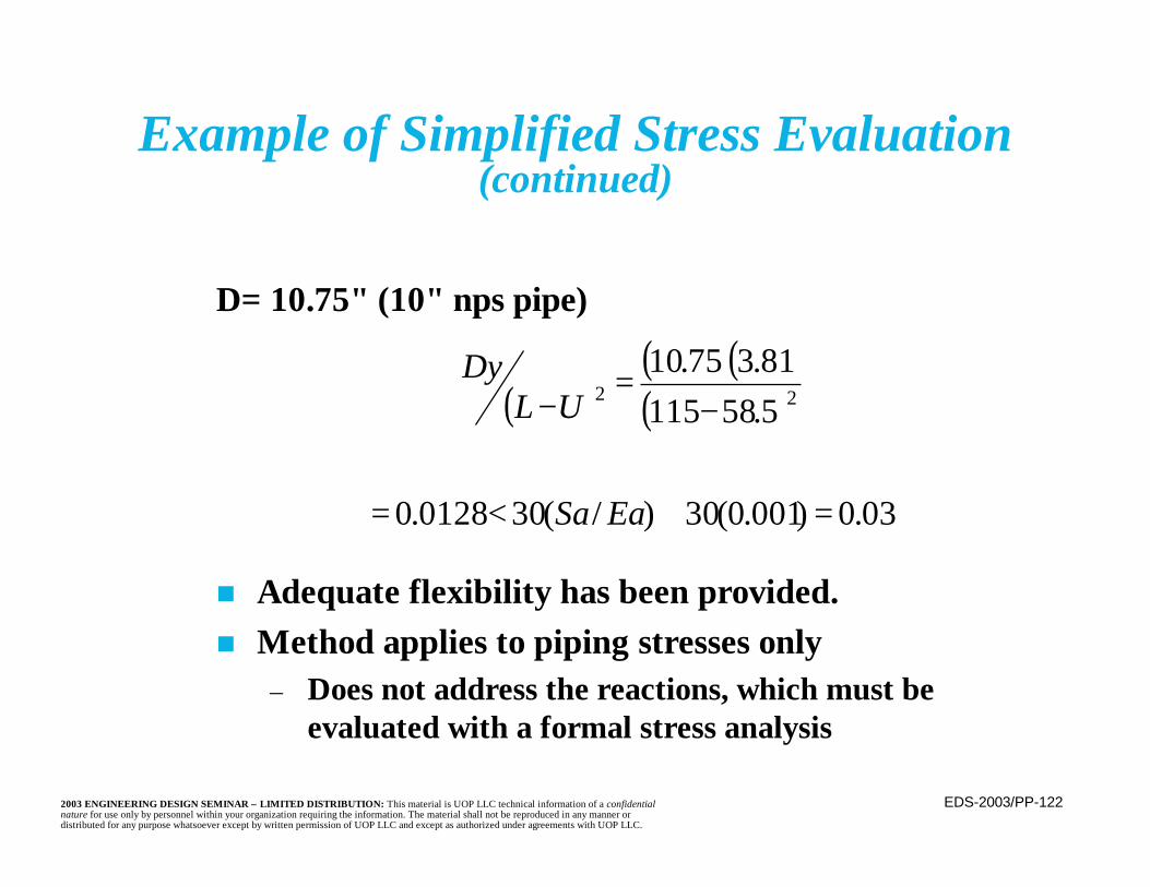
EDS-2003/PP-1222003 ENGINEERING DESIGN SEMINAR – LIMITED DISTRIBUTION: This material is UOP LLC technical information of a confidentialnature for use only by personnel within your organization requiring the information. The material shall not be reproduced in any manner ordistributed for any purpose whatsoever except by written permission of UOP LLC and except as authorized under agreements with UOP LLC.
Example of Simplified Stress Evaluation(continued)
D= 10.75" (10" nps pipe)
n Adequate flexibility has been provided.n Method applies to piping stresses only
– Does not address the reactions, which must beevaluated with a formal stress analysis
( )( )( )( )
03.0)001.0(30)/(300128.0
5.5811581.375.10
22
=≅<=
−=−
EaSa
ULDy
EDS-2003/PP-1232003 ENGINEERING DESIGN SEMINAR – LIMITED DISTRIBUTION: This material is UOP LLC technical information of a confidentialnature for use only by personnel within your organization requiring the information. The material shall not be reproduced in any manner ordistributed for any purpose whatsoever except by written permission of UOP LLC and except as authorized under agreements with UOP LLC.
Piping Flexibility(continued)
n In addition to an evaluation of the stresses,thermal movements must be reviewed to insurethat there is adequate space to accommodatethem, particularly on the pipe rack

EDS-2003/PP-1242003 ENGINEERING DESIGN SEMINAR – LIMITED DISTRIBUTION: This material is UOP LLC technical information of a confidentialnature for use only by personnel within your organization requiring the information. The material shall not be reproduced in any manner ordistributed for any purpose whatsoever except by written permission of UOP LLC and except as authorized under agreements with UOP LLC.
Providing Flexibility
n Flexibility is generally provided by bending ordistortion of the piping
n Installed components, such as valves and flanges,are very stiff and contribute little flexibility
– They may be damaged by imposed bending ordistortion

EDS-2003/PP-1252003 ENGINEERING DESIGN SEMINAR – LIMITED DISTRIBUTION: This material is UOP LLC technical information of a confidentialnature for use only by personnel within your organization requiring the information. The material shall not be reproduced in any manner ordistributed for any purpose whatsoever except by written permission of UOP LLC and except as authorized under agreements with UOP LLC.
n Most common method of increasing flexibility of apiping system is with changes in direction such aspiping loops
– Legs of the loop(s) allow absorption of movementsn Natural arrangement of the piping will often
provide sufficient loops and flexibility– May be necessary to add artificial loops– Horizontal loops on pipe racks are an example
Providing Flexibility(continued)
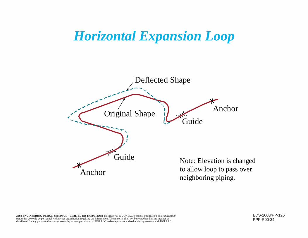
EDS-2003/PP-1262003 ENGINEERING DESIGN SEMINAR – LIMITED DISTRIBUTION: This material is UOP LLC technical information of a confidentialnature for use only by personnel within your organization requiring the information. The material shall not be reproduced in any manner ordistributed for any purpose whatsoever except by written permission of UOP LLC and except as authorized under agreements with UOP LLC.
Horizontal Expansion Loop
PPF-R00-34
Deflected Shape
Original Shape
Guide
GuideAnchor
AnchorNote: Elevation is changedto allow loop to pass overneighboring piping.
EDS-2003/PP-1272003 ENGINEERING DESIGN SEMINAR – LIMITED DISTRIBUTION: This material is UOP LLC technical information of a confidentialnature for use only by personnel within your organization requiring the information. The material shall not be reproduced in any manner ordistributed for any purpose whatsoever except by written permission of UOP LLC and except as authorized under agreements with UOP LLC.
Providing Flexibility(continued)
n Loops do, however, add to piping length andpressure drop
n Vertical direction changes may also createhigh or low points (local as well as global)that require vents or drains

EDS-2003/PP-1282003 ENGINEERING DESIGN SEMINAR – LIMITED DISTRIBUTION: This material is UOP LLC technical information of a confidentialnature for use only by personnel within your organization requiring the information. The material shall not be reproduced in any manner ordistributed for any purpose whatsoever except by written permission of UOP LLC and except as authorized under agreements with UOP LLC.
Loop Example
PPF-R00-84

EDS-2003/PP-1292003 ENGINEERING DESIGN SEMINAR – LIMITED DISTRIBUTION: This material is UOP LLC technical information of a confidentialnature for use only by personnel within your organization requiring the information. The material shall not be reproduced in any manner ordistributed for any purpose whatsoever except by written permission of UOP LLC and except as authorized under agreements with UOP LLC.
Loop Examples
PPF-R00-85

EDS-2003/PP-1302003 ENGINEERING DESIGN SEMINAR – LIMITED DISTRIBUTION: This material is UOP LLC technical information of a confidentialnature for use only by personnel within your organization requiring the information. The material shall not be reproduced in any manner ordistributed for any purpose whatsoever except by written permission of UOP LLC and except as authorized under agreements with UOP LLC.
Providing Flexibility(continued)
n Elbows increase the flexibility, but are alsopoints of stress concentration
n Piping Code contains– Flexibility factors
• Accounts for reduced stiffness– Stress intensification factors
• Accounts for higher stresses at these points

EDS-2003/PP-1312003 ENGINEERING DESIGN SEMINAR – LIMITED DISTRIBUTION: This material is UOP LLC technical information of a confidentialnature for use only by personnel within your organization requiring the information. The material shall not be reproduced in any manner ordistributed for any purpose whatsoever except by written permission of UOP LLC and except as authorized under agreements with UOP LLC.
Providing Flexibility(continued)
n In low pressure (usually below 50 - 60 psig),critical, cases, where loops are not an option,expansion joints may be considered
n Expansion joints consist of one or moreflexible bellows that may compress, elongate,or rotate slightly to absorb piping movements
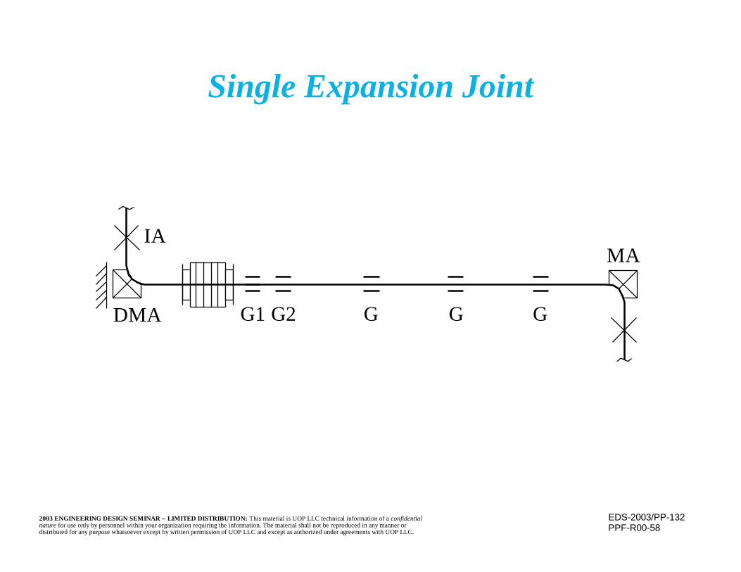
EDS-2003/PP-1322003 ENGINEERING DESIGN SEMINAR – LIMITED DISTRIBUTION: This material is UOP LLC technical information of a confidentialnature for use only by personnel within your organization requiring the information. The material shall not be reproduced in any manner ordistributed for any purpose whatsoever except by written permission of UOP LLC and except as authorized under agreements with UOP LLC.
Single Expansion Joint
PPF-R00-58
IA
DMA
MA
G1 G2 G G G
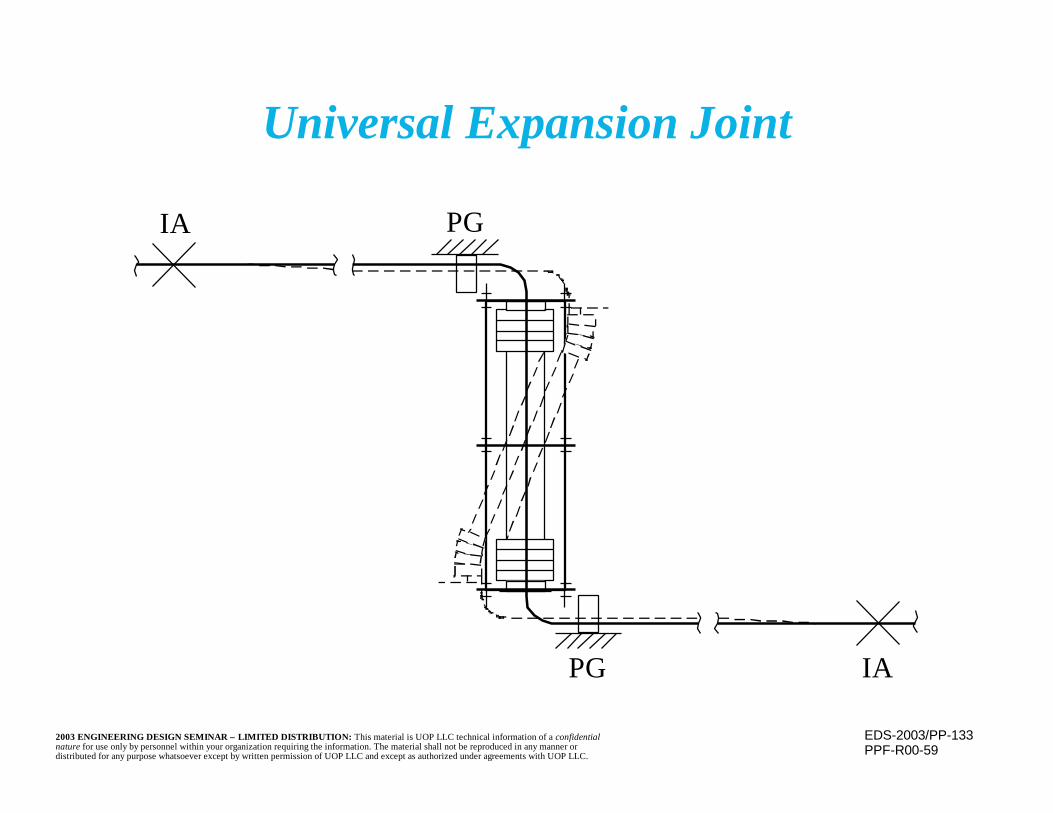
EDS-2003/PP-1332003 ENGINEERING DESIGN SEMINAR – LIMITED DISTRIBUTION: This material is UOP LLC technical information of a confidentialnature for use only by personnel within your organization requiring the information. The material shall not be reproduced in any manner ordistributed for any purpose whatsoever except by written permission of UOP LLC and except as authorized under agreements with UOP LLC.
Universal Expansion Joint
PPF-R00-59
IA
PG
PG
IA
EDS-2003/PP-1342003 ENGINEERING DESIGN SEMINAR – LIMITED DISTRIBUTION: This material is UOP LLC technical information of a confidentialnature for use only by personnel within your organization requiring the information. The material shall not be reproduced in any manner ordistributed for any purpose whatsoever except by written permission of UOP LLC and except as authorized under agreements with UOP LLC.
Providing Flexibility(continued)
n Expansion joints cannot transmit forces acrossthe bellows
– Piping forces, including “blowout” on thebellows, must be absorbed by piping system, viaanchors
– Some special joints (tied, hinged, or pressurebalanced) do permit transmission of axial forces

EDS-2003/PP-1352003 ENGINEERING DESIGN SEMINAR – LIMITED DISTRIBUTION: This material is UOP LLC technical information of a confidentialnature for use only by personnel within your organization requiring the information. The material shall not be reproduced in any manner ordistributed for any purpose whatsoever except by written permission of UOP LLC and except as authorized under agreements with UOP LLC.
Expansion Joint Blowout Force
PPF-R00-65
Reaction Force on Nozzles = (P)AAnnulus AAnnulus =Force at Vessel Support = (P)ABellows
Blowout Force FB = ABellows =eff2D
4P π
( )2eff
2 dD4
−π
eff2D
4π
EDS-2003/PP-1362003 ENGINEERING DESIGN SEMINAR – LIMITED DISTRIBUTION: This material is UOP LLC technical information of a confidentialnature for use only by personnel within your organization requiring the information. The material shall not be reproduced in any manner ordistributed for any purpose whatsoever except by written permission of UOP LLC and except as authorized under agreements with UOP LLC.
Providing Flexibility(continued)
n Expansion joints are tested in place to confirmthe adequacy of the main anchors.
– Test pressure is no more than 150% of designpressure
n Joints are normally installed in vertical positionto allow draining of corrugations
– Otherwise, a means of drainage is necessary

EDS-2003/PP-1372003 ENGINEERING DESIGN SEMINAR – LIMITED DISTRIBUTION: This material is UOP LLC technical information of a confidentialnature for use only by personnel within your organization requiring the information. The material shall not be reproduced in any manner ordistributed for any purpose whatsoever except by written permission of UOP LLC and except as authorized under agreements with UOP LLC.
Providing Flexibility(continued)
n Many types and configurations of expansionjoints are available
– Allows absorption of sometimes largemovements
n Expansion joint designs are governed by theExpansion Joint Manufacturers Association(EJMA) Standards and Appendix X of B31.3
EDS-2003/PP-1382003 ENGINEERING DESIGN SEMINAR – LIMITED DISTRIBUTION: This material is UOP LLC technical information of a confidentialnature for use only by personnel within your organization requiring the information. The material shall not be reproduced in any manner ordistributed for any purpose whatsoever except by written permission of UOP LLC and except as authorized under agreements with UOP LLC.
Expansion Joint Bellows
n Bellows must be flexible to allow deformationand movement absorption
– Are very thin
n Bellows stiffness (spring constant -- axial,rotation, or torsional) must be overcome beforethe bellows will deform
EDS-2003/PP-1392003 ENGINEERING DESIGN SEMINAR – LIMITED DISTRIBUTION: This material is UOP LLC technical information of a confidentialnature for use only by personnel within your organization requiring the information. The material shall not be reproduced in any manner ordistributed for any purpose whatsoever except by written permission of UOP LLC and except as authorized under agreements with UOP LLC.
Expansion Joint Bellows(continued)
n Bellows must be strong to withstand internalpressure and local stress at the bends (whichmust retain a smooth radius)
n To provide needed strength and corrosionresistance, at generally elevated temperatures(causing significant movements to be absorbed)and still be thin and therefore flexible, bellowsare constructed of high alloy material
EDS-2003/PP-1402003 ENGINEERING DESIGN SEMINAR – LIMITED DISTRIBUTION: This material is UOP LLC technical information of a confidentialnature for use only by personnel within your organization requiring the information. The material shall not be reproduced in any manner ordistributed for any purpose whatsoever except by written permission of UOP LLC and except as authorized under agreements with UOP LLC.
Expansion Joint Bellows(continued)
n Multi-ply bellows (made of several independentlayers) allow greater thickness, strength, andflexibility
– Layers can move relative to each other– Inspection and maintenance is a problem– Leak detection between layers is required to
detect inner layer failure– Weld joint details are more complex where the
bellows joins the pipe– If one ply fails, the rest are not adequate to
withstand the pressure

EDS-2003/PP-1412003 ENGINEERING DESIGN SEMINAR – LIMITED DISTRIBUTION: This material is UOP LLC technical information of a confidentialnature for use only by personnel within your organization requiring the information. The material shall not be reproduced in any manner ordistributed for any purpose whatsoever except by written permission of UOP LLC and except as authorized under agreements with UOP LLC.
Expansion Joint Bellows(continued)
n Maintenance of thin bellows, and protection fromdamage, is critical
– Small amounts of corrosion or damage may be“fatal”
n Bellows are generally purged to avoid contaminantaccumulation
– Purge must not result in liquid water formation oraccumulation which can result in very corrosivematerials (e.g. polytheonic acid)
n Reduce the net offset movement the bellows oruniversal joint must take by using an initial offset
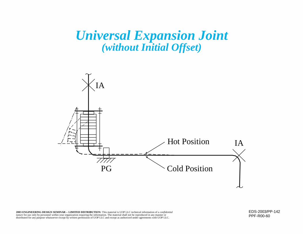
EDS-2003/PP-1422003 ENGINEERING DESIGN SEMINAR – LIMITED DISTRIBUTION: This material is UOP LLC technical information of a confidentialnature for use only by personnel within your organization requiring the information. The material shall not be reproduced in any manner ordistributed for any purpose whatsoever except by written permission of UOP LLC and except as authorized under agreements with UOP LLC.
Universal Expansion Joint(without Initial Offset)
PPF-R00-60
PG
IA
IAHot Position
Cold Position
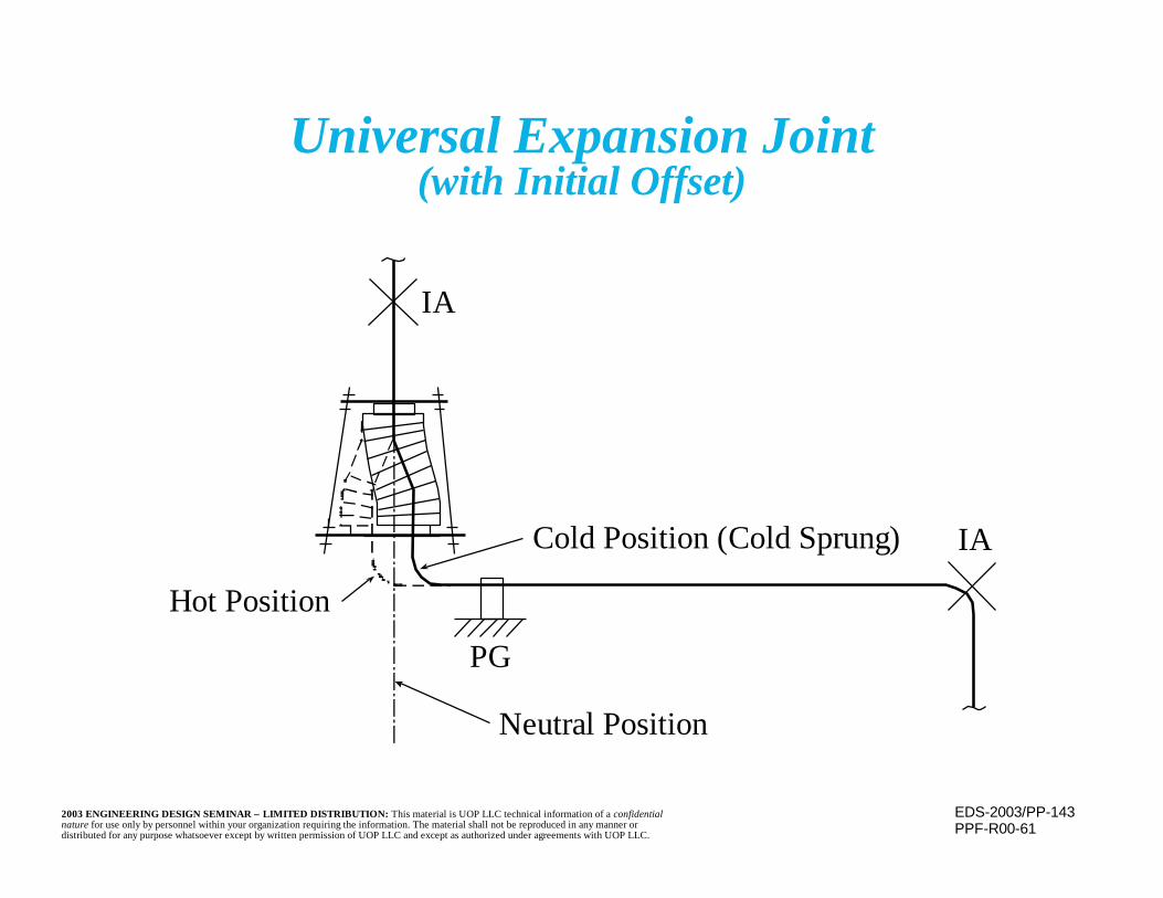
EDS-2003/PP-1432003 ENGINEERING DESIGN SEMINAR – LIMITED DISTRIBUTION: This material is UOP LLC technical information of a confidentialnature for use only by personnel within your organization requiring the information. The material shall not be reproduced in any manner ordistributed for any purpose whatsoever except by written permission of UOP LLC and except as authorized under agreements with UOP LLC.
Universal Expansion Joint(with Initial Offset)
PPF-R00-61
PG
IA
IACold Position (Cold Sprung)
Hot Position
Neutral Position
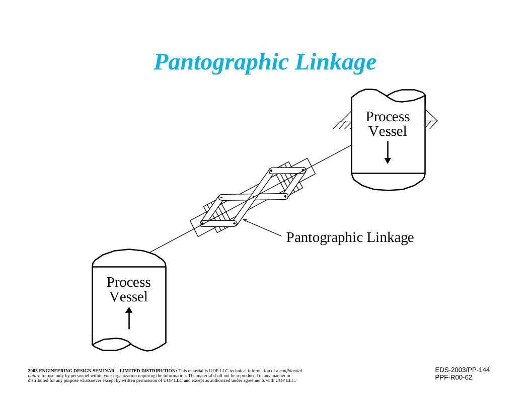
EDS-2003/PP-1442003 ENGINEERING DESIGN SEMINAR – LIMITED DISTRIBUTION: This material is UOP LLC technical information of a confidentialnature for use only by personnel within your organization requiring the information. The material shall not be reproduced in any manner ordistributed for any purpose whatsoever except by written permission of UOP LLC and except as authorized under agreements with UOP LLC.
Pantographic Linkage
PPF-R00-62
Pantographic Linkage
ProcessVessel
ProcessVessel
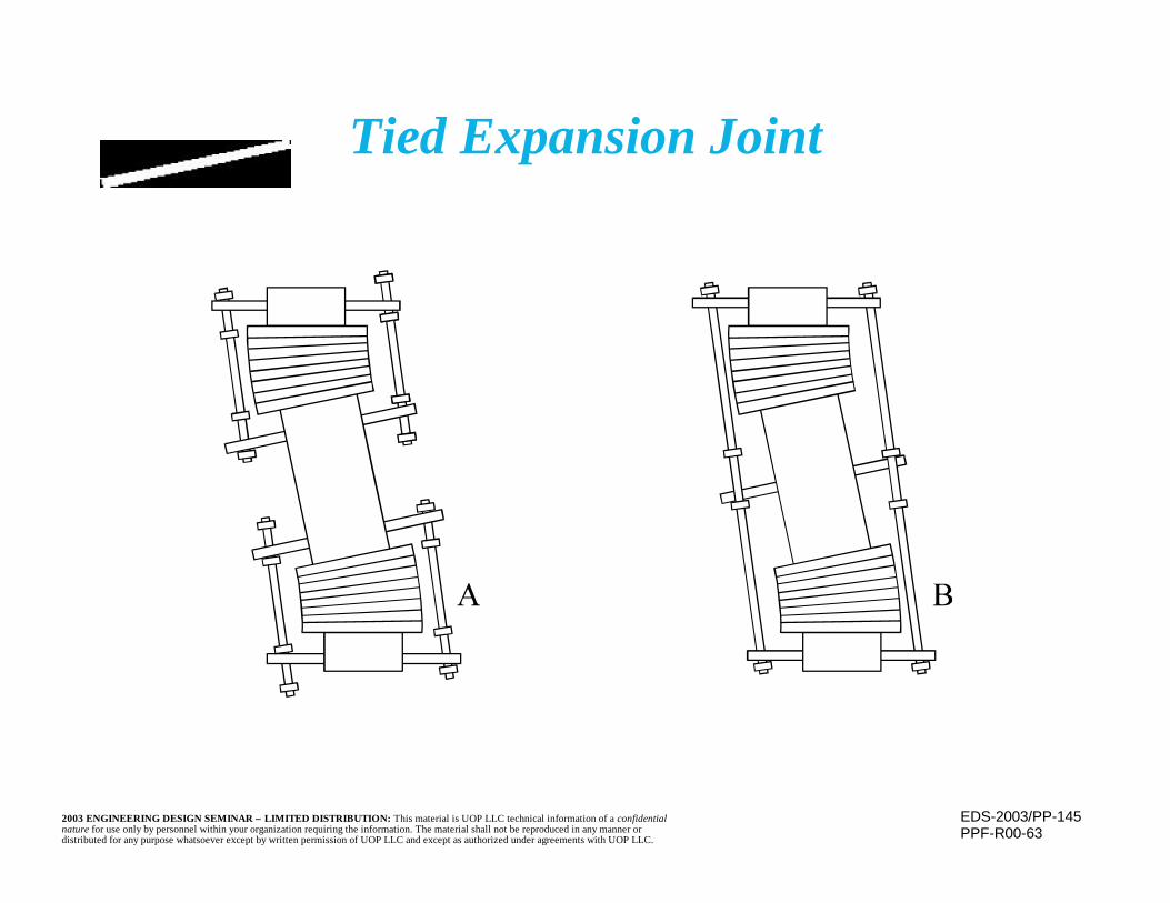
EDS-2003/PP-1452003 ENGINEERING DESIGN SEMINAR – LIMITED DISTRIBUTION: This material is UOP LLC technical information of a confidentialnature for use only by personnel within your organization requiring the information. The material shall not be reproduced in any manner ordistributed for any purpose whatsoever except by written permission of UOP LLC and except as authorized under agreements with UOP LLC.
Tied Expansion Joint
PPF-R00-63

EDS-2003/PP-1462003 ENGINEERING DESIGN SEMINAR – LIMITED DISTRIBUTION: This material is UOP LLC technical information of a confidentialnature for use only by personnel within your organization requiring the information. The material shall not be reproduced in any manner ordistributed for any purpose whatsoever except by written permission of UOP LLC and except as authorized under agreements with UOP LLC.
Pressure Balanced Expansion Joint
PPF-R00-57
Machine
IA
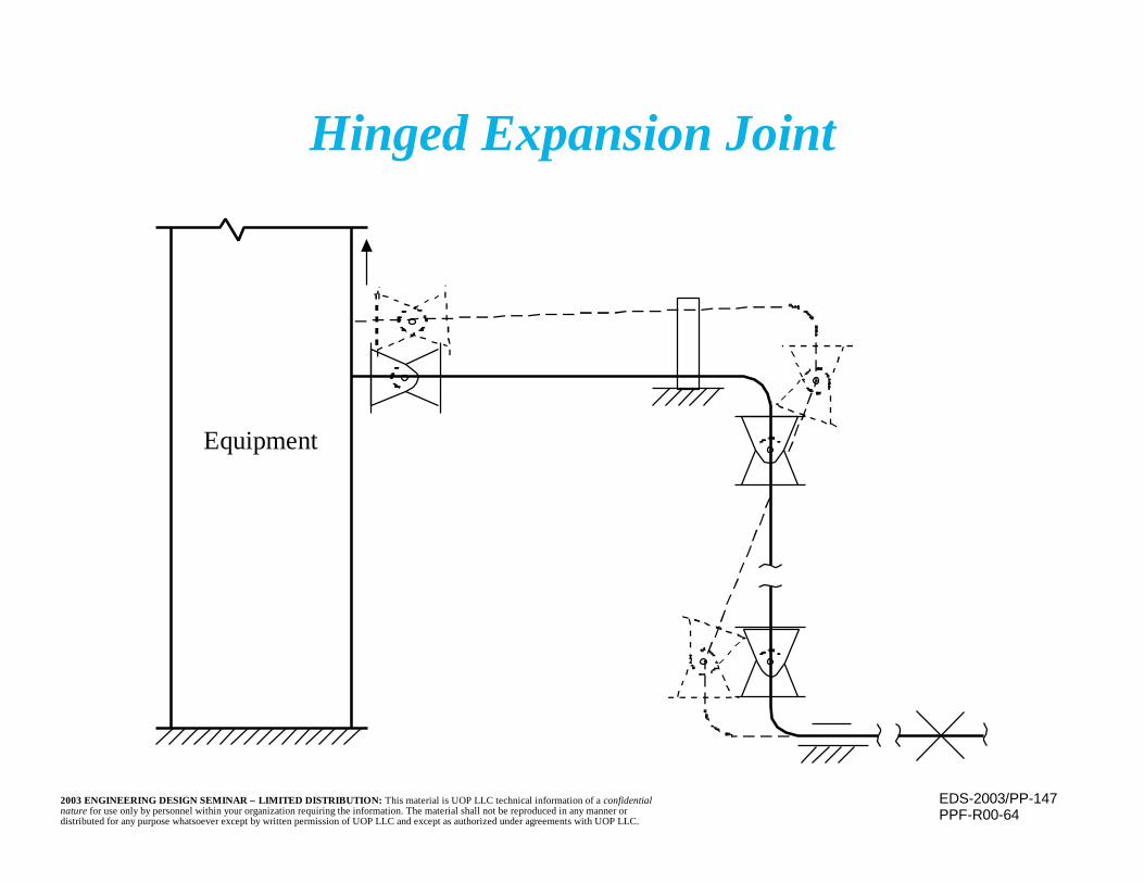
EDS-2003/PP-1472003 ENGINEERING DESIGN SEMINAR – LIMITED DISTRIBUTION: This material is UOP LLC technical information of a confidentialnature for use only by personnel within your organization requiring the information. The material shall not be reproduced in any manner ordistributed for any purpose whatsoever except by written permission of UOP LLC and except as authorized under agreements with UOP LLC.
Hinged Expansion Joint
PPF-R00-64
Equipment
EDS-2003/PP-1482003 ENGINEERING DESIGN SEMINAR – LIMITED DISTRIBUTION: This material is UOP LLC technical information of a confidentialnature for use only by personnel within your organization requiring the information. The material shall not be reproduced in any manner ordistributed for any purpose whatsoever except by written permission of UOP LLC and except as authorized under agreements with UOP LLC.
Elastic Followup
n Elastic followup is a phenomenon that may occurin “unbalanced” piping systems
– Results in overstress or a creep or fatigue failureafter a (possibly lengthy) period of satisfactoryservice
– Normal stress/flexibility analysis will not indicatea problem
• Makes detection or prediction more difficult– Stresses cannot be considered to be proportional
to strains throughout the system
EDS-2003/PP-1492003 ENGINEERING DESIGN SEMINAR – LIMITED DISTRIBUTION: This material is UOP LLC technical information of a confidentialnature for use only by personnel within your organization requiring the information. The material shall not be reproduced in any manner ordistributed for any purpose whatsoever except by written permission of UOP LLC and except as authorized under agreements with UOP LLC.
Elastic Follow-up(continued)
n For elastic follow-up to occur, two conditionsmust be present
– System, or a portion of it, must operate within thecreep range of piping materials.
– System must be unbalanced, i.e., some areas mustbe hotter, more highly stressed, or less stiff thanothers. These are the relatively weak areas.
EDS-2003/PP-1502003 ENGINEERING DESIGN SEMINAR – LIMITED DISTRIBUTION: This material is UOP LLC technical information of a confidentialnature for use only by personnel within your organization requiring the information. The material shall not be reproduced in any manner ordistributed for any purpose whatsoever except by written permission of UOP LLC and except as authorized under agreements with UOP LLC.
Elastic Followup(continued)
n Over time, the more highly stressed, weaker, orhotter portions tend to creep more than remainderof system
n Strain in the system is concentrated in theselocations (which may be local)
– If weak areas perform elastically, increase in strainmeans increase in stress
• Areas are more highly stressed (remainder ofsystem less stressed) than predicted
– If weak areas perform inelastically, they may developcreep (or fatigue) damage, even if increased strainresults in little or no stress increase
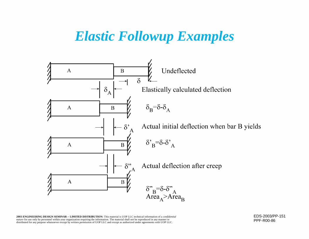
EDS-2003/PP-1512003 ENGINEERING DESIGN SEMINAR – LIMITED DISTRIBUTION: This material is UOP LLC technical information of a confidentialnature for use only by personnel within your organization requiring the information. The material shall not be reproduced in any manner ordistributed for any purpose whatsoever except by written permission of UOP LLC and except as authorized under agreements with UOP LLC.
Elastic Followup Examples
PPF-R00-86
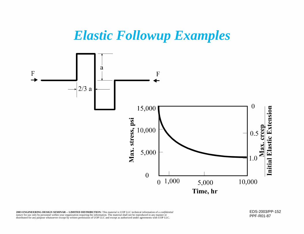
EDS-2003/PP-1522003 ENGINEERING DESIGN SEMINAR – LIMITED DISTRIBUTION: This material is UOP LLC technical information of a confidentialnature for use only by personnel within your organization requiring the information. The material shall not be reproduced in any manner ordistributed for any purpose whatsoever except by written permission of UOP LLC and except as authorized under agreements with UOP LLC.
Elastic Followup Examples
PPF-R01-87

EDS-2003/PP-1532003 ENGINEERING DESIGN SEMINAR – LIMITED DISTRIBUTION: This material is UOP LLC technical information of a confidentialnature for use only by personnel within your organization requiring the information. The material shall not be reproduced in any manner ordistributed for any purpose whatsoever except by written permission of UOP LLC and except as authorized under agreements with UOP LLC.
Elastic Followup Examples
PPF-R00-88
EDS-2003/PP-1542003 ENGINEERING DESIGN SEMINAR – LIMITED DISTRIBUTION: This material is UOP LLC technical information of a confidentialnature for use only by personnel within your organization requiring the information. The material shall not be reproduced in any manner ordistributed for any purpose whatsoever except by written permission of UOP LLC and except as authorized under agreements with UOP LLC.
Elastic Followup(continued)
n Normal flexibility/stress analysis is indicativeof initial, pre-creep condition and is basedupon stress, not strain, status
– Strain redistributions due to creep are notaccounted for
– Damage, or failure, may occur
EDS-2003/PP-1552003 ENGINEERING DESIGN SEMINAR – LIMITED DISTRIBUTION: This material is UOP LLC technical information of a confidentialnature for use only by personnel within your organization requiring the information. The material shall not be reproduced in any manner ordistributed for any purpose whatsoever except by written permission of UOP LLC and except as authorized under agreements with UOP LLC.
Elastic Followup(continued)
n May be prevented by:– Avoiding use of unbalanced systems– Lowering long term operating temperatures
below the creep range– Use of materials with higher creep range
threshold temperatures

EDS-2003/PP-1562003 ENGINEERING DESIGN SEMINAR – LIMITED DISTRIBUTION: This material is UOP LLC technical information of a confidentialnature for use only by personnel within your organization requiring the information. The material shall not be reproduced in any manner ordistributed for any purpose whatsoever except by written permission of UOP LLC and except as authorized under agreements with UOP LLC.
Elastic Follow-up(continued)
n May be prevented by (continued)– Design for overall low piping strains that
remain low even with redistribution– Creative support/restraint systems to prevent
strain redistribution, including the selectiveuse of cold spring
• Care must be taken not to imposeadditional stresses into the piping system
EDS-2003/PP-1572003 ENGINEERING DESIGN SEMINAR – LIMITED DISTRIBUTION: This material is UOP LLC technical information of a confidentialnature for use only by personnel within your organization requiring the information. The material shall not be reproduced in any manner ordistributed for any purpose whatsoever except by written permission of UOP LLC and except as authorized under agreements with UOP LLC.
Piping Support
n Pipe supports must carry the weight of thepiping, with contents, and account for thermalmovements and loads
n As a general rule, minimizing restrictions tothe piping’s thermal movement will minimizepipe stresses and reactions
– Means fewer guides, anchors and otherrestrictions is better
– In some cases, problems can be resolved byremoving restraints
EDS-2003/PP-1582003 ENGINEERING DESIGN SEMINAR – LIMITED DISTRIBUTION: This material is UOP LLC technical information of a confidentialnature for use only by personnel within your organization requiring the information. The material shall not be reproduced in any manner ordistributed for any purpose whatsoever except by written permission of UOP LLC and except as authorized under agreements with UOP LLC.
Piping Support(continued)
n Avoid placing portions of the piping system incompression
– Buckling may occur– For example, support vertical runs of pipe
from the top rather than the bottom
n Piping identified as “Free Draining” mustgravity flow in the indicated direction duringall operating, start-up, shut-down, out-ofservice, and other conditions.
EDS-2003/PP-1592003 ENGINEERING DESIGN SEMINAR – LIMITED DISTRIBUTION: This material is UOP LLC technical information of a confidentialnature for use only by personnel within your organization requiring the information. The material shall not be reproduced in any manner ordistributed for any purpose whatsoever except by written permission of UOP LLC and except as authorized under agreements with UOP LLC.
Piping Support(continued)
n Often, load limitations on attached equipment(eg, pumps), locally high stress, or limits on themagnitude of the movement that can bepermitted require that thermal movements berestricted via guides, anchors, etc
n Restricting thermal movements will result inimposition of a force on the resisting supportand cause stresses within piping
EDS-2003/PP-1602003 ENGINEERING DESIGN SEMINAR – LIMITED DISTRIBUTION: This material is UOP LLC technical information of a confidentialnature for use only by personnel within your organization requiring the information. The material shall not be reproduced in any manner ordistributed for any purpose whatsoever except by written permission of UOP LLC and except as authorized under agreements with UOP LLC.
n There are many ways to provide supportn Pipe “shoes” beneath the piping
– Shoes allow axial and, if permitted, out ofplane movement; may even lift off the supportduring operation
– Guides, possibly with a clamp over the shoe,may be used to limit or restrict movements
– Care must be taken to insure shoe cannot slideoff support and “bind” at any time
Piping Support(continued)
EDS-2003/PP-1612003 ENGINEERING DESIGN SEMINAR – LIMITED DISTRIBUTION: This material is UOP LLC technical information of a confidentialnature for use only by personnel within your organization requiring the information. The material shall not be reproduced in any manner ordistributed for any purpose whatsoever except by written permission of UOP LLC and except as authorized under agreements with UOP LLC.
Piping Support(continued)
n Provide low friction slide plates (Teflon orgraphite) to minimize the effects of frictionwhere movement is required
n Limit stops allow the pipe to move a certainamount, then halt further movement

EDS-2003/PP-1622003 ENGINEERING DESIGN SEMINAR – LIMITED DISTRIBUTION: This material is UOP LLC technical information of a confidentialnature for use only by personnel within your organization requiring the information. The material shall not be reproduced in any manner ordistributed for any purpose whatsoever except by written permission of UOP LLC and except as authorized under agreements with UOP LLC.
Pipe Shoe Details
PPF-R00-46
L Support UnlessPipe Otherwise Noted
Shoe
Support Beam Bar (N.S. & F.S.)
Shoe
L Support UnlessPipe Otherwise Noted
Support Beam
ShoeSupportBeam
ShoeBar (N.S. & F.S.)
Support Beam
EDS-2003/PP-1632003 ENGINEERING DESIGN SEMINAR – LIMITED DISTRIBUTION: This material is UOP LLC technical information of a confidentialnature for use only by personnel within your organization requiring the information. The material shall not be reproduced in any manner ordistributed for any purpose whatsoever except by written permission of UOP LLC and except as authorized under agreements with UOP LLC.
Piping Support(continued)
n Hangers provide a rigid vertical support,while allowing horizontal movement
n Anchors are any system that does not allowany piping movement at that point
n Piping supports must be provided to preventexcessive piping deformation from piping’sweight (sag)
– Supports must also allow retention of any freedraining requirements, without creatingpockets in piping system

EDS-2003/PP-1642003 ENGINEERING DESIGN SEMINAR – LIMITED DISTRIBUTION: This material is UOP LLC technical information of a confidentialnature for use only by personnel within your organization requiring the information. The material shall not be reproduced in any manner ordistributed for any purpose whatsoever except by written permission of UOP LLC and except as authorized under agreements with UOP LLC.
Pipe Support Assembly
PPF-R00-47
L 3/4" BoltsL Pipe
Vessel LugSupport Bracket
Support Strap
Support LugN.S. & F.S.
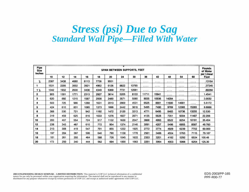
EDS-2003/PP-1652003 ENGINEERING DESIGN SEMINAR – LIMITED DISTRIBUTION: This material is UOP LLC technical information of a confidentialnature for use only by personnel within your organization requiring the information. The material shall not be reproduced in any manner ordistributed for any purpose whatsoever except by written permission of UOP LLC and except as authorized under agreements with UOP LLC.
Stress (psi) Due to SagStandard Wall Pipe— Filled With Water
PPF-R00-77
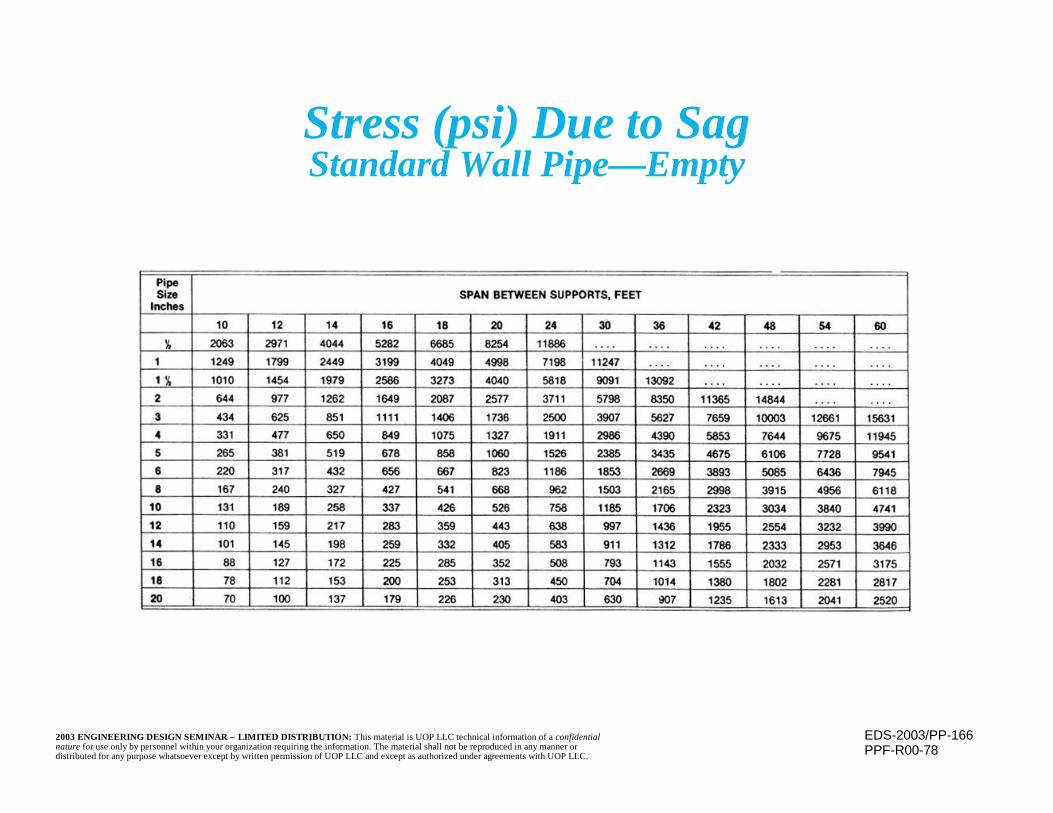
EDS-2003/PP-1662003 ENGINEERING DESIGN SEMINAR – LIMITED DISTRIBUTION: This material is UOP LLC technical information of a confidentialnature for use only by personnel within your organization requiring the information. The material shall not be reproduced in any manner ordistributed for any purpose whatsoever except by written permission of UOP LLC and except as authorized under agreements with UOP LLC.
Stress (psi) Due to SagStandard Wall Pipe— Empty
PPF-R00-78

EDS-2003/PP-1672003 ENGINEERING DESIGN SEMINAR – LIMITED DISTRIBUTION: This material is UOP LLC technical information of a confidentialnature for use only by personnel within your organization requiring the information. The material shall not be reproduced in any manner ordistributed for any purpose whatsoever except by written permission of UOP LLC and except as authorized under agreements with UOP LLC.
Maximum Pipe Spans (Feet)
PPF-R00-79
Basis: simple span; carbon steel pipe; water or lighter fluid service;maximum temperature 650°F
Criteria: maximum stress = 6000psi*Maximum deflection = smaller of 1" or nominal pipe diameter
EDS-2003/PP-1682003 ENGINEERING DESIGN SEMINAR – LIMITED DISTRIBUTION: This material is UOP LLC technical information of a confidentialnature for use only by personnel within your organization requiring the information. The material shall not be reproduced in any manner ordistributed for any purpose whatsoever except by written permission of UOP LLC and except as authorized under agreements with UOP LLC.
Piping Vibration
n Many potential causes of vibration– Connected equipment
• Pumps• Compressors
– Flow characteristics• Flashing• Intermittent flow• Two-phase flow• Water hammer• Etc.
EDS-2003/PP-1692003 ENGINEERING DESIGN SEMINAR – LIMITED DISTRIBUTION: This material is UOP LLC technical information of a confidentialnature for use only by personnel within your organization requiring the information. The material shall not be reproduced in any manner ordistributed for any purpose whatsoever except by written permission of UOP LLC and except as authorized under agreements with UOP LLC.
Vibration Control
n Design piping system and its supports to have acritical frequency well away from the excitingfrequency
n Isolate vibrating equipment from the pipingsystem
n Maintain uniform process temperature andminimize piping length and elbows to controlvibration caused by flow characteristics

EDS-2003/PP-1702003 ENGINEERING DESIGN SEMINAR – LIMITED DISTRIBUTION: This material is UOP LLC technical information of a confidentialnature for use only by personnel within your organization requiring the information. The material shall not be reproduced in any manner ordistributed for any purpose whatsoever except by written permission of UOP LLC and except as authorized under agreements with UOP LLC.
Vibration Control(continued)
n Use snubbers or dampers to slow the systemsresponse to excitation, while retainingflexibility
n Use guides to limit amplitude of vibration
n “Dead leg” tees rather than elbows may helpreduce vibration
EDS-2003/PP-1712003 ENGINEERING DESIGN SEMINAR – LIMITED DISTRIBUTION: This material is UOP LLC technical information of a confidentialnature for use only by personnel within your organization requiring the information. The material shall not be reproduced in any manner ordistributed for any purpose whatsoever except by written permission of UOP LLC and except as authorized under agreements with UOP LLC.
“Floating” Systems
n A “floating” system has either no intermediatesupports or supports capable of absorbing onlya fixed load (e.g., a constant spring support)
n Unless all weights and loading conditions areknown, “floating” systems are avoided becauseany unanticipated or misestimated load can beabsorbed only at the ends
n Load transmission through the system to theends creates additional strains and stresses
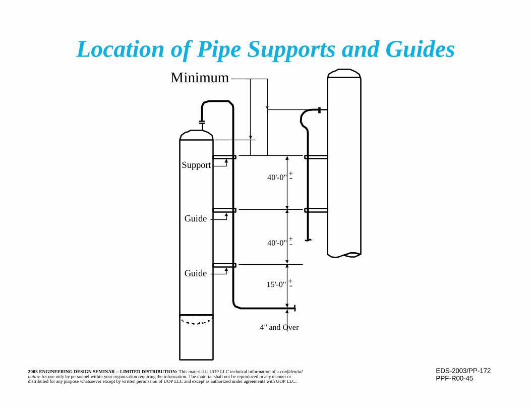
EDS-2003/PP-1722003 ENGINEERING DESIGN SEMINAR – LIMITED DISTRIBUTION: This material is UOP LLC technical information of a confidentialnature for use only by personnel within your organization requiring the information. The material shall not be reproduced in any manner ordistributed for any purpose whatsoever except by written permission of UOP LLC and except as authorized under agreements with UOP LLC.
Location of Pipe Supports and Guides
PPF-R00-45
Minimum
40'-0" +-
40'-0" +-
15'-0" +-
4" and Over
Support
Guide
Guide
EDS-2003/PP-1732003 ENGINEERING DESIGN SEMINAR – LIMITED DISTRIBUTION: This material is UOP LLC technical information of a confidentialnature for use only by personnel within your organization requiring the information. The material shall not be reproduced in any manner ordistributed for any purpose whatsoever except by written permission of UOP LLC and except as authorized under agreements with UOP LLC.
Spring Hangers
n Spring hangers are systems designed to providesupport while allowing vertical movement
n Two kinds are available– Variable
• Less expensive– Constant
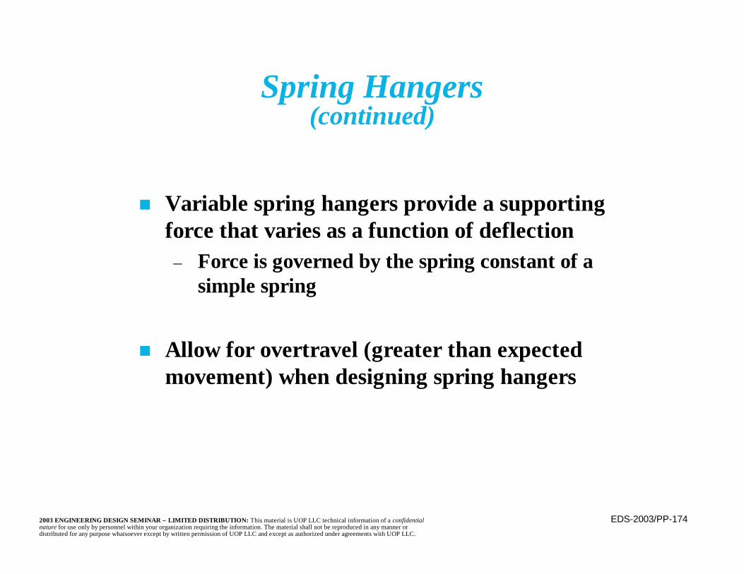
EDS-2003/PP-1742003 ENGINEERING DESIGN SEMINAR – LIMITED DISTRIBUTION: This material is UOP LLC technical information of a confidentialnature for use only by personnel within your organization requiring the information. The material shall not be reproduced in any manner ordistributed for any purpose whatsoever except by written permission of UOP LLC and except as authorized under agreements with UOP LLC.
Spring Hangers(continued)
n Variable spring hangers provide a supportingforce that varies as a function of deflection
– Force is governed by the spring constant of asimple spring
n Allow for overtravel (greater than expectedmovement) when designing spring hangers

EDS-2003/PP-1752003 ENGINEERING DESIGN SEMINAR – LIMITED DISTRIBUTION: This material is UOP LLC technical information of a confidentialnature for use only by personnel within your organization requiring the information. The material shall not be reproduced in any manner ordistributed for any purpose whatsoever except by written permission of UOP LLC and except as authorized under agreements with UOP LLC.
Spring Hangers(continued)
n Support force will vary due to thermal movementsn Forces greater or less than those required to
support the pipe’s weight must be absorbedelsewhere in system
– Results in stress changes in the piping and loadchanges at other supports
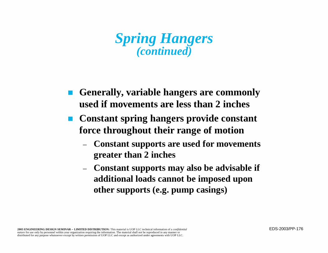
EDS-2003/PP-1762003 ENGINEERING DESIGN SEMINAR – LIMITED DISTRIBUTION: This material is UOP LLC technical information of a confidentialnature for use only by personnel within your organization requiring the information. The material shall not be reproduced in any manner ordistributed for any purpose whatsoever except by written permission of UOP LLC and except as authorized under agreements with UOP LLC.
Spring Hangers(continued)
n Generally, variable hangers are commonlyused if movements are less than 2 inches
n Constant spring hangers provide constantforce throughout their range of motion
– Constant supports are used for movementsgreater than 2 inches
– Constant supports may also be advisable ifadditional loads cannot be imposed uponother supports (e.g. pump casings)
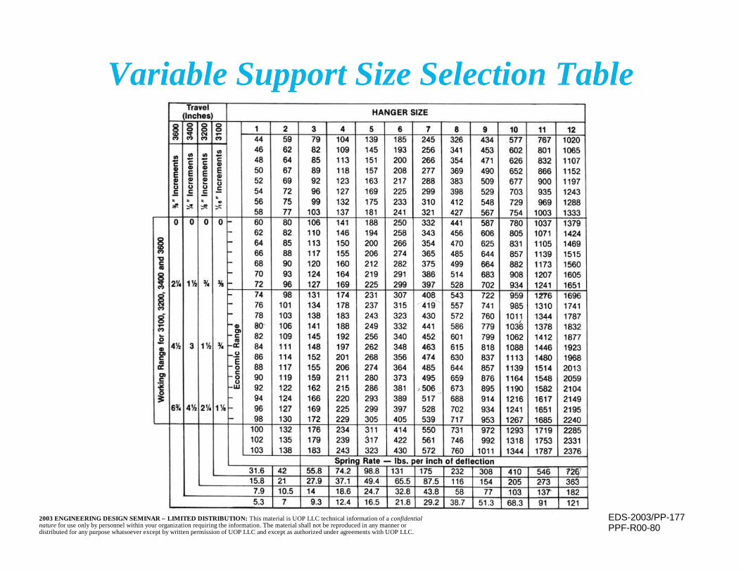
EDS-2003/PP-1772003 ENGINEERING DESIGN SEMINAR – LIMITED DISTRIBUTION: This material is UOP LLC technical information of a confidentialnature for use only by personnel within your organization requiring the information. The material shall not be reproduced in any manner ordistributed for any purpose whatsoever except by written permission of UOP LLC and except as authorized under agreements with UOP LLC.
Variable Support Size Selection Table
PPF-R00-80

EDS-2003/PP-1782003 ENGINEERING DESIGN SEMINAR – LIMITED DISTRIBUTION: This material is UOP LLC technical information of a confidentialnature for use only by personnel within your organization requiring the information. The material shall not be reproduced in any manner ordistributed for any purpose whatsoever except by written permission of UOP LLC and except as authorized under agreements with UOP LLC.
Constant Supports
PPF-R00-48
•
•
+
R
EbW
ABM
H
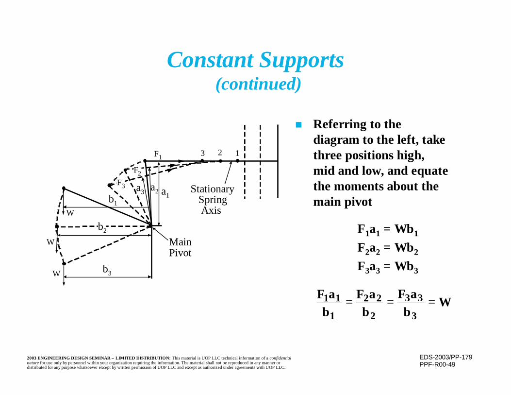
EDS-2003/PP-1792003 ENGINEERING DESIGN SEMINAR – LIMITED DISTRIBUTION: This material is UOP LLC technical information of a confidentialnature for use only by personnel within your organization requiring the information. The material shall not be reproduced in any manner ordistributed for any purpose whatsoever except by written permission of UOP LLC and except as authorized under agreements with UOP LLC.
Constant Supports (continued)
PPF-R00-49
F3
F2
F1
a3 a2 a1b1
b3
b2
W
W
W
3 2 1
Stationary Spring Axis
MainPivot
n Referring to thediagram to the left, takethree positions high,mid and low, and equatethe moments about themain pivot
F1a1 = Wb1
F2a2 = Wb2
F3a3 = Wb3
Wb
aFb
aFb
aF
3
33
2
22
1
11 ===
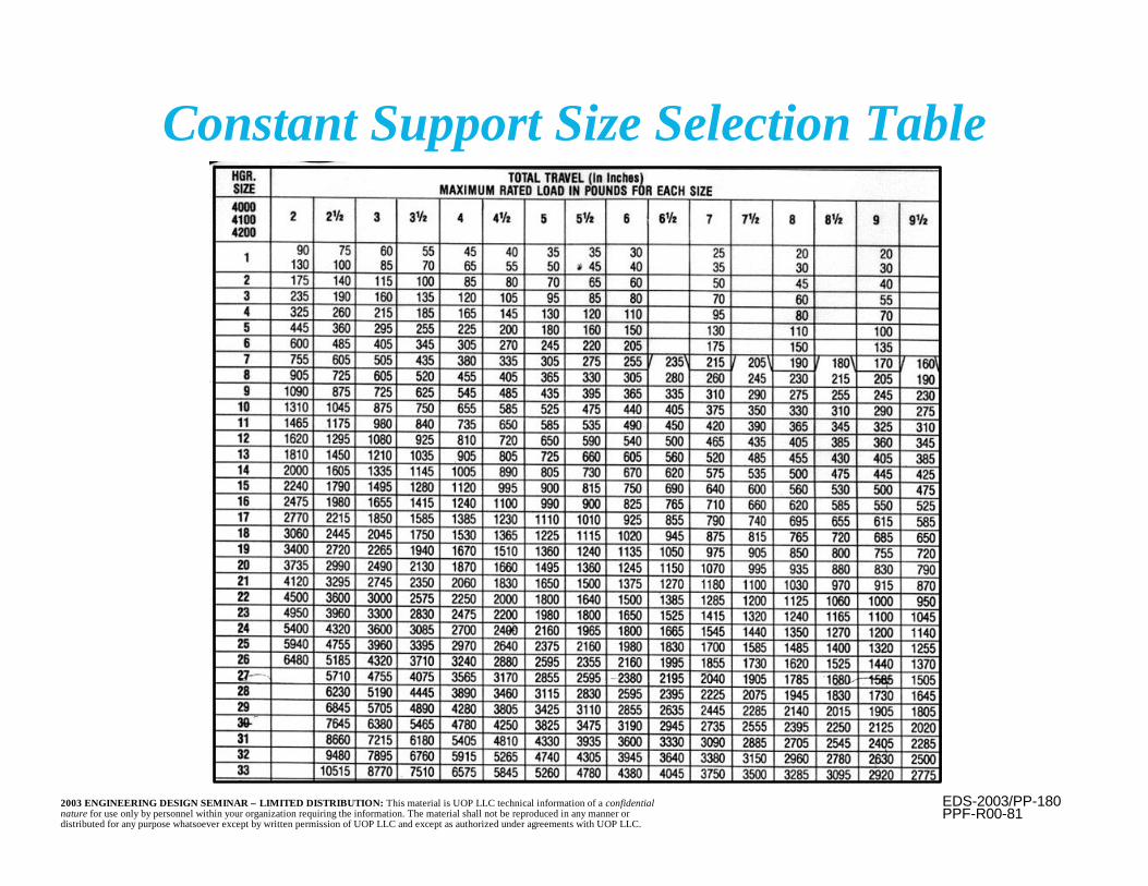
EDS-2003/PP-1802003 ENGINEERING DESIGN SEMINAR – LIMITED DISTRIBUTION: This material is UOP LLC technical information of a confidentialnature for use only by personnel within your organization requiring the information. The material shall not be reproduced in any manner ordistributed for any purpose whatsoever except by written permission of UOP LLC and except as authorized under agreements with UOP LLC.
Constant Support Size Selection Table
PPF-R00-81
EDS-2003/PP-1812003 ENGINEERING DESIGN SEMINAR – LIMITED DISTRIBUTION: This material is UOP LLC technical information of a confidentialnature for use only by personnel within your organization requiring the information. The material shall not be reproduced in any manner ordistributed for any purpose whatsoever except by written permission of UOP LLC and except as authorized under agreements with UOP LLC.
Spring Hangers(continued)
n Limited horizontal movement may beaccommodated
– Amount depends upon length of the support rod– Angle of support rod should be within 4 degrees
of vertical (constant supports may accommodatemore in the plane of the support)
EDS-2003/PP-1822003 ENGINEERING DESIGN SEMINAR – LIMITED DISTRIBUTION: This material is UOP LLC technical information of a confidentialnature for use only by personnel within your organization requiring the information. The material shall not be reproduced in any manner ordistributed for any purpose whatsoever except by written permission of UOP LLC and except as authorized under agreements with UOP LLC.
Piping Reactions
n Sometimes the equipment itself is designed to absorbsome (or all) of the unrestrained movements present atthat point in the piping system. This can serve to reducethe stress within the piping system.
n Reactions at equipment consider weight only, sustainedload, and weight plus thermal load cases
– Pressure, friction forces, etc., are considered whenconservative to do so
n Loads imposed upon vessels are normally not a concern– For large loads, specialized methods exist for determining
and evaluating the imposed stresses and deflections
EDS-2003/PP-1832003 ENGINEERING DESIGN SEMINAR – LIMITED DISTRIBUTION: This material is UOP LLC technical information of a confidentialnature for use only by personnel within your organization requiring the information. The material shall not be reproduced in any manner ordistributed for any purpose whatsoever except by written permission of UOP LLC and except as authorized under agreements with UOP LLC.
Piping Reactions(continued)
n Of more concern is overstressing or rotatingflanges, possibly causing leakage
n Attachments to rotating equipment are ofparticular concern
– Casings have a very restricted load carryingcapacity
– “Excessive” loads may distort the case– Even very small distortions may affect
operation of equipment or cause contactbetween rotor and case

EDS-2003/PP-1842003 ENGINEERING DESIGN SEMINAR – LIMITED DISTRIBUTION: This material is UOP LLC technical information of a confidentialnature for use only by personnel within your organization requiring the information. The material shall not be reproduced in any manner ordistributed for any purpose whatsoever except by written permission of UOP LLC and except as authorized under agreements with UOP LLC.
Piping Reactions(continued)
n Permissible casing loads are provided byindividual vendors
n Loads are expressed as permissiblecomponent forces and moments at inlet andoutlet or are resolved to resultant loadsrelative to the shaft

EDS-2003/PP-1852003 ENGINEERING DESIGN SEMINAR – LIMITED DISTRIBUTION: This material is UOP LLC technical information of a confidentialnature for use only by personnel within your organization requiring the information. The material shall not be reproduced in any manner ordistributed for any purpose whatsoever except by written permission of UOP LLC and except as authorized under agreements with UOP LLC.
Piping Reactions(continued)
n NEMA SM 23 provides default loads for turbines
n API 610, “Centrifugal Pumps for General RefineryServices” provides default loads for pumps
n API 617, “Centrifugal Compressors for GeneralRefinery Services” permits 1.85 times the loadspermitted by NEMA SM 23
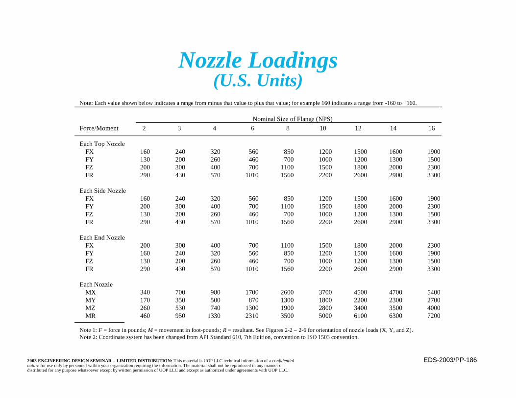
EDS-2003/PP-1862003 ENGINEERING DESIGN SEMINAR – LIMITED DISTRIBUTION: This material is UOP LLC technical information of a confidentialnature for use only by personnel within your organization requiring the information. The material shall not be reproduced in any manner ordistributed for any purpose whatsoever except by written permission of UOP LLC and except as authorized under agreements with UOP LLC.
Nozzle Loadings(U.S. Units)
Each Top NozzleFX 160 240 320 560 850 1200 1500 1600 1900FY 130 200 260 460 700 1000 1200 1300 1500FZ 200 300 400 700 1100 1500 1800 2000 2300FR 290 430 570 1010 1560 2200 2600 2900 3300
Each Side NozzleFX 160 240 320 560 850 1200 1500 1600 1900FY 200 300 400 700 1100 1500 1800 2000 2300FZ 130 200 260 460 700 1000 1200 1300 1500FR 290 430 570 1010 1560 2200 2600 2900 3300
Each End NozzleFX 200 300 400 700 1100 1500 1800 2000 2300FY 160 240 320 560 850 1200 1500 1600 1900FZ 130 200 260 460 700 1000 1200 1300 1500FR 290 430 570 1010 1560 2200 2600 2900 3300
Each NozzleMX 340 700 980 1700 2600 3700 4500 4700 5400MY 170 350 500 870 1300 1800 2200 2300 2700MZ 260 530 740 1300 1900 2800 3400 3500 4000MR 460 950 1330 2310 3500 5000 6100 6300 7200
Note: Each value shown below indicates a range from minus that value to plus that value; for example 160 indicates a range from -160 to +160.
Nominal Size of Flange (NPS)Force/Moment 2 3 4 6 8 10 12 14 16
Note 1: F = force in pounds; M = movement in foot-pounds; R = resultant. See Figures 2-2 – 2-6 for orientation of nozzle loads (X, Y, and Z).Note 2: Coordinate system has been changed from API Standard 610, 7th Edition, convention to ISO 1503 convention.
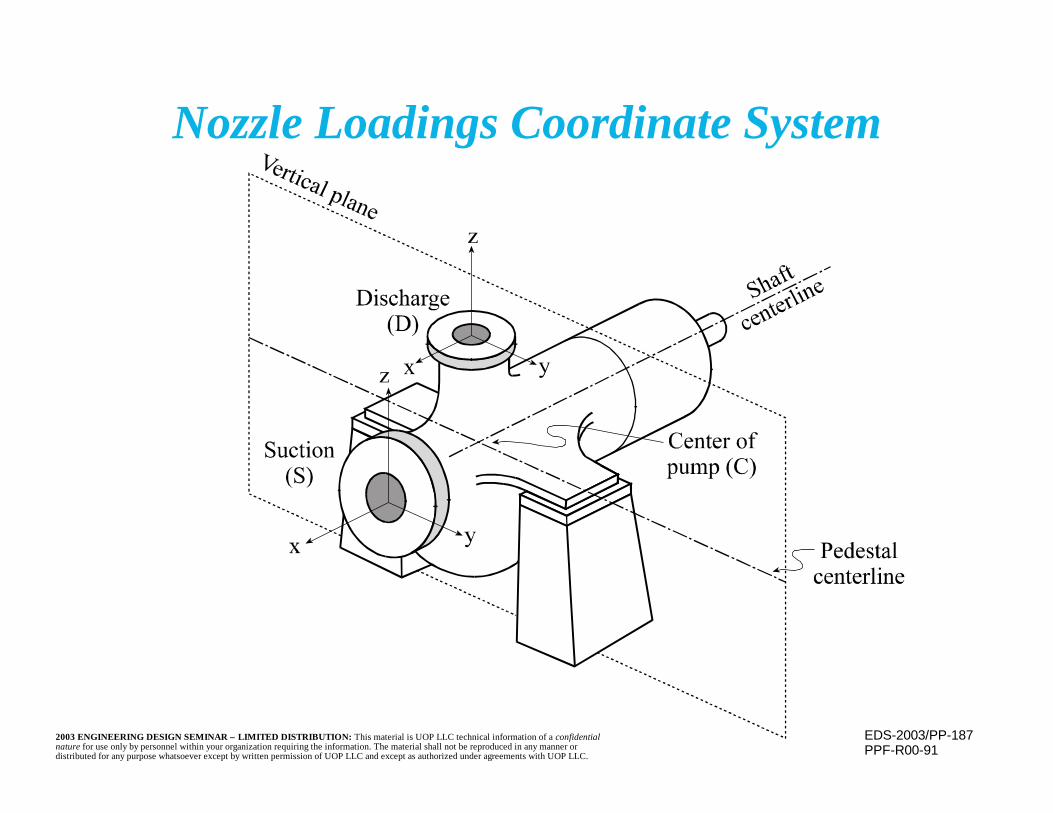
EDS-2003/PP-1872003 ENGINEERING DESIGN SEMINAR – LIMITED DISTRIBUTION: This material is UOP LLC technical information of a confidentialnature for use only by personnel within your organization requiring the information. The material shall not be reproduced in any manner ordistributed for any purpose whatsoever except by written permission of UOP LLC and except as authorized under agreements with UOP LLC.
Nozzle Loadings Coordinate System
PPF-R00-91

EDS-2003/PP-1882003 ENGINEERING DESIGN SEMINAR – LIMITED DISTRIBUTION: This material is UOP LLC technical information of a confidentialnature for use only by personnel within your organization requiring the information. The material shall not be reproduced in any manner ordistributed for any purpose whatsoever except by written permission of UOP LLC and except as authorized under agreements with UOP LLC.
Permissible Loads for Steam Turbinesper NEMA SM 23
A) At any connection:3FR + MR ≤ 500 De
FR = Resultant force (lbs)MR = Resultant moment (ft-lbs)De = Nominal connection size
(inches). If greater than 8inches, use (16+D)/3.

EDS-2003/PP-1892003 ENGINEERING DESIGN SEMINAR – LIMITED DISTRIBUTION: This material is UOP LLC technical information of a confidentialnature for use only by personnel within your organization requiring the information. The material shall not be reproduced in any manner ordistributed for any purpose whatsoever except by written permission of UOP LLC and except as authorized under agreements with UOP LLC.
Permissible Loads for Steam Turbinesper NEMA SM 23 (continued)
B) Combine resultant at centerline of exhaust1) 2FC + MC ≤ 250DC
FC = Resultant force (lbs)MC = Resultant moment (ft-lbs)DC = Diameter of the opening with
the same area as the sum ofinlet, extraction, and exhaust.If greater than 9 inches, use(18+DC)/3.
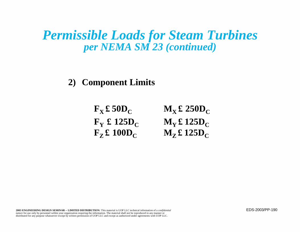
EDS-2003/PP-1902003 ENGINEERING DESIGN SEMINAR – LIMITED DISTRIBUTION: This material is UOP LLC technical information of a confidentialnature for use only by personnel within your organization requiring the information. The material shall not be reproduced in any manner ordistributed for any purpose whatsoever except by written permission of UOP LLC and except as authorized under agreements with UOP LLC.
Permissible Loads for Steam Turbinesper NEMA SM 23 (continued)
2) Component Limits
FX ≤ 50DC MX ≤ 250DC
FY ≤ 125DC MY ≤ 125DCFZ ≤ 100DC MZ ≤ 125DC
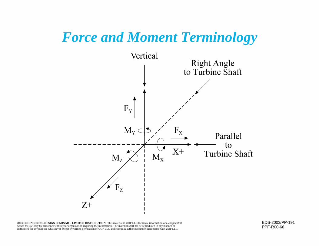
EDS-2003/PP-1912003 ENGINEERING DESIGN SEMINAR – LIMITED DISTRIBUTION: This material is UOP LLC technical information of a confidentialnature for use only by personnel within your organization requiring the information. The material shall not be reproduced in any manner ordistributed for any purpose whatsoever except by written permission of UOP LLC and except as authorized under agreements with UOP LLC.
Force and Moment Terminology
PPF-R00-66
EDS-2003/PP-1922003 ENGINEERING DESIGN SEMINAR – LIMITED DISTRIBUTION: This material is UOP LLC technical information of a confidentialnature for use only by personnel within your organization requiring the information. The material shall not be reproduced in any manner ordistributed for any purpose whatsoever except by written permission of UOP LLC and except as authorized under agreements with UOP LLC.
Cold Spring
n Cold spring is the intentional, cold, deflectionof the piping in a direction opposite to thedirection of thermal movement, imposingopposite stresses
n First part of thermal movement will bethrough this deflected range
– Results in a smaller net deflection and lowerstress magnitudes
– Less strain during initial deflection– Similar to camber provided in some beams

EDS-2003/PP-1932003 ENGINEERING DESIGN SEMINAR – LIMITED DISTRIBUTION: This material is UOP LLC technical information of a confidentialnature for use only by personnel within your organization requiring the information. The material shall not be reproduced in any manner ordistributed for any purpose whatsoever except by written permission of UOP LLC and except as authorized under agreements with UOP LLC.
Cold Spring(continued)
n Effects of cold spring may only be consideredfor reaction loads
– Piping stresses are compared to a stress range(maximum - minimum), which is not affectedby the cold spring
– Reactions, on the other hand, consider theabsolute value of the load
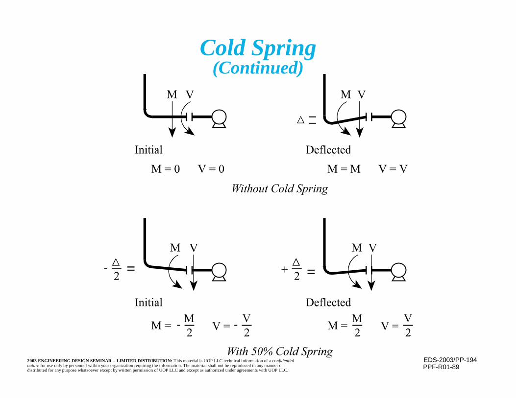
EDS-2003/PP-1942003 ENGINEERING DESIGN SEMINAR – LIMITED DISTRIBUTION: This material is UOP LLC technical information of a confidentialnature for use only by personnel within your organization requiring the information. The material shall not be reproduced in any manner ordistributed for any purpose whatsoever except by written permission of UOP LLC and except as authorized under agreements with UOP LLC.
Cold Spring(Continued)
PPF-R01-89
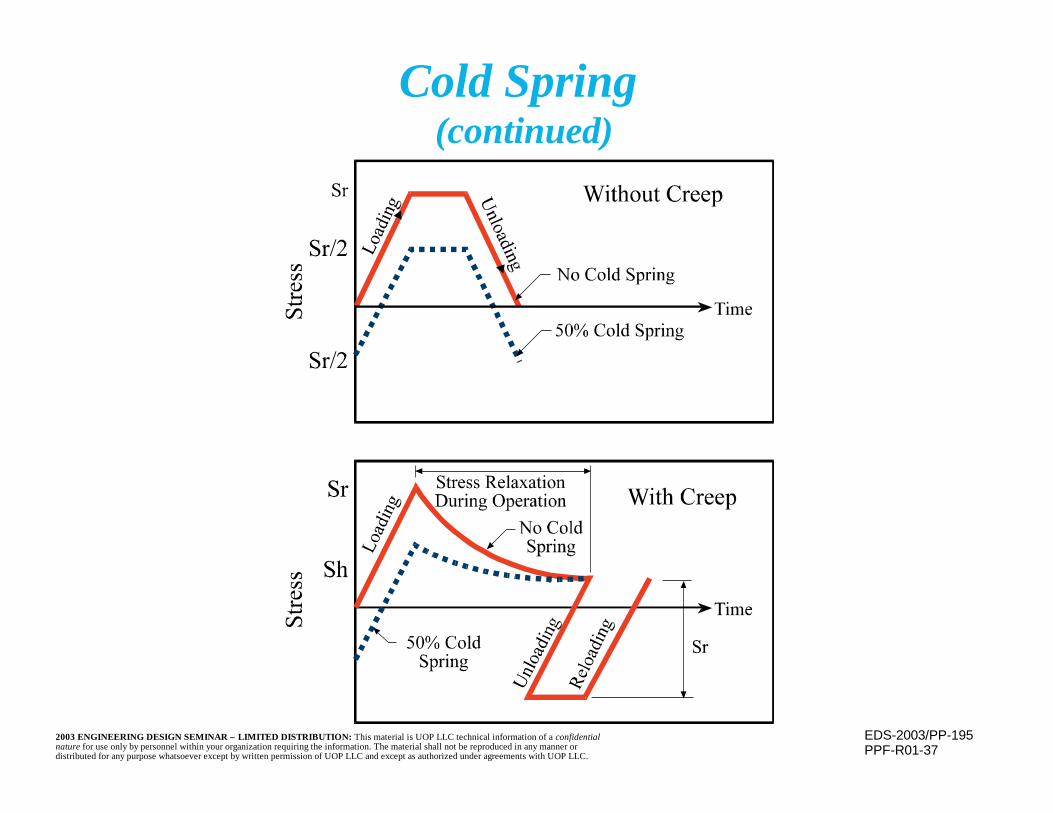
EDS-2003/PP-1952003 ENGINEERING DESIGN SEMINAR – LIMITED DISTRIBUTION: This material is UOP LLC technical information of a confidentialnature for use only by personnel within your organization requiring the information. The material shall not be reproduced in any manner ordistributed for any purpose whatsoever except by written permission of UOP LLC and except as authorized under agreements with UOP LLC.
Cold Spring (continued)
PPF-R01-37
EDS-2003/PP-1962003 ENGINEERING DESIGN SEMINAR – LIMITED DISTRIBUTION: This material is UOP LLC technical information of a confidentialnature for use only by personnel within your organization requiring the information. The material shall not be reproduced in any manner ordistributed for any purpose whatsoever except by written permission of UOP LLC and except as authorized under agreements with UOP LLC.
Cold Spring(continued)
n Because of difficulties in insuring the proper coldspring is actually present, the Code allowsconsideration of only 2/3 of the intended coldspring
n When installing a cold spring, care must betaken to insure that piping still slopes in theintended direction
n Ensure that the flanges may still be bolted upwithout excessive difficulty (cold spring mayintroduce a cold misalignment)

EDS-2003/PP-1972003 ENGINEERING DESIGN SEMINAR – LIMITED DISTRIBUTION: This material is UOP LLC technical information of a confidentialnature for use only by personnel within your organization requiring the information. The material shall not be reproduced in any manner ordistributed for any purpose whatsoever except by written permission of UOP LLC and except as authorized under agreements with UOP LLC.
Cold Spring(continued)
n Deformation must be a stress-strain imposingdistortion (e.g. fabricating one leg short andpulling the other leg to mate), not a no stressor strain “off line” fabrication
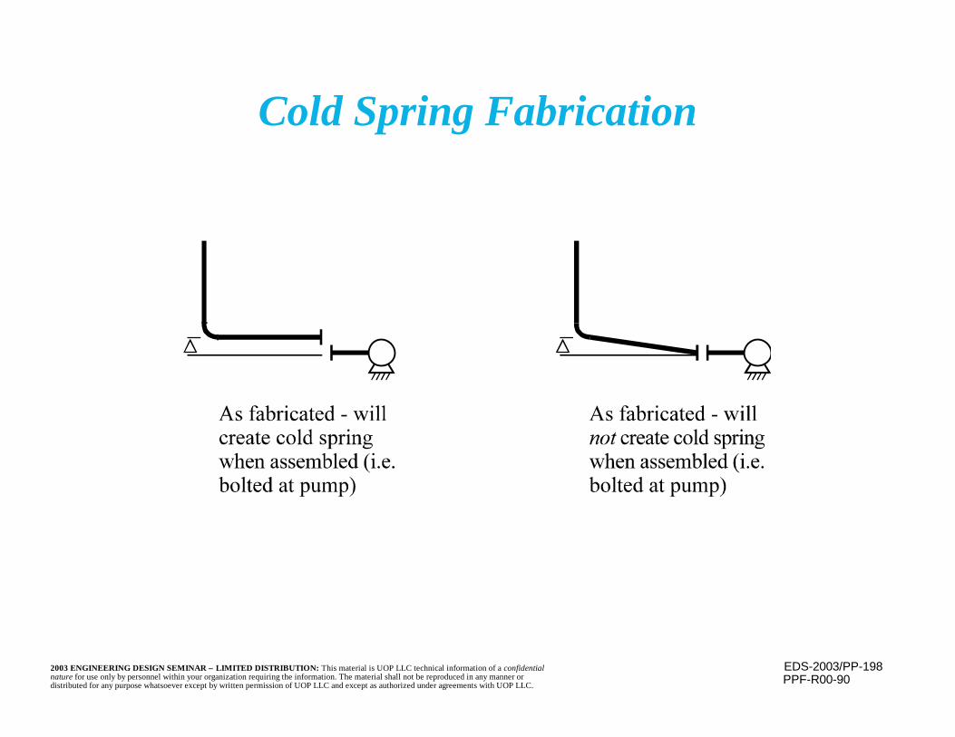
EDS-2003/PP-1982003 ENGINEERING DESIGN SEMINAR – LIMITED DISTRIBUTION: This material is UOP LLC technical information of a confidentialnature for use only by personnel within your organization requiring the information. The material shall not be reproduced in any manner ordistributed for any purpose whatsoever except by written permission of UOP LLC and except as authorized under agreements with UOP LLC.
Cold Spring Fabrication
PPF-R00-90

EDS-2003/PP-1992003 ENGINEERING DESIGN SEMINAR – LIMITED DISTRIBUTION: This material is UOP LLC technical information of a confidentialnature for use only by personnel within your organization requiring the information. The material shall not be reproduced in any manner ordistributed for any purpose whatsoever except by written permission of UOP LLC and except as authorized under agreements with UOP LLC.
Flue Gas LineIsometric
PPF-R01-70