prestressed concrete highway bridges 1n the federal...
TRANSCRIPT

64
have been awarded to Kiewit-Grice and Moseman Construction.
It is estimated that the cost impact of the more refined seismic design is limited almost entirely to a small increase in design effort. This additional design effort is a small price to pay for the increased ability of this major structure to survive a major seismic event.
REFERENCES
1. S.T. Algermissen and S.T. Harding. The Puget Sound Earthquake of Apr i1 29, 1965. Preliminary Seismological Report. u.s. Coast and Geodetic Survey, Washington, D.C., 1965.
2. N .M. Newmark and W .J. Hall. Earthquake Spectra and Design Engineering. Earthquake Engineering Research Institute, Berkeley, Calif., 1982.
3. Highway Bridge Design Brief. MWD Publication CDP 7-02/D. New Zealand Ministry of Works and Development, Wellington, 1978.
Transportation Research Record 982
4. Seismic Design Guidelines for Highway Bridges. ATC-6. Applied Technology Council, Berkeley, Calif., 1981.
5. H.E. Chapman. An Overview of the State of Practice in Earthquake Resistant Design of Bridges in New Zealand. Proc., Workshop on Earthquake Resistance of Highway Bridges, Report ATC-6-1, Applied Technology Council, Palo Alto, Calif., 1979.
6. A.S. Veletsos and N.M. Newmark. Effect of Inelastic Behavior on the Response of Simple Systems to Earthquake Motions. Proc., Second World Conference on Earthquake Engineering, Tokyo and Kyoto, Japan, 1960.
7. R. Park and T. Paulay. Reinforced Concrete Structures. Wiley, New York, 1975.
Publication of this paper sponsored by Committee on Dynamics and Field Testing of Bridges.
Prestressed Concrete Highway Bridges 1n the Federal Republic of Germany-
Construction Methods and Experiences KURT RAHLWES
ABSTRACT
Approximately 63 percent of all bridge surf aces on federal highways in the Federal Republic of Germany consist of prestressed concrete built since 1950. In a short period of time a large volume of work has been accomplished using a new method of construction. Most of the structures meet fully all serviceability, durability, and functional standards with an acceptable maintenance outlay. A few negative experiences could, however, not be avoided. Their causes were faults in design and construction, as well as weak points in the technical regulations, which formed the basis for the design. This report describes the construction principles used in prestressed road bridges, the faults and damage that occurred, and the measures taken to avoid them.
In 1980 approximately 30 percent of the 27,000 bridges in the federal highway and freeway system of west Germany were prestressed concrete bridges <1>·
This constitutes about 63 percent of the total bridge surface area. Almost all of these prestressed concrete bridges have been built since 1950.
TENDER AND BIDDING PROCEDURE
The client, generally a government agency, works out a design that comprises the technical boundary conditions. The required services and quantities are established on the basis of a preliminary analysis. When the contract is awarded, the contractor, in addition to the actual construction, has to supply and take responsibility for the final structural analysis and the shop drawings. All design documents are checked to the last digit and approved by a federally licensed independent engineer. Construction is continuously supervised by staff of the transportation department. Payment is generally based on unit prices.
In addition to bidding on the original design, the contractor generally has the option of submitting an alternative design. He is responsible for submitting complete and binding quantities and services with the design. When a contract is awarded for a design, payments are made based on unit prices and required material quantities but only up to the total sum submitted in the bid. Approximately 75

Rahlwes
percent of all bridges are built according to alternative designs.
CONSTRUCTION METHODS
Precast girders, either pretensioned in casting beds or post tensioned with subsequent bonding, are used primarily with cast-in-place top slabs for bridges over existing roadways. This system is also used for multispan bridges. Maximum spans of up to 160 ft c~so m) can be accomplished with this method.
The girders are placed in position by mobile cranes or specially designed launching gantries. They can also be manufactured in situ, for example, by the Schreck method with transverse movable selfsupporting scaffolding or by means of traveling falsework. In the latter case, the formwork is stationary during the construction of a particular span and the girders are placed sideways in their final position by movable portal cranes at the bents (Figure 1).
Production of precast girder
~..&.~W2A~C
~ 11 reinlorcem1mt
I- ~:' R wyqyyyydd.w;;; ~J;. ... . 1
concreting of top slab
2 Longitudinal launching of travelling falsework p,.,.,.,,,.~
- r . t ~*™1 J ' nm· ~ · 1 2
w FIGURE 1 Precast girder bridges erected with traveling falsework.
For small girder spacings the upper flanges of the precast girders are used as formwork for the cast-in-place top slab, and for more widely spaced girders additional precast concrete panels or movable formwork are employed. The difference in age between the precast girders and the cast-in-place top has to be considered in the design.
Statically determinate spans are used for up to 130 ft (~40 m) where the joint between the individual spans is generally covered by a continuous top slab {Figu r e 2) • To allow for sufficient flexibility in this continuous top slab, a soft intermediate layer between the precast girders and the top slab is provided in the vicinity o f the joint. This flexib le slab bas to be designed for all external loads as well as all deformations in the adjacent spans. A main design criterion is the control of crack width. This construction method is very economical in this formi however, piers or bents reaching over the entire width of the bridge section with a lar ge nuJ1lber of individual bearings are required.
Cont inuous bridge structures can be built with precast girders by joining them monolithically by diaphragms cast in place with the top slab (Fig1,1 re 3). The top s lab reinforcement, usi'rig either rebars
j;;;;;;;;;;~~~;:;;;;;;;;;;:~~c i p concrete
cross girder !optional)
Cross-Section
. .:..precast girder
for hydraulic jacks
\ pre ca st girder
'"~ ''''"-M1f[ !optional) I ,
l
FIGURE 2 Reinforced concrete slab over joint between two spans.
re i.p concrete
I [precosl girder
FIGURE 3 Span-by-span construction with precast girders-section through main girder and cross girder.
65
or prestressing, is designed for negative support moments at the bents.
Both alternatives of this construction method with p recas t girders feature relatively small main girder spacings in order to minimize or to e liminate the formwork for the cast-in-place top slab and to reduce self-weight. This last objective is achieved in many cases by reducing the web thickness and providing bottom flanges for the precast girders. This results in complex cross sections with large surface areas and edges exposed to potentially aggressive environmental conditions.
A majority of prestressed concrete bridges are built as statically indeterminate, continuous, monolithic, cast-in-place structures. For spans of up to 100 ft (~30 m), solid or voided slabs are most common. For spans longer than 100 ft (~30 m), Tgicder or box-girder sections are generally used. Total monolithic lengths of more than 3,300 ft c~1000 m) have been achieved.
There are a number of advantages to these continuous bridge structures over simple-span structures. First, they feature higher structural safety due to internal force redistribution capabilities. Their deformations are smaller and continuous, which improves the dynamic aspects and dr i ving condition of the road surface. Fewer though heavier bearings are required and can be installed with good accessi-

66
bility for easy maintenance. The number of construction joints and expansion joints that require servicing and maintenance is smaller. Continuous monolithic structures adapt more easily to complex geometric and aesthetic forms. Finally, large spans can only ue l>r idged satisfactorily with continuous structures. The disadvantage of continuous structures lies in their higher sensitivity to temperature effects and support settlements, which have to be accounted for by an appropriate design.
Bridges of only o. few spans and shorL ove1all length are generally concreted in one pour on falsework and posttensioned with tendons that are subsequently grouted. Longer bridge structures and multispan structures are concreted in sections (Figure 4). The postbonded tendons are connected with cou-
p s; n ~ formwor k
FIGURE 4 Sectional construction of continuous posttensioned concrete bridges.
plers at the construction joints (Figure 5) • The present level of development of monolithic sectional construction with scaffolding was reached with the introduction of traveling falsework. The formwork and metal scaffolding travel, supported by special shoring piers, as a unit from one construction sec-
12 strands with 0,6" diameter
Section a-a
j~a ""-high strength bolts
FIGURE 5 Coupling of prestressing tendons with 12 x 0.6 in. strands.
tion to the next (Figures 6 and 7). The economical use of this traveling falsework requires special cross sections that should be uniform over the entire bridge length.
The double webbed T-girder without diaphragms supported by individual piers meets this requirement best. The formwork and the metal scaffolding units can be removed and can travel to the next construction section quite easily. Another advantage of this type of cross section is that the main girder rein-
Transportation Research Record 982
Concreting stage
Longitudinal launching of tormwork -FIGURE 6 Traveling falsework without intermediate supports.
Concreting stage Launching stage
FIGURE 7 Traveling falsework for double T-girder sections.
• -
forcement can be prefabricated and placed as a large reinforcement cage. Box-girders can also be built with traveling falsework with some additional effort for formwork and concreting. Box-girders offer the advantage of readily providing space for service and inspection. The disadvantages of box-girder sect ions, in addition to increased difficulties in concreting, are the larger changes in internal forces, due to cracking of the concrete, that do not occur to the same extent in T-girder sections. The influences of temperature, differential creep, and shrinkage are more complex and, in some cases, more severe.
The incremental launching method developed by F. Leonhardt is a shoring-free construction method for multiple-span prestressed concrete superstructures. The principle is based on the segmental fabrication of the superstructuy;e in a stationary construction pit located behind one of the abutments and the incrementa l longitudinal launching of the superstructure by means of hydraulic jacks as each segment is completed. During launching, the superstructure slides on temporary sliding bearings that are installed on the piers or, for large spans, on auxiliary steel or concrete piers (Figure 8). The superstructure is centrically prestressed with tendons distributed uniformly over the cross section and coupled at the construction joints to account for the variation of internal forces during launching. A light steel launching nose tensioned to the front end of the superstructure is used to reduce cantilever bending moments. In addition to the centrical prestressing for the launching stages, tendons are placed in embedded ducts following the moment distribution of the finished bridge structure. They are tensioned when the superstructure has reached its final position. At that stage the temporary sliding bearings are removed and the permanent bearings in-

Rahlwes
sl iding bearing
longitudinal launching device
~p~
~ FIGURE 8 Principle of incremental launching method.
stalled while the superstructure is jacked up hydraulically.
The first bridges built with the incremental launching method were of the box-girder type. Since then, however, the double webbed T-girder has proved to be competitive because of the simple construction process. Another advantage of the T-girder is its small torsional stiffness. The T-girder can adapt easily to the forced deformations caused by inaccuracies in the level of the sliding bearings and the bottom of the superstructure, which are encountered during the launching process.
The incremental launching method can also be adapted for curved bridges as long as the radii of curvature in plan and in elevation are constant or nearly constant.
Another shoring-free construction method for continuous, prestressed, concrete bridges is the castin-place cantilever construction method that was developed by Finsterwalder and that is primarily used for large-span, beam-type bridges. To date, the bridge with the longest span built this way is the Koror Bridge that connects two smaller islands near the island of Guam. The span is 790 ft (241 m) long. The most important recent application of this method in West Germany was the construction of the Kochertal Bridge with spans of up to 452 ft (138 m) and a total monolithic length of 3,700 ft (1128 m). The box-type center of the cross section (Figure 9) was erected using the cast-in-place cantilever
101°
FIGURE 9 Cross section of Kochertal bridge.
67
method, and subsequently the cantilevering portions of the top slab were cast up to a total deck width of 100 ft (30.5 m) by traveling formwork and supported by inclined struts.
Extensive experience with the cantilever construction method using precast segments does not exist in West Germany. However, a few bridges of this type have been erected by German contractors abroad.
EXPERIENCES
To point out mistakes that have been made and how they can be avoided it is necessary to elaborate on the negative experiences. It must, however, be emphasized beforehand that most prestressed concrete bridges in West Germany meet fully all serviceability, durability, and functional standards. When the proper servicing and maintenance are provided for these bridges, no serious doubts exist about the life expectancy, which ranges from 50 to 80 years, of these structures. Wearing parts such as surfacing, curbs, and sidewalks as well as expansion joints inevitably have to be repaired at shorter intervals. It is also important to note that so far there have been no deaths or injuries caused by failure in service of prestressed concrete bridges.
GENERAL INFORMATION
The concrete grade normally used is B 45, which means a minimum 28-day cube strength of 45 MN/m' that corresponds to more than 5,000 psi 28-day cylinder strength. The reinforcing steel generally co~sists of deformed bars of grade BSt 420/500, which corresponds to a grade 60 steel.
There has been no long-term experience with epoxy-coated rebars or with other corrosion protect ion for the reinforcement in West Germany.
Typically prestressing steels used during the last 10 years have been high-strength alloy bars with a maximum diameter of 1.40 in. (36 mm) and an ultimate strength of 154 ksi ( 1080 N/mm') or O. 6-in .-diameter strands with a minimum strength of 250 ksi (1770 N/mm 2). Most bridges incorporate transversely prestressed top slabs and diaphragms.
By far the larger number of bridge structures was provided with asphalt surfacing (Figure 10) 1.5-2. 5 in. (4-6 cm) thick, which consisted of protection and wearing layers on top of a waterproofing layer covering the entire bridge surface. This waterproofing used to consist of glued aluminum or copper foils, but it is now made up of a 0.4 in. (1 cm) thick asphalt mastic layer on top of a glassfleece sheet for vapor pressure ventilation. The waterproofing is directly connected to the drain inlets
parapet
drain inlet
FIGURE 10 Typical cross section of road bridge.
68
to allow drainage of seepage water. Recently the concrete surface under the waterproofing has been treated with an epoxy-based sealant as an additional barrier to prevent penetration of chlorides from deicing salts. The heavy use of deicing salts also led to the construction of curbs, sidewalks, and facia beams in one unit using air-entrained concrete.
DEFECTS AND DAMAGE
There are two reasons for that have been encountered:
the defects and damage the violation of corn-
manly known technical rules in design and execution at the time of construction and weak points in these rules at the time.
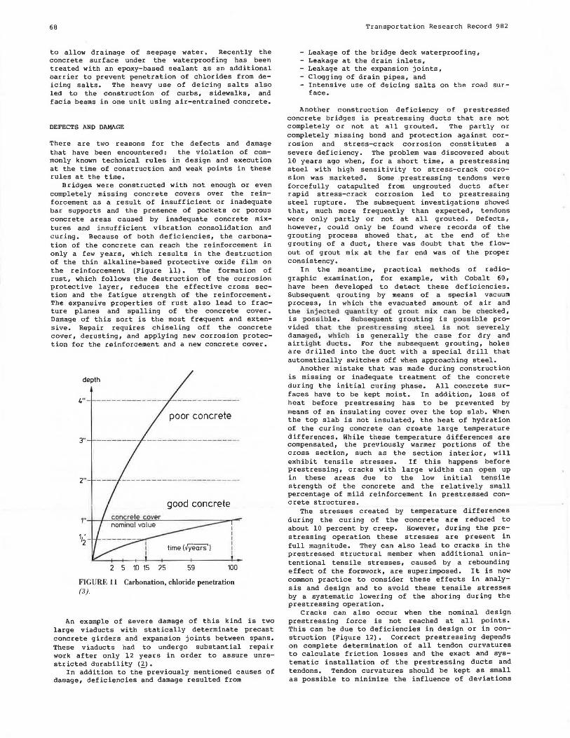
Bridges were constructed with not enough or even completely missing concrete covers over the reinforcement as a result of insufficient or inadequate bar supports and the presence of pockets or porous concrete areas caused by inadequate concrete mixtures and insufficient vibration consolidation and curing. Because of both deficiencies, the carbonation of the concrete can reach the reinforcement in only a few years, which results in the destruction of the thin alkaline-based protective oxide film on the reinforcement (Figure 11). The formation of rust, which follows the destruction of the corrosion protective layer, reduces t he effective cross section and the fatigue strength of the reinforcement. The expansive properties of rust also lead to fracture planes and spalling of the concrete cover. Damage of this sort is the most frequent and extensive. Repair requires chiseling off the concrete cover, derusting, and applying new corrosion protection for the reinforcement and a new concrete cover.
depth
4" -----------
poor concrete
3"
good concrete
time (Jyears'J
2 5 10 15 25 59 100
FIGURE 11 Carbonation, chloride penetration (3).
An example of severe damage of this kind is two large viaducts with statically determinate precast concrete girders and expansion joints between spans. These viaducts had to undergo substantial repair work after only 12 years in order to assure unrestricted durability (2).
In addition to the-previously mentioned causes of damage, def i ciencies and damage resulted from
Transpor t a tion Re s earch Record 982
- Leakage of the bridge deck waterproofing, - Leakage at the drain inlets, - Leakage at the expansion joints, - Clogging of drain pipes, and - Intensive use of deicing salts on the road sur-
f ace.
Another construction deficiency of prestressed concrete bridges is prestressing ducts that are not completely or not at all grouted. The partly or completely missing bond and protection against corrosion and stress-crack corrosion constitutes a severe deficiency. The problem was discovered about 10 years ago when, for a short time, a prestressing steel with high sensitivity to stress-crack corrosion was marketed. Some prestressing tendons were forcefully catapulted from ungrouted ducts after rapid stress-crack corrosion led to prestressing steel rupture. The subsequent investigations showed that, much more frequently than expected, tendons were only partly or not at all grouted. Defects, however, could only be found where records of the grouting process showed that, at the end of the grouting of a duct, there was doubt that the flowout of grout mix at the far end was of the proper consistency.
In the meantime, practical methods of radiographic examination, for example, with Cobalt 60, have been developed to detect these deficiencies. Subsequent grouting by means of a special vacuum process, in which the evacuated amount of air and the injec t ed q ua nti t y o f g r ou t mix can be c hecked, is possible. Subsequent g r outing is poss i ble provide d t hat the prestressing steel is not severely damaged , which is generally the case for dry and airt ight d ucts . For the subseque nt grouting, holes are drilled into the duct with a special drill that automatically switches off when approaching steel.
Another mistake that was made during construction is missing or inadequate treatment of the concrete during the initial curing phase. All concrete surfaces have to be kept moist. In addition, loss of heat before prestressing has to be prevented by means of an insulating cover over the top slab. When the top slab is not insulated, the heat of hydration of the curing concrete can create large temperature differences. While these temperature differences are compensated, the previously warmer portions of the cross section, such as the section interior, will exhibit tensile stresses. If this happens before prestressing, cracks with large widths can open up in these areas due to the low initial tens ile strength of the concrete and the relatively small percentage of mild reinforcement in prestressed concrete structures.
The stresses created by temperature differences during the curing of the concrete are reduced to about 10 percent by creep. However, during the pres tressing operation these stresses are present in full magnitude. They can also lead to cracks in the prestressed structural member when additional unintentional tensile stresses, caused by a rebounding effect of the forrnwork, are superimposed. It is now common practice to consider these effects in analysis and design and to avoid these tensile stresses by a systematic lowering of the shoring during the prestressing operation.
Cracks can also occur when the nominal design prestressing force is not reached at all points. This can be due to deficiencies in design or in construction (Figure 12). Correct prestressing depends on complete determination of all tendon curvatures to calculate friction losses and the exact and systematic installation of the prestressing ducts and tendons. Tendon curvatures should be kept as small as possible to minimize the influence of deviations

Rahlwes
a:., ex. 2
ZI FE~~-~ Ol3 - 014
-µ · ~CX:
Fd =FA· e (design)
---real
-~µ , IC(
Fr I Fd = e (real)
mllllll I~ ex. 90° 60° 30° 0
FIGURE 12 Friction losses.
in the friction coefficients. Corrosion of the prestressing steel, especially smooth high-strength wires and strands, and of the prestressing ducts can significantly increase the friction coefficients. Corrosion damage to the prestressing steel can lower its fatigue strength and can be the origin of stress-crack corrosion in the tensioned but ungrouted state. Prestressing steel and ducts should, therefore, be kept protected against corrosion and installed quickly.
One of the most frequent violations of the common rules of technical knowledge in design is cross sect ion dimensions that are too small. They result in reinforcement and prestressing steel concentrations that complicate the placing of the concrete, which in turn leads to the formation of pockets and inadequately vibrated concrete zones. Similar consequences can result from complex cross sections and poor detailing. Another design mistake is not making stress checks at all relevant sections. Areas in the vicinity of the supports of continuous girders can be critical especially when temperature effects are neglected.
In general, however, it should be noted that the system of using federally licensed independent engineers to check the complete design eliminates, to a large extent, mistakes in the design. One of the unfortunate exceptions is a bridge in BerlinSchmargendorf that was built in 1960 with an overall length of 754 ft (230 m). The bridge was extensively repaired in 1970 but had ultimately to be removed due to the overall lack of safety of the structure (~).The damage resulted from construction deficiencies (about 1/5 of the tendons were not properly grouted) ; from weak points in the construction and building codes valid at that time; and especially from severe mistakes in the structural analysis, particularly in the shear design. In addition, the cross section caused difficulties in concreting.
The second category of reasons for deficiencies in pres tressed concrete bridges is weak points in the building and construction code provisions valid at the time of application. For a better understanding, a short history of the development of the most important code prov is ions for pres tressed concrete bridges in West Germany is useful. The first.
69
German building code for prestressed concrete was introduced in 1953. Since 1953 the allowable service stress in prestressing steel has been retained at the low level of 75 percent of the yield strength or 55 percent of the ultimate strength. This generally leads to certain reserves in the theoretical ultimate load state and the possibility of correcting unexpectedly high friction losses during the prestressing operation by means of overstressing, for example, up to 90 percent of the yield strength.
The code provisions for permissible concrete tensile stresses using limited prestressing, which has been used for most of the road bridges, were also retained. The code provision stipulates that no flexural tension due to dead load and 1/2 x live load may occur. Under full live load and dead load, flexural tensile stresses of the magnitude of the tensile strength of the concrete are permitted. It should be noted here that the check on concrete tensile stresses can be very sensitive for slender, large-span bridges because of inaccuracies resulting from differences of large numbers.
The German prestressed concrete code of 1953 allowed the control of crack width by means of a stress check in the mild reinforcement assuming a cracked section. Under service loads, the reinforcement stresses were limited to the usual service stress criteria, and under loads factored by 1.35 the limit was set by the yield stress. Yielding of the prestressing reinforcement was not permitted. In design practice, however, reinforcement was often provided to cover the nominal concrete tensile forces. Only since 1979 have additional crack width control provisions been required. Because the load safety factor of 1.35 is meaningless in the vicinity of the point of contraflexure, this criterion will be replaced by an additive safety term. Even now the analytic check on crack width is questionable. The formulas for the prediction of crack width used in different countries can yield very different results. Reality is not always predicted satisfacsatisfactor ily.
Requirements for minimum reinforcement ratios did not change until 1973 (Figure 13). For example, grade 60 deformed bars in the longitudinal direction of a girder web had to be provided to at least 0.15 percent of the concrete area. Later this ratio was raised to 0.4 percent for approximately 5,000 psi (grade B 45) concrete. In addition, the minimum re-
1953to1973
since 1973 (845)
FIGURE 13 Minimum reinforcement requirements.

70
inforcement ratios are now linked to the concrete grade.
Before 1966 no minimum reinforcement requirement for shear existed. Nominal shear reinforcement was to be provided in all areas wherP. thP.oretical principal tensile stresses under factored ultimate loads did not exceed the tensile strenqth of the concrete. Frequently this rule was misinterpreted leading to cross-sectional dimensions that barely met this requirement and, thus, resulted in an underrP.inforced shear design.
The minimum reinforcement cover was increased in several steps from 0.8 in. (2 cm) in 1953 to 1.4-1.6 in. (3.5-4 cm) now, depending on environmental conditions.
Temperature differences between the top and the bottom face of a structural member were generally not taken into account before 1979. Now superstructures with asphalt surfacing have to be analyzed for a temperature difference of 9°F ( 5°C) super imposed on the most unfavorable condition caused by live loads.
Significant changes in the design for coupling joints of sectionally erected prestressed concrete bridges were introduced in 1977. Reasons for doing so were the frequent occurrence of cracks in the vicinity of coupling joints and especially the rupture of tendons in the bottom flange of a box-girder bridge near Duccoeldorf. The overall stability and safety of the structure were no longer guaranteed and could only be restored with auxiliary supports and reduced allowable traffic loadings (~). Now the bridge has been repaired and reopened to regular traffic (Figure 14).
coupling joints with ruptured preslressing bars
Principle sketch ot repair works with
cxJditional longitudinal prestressing
Anchorage of additional longitudinal presfressing at the end ot the bridge
~~:=lendoos ~rkeys
J· ! I I i-t..-1' , 1 1 • box girder web transverse prestressing lendOns
FIGURE 14 Repair of bridge near Duesseldorf (2).
An investigation of all other bridges with coupling joints showed that by the end of 1980 about 21 percent of all structurP.s with T-girdP.r cross sections and 41 percent of the structures with boxg irder cross sections exhibited cracks with widths of more than 0.008 in. (0.2 nun) in the vicinity of coupling joints. It had to be decided if sufficient corrosion protection would be maintained by simply injecting the cracks with epoxy resin or if other measures would have to be taken because the cracks led to high cyclic wear on the couplers of the tendons, whose fatigue strength is lower than the fatigue strength of the tendons themselves.
These incidents stirred up considerable public attention and gave rise to er itical considerations of the durability and safety of these types of bridge structures. Intensive investigations of the
Transportation Research Record 982
Duesseldorf bridge showed that cracks of up to 0. 0 8 in. (2 nun) had formed in the bottom flange due to the fact that the design concrete compression stress level was not reached. This resulted in higher fatigue loadings and corrosion of the temluns, which led to their subsequent rupture. It became obvious that a numbP.r of causes can trigger such a phenomenon. The most important ones are
- Temperature differences, which were not considered in the design, between the top and bottom face of a structural member;
- Inaccuracies in determining bending moments due to dead load and prestressing in the vicinity of the points of contraflexure where coupling joints are usually located; these can also be caused by inexactly known moment redistributions due to creep; Increased loss of prestressing force in the area of coupling joints caused by creep and larger steel cross sections of the tendon couplers;
- Nonlinear stress distributions due to tendon anchorages in the coupling joints; and
- Inadequate tendon forces at the coupling joints due to unfavorable friction conditions.
Certainly this does not conclude the list of encountered defects, damage, and deficiencies. Alkalireactive expansive aggregates, unsuitable concrete additives, the already mentioned oversensitive prestressing steel, and other problems should be pointed out. However, they constitute special phenomena that, when understood, should not be repeated.
EFFECTS OF CRACKS
It is generally agreed that, because of the wide spread of concrete tensile strengths and the various temperature effects starting at construction, prestressed concrete bridges cannot be built compl~tely without cracks. The risk potential of cracks in prestressed concrete bridges is twofold. Where cracks can propagate through the concrete section, the cyclic wear in mild and prestressed reinforcement increases (Figure 15). In the area of prestressing
Os tension
6s Fd=design prestressing
force
concrete ten -Sile Strength-
minM
compression FIGURE 15 Stress deviations in the reinforcement due to live loads.
M

Rahlwes
tendon couplings, which are sensitive to cyclic loading, an appropriate design, especially by means of increased mild reinforcement, has to reduce the effects of cracks to an acceptable level. The investigations of the damage to coupling joints have also shown that not all cracks visible at the concrete surface have led to higher cyclic wear in the reinforcement. Cracks that do not propagate deep into the cross section hardly change the cyclic load characteristics with respect to the uncracked stage. The condition of existing structures can only be determined by measuring the changes in crack width under varying loadings.
The second risk, originating from cracks, is the danger of corrosion. All design rules have in common the avoidance of few and large cracks in favor of more cracks with smaller crack widths. Cracks up to 0.008 in. (0.2 mm) wide are considered harmless under conditions prevailing with bridges. However, Soretz claimed in 1967 that crack width does not have the assumed effect on corrosion of the reinforcement as long as the concrete cover has sufficient depth and the concrete is properly mixed and consolidated. He based his findings on extensive investigations of reinforced concrete bridges in several European countries. Recent investigations by Schiessl (3) based on long-term outdoor experiments and a report by Rostam (4) on more than 2, 000 partially prestressed bridges in Denmark seem to substantiate this opinion. Finally, day-to-day experience with reinforced concrete structures has also shown that not so much the crack width, as long as 0.02 in. (0.5 mm) is not exceeded, but rather the depth and quality of the concrete cover determine the susceptibility to corrosion.
Especially under the influence of deicing salts, a proper design, a flawless construction, and a continuous maintenance of the waterproofing and drainage installations are fundamental.
RESULTS
So far, no comprehensive report on the condition of the prestressed concrete bridges in West Germany exists. The yearly costs for maintenance, rehabilitation, and renewal are estimated at between 1.5 and 2.5 percent of the updated initial construction costs. These costs depend directly on traffic development, on environmental conditions, and especially on future use of deicing salts.
A statistical risk analysis (5) based on 76 prestressed concrete bridges built between 1960 and 1980 concludes that 6.6 percent of the bridges show moderate damage and 3.7 percent show severe damage. This investigation will be continued and supplemented by studies on weak points.
An investigation of 281 prestressed concrete bridges in the state of Lower Saxony in 1978 and 1979 (~) indicates a decrease in structural quality with time. In addition, it is shown that of the bridges built between 1950 and 1960, 67 percent are lightly damaged, 44 percent are moderately damaged, and 13 percent are so severely damaged that it is questionable if repairs would be worthwhile.
At 18 percent of the bridges, parts of the reinforcement were exposed. Pockets and poorly consoli-
71
dated areas in the concrete could be found in 11. 5 percent of the structures. Cracks of more than 0.004 in. ( 0 .1 mm) were found in 4. 5 percent of the prestressed concrete structures, and 25.5 percent showed leaking waterproofing. Significant differences in the costs for maintenance, repair, and replacement between reinforced and prestressed bridges were not found in these examinations.
CONCLUSIONS
In evaluating the prestressed concrete construction method for road bridges as used in the Federal Republic of Germany during the last 30 years, one must bear in mind that a large amount of construction was completed using a fairly new construction method. Mistakes in design, in execution, and in the technical standards were unavoidable.
The technical standards of today incorporate the experience of the past 30 years. In design and execution, constant efforts are necessary to take into account all available experience and recent technical knowledge.
Special care must be devoted to guarantee durability under all environmental influences. Easyto-build designs are necessary, which facilitate the pouring and compacting of the concrete so that it not only achieves the required strength but also all the other properties necessary for durability and corrosion protection. Finally, great effort must be taken in the design of the structure's waterproofing and drainage installations to ensure good functioning, simple fabrication, and good serviceability.
On-site quality control that is stricter than that which has been practiced in many cases in the past is necessary. This applies especially to the strongly weather-dependent waterproofing work, because of the effect of deicing salt.
When these prerequisites are met, prestressed concrete bridges can be constructed that are competitive and whose maintenance costs remain within an economically justifiable framework.
REFERENCES
1. F. Standfuss. Vortrag Deutscher Betontag, 1981. 2. Der Bundesminister fur Verkehr-Abteilung Stras
senbau-Schaden an Brilcken und anderen Ingenieurbauwerken. Dokumentation. Bonn, Federal Republic of Germany, 1982.
3. Schiessl. CEB-rilem Workshop, Copenhagen, Denmark, May 1983.
4. s. Rostam and E.S. Pedersen. FIP Symposium, Bucharest, Rumania, Sept. 1980.
5. G. Konig and B. Wittke. IABSE workshop, Switzerland, June 1983.
6. D. Rabe. Die Unterhaltung van Stahlbeton- und Spannbetonbrucken. Bauingenieur, Vol. 56, 1980, pp. 431-437.
Publication of this paper sponsored by Committee on Construction of Bridges and Structures.