prefix sums and their applications
TRANSCRIPT

1
Prefix Sumsand Their Applications
Guy E. Blelloch
School of Computer Science
Carnegie Mellon University
Pittsburgh, PA 15213-3890
35

36 Chapter 1. Prefix Sums and Their Applications
1.1Introduction
Experienced algorithm designers rely heavily on a set of building blocks
and on the tools needed to put the blocks together into an algorithm. The
understanding of these basic blocks and tools is therefore critical to the un-
derstanding of algorithms. Many of the blocks and tools needed for parallel
algorithms extend from sequential algorithms, such as dynamic-programming
and divide-and-conquer, but others are new.
This chapter introduces one of the simplest and most useful building
blocks for parallel algorithms: the all-prefix-sums operation. The chapter de-
fines the operation, shows how to implement it on a PRAM and illustrates
many applications of the operation. In addition to being a useful building
block, the all-prefix-sums operation is a good example of a computation that
seems inherently sequential, but for which there is an efficient parallel algo-
rithm. The operation is defined as follows:
DEFINITION
The all-prefix-sums operation takes a binary associative operator ⊕, and
an ordered set of n elements
[a0, a1, ..., an−1],
and returns the ordered set
[a0, (a0 ⊕ a1), ..., (a0 ⊕ a1 ⊕ ...⊕ an−1)].
For example, if ⊕ is addition, then the all-prefix-sums operation on the ordered
set
[3 1 7 0 4 1 6 3],
would return
[3 4 11 11 14 16 22 25].
The uses of the all-prefix-sums operation are extensive. Here is a list of
some of them:
1. To lexically compare strings of characters. For example, to deter-
mine that "strategy" should appear before "stratification" in
a dictionary (see Problem 2).

1.1 Introduction 37
2. To add multi precision numbers. These are numbers that cannot
be represented in a single machine word (see Problem 3).
3. To evaluate polynomials (see Problem 6).
4. To solve recurrences. For example, to solve the recurrences
xi = aixi−1 + bixi−2 and xi = ai + bi/xi−1 (see Section 1.4).
5. To implement radix sort (see Section 1.3).
6. To implement quicksort (see Section 1).
7. To solve tridiagonal linear systems (see Problem 12).
8. To delete marked elements from an array (see Section 1.3).
9. To dynamically allocate processors (see Section 1.6).
10. To perform lexical analysis. For example, to parse a program into
tokens.
11. To search for regular expressions. For example, to implement the
UNIX grep program.
12. To implement some tree operations. For example, to find the depth
of every vertex in a tree (see Chapter 3).
13. To label components in two dimensional images.
In fact, all-prefix-sums operations using addition, minimum and max-
imum are so useful in practice that they have been included as primitive
instructions in some machines. Researchers have also suggested that a sub-
class of the all-prefix-sums operation be added to the PRAM model as a “unit
time” primitive because of their efficient hardware implementation.
Before describing the implementation we must consider how the def-
inition of the all-prefix-sums operation relates to the PRAM model. The
definition states that the operation takes an ordered set, but does not specify
how the ordered set is laid out in memory. One way to lay out the elements
is in contiguous locations of a vector (a one dimensional array). Another way
is to use a linked-list with pointers from each element to the next. It turns
out that both forms of the operation have uses. In the examples listed above,
the component labeling and some of the tree operations require the linked-list
version, while the other examples can use the vector version.
Sequentially, both versions are easy to compute (see Figure 1.1). The
vector version steps down the vector, adding each element into a sum and
writing the sum back, while the linked-list version follows the pointers while
keeping the running sum and writing it back. The algorithms in Figure 1.1 for
both versions are inherently sequential: to calculate a value at any step, the
result of the previous step is needed. The algorithms therefore require O(n)
time. To execute the all-prefix-sums operation in parallel, the algorithms must

38 Chapter 1. Prefix Sums and Their Applications
proc all-prefix-sums(Out, In)
i ← 0
sum ← In[0]
Out[0] ← sum
while (i < length)
i ← i + 1
sum ← sum + In[i]
Out[i] ← sum
Vector Version
proc all-prefix-sums(Out, In)
i ← 0
sum ← In[0].value
Out[0] ← sum
while (In[i].pointer 6= EOL)
i ← In[i].pointer
sum ← sum + In[i].value
Out[i] ← sum
List Version
FIGURE 1.1
Sequential algorithms for calculating the all-prefix-sums operation with oper-
ator + on a vector and on a linked-list. In the list version, each element of In
consists of two fields: a value (.value), and a pointer to the next position in
the list (.pointer). EOL means the end-of-list pointer.
be changed significantly.
The remainder of this chapter is concerned with the vector all-prefix-
sums operation. We will henceforth use the term scan for this operation.1
DEFINITION
The scan operation is a vector all-prefix-sums operation.
Chapters 2, 3 and 4 discuss uses of the linked-list all-prefix-sums operation
and derive an optimal deterministic algorithm for the problem on the PRAM.
Sometimes it is useful for each element of the result vector to contain
the sum of all the previous elements, but not the element itself. We call such
an operation, a prescan.
DEFINITION
The prescan operation takes a binary associative operator ⊕ with identity
I, and a vector of n elements
[a0, a1, ..., an−1],
1The term scan comes from the computer language APL.

1.2 Implementation 39
and returns the vector
[I, a0, (a0 ⊕ a1), ..., (a0 ⊕ a1 ⊕ ...⊕ an−2)].
A prescan can be generated from a scan by shifting the vector right by one and
inserting the identity. Similarly, the scan can be generated from the prescan
by shifting left, and inserting at the end the sum of the last element of the
prescan and the last element of the original vector.
1.2Implementation
This section describes an algorithm for calculating the scan operation in
parallel. For p processors and a vector of length n on an EREW PRAM, the
algorithm has a time complexity of O(n/p + lg p). The algorithm is simple
and well suited for direct implementation in hardware. Chapter 4 shows
how the time of the scan operation with certain operators can be reduced to
O(n/p + lg p/ lg lg p) on a CREW PRAM.
Before describing the scan operation, we consider a simpler problem,
that of generating only the final element of the scan. We call this the reduce
operation.
DEFINITION
The reduce operation takes a binary associative operator ⊕ with identity
i, and an ordered set [a0, a1, ..., an−1] of n elements, and returns the
value a0 ⊕ a1 ⊕ ...⊕ an−1.
Again we consider only the case where the ordered set is kept in a vector.
A balanced binary tree can be used to implement the reduce operation by
laying the tree over the values, and using ⊕ to sum pairs at each vertex (see
Figure 1.2a). The correctness of the result relies on ⊕ being associative. The
operator, however, does not need to be commutative since the order of the
operands is maintained. On an EREW PRAM, each level of the tree can be
executed in parallel, so the implementation can step from the leaves to the
root of the tree (see Figure 1.2b); we call this an up-sweep. Since the tree is
of depth ⌈lg n⌉, and one processor is needed for every pair of elements, the
algorithm requires O(lg n) time and n/2 processors.
If we assume a fixed number of processors p, with n > p, then each
processor can sum an n/p section of the vector to generate a processor sum; the

40 Chapter 1. Prefix Sums and Their Applications
(a) Executing a +-reduce on a tree.
for d from 0 to (lg n)− 1
in parallel for i from 0 to n− 1 by 2d+1
a[i + 2d+1 − 1]← a[i + 2d − 1] + a[i + 2d+1 − 1]
Step Vector in Memory
0 [ 3 1 7 0 4 1 6 3 ]
1 [ 3 4 7 7 4 5 6 9 ]
2 [ 3 4 7 11 4 5 6 14 ]
3 [ 3 4 7 11 4 5 6 25 ]
(b) Executing a +-reduce on a PRAM.
FIGURE 1.2
An example of the reduce operation when ⊕ is integer addition. The boxes
in (b) show the locations that are modified on each step. The length of the
vector is n and must be a power of two. The final result will reside in a[n−1].
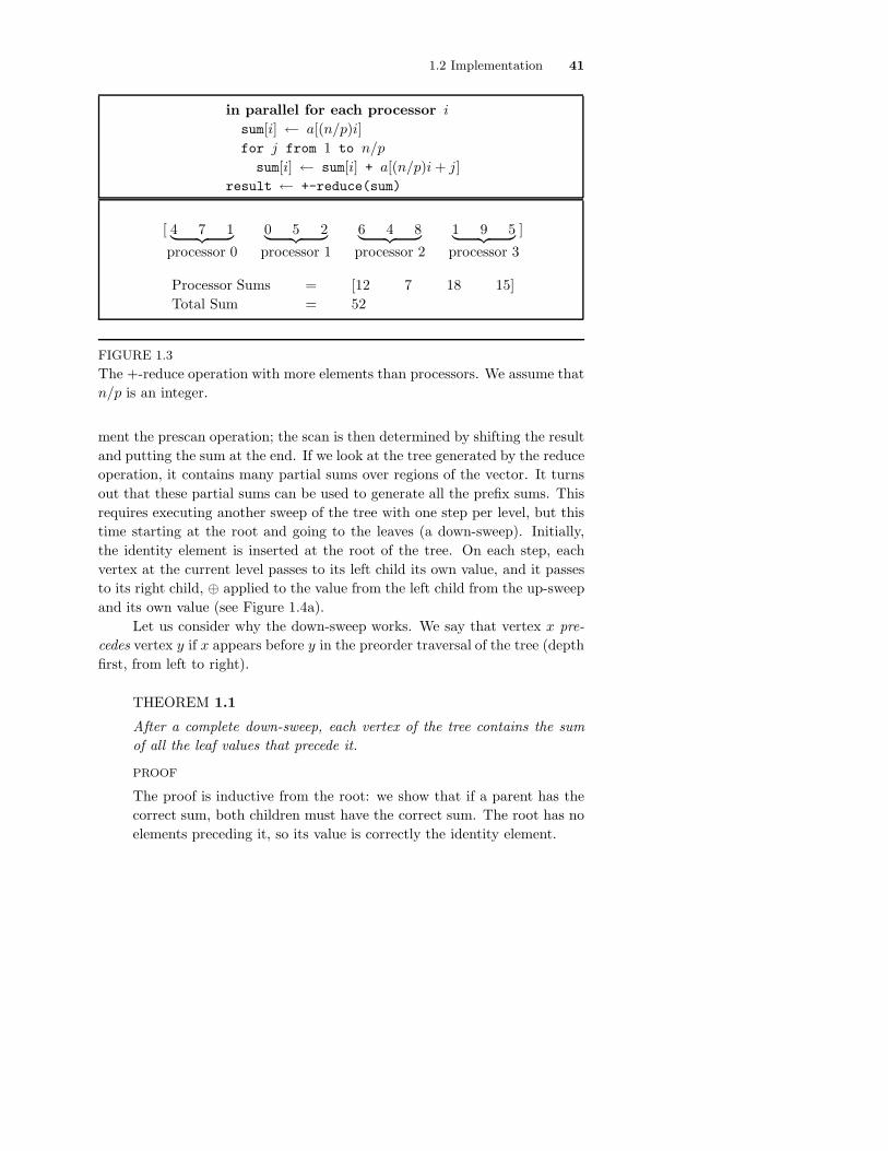
tree technique can then be used to reduce the processor sums (see Figure 1.3).
The time taken to generate the processor sums is ⌈n/p⌉, so the total time
required on an EREW PRAM is:
TR(n, p) = ⌈n/p⌉+ ⌈lg p⌉ = O(n/p + lg p). (1.1)
When n/p ≥ lg p the complexity is O(n/p). This time is an optimal speedup
over the sequential algorithm given in Figure 1.1.
We now return to the scan operation. We actually show how to imple-
1.2 Implementation 41
in parallel for each processor i
sum[i] ← a[(n/p)i]
for j from 1 to n/p
sum[i] ← sum[i] + a[(n/p)i + j]
result ← +-reduce(sum)
[ 4 7 1︸ ︷︷ ︸
processor 0
0 5 2︸ ︷︷ ︸
processor 1
6 4 8︸ ︷︷ ︸
processor 2
1 9 5︸ ︷︷ ︸
processor 3
]
Processor Sums = [12 7 18 15]
Total Sum = 52
FIGURE 1.3
The +-reduce operation with more elements than processors. We assume that
n/p is an integer.
ment the prescan operation; the scan is then determined by shifting the result
and putting the sum at the end. If we look at the tree generated by the reduce
operation, it contains many partial sums over regions of the vector. It turns
out that these partial sums can be used to generate all the prefix sums. This
requires executing another sweep of the tree with one step per level, but this
time starting at the root and going to the leaves (a down-sweep). Initially,
the identity element is inserted at the root of the tree. On each step, each
vertex at the current level passes to its left child its own value, and it passes
to its right child, ⊕ applied to the value from the left child from the up-sweep
and its own value (see Figure 1.4a).
Let us consider why the down-sweep works. We say that vertex x pre-
cedes vertex y if x appears before y in the preorder traversal of the tree (depth
first, from left to right).
THEOREM 1.1
After a complete down-sweep, each vertex of the tree contains the sum
of all the leaf values that precede it.
PROOF
The proof is inductive from the root: we show that if a parent has the
correct sum, both children must have the correct sum. The root has no
elements preceding it, so its value is correctly the identity element.

42 Chapter 1. Prefix Sums and Their Applications
(a) Executing a +-prescan on a tree.
procedure down-sweep(A)
a[n− 1]← 0 % Set the identity
for d from (lg n)− 1 downto 0
in parallel for i from 0 to n− 1 by 2d+1
t← a[i + 2d − 1] % Save in temporary
a[i + 2d − 1]← a[i + 2d+1 − 1] % Set left child
a[i + 2d+1 − 1]← t + a[i + 2d+1 − 1] % Set right child
Step Vector in Memory
0 [ 3 1 7 0 4 1 6 3 ]
up 1 [ 3 4 7 7 4 5 6 9 ]
2 [ 3 4 7 11 4 5 6 14 ]
3 [ 3 4 7 11 4 5 6 25 ]
clear 4 [ 3 4 7 11 4 5 6 0 ]
down 5 [ 3 4 7 0 4 5 6 11 ]
6 [ 3 0 7 4 4 11 6 16 ]
7 [ 0 3 4 11 11 15 16 22 ]
(b) Executing a +-prescan on a PRAM.
FIGURE 1.4
A parallel prescan on a tree using integer addition as the associative operator
⊕, and 0 as the identity.

1.2 Implementation 43
FIGURE 1.5
Illustration for Theorem 1.1.
Consider Figure 1.5. The left child of any vertex has exactly the same
leaves preceding it as the vertex itself (the leaves in region A in the
figure). This is because the preorder traversal always visits the left child
of a vertex immediately after the vertex. By the induction hypothesis,
the parent has the correct sum, so it need only copy this sum to the left
child.
The right child of any vertex has two sets of leaves preceding it, the leaves
preceding the parent (region A), and the leaves at or below the left child
(region B). Therefore, by adding the parent’s down-sweep value, which is
correct by the induction hypothesis, and the left-child’s up-sweep value,
the right-child will contain the sum of all the leaves preceding it.
Since the leaf values that precede any leaf are the values to the left of
it in the scan order, the values at the leaves are the results of a left-to-right
prescan. To implement the prescan on an EREW PRAM, the partial sums
at each vertex must be kept during the up-sweep so they can be used during
the down-sweep. We must therefore be careful not to overwrite them. In fact,
this was the motivation for putting the sums on the right during the reduce
in Figure 1.2b. Figure 1.4b shows the PRAM code for the down-sweep. Each
step can execute in parallel, so the running time is 2 ⌈lg n⌉.
If we assume a fixed number of processors p, with n > p, we can use
a similar method to that in the reduce operation to generate an optimal

44 Chapter 1. Prefix Sums and Their Applications
[ 4 7 1︸ ︷︷ ︸
processor 0
0 5 2︸ ︷︷ ︸
processor 1
6 4 8︸ ︷︷ ︸
processor 2
1 9 5︸ ︷︷ ︸
processor 3
]
Sum = [12 7 18 15]
+-prescan = [0 12 19 37]
[0 4 11︸ ︷︷ ︸
processor 0
12 12 17︸ ︷︷ ︸
processor 1
19 25 29︸ ︷︷ ︸
processor 2
37 38 47︸ ︷︷ ︸
processor 3
]
FIGURE 1.6
A +-prescan with more elements than processors.
algorithm. Each processor first sums an n/p section of the vector to generate
a processor sum, the tree technique is then used to prescan the processor
sums. The results of the prescan of the processor sums are used as an offset
for each processor to prescan within its n/p section (see Figure 1.6). The time
complexity of the algorithm is:
TS(n, p) = 2(⌈n/p⌉+ ⌈lg p⌉) = O(n/p + lg n) (1.2)
which is the same order as the reduce operation and is also an optimal speedup
over the sequential version when n/p ≥ lg p.
This section described how to implement the scan (prescan) operation.
The rest of the chapter discusses its applications.
1.3Line-of-Sight and Radix-Sort
As an example of the use of a scan operation, consider a simple line-of-
sight problem. The line-of-sight problem is: given a terrain map in the form of
a grid of altitudes and an observation point X on the grid, find which points
are visible along a ray originating at the observation point (see Figure 1.7).
A point on a ray is visible if and only if no other point between it and the
observation point has a greater vertical angle. To find if any previous point has
a greater angle, the altitude of each point along the ray is placed in a vector
(the altitude vector). These altitudes are then converted to angles and placed

1.3 Line-of-Sight and Radix-Sort 45
procedure line-of-sight(altitude)
in parallel for each index i
angle[i] ← arctan(scale × (altitude[i] - altitude[0])/ i)
max-previous-angle ← max-prescan(angle)
in parallel for each index i
if (angle[i] > max-previous-angle[i])
result[i] ← "visible"
else
result[i] ← not "visible"
FIGURE 1.7
The line-of-sight algorithm for a single ray. The X marks the observation
point. The visible points are shaded. A point on the ray is visible if no
previous point has a greater angle.
in the angle vector (see Figure 1.7). A prescan using the operator maximum
(max-prescan) is then executed on the angle vector, which returns to each point
the maximum previous angle. To test for visibility each point only needs to
compare its angle to the result of the max-prescan. This can be generalized to
finding all visible points on the grid. For n points on a ray, the complexity of
the algorithm is the complexity of the scan, TS(n, p) = O(n/p + lg n) on an
EREW PRAM.
We now consider another example, a radix sort algorithm. The algorithm
loops over the bits of the keys, starting at the lowest bit, executing a split

46 Chapter 1. Prefix Sums and Their Applications
procedure split-radix-sort(A, number-of-bits)
for i from 0 to (number-of-bits − 1)
A ← split(A, A〈i〉)
A = [5 7 3 1 4 2 7 2]
A〈0〉 = [1 1 1 1 0 0 1 0]
A ← split(A, A〈0〉) = [4 2 2 5 7 3 1 7]
A〈1〉 = [0 1 1 0 1 1 0 1]
A ← split(A, A〈1〉) = [4 5 1 2 2 7 3 7]
A〈2〉 = [1 1 0 0 0 1 0 1]
A ← split(A, A〈2〉) = [1 2 2 3 4 5 7 7]
FIGURE 1.8
An example of the split radix sort on a vector containing three bit values. The
A〈n〉 notation signifies extracting the nth bit of each element of the vector A.
The split operation packs elements with a 0 flag to the bottom and with a 1
flag to the top.
operation on each iteration (assume all keys have the same number of bits).
The split operation packs the keys with a 0 in the corresponding bit to the
bottom of a vector, and packs the keys with a 1 in the bit to the top of
the same vector. It maintains the order within both groups. The sort works
because each split operation sorts the keys with respect to the current bit
(0 down, 1 up) and maintains the sorted order of all the lower bits since we
iterate from the bottom bit up. Figure 1.8 shows an example of the sort.
We now consider how the split operation can be implemented using a
scan. The basic idea is to determine a new index for each element and then
permute the elements to these new indices using an exclusive write. To de-
termine the new indices for elements with a 0 in the bit, we invert the flags
and execute a prescan with integer addition. To determine the new indices of
elements with a 1 in the bit, we execute a +-scan in reverse order (starting at
the top of the vector) and subtract the results from the length of the vector
n. Figure 1.9 shows an example of the split operation along with code to
implement it.
Since the split operation just requires two scan operations, a few steps
of exclusive memory accesses, and a few parallel arithmetic operations, it has
the same asymptotic complexity as the scan: O(n/p + lg p) on an EREW

1.4 Recurrence Equations 47
procedure split(A, Flags)
I-down ← +-prescan(not(Flags))
I-up ← n - +-scan(reverse-order(Flags))
in parallel for each index i
if (Flags[i])
Index[i] ← I-up[i]
else
Index[i] ← I-down[i]
result ← permute(A, Index)
A = [ 5 7 3 1 4 2 7 2 ]
Flags = [ 1 1 1 1 0 0 1 0 ]
I-down = [ 0 0 0 0 0 1 2 2 ]
I-up = [ 3 4 5 6 6 6 7 7 ]
Index = [ 3 4 5 6 0 1 7 2 ]
permute(A, Index) = [ 4 2 2 5 7 3 1 7 ]
FIGURE 1.9
The split operation packs the elements with a 0 in the corresponding flag
position to the bottom of a vector, and packs the elements with a 1 to the
top of the same vector. The permute writes each element of A to the index
specified by the corresponding position in Index.
PRAM.2 If we assume that n keys are each O(lg n) bits long, then the overall
algorithm runs in time:
O((n
p+ lg p) lg n) = O(
n
plg n + lg n lg p).
1.4Recurrence Equations
This section shows how various recurrence equations can be solved using
the scan operation. A recurrence is a set of equations of the form
xi = fi(xi−1, xi−2, · · · , xi−m), m ≤ i < n (1.3)
2On an CREW PRAM we can use the scan described in Chapter 4 to get a time of O(n/p+
lg p/ lg lg p).

48 Chapter 1. Prefix Sums and Their Applications
along with a set of initial values x0, · · · , xm−1.
The scan operation is the special case of a recurrence of the form
xi =
{a0 i = 0
xi−1 ⊕ ai 0 < i < n,(1.4)
where ⊕ is any binary associative operator. This section shows how to reduce
a more general class of recurrences to equation (1.4), and therefore how to
use the scan algorithm discussed in Section 1.2 to solve these recurrences in
parallel.
1.4.1 First-Order Recurrences
We initially consider first-order recurrences of the following form
xi =
{b0 i = 0
(xi−1 ⊗ ai)⊕ bi 0 < i < n,(1.5)
where the ai’s and bi’s are sets of n arbitrary constants (not necessarily scalars)
and ⊕ and ⊗ are arbitrary binary operators that satisfy three restrictions:
1. ⊕ is associative (i.e. (a⊕ b)⊕ c = a⊕ (b⊕ c)).
2. ⊗ is semiassociative (i.e. there exists a binary associative operator
⊙ such that (a⊗ b)⊗ c = a⊗ (b ⊙ c)).
3. ⊗ distributes over ⊕ (i.e. a⊗ (b⊕ c) = (a⊗ b)⊕ (a⊗ c)).
The operator ⊙ is called the companion operator of ⊗. If ⊗ is fully associative,
then ⊙ and ⊗ are equivalent.
We now show how (1.5) can be reduced to (1.4). Consider the set of
pairs
ci = [ai, bi] (1.6)
and define a new binary operator • as follows:
ci • cj ≡ [ci,a ⊙ cj,a, (ci,b ⊗ cj,a)⊕ cj,b] (1.7)
where ci,a and ci,b are the first and second elements of ci, respectively.
Given the conditions on the operators ⊕ and ⊗, the operator • is asso-
ciative as we show below:
(ci • cj) • ck
= [ci,a ⊙ cj,a, (ci,b ⊗ cj,a)⊕ cj,b] • ck
= [(ci,a ⊙ cj,a)⊙ ck,a, (((ci,b ⊗ cj,a)⊕ cj,b)⊗ ck,a)⊕ ck,b]

1.4 Recurrence Equations 49
= [ci,a ⊙ (cj,a ⊙ ck,a), ((ci,b ⊗ cj,a)⊗ ck,a)⊕ ((cj,b ⊗ ck,a)⊕ ck,b)]
= [ci,a ⊙ (cj,a ⊙ ck,a), (ci,b ⊗ (cj,a ⊙ ck,a))⊕ ((cj,b ⊗ ck,a)⊕ ck,b)]
= ci • [cj,a ⊙ ck,a, (cj,b ⊗ ck,a)⊕ ck,b]
= ci • (cj • ck)
We now define the ordered set si = [yi, xi], where the yi obey the recur-
rence
yi =
{a0 i = 0
yi−1 ⊙ ai 0 < i < n,(1.8)
and the xi are from (1.5). Using (1.5), (1.6) and (1.8) we obtain:
s0 = [y0, x0]
= [a0, b0]
= c0
si = [yi, xi] 0 < i < n
= [yi−1 ⊙ ai, (xi−1 ⊗ ai)⊕ bi]
= [yi−1 ⊙ ci,a, (xi−1 ⊗ ci,a)⊕ ci,b]
= [yi−1, xi−1] • ci
= si−1 • ci.
Since • is associative, we have reduced (1.5) to (1.4). The results xi are just
the second values of si (the si,b). This allows us to use the scan algorithm of
Section 1.2 with operator • to solve any recurrence of the form (1.5) on an
EREW PRAM in time:
(T⊙ + T⊗ + T⊕)TS(n, p) = 2(T⊙ + T⊗ + T⊕)(n/p + lg p) (1.9)
where T⊙, T⊗ and T⊕ are the times taken by ⊙, ⊗ and ⊕ (• makes one call to
each). If all that is needed is the final value xn−1, then we can use a reduce
instead of scan with the operator •, and the running time is:
(T⊙ + T⊗ + T⊕)TR(n, p) = (T⊙ + T⊗ + T⊕)(n/p + lg p) (1.10)
which is asymptotically a factor of 2 faster than (1.9).
Applications of first-order linear recurrences include the simulation of
various time-varying linear systems, the backsubstitution phase of tridiagonal
linear-systems solvers, and the evaluation of polynomials.

50 Chapter 1. Prefix Sums and Their Applications
1.4.2 Higher Order Recurrences
We now consider the more general order m recurrences of the form:
xi =
{
bi 0 ≤ i < m
(xi−1 ⊗ ai,1)⊕ · · · ⊕ (xi−m ⊗ ai,m)⊕ bi m ≤ i < n(1.11)
where ⊕ and ⊗ are binary operators with the same three restrictions as
in (1.5): ⊕ is associative, ⊗ is semiassociative, and ⊗ distributes over ⊕.
To convert this equation into the form (1.5), we define the following
vector of variables:
si = [ xi · · · xi−m+1 ]. (1.12)
Using (1.11) we can write (1.12) as:
si = [ xi−1 · · · xi−m ]⊗(v)
ai,1 1 0 · · · 0... 0 1
......
.... . . 0
... 0 · · · 0 1
ai,m 0 · · · 0 0
⊕(v) [ bi 0 · · · 0 ]
= (si−1 ⊗(v) Ai)⊕(v) Bi (1.13)
where ⊗(v) is vector-matrix multiply and ⊕(v) is vector addition. If we use
matrix-matrix multiply as the companion operator of ⊗(v), then (1.13) is in
the form (1.5). The time taken for solving equations of the form (1.11) on an
EREW PRAM is therefore:
(Tm⊗m(m)+Tv⊗m(m)+Tv⊕v(m))TS(n, p) = O((n/p+lg p)Tm⊗m(m)) (1.14)
where Tm⊗m(m) is the time taken by an m⊗m matrix multiply. The sequen-
tial complexity for solving the equations is O(nm), so the parallel complexity
is optimal in n when n/p ≥ lg p, but is not optimal in m—the parallel algo-
rithm performs a factor of O(TM⊗M (m)/m) more work than the sequential
algorithm.
Applications of the recurrence (1.11) include solving recurrences of the
form xi = ai + bi/xi−1 (see problem 10), and generating the first n Fibonacci
numbers x0 = x1 = 1, xi = xi−1 + xi−2 (see problem 11).

1.5 Segmented Scans 51
a = [5 1 3 4 3 9 2 6]
f = [1 0 1 0 0 0 1 0]
segmented +-scan = [5 6 3 7 10 19 2 8]
segmented max-scan = [5 5 3 4 4 9 2 6]
FIGURE 1.10
The segmented scan operations restart at the beginning of each segment. The
vector f contains flags that mark the beginning of the segments.
1.5Segmented Scans
This section shows how the vector operated on by a scan can be broken into
segments with flags so that the scan starts again at each segment boundary
(see Figure 1.10). Each of these scans takes two vectors of values: a data vector
and a flag vector. The segmented scan operations present a convenient way
to execute a scan independently over many sets of values. The next section
shows how the segmented scans can be used to execute a parallel quicksort,
by keeping each recursive call in a separate segment, and using a segmented
+-scan to execute a split within each segment.
The segmented scans satisfy the recurrence:
xi =
a0 i = 0{
ai fi = 1
(xi−1 ⊕ ai) fi = 00 < i < n
(1.15)
where ⊕ is the original associative scan operator. If ⊕ has an identity I⊕,
then (1.15) can be written as:
xi =
{a0 i = 0
(xi−1 ×s fi)⊕ ai 0 < i < n(1.16)
where ×s is defined as:
x×s f =
{I⊕ f = 1
x f = 0.(1.17)
This is in the form (1.5) and ×s is semiassociative with logical or as the
companion operator (see Problem 9). Since we have reduced (1.15) to the

52 Chapter 1. Prefix Sums and Their Applications
form (1.5), we can use the technique described in Section 1 to execute the
segmented scans in time
(Tor + T×s+ T⊕)TS(n, p) . (1.18)
This time complexity is only a small constant factor greater than the
unsegmented version since or and ×s are trivial operators.
1.5.1 Example: Quicksort
To illustrate the use of segmented scans, we consider a parallel version
of quicksort. Similar to the standard sequential version, the parallel version
picks one of the keys as a pivot value, splits the keys into three sets—keys
lesser, equal and greater than the pivot—and recurses on each set.3 The
parallel algorithm has an expected time complexity of O(TS(n, p) lg n) =
O(np
lg n + lg2 n).
The basic intuition of the parallel version is to keep each subset in its
own segment, and to pick pivot values and split the keys independently within
each segment. Figure 1.11 shows pseudocode for the parallel quicksort and
gives an example. The steps of the sort are outlined as follows:
1. Check if the keys are sorted and exit the routine if they are.
Each processor checks to see if the previous processor has a lesser
or equal value. We execute a reduce with logical and to check if all
the elements are in order.
2. Within each segment, pick a pivot and distribute it to the other
elements.
If we pick the first element as a pivot, we can use a segmented scan
with the binary operator copy, which returns the first of its two
arguments:
a← copy(a, b) .
This has the effect of copying the first element of each segment
across the segment. The algorithm could also pick a random ele-
ment within each segment (see Problem 15).
3. Within each segment, compare each element with the pivot and
split based on the result of the comparison.
For the split, we can use a version of the split operation described in
Section 1.3 which splits into three sets instead of two, and which is
3We do not need to recursively sort the keys equal to the pivot, but the algorithm as
described below does.

1.5 Segmented Scans 53
procedure quicksort(keys)
seg-flags[0] ← 1
while not-sorted(keys)
pivots ← seg-copy(keys, seg-flags)
f ← pivots <=> keys
keys ← seg-split(keys, f, seg-flags)
seg-flags ← new-seg-flags(keys, pivots, seg-flags)
Key = [6.4 9.2 3.4 1.6 8.7 4.1 9.2 3.4]
Seg-Flags = [1 0 0 0 0 0 0 0]
Pivots = [6.4 6.4 6.4 6.4 6.4 6.4 6.4 6.4]
F = [= > < < > < > <]
Key ← split(Key, F) = [3.4 1.6 4.1 3.4 6.4 9.2 8.7 9.2]
Seg-Flags = [1 0 0 0 1 1 0 0]
Pivots = [3.4 3.4 3.4 3.4 6.4 9.2 9.2 9.2]
F = [= < > = = = < =]
Key ← split(Key, F) = [1.6 3.4 3.4 4.1 6.4 8.7 9.2 9.2]
Seg-Flags = [1 1 0 1 1 1 1 0]
FIGURE 1.11
An example of parallel quicksort. On each step, within each segment, we dis-
tribute the pivot, test whether each element is equal-to, less-than or greater-
than the pivot, split into three groups, and generate a new set of segment
flags. The operation <=> returns one of three values depending on whether
the first argument is less than, equal to or greater than the second.
segmented. To implement such a segmented split, we can use a seg-
mented version of the +-scan operation to generate indices relative
to the beginning of each segment, and we can use a segmented copy-
scan to copy the offset of the beginning of each segment across the
segment. We then add the offset to the segment indices to generate
the location to which we permute each element.
4. Within each segment, insert additional segment flags to separate
the split values.
Knowing the pivot value, each element can determine if it is at the
beginning of the segment by looking at the previous element.
5. Return to step 1.

54 Chapter 1. Prefix Sums and Their Applications
Each iteration of this sort requires a constant number of calls to the scans
and to the primitives of the PRAM. If we select pivots randomly within each
segment, quicksort is expected to complete in O(lg n) iterations, and therefore
has an expected running time of O(lg n · TS(n, p)).
The technique of recursively breaking segments into subsegments and
operating independently within each segment can be used for many other
divide-and-conquer algorithms, such as mergesort.
1.6Allocating Processors
Consider the following problem: given a set of processors, each contain-
ing an integer, allocate that integer number of new processors to each initial
processor. Such allocation is necessary in the parallel line-drawing routine
described in Section 1. In this line-drawing routine, each processor calcu-
lates the number of pixels in the line and dynamically allocates a processor
for each pixel. Allocating new elements is also useful for the branching part
of many branch-and-bound algorithms. Consider, for example, a brute force
chess-playing algorithm that executes a fixed-depth search of possible moves
to determine the best next move. We can test or search the moves in parallel
by placing each possible move in a separate processor. Since the algorithm
dynamically decides how many next moves to generate (depending on the
position), we need to dynamically allocate new processing elements.
More formally, given a length l vector A with integer elements ai, allo-
cation is the task of creating a new vector B of length
L =
l−1∑
i=0
ai (1.19)
with ai elements of B assigned to each position i of A. By assigned to, we
mean that there must be some method for distributing a value at position i of
a vector to the ai elements which are assigned to that position. Since there is
a one-to-one correspondence between elements of a vector and processors, the
original vector requires l processors and the new vector requires L processors.
Typically, an algorithm does not operate on the two vectors at the same time,
so that we can use the same processors for both.
Allocation can be implemented by assigning a contiguous segment of
elements to each position i of A. To allocate segments we execute a +-prescan

1.6 Allocating Processors 55
V = [v1 v2 v3]
A = [4 1 3]
Hpointers ← +-prescan(A) = [0 4 5]
��
��
��
�� ? ?
Segment-flag = [1 0 0 0 1 1 0 0]
distribute(V, Hpointers) = [v1 v1 v1 v1 v2 v3 v3 v3]
index(Hpointers) = [0 1 2 3 0 0 1 2]
FIGURE 1.12
An example of processor allocation. The vector A specifies how many new
elements each position needs. We can allocate a segment to each position by
applying a +-prescan to A and using the result as pointers to the beginning
of each segment. We can then distribute the values of V to the new elements
with a permute to the beginning of the segment and a segmented copy-scan
across the segment.
on the vector A that returns a pointer to the start of each segment (see Fig-
ure 1.12). We can then generate the appropriate segment flags by writing a
flag to the index specified by the pointer. To distribute values from each posi-
tion i to its segment, we write the values to the beginning of the segments and
use a segmented copy-scan operation to copy the values across the segment.
Allocation and distribution each require one call to a scan and therefore have
complexity TS(l, p) and TS(L, p) respectively.
Once a segment has been allocated for each initial element, it is often
necessary to generate indices within each segment. We call this the index
operation, and it can be implemented with a segmented +-prescan.
1.6.1 Example: Line Drawing
As an example of how allocation is used, consider line drawing. The
line-drawing problem is: given a set of pairs of points
〈(x0, y0) : (x0, y0)〉, . . . , 〈(xn−1, yn−1) : (xn−1, yn−1)〉 ,
generate all the locations of pixels that lie between on of the pairs of points.
Figure 1.13 illustrates an example. The routine we discuss returns a vector of

56 Chapter 1. Prefix Sums and Their Applications
procedure line-draw(x, y)
in parallel for each line i
% determine the length of the line
length[i] ← max(|p2[i].x − p1[i].x|, |p2[i].y − p1[i].y|)
% determine the x and y increments
∆[i].x ← (p2[i].x − p1[i].x) / length[i]
∆[i].y ← (p2[i].y − p1[i].y) / length[i]
% distribute values and generate index
p′1 ← distribute(p1, lengths)
∆′ ← distribute(∆, lengths)
index ← index(lengths)
in parallel for each pixel j
% determine the final position
result[j].x ← p′1[j].x + round(index[j] × ∆′[j].x)
result[j].y ← p′1[j].y + round(index[j] × ∆′[j].y)
FIGURE 1.13
The pixels generated by a line drawing routine. In this example the endpoints
are 〈(11, 2) : (23, 14)〉, 〈(2, 13) : (13, 8)〉, and 〈(16, 4) : (31, 4)〉. The algorithm
allocates 12, 11 and 16 pixels respectively for the three lines.

1.7 Exercises 57
(x, y) pairs that specify the position of each pixel along every line. If a pixel
appears in more than one line, it will appear more than once in the vector.
The routine generates the same set of pixels as generated by the simple digital
differential analyzer sequential technique.
The basic idea of the routine is for each line to allocate a processor
for each pixel in the line, and then for each allocated pixel to determine, in
parallel, its final position in the grid. Figure 1.13 shows the code. To allocate
a processor for each pixel, each line must first determine the number of pixels
in the line. This number can be calculated by taking the maximum of the x
and y differences of the line’s endpoints. Each line now allocates a segment of
processors for its pixels, and distributes one endpoint along with the per-pixel
x and y increments across the segment. We now have one processor for each
pixel and one segment for each line. We can view the position of a processor
in its segment as the position of a pixel in its line. Based on the endpoint the
slope and the position in the line (determined with a index operation), each
pixel can determine its final (x, y) location in the grid.
This routine has the same complexity as a scan TS(m, p), where m is
the total number of pixels. To actually place the points on a grid, rather than
just generating their position, we would need to permute a flag to a position
based on the location of the point. In general, this will require the simplest
form of concurrent-write (one of the values gets written), since a pixel might
appear in more than one line.
1.7Exercises
1.1 Modify the algorithm in Figure 1.4 to execute a scan instead of a prescan.
1.2 Use the scan operation to compare two strings of length n in O(n/p + lg p)
time on an EREW PRAM.
1.3 Given two vectors of bits that represent nonnegative integers, show how a
prescan can be used to add the two numbers (return a vector of bits that
represents the sum of the two numbers).
1.4 Trace the steps of the split-radix sort on the vector
[2 11 4 5 9 6 15 3].
1.5 Show that subtraction is semiassociative and find its companion operator.
1.6 Write a recurrence equation of the form (1.5) that evaluates a polynomial
y = b1xn−1 + b2x
n−2 + · · · + bn−1x + bn

58 Chapter 1. Prefix Sums and Their Applications
for a given x.
1.7 Show that if ⊗ has an inverse, the recurrence of the form (1.5) can be solved
with some local operations (not involving communication among processors)
and two scan operations (using ⊗ and ⊕ as the operators).
1.8 Prove that vector-matrix multiply is semiassociative.
1.9 Prove that the operator ×s defined in (1.17) is semiassociative.
1.10 Show how the recurrence x(i) = a(i) + b(i)/x(i − 1), where + is numeric
addition and / is division, can be converted into the form (1.11) with two
terms (m = 2).
1.11 Use a scan to generate the first n Fibonacci numbers.
1.12 Show how to solve a tridiagonal linear-system using the recurrences in Sec-
tion 1.4. Is the algorithm asymptotically optimal?
1.13 In the language Common Lisp, the % character means that what follows the
character up to the end of the line is a comment. Use the scan operation to
mark all the comment characters (everything between a % and an end-of-
line).
1.14 Trace the steps of the parallel quicksort on the vector
[27 11 51 5 49 36 15 23].
1.15 Describe how quicksort is changed so that it selects a random element within
each segment for a pivot.
1.16 Design an algorithm that given the radius and number of sides on a regular
polygon, determines all the pixels that outline the polygon.
Notes and References
The all-prefix-sums operation has been around for centuries as the recur-
rence xi = ai +xi−1. A parallel circuit to execute the scan operation was first
suggested by Ofman (1963) for the addition of binary numbers. A parallel
implementation of scans on a perfect shuffle network was later suggested by
Stone (1971) for polynomial evaluation. The optimal algorithm discussed in
Section 1.2 is a slight variation of algorithms suggested by Kogge and Stone
(1973) and by Stone (1975) in the context of recurrence equations.
Ladner and Fischer (1980) first showed an efficient general-purpose cir-
cuit for implementing the scan operation. Brent and Kung (1980), in the

1.7 Bibliography 59
context of binary addition, first showed an efficient VLSI layout for a scan
circuit. More recent work on implementing scan operations in parallel include
the work of Fich (1983) and of Lakshmivarahan, Yang and Dhall (1987), which
give improvements over the circuit of Ladner and Fischer, and of Lubachevsky
and Greenberg (1987), which demonstrates the implementation of the scan
operation on asynchronous machines. Blelloch (1987) suggested that certain
scan operations be included in the PRAM model as primitives and shows how
this affects the complexity of various algorithms. Work on the linked-list-
based all-prefix-sums operation is considered and referenced in Chapters 2, 3
and 4.
The line-of-sight and radix-sort algorithms are discussed by Blelloch
(1988, 1990). The parallel solution of recurrence problems was first discussed
by Karp, Miller and Winograd (1967), and parallel algorithms to solve them
are given by Kogge and Stone (1973), Stone (1973, 1975) and Chen and Kuck
(1975). Hyafil and Kung (1977) show that the complexity (1.10) is a lower
bound.
Schwartz (1980) and, independently, Mago (1979) first suggested the
segmented versions of the scans. Blelloch (1990) suggested many uses of
these scans including the quicksort algorithm and the line-drawing algorithm
presented in Sections 1 and 1.
I would like to thank Siddhartha Chatterjee, Jonathan Hardwick and
Jay Sipelstein for reading over drafts of this chapter.
Bibliography
Blelloch, G.E., Scans as Primitive Parallel Operations. IEEE Transactions on Com-
puters, C-38(11):1526–1538, November 1989.
Blelloch, G.E., Vector Models for Data-Parallel Computing. MIT Press, Cambridge,
MA, 1990.
Blelloch, G.E., and Little, J.J., Parallel Solutions to Geometric Problems on the Scan
Model of Computation. In Proceedings International Conference on Parallel
Processing, pages Vol 3: 218–222, August 1988.
Brent, R.P., and Kung, H.T., The Chip Complexity of Binary Arithmetic. In Pro-
ceedings ACM Symposium on Theory of Computing, pages 190–200, 1980.
Chen, S., and Kuck, D.J., Time and Parallel Processor Bounds for Linear Recurrence
Systems. IEEE Transactions on Computers, C-24(7), July 1975.
Fich, F.E., New Bounds for Parallel Prefix Circuits. In Proceedings ACM Symposium
on Theory of Computing, pages 100–109, April 1983.

60 Chapter 1. Prefix Sums and Their Applications
Hyafil, L., and Kung, H.T., The Complexity of Parallel Evaluation of Linear Recur-
rences. Journal of the Association for Computing Machinery, 24(3):513–521,
July 1977.
Karp, R.H., Miller, R.E., and Winograd S., The Organization of Computations for
Uniform Recurrence Equations. Journal of the Association for Computing
Machinery, 14:563–590, 1967.
Kogge, P.M., and Stone, H.S., A Parallel Algorithm for the Efficient Solution of a
General Class of Recurrence Equations. IEEE Transactions on Computers,
C-22(8):786–793, August 1973.
Ladner, R.E., and Fischer, M.J., Parallel Prefix Computation. Journal of the Asso-
ciation for Computing Machinery, 27(4):831–838, October 1980.
Lakshmivarahan, S., Yang, C.M., and Dhall, S.K., Optimal Parallel Prefix Circuits
with (size + depth) = 2n−n and ⌈log n⌉ ≤ depth ≤ ⌈2 log n⌉−3. In Proceedings
International Conference on Parallel Processing, pages 58–65, August 1987.
Lubachevsky, B.D., and Greenberg, A.G., Simple, Efficient Asynchronous Parallel
Prefix Algorithms. In Proceedings International Conference on Parallel Pro-
cessing, pages 66–69, August 1987.
Mago, G.A., A network of computers to execute reduction languages. International
Journal of Computer and Information Sciences, 1979.
Ofman, Y., On the Algorithmic Complexity of Discrete Functions. Soviet Physics
Doklady, 7(7):589–591, January 1963.
Schwartz, J.T., Ultracomputers. ACM Transactions on Programming Languages
and Systems, 2(4):484–521, October 1980.
Stone, H.S., Parallel Processsing with the Perfect Shuffle. IEEE Transactions on
Computers, C-20(2):153–161, 1971.
Stone, H.S., An Efficient Parallel Algorithm for the Solution of a Tridiagonal Linear
System of Equations. Journal of the Association for Computing Machinery,
20(1):27–38, January 1973.
Stone, H.S., Parallel Tridiagonal Equation Solvers. ACM Transactions on Mathe-
matical Software, 1(4):289–307, December 1975.