price $ 5.00 sona-trol - waddington electronics inc. · calibration ... sona-trol installed in a...
TRANSCRIPT

Price $ 5.00
SONA-TROLSensing and Control system
Users Manual
PatentedWaddington Electronics Inc
25 Webb St, Cranston, RI 02920-7922P. 1-401-781-3904 F. 1-401-781-1650
WWW.waddingtonelectronics.com
Model # Serial #

JW sonatrol manual.doc 2
Table of ContentsProduct Description ........................................................................................................................................ 3
ST-6 STANDARD FEATURES................................................................................................................. 3ST-6 OPTIONAL FEATURES .................................................................................................................. 3SY-2 SYNCHRONIZER FEATURES ....................................................................................................... 3SY-8 SYNCHRONIZER FEATURES ....................................................................................................... 4OTHER OPTIONS ..................................................................................................................................... 4
Typical Applications........................................................................................................................................ 5Metal Stamping Line ....................................................................................................................................... 5Distance Measurement.................................................................................................................................... 6Diameter Measurement................................................................................................................................... 7Specifications.................................................................................................................................................. 8
OPERATING REQUIREMENTS .............................................................................................................. 8TRANSDUCER RANGE RESOLUTION ACCURACY .......................................................................... 8ENVIRONMENTAL TRANSDUCER ...................................................................................................... 8ANALOG OUTPUT VOLTAGE ............................................................................................................... 8
Installation .................................................................................................................................................... 13UNPACKING........................................................................................................................................... 13Installation Instructions............................................................................................................................. 13Sensor Head Location ............................................................................................................................... 13
Adjustments .................................................................................................................................................. 14Preliminary Adjustments .......................................................................................................................... 14LOOP CONTROL .................................................................................................................................... 14
OPTIONAL GAIN ADJUSTMENTS: ................................................................................................. 14LIMIT BOARD ADJUSTMENTS ....................................................................................................... 14FORCING ZERO OUTPUT WITH THE BOTTOM LIMIT:.............................................................. 14TOP LIMIT OPERATION: .................................................................................................................. 14
Field Adjustments ......................................................................................................................................... 15TIME FILTER P5................................................................................................................................. 15BOTTOM LIMIT P3 ............................................................................................................................ 15TOP LIMIT P4 ..................................................................................................................................... 15DISTANCE P1 ..................................................................................................................................... 15GAIN P2 ............................................................................................................................................... 16
Tension Adjustments (TC6 Models Only).................................................................................................... 16CALIBRATION ....................................................................................................................................... 16
Level Control Adjustments ........................................................................................................................... 17Diameter Measurement Adjustments (Fixed Core) ...................................................................................... 17Loop Sensing Adjustments ........................................................................................................................... 17
PAY OUT (MACHINE STOPPED)..................................................................................................... 17TAKE UP (MACHINE STOPPED) ..................................................................................................... 17PAY OUT (MACHINE STARTED) .................................................................................................... 17TAKE UP (MACHINE STARTED)..................................................................................................... 18
Theory of Operation...................................................................................................................................... 18Connections .................................................................................................................................................. 19Sensor Head Cable Connections ................................................................................................................... 20Sy2 Master and Slave Options ...................................................................................................................... 21Base Speed Connection................................................................................................................................. 21
Example Sonatrol and 5 HP DC regen Straightener Package ................................................................... 23Diagnostics Diagram for Sona-Trol .............................................................................................................. 24Troubleshooting ............................................................................................................................................ 25

JW sonatrol manual.doc 3
Product DescriptionSONA-TROL, the only PATENTED NON-CONTACT loop control, is NOT limited to loop controlapplications.SONA-TROL installed in a storage tank, can be used to control the level of liquids or solids.SONA-TROL can be used to control unwind and rewind tension.SONA-TROL can be used to detect the presence or absence of objects, such as pallets in automatedwarehouses.SONA-TROL can sense changes in distance, within its detection area, as small as 0.010 inches.SONA-TROL is supplied in many models, each with a variety of standard and optional features, allowingyou to customize your particular NON-CONTACT sensing and control system application.
ST-6 STANDARD FEATURESAdjustable distance (from sensor) zero offsetAdjustable gainOperating Range: 1.5 to 20 feetAdjustable receiver sensitivitySensor head cable length: 10 feetOil-tight JIC controller enclosureElectrically-isolated sensor headAn exclusive circuit, for use in loop control applications where bouncing strips are likely to cause falsemeasurements. This proprietary circuit detects false signals and rejects them, allowing SONA-TROL toprovide proper take-up or pay-out smoothness regardless of strip bounce or sway.Built-in provisions for external control of measurement rate. This is often used in applications whereSONA-TROL operates in conjunction with a programmable controller, an external computer, or one of thesequencers described below.
ST-6 OPTIONAL FEATURESDual sensors for wide sensing areaMultiple limit switch outputs (up to 20 per sensor)Adjustable measurement repetition rateMultiple sensor array sequencer (up to 128 sensors)Digital or analog readout for object distance (from sensor) or heightScaled readouts to measure the volume of liquids or solids contained in storage tanksWide range of voltage outputsCurrent loop output: 0 to 10 MA or 4 to 20 MASensor head cable length: up to 1000 feetHigh resolution sensor head; detection distance range: 2 inches to 20 inches
SY-2 SYNCHRONIZER FEATURESThe SY-2 is a two-channel synchronizer that allows the use of two sensor heads in close proximity to eachother. It does this by connecting the external measurement control input of two SONA-TROL ST-6 circuitboards. The SY-2 controls when transmit will occur, eliminating interference between controls.

JW sonatrol manual.doc 4
SY-8 SYNCHRONIZER FEATURESThe SY-8 is an eight-channel synchronizer that can control the sequence and measurement rate of up to eightSONA-TROL controls. This board also connects to the external rate control input of the ST-6 main circuitboard.
OTHER OPTIONSRMS Output BoardPID Output BoardOutput: 0 to 10 MA or 4 to 20 MA12 Bit Binary Output Isolated 5 to 15 V LogicAnalog Multiplier0 to 78 PSI Output0 to 90 VDC OutputAcoustic HornExtended range sensor head 6 inches to 20 feetSee EZ-Circuit Analog Function Modules catalog for additional options

JW sonatrol manual.doc 5
Typical Applications
Rotary Screen print machine
Metal Stamping Line

JW sonatrol manual.doc 6
Distance Measurement

JW sonatrol manual.doc 7
Diameter Measurement

JW sonatrol manual.doc 8
Specifications
OPERATING REQUIREMENTS
Power Requirements115 VAC +/- 5% at 0.25 Amperes nominal, 60 Hz. (50 Hz. Optional) 220VAC +/- 5% at 0.125 Amperes nominal, 50/60 Hz. Other voltages onrequest.
EnvironmentOperating Temperature 20 to 160 degrees Fahrenheit Storage Temperaturesame as Operating Temperature Humidity 95% (noncondensing)
TRANSDUCER RANGE RESOLUTION ACCURACY
Standard and Environmental1.5 to 20 feet 0.05 in. +/- 0.050
Extended Range6" to 20 feet 0.050 in. +/- 0.005 in
E201/215 High Resolution3 to 24 inches 0.005 in. +/- 0.010 in.
E201/150 High Resolution5 to 48 inches 0.005 in. +/- 0.010 in.
ENVIRONMENTAL TRANSDUCER
The Environmental Transducer is of stainless steelconstruction for operation in severe environments where other materialwould be degraded. Environmental Transducers should be used inapplicationssuch as the food industry, where frequent cleaning is required.
ANALOG OUTPUT VOLTAGE
Analog Output Voltage Gain Range: 25 MV/Inch to 1.25V/Inch. Other gain ranges available.
Note: Output is isolated on systems using standard type sensorheads only, not on high resolution models.
ALL POTENTIOMETERS ARE 15 TURN POTS

JW sonatrol manual.doc 9

JW sonatrol manual.doc 10

JW sonatrol manual.doc 11

JW sonatrol manual.doc 12

JW sonatrol manual.doc 13
Installation
UNPACKINGAfter unpacking the controller and/or motor, inspect the equipment for loose parts, broken or missingcomponents, dents, and any evidence of mishandling. Check the model type, input voltage, and power ratingagainst the order description.CAUTION: IF THERE IS ANY EVIDENCE OF PHYSICAL DAMAGE, DO NOT CONTINUE. DONOT INSTALL DAMAGED EQUIPMENT.
Installation InstructionsMOUNTING LOCATIONAvoid mounting the SONA-TROL main enclosure where it might be subjected to extremes of vibration (abouncing press), temperature or moisture.
POWER CONNECTIONSCAUTION: THE INTERNAL PARTS OF THE MOTOR AND CONTROLLER CAN BE AT LINEPOTENTIAL WHETHER OR NOT THE EQUIPMENT IS FUNCTIONING. BEFORE TOUCHING ANYINTERNAL PARTS, DISCONNECT BOTH INCOMING A.C. POWER CABLES.Before applying power to the SONA-TROL system, verify that the name plate data corresponds to the powersource being connected to the terminal block.
Sensor Head LocationLOOPIn loop control applications, mount the sensor perpendicular to the center of the loop.LEVELFor level control applications, place the sensor facing perpendicular to the surface being measured.DIAMETERIn applications for diameter measurement, diameter to tension control,and diameter to constant speed, mount the sensor at a right angle to theroll of material being sensed. The sensor should be mounted so that animaginary line can be drawn from the sensor to a point on the axis of theroll at 90 degrees to the axis.

JW sonatrol manual.doc 14
AdjustmentsCAUTION: THE INTERNAL PARTS OF THE MOTOR AND CONTROLLER CAN BE AT LINEPOTENTIAL WHETHER OR NOT THE EQUIPMENT IS FUNCTIONING. BEFORE TOUCHING ANYINTERNAL PARTS, DISCONNECT BOTH INCOMING A.C. POWER CABLES.
Preliminary Adjustments(Also see Field Adjustments pg. 5-1)
LOOP CONTROLSet P5 to adjust the Time Filter so that the row of lights, in the lower right corner of the board, beginsto strobe (flash in sequence) when the strip is 2 inches from the floor. Above 2 inches from the floor,only the first light should flash. THIS IS ESPECIALLY IMPORTANT WHEN A NARROWBOUNCING STRIP IS BEING CONTROLLED.
Set P2 minimum full clockwise.Set P1 for zero volts at the desired distance from the sensor.Set P2 for the desired voltage change per inch of distance change. That is the amount of change in Speed,Tension, Volume, and Diameter.
OPTIONAL GAIN ADJUSTMENTS:Fixed gain switches override the automatic gain changes to minimize the effects of interference; air blasts,obstructions in the detection area, etc.
LIMIT BOARD ADJUSTMENTSSONA-TROL limit boards provide contact closure outputs for customer use. The status of the contacts,shown on the terminal block diagram, change when the preset limits are reached and the relays arede-energized. The relay SETPOINTS are adjusted with a potentiometer. When the Bottom Limit board isenergized, the light (LED) on the sensor head turns on.
BOTTOM LIMIT OPERATION:The bottom limit board is located on the left side of the enclosure. The bottom limit can be used to shut off atake-up control if the material being sensed breaks or if the loop is disturbed (for inspection by the operator).The bottom limit board de-energizes as the sensed object falls below its setpoint. THE BOTTOM LIMITSHOULD BE USED ON ALL PUNCH PRESS TAKEUPS OR OTHER SIMILAR APPLICATIONS
FORCING ZERO OUTPUT WITH THE BOTTOM LIMIT:To shut off SONA-TROL with the bottom limit, connect the normally closed bottom limit contact terminals,(14 and 15), to the analog output terminals (7 and 8). When the bottom limit is reached the relay de-energizesand forces the SONA-TROL to zero volts.
TOP LIMIT OPERATION: The top limit can be used to control other equipment used in conjunction with SONA-TROL. The top limitboard de-energizes as the sensed object moves above its setpoint.

JW sonatrol manual.doc 15
Field Adjustments
TIME FILTER P5This potentiometer sets the maximum distance allowed for a round trip echo, before it is discounted by thetime filter as a bad echo. Refer below. Set P5 to adjust the Time Filter so that the row of lights, in the lowerright corner of the board, begin to strobe (flash in sequence) when the strip is 2 inches from the floor. Above 2inches from the floor, only the first light should flash.THIS IS ESPECIALLY IMPORTANT WHEN ANARROW BOUNCING STRIP IS BEING CONTROLLED.
BOTTOM LIMIT P3 The bottom limit is located on the left side of the panel. The relay setpoint is moved further away from thetransducer as the potentiometer is turned counterclockwise.
TOP LIMIT P4- The top limit is located of the right side of the panel. The relay setpoint is moved further away from thetransducer as the potentiometer is turned counterclockwise.
DISTANCE P1- This potentiometer is used to set zero voltage (Zero Speed, Zero Tension, Zero Volume, Zero Diameter, etc.)at the desired distance from the sensor head.

JW sonatrol manual.doc 16
GAIN P2- Adjustment of this potentiometer will set the amount of voltage change per inch of distance change (Speed,Tension, Volume, Diameter, etc.).Max Gain (CCW) = 1.25 V/inch.Min Gain (CW) = 25 mV/inch.
Tension Adjustments (TC6 Models Only)NOTE: In diameter measurement and diameter to tension control, it is important to direct the sensor at thecore of the diameter being sensed. Otherwise false readings will result.Locate center of roll.Set Gain potentiometer (POT) P2 at midpoint.Set Auto/Man switch on cover to Auto.Set tension POT on cover to full on or 100%.Set zero volts out at terminals 7 & 8 with POT P1 Distance Core Diameter.Put Maximum Diameter roll on machine and set output at terminals 7 & 8 to be: 0.1 volts X {(Roll OD)/2 -(Core OD)/2}.Remove the roll and measure the output at terminals 7 & 8, the correct reading is zero volts. Otherwise repeatsteps 2 and 3.Adjust POT P1 until the output reads: 0.1 volts X Core OD/2
CALIBRATIONReplace the maximum diameter roll on the machine and set the tension POT to full or 100%.Set the output at terminals 7 & 8 on the ST-6 board to maximum torque command required for theparticular application; 10 volts max. adjusted with Gain POT P2. The input voltage is measured at

JW sonatrol manual.doc 17
terminals 1 and 2. (For the 4 to 20 MA option: at terminals 29 and 30; 0 Volts out = 4 MA, and 10 Voltsout = 20 MA).Constant tension can now be set with the Tension POT for any value between zero and 100%.Adjustment of POTS P1 and P2 is complete.With Auto/Man switch in manual position use main adjusment POT on cover to set output (Note: Autooutput is disconnected in this mode).
Level Control AdjustmentsMount the sensor so that it faces the bottom of the tank.Set P5 on the ST-6 board until the first light flashes.Set P2 on the ST-6 board at approximately 20% from minimum.For an empty tank, set zero output at terminals 7 and 8 on the ST-6 board.THE TANK MUST BE EMPTY FOR THIS ADJUSTMENT.For a full tank, adjust P2 on the ST-6 board for the desired output at terminals 7 and 8 (with meterattached).
Diameter Measurement Adjustments (Fixed Core)Use the procedures for Tension Control.
Loop Sensing AdjustmentsMount the sensor facing perpendicular to the center of the loop, at least 18 inches above the pass line ortight loop. Then remove the material.Turn on the controller.Adjust P5, on the ST-6 board, counter clockwise until the first LED flashes.SLOWLY adjust P5 clockwise until the lights begin to strobe (flash sequentially).To check P5 adjustment, place an object (or the material to be sensed) 6 inches above the floor. Onlythe first light should flash. Otherwise remove the object and repeat steps 3 and 4.
PAY OUT (MACHINE STOPPED)Set the gain POT P2 for 50% of maximum.Adjust P1 output at terminals 7 and 8, with a full loop (down to the 6 inch limit), so that only the first lightflashes.NOTE: For proper operation, terminals 7& 8 (and the zener diode if present) may have to be reversed.<R>
TAKE UP (MACHINE STOPPED)Set the gain POT P2 for 50% of maximum.Adjust P1 output at terminals 7 and 8 for zero volts at the desired loop size.Start the machineNOTE: For proper operation, terminals 7& 8 (and the zener diode if present) may have to be reversed.
PAY OUT (MACHINE STARTED)If the loop gets too small, increase the gain using P2 (CCW).Adjust P2 until smooth operation is achieved while machine is running.

JW sonatrol manual.doc 18
TAKE UP (MACHINE STARTED)If the loop gets too big, increase the gain using P2 (CCW).Adjust P2 until smooth operation is achieved while machine is running.NOTE: Excessive gain will cause the loop to oscillate (fluctuate between big and small).
Theory of OperationSONA-TROL operates on the basic principles of SONAR (SOund NAvigation and Ranging) andincorporates state of the art digital and analog electronics.The sound transducer, located in the sensor head, is driven by electronics also located in the sensor head.Driven by the sensor head electronics, the transducer emits a one millisecond tone burst (approximately 50KHz). Then for a short time period the sensor waits for the transducer vibrations to subside. After the timedelay the transducer acts as a microphone and waits for the tone burst to be reflected back from the objectbeing sensed (controlled). It is this time interval, between transmit and receive, that forms the basis for allSONA-TROL control functions. In essence SONA-TROL “measures” the distance between the sensor andthe sensed object.The information derived from the time interval is either discarded by the time filter or the analog output isupdated to the latest control conditions.

JW sonatrol manual.doc 19
Connections

JW sonatrol manual.doc 20
Sensor Head Cable Connections
JW sonatrol manual.doc 21
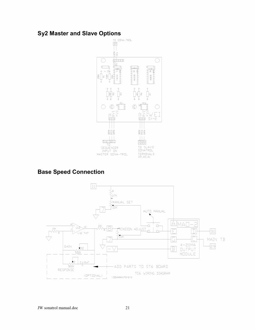
Sy2 Master and Slave Options
Base Speed Connection

JW sonatrol manual.doc 22

JW sonatrol manual.doc 23
Example Sonatrol and 5 HP DC regen Straightener Package

JW sonatrol manual.doc 24
Diagnostics Diagram for Sona-Trol

JW sonatrol manual.doc 25
Troubleshooting
PREVIOUSLY FUNCTIONING INSTALLATIONSPROBLEM CORRECTIVE ACTIONLoss of sensitivity Clean with low pressure air only or replace transducer.Erratic operation Reduce electrical noise of customer equipment. Re-move interference from within thedetection area (including air blasts).
NEW INSTALLATIONSPROBLEM CORRECTIVE ACTIONFalse readings Adjust sensor head locationErratic operation Adjust sensor head locationNOTE: A common problem in new loop control installations is faulty operation caused by positioning thesensor too close to the bottom of the loop. Raise the sensor, while keeping it positioned over the loop, untilproper operation is obtained.
WARRANTY AND REPAIR
If the corrective procedures described in Section 4.1 fail to resolve the problem, and it appears that theSONA-TROL is the source of difficulty, call Waddington Electronics Customer Service at the telephonenumber shown below. Customer Service (401) 781-3904Before calling the customer service number, you should have the following information available: A detaileddescription of the problemDate you received the productModel number and serial number of the productYour shipping and billing address, should the product need to be returned.If your SONA-TROL warranty has expired, you will also need the purchase order number for billingpurposes.
RETURNING PRODUCTShould the product need to be returned for repair, the Waddington Electronics Customer Service person willgive you a Return Authorization (RMA) Number. The RMA number is valid for 30 days.PLEASE NOTE All returns to factory (warranty, non-warranty, and exchanges) require a ReturnMerchandise Authorization (RMA) number.A parcel received without an RMA number noted on the outside of the box WILL BE REFUSED by theReceiving Department at Waddington Electronics and WILL BE RETURNED freight collect.Unless otherwise requested, all Waddington Electronics shipments within the continental U.S. are sent U.P.S.and are insured. All charges are prepaid and billed.
WADDINGTON ELECTRONICS CUSTOMER SERVICE NUMBERPhone: (401) 781-3904 - Fax Number: (401) 781-1650
For warranty provisions, refer to Appendix B at the end of this manual. SONA-TROL products can bereturned for repair (warranty or non-warranty) following the standard or emergency proceduredetailed below.
FACTORY REPAIR
An RMA number, as described above, is required.Product must be returned freight and insurance prepaid. See RMA marking requirements.Product will be returned, repaired or exchanged within 10 working days.The return freight will be paid by the customer.

JW sonatrol manual.doc 26
EMERGENCY REPLACEMENT
An RMA number, as described above is required.Product must be returned immediately, freight and insurance prepaid .A replacement will be shipped air freight prepaid within one (1) business day.Customer will be invoiced for a replacement unit, expedite charges of $100, and return freight. Credit for thefailed unit will be issued upon receipt of the failed unit.