price rooftop unit controller - price web server
TRANSCRIPT

w w w . p r i c e - h v a c . c o m
PRTUPRICE ROOFTOP UNIT CONTROLLER
Date: 06 /11Reference # : F2-40
INSTALLATION MANUAL

Page 2 of 31
Introduction ................................................................................................. 3 PRTU default Sequence of Operations ....................................................... 4 Included in Package ................................................................................... 6 Overview of the PRTU ................................................................................ 7 Installation and Mounting ............................................................................ 8 Wiring ....................................................................................................... 10 Zone Polling via BACnet MS/TP network .................................................. 12 LCD thermostat – Initial start up ................................................................ 14 Service Menu and TIME/MODE Buttons ................................................... 14 Service Menu ............................................................................................ 15
Short circuit or incorrect wiring may permanently damage the controls or other
equipment. Ensure proper wiring practices. The PRTU is to be used only as an
operating controller. If a control failure could lead to personal and/or property
damage, the installer must add safety/interlock devices to protect against these
events.
Manual Version – V1.0
0616L
www.price-hvac.com/literature
www.priceelectronics.ca

Page 3 of 31
INTRODUCTION
The Price Rooftop Unit Controller (PRTU) is intended to provide intelligent controller of packaged single
and multi-stage rooftop equipment typically in the 5 – 50 ton range. A variety of configurable binary and
analog outputs allow control of virtually all rooftop units. All models feature 10 protected binary outputs
and 4 protected analog outputs. Indicator LEDs show status of each output in green, red or yellow.
The PRTU comes with a backlit LCD thermostat with password protected menus to fully configure and
setup the unit in the field. Accurate temperature control is accomplished with a proportional integral (PI)
algorithm.
The PRTU can function in stand-alone mode (not networked to any zone controllers) or can be networked
to poll Price Controllers (Price Intelligent Controller – PIC, Prodigy Smart Diffuser) via BACnet MS/TP.
PRTU CONTROLLER FEATURES
• On board Real Time Clock and Calendar for scheduling
• Super Capacitor backup keeps time clock running during power failures
• Discharge Air Temperature (D.A.T.) monitoring – prevents excessive temperature swings that can
trip safeties and waste energy
• Return Air Temperature (R.A.T.) monitoring – monitors return air to RTU and prevents freeze up
of coil or overheating that can trip safeties and waste energy
• 10 binary outputs rated at 0.5 amps each, protected with thermal fuse (RED LED on trip),
automatic recovery when fault is corrected
• Switch for selecting binary output type (24 VAC – HOT, COMMON or external)
• 4 analog outputs (0-10 VDC), fully configurable for FAN, heating, cooling and spare
• Multi-level surge protection with user replaceable MINI type fuse
• Pluggable terminal blocks
• BACnet MS/TP Client/Server stack for polling zones for data
• LED’s for BACnet wiring fault, BACnet network fault, and MS/TP termination
PRTU THERMOSTAT FEATURES
• Backlit 14x2 LCD thermostat with true character display
• Motion Sensor on thermostat allows automatic occupancy mode
• Password protected menu
• Easy to use MENU system for fast and simple setup of system
• Local precision thermistor
• Service port for use with Price LINKER software
• Included RJ45 plenum rated cable for fast, error free hookup
• Wizard – walk through setup of PRTU when first powered up

Page 4 of 31
PRTU DEFAULT SEQUENCE OF OPERATIONS
The PRTU can function in stand-alone mode (not networked to any zone controllers) or can be networked
to poll Price Controllers (Price Intelligent Controller – PIC, Prodigy Smart Diffuser) via BACnet MS/TP. If
set to networked mode and the PRTU cannot poll the zones properly due to, bad address, bad wiring, etc
the unit will show BACnet Health of 0% and will default to stand alone mode. In stand-alone mode the
PRTU uses its local thermostat and set points to control the RTU.
STAND ALONE MODE
In this mode the PRTU will control the packaged RTU based on the local temperature conditions as
measured at the PRTU thermostat.
On an increase in space temperature into the cooling proportional band the PRTU will progressively
engage stages of cooling (up to 4) in the packaged rooftop unit. On an increase of space temperature
greater than the cooling proportional band, all active cooling stages will be energized. As the space
temperature approaches the cooling set point, the PRTU will de-energize active cooling stages.
On an decrease in space temperature into the heating proportional band the PRTU will progressively
engage stages of heating (up to 4) in the packaged rooftop unit. On an decrease of space temperature
greater than the heating proportional band, all active heating stages will be energized. As the space
temperature approaches the heating set point, the PRTU will de-energize active heating stages.
Separate heating and cooling set points, along with adjustable changeover timers prevent system cycling
between heating and cooling modes. Heating and cooling set points are separated by a default value of
4F (2C).
Using the included two 10k thermistor probes (Type J), the PRTU will monitor the air temperature as it is
discharged (D.A.T. - measured on AI1) and returned (R.A.T – measured on AI2) to the rooftop unit.
If either of the air temperatures exceed the adjustable limits, active heating and cooling stages are de-
energized to prevent low or high temperature lockouts in the packaged rooftop unit.
Adjustable minimum on/off times prevent short cycling of outputs.
NETWORKED MODE
In networked mode the PRTU will poll up to 30 zone controllers (Price Intelligent Controller and/or PIC or
Prodigy Smart Diffusers). The number of zones polled must be set in the field. The PRTU will poll the
requested zones every 3 minutes. Data polled is room temperature and room set point.
AVERAGE POLLING – (RECOMMEND FOR MOST APPLICATIONS)
In average polling mode the majority demand wins and the RTU will be controlled using that information.
Example: Cooling – 50%, Heat – 40%, Neutral – 10% = Cooling Wins.

Page 5 of 31
Each zone can be weighted. The default is 1. To add more weight to a zone. (example: a large meeting
room, or VIP room) increase the weight. Increasing the weight to 3 would give that zone 3 votes instead
of 1.
To disable a zone set polling to 0. This is ideal for a zone which is poorly supplied and is influencing the
system in a non-ideal way.
NETWORKED MODE – NON MAJORITY POLLING
Non majority favours one of the 3 modes.
Useful for:
- Heat/cool changeover systems WITH reheat at zones (favour cooling)
- Summer: Favour Cooling
- Winter: Favour heating
PRTU can be set to switch strategies automatically on season change via the real time clock and
calendar. This must be setup in the field.

Page 6 of 31
INCLUDED IN PACKAGE
Each PRTU ships with the following items:
� PRTU controller (with DIN rail for mounting)
(250000-900)
� PRTU thermostat (with backlit LCD screen)
(250000-910)
� Plenum rated 35 foot (RJ-45) thermostat cable
(228709-001)
� Two 10k temperature probes (type J)
(250000-052)
� USB stick (1GB) containing manuals/website links/etc
(020966-001)
� Price Electronics Flat head screwdriver (0.1” tip)
(020508-003)
� PRTU – Quick Start Guide (1 page – double sided)
� This instruction manual
Please ensure you have all components before proceeding. Inspect components for shipping damage.
Do not install any components that appear damaged, contact your local PRICE sales rep for quick ship
replacements.
As always for the latest information and videos please visit www.price-hvac.com/literature
Page 7 of 31
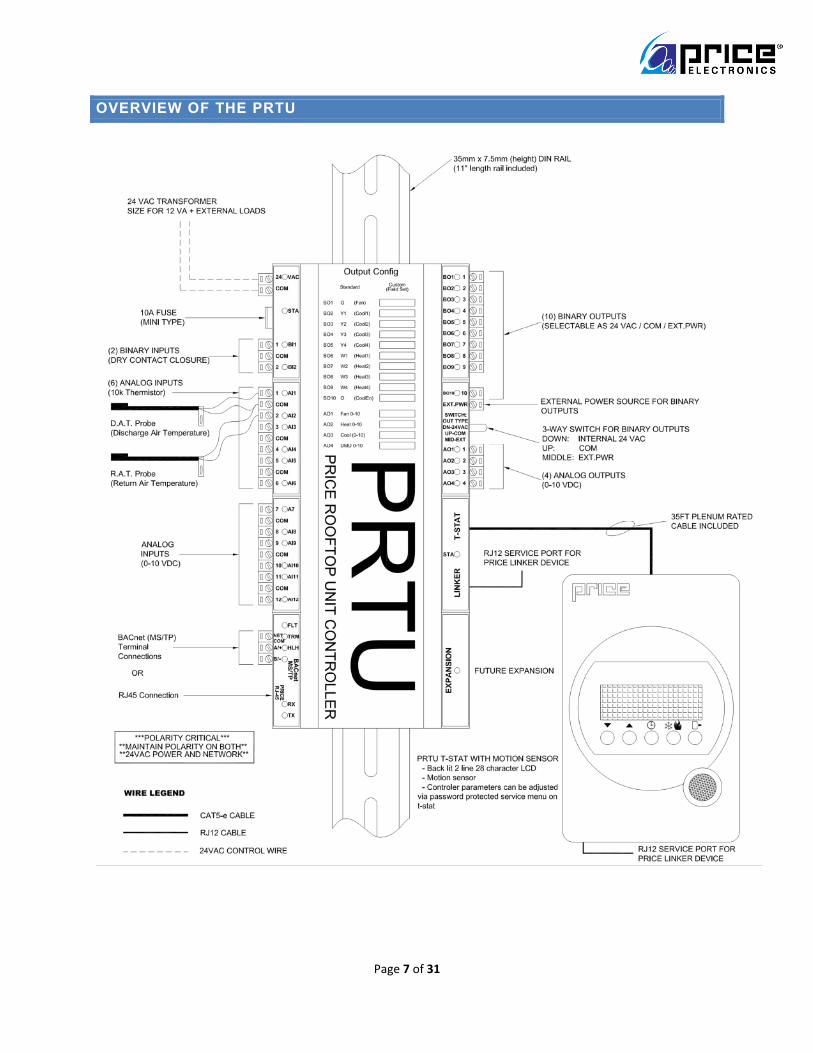
OVERVIEW OF THE PRTU

Page 8 of 31
INSTALLATION AND MOUNTING
PRTU CONTROLLER
To mount the PRTU controller use the included 11” piece of DIN rail. The PRTU must NOT be installed
outdoors or inside the RTU. Mount the PRTU in the PLENUM space. Ideally near the main ductwork
discharge/return of the RTU just above the ceiling tiles.
1. Using 3 screws (by others) mount the DIN rail horizontally to a secure, accessible surface
2. Hang the PRTU controller onto the DIN rail using the TOP white clips
3. Using the Price Electronics screwdriver, gently pull down on the BLACK clip, while pushing gently
on the PRTU towards the DIN rail.
4. The PRTU should click securely into place.
5. To remove, repeat above steps in reverse
DIN Rail
Back view of PRTU
Front view of PRTU mounted on DIN Rail

Page 9 of 31
PRTU THERMOSTAT
The PRTU Thermostat must be mounted to a wall and wired to the PIC controller via the supplied plenum rated 35ft CAT-5 cable. This cable plugs into the thermostat and the PRTU T-STAT jack with a RJ-45 connection. Note: the cable run can be extended to 70 ft using a Price cable coupler (NETCC) and additional 35ft cable (PIC-CABLE).
LOCATION
To mount the PRTU thermostat remove the back plate gently lifting from the bottom. Mount the back
plate/thermostat in common area such as a hallway. This allows the motion sensor to detect people
during unoccupied periods. Also if the system needs to operate in stand-alone mode (using the
thermostat temperature sensor) this allows adequate control of the RTU.
� Do not mount the thermostat in direct sunlight (ie: across from a window)
� Do not install on an exterior wall
� Do not mount near equipment that generates heat (monitors, fridge, photocopiers, etc)
� Ensure nothing will restrict vertical air circulation to the thermostat (ie: do not cover, enclose, etc)
� Ensure wall is NOT pressurized! Hot/cold air from a pressurized wall will directly blow onto the thermostat’s temperature sensor causing ‘bad’ readings.
INSTALLATION STEPS
1. The back plate on each thermostat is removable and can be mounted to a standard electrical box or directly to drywall using anchors supplied by others.
2. Run the CAT-5 cable through the center hole in the plate. Connect the cable to the thermostat, and then secure the thermostat onto the wall plate inserting the top portion of the thermostat first, and then snapping the bottom half in.
3. All thermostats will come equipped with a 0.050” Allen key for the set screw at the bottom. This helps secure the thermostat and prevents users from removing it.
TECH TIP: Careful thermostat installation will reduce field
issues! Do not twist or kink the blue CAT5 thermostat
cable. Damaged cables are difficult to troubleshoot!
Thermostat cable product code: PIC-CABLE

Page 10 of 31
WIRING
PRTU
Wiring of the PRTU to the packaged rooftop unit is simple, but still requires attention to detail. In virtually
all installations the PRTU will be powered from the RTU 24 VAC transformer. 24 VAC hot and common
polarities are critical and must be observed throughout the wiring process!
As with most 24 VAC powered devices, reversing polarity still allows the device to power up, but once
connected to another device undesirable results will occur. These are typically difficult to troubleshoot
and consume valuable time.
Below is a typical hookup to a 2 stage heat/cool unit with a binary fan.
C R G Y1 Y2 W1 W2
R = 24 VAC HOT
C = 24 VAC COMMON (earth grounded)
G = FAN (BO1)
Y1 = Cooling Stage 1 (BO2)
Y2 = Cooling Stage 2(BO3)
W1 = Heating Stage 1 (BO6)
W2 = Heating Stage 2 (BO7)
Ensure 24 VAC Polarity is correct and
consistent among all devices! Ensure 24 VAC
COMMON is Earth Grounded.

Page 11 of 31
PRTU THERMOSTAT
Plug thermostat cable into RJ45 Jack of thermostat and in RJ45 jack labeled T-STAT on PRTU.
Thermostat gets power from PRTU, which is getting 24 VAC from Rooftop unit. On power up thermostat
displays its firmware version V3.XX and PRTU firmware version V1.XX.

Page 12 of 31
ZONE POLLING VIA BACNET MS/TP NETWORK
The PRTU can poll zones for load data (room temperature and room set point) over a BACnet MS/TP
connection (aka the NETWORK). Price Controllers that support BACnet and zone control are currently
the Price Intelligent Controller (PIC) and Prodigy Smart Diffuser (PPD). To simplify the wiring of MS/TP
Price uses an RJ-45 connection. Pins 1 and 2 are used for the MS/TP data (+ and -), while Pins 7 and 8
are used for a BACnet common connection. Pins 3,4,5,6 are no connects. Please note this is not an
Ethernet connection! Price uses RJ45 jacks and cable due to their excellent specifications and
availability.
The PRTU has both a RJ45 connection and a 3 position terminal plug that can access the MS/TP port.
Typically you will use the RJ45 connection to connect to the ZONE CONTROLLERS.
Before networking to the controllers please use the checklist below:
� All zone controllers are powered up and functioning
� All zone controllers have consistent 24 VAC hot and 24 VAC common power correctly hooked up
� Each zone controller has a UNIQUE MAC address starting at 1 and going up to a maximum of
30.
� Each zone controller has a UNIQUE DEVICE INSTANCE address starting at 101 (going to 130)
� Each zone controller is running at a MS/TP baud rate of 76,800 (Price default for all controllers,
recommend you use this and do not change on any controllers).
� All controllers must be wired in DAISY CHAIN format. Controller to controller, no ‘T’ or split
connections
� Note: Bad wiring, Addresses, Baud Rates, etc will cause network to crash and/or be unreliable.
Triple check all wiring and settings! PRTU will run in stand-alone mode unless network is good.
Once errors are fixed PRTU will automatic switch back to networked mode.
BACnet ADDRESSING TIPS:
If only installing one PRTU please use the default addresses. Each PRTU has two address types a
LOCAL and a SYSTEM address.
On PRTU the LOCAL address (MAC address) is unique to the MS/TP segment and has a range of 101-
126. This ensure it does not collide with the Zone Controllers addresses (which are limited from 1-99)
On PRTU the SYSTEM address (DEVICE INSTANCE) is unique to the building network and has a range
of 1- 4.19M
PRTU DEFAULT – MAC - 101
PRTU DEFAULT – INSTANCE - 100

Page 13 of 31
NETWORKING - SYSTEM EXAMPLE
Up to
MAX 30
devices
PRTU
• Default – LOCAL/MAC – 101
• Default – SYSTEM/DEVICE INSTANCE
– 100
• Number of polling zones = 3
PIC – Zone Controller #1
Default – LOCAL/MAC – 1 Default – SYSTEM/INSTANCE - 101
PIC – Zone Controller #2
Default – LOCAL/MAC – 2 Default – SYSTEM/INSTANCE - 102
PIC – Zone Controller #3
Default – LOCAL/MAC – 3 Default – SYSTEM/INSTANCE - 103
Set the PRTU address using the WIZARD or BACnet menu. Set the PIC or Prodigy addresses using the DIP switches for LOCAL/MAC and the LCD Thermostat for setting the SYSTEM/INSTANCE (ADDRESS MENU). When changing DIP switches you must CYCLE POWER on the controller! Since the DIP switches are only read on startup. TIP: Press UP/DOWN buttons on LCD stat at same time, this will display the startup screen and show you the current address. (Works on PRTU, PIC and PRODIGY!)
Termination of MS/TP network: Each MS/TP network should
be terminated to prevent reflections and ensure a reliable
network. Terminate a total of 2 times, once at beginning of
network and once at the last device. In the example below,
enable termination at the PRTU (via the BACnet menu) and
the last PIC controller #3 using the DIP switch #8 (TRM).

Page 14 of 31
LCD THERMOSTAT – INITIAL START UP
When the LCD thermostat is first powered from the PRTU controller, it will display the following information: (Also press both UP/DOWN at same time to show this screen anytime.)
SERVICE MENU AND TIME/MODE BUTTONS
Menu Button – used to enter SERVICE MENU. Hold button for 5 seconds
to enter SERVICE. Passcode:
Note: It is the same passcode for SERVICE and TIME/MODE set buttons.
Start-up screen
PRTU Thermostat has LCD screen and motion sensor
LCD Thermostat - Firmware Version V3.xx or higher
Loading Screen – Thermostat pulls in variables from PRTU
Displays current MAC Address (local MS/TP segment) – Must be unique to
MS/TP segment
Displays current Device Instance (System address) – Must be unique to
building
PricePricePricePrice ElectronicsElectronicsElectronicsElectronics
LCD ThermostatLCD ThermostatLCD ThermostatLCD Thermostat Motion ModelMotion ModelMotion ModelMotion Model
LCD ThermostatLCD ThermostatLCD ThermostatLCD Thermostat Version Version Version Version 3333.XX.XX.XX.XX
Loading:Loading:Loading:Loading: 0000----100 %100 %100 %100 %
PRTUPRTUPRTUPRTU Version 1.XXVersion 1.XXVersion 1.XXVersion 1.XX
PRTU Controller - Firmware Version 1.xx or higher
MAC AddressMAC AddressMAC AddressMAC Address Local 101Local 101Local 101Local 101
Device Inst.Device Inst.Device Inst.Device Inst. System 100System 100System 100System 100
Device Inst.Device Inst.Device Inst.Device Inst. System 100System 100System 100System 100
After start up LCD will cycle between Current Mode, Time/Date and Room
Temperature (if in stand-alone – non-networked mode)
Down Button – used for menu selection and stand-alone set point
adjustment
Up Button – used for menu selection and stand-alone set point
adjustment – press both to display thermostat Startup screens
Time Set Button – used to set real time clock and calendar. Can be
password protected, but this is off by default.
Mode Set Button – used to set mode of the system. Can force Cooling
only, Heating only, Ventilation (fan) or Auto-changeover (default). Can be
password protected, but this is off by default.

Page 15 of 31
SERVICE MENU
The service menu contains all setup and configuration parameters. Each PRTU ships as a stand-alone
controller, in Fahrenheit units and is setup to control a 2 – stage heating and 2 – stage cooling packaged
rooftop unit with a binary fan. All MAIN menus are listed on this page. Use the WIZARD and/or below
menus to setup the PRTU for your application.
Service Menu:Service Menu:Service Menu:Service Menu: SetpointSetpointSetpointSetpoint
Press MenuPress MenuPress MenuPress Menu To To To To exitexitexitexit
Service Menu:Service Menu:Service Menu:Service Menu: StrategyStrategyStrategyStrategy
Service Menu:Service Menu:Service Menu:Service Menu: InputInputInputInput
Strategy Menu – allows setting of stand-alone and polling modes
See page 16-17 for details
Setpoint Menu – units, Night heat/cool, and limits
See page 18 for details
Input Menu – Tstat offset, reading of inputs (AI1-AI12)
See page 19 for details
Service Menu:Service Menu:Service Menu:Service Menu: OutputOutputOutputOutput
Output Menu – of binary and analog outputs
See page 20-21 for details
Service Menu:Service Menu:Service Menu:Service Menu: BACnetBACnetBACnetBACnet
BACnet Menu – BACnet addresses (MAC and System)
See page 22 for details
Service Menu:Service Menu:Service Menu:Service Menu: Stat SetupStat SetupStat SetupStat Setup
Stat Setup Menu – Motion Sensor setup, Time/mode password enable
See page 23 for details
Service Menu:Service Menu:Service Menu:Service Menu: DiagnosticDiagnosticDiagnosticDiagnostic
Diagnostic – Displays BACnet health, Zones up
See page 24 for details
Polling Menu – Set # of zones, zone weights, proportional band
See page 24 for details Service Menu:Service Menu:Service Menu:Service Menu:
PollingPollingPollingPolling
Service Menu:Service Menu:Service Menu:Service Menu: Time/Date SetTime/Date SetTime/Date SetTime/Date Set
Time/Date Set Menu – Setting of real time clock and calendar
See page 25 for details
Service Menu:Service Menu:Service Menu:Service Menu: Schedule SetSchedule SetSchedule SetSchedule Set
Schedule Set Menu – Setting of occupancy schedule
See page 26 for details
Service Menu:Service Menu:Service Menu:Service Menu: OperationOperationOperationOperation
Operation Menu – sets PRTU mode, Fan configuration, # of stages
See page 27 for details
Exit Menu – Exits back to main cycle screen
Setup Wizard – Steps the user through a simple setup process.
Intended to get PRTU up and running quickly. Wizard runs on first power
up, but can be re-run at any time.
Service Menu:Service Menu:Service Menu:Service Menu: SETUP WIZARDSETUP WIZARDSETUP WIZARDSETUP WIZARD
Page 16 of 31
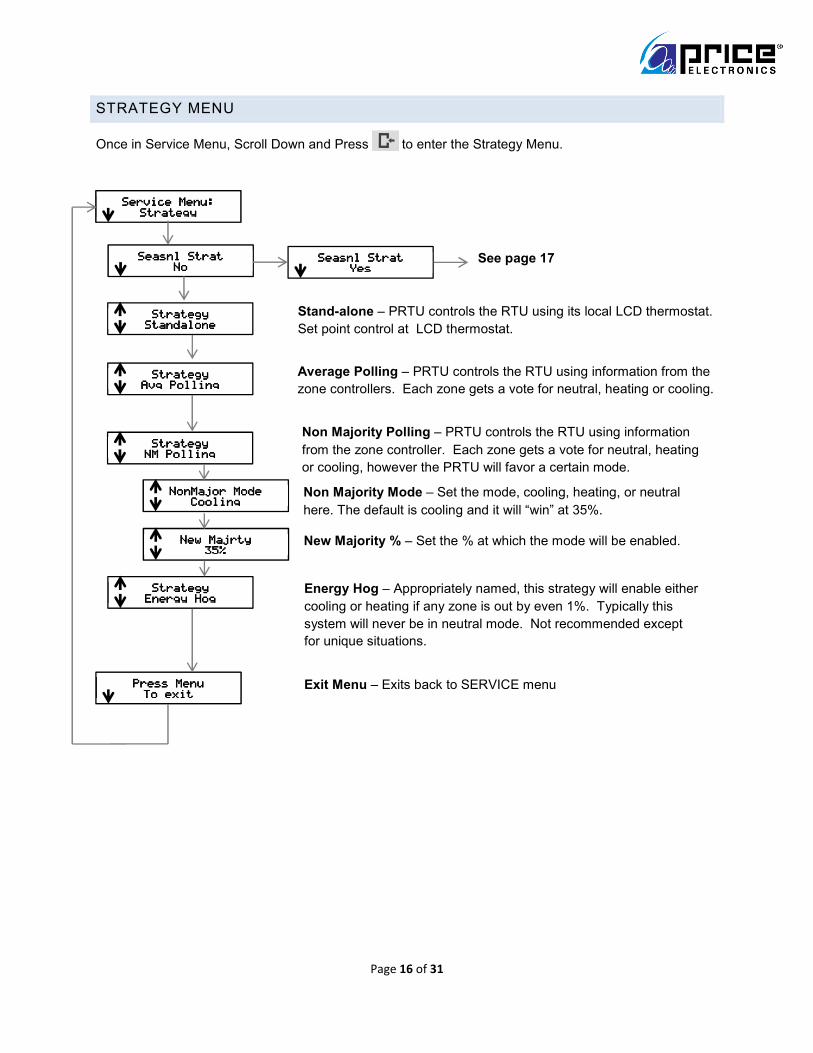
STRATEGY MENU
Once in Service Menu, Scroll Down and Press to enter the Strategy Menu.
Press MenuPress MenuPress MenuPress Menu To exitTo exitTo exitTo exit
Seasnl StratSeasnl StratSeasnl StratSeasnl Strat NoNoNoNo
StrategyStrategyStrategyStrategy StandaloneStandaloneStandaloneStandalone
Service Menu:Service Menu:Service Menu:Service Menu: StrategyStrategyStrategyStrategy
StrategyStrategyStrategyStrategy Avg PollingAvg PollingAvg PollingAvg Polling
StrategyStrategyStrategyStrategy NM PollingNM PollingNM PollingNM Polling
NonMajor ModeNonMajor ModeNonMajor ModeNonMajor Mode CoolingCoolingCoolingCooling
New MajrtyNew MajrtyNew MajrtyNew Majrty 35%35%35%35%
StrategyStrategyStrategyStrategy Energy HogEnergy HogEnergy HogEnergy Hog
Seasnl StratSeasnl StratSeasnl StratSeasnl Strat YesYesYesYes
See page 17
Exit Menu – Exits back to SERVICE menu
Stand-alone – PRTU controls the RTU using its local LCD thermostat.
Set point control at LCD thermostat.
Average Polling – PRTU controls the RTU using information from the
zone controllers. Each zone gets a vote for neutral, heating or cooling.
Non Majority Polling – PRTU controls the RTU using information
from the zone controller. Each zone gets a vote for neutral, heating
or cooling, however the PRTU will favor a certain mode.
Non Majority Mode – Set the mode, cooling, heating, or neutral
here. The default is cooling and it will “win” at 35%.
New Majority % – Set the % at which the mode will be enabled.
Energy Hog – Appropriately named, this strategy will enable either
cooling or heating if any zone is out by even 1%. Typically this
system will never be in neutral mode. Not recommended except
for unique situations.

Page 17 of 31
STRATEGY MENU – SEASONAL STRATEGY
Once in Service Menu, Scroll Down and Press to enter the Strategy Menu.
Then select Seasonal Strategy – Yes. This allows automatic changing of the strategy based on Spring,
Summer, Fall and Winter. For example you could favor cooling in summer, heating in winter and use
standard average polling for spring/fall. The intent is to allow the system to control optimally as the
seasons change.
Service Menu:Service Menu:Service Menu:Service Menu: StrategyStrategyStrategyStrategy
Seasnl StratSeasnl StratSeasnl StratSeasnl Strat YesYesYesYes
Spring Spring Spring Spring Strat.Strat.Strat.Strat. Avg PollingAvg PollingAvg PollingAvg Polling
Seasonal Strategy – Yes – enables auto strategy changed based on date
Spring Strategy – Sets strategy based on season. (Stand-alone, Average
Polling, Non majority polling, Energy Hog) Default: Avg Polling.
Spring MonthSpring MonthSpring MonthSpring Month 3333
Spring Month – Sets month start date of strategy selected. Range 1 -12
(January to December)
Spring DaySpring DaySpring DaySpring Day 1111
Spring Day – Sets Day start date of strategy selected. Range 1 – 31.
Summer, FallSummer, FallSummer, FallSummer, Fall WinterWinterWinterWinter
Summer, fall, and winter – menus repeat for the other 3 seasons.
Press MenuPress MenuPress MenuPress Menu To exitTo exitTo exitTo exit
Exit Menu – Exits back to SERVICE menu

Page 18 of 31
SETPOINT MENU
Once in Service Menu, Scroll Down and Press to enter the Set point Menu.
Press MenuPress MenuPress MenuPress Menu ToToToTo exitexitexitexit
Service Menu:Service Menu:Service Menu:Service Menu: SetpointSetpointSetpointSetpoint
SetpointSetpointSetpointSetpoint StandaloneStandaloneStandaloneStandalone
Temp. UnitsTemp. UnitsTemp. UnitsTemp. Units FahrenheitFahrenheitFahrenheitFahrenheit
Nite Heat SetNite Heat SetNite Heat SetNite Heat Set 62.0 F62.0 F62.0 F62.0 F
Nite Cool SetNite Cool SetNite Cool SetNite Cool Set 83.0 F83.0 F83.0 F83.0 F
Set Lo LimitSet Lo LimitSet Lo LimitSet Lo Limit 65.0 F65.0 F65.0 F65.0 F
Set Hi LimitSet Hi LimitSet Hi LimitSet Hi Limit 80.0 F80.0 F80.0 F80.0 F
Pro. BandPro. BandPro. BandPro. Band 2.0 F2.0 F2.0 F2.0 F
Night Cool Setpoint – The system will maintain this cooling set point in
unoccupied mode (ie: at night)
Day Diff.Day Diff.Day Diff.Day Diff. 1.0 F1.0 F1.0 F1.0 F
SP SeparationSP SeparationSP SeparationSP Separation 4.0 F4.0 F4.0 F4.0 F
IntegralAdderIntegralAdderIntegralAdderIntegralAdder 5 %5 %5 %5 %
PI overshootPI overshootPI overshootPI overshoot None/SP/DeadbndNone/SP/DeadbndNone/SP/DeadbndNone/SP/Deadbnd
Night Heat Setpoint – The system will maintain this heating set point in
unoccupied mode (ie: at night)
Temp Units – The system temperature units are set here. ***NOTE: All
zones must be in the same units as PRTU to properly control!***
Set point – Standalone or Polling – Allows adjustment of stand-alone
and polling Setpoints
Low Set point Limit – User cannot adjust
lower than this setting
High Set point Limit – User cannot
adjust higher than this setting
Proportional Band – sets the stand-
alone proportional band.
Day Differential – aka Deadband –
system will not control if within 1 F of
setpoint
Setpoint Sep – Forces a 4.0F separation
between cooling and heating setpoints
Integral Adder – Every 2 minutes 5% is
added to the Integral until setpoint is met.
PI overshoot –
None – system satisfied if room temp.
within deadband. (ie: 72.0F +-1F)
To Setpoint – system satisfied if room
temp. matches deadband
Entire Deadband - system satisfied if
room temp. matches SP+deadband
Note – The system will turn on if ANY zone hits the night heat or cool
Setpoint. If there is a call for both heat/cool – heat wins.

Page 19 of 31
INPUT MENU
Once in Service Menu, Scroll Down and Press to enter the Input Menu.
Service Menu:Service Menu:Service Menu:Service Menu: InputInputInputInput
TTTT----stat Temp.stat Temp.stat Temp.stat Temp. 72.0 F72.0 F72.0 F72.0 F
TTTT----stat Offsetstat Offsetstat Offsetstat Offset 0.0 F0.0 F0.0 F0.0 F
DAT (AI1)DAT (AI1)DAT (AI1)DAT (AI1) ----59.0 F59.0 F59.0 F59.0 F
RAT (AI2)RAT (AI2)RAT (AI2)RAT (AI2) ----59.0 F59.0 F59.0 F59.0 F
T-Stat Temperature – Current PRTU stat temperature
T-Stat Offset – Allows offset of T-stat thermistor. Typically not
recommended. Default: +-0.0F
RAT – Return Air Temperature sensor. This sensor is included with
PRTU and should be installed in the return duct to RTU. Helps prevent
tripping of safeties (heating and cooling) if return exceeds limits. This
can occur with a ducted bypass and VAV zones. Will read -59.0F if not
connected. PRTU will IGNORE if reading is -59.0 F and control
normally. +300.0 F means a short circuit in wiring or damaged probe.
Disconnect and replace ASAP.
DAT – Discharge Air Temperature sensor. This sensor is included with
PRTU and should be installed in the discharge/supply duct of RTU.
This feedback helps limit excessive temperature swings with large and
oversized equipment. Will read -59.0F if not connected. PRTU will
IGNORE if reading is -59.0 F and control normally. +300.0 F means a
short circuit in wiring or damaged probe. Disconnect and replace
ASAP.
AI3AI3AI3AI3----AI6AI6AI6AI6 ----59.0 F59.0 F59.0 F59.0 F
AI3 – AI6 – Analog inputs 3,4,5,6 are 10k type J inputs and are
currently only used for monitoring. Extra probes can be installed to
monitor other temperatures. These points are available for monitoring
and logging over BACnet. However they do not affect control. Range: -
59.0 F - +300.0 F.
AI7AI7AI7AI7----AI12AI12AI12AI12 0000----10 VDC10 VDC10 VDC10 VDC
AI7 – AI12 – Analog inputs 7,8,9,10, 11, 12 are 0-10 VDC inputs and
are currently only used for monitoring. Extra sensors can be installed to
monitor other voltages. These points are available for monitoring and
logging over BACnet. However they do not affect control. Range: 0-10
VDC.
Press MenuPress MenuPress MenuPress Menu To exitTo exitTo exitTo exit

Page 20 of 31
OUTPUT MENU – BINARY
Once in Service Menu, Scroll Down and Press to enter the Output Menu.
Service Menu:Service Menu:Service Menu:Service Menu: OutputOutputOutputOutput
OutputOutputOutputOutput Binary OutputBinary OutputBinary OutputBinary Output
BO1 UsageBO1 UsageBO1 UsageBO1 Usage Default: FanDefault: FanDefault: FanDefault: Fan
Binary OutputBinary OutputBinary OutputBinary Output TimingTimingTimingTiming
Binary OutputBinary OutputBinary OutputBinary Output Output PinsOutput PinsOutput PinsOutput Pins
BO1 – Default – RTU FAN – Each BO1-10
can be re-tasked to either:
• Fan
• Cool 1 (stage 1)
• Cool 2 (stage 2)
• Cool 3 (stage 3)
• Cool 4 (stage 4)
• Heat 1 (stage 1)
• Heat 2 (stage 2)
• Heat 3 (stage 3)
• Heat 4 (stage 4)
• Cool Enable (active on cooling)
• Heat Enable (active on heating)
BO2 UsageBO2 UsageBO2 UsageBO2 Usage Default: Cool1Default: Cool1Default: Cool1Default: Cool1
BO3 UsageBO3 UsageBO3 UsageBO3 Usage Default: Cool2Default: Cool2Default: Cool2Default: Cool2
BO4 UsageBO4 UsageBO4 UsageBO4 Usage Default: Cool3Default: Cool3Default: Cool3Default: Cool3
BO5 UsageBO5 UsageBO5 UsageBO5 Usage Default: Cool4Default: Cool4Default: Cool4Default: Cool4
BO6 BO6 BO6 BO6 UsageUsageUsageUsage Default: Heat1Default: Heat1Default: Heat1Default: Heat1
BO7 UsageBO7 UsageBO7 UsageBO7 Usage Default: Heat2Default: Heat2Default: Heat2Default: Heat2
BO8 UsageBO8 UsageBO8 UsageBO8 Usage Default: Heat3Default: Heat3Default: Heat3Default: Heat3
BO9 UsageBO9 UsageBO9 UsageBO9 Usage Default: Heat4Default: Heat4Default: Heat4Default: Heat4
BO10 UsageBO10 UsageBO10 UsageBO10 Usage Default: Cool En.Default: Cool En.Default: Cool En.Default: Cool En.
Min On timeMin On timeMin On timeMin On time 60 Sec.60 Sec.60 Sec.60 Sec.
Min Off timeMin Off timeMin Off timeMin Off time 300 Sec.300 Sec.300 Sec.300 Sec.
Minimum On time – This is the minimum time the binary output
can be on. (regardless of temperature control/etc)
Minimum Off time – This is the minimum time the binary output
will be off. (regardless of temperature control/etc) Intended to
prevent short cycling of equipment.
Press MenuPress MenuPress MenuPress Menu To exitTo exitTo exitTo exit
Press MenuPress MenuPress MenuPress Menu To exitTo exitTo exitTo exit
OutputOutputOutputOutput Analog OutputAnalog OutputAnalog OutputAnalog Output
See page 21 for
Output – Analog

Page 21 of 31
OUTPUT MENU - ANALOG
Once in Service Menu, Scroll Down and Press to enter the Output Menu.
Service Menu:Service Menu:Service Menu:Service Menu: OutputOutputOutputOutput
OutputOutputOutputOutput Binary OutputBinary OutputBinary OutputBinary Output
Fan cool MinFan cool MinFan cool MinFan cool Min 2.0 VDC2.0 VDC2.0 VDC2.0 VDC
Analog OutputAnalog OutputAnalog OutputAnalog Output FanFanFanFan
FAN – AO1 – All fan voltages are tied to
the PI controller and occupancy. Each
mode can be set between 0 – 10 VDC.
Cooling mode the PI controller is between
-100% to -1%. Heating mode the PI
controller is between +100% to +1%.
Fan cool MaxFan cool MaxFan cool MaxFan cool Max 10.0 VDC10.0 VDC10.0 VDC10.0 VDC
Fan Heat MinFan Heat MinFan Heat MinFan Heat Min 2.0 VDC2.0 VDC2.0 VDC2.0 VDC
Fan Heat MaxFan Heat MaxFan Heat MaxFan Heat Max 10.0 VDC10.0 VDC10.0 VDC10.0 VDC
Fan DeadbandFan DeadbandFan DeadbandFan Deadband 2.0 VDC2.0 VDC2.0 VDC2.0 VDC
Fan Unocc.Fan Unocc.Fan Unocc.Fan Unocc. 0.0 VDC0.0 VDC0.0 VDC0.0 VDC
Press MenuPress MenuPress MenuPress Menu To exitTo exitTo exitTo exit
OutputOutputOutputOutput Analog OutputAnalog OutputAnalog OutputAnalog Output
See page 20
for Output –
Binary
Fan Deadband – output when PI = 0% -
satisfied
Fan Unoccupied – output when PRTU
is unoccupied
Analog OutputAnalog OutputAnalog OutputAnalog Output
HeatHeatHeatHeat
Ana. Heat MinAna. Heat MinAna. Heat MinAna. Heat Min 0.0 VDC0.0 VDC0.0 VDC0.0 VDC
Ana. Heat MaxAna. Heat MaxAna. Heat MaxAna. Heat Max 0.0 VDC0.0 VDC0.0 VDC0.0 VDC
Ana. Heat IdleAna. Heat IdleAna. Heat IdleAna. Heat Idle 0.0 VDC0.0 VDC0.0 VDC0.0 VDC
Analog OutputAnalog OutputAnalog OutputAnalog Output CoolCoolCoolCool
Analog OutputAnalog OutputAnalog OutputAnalog Output AuxAuxAuxAux
Analog Heat Minimum – output when
PI = just enters heating
Analog Heat Maximum – output when
PI = max heating
Analog Heat Idle – output when PI =
0% or cooling
Press MenuPress MenuPress MenuPress Menu To exitTo exitTo exitTo exit
Press MenuPress MenuPress MenuPress Menu To exitTo exitTo exitTo exit
Ana. Cool MinAna. Cool MinAna. Cool MinAna. Cool Min 0.0 VDC0.0 VDC0.0 VDC0.0 VDC
Ana. Cool MaxAna. Cool MaxAna. Cool MaxAna. Cool Max 0.0 VDC0.0 VDC0.0 VDC0.0 VDC
Ana. Cool IdleAna. Cool IdleAna. Cool IdleAna. Cool Idle 0.0 VDC0.0 VDC0.0 VDC0.0 VDC
Press MenuPress MenuPress MenuPress Menu To exitTo exitTo exitTo exit
Analog Cool Minimum – output when
PI = just enters cooling
Analog Cool Idle – output when PI =
0% or heating
Analog Cool Maximum – output when
PI = max cooling
Aux – spare
output (AO4)
Page 22 of 31
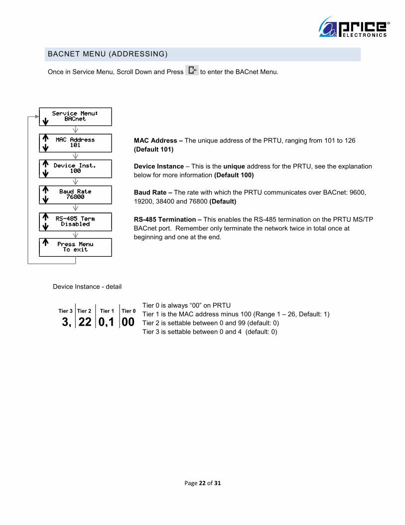
BACNET MENU (ADDRESSING)
Once in Service Menu, Scroll Down and Press to enter the BACnet Menu.
Tier 3 Tier 2 Tier 1 Tier 0
3, 22 0,1 00
Tier 0 is always “00” on PRTU
Tier 1 is the MAC address minus 100 (Range 1 – 26, Default: 1)
Tier 2 is settable between 0 and 99 (default: 0)
Tier 3 is settable between 0 and 4 (default: 0)
Service Menu:Service Menu:Service Menu:Service Menu: BACnetBACnetBACnetBACnet
Press MenuPress MenuPress MenuPress Menu To exitTo exitTo exitTo exit
RSRSRSRS----485 Term485 Term485 Term485 Term DisabledDisabledDisabledDisabled
RS-485 Termination – This enables the RS-485 termination on the PRTU MS/TP
BACnet port. Remember only terminate the network twice in total once at
beginning and one at the end.
MAC AddressMAC AddressMAC AddressMAC Address 101101101101
MAC Address – The unique address of the PRTU, ranging from 101 to 126
(Default 101)
Device Inst.Device Inst.Device Inst.Device Inst. 100100100100
Device Instance – This is the unique address for the PRTU, see the explanation
below for more information (Default 100)
Baud RateBaud RateBaud RateBaud Rate 76800768007680076800
Baud Rate – The rate with which the PRTU communicates over BACnet: 9600,
19200, 38400 and 76800 (Default)
Device Instance - detail

Page 23 of 31
STAT SETUP MENU
Once in Service Menu, Scroll Down and Press to enter the Stat Setup Menu.
Service Menu:Service Menu:Service Menu:Service Menu: Stat SetupStat SetupStat SetupStat Setup
Press MenuPress MenuPress MenuPress Menu To exitTo exitTo exitTo exit
OccupancyOccupancyOccupancyOccupancy Sch. OccupiedSch. OccupiedSch. OccupiedSch. Occupied
Occupancy – Displays the current reason the space is occupied (This is a read only variable)
Motion EnableMotion EnableMotion EnableMotion Enable OnOnOnOn
Motion Enable – If motion is detected, occupancy is set Motion T-Stat only
SensitivitySensitivitySensitivitySensitivity 5555
Sensitivity – Sets how sensitive the motion T-Stat is, ranges from 1 (least sensitive) to 9 (most sensitive) (Default 5) Motion T-Stat only
Motion TestMotion TestMotion TestMotion Test OffOffOffOff
Motion Test – Tests the motion sensor, when motion is detected the T-Stat will beep Default Off – Motion T-Stat only
LCD BacklightLCD BacklightLCD BacklightLCD Backlight Always OnAlways OnAlways OnAlways On
LCD Back Light – Sets how the back lighting works, Button Push, Always Off or Always On (Default)
Sound OptionsSound OptionsSound OptionsSound Options OnOnOnOn
Sound Options – Changes how the sounds work, On (Default), Off, or Diagnostic
Time PasswordTime PasswordTime PasswordTime Password DisabledDisabledDisabledDisabled Time Password – This protects the TIME push button with the service passcode
Mode PasswordMode PasswordMode PasswordMode Password DisabledDisabledDisabledDisabled
Mode Password - This protects the MODE push button with the service
passcode

Page 24 of 31
DIAGNOSTIC MENU
Once in Service Menu, Scroll Down and Press to enter the Diagnostic Menu.
POLLING MENU
Once in Service Menu, Scroll Down and Press to enter the Polling Menu.
Service Menu:Service Menu:Service Menu:Service Menu: DiagnosticDiagnosticDiagnosticDiagnostic
Press MenuPress MenuPress MenuPress Menu To exitTo exitTo exitTo exit
BACnet HealthBACnet HealthBACnet HealthBACnet Health
BACnet Health – This shows the current state of the MS/TP network. No connection means no devices detected (Yellow LED), 0-99% means devices detected but errors are present (Red LED), 100% means a proper healthy network is up.(Green LED)
Load DefaultsLoad DefaultsLoad DefaultsLoad Defaults Load Defaults – Resets the PRTU back to the factory defaults. NOTE: This will clear ALL settings!
Service Menu:Service Menu:Service Menu:Service Menu: PollingPollingPollingPolling
Press MenuPress MenuPress MenuPress Menu To exitTo exitTo exitTo exit
# of Zones# of Zones# of Zones# of Zones 1111
Number of Zones – Sets the expected number of controllers that the PRTU will expect to see Default 1, Range 1-30
DifferentialDifferentialDifferentialDifferential 1.0 1.0 1.0 1.0 º FFFF
Differential – Dead band on each side of set point Default 1.0 ºF, 0.5 ºC
Prop. BandProp. BandProp. BandProp. Band 2.0 2.0 2.0 2.0 º FFFF Proportional Band – Proportional band Default 2 ºF, 1 ºC
Zone SelectZone SelectZone SelectZone Select 1111
Zone Select – Used with Zone Weight to select a specific zone Default 1
Zone1 WeighZone1 WeighZone1 WeighZone1 Weightttt 1111
Zone Weight – Sets the number of weight or “votes” for the selected zone Default 1

Page 25 of 31
TIME/DATE SET MENU
Once in Service Menu, Scroll Down and Press to enter the Time/Date Set Menu.
Service Menu:Service Menu:Service Menu:Service Menu: Time/Date SetTime/Date SetTime/Date SetTime/Date Set
Press MenuPress MenuPress MenuPress Menu To exitTo exitTo exitTo exit
Set HourSet HourSet HourSet Hour Set Hour – Changes the current hour
Set MinuteSet MinuteSet MinuteSet Minute Set Minute – Changes the current minute
Set WeekdaySet WeekdaySet WeekdaySet Weekday Set Weekday – Changes the current day of the week
Set DaySet DaySet DaySet Day Set Day – Changes the current day of the month
Set MonthSet MonthSet MonthSet Month Set Month – Changes the current month
Set YearSet YearSet YearSet Year Set Year – Sets the current year
Clock ModeClock ModeClock ModeClock Mode Clock Mode – Choose between 12 hour and 24 hour formatted time Default 12 hour

Page 26 of 31
SCHEDULE MENU
Once in Service Menu, Scroll Down and Press to enter the Schedule Menu.
Sun #ON TimesSun #ON TimesSun #ON TimesSun #ON Times 1111
Service Menu:Service Menu:Service Menu:Service Menu: Schedule SetSchedule SetSchedule SetSchedule Set
Press MenuPress MenuPress MenuPress Menu To exitTo exitTo exitTo exit
Day SelectDay SelectDay SelectDay Select SundaySundaySundaySunday
Day Select – Select current day for schedule setup
Sun Hour ONSun Hour ONSun Hour ONSun Hour ON 6 AM6 AM6 AM6 AM
Sun Hour On – Sets system HOUR ON (occupied) time.
Sun Min OnSun Min OnSun Min OnSun Min On 0000
Sun Minutes On - Sets system MINUTE ON (occupied) time.
Sun Hour OFFSun Hour OFFSun Hour OFFSun Hour OFF 8 PM8 PM8 PM8 PM
Sun Hour Off - Sets system HOUR OFF (unoccupied) time.
Sun Min OFFSun Min OFFSun Min OFFSun Min OFF 0000
Sun Minimum Off - Sets system MINUTE OFF (unoccupied) time.
Sun Number On Times – Sets whether schedule is active on this day. 1 =
schedule will be active, 0 = schedule will be OFF that day.
Menus repeat for Menus repeat for Menus repeat for Menus repeat for MONMONMONMON----SATSATSATSAT
MON - SAT – menus repeat for Monday through Saturday

Page 27 of 31
OPERATION MENU
Once in Service Menu, Scroll Down and Press to enter the Operation Menu.
Service Menu:Service Menu:Service Menu:Service Menu: OperationOperationOperationOperation
Press MenuPress MenuPress MenuPress Menu To exitTo exitTo exitTo exit
Auto ChngoverAuto ChngoverAuto ChngoverAuto Chngover Auto Changeover – Sets the RTU mode, auto changeover for auto heat/cool
cycle, HEAT only, COOL only, FAN/Ventilation only, OFF – disable system
Fan ConfigFan ConfigFan ConfigFan Config Day/NightDay/NightDay/NightDay/Night
Fan Configuration – Day/Night – fan run during occupied, off at night, On Demand – fan runs when needed, 24/7 – fan runs continuously
# Cooling Stg# Cooling Stg# Cooling Stg# Cooling Stg 2222
Number of Cooling Stages – Sets the number of stages of cooling available between 1 to 4 – Default 2
# Heating Stg# Heating Stg# Heating Stg# Heating Stg 2222
Number of Heating Stages – Sets the number of stages of heating available between 1 and 4 - Default 2
Fan Prty TimeFan Prty TimeFan Prty TimeFan Prty Time 5 min.5 min.5 min.5 min.
Fan Priority Time – sets the minimum time the fan will run before cooling/heating stages have fired and after they’ve turned off. This helps prevent the RTU burner/coils/DX from tripping their local safeties when the main fan turns off/on.
H/C ON DelayH/C ON DelayH/C ON DelayH/C ON Delay 4 min.4 min.4 min.4 min.
Heating/Cooling ON Delay – Mode Change delay from dead band into H/C. Waits this amount of time to enter heat or cool mode from dead band. Also minimum time between stages energizing 1 thru 4 (ie: 4 minutes to energize first stage from deadband, and 4 minutes for each additional stage)
H/C OFF DelayH/C OFF DelayH/C OFF DelayH/C OFF Delay 2 min.2 min.2 min.2 min.
Heating/Cooling OFF Delay – Mode Change delay from H/C into dead band. Waits this amount of time to enter dead band from heating or cooling.
Chngover DelayChngover DelayChngover DelayChngover Delay 15 min.15 min.15 min.15 min.
Changeover Delay – This is the delay the unit must wait between switching
between heating and cooling modes. Intent is to prevent unnecessary cycling.
Mot. OverrideMot. OverrideMot. OverrideMot. Override 240 min.240 min.240 min.240 min.
Motor Override – If motion is enabled and detected during unoccupied periods
the system will switch to occupied for this amount of time.
DAT Hot Trip1DAT Hot Trip1DAT Hot Trip1DAT Hot Trip1 135.0135.0135.0135.0ºFFFF
DAT Hot Trip 1 – This sets the limit on the DAT probe. Stages 2-4 of Heat will
be disabled to not exceed this limit. Stage 1 is left active.
DAT Hot Trip2DAT Hot Trip2DAT Hot Trip2DAT Hot Trip2 145.0145.0145.0145.0ºFFFF
DAT Hot Trip 2 - This sets the hard limit on the DAT probe. All stages of Heat will be disabled to not exceed this limit. (1 thru 4)
RAT Hot Trip1RAT Hot Trip1RAT Hot Trip1RAT Hot Trip1 120.0120.0120.0120.0ºFFFF
RAT Hot Trip 1 - This sets the limit on the RAT probe. Stages 2-4 of Heat will be disabled to not exceed this limit. Stage 1 is left active.
RAT Hot Trip2RAT Hot Trip2RAT Hot Trip2RAT Hot Trip2 125.0125.0125.0125.0ºFFFF
RAT Hot Trip 2 - This sets the hard limit on the RAT probe. All stages of Heat will be disabled to not exceed this limit. (1 thru 4)
Cycle Thru Cool Cycle Thru Cool Cycle Thru Cool Cycle Thru Cool trip pointstrip pointstrip pointstrip points
Cool Trip Points – This sets the cooling trip points (same as HOT side)

Page 28 of 31
WIZARD MENU
Once in Service Menu, Scroll Down and Press to enter the Wizard Menu.
Service Menu:Service Menu:Service Menu:Service Menu: WizardWizardWizardWizard
Press MenuPress MenuPress MenuPress Menu To exitTo exitTo exitTo exit
Welcome!Welcome!Welcome!Welcome! SETUP WIZARDSETUP WIZARDSETUP WIZARDSETUP WIZARD
SETUP WIZARD – Press MENU key to advance through the wizard
SETUP WIZARDSETUP WIZARDSETUP WIZARDSETUP WIZARD Time/DateTime/DateTime/DateTime/Date
Time/Date – Set all time and date information
SETUP WIZARDSETUP WIZARDSETUP WIZARDSETUP WIZARD OperationOperationOperationOperation Operation – Setup of the # of stages, Strategy, etc
SETUP WIZARDSETUP WIZARDSETUP WIZARDSETUP WIZARD BACNETBACNETBACNETBACNET
BACnet – Setup of BACnet settings such as RTU #/MAC, number of polled zones
SETUP WIZARDSETUP WIZARDSETUP WIZARDSETUP WIZARD COMPLETE!COMPLETE!COMPLETE!COMPLETE!
Complete – PRTU has been setup and will now re-boot to apply all settings, Thermostat will re-boot as well.
Note – The Wizard will force you to go through all settings in order. You can re-run the wizard at any time.

Page 29 of 31
TROUBLESHOOTING
Problem Symptom Solution
Doesn't
Power On
All lights are off (including
24 VAC LED)
Check & Replace the fuse with a standard 10 amp automotive
style fuse. Check for 24 VAC +-10%.
BACnet
doesn't
communicate
BACnet TX light is blinking
green, RX is off
Ensure all BACnet cables are connected between everything on
the local BACnet network
BACnet does not share a
common reference
Ensure all units that are connected via the local BACnet network
share a common ground (Earth)
connection and that A(+) and B(-) are connected correctly
BACnet HLH LED is Red
The PRTU is detecting traffic, but it is all corrupted. Check that the
network length is below 1050 feet. All baud rates are the same,
each device has a unique MAC and INSTANCE.
BACnet HLH LED is solid
Yellow
The PRTU is detecting traffic, but it is partially corrupted. Check
that the network length is below 1050 feet. All baud rates are the
same, each device has a unique MAC and INSTANCE.
BACnet HLH LED is
blinking Yellow
Ensure all BACnet cables are connected between everything on
the local BACnet network. This says the PRTU detects no
devices whatsoever.
Binary
Output
isn't working
Power selector switch is
set incorrectly
The power selector switch needs to be fully down to switch 24
VAC, fully up to switch ground and in the
middle to switch external power
Corresponding LED is red The output is shorted, this will have to be resolved for normal
operation.
Corresponding LED is
blinking yellow
There is a BACnet override in place, that is forcing it off, this will
have to be removed for the unit to control the output
Corresponding LED is solid
yellow
There is a BACnet override in place, that is forcing it on, this will
have to be removed for the unit to control the output

Page 30 of 31
Analog input
isn't working
Corresponding LED is solid
yellow
There is a BACnet override in place, this will have to be removed
for the input to respond as expected
Corresponding LED is red
(0-10 Input) The voltage to the input is exceeding 10 VDC. In
addition, if the voltage is sufficiently high, it will cause corruption to
the other Analog Inputs
(Temperature Input) The temperature being read is over 250 ºF
(120 ºC), check the attached temperature probe. Price
temperature probes should read 10,000 ohms at 77F (25C).
Analog
output
isn't working
Corresponding LED is solid
yellow
There is a BACnet override in place, this will have to be removed
for the output to respond as expected
Corresponding LED is
blinking yellow
There is a BACnet override in place forcing the output off, this will
have to be removed for the output to
respond as expected
Corresponding LED is red There is a short on the output, it will have to be fixed before the
output will work as expected
T-Stat isn't
working
T-Stat is not turning on Check that the cable is plugged into both the T-Stat and the PRTU
STA LED next to T-Stat
port is Yellow The PRTU is unable to detect the T-Stat, check the cable
STA LED next to T-Stat
port is blinking Yellow
The temperature probe in the T-Stat is shorted, check the cable
and the T-Stat
STA LED next to T-Stat
port is Red The temperature sensor in the T-Stat is shorted out

® Price is a registered trademark of E.H. Price Limited. © 2011. Printed in Canada 2011
Grilles & Diffusers Critical Environments Terminals Sustainable Building Noise Control
w w w . p r i c e - h v a c . c o m
The founding principles of our company have never changed - business integrity, first class service and a commitment to people. Price manufacturing endeavors arose from our belief that we could supply superior products and services at a reasonable price. Our mission is to become the world-wide supplier of preference for air distribution products and services. You can rely on Price – our products and services – with confidence.
Warranty: The Company warrants and guarantees that all goods within this catalog that have been manufactured by the Company have been manufactured in accordance with the specifications published herein and will be free from defects in material and workmanship for a period of twelve (12) months from the date of Bill of Lading issued by the Company. The Company will replace defective product at its option, but will not be responsible for labor or material charges in replacing product or consequential damages. Any installation not conforming with the Company's specifications, manuals, bulletins or instructions or any misuse or any modification not authorized by the Company voids this warranty. This warranty is in lieu of all Provincial, State, and Federal statutory warranties and the conditions herein are in substitution and replacement of such warranties, statutory or otherwise.
2975 Shawnee Ridge Court
Suwanee, Georgia USA 30024
Ph: 770.623.8050 Fax: 770.623.6404
1290 Barrow Industrial Parkway
Auburn, Georgia USA 30011
638 Raleigh Street
Winnipeg, Manitoba Canada R2K 3Z9
Ph: 204.669.4220 Fax: 204.663.2715
999 North Thornton Road
Casa Grande, Arizona USA 85222-3809
Your Local Price Representative: