primary and secondary control for high penetration renewables · primary and secondary control for...
TRANSCRIPT

20 March 2012 1
Primary and Secondary Controlfor High Penetration Renewables
A Broad Analysis White Paper prepared for the projectA Broad Analysis White Paper prepared for the project
““The Future Grid to EnableThe Future Grid to EnableSustainable Energy SystemsSustainable Energy Systems””
Funded by the U.S. Department of EnergyFunded by the U.S. Department of Energy
White Paper Team:White Paper Team:Chris Chris DeMarcoDeMarco, , Chaitayna BaoneChaitayna Baone, , Yehui Yehui Han, Han, Bernie Bernie LesieutreLesieutre
University of Wisconsin-MadisonUniversity of Wisconsin-Madison
PSerc Webinar Series

20 March 2012 2
Synopsis
• Argue for new control design philosophy, to allowrenewables to more broadly contribute to grid activepower & frequency control.
• Move beyond present approaches that focus on makingrenewables mimic characteristics of traditionalturbine/synchronous generator sets.
• Exploit opportunities in improved grid measurement &sensor technologies (i.e, PMUs) to facilitate designsbased on optimal control. Tailor to specific (and verydifferent !!) dynamic characteristics of renewables.

20 March 2012 3
Motivation and Background
• Large scale renewable generation growthsuggests potential/need for correspondinggrowth for its role in grid control;
• Voltage/Var control aspects of renewablesalready seeing emerging standards;
• Premise here: new challenges and opportunitiestoday lie in control related to active power,frequency, and electromechanical stability.

20 March 2012 4
Motivation and Background(including indulgence of presenter’s own background…)
• In islanded, off-grid applications, coordination of windMW control w/ synchronous generators has long history.
• Large-scale grid applications may be new, and hardwareradically changed, but late 70’s early 80’s saw muchresearch on active power & frequency control for wind.
• This literature includes a certain 1980 MITundergraduate thesis, reporting results of arduoussummer field work on the Cape Cod island of Cuttyhunk.

20 March 2012 5
(Personal) Motivation

20 March 2012 6
Cuttyhunk IslandWind Turbine,circa 1980. Notvisible in this postcardphoto is a load bank ofthyristor-controlledresistors.
These provided widebandwidth active powercontrol, to coordinatew/ primary governorsof diesel-drivensynchronousgenerators on island.

20 March 2012 7
Motivation and Background
In context of active power/frequency regulation,control broadly classified in two categories:
“Primary Control” predominantly local, fast timescale automatic feedback on individual units.Design may be coordinated, action is individual.
“Secondary Control” is wider-area action, quasi-static, on slower time scale. Control is focusedon coordination across many units.

20 March 2012 8
What Distinguishes TraditionalGeneration Sources?
• Consider traditional contributors to active power &frequency. Almost all synchronous generators, drivenby turbines with valve-controlled gas or fluid flow (water,steam, natural gas).
Key features from control dynamics perspective:(i) turbine’s input mechanical shaft power is controllable(range & speed of valving distinguish different classes);
(ii) the inherent physics of synchronous generator forcesexact coupling of mechanical rotational speed & terminalelectrical frequency.

20 March 2012 9
What Distinguishes Renewables?
• Contrast traditional sources w/ two classes ofrenewables, wind and photovoltaic. First, “input” poweris harder (but certainly not impossible!) to control.
• Consider wind, at a given wind speed. Changemechanical power “in” by changing aerodynamicefficiency of blades: pitch control or speed control.
• Consider photovoltaic panel, at given insolation level. Bychanging voltage vs. current operating point of thepanel, achieve changes insolation-to-electrical outputpower efficiency.

20 March 2012 10
What Distinguishes Renewables?
• For wind & photovoltaic, no surprise that flexibility for +/–variation of power come at price of moving off peakconversion efficiency point (less energy harvested).
• Second contrast to traditional sources more subtle.For modern wind machines, and all photovoltaics, thereis no tight coupling of interface electrical frequency tothe speed of a large rotating mass (as is case forsynchronous turbine/generator sets).
• Interface behavior of power electronic coupled sourcesvery different –renewables said to “lack natural inertia.”

20 March 2012 11
What Distinguishes Renewables?
• Third difference if renewables to become significantcontributors to active power control: much larger numberof individual units contributing, with much narrower+/– range of controllable MW power output from anyindividual unit.
• In language of control design, renewables likely to havemuch narrower saturation limits on their available shortterm control action. Our premise: this puts greaterpremium on control methods that explicitly considerthese saturation limits in the design process.

20 March 2012 12
Managing Renewable Differences:Today’s Strategy
• Disclaimer/apology: presentation here will(perhaps excessively) critique approach inrecent research & in wind vendor offerings.However, real goal is to emphasize promise ofnew approaches.
• With apologies said, the ox to be gored is“inertial emulation” in renewables’ control.
• What is is it, and why has it garnered so muchattention?

20 March 2012 13
Managing Renewable Differences:Today’s Strategy
• Repeat – power electronic coupled renewables said to“lack natural inertia.”
• Suggests a strategy. With the flexibility inherent in theirpower electronic converters, can we operate renewablegenerators in fashion that mimics the (presumablydesirable) inertia of synchronous machines?
• To first approximation, answer is yes. But need tounderstand exact role inertia plays – some freshmanphysics, some EE of synchronous machines, someunderstanding of assumed power systems practice.

20 March 2012 14
Inertial Emulation – Physics
• Freshman Physics –Newton’s Law:
(net) Force = Mass X Acceleration
In rotational form relevant to a generator:
(net) Torque = Inertia X Rotational Acceleration
• Also for rotational systems, recall physics tells us that:
Power = Torque X Rotational Speed
20 March 2012 15
Inertial Emulation – EE
• By design, a synchronous machine has sinusoidalelectrical current & voltage at its terminals, with electricalfrequency exactly proportional to rotating speed.
• Suitably normalized, rotational speed equals electricalfrequency (and hence acceleration = d{frequency}/dt).
• Also, electromechanical efficiency extremely is high,>95%. Result is that torque associated with magneticfields produced by machine windings, when multipliedby speed, almost exactly equals electrical power output.
20 March 2012 16
Inertial Emulation – Grid Practice
• The U.S. power grid is very good at frequencyregulation; VERY rare to see more that ±0.5% variation.
• So, if Power = Torque X Speed, and Speed= Frequency,and Frequency doesn’t change by more that ±0.5%…
(again, up to normalization) Torque ≈ Power
20 March 2012 17
Inertial Emulation – Grid Practice
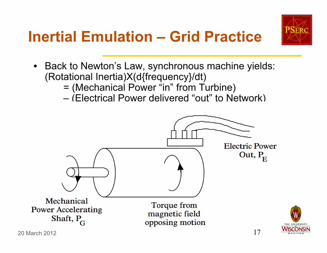
• Back to Newton’s Law, synchronous machine yields:(Rotational Inertia)X(d{frequency}/dt)
= (Mechanical Power “in” from Turbine)– (Electrical Power delivered “out” to Network)

20 March 2012 18
Inertial Emulation – Grid Practice
• Viewing Newton’s law as a power balance equation, theeffect of inertia is another power term.
KEY IDEA IN LITERATURE: To mimic the inertial effectin a non-synchronous, power electronically coupledrenewable generator. And looks easy: just need to adda controllable power term, proportional to time derivativeof frequency.

20 March 2012 19
Inertial Emulation – Critique
Seems reasonable - so what’s the criticism?Put on the hat of a control system design engineer.Observe that key measurement at any generating unit isits terminal frequency; a key commanded input is thepower desired from the unit.
• From this control design perspective, inertial emulationis nothing more than a derivative feedback control!
• Derivative feedback control is not bad, per se, but it isone piece of the simplest, most basic control design ideaany 3rd-year undergraduate learns (PID control). OK forsimple single-input/single-output systems.
20 March 2012 20
Inertial Emulation – Critique
• For large scale, multi-input/multi-output systems like thepower grid, derivative feedback seems, well…“unambitious.” It has well-known practical problems,chiefly poor high frequency noise/disturbance immunity.
• In applications for wind energy, inertial emulation needsfurther filtering to moderate drive train stress.
• So any practical control implemented based on inertialemulation will be far from the underlying ideal, due tobandwidth limits. Strong evidence suggests one coulddo much better if bandwidth limitation explicitly treated inthe control design process.
20 March 2012 21
Vision of Future ControlStrategies for Renewables
• From design perspective, renewable generators arecontrol “actuators,” taking commanded power change asan input, achieved electrical power change as an output.
• Previous discussion suggest that they have (at least)two constraints as actuators, that good design shouldoptimize within: (i) bandwidth limits; (ii) saturation limits.
• Moreover, their general transfer characteristics are quitedifferent from traditional synchronous machines.Applying traditional control strategies, while workable,will likely be far from optimal.

20 March 2012 22
Vision of Future ControlStrategies for Renewables
• Important enabler: new measurement and sensor technologies,most notably PMU’s.
• Traditional primary control of a generator relies on immediatelyavailable local measurement only – typically just local frequency.
• If only local frequency measurement is available, “tweaking” oftraditional control designs (e.g., inertial emulation) may be OK.
• However, if one assumes that even a very small number of remotePMU measurements are allowed to be used in control design, dooris open to dynamic state observation. With this come significantpotential improvements in renewables’ control performance.

20 March 2012 23
Vision of Future ControlStrategies for Renewables
• With added sensor information to “feed” control, long history ofdevelopments in control design offer several families of powerfuldesign methods, any one of which could be effective for enhancingrenewables’ grid contributions: H-infinity; Convex Optimzationmethods/LMIs, and/or Linear Quadratic (LQ) methods.
• As proof of concept, the work here presents a research case study,based largely on the LQ design methodology.
• Primary objective here is not to advocate one method, however.Key goal:Emphasize promise of new measurementtechnologies, coupled with optimal control methods,to allow renewables to be larger contributors to gridprimary and secondary active power control.

20 March 2012 24
Case Study:A Future ControlStrategy for Renewables
• Choice for case study here sought a plausible scenario in which ourproposed feedback control could be added to an already validatedmodel for renewable generation. This led us to focus on windgeneration, with the WECC Type-3 “generic” model.
• Consistent with earlier observations and engineering commonsense, WECC type-3 model shows relatively low bandwidth in theturbine’s controllable power response (i.e., one is not allowed tochange the mechanical shaft power too rapidly).
• To complement this, sought a second source of controllable powerwith broader bandwidth, but smaller MW saturation limits.Experimentally-validated Lithium Ion battery models are found in theliterature, so these selected as complementary control source(photovoltaics could also play this smaller/faster MW control role).
20 March 2012 25
Illustrative DesignMethod & Case
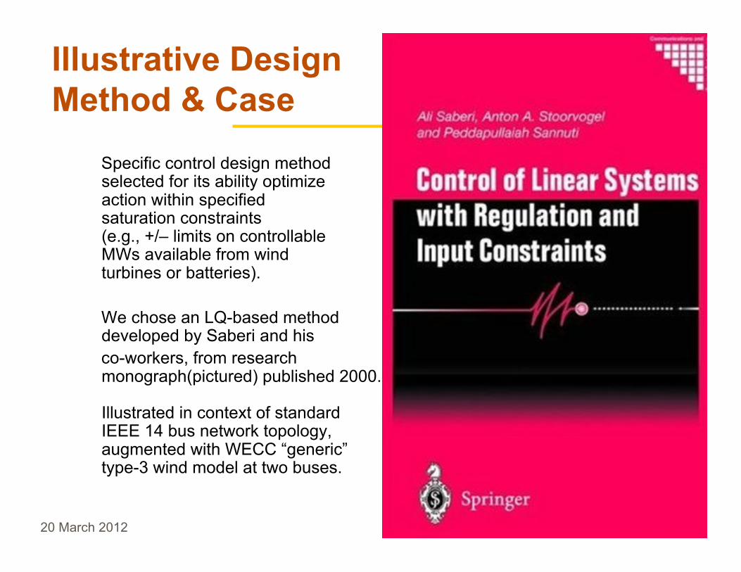
Specific control design methodselected for its ability optimizeaction within specifiedsaturation constraints(e.g., +/– limits on controllableMWs available from windturbines or batteries).
We chose an LQ-based methoddeveloped by Saberi and hisco-workers, from researchmonograph(pictured) published 2000.
Illustrated in context of standardIEEE 14 bus network topology,augmented with WECC “generic”type-3 wind model at two buses.

20 March 2012 26
Illustrative Design Example

20 March 2012 27
Illustrative Design Example
• This is very preliminary proof of concept – illustrate improved multi-variable performance with optimal control, as compared to behaviorwith standard WECC type-3 wind turbines and traditionalsynchronous generator controls alone.
• Admission of unfair contest in this example:Our design shows improvement both due to more sophisticatedestimation/control algorithm (main point here), AND due to ouraddition of small magnitude, broad bandwidth MW sources tocomplement the slower control response of wind machines.
• Here the small MW source is batteries; but could be fast control ofPV, or responsive load, or, reaching back to 1980 Cuttyhunkexample of introduction, a thyristor-controlled resistive load bank.The design method is agnostic as to source of power; key attributesare its MW response bandwidth and saturation limits.

20 March 2012 28
Illustrative Case Study:Performance Results
• Important to recognize a “trick” in the design method. It adopts anexplicit model for disturbances (i.e., fast-time scale variations in MWdemand and power output we must regulate against).
• In particular, a component of overall model here is an oscillatory,unforced linear subsystem with natural frequencies selected toapproximate spectral content of disturbances of interest.
• With disturbance model “built-in” (as opposed, say, to an externalstochastic characterization of disturbances), design method canoptimize control action within saturation limits with respect to anymodeled disturbance.
• Plots to follow will reflect this periodic nature of assumeddisturbances in observed steady state performance, both in thebase case and in our improved design.

20 March 2012 29
Illustrative Case Study: Base CasePerformance Results
• Below: system frequency vs. time with only “standard” WECC type-3 controls, and droop governor control on synchronous machines

20 March 2012 30
Illustrative Case Study: Base CasePerformance Results
• Below: local performance measure on wind machines – torquedifference between blade rotating mass and generator rotatingmass – indicative of drive-train stress in machine

20 March 2012 31
Illustrative Case Study: OptimalDesign Performance Results
• Below: system frequency vs. time with optimal control design,including fast control from batteries – ~100x improvement!

20 March 2012 32
Illustrative Case Study: OptimalDesign Performance Results
• “Side benefit” in a multivariable optimal design - can simultaneouslyimprove multiple performance measures. Magnitude of torquedifference/drive-train stress in machine is also reduced by ~2x.

20 March 2012 33
Illustrative Case Studies: Sourcesfor Added Detail
Brief slides unavoidably gloss over many technical details neededto judge these designs. For added detail, please consult the WhitePaper that accompanies this seminar, or the following:
• C. A. Baone and C. L. DeMarco, “Observer-based distributed control design tocoordinate wind generation and energy storage,” in Proceedings of 2010 IEEEConference on Innovative Smart Grid Technologies Europe, Gothenburg, Sweden,Oct. 2010.
• C. A. Baone and C. L. DeMarco, “From Each According to its Ability: Distributed GridRegulation With Bandwidth and Saturation Limits in Wind Generation and BatteryStorage,” to appear, IEEE Transactions on Control Systems Technology,IEEE Explore link:http://ieeexplore.ieee.org/xpls/abs_all.jsp?arnumber=6142123&tag=1
• C. A. Baone and C. L. DeMarco, “Distributed Control Design to Regulate GridFrequency and Reduce Drivetrain Stress in Wind Systems Using Battery Storage,” toappear, Proceedings of the 2012 American Control Conference, Montreal, CANADA,June 2012.

20 March 2012 34
Conclusions/Take Away PointsKey premises underlying this work:• Renewable generation, coupled to the grid through power electronic
interfaces, presents dynamic terminal characteristics very differentthan those of traditional turbine-driven synchronous machines.
• Dynamic differences become particularly relevant as renewablescontribute in grid primary & secondary frequency/power control.
• Added differences in architecture: much larger numbers ofindividual contributors, operating within narrower +/– MW limits.
• Properties above will likely also be seen in other emergingcontributors to “smart” grid control: new storage technologies andresponsive load.

20 March 2012 35
Conclusions/Take Away PointsConsequences for control design:• Dynamic observation of system state will become more important
as a component of feedback control. We should exploit controlopportunities enabled by wide bandwidth PMU measurements.
• To manage the diverse dynamic characteristics of renewables, andtheir inherently more distributed architecture, optimal-control-baseddesigns will become more important.
• As illustrative proof of concept, work here has examined a standardIEEE test system topology, augmented by WECC type-3 models forwind generators. In this (admittedly limited) example, displayed~100x improvement in frequency regulation against periodicdisturbances, while simultaneously reducing torque stress in windturbine drive train.

20 March 2012 36
Closing Analogy…Automotive Technology
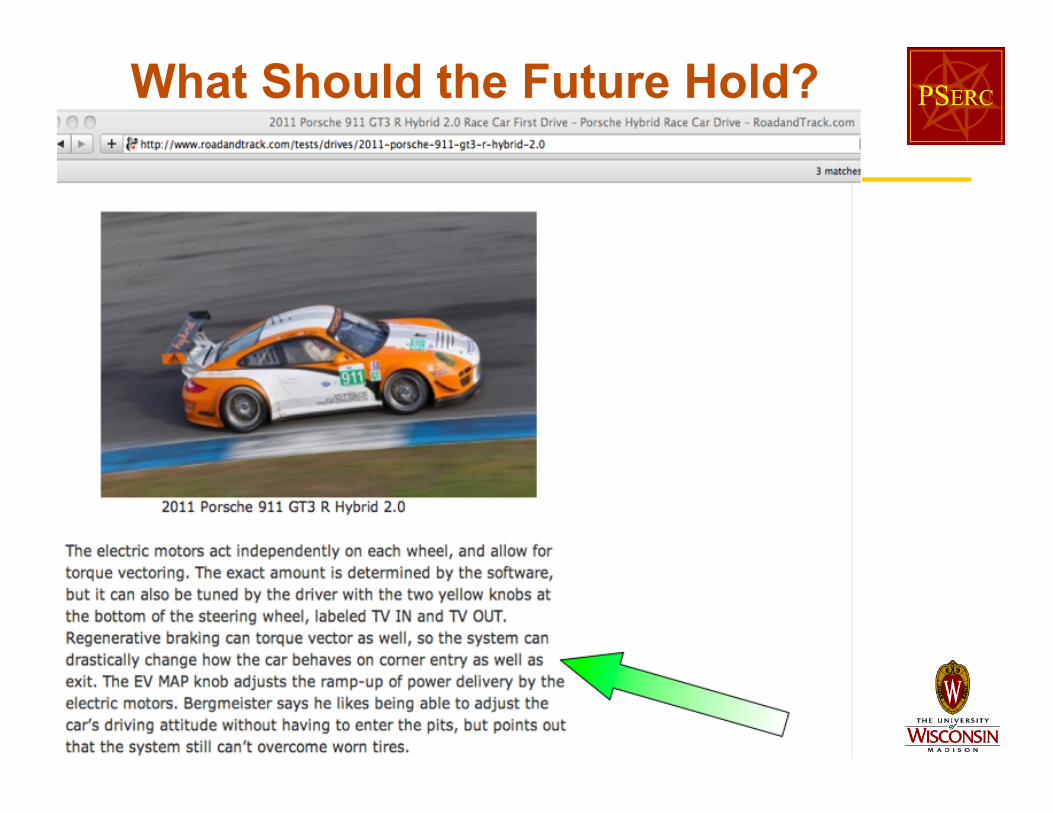
• As analogy to renewables as new class of MW actuators on grid…Consider a new class of “braking torque actuator” in automobiles.In contrast to mechanical frictional force of disk or drum brakes, wenow also have electromagnetic torque of regenerative braking.
• How should one use this new class of actuator? (as in our powergrid case, obvious it has very different dynamic characteristics!)
• First step – make this new class of braking actuator behave muchlike traditional technology. From pedal force as “command input,” toachieved braking torque at wheels as output, make brakes “feel”same as traditional disk brakes (observe analogy to inertial control).
• As a loyal Road & Track subscriber, the author can report this islargely what mainstream automotive vendors are doing today.With more imagination, what might we do better…
20 March 2012 37
What Should the Future Hold?