primary level and secondary level coordinated control of ... · primary level and secondary level...
TRANSCRIPT
Primary Level and Secondary Level Coordinated Control of Power Systems
E.A. ANDROULIDAKIS, A.T. ALEXANDRIDIS
Department of Electrical and Computer Engineering
University of Patras Rion 26500, Patras
GREECE
Abstract: - In this paper, two level coordinated control schemes for power systems are discussed. Coordination at the primary level is used to enhance transient stability and to assure voltage regulation. At the secondary level, the voltage set-point is corrected by taking into the account a coordinated control scheme that includes voltage and reactive power flow measurements at the pilot-nodes and the tie-line flows of a control area respectively. Key-Words: - Voltage control, transient stability, coordinated control, power systems. 1 Introduction In recent years, power systems operate under more stressed conditions and close to their stability limits. Due to recent blackouts the enhancement of power system performance has become a major concern [1]. In this frame, both the voltage control of the grid as well as the transient stability of the system is essential in order to improve the power system capabilities. New control schemes are proposed in all the levels of the hierarchical system of voltage and reactive power control. A great attention has been given also to the design of new advanced controllers at the primary level such as governors and power system stabilizers [2,3]. Three major kinds of power system stability are clearly classified in the short to mid-term time domain. Starting from the faster phenomenon, these are the transient (rotor angle) stability, voltage (reactive power) stability and frequency (small signal) stability. A basic task of a power system operation is to remain stable after any small or large disturbance or fault. To this end, more sophisticated control schemes have been proposed to satisfy this major requirement [3,4]. Coordinated control schemes combined with conventional or advanced control methods may be a global solution [5]. In this paper, we propose and discuss two different coordinated control schemes. First at the primary level, a complete coordinated scheme is discussed. At this level, a switching scheme is proposed that permits an immediate action of the power system stabilizer after a disturbance, following
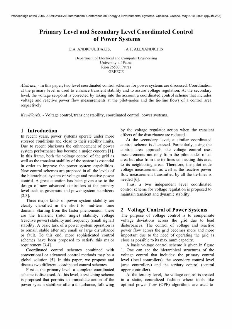
by the voltage regulator action when the transient effects of the disturbance are reduced. At the secondary level, a similar coordinated control scheme is discussed. Particularly, using the control area approach, the voltage control uses measurements not only from the pilot nodes of an area but also from the tie-lines connecting this area to its neighboring areas. Therefore, the pilot node voltage measurement as well as the reactive power flow measurement transmitted by all the tie-lines is needed [6]. Thus, a two independent level coordinated control scheme for voltage regulation is proposed to maintain transient and dynamic stability. 2 Voltage Control of Power Systems The purpose of voltage control is to compensate voltage deviations across the grid due to load disturbances. The control of voltage and reactive power flow across the grid becomes more and more important due to the need of operating the grid as close as possible to its maximum capacity. A basic voltage control scheme is given in figure 1. One can see the hierarchical structures of the voltage control that includes: the primary control level (local controllers), the secondary control level (area controllers) and the tertiary control (central upper controller). At the tertiary level, the voltage control is treated in a static, centralized fashion where tools like optimal power flow (OPF) algorithms are used to
Proceedings of the 2006 IASME/WSEAS International Conference on Energy & Environmental Systems, Chalkida, Greece, May 8-10, 2006 (pp249-253)
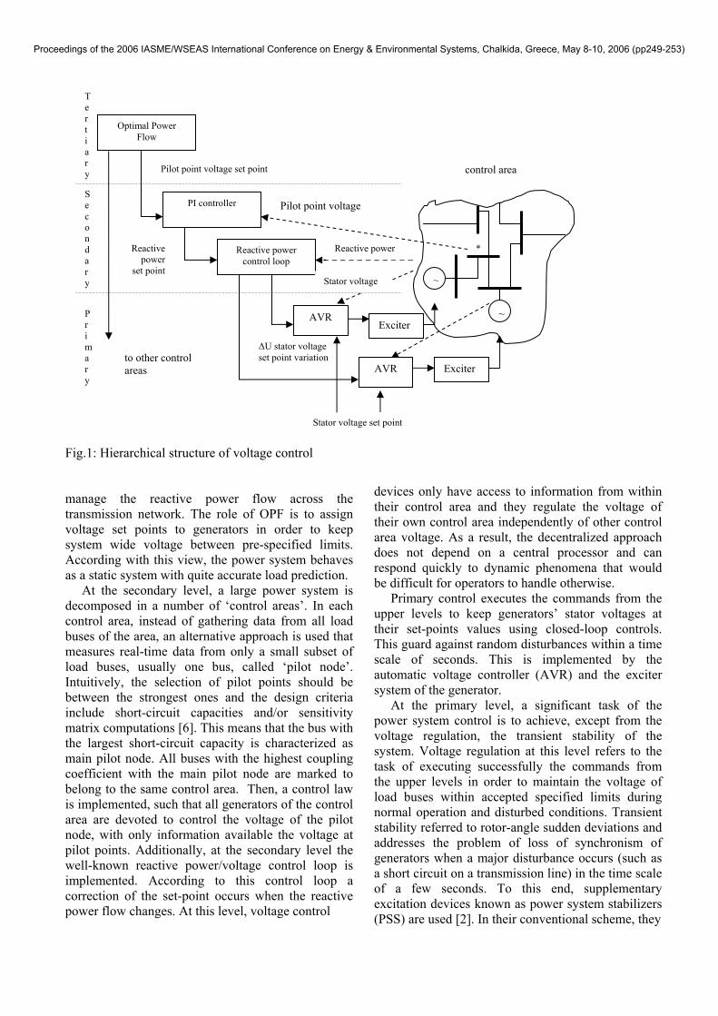
Fig.1: Hierarchical structure of voltage control manage the reactive power flow across the transmission network. The role of OPF is to assign voltage set points to generators in order to keep system wide voltage between pre-specified limits. According with this view, the power system behaves as a static system with quite accurate load prediction. At the secondary level, a large power system is decomposed in a number of ‘control areas’. In each control area, instead of gathering data from all load buses of the area, an alternative approach is used that measures real-time data from only a small subset of load buses, usually one bus, called ‘pilot node’. Intuitively, the selection of pilot points should be between the strongest ones and the design criteria include short-circuit capacities and/or sensitivity matrix computations [6]. This means that the bus with the largest short-circuit capacity is characterized as main pilot node. All buses with the highest coupling coefficient with the main pilot node are marked to belong to the same control area. Then, a control law is implemented, such that all generators of the control area are devoted to control the voltage of the pilot node, with only information available the voltage at pilot points. Additionally, at the secondary level the well-known reactive power/voltage control loop is implemented. According to this control loop a correction of the set-point occurs when the reactive power flow changes. At this level, voltage control
devices only have access to information from within their control area and they regulate the voltage of their own control area independently of other control area voltage. As a result, the decentralized approach does not depend on a central processor and can respond quickly to dynamic phenomena that would be difficult for operators to handle otherwise. Primary control executes the commands from the upper levels to keep generators’ stator voltages at their set-points values using closed-loop controls. This guard against random disturbances within a time scale of seconds. This is implemented by the automatic voltage controller (AVR) and the exciter system of the generator. At the primary level, a significant task of the power system control is to achieve, except from the voltage regulation, the transient stability of the system. Voltage regulation at this level refers to the task of executing successfully the commands from the upper levels in order to maintain the voltage of load buses within accepted specified limits during normal operation and disturbed conditions. Transient stability referred to rotor-angle sudden deviations and addresses the problem of loss of synchronism of generators when a major disturbance occurs (such as a short circuit on a transmission line) in the time scale of a few seconds. To this end, supplementary excitation devices known as power system stabilizers (PSS) are used [2]. In their conventional scheme, they
~
~
PI controller
AVRExciter
ExciterAVR
Reactive power control loop
Optimal Power Flow
Reactive power
∆U stator voltage set point variation
Reactive power
set point Stator voltage
Pilot point voltage
Stator voltage set point
*
Primary
Secondary
Tertiary Pilot point voltage set point
to other control areas
control area
Proceedings of the 2006 IASME/WSEAS International Conference on Energy & Environmental Systems, Chalkida, Greece, May 8-10, 2006 (pp249-253)
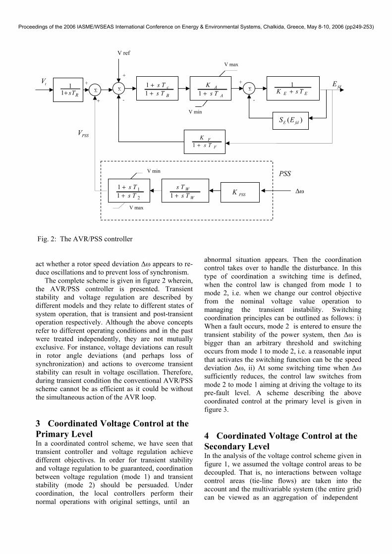
Fig. 2: The AVR/PSS controller act whether a rotor speed deviation ∆ω appears to re-duce oscillations and to prevent loss of synchronism. The complete scheme is given in figure 2 wherein, the AVR/PSS controller is presented. Transient stability and voltage regulation are described by different models and they relate to different states of system operation, that is transient and post-transient operation respectively. Although the above concepts refer to different operating conditions and in the past were treated independently, they are not mutually exclusive. For instance, voltage deviations can result in rotor angle deviations (and perhaps loss of synchronization) and actions to overcome transient stability can result in voltage oscillation. Therefore, during transient condition the conventional AVR/PSS scheme cannot be as efficient as it could be without the simultaneous action of the AVR loop. 3 Coordinated Voltage Control at the Primary Level In a coordinated control scheme, we have seen that transient controller and voltage regulation achieve different objectives. In order for transient stability and voltage regulation to be guaranteed, coordination between voltage regulation (mode 1) and transient stability (mode 2) should be persuaded. Under coordination, the local controllers perform their
normal operations with original settings, until an
bnormal situation appears. Then the coordination
Coordinated Voltage Control at the
ltage control scheme given in
can be viewed as an aggregation of independent
acontrol takes over to handle the disturbance. In this type of coordination a switching time is defined, when the control law is changed from mode 1 to mode 2, i.e. when we change our control objective from the nominal voltage value operation to managing the transient instability. Switching coordination principles can be outlined as follows: i) When a fault occurs, mode 2 is entered to ensure the transient stability of the power system, then ∆ω is bigger than an arbitrary threshold and switching occurs from mode 1 to mode 2, i.e. a reasonable input that activates the switching function can be the speed deviation ∆ω, ii) At some switching time when ∆ω sufficiently reduces, the control law switches from mode 2 to mode 1 aiming at driving the voltage to its pre-fault level. A scheme describing the above coordinated control at the primary level is given in figure 3. 4Secondary Level In the analysis of the vofigure 1, we assumed the voltage control areas to be decoupled. That is, no interactions between voltage control areas (tie-line flows) are taken into the account and the multivariable system (the entire grid)
1
2
11
s Ts T
++ PSSK1
W
W
s Ts T+
Σ1
E EK s T+ 1A
A
K11
c
B
s Ts T
++ s T+
( )E fdS E
Σ
V max
V min
V ref
Σ1
1 RsT+
PSSV
∆ω
tV
PSS V min
V max
1F
F
Ks T+
fdE +
- +
+
-
+
Proceedings of the 2006 IASME/WSEAS International Conference on Energy & Environmental Systems, Chalkida, Greece, May 8-10, 2006 (pp249-253)
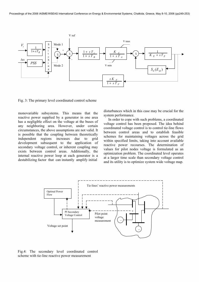
Fig. 3: The primary level coordinated control scheme
onovariable subsystems. This means that the active power supplied by a generator in one area
ig.4: The secondary level coordinated control scheme with tie-line reactive power measurement
isturbances which in this case may be crucial for the ystem performance.
In order to cope with such problems, a coordinated
ntrol is to control tie-line flows
mrehas a negligible effect on the voltage at the buses of any neighboring area. However, under certain circumstances, the above assumptions are not valid. It is possible that the coupling between theoretically independent regions increases due to grid development subsequent to the application of secondary voltage control, or inherent coupling may exists between control areas. Additionally, the internal reactive power loop at each generator is a destabilizing factor that can instantly amplify initial
F
ds
voltage control has been proposed. The idea behind coordinated voltage cobetween control areas and to establish feasible schemes for maintaining voltages across the grid within specified limits, taking into account available reactive power recourses. The determination of values for pilot nodes voltage is formulated as an optimization problem. The coordinated level operates at a larger time scale than secondary voltage control and its utility is to optimize system wide voltage map.
~
~
PI Secondary Voltage Control
Optimal Power Flow
*Pilot point voltage measurement
Tie-lines’ rea ve power measurements cti
Voltage set point
Σ1
E EK s T+ 1A
A
Ks T+
11
c
B
s Ts T
++
( )E fdS E
1F
F
s Ks T+
Σ
V max
V min
V ref
Σ
11 RsT+
SwtV
itching
PSS ∆ω
Mode 1
Mode 2
-
+
Proceedings of the 2006 IASME/WSEAS International Conference on Energy & Environmental Systems, Chalkida, Greece, May 8-10, 2006 (pp249-253)

This involves assigning voltage set points for the ilot nodes of secondary voltage control and
area a
Conclusions he primary level, power systems ectively coordinated with AVR
References: 1] E.A. Androulidakis, A.T. Alexandridis, H.E.
D.P. Agoris, Effects of power system
[2]rol for multimachine power
[3]age regulation for power
[4]xcitation, PSS,
[5] Dynamic performance of the
[6]atic voltage control of the
pchanging tie-line flows. Currently, coordinated control is not automated, but if it were, it would operate on a 15-minute basis or more. Assuming that all three level of control (primary, secondary, coordinated) are timely and geographically independent, we can conclude that interactions between different levels of control do not exist. In a fully decentralized scheme a distinct performance index is optimized for each controlto obt in set points for the controllers. During optimization for a control area, the information used from the rest of the system is the tie-line flows into the control area. Tie-line flows are measured and used in deriving optimal set points. Figure 4 shows this secondary level coordinated control scheme. 5 It is proposed that at tstabilizers can be effcontrollers to maintain transient stability and voltage regulation. Furthermore, at the secondary level, pilot-node voltage measurements as well as tie-lines’ power flows measurements can be simultaneously used in a coordinated scheme to achieve voltage regulation.
[Psillakis, deregulation on control design and on High-Voltage grid structure and performance, WSEAS Trans. on Circ. and Systems, Vol.4, No.9, 2005, pp. 1043-1051. H.E. Psillakis, A.T. Alexandridis, A new excitation contsystems I: Decentralized nonlinear adaptive control design and stability analysis, Int. Journal of Control, Automation & Systems, Vol.3, No.2, 2005, pp. 278-287. Yi Guo, D. J. Hill, Y. Wang,, Global transient stability and voltsystems, IEEE Transactions on Power Systems, Vol 16, No 4, 2001, pp. 678-688. J. S.K. Leung, D. J. Hill, Y. Ni Global power system control using generator eFACTS devices and capacitor switching, Electrical Power and Energy Systems, Vol.27, 2005, pp. 448-464. A. Berizzi, M.Merlo, P. Marannino, F. Zanellini, S. Corsi, M. Pozzi,,
hierarchical voltage regulation: the Italian EHV system case, 15th Int. Conf. PSCC, Liege, Section 30, Pap. 3, 2005. S. Corsi, M. Pozzi, C. Sabelli, A. Serrani, The coordinated automItalian transmission grid – Part I: Reasons of the choice and overview of the consolidated Hierarchical System, IEEE Trans. on Power Systems, Vol.19, No.4, 2004, pp. 1723-1732.
Proceedings of the 2006 IASME/WSEAS International Conference on Energy & Environmental Systems, Chalkida, Greece, May 8-10, 2006 (pp249-253)