primary sedimentation - irc :: home · 2014-03-09 · feed channels with a free discharge 37 10....
TRANSCRIPT
Manuals of British Practicein Water Pollution Control
Unit Processes
PRIMARYSEDIMENTATION
The Institute ofWater Pollution ControlLedson House, 53 London Road, ^ ' 9 8 o
Maidstone, Kent. ME16 8JH \\5&1980 u * ™«*

Primary sedimentation tanks at the Ringley Fold works of the North West Water Authority
Manuals of British Practicein Water Pollution Control bQl< 9
Unit Processes
PRIMARY SEDIMENTATION
First edition 1973Reprinted 1980
The Institute of .YA-Water Pollution Control
1973
THE INSTITUTE OF WATER POLLUTION CONTROL
President:
J. T. Calvert, C.B.E., M.A., F.I.C.E., F.R.I.C.
Editorial Sub-Committee:
H. A. Hawkes (Chairman)
V. H. Lewin (Secretary)
H. H. Stanbridge (Editor)
P. S. Ashman
P. Cotton
M. D. F. Haigh
C. P. James
C. E. Jones
K. Jones (Co-opted)
Price £3-75

PREFACE
In 1970 the Council of the Institute of Water Pollution Control discussed thequestion of the publication of definitive manuals on the subject of British Practicein Water Pollution Control and concluded that such publications would begenerally welcomed.
The Institute's publication An Introduction to Sewage Treatment willcontinue to serve as a general guide to the layman interested in the subject, whilstthe manuals will, it is hoped, cover the subject in sufficient depth to becomeaccepted as a reference source both to those already actively engaged in thisparticular field as well as to students seeking authoritative guidance whenpreparing for professional qualifications.
Throughout the manuals of unit processes of waste-water treatment it will beseen that there is often a variety of equipment available for any particular pur-pose, and different modes of operation are described. Wherever possible, anindication will be given of circumstances which favour the use of any particulartype of equipment or method of operation which past experience has shown to beadvantageous. The variable nature of sewages and sludges means, however, thatsuch an indication can usually only be given with qualifications.
Every effort has been made to ensure that the information given is as up-to-date as is practicable and, where possible, future trends and likely innovationsare discussed.
The preparation of this Manual has included a lot of work on the part of anumber of persons, and the Sub-Committee of the Institute's PublicationCommittee which has been responsible for its production wish to thank thosemembers of the Council of the Institute who have made comments andsuggestions for its improvement, and especially do they wish to thank thestaff' of the Water Research Centre, Stevenage Laboratory.
This Manual was first printed in 1973 and has been reviewed by the currentSub-Committee; except for Section 5.1 only minor amendments have beenmade to the original version.
— 5 —
ACKNOWLEDGMENTS
The Institute wishes to make grateful acknowledgment to the following forpermission to reproduce illustrations:
Mr. L. H. Thompson, Divisional Manager, Metropolitan Public Health Division,Thames Water Authority (Plate 8).
Messrs. J. D. & D. M. Watson (Figure 8).
Dr. T. H. Y.Tebbutt, Senior Lecturer, The University of Birmingham (Figure 6).
Mr. G. Ainsworth, Director of Scientific Services, North West Water Authority(Frontispiece).
Council for the Institution of Municipal Engineers (Figure 25).
The Controller, H.M. Stationery Office (Figures 5 and 21).
William E. Farrer Limited (Plates 1, 3, 4, 5 and 10).
Ames Crosta Babock (Plates 2, 6, and 9; Figure 18),
Simon-Hartley Limited (Plate 7; Figure 19).
Kent Instruments Limited (Plate 11).
Templewood Hawksley Activated Sludge Limited (Figures 12,13,14,20 and 23).
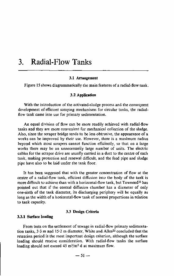
Whitehead and Poole Limited (Figure 15).
Dorr-Oliver Co. Ltd. (Figure 17).
Phox Instruments Limited (Plate 12).

CONTENTS
PREFACE 5
1. SEDIMENTATION: GENERAL CONSIDERATIONS 13
1.1 Purpose 131.2 Mechanism 141.3 Application 151.4 Factors Affecting Sedimentation 16
1.4.1 Composition of sewage 161.4.2 Preliminary treatment 161.4.3 Secondary sludges 171.4.4 Works liquors 181.4.5 Industrial waste waters 19
1.5 Sedimentation Tanks 201.5.1 Distribution of flow 211.5.2 Number 241.5.3 Types 251.5.4 Sludge collection and withdrawal 261.5.5 Design criteria 271.5.6 Design 301.5.7 Performance 301.5.8 Relative costs 32
2. HORIZONTAL-FLOW TANKS 33
2.1 Arrangement 332.2 Application 332.3 Design Criteria 33
2.3.1 Surface loading 332.3.2 Retention period 332.3.3 Dimensions 352.3.4 Weir overflow rate 35
2.4 Design 352.4.1 Inlet 352.4.2 Outlet 402.4.3 Floor 402.4.4 Collection of sludge 40
— 7 —

2.4.5 Sludge withdrawal 472.4.6 Scum collection and withdrawal 47
2.5 Performance , 48
3. RADIAL-FLOW TANKS 51
3.1 Arrangement 513.2 Application 513.3 Design Criteria 51
3.3.1 Surface loading 513.3.2 Retention period 533.3.3 Dimensions 533.3.4 Weir overflow rate 54
3.4 Design 543.4.1 Inlet • 543.4.2 Outlet 563.4.3 Floor 563.4.4 Collection of sludge 563.4.5 Sludge withdrawal 613.4.6 Scum collection and withdrawal 61
3.5 Performance 62
4. UPWARD-FLOW TANKS . 65
4.1 Arrangement 654.2 Application 654.3 Design Criteria 66
4.3.1 Upward velocity 664.3.2 Surface loading 664.3.3 Retention period 664.3.4 Dimensions 664.3.5 Weir overflow rate 67
4.4 Design ; 674.4.1 Inlet 674.4.2 Outlet 674.4.3 Lower portion of tank 674.4.4 Sludge withdrawal 684.4.5 Scum collection and withdrawal 684.4.6 Washout 68
4.5 Performance 68
5. OPERATION AND MAINTENANCE OF PRIMARY SEDIMENTATION TANKS . 69
5.1 Sludge Level Detection 695.2 Withdrawal of Sludge 70
— 8 —

5.2.1 Manually-desludged horizontal-flow tanks 715.2.2 Mechanically-desludged horizontal-flow tanks . . . 725.2.3 Radial-flow tanks 725.2.4 Upward-flow tanks 725.2.5 Automat i c control of sludge wi thdrawal 73
5.3 Opera t ing Difficulties 775.4 Periodical Empty ing of Mechanically-desludged Tanks . . . 785.5 Maintenance 78
6. PATTERN OF FLOW IN PRIMARY SEDIMENTATION TANKS 79
6.1 Methods of Investigation 796.1.1 Chemical tracers 796.1.2 Radioactive tracers 806.1.3 Float techniques 806.1.4 Lag in temperature change from inlet to outlet . . . . 81
6.2 Patterns of Flow 816.2.1 Horizontal-flow tanks 816.2.2 Radial-flow tanks 82
7. SPECIAL-PURPOSE SEDIMENTATION TANKS 83
7.1 Sedimentation/Flow Balancing Tanks 837.2 Sedimentation/Storm-sewage Tanks 847.3 Sedimentation/Sludge Thickening Tanks 857.4 Two-stage Sedimentation Tanks 85
8. AIDS TO SEDIMENTATION 87
8.1 Pre-aeration 878.2 Chemical Treatment 878.3 Mechanical Flocculation 88
9. PRODUCTS OF PRIMARY SEDIMENTATION 89
9.1 Settled Sewage 899.2 Sludge 89
9.2.1 Characteristics 899.2.2 Production 90
9.3 Scum 91
10. SEPTIC TANKS 93
10.1 Cesspools and Septic Tanks 9310.2 Arrangement 9310.3 Design Criteria 9410.4 Design 95
- 9 —

10.4.1 Inlet 9510.4.2 Outlet 9510.4.3 Floor 9510.4.4 Sludge withdrawal 9710.4.5 Scum collection 97
10.5 Operation 9710.6 Performance 9710.7 Sludge Production 98
REFERENCES 100
INDEX 104
PLATES
(Between pages 64 and 65)
1. Travelling-bridge scraper with vertical blade.2. Travelling-bridge scraper with trailing blade.3. Horizontal-flow tanks equipped with flight scrapers.
4. Inlet end of horizontal-flow tank equipped with buoyant flight scraper.
5. Outlet end of horizontal-flow tank equipped with flight scraper, showingtubular boom at end of travel and scum outlet.
6. Rotating half-bridge scraper with blades arranged in echelon.
7. Rotating half-bridge scraper with straight-blade sections.8. Rotating half-bridge scraper with blades arranged in echelon.9. Radial-flow tank, showing slotted scum outlet and scraper for vertical
wall.
10. Rotating half-bridge scraper, showing scum skimming blade with retain-ing pocket, hinged blade, ramp and scum trough.
11. Detector head of magnetic flow meter.
12. Example of an optical sludge level detector.
FIGURESPage
1. Tapering channel feeding series of horizontal-flow tanks . . . . 222. Distribution chamber serving four radial-flow tanks 223. Example of bad design of distribution chamber 234. Distribution chamber designed to provide equal distribution to
tanks of equal capacity but with varying lengths of feed pipe andlocated at various levels 24
— 10 —

5. Settling properties of suspended solids in samples of crude sewagefrom four sewage-treatment works 29
6. Relation between settleable solids and suspended solids in (a) crudesewage and (b) settled sewage 31
7. Main features of a manually-desludged horizontal-flow primarytank 34
8. Inlets to horizontal-flow tanks 369. Feed channels with a free discharge 37
10. Submerged entry inlets to horizontal-flow tanks 3811. Drowned, free-surface entry inlets to horizontal-flow tanks . . 3912. Trailing-blade scraper with a rack and pinion drive serving a
horizontal-flow tank with sludge hoppers 4213. Vertical-blade scraper serving two horizontal-flow tanks, with
cross collectors 4314. Flight scraper with three blades serving a horizontal-flow tank . . 45
15. Main features of a radial-flow primary tank 52
16. Radial-flow primary tank at Mogden Works: (a) before modifica-tion, (b) after modification 55
17. Radial-flow tank with fixed-bridge scraper 5718. Radial-flow tank with rotating half-bridge scraper 6019. Scum removal equipment using a ramp with a hinged scraper
blade 6220. Scum removal equipment using a tilting tray 6321. Main features of an upward-flow primary tank 65
22. Diagram of optical assembly of a photoelectric sludge-leveldetector 69
23. Relation between dry solids content and volume of sludge . . . 71
24. Rotork-actuated telescopic valve 7425. Arrangement for automatically stopping withdrawal of sludge
from a sedimentation tank 7526. Pattern of flow in a horizontal-flow tank at Beckton Works
determined by radioactive tracer 8227. Horizontal flow pattern in primary tank at Rotherham, de-
termined by two-float technique 8228. Two-compartment septic tank suitable for treating sewage from
up to 30 persons 9429. Two-compartment septic tank suitable for treating sewage from
over 30 persons 96
— 11 —

1. Sedimentation: General Considerations
1.1 Purpose
Sewage is complex and contains polluting matter in many forms. Inaddition to the dissolved impurities, it contains a heterogeneous dispersionof numerous substances, both organic and inorganic, in colloidal, pseudo-colloidal and simple suspension. Gross solid material and most of theinsoluble inorganic matter are removed by the preliminary processes ofscreening and grit removal but the remaining suspended matter, which ismainly organic and highly polluting, passes forward in the body of the liquid.
The purpose of sedimentation is to separate the sewage into two maincomponents, sludge and settled sewage, which by being treated separatelyare normally dealt with more efficiently and economically. Generally up to50 per cent of the total polluting load in the sewage is removed by sedimenta-tion. The secondary, or biological, treatment of sewage results in theproduction of further organic solid materials (secondary sludges) which aremore difficult than primary sludge to dewater, consequently any process thatcan reduce or minimize the production of secondary biological sludge is to befavoured.
Primary sedimentation is the process by which the velocity of the sewageis reduced below the point at which it can transport the suspended matter,so that much of this settles and can be removed as sludge.
Basically, the purpose of sedimentation is to remove the maximum amountof polluting matter, in the form of readily settleable solids, from the sewageas quickly and as economically as possible. However, this has beneficial sideeffects, which include:
(a) flocculation of the finely dispersed solids and adsorption of col-loidal and pseudo-colloidal matter on to the solids,
(b) equalization of the strength of the sewage prior to further treat-ment, and
(c) the provision of time to enable possible beneficial biologicalchanges to take place in the sewage1.
— 13 —

14 PRIMARY SEDIMENTATION
1.2 Mechanism
The settling velocity of particles of suspended matter depends on theirsize, shape and density. According to Stokes' Law, which holds for finegranular particles, their rate of settlement varies:
(a) as the square of the diameter of the particle,
(b) as the difference in density between the particle and that of thefluid in which it is suspended, and
(c) inversely as the viscosity of the fluid, which is dependent on itstemperature.
Hazen2 investigated the settlement of larger particles using quartz sandwith a specific gravity of 2-65 and the grains ranging in diameter from 0-1 to1 mm. He found that with such particles fluid friction rather than viscositycontrols the rate of settlement. There is therefore a transition stage duringwhich the viscosity becomes less important and the importance of fluidfriction increases. With granular particles this occurs as the diameter of theparticle reaches about 0-9 mm.
However, Hazen's investigation was carried out with granular particlessettling under quiescent conditions. In sewage treatment the conditions arevastly different. The particles vary widely in size, shape and density, they areflocculent in character and the sewage is moving. Also the sewage is subjectto currents caused by:
(a) dissipation of energy at the inlet,
(b) differences of density and temperature between the sewage enter-ing the tank and its contents (particularly when the incomingsewage contains a high concentration of suspended solids),
(c) wind effects,
(d) short-circuiting, and
(e) upward draw at the outlet.
Consequently there are considerable limitations on the application of Stokes'Law and the results of Hazen's investigation to the settlement of suspendedmatter in sewage.
The factors mentioned in the previous paragraph tend to affect settle-ment adversely, but there are others which assist settlement. Owing to thevarious currents the flocculent particles in sewage are continuously impingingon one another and as they settle at different velocities, with particles settling

SEDIMENTATION: GENERAL CONSIDERATIONS 15
at a faster rate overtaking those falling at a slower rate, an opportunity isafforded for them to coalesce and form larger particles the rate of settlementof which is even faster.
As particles settle, liquid is displaced and settlement is then impeded. Thestage is next reached when the downward movement of the particles startsto impede the upward flow of displaced liquid through the void channelsuntil, eventually, the throttling effect equals the effect of gravity and theparticles come to rest.
The size, shape and density of the particles of suspended matter in sewage,and therefore the efficiency of settlement, depend on a number of factors,such as:
(a) the system of sewerage,
(b) the age of the sewage, and
(c) the degree of fragmentation before settlement, due to pumpingand preliminary treatment.
Also, Stones1 has shown that biological changes take place during thepassage of sewage through a sedimentation tank, reducing its oxygen demandquite independently of the reduction due to the removal of suspended matter.
The settlement of sewage is therefore very complex and for this reason it isnot yet possible to design sedimentation tanks on a purely theoretical basis.
1.3 Application
Once the gross solids and grit have been removed from sewage, sedimenta-tion is generally considered to be the cheapest way of removing impuritypresent as suspended matter.
Solid matter not removed during sedimentation adds to the load on thebiological treatment plant and increases the amount of secondary sludge tobe dealt with. It has been suggested that with an activated-sludge plant awell settled sewage may not contain sufficient solid particles to act as nucleifor the floes of activated sludge but on a works producing such a sewage ithas been shown that this fear is unfounded3. With a biological filter plantan increase in the solids content of the settled sewage will increase thepossibility of the filters becoming blocked.
Secondary sludges are much more voluminous and more difficult to
16 PRIMARY SEDIMENTATION
dewater than primary sludge and an increase in the amount relative to that ofthe primary sludge will increase the difficulty of treating the sludge as awhole. Also secondary sludges are often returned to the incoming sewage forsettlement along with the sewage solids and the greater the amount returnedthe greater will be the load on the primary tanks.
It is therefore advisable that in the treatment of sewage, provision shouldbe made for removing solids by sedimentation to the greatest reasonableextent.
1.4 Factors Affecting Sedimentation
1.4.1 Composition of sewage
The sedimentation of domestic sewage is affected by the concentrationand character of the solids present in the sewage and by its content of syn-thetic detergents. Experiments carried out by the Water Pollution ResearchLaboratory4 showed that the amount of sludge produced was largely con-trolled by the hardness of the water supply; with a soft water the amount ofsludge which settled in a given time was reduced, but with a hard water theaddition of packaged detergent resulted in the formation of a considerablyincreased volume of sludge. It was found that the additional solid mattercontained calcium and phosphate, together with flocculated organic matterderived from the sewage, and it was concluded that the increased volume ofsludge was due to the "builders" present in the synthetic detergent.
1.4.2 Preliminary treatment
Sewerage system. With a separate system of sewerage less solid matterwill be diverted to the watercourse in wet weather than with a combinedsystem and the load on the sedimentation tanks will be greater; also if thesewers have been laid to slack falls they will not be cleansed in wet weather.Sewers should be laid to such a fall that the velocity is self-cleansing, at leastduring the daily period of peak flow in dry weather, otherwise the sewagewill be stale and may even be turning septic by the time it enters the sedi-mentation tanks. Deposits of grit and septic sludge will be scoured out anddischarged to the works when rainfall causes the flow to increase after aperiod of dry weather.
Pumping. The turbulence created during pumping, especially when thepumps are small, tends to disintegrate settleable solids and renders thesewage less amenable to sedimentation.
SEDIMENTATION: GENERAL CONSIDERATIONS 17
Screening. If screening is inefficient, or the screenings are disintegratedand returned to the sewage, or the sewage passes through comminutors,shredded rag will collect on underwater steelwork of scrapers or tend to"ball up" and cause blockages at tank inlets and in sludge pipelines, whilstthe amount of scum to be dealt with could be increased.
Grit removal. If grit removal is inefficient, and this may occur particularlyat high flows, grit will be deposited in slack areas on the floors of tanks, in themitres of sludge hoppers, or in sludge pipelines where it may cause a blockage.If it collects in the central hopper of a radial-flow or upward-flow tank themanual work involved in removal is dirty, arduous and time-consuming.
1.4.3 Secondary sludges
When biological-filter sludge or surplus activated sludge is returned to theprimary sedimentation tanks an additional load is imposed on them, depend-ing on the rate of return and solids content of the secondary sludge and therate of flow and solids content of the sewage during the period of return.
It has been demonstrated5 that when secondary sludge is returned con-tinuously to primary tanks the concentration of suspended solids (SS) inthe sewage may be increased by 50 to 100 mg/1, or roughly 10 to 20 per centof the initial concentration in the crude sewage. When secondary sludges arereturned intermittently the increase in the solids concentration over shortperiods is much higher. Thus, sludge from biological filters is often allowedto accumulate in horizontal-flow secondary tanks for periods of 24 h orlonger and when it is eventually returned to the works inlet the concentrationof SS in the sewage may be increased by as much as 2000 mg/1. Townend6
estimated that the return of surplus activated sludge to primary sedimentationtanks at the Mogden Works increased the concentration of SS in the crudesewage by about 120 mg/1.
Tests carried out by the Water Pollution Research Laboratory5 showedthat "the introduction of secondary sludges is likely to increase the con-centration of solids in the settled sewage but that this increase will probably befairly small".
Experiences with the return of surplus activated sludge have varied. At theMogden Works, Lockett7 found that sludge rose to the surface of the primarytanks when the concentration of nitrate N in the sewage after admixture withsurplus activated sludge was about 5 mg/1 but that no difficulty was experi-

18 PRIMARY SEDIMENTATION
enced when the concentration was 3 mg/1. At the Maple Lodge works8 thereturn of surplus activated sludge from a plant which was producing a highlynitrified effluent was discontinued after it was found that denitrifying bacteriain the sludge were multiplying in the primary tanks and causing denitrificationto take place in the secondary settlement tanks; when the practice wasdiscontinued denitrification ceased. At Oxford9 the practice was discontinuedwhen it was found that some of the activated sludge was passing through theprimary tanks and back to the aeration plant.
At the Hogsmill Valley works3, after it was found that activated sludgewas passing through the primary tanks the practice was adopted of returningthe surplus sludge at a steady rate throughout the night when the flow ofsewage was low and then withdrawing mixed sludge from the primary tanksearly the next morning before the activated sludge had had time to turnseptic. When, for a period, the surplus activated sludge was dealt withseparately10 there was no improvement in the quality of the settled sewageand difficulty was experienced with movement and withdrawal of the heaviersludge.
One great advantage of returning secondary sludge to the primary tanksis the reduction in volume which occurs. At the Mogden works6,4090 m3/d ofsurplus activated sludge was returned but the volume of mixed sludge with-drawn from the primary tanks averaged only 2045 m3/d. At the HogsmillValley works10 an average of 445 m3/d of surplus activated sludge wasreturned but the volume of mixed sludge withdrawn from the primary tanksaveraged only 327 m3/d, the activated sludge constituting 26-8 per cent of thison dry solids.
1.4.4 Works liquors
Works liquors which are often returned to the primary tanks include thecontents of storm tanks and of other tanks on the works when they are beingemptied, liquor separated from digested sludge in secondary digestion tanks,storage tanks or lagoons, liquor originating from sludge conditioning ordewatering processes, and wash water from tertiary treatment plants.
Such liquors are usually returned during the working day when the loadon the primary tanks is at a maximum, and as they are often pumped byautomatically-operated pumps, the return is intermittent.
The SS content of sludge liquors may vary widely, depending on themethod used for conditioning or dewatering and its efficiency. Liquorseparated from digested sludge may cause septicity in the primary tanks,
SEDIMENTATION: GENERAL CONSIDERATIONS 19
and gassing may still be occurring which will hinder the settlement of solids.Traces of chemicals from the coagulation of sludge may assist sedimentation.
The effect of works liquors on the efficiency of primary sedimentationtanks therefore depends on many factors, including the source of the liquorand the efficiency of the conditioning or dewatering process, the period overwhich the liquor is returned and the manner in which it is returned.
1.4.5 Industrial waste waters
Industrial wastes vary widely in composition and character, and theireffect on primary sedimentation will depend on local circumstances, such asthe degree of pretreatment of the waste before discharge into the public sewer,the efficiency of control over its discharge, and the degree of dilution withsewage and other industrial wastes prior to sedimentation.
The following constituents and characteristics of industrial wastes mayaffect primary sedimentation:
High rates of flow. Significant variations in rate of flow due to the inter-mittent discharge of large volumes of industrial waste, e.g. from the periodicemptying of vats, may cause a temporary reduction in sedimentation effi-ciency, depending on the size of the drainage area and of the sewage works.
High temperature. The discharge of a substantial volume of hot waste incontravention of the Public Health Act 1936 may raise the temperature ofthe sewage. The reduction in viscosity which ensues will improve sedi-mentation, but any improvement may be offset by the adverse effect of densitycurrents set up in the tank as a result of the difference in temperature betweenthe incoming sewage and that in the tank. A higher temperature will encouragebacterial activity and difficulty may be experienced due to rising sludgecaused by the liberation of gas.
Suspended solids. High concentrations of inorganic solids, e.g. fromcollieries and clay workings, can cause overloading of the grit removal plantat high flows and increase the proportion of grit in the sludge, thereby in-creasing the density of the sludge and making collection and removaldifficult. High concentrations of organic matter will increase the amount ofsludge to be dealt with and if readily putrescible, e.g. from slaughterhousesand the food industry, may cause septicity, rising sludge and odour nuisance.Fibrous solids will increase the bulk of the sludge, and the possibility ofblockages in pipelines and heat exchangers and the formation of scum.

20 PRIMARY SEDIMENTATION
Colloidal matter. Wastes containing an excessive amount of colloidalmatter, such as from tanning, fellmongering, food processing, wool washingand laundering, do not readily respond to sedimentation and may causedifficulty at a small works, especially when there are seasonal flushes, e.g. asfrom canneries. Blood and residues from poultry processing plants may alsocause trouble. The lactose in dairy wastes may ferment to form lactic acidon standing, giving rise to the coagulation of fats and proteins in the primarytanks and adding to the amount of sludge to be handled.
Metals. Wastes from plating and other metal working industries, especiallythose containing aluminium and iron salts, can flocculate colloidal matterand thereby increase sedimentation efficiency. However, the amount ofsludge is increased, due partly to their content of inorganic matter but moreso because such chemically-flocculated and precipitated sludges may con-solidate much more slowly than those which are less colloidal. Also, becauseof their toxicity, biological changes which take place during passage of sewagethrough the sedimentation tanks may be inhibited.
Ether extractable material. Industrial wastes containing fats or emulsifiedoils, e.g. from meat processing, oil refining, soap making, wool scouring andtanning, and even from large numbers of restaurants and canteens, can coatwalls of sedimentation tanks with a fatty deposit which, if not removed,decomposes to form lower fatty acids having an unpleasant odour. Thedeposit imposes an excessive load on tank cleaning equipment and the amountof scum will be increased, with increasing possibility of blockages of scumdraw-offs, pipelines and pumps. The grease content of the sludge will also beincreased.
pH value. When an industrial waste causes the pH value of the sewage torise above 10, e.g. due to the presence of lime or alkaline salts, hydrolysis ofurea to ammonia is inhibited. A low pH may have adverse effects, includingmetal salts passing into solution and being carried forward to the biologicaltreatment plant.
1.5 Sedimentation Tanks
Sedimentation tanks are normally designed to operate on a continuousflow basis and are either rectangular or circular in plan, with hoppers or atrough for the collection of sludge and power-driven scraper devices to movethe sludge gently across the floor to the outlet. Facilities are usually providedfor collecting and removing scum and floating debris.

SEDIMENTATION: GENERAL CONSIDERATIONS 21
1.5.1 Distribution of flow
When there are a number of tanks, equal distribution of the sewage toeach tank at all rates of flow is difficult to achieve, particularly if the site areaand head are restricted.
Unfortunately cut-waters tend to collect rag and paper, and unlessregularly attended to the division of flow soon becomes unequal. Also, thevelocity of the sewage during distribution must be self-cleansing, otherwisedeposition of solids will occur.
Even if the flow is equally divided the solids load might not be so. Whenpartial settlement has already taken place the concentration of solids near thefloor will be greater than near the surface, and if the flow changes directionsolids will tend to be carried to the outside of the bend by centrifugal force.Consequently, before division takes place there should be some degree ofmixing, and there should be a minimum length of channel upstream of thecut-water to ensure a uniform flow.
Horizontal-flow tanks may be fed from pipes or channels; radial-flowand upward-flow tanks are fed by pipes.
When distribution is to be effected by channels the flow may be dividedso that each tank is fed by a separate channel in which there is a penstockto control the flow and a measuring device, the penstock being adjusted togive equal distribution as shown by the flow indicator with which eachchannel is provided. The use of a flume or a magnetic flow meter for thispurpose involves little loss of head and it is self-cleansing.
Where space is limited, a tapering feed channel, common to all the tanks,may be used, with each tank fed through penstocks as shown in Fig. 1. Thechannel is designed to give a constant velocity throughout its length, and itwill be noted that the channel ends at the last penstock, thereby avoidinghaving a "dead" end in which grit and scum may collect. At Sheffield11, forexample, a transverse feed channel serving eight horizontal-flow tanks is4-25 m wide at the inlet end and tapers to 0-6 m wide, with each tank beingfed by two 0-6 m square electrically-actuated penstocks designed to functionas remote-controlled submerged orifices of variable cross-section.
However, disadvantages of this method of distribution are the possibilityof solids being deposited in the feed channel with scum being trapped at itsend, and that a greater proportion of the solids will enter the first tank thanthe others.
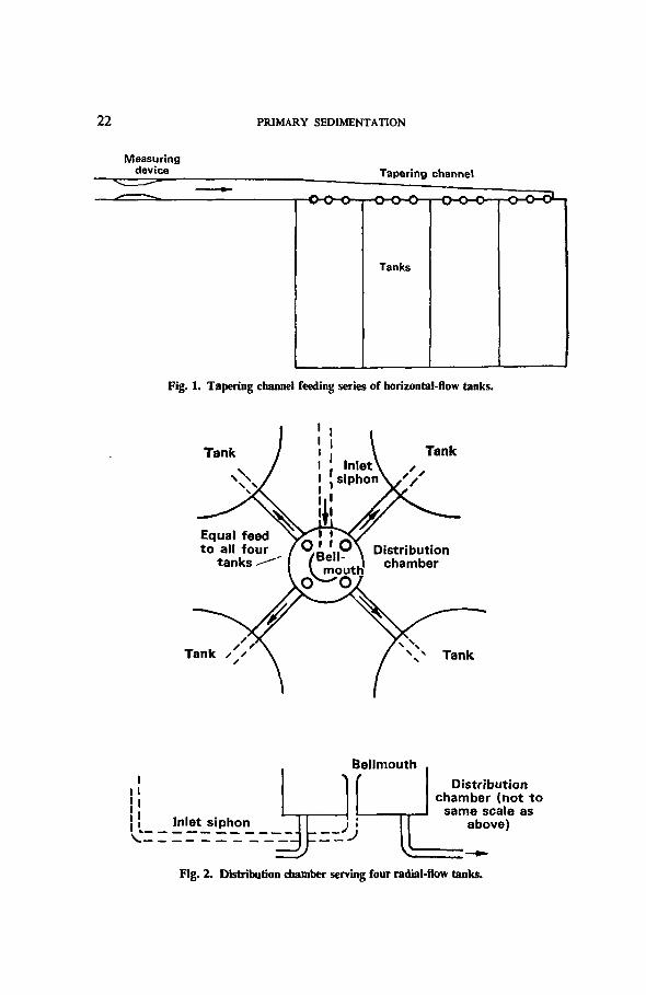
22 PRIMARY SEDIMENTATION
Measuringdevice Tapering channel
H O - O - O - T — O -
Tanks
Fig. 1. Tapering channel feeding series of horizontal-flow tanks.
Tank Tank
Equal feedto all four
tanks Bell-mouth'
CT-'O
Tank
iI
Inlet siphon
Bellmouth
-zfJ
Distributionchamber (not to
same scale asabove)
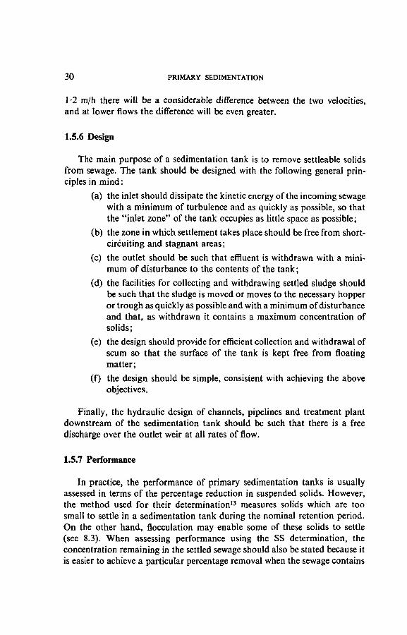
Fig. 2. Distribution chamber serving four radial-flow tanks.

SEDIMENTATION: GENERAL CONSIDERATIONS 23
Radial-flow or upward-flow tanks may be arranged symmetrically round aflow distribution chamber. One method is to discharge the sewage through avertical pipe with a bellmouth into a circular chamber as shown in Fig. 2. Thefeed pipes to the four tanks leave the chamber at floor level, and being equalin all respects (with all the tanks at the same level), equal distribution isachieved without the use of cut-waters.
A layout likely to give poor distribution is shown in Fig. 3 where, althoughthe feed arrangement to the individual tanks is equal in all respects, because ofthe directional velocity of the sewage discharging into the distribution chamber,two of the tanks are likely to receive a greater proportion of the sewage, andthe solids, than the other two tanks.
Identical feedsto all tanks
Fig. 3. Example of bad design of distribution chamber.
If the feed pipes are unavoidably unequal in length or size, a conicaldistribution chamber with weirs and partitions as shown in Fig. 4 may beused, the lengths of the individual weirs being proportional to the requiredflow.

24 PRIMARY SEDIMENTATION
Mainfeed pipe
Tank
Tank
Fig. 4. Distribution chamber designed to provide equal distribution to tanks of equal capacitybut with varying lengths of feed pipe and located at various levels.
With a small works, when the throat width of the flumes would be lessthan, say, 0-1 m and the diurnal variations in flow are large, a distributionchamber with weirs or weir penstocks may have to be used, although thisarrangement suffers from the disadvantage that solids are likely to be deposit-ed upstream of the weirs.
Whether channels with flumes or weirs are used for distributing the flow,the channel or weir must be sufficiently high above the outlet weirs of thetanks to give a free discharge at all rates of flow.
1.5.2 Number
The number of tanks should be such that one may be taken out of servicewithout interrupting or greatly affecting the sedimentation process. Con-

SEDIMENTATION: GENERAL CONSIDERATIONS 25
sequently, even with a small works there should be at least two tanks. With alarge works the number will depend on structural considerations, operatingconditions and the facilities available for removing and dealing with thesludge. In the case of circular tanks the larger the number the greater thetotal length of the overflow weirs and the smaller the overflow rate. Withupward-flow tanks, since there is an economic limit to their size, the numberwill depend upon the volume of sewage to be treated, with a minimum of twotanks.
1.5.3 Types
Horizontal-flow tanks. These are rectangular in plan, with the floorsloping towards a sludge draw-off at the inlet end. Although termed"horizontal-flow" tanks, the sewage usually enters at a lower level than thesill of the outlet weir and during passage through the tank the flow is affectedby eddies and currents, although its general direction is from one end of thetank to the other, with the heavier solids being deposited at the inlet end andprogressively lighter solids being deposited as the sewage flows from theinlet to the outlet.
Radial-flow tanks. These are circular in plan, with the floor sloping to acentral sump. The inlet is at the centre and since the level at which the sewageenters the body of the tank is usually much lower than that of the peripheralweir, the flow has an upward as well as a radial component. Also, during itspassage from the central inlet to the peripheral outlet the velocity of the sewageis constantly decreasing, reaching a minimum at the outlet weir. This destruc-tion of velocity renders the sewage susceptible to eddy currents.
Upward-flow tanks. These may be square or circular in plan and arebasically an inverted pyramid or cone, with the floor sloping sharply to acentral sump. The inlet is at the centre and the direction of movement of thesewage when it enters the body of the tank is downward. The sewage thenflows radially outward and upward towards a peripheral outlet weir. As thedistance below the surface of the zone in which the direction of flow changesfrom downward to outward and upward is relatively great compared with thehorizontal distance from the central stilling box to the peripheral outletweir, the direction of flow in the tank, although partly radial, is mainlyupward, hence the term "upward-flow" tank. With this type of tank, move-ment of the sewage is against the motion of the falling particles of solidmatter. Consequently a greater opportunity is afforded for particles toimpinge on one another and coalesce to form larger particles with consequentincreased efficiency of settlement and a higher quality effluent.

26 PRIMARY SEDIMENTATION
1.5.4 Sludge collection and withdrawal
Tanks may also be classified according to the method used for sludgecollection and withdrawal, as shown in Table 1.
TABLE 1. CLASSIFICATION OF PRIMARY SEDIMENTATION TANKSACCORDING TO THE METHOD USED FOR SLUDGE COLLECTION
AND WITHDRAWAL
Tank
Horizontal-flow tanks
Horizontal-flow tanks modified for cleaningby power-driven squeegee or rope-hauledscraper
Upward-flow tanks
Horizontal-flow tanks designed for "Imechanical collection . . .. >
Radial-flow tanks J
Method used for sludgecollection and withdrawal
Manual collection, removal by emptying tank.
Mechanical collection, removal by emptying tank.
Collection by settlement in deep hopper,withdrawal by pressure due to a differential head.
Mechanical collection, withdrawal by pressuredue to a differential head.
Mechanical collection, now normally used, has the following advantages:
(a) with sludge being withdrawn more frequently than with manualdesludging, less space is required for storing sludge, and as thesludge is withdrawn without the tank having to be taken out ofservice, the capacity required for settlement is reduced;
(b) less manpower is required for the desludging operation;
(c) the frequency and time of desludging can be keyed to the require-ments of other works operations such as the feeding of digestiontanks;
(d) with a horizontal-flow tank the operation of the scraper can beregulated to sweep that portion of the tank floor on which thebulk of the solids are deposited more frequently than otherportions of the floor;
(e) since the sludge stays in the tank for a shorter period of time thereis less tendency for it to turn septic, and as it is withdrawn underwater the possibility of odour nuisance is reduced;
(f) the desludging operation can be automatically controlled.
The disadvantages of mechanical collection are:
(a) the cost of the desludging equipment, and
(b) the cost of maintaining the equipment.

SEDIMENTATION: GENERAL CONSIDERATIONS 27
When primary sedimentation tanks are desludged mechanically it isadvisable to empty them at least once a year (see 5.4.).
Sludge pipelines. Owing to their liability to blockage, pipelines conveyingprimary sludge by gravity should be as short as possible, be of ample size andhave a minimum number of bends. They should be at least 200 mm andpreferably 250 mm in diameter and should have sufficient fall to promote aself-cleansing velocity of at least 1 -2 m/s. Manholes, which should be providedat each change of direction, should have a shaft which is not less than 1 mwide and the opening should have a minimum diameter of 0-6 m. Whencalculating friction losses in sludge pipelines account should be taken of thefact that such losses are 3 to 4 times those for water.
1.5.5 Design criteria
Maximum rate of flow. The design criteria for primary sedimentationtanks are based on the maximum flow to receive treatment. The method ofcalculating the maximum sewage flow is given in the manual on PreliminaryProcesses, and to this must be added the maximum rate of return of secondarysludge and works liquors, which should always be added to the sewagedownstream of the device for diverting storm-sewage.
Surface loading. This is expressed in terms of the maximum rate of flow tobe treated per day in m3 per m2 of tank surface, i.e.
c r i J- / i, •, JS Maximum flow (m3/d)Surface loading (m3/m2 d) = - — —
Tank surface area (m2)Hazen2 showed mathematically that surface loading is the most important
factor for design purposes. Consider a particle of suspended matter enteringa tank and falling downwards at a certain rate; whether or not the particlewill fall to the bottom of the tank before reaching the outlet will depend ontwo factors, viz. the distance through which it has to fall (the depth of thetank) and the length of time it stays in the tank (the retention period). If thedepth of the tank were doubled the period of retention would be doubled butso also would the distance through which the particle has to fall. If, on theother hand, the depth were halved the period of retention would also behalved. In both cases the chances of the particle falling to the floor beforereaching the end of the tank would be unaltered. If, however, the period ofretention were increased by increasing the surface area, i.e. increasing thelength or width of a rectangular tank or the diameter of a circular tank, thetime available for the particle to fall to the floor would be longer and thepossibility of this happening would therefore be increased.

28 PRIMARY SEDIMENTATION
Retention period. For design purposes, the nominal retention period isbased on the maximum rate of flow to be treated in m3/d and is given in hours,i.e.
_ , . . , , . . Total capacity of tanks (m3) „ .Retention period (h) = - - - — - x 24
Maximum rate of flow (m3/d)
A sedimentation tank may be regarded as having four zones:
(1) an inlet zone in which the kinetic energy of the incoming sewageis dissipated;
(2) the settling zone in which settlement takes place;
(3) the outlet zone, in which the effluent is collected before dischargeand in which disturbance may take place due to upward draw tothe outlet weir, and
(4) the sludge storage zone.
The settling zone represents the effective capacity of the tank and any reduc-tion in the sizes of the other three zones due to a more efficient inlet, a reduc-tion in the upward draw at the outlet or more frequent withdrawal of sludgeenables the retention period to be reduced.
The period of retention should be long enough to enable the requireddegree of settlement, flocculation and beneficial biological changes to takeplace, but anything beyond this will involve unnecessary capital expenditureand could lead to the sewage turning septic before it leaves the tank, withadverse effects on subsequent treatment and the possibility of odournuisance.
Results of tests carried out by the Water Pollution Research Laboratory5
on the settling properties of suspended solids in samples of crude sewage fromfour sewage-treatment works (Fig. 5) indicated that in each case "virtually allthe settleable material had been deposited within 2 h. The concentration ofvery slowly settling material after 2 h was greater the higher the initial con-centration of suspended solids". A nominal retention period of 2 h at maximumflow is now commonly used as a basis for the design of primary sedimenta-tion tanks which are desludged mechanically so that little storage space isneeded for sludge. However, a longer retention period is justified where thesewage has a higher SS content than usual or the solids settle less readily, orwhere the sewage has a high content of industrial waste which would other-wise cause shock loads on the biological treatment process.

SEDIMENTATION: GENERAL CONSIDERATIONS 29
1000,
KX) .ISOTIME (min)
Fig. 5. Settling properties of suspended solids in samples of crude sewage fromfour sewage-treatment works.
Weir overflow rate. This is expressed in terms of the maximum rate offlow to be treated in m3/d per metre total length of the outlet weirs, i.e.
Weir overflow rate (m3/m d) =Maximum flow (m3/d)
Total length of outlet weirs (m)
If the maximum rate of flow over a weir is less than 100 m3/m d, problemsmay occur because of surface tension and at low velocities the flow will notbe self-cleansing. For methods of increasing the weir overflow rate see 3.4.2.
If the weir overflow rate exceeds 450 m3/m d at maximum flow the velocityof the sewage as it approaches the weir will be excessive and sludge may bescoured out of the tank and scum drawn under the scum baffle. However,Table 3 shows that, in practice, reasonable efficiencies may be obtained athigher rates than this.
Upward velocity. In an upward-flow tank the particles of solid matter willbe falling against an upward flow of sewage, and consequently their rate oftravel will be retarded. With the particles falling at a rate varying from 3 to6 m/h and the upward velocity of the sewage at maximum flow being, say,
30 PRIMARY SEDIMENTATION
1 -2 m/h there will be a considerable difference between the two velocities,and at lower flows the difference will be even greater.
1.5.6 Design
The main purpose of a sedimentation tank is to remove settleable solidsfrom sewage. The tank should be designed with the following general prin-ciples in mind:
(a) the inlet should dissipate the kinetic energy of the incoming sewagewith a minimum of turbulence and as quickly as possible, so thatthe "inlet zone" of the tank occupies as little space as possible;
(b) the zone in which settlement takes place should be free from short-circuiting and stagnant areas;
(c) the outlet should be such that effluent is withdrawn with a mini-mum of disturbance to the contents of the tank;
(d) the facilities for collecting and withdrawing settled sludge shouldbe such that the sludge is moved or moves to the necessary hopperor trough as quickly as possible and with a minimum of disturbanceand that, as withdrawn it contains a maximum concentration ofsolids;
(e) the design should provide for efficient collection and withdrawal ofscum so that the surface of the tank is kept free from floatingmatter;
(f) the design should be simple, consistent with achieving the aboveobjectives.
Finally, the hydraulic design of channels, pipelines and treatment plantdownstream of the sedimentation tank should be such that there is a freedischarge over the outlet weir at all rates of flow.
1.5.7 Performance
In practice, the performance of primary sedimentation tanks is usuallyassessed in terms of the percentage reduction in suspended solids. However,the method used for their determination13 measures solids which are toosmall to settle in a sedimentation tank during the nominal retention period.On the other hand, flocculation may enable some of these solids to settle(see 8.3). When assessing performance using the SS determination, theconcentration remaining in the settled sewage should also be stated because itis easier to achieve a particular percentage removal when the sewage contains
SEDIMENTATION: GENERAL CONSIDERATIONS 31
a high concentration of solids than when the concentration is low. Theconcentration of SS remaining in the sewage is the important factor from thepoint of view of subsequent treatment.
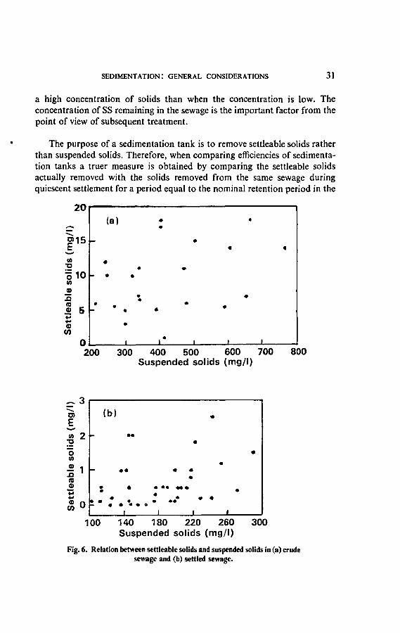
The purpose of a sedimentation tank is to remove settleable solids ratherthan suspended solids. Therefore, when comparing efficiencies of sedimenta-tion tanks a truer measure is obtained by comparing the settleable solidsactually removed with the solids removed from the same sewage duringquiescent settlement for a period equal to the nominal retention period in the
200 300 400 500 600 700Suspended solids (mg/l)
800
100 140 180 220 260Suspended solids (mg/l)
300
Fig. 6. Relation between settleable solids and suspended solids in (a) crudesewage and (b) settled sewage.

32 PRIMARY SEDIMENTATION
sedimentation tank or, as is usual in experimental work, during a period of 2 h.In experiments with the settlement of domestic sewage, Tebbutt12 found thatthere was no relationship between its content of settleable solids and the SSconcentration. His results are shown in Fig. 6. Other parameters for assessingtank performance include permanganate value14, BOD and COD.
1.5.8 Relative costs
Capital costs of different types of primary tank and of tanks of varioussizes constructed between 1956 and 1960, also costs of mechanical equipment,have been given by Calvert15, who emphasized the tremendous range in unitcosts. In general, the unit cost varied with the type of tank and its size and wasgoverned to a large extent by site conditions.
In 1969 Bradley and Isaac16 published the results of a survey of costs ofsewage treatment as at June 1967, which included graphs showing the relationbetween total capacity and capital cost per unit volume treated for differenttypes of primary tank. These form the basis of Table 2, which shows thatwhen the total capacity is 500 m3, upward-flow tanks are cheaper in capitalcost than either horizontal-flow tanks or radial-flow tanks—and this probablyholds true for tanks of smaller capacity. When the total capacity exceeds500 m3 there is little difference between the capital cost of horizontal-flowtanks and that of radial-flow tanks, and site conditions may be the decidingfactor.
TABLE 2. COMPARATIVE CAPITAL COSTS AT JUNE 1967 OFDIFFERENT TYPES OF PRIMARY SEDIMENTATION TANK*
Totalcapacity
(m»)
200
300
400
500
1000
1500
1750
2000
Total capital cost (£/m")
Horizontal-flowtanks
30
27
24
23
22
Radial-flowtanks
29
24
22
21
20
Upward-flowtanks
38
29
24
20
* Based on graphs in "The Cost of Sewage Treatment", by R. M. Bradley andP. C. G. Isaac. Wat.Pollut.Control. 68. 1969. (4). 368-402.

2. Horizontal-Flow Tanks
2.1 Arrangement
Figure 7 shows diagrammatically the main features of a manually-desludged horizontal-flow tank.
2.2 Application
For many years, horizontal-flow tanks were the type most often used forprimary sedimentation, but with the development of lighter scraping mech-anisms and the introduction of the concept of frequent withdrawal of sludge,radial-flow tanks came into use as an alternative.
Horizontal-flow tanks are economical in the use of land and, with theshorter feed pipes, less head is required. With a series of tanks, one divisionwall serves two units and one scraper can be made to serve more than onetank, also the feed and effluent channels are common to all the tanks and thesludge pipelines are shorter, more readily accessible and less liable to blockage.Another factor in favour of horizontal-flow tanks is that an operating gallerycan be incorporated in the design, housing the various services and permittingthe withdrawal of sludge to be supervised under cover.
2.3 Design Criteria
2.3.1 Surface loadingThis is usually about 30 m3/m2 d at maximum flow but may be as high as
45 m3/m2 d if the design maximum exceeds 3 DWF.
2.3.2 Retention periodIf the tanks are desludged mechanically the retention period should be at
least 2 h, based on the maximum sewage flow plus returned liquors.
If the tanks are desludged manually, appropriate provision must be madefor storing sludge and for ensuring that the increased rate of flow caused bythe withdrawal of one tank from service for desludging will not result in anunacceptable increase in the concentration of solids in the effluent from theother tanks.
- 33 —

Fig. 7. Main features of a manually-desludged horizontal-flow primary tank.
A, Feed pipe; B, feed channel; C, inlet weir; D, baffle plate; E, sludge channel; F, sludgepenstock; G, top water level; H, freeboard; I, floating-arm supernatant water draw-off;
J, scum baffle; K, outlet weir; L, effluent channel; M, floor.
8
I

HORIZONTAL-FLOW TANKS 35
2.3.3 Dimensions
Depth. Given the surface loading and the retention period, the depthmay be calculated. However, to avoid scouring of deposited sludge and sothat sludge disturbed by the motion of the scraper may not rise into the streamof sewage passing through the tank, with small tanks the depth from waterlevel should not be less than 1 -5 m at the outlet end. Large tanks may be up to3 m deep at the outlet end. The coping should be at least 0*3 m above waterlevel to prevent sewage and scum from being blown over it by high winds.
Length and width. The total area of the tank surface may be calculatedfrom the maximum rate of flow and the surface loading. The length is muchmore important than the width. Holroyd17 found that the settling velocity offloes falling in glass cylinders full of sewage ranged from 0-83 to 1-67 mm/s,and horizontal velocities of sewage flowing through rectangular tanks of0-005-0-015 m/s have been given by different authors. With a velocity of0-01 m/s the sewage would travel a distance of 72 m in 2 h and floes settling at,say, 0-83 mm/s would reach the floor of a tank 3 m deep about half way alongits length. However, as shown in Fig. 26 (page 82), the pattern of movementof sewage in a horizontal-flow tank is very complex, consequently the lengthcannot be calculated on a theoretical basis. For small tanks the ratio of widthto length is usually within the range of 1:2 to 1:4. With larger works the tanksmay be up to 100 m long, with the width of individual tanks being governed bythe number required and the limitations of the scraping mechanism.
2.3.4 Weir overflow rate
The weir overflow rate is determined by the maximum rate of flow and thetotal length of the outlet weirs. The maximum value should not exceed450 m3/m d and 300 m3/m d is preferable, although Table 3 shows that, inpractice, reasonable efficiencies are obtained at higher rates.
2.4 Design2.4.1 Inlet
In the distribution system serving the tanks the sewage should have avelocity of at least 0-3 m/s, otherwise solids will be deposited in the channels orpipelines. At the inlet to the tank the velocity should be reduced to about0-005 m/s and the design must provide for this to take place without creatingundue turbulence. Also, whereas the combined width of the inlet penstockswill probably be only 6 per cent of the tank's width, the design should aim atdistributing the flow uniformly over the full width of the tank, and to do thisover a flow range of up to 6 to 1.

36 PRIMARY SEDIMENTATION
FIRST MODIFICATION SECOND MODIFICATION
(a) Mogden Sewage Works, 1931 : Secondary sedi-mentation tanks. Length/width ratio 1-38 to 1 ;average water depth, 12 ft.
INLET 2-lnltts per 57ft.wide tank
(b) Ryemeads Sewage Works, 1951. Length/widthratio 2-95 to 1 ; average water depth 11-83 ft.
2 - I n l e t s per 56 ft :wide tank
(c) Wanlip Sewage Works, 1960. Length/width ratio3-32 to 1 ; average water depth 11-19 ft.
Fig. 8. Inlets to horizontal-How tanks.

HORIZONTAL-FLOW TANKS 37
In addition to dissipating the kinetic energy and promoting a uniformdistribution of the flow, the design of the inlet should be as simple as practic-able, with the minimum of surfaces on which grease and fats can collect, or oforifices which are liable to blockage. Vertical eddies may be destroyed by theuse of baffles with vertical slots and the depth of flow at the inlet should be asgreat as possible to provide adequate density mixing (see Fig. 8), consistentwith not interfering with the deposition of solids in the sludge hoppers ortrough. Hamlin and March18 found from experiments with a full-scalehorizontal-flow tank at Coleshill works that density currents tended to formwith low velocities in the inlet zone and that a high velocity at the inlet tendedto promote mixing and inhibit density currents. The smaller the tank the moreimportant the inlet design.
T.w.l.
Feedchannel
T.w.l.
Tank
Feedchannel
T.w.l.
Tank
Fig. 9. Feed channels with a free discharge.
The feed channel may receive sewage through openings controlled bypenstocks which can be closed when it is necessary to isolate the tank, oradjusted to control the flow into the tank. An alternative design is for thechannel to receive sewage through a pipe or pipes which should preferablydischarge in an upward direction, with the floor of the channel falling towardsthe inlet or inlets to maintain self-cleansing conditions.

38 PRIMARY SEDIMENTATION
The feed channel may have a free discharge or be drowned. With a freedischarge (see Fig. 9) the water level in the channel is independent of that inthe tank but such an arrangement is wasteful of head, promotes a high inletvelocity and may cause a submerged "waterfall" effect due to the directionalvelocity of the incoming sewage and to density effects. When the feed channelis drowned the connection between the channel and the body of the tank mayalso be drowned, or they may have a common water surface. With the sub-merged entry inlets shown in Fig. 10 the water level in the feed channel iscontrolled by the level of the outlet weir. Solids may therefore be deposited inthe channel, particularly at low flows, and scum may collect in it. However,satisfactory distribution of flow between a number of tanks is obtained if theiroutlet weirs are all at the same level.
fl U T.w.l.
Inlet i Ichannel 11
t
Penstockwith free
surface inlet
Slottedbaffle
Tank
T.w.l.
Inletchannelfl Submerged
weir Tank
Fig. 10. Submerged entry inlets to horizontal-flow tanks.

HORIZONTAL-FLOW TANKS 39
Drowned, free-surface entry inlets as shown in Fig. 11 are an improvementover submerged entry inlets because there is unlikely to be a build up of scumin the feed channel. Distribution of flow is again controlled by the outletweirs of the tanks and deposition of solids can occur at low flows, particularlywith the submerged outlet type of inlet. Also if the submergence of the weir isinsufficient, currents can be set up. At the Beckton works19 it was found thatwhen the degree of submergence was increased so that the depth of sewageflowing over the weir was 200 mm instead of 50 mm the pattern of movementin the tanks was greatly improved. In other cases depths of submergence ofbetween 400 mm and 900 mm have been used.
Channel iT.w.l.
Sluicevalve
1 Slotted• baffleii
Tank
Channel
Submergedpenstock
T.w.l.
Slottedbaffle Tank
Fig. 11. Drowned, free-surface entry inlets to horizontal-flow tanks.
Figure 8, from a paper by Oakley20, shows how the design of inlets forhorizontal-flow tanks has been improved. In (a) the sill of the weir wasprogressively lowered, from being at the same level as that of the outlet weirto being deeply submerged. In (b) and (c) improvements were made to themethod of admitting the sewage, to the design of the inlet baffle and to theshape of the wall under the inlet. However, Townend21 criticized (b) and (c)on the grounds that the divergent splay of the inlet was so far down the wallthat a descending current could interfere with delivery of sludge into the hoppers.

4 0 PRIMARY SEDIMENTATION
For tanks at Sheffield, Holroyd11 used a baffle chamber having 14 verticalslots 0-23 m wide and 1 -83 m long in a tank 22-9 m wide, and this was followedby a hydraulic diffusion grid extending across the full width of the tank. Thegrid was 2-44 m deep and was constructed of 100-mm pitch fibre pipes setvertically at 0-20 m centres.
On the other hand, White and Allos22 concluded as a result of experimentsthat refinements in inlet design were unlikely to produce substantial improve-ments in settlement.
2.4.2 OutletThe outlet is usually a weir across the full width of the tank, protected by a
scum baffle and discharging into a channel. An adjustable metal weir plateshould preferably be used so that it can be accurately set along its length andlevel with the outlet weirs of other tanks. Sometimes a double-edged trough seta short distance in front of the end wall is used, connected by pipes to theeffluent channel; by reducing the overflow rate there is less likelihood ofscouring sludge from the tank.
In a few cases where the sewage contains industrial wastes, to equalize thestrength of the settled sewage the outlet weir is carried part way along eachside of the tank as well as across the end so that sewage is withdrawn from thetank after varying periods of retention.
2.43 FloorOn small works which might have manually-desludged tanks the slope of
the floor should be such that the sludge can be readily moved by squeegeesand yet not so steep that workmen are liable to slip when cleaning the tank.Slopes ranging from 1 in 200 to 1 in 20 have been used, with 1 in 40 being themost usual. To facilitate cleaning, the floor has sometimes been given a crossfall of 1 in 40 to a central channel running the length of the tank and falling1 in 100 to a sludge sump at the inlet end.
With mechanically-desludged tanks the floor should have a fall of at least1 in 200 to sludge hoppers or a trough at the inlet end. In some cases the anglebetween the walls and the floor is chamfered.
2.4.4 Collection of sludgeManually de-sludged tanks. In a manually-cleaned tank there is a floating-
arm draw-off or telescopic valve through which supernatant water is with-drawn before the sludge is pushed manually by means of squeegees to thesludge outlet (see 5.2.1).

HORIZONTAL-FLOW TANKS 41
Mechanically-desludged tanks. Mechanical scrapers used in horizontal-flow tanks for sweeping sludge to the outlet or outlets are of two main types:
(a) travelling-bridge scrapers, and
(b) flight scrapers.
Travelling-bridge scrapers. These consist essentially of a power-drivenbridge spanning the tank from which is suspended either a vertical (Plate 1) ora trailing (Plate 2) blade. The bridge traverses the tank on rails, the bladebeing lowered when sweeping sludge to hoppers or a trough at the inlet endof the tank and raised for the return journey. The blade has a replaceable edgeof synthetic rubber or similar material, whilst its usual speed of travel is about1-2 m/min when sweeping and about 2-4 m/min when on the return journey,the return speed depending on the drive. The bridge is driven by an electricmotor and may be rope-hauled, with polyurethane tyres, or have a rack andpinion drive, or it may have a traction drive on rails. The rack and pinion drivehas the advantage over a traction drive in that the possibility of cross-windingor crabbing is eliminated and control over movement of the bridge by anintegrator (or the number of revolutions of the driving wheel) is simplified.
With the rack and pinion and traction drives the blade is hoisted by anelectric motor, power being supplied by a cable using a spring-reeled orpositively wound drum mounted on the bridge, whilst movement of the bridgeis controlled by limit switches at each end of the tank or by an integrator.With the rope-hauled bridge the blade is raised and lowered by actuatingramps. When ramps are used in conjunction with a traction drive this involvescontrol by complicated interlocking limit switches. Fig. 12 shows a trailing-blade scraper with a rack and pinion drive sweeping the sludge to hoppers.
When withdrawal of sludge is carefully controlled, hoppers produce athicker sludge than a trough, but they are more costly to construct and wherea single cross-concentrator directs the sludge and scum to one chamberserving two tanks there is only one sludge outlet for every pair of tanksinstead of a number of outlets.
Fig. 13 shows a vertical-blade scraper with cross collectors serving twotanks.
With travelling-bridge scrapers there should be a footpath between pairsof tanks to provide access to the bridge if movement is interrupted when thescraper is part way along the tank.


Fig. 13. Vertical-blade scraper serving two horizontal-flow tanks, with cross collectors.
1, Scraper main beam; 2, scraper main drive; 3, end carriage; 4, control panel; 5, drive rail; 6, idler rail; 7, sludge blade; 8, scum blade;9, hoist drive; 10, hoist roller guides; 11, cable drum; 12, concentrator; 13, concentrator guide track; 14, concentrator sludge blade;15, concentrator scum blade; 16, concentrator drive motor; 17, scum baffle; 18, concentrator control station; 19, sludge draw-off chamber;
20, sludge sump; 21, scum draw-off chamber; 22, hydrostatic valve.
INO
i

44 PRIMARY SEDIMENTATION
Travelling-bridge scrapers may be single span or one machine may spanseveral tanks, or a single-span scraper may be used on more than one tank, anelectrically-driven transporter travelling on a transverse track being used totransfer the machine from one tank to another. Alternatively, the tanks maybe arranged in two rows, with the inlet ends of one set of tanks backing on tothe outlet ends of the other set so that one scraper can serve two tanks in linewith each other. Yet another arrangement is for the inlet ends of both sets oftanks to be in the middle with the operating gallery in between. In some casesprimary sedimentation tanks and storm tanks have been combined in one ofthese ways.
An advantage of travelling-bridge scrapers is that they can be auto-matically controlled to sweep tanks in any desired sequence of operationalmovements. At the Mogden works23, for example, scrapers serving 64 mlong second-stage primary tanks start by sweeping one third of the floorlength, where most of the sludge is deposited, then two thirds and finally thecomplete length, in succession, at the end of which a period of rest for up to4 h is allowed.
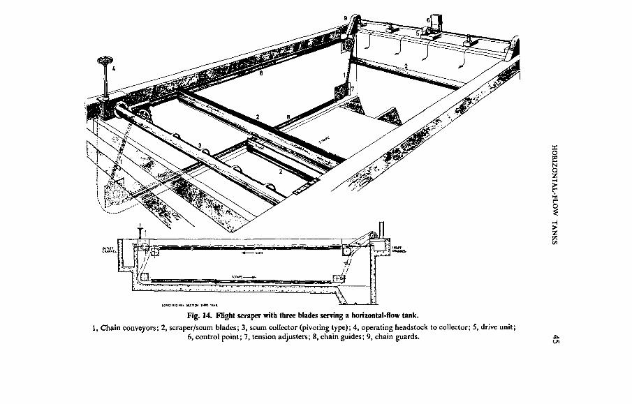
Flight scrapers. With this type of scraper (Plate 3) the blades or "buoyantflights" span the tank and are attached to endless chains, one on each side ofthe tank. The chains run on sprocket wheels supported from the side walls ofthe tank, two near the floor and two just below the water surface, and thechains are driven from a common shaft by an electric motor mounted on thetank wall at the inlet end. The flights move along the tank floor at about0-6 m/min and sweep the sludge into hoppers, or sometimes a trough with achain flight cross conveyor or blade concentrators at the inlet end. Theythen return along the surface, sweeping ihe scum to the outlet end of the tank.When there are three blades these are equally spaced, as shown in Fig. 14.With the "buoyant flight" scraper (Plates 4 and 5) the blade is attached to atubular boom which, when submerged, makes it slightly buoyant, therebyreducing the load on the chains and on the guide rails in which they slide butstill exerting sufficient pressure on the floor to move the sludge.
Since there is a separate scraper for each tank, only one tank is affectedif a breakdown occurs, and owing to their simplicity the scrapers can beoperated by unskilled labour. However, the whole of the equipment issubmerged so it is essential that the chains and sprockets shall be fullycorrosion resistant and receive regular maintenance. Also, as scum is with-drawn at the outlet end of the tank, difficulty may be experienced in deliveringit into the sludge main.
§Ni
it
T
Fig. 14. Flight scraper with three blades serving a horizontal-flow tank.
1, Chain conveyors; 2, scraper/scum blades; 3, scum collector (pivoting type); 4, operating headstock to collector; 5, drive unit;6, control point; 7, tension adjusters; 8, chain guides; 9, chain guards.

46 PRIMARY SEDIMENTATION
A modified form of flight scraper with a single blade, suitable for tanks upto 9 m wide, uses a large-diameter light-alloy tube from which a trailing bladeis suspended. The tube is supported by and receives its motion from twoendless chains running in guides mounted on the tank copings. As it followsthe chain path the blade sweeps the floor to the sludge hopper and is thenlifted clear for the return journey. The chains are driven by an electic motorthrough a cross shaft and chain reduction units, and control is by push-button. This scraper has the advantage that the chains are above water,simplifying maintenance.
Modification of tanks designed for manual desludging. On a large workswhere horizontal-flow tanks were not designed for mechanical desludging andit has not been considered feasible to modify them to enable a conventionalscraper to be installed, a considerable economy in manpower can result frommodification of the tanks to enable specially designed scrapers to be used.Modification has usually involved removing cross walls and levelling the flooror giving it a slope of perhaps 1 in 200 towards the sludge outlet at the inletend of the tank. A power-driven squeegee, a rope-hauled scraper blade or atravelling-bridge scraper with a vertical blade may then be used.
Power-driven squeegees. A scraper blade is attached to a lightweightmachine or a light tractor or bulldozer which is lowered into the tank by acrane or runs into the tank down a specially constructed ramp.
Rope-hauled scraper blade. This consists of a steel-lattice frame fitted witha steel and rubber blade which spans the full width of the tank. The frame ismounted on two bogies and is hinged to allow the blade to be lowered forforward movement and lifted for reverse. The machine runs on two railsfixed to the tank floor and is hauled by nylon ropes connected to a winchmounted at one end of the tank and driven by an electric motor.
Travelling-bridge scraper with vertical blade. A travelling-bridge scraperif of the vertical-blade type may be used in conjunction with one or two crossconveyors. When the main scraper blade reaches the end of its travel it formsthe fourth side of a compartment bounded by the end wall and two side wallsof the tank. The sludge within the compartment is swept by a cross conveyorto the sludge outlet if this is in one corner of the tank or by two conveyorsoperating together if the outlet is at the centre. The blades are suspended froma carriage and are driven by an electric motor, with ramps lifting the bladesfor the return journey. The concentrator is usually operated manually bypush-button but the drives of the main blade and the concentrator blades maybe electrically interlocked if desired. Sometimes it is possible to form a trough

HORIZONTAL-FLOW TANKS 47
in the floor across the inlet end of the tank for receiving the sludge instead ofusing the main blade to form a compartment.
An advantage of a travelling-bridge scraper with a concentrator is that thetank does not have to be emptied each time it is desludged, as with the othertwo methods. Also, there is only one sludge outlet instead of two or more aswith deep hoppers. However, the cross conveyors add to the maintenancerequired.
2.4.5 Sludge withdrawal
Manually-desludged tanks. The withdrawal of sludge from manually-desludged tanks is dealt with in 5.2.1.
Mechanically-desludged tanks. With mechanically-desludged tanks thesludge is withdrawn under pressure due to a differential head. When hoppersare provided there are usually two or more of these with sludge draw-offs ineach tank, whereas a tank equipped with a vertical-blade travelling-bridgescraper operating in conjunction with concentrator blades has the advantageof only one sludge outlet.
The flow through each draw-off is controlled by a valve which may bemanually or mechanically operated. With electrical operation the desludgingsequence may be:
(a) manually controlled by push-button from a distance,
(b) manually started but automatically stopped, or
(c) timer or automatically controlled.
Methods of controlling the desludging sequence are described in 5.2.5.
2.4.6 Scum collection and withdrawal
Manually-desludged tanks. It is usual for a scum baffle to span the tanknear its outlet end. The purpose of this is to trap the scum and prevent itfrom passing over the outlet weir with the effluent, so that it can be removedalong with the sludge when the tank is emptied. The distance between thescum baffle and the outlet weir should be within the range of 0-6m to 1 -5m.The depth of submergence should be from 0-3 m to 0-6 m. If less than this,scum might escape under the baffle and pass out with the effluent; if greater,the baffle might interfere with the free flow of effluent over the outlet weir.The baffle may be of wood, precast concrete, galvanized iron, aluminiumalloy, asbestos cement, or of fibreglass or other synthetic material.

48 PRIMARY SEDIMENTATION
Tanks with travelling-bridge scrapers. With this type of scraper a blade atwater level (Fig. 13) sweeps scum to the inlet end of the tank at the sametime as the main blade is sweeping the sludge. Alternatively, a single blade isused, with scum being swept to the outlet end on the return journey. With onedesign there is a ledge a little below water level at the inlet end together with aweir penstock over which the scum can pass. When the machine reaches theend of its travel the scum is trapped between the blade and the end wall of thetank. It can then be directed towards the weir by a squeegee or a jet of wateror compressed air. With another design the scum is pushed up a ramp into achannel for disposal along with the sludge.
When a vertical-blade travelling-bridge scraper operates in conjunctionwith a sludge concentrator at the inlet end of the tank, scum blades are suspend-ed from the same carriage as that supporting the blades for concentrating thesludge. Scum is trapped between the main scum blade and a baffle whichspans the tank and auxiliary transverse scum blades push it up ramps and intoa box at the centre of the tank. The blades are lifted in the same way as thesludge concentrator blades for the return journey.
Tanks with flight scrapers. Scum is swept towards the outlet end of thetank by the blade or flight during its return journey and is removed by apivoting collector. With the "buoyant flight" scraper, at the end of thescraper cycle a flight stops when 1 -8 m from the scum baffle protecting theoutlet weir. The channel thus formed is then skimmed by an auxiliary trans-verse scraper so that the scum discharges into a chamber at the side of thetank.
2.5 Performance
The Water Pollution Research Laboratory5 investigated the performanceover a period of 4 days of a mechanically-desludged horizontal-flow primarytank at a sewage works. The tank had a capacity of 6230 m3 and surplusactivated sludge was added intermittently to the crude sewage during theday-time. The mean retention period during the test was 5-7 h and the surfaceloading ranged from 3-5 to 13-8 m3/m2 d, with an average of 8-4 m3/m2 d.The SS content of the sewage was reduced from 550 to 154 mg/1, a reductionof 72 per cent. This compared with 71 to 77 per cent for an "ideal" tank.Tests on the effluent showed that no significant amount of settleable solidspassed through the tank.
Table 3 gives information on primary tanks at a number of sewage worksand shows their performance. In almost every case the SS contents of thesewage and effluent were lower, and the percentage removal less than in the

TABLE 3. PERFORMANCE OF HORIZONTAL-FLOW PRIMARY SEDIMENTATION TANKS
Sewage-treatment
works
Cambridge ..
Darlington ..
Kew
High WvcombeNottingham
(StokeBardolph)
Oldham
OxfordOxford
Rotherham(Aldwarke). .
Scunthoipe ..
Averagedailyflow
(tern)
4 0 2
13-4
3 2 0
252
164-1
492
12516-3
27-5
11-3
Num-ber
2S
2a
11
11
6
8
32
2
4e
Length(m)
33938-3
4 7 0
31-1
41 3 b
91 4
3 9 0
45-7457
9 3 0
16 0
Width<m)
163197
12 8
9 1
11-3b
34-1
1 1 0
15-215 2
1 2 0
8 0
Primary tanks
Aver-age
depth(m)
1 81 7
2 8
1-8
1-3b
1 9
2 0
3333
1-8
2-7
Ratioof
lengthto
width
2 120
3-7
3-3
3-7 b
2-7
3 6
3030
7-8
2 0
Weirover-flowrate*(m1/md)
305
530
320
205
750
545
275535
1150
3 7 0
Sur-faceload-ing*(m1/m'd)
8-4
11-2
10-3
17-6
8 2
14-1
6 011-7
12-3
22-5
Reten-tion
period*(h)
5 0
6-2
5 0
6 4
5 6
3 4
13-16-7
3 7
2-9
Suspended solids
Crudesewage(mg/l)
260
295
310
3 0 0
2 4 0
305
390415
2 0 0
310
Settledsewage(mg/l)
135
195
150
115
140
130
105125
8 0
150
Re-moval(%) '
49
34
51
62
4 2
57
7370
61
51
Crudesewage(mg/l)
210
280
2 1 0
270
3 1 0
2 9 0
350315
215
325
BOD
Settledsewage(mg/l)
150
215
160
150
2 2 0
160
180150
145
207
Re-moval(%)
29
24
24
44
3 0
44
4952
3 2
36
Sludgeproduction
Average(m'/d)
202 (B)
137d(B)
264 (AL)
54 (BL)
1714 (AL)
110d(ABL)
103108
224 (AL)
61 (ABL)
Litres/hdd
1-7
1-5
3-2
0 9
3-7
0 7
2-22-3
2 3
1-1
Sludgedry solids
Percent
3 8
5 9
3 7
6 6
2-2
6 8
5340
3 8
6 6
Vola-tile
con-tent%
72
64
75
76
72
63
7379
73
-
Ref.No.
24
29
26
27
28
29
3030
31
3 2
* Based on average dally flowo Two tanks (out of three) in operationb Average of all tanksc Same tanks but under different operating conditionsd Sludge from horizontal-flow tanks and radial-flow tanks is combinede Consists of 4 hoppers and 4 tanks constructed as one unit.
A Includes surplus activated sludgeB Includes sludge from biological filterst- Includes works' liquors
11

50 PRIMARY SEDIMENTATION
test by the Water Pollution Research Laboratory. It appears that withhorizontal-flow tanks the SS content of the effluent normally exceeds 100 mg/1and that SS removals range from 40 to 70 per cent.
The dry solids content of the sludge withdrawn from manually-desludgedtanks depends on many factors, including its inorganic content, whether itcontains secondary sludge, and the skill of the operator, but it is usually withinthe range of 6 to 8 per cent. Similarly, the dry solids content of the sludgefrom mechanically-desludged tanks is usually within the range of 3 to 7 percent.
3. Radial-Flow Tanks
3.1 Arrangement
Figure 15 shows diagrammatically the main features of a radial-flow tank.
3.2 Application
With the introduction of the activated-sludge process and the consequentdevelopment of efficient scraping mechanisms for circular tanks, the radial-flow tank came into use for primary sedimentation.
An equal division of flow can be more readily achieved with radial-flowtanks and they are more convenient for mechanical collection of the sludge.Also, since the scraper bridge tends to be less obtrusive, the appearance of aworks can be improved by their use. However, there is a maximum radiusbeyond which most scrapers cannot function efficiently, so that on a largeworks there may be an unnecessarily large number of units. The electriccables for the scraper drive are usually carried in a duct to the centre of eachtank, making protection and renewal difficult, and the feed pipe and sludgepipe have also to be laid under the tank floor.
It has been suggested that with the greater concentration of flow at thecentre of a radial-flow tank, efficient diffusion into the body of the tank ismore difficult to achieve than with a horizontal-flow tank, but Townend3J haspointed out that if the central diffusion chamber has a diameter of onlyone-sixth of the tank diameter, its discharging periphery will be equally aslong as the width of a horizontal-flow tank of normal proportions in relationto tank capacity.
3.3 Design Criteria33.1 Surface loading
From tests on the settlement of sewage in radial-flow primary sedimenta-tion tanks, 3-3 m and 15-2 m diameter, White and Allos22 concluded that theretention period is the most important design criterion, although the surfaceloading should receive consideration. With radial-flow tanks the surfaceloading should not exceed 45 m3/m2 d at maximum flow.
— 51 —
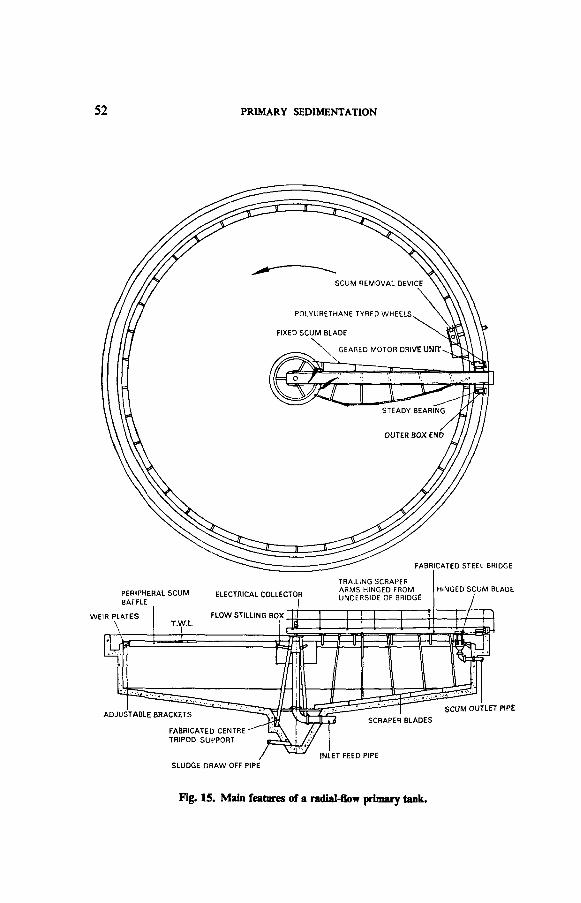
52 PRIMARY SEDIMENTATION
FABRICATED STEEL BRIDGE
HINGED SCUM BLADE
SCUM OUTLET PIPE
FABRICATED CENTRETRIPOD SUPPORT
SLUDGE DRAW OFF PIPE
INLET FEED PIPE
Fig. 15. Main features of a radial-flow primary tank.

RADIAL-FLOW TANKS 53
3.3.2 Retention period
The retention period is usually about 2 h at maximum flow, sometimesreducing to 1-5 h when the maximum receiving full treatment exceeds3DWF.The capacities of radial-flow tanks of diameters ranging from 12 to 30 m andwith floor slopes ranging from 1\° to 22£° are given in Table 4.
3.33 Dimensions
TABLE 4. CAPACITIES OF RADIAL-FLOW TANKS
Tankdiameter
(m)
12
15
18
21
24
27
30
Volume per mof side wall
depth
113
177
254
346
452
572
707
Volume of conical portion
714°
30
58
101
160
238
339
465
Floor
10"
40
78
135
214
319
454
623
slope
15"
61
118
205
325
485
690
947
2254°
94
183
316
502
750
1067
1464
Diameter. The diameter of a radial-flow tank is controlled by the designof the scraper, ranging from a minimum of 5 m to 15 m for a fixed-bridgescraper to 50 m for a rotating-bridge scraper. Above this diameter a specialdesign of both scraper and tank is necessary.
Depth of vertical side. The depth of the vertical side should not be less than1 -5 m from the water level and it is usually from one sixth to one tenth of thediameter.
Slope of floor. The floor slope depends upon the type of scraper used,but a 1\° slope to the horizontal is common. In a series of tests with modeltanks, Clements34 found that a slope of 10° gave the best results; flat-bottomed tanks gave a slightly lower performance and the worst results wereobtained with tanks having floor slopes of 20° to 30°. If too great the heavysludge may be swept to the centre so quickly that it is inadequately mixedwith the lighter sludge and an uneven load is imposed on the scraper.

5 4 PRIMARY SEDIMENTATION
3.3.4 Weir overflow rate
If the weir overflow rate at maximum flow is less than 100 m3/m d therate at minimum flow will be too low to prevent surface tension from affectingflow over the weir. If the weir is continuous, the diameter of a radial-flow tankis therefore limited because of the relatively long length of its peripheral weir.However, this difficulty may be overcome by using other forms of weir (see3.4.2).
3.4 Design3.4.1 Inlet
The feed pipe usually runs beneath the floor of the tank to the centre,then turns upward and ends in a bellmouth a little below water level or in adiffuser with vertical or horizontal slots or circular ports discharging belowthe surface. Alternatively, the feed pipe may enter through the side of thetank, although in this position it might interfere with the motion of the scraperand the effects of directional velocity imparted by the change in direction froma horizontal to a vertical flow might not have been eliminated before discharge.
When the feed pipe ends in a bellmouth, the outlet may be surrounded by acylindrical diffuser which, in turn, is surrounded by a deflector drum. Thediffuser has a series of vertical slots and the sewage passing through them isdeflected downward by the deflector drum. The purpose of the diffuser isto dissipate the kinetic energy of the incoming sewage and to promoteuniform distribution. Alternatively, there might not be a deflector drum, thesewage flowing through ports directly into the body of the tank. Whichevermethod is adopted, the design must ensure that settled sludge is not disturbedby the flow of sewage. Diffusers and deflector drums vary greatly in design,from a steel, aluminium alloy or fibreglass drum mounted on or supported bya feed pipe, or slung from the bridge and rotating with the scraper, to aconcrete box with ports supported on piers built up from the edge of thesludge hopper.
The diameter of the deflector drum varies, according to the design ofthe tank, from 10 to 20 per cent of the tank diameter, the surface area of thedrum ranging from 1 to 4 per cent of the tank area, although sometimes adrum with an area equal to 5 per cent of the tank area is used35. The area ?fthe drum is usually neglected when calculating the surface loading. Thedeflector drum should extend 0-15 m above water level and the depth belowwater level ranges with different types of scraper and different designs oftank from 40 to 95 per cent of the side water depth of the tank. Scum usually
RADIAL-FLOW TANKS 55
collects within the drum and is difficult to remove unless there is an openingat the water level through which the scum can be swept into the body of thetank. Alternatively, the drum may be omitted and the diffuser extended toabove water level so that the scum can pass through the slots or ports.
The inlets to the radial-flow primary tanks at Mogden works33 wereoriginally as shown in Fig. 16 (a), with a deflector drum surrounding thecentral inlet. They were then altered as shown in Fig. 16 (b) because it wasfound that deflection of the sewage downward tended to interfere with sludgedeposited at floor level. The feed pipe now discharges just below the bottom ofthe deflector drum and the whole is surrounded by a diffuser to promote apure radial flow.
(a)
(b)
Fig. 16. Radial-flow primary tank at Mogden Works: (a) before modification,(b) after modification.
However, White and Allos22, experimenting with a full-scale radial-flowprimary tank, found little difference in the results before and after removal ofthe vertical feed pipe and deflector drum and they considered that improve-ments in the design of inlets were unlikely to lead to a significant improvementin performance.

56 PRIMARY SEDIMENTATION
3.4.2 Outlet
The outlet is usually a peripheral weir, which is protected by a scumbaffle and discharges into a channel. It is important that the weir shall belevel throughout its length and if continuous it should preferably be fittedwith adjustable metal weir plates so that these can be accurately levelled. Toincrease the overflow rate the weir may either be castellated or consist of aseries of V-notches, which should be sufficient in number to limit the maxi-mum discharge per notch to 30-40 m3/d, with the depth of flow being re-stricted to 35 mm. An advantage of the V-notch weir is that an accuratesetting of the weir plate is less important. Castellation may reduce theeffective length of the outlet weir by up to 60 per cent, depending on thenumber and length of the castellations.
3.4.3 Floor
The floors of radial-flow tanks slope from the periphery to a centralsludge hopper and often have a concrete fillet between the vertical wall and thefloor. When it is being laid the floor should be screeded as accurately aspossible and consideration should be given to the position and finish ofexpansion joints.
The sludge hopper is usually conical and should be sufficiently deep topromote desirable consolidation of the sludge and to prevent overlyingwater from breaking through to the sludge outlet during withdrawal. Theside should slope at least 60° to the horizontal and when the tank is to bedesludged once a day the hopper should hold at least one day's production ofsludge. With a production of 0-07 kg dry solids/hd d and sludge at 5 per centsolids, a capacity equivalent to 1 -4 litres/hd d will be required. In addition,capacity will be needed for storing solids in secondary sludge and worksliquors returned to the primary sedimentation tanks. The feed pipe usuallyenters the tank in the sludge hopper and the supporting beams may interferewith access to the sludge outlet if the hopper is of limited diameter.
3.4.4 Collection of sludge
Scrapers suitable for radial-flow primary tanks are of two types, i.e.:(a) fixed-bridge scrapers, and(b) rotating-bridge scrapers.
Ring scrapers were at one time employed but are not currently being installedbecause of their high cost. Suction-type scrapers are usually used in secondarysettlement tanks and therefore, as with chain scrapers, are not dealt with inthis manual.

RADIAL-FLOW TANKS 57
Fixed-bridge scrapers. With this type of scraper (Fig. 17) the bridge spansthe tank and supports a walkway with handrailing providing access to thedrive unit. The drive unit is mounted at the centre of the tank and consists of
Filed Bridge
Fig. 17. Radial-flow tank with fixed-bridge scraper.

58 PRIMARY SEDIMENTATION
an electric motor driving a vertical shaft through reduction gearing. The shaftsupports the two scraper arms and has a special watertight bearing at floorlevel.
The feed pipe is usually laid beneath the floor to the centre of the tank andthen turns upward to discharge into a deflector drum. In one design the feedpipe discharges into a vertical rotating pipe terminating below the watersurface in a diffuser which is surrounded by a rotating deflector drum. Ifentering the tank from the side, the pipe can be supported by and under thebridge but in this case difficulty is experienced in operating a scum skimmingblade without the supporting members fouling the feed pipe. In one design,however, this difficulty has been overcome by supporting the skimming bladefrom a rotating deflector drum so that the scraper arms rotate beneath thepipe and the scum skimming blade above it.
The electric supply cable for the motor is carried along the bridge and thisarrangement is much simpler than the power supply to a rotating-bridgescraper.
With tanks up to 15 m diameter the bridge structure is usually fabricatedfrom channels or joists suitably braced, whilst a lattice design is used fortanks of a larger diameter.
Rotating-bridge scrapers. There are two types of rotating-bridge scraper,viz. full bridge and half bridge, extending over the diameter and radius respec-tively of the tank. A full-bridge scraper (Plates 6 and 7) is usually centrallysupported and one end of the bridge carries the drive motor, the other endbeing supported on an idler wheel. A half-bridge scraper is pivoted at thecentre and is supported on a "spider" or cage attached to the feed pipe, on aconcrete platform supported by a steel tripod, or on legs (usually of reinforcedconcrete) rising from the sludge hopper.
The bridge, which carries the scraper blades, is driven by a motorizedgear-box and depends on a traction grip on a rail or tank coping, the wheelshaving polyurethane tyres. Most designs incorporate a scraper blade toprevent the accumulation of snow or ice on the track.
The electric supply system is more complicated than with a fixed-bridgescraper, the cable having to be laid in a duct in or under the tank floor andcarried up the side of the feed pipe or in the central column. However, withtanks up to 18 m diameter, the cable may be carried overhead, being sup-ported by a catenary wire. When laid in a duct, modern methods of sealinghave reduced the earlier hazards. In either case there is a slip-ring assembly atthe tank centre, with a cable to the drive motor.

RADIAL-FLOW TANKS 59
A push-button control unit with an isolator is installed on the bridgeadjacent to the motor, or if located near the tank it is much more accessible incase of emergency or during desludging. Further, a land-based control can beplaced in a weatherproof housing, which facilitates maintenance, and ifdesired, automation can be more readily applied. From the point of view ofsafety, all machines must comply with the ESB regulations and the FactoryActs.
Scraper blades. In the earlier design of scraper a continuous helical bladewas used but this was unable automatically to adjust itself to the profile of thefloor if the screed finish was inaccurate.
Blade arrangements now normally used in primary sedimentation tanksare either:
(a) a series of blades arranged in echelon (Plate 8) at an angle of about45° to a rotating radial arm (Fig. 17), the number depending on thediameter of the tank, or
(b) a series of straight-blade sections arranged to form a continuousvolute (Plate 7 and Fig. 18).
With blades arranged in echelon the sweeping process is more gradualsince, unless the blades overlap, the unit must make as many revolutions asthere are blades to convey an annulus of sludge from the periphery of thetank to the central hopper, although less load is imposed on the scrapermechanism.
Scraper blades are often attached to hinged arms and are trailing,relying on their weight or on a spring-loaded action to prevent their beinglifted from the floor by an accumulation of sludge. With one design the angleof contact with the floor produces an undershot effect and it is claimed that inthis case an accumulation of sludge tends to promote contact. When on ahinged arm the blade automatically adjusts itself to the profile of the tankfloor.
Blades are edged with renewable rubber or rubber substitute wearingstrips or have a metallic edge. However, the weight of the trailing portionshould not be such as to produce undue wear, and with some of the largerscrapers buoyancy devices are attached to the blades to reduce this.

60 PRIMARY SEDIMENTATION
Fig. 18. Radial-flow tank with rotating half-bridge scraper.
Scraper blades are supported from a framework carried from the bridgeand if freely attached to the bridge structure they can be lifted for examina-tion without having to empty the tank.
Speed of scrapers. With primary sedimentation tanks the peripheral speedof the scraper may be within the range of 1-8 to 2-5 m/min. The WorkingParty on Sludge Disposal36 recommended that the speed should not exceed1 -5 m/min, but especially with large tanks, if it is too low scum will rotatewith the skimmer blade and not be swept to the periphery.

RADIAL-FLOW TANKS 61
Wall scrapers. An additional scraper is sometimes attached to the rotatingframework carried by the bridge to maintain the cleanliness of the verticalside wall of the tank (Plate 9).
3.4.5 Sludge withdrawal
Sludge is withdrawn from the central hopper through a pipe runningunder the floor of the tank to an external inspection chamber where the rate ofwithdrawal can be controlled by a telescopic screw-down bellmouth weir oran adjustable straight weir. The valve may be hand or power actuated,control being by push-button, or the sequence of operation may be partiallyor fully automatic using one of the methods described in 5.2.5.
A recent device37 uses compressed air to assist withdrawal of sludge. Airis introduced into a vertical sludge pipe, about 2 m below the water surface,and accumulates until there is sufficient to form a piston which then rises andin doing so lifts a column of sludge so that it discharges into the inspectionchamber. The air supply, which is controlled by a solenoid-operated valvewith timer, is then cut off. Before air is again admitted, the void which hasbeen created fills with sludge as a result of pressure due to the differentialhead. Since the air acts as a pump rather than an air lift, the sludge does notbecome impregnated with air. Also, with the outlet being about 0-075 mabove tank water level, there is no loss of head as with normal dischargethrough a telescopic valve and the discharge ceases automatically if there is anelectrical or mechanical failure.
A low-level outlet to the sludge inspection chamber is often provided.This enables a greater hydraulic head to be applied when removing a thicksludge.
3.4.6 Scum collection and withdrawal
Scrapers for primary sedimentation tanks carry a special scum skimmingblade (Plate 10) so that as the scraper rotates the scum is swept towards abaffle supported from the peripheral wall and is withdrawn each time thescraper makes either a half or one revolution, according to the number ofarms. Withdrawal may take place manually by sweeping the scum over aweir penstock, or automatically by the scum being swept up a ramp (Fig. 19)or tilting tray (Fig. 20) by a hinged blade so that it falls into a trough or hopper,from which it may be flushed by opening a valve. In some designs the outerend of the skimming blade is set back to form a retaining pocket (Plate 10),the scum being automatically withdrawn. Another form of outlet is a slottedpipe fixed in a recess in the tank weir wall (Plate 9); the pipe is pivotally

62 PRIMARY SEDIMENTATION
mounted and counterbalanced so that it can be operated by a cam mountedon the bridge. Flushing of scum from the hopper or trough may be ac-complished by the automatic depression of a hinged flap immediately afterthe scum has been withdrawn, permitting water from the tank to flow intothe hopper.
SUPPORT STRUCTURE
TENSION ADJUSTER
SCRAPER BLADE--i
RAMP
SCUM HOPPER
SCUM OUTLET PIPE
SWIVEL JOINT—
RAMP
SCRAPER BLADE—
-SKIMMER BLADt/ ^
HINGED SKIMMER FLAP-
Fig. 19. Scum removal equipment using a ramp with a hinged scraper blade.
3.5 Performance
The Water Pollution Research Laboratory5 investigated the performanceof two radial-flow primary tanks, each equipped with a central flocculatorchamber, when treating sewage which had been macerated and screened. Thetwo tanks operated at slightly different rates of flow and the tests wereconducted over a period of two days. Each tank had a capacity of 1086 m3.One had a mean retention period of 8-2 h and the surface loading rangedfrom 2-8 to 19-4 m3/m2 d, with an average of 12-2 m3/m2 d. During passagethrough this tank the SS content of the sewage was reduced from 370 to110 mg/1, i.e. a reduction of 70 per cent.

RADIAL-FLOW TANKS 63
With the other tank the retention period averaged 5-2 h and the surfaceloading ranged from 12-2 to 26-0 m3/m2 d, with an average of 19-0 m3/m2 d.The SS content of the sewage was reduced from 359 to 117 mg/1, i.e. areduction of 67 per cent.
Strikerpin
Operatingcam
T.w.l.
Scum trap approaching hopper
Scum trap passing hopperFig. 20. Scum removal equipment using a tilting tray.
Table 5 gives information on radial-flow primary tanks at a number ofsewage works and shows their performance. In most cases the SS content ofthe crude sewage was lower and that of the effluent higher, the percentageremoval of solids being less, than with the tanks investigated by the WaterPollution Research Laboratory. It appears that with radial-flow tanks theSS content of the effluent usually exceeds 100 mg/I and that SS removalsrange from 50 to 75 per cent.
The dry solids content of the sludge produced depends on many factors,including its inorganic content, whether it includes secondary sludge or worksliquors, and the skill of the operator, but it is usually within the range of3-0-6-5 per cent.

TABLE 5. PERFORMANCE OF RADIAL-FLOW PRIMARY SEDIMENTATION TANKS
Sewage-tieatmani
works
BarnsleyLundwood
Bournemouth(Holdenhurst)(Kinson)
Darlington
Hogsmill Valley
Mailing
Oldham
Oxford
Averagedaily(low(tern)
15-6
8689
143
9-8
4 5
170
232
Num-ber
6
22
2
4
2
1
8
Diam-eter(m)
16-7
24418-3
27-6
30-5
19-8
33 5
19-5
Primary tanks
Sidewall
depth(m)
3 0
2-72-1
2-1
3-2
2-4
3-3
4-2
Ratioof
radiusto side
walldepth
2 4
4 54-4
6-6
4 8
4 1
5-1
2-3
Weirover-flowrate*(m3/md)
52
5877
83
108
38
161
47
Surfaceload-Ing*(m*/rnJd)
11-8
9 216-9
120
150
7-3
19-4
9 7
Reten-tion
period*(h)
7 0
793-5
6 0
6-7
9-7
5 2
7-8
Suspended solids
Crudesewage(mo/I)
370
420275
295
305
490
165
405
Settledsewage(mg/l)
150
125135
140
100
135
95
100
Re-moval(%)
60
7151
53
67
72
43
75
BOO
Crudesewage(mg/l)
400
308265
280
275
405
195
370
Settledsewage(mg/l)
250
150155
180
150
170
115
176
Re-moval(%)
38
5041
36
45
58
41
53
Sludgeproduction
Average(m'/d)
114(81)
59 (AL)45 (AL)
137-KB)
327 (AL)
46
110 (ABL)
86
Litres/hdd
1-5
1-31-1
1-5
1-75
1-5
0 7
1 0
Sludgedry solids
Percent
4 6
4-15 5
5 9
4-4
5-6
6-9
5 3
Vola-tile
con-tent
%
78
7878
64
75
75
63
73f
Ref.No.
38
3939
25
10
40
29
30
* Based on average dally flowt Sludge from radial-flow tanks and horizontal-flow tanks Is combined
A Includes surplus activated sludgeB Includes sludge from biological filtersL Includes works' liquors
wmaim
I5

Plate 1. Travelling-bridge scraper with vertical blade.
Plate 2. Travelling-bridge scraper with trailing blade.

Plate 3 . Horizontal-flow tanks equipped with flight scrapers.

Plate 4. Inlet end of horizontal-flow tank equipped with buoyant flight scraper.
Plate 5. Outlet end of horizontal-flow tank equipped with flight scraper, showingtubular boom at end of travel and scum outlet.

Plate 6. Rotating half-bridge scraper with blades arranged in echelon.

Plate 7. Rotating half-bridge scraper with straight-blade sect*sections.

Plate 8. Rotating half-bridge scraper with blades arranged in echelon.
Plate 9. Radial-flow tank, showing slotted scum outlet and scraper for vertical wall.

Plate 10. Rotating half-bridge scraper, showing scum skimming blade with retainingpocket, hinged blade, ramp and scum trough.
Plate 11. Detector head of magnetic flow meter.

pMOI 2SSSR1ES
ZERO SLUDGE BLANKET OETECTOfl CALIBRATE
Plate 12. Example of an optical sludge level detector.

4. Upward-Flow Tanks
4.1 Arrangement
Figure 21 shows diagrammatically the main features of an upward-flowtank.
(B) (C) CD) CE)
Fig. 21. Main features of an upward-flow primary sedimentation tank.
A, Effluent channel; B, rodding eye; C, top water level; D, bcllmouth inlet; E, stilling box;F, feed pipe; G, peripheral weir; H, side water depth; I, sludge pipe; J, sludge sump;
K, scum baffle.
4.2 Application
At one time upward-flow tanks were often used on small and medium-sized works for primary sedimentation, but with the introduction andincreasing popularity of the mechanically-desludged radial-flow tank,upward-flow tanks are now less frequently installed except for small works.
— 65 —

66 PRIMARY SEDIMENTATION
Upward-flow tanks cost more to construct than horizontal-flow orradial-flow tanks, except when serving a population of less than 800016.Also they are difficult to construct in bad or waterlogged ground because oftheir great depth, although in such cases tanks have been constructed withfour hoppers to reduce the depth. When the only alternative was manuallydesludged horizontal-flow tanks, upward-flow tanks had the great advantagethat the sludge could be withdrawn without emptying the tank and with aminimum of inconvenience. However, sludge was apt to lodge on the slopingsides, particularly in the corners if pyramidal where the slope was at aminimum, and turn septic, causing sludge to rise to the surface, whereremoval was difficult. If the sludge outlet became blocked difficulty wasexperienced in clearing the blockage and it might even have been necessary toempty the tank, involving the use of a portable pumping set. With desludgingtaking place through a pressure differential, inefficient operation couldeasily result in the withdrawal of sludge with a low solids content. However,if properly operated, upward-flow tanks are highly efficient and produce agood effluent.
4.3 Design Criteria
4.3.1 Upward velocity
This should not exceed 1 -8 m/h and is often about 1 -2 m/h at maximumflow.
4.3.2 Surface loading
With an upward velocity at the tank surface of 1 -2 m/h at maximum flow,the surface loading will be 28-8 m3/m2 d.
4.3.3 Retention period
The nominal retention period is usually 2 to 3 h, depending on the designfrequency of desludging.
4.3.4 Dimensions
Lower portion. If pyramidal, the sides should slope at an angle of notless than 60° to the horizontal, with the corners having a slope of about 50°.With a circular tank the slope may be 45° to the horizontal.
Upper portion. Tanks range from 5 m to 9 m square; if less than this thedepth of water over the weir at minimum flow will be less than 2-5 mm and theflow will be affected by surface tension, and if greater, with the pyramidalportion having a 60° slope, the depth and consequently the cost of construction

UPWARD-FLOW TANKS 67
will be excessive. A tank with sides 7-5 m square, the surface loading being28-8 m3/m2 d, will treat 1620 m3/d at maximum flow. From the length of thesides and the retention period, the total volume of the tank can be calculated.The volume of the upper portion is obtained by deducting the volume of thepyramidal portion, and knowing the surface area, the depth of the verticalsides may be calculated.
4.3.5 Weir overflow rateWith a tank 7-5 m square and treating 1620 m3/d at maximum flow, the
maximum overflow rate will be 54 m3/m d, which will mean that at minimumflow the velocity will be much too low to be self-cleansing, so V-notch weirsor castellated weirs will need to be used because of this.
4.4 Design4.4.1 Inlet
The feed pipe enters the side of the tank, turns through 90° when it reachesthe centre, terminates in a bellmouth and discharges in a vertical directiona short distance below water level. It should be of such a size that the velocitydoes not fall below 0-3 m/s at minimum flow. Surrounding the feed pipeis a deflector or stilling box, from 1 -0 to 1 *22 m square, with the upper end0-15 m above water level and extending to a little below the bottom of thevertical walls. The deflector box may be of asbestos cement, steel, aluminiumalloy, fibreglass or plastics and, together with the feed pipe, is supported bybeams spanning the tank; these also support a chequer-plate or open-meshwalkway with handrailing to provide access to the central feed.
4.4.2 OutletThe outlet is usually a peripheral weir protected by a scum baffle. The
weir should preferably be fitted with adjustable metal plates or it may becastellated or consist of a series of V-notches. Alternatively, double-edgedtroughs may span the tank a short distance from two of the sides.
4.4.3 Lower portion of tankThe steeply sloping sides are necessary to ensure that sludge slides down
them without sticking; since the weight of the sludge causing motion is lesswhen it is submerged, a steeper slope is necessary than when the sludge isexposed. At the bottom there may be a small sump into which the sludge pipedips. Garner41 considered this to be important as it helps to direct the sludgeto the point of maximum pressure at the outlet and so reduces the possibilityof water breaking through when desludging the tank. However, such a sumpis expensive to construct and it is now usual for the bottom to be a squarewith 0-75 to 1 0 m sides.
68 PRIMARY SEDIMENTATION
4.4.4 Sludge withdrawal
Sludge is withdrawn from the bottom through a pipe located inside thetank and terminating a short distance above water level. At least 1*2 m, andpreferably 1 -5 m, below water level the pipe has a horizontal branch whichdischarges into an inspection chamber at the side of the tank. Sludge iswithdrawn through this branch, whilst the vertical extension is used as arodding "eye". Sludge is withdrawn under pressure due to a differential headand discharges over a telescopic screw-down bellmouth weir or a swingingarm. The mouth of the sludge pipe should be 1£ pipe diameters above thebottom of the tank to prevent blockage at this point, and if it is chamferedso that it is in a vertical plane this will facilitate both withdrawal of sludge androdding, if this becomes necessary. The pipe should be at least 150 mmdiameter.
4.4.5 Scum collection and withdrawal
Scum is retained by a baffle which should be at least 0-3 m from theperipheral wall and supported by it. At intervals a light squeegee is used forsweeping the scum to an adjustable weir at the side of the tank. Scum will alsocollect within the deflector box and this should be removed at intervals.
4.4.6 Washout
A valve-controlled washout discharging into the inspection chamber atfloor level provides water for flushing the sludge main and enables a portion ofthe tank contents to be drained by gravity when it is necessary to empty thetank.
4.5 Performance
The Water Pollution Research Laboratory5 investigated the performanceover a period of four days of a circular upward-flow primary sedimentationtank at a works when treating sewage which had passed through comminutorsand screens, with sludge from biological filters being added every morning.The tank had a capacity of 273 m3 and the surface loading ranged from1 -4 to 25-5 m3/m2 d, with an average of 10-8 m3/m2 d. The SS content of thesewage was reduced from 477 to 164 mg/1, a reduction of 65 per cent. Thisreduction is similar to that reported for upward-flow tanks at other sewageworks, although the data available are very limited.
The dry solids content of the sludge withdrawn from upward-flow tanksvaries widely, depending on the frequency of withdrawal and the skill of theoperator, but averages 3 to 4 per cent.

5. Operation and Maintenance ofPrimary Sedimentation Tanks
5.1 Sludge Level Detection
Instruments which are currently manufactured for detecting sludge levelshave either optical or ultrasonic sensing heads.
The optical sensors, of which an example is shown in Plate 12, are of the"extinction" type similar to that described by Briggs and Knowles42 (Fig. 22).The output is arranged to give either an increase in reading to a presentmaximum value, or a fall to zero. In practice in either case, there is usuallya slight change in reading as the probe is lowered through the supernatant
4-CORE CABLE
CONDUIT
'SLEEVED' SOLDER JOINTS
COLD SETTING SILAS7OMER
RUBBER OR PLASTIC TUBE PACKHG PIECE
BULBBULB HOLDER.
COLD SETTINGS1LASTOMER
CONDUIT
RUBBER OR PLASTIC TUBE HACKING PIECE
COLD SETTING SILASTOMER
PHOTOCELL
Fig. 22. Diagram of optical assembly of photoelectric sludge-level detector.
liquor, followed by erratic changes in the transitional region just above thesludge, over depths varying between a few centimetres and 1 m, dependingupon the sludge properties and the size and design of the tank. The sludge levelis taken as the mean depth indicated by a high (or in some instruments, a
— 69 —

70 PRIMARY SEDIMENTATION
zero) reading, obtained as the probe is passed through the interfacealternately from above and below.
Ultrasonic instruments can detect the level of an interface from the"time of flight" of a reflected signal or the attenuated value of pulsed highfrequency sound. Reflection types work best where there is a sharply-definedboundary between air and a liquid or solid. Probes measuring the attenuationof sound intensity make a direct measurement through a known sludge pathlength and are less likely to suffer from extraneous reflected signals. Thistype has been shown to be able to detect sludge levels, and also to be able tomeasure the concentration of sludge.
Both optical and ultrasonic attenuation types have been designed to followthe rise and fall of the sludge/water interface. The optical instrument canalso be calibrated to give an approximate value of the concentration of SSin the supernatant liquor, while the ultrasonic instrument can be calibratedsimilarly in terms of sludge density. Both types have an electrical outputsuitable for control purposes.
5.2 Withdrawal of Sludge
The frequency with which tanks are desludged will be controlled by suchfactors as:
(a) the type of tank and the type of scraper,(b) the requirements of other sections of the treatment plant, i.e.
subsequent dewatering and other processes (with some dewateringprocesses the sludge is dealt with in batches, whilst for digestionunits it is better to add the sludge a little at a time and often),
(c) the need to prevent the sludge from turning septic whilst in thetank, with resulting rising sludge and scum formation,
(d) local conditions.
The water content of the sludge as withdrawn should be such that it can bepumped without difficulty but when the sludge is to be digested the solidscontent should be as high as practicable to avoid wasting heat, reducing theretention period in the digestion tanks and producing an excessive amount ofliquor.
Local conditions to be taken into consideration include:(a) the industrial waste content of the sewage,(b) any tendency for the sewage to turn septic,

OPERATION AND MAINTENANCE OF PRIMARY SEDIMENTATION TANKS 71
(c) the air and sewage temperatures, and(d) whether secondary sludge or works liquors are being returned to
the primary sedimentation tanks.
The solids content of the sludge will depend to a large extent on theefficiency of the operator if withdrawal is controlled manually. Fig 23 showsthe effect on the volume, when a denser sludge is withdrawn, of the dry solidscontent of the sludge.
10
9
8
7
6
| 5
h3
2
1
01
\
-
-
i i
2 3Dry
^ - — _ _
i i i i i
4 5 6 7 8 9solids (per cent)
Fig. 23. Relation between dry solids content and volume of sludge.
However, the rate at which sludge is withdrawn is important. This mustnot be so great that there is a possibility of over-lying water breaking throughto the sludge outlet, or so low that there is a possibility of solids settling in thesludge pipe and causing blockages.
If the needs of other sections of the treatment plant require that the sludgeshall be stored before treatment, a separate tank should be provided ratherthan relying on storage in the primary tanks.
5.2.1 Manually-desludged horizontal-flow tanks
A manually-desludged tank should be emptied in dry weather when thesewage flow is relatively low. The tank is usually taken out of service theevening before, or at least an hour in advance, to allow the sludge to settle.Supernatant water is then withdrawn through a floating-arm draw-oft* or atelescopic valve until only sludge is left in the tank. When approaching thesludge level, the rate of withdrawal is slowed down to enable as much wateras possible to be withdrawn without disturbing the sludge. The sludge is then

72 PRIMARY SEDIMENTATION
pushed to the outlet by workmen using squeegees. Finally the floor is hoseddown with supernatant water or final effluent. Valves, penstocks and super-natant water draw-offs are cleared of rags or solid matter and the sludge pipeis flushed with sewage before the tank is refilled. Since the work is dirty,arduous and time-consuming, manually-desludged tanks are used only onsmall works, and even then they are now usually emptied by a tank-emptyingvehicle.
The Royal Commission on Sewage Disposal43 recommended thatmanually-desludged primary sedimentation tanks should be emptied atleast once a week, but wherever possible such tanks should be modified totake a suitable mechanical desludging device.
5.2.2 Mechanically-desludged horizontal-flow tanks
In practice, the frequency of desludging varies at different works fromonce a shift to once a day, and with small works once every two days. Thetime taken to withdraw sludge will depend on the frequency of desludging,the length of the tank, the speed of the machine and, with a machine that istransferred from one tank to another, the time taken to make the transfer.When desludged once a day the time may vary from 0-75 h to 1 -5 h per tank.
5.2.3 Radial-flow tanks
With this type of tank it is usual to start the scraper from 15 min to 1 hbefore starting withdrawal in order to concentrate the sludge in the centralhopper. On some works, however, the scrapers are operated on a time basis orcontinuously. Intermittent use of scrapers reduces wear of scraper bladesand wheel tyres.
Attempts have sometimes been made to withdraw sludge continuouslythroughout the 24 h to provide a constant feed to digestion tanks but the rateof withdrawal is then so slow that the telescopic draw-off valve on the sludgepipe may become blocked. In practice, the maximum frequency is onceevery 8 h. At many works the operator draws sludge from each of a series oftanks in turn and this sequence is repeated until desludging has been com-pleted.
5.2.4 Upward-flow tanks
The frequency with which sludge should be withdrawn from upward-flowtanks will be determined by experience but will be at least twice a week.When starting to desludge a tank the valve on the sludge pipe should beopened slowly since any sudden change in the rate of discharge may cause

OPERATION AND MAINTENANCE OF PRIMARY SEDIMENTATION TANKS 7 3
overlying water to break through to the outlet. The valve may then bepartially closed to control the rate of withdrawal. When the density of thesludge is seen to fall the valve is closed and it is left for about 10 min whilstfurther sludge slides down the slopes to the outlet. The valve is then openedagain and further sludge withdrawn, the cyck being repeated until all thesludge has been removed.
When the lower portion of the tank is conical a weighted drag chain maybe used for dislodging sludge from the sides.
If the sludge pipe becomes blocked the blockage may be removed byramming a plunger down the pipe from the rodding "eye", or if this is notsuccessful a jet of water or compressed air issuing from a tube thrust down thepipe may be used. If this fails to clear the blockage it will be necessary toempty the tank using a mobile pump after first running off supernatant waterdown to the level of the washout.
5.2.5 Automatic control of sludge withdrawal
Remote control by closed-circuit television. This method is used on alimited number of large works. The desludging sequence is started manuallyby push-button and a monitoring camera showing the sludge being with-drawn over an adjustable bellmouth is switched on. A view of the sludge istransmitted over closed-circuit television to a central control building whereits withdrawal is monitored. When the operator judges that withdrawalshould cease the valve on the draw-off is closed by push-button.
Control by manual start and automatic stop. Richards and Kirk44 foundthat there was a direct relationship between the dry solids content of sewagesludge and its specific gravity or density. A measure of the density of sludgemay be gained by methods based on the differential air-reaction principle oron its viscosity. There is also a relation between the electrical conductivity ofthe sludge or its absorption of gamma rays, and the dry solids content of thesludge. It was therefore considered that measurement of one of these as thesludge flowed along a pipeline might be used as a means of monitoring theflow, with the valve in the pipeline being closed automatically when a pre-setand adjustable level had been reached. In 1962 the Water Pollution ResearchLaboratory45 studied a number of methods of measurement and produced aviscometer which they used "for the rapid determination of the solids contentof crude sludges from 5 different sewage works, using the appropriatecalibration curve for each works". However, it was considered that "the useof ultrasonics might be more satisfactory in the long term, provided thatportable and sufficiently inexpensive equipment can be developed".
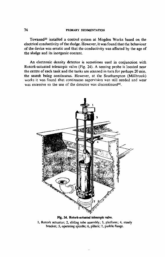
74 PRIMARY SEDIMENTATION
Townend23 installed a control system at Mogden Works based on theelectrical conductivity of the sludge. However, it was found that the behaviourof the device was erratic and that the conductivity was affected by the age ofthe sludge and its inorganic content.
An electronic density detector is sometimes used in conjunction withRotork-actuated telescopic valve (Fig. 24). A sensing probe is located nearthe centre of each tank and the tanks are scanned in turn for perhaps 20 min,the search being continuous. However, at the Southampton (Millbrook)works it was found that continuous supervision was still needed and wearwas excessive so the use of the detector was discontinued46.
Fig. 24. Rotork-actuated telescopic Talre.
1, Rotork actuator; 2, sliding tube assembly; 3, platform; 4, steadybracket; 5, operating spindle; 6, pillars; 7, puddle flange.

OPERATION AND MAINTENANCE OF PRIMARY SEDIMENTATION TANKS 75
Richards and Kirk44 experimented at Bristol with two makes of instru-ment based on the air-reaction principle but found that the results were"unreliable and erratic". They therefore decided to use a magnetic flowmeter (Plate 11) on each draw-off from the primary sedimentation tankswhich, after being calibrated against a gamma-ray meter, would record therate of flow through the pipe and therefore the viscosity (which is related to thesolids content) of the sludge, they having calculated that the rate of flow inthe pipe would vary from 26-5 1/s with sludge at 8 per cent dry solids to38 1/s with sludge at 4 per cent dry solids. In 1969 Lewin47 reported thatmagnetic flow meters at Oxford were "working to within acceptable limits".
A A
Sludgepipe
Sludge cascadinginto chamber
Sludgepipe
Fig. 25. Arrangement for automatically stopping withdrawal of sludgefrom a sedimentation tank.
An arrangement for automatically stopping withdrawal of sludge fromtanks which is being used at several works is shown in Fig. 25. This dependsfor its operation on the arc described by the sludge as it cascades from ahorizontal pipe into a conical chamber. When thick, the "throw" of thesludge is short but as the sludge becomes thinner the "throw" increases untilit touches an electrode, which causes a pneumatically-operated valve to closeand stop withdrawal. The position of the electrode is adjustable and it canbe set, according to experience, so that withdrawal ceases when the dry solidscontent of the sludge has fallen to a pre-determined level. When startingwithdrawal a delay mechanism allows for the initial discharge of a thinsludge from the pipeline.
An instrument has recently been placed on the market48 which ultra-sonically senses the density of the sludge. An electronic control unit generates

76 PRIMARY SEDIMENTATION
an electrical signal which is converted into an ultrasonic signal. This isdirected across the pipe section through the sludge where it is received andre-converted into an electrical signal. This signal is amplified and used toactuate a relay which closes the valve on the draw-off when the density of thesludge has fallen to a certain level. Sonic equipment is to be used in connec-tion with sensing density differences in sludge being withdrawn from primarysedimentation tanks at the Carbarns works49.
Another new instrument50 passes gamma rays through the sludge. Thesource head, which is supplied with a caesium-137 source, is clamped to thedraw-off pipe. Gamma rays pass through the sludge and are absorbed inproportion to its density. The rays reaching the detector produce a currentwhich is inversely related to the density. The detector chamber is heated andthermostatically controlled to eliminate temperature variation and moisturecondensation. It is claimed that the device can measure dry solids concentra-tions ranging from 0 1 to 10 per cent.
Recently the Water Pollution Research Laboratory51 have reported thatthey are investigating a method of measuring sludge solids concentrationsbased "on measurement of the root mean square value of the noise componentof a signal from a simple conductivity sensor and correcting the measurement(by means of an inverse multiplication technique) for variations in the meanconductivity of the sample", it being considered that this might form "thebasis of design of a relatively cheap and robust instrument for continuousmonitoring and control purposes".
Automatic control of desludging sequence. Timers may be used forinitiating and controlling the desludging sequence at set intervals, operationof the valves on the sludge draw-offs being controlled by cams actuated by ageared motor, the cam settings determining the order in which the valves areoperated. At the end of the sequence the timer stops the motor. This methodis used at Sheffield (Blackburn Meadows) works11 for controlling the with-drawal of sludge by electrically-driven centrifugal pumps.
Desludging using air-lift principle. Equipment which operates on theprinciple of an intermittent air lift has successfully been introduced on manyworks. Adjustable timers operate a solenoid valve fitted in the air dischargepipework, controlling the amount of air delivered and the period of timebetween each discharge of air. Each discharge of air lifts a quantity of sludge,with a "piston" effect from the sludge pipe52.

OPERATION AND MAINTENANCE OF PRIMARY SEDIMENTATION TANKS 77
5.3 Operating Difficulties
Rising sludge. If the sludge rises to the surface in all the tanks due togasification, evidenced by bubbles rising with the sludge, this may be due toone or more of the following causes:
(a) the frequency of desludging is inadequate,(b) sludge is not being completely removed from the tanks when
desludging,(c) the sewage is turning septic within the sewerage system,(d) the return of secondary sludge containing oxidized nitrogen to the
tanks is resulting in denitrification (difficulties with denitrificationhave been experienced at several works, see 1.4.3),
(e) the return of liquor containing partially digested sludge,(f) the return of digested sludge or liquor from digestion tanks, or(g) the presence in the tanks of zones in which sewage or sludge is
stagnating and turning septic.
If rising sludge occurs in an individual tank this may be due to:
(a) unequal distribution of the sewage flow or load,(b) a defect in the scraper, such as a blade having become detached,(c) sludge being deposited on the underwater steelwork of the scraper,
turning septic and rising to the surface in large lumps, or(d) sludge clinging to the side of a hopper and not being withdrawn
with the other sludge.
High concentration of suspended solids in settled sewage. If the highconcentration of suspended solids is present in the effluent from all the tanksthis may be due to:
(a) overloading,(b) sludge accumulating in the tanks,(c) secondary or works liquors being returned at too fast a rate, or(d) the presence of an industrial waste in the sewage.
If only in the effluent from an individual tank it will possibly be due toinequality of distribution of sewage between the tanks or to short-circuiting.
Excessive amount of floating matter in the settled sewage. This may bedue to:
(a) defective scum removal arrangements,(b) the scum baffle being too near the outlet weir,

78 PRIMARY SEDIMENTATION
(c) disturbance of scum due to a strong wind,(d) the scraper travelling too fast, or(e) the presence, abnormally, of certain industrial wastes in the sewage.
Blockage in sludge pipe. This may be attributed to:(a) poor design of the pipeline (see 1.5.4),(b) production of an abnormally thick sludge due to infrequent
desludging,(c) the presence of grit or shredded rags which have matted together
in the sludge,(d) disintegrated media in the secondary sludge returned from bio-
logical niters, or(e) an object falling into the tank which has partially blocked the
sludge outlet or has lodged in the pipe.Blockages may be cleared by rodding, by using a hydraulically-propelled
cleaning tool, a jet of water or compressed air, or by the use of a positive-displacement pump.
5.4 Periodical Emptying of Mechanically-desludged Tanks
Mechanically-desludged tanks need emptying periodically, usuallyannually, when the following should be attended to:
(a) grit deposits removed from the floor, underwater parts of thescraper hosed down and sludge or rag which has been depositedon it removed; objects which have fallen into the tank since it waslast emptied are also removed;
(b) the scraper is inspected for wear and corrosion and any defective,broken or badly worn parts are replaced, and
(c) the tank structure is inspected and defective areas are repaired.
5.5 Maintenance
The following maintenance should be carried out at regular intervals:(a) the inlet and outlet weirs and the effluent channel brushed daily;(b) the scum removal equipment hosed down, preferably with a high-
pressure cleaner used hot or cold;(c) ridges of fat and scum which accumulate on the inlet baffle, walls
and scum baffle at the water line scraped off, say, every month;(d) mechanical equipment lubricated and maintained in accordance
with the manufacturer's instructions, and(e) ferrous metal-work above water level repainted every three years
and that below water level repainted every five to ten years.

6. Pattern of Flow in PrimarySedimentation Tanks
6.1 Methods of Investigation
Flow patterns in sedimentation tanks may be studied by the use of:
(a) chemical tracers;
(b) radioactive tracers;
(c) float techniques;
(d) temperature differentials.
The first two methods have been the subject of a note by the Water PollutionResearch Laboratory53.
6.1.1 Chemical tracers
In the past, dyes and inorganic salts have usually been used for determin-ing the flow pattern or the retention period in sedimentation tanks.
Dyes give a quick, semi-quantitative indication of the flow pattern butthey may:
(a) undergo a colour change through reacting with substances in thesewage,
(b) be absorbed on to solids present in it, or
(c) be masked by the colour or turbidity of the sewage.
Also they fade in sunlight, although rhodamine-B fades less rapidly thanfluorescein but is somewhat more expensive. Spectrophotometric techniquesare available for determining very much lower concentrations of tracerat a specific wavelength.
When common salt is used to determine the retention period in a sedi-mentation tank a concentrated solution containing a known amount of saltis added as a single dose and the concentration in the effluent is determined atfrequent intervals. The average retention period is the time taken to discharge50 per cent of the salt. Alternatively, a curve may be drawn showing the
— 79 —

80 PRIMARY SEDIMENTATION
relation between concentration and time and the average retention period isrepresented by the location of the vertical gravity axis under the curve. Theaccuracy of this method suffers from the sewage already containing a highand varying concentration of chloride, whilst the addition of further salt mayaffect the density of the sewage and therefore the pattern of flow.
Lithium is normally present in sewage in only very low concentrationsand if it used as a tracer instead of common salt much less is required andthe low concentrations involved can be readily determined by a simple flamephotometer. The use of lithium by the Water Pollution Research Laboratoryhas been described by Agg, Mitchell and Eden54. The cost of the relativelysmall amount of lithium carbonate required is reasonable and the method ofapplication is the same as with common salt. Mixing of the lithium withthe sewage must be complete and the flow should be nearly constant duringa measurement.
6.1.2 Radioactive tracers
For determining the flow pattern, bromine-82 (as ammonium bromide)may be used. This is added as a single dose and the flow pattern in the tank isindicated by recordings of counts made by "immersion counters" suspendedin different parts of the tank. Alternatively, samples may be taken and thecounts made in the laboratory using a gamma-scintillation counter.
This method is sensitive and reliable, and the low concentrations of radio-active material used can be measured quickly and accurately; also the amountof material used is so small that it does not affect the density of the sewage.However, the use of this method is restricted by the high cost of the equip-ment, the specialized knowledge required and the hazards involved. Becauseof these hazards, the use of radioactive tracers is subject to an authorizationprocedure in accordance with the provisions of the Radioactive SubstancesAct 1960.
6.1.3 Float techniques
For studying flow patterns, float techniques are cheap, give quick results,the density of the sewage is unaffected, and the technique is easy to apply.Floats may, however, be fouled by gross solids in the sewage.
Clements and Price55 recently used a two-float technique for studyingflow patterns in primary sedimentation tanks at a number of sewage works.Acting on the theory that the ratio of the effective flow-through time to theeffective settling time in an ideal tank is unity, they devised a technique for

PATTERN OF FLOW IN PRIMARY SEDIMENTATION TANKS 81
measuring this ratio, which they called the "time ratio". By dividing a tankinto equal divisions of length and of breadth and measuring the velocity atthe centre of each sub-division, both in the top half of the tank and in thebottom half, they were able to plot the horizontal flow pattern through thetank, to determine whether there was any possibility of scour occurring and tocalculate the time ratio.
6.1.4 Lag in temperature change from inlet to outlet
Experiments by Cox56 at Croydon (Beddington) and Oxford (Sandford)Works have indicated that the actual retention period in primary sedimentationtanks may be determined from curves showing variations in temperature ofthe sewage entering and leaving them. During the test period the flow throughthe tanks should be reasonably constant and the curves are plotted fromcontinuous recordings of the two temperatures. Since the peaks and lows in thecurve showing the temperature of the tank effluent occur later than in thecorresponding curve for the sewage entering the tanks, to obtain the bestmean fit of the two curves it is necessary to "step back in time" the curveshowing variations in temperature of the effluent. The extent to which this isnecessary is a measure of the actual retention period. The nominal retentionperiod is calculated from the capacity of the tanks and the average rate offlow through them, taking into account sludge stored in the tanks and anywithdrawn during the test period. The difference between the nominal andactual retention periods indicates the extent to which the design divergesfrom the ideal or theoretical and hence the influence this may have on theefficiency of solids removal. This method is not as precise as techniquesusing tracers but is less tedious and more simple, and Cox claims that by itsuse the actual retention period can be calculated to within ± 10 min.
6.2. Patterns of Flow6.2.1 Horizontal-flow tanks
Burgess and Green19-57"59 used the radioisotope bromine-82 for examin-ing the pattern of flow in primary tanks, 67 m long by 22-9 m wide, at BecktonWorks. Initially it was found that when the sewage entered the tank most of itstreamed down the slope of the inlet weir wall and flowed across the floor ofthe sludge trough. When the inlet weir was modified so that the depth ofsewage flowing over the sill was increased by four times and the inlet velocitywas reduced by about 75 per cent the flow fanned out before reaching halfway down the slope and the danger of scouring sludge from the trough waseliminated. However, when the vertical distribution of the flow was measuredat intervals of 6 m along the centre line of the tank it was found that abouthalf of the sewage was passing straight through to the outlet while the remain-der was returning in a reverse current towards the inlet as shown in Fig. 26.

82 PRIMARY SEDIMENTATION
Fig. 26. Pattern of flow in a horizontal-flow tank at Beckton Works determined byradioactive tracer.
Clements and Price55 used their two-float technique for determining thehorizontal flow pattern in sedimentation tanks. Fig. 27 shows the pattern in aprimary sedimentation tank at Rotherham.
Fig. 27. Horizontal flow pattern in primary tank at Rotherham, determined bytwo-float technique
6.2.2 Radial-flow tanks
Tebbutt12 used fluorescein when studying the comparative performance ofpilot-scale peripheral-feed and centre-feed tanks and found that, for allpractical purposes, the performances of the two tanks were the same, but theresults suggested the possibility of operating conventional tanks at overflowrates considerably higher than those commonly used.

7. Special-Purpose Sedimentation Tanks
7.1 Sedimentation/Flow Balancing Tanks
The extent of the diurnal variations in flow and strength of sewage reach-ing a treatment works varies with each works60-61. In dry weather both flowand strength may vary in the ratio of 4:1, making a diurnal variation in loadof 16:1 if the peak strength coincides with the peak flow.
Variations in strength may be equalized to a certain extent by the mixingwhich occurs during passage of sewage through a sedimentation tank.However, good mixing is not conducive to efficient sedimentation and sedi-mentation tanks are designed to reduce mixing to a minimum. A design ofhorizontal-flow tank to equalize the strength of the settled sewage is describedin 2.4.2.
The Water Pollution Research Laboratory45 used laboratory-scalebiological filters to determine the effect on treatment of diurnal variations inthe flow of settled sewage. The results showed that, despite the fact that withnon-uniform flow considerable changes in the constituents of the effluentoccurred throughout the day, the effluent deteriorating as the flow increased,the average composition of the effluent from the filters was similar (exceptfor synthetic detergents) whether the flow was uniform or non-uniform.
Variations in the rate of flow may be equalized by:
(a) control of the pumping rate when the sewage is pumped,
(b) providing specially designed sedimentation tanks,
(c) using storm tanks for balancing, or
(d) designing the sedimentation tanks to fulfil the dual function ofsedimentation and balancing.
When a horizontal-flow primary sedimentation tank is to be used forbalancing there are usually two outlet weirs, one at the minimum and theother at the maximum water level, the discharge of effluent until the upperoverflow weir is reached being through valve-controlled orifices. Scum isretained in the tank by a floating scum baffle. The capacity to be provided
— 83 —

84 PRIMARY SEDIMENTATION
between the two outlet weirs will depend on the characteristics of the flow,but it is usually equivalent to between 3 and 6 h DWF62. When emptying abalancing tank all the sludge must be removed, or any remaining should beleft covered with water to prevent odour nuisance.
Unfortunately a sedimentation/flow balancing tank is not as efficient as atank designed for sedimentation only, but it is to be preferred to the installa-tion of a separate balancing tank. It has been suggested63 that a good qualitysettled sewage is to be preferred to an effluent containing more suspendedmatter but with its flow equalized. For this reason few sedimentation/flowbalancing tanks have been constructed in the UK.
7.2 Sedimenration/Stonn-sewage Tanks
With small works it is becoming increasingly the practice for storm-sewage tanks to be dispensed with, the capacity of the sedimentation tanksbeing increased so that in wet weather they can treat flows up to 6 DWF, oreven more. With sedimentation tanks having a capacity equivalent to 9 h DWFthe retention period at 6 DWF would be 1 -5 h. This simplifies plant operationand increases flexibility, with tanks being taken out of service in dry weather.
With larger works the storm tanks are sometimes used for accommodatingpeak flows in dry weather, i.e. receiving sewage during the day when the flowis high for return to the primary sedimentation tanks during the night. Atsuch times the storm tanks therefore act as flow balancing tanks.
Where horizontal-flow primary tanks are used the storm tanks are some-times of the same size and arranged alongside so that they can be operated asadditional sedimentation tanks in dry weather. At one works, for example,there are five primary sedimentation tanks and three storm tanks served bytwo travelling-bridge scrapers, their combined capacity being equivalent to12 h DWF.
At other works the horizontal-flow primary tanks and the storm tanks arearranged in two rows, with the inlet ends of one set of tanks backing on to theoutlet ends of the other set so that one travelling-bridge scraper can serve twotanks in line. Some of the tanks serve a dual purpose, being used as primarysedimentation tanks or storm tanks as required. This arrangement economizesin space and increases flexibility in operation.

SPECIAL-PURPOSE SEDIMENTATION TANKS 85
7.3 Sedimentation/Sludge Thickening Tanks
One design of radial-flow primary sedimentation tank is equipped with a"picket-fence" thickener (Fig. 19) which is attached to the scraper and rotateswith it. The rods of the thickener form void channels through which water isdisplaced upwards, resulting in withdrawal of a denser sludge.
7.4 Two-stage Sedimentation Tanks
Many years ago manually-desludged horizontal-flow primary sedimenta-tion tanks were sometimes divided into two compartments by a cross wall,with the first compartment, in which the bulk of the heavier solids settled, ofrelatively small capacity so that it could be emptied at more frequent intervalsand without the necessity for emptying the main compartment.
When the Mogden Works was designed it was thought advantageous todivide primary sedimentation into two stages using two sets of tanks. Thebulk of the heavier sludge would settle in the first-stage tanks and be removedat more frequent intervals than the smaller amount of watery sludge settlingin the second-stage tanks, which were of larger capacity and cheaper con-struction. Also the surplus activated sludge was to be returned to the inletof the first-stage tanks and it was thought that settlement would take placein them and the sludge be dealt with before it had time to turn septic. In1947 Townend6 reported that over a 10-year period, on average, the concentra-tion of SS had been reduced from 238 to 69 mg/1, an overall reduction of71 per cent, despite the return of surplus activated sludge adding the equiva-lent of 120 mg/1 SS and the sewage containing large volumes of organicindustrial wastes. After the works had been in operation for 12 years Townend6
reported that "the primary stage has produced more than 80 per cent of thetotal amount of mixed sludges on the basis of dry solids removed. Thisproportion, however, is very variable, depending on the rate of flow and thecondition of the tanks. The secondary tanks have always been a good standbyto the primary stage and during certain periods have been called upon to domost of the work. In wet weather, the velocities in the primary tanks are suchthat considerably more sludge is passed forward to the secondary stage. Themaintenance of fresh conditions, however, is of even more importance, as anyfermenting action will rapidly reduce the work done by either stage. Thus incases where it is necessary to have sludge removed as speedily in the secondstage as in the primary, one of the main reasons for stage treatment will havedisappeared, for economy must not be gained at the expense of performancein operations of this kind".

86 PRIMARY SEDIMENTATION
It is now generally accepted that a single tank with a capacity equal to thecombined capacity of two tanks in series will give a better effluent, involveless loss of head, operation will be simplified and only one type of sludge willhave to be dealt with instead of a dense sludge from the first stage and a moreflocculent sludge from the second stage.
8. Aids to Sedimentation
8.1 Pre-aeration
Pre-aeration has been used at several works with tanks providing about0-5 h retention and using 0-1 to 0-2 m3 air per m3 of sewage treated. However,when the Water Pollution Research Laboratory64 compared the performanceof a primary tank receiving sewage which had passed through a pre-aerationtank with that of an identical tank receiving sewage which had not passedthrough such a tank it was found that for practical purposes, pre-aerationhad no significant beneficial effect on performance.
Pre-aeration is mainly of value as a means of mixing and of equalizing theload on the sedimentation tanks. It can also be of value where the sewage isprone to septicity by releasing any free sulphide and volatile organic materialsin the sewage, with consequently less risk of sludge rising in the sedimentationtanks. It has also been found65 that the addition of surplus activated sludgeto the sewage before it enters the pre-aeration units gives improved results;this also applies to sludge from biological filters. Finally, pre-aeration assiststhe separation of fats and grease from the sewage.
8.2 Chemical Treatment
For many years it was a common practice, especially with industrialsewages, to add a suitable chemical or mixture of chemicals to the sewage toremove colloidal matter and the very finely divided suspended matter called"pseudo-colloidal matter". The effluent produced was therefore more highlyclarified than that produced by plain sedimentation.
The purpose of the chemical or chemicals was to neutralize the electricalcharge on the colloidal particles so that when they collided with each otheror with particles of suspended matter they coalesced to form a flocculentprecipitate which settled as sludge.
The chemicals most commonly used were lime and aluminoferric (acompound containing 92 per cent hydrated aluminium sulphate together witha small amount of ferric sulphate). Sulphuric acid and chlorinated copperas
— 87 —

88 PRIMARY SEDIMENTATION
were also used. The application of polyelectrolytes is currently being investi-gated.
Because of the high cost, chemical treatment is only used as a temporaryexpedient to relieve an overloaded works by improving the efficiency ofsedimentation.
8.3 Mechanical Flocculation
Mechanical flocculation aims at improving the efficiency of settlement bypromoting conditions under which the agglomeration of finely dividedsuspended solids can occur, with adsorption of colloidal matter on to thefloes. Forty years ago mechanical flocculation was used at several works inthe West Riding of Yorkshire66-67 where sewage containing a high proportionof wool scouring waste was being acidified prior to sedimentation, the floc-culation taking place in baffled channels66 or by using vanes rotating abouta horizontal axis67. In one case67 it was claimed that the amount of potentialsecondary-sludge forming material in the sewage was reduced by about 20 percent. Results of experiments at another works68 treating a mainly domesticsewage without the use of chemicals in which four tanks, each 11 -6 m dia-meter, were used, two of which were equipped with moving grilles to promoteflocculation, showed that very gentle stirring could produce flocculation andthus improve settleability.
On the other hand, laboratory experiments carried out by Stones14
indicated that where chemical precipitation with lime or sulphuric acid wasused, if the period allowed for sedimentation was adequate mechanical floc-culation offered no advantage, and that without chemical treatment,mechanical flocculation was ineffective.
Consequently the evidence available on the value of mechanical floccula-tion is conflicting and indicates that it is likely to be of marginal benefit only,involving extra equipment and maintenance costs. It is not present practice,therefore, to make provision for it.

9. Products of Primary Sedimentation
9.1 Settled Sewage
Tables 3 and 5 show that even after sedimentation the sewage still containsfrom 30 to 50 per cent of the suspended matter present in the crude sewage,much of it in a finely divided state. It also, of course, contains all the impuritypresent in solution in the original sewage. It is therefore unsuitable for dis-charge without further treatment unless the dilution available is adequatesuch as, for instance, when this is to estuarial or coastal waters.
9.2 Sludge
9.2.1 Characteristics
Typical mixed sludges have the following characteristics:
Characteristic
Physical texture
Colour
Odour
Specific gravity
Dry solids content . .
pH value
Total alkalinity . .
Volatile acids content ..
Specific resistance
Dry solids:
Organic and volatile
Grease
Surfactants
Range, etc.
Greyish/black
Usually offensive
Range 1 015-1 030
Range 2-10 per cent
Range 4-5-7-5
Range 300-1500 mg/l
Range 800-2000 mg/l
Range 100-300x 1 0 "m/kg at 49 kPa
Range 55-80 per cent
Range 10-25 percent
Range 0 25-1 75 per cent
Remarks
Heterogeneous viscous mixture of solidsranging from granular to flocculent materialand water. Industrial wastes can havemarked effect.
Darkens as it turns septic.
Hydrogen sulphide given off if sludge turnsseptic.
Increases if sludge turns septic.
Alternatively, the capillary suction time (CST)is often used.
Petroleum-ether extractable matter.
— 89 —

9 0 PRIMARY SEDIMENTATION
Some 20 to 45 per cent of the heavy metals present in the sewage will beconcentrated in the sludge69.
9.2.2 Production
The amount of sludge produced may be arrived at from actual measure-ments or by calculation from the concentration of suspended matter in thesewage before and after settlement and the dry solids content of the sludge.Neither method will be very accurate because of the difficulty of measuringvolumes of sludge and of obtaining representative samples.
The amount produced will depend on many factors, including the popula-tion served, industrial wastes in the sewage, whether secondary sludge orworks liquors are returned to the primary sedimentation tanks, the efficiencyof the tanks and the dry solids content of the sludge.
In 1967 the results were published of a survey organized by the Instituteof Water Pollution Control, together with data obtained by the Water Pollu-tion Research Laboratory70, which included information on suspended matterin domestic sewage.
The IWPC survey included data from works serving populations rangingfrom 1200 to 90 000 persons, suspended matter due to industrial wastespresent in the sewages having been deducted to give that derived fromdomestic sewage. Also the figures given were for primary sludge only. Theamount of suspended matter in the crude sewage averaged 0-062 kg/hd d andin the settled sewage 0-018 kg/hd d, so the amount of sludge produced wasequivalent to 0-044 kg/hd d. For design purposes, to these amounts must beadded the solids from any secondary sludge and works liquors returned fortreatment.
The data obtained by the Water Pollution Research Laboratory werefrom small works treating domestic sewage. Suspended matter in the crudesewage was equivalent to 0-085 kg/hd d and in the settled sewage 0-018 kg/hdd, so the sludge produced was equivalent to 0-067 kg/hd d.
In 1969, Swanwick, Shurben and Jackson71 published data obtained from142 sewage works serving populations ranging from 2200 to 3 million persons.These showed that the amount of primary and secondary sludge averaged1 -86 litres/hd d, containing 0-082 kg dry solids of which 0-057 kg was volatilematter, the volatile matter content of the dry solids averaging 72-5 per cent.Returns from a further 104 works serving populations ranging from 500 to

PRODUCTS OF PRIMARY SEDIMENTATION 91
91 000 persons showed that for primary sludge only, the amount averaged0-73 litre/hd d containing 0054 kg dry solids of which 0039 kg was volatilematter, the volatile matter content of the dry solids averaging 72-2 per cent.
Tables 3, 5 and 6 show that the amount of sludge produced daily per headof population varies widely and may be greatly affected by industrial wastespresent in the sewage and the extent to which treatment is carried. With theworks mentioned the volume ranged from 0-7 to 4-4 litres/hd d.
Table 6 shows the amount of sludge produced at a number of sewageworks in terms of dry solids per head per day. The amount of mixed sludgeranged from 0-051 to 0-189 kg dry solids/hd d, depending on the nature andproportion of industrial waste in the crude sewage. The amounts of sludgefrom biological-filter plants ranged from 0-051 to 0-110 kg dry solids/hd d,and from activated-sludge plants from 0-058 to 0-189 kg dry solids/hd d.
The increasing use of garbage grinders in hotels and restaurants and theincreasing use of disposable bed-pans and blankets in hospitals are con-tributory factors to a high sludge production particularly in regional medicalcentres.
9.3 Scum
After preliminary treatment, sewage still contains coarse synthetic solids,such as plastics, polythene and terylene wrapping materials, that have passedthrough the preliminary treatment plant. Also debris resulting from comminu-tion or disintegration of coarse solids, together with fats, oils, grease andsoaps. These rise to the surface of primary tanks to form scum. In addition,this may contain sludge which has risen to the surface due to gasification.
Scum should be removed at regular intervals since it may cause odournuisance, blockages in pipelines and of the arms of biological-filter dis-tributors, attract birds which drop excreta and debris on copings and foot-paths, and because it spoils the appearance of the tanks.
Scum is usually disposed of along with the sludge.

TABLE 6. EFFECT
Sewage-treatmentworks
Bedford
Blackburn
Bolton (Ringley Fold) ..
Colchester
Coleshill
Doncaster:BalbvSandall
East Kilbride:AltersPhilipshill
Falkirk
Havant & Waterloo(Budds Farm)
Manchester(Davyhulme) ..
Maple Lodge
Newbridge
Osgoldcross
Palmersford
Pudsey (Houghslde) ..
Saddleworth
Sheffield(Blackburn Meadows)
Spenborough
Stalybridge & Dukinfield
OF INDUSTRIAL
Populationserved by
works
90000
120 000
252 000
85 000
246 300
17800101 800
30 00035 200
62 000
114000
780 000617000
22 000
39 000
16 300
20 000
14800
546 000
38 000
52 000
Averagedallyflow
(tern)
25 6
63-6
93 2
20-7
640
6 924-1
10-412 9
2 8 0
3 6 0
386-4
139-79 4
100
3-4
6 8
6 5
166-0
13-6
190
WASTE WATERS ON PRODUCTION OF SLUDGE FROM
Industrialwaste
Percentageof averagedally flow
12
18
15
10
10
4610
86
50
8
3St14
40
12
Nil
30
43
25
33
22
Main Industrial waste waters presantIn sewage
Brewing; plating and metal finishing: rubber processing .
Brewing; textile manufacture; plating & snetal finishing . '
Textile manufacture; paper & board making; leather tanning
Engineering; paper coating; abattoirs
Engineering; plating and metal finishing
Engineering; plating Cr metal finishingPlating Er finishing; engineering; food processing
Food processing; plating Er metal finishingMetal plating & finishing; latex manufacture
Chemical industry; food processing; metal finishing ..
Chemical Industry,- plating Er metal finishing; general manufr.
Chemical Industry; engineering; rubber processingPaper end board making; film processing
Food processing; rubber manufacture; meltings
Sweet manufacture; fat Er bone processing; abattoirs
Nil
Textile manufacture; food processing; leather tanning
Textile manufacture; paper and board making
Iron and steel making; food processing ; brewing
Wool scouring and dye liquors; metal finishing
Plating and metal finishing; textile manufacture
PRIMARY SEDIMENTATION TANKS
Sludgeproduction
Average(m'/d)
100 (BL)
240 (B)
904 (A)
279 (ABL)
690 (AL)
33 (B)132(B)
41 (ABL)65 (AL)
170 (AL)
141 (BL)
1900 (A)463: (L)
86 (A)
51 (L)
30 (BL)
31 (BL)
65 (ABL)
1038(AL)
67 (BL)
60 (ABL)
Litres/hdd
1-1
2 0
3 6
3-3
2 8
1 91-3
1-41 9
2-7
1-2
2 4
0-9J3-9
1-3
1-9
1 8
4 4
1-9
1 75
1-16
Sludgedry solids
Average(kg/d)
6540
12000
29 000
8 250
20 900
1 3505 220
19302 670
4 250
7 330
13000032 000
4150
2 360
1 340
1 580
2600
67 760
4000
2 700
kg/hdday
0067
0100
0-115
0096
0085
00760-051
00640076
0068
0064
0-1670062
0-189
0060
0088
0079
0-176
0 124
0 105
0052
R«f.No.
72
73
74
75
88
7676
7777
78
79
8089
81
82
90
83
84
88
86
87
t 36 per cent by volume; 65 per cent by loadI After consolidation
A Includes surplus activated sludgeB Includes sludge from biological filtersL Includes works' liquors

10. Septic Tanks
10.1 Cesspools and Septic Tanks
Cesspools or septic tanks are frequently used for receiving the sewagefrom houses and other premises which are too isolated for connection to thepublic sewer. A cesspool is simply a storage tank which should be emptied atregular intervals by a tank-emptying vehicle. A septic tank is a continuoushorizontal-flow tank in which the sludge is retained sufficiently long for theorganic content to undergo anaerobic digestion. When sludge is eventuallyremoved, some is left in the tank to act as a "seed" to initiate further digestion.A septic tank therefore combines the functions of sedimentation and sludgedigestion.
10.2 Arrangement
Roof and surface water, disinfectants and chemicals discharged from watersoftening plants should be excluded from septic tanks if at all possible.
There should be two compartments or tanks in series and if serving over60 persons there should be two tanks operating in parallel, each having twocompartments, the capacity of the first compartment being twice that of thesecond. For populations over 100 the two tanks may in certain circumstanceshave single compartments.
With two-compartment tanks (Fig. 28), each compartment should be atleast 1 -5 m deep from water level, the length of the first compartment beingtwice its width. Connection between the two compartments may be bysubmerged horizontal orifices or by vertical slots. When horizontal orifices areused there should be at least two, the top of the orifices being from 0-225 to0-3 m below water level and the vertical dimension from 0-075 to 0-15 m,whilst the combined width should be at least 0-225 m. With vertical slotsthere should be two, with a combined width of at least 0-225 m, extending thefull water depth of the tank, the gaps being at each end of the partition.
For installations serving more than 30 persons where site conditions aredifficult the two compartments may be side by side and connected by a sub-merged orifice in the dividing wall at the far end of the compartments so thatthe outlet adjoins the inlet.
— 93 —

94 PRIMARY SEDIMENTATION
Inletchamber
fcJI I J 1
Accesscover
Perforatedcover
Perforatedcover
Benching
J Inlet
Firstcompartment
Outlet
Secondcompart- m e n t
' .• • a •
Fig. 28. Two-compartment septic tank suitable for treatingsewage from up to 30 persons.
10.3 Design Criteria
Capacity. The total capacity of a septic tank or tanks is based on thepopulation served. For populations up to 300 the following formula91 hasbeen recommended for calculating the total capacity:
C = 180P + 2000
where C = total capacity of tank or tanks (litres)P = population served.
Where garbage grinders are installed, the factor 180P should be increased to25OP since additional solids will be produced. With schools and factorieswhich are occupied part time it is recommended that the factor should be 90P.
Another authority92 recommends that the capacity should be based on68 litres/hd d for tanks desludged at 6-monthly intervals, and a minimum of108 litres/hd d for tanks desludged at 12-monthly intervals.
SEPTIC TANKS 95
10.4 Design
Guidance on the design of septic tanks for small sewage-treatment worksis given in the British Standards Institution Code of Practice 302:1972,entitled "Small Sewage-Treatment Works".
10.4.1 Inlet
The pipe conveying sewage to the septic tank should not be less than100 mm diameter and preferably 150 mm diameter. If laid with a steepgradient, to reduce turbulence in the tank the gradient should be reduced tonot more than 1 in 50 for the last 12 m.
A tank 1 -2 m wide or less should have one inlet, and tanks over 1 *2 mwide two inlets. Where there is a single inlet this may consist of a T-shapeddip-pipe of the same size as the incoming drain, fixed inside the tank with thevertical leg extending from above scum level to 0-45 m below water level.
Where there are two inlets the tank may be fed from a small chamber inwhich there is a channel terminating in a shallow sump, the invert of the chan-nel being 0-05 m above water level. Each inlet consists of a bend with one endlevel with the floor of the sump, which is at least 0-075 m above water level,and the other end from 0-3 to 0-53 m below water level. A baffle extendsacross the full width of the tank, 0-15 m from the inlet end and from 0-15 mabove water level to 0-15 m below the inverts of the feed pipes.
10.4.2 Outlet
With a tank up to 1-2 m wide the outlet may consist of a dip pipe fixedinside the tank and similar to that at the inlet. Wider tanks may have a weirprotected by a scum baffle, with a deflector fixed to the end wall 015 mbelow the bottom of the scum baffle and protruding 015 m into the tank toprevent rising sludge from reaching the weir.
10.4.3 Floor
With a two-compartment tank serving up to 30 persons the floors of bothcompartments may be flat. With a larger tank, serving over 30 persons(Fig. 29), the floor of the second compartment may be flat and that of thefirst compartment may have a fall of 1 in 4 horizontal to the inlet end. Thereshould be a valve-controlled connection at floor level between the two com-partments, and if there are two tanks operating in parallel there should be avalve-controlled connection between them with its invert 0-6 m below waterlevel to enable top water to be decanted from one tank to the other.

Inletchamber
Outlet
Benchings
Orifice 1e I
Scumbaffle
Second 'compartment
J="d
£
mgrn
-\O
Fig. 29. Two-compartment septic tank suitable for treating sewage from over 30 persons.
SEPTIC TANKS 97
10.4.4 Sludge withdrawal
Sludge is removed by a tank-emptying vehicle.
10.4.5 Scum collection
When the effluent is withdrawn through a dip pipe this extends to 0-45 mbelow water level and scum is retained in the upper portion of the tank.With larger tanks scum is retained by a baffle fixed 0-15 m in front of theoutlet weir and extending from 0-15 m above to 0-45 m below water level.When sludge is withdrawn from the tank the scum is not removed but is leftin the tank.
10.5 Operation
Every 6 to 12 months sludge should be withdrawn from the tank, leavinga small amount in the first compartment, together with the scum. When thereare two interconnected tanks operating in parallel one tank should becompletely emptied. Supernatant water and some sludge is then decantedfrom the other tank into it, after which the sludge is withdrawn from thesecond tank, leaving behind some to act as a "seed". The decanting valve isthen closed and the two tanks resume normal operation.
10.6 Performance
Little information is available on the performance of septic tanks. TheWater Pollution Research Laboratory93 determined the performance of fivetypes of tank, including a single-compartment "septic" tank and a tank withtwo compartments in series. The single-compartment tank was rectangularand had a capacity of 1-82 m3; the compartments of the two-compartmenttank were precast concrete pipes, the first compartment having a capacity ofof 1 -82 m3 and the second 1 -09 m3. Because of the intermittent flow of sewageand the short run of the sewers it was impracticable to obtain representativesamples of crude sewages but over a period of two years samples of theeffluents were collected over 24 h on one day each week, the day changing toallow for possible variations from day to day. The tanks were completelyemptied at the end of the first year and then every six months, consequentlythey were not operated for the whole of the time as true septic tanks, withsome sludge being left behind in a compartment each time a tank was emptied.Table 7 shows the results obtained, indicating that the quality of the effluentsvaried widely.

98 PRIMARY SEDIMENTATION
TABLE 7. PERFORMANCE OF SINGLE-COMPARTMENT "SEPTIC" TANKAND OF A TANK WITH TWO COMPARTMENTS IN SERIES
Average number of persons served
Average sewage flow (m'/d)
Nominal retention period in sedimentation space (h)
Suspended solids in settled sewage (mg/l):Average
Average BOD (mg/l) .
Mean content of suspended solids in effluent (kg drymatter/hdd)*
Singlecompartment
tank
14-2
1-14
39
9935-278
420
00045
Tank withtwo compartments
in series
10-2
0-74
95
7916-221
305
00082
30-5
2-55
27
10828-241
495
-
Periods of experiment:Single compartment tankTank with two compartments in series:
Persons served -10-2Persons served — 30-5
27-5-51 to 5-5-53
27-5-51 to 25-11-5226-11-52 to 5-5-53
•Period 27-5-51 to 12-6-52
Table 8 summarizes results recorded by a Scottish river purificationboard*.
TABLE 8. PROPORTION OF SEPTIC TANK EFFLUENTS WITH SUSPENDEDSOLIDS CONTENT OF LESS THAN 100 mg/l
Populationserved
808090
160200270280380450
Capacity of tank(m>)
15-916-824-32
53-6431-8245-4633-1931-8293-19
Proportion of samples of effluentwith a suspended solids content
of less than 100 mg/l(per cent)
89759280969650-2956
10.7 Sludge Production
The amount of sludge produced will depend on the reduction in theconcentration of suspended solids in the sewage during passage through thetank, the extent to which digestion has taken place, and on the dry solidscontent of the sludge. According to Imhoff and Fair95, sludge accumulates in
SEPTIC TANKS 99
septic tanks at a rate of 0-36 1/hd d, equivalent to 66 1 in 6 months. Based onexperience with a large number of tanks, Ackers96 concluded that whendesludged every 6 months the volume of sludge to be provided for averages57 1/hd plus an allowance of 20 per cent, or 11 1/hd, for "seed" sludge left inthe tank, or a total of 68 1/hd.
Nicoll97 has given particulars of sludge produced from a number ofseptic tanks in Aberdeen county. With seven single-compartment tanks andthe period since last desludging averaging 8 months, the dry solids content ofthe sludge varied from 8*7 per cent at the inlet end to 10-2 per cent at theoutlet end. With four installations, each containing two tanks in parallel,desludged at intervals of about 8-2 months the dry solids contents were 14-7and 9-9 per cent respectively. The dry solids content of the sludge fromeighteen installations averaged 8-8 per cent.

References
1. STONES, T. The occurrence of biological flocculation during the sedimentation ofsewage. J.Proc.lnst.Sew.Purif., 1953, (4), 337-338.
2. HAZEN, A. On sedimentation. Trans.Amer.Soc.civ.Engrs, 53, 1904, 45-71. (See alsoJ.Proc.lnst.Sew.Purif., 1961, (6), 52J-531).
3. STANBRIDGE, H. H., and O'NEILL, J. Initial operating experiences with the HogsmillValley Works. J.Proc.lnst.Sew.Purif., 1960, (2), 158-175.
4. DEPARTMENT OF SCIENTIFIC AND INDUSTRIAL RESEARCH. Synthetic detergents. NotesWat. Pollut. No. 15, December 1961.
5. MINISTRY OF TECHNOLOGY. Water Pollution Research 1964. H.M. Stationery Office,London, 1965, pp. 65-67.
6. TOWNEND, C. B. West Middlesex Main Drainage: Ten years' operation. J.lnstn civ.Engrs.Tl, 1947,351.
7. LOCKETT, W. T. J.Proc.lnst.Sew.Purif, 1944, 193.
8. WOOD, R., and SMITH, W. S. Maple Lodge 1961-71: The second decade. Wat.Pollut.Control, 72, 1573, (4), 405-427.
9. LEWIN, V. H. J.Proc.lnst.Sew.Purif, 1960, (2), 171.
10. STANBRIDGE, H. H. Operation and performance of the Hogsmill Valley SewageTreatment Works of the Greater London Council, 1958-1966. Wat.Pollut.Control,67, 1968, (1), 21-55.
11. HOLROYD, A. Recent progress in the Blackburn Meadows reconstruction and extensionscheme at Sheffield. Wat.Pollut.Control, 68, 1969, (4), 357-367.
12. TEBBUTT.T. H. Y. Theperformanccofcircularsedimentation tanks. Wat.Pollut.Control,68, 1969, (4), 467-474.
13. DEPARTMENT OF THE ENVIRONMENT. Analysis of Raw, Potable and Waste Waters. H.M.Stationery Office, London, 1972.
14. STONES, T. The settlement of sewage. J.Proc.lnst.Sew.Purif, 1956, (4), 349-368.15. CALVERT, J. T. Costs of construction of sewage-treatment works and their influence on
Assign. J.Proc.lnst.Sew.Purif, 1962,(2), 131-142.16. BRADLEY, R. M., and ISAAC, P. C. G. The cost of sewage treatment. Wat.Pollut.Control,
68, 1969, (4), 368-402.17. HOLROYD, A. J.Proc.lnst.Sew.Purif, 1947, (2), 86.
18. HAMLIN, M. J., and MARCH, R. P. Rectangular Settling Tanks for Sewage. ConstructionIndustry Research and Information Association, Report 11, 1968.
19. BURGESS, S. G., and GREEN, A. F. A further study of flow characteristics in sedimenta-tion tanks, examined by radioactive tracers. J.Proc.lnst.Sew.Purif, 1960, (1), 49-56.
20. OAKLEY, H. R. Some applications of research in the design of sewerage and sewage-treatment works. J.Proc.lnst.Sew.Purif., 1963, (I), 83-101.
21. TOWNEND, C. B. J.Proc.lnst.Sew.Purif, 1963, (1), 98.
— 100 —

101
22. WIIITF, J. B., and ALLOS, M. R. Primary Settlement of Sewage in Circular SedimentationTanks and in Quiescent Settling Columns. Construction Industry Research andInformation Association, and University of Manchester Institute of Science andTechnology, 1968.
23. TOWNEND, C. B. Recent developments in mechanization and automation of sewageplant operation. J.Proc.Sew.lnst.Purif, 1961, (4), 273-301.
24. ROWELL, E. A. Personal communication.25. GLADWELL, R. T. Personal communication.26. HARRIS, R. L. Personal communication.27. WRIGLEY, K. J. Kew Sewage Treatment Works: Operation and maintenance. Wat.
Pollnt.Control, 66, 1967, (3), 247-266.28. FEARN, R. J. Personal communication.29. KERSHAW, R. Personal communication.30. LEWIN, V. H. Personal communication.31. O'NEILL, J. Personal communication.32. ELLIS, J. D. Personal communication.33. TOWNEND, C. B. Reflections on twenty-five years in Middlesex. J.Proc.lnst.Sew.Purif.,
1962, (1), 19-53.34. CLEMENTS, M. S. Design of radial-flow sedimentation tanks on velocity principles.
Surv.local Covt.Technol., 134, No. 4041, November 1969, 28-31.35. THATCHER, H. D. Personal communication.36. MINISTRY OF HOUSING AND LOCAL GOVERNMENT. Report of an Informal Working Party
on the Treatment and Disposal of Sewage Sludge. H.M. Stationery Office, London,1954, p. 11.
37. Wat. Waste Treat., 15, (12), December 1972, 15.38. HAIGH, M. D. F. Personal communication.39. CASSIDY, J. E. Personal communication.40. COLDRICK, H. C. Personal communication.41. GARNER, J. H. Upward flow tanks. Proc.Ass.Mgrs.Sewage.Disp.Wks, 1930, 224-228.42. BRIGGS, R., and KNOWLES, G. A photoelectric sludge-level detector. J.Proc.Inst.Sew.
Purif, 1961,(4), 351-354.43. ROYAL COMMISSION ON SEWAGE DISPOSAL. Fifth Report, 1908, H.M. Stationery Office,
London, 1908, p.229.44. RICHARDS, G. M., and KIRK, W. T. The design of the Bristol primary treatment plant.
J.Proc.lnst.Sew.Purif, 1965, (I), 55-73.45. DEPARTMENT OF SCIENTIFIC AND INDUSTRIAL RESEARCH. Water Pollution Research, 1962.
H.M. Stationery Office, London, 1963, pp. 112-113.46. NUNN, G. Millbrook Sewage Works, Southampton: The first three years. Wat.Pollut.
Control, 69, 1970, (1), 40-44.47. LEWIN, V. H. Wat.Pollut.Control, 69, 1970, (3), 264.
48. Wat. Waste Treat., 15, September 1972, (9), 19.49. DUNBAR, J. Wat.Pollut.Control, 72, 1973, (3), 359.
50. Wat. Waste Treat., 15, May 1972, (5), 20.51. WAFER POLLUTION RESEARCH LABORATORY. Monitoring and control by noise. Wat.
Waste Treat., 15, (II), November 1972, 18.

102
52. WILLIAM. E. FARRER LTD. SEWPAS Desludging Equipment. Technical Leaflet.53. DEPARTMENT OF SCIENTIFIC AND INDUSTRIAL RESEARCH. Flow measurement by means
of tracers. Notes Wat.Pollut. No. 19, December 1962.54. AGG, A. G., MITCHELL, N. T., and EDEN, G. E. The use of lithium as a tracer for
measuring rates of flow of water and sewage. J.Proc.Inst.Sew.Purif, 1961, (3), 240-245.
55. CLEMENTS, M. S., and PRICE, G. A. A two-float technique for examination of flowcharacteristics of sedimentation tanks. J.Instn munic.Engrs, 99, February 1972,53-58.
56. Cox, G. C. A Study of the Heat Economy of a Sewage Treatment Works Operated inConjunction with a Thermal Power Station. M.Sc. Thesis. Imperial College of Scienceand Technology, London, 1971.
57. BURGESS, S. G., GREEN, A. F., and WOOD, L. B. The determination of flow character-istics in sewage works plant. J.Proc.Inst.Sew.Purif, 1957, (3), 206-221.
58. BURGESS, S. G., and GREEN, A. F. Further investigations on sewage tanks using radio-active tracers. J.Proc.Inst.Sew.Purif, 1959, (1), 98-107.
59. BURGESS, S. G., GREEN, A. F., and EASTERBY, Patricia A. More detailed examination offlow in sewage tanks using radioactive tracers. J.Proc.Inst.Sew.Purif, 1960, (2),184-194.
60. JENKINS, S. H., HEWITT, C. H., and ROBERTS, F. W. The balancing of strength of
sewage during sedimentation. J.Proc.Inst.Sew.Purif, 1945, (1), 67-80.
61. NICOLL, E. H. Laws and loads. Wat.Pollut.Control, 69, 1970. (1), 50-59.
62. ESCRITT, L. B. The engineering problem of balancing rate of flow and strength ofsewage. J.Proc.Inst.Sew.Purif, 1945, (1), 81-97.
63. HOLROYD, A. J.Proc.Inst.Sew.Purif, 1945, (1), 93.
64. MINISTRY OF TECHNOLOGY. Water Pollution Research 1965. H.M. Stationery Office,London, 1966, p. 64.
65. MCNICHOLAS, J. J.Proc.Inst.Sew.Purif, 1959, (2), 209.
66. WONTNER-SMITH, H. Design and operation of the Esholt Works of the Bradford Cor-poration. J.Proc.Inst.Sew.Purif, 1933, (1), 93-122.
67. EDMONDSON, J. H., and LUMB, C. Experimental work on the secondary sludge problem.J.Proc.Inst.Sew.Purif, 1934, (1), 83-123.
68. HURLEY, J., and LESTER, W. F. Mechanical flocculation in sewage purification. J.Proc.Inst.Sew.Purif, 1949, (2), 193-204.
69. LAWSON, H. MCD., and FEARN, R. J. Further thoughts on trade effluent charges. Wat.Pollut.Control, 69, 1970, (4), 436-444.
70. INSTITUTE OF WATER POLLUTION CONTROL and WATER POLLUTION RESEARCH LABORA-TORY. Domestic sewage: Load per person per day. Wat.Pollut.Control, 66, 1967,(2), 193-196.
71. SWANWICK, J. D., SHURBEN, D. G., and JACKSON, S. A survey of the performance ofsewage sludge digesters in Great Britain. Wat.Pollut.Control, 68, 1969, (6), 639-661.
72. MOLD, D. R. Personal communication.73. Roscow, E. Personal communication.74. WITHNELL, I. Personal communication.75. ELDER, M. D. Personal communication.76. TAYLOR, J. Personal communication.77. BURROWS, M. G. Personal communication.

103
78. PETTIGREW, F. G. Personal communication.79. WHITEHEAD, C. R. Personal communication80. AINSWORTH, G. Personal communication.81. ACKERS, J. Personal communication.
83. HIRST, G. Personal communication.84. DEIGHTON, K. A. Personal communication.85. TENCH, H. B. Personal communication.86. TOLAN, D. J. Personal communication.87. HADFIELD, W. B. Personal communication.88. REEVE, D. A. D. Personal communication.89. WOOD, R. Personal communication.90. HATTERSLEY, R. Personal communication.91. BRITISH STANDARDS INSTITUTION. Smalt Sewage Treatment Works. British Standard
Code of Practice CP 302:1972.92. MINISTRY OF HOUSING AND LOCAL GOVERNMENT. Memorandum on Principles of Design
for Small Domestic Sewage-Treatment Works. H.M. Stationery Office, London, 1953.93. DEPARTMENT OF SCIENTIFIC AND INDUSTRIAL RESEARCH. Water Pollution Research 1950,
pp. 22-25; Water Pollution Research 1952, pp. 21-26; Water Pollution Research 1953,pp. 16-19. H.M. Stationery Office, London.
94. JAMES, C. P. Personal communication.95. IMHOFF, K., and FAIR, G. M. Sewage Treatment. 2nd edn, 1959. John Wiley & Sons
Inc., New York.96. ACKERS, G. L. Disposal of wastes from communities of diverse size and function.
J.ProcJnst.Sew.Purif, 1959, (4), 481-504.97. NICOLL, E. H. Aspects of small water pollution control works. Paper presented at
meeting of the Institution of Public Health Engineers (Scottish Centre), 12 February1973.

INDEX
Aberdeen CC . . .Activated sludgeAids to sedimentation:
Chemical treatmentMechanical flocculationPre-aeration .
Aluminoferric .
Baffles:CleaningInletScum
BarnsleyBeckton worksBedford . . . .Biological filter sludge .Blackburn . . . .Blades, scraper .Blockages:
Causes . . . .Removal
Bolton (Ringley Fold) .Bournemouth .Bristol . . . .British Standards InstitutionBrockhurst works .Buoyant flight scrapers .
CambridgeCarbarns worksCesspools . . . .Channels . . . .Chemical tracersChemical treatmentClosed-circuit television .Code of Practice 302:1972ColchesterColeshill worksColloidal matterCostsCross conveyorsCroydon
DarlingtonDeflector drumsDesign:
General considerationsHorizontal-flow tanksRadial-flow tanksSeptic tanksUpward-flow tanks
Design criteria:Dimensions .General considerationsHorizontal-flow tanksMaximum rate of flowRadial-flow tanksRetention period .Septic tanks
99. 17,85
87888787
78. 39,40
40,47,68,7764
. 39,81921892
. 41,44,59
78. 66,73,78
9264759592
. 44,48
497693
. 21,30,377987739592
. . 37,9220
'. 41,44,4681
. 49,64. 54, 58,67
3035549567
. 35, 53,6627332751
28,33,53,6694
Surface loading . . 27,33,UDward velocityUpward-flow tanksWeir overflow rate . 29,35,
Desludging:Horizontal-flow tanks:
Manual dcsludcinsMechanical desludging .
Radial-flow tanksSeptic tanksUpward-flow tanks
DiffusersDimensions:
Horizontal-flow tanksRadial-flow tanksSeptic tanksUpward-flow tanks
Distribution:ChambersFlowLoad
DoncasterDye tracers
East KilbrideElectronic density detectorEmptying of tanks:
Manually-desludged tanks .Mechanically-desludged tanks .Septic tanks
ESB regulations . . . .Ether-extractable material
Factory Acts . . . .FalkirkFibrous solidsFixed-bridge scrapersFlight scrapersFloat techniques . . . .Floating-arm draw-offs .FlocculationFloors:
Horizontal-flow tanksRadial-flow tanksSeptic tanksUpward-flow tanks
J~"JOWJ
D i s t r i b u t i o nD i u r n a l va r i a t i onsE q u a l i z a t i o n . . . .
G a r b a g e g r inde r s . . . .G r a n u l a r par t ic les . . .G r i t r e m o v a l
H a v a n t & W a t e r l o o
104 —
51,6629 66
6654,67
7172729772
54,58
35539566
2321,7721,77
9279
9274
7127,78
975920
58921957
44,4880
40,7188
4053,56
9567
2183
83,84
91,941417
92
Hazen's investigation . . . 1 4 , 2 7High Wycombe . . . . 49Hogsmill Valley works . . . 18,64Horizontal-flow tanks:
Application 33Arrangement . . . . 25,33Cost 32Design 35Design criteria . . . . 33Dimensions 35,49Division of flow between units 21,39Floor 40Flow pattern 25,81Inlet 35Length/width ratio . . . 3 5 , 4 9Modification of manually-
desludgcd tanks . . . 46Outlet 40Performance . . . . 4 8 , 4 9Retention period . . . . 33,49Scrapers:
Flight scrapers . . . . 44Power-driven squeegees . 46Rope-hauled scraper blade . 46Travelling-bridge scrapers . 41,46
Scum collection and withdrawal:Manually-desludged tanks . 47Mechanically-desludged tanks:
Flight scrapers . . . 48Travelling-bridge scrapers 48
Sludge collection . . . . 40Sludge production . . . 49Sludge withdrawal:
Manually-desludged tanks . 47Mechanically-desludged tanks 47
Surface loading . . . . 33,49Weir overflow rate . . . 35,49
Industrial waste waters . . 19, 40, 70,77, 78,92
Inlets:General considerations . . 30Horizontal-flow tanks . . 35Radial-flow tanks . . . 54Septic tanks . . . . 95Upward-flow tanks . . . 67
Inorganic solids . . . . 19Inspection chambers . . . 61,68Institute of Water Pollution Control 90
Kew works
Lime treatmentLithium tracer .Load:
Distribution .Diurnal variations
Maintenance .Mailing
. 87,8880
2183
78
Manchester 92Maple Lodge works . . . 1 8 , 9 2Mechanical equipment, maintenance 78Mechanical flocculation . . . 88Metals 20,90Mogden works . . . 17, 18, 44, 55,
74,85
NewbridgeNottingham
Oldham . . . .Organic solids .OsgoldcrossOutlets:
General considerationsHorizontal-flow tanks.Radial-flow tanksSeptic tanksUpward-flow tanks
Oxford . . . 18,
Palmersford
9249
. 49,641992
3040569567
49,64,75,81
92
Patterns of flow:Horizontal-flow tanks . . 81Methods of investigation . . 79Radial-flow tanks . . . 82
Performance:Assessment 30Horizontal-flow tanks . . 48Radial-flow tanks . . . 62Septic tanks . . . . 97Upward-flow tanks . . . 68
pH value 20Picket-fence thickeners . . . 85Pipelines 27,30Power-driven squeegees . . 46Pre-aeration 87Preliminary treatment . . . 16Public Health Act 1936 . . . 19Pudsey 92Pumping . . . . 1 6 , 7 6 , 8 3
Radial-flow tanks :Application 51Arrangement . . . . 2 5 , 5 1Capacity 53Cost 32Design 54Design criteria . . . . 51Diameter/side wall depth ratio . 53,64Dimensions 53,64Division of flow between units . 21Floor 53,56Floor slope 53Flow pattern 25,82Inlet 54Outlet 56Performance . . . . 62
64— 105

Retent ion period . . . . 5 3 , 6 4Scrapers:
Bjades 59Fixed-bridge scrapers . . 57Rotating-bridge scrapers:
Full bridge . . . . 58Half bridge . . . . 58
Speed 60S c u m collection and withdrawal 61Sludge production . . . 64Sludge withdrawal . . . 61Surface loading . . . . 5 1 , 6 4Wall scrapers . . . . 61Weir overflow rate . . . 5 4 , 6 4
Radioact ive Substances A c t 1960 . 8 0Radioactive tracers . . . . 80Retent ion period:
General considerations . . 28Horizontal-f low tanks . . 33Radial-flow tanks . . 53Septic tanks . . . . 9 4Upward-flow tanks . . . 66
Ris ing sludge . . . . 1 7 , 6 6 , 7 7Rope-hauled scraper blade . . 46Rotating-bridge scrapers . . 58Rotherham 4 9 , 8 2R o y a l Commiss ion on Sewage Disposal 72
Saddleworth . . . .Salt tracer
9279
Scraper blades . . . . 4 1 , 4 4 , 5 9Scrapers:
Buoyant flightFixed-bridgeFlight . . . .MaintenancePower-driven squeegeeRope-hauled bladeRotating-bridge:
Full bridgeHalf bridge .
Travelling-bridgeWall . . . .
Screening . . . .S c u m :
Compos i t ionDisposal . . . .
S c u m collection and withdrawal:General considerationsHorizontal-flow tanks:
Manually-desludged tanks
. 4 4 , 4 85744784646
5858
. 4 1 , 4 66117
9191
. 3 0 , 9 1
47Mechanical ly-desludged tanks:
Flight scrapers .Travelling-bridge scrapers
Maintenance of equipmentRadial-flow tanksSeptic tanksUpward-flow tanks
Scunthorpe . . . .
48487861976849
Secondary sludges . . . 1 5 , 1 7Sedimentat ion:
Appl icat ion 15Biological changes during . 15Effect o n variations in sewage strength 83Effects o f inefficient . . . 15Factors affecting . . . 16Mechanism 14Purpose 13
Sedimentation tanks:Classification . . . . 2 5 , 2 6Des ign 30Des ign criteria . . . . 27Distribution o f flow . . 21N u m b e r 24Performance . . . . 30Relative costs . . . 32Sludge collection and withdrawal 26Two-stage tanks . . . 85Types 25Zones in tanks . . . 28
Sedimentation/f low balancing tanks 83Sedimentat ion/s ludge thickening
tanks 85Sedimentat ion/storm-sewage tanks 84Septic tanks:
Arrangement . . . . 93Des ign 95Des ign criteria . . . . 9 4Operation 97Performance . . . . 97Sludge production . . . 98
Settleable sol ids . . . 2 8 , 3 5Settled sewage:
Characteristics . . . . 89Excessive floating matter . 77High sol ids content . . 77
Sewage 1 3 , 1 6Sewage sol ids . . . . 15Sewerage system . . . . 16..77
Sheffield . . . . 2 1 , 4 0 76 92Sludge:
Alkalinity 89Characteristics . . . . 89Dry so l ids:
D r y sol ids content :General . . . . 92Opt imum . . . . 70Range . . 4 9 , 5 0 , 6 3 , 6 4 , 8 9
Grease content . . . 89Organic and volatile content 89Surfactant content . . 89
p H value 89Production
General . . . . 9 0 , 9 2Horizontal-f low tanks . 49Radial-flow tanks . . 64Septic tanks . . . 98
Specific gravity . . . 6 9 , 8 9
— 106 —

Specific resistance . . . 89Storage 71Volatile acids content . . 89
Sludge collection:General considerations . . 26,30Horizontal-flow tanks . . 40Radial-flow tanks . . . 56Upward-flow tanks . . . 68
Sludge hoppers . . 40,44,47, 56Sludge level detection . . . 6 9 , 7 6
Photoelectric detector . . 69Sludge pipelines . . . . 27Sludge thickening/sedimentation
tanks 85Sludge withdrawal:
Control based on:Density of sludge . . 74Differential air-reaction
principle . . . . 7 3 , 7 5Electrical conductivity of sludge 74Gamma ray sensing of density 76Magnetic flow meter . . 75Noise component of signal
from conductivity sensor 76"Throw" of sludge . . 75Timers 76Ultrasonic sensing of density 76
Control systems: 47Automatic control . . 76Manual start and automatic stop 73Remote control by closed-
circuit television . . 73Frequency . . . . 70General considerations . . 26, 30Horizontal-flow tanks . . 47,71Optimum rate . . . . 71Radial-flow tanks . . . 6 1 , 7 2Septic tanks . . . . 97Upward-flow tanks . . . 6 8 , 7 2
Small works . . .35,65,84,90,93Southampton . . . . 74Special-purpose sedimentation tanks:
Sedimentation/flow balancingtanks 83
Sedimentation/sludge thickeningtanks 85
Sedimentation/storm-sewage tanks 84Spenborough . . . . 92Squeegees, power-driven . . 46Stalybridgc & Dukinfield . . 92Stokes' Law 14Storm-sewage/sedimentation tanks 84Storm-sewage tanks . . . 83Strength of sewage, equalization 40,83Surface loading:
General considerations . . 27Horizontal-flow tanks . . 33Radial-flow tanks . . . 51Upward-flow tanks . . . 66
Synthetic detergents . . 16,89
Telescopic weirs . .40,61,68,71,74Temperature:
Effect on sedimentation .. . 19Lag in change from inlet to outlet 81
Travelling-bridge scrapers . 41,48,84Two-float technique . . . 80Two-stage sedimentation tanks . 85
Upward-flow tanks:Application 65Arrangement . . . . 2 5 , 6 5Cost 32Design 67Design cri teria . . . . 66Dimens ions 66Division of flow between uni ts . 21F loo r slopes 66F l o w pat tern . . . . 25Inlet 67Lower por t ion of t ank . . 6 6 , 6 7Outle t 67Performance . . . . 68Retent ion period . . . . 66Scum collection a n d wi thdrawal 68Sludge withdrawal . . . 68Surface loading . . . . 66U p w a r d velocity . . . . 66W a s h o u t 68Wei r overflow rate . . . 67
U p w a r d velocity:Genera l cons idera t ions . . 29Upward-f low tanks . . . 66
Wall scrapers 61Washou t , upward-flow t anks . 68W a t e r Pol lut ion Research Labora to ry
1 6 , 1 7 , 2 8 , 4 8 , 6 2 , 6 8 , 7 3 ,7 6 , 7 9 , 8 0 , 8 3 , 8 7 , 9 0 , 9 7
Weir overflow ra tes :Genera l cons idera t ions . . 29Horizontal-f low t a n k s . . 35Radial-flow tanks . . . 54Upward-f low tanks . . . 67
W e i r s :Adjustable metal p la tes . 40 , 56, 67Castel lat ion 5 6 , 6 7Cleaning 78Double-edged t roughs . . 4 0 , 6 7V-notch weirs . . . . 56 ,67
W o r k i n g Par ty on Sludge Disposa l 60W o r k s l iquors 18 ,77
Yorksh i re sewage works 88
— 107 —

PRINTED IN ENGLAND 8f EDWARDS THE PRINTIHS i_TO COVENTRY