principal factors of contact charging of minerals for a ... · originalarbeit and cost intensive....
TRANSCRIPT

Originalarbeit
BHM (2016) Vol. 161 (8): 359–382
DOI 10.1007/s00501-016-0515-1
© The Author(s) 2016. This article is available
at SpringerLink with Open Access
Principal Factors of Contact Charging of Minerals for aSuccessful Triboelectrostatic Separation Process – a Review
Monika Mirkowska1,2, Markus Kratzer2, Christian Teichert2, and Helmut Flachberger1
1Chair of Mineral Processing, Department of Mineral Resources and Petroleum Engineering, Montanuniversitaet
Leoben, Leoben, Austria2Institute of Physics, Montanuniversitaet Leoben, Leoben, Austria
Received June 30, 2016; accepted July 8, 2016; published online August 5, 2016
Abstract: Triboelectrostatic separation is a promising
method used to separate non-conductive minerals. How-
ever, the knowledge about the underlying triboelectrifica-
tion mechanisms is still very limited. Thus, predicting the
separation results and finding proper separation parame-
ters are challenging tasks.
This article presents a comprehensive summary of phe-
nomena and factors which play a decisive role in the charg-
ing behavior of non-conductors and, by implication, the ef-
ficiency of the separation process, such aswater and adsor-
bents layers on the surface, surface roughness, humidity,
type of contact, etc. The authors hope that this article opens
away for a systematic approach throughbasic experiments
dedicated to a better understanding of triboelectrification
processes.
Keywords: Triboelectrostatic separation,
Triboelectrification, Contact charging, Minerals, Insulators
Hauptfaktoren der Triboaufladung von Mineralphasen
für eine erfolgreiche elektrostatische Trennung – ein
Überblick
Zusammenfassung: Die Elektroscheidung nach Triboaufla-
dung stellt eine vielversprechende Methode zur Trennung
nicht leitfähiger Mineralphasen dar. Das begrenzte Wissen
über die zugrundeliegenden Mechanismen der Triboaufla-
dung macht die Vorhersage von über einzustellende Pro-
zessparameter zu erzielenden Trennergebnissen zu einer
herausfordernden Aufgabe.
M. Mirkowska, MSc. Eng. (�)
Chair of Mineral Processing, Department of Mineral Resources
and Petroleum Engineering,
Montanuniversitaet Leoben,
Franz-Josef-Straße 18,
8700 Leoben, Austria
E-Mail: [email protected]
Diese Veröffentlichung gibt einen umfassenden Über-
blick über Phänomene und Faktoren, die eine entscheiden-
de Rolle beim Aufladeverhalten von Nichtleitern spielen
oder spielen können und die damit Einfluss auf die Ef-
fizienz der Trennung nehmen. Solche Faktoren können
sein: Wasser- und Adsorbatschichten, Oberflächenrauig-
keit, Luftfeuchtigkeit, Kontaktart, usw. Die Autoren hoffen,
dass dieser Artikel Wege für einen systematischen Ansatz
durch grundlegende Experimente aufzeigt und damit zu
einem besseren Verständnis der bei der Triboaufladung
wirkenden Faktoren beiträgt.
Schlüsselwörter: Elektroscheidung, Triboaufladung,
Mineralien, Isolatoren
1. Introduction
Triboelectrostatic separation is an inexpensive environ-
mentally friendly separation technique, which has a poten-
tial to take over a greater significance ofmineral processing
and polymer recycling. It has been successfully applied for
the separation of salts [1–3], calcite – quartz [4], feldspar
– quartz [5], carbon – ash-coal [6], and even for the purifi-
cation of secondary materials like plastic [7, 8]. In general
it is based on triboelectrification, which is the generation
of net charges on insulating powder materials by bringing
powder grains into contact with each other and the de-
vice walls. The grains, differently charged upon contact,
are separated in a strong electric field depending on the
sign and amount of the charge they carry. However, an
application as a widespread separation method is limited
due to the complexity of the involved interactions, which
make it technologically difficult to adjust the proper pro-
cess parameters. Different factors like the behavior of the
powder stream, the environmental conditions (humidity,
temperature, etc), the mechanical and electrical properties
of the individual grains as well as the design of the equip-
BHM, 161. Jg. (2016), Heft 8 © The Author(s) Mirkowska et al. 359

Originalarbeit
Fig. 1: Schematic represen-tationof the triboelectrostaticseparation [16]viaparticle –particle interaction (top panel)andparticle – chargerwall in-teraction (bottom panel)
ment have to be considered simultaneously. Especially
triboelectrification/contact charging is a highly non-trivial
phenomenon. So far no universal model for a quantitative
or even qualitative description is available. Therefore, a
main focus of this work is set on contact charging phenom-
ena.
We start with a brief description of the state-of-the art
triboelectrostatic separation technologies in Sect. 2. The
discussion is continued with reviewing factors, which de-
termine charging behavior of insulators in Sect. 3. There
the focus is set on triboelectric charging models, charge
transfer mechanisms, influences like type of contact and
environment. In Sect. 4 we provide a short overview of
experimental approaches for the investigations of electri-
fication of minerals both at macro- and microscale. The
authors hope that the article presents the complexity of the
topic and will intensify systematic interdisciplinary inves-
tigations to a better understanding of triboelectrification
processes.
The considerations to follow are an integral part of the
first author’s PhD thesis, which is in the final stage.
2. Triboelectrostatic Separation
Triboelectrostatic separation, invented about 100 years ago
[9, 10], has been utilized in mineral processing [1–6, 11],
as well as in waste treatment [7, 8, 12] industries to sepa-
ratenonconductingmaterialsof similar densities fromeach
other. This process is based on the different charging be-
havior of the materials to be separated and thus, on the
difference in their effective work functions between ma-
terials separated. Since the charge exchange occurs via
the surface, tribocharging is a surface sensitive technique.
This relatively cheap and environmentally friendly concen-
tration technique has a realistic potential to gain in impor-
tance and become a dry alternative to flotation processes
[13]. Detailed reviews about the triboelectrostatic separa-
tion are given in [12, 14–24].
Generally, the process proceeds as follows. At first, fine
grained materials (for minerals, particle size is between
hundred micrometers and few millimeters) are fed into
the triboelectric charging unit, where they are electrically
charged upon contact. Next, charged particles are sepa-
rated in a sorting unit under the influence of a strong elec-
tric field, depending on the sign and the amount of their
surface charge. A simplified scheme of the phenomena oc-
curring during triboelectrostatic separation is presented in
Fig. 1.
Charging is realized by (frictional) contact through parti-
cle - particle and/or particle - charger wall interaction. Dur-
ing contact, charge transfer occurs, and after parting two
oppositely charged objects are obtained. Details of the
(tribo)electrification phenomenon are described in Sect. 3.
Separation is carried out in a strong electric field where
charged particles are attracted to the electrode with oppo-
site bias and collected thereupon.
In mineral processing industry, this concentration tech-
nique is commercially applied in separating salts [1–3],
feldspar from quartz [5], carbon from ash-coal [11], calcite
from quartz [4], talc from magnesite [4] and various other
material combinations [25].
Potentially, triboelectrostatic separation can be em-
ployed for separating nonconductors from conductors. In
this case, electrodes have to be electrically isolated from
the stream of charged particles preventing discharging/
charging of particles by contact with the attracting elec-
trode. In general, electrically isolated electrodes are a
good practice, which hinders the particles to change their
charged state when they come in contact with the elec-
trodes [26], (own observations).
The technical advantages of triboelectrostatic separa-
tion include easy operation, low energy and water con-
sumption, little usage of chemicals. However, the process
of charging behavior of mineral particles is poorly under-
stood, which makes it difficult to select proper process pa-
rameterswithout intense labwork. This calls for investigat-
ing the systemempirically in apilot plantwhich is both time
360 Mirkowska et al. © The Author(s) BHM, 161. Jg. (2016), Heft 8

Originalarbeit
and cost intensive. Furthermore, triboelectrostatic separa-
tion has in general a low throughput rate and suffers from
the high sensitivity towards the surface properties of the
feed material.
2.1 Equipment
A triboelectrostatic separation apparatus is usually divided
into feeding, charging, and sorting zones. Fig. 2 and 3 show
examples of two main types of triboelectrostatic separa-
tors: free-fall separator and belt separator and their corre-
sponding working principles.
It is worth to note that there is a great diversity in the
realizationof the free-fall separators, starting fromapplying
chemical conditioning chambers in the case of separation
of salts [1, 2], using different charging units [6, 8, 28–34] up
Fig. 2: Free-fall triboelectrostatic separatorahamosEMS500 [27, 28]; left: overviewscheme, right: insideview,b schematicdrawing (after hamosEMS500)
Fig. 3: Belt triboelectrostatic separator: aSTseparator [25],b schematicdrawingof thebelt triboelectrostatic separator (after [4])
to varying the shape of electrodes [35]. As a tribocharging
unit, conveyer belt [29, 30], cyclone [8, 31, 32], drum [6, 28],
and others can be employed. Also the separation units can
vary; electrodes can have plate shapes or rotary shapes.
The variety of devices manifests itself in plenty of patents
that are still valid [36–41].
The main difference between free-fall and belt separa-
tors lies in the different flow of charged particles in the sep-
aration zone. In the free-fall unit charged particles fall freely
due togravitational force and are simultaneously subjected
to attracting/repelling electrostatic forces from the electric
field of the electrodes. Whereas in belt triboelectrostatic
separators free fall of particles is limited by the short dis-
tance between electrodes, once particles reach the attract-
ing electrode, they are dragged by a belt to the collecting
bins.
BHM, 161. Jg. (2016), Heft 8 © The Author(s) Mirkowska et al. 361

Originalarbeit
Fig. 4: Forcesactingonaparticle falling in auniformelectricfield [8]
Generally, free-fall separators are designed for bene-
ficiation of mineral particles with grain sizes in range of
0.1–2 mm. Too heavy particles are not sufficiently de-
flected by the electric field of the electrodes, whereas too
light particles tend to stick to the electrodes and/or disturb
the laminar flow of the falling particles. In both cases,
the separation becomes inefficient [13]. Otherwise, due
to the small distance between electrodes, belt separators
are used for the concentration of smaller mineral particles
with grain sizes in the range of 1–300 µm which allows to
process deposits of lower quality and/or to increase the
quality of obtained products. Additionally, contact elec-
trification between particles also occurs in the separation
zone in a strong electric field, which significantly improves
the efficiency of the process. The only limitations of belt
triboelectrostatic separation are the necessity of periodic
service caused by belt wear and blocking of the belt move-
ment due to too high powder amount in the belt caused
by a wrong selection of the separation conditions. Tribo-
electrostatic separation is usually a dry process; however,
there are also applications involving chemical conditioning
of the mineral particles [1, 2].
Choosing proper equipment which adequately fulfills
the requirements is essential to achieve the presumed effi-
ciency of the separation process. It isworth tomentionhere
that rotating electrodes with brushes at the bottom should
be utilized for the separation of shredded plastics (unpub-
lished data), whereas a belt separator should be employed
to achieve good results in the separation of very fine min-
erals [4, 25]. Other factors which can have an influence on
the separation results are described in Sect. 2.3.
2.2 Principles
Ingeneral, triboelectrostatic separationemploys tribocharg-
ing to get different materials charged with opposite polar-
ities. Herein, during separation, two main forces act on
charged particles, i.e., the gravitational force Fg and the
electrostatic force Fe. Separation occurs when electrostatic
forces are strong enough to shift the trajectory of a charged
particle sufficiently to the electrodes with opposite charge.
The simplest model applies a spherical grain of uniform
charge Q and mass m in an uniform electric field E gen-
erated between two vertical-plate electrodes parted by a
distance d and a potential difference ΔV between them [8]
(Fig. 4). The particle is deflected forward towards the elec-
trode with opposite sign during its free-fall.
In an industrial separation process, air resistance has to
be considered [42], especially for flat and/or very light ob-
jects with a long falling distance. Furthermore, a uniform
charge on the particle surface occurs only for conductive
particles, whereas nonconductive particles are character-
ized by locally charged surface areas which correspond to
the contact areas. Therefore,multiple bouncingevents dur-
ing charging play a significant role.
In separators with additional air flow, for instance gen-
erated by cyclone or fluid bed chargers, additional shear
forces [13] occur, which can act with or against the grav-
itational force. Moreover, any turbulence in the air flow
disturbs the “electrical” path of particles, thus introducing
additional forces into the systemandprobably reducing the
separation effect. This shows that the phenomenological
behavior of the powder should also be taken into account.
So far, only a few authors have simulated free-fall pro-
cesses [26, 43] or the behavior of granular systems during
charging [44–46].
2.3 Influencing Factors
The factors influencing the separation process can be di-
vided into four groups:
material characteristics,
powder particle characteristics,
equipment design,
environmental conditions.
An effort has been made to establish a detailed list of fac-
tors belonging to each group (Table 1) by compiling the-
oretical consideration and experimental investigations [6,
12, 13, 21, 24, 28, 31, 46–58, 60]. Those parameters influ-
ence individual phenomena such as type of contact, contact
stress, time of contact, single and multiple contacts (satu-
ration), charge transport, charge distribution, charge decay
and forces within the system. Those individual phenom-
ena are directly related to the final surface potential (sur-
face charge) of the particles and therefore to the process
efficiency.
For instance, properties of a water layer on the surface
of the particle which can change the lateral distribution of
charge on the particle surface from local to uniform can
be caused by storing conditions, wet milling of materials,
atmospheric conditions, or by additional conditioning of
the material.
Examples for the influence of some individual factors
on the triboelectric charging of the particles can be found
in [28, 47–52, 57–59]. The impact of factors, such as contact
362 Mirkowska et al. © The Author(s) BHM, 161. Jg. (2016), Heft 8

Originalarbeit
Table 1
List of factors taking into account during the triboelectrostatic separation (partially after [62])
Insulators characteristics Powder characteristics Equipment design Environment
Bulk properties determinethe electronic structure andcharge exchange properties:Chemical composition [29,49, 57]Crystallographic structure[21]Orientation of the terminalcrystallographic planes [144,145]Impurities and dopants [144]Value of work function [21]Resistivity/conductivity [58]Difference in mechan-ical properties [146]
Surface properties which in-fluence the charge transportand type of contact:Electric properties (surfaceconductivity/resistivity, effec-tive work function, surfacestates, electric permittivity)[29, 57, 58, 72]Surface roughness [99]Orientation of the planes[144]Surface termination [21]Impurities and dopants [21,60]Surface functionalization andcontamination (adsorbedions and atoms, presence ofwater layer on the surface,chemical conditioning) [54,55, 73]New cleavage charged sur-faces [147]
Differences in propertieswhich influence the type ofcontact and contact stress:Composition of the powder(ratio between different min-erals) [58]Average particle size and sizedistribution [58, 59, 72]Difference in shapes of parti-cles [58]PolycrystallinityMultiple faceted materials
Behavior of many body sys-tem which influence the con-tacts and forces in the sys-tem:Particle agglomeration [24]Contacts in separation zone(disturbance in laminar flowof particles) (own observa-tions)Charge decay during separa-tion [109, 113]Nonuniform charge distribu-tion on the particle surface[72]Difference in behavior of flatplanes and edges (sharp andblunt)
Charging parameters whichinfluence the type of contact,contact stress, number ofcontacts, value of exchangecharge:Feeding rate (throughput)[24]Material of the charger wallsand its electric properties [51,58, 72]Type of charger unit and itsparameters (e.g. travel speedof the belt, vibration fre-quency of the plate charger)[29]Time between chargingand separation [49, 57]
Separation parameters whichinfluence the forces in thesystem:Type of electrode (rotating,plate [24]Magnitude of electric fieldand distance between theelectrodes [52]Isolation/modificationof electrodes [32]
Actions before separationwhich influence the chargingbehavior:Storing, milling, transporting(precharging, contamination,aging) [78]Conditioning chamber (heat-ing, drying, introduction ofchemicals on the mineralsurfaces) [104]
Parameters which changecharging behavior of parti-cles:Humidity [29, 47]Atmosphere [114]Temperature [47, 48, 58]Light
Set of basic physical andchemical phenomena
Phenomenological behaviorof a many-particle system
Influence of equipment de-sign
Influence of environment
time, contact area, number of contacts, material of charger
and environmental conditions is shown. Experimental re-
sults of triboelectrification and its effect on the triboelectro-
static separation are presented in Sect. 4.
The long list of presented factors simply demonstrates
that the separation process is a nontrivial task. First of all,
the separation process is sensitive to environmental condi-
tions. Therefore, controlling the process atmosphere plays
a decisive role. Secondly, the separation performance de-
pends on actions taken before the process itself, such as:
aging, storing, transporting, crushing, milling of materials,
and others. Milling, for example, can cause both, precharg-
ingof thesurface (strongmultiple contactsbetweenparticle
– particle and particle – mill walls) and changing electrical
propertiesof theparticlesby introducing foreign ionson the
particle surface (from chemicals and water used duringwet
milling). By implication, experiments in a pilot plant should
take into consideration the whole production line. Thirdly,
proper selectionof theseparator, especially thechargerunit
is crucial. Finally, it turns out that even small changes in the
powder materials or in particle size and shape distribution
can strongly influence the efficiency of the separation [58].
3. Triboelectrification
Contact electrificationor contact charging isaphenomenon
characterized by charge transfer from one material to an-
other when these two materials are brought into contact
and then separated again. Triboelectric charging or fric-
tional electrification is a particular case of contact electrifi-
cation whenmaterials rub against each other [60], whereas
impact charging occurs for short contact of high contact
force during collision [61]. In practice, it is usually not easy
to distinguish the processes for charging, and therefore the
term ‘triboelectric charging’ is used in a broad sense [54].
Charge transfer may occur by electrons, ions and/or
mass transport [54, 55, 60]. It is not clear which of those
three transport mechanisms is dominant. It is rather well
accepted that more than one mechanism of charge trans-
port is active during a single process [54, 55, 62–65].
BHM, 161. Jg. (2016), Heft 8 © The Author(s) Mirkowska et al. 363

Originalarbeit
3.1 Charge Transport, Models and Mechanisms
3.1.1 Electron Transport, Surface State Theory
and Effective Work Function
The electron transfer mechanism is well understood for
metal – metal contact, wherein a difference in work func-
tion is the main driving force. When two metals come in
contact, electron transfer happens until their conduction
bands are filled to the same level and their Fermi levels
equalize (work function theory). For metals, the work func-
tion is defined as “the minimum energy needed to remove
one electron from the interior of a solid to a position just
outside. >Just outside< means a distance from the surface
that is large at the atomic scale, but small (in macroscopic
sense)” [66]. It can be, more formally, expressed as the
difference between Fermi level and (local) vacuum level.
Upon contact, the body with lower work function acts as a
donor of electrons and the body with higher work function
acts as an acceptor. In 1951, Harper [67] introduced the con-
cept of contact potential difference (VCPD), which is defined
by Eq. 1.
VCPD = −(ϕ1 − ϕ2)
e(1)
where e is the elementary charge, and φ1 and φ2 are work
functions of metal 1 and metal 2, respectively.
For insulators, work function theory is not applicable,
since their conduction bands are empty and there are prac-
tically no ‘free electrons’ available in them. In general, en-
ergetically the surface of solids differs from its bulk proper-
ties, whereby accessible states for electrons exist in the
electronic structure of the surface that are not available
in the bulk (surface states theory). Taking surface states
into account, electron transport occurring during insulators
contact might be explained with the difference of effective
work functions of the two surfaces as the driving force for
the charge transfer [68]. A definition of the effective work
function is given below.
When the insulators come into contact, electrons move
from the filled surface states of one insulator to the empty
surface states of the other insulator. Thus, electron trans-
fer takes place until the Fermi levels of the two materials
coincide with each other through changing it by a value Δ(Fig. 5b). Due to the charge transfer, a potential difference
(E z) is created between the surfaces (Eq. 2), where E is
the electric field that exists between insulators at tunnel-
ing separation distance z [54]. Fig. 5 presents a scheme for
electron transfer for the contact of two insulators. This sur-
face state model of insulator contact has been discussed in
details by Gutman et al. [69], and Anderson [70].
VCPD = E z =(ϕ1 − ϕ2) − (Δ1 + Δ2)
e(2)
where Δ1 and Δ2 are changes of the Fermi levels due to
contact, and φ1 and φ2 are effective work functions of the
insulator 1 and insulator 2, respectively.
For generalization, this electronic potential created be-
tween the touching surfaces in the followingwill be referred
to as the contact potential difference (VCPD).
Surface states: Although the surface state theory was
developed to explain the behavior of a semiconductor in
contact with a metal or another semiconductor, it can also
be applied to describe insulators as they can be considered
as semiconductors with a large band gap. The band gap
corresponds to the energy difference between the bottom
of the conduction band Ec and the top of the valence band
Ev. In this region, no electronic bulk states exist. Addi-
tional electron surface states can only be present on the
free surface of an insulator. These states, i.e., the avail-
able energy levels that electrons can occupy, can possess
energies which lie within the band gap. The electronic sur-
face states are induced by the interruption of the bulk pe-
riodic structure (dangling bonds), impurities or defects on
the surface and contact with a newphase (e.g. atmosphere)
[21]. This modifies the electronic structure of the insulator
near the surface. These surface states can be occupied by
charge carriers resulting in a surface charge. The charge ac-
cumulation generates an electric field which can be simply
described as a “bending” of the electronic bands near the
surface (Fig. 6). Also surface dipoles can be included in the
band diagrams as a sudden jump (ΔδS) in the local vacuum
level of the surface.
Consequently, the value of the work function at the
surface, i.e. the effective work function (φe), differs from
the work function of a bulk material [71, 72], and can be
expressed by Eq. 3. Thus, the contact potential differ-
ence (VCPD) between two insulators can be interpreted
as the difference between their effective work functions:
e VCPD = φe1 – φe2.
ϕe = ELS − EF =
(EC − EF )B− eVS + χ − ΔδS ≡ (EC − EF )B
− eVS + χe(3)
where EL is the local vacuum level, EC - bottom of conduc-
tion band, EF - Fermi level, EV - top of valence band, χ - bulkelectron affinity, χe - effective electron affinity, ΔδS - the sur-
face dipole, VS - surface potential. Index S is referred to
surface and B to bulk material, respectively.
The surface potential (VS) is created as a result of the
different charge carrier density (accumulation/depletion) at
the surface with respect to the bulk. By definition, the
lower the energy band, the higher is the electrical poten-
tial, whereby a positive VS corresponds to downward-bent
bands [72]. In other words, any change in the surface po-
tential causes a change of equal magnitude in the effective
(surface) work function.
As shown in Fig. 6 and Eq. 3, the work function can be
defined by the difference between Fermi (EF) and vacuum
(EL) levels, or alternatively by the difference in conduction
band edge (EC), Fermi level, and electron affinity (χ). The
electron affinity (χ) is the energy required to remove an
electron from the bottom of the conduction band (EC) to the
vacuum level (EL). Therefore, some authors prefer to refer
alternatively to electron affinity differences instead of work
functions as driving force of triboelectrification.
It is worth to note that the surface state theory has
two limitations: (a) finite number of high energy electrons
present on the surface (the low density limit), (b) elec-
tric field generated during charge transfer limits further
364 Mirkowska et al. © The Author(s) BHM, 161. Jg. (2016), Heft 8

Originalarbeit
Fig. 5: Modelofelectronpotentialenergyforan insulator–insulatorcontactabefore, andbduringcontact (surfacestates theory) [54,68]. EL is localvac-uumlevel, andEF is theFermi level,Δ1 and Δ2 arechangesof theFermi levelsdue to contact, and φ1 and φ2 areeffectivework functionsof the insulator 1and insulator 2, respectively
Fig. 6: Schematicdiagramof theelectronicbandstructureof insulatorbulkandsurface [72]. EL is local vacuumlevel, EC -bottomofconductionband,EF - Femi level, EV - topofvalenceband, χ - bulkelectronaffinity,χe - effectiveelectronaffinity,ΔδS - thesurfacedipole,VS - surfacepoten-tial, and φe –effectivework function
transfers (the high density limit). However, it has been
reported that not all data agree with limits of the surface
state density [68].
Moreover, any modification of the surface, as for in-
stance induced by the presence of adsorbates, has a local
influence on the surface band bending [73]. However, ad-
sorbate layers on mineral surfaces should be considered
as a new substance with its own electronic structure. The
thickness of the adsorbed layer plays a significant role in
the behavior of the surface. A single layer of adsorbents
performs quite differently than a thick multi-layer. An im-
portant example is thebehavior ofwater, which isdescribed
in details later in this chapter.
Furthermore, the presence of an external electric field,
illumination and temperature can have a substantial effect
on the occupation of surface states. Thus, the effective
work function can differ locally, making it difficult to assign
a representative value.
Bulk dopants and impurities: Although the electronic
structure of the surface plays a dominant role in the elec-
tron transfer duringcontact charging, thebulk structureand
its changes cannot be neglected. Generally, impurities or
dopants, present in the bulk of the crystal, create additional
energetically available levels within the band gap. This can
drastically change the electric behavior of the material. As
an example, the effect of slightly varying chemical com-
position on the average work functions for natural miner-
als from different sources (mines) is presented in Table 2;
[21]. Additionally, Lowell and Rose-Innes report on the in-
crease of the contact charge density with increasing doping
level for octadecanol-doped polyethylene and for solid ar-
gon doped with chlorine [60].
Surface dipoles: In addition to surface states, a double
layer of charges, known as a surface dipole (ΔδS) may form
on the surface. As illustrated in Fig. 6, a surface dipole
causes a ’step’ in the local vacuum level. The dipole is de-
scribed as positive if the local vacuum level drops when
passing from thematerial into vacuum. The ’tail’ of the sur-
face-localized electron wave functions passes through the
surface into the vacuum. Therefore, the region just outside
the surface has a net negative charge, and the region just
inside the surface is left with a net positive charge. The
separation of positive and negative charges over atomic
distances is a microscopic dipole and creates an additional
electric field which opposes further electron transfer into
the vacuum [72].
In summary, electron transfer between two insulators
or an insulator and a conductor in contact can occur only
locally and is mainly determined by the local surface prop-
erties. In general, the electronic surface properties of solids
BHM, 161. Jg. (2016), Heft 8 © The Author(s) Mirkowska et al. 365

Originalarbeit
Table 2
Influence of slight differences in chemical composi-tion (presence of impurities) on a value of the workfunction for chosen minerals [21]
Mineral Source Work function (eV)Calcite “Masua” 4.55
“Buggerru” 4.43
“Flumini” 4.51
Barite “Barbusi” 4.52
“Bau Mannu” 4.47
“S’Oreri” 4.45
Fluorite “Perda Lai” 4.65
“Zurfuru I” 4.57
“Zurfuru III” 4.24
differ from their corresponding bulk properties. As a result
of the termination of the periodic bulk structure at the sur-
face, the presence of adsorbates and the contact with dif-
ferent phases, localized electronic states are created. This
can lead to the formation of local electrically non-neutral
regions on the surface [72]. However, quantitative predic-
tions of the band structure at the surface of real materials
and therefore the electron transfer during their contact, are
complex.
Three important concepts of direct electron transfer are
briefly presented below.
Difference in effective work functions: Assuming that
the introduced charge is confined in a surface-near layer
with thickness x and constant charge density qS, the local
contact potential difference (VCPD) can be correlatedwith qS
[72, 74] via:
qS = 2єO є (VCPD
x) (4)
where ε is the dielectric permittivity of the insulator.
Several authors [75–77] state that the density of charge
introduced by contact depends on the difference between
the effective work functions. Estimations show that the
maximum depth at which the charge is introduced into
the surface by triboelectrification can be several tens of
nanometers [76, 77]. Conversely, all additional phenom-
ena which occur on the surface and subsurface can have
influence on the density of the introduced charge. How-
ever, the model presented does not explain accumulation
andsaturationof charge in thecontact areadue to repetitive
contact [74].
“Quantum-mechanical model” of electron transfer: In
the “quantum-mechanical model”, Lewis (after [74]) claims
that contact between nonconductor and conductor leads to
the creation of temporary additional donor and/or acceptor
states around the contact area. After breaking the contact,
the introduced charges can be transported further to other
existing available states and then stay trapped there. This
process can proceed until the electric field generated by the
trapped charges around the contact area is strong enough
to prevent further charge uptake. Thismodel explains both,
the saturation effect upon repetitive contact, and the long-
term charge decay.
Condenser model: In the condenser model [54, 78], the
charge exchanging bodies are considered to form a capaci-
tor. A schematic illustration of particle charging on the wall
by contact is shown in Fig. 7. The transferred charge (Δq)is proportional to the capacitance (C) and the total poten-
tial difference (V) between the two bodies in contact (Eq. 5).
The capacity depends on the contact area (S) and the con-
tact distance, called ‘critical gap’ (z0) between the two bod-
ies. At separation below the critical gap, electron transport
can take place between the two bodies.
Δq = kC C V = kCєO S
z0V (5)
where kc is the charging efficiency and ε0 is the absolute
permittivity of free space.
The total potential difference at the contact (V) is the sum
of following contributions: the differences in the effective
work functions (Vc), precharging (Ve), space charge caused
by electric field from the surrounding (Vb) (e.g. charged
particles), and externally applied electric field (Vex). This
can be expressed as: V = Vc – Ve – Vb +Vex. Within this
approach, several influences can be described. Firstly,
precharging of the tribocharger walls causes an electric
field, changing the total potential difference. Secondly,
repetitive contact causes charge accumulation, and there-
fore the total potential difference between the contacting
bodies decreases with increasing surface charge reducing
further charge transfer.
A very similar model, the “ohmic charging model”, was
presented by Ireland [45]. There, the charge accumulation
and saturation effects due to repetitive charging are taken
into account. Themodel assumes that the contact between
a neutral particle A (qA0) and a neutral surface B (qB0) re-
sults in an exchange of charges. Each of the objects has
an equal and opposite charge on the surface (qA1 = - qB1)
after separation. This process was called “charge separa-
tion”. A second type of process – “charge transfer” – takes
place during contact between a charged particle A (qA2) and
a neutral surface B (qB0). As a consequence, the charge is
transferred from the charged particle to the neutral body,
thus ending up with a neutralized particle A (qA0) and a
charged surface B (qB2).
3.1.2 Ion Transport
Ions present on the surface are not only a source of surface
bands bending, but also transport charge when transferred
to another body. Generally, upon contact, the bigger ions
preferentially remain on the surface, while the smaller ions
with greater mobility get transferred. Therefore, chemicals
with big cationic and small anionic groups (e.g. crystal
violet dye) tend to create a positive charge at the surface
of their host, whereas those with big anionic and small
cationic groups (e.g. sulfonated azo dyes) result preferen-
tially inanegativecharge [54, 55]. In fact, as itwasshownby
Diaz and Fenzel-Alexander [79], all ions can be transferred
but the transfer of the larger ions is harder, so they remain
behind in greater amounts. On the contrary, for chemicals
where both ions are mobile, the resultingmagnitude of the
contact charge is relatively low [79]. Moreover, only dis-
366 Mirkowska et al. © The Author(s) BHM, 161. Jg. (2016), Heft 8

Originalarbeit
Fig. 7: Schematic illustrationof thecondensermodel. From[54]
sociated ions are taking part in the charge transport due
to contact, while ions which are associated in ion pairs do
not impart charge even upon transfer. Ion pairs usually re-
main paired and only contaminate the other surface due to
transfer [79]. Contamination, however, might also change
charging behavior by facilitating electron transfer.
In general, the role of ions during contact charging is
complex. The result of triboelectrification depends on the
type and concentration of the ions on the surface and on
their mobility. Also, the presence of water at the surface
has a significant influence on contact charging. Depend-
ing on its thickness, water layers can facilitate charging or
discharging processes. The impact of a water layer is de-
scribed in more detail below. Furthermore, ion transport
can also be activated thermally [55] by increasing ion dissi-
pation. For example, the concentration of H+ and OH– ions
in the adsorbed water layer increases at higher tempera-
tures [80].
Several models of triboelectrification due to ion trans-
fer were proposed, including works of Harper (after [55]),
Diaz and Fenzel-Alexander [79], McCarty and Whitesides
[55] and Knorr [64]. A brief overview of them is presented
below. Unfortunately, none of themprovides a quantitative
description of triboelectrification by ion transport.
Harper ion-transfer model adapted by McCarty and
Whitesides [55]: The Harper ion-transfer model [55] fo-
Fig. 8: Schemeof the ion-transfermechanismaccording toHarper. aContact: Themobile ionbetween thesurfacesmoves intoasinglepotentialwell.b–dSeparation: Evolutionofadoublepotentialwell. bThe ion still canmovebetweensurfaces (small distancebetween thesurfaces–potential barrieris small);c It residesononeof thesurfaces (the intermediatedistance– theprobabilityof jumpingof the ion to theopposite surface is very low);d ion istrappedononeof theseparated surfaces (surfaces far fromeachother –potential barrier ishigh). From[55]
cuses on the behavior of a single ion during the con-
tact–separation process. When the two surfaces are in
contact, the mobile ion between them moves within a sin-
gle potential well (Fig. 8). While separating, the potential
energy evolves into an asymmetric double-well potential.
For a small distance, the double-well potential has a suffi-
ciently small barrier, and the ion can move freely between
the two surfaces. At a greater distance, the ion is trapped
on one of the surfaces.
The potential energy of a mobile ion between two sur-
faces is the sum of two short-range interactions (one for
each surface) and a long-range Coulombic interaction. The
energydifferenceΔE, given in Fig. 8, is the electrostatic con-
tribution, which also includes local interactions between
the ion and the proximal interface.
Furthermore, within this model, the ion transfer is en-
hanced by the presence of water. This is illustrated in
Fig. 10.
Ions can originate from: atmospheric ionswhich interact
with thesurface, water present on thesurface, andchemical
agents added to the mineral powder in earlier treatments
or for tuning the tribocharging behavior. Charge control
agents (CCAs) applied to toners of laser printers are good
examples of additives changing the contact charging be-
havior. Materials themselves can intrinsically possess mo-
bile ions on the surface on account of their specific chem-
BHM, 161. Jg. (2016), Heft 8 © The Author(s) Mirkowska et al. 367
Originalarbeit
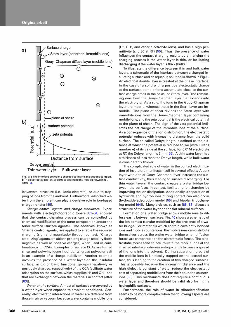
Fig. 9: aThe interfacebetweenachargedsolid andanaqueoussolution.bTheelectrostaticpotential corresponding to themodel shown in (a).After [55]
ical/crystal structure (i.e. ionic electrets), or due to trap-
ping of ions from the ambient. Furthermore, adsorbed wa-
ter from the ambient can play a decisive role in ion-based
charge transfer [55].
Charge control agents and charge stabilizers: Exper-
iments with electrophotographic toners [81–84] showed
that the contact charging process can be controlled by
chemical modification of the toner composition and/or the
toner surface (surface agents). The additives, known as
‘charge control agents’, are applied to enable the required
charging (sign and magnitude) through contact. ‘Charge
stabilizing’ agents are able to prolong charge stability (both
negative as well as positive charges) when used in com-
bination with CCAs. Examples of surface CCAs are fumed
silica and polyvinylidene fluoride, whereas polyester salt
is an example of a charge stabilizer. Another example
involves the presence of a water layer on the insulator
surface; acidic or basic functional groups (negatively or
positively charged, respectively) of the CCA facilitate water
adsorption on the surface, which supplies H+ and OH– ions
that are exchanged between the materials in contact (after
[83]).
Water on the surface: Almost all surfaces are covered by
a water layer when exposed to ambient conditions. Gen-
erally, electrostatic interactions in water are different from
those in air or vacuum because water contains mobile ions
(H+, OH–, and other electrolyte ions), and has a high per-
mittivity (εr ≅ 80 at RT) [55]. Thus, the presence of water
influences the contact charging results by enhancing the
charging process if the water layer is thin, or facilitating
discharging if the water layer is thick (bulk).
To illustrate the difference between thin and bulk water
layers, a schematic of the interface between a charged in-
sulating surface and an aqueous solution is shown in Fig. 9.
An electrical double layer is created at the phase interface.
In the case of a solid with a positive electrostatic charge
at the surface, some anions accumulate close to the sur-
face charge areas in the so called Stern layer. The remain-
ing ions form the Gouy–Chapman layer that extends into
the electrolyte. As a rule, the ions in the Gouy–Chapman
layer are mobile, whereas those in the Stern layer are im-
mobile. The plane of shear divides the Stern layer with
immobile ions from the Gouy–Chapman layer containing
mobile ions, and the zeta potential is the electrical potential
at the plane of shear. The sign of the zeta potential indi-
cates the net charge of the immobile ions at the surface.
As a consequence of the ion distribution, the electrostatic
potential reduces with increasing distance from the solid
surface. The so-called Debye length is defined as the dis-
tance at which the potential is reduced to 1/e (with Euler’s
number e) of its value at the surface; for 0.01M electrolyte
at RT, the Debye length is 3 nm [55]. A thin water layer has
a thickness of less than the Debye length, while bulk water
is considerably thicker.
The complicated role of water in the contact electrifica-
tion of insulators manifests itself in several effects: A bulk
layer with a thick Gouy–Chapman layer increases the sur-
face conductivity, thus leading to surface discharging. For
thin water layers, the contact creates a water bridge be-
tween the surfaces in contact, facilitating ion charging by
improving the ion dissipation. Additionally, a separation of
hydroxide and hydron ions during contact can also occur
(hydroxide adsorption model [55] and bipolar tribocharg-
ing model [64]). Many articles, such as [85, 86] discuss a
structure of the water layer on the flat mineral surfaces.
Formation of a water bridge allows mobile ions to dif-
fuse easily between surfaces. Fig. 10 shows a schematic of
the ion contact transfer modified by the presence of a wa-
ter bridge. For materials which contain covalently bonded
ions andmobile counterions, themobile ions can distribute
themselves across the entire water bridge when diffusion
forces are comparable to the electrostatic forces. The elec-
trostatic forces tend to accumulate the mobile ions at the
charged interface, whereas entropy tends to cause a spread
of the ions into the solvent. During separation, a part of
the mobile ions is kinetically trapped on the second sur-
face, thus leading to the creation of two charged surfaces.
This is possible because the increasing distance and the
high dielectric constant of water reduce the electrostatic
cost of separatingmobile ions from their bounded counter-
ions [55]. This mechanism does not require a continuous
water layer and therefore should be valid also for highly
hydrophilic surfaces.
Furthermore, the role of water in triboelectrification
seems to be more complex when the following aspects are
considered:
368 Mirkowska et al. © The Author(s) BHM, 161. Jg. (2016), Heft 8

Originalarbeit
Fig. 10: The roleofwater in theion-transfermechanismof tri-boelectrification for insulatorsthat contain covalentlyboundionsandmobile counterions.From[55]
Fig. 11: Hydroxideadsorptionmodel. aBeforecontactOH–
ionspreferentiallyaccumu-lateon the insulator surface,whereasH+ ionsremains in thesolvent. bDue to contact, awa-ter bridge is formedandOH–
ionsarecollectedmostlyonthesurfacewithhigher chemi-calaffinity. cSeparationresultsin twooppositely chargedsur-faces. From[55]
creation of a water hydrogen bonded network and the
auto-dissipation of water (creation of hydronium H3O+
and hydroxide OH– ions) [87],
influence of mechanical stress on water ionization [64],
different adsorption properties of water on different sur-
faces (e.g., on calcite [88], quartz [89], a comparison for
different minerals [85]),
increasing the effective area of contact due to formation
of a water bridge [55],
reduction of the water layer thickness and, simultane-
ously, decreasing water permittivity (due to higher ion
dissipation) with temperature,
influence of an external electric field on the surface wet-
tability [90],
presence of other ions (HCO3–, CO3
2–, Na+, Cl–) typically
dissolved in water [64].
It needs to be noted that the water layer present on the
surface may have an influence on the charging not only
by ion transfer but also by electron transfer. Water ions
can neutralize charge through screening or redistribution
of charges on an area bigger than the actual contact area.
Also, like other adsorbents, water ions change the elec-
tronic surface structure of the host insulator. Table 3 con-
tains the experimentally determined work functions of se-
lected minerals in dry and humid air [21].
Hydroxide adsorption model: Based on Diaz’s consider-
ations [91], their own works and extended literature analy-
sis, McCarty et al. [55] proposed the hydroxide ion trans-
fer mechanism (Fig. 11) which explains contact charging
of a non-ionic insulator with a water layer on its surface.
The model is based on the observation that hydroxide ions
(OH–) from the water preferentially accumulate in the im-
mobile Stern layer, leaving protons (H+) in the solution. It is
important to mention that the tendency to accumulate OH–
ions at the interface, although experimentally observed, is
not well understood.
During contact, when the water bridge is formed, hy-
droxide ions redistribute and stabilize on the insulator sur-
face with the greater chemical affinity, whereas H+ ions re-
main evenly spread in the solution. Finally, when surfaces
are separated, the material with more hydroxide ions ac-
quires a negative charge. And oppositely, thematerial with
lesser hydroxide ions on the surface shows a positive to-
tal charge, since protons predominate. Additionally, other
ions – present in the water layer – can also contribute to
the proposed process, which makes final results difficult to
predict.
However, by simple analogy, this model can be applied
toexplain thesuccessful triboelectrostatic separationof dif-
ferent minerals functionalized by the same additives (e.g.
conditioning of salts increases the efficiency of the tribo-
electrostatic separation [1, 2]).
Bipolar tribocharging model: An ion transport model
involving frictional forces, proposed by Knorr [64], is based
on two assumptions. Firstly, the hydroxide ions are more
BHM, 161. Jg. (2016), Heft 8 © The Author(s) Mirkowska et al. 369

Originalarbeit
Table 3
Work function for different minerals in dry and hu-mid air. From [21]
Mineral Work function (eV)
at humid air20 % r.H; 20 °C
at dry air2.5 % r.H; 30 °C
Fluorite 4.24 4.32
Calcite 4.26 4.41
Quartz 4.29 4.39
Barite 4.22 4.31
Pyrite 4.52 4.50
Galena 4.51 4.57
strongly bonded to the insulator surface than the pro-
tons. Secondly, the charge separation is driven by the
rubbing forces as suggested by the strong dependence of
tribocharging results on the rubbing load. Interestingly,
based on observations, the spontaneous dissociation of
bulk water is actually insufficient to provide a high enough
amount of OH– ions for the process. However, the dissocia-
tion ratemight be significantly enhanced in the presence of
a surface. When a capillarybridge is formed, the separation
of water ions occurs by preferential dragging of protons
in front of the moving asperity of one of the surfaces in
contact with the second. The hydroxide ions underneath
the asperity may be squeezed into the uppermost layers of
the surface or into abraded particles. As a result, bipolarly
charged surface is obtained; the positively charged area
is created by accumulation of protons, and the negatively
charged by depletion of protons.
Knorr [64] also suggested that the contact path of the
asperity is much shorter than the total path of rubbing.
This can explain the differently charged areas within the
charging surface. Moreover, the roughness of the surfaces
and the shape of the rubbing asperity have an impact on
the charging characteristics. Unfortunately, the bipolar tri-
bochargingmodel does not elucidate different values of net
contact charging acquired by different materials.
3.1.3 Mass Transport
Mass transport as a mechanism of charging is similar to
the processes in ion transport. The main difference lies
in the type of the charge carriers. Unlike in the case of ion
transport where charging occurs by the exchange of ionized
surface adsorbates, here, surface atoms of one body are
transferred onto the surface of the copartner body due to
contact.
Experiments by Baytekin et al. [92] showed that mate-
rial transfer depends on the mechanical properties of the
materials, such as hardness and cohesive energy. Harder
materials remove pieces of a softer surface, and materials
with higher cohesive energy are less susceptible to hav-
ing pieces ripped off. Also, the roughness of the material’s
surface can influence material transfer. Rough and smooth
samples of the samematerial can vary in their charging be-
havior [60]. A rough surface of a hard material is more ef-
fective at tearing (abrading) another surface than a smooth
surface of the same material. In some cases, exchange of
mass can be so strong that the initial properties ofmaterials
change dramatically up to the point of emulating charging
behavior of the counterpart materials [92, 93]. This is an in-
herent feature of charging by mass transport. Surprisingly,
Baytekin et al. [92] report exchange of atoms in both di-
rections. After bringing polydimethylsiloxane (PDMS) into
contactwithpolytetrafluoroethylene (PTFE), fluorine atoms
were found on the PDMS surface whereas silicon and oxide
atoms where detected on PTFE.
Moreover, material transfer strongly depends on the
mode of contact, whereby normal and shear contact forces
differ in their effect from each other [94]. Recent results
[92, 93] indicate that material transfer is more significant
in some types of contact electrification. In this concept,
authors hypothesized that mass transport is supported by
the presence of air or water molecules on the insulator
surface. These adsorbents cause local heterolysis of the
surface material. This is the cleavage of chemical bonds of
a neutral molecule which generates a cation and an anion,
i.e. or . The created
ions are weakly bound and mass-charge transport can
occur due to contact with other objects.
Moreover, Lacks [94] suggested that the very contact
leads to material transfer which causes surface contami-
nation that can never be avoided in contact charging ex-
periments. However, it is difficult to establish whether this
mass transfer is the primary cause of the charge separation
or simply a side effect.
Lowell and Rose-Innes [60] argue that charge transfer
occurs due to electron transport and ions present on the
surface. Material exchange during contact only influences
the electronic structure of the insulator and therefore en-
hances or reduces the amount of electrons which can be
available during triboelectrification.
Finally, based ondensity functional theory (DTF) calcula-
tions for polymericmaterials, Sakaguchi et al. [95] propose
that charge transfer is simply a combination of electron,
ion andmass transport. The frictional contact between two
polymeric materials induces macroscopic andmicroscopic
fracture of material (mass transport). This results in the
creation of mechano ions (ion transport) which change the
energetic structure of the materials in contact and thus fa-
cilitate electron transport.
Mosaic charge model – ion/mass transport: The mosaic
charge model [92] describes the evolution of a net charge
on insulating surfaces due to a light contact. Chargingman-
ifests itself as a random network (“mosaic”) of nanoscopic
regionswithopposite charges (positive andnegative polar-
ity). The mosaic can accommodate a significant amount of
charge per unit area, but the total charge on the electrified
surface remains relatively low due to the compensation be-
tweencharged regionsof different polarities. Moreover, the
charging process is accompanied by changes in the surface
composition. Therefore, contact chargingproperties canbe
derived from the chemical andmicromechanical properties
at and near the involved surfaces. Furthermore, material
transport can occur during contact and can even play a role
in the charging process.
370 Mirkowska et al. © The Author(s) BHM, 161. Jg. (2016), Heft 8

Originalarbeit
Fig. 12: aSchemeof themo-saic chargemodel. Uponcon-tact charging, the regionswithdifferent chargepolaritiesaredevelopedon thecontact area.bAsetof typicalKPFMscansofsurfacepotential ofPDMS(A)beforeand (B,C)after contact.Themap in (B), corresponds toPDMSsurfacepotential afterchargingPDMSagainstPDMS,and in (C), toPDMSsurfacepo-tential after PDMSagainstPCcontact, featuringamosaicof(+) and (–) regions. From[92]
In Fig. 12a, a schematic of the charging process accord-
ing to the mosaic charging model is presented. Due to the
light contact (touching), a mosaic charge structure is cre-
ated on the surface of two neutral insulators with alternat-
ing positive and negative regions within the contact area.
Kelvin probe force microscopy (KPFM) [96] measurements
(Fig. 12b) reveal two characteristic length scales of the mo-
saic structure that can be distinguished: (a) bigger regions
with diameters of several hundreds of nanometers, and (b)
smaller regions, inside bigger ones, with a diameter of tens
of nanometers.
In summary, as shown above, there is no consensus
on the tribocharging mechanism. However, it is obvious
that the insulator charging behavior is determined by the
surface properties of the materials in contact. And also,
the complex charging behavior indicates that more than
one mechanism is active. (Nonetheless, creation of a tri-
bocharging model post factum, i.e. based on experimental
observations, does not guarantee that a universal model,
properly applicable to industrial applications, can ever be
built.)
3.2 Contact of Two Bodies
3.2.1 Non-frictional and Frictional Contact
Dependingon thebehavior of thechargingmaterials, a con-
tact which causes charging is categorized as (light) touch-
ing, rubbing, rolling, sliding, bouncing, or impact contact.
Generally, contacts can be divided into two types, i.e. non-
frictional and frictional. In the case of non-frictional contact,
the contact force is purely normal to the contact interface.
On the contrary, in frictional contacts, in addition to the nor-
mal force, lateral shear and frictional forces also act. Apart
from thenon-frictional contact of twosmooth surfaces, fric-
tional contact is a highly non-equilibrium situation [97].
Also, other distinctions for the contact can be made, as
follow:
contact without mechanical deformation vs. contact
with elastic or plastic deformation,
contact of smooth surfaces vs. multipleasperity contact.
Hertzian contact: Hertzian contact [98, 99] is the classical
model to describe the contact of two solids. The Hertzian
contact model defines a static, point or linear, and non-fric-
tional contact between two homogenous, smooth bodies
at rest and in equilibrium [99]. Rolling and sliding can also
be considered as a sequence of consecutive static point
contacts (but not in equilibrium). In Fig. 13, stresses which
appear during a Hertzian contact of two bodies at a smooth
interface are illustrated.
Under a static load and without a relative movement
between the bodies, shearing does not occur. If the con-
tact load is sufficiently high, i.e. in the elastic deformation
regime, the material slips along the line of action of maxi-
mum shear stress, which is at 45° to the plane on which the
shear stress is zero (the principal plane). Further increase in
the load leads to plastic deformation [99] under the surface
of the material. Interestingly, the maximum shear stress
also occurs at the same depth as the maximum depth of
the plastic deformation for a given load and this value is re-
lated to the contact area (theHertzian stress field – Fig. 14a).
In a circular static contact, for instance, themaximumshear
stress occurs at a depth of approximately 0.6 times the ra-
dius of the contact area [99]. Thismayhave implications for
tribocharging mechanisms, in terms of an active region of
charging which comprises of the contact area at the surface
and the “active depth” of contact.
BHM, 161. Jg. (2016), Heft 8 © The Author(s) Mirkowska et al. 371

Originalarbeit
Fig. 13: StressesduringHertzian contact: astatic andb sliding; σ1, σ3 arethemainstresses,pisthehydrostaticpressure,k–theshearyieldstressofthematerial, μ –thecoefficientof friction,q–thestressnormalto theinter-faceorcompressivestressduetoload,φ–theanglebywhichtheprincipalplanesare rotated fromthecorresponding zero frictionpositions tobal-ance the frictional stress. From[99]
For rolling or sliding, additional shear stress acts at the
contact interface due to the frictional forces. Moreover, the
contact area increases during frictional contacts as com-
pared to static contacts and the additional shear modifies
the Hertzian stress field (Fig. 14b). This can be the origin of
the frequently observed higher tribocharging efficiency of
frictional contacts compared to non-frictional contacts.
3.2.2 Mechanical Deformation Due to Contact
Mechanical deformation may occur under compressive
stresses, caused by the contact load, and result in a re-
arrangement of the object atoms [100]. The interlayer
spacing of the atoms are reduced along the direction of the
contact load and expanded in the other directions. Chang-
ing the lattice parameters of the crystal unit cell alters the
electronic properties of the deformed area of the object,
such as band gap, work function and surface conductance,
etc. Thus, the magnitude of the transferred charge may
increase with deformation, as it was shown by Zhang and
Shao [101] for metals. Their calculations based on density
functional theory (DFT) indicate that the crystal deforma-
tion causes an increase in the concentration of nearly free
electrons andadecrease in the energybarrier for the charge
transfer. Thus, mechanical deformation promotes electron
transfer during contact. Moreover, according to Zhang and
Shao [101], the “classical” model of metal tribocharging
based on work function differences can only be applied to
very light contacts (contact without deformation).
It seems that the differences in tribocharging with re-
spect to elastic and plastic contact deformation can just
be attributed to the number of the introduced structural
changes in thematerial and the durability of these changes.
It will also be interesting to compare the tribocharging abil-
ities of textured and undeformed materials.
3.2.3 Multi-asperity Contact
Surface roughness limits the contact between bodies to
small areas of true contact between the highest spots of
the surfaces – a multi-asperity contact. There are several
differences between the contacts through asperities and
the contact of flat surfaces. Firstly, the contact path of the
asperity may be much shorter than the total path of rub-
bing [64]. Thus, the true contact area may be very different
from the macroscopic contact area. Secondly, the contact
pressure ismuch higher than that calculated by simple divi-
sion of the contact load by the total contact area, which can
cause stronger deformation of the asperities (flattening) in
softer material than expected [77, 99]. Thirdly, the electric
field is enhanced at the asperities. Thus, a stronger charg-
ing might occur as described above [101]. Usually, after an
initial plastic deformation, the asperities keep their shape.
Therefore, the contact between them occurs mostly in an
elastic regime [99].
The local contact pressure between asperities which are
constantly coming in and out of contact during shearing
can vary significantly. According to Urbakh [97], the value
fluctuatesbetween1Paand1GPawithinmicrosecondsand
depends only [99] on the Young’s modulus of thematerials
and the asperity geometry.
There are several models describing multi-asperity con-
tacts based on both statistical methods and fractal geome-
try. An overview is given in [99].
3.2.4 Friction, Adhesion and Wear
Friction, adhesion and wear are strongly correlated with
each other. Wear can be considered as mass transport and
will not be taken into account here. However, local adhe-
sion can be a reason for stick-and-slip contact of twobodies
in relative motion [97]. Fig. 15 shows schematically areas
of local adhesion during the contact of two rough surfaces.
In the stick–slip motion, adhering areas are successively
formed and broken, which is the reason for the discontinu-
ousmovement of twobodies in frictional contact. Stick–slip
processes are observed for even very low friction forces
[99] and a general relation between the driving velocity
and the height of stick–slip spikes (the frequency and the
occurrence time) was found [97].
During contact, adhesion of two dissimilar materials in
dry atmosphere ismuchhigher than the adhesion of similar
materials. A change of humidity can modify the interaction
of the surfaces. This is due to the formation of a water layer
whichmodifies the adhesion and friction. Furthermore, the
shear stress decreases dramaticallywith increasing humid-
ity [102]. This alteration in themechanics of contact can be,
besides increasing the number of mobile ions on the sur-
face, another reason for the different tribocharging behav-
ior observed in the presence of awater layer on the surface.
The contact theories developed by Johnson, Kendall,
and Roberts (JKR theory) and Derjaguin, Muller, and
Toporov (DMT theory) adapt the Hertzian theory by in-
cluding adhesive forces and elastic deformation which
occur during contact between two smooth surfaces (after
[102]). JKR theory is usually applied to high adhesion
372 Mirkowska et al. © The Author(s) BHM, 161. Jg. (2016), Heft 8

Originalarbeit
Fig. 14: Subsurfacestressfieldforastatic contactof twocylin-ders, andb slidingofacylinderonaplane;b is thehalfwidthofthecontact area. From[103]
Fig. 15: Schematicof local ad-hesionduring contactof tworoughbodies. From[99]
and large radii of contact, whereas DMT theory is used
to describe systems with low adhesion and small radii of
contact. None of the theories take into account the long-
range electrostatic interactions which occur during contact
electrification [102].
Friction, defined as the dissipation of energy between
sliding bodies, obeys two empirical rules: There is propor-
tionality between the maximum tangential force and the
normal force and the frictional forces do not depend on the
contact area and the sliding speed [99].
3.2.5 Differences Between Static and Sliding
(Dynamic) Contacts
It is believed that the fundamental differences in structure
and physical processes occur for static and sliding contacts
[99].
A static contact between rough surfaces can be seen as
a random distribution of point contacts. For sliding con-
tacts, contact areas are larger and less numerous (Fig. 16).
If surfaces are in motion, the distance between individual
contact points is larger than in the static contact. Only the
larger asperities survive mechanically during sliding and
additionally their areas in contact increase due to themove-
ment [99]. Therefore, despite of the same total load and
number of asperities, the local contact pressure for a single
BHM, 161. Jg. (2016), Heft 8 © The Author(s) Mirkowska et al. 373

Originalarbeit
Fig. 16: Acomparisonbetweenastatic contact andb sliding. From[99]
asperity candiffer betweenstatic andslidingcontacts. Thus
static and sliding contacts can behave quite differently.
The latter considerations show that the final result of tri-
bocharging does not only depend on the electronic struc-
ture of the materials and the presence of ions on the sur-
faces, but also depends on surface roughness andmechan-
ical properties of the materials in contact. Especially the
contact through asperities is themost probable type of con-
tact [103], since all surfaces exhibit some roughness.
3.3 Further Considerations
A collection of factors which have an impact on triboelec-
trification has already been listed in Table 1. Those factors
involve a set of basic physical and chemical material prop-
erties and the influence of environmental conditions. The
most important factors are described in more detail below.
3.3.1 Influence of Pretreatment – Surface
Modification
Since surface impurities or defects in the crystal lattice in-
fluence the electronic surface states, any surface treatment
can change the ability of a material for contact charging
[104]. Fig. 17 illustrates the impact of different grinding
procedures and radiation treatment on the position of the
Fermi level (effective work function) of calcite.
In a mill the mineral grains are continuously crushed
and nascent and highly reactive surfaces are exposed to
the ambient grinding atmosphere. The effect of wet or
dry comminution on the calcite Fermi level is shown in
Fig. 17a. Calcite behaves as an n-type semiconductor when
wet-ground, and as a p-type when dry-ground. Also X-ray
radiation (Fig. 17b) causes a shift in the Fermi level with
respect to the natural mineral. Thus calcite turns from be-
ing an n-type semiconductor in its natural mineral state to
p-type semiconductor after irradiation.
Additionally, Lindley and Rowson [105] report that com-
minution produces charges on the surface of the crystals
both with and without cleavage planes. For example, on
a quartz (the crystal without cleavage planes) surface a
continuous array of charges exists. “A positive charge is
linked with the electropositive atom (silicon) and a nega-
tive chargewith the electronegative atom (oxygen) for each
rupture site”. For materials with natural cleavage planes,
each face opened by grinding or crushing can vary in the
number of ions, which influences the surface charge. Also,
performing comminution in moist air leads to adsorption
of water molecules on the fracture surfaces. Those water
molecules ionize and thus surface charging by ion transport
and/or ion segregation can occur.
3.3.2 Discharging, Decay and Evolution of the
Introduced Charge
In principle, the contact charging process can be divided
into a charging and a discharging step [106]. First, during
the contact, charge transfer takes place (charging). There-
upon, during separation, tunneling of electrons, field emis-
sion of electrons, anddielectric breakdownof the surround-
ing gas lead to charge recombination and partial discharge
of the surface. Additionally, charged objects can be dis-
charged during the next contact [107]. Finally, the charge
remaining on the surface decays slowly. In the following,
phenomena such as (i) dielectric breakdown of the gas en-
vironment, (ii) discharge during separation caused by the
electric field created between charged surfaces, (iii) accu-
mulation and saturation of the charges on the insulator sur-
face by repetitive charging of the same area, and (iv) long-
term charge decay on the insulator surface are described
briefly.
Dielectric breakdown of the gas environments: The
density of charge locally stored on the insulator surface is
limited due to the dielectric breakdown in the atmosphere.
Paschen’s law [108] defines the breakdown limit as the
potential V between electrodes placed against each other
under specific environmental conditions at which electric
breakdown occurs (density of gas molecules, which de-
pends on type of atmosphere, atmospheric pressure p and
temperature, etc.) and is given by Eq. 6:
V =a(pd)
ln (pd) + b(6)
374 Mirkowska et al. © The Author(s) BHM, 161. Jg. (2016), Heft 8

Originalarbeit
Fig. 17: PositionofFermi level asa functionof temperature for calciteatdifferentagrinding,andbX-rayirradiation(wavelengthλwas2.29Å)con-ditions. From[104]
Fig. 18: Schematicof theseparationdischargeprocess. Paschen’sbreak-downcurvedependsonelectricfield anddistancebetween twoelec-trodesor chargedobjectsunder specificenvironmental conditions. After[109]
Here d is the distance between the electrodes and a, b
are constants which depend on the atmosphere and the
electrode material [109, 110].
Charge carriers are accelerated in the electric field be-
tween the electrodes. If the carriers gain sufficient kinetic
energy to create further electrons and ions upon collision
with gasmolecules, the number of free charge carriersmul-
tiplies causing an avalanche ionization of the surrounding
which is discharging the objects. The sharp rise in the
breakdown voltage on the left side in Fig. 18 (red line) oc-
curs as the electrode spacing is too small for ionization.
(However, it is known that Paschen’s law fails at microme-
ter distances due to electron field emission, which results in
the creation ofmodified Paschen’s curves [111, 112].) On the
right side the slow rise in breakdown voltage with increas-
ing electrode distance (and/or higher pressures) arises be-
cause charge carriers cannot gain enough energy between
generation and collision to cause impact ionization. Thus
high potentials are needed for breakdown [110].
For breakdown at the microscale [112] field emission
might serve as a significant source of free electrons and
causes discharging and charge recombination between
charged bodies.
Matsuyama and Yamamoto [106, 109] proposed that the
limitation of contact charging is caused due to discharging
during separation (Fig. 18). After contact the potential be-
tween highly charged particles increases with increasing
distance until it reaches the left side of the minimum in the
Paschen’s discharge curve (beginning point of charge relax-
ation). This discharge lowers the charge of the particles to
the level which corresponds to the terminal point of charge
relaxation on the Paschen’s curve.
Discharge during separation of charged bodies: Dis-
charge between contact charged bodies is often observed
as they are separated [107, 109, 113] and is associated with
both tunneling back-flow of charge carriers [55, 60] and
breakdown in the atmosphere [55, 113] due to the electric
field existing between charged bodies. In the separation
process, the potential difference between the charged sur-
faces increases with increasing distance between them to
eventually reach a value for the atmospheric breakdown
limit. However, before breakdown is reached, charge back-
flow can occur by tunneling. Back-flow by tunneling is a
quantum mechanical effect and is practically restricted to
small distances between surfaces (less than a few nanome-
ters).
Charge accumulation and saturation by repetitive
charging: First Matsuyama and Yamamoto [109] and then
Ireland [113] identified the experimentally observed charge
accumulation and saturation effects to be a result of sepa-
ration discharging. They distinguished two possible cases
(Fig. 19). In the first case the saturation is reached after a
certain number of contacts (discharge limit). After that the
discharge during every next separation event limits further
building up of charge (Fig. 19a). In the second case sin-
gle discharging events reduce the formerly accumulated
charge to such an extent that several contact – separa-
tion cycles are necessary to reach the discharge limit again
(Fig. 19b). In this case, the charge oscillates between amax-
BHM, 161. Jg. (2016), Heft 8 © The Author(s) Mirkowska et al. 375

Originalarbeit
Fig. 19: Separationdischargescheme: aafter reaching thedischargelimit, dischargeoccursduringeveryseparation compensatingan in-creaseof contact charge [109] (experimentallyobservedasasaturation),b chargebuildsupover several contact – separation cyclesbeforedis-chargeoccurs [113] (experimentallyobservedasdroppingandbuildingupchargedue to repetitivecontactwith thesamearea)
imum value, the discharge limit, and aminimum value, the
extinction limit.
Long-term decay of charged insulators: A comparison
of the temporal decay of contact charge on a polymer sur-
face in humid air (relative humidity 40 % r.H.) and in wa-
ter-free environment (in paraffin oil) [114] showed that the
decay kinetics is of first-order, and that the corresponding
chargedecay ratesvarywithenvironmental conditions (10-3
s-1 and 10-2 s-1 in air and oil, respectively). This suggests
that the charge decay is associated with a different stabil-
ity of the introduced charges under humid air and paraffin
oil. Anothermodel assumes impingement of the surround-
ing molecules onto the charged surface as a way of charge
neutralization. The probability of collisions with the liquid
molecules is much higher than with the molecules/ions of
the air (about 3 x 10²¹ molecules per cm3 in paraffin oil and
2 x 10¹⁹ in air). Thus, the charge can be transferred more
readily to the liquid. The experimentally observed com-
plete discharge of a moving sample within 1 s supports the
later model.
3.3.3 Bipolar Charge Distribution of Granular
Materials with Different Grain Size
In a polydisperse powder of the same material, the trans-
ferred charge depends on the particle size [115, 116]. After
contact of two particles of different size (but same mate-
rial), it is experimentally observed that the smaller will be
charged negatively whereas the bigger one exhibits a pos-
itive net charge.
Several contrary ideas have been discussed in literature
to explain this phenomenon [46, 64, 80, 115, 117]. Inculet
et al. [115] imply that there are differences in the effective
work functions between fine and coarse particles, which
can be caused by differences in their surface energy, mi-
croscopic surface structure and/or selective adsorption on
the surface. Moreover, the work function is generally as-
sumed to be inversely proportional to the particle size [118,
119]. Thus, more energy is required to extract an electron
from the surface of a small particle than from a larger one.
Optionally, as a result of repetitive fracturing or grinding,
the fine particles are usually more subjected to mechanical
treatment than the coarser ones. This yields differences
in shape and surface roughness, which also can be related
to changes of the effective work function. Finally, adsor-
bents or additives have usually higher surface densities on
finer particles as the surface energy increases withdecreas-
ing particle size [115]. Therefore, adsorbed air ions, for in-
stance, can change the value of the effective work function
of the finer particlesmore strongly compared to the coarser
ones.
Asymmetrical contact between particles of different size
is also considered as origin of bipolar charge distribution.
Asymmetrical contact can either mean the asymmetrical
transfer of electrons [46, 117] or size dependent differences
in the number of repeated contacts [80].
The larger particles have a larger number of electrons to
transfer, so compared to the smaller particles they aremore
likely to lose electrons as multiple collisions occur. There-
fore they charge positively. During initial collisions both
small and large particles drop similar amounts of electrons;
however, lost electrons remain a larger part of all available
electrons for smaller particles. Thus the loss of electrons
at further collisions is reduced for smaller particles as com-
pared to larger particles, which effects in final diversifica-
tion of charge between larger positively and smaller nega-
tively charged particles [46]. A model of asymmetrical in-
transferred electrons for a granular system of identical in-
sulators was proposed by Kok and Lacks [46]. It was further
extended by Zheng et al. [117] to account for the influence
of a water layer.
Contrarily, Gu et al. [80] suggest that the difference in
charging occurs as the probability of repeated collisions at
the same contact area is higher for finer particles. This is
owing to the difference in the surface areas, whereby the
same part of the small particle surface is brought into con-
tact more often than that of a bigger particle. As a result of
intensive friction, the temperature of finer grains increases
faster, which in turn has an influence on the concentration
of OH– and H+ ions. Hydroxide ions are trapped on the sur-
376 Mirkowska et al. © The Author(s) BHM, 161. Jg. (2016), Heft 8

Originalarbeit
Fig. 20: Schematicoftriboemission[125],whichinvolvesemissionofpar-ticles (gasatoms, surfacemolecules,molecular clusters, ions, radicals,electrons)andenergy (electromagnetic radiation,magnetic andelectricfield,heat, soundandvibrations) [124]
face of the finer particles, while hydroxyl ions transfer due
to contact onto the surface of coarser particles.
Finally, both the coexistence of nano- and micro-bipo-
lar areas on flat charged insulators [64, 120, 121], and the
opposite charging of small and large particles can be ex-
plained by the bipolar tribocharging model [64]. The fine
grain in contact with the coarse grain acts as the appendix
which collects the hydroxide ions and leaves the dragged
protons on the surface of the large object.
3.3.4 Other Influences
Electric permittivity: It should be mentioned that in earlier
publications differences in the electric permittivity were
also discussed as a driving force of triboelectrification.
However, due to large scattering of the measured values
of electric permittivity [20], a definitive statement on the
influence of permittivity is still missing.
Saturation effect: Thewell-knownsaturationeffect, orig-
inally defined as limited accumulation of charge on the sur-
face [47], can also be caused by:
gradual charging of different parts of the particle surface
with increasing number of contacts [122],
nano-mass transport when each contact causes ex-
change of atoms between the two bodies, up to a certain
level of mass transport when the top layer of the surface
shows different electric properties compared to the rest
of the body [92, 93],
complicated interaction between neutral and partially
charged particles, which can be described as fluctuation
of an external electric field [123],
discharging during separation (as already mentioned
earlier).
Surface behavior under mechanical stress: Another im-
portant phenomenon which can impact on tribocharging
results, is the mechanoemission of ions, low-energy elec-
trons, etc. (Fig. 20). Electrons with energies typically be-
tween 1 and 4 eV are emitted from the insulating surface
by chemical bond scission (during contact) and rapidly re-
act with the surface material to form free radicals and ions
[124]. Thus, the rubbed surface is highly reactive. With
higher contact loads (∼1 N or more ) a higher degree of
surface damage will occur and thus the quantity of emit-
ted charge carriers increases [125]. Nakayama and Martin
[100] even observed the creation of a triboplasma due to
the sliding of a diamond sphere with a radius of 0.3 mm
on a sapphire disc. The normal force was 0.9 N, while the
sliding velocity was 30 cm/s at 30–40 % r.H., which are con-
ditions that can essentially occur in technical separators.
The existence of a triboplasma is accompanied by an in-
creasing chemical reactivity of the surface. An example of
a dry tribochemical reaction is the creation of thin lamel-
lar graphitic structures on silicon carbide surfaces sliding
against each other in ultra-high vacuum [100]. The authors
suggest that the top layers of the silicon carbide transforms
into graphite due to friction induced evaporation of silicon
atoms.
Mechanoemission implies that ion, electron and mass
transport can occur during contact. Moreover, mechanical
forces intensify the dissociation of adsorbedwater. Accord-
ing to simulations, adsorbed water may enhance the het-
erolytic mechanical breaking of chemical bonds at the sur-
face [64]. The rapid point increase of the temperature due
to rubbing (flash temperature) [124] might also play a role
in the resulting tribocharge. Therefore mechanochemistry
and especially tribochemistry should alsobe considered for
a general description of tribocharging.
4. Experiments of Triboelectrification
4.1 Triboelectrification at the Macroscale
Knowledge of the triboelectrostatic separation behavior of
a particular system of insulating powders/particles is de-
rived from empirical studies, mostly based on trial-and-
error experiments. The lack of a comprehensive model is
attributed to the complexity of the tribocharging process
and the variety of basic phenomena which facilitate tribo-
electrostatic separation.
Triboelectric series: The first triboelectric series was de-
termined experimentally by Shaw in 1917 (after [126]). He
rubbed various materials together and used an electro-
scope to measure the charge on their surfaces. The em-
pirical “triboelectric series” is simply a rowwhich arranges
materials according to their ability to gain/acquire a nega-
tive or a positive charge due to contact. And thus it helps
to predict charging behavior of materials since the relative
position of any two materials in the series determines the
direction of charge transferwhen thesematerials come into
contact. However, the concept of the triboelectric series,
although technically useful, is challenged by the existence
of a cyclic triboelectric series [55]. Additionally, the order
in the triboelectric series is not always reproducible and
there exist several variants of the triboelectric series with
different material orderings, since many additional factors
influence the triboelectrificationprocess (as shown earlier).
Charging of a single particle: The tribocharging behav-
ior of a single particle is the basis for understanding the
charging of powders [54]. For this purpose, investigations
of the changes in the surface charge for single particles
BHM, 161. Jg. (2016), Heft 8 © The Author(s) Mirkowska et al. 377

Originalarbeit
caused by a collision with a still target were performed.
Several studies have been reported, a few among the
newest can be found in [61, 78, 127, 128]. A particle is ac-
celerated, which then collides with a target in a collection
chamber. The charge on the particle is measured before
and after impact using a Faraday cage.
Watanabe et al. [127] showed that the impact charge in-
creases with the impact velocity. Additionally, Ema et al.
[128] studied the influence of the impact angle on the tribo-
electric charging upon the contact of a particle stream with
rotating or inclined target system. The results suggest that
the contact charge depends on the effective contact area.
Also the results presented in [127] confirm that increasing
the contact area and the impact angle increases the im-
pact charge. Moreover, an initial charge (before contact)
of the particle and its distribution on the particle surface
influences the final charge after contact [61].
Repetitive contact: Another important group of experi-
ments focuseson the influenceof repetitive contacts, which
are expected to occur typically during contact charging of
powders [49, 65, 78, 93].
Matsusaka et al. [78], for instance, measured the influ-
ence of repetitive contacts of a rubber sphere with a metal
plate. The results indicate an accumulation – saturation
mechanism. They also showed that the impact velocity de-
termines the contact area which in turn can influence the
resulting charge due to contact repetition. Ciccu et al. [49]
investigated the accumulation – saturation process for sin-
gle grains of different minerals (coal, limestone) by chang-
ing time and type of contact with the steel walls of a tri-
bochargingunit. Nosimple relationshipof thechargingasa
function of energy added to the systemwasobserved. For a
given experimental time, the introduced charge was higher
in the case of lighter contacts (sliding vs. rubbing). The au-
thors related this observationmainly to the short timeof ex-
periments (maximum 160 s), which showed only the early
stage of accumulation anddidnot allow to reach saturation.
Kwetkus and Sattler [65] studied repetitive charging of dif-
ferent systems such as particles of quartz, calcite, graphite
particles, teflon, etc. with a metal plate (aluminum, nickel,
copper, gold) in vacuum. These systems showed accu-
mulation and saturation effects depending on the number
of contacts. However, further investigations revealed that
the sign of the charge can change with increasing num-
ber of contacts. For example, when calcite particles are
brought into contact with a copper plate, initially they are
charged negatively, and after about 25 charging cycles they
become positively charged. Also quartz particles in contact
with a copper plate charge negatively during the first 150
charging cycles and beyond that showed a positive total
surface charge. As shown by X-ray fluorescence analysis,
this behavior can be explained by material transfer since
copper, a soft material, is abraded due to contact with the
relatively hard calcite and quartz particles. Similar charge
reversal due to material transport was recently reported by
Baytekin et al. [93] for contact between two insulators in
air. Teflon beads were rolled in a polystyrene dish. After
about a minute, the Teflon beads charged negatively, how-
ever, if rolling was continued for more than a fewminutes,
the Teflon beads charged positively. Independently, Ra-
man spectroscopy and X-ray photoelectron spectroscopy
confirmed the mass transfer.
Charging of powders: Thereareat least threemain types
ofmethodsused tomeasure tribochargingof powders. The
first one involves using a real or a laboratory triboelectro-
static free-fall separation systemwithmany collecting bins.
Mass and chemical analysis of the product from each col-
lecting bin combined with a selection of the process pa-
rameters allows finding the best separation procedure for
a chosen mineral system. Sometimes, the collecting bins
are Faraday cups which measure the total charge for each
product, and thus the specific charge can be determined.
However, thesemeasurementshave tobe repeated for each
powder compositionandeachcharging–separationset-up;
therefore they are time consuming and are actually more
useful for analyzing the separation equipment than for the
characterization of the tribocharging behavior of the pow-
ders. Exemplary applications of this type of method are
presented in [8, 32, 52, 129].
The second technique used to characterize the tri-
bocharging of particles is to measure the specific charge of
powders of only one material with a Faraday cage. Charg-
ing is realized in different triboelectrostatic charging units,
for instance by sliding particles on a plate [48], on a rotating
drum [28, 42, 57], or a cyclone [59], etc. A prime disadvan-
tage of the latter method lies in the weak predicting value
of the behavior of powder mixtures. It is caused by the
fact that charging occurs not only due to contact with the
charger walls but also due to contact between the particles.
The third group of methods is dedicated to determine
the charge distribution in powders [54]. Tribocharged par-
ticles are dragged by a laminar air flow between parallel
electrodes of opposite electrical potential. The position
where they are deposited on the electrode walls indicates
the charge distribution and the amount of charge in the
powder. An interesting review of further measurement
techniques for powder systems can be found in.[54].
4.2 Triboelectrification by Atomic Force
Microscopy
Measuring triboelectrification charge using classic macro-
scalemethods is not appropriate to explore single charging
events since they just deliver average values over large ar-
eas. As an alternative, measuring at micro- and nanoscale
can be applied. Themain advantages of studying triboelec-
trification phenomena at themicroscale are: (i) information
from very small areas is provided, (ii) the system can be
simplified to the maximum extent, thus giving scope for
investigating influences separately. These features present
an opportunity todescribe complex tribocharging phenom-
ena and, finally, to build a comprehensive model of tribo-
electrification.
The development of AFM by Binning and Quate [130],
followed by the introduction of a vibrating cantilever tech-
nique (non-contactmode)with the light-lever read out tech-
nique by Martin et al. [131] and finally the elaboration of
KPFM by Nonnenmacher et al. [96] allow to study electro-
static interactions on very small scale and thus triboelectri-
378 Mirkowska et al. © The Author(s) BHM, 161. Jg. (2016), Heft 8

Originalarbeit
fication phenomena at the microscale. Especially over the
recent few years, several publications [120, 121, 132–143]
dealt with the local triboelectrification on thin insulating
layers. Hence there is a need for a review article solely
dedicated to this topic.
5. Summary
In this article triboelectrification phenomena that occur
during the industrially applied triboelectrostatic separation
have been briefly reviewed. It has been shown that for
good separation results a precise adjustment of a number
of system parameters is necessary. Mechanic and electrical
properties of the powder have to be considered as well as
the properties of the charging unit, the type of separator
and environmental conditions.
Special attention has been payed to the contact charging
of solids, because the controlled generation and conserva-
tion of charge on the powder particles is themost important
factor for a successful separation.
We hope that we could show that contact charging
and triboelectrification is a very complex topic that so
far is not well understood. In order to push forward the
technological application of the conceptually cheap and
environmentally friendly method, a deeper understanding
of the basic physical mechanisms is inevitable. Therefore,
research on the basic processes involved in tribocharging
has to be intensified in the future.
Open access funding provided by Montanuniversität
Leoben.
Open Access This article is distributedunder the terms of the Creative CommonsAttribution 4.0 International License (http://creativecommons.org/licenses/by/4.0/), which permits unrestricteduse, distribution, and reproduction in anymedium,provided yougive appropriate credit to the original author(s) and the source,providea link to theCreativeCommons license, and indicate if changesweremade.
References
1. Fricke, G.: Die elektrostatische Aufbereitung von Kalirohsalzen, Kali
Steinsalz, 7 (1979) pp. 492–497
2. Fricke, G.: Die elektrostatische Aufbereitung von Kalium- und Mag-
nesiumsalzen, Kali Steinsalz, 9 (1986) pp. 287–294
3. Singewald, A.; Fricke, G.: Die elektrostatische Aufbereitung von
Kali-Rohsalzen, Chem. Ing. Tech., 55 (1083) pp. 39–45
4. Bittner, J. D.; Gasiorowski, S. A.; Hrach, F.J.; Lewandowski, W.;
Guicherd, H.: Triboelectric belt separator for beneficiation of fine
minerals, in Proc. of the 13th European Symposium on Comminu-
tion and Classification, Sierke Verlag, Göttingen, 2013, pp. 72–75
5. Peretti, P.; Serci, A.; Zucca, A.: Electrostatic K-feldspar/Na-feldspar
and feldspar/quartz separation: influence of feldspar composition,
Mineral Processing & Extractive Metall. Rev., 33 (2012) pp. 220–231
6. Bada, S. O.; Tao, D.; Honaker, R. Q.; Falcon, L. M.; Falcon, R. M. S.:
A study of rotary tribo-electrostatic separation of South African fine
coal, Int. J. Coal Prep. Util., 30 (2010) pp. 154–172
7. Inculet, I. I.; Castle, G. S. P.; Brown, J. D.: Electrostatic separation of
plastics for recycling,“ Part. Sci. Technol., 16 (1998) pp. 91–100
8. Dodbiba, G.; Shibayama, A.; Miyazaki, T.; Fujita, T.: Electrostatic
separation of the shredded plastic mixtures using a tribo-cyclone,
Mag. Electr. Separ., 11 (2002) pp. 63–92
9. Crook, T.: The electrostatic separation of minerals, Mineral. Mag.,
15 (1909) pp. 260–264
10. Crook, T.: Further remarks on the electrostatic separation of miner-
als, Mineral. Mag., 16 (1911), pp. 109–111
11. Dwari, R. K; Hanumantha Rao, K.: Non-coking coal preparation by
novel tribo-electrostatic method, Fuel, 87 (2008) pp. 3562–3571
12. Wu, G.; Li, J.; Xu, Z.: Triboelectrostatic separation for granular plas-
tic waste recycling: a review, Waste Management, 33 (2013) pp.
585–597
13. Flachberger, H.; Mirkowska, M.; Oberrauner, A.; Geissler, T.; Kratzer,
M.; Teichert, C.: Electrostatic separation in mineral processing – in-
ventory, challenges and outlook, in Proc. of the European Mineral
Resources Conference 2012, Wien, 2013, pp. 349–369
14. Kwetkus, B. A.: Particle triboelectrification and its use in the elec-
trostatic separation process, Particul. Sci. Technol., 16 (1998) pp.
55–68
15. Kelly E. G.; Spottiswood, D. J.: The theory of electrostatic separa-
tion: a review. Part I. Fundamentals, Minerals Eng., 2 (1989) pp.
33–46
16. Kelly, E. G.; Spottiswood, D. J.: The theory of electrostatic separa-
tions: a review. Part II. Particle charging, Minerals Eng., 2 (1989) pp.
193–205
17. Kelly, E. G.; Spottiswood, D. J.: The theory of electrostatic separa-
tion: a review. Part III. The separation of particles, Minerals Eng., 2
(1989) pp. 337–349
18. Higashiyama, Y.; Asano, K.: Recent progress in electrostatic separa-
tion technology, Particul. Sci. Technol., 16 (1998) pp. 77–90
19. Bada, S. O.; Falcon, R. M. S.; Falcon, L.M.: The potential of electro-
static separation in the upgrading of South African fine coal prior to
utilization - a review, J. South. Afr. Inst. Min. Metall., 110 (2010) pp.
691–702
20. Ralson, O. C.: Electrostatic separation of mixed granular solids, El-
sevier Monographs, Engineering Section, 1961
21. Carta, M.; Ciccu, R.; Del Fa, C.; Ferrara, G.; Ghani, M.; Massacci, P.:
The influence of the surface energy structure of minerals on electric
separation and flotation, in Proc. IX IMPC, Vol. 4, Prag, 1970, pp.
47–57
22. Knoll, F. S.; Taylor, J. B.: Advances in electrostatic separation, Miner.
Metall. Proc., (1985) pp. 106–109
23. Schubert, H.: Aufbereitung fester minerlischer Rohstoffe, Vol. II and
III, Leipzig: VEB Verlad, 1986
24. Dötterl, M.; Wachsmuth, U.; Waldmann, L.; Flachberger, H.;
Mirkowska, M.; Brands, L.; Beier, P.-M.; Stahl, I.: Ullmann’s En-
cyclopedia of Industrial Chemistry, John Wiley and Sons, Online
ISBN: 9783527306732, 2016
25. Bittner, J. D.; Gasiorowski, S. A.; Hrach, F. J.; Canellopoulos, L. A.;
Guicherd, H.: Triboelectric belt separator for beneficiation of fine
minerals, in 6th International Conference Sustainable Development
in the Minerals Industry, SDIMI 2013, Milos Island, Greece, 2013
26. Mach, F.; Adam, L.; Kacerovsky, J.; Karban, P.; Dolezel, I.: Evolu-
tionary algorithm–based multi–criteria optimization of triboelectro-
static separator, J Computational Appl. Mathematics, 270 (2014) pp.
134–142
27. Hamos GmbH, www.hamos.com (13.08.2014)
28. Oberrauner, A.: Nutzung der Elektroscheidung zur trockenen Auf-
bereitung von fein- und feinstdispersen Körnerschwärmen. Doc-
toral Thesis, Leoben, Montanuniversität Leoben, 2012
29. Ndama, A. T.; Guigon, P.; Saleh, K.: A reproducible test to charac-
terise the triboelectric charging of powders during their pneumatic
transport, J. Electrostat., 69 (2011) pp. 146–156
30. Dragan, C.; Samuila, A.; Das, S.; Iancu, D.; Bilici, M.; Dascalescu, L.:
Factors that influence the tribo-charging of insulating ducts in suc-
tion-type dilute-phase pneumatic transport systems, J. Electrostat.,
67 (2009) pp. 184–188
31. Dodbiba, G.; Shibayama, A.; Sadaki, J.; Fujita, T.: Combination
of triboelectrostatic separation and air tabling for sorting plastics
from a multi-component plastic mixture, Mater. Trans., 44 (2003)
pp. 2427–2435
32. Masuda, S.; Taraguchi, M.; Takashashi, T.; Haga, K.: Electrostatic
beneficiation of coal using a cyclone tribocharger, IEEE Transactions
of Industry Applications, 1A-19 (1983) pp. 789–793
33. Finseth, D.; Newby, T.; Elstrodt, R.: Dry electrostatic separation of
fine coal, in Processing and Utilization of High Sulfur Coals, Ams-
terdam, Elsevier, 1993, pp. 91–98
BHM, 161. Jg. (2016), Heft 8 © The Author(s) Mirkowska et al. 379

Originalarbeit
34. Boukhoulda, M.F.; Miloudi, M.; Medles, K.; Rezoug, M.; Tilmatine,
A.; Dascalescu, L.; Experimental modeling of a new tribo-electro-
static separation process for mixed granular polymers,“ in Proc.
ESA Annual Meeting on Electrostatics, 2012, Paper S27, online ac-
cess: http://www.electrostatics.org/images/ESA2012_S27.pdf
35. Chandrasekhar, P.: Design and testing of a triboelectrostatic separa-
tor for cleaning coal. Blacksburg, USA: Virginia Polytechnic Institute
and State University, 1998
36. Stencel, J. M.; Schaefer L. J.; Ban, H.; Neathery, J. K.: Apparatus and
method for triboelectrostatic separation. USA Patent US 5938041 A,
17.08.1999
37. Toa, D.; Jiang, X.: Electrostatic particle charger, electrostatic separa-
tion system, and related methods. USA, Canada Patent US 8338734
B2, CA 2521917 A1, 25.12.2012
38. Kuppers, H.; Knauer, H.-J.: Electrostatic free-fall separator. USA,
Canada, Germany, Patent US 4797201 A, CA 1209534 A1, DE
3233528 C1, 10.01.1989
39. Xiao, C.; Allen III, A.: Electrostatic separation enhanced by me-
dia assition. USA, Canada, Germany Patent US 6452126 B1, CA
2367714 A1, DE 60030119 D1, 17.09.2002
40. Link, T. A.; Schoffstall, M. R.; Soon, Y.: Device and method for sep-
arating minerals, carbon and cement additives from fly ash. USA
Patent US 6681938 B1, 24.01.2004
41. Allen III, L. E.; Riise, B. R.: Mediating electrostatic separation. USA,
China Patent US 7063213 B2, CN 1761524 A, 20.06.2006
42. Oberrauner, A.; Flachberger, H.; Weiß, H.: Elektroscheidung in Labor
und Technikum am Lehrstuhl für Aufbereitung und Veredlung der
Montanuniversität Leoben, BHM, 154 (2009) pp. 140–144
43. Wei, J.; Realff, M. J.: Design and optimization of free-fall elec-
trostatic separators for plastics recycling, AIChE J., 49 (2003) pp.
3138–3149
44. Laurentie, J. C.; Traoré, P.; Dascalescu, L.: Discrete element model-
ing of triboelectric charging of insulating materials in vibrated gran-
ular beds, J. Electrostat., 71 (2013) pp. 951–957
45. Ireland, P. M.: Triboelectrification of particulate flows on surfaces:
part II – mechanisms and models, Powder Technol., 198 (2009) pp.
199–210
46. Kok, J. F.; Lacks, D. J.: The electrification of granular systems of
identical insulators, Phys. Rev. E, 79 (2009) p. 051304
47. Greason, W. D.: Investigation of a test methodology for triboelectri-
fication, J. Electrostat., 49 (2000) pp. 245–256
48. Ireland. P. M.; Nicholson, K.: Analysis and comparison of particle
tribochargers, Minerals Eng., 24 (2011) pp. 914–922
49. Ciccu, R.; Ghiani, M. M.; Ferrara, G.: Selective tribocharging of par-
ticles for separation, Kona, 11 (1993) pp. 5–16
50. Nader, B. F.; Castle, G. S. P.; Adamiak, K.: Effect of surface conduc-
tion on the dynamics of induction charging of particles, J. Electrost.,
67 (2009) pp. 394–399
51. Kwetkus, B. A.; Sattler, K.: Analysis of repeated-contact electrifica-
tion curves, J. Phys. D: Appl. Phys., 25 (1992) pp. 1400–1408
52. Bilici, M.; Dascalescu, L.; György, T.; Barna, V.; Rahou, F.; Samuila,
A.: Experimental modeling of the triboaero-electrostatic separation
of mixed granular plastics, in Proc. ESA Annual Meeting on Elec-
trostatics, 2011, paper D3, online access: http://www.electrostatics.
org/images/D3.pdf
53. Benabboun, A.; Tilmatine, A.; Brahami, Y.; Bendimerad, S.-E.;
Miloudi, M.; Medles, K.: Experimental investigation of electrostatic
separators of plastic particles using different charging devices,
Separ. Sci. Technol., 49 (2014) pp. 464–468
54. Matsusaka, S.; Maruyama, H.; Matsuyama, T.; Ghadiri, M.: Tribo-
electric charging of powders: a review, Chem. Eng. Sci., 65 (2010)
pp. 5781–5807
55. McCarty, L. S.; Whitesides, G. M.: Electrostatic charging due to sep-
aration of ions at interfaces: contact electrification of ionic electrets,
Angew. Chem. Int. Ed., 47 (2008) pp. 2188–2207
56. Sarkar, S.; Choa, J.; Chaudhuri, B.: Mechanisms of electrostatic
charge reduction of granular media with additives on different sur-
faces, Chem. Eng. Process., 62 (2012) pp. 168–175
57. Dwari, R. K.; Rao, K. H.; Somasundaran, P.: Characterisation of par-
ticle tribo-charging and electron transfer with reference to electro-
static dry coal cleaning, Int. J. Miner. Process., 91 (2009) 100–110
58. Manouchehri, H. R.: Triboelectric charge characteristics and electri-
cal separation of industrial minerals. Doctoral Thesis, Luleå: Luleå
University of Technology, 2000
59. Manouchehri, H. R.; Rao, K. H:, Forssberg, K. S. E.: Triboelectric
charge characteristic and donor-acceptor, acid-base properties of
minerals - are they related?, Particul. Sci. Technol., 19 (2001) pp.
23–43
60. Lowell J.; Rose-Innes, A. C.: Contact electrification, Adv. Phys., 29
(1980) pp. 947–1023
61. Matsuyama, T.; Ogua, M.; Yamamotoa, H.; Marijnissen, J. C. M.;
Scarlett, B.: Impact charging experiments with single particles of
hundred micrometre size, Powder Technol., 135–136 (2003) pp.
14–22
62. Castle, G. S. P.: Contact charging between particles; some cur-
rent understanding, in Proc. ESA Annual Meeting on Electrostat-
ics,2008, Paper M1 (online access: www.electrostatics.org/images/
ESA_2008_M1.pdf)
63. Williams, M. W.: Triboelectric charging of insulators - mass transfer
versus electrons/ions, J. Electrostat., 70 (2012) pp. 233–234
64. N. Knorr, N.: Squeezing out hydrated protons: low-frictional-en-
ergy triboelectric insulator charging on a microscopic scale, AIP Ad-
vances, 1 (2011) p. 022119
65. Albrecht, V.; Janke, A.; Nemeth, E.; Spange, S.; Schubert, G.; Simon,
F.: Some aspects of the polymers’ electrostatic charging effects, J.
Electrostat., 67 (2009) pp. 7–11
66. Ashcroft, N. W.; Mermin, N.D.: Solid state physics, London: Thom-
son Learning, 1976
67. Harper, W. R.; The Volta effect as a cause of static electrification,
Proc. R. Soc. Lond. A, 205 (1951) pp. 83–103
68. Castle, G. S. P.; Schein, L. B.: General model of sphere-sphere insu-
lator contact electrification, J. Electrostat., 36 (1995) pp. 165–173
69. Gutman. E. J.; Hartmann, G. C.: Triboelectric properties of two-
component developers for xerography, J. Imaging Sci. Technol., 36
(1992) pp. 335–349
70. Anderson, J. H.: A comparison of experimental data andmodel pre-
dictions for tribocharging of two-component electrophozographic
developers, J. Imaging Sci. Technol., 38 (1994) pp. 378–382
71. Kittel, C.: Introduction to solid state physics, USA: John Wiley &
Sons, 8th edition, ISBN: 978-0471415268, 2004
72. Kronik, L. Shapira, Y.: Surface photovoltage phenomena: theory,
experiment, and applications, Surf. Sci. Rep., 37 (1999) pp. 1–206
73. Brillson, L. J.: Surfaces and interfaces of electronic materials, Mör-
lenbach: Wiley-VCH Verlag GmbH, 2010
74. Kacprzyk, R.: Wybrane zagadnienoa badan ladunku i jego zaniku
w dielektrykach stalych. Prace Naukowe Istytutu Podstaw Electron-
iki i Elektrotechnologii Nr 41. Monografie Nr 14, Wroclaw: Oficyna
Wydawnicza Politechiki Wroclawskiej, 2004
75. Davies, D. K.: Charge generation on dielectric surfaces, Brit. J. Appl.
Phys., 2 (1969) pp. 1533–1537
76. Nordhage, F.; Baeckstroem, G.: Electrification in an electric field as
a test of the theory of contact charging, Inst. Phys. Conf. Ser., 227
(1975) Ch. 2, pp. 84–92
77. Labadz, A. F.; Lowell, J.: Contact charge density and penetration
depth, J. Electrostat., 26 (1991) pp. 251–260
78. Matsusaka, S.; Ghadiri, M.; Masuda, H.: Electrification of an elas-
tic sphere by repeated impacts on a metal plate, J. Phys. D: Appl.
Phys., 33 (2000) pp. 2311–2319
79. Diaz A. F.; Fenzel-Alexander, D.: An ion transfer model for contact
charging, Langmuir, 9 (1993) pp. 1009–1015
80. Gu, Z.; Wei, W.; Su, J.; Yu, C. W.: The role of water content in tribo-
electric charging of wind-blown sand, Sci. Rep., 3 (2013) p. 337
81. Anderson, J. H.: The effect od additives on the tribocharging of
electrophotographic toners, J. Electrostat., 37 (1996) pp. 197–209
82. Baur, R.; Macholdt, H.-T.: Charge control agents and triboelectri-
call-adjusted pigments in electrophotographic toner, J. Electrostat.,
40&41 (1997) pp. 621–626
83. Ni, W.; Wua, S.; Ren, Q.: Silanized TiO2 nanoparticles and their
application in toner as charge control agents: preparation and char-
acterization, Chem. Eng. J., 214 (2013) pp. 272–277
84. Michel, E.; Baur, R.; Macholdt, H.-T.: Charge stabilizers: properties
and applications, J. Electrostat., 51–52 (2001) pp. 91–96
380 Mirkowska et al. © The Author(s) BHM, 161. Jg. (2016), Heft 8

Originalarbeit
85. Fenter, P.; Sturchio, N. C.: Review. Mineral - water interfacial struc-
tures revealed by synchrotron X-ray scattering, Prog. Surf. Sci., 77
(2004) pp. 171–258
86. Hu, X. L; Carrasco, J.; Klimes, J.; Michaelides, A.: Trends in water
monomer adsorption and dissociation on flat insulating surfaces,
Phys. Chem. Chem. Phys., 13 (2011) pp. 12447–12453
87. Geissler, P. L.; Dellage, C.; Chandler, D.; Hutter, J.; Parrinello, M.:
Autoionization in liquid water, Science, 291 (2001) pp. 2121–2124
88. Lardge, J. S.: Investigation of the interaction of water with the
calcite {10–14} surface using ab-initio simulation. Doctoral Thesis,
University College London, Department of Physics and Astronomy,
2009
89. Yang, J.; Wang, E. G.: Water adsorption on hydroxylated alfa-quartz
(0001) surfaces: from monomer to flat bilayer, Phys. Rev. B, 73
(2006) pp. 035406
90. Koopal, L. K.: Wetting of solid surfaces: fundamentals and charge
effects, Adv. Colloid Interfac. Sci., 179–182 (2012) pp. 29–42
91. Diaz, A.F.; Guay, J.: Contact charging of organic materials: ion vs.
electron transfer, IBM J. Res. Dev., 37 (1993) pp. 249–259
92. Baytekin, H. T.; Patashinski, A. Z.; Branicki, M.; Baytekin, B.; Soh, S.;
Grzybowski, B. A.: The mosaic of surface charge in contact electrifi-
cation, Science, 333 (2011) pp. 308–312
93. Baytekin, H. T.; Baytekin, B.; Incorvati, J. T.; Grzybowski, B. A.:
Material transfer and polarity reversal in contact charging, Angew.
Chem. Int. Ed., 52 (2012) pp. 4843–4847
94. Lacks, D.: The unpredictability of electrostatic charging, Angew.
Chem. Int. Ed., 51 (2012) pp. 6822–6823
95. Sakaguchi, M.; Makino, M.; Ohura, T.; Iwata, T.: Contact electrifica-
tion of polymers due to electron transfer among mechano anions,
mechano cations andmechano radicals, J. Electrostat., 72 (2014) pp.
412–416
96. Nonnenmacher, N.; O’Boyle, M. P.; Wickramasinghe, H. K.: Kelvin
probe force microscopy, Appl. Phys. Lett., 58 (1991) pp. 2921–2923
97. Urbakh, M.; Klafter, J.; Gourdon, D.; Israelachvili, J.: The nonlinear
nature of friction, Nature, 430 (2004) pp. 525–528
98. Hertz, H.: Über die Berührung fester elastischer Körper, Journal für
die reine und angewandte Mathematik, 92 (1881) pp. 156–171
99. Stachowiak, G. W.; Batchelor, A. W.: Engineering tribology, USA:
Elsevier Butterworth-Heinemann, 2005
100. Nakayama, K.; Martin, J.-M.: Tribochemical reactions at and in the
vicinity of a sliding contact, Wear, 261 (2006) pp. 235–240
101. Zhang, Y.; Shao, T.: Effect of contact deformation on contact elec-
trification: a first-principles calculation, J. Phys. D: Appl. Phys,. 46
(20013) pp. 235304
102. McGuiggan, P. M.: Stick slip contact mechanics between dissimilar
materials: effect of charging and large friction, Langmuir, 24 (2008)
pp. 3970–3976
103. Bhushan, B.: Modern tribology handbook, Two Volume Set; Me-
chanics & Materials Science, USA: CRC Press LLC, 2000
104. Carta, M.; Ciccu, R.; Del Fa, C.; Ferrara, G.; Ghani, M.; Massacci,
P.: Improvement in electric separation and flotation by modification
of energy levels in surface layers, in 10th International Mineral Pro-
cessing Congress IMPC; The Institution of Mining and Metalurgy,
London, 1973
105. Lindley, K. S.; Rowson, N. A.: Charging mechanisms for particles
prior to electrostatic separation, Mag. Electr. Separ., 8 (1997) pp.
101–113
106. Matsuyama, T.; Yamamoto, H.: Characterizing the electrostatic
charging of polymer particles by impact charging experiments,
Adv. Powder Technol., 6 (1995) pp. 211–220
107. Soh, S.; Kwok, S. W. Liu, H.; Whitesides, G. M.: Contact de-electri-
fication of electrostatically charged polymers, J. Am. Chem. Soc.,
134 (2012) pp. 20151–20159
108. Paschen, F.: Über die zum Funkenübergang in Luft, Wasserstoff und
Kohlensäure bei verschiedenen Drucken erforderliche Potentialdif-
ferenz, Annalen der Physik, 273 (1889) pp. 69–96
109. Matsuyama, T.; Yamamoto, H.: Charge relaxation process domi-
nates contact charging of a particle in atmospheric conditions J.
Phys. D Appl. Phys., 28 (1995) pp. 2418–2423
110. Madou, M. J.: Fundamentals of microfabrication: the science of
miniaturization, Second Edition, USA: CRC Press LLC; ISBN 0-8493-
0826-7, 2002
111. Boyle, W. S.; Kisliuk, P.: Departure from Paschen’s law of breakdown
in gases, Phys. Rev., 97 (1955) pp. 255–259
112. Rumbach, P.; Go, P. D.: Fundamental properties of field emission-
driven direct current microdischarges, J. Appl. Phys., 112 (2012) p.
103302
113. Ireland, P.M.: Contact charge accumulation and separation dis-
charge, J. Electrostat., 67 (2009) pp. 492–467
114. Baytekin, H. T.; Baytekin, B.; Soh, S.; Grzybowski, B. A.: Is water
necessary for contact electrification?, Angew. Chem. Int. Ed. 50,
(2011) pp. 6766–6770
115. Inculet, I. I.; Castle, G. S.P.; Aartsen, G.: Generation of bipolar elec-
tric fields during industrial handling of powders, Chem. Eng. Sci.,
61 (2006) pp. 2249–2253
116. Lowell, J.; Truscott, W. S.: Triboelectrification of identical insulators:
II. Theory and further experiments, J. Phys. D Appl. Phys., 19 (1986)
pp. 1281–1298
117. Zheng, X.; Zhang, R.; Huang, H.J.: Theoretical modeling of relative
humidity on contact electrification of sand particles, Sci. Rep., 4
(2013) p. 4399
118. Schmidt-Ott, A.; Schurtenberger, P.; Siegmann, H. C.: Enormous
yield of photoelectrons from small particles, Phys. Rev. Lett., 45
(1980) pp. 1284–1287
119. Zhou, L.; Zachariah, M. R.: Size resolved particle work function mea-
surement of free nanoparticles: aggregates vs. spheres, Chem.
Phys. Lett., 525–526 (2012) pp. 77–81
120. Terris, B. D.; Stern, J. E.; Rugar, D.; Mamin, H. J.: Contact elec-
trification using force microscopy, Phys. Rev. Lett., 63 (1989) pp.
2669–2672
121. Mirkowska, M.; Kratzer, M.; Teichert, C.; Flachberger, H.: Atomic
force microscopy as a tool to explore triboelectrostatic phenomena
in mineral processing, Chem. Ing. Tech., 86 (2014) pp. 857–864
122. Ireland, P. M.: Dynamic particle - surface tribocharging: the role of
shape and contact mode, J. Electr., 70 (2012) pp. 524–531
123. Techaumnat, B.; Washizu, M.: Equivalent image charges of a prolate
spheroid under an external electric field, J. Electrostat., 69 (2011) pp.
388–393
124. Kajdas, C. K.: Importance of the triboemission process for tribo-
chemical reaction, Tribology Int., 38 (2005) pp. 337–353
125. Molina, G. J.: A preliminary study on the dynamics of triboemis-
sion, work function and surface charging of ceramics, The Ann.
of U. “Dunarea de Jos“, Romania, Fasc.VIII(Tribology), Bd. XII, Nr.
ISSN 1221–4590, pp. 22 - 27, 2006
126. Forward, K. M.: Triboelectrification of granula materials, Doctoral
Thesis, Case Western Reserve University, 2009
127. Watanabe, H.; Ghadiri, M.; Matsuyama, T.; Ding, Y. L.; Pitt, K. G.;
Maruyama, H.; Matsusaka, S.; Masuda, H.: Triboelectrification of
pharmaceutical powders by particle impact,“ Int. J. Pharm., 334
(2007) pp. 149–155
128. Ema, A.; Yasuda, D.; Tanoue, K.; Masuda, H.: Tribo-charge and
rebound characteristics of particles impact on inclined or rotating
metal target, Powder Technol., 135–136 (2003) pp. 2–13
129. Aksa, W.; Medles, K.; Rezoug, M.; Boukhoulda, M. F.; Bilici, M.;
Dascalescu, L.: Two stage electrostatic separator for the recycling
of plastics from waste electrical and electronic equipment, in Proc.
ESA Annual Meeting on Electrostatics, 2012, paper S31, online ac-
cess: http://www.electrostatics.org/images/ESA2012_S31.pdf
130. Binnig, G.; Quate, C. F.; Gerber, C.: Atomic force microscope, Phys.
Rev. Lett., 6 (1986) pp. 930–933
131. Martin, Y.; Williams, C. C.; Wickramasinghe, H. K.: Atomic force
microscope – force mapping and profiling on a sub 100 Å scale, J.
Appl. Phys., 61 (1987) pp. 4723–4729
132. Cunningham, S.: On the role of fieldinduced polarization in the sur-
face electrification of insulators, Appl. Phys. Lett., 69 (1996) pp.
3605–3606
133. Cunningham, S.: Dynamical studies of the single point contact elec-
trification of inorganic and polymer substrates, J. Electrostat., 40–41
(1997) pp. 225–230
134. Cermak, J.; Kromka, A.; Rezek, B.: Electrical characterization of
locally charged oxidized nanocrystalline diamond films by Kelvin
force microscopy, Phys. Status Solidi A, 205 (2008) pp. 2136–2140
BHM, 161. Jg. (2016), Heft 8 © The Author(s) Mirkowska et al. 381

Originalarbeit
135. Verveniotis, E.; Cermak, J.; Kromka, A.; Rezek, B.: AFM induced
electrostatic charging of nanocrystalline diamond on silicon, Phys.
Status Solidi B, 246 (2009), pp. 2798–2801
136. Verveniotis, E.; Cermak, J.; Kromka, A.; Ledinsky, M.; Remeš, Z.;
Rezek, B.: Local electrostatic charging differences of sub-100nm
nanocrystalline diamond films, Phys. Status Solidi A, 207 (2010),
pp. 2040–2044
137. Tang, W.; Bhushan, B.; Ge, S.: Triboelectrification studies of skin
and skin cream using Kelvin probe microscopy, J. Vac. Sci. Technol.
A, 28 (2010) pp. 1018–1028
138. Sun, H.; Chu, H.; Wang, J.; Ding. L.; Li, Y.: Kelvin probe force mi-
croscopy study on nanotriboelectrification, Appl. Phys. Lett,. 96
(2010) pp. 083112–3
139. Baytekin, B.; Baytekin, H. B.; Grzybowski, B. A.: What really drives
chemical reactions on contact charged surfaces?, J. Am. Chem.
Soc., 134 (2012) pp. 7223–7226
140. Zhou, Y. S.; Liu, Y.; Zhu, G.; Lin, Z.-H.; Pan, C.; Jing, Q.; Wang, Z.
L.: In situ quantitative study of nanoscale triboelectrification and
patterning, Nano Lett., 13 (2013) pp. 2771–2776
141. Brunkov, P. N.; Goncharov, V. V.; Rudinsky, M. E.; Gutkin, A. A.;
Gordeev, N. Y.; Lantratov, V. M.; Kalyuzhnyy, N. A.; Mintairov, S.
A.; Sokolov, R. V.; Konnikov, S. G.: Local triboelectrification of an
n-GaAs surface using the tip of an atomic force microscope, Semi-
conductors, 47 (2013) pp. 1170–1173
142. Zhou, Y. S.; Wang, S.; Yang, Y.; Zhu, G.; Niu, S.; Lin, Z.-H.; Ying Liu,
Y.; Wang, Z. L.: Manipulating nanoscale contact electrification by an
applied electric field, Nano Lett., 14 (2014) pp. 1567–1572
143. Wei, C.; Yao, N.: Dynamic nano-triboelectrification using torsional
resonance mode atomic force microscopy, Sci. Rep., 6 (2016) p.
27874
144. Nordhage, F.; Baeckstroem, G.: Sliding and rolling electrification of
a NaCl - metal system, J. Electrostat., 3 (1977) pp. 371–383
145. Bocquet, F.; Nony, L.; Loppacher, C.; Glatzel, T.: Analytical approach
to the local contact potential difference on (001) ionic surfaces: im-
plications for Kelvin probe forcemicroscopy, Phys. Rev. B, 78 (2008)
p. 035410
146. Persson, B. N. J.: Contact mechanics for randomly rough surfaces,
Surf. Sci. Rep., 61 (2006) pp. 201–227
147. Melitz, W.; Shen, J.; Kummel, A. C.; Lee, S.: Kelvin probe force
microscopy and its application,“ Surf. Sci. Rep., 66 (2011) pp. 1–27
382 Mirkowska et al. © The Author(s) BHM, 161. Jg. (2016), Heft 8