printing from undefined - atilla Özdemir in araba ve...
TRANSCRIPT

1999 ENGINE PERFORMANCE
On-Vehicle Adjustments - 4-Cylinder
ENGINE MECHANICAL
Before performing any on-vehicle adjustments to fuel or ignition systems, ensure engine mechanical condition is okay.
VALVE CLEARANCE
Camry, Camry Solara, Celica & RAV4
1. Disconnect spark plug wires from spark plugs and valve cover. Disconnect necessary hoses, control cables and engine wiring clamps for removal of valve cover.
2. Disconnect engine wiring protector from rear of upper timing belt cover for access to valve cover if necessary. Engine wiring protector is attached to bolts for upper timing belt cover. Remove engine wiring protector from upper timing belt cover bolt on intake side of engine first, and then from upper timing belt cover bolt on exhaust side of engine.
3. Note location of grommets between valve cover nuts and valve cover for installation reference. Grommetsshould be installed in original location to prevent oil leakage. Remove valve cover nuts, grommets, valve cover and gasket.
4. Rotate crankshaft clockwise (viewed from timing belt end of engine) until timing mark (groove) on crankshaft pulley aligns with "0" mark on timing belt cover and cylinder No. 1 is at TDC on compression stroke. Cylinder No. 1 is front cylinder at timing belt end of engine.
5. Ensure valve lifters on cylinder No. 1 are loose and valve lifters on cylinder No. 4 are tight. If valve lifters are not as specified, rotate crankshaft clockwise one full revolution (360 degrees) and realign crankshaft pulley timing mark (groove) with "0" mark on timing belt cover.
6. With cylinder No. 1 at TDC on compression stroke, use feeler gauge to check valve clearance between valve lifter and camshaft on specified valves. Perform STEP 1. See Fig. 1 . Record valve clearance.
7. To check remaining valves, rotate crankshaft clockwise one full revolution (360 degrees) and realign crankshaft pulley timing mark (groove) with "0" mark on timing belt cover. Using feeler gauge, measure valve clearance on specified valves. Perform STEP 2. See Fig. 1 . Record valve clearance.
8. Ensure valve clearance is within specification. See VALVE CLEARANCE SPECIFICATIONS (CAMRY, CAMRY SOLARA, CELICA & RAV4) table.
NOTE: Check and adjust valve clearance with engine cold.
1999 Toyota RAV4
1999 ENGINE PERFORMANCE On-Vehicle Adjustments - 4-Cylinder
1999 Toyota RAV4
1999 ENGINE PERFORMANCE On-Vehicle Adjustments - 4-Cylinder
Microsoft
Sunday, November 22, 2009 10:25:31 AM Page 1 © 2005 Mitchell Repair Information Company, LLC.
Microsoft
Sunday, November 22, 2009 10:25:35 AM Page 1 © 2005 Mitchell Repair Information Company, LLC.

Fig. 1: Identifying Cylinder Numbers & Checking Valve Clearance (Camry, Camry Solara, Celica & RAV4) Courtesy of TOYOTA MOTOR SALES, U.S.A., INC.
VALVE CLEARANCE SPECIFICATIONS (CAMRY, CAMRY SOLARA, CELICA & RAV4)
9. If valve clearance requires adjustment, rotate crankshaft so camshaft lobe on valve to be adjusted is facingupward, away from valve lifter. Rotate valve lifter so notch on valve lifter is toward spark plug.
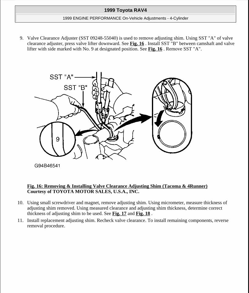
10. Valve Clearance Adjuster (SST 09248-55040) is used to remove adjusting shim. Using SST "A" of valve
Application (1) In. (mm)Intake .007-.011 (.19-.29)Exhaust .011-.015 (.29-.38)(1) Adjust valve clearance with engine cold.
1999 Toyota RAV4
1999 ENGINE PERFORMANCE On-Vehicle Adjustments - 4-Cylinder
Microsoft
Sunday, November 22, 2009 10:25:31 AM Page 2 © 2005 Mitchell Repair Information Company, LLC.

clearance adjuster, press valve lifter downward. See Fig. 2 . Install SST "B" between camshaft and valve lifter with side marked with No. 9 at designated position. See Fig. 2 . Remove SST "A".
Fig. 2: Removing & Installing Valve Clearance Adjusting Shim (Camry, Camry Solara, Celica & RAV4) Courtesy of TOYOTA MOTOR SALES, U.S.A., INC.
11. Using small screwdriver and magnet, remove adjusting shim. Using micrometer, measure thickness of adjusting shim removed. Using measured clearance and adjusting shim thickness, determine correct thickness of adjusting shim to be used. See Fig. 5 and Fig. 6 . Install replacement adjusting shim. Recheck valve clearance.
12. Before installing valve cover and gasket, apply sealant at specified areas on cylinder head. See Fig. 3 . Install gasket and valve cover.
13. Install grommets in original location with marking on grommet aligned in designated area. See Fig. 4 . Install and tighten valve cover nuts to specification. See TORQUE SPECIFICATIONS . To install remaining components, reverse removal procedure.
1999 Toyota RAV4
1999 ENGINE PERFORMANCE On-Vehicle Adjustments - 4-Cylinder
Microsoft
Sunday, November 22, 2009 10:25:31 AM Page 3 © 2005 Mitchell Repair Information Company, LLC.

Fig. 3: Locating Valve Cover Sealant Application Areas (Camry, Camry Solara, Celica & RAV4) Courtesy of TOYOTA MOTOR SALES, U.S.A., INC.
1999 Toyota RAV4
1999 ENGINE PERFORMANCE On-Vehicle Adjustments - 4-Cylinder
Microsoft
Sunday, November 22, 2009 10:25:31 AM Page 4 © 2005 Mitchell Repair Information Company, LLC.

Fig. 4: Aligning Typical Grommets On Valve Cover (Camry, Camry Solara, Celica & RAV4) Courtesy of TOYOTA MOTOR SALES, U.S.A., INC.
1999 Toyota RAV4
1999 ENGINE PERFORMANCE On-Vehicle Adjustments - 4-Cylinder
Microsoft
Sunday, November 22, 2009 10:25:31 AM Page 5 © 2005 Mitchell Repair Information Company, LLC.

1999 Toyota RAV4
1999 ENGINE PERFORMANCE On-Vehicle Adjustments - 4-Cylinder
Microsoft
Sunday, November 22, 2009 10:25:31 AM Page 6 © 2005 Mitchell Repair Information Company, LLC.

Fig. 5: Intake Valve Adjusting Shim Selection Chart (Camry, Camry Solara, Celica & RAV4)Courtesy of TOYOTA MOTOR SALES, U.S.A., INC.
1999 Toyota RAV4
1999 ENGINE PERFORMANCE On-Vehicle Adjustments - 4-Cylinder
Microsoft
Sunday, November 22, 2009 10:25:31 AM Page 7 © 2005 Mitchell Repair Information Company, LLC.

1999 Toyota RAV4
1999 ENGINE PERFORMANCE On-Vehicle Adjustments - 4-Cylinder
Microsoft
Sunday, November 22, 2009 10:25:31 AM Page 8 © 2005 Mitchell Repair Information Company, LLC.

Fig. 6: Exhaust Valve Adjusting Shim Selection Chart (Camry, Camry Solara, Celica & RAV4)Courtesy of TOYOTA MOTOR SALES, U.S.A., INC.
Corolla
1. Disconnect spark plug wires from spark plugs and valve cover. Disconnect necessary hoses and engine wiring cover for removal of valve cover.
2. Remove valve cover bolts/nuts, seal washers, cable bracket, valve cover and gasket. Rotate crankshaft clockwise (viewed from timing chain end of engine) until crankshaft pulley timing mark (groove) aligns with "0" mark on timing chain cover and cylinder No. 1 is at TDC on compression stroke. Cylinder No. 1 is front cylinder at timing chain end of engine.
3. Ensure reference marks on camshaft sprockets are aligned and positioned in a straight line at top surface on timing chain cover. See Fig. 7 . If reference marks are not as specified, rotate crankshaft clockwise one full revolution (360 degrees) and realign crankshaft pulley timing mark (groove) with "0" mark on timing chain cover and then recheck reference mark alignment.
Fig. 7: Checking Reference Mark Alignment (Corolla) Courtesy of TOYOTA MOTOR SALES, U.S.A., INC.
1999 Toyota RAV4
1999 ENGINE PERFORMANCE On-Vehicle Adjustments - 4-Cylinder
Microsoft
Sunday, November 22, 2009 10:25:31 AM Page 9 © 2005 Mitchell Repair Information Company, LLC.

4. With cylinder No. 1 at TDC on compression stroke, use feeler gauge to check valve clearance between valve lifter and camshaft on specified valves. Perform STEP 1. See Fig. 8 . Record valve clearance.
5. To check remaining valves, rotate crankshaft clockwise one full revolution (360 degrees) and realign crankshaft pulley timing mark (groove) with "0" mark on timing chain cover. Using feeler gauge, measure valve clearance on specified valves. Perform STEP 2. See Fig. 8 . Record valve clearance.
Fig. 8: Identifying Cylinder Numbers & Checking Valve Clearance (Corolla) Courtesy of TOYOTA MOTOR SALES, U.S.A., INC.
6. Ensure valve clearance is within specification. See VALVE CLEARANCE SPECIFICATIONS (COROLLA) table.
VALVE CLEARANCE SPECIFICATIONS (COROLLA)
1999 Toyota RAV4
1999 ENGINE PERFORMANCE On-Vehicle Adjustments - 4-Cylinder
Microsoft
Sunday, November 22, 2009 10:25:31 AM Page 10 © 2005 Mitchell Repair Information Company, LLC.

7. If valve clearance requires adjustment, camshafts must be removed for access to valve lifters. Different thickness valve lifters are used. Manufacturer recommends placing reference mark on timing chain and camshaft sprockets, removing timing chain tensioner and then removing camshaft sprockets and camshafts for access to valve lifter while supporting timing chain. To remove camshafts, see appropriate article in ENGINES.
8. Remove valve lifter from cylinder head. Using micrometer, measure thickness of valve lifter. See Fig. 9 . Using measured clearance and valve lifter thickness, determine correct thickness of valve lifter to be used.See Fig. 12 and Fig. 13 . Install replacement valve lifter, camshafts and timing chain. Recheck valve clearance.
9. Before installing valve cover and gasket, apply sealant at specified areas on cylinder head. See Fig. 10 . Install gasket, valve cover, seal washers, bolts and nuts. Tighten valve cover bolts/nuts to specification in sequence. See Fig. 11 . See TORQUE SPECIFICATIONS . To install remaining components, reverse removal procedure.
Fig. 9: Measuring Valve Lifter Thickness (Corolla) Courtesy of TOYOTA MOTOR SALES, U.S.A., INC.
Application (1) In. (mm)Intake .006-.010 (.15-.25)Exhaust .010-.014 (.25-.35)(1) Adjust valve clearance with engine cold.
1999 Toyota RAV4
1999 ENGINE PERFORMANCE On-Vehicle Adjustments - 4-Cylinder
Microsoft
Sunday, November 22, 2009 10:25:31 AM Page 11 © 2005 Mitchell Repair Information Company, LLC.

Fig. 10: Locating Valve Cover Sealant Application Areas (Corolla) Courtesy of TOYOTA MOTOR SALES, U.S.A., INC.
1999 Toyota RAV4
1999 ENGINE PERFORMANCE On-Vehicle Adjustments - 4-Cylinder
Microsoft
Sunday, November 22, 2009 10:25:31 AM Page 12 © 2005 Mitchell Repair Information Company, LLC.

Fig. 11: Valve Cover Bolt/Nut Tightening Sequence (Corolla) Courtesy of TOYOTA MOTOR SALES, U.S.A., INC.
1999 Toyota RAV4
1999 ENGINE PERFORMANCE On-Vehicle Adjustments - 4-Cylinder
Microsoft
Sunday, November 22, 2009 10:25:31 AM Page 13 © 2005 Mitchell Repair Information Company, LLC.

Fig. 12: Intake Valve Lifter Selection Chart (Corolla) Courtesy of TOYOTA MOTOR SALES, U.S.A., INC.
1999 Toyota RAV4
1999 ENGINE PERFORMANCE On-Vehicle Adjustments - 4-Cylinder
Microsoft
Sunday, November 22, 2009 10:25:31 AM Page 14 © 2005 Mitchell Repair Information Company, LLC.

Fig. 13: Exhaust Valve Lifter Selection Chart (Corolla) Courtesy of TOYOTA MOTOR SALES, U.S.A., INC.
Tacoma & 4Runner
1. Remove air cleaner hose along with upper cap on air cleaner and mass airflow meter. Remove intake air connector for access to valve cover. Intake air connector fits between air cleaner hose and throttle body.
2. Disconnect spark plug wires from spark plugs. Disconnect engine wiring, clamps and PCV hose for access to valve cover. Remove bolts, seal washers, valve cover and gasket.
3. Rotate crankshaft clockwise until crankshaft pulley timing mark (groove) aligns with "0" mark on timing chain cover and cylinder No. 1 is at TDC on compression stroke. Cylinder No. 1 is front cylinder at timing chain end of engine.
4. Ensure 1-dot and 2-dot timing marks on camshaft sprockets are aligned. See Fig. 14 . If timing marks are not aligned, rotate crankshaft clockwise one full revolution (360 degrees) and realign crankshaft pulley timing mark (groove) with "0" mark on timing chain cover.
1999 Toyota RAV4
1999 ENGINE PERFORMANCE On-Vehicle Adjustments - 4-Cylinder
Microsoft
Sunday, November 22, 2009 10:25:31 AM Page 15 © 2005 Mitchell Repair Information Company, LLC.

Fig. 14: Aligning Camshaft Sprocket Timing Marks (Tacoma & 4Runner) Courtesy of TOYOTA MOTOR SALES, U.S.A., INC.
5. With cylinder No. 1 at TDC on compression stroke, use feeler gauge to measure valve clearance between valve lifter and camshaft on specified valves. Perform STEP 1. See Fig. 15 . Record valve clearance.
6. To check remaining valves, rotate crankshaft clockwise one full revolution (360 degrees) and realign crankshaft pulley timing mark (groove) with "0" mark on timing chain cover. Using feeler gauge, measure valve clearance on specified valves. Perform STEP 2. See Fig. 15 . Record valve clearance.
1999 Toyota RAV4
1999 ENGINE PERFORMANCE On-Vehicle Adjustments - 4-Cylinder
Microsoft
Sunday, November 22, 2009 10:25:31 AM Page 16 © 2005 Mitchell Repair Information Company, LLC.

Fig. 15: Identifying Cylinder Numbers & Checking Valve Clearance (Tacoma & 4Runner) Courtesy of TOYOTA MOTOR SALES, U.S.A., INC.
7. Ensure valve clearance is within specification. See VALVE CLEARANCE SPECIFICATIONS (TACOMA & 4RUNNER) table.
VALVE CLEARANCE SPECIFICATIONS (TACOMA & 4RUNNER)
8. If valve clearance requires adjustment, rotate crankshaft so camshaft lobe on valve to be adjusted is facingupward, away from valve lifter. Rotate valve lifter so notch on valve lifter is toward spark plug.
Application (1) In. (mm)Intake .006-.010 (.15-.25)Exhaust .010-.014 (.25-.35)(1) Adjust valve clearance with engine cold.
1999 Toyota RAV4
1999 ENGINE PERFORMANCE On-Vehicle Adjustments - 4-Cylinder
Microsoft
Sunday, November 22, 2009 10:25:31 AM Page 17 © 2005 Mitchell Repair Information Company, LLC.
9. Valve Clearance Adjuster (SST 09248-55040) is used to remove adjusting shim. Using SST "A" of valve clearance adjuster, press valve lifter downward. See Fig. 16 . Install SST "B" between camshaft and valve lifter with side marked with No. 9 at designated position. See Fig. 16 . Remove SST "A".
Fig. 16: Removing & Installing Valve Clearance Adjusting Shim (Tacoma & 4Runner) Courtesy of TOYOTA MOTOR SALES, U.S.A., INC.
10. Using small screwdriver and magnet, remove adjusting shim. Using micrometer, measure thickness of adjusting shim removed. Using measured clearance and adjusting shim thickness, determine correct thickness of adjusting shim to be used. See Fig. 17 and Fig. 18 .
11. Install replacement adjusting shim. Recheck valve clearance. To install remaining components, reverse removal procedure.
1999 Toyota RAV4
1999 ENGINE PERFORMANCE On-Vehicle Adjustments - 4-Cylinder
Microsoft
Sunday, November 22, 2009 10:25:31 AM Page 18 © 2005 Mitchell Repair Information Company, LLC.

Fig. 17: Intake Valve Adjusting Shim Selection Chart (Tacoma & 4Runner) Courtesy of TOYOTA MOTOR SALES, U.S.A., INC.
1999 Toyota RAV4
1999 ENGINE PERFORMANCE On-Vehicle Adjustments - 4-Cylinder
Microsoft
Sunday, November 22, 2009 10:25:31 AM Page 19 © 2005 Mitchell Repair Information Company, LLC.

Fig. 18: Exhaust Valve Adjusting Shim Selection Chart (Tacoma & 4Runner) Courtesy of TOYOTA MOTOR SALES, U.S.A., INC.
IGNITION TIMING
4-CYLINDER IGNITION TIMING
Camry, Camry Solara & Celica
1. Start engine and warm engine to normal operating temperature. Shut engine off. Connect timing light to spark plug wire on cylinder No. 1. Cylinder No. 1 is front cylinder at timing belt end of engine.
2. Remove cover and connect scan tool to data link connector No. 3. See Fig. 19 -Fig. 21 . Scan tool is used to read engine RPM.
3. Install Jumper Wire (SST 09843-18020) between terminals TE1 and E1 on data link connector No. 1. See Fig. 26 -Fig. 28 . See DATA LINK CONNECTOR NO. 1 LOCATIONS table.
DATA LINK CONNECTOR NO. 1 LOCATIONS Application LocationCamry & Camry Solara Passenger's Side Of Engine Compartment, Near
Strut Tower
1999 Toyota RAV4
1999 ENGINE PERFORMANCE On-Vehicle Adjustments - 4-Cylinder
Microsoft
Sunday, November 22, 2009 10:25:31 AM Page 20 © 2005 Mitchell Repair Information Company, LLC.

4. Apply parking brake. Place transaxle in Neutral. Start engine and maintain engine at 1000-1300 RPM for 5 seconds and then ensure engine returns to idle.
5. Timing marks are located on timing belt cover, near crankshaft pulley. Ensure base timing is within specification at idle with transaxle in Neutral, and with A/C and all accessories off. See IGNITION TIMING SPECIFICATIONS table.
6. Remove jumper wire from data link connector No. 1. Ensure ECM controlled timing is within specification. See IGNITION TIMING SPECIFICATIONS table. Shut engine off. Remove timing light and scan tool.
Corolla
1. Start engine and warm engine to normal operating temperature. Shut engine off. Connect timing light to spark plug wire on cylinder No. 1. Cylinder No. 1 is front cylinder at timing chain end of engine.
2. Connect scan tool to data link connector No. 3. See Fig. 22 . Scan tool is used to read engine RPM.
3. Install Jumper Wire (SST 09843-18020) between terminals TE1 and E1 on data link connector No. 1. See Fig. 29 . Data link connector No. 1 is located at driver's side of engine compartment, near strut tower.
4. Apply parking brake. Place transaxle in Neutral. Start engine and maintain engine at 1000-1300 RPM for 5 seconds and then ensure engine returns to idle.
5. Timing marks are located on timing chain cover, near crankshaft pulley. Ensure base timing is within specification at idle with transaxle in Neutral, and with A/C and all accessories off. See IGNITION TIMING SPECIFICATIONS table.
6. Remove jumper wire from data link connector No. 1. Ensure ECM controlled timing is within specification. See IGNITION TIMING SPECIFICATIONS table. Shut engine off. Remove timing light and scan tool.
RAV4
1. Start engine and warm engine to normal operating temperature. Shut engine off. Connect timing light to spark plug wire on cylinder No. 1. Cylinder No. 1 is front cylinder at timing belt end of engine.
2. Remove cover from instrument panel and connect scan tool to data link connector No. 3. See Fig. 23 . Scan tool is used to read engine RPM.
3. Install Jumper Wire (SST 09843-18020) between terminals TE1 and E1 on data link connector No. 1. See Fig. 30 . Data link connector No. 1 is located on timing belt end of engine, above generator.
4. Apply parking brake. Place transaxle in Neutral. Start engine and allow engine to idle.
5. Timing marks are located on timing belt cover, near crankshaft pulley. Ensure base timing is within specification at idle with transaxle in Neutral, and with A/C and all accessories off. See IGNITION TIMING SPECIFICATIONS table.
6. Remove jumper wire from data link connector No. 1. Ensure ECM controlled timing is within specification. See IGNITION TIMING SPECIFICATIONS table. Shut engine off. Remove timing light and scan tool.
Celica Driver's Side Rear Corner Of Engine Compartment, Near Brake Booster
1999 Toyota RAV4
1999 ENGINE PERFORMANCE On-Vehicle Adjustments - 4-Cylinder
Microsoft
Sunday, November 22, 2009 10:25:31 AM Page 21 © 2005 Mitchell Repair Information Company, LLC.

Tacoma & 4Runner
1. Start engine and warm engine to normal operating temperature. Shut engine off. Connect timing light to spark plug wire on cylinder No. 1. Cylinder No. 1 is front cylinder at timing chain end of engine.
2. Connect scan tool to data link connector No. 3. See Fig. 24 and Fig. 25 . Scan tool is used to read engine RPM.
3. Install Jumper Wire (SST 09843-18020) between terminals TE1 and E1 on data link connector No. 1. See Fig. 31 . Data link connector No. 1 is located on end of intake manifold at front of engine.
4. Apply parking brake. Place transmission in Neutral. Start engine. Maintain engine at 1000 RPM for 5 seconds and then ensure engine returns to idle.
5. Timing marks are located on timing chain cover, near crankshaft pulley. Ensure base timing is within specification at idle with transmission in Neutral, and with A/C and all accessories off. See IGNITION TIMING SPECIFICATIONS table.
6. Remove jumper wire from data link connector No. 1. Ensure ECM controlled timing is within specification. See IGNITION TIMING SPECIFICATIONS table. Shut engine off. Remove timing light and scan tool.
IGNITION TIMING SPECIFICATIONS (Degrees BTDC @ Idle) (1)
Application (2) Base Timing (3) ECM Controlled TimingCamry, Camry Solara & Celica 8-12 0-10Corolla 8-12 6-15RAV4 8-12 0-10Tacoma & 4Runner 3-7 4-17(1) Check with engine at normal operating temperature, transmission/transaxle in Neutral, parking brake
applied, and A/C and all accessories off.(2) With Jumper Wire (SST 09843-18020) installed between terminals TE1 and E1 on data link
connector No. 1.(3) With jumper wire removed from data link connector No. 1.
1999 Toyota RAV4
1999 ENGINE PERFORMANCE On-Vehicle Adjustments - 4-Cylinder
Microsoft
Sunday, November 22, 2009 10:25:31 AM Page 22 © 2005 Mitchell Repair Information Company, LLC.

Fig. 19: Connecting Scan Tool (Camry) Courtesy of TOYOTA MOTOR SALES, U.S.A., INC.
1999 Toyota RAV4
1999 ENGINE PERFORMANCE On-Vehicle Adjustments - 4-Cylinder
Microsoft
Sunday, November 22, 2009 10:25:31 AM Page 23 © 2005 Mitchell Repair Information Company, LLC.

Fig. 20: Connecting Scan Tool (Camry Solara) Courtesy of TOYOTA MOTOR SALES, U.S.A., INC.
1999 Toyota RAV4
1999 ENGINE PERFORMANCE On-Vehicle Adjustments - 4-Cylinder
Microsoft
Sunday, November 22, 2009 10:25:31 AM Page 24 © 2005 Mitchell Repair Information Company, LLC.

Fig. 21: Connecting Scan Tool (Celica) Courtesy of TOYOTA MOTOR SALES, U.S.A., INC.
1999 Toyota RAV4
1999 ENGINE PERFORMANCE On-Vehicle Adjustments - 4-Cylinder
Microsoft
Sunday, November 22, 2009 10:25:31 AM Page 25 © 2005 Mitchell Repair Information Company, LLC.

Fig. 22: Connecting Scan Tool (Corolla) Courtesy of TOYOTA MOTOR SALES, U.S.A., INC.
1999 Toyota RAV4
1999 ENGINE PERFORMANCE On-Vehicle Adjustments - 4-Cylinder
Microsoft
Sunday, November 22, 2009 10:25:31 AM Page 26 © 2005 Mitchell Repair Information Company, LLC.

Fig. 23: Connecting Scan Tool (RAV4) Courtesy of TOYOTA MOTOR SALES, U.S.A., INC.
1999 Toyota RAV4
1999 ENGINE PERFORMANCE On-Vehicle Adjustments - 4-Cylinder
Microsoft
Sunday, November 22, 2009 10:25:31 AM Page 27 © 2005 Mitchell Repair Information Company, LLC.

Fig. 24: Connecting Scan Tool (Tacoma) Courtesy of TOYOTA MOTOR SALES, U.S.A., INC.
1999 Toyota RAV4
1999 ENGINE PERFORMANCE On-Vehicle Adjustments - 4-Cylinder
Microsoft
Sunday, November 22, 2009 10:25:31 AM Page 28 © 2005 Mitchell Repair Information Company, LLC.

Fig. 25: Connecting Scan Tool (4Runner) Courtesy of TOYOTA MOTOR SALES, U.S.A., INC.
1999 Toyota RAV4
1999 ENGINE PERFORMANCE On-Vehicle Adjustments - 4-Cylinder
Microsoft
Sunday, November 22, 2009 10:25:31 AM Page 29 © 2005 Mitchell Repair Information Company, LLC.

Fig. 26: Installing Jumper Wire Between Data Link Connector No. 1 Terminals (Camry) Courtesy of TOYOTA MOTOR SALES, U.S.A., INC.
1999 Toyota RAV4
1999 ENGINE PERFORMANCE On-Vehicle Adjustments - 4-Cylinder
Microsoft
Sunday, November 22, 2009 10:25:31 AM Page 30 © 2005 Mitchell Repair Information Company, LLC.

Fig. 27: Installing Jumper Wire Between Data Link Connector No. 1 Terminals (Camry Solara) Courtesy of TOYOTA MOTOR SALES, U.S.A., INC.
1999 Toyota RAV4
1999 ENGINE PERFORMANCE On-Vehicle Adjustments - 4-Cylinder
Microsoft
Sunday, November 22, 2009 10:25:31 AM Page 31 © 2005 Mitchell Repair Information Company, LLC.

Fig. 28: Installing Jumper Wire Between Data Link Connector No. 1 Terminals (Celica) Courtesy of TOYOTA MOTOR SALES, U.S.A., INC.
1999 Toyota RAV4
1999 ENGINE PERFORMANCE On-Vehicle Adjustments - 4-Cylinder
Microsoft
Sunday, November 22, 2009 10:25:31 AM Page 32 © 2005 Mitchell Repair Information Company, LLC.

Fig. 29: Installing Jumper Wire Between Data Link Connector No. 1 Terminals (Corolla) Courtesy of TOYOTA MOTOR SALES, U.S.A., INC.
1999 Toyota RAV4
1999 ENGINE PERFORMANCE On-Vehicle Adjustments - 4-Cylinder
Microsoft
Sunday, November 22, 2009 10:25:31 AM Page 33 © 2005 Mitchell Repair Information Company, LLC.

Fig. 30: Installing Jumper Wire Between Data Link Connector No. 1 Terminals (RAV4) Courtesy of TOYOTA MOTOR SALES, U.S.A., INC.
1999 Toyota RAV4
1999 ENGINE PERFORMANCE On-Vehicle Adjustments - 4-Cylinder
Microsoft
Sunday, November 22, 2009 10:25:31 AM Page 34 © 2005 Mitchell Repair Information Company, LLC.

Fig. 31: Installing Jumper Wire Between Data Link Connector No. 1 Terminals (Tacoma & 4Runner) Courtesy of TOYOTA MOTOR SALES, U.S.A., INC.
IDLE SPEED & MIXTURE
4-CYLINDER IDLE SPEED & MIXTURE
Camry, Camry Solara, Celica, Corolla, RAV4, Tacoma & 4Runner
NOTE: Mixture adjustment is not possible on any model.
NOTE: Idle speed is controlled by Engine Control Module (ECM) and is not adjustable. Check idle speed with engine at normal operating temperature, transmission/transaxle in Neutral, parking brake applied, air cleaner and all vacuum hoses installed, electronic fuel injection system wiring connectors properly installed, ignition timing properly set, electric cooling fan off (if equipped), and A/C and all accessories off.
1999 Toyota RAV4
1999 ENGINE PERFORMANCE On-Vehicle Adjustments - 4-Cylinder
Microsoft
Sunday, November 22, 2009 10:25:31 AM Page 35 © 2005 Mitchell Repair Information Company, LLC.

1. Start engine and warm engine to normal operating temperature. Shut engine off. Remove cover (if equipped) and connect scan tool to data link connector No. 3. See Fig. 19 -Fig. 25 . Scan tool is used to read engine RPM.
2. Apply parking brake. Place transmission/transaxle in Neutral. Start engine and maintain engine at 2500 RPM for 90 seconds and then allow engine to idle. Ensure idle speed is within specification. See IDLE SPEED SPECIFICATIONS table.
3. If idle speed is not within specification, check air intake system, Idle Air Control (IAC) valve, wiring and Engine Control Module (ECM). See IDLE CONTROL SYSTEM in SYSTEM & COMPONENT TESTING - 4-CYLINDER article. Shut engine off. Remove scan tool.
IDLE SPEED SPECIFICATIONS (1)
THROTTLE POSITION SENSOR
4-CYLINDER THROTTLE POSITION SENSOR
Camry & Camry Solara
1. Manufacturer does not list procedure for Throttle Position (TP) sensor adjustment. Only information available is for checking resistance of TP sensor.
2. Disconnect electrical connector from TP sensor. Note electrical terminals on TP sensor. See Fig. 32 . Apply vacuum to throttle opener.
3. Using ohmmeter, check resistance between specified terminals in relation to throttle position. See THROTTLE POSITION SENSOR RESISTANCE table. Replace components as necessary if resistance is not within specification.
Celica
1. Disconnect electrical connector from Throttle Position (TP) sensor. Loosen TP sensor mounting screws. Connect ohmmeter between terminals IDL and E2. See Fig. 33 .
2. Apply vacuum to throttle opener. To set initial clearance, insert .024" (.60 mm) feeler gauge between throttle stop screw and throttle lever.
3. Gradually rotate TP sensor clockwise until ohmmeter deflects. Tighten TP sensor mounting screws. Remove feeler gauge. Reinsert a .020" (.50 mm) feeler gauge. Continuity should exist between terminals
Application RPMCamry, Camry Solara, Celica & Corolla
650-750
RAV4 700-800Tacoma & 4Runner 650-750(1) Check with engine at normal operating temperature, transmission/transaxle
in Neutral, parking brake applied, air cleaner and all vacuum hoses installed, electronic fuel injection system wiring connectors properly installed, ignition timing properly set, electric cooling fan off (if equipped), and A/C and all accessories off.
1999 Toyota RAV4
1999 ENGINE PERFORMANCE On-Vehicle Adjustments - 4-Cylinder
Microsoft
Sunday, November 22, 2009 10:25:31 AM Page 36 © 2005 Mitchell Repair Information Company, LLC.

IDL and E2. Remove feeler gauge.
4. Reinsert a .028" (.70 mm) feeler gauge. No continuity should exist between terminals IDL and E2. Remove feeler gauge and ohmmeter. Install electrical connector on TP sensor.
Corolla
1. Manufacturer does not list procedure for Throttle Position (TP) sensor adjustment. Only information available is for checking resistance of TP sensor.
2. Disconnect electrical connector from TP sensor. Note electrical terminals on TP sensor. See Fig. 34 .
3. Using ohmmeter, check resistance between specified terminals in relation to throttle position. See THROTTLE POSITION SENSOR RESISTANCE table. Replace components as necessary if resistance is not within specification.
RAV4
1. Manufacturer does not list procedure for Throttle Position (TP) sensor adjustment. Only information available is for checking resistance of TP sensor.
2. Note location of E2 terminal (Brown wire), VC terminal (Yellow wire) and VTA terminal (Blue/Red wire) on TP sensor. Disconnect electrical connector from TP sensor. Apply vacuum to throttle opener.
3. Using ohmmeter, check resistance between specified terminals in relation to throttle position. See THROTTLE POSITION SENSOR RESISTANCE table. Replace components as necessary if resistance is not within specification.
Tacoma & 4Runner
1. Manufacturer does not list procedure for Throttle Position (TP) sensor adjustment. Only information available is for checking resistance of TP sensor.
2. Disconnect electrical connector from TP sensor. Note electrical terminals on TP sensor. See Fig. 35 . Apply vacuum to throttle opener.
3. Using ohmmeter, check resistance between specified terminals in relation to throttle position. See THROTTLE POSITION SENSOR RESISTANCE table. Replace components as necessary if resistance is not within specification.
THROTTLE POSITION SENSOR RESISTANCE Application Throttle Position Terminals OhmsCamry & Camry Solara (1)
Fully Closed VTA & E2 200-5700
Fully Open VTA & E2 2000-10,200VC & E2 2500-5900
Corolla Fully Closed VTA & E2 200-5700Fully Open VTA & E2 2000-10,200
VC & E2 2500-5900RAV4, Tacoma & 4Runner (1)
Fully Closed VTA & E2 200-5700
1999 Toyota RAV4
1999 ENGINE PERFORMANCE On-Vehicle Adjustments - 4-Cylinder
Microsoft
Sunday, November 22, 2009 10:25:31 AM Page 37 © 2005 Mitchell Repair Information Company, LLC.

Fig. 32: Identifying TP Sensor Terminals (Camry & Camry Solara) Courtesy of TOYOTA MOTOR SALES, U.S.A., INC.
Fully Open VTA & E2 2000-10,200VC & E2 2500-5900
(1) Apply vacuum to throttle opener before checking TP sensor.
1999 Toyota RAV4
1999 ENGINE PERFORMANCE On-Vehicle Adjustments - 4-Cylinder
Microsoft
Sunday, November 22, 2009 10:25:31 AM Page 38 © 2005 Mitchell Repair Information Company, LLC.

Fig. 33: Identifying TP Sensor Terminals (Celica) Courtesy of TOYOTA MOTOR SALES, U.S.A., INC.
1999 Toyota RAV4
1999 ENGINE PERFORMANCE On-Vehicle Adjustments - 4-Cylinder
Microsoft
Sunday, November 22, 2009 10:25:31 AM Page 39 © 2005 Mitchell Repair Information Company, LLC.

Fig. 34: Identifying TP Sensor Terminals (Corolla) Courtesy of TOYOTA MOTOR SALES, U.S.A., INC.
1999 Toyota RAV4
1999 ENGINE PERFORMANCE On-Vehicle Adjustments - 4-Cylinder
Microsoft
Sunday, November 22, 2009 10:25:31 AM Page 40 © 2005 Mitchell Repair Information Company, LLC.

Fig. 35: Identifying TP Sensor Terminals (Tacoma & 4Runner) Courtesy of TOYOTA MOTOR SALES, U.S.A., INC.
THROTTLE OPENER
THROTTLE OPENER
Camry, Camry Solara, Celica, RAV4, Tacoma & 4Runner
For testing and adjustment procedures, see THROTTLE CONTROLS in SYSTEM & COMPONENT TESTING - 4-CYLINDER article.
MISCELLANEOUS CONTROLS
PARK/NEUTRAL POSITION (PNP) SWITCH
For adjustment of PNP switch, see PARK/NEUTRAL POSITION (PNP) SWITCH under ENGINE SENSORS & SWITCHES in REMOVAL, OVERHAUL & INSTALLATION - 4-CYLINDER article.
TORQUE SPECIFICATIONS
TORQUE SPECIFICATIONS Application Ft. Lbs. (N.m)
1999 Toyota RAV4
1999 ENGINE PERFORMANCE On-Vehicle Adjustments - 4-Cylinder
Microsoft
Sunday, November 22, 2009 10:25:31 AM Page 41 © 2005 Mitchell Repair Information Company, LLC.

Valve Cover Bolt Or NutCamry, Camry Solara & Celica 33 (45)Corolla (1)
RAV4 33 (45)Tacoma & 4Runner (2)
(1) Tighten bolts/nuts with washer to 80 INCH lbs. (9.0 N.m). Tighten bolts/nuts without washer to 97 INCH lbs. (11.0 N.m). Tighten bolts/nuts to specification in sequence. See Fig. 11 .
(2) Information is not available from manufacturer.
1999 Toyota RAV4
1999 ENGINE PERFORMANCE On-Vehicle Adjustments - 4-Cylinder
Microsoft
Sunday, November 22, 2009 10:25:31 AM Page 42 © 2005 Mitchell Repair Information Company, LLC.