prisma ii bdr 2:1 dual receive processor installation and … · 1-2 introduction 78-748704-01 rev...
TRANSCRIPT

Prisma II bdr 2:1 Dual Receive Processor Installation and Operation Guide

For Your Safety
Explanation of Warning and Caution Icons
Avoid personal injury and product damage! Do not proceed beyond any symbol until you fully understand the indicated conditions.
The following warning and caution icons alert you to important information about the safe operation of this product:
You may find this symbol in the document that accompanies this product. This symbol indicates important operating or maintenance instructions.
You may find this symbol affixed to the product. This symbol indicates a live terminal where a dangerous voltage may be present; the tip of the flash points to the terminal device.
You may find this symbol affixed to the product. This symbol indicates a protective ground terminal.
You may find this symbol affixed to the product. This symbol indicates a chassis terminal (normally used for equipotential bonding).
You may find this symbol affixed to the product. This symbol warns of a potentially hot surface.
You may find this symbol affixed to the product and in this document. This symbol indicates an infrared laser that transmits intensity-modulated light and emits invisible laser radiation or an LED that transmits intensity-modulated light.
Important Please read this entire guide. If this guide provides installation or operation instructions, give particular attention to all safety statements included in this guide.

Notices
Trademark Acknowledgments Cisco and the Cisco logo are trademarks or registered trademarks of Cisco and/or its affiliates in the U.S. and other countries. To view a list of cisco trademarks, go to this URL: www.cisco.com/go/trademarks. Third party trademarks mentioned are the property of their respective owners. The use of the word partner does not imply a partnership relationship between Cisco and any other company. (1110R)
Publication Disclaimer Cisco Systems, Inc. assumes no responsibility for errors or omissions that may appear in this publication. We reserve the right to change this publication at any time without notice. This document is not to be construed as conferring by implication, estoppel, or otherwise any license or right under any copyright or patent, whether or not the use of any information in this document employs an invention claimed in any existing or later issued patent.
Copyright © 2008, 2012 Cisco and/or its affiliates. All rights reserved. Printed in the United States of America. Information in this publication is subject to change without notice. No part of this publication may be reproduced or transmitted in any form, by photocopy, microfilm, xerography, or any other means, or incorporated into any information retrieval system, electronic or mechanical, for any purpose, without the express permission of Cisco Systems, Inc.

Contents
78-748704-01 Rev C iii
Safety Precautions ..................................................................................................................................... vi
Compliance .............................................................................................................................................. viii
Laser Safety ................................................................................................................................................ ix
Chapter 1 Introduction Overview ........................................................................................................................ 1-1 Prisma II bdr 2:1 Dual Receive Processor Overview ............................................... 1-2 Processor Front Panel ................................................................................................... 1-5 Processor Back Panel .................................................................................................... 1-7 Optical Receiver Front Panel ....................................................................................... 1-8 Processor Configuration Summary ............................................................................ 1-9 Processor Configuration Options ............................................................................. 1-10 Processor Configuration Examples .......................................................................... 1-14
Chapter 2 Installation Overview ........................................................................................................................ 2-1 Prepare for Installation ................................................................................................. 2-2 Site Requirements ......................................................................................................... 2-3 Connect RF Cables to the Chassis ............................................................................... 2-6 Install the Processor in the Chassis ............................................................................. 2-8 Connect Optical Cables .............................................................................................. 2-10 Install Optical Receivers in the Processor ................................................................ 2-13 Connect Multiple Chassis .......................................................................................... 2-15 Alarm I/O Connections ............................................................................................. 2-16 Prisma II Redundancy Interface Panel Overview .................................................. 2-21 Interface Panel Features ............................................................................................. 2-22 Interface Panel Installation and Connections ......................................................... 2-23 Master/Slave Connections Overview ...................................................................... 2-26
Contents, Continued
iv 78-748704-01 Rev C
Chapter 3 Operation Using the ICIM Overview ........................................................................................................................ 3-1 ICIM Introduction ......................................................................................................... 3-2 ICIM Front Panel ........................................................................................................... 3-3 ICIM Password .............................................................................................................. 3-6 ICIM Operation ........................................................................................................... 3-14 Monitor Processor Status Using the ICIM ............................................................... 3-18 Configure the Processor Using the ICIM ................................................................. 3-22 Check Processor Alarms Using the ICIM ................................................................ 3-26 Check Manufacturing Data Using the ICIM ........................................................... 3-30 Save the Configuration Using the ICIM .................................................................. 3-33
Chapter 4 Operation Using LCI Overview ........................................................................................................................ 4-1 LCI Introduction ........................................................................................................... 4-2 System Requirements ................................................................................................... 4-3 Install LCI ....................................................................................................................... 4-4 Obtain and Install the Prisma II Driver Upgrade ..................................................... 4-7 Connect the Computer to the Chassis ........................................................................ 4-8 Start LCI ......................................................................................................................... 4-9 LCI Device Tree Overview ........................................................................................ 4-11 Access the Device Details Window .......................................................................... 4-12 Check the Operating Status ....................................................................................... 4-15 Configure the Processor ............................................................................................. 4-17 Check Processor Alarms ............................................................................................ 4-20 Check Device Properties ............................................................................................ 4-22
Contents, Continued
78-748704-01 Rev C v
Chapter 5 Maintenance and Troubleshooting Overview ........................................................................................................................ 5-1 Module Maintenance .................................................................................................... 5-2 General Troubleshooting Information ....................................................................... 5-3 Troubleshoot Alarm Conditions ................................................................................. 5-4 Troubleshoot LCI .......................................................................................................... 5-5 Clean Fiber-Optic Connectors ................................................................................... 5-12
Chapter 6 Customer Information .................................................................................................... 6-1
Glossary ...................................................................................................................................... Glossary-1
Index .................................................................................................................................................. Index-1

vi 78-748704-01 Rev C
Safety Precautions
Protect Yourself From Electric Shock and Your System From Damage! • This product complies with international safety and design standards. Observe all
safety procedures that appear throughout this guide, and the safety symbols that are affixed to this product.
• If circumstances impair the safe operation of this product, stop operation and secure this product against further operation.
Avoid personal injury and product damage! Do not proceed beyond any symbol until you fully understand the indicated conditions!
You will find this symbol in the literature that accompanies this product. This symbol indicates important operating or maintenance instructions.
You may find this symbol affixed to this product. This symbol indicates a live terminal; the flash points to the terminal device.
You may find this symbol affixed to this product. This symbol indicates a protective earth terminal.
You may find this symbol affixed to this product. This symbol indicates excessive or dangerous heat.

78-748704-01 Rev C vii
Safety Precautions, Continued
Enclosure • Do not allow moisture to enter this product. • Do not open the enclosure of this product unless otherwise specified. • Do not push objects through openings in the enclosure of this product.
Cables • Always pull on the plug or the connector to disconnect a cable. Never pull on the
cable itself. • Do not walk on or place stress on cables or plugs.
Factory Service
Refer service only to service personnel who are authorized by the factory.

viii 78-748704-01 Rev C
Compliance
Laser and Electrical Safety
UL 1419:1997: A sample of this equipment has been tested and found to meet the requirements of UL 1419:1997.
CSA C22.2 No. 1:1998: A sample of this equipment has been tested and found to meet the requirements of CSA C22.2 No. 1:1998.
Electromagnetic Compatibility
FCC Part 15 Subpart B: This equipment has been tested and found to comply with the limits for a Class A digital device according to Part 15 of FCC Rules. These limits are designed to provide reasonable protection against harmful interference when the equipment is operated in a commercial environment.
This equipment generates, uses, and can radiate radio frequency energy and, if not installed and used in accordance with the instruction manual, may cause harmful interference to radio communications. Operation of this equipment in a residential area is likely to cause harmful interference in which case the user will be required to correct the interference at his own expense. Industry Canada ICES-003: This Class A digital apparatus meets all the requirements of the Canadian Interference-Causing Equipment Regulations.
Industrie Canadienne ICES-003: Cet appareil numèrique de la class A respecte toutes les exigences du Règlement sur le matèriel brouilleur du Canada.

78-748704-01 Rev C ix
Laser Safety
Introduction
This product contains an infrared laser that transmits intensity-modulated light and emits invisible radiation.
Warning: Radiation
WARNING:
• Avoid personal injury! Use of controls, adjustments, or procedures other than those specified herein may result in hazardous radiation exposure.
• Avoid personal injury! The laser light source on this product emits invisible laser radiation. Avoid direct exposure to the laser light source.
• Do not apply power to this product if the fiber is unmated or unterminated. • Do not stare into an unmated fiber or at any mirror-like surface that could reflect
light that is emitted from an unterminated fiber. • Do not view an activated fiber with optical instruments.
Warning: Fiber Chips
WARNING: Avoid personal injury! Wear safety glasses and use extreme caution when you handle the glass chips that are inside the cladding of the optical fiber. X-ray cannot detect these glass chips if they become embedded in the skin. Place the chips immediately in a small waste container and discard.
Modifications
Do not make modifications to this product without the approval of Cisco.
Whenever modifications that may affect hazard levels are made to the optical fiber communication system, the person or organization that performs such modification must reassess hazard levels. They must do this by conducting tests and measurements wherever appropriate for the ensurance of compliance. If there is a change in the hazard level, they must re-label this product.

x 78-748704-01 Rev C
Laser Safety, Continued
Laser Warning Labels
The receiver bears the following labels.

78-748704-01 Rev C Introduction 1-1
Chapter 1 Introduction
Overview
Introduction This chapter introduces the front and back panels of the Prisma IITM bdrTM 2:1 Dual Receive Processor, the Prisma II bdr Optical Receiver and presents a configuration overview.
Qualified Personnel Only appropriately qualified and trained personnel should attempt to install this product.
WARNING:
Allow only qualified personnel to install, operate, maintain, and service this product. Otherwise, personal injury or equipment damage may occur.
In This Chapter This chapter contains the following topics.
Topic See Page
Prisma II bdr 2:1 Dual Receive Processor Overview 1-2
Processor Front Panel 1-5
Processor Back Panel 1-7
Optical Receiver Front Panel 1-8
Processor Configuration Summary 1-9
Processor Configuration Options 1-10
Processor Configuration Examples 1-14

1-2 Introduction 78-748704-01 Rev C
Prisma II bdr 2:1 Dual Receive Processor Overview
Introduction The Prisma II optical network is an advanced transmission system designed to optimize network architectures and increase reliability, scalability, and cost effectiveness. The Prisma II bdr 2:1 Dual Receive Processor is designed to operate over a wide range of optical input powers and loss budgets. Microprocessor control allows ease of installation and flexibility of application. The Prisma II bdr Dual Receive Processor houses two independent optical receivers.
For the purpose of this guide, the Prisma II bdr 2:1 Dual Receive Processor is referred to as “the processor”. The Prisma II bdr Optical Receiver is referred to as “the optical receiver.”
Processor Features The processor has the following features. • Front panel green light emitting diode (LED) to indicate operating status • Front panel red LED to indicate alarm status • -20 dB input test point • Test point selector • Optical receiver insertion slots (two) • Plug-and-play capability • Compatibility with Local Craft Interface (LCI) software and Transmission
Network Control System (TNCS) software • Blind mate RF connections
78-748704-01 Rev C Introduction 1-3
Prisma II bdr 2:1 Dual Receive Processor Overview, Continued
Prisma II bdr Digital Reverse 2:1 Multiplexing System The Prisma II platform supports Cisco’s Baseband Digital Reverse technology. The Prisma II bdr Digital Reverse 2:1 Multiplexing System includes a unique approach for incorporating network redundancy.
On the transmit end of the system, typically in a hub or remote terminal, two 5 to 42 MHz analog reverse path signals are output of a transmit processor. The transmit processor converts each signal to a baseband digital data stream and time division multiplexes the two streams into a single data stream.
On the receive end of the system, typically in a large hub or headend, each of two independent Prisma II bdr Optical Receivers located in the Prisma II bdr 2:1 Dual Receive Processor receives the optical signals and convert them back to the baseband data stream. The receive processor demultiplexes each data stream into two RF signals resulting in up to four total RF outputs.
The Prisma II bdr 2:1 Dual Receive Processor can be controlled by an ICIM, the LCI software, or TNCS software. The Prisma II bdr Dual Receive Processor will only operate with a Prisma II bdr 2:1 Dual or 2:1 Redundant Transmit Processor or the Model 6940/6944 bdr 2:1 Enhanced Node Digital Module. It is not compatible with Prisma II bdr 4:1 Redundant Transmit Processors or previous Prisma bdr products.
Optical Output Optical input connectors for the processor are SC/APC.
WARNING:
Avoid damage to your eyes! Do not look into any optical connector while the system is active. Even if the unit is off, there may still be hazardous optical levels present.

1-4 Introduction 78-748704-01 Rev C
Prisma II bdr 2:1 Dual Receive Processor Overview, Continued
Processor Block Diagram A block diagram of the processor with two Prisma II bdr Optical Receivers is shown below.
78-748704-01 Rev C Introduction 1-5
Processor Front Panel
Introduction This section contains: • An illustration of the processor front panel • Descriptions of the front panel features
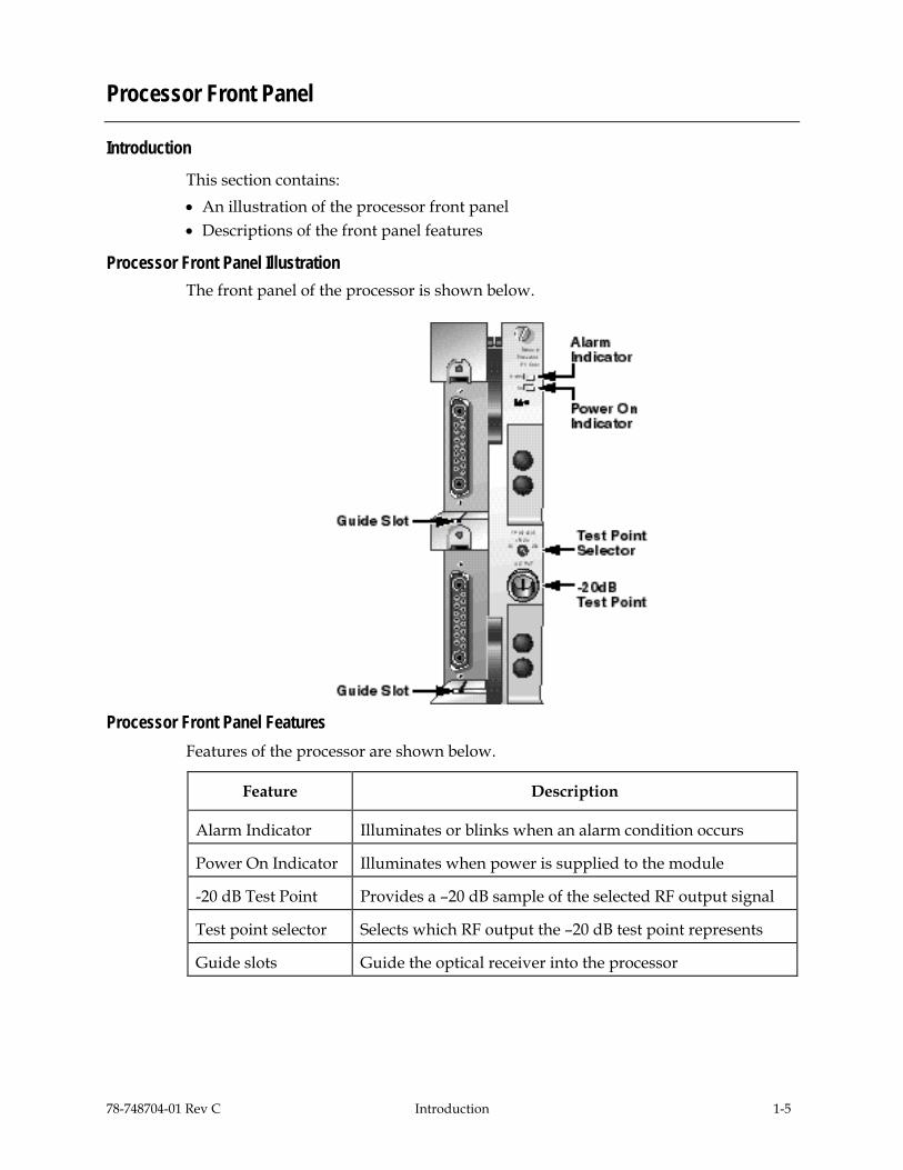
Processor Front Panel Illustration The front panel of the processor is shown below.
Processor Front Panel Features
Features of the processor are shown below.
Feature Description
Alarm Indicator Illuminates or blinks when an alarm condition occurs
Power On Indicator Illuminates when power is supplied to the module
-20 dB Test Point Provides a –20 dB sample of the selected RF output signal
Test point selector Selects which RF output the –20 dB test point represents
Guide slots Guide the optical receiver into the processor

1-6 Introduction 78-748704-01 Rev C
Processor Front Panel, Continued
Optical Receiver The processor houses two optical receivers that are independent. Each optical receiver detects an independent high-speed 2.5 Gbps optical signal and converts it to a PECL differential bit stream. This signal is then sent to the receive processor.
The optical receivers incorporate a single bicolor LED. The LED is an indicator of optical input and DC power presence to the optical receiver.
The bicolor LED status is shown in the table below.
Condition LED Status/Color
DC Power OFF/Optical Input OFF Off
DC Power ON/ Optical Input OFF Red
DC Power ON/Optical Input ON* Green
DC Power OFF/Optical Input ON Off
* Input light must be modulated. The LED may illuminate red even in the presence of CW light.

78-748704-01 Rev C Introduction 1-7
Processor Back Panel
Introduction Blind mate connectors on the back of the processor allow for easy installation of the processor into the chassis.
Back Panel Connectors The chassis provides:
• RF signal output connection
• Electrical power input connection
• Alarm communications connection
• Status monitoring communications
• Communications and control connections
Power and Communications Connector The power and communications connector on the back of the module mates with a connector inside of the chassis and supplies power from the chassis to the processor. The 110-pin connector also routes alarm and status monitoring information from the processor to the chassis.

1-8 Introduction 78-748704-01 Rev C
Optical Receiver Front Panel
Introduction This section contains: • An illustration of the optical receiver front panel • Descriptions of the front panel features
Optical Receiver Front Panel Illustration The front panel of an optical receiver is shown below
Optical Receiver Front Panel Features The features of the optical receiver front panel are described below.
Part Function
LED indicator (bicolor) • Illuminates red when an alarm condition occurs • Illuminates green when operation is normal
Optical input Connects the input optical fiber to the optical receiver

78-748704-01 Rev C Introduction 1-9
Processor Configuration Summary
Introduction The processor is shipped from the factory with operational parameters set to factory defaults. However, you may choose to configure the operating parameters so that they are best suited for your application.
Configuration and Monitoring Methods The table below shows the methods that can be used to configure and monitor the processor.
Method Description
Prisma II ICIM If an ICIM is installed in the chassis, it can be used to configure and monitor Prisma II application modules within its domain.
For instructions on operating this module using an ICIM, refer to Chapter 3, Operation Using the ICIM.
LCI software LCI running on a locally connected PC can be used to configure operating parameters of Prisma II modules.
For instructions on operating this module using LCI, refer to Chapter 4, Operation Using LCI.
TNCS software If an ICIM is installed, TNCS can be used to configure and monitor all functions of the Prisma II modules.
For instructions on operating this module using TNCS, see the manual that was shipped with the TNCS software, TNCS Administrator Software User’s Guide, part number 730201.
Parameter Configuration Summary Using any of the methods described above, you can configure the following parameters: • Activation of each optical receiver • Redundancy options • Attenuation of all RF outputs • Muting of all RF outputs
For detailed information on configuring this module, see Chapter 3, Operation Using the ICIM or Chapter 4, Operation Using LCI.

1-10 Introduction 78-748704-01 Rev C
Processor Configuration Options
Introduction The following processor options are user-configurable. • Optical receivers • RF output (muting) • Attenuation • Alarms • Test point selector and –20 dB test point • Redundant mode • External connections
These options can be restored to the factory default at any time.
Optical Receivers Both Prisma II bdr Optical Receivers may be configured to Active or Idle. The default setting is Active. When idle, an optical receiver’s output is muted, and alarms associated with the optical receiver are disabled.
RF Output (Muting) The processor can be configured to automatically or manually mute the RF output of individual channels 1A, 2A, 1B, and 2B. The default setting is Auto.
When an optical receiver is configured to Auto and is configured for internal or external redundancy, the processor determines whether each RF output should be muted based on alarms, such as missing optical receiver or loss of signal.
The processor can also be configured to manually mute RF output of individual channels. If RF output is configured to: • On, the channel’s RF output is not muted. • Off, the channel’s RF output is muted.
For more information on redundancy, see Redundant Mode later in this section.
Attenuation The amount of attenuation for each of the four RF output channels of the processor can be individually configured. • Using the ICIM, the RF output of channels 1A, 2A, 1B, and 2B can be individually
attenuated over a range of 0 dB to 10 dB in 0.5 dB steps. • Using LCI or TNCS, each RF output can be individually attenuated over a range of
0 dB to 10 dB in 0.1 dB steps. The default setting is 0 dB.

78-748704-01 Rev C Introduction 1-11
Processor Configuration Options, Continued
Alarms While this module contains no user-configurable alarm thresholds, some alarms may occur because of user-configurable settings or user action. The following are several examples of when an alarm can occur. • All outputs are muted • An optical receiver is removed when in redundant mode • Optical input cables are disconnected
Alarm conditions for specific parameters are labeled as Major, Minor, or Fault. Major and minor alarms designate if the parameter in alarm is of too high a value (MajorH) or too low a value (MajorL).
Major alarms produce a constant, illuminated red LED on the processor front panel, while minor alarms produce a blinking red LED. Alarm conditions can be investigated using the ICIM, LCI software, or TNCS software.
For additional information, refer to: • Check Processor Alarms Using the ICIM in Chapter 3 • Check Processor Alarms in Chapter 4 • Chapter 3, Operation Using the ICIM • Chapter 4, Operation Using LCI
Test Point Selector and -20 dB Test Point The processor front panel houses a test point selector and a -20 dB test point. The test point selector configures which RF input (1A, 2A, 1B, or 2B) the –20 dB test point represents. The test point provides a –20 dB sample of the selected RF input signal.

1-12 Introduction 78-748704-01 Rev C
Processor Configuration Options, Continued
Redundant Mode Both optical receivers installed in the processor may be configured to operate as either a Master, Internal, or External optical receiver as explained below and illustrated on the following pages.
Receiver Type
Description
Master The primary optical receiver. You can configure one, both, or neither of the optical receivers in the same processor as Master. • If both optical receivers in the same processor are configured as
Master, they have no internal backup and can only be backed-up by an identical optical receiver configured as External.
• If only one is configured as Master, the other optical receiver in that processor may also operate in one of the two redundant modes listed below.
• If neither optical receiver in a processor is configured as Master, they must operate in one of the two redundant modes listed below.
Master is the default setting.
Internal Internally redundant to an optical receiver located in the same processor. • With one optical receiver configured to Master, the other optical
receiver in the same processor can be configured as Internal (internally redundant), providing backup to the master optical receiver.
• When configured to Internal, an optical receiver’s output is activated only if the master optical receiver in the same processor fails. Two optical receivers in the same processor cannot be configured to Internal, as they would both be internal redundant with no master to back-up. Two optical receivers in the same processor configured to Internal will generate an RdnInvld alarm on the ICIM and an Invalid Redundant Receiver alarm when using LCI or TNCS software.
External Externally redundant to an optical receiver located outside of the processor. You can configure one, or both, or neither of the optical receivers in the same processor as External. When configured to External, an optical receiver is redundant to an optical receiver located in a separate processor. When configured as External, the optical receiver’s output is activated only if the master optical receiver located in the other processor fails.

78-748704-01 Rev C Introduction 1-13
Processor Configuration Options, Continued
External Connections To connect an optical receiver configured as External in the processor to an optical receiver outside of the processor, you must make proper electrical connections. To connect an optical receiver configured as External to an optical receiver in the same chassis, you must make a connection from the ALARMS OUT connector to the ALARMS IN connector located on the chassis. To connect an optical receiver configured as External in the processor to an optical receiver outside of the chassis, you must make a connection from the ALARMS OUT connector on the Connector Interface Panel of the chassis containing the master optical receiver to the ALARMS IN connector on the Connector Interface Panel of the chassis containing the optical receiver configured as External.
Factory Default Restoration After initialization, you can restore the processor’s factory default configuration at any time. An ICIM is required to implement the restore function. The Restore Factory Defaults command is an item in the processor’s MFG. DATA menu.
For details about the ICIM, the MFG. DATA menu, and the required user password, refer to Chapter 3, Operation Using the ICIM.
1-14 Introduction 78-748704-01 Rev C
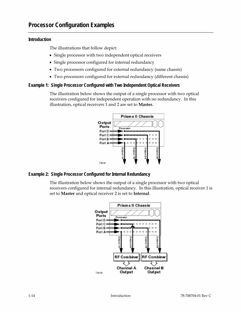
Processor Configuration Examples
Introduction The illustrations that follow depict: • Single processor with two independent optical receivers • Single processor configured for internal redundancy • Two processors configured for external redundancy (same chassis) • Two processors configured for external redundancy (different chassis)
Example 1: Single Processor Configured with Two Independent Optical Receivers The illustration below shows the output of a single processor with two optical receivers configured for independent operation with no redundancy. In this illustration, optical receivers 1 and 2 are set to Master.
Example 2: Single Processor Configured for Internal Redundancy The illustration below shows the output of a single processor with two optical receivers configured for internal redundancy. In this illustration, optical receiver 1 is set to Master and optical receiver 2 is set to Internal.

78-748704-01 Rev C Introduction 1-15
Processor Configuration Examples, Continued
Example 3: Two Processors Configured for External Redundancy (Same Chassis) The illustration below shows the output of a system with two processors in the same chassis configured for external redundancy. In this illustration, each processor has two optical receivers. Both optical receivers in processor 1 are set to Master and both optical receivers in processor 2 are set to External.
Example 4: Two Processors Configured for External Redundancy (Different Chassis) The illustration below shows the output of a system with two processors in different chassis configured for external redundancy. In this illustration, each processor has two optical receivers. Both optical receivers in processor 1 are set to Master and both optical receivers in processor 2 are set to External.

78-748704-01 Rev C Installation 2-1
Chapter 2 Installation
Overview
Introduction This chapter contains instructions, site requirements, equipment, and tools needed to install the Prisma II bdr 2:1 Dual Receive Processor and Prisma II bdr Optical Receivers.
Qualified Personnel
WARNING: Allow only qualified personnel to install, operate, maintain, or service this product. Otherwise, personal injury or equipment damage may occur.
In This Chapter This chapter contains the following topics.
Topic See Page
Prepare for Installation 2-2
Site Requirements 2-3
Connect RF Cables to the Chassis 2-6
Install the Processor in the Chassis 2-8
Connect Optical Cables 2-10
Install Optical Receivers in the Processor 2-13
Connect Multiple Chassis 2-15
Alarm I/O Connections 2-16
Prisma II Redundancy Interface Panel Overview 2-21
Interface Panel Features 2-22
Interface Panel Installation and Connections 2-23
Master/Slave Connections Overview 2-26

2-2 Installation 78-748704-01 Rev C
Prepare for Installation
Introduction Before you begin, make sure the module is in good condition and that you have the tools and equipment listed below.
Unpacking and Inspecting the Module
As you unpack the module, inspect it for shipping damage. If you find any damage, contact Cisco Services.
Required Equipment and Tools The following table shows the equipment and tools required to install the module.
You need . . . To . . .
a chassis with power supply provide housing, power, and input/output connections to the module.
two optical cables with connectors carry optical input signals.
four 75-ohm RF cables with F-type connectors
carry RF output signals.
3/8-in. flat-blade screwdriver secure the module in the chassis.
a 7/16-in. open-end wrench secure RF cables to the connectors on the chassis.
78-748704-01 Rev C Installation 2-3
Site Requirements
Introduction Before you begin, make certain that your installation site meets the requirements discussed in this section.
Access Requirements Ensure that only authorized personnel have access to this equipment. Otherwise, personal injury or equipment damage may occur.
WARNING: Use this product in locations that restrict access to all persons who are not authorized. Otherwise, personal injury or equipment damage may occur.
Equipment Rack To install the modules, your site should be equipped with an Electronics Industry Association (EIA) equipment rack that properly houses the chassis with proper spacing for air circulation. For instructions on installing the chassis in the rack, refer to the Prisma II Chassis Installation and Operation Guide, part number 713375.
Operating Environment
CAUTION:
Avoid damage to this product! Operating this product above the maximum operating temperature specified voids the warranty.
Follow these recommendations to maintain an acceptable operating temperature.
• Temperature inside the rack must be between -40°C and 65°C (-40°F and 149°F). • Keep cooling vents clear and free of obstructions. • Provide a non-condensing environment • Provide ventilation, as needed, using one or more of the following methods. − Air-deflecting baffles − Forced-air ventilation − Air outlets above enclosures

2-4 Installation 78-748704-01 Rev C
Site Requirements, Continued
Electrical Power The Prisma II modules receive electrical power from the Prisma II Chassis via the Prisma II power supplies. For specific information concerning chassis power requirements and power supply installation, see the guide that was shipped with the chassis, the Prisma II Chassis Installation and Operation Guide, part number 713375.
Chassis Slot Availability The Prisma II bdr 2:1 Dual Receive Processor is a double-wide module. It may only be installed in slots 5 through 16. Slots 15 and 16 are usually reserved for the Intelligent Communications Interface Module (ICIM), if installed. However, if an ICIM is not installed in slots 15 and 16, this processor or any other module(s) could be installed in those slots.
Power Supply Installation Slot Restrictions (Slots 1 through 4 ) Important: Slots 1 through 4 of the chassis are reserved exclusively for the Prisma II primary and redundant power supplies. If a redundant power supply is not installed, this module must not be installed in the redundant power supply slots.
If only one power supply is installed, a Prisma II Power Supply Blank, part number 716308, must be installed in the unused power supply slots.
Front and Rear Access Chassis Styles The chassis has power inlets, RF input and output ports, and other connectors that are located on the connector interface panel. This panel may be located on the front (front access) or rear (rear access) of the chassis, depending on the system you have purchased. Regardless of their location, these connections are labeled the same, serve the same function, and are made in the same manner.
For more detailed information concerning the connector interface panel, see the guide that was shipped with the chassis, the Prisma II Chassis Installation and Operation Guide, part number 713375.

78-748704-01 Rev C Installation 2-5
Site Requirements, Continued
Rear Access Chassis
The rear access chassis is shown here.
Front Access Chassis
The front access chassis is shown here.
2-6 Installation 78-748704-01 Rev C
Connect RF Cables to the Chassis
Introduction The following instructions explain how to make the RF cable connections for the processor.
Connecting the RF Cables Follow these steps to connect the RF cables to the chassis.
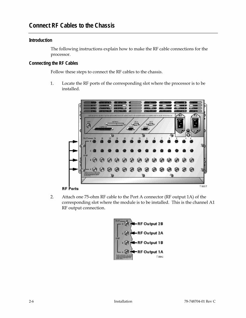
1. Locate the RF ports of the corresponding slot where the processor is to be installed.
2. Attach one 75-ohm RF cable to the Port A connector (RF output 1A) of the corresponding slot where the module is to be installed. This is the channel A1 RF output connection.

78-748704-01 Rev C Installation 2-7
Connect RF Cables to the Chassis, Continued
3. Attach the other 75-ohm RF cables to the Port B connector (RF output 1B), Port C (RF output 2A), and Port D (RF output 2B) connectors of the corresponding slot where the processor is to be installed
4. Route the RF cables to the appropriate RF destinations.
5. If F-connectors are installed, use a 7/16-in. open-end wrench to secure both cables to the connectors at the chassis.
6. Proceed to the next section, Install the Processor in the Chassis.

2-8 Installation 78-748704-01 Rev C
Install the Processor in the Chassis
Introduction For best results, install the processor into the chassis before installing the optical receivers into the processor.
If desired, the processor can be installed with the chassis powered up.
Installing the Processor Follow these steps to install the processor in the chassis.
1. Locate the fiber guides at the bottom of the chassis and the module guide slots inside the chassis as shown in the following illustration.
2. Align the ridges on the top and bottom of the processor with the module guide slots located on the chassis. Module ejectors must be fully extended when inserting the processor.
78-748704-01 Rev C Installation 2-9
Install the Processor in the Chassis, Continued
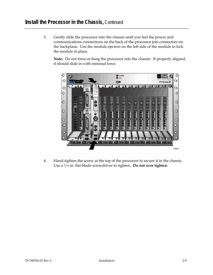
3. Gently slide the processor into the chassis until you feel the power and communications connections on the back of the processor join connectors on the backplane. Use the module ejectors on the left side of the module to lock the module in place.
Note: Do not force or bang the processor into the chassis. If properly aligned, it should slide in with minimal force.
4. Hand-tighten the screw at the top of the processor to secure it in the chassis. Use a 3/8-in. flat-blade screwdriver to tighten. Do not over tighten.

2-10 Installation 78-748704-01 Rev C
Connect Optical Cables
Introduction The following instructions explain how to connect optical cables to a processor and optical receivers.
Fiber Fish Tool Overview The fiber fish tool that was shipped with the chassis is used to pull (“fish”) an optical cable from the rear of the chassis to the front of the chassis so the cable can be connected to an optical connector on the front panel of a module.
At the end of the fiber fish tool is a small hook that allows you to hold an optical cable so that you can pull it through to the front of the chassis.

78-748704-01 Rev C Installation 2-11
Connect Optical Cables, Continued
Connecting an Optical Cable to the Processor Before proceeding, place a protective cap over the end of the cable to protect it while it is being pulled. Using a protective cap is generally a good idea when handling a cable at any time.
WARNING:
Avoid damage to your eyes! Do not look into any optical connector while the system is active. Even if the unit is off, there may still be hazardous optical levels present.
Follow these steps to pull the cable to the front of the chassis.
1. While facing the front of the chassis, insert the fiber fish tool through the slot located just above the bottom of the chassis.
2. At the rear of the chassis, locate the appropriate optical cable.
3. Insert the optical cable into one of the notches on the fiber fish tool.
4. Pull the fiber fish tool (with cable attached) to the front of the chassis.
5. Disengage the cable from the fiber fish tool and remove the protective cap from the cable.
6. Attach the cable to the appropriate connector on the processor front panel.
2-12 Installation 78-748704-01 Rev C
Connect Optical Cables, Continued
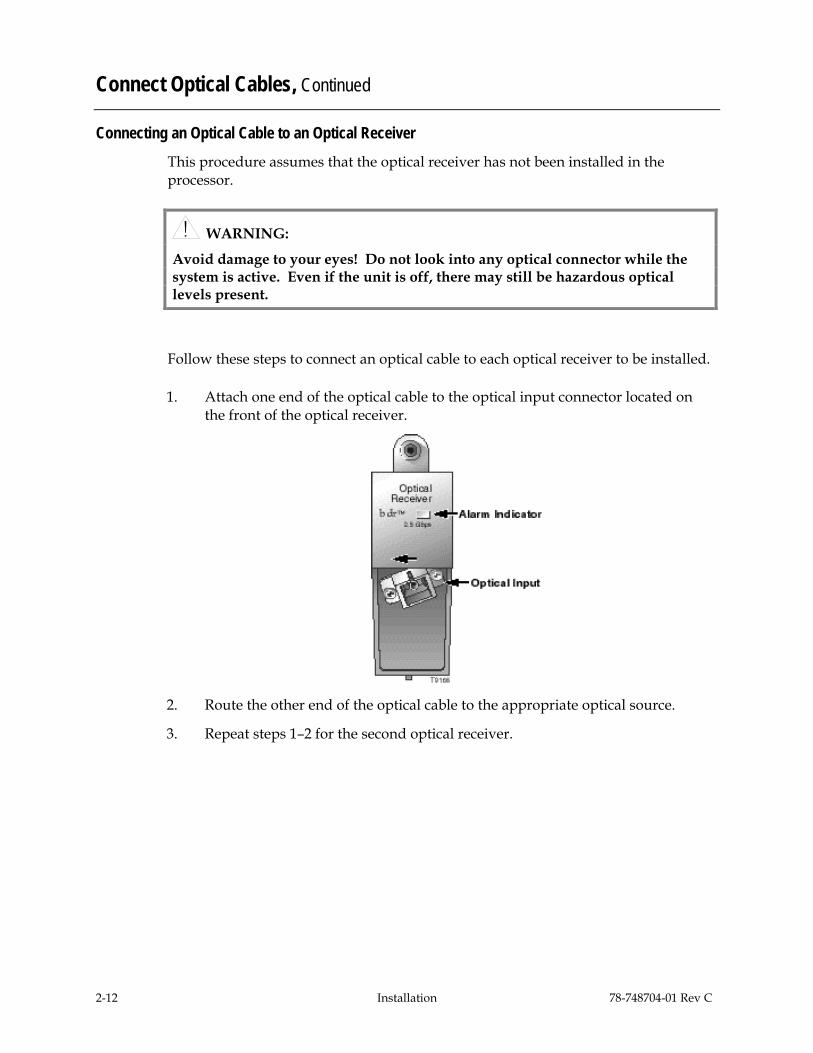
Connecting an Optical Cable to an Optical Receiver This procedure assumes that the optical receiver has not been installed in the processor.
WARNING:
Avoid damage to your eyes! Do not look into any optical connector while the system is active. Even if the unit is off, there may still be hazardous optical levels present.
Follow these steps to connect an optical cable to each optical receiver to be installed.
1. Attach one end of the optical cable to the optical input connector located on the front of the optical receiver.
2. Route the other end of the optical cable to the appropriate optical source.
3. Repeat steps 1–2 for the second optical receiver.

78-748704-01 Rev C Installation 2-13
Install Optical Receivers in the Processor
Introduction For best results, install the processor in the chassis before installing the optical receiver in the processor.
Installing the Optical Receiver Follow these steps to install the optical receiver in the processor.
1. Align the ridges on the top and bottom of the optical receiver with the guide slots located on the processor.
2. Gently slide the optical receiver into the processor until you feel the power and communications connections on the back of the module join connectors on the processor. Use the thumbscrew on the top of the optical receiver to lock it in place.

2-14 Installation 78-748704-01 Rev C
Install Optical Receivers in the Processor, Continued
3. Repeat steps 1–2 for the second optical receiver.
Result: Both optical receivers are installed.
78-748704-01 Rev C Installation 2-15
Connect Multiple Chassis
Introduction The Prisma II platform allows an ICIM to be located in one chassis to control application modules located in several other chassis. This communication “daisy-chain” can be enabled by connecting cables to the ICIM IN and ICIM OUT connectors located on the connector interface panel of the chassis.
Note: An ICIM can control a maximum of 82 modules. Depending on your application, this is typically six or seven chassis to a rack. Do not exceed these limits.
Cabling Requirements The cable required for both ICIM IN and ICIM OUT connections is a standard “off the shelf” serial extension cable, DB-9 female to DB-9 male, with connectors that are a serial 9-pin D-shell (EIA 574/232).
This cable can be purchased at your local computer store or from Cisco. The Cisco part number for a 6-foot serial extension cable is 180143.
Connecting the Chassis Follow these steps to make chassis-to-chassis ICIM IN and ICIM OUT connections.
1. Connect the serial extension cable from the ICIM OUT of the chassis containing the ICIM to the ICIM IN connector of the second chassis.
2. Connect a serial extension cable from the ICIM OUT of the second chassis to the ICIM IN of the third chassis.
3. Continue this “daisy-chain” connection until all desired chassis are connected.
Notes: • All chassis connected in the daisy-chain must be powered and have a fan tray
installed. A chassis that is connected but is either not powered or does not have a fan tray installed will cause faulty operation of the ICIM.
• All chassis connected in the daisy-chain must have a unique chassis ID number.
Additional Information For more information on chassis-to-chassis communications, including connections for TNCS and external alarm connections, see Communication Connections in Chapter 2 of the Prisma II Chassis Installation and Operation Guide, part number 713375.

2-16 Installation 78-748704-01 Rev C
Alarm I/O Connections
Introduction The following pages define the ALARMS IN and ALARMS OUT connectors on the Prisma II chassis. Wiring alarm contacts for external redundancy is also explained.
ALARMS IN Connector The ALARMS IN connector on the Prisma II chassis is a DB-37 female connector.
The table below shows connections for the ALARMS IN connector on the chassis.
Chassis Slot
ALARMS IN Pin #
Backplane Name Function
Fan Tray 20 FAN_TEST See notes at end of table
2 2 CNT_IN2_1 Slave input
21 CNT_IN2_2 Module dependent
Fan Tray 3 CNT_IN3_1 Slave input
22 CNT_IN3_2 Module dependent
4 4 CNT_IN4_1 Slave input
23 CNT_IN4_2 Module dependent
5 5 CNT_IN5_1 Slave input
24 CNT_IN5_2 Module dependent
6 6 CNT_IN6_1 Slave input
25 CNT_IN6_2 Module dependent
7 7 CNT_IN7_1 Slave input
26 CNT_IN7_2 Module dependent
8 8 CNT_IN8_1 Slave input
27 CNT_IN8_2 Module dependent

78-748704-01 Rev C Installation 2-17
Alarm I/O Connections, Continued
Chassis Slot
ALARMS IN Pin #
Backplane Name Function
9 9 CNT_IN9_1 Slave input
28 CNT_IN9_2 Module dependent
10 10 CNT_IN10_1 Slave input
29 CNT_IN10_2 Module dependent
11 11 CNT_IN11_1 Slave input
30 CNT_IN11_2 Module dependent
12 12 CNT_IN12_1 Slave input
31 CNT_IN12_2 Module dependent
13 13 CNT_IN13_1 Slave input
32 CNT_IN13_2 Module dependent
14 14 CNT_IN14_1 Slave input
33 CNT_IN14_2 Module dependent
15 15 CNT_IN15_1 Slave input
34 CNT_IN15_2 Module dependent
16 16 CNT_IN16_1 Slave input
35 CNT_IN16_2 Module dependent
N/A 1, 17, 18, 19, 36, 37 Not used N/A
Notes: • FAN_TEST is meant for factory use and is normally left open. Connecting this
input to ground turns off all the chassis fans. • The return path for all connections is chassis ground.
2-18 Installation 78-748704-01 Rev C
Alarm I/O Connections, Continued
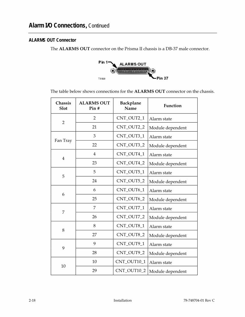
ALARMS OUT Connector The ALARMS OUT connector on the Prisma II chassis is a DB-37 male connector.
The table below shows connections for the ALARMS OUT connector on the chassis.
Chassis Slot
ALARMS OUT Pin #
Backplane Name Function
2 2 CNT_OUT2_1 Alarm state
21 CNT_OUT2_2 Module dependent
Fan Tray 3 CNT_OUT3_1 Alarm state
22 CNT_OUT3_2 Module dependent
4 4 CNT_OUT4_1 Alarm state
23 CNT_OUT4_2 Module dependent
5 5 CNT_OUT5_1 Alarm state
24 CNT_OUT5_2 Module dependent
6 6 CNT_OUT6_1 Alarm state
25 CNT_OUT6_2 Module dependent
7 7 CNT_OUT7_1 Alarm state
26 CNT_OUT7_2 Module dependent
8 8 CNT_OUT8_1 Alarm state
27 CNT_OUT8_2 Module dependent
9 9 CNT_OUT9_1 Alarm state
28 CNT_OUT9_2 Module dependent
10 10 CNT_OUT10_1 Alarm state
29 CNT_OUT10_2 Module dependent

78-748704-01 Rev C Installation 2-19
Alarm I/O Connections Continued
Chassis Slot
ALARMS OUT Pin #
Backplane Name Function
11 11 CNT_OUT11_1 Alarm state
30 CNT_OUT11_2 Module dependent
12 12 CNT_OUT12_1 Alarm state
31 CNT_OUT12_2 Module dependent
13 13 CNT_OUT13_1 Alarm state
32 CNT_OUT13_2 Module dependent
14 14 CNT_OUT14_1 Alarm state
33 CNT_OUT14_2 Module dependent
15 15 CNT_OUT15_1 Alarm state
34 CNT_OUT15_2 Module dependent
16 16 CNT_OUT16_1 Alarm state
35 CNT_OUT16_2 Module dependent
N/A 1, 17, 18, 19, 20, 36, 37 Not used N/A
Notes: • Return path for all connections is chassis ground • Alarm state indications: − Normal (with module installed): closed to ground − Critical alarm (or module not installed): open to ground
• Alarm relay rating: 2A 30 V DC (resistive)
2-20 Installation 78-748704-01 Rev C
Alarm I/O Connections, Continued
Wiring Alarm Contacts for External Redundancy When a critical alarm occurs in the master optical receiver, the master is disabled and the redundant optical receiver is enabled. If the redundant optical receiver is external (not in the same processor module as the master), the contacts from the master optical receiver’s pin on the ALARMS OUT connector must be wired to the contacts at the redundant optical receiver’s pin on the ALARMS IN connector of the chassis containing the redundant optical receiver. See the previous pages for pin locations.
Important: For external redundancy to function, the connection described above must be made when the redundant optical receiver is: • In the same chassis (but a different processor) as the master. • In a different chassis from the master.
Once the contacts are wired, care must be taken to ensure that the master and redundant optical receivers do not change slots. Otherwise, the ALARMS IN and ALARMS OUT connectors will need to be rewired.
Notes: • Any device configured as a master ignores its ALARMS IN contacts. • To verify proper wiring and configuration, simply unplug the master device and
make sure the redundant optical receiver turns on.

78-748704-01 Rev C Installation 2-21
Prisma II Redundancy Interface Panel Overview
Introduction The Prisma II Redundancy Interface Panel is an accessory to the Prisma II platform. The interface panel is intended to be used with the master/slave feature and the contact closure alarm feature of the Prisma II platform.
The terminals on the interface panel serve as extensions to the two DB-37 connectors labeled ALARM IN and ALARM OUT on the connector interface panel of the chassis.
The interface panel consists of the rack-mount panel, two cables, and jumper wire. The panel is to be mounted near the designated chassis in a 19-inch rack.
Slave Mode Operation in Prisma II Modules All Prisma II modules can be hard-wired to operate as a backup or slave module in a parallel redundant mode.
In this mode, a master and a slave module are interconnected and configured so that, if a critical fault occurs in the master, its output is turned off. When this happens, the slave module senses that the master is no longer operating and is automatically enabled. If the master's critical alarm disappears (for example, by replacing the module), the slave turns off and the master is re-enabled.
Prisma II modules are factory configured in master mode. To operate in slave mode, modules must be hard-wire connected and manually reconfigured using an ICIM, LCI software, or TNCS software.
Redundancy Interface Panel Illustration (Front) The front of the interface panel is shown below.
Redundancy Interface Panel Illustration (Rear) The rear of the interface panel is shown below.

2-22 Installation 78-748704-01 Rev C
Interface Panel Features
Introduction This section describes the various features of the Prisma II Redundancy Interface Panel.
Chassis Slot Numbers The Prisma II Chassis has sixteen slots. Each chassis slot has two alarm outputs and two alarm inputs. Slot numbers and the corresponding outputs and inputs are represented and labeled just below the terminal strips on the front of the Prisma II Redundancy Interface Panel.
Note: Slot 1 of the chassis is always reserved for the power supply and has no terminals on the panel. Slot 3 is represented on the interface panel, but is reserved for the fan tray. Therefore, the interface panel’s slot 3 spring terminals can only be used as alarm outputs or inputs for the fan tray.
Terminals Strips The front of the interface panel has four terminal strips that house spring terminals for each slot. The two left-side strips house two ALARM OUT terminals for each of the chassis slots 2 through 16, and the two right-side strips house two ALARM IN terminals for each of the chassis slots 2 through 16.
Spring Terminals The spring terminals are the points where the actual hard-wire connections between modules are made. Each spring terminal on the interface panel is an extension of a pin on the ALARMS OUT and ALARMS IN connectors on the chassis. Pressing the bottom lever of the spring terminal allows insertion of a jumper wire into the hole of the terminal. Releasing the lever secures the wire to the terminal.
Alarm Terminal Designations The ALARM OUT and ALARM IN terminal strips, chassis slot numbers, and A/B spring terminals are labeled just below the terminal strips on the front of the interface panel.
78-748704-01 Rev C Installation 2-23
Interface Panel Installation and Connections
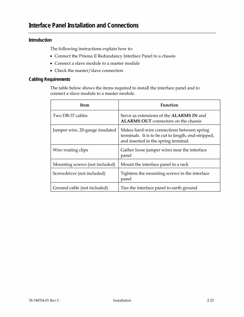
Introduction The following instructions explain how to: • Connect the Prisma II Redundancy Interface Panel to a chassis • Connect a slave module to a master module • Check the master/slave connection
Cabling Requirements The table below shows the items required to install the interface panel and to connect a slave module to a master module.
Item Function
Two DB-37 cables Serve as extensions of the ALARMS IN and ALARMS OUT connectors on the chassis
Jumper wire, 20-gauge insulated Makes hard-wire connections between spring terminals. It is to be cut to length, end-stripped, and inserted in the spring terminal.
Wire routing clips Gather loose jumper wires near the interface panel
Mounting screws (not included) Mount the interface panel in a rack
Screwdriver (not included) Tightens the mounting screws in the interface panel
Ground cable (not included) Ties the interface panel to earth ground

2-24 Installation 78-748704-01 Rev C
Interface Panel Installation and Connections, Continued
Installing the Interface Panel Follow these steps to install the interface panel.
1. Position the interface panel in the rack near the designated chassis.
2. Insert a mounting screw through each of the four mounting slots on the front of the interface panel, and then into the rack (screws are not included.)
3. Use an appropriate screwdriver to tighten each mounting screw until it is tight (screwdriver is not included).
4. Tie the interface panel to earth ground via the ground stud (ground cable is not included).
Important: Grounding the interface panel via the ground stud is especially important for ESD and EMC performance.
Connecting the Interface Panel to the Chassis Follow these steps to connect the interface panel to the chassis.
1. Connect the female end of one DB-37 cable to the male end ALARMS OUT connector on the chassis.
2. Connect the male end of the same DB-37 cable to the female end ALARM OUT connector on the rear of the interface panel.
3. Connect the male end of the second DB-37 cable to the female end ALARMS IN connector on the chassis.
4. Connect the female end of the second DB-37 cable to the male end ALARM IN connector on the rear of the interface panel.

78-748704-01 Rev C Installation 2-25
Interface Panel Installation and Connections, Continued
Connecting a Slave Module to a Master Module Follow these steps to connect a slave module to a master module using the interface panel.
Notes: • To configure a module as master or slave, use the ICIM, the LCI software, or TNCS
software as shown in the guide that was shipped with the specific Prisma II module.
• For information about typical master/slave connections, refer to Master/Slave Connections Overview later in this chapter.
1. On the ALARM OUT strip at the front of the interface panel, locate the slot number representing the chassis slot location of the master module. Connect one end of a jumper wire to spring terminal A of that slot number.
2. Connect the other end of the same jumper wire to the A terminal of the slot of the slave module on the ALARMS IN connector. This connection may or may not be on the same interface panel.
3. Repeat steps 1 and 2 for the B terminals of both the master and the slave module’s ALARM IN and ALARM OUT terminal strips.
4. Upon connecting all wires, adhere the wire routing clips to the interface panel and connect the wires onto the clips.
Checking the Master/Slave Connection Follow these steps to verify that the master/slave connection is operating properly.
1. Ensure that all master and slave modules are installed, power is applied to your system, and all cable connections between the chassis and the interface panel(s) are secure.
2. Verify that the primary module is configured to operate as a master and the backup module is configured to operate as a slave (or as externally redundant when connecting bdr processors).
3. Ensure that all jumper wires are securely connected to the proper terminals.
4. When the system is powered and properly configured, remove the master module and verify that the slave module turns on and begins operation. If the slave does not operate, review the installation and connection steps given in this section.
2-26 Installation 78-748704-01 Rev C
Master/Slave Connections Overview
Introduction This overview describes the: • Interface panel terminal strips • Typical master/slave jumper connections for modules in the same chassis and in
separate chassis
Interface Panel Terminal Strips On the interface panel terminal strips, all chassis slots except for slot 1 and slot 3 are available. Each chassis slot has two outputs (A and B) and two inputs (A and B) for communication of alarm information to or from other modules. However, on most Prisma II modules, the B output is disabled.
78-748704-01 Rev C Installation 2-27
Master/Slave Connections, Continued
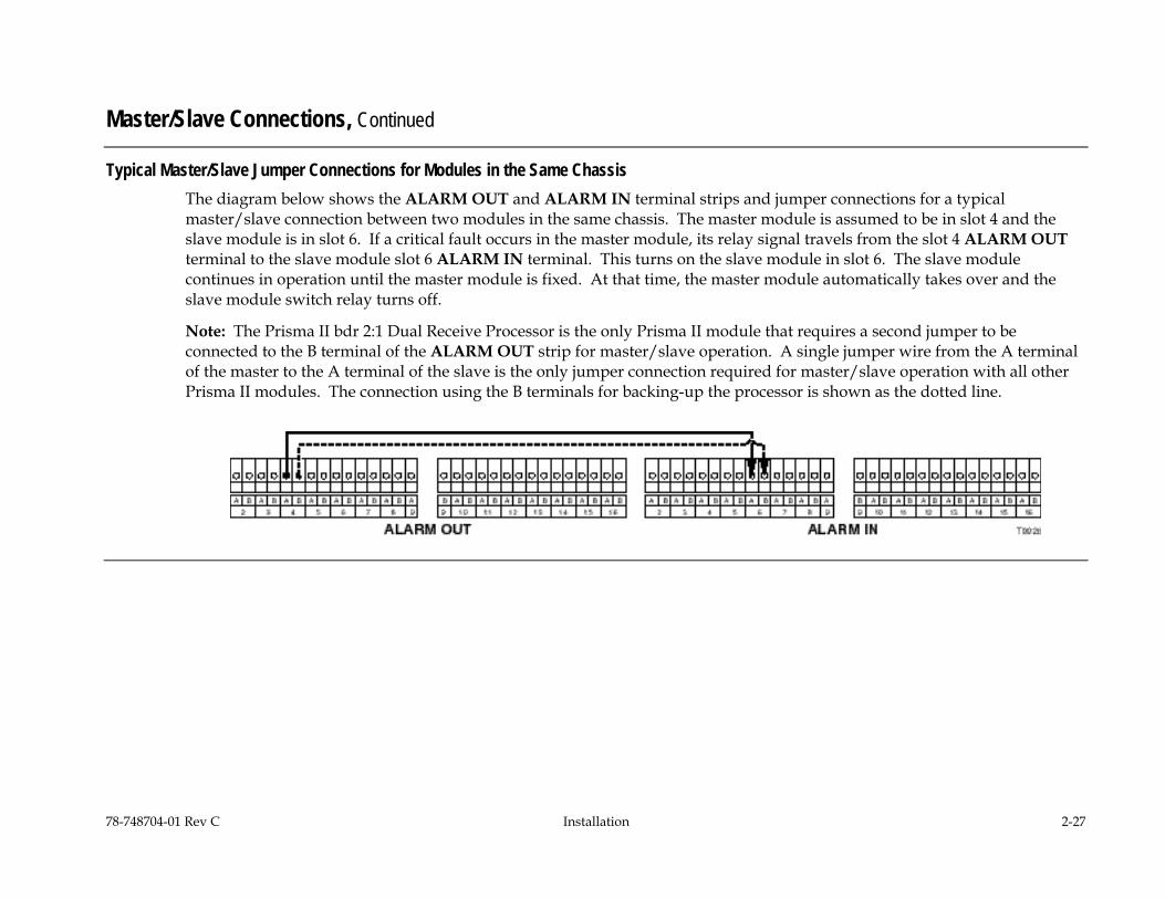
Typical Master/Slave Jumper Connections for Modules in the Same Chassis The diagram below shows the ALARM OUT and ALARM IN terminal strips and jumper connections for a typical master/slave connection between two modules in the same chassis. The master module is assumed to be in slot 4 and the slave module is in slot 6. If a critical fault occurs in the master module, its relay signal travels from the slot 4 ALARM OUT terminal to the slave module slot 6 ALARM IN terminal. This turns on the slave module in slot 6. The slave module continues in operation until the master module is fixed. At that time, the master module automatically takes over and the slave module switch relay turns off.
Note: The Prisma II bdr 2:1 Dual Receive Processor is the only Prisma II module that requires a second jumper to be connected to the B terminal of the ALARM OUT strip for master/slave operation. A single jumper wire from the A terminal of the master to the A terminal of the slave is the only jumper connection required for master/slave operation with all other Prisma II modules. The connection using the B terminals for backing-up the processor is shown as the dotted line.
2-28 Installation 78-748704-01 Rev C
Master/Slave Connections, Continued
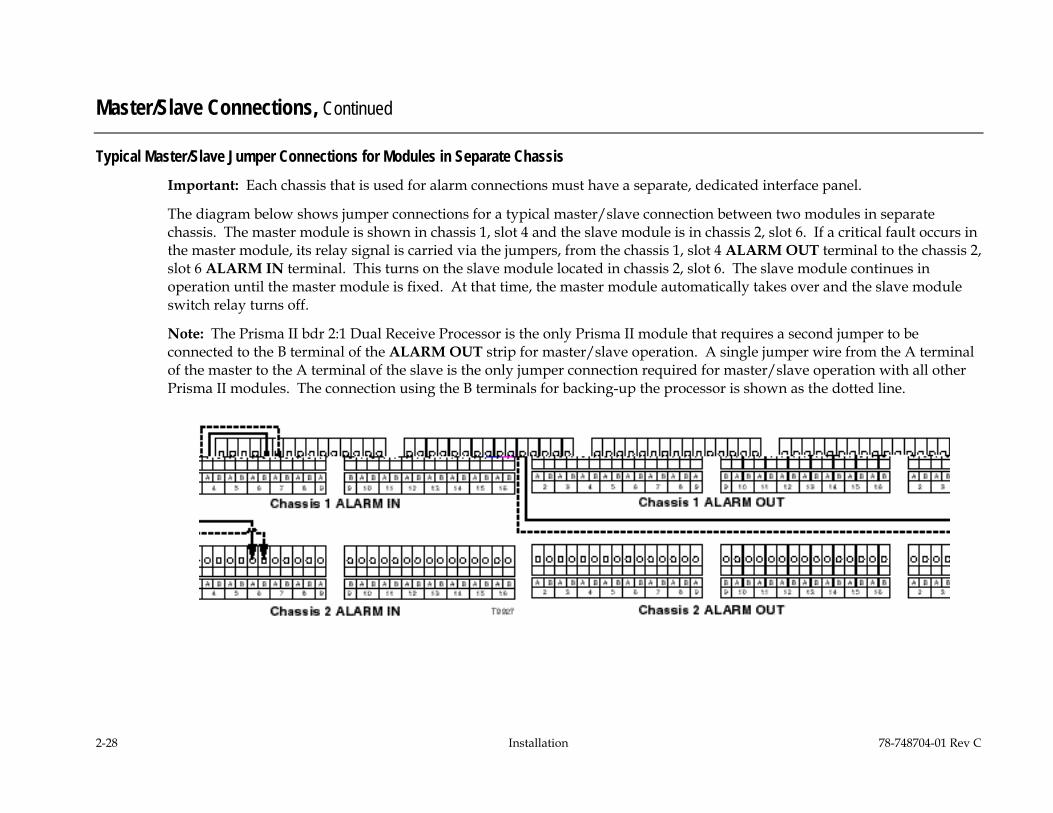
Typical Master/Slave Jumper Connections for Modules in Separate Chassis Important: Each chassis that is used for alarm connections must have a separate, dedicated interface panel.
The diagram below shows jumper connections for a typical master/slave connection between two modules in separate chassis. The master module is shown in chassis 1, slot 4 and the slave module is in chassis 2, slot 6. If a critical fault occurs in the master module, its relay signal is carried via the jumpers, from the chassis 1, slot 4 ALARM OUT terminal to the chassis 2, slot 6 ALARM IN terminal. This turns on the slave module located in chassis 2, slot 6. The slave module continues in operation until the master module is fixed. At that time, the master module automatically takes over and the slave module switch relay turns off.
Note: The Prisma II bdr 2:1 Dual Receive Processor is the only Prisma II module that requires a second jumper to be connected to the B terminal of the ALARM OUT strip for master/slave operation. A single jumper wire from the A terminal of the master to the A terminal of the slave is the only jumper connection required for master/slave operation with all other Prisma II modules. The connection using the B terminals for backing-up the processor is shown as the dotted line.
78-748704-01 Rev C Operation Using the ICIM 3-1
Chapter 3 Operation Using the ICIM
Overview
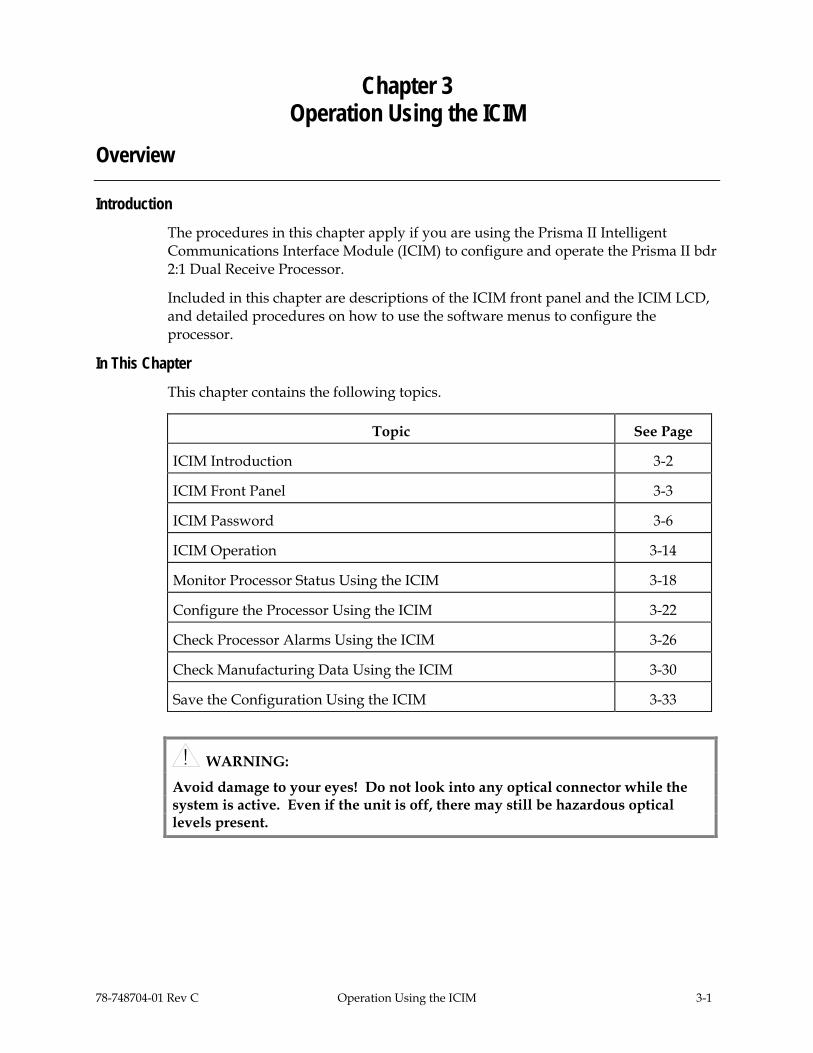
Introduction The procedures in this chapter apply if you are using the Prisma II Intelligent Communications Interface Module (ICIM) to configure and operate the Prisma II bdr 2:1 Dual Receive Processor.
Included in this chapter are descriptions of the ICIM front panel and the ICIM LCD, and detailed procedures on how to use the software menus to configure the processor.
In This Chapter This chapter contains the following topics.
Topic See Page
ICIM Introduction 3-2
ICIM Front Panel 3-3
ICIM Password 3-6
ICIM Operation 3-14
Monitor Processor Status Using the ICIM 3-18
Configure the Processor Using the ICIM 3-22
Check Processor Alarms Using the ICIM 3-26
Check Manufacturing Data Using the ICIM 3-30
Save the Configuration Using the ICIM 3-33
WARNING:
Avoid damage to your eyes! Do not look into any optical connector while the system is active. Even if the unit is off, there may still be hazardous optical levels present.

3-2 Operation Using the ICIM 78-748704-01 Rev C
ICIM Introduction
Introduction The ICIM functions as the user interface for the Prisma II application modules, as well as the interface between the Prisma II modules and the Transmission Networks Control Systems (TNCS) software. The ICIM allows local module configuration and status monitoring for up to 82 modules located in multiple chassis. The ICIM features easy-to-use software that is navigated using the numeric keypad and the LCD display.
Important: • Do not operate any Prisma II Chassis without a fan tray properly installed. If a fan
tray is not installed in the chassis, the ICIM will not communicate with any of the modules in the chassis.
• All chassis connected in a “daisy-chain” fashion must be powered and have a fan tray installed. A chassis that is connected but is either not powered or does not have a fan tray installed will cause faulty operation of the ICIM.
• All chassis connected in the daisy-chain must have a unique chassis ID number.
ICIM Block Diagram The ICIM is illustrated in the block diagram below.

78-748704-01 Rev C Operation Using the ICIM 3-3
ICIM Front Panel
Introduction This section contains: • An illustration of the ICIM front panel • Descriptions of the front panel features
ICIM Front Panel Illustration The following illustration shows the front panel of the ICIM.
3-4 Operation Using the ICIM 78-748704-01 Rev C
ICIM Front Panel, Continued
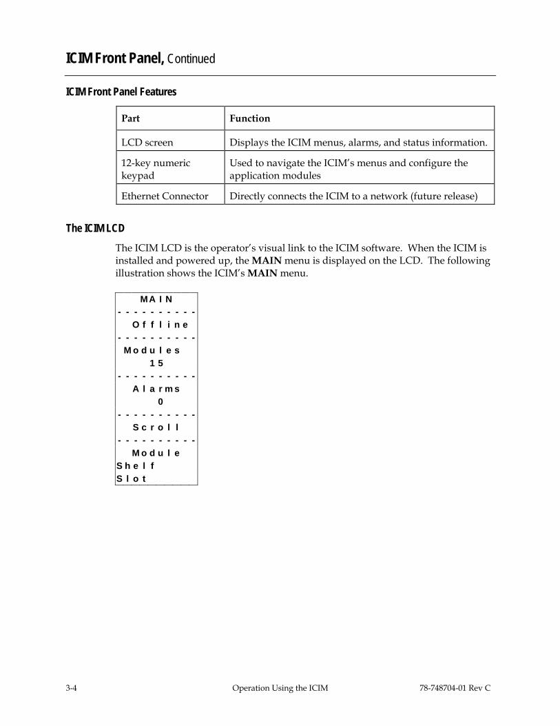
ICIM Front Panel Features
Part Function
LCD screen Displays the ICIM menus, alarms, and status information.
12-key numeric keypad
Used to navigate the ICIM’s menus and configure the application modules
Ethernet Connector Directly connects the ICIM to a network (future release)
The ICIM LCD The ICIM LCD is the operator’s visual link to the ICIM software. When the ICIM is installed and powered up, the MAIN menu is displayed on the LCD. The following illustration shows the ICIM’s MAIN menu.
M A I N - - - - - - - - - - O f f l i n e - - - - - - - - - - M o d u l e s 1 5 - - - - - - - - - - A l a r m s 0 - - - - - - - - - - S c r o l l - - - - - - - - - - M o d u l e
S h e l f S l o t
78-748704-01 Rev C Operation Using the ICIM 3-5
ICIM Front Panel, Continued
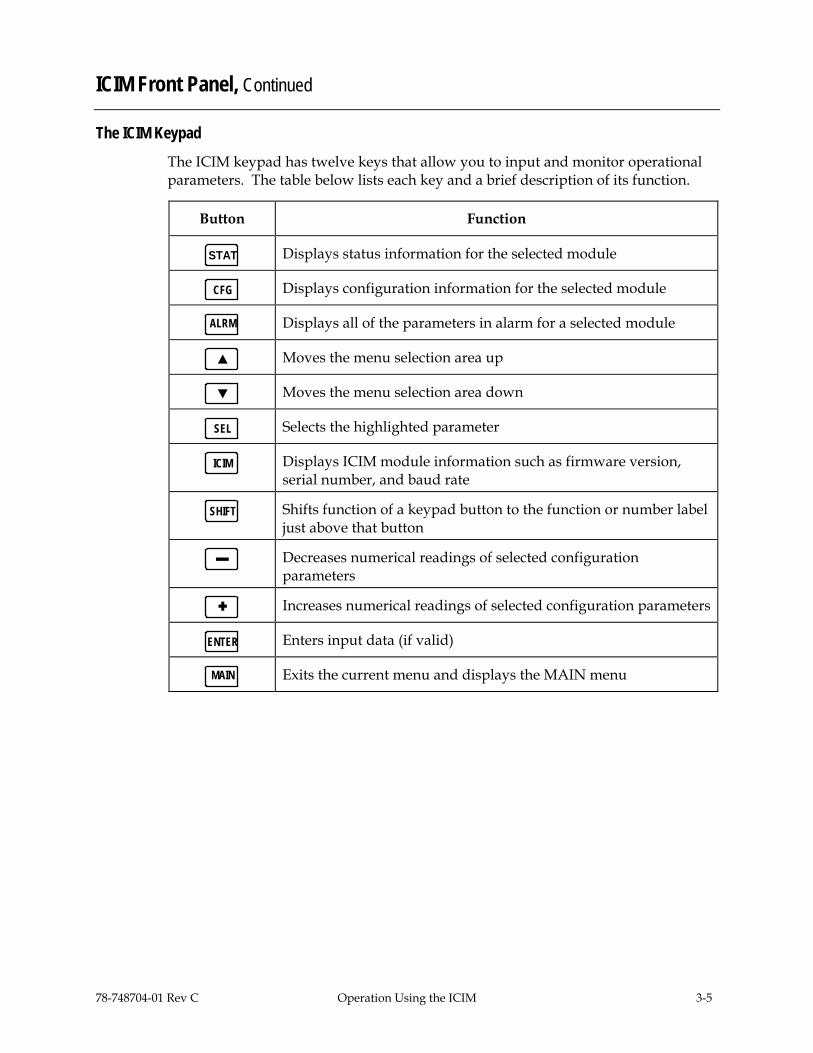
The ICIM Keypad The ICIM keypad has twelve keys that allow you to input and monitor operational parameters. The table below lists each key and a brief description of its function.
Button Function
STAT Displays status information for the selected module
CFG Displays configuration information for the selected module
ALRM Displays all of the parameters in alarm for a selected module
Moves the menu selection area up
Moves the menu selection area down
SEL Selects the highlighted parameter
ICIM Displays ICIM module information such as firmware version, serial number, and baud rate
SHIFT Shifts function of a keypad button to the function or number label just above that button
Decreases numerical readings of selected configuration parameters
Increases numerical readings of selected configuration parameters
ENTER Enters input data (if valid)
MAIN Exits the current menu and displays the MAIN menu

3-6 Operation Using the ICIM 78-748704-01 Rev C
ICIM Password
Introduction The ICIM allows you to send configuration commands, check alarms and operating status, and restore factory default settings in Prisma II modules. To ensure that no unauthorized changing of these parameters occurs, you have the option of using a password protection system.
Password authorization only applies to the configurable parameters. Status and alarm information is always available on the ICIM regardless of password implementation.
Password Protection System The table below shows the ICIM menu options available in the password protection system.
ICIM Menu Option
Description
User Psw A user-settable password. • Created, entered, and changed by the system operator(s) • Must be exactly eight digits, using only the 0-9 number keys
Change Psw Changes an existing user password
Disable Psw Disables the user password function
SA Psw A service password that is used by Cisco personnel only
Important: If you only want to monitor status and alarm data, skip the password function when it appears on the ICIM menu. You can access all module status and alarm information without a password. However, once a user password is entered, you are required to enter it every time you want to set configurable parameters to any module controlled by that ICIM. For more information, refer to the remaining pages in this section.

78-748704-01 Rev C Operation Using the ICIM 3-7
ICIM Password, Continued
Accessing the Password Function The Password menu allows you to create, enter, change, or disable the user password. It also allows service personnel to use the Cisco (SA) password.
Follow these steps to access the Password menu.
1. Press the ICIM key.
2. Use the key to scroll down until Password is highlighted.
3. Press the SEL key.
Results: • The Password menu is displayed. • User Psw is highlighted.
M A I N I C I M I C I M I C I M - - - - - - - - - - - - - - - - - - - - - - - - - - - - - - - - - - - - - O f f l i n e S h e l f 7 S h e l f 7 S h e l f 7 - - - - - - - - - S l o t 1 5 S l o t 1 5 S l o t 1 5 M o d u l e s - - - - - - - - - - - - - - - - - - - - - - - - - - - - 0 M f g D a t a M f g D a t a U s e r P s w A l a r m s - - - - - - - - - - - - - - - - - - - - - - - - - - - - 0 S A P s w - - - - - - - - - P a s s w o r d P a s s w o r d - - - - - - - - - - S c r o l l C h a n g e P s w - - - - - - - - - - - - - - - - - - - - - - - - - - - - - - - - - - - - - M o d u l e U p d a t e A d r U p d a t e A d r D i s a b l e
S h e l f P s w S l o t
Expired Password or Inactive Password Messages The entry of a valid user or SA password allows changes to system parameters for a period of 10 minutes. If more than 10 minutes have passed since your last keystroke, and you attempt to make any changes to system parameters, the menu displays Psw Expired. If, after more than 10 minutes you attempt to disable the password, the menu displays Failed, Password Not Active.
If either of these messages is displayed, you are required to re-enter the password. To re-enter the password, follow the procedure in Re-Entering a User Password later in this section.

3-8 Operation Using the ICIM 78-748704-01 Rev C
ICIM Password, Continued
Using Your Password for the First Time Follow these steps to enter a user password in an ICIM that has never had the user password function implemented.
1. Access the password function as shown in Accessing the ICIM Password Function earlier in this section.
2. Use the key to scroll down until Change Psw is highlighted.
3. Press the SEL key.
Result: Change Psw/Shift Off is displayed.
4. Press the SHIFT key to display Shift On. Then enter 8 digits as your user password, using the 0–9 number keys.
If at any time you input a digit that is incorrect or you wish to change a digit, use the CAN (Cancel) function by pressing the ALRM key to delete that digit.
5. Press the ENTER key.
Result: The ICIM updates the display to show if your password entry was accepted or rejected. If the entry was accepted, you are able to return to the MAIN menu.
6. If the password you entered is rejected, press the SHIFT key to return to the password function, then re-enter an 8–digit password using only the 0-9 number keys. Press the ENTER key.
Reasons for a user password to be rejected include: • Entering more than 8 digits for the password • Pressing keys other than the 0–9 number keys • Entering an incorrect password if a valid password has been entered

78-748704-01 Rev C Operation Using the ICIM 3-9
ICIM Password, Continued
Re-Entering a User Password If more than 10 minutes have passed since your last keystroke, and you attempt to make any changes to system parameters, the menu displays Psw Expired. If you attempt to disable the password, the menu displays Failed, Password Not Active. When either of these messages is displayed, you must re-enter the user password.
Follow these steps to re-enter a user password.
1. Access the password as described in Accessing the Password Function earlier in this section.
2. Press the SEL key.
Result: User Psw/Shift Off is displayed.
3. Press the SHIFT key to display Shift On. Then enter the 8 digits of the user password, using the 0–9 number keys.
If at any time you input a digit that is incorrect or you wish to change a digit, use the CAN (Cancel) function by pressing the ALRM key to delete that digit.
4. Press the ENTER key.
Result: The ICIM updates the display to show if your password entry was accepted or rejected. If the entry was accepted, you are able to return to the MAIN menu.

3-10 Operation Using the ICIM 78-748704-01 Rev C
ICIM Password, Continued
5. If the password you entered is rejected, press the SHIFT key to return to the password function, then re-enter your password. Press the ENTER key.
Reasons for a user password to be rejected include: • Entering more than 8 digits for the password • Pressing keys other than the 0–9 number keys • Entering an incorrect password if a valid password has been entered
I C I M I C I M I C I M I C I M - - - - - - - - - - - - - - - - - - - - - - - - - - - - - - - - - - - - - - - - S h e l f 7 S h e l f 7 S h e l f 7 S h e l f 7 S l o t 1 5 S l o t 1 5 S l o t 1 5 S l o t 1 5 - - - - - - - - - - - - - - - - - - - - - - - - - - - - - - - - - - - - - U s e r P s w U s e r P s w U s e r P s w U s e r P s w * * * * * * * * 1 2 3 4 * * * * 1 2 3 4 5 6 7 8 - - - - - - - - - - - - - - - - - - - - - - - - - - - - - - - - - - - - - - - - R e j e c t e d A c c e p t e d S h i f t O f f S h i f t O n S h i f t O f f S h i f t O f f

78-748704-01 Rev C Operation Using the ICIM 3-11
ICIM Password, Continued
Changing the User Password If the current user password has expired (more than 10 minutes have passed since your last keystroke), you must re-enter the current password before changing to a new one.
Important: The current user password must be active prior to changing it.
Follow these steps to change the user password.
1. Access the password function as shown in the procedure Accessing the Password Function earlier in this section.
2. Use the key to scroll down until Change Psw is highlighted.
3. Press the SEL key to select Change Psw.
4. When Change Psw /Shift Off is displayed, press the SHIFT key to display Shift On. Then enter the 8 digits of your new password, using the 0–9 number keys.
If you input a digit that is incorrect or wish to change a digit, use the CAN (Cancel) function by pressing the ALRM key to delete that digit.
5. Press the ENTER key.
Result: The ICIM updates the display to show if your password entry was accepted or rejected. If the entry was accepted, you are able to return to the MAIN menu.

3-12 Operation Using the ICIM 78-748704-01 Rev C
ICIM Password, Continued
6. If the new password you entered is rejected, press the SHIFT key to return to the password function, then re-enter the new 8–digit password. Press the ENTER key.
I C I M I C I M I C I M I C I M - - - - - - - - - - - - - - - - - - - - - - - - - - - - - - - - - - - - - - - - S h e l f 7 S h e l f 7 S h e l f 7 S h e l f 7 S l o t 1 5 S l o t 1 5 S l o t 1 5 S l o t 1 5 - - - - - - - - - - - - - - - - - - - - - - - - - - - - - - - - - - - - - - - - U s e r P s w C h a n g e P s w C h a n g e P s w C h a n g e P s w - - - - - - - - - - * * * * * * * * 8 7 6 5 4 3 2 1 S A P s w - - - - - - - - - - - - - - - - - - - - - - - - - - - - - - - - - - - - - - - - C h a n g e P s w - - - - - - - - - - D i s a b l e P s w S h i f t O f f S h i f t O n S h i f t O n

78-748704-01 Rev C Operation Using the ICIM 3-13
ICIM Password, Continued
Disabling the User Password If a user password has been entered, you may disable it at any time.
Important: The current password must be active prior to disabling it. If the current password has expired (more than 10 minutes have passed since your last keystroke), you must re-enter the password before disabling it.
Follow these steps to disable a user password.
1. Press the ICIM key.
2. Use the key to scroll down until Password is highlighted.
3. Press the SEL key.
4. Use the key to scroll down until Disable Psw is highlighted.
5. Press the SEL key to select Disable Psw.
6. If the current password is active, the menu displays Password Is Now Disabled. You can now make changes to parameters without any password.
7. If the current password has expired (more than 10 minutes have passed since your last keystroke), the menu displays Failed, Password Not Active. You must re-enter the current password and then repeat this procedure.
I C I M I C I M I C I M - - - - - - - - - - - - - - - - - - - - - - - - - - - - - - S h e l f 7 S h e l f 7 S h e l f 7 S l o t 1 5 S l o t 1 5 S l o t 1 5 - - - - - - - - - - - - - - - - - - - - - - - - - - - - - U s e r P s w - - - - - - - - - - S A P s w - - - - - - - - - - - - - - - - - - - - - - - - - - - - - C h a n g e P s w P a s s w o r d F a i l e d , - - - - - - - - - - I s N o w P a s s w o r d D i s a b l e D i s a b l e d N o t A c t i v e P s w S h i f t O f f S h i f t O f f
3-14 Operation Using the ICIM 78-748704-01 Rev C
ICIM Operation
Introduction Once the module is installed as described in Chapter 2, Installation, it runs without the aid of an operator. Unless alarms are generated or your system configuration changes, you should not need to adjust the module beyond the initial setup.
Accessing the ICIM LCD Contrast
To access the ICIM LCD contrast control from the MAIN menu, press the ICIM key. Use the key to increase or the key to decrease ICIM display contrast.
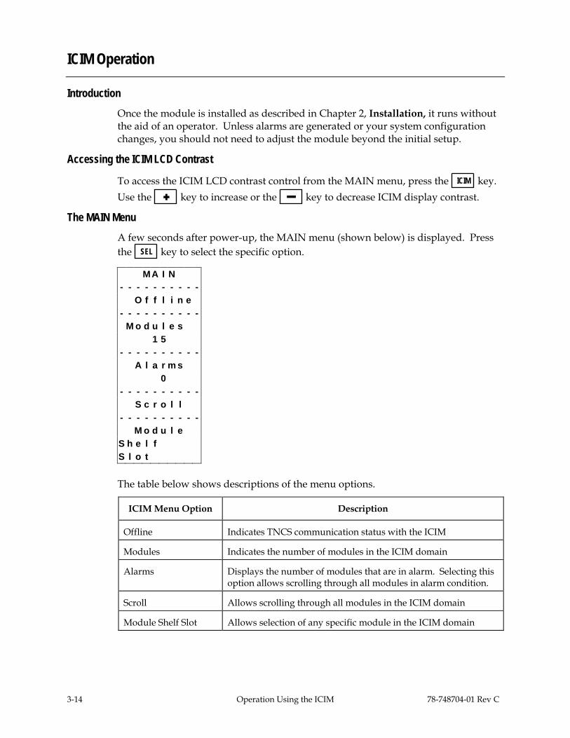
The MAIN Menu A few seconds after power-up, the MAIN menu (shown below) is displayed. Press the SEL key to select the specific option.
M A I N - - - - - - - - - - O f f l i n e - - - - - - - - - - M o d u l e s 1 5 - - - - - - - - - - A l a r m s 0 - - - - - - - - - - S c r o l l - - - - - - - - - - M o d u l e
S h e l f S l o t
The table below shows descriptions of the menu options.
ICIM Menu Option Description
Offline Indicates TNCS communication status with the ICIM
Modules Indicates the number of modules in the ICIM domain
Alarms Displays the number of modules that are in alarm. Selecting this option allows scrolling through all modules in alarm condition.
Scroll Allows scrolling through all modules in the ICIM domain
Module Shelf Slot Allows selection of any specific module in the ICIM domain

78-748704-01 Rev C Operation Using the ICIM 3-15
ICIM Operation, Continued
Prisma II ICIM Menu
To display the ICIM menu, press the ICIM key. The ICIM menu (shown below) is displayed. Press the SEL key to select the specific option.
I C I M I C I M I C I M - - - - - - - - - - - - - - - - - - - - - - - - - - - - - - S h e l f 7 S h e l f 7 S h e l f 7 S l o t 1 5 S l o t 1 5 S l o t 1 5 - - - - - - - - - - - - - - - - - - - - - - - - - - - - - - M f g D a t a M f g D a t a M f g D a t a - - - - - - - - - - - - - - - - - - - - - - - - - - - - - - P a s s w o r d P a s s w o r d P a s s w o r d - - - - - - - - - - - - - - - - - - - - - - - - - - - - - - U p d a t e A d r U p d a t e A d r U p d a t e A d r
The table below shows descriptions of the menu options.
ICIM Menu Option Description
Shelf Slot Displays the location of the ICIM module
Mfg Data Displays manufacturing data about the ICIM
Password Allows you to enter, change, or disable a system password. See The ICIM Password earlier in this chapter.
Update Adr If the Chassis ID number switch has been changed, you must highlight the Update Adr menu and press the SEL key for the ICIM to recognize the change

3-16 Operation Using the ICIM 78-748704-01 Rev C
ICIM Operation, Continued
Prisma II MAIN Menu Structure Pressing the MAIN key initiates the MAIN software menu. Pressing the ICIM key initiates the ICIM software menu. The MAIN and ICIM software structures are shown below.
ICIMShelfSlot
Mfg. DataSerial NumHW VersionSW Version
SW DateModule TypeMAC Addr
In Service Hrs
PasswordUser PswSA Psw
Change PswDisable Psw
UpdateAddress
MAINOffline
ModulesAlarmsScroll
ModuleShelfSlot
MAIN Key ICIM Key

78-748704-01 Rev C Operation Using the ICIM 3-17
ICIM Operation, Continued
Processor Software Menu Structure From the MAIN or SCROLL menus, you can navigate to the processor MODULE menu. From the MODULE menu, press the STAT , CFG , or ALRM key to display the
desired parameter menu.
MFG. DATAModule Type
Serial #Date Code
Sw VerScript Ver
In Service HrsSpec Data
RestoreFactoryDefaults STATUS
ExtPower+1_8VInt+3_3VInt
ProcTempRcv1PresRcv1TypeRF_Out1ARF_Out1BRcv2PresRcv2TypeRF_Out2ARF_Out2B
Recv1RednRcv1RFOut_1ARFOut_1BRFAttn1ARFAttn1B
Recv2RednRcv2RFOut_2ARFOut_2BRFAttn2ARFAttn2B
CONFIGRecv1
RednRcv1RFOut_1ARFOut_1BRFAttn1ARFAttn1B
Recv2RednRcv2RFOut_2ARFOut_2BRFAttn2ARFAttn2B
STATKey
MODULEMenu
MAIN orSCROLL
Menu
CFGKey
MAIN orSCROLL
Menu
MODULEMenu
MAIN orSCROLL
Menu
MODULEMenu
ALRM Key
ALARMSDCPowerProcTempRdnInvldRcv1InstRcv1Bias
Rcv1_LOSRcv1DataRcv2InstRcv2Bias
Rcv2_LOSRcv2Data

3-18 Operation Using the ICIM 78-748704-01 Rev C
Monitor Processor Status Using the ICIM
Introduction The ICIM allows you to monitor the operating status of parameters.
STATUS Parameters The table below describes the monitored status parameters for this processor.
Parameter Units Function
ExtPower OK or Fault Indicates DC power supply voltage status.
+1_8VInt V Internal voltage level-nominal 1.8 V DC.
+3_3VInt V Internal voltage level-nominal 3.3 V DC.
ProcTemp °C Indicates processor temperature.
Rcv1Pres Yes or No Indicates if receiver 1 is installed.
Rcv1Type 1 or 2 Indicates what type receiver is installed. 1 = standard range receiver - PIN 2 = extended range receiver - APD
RF_Out1A RF_Out1B
On or Off Indicates whether the actual output of RF channels A and B are On or Off.
Rcv2Pres Yes or No Indicates if receiver 2 is installed.
Rcv2Type 1 or 2 Indicates what type receiver is installed. 1 = standard range receiver - PIN 2 = extended range receiver - APD
RF_Out2A RF_Out2B
On or Off Indicates whether the actual output of RF channels A and B are On or Off.
Recv1 Active or Idle Indicates if receiver 1 is active.
RednRcv1 Master, Internal, or External
Indicates if receiver 1 has been configured as Master, Internal, or External.

78-748704-01 Rev C Operation Using the ICIM 3-19
Monitor Processor Status Using the ICIM, Continued
Parameter Units Function
RFOut_1A RFOut_1B
Auto, On, or Off
Indicates how receiver 1 RF outputs are actually configured. • If On, the output is not muted. • If Off, the output is muted. • If Auto, the processor has muted the
output.
RFAttn1A RFAttn1B
dB Indicates amount of attenuation has been configured for the RF outputs of receiver 1A and 1B.
Recv2 Active or Idle Indicates if receiver 2 is active.
RednRcv2 Master, Internal, or External
Indicates if receiver 2 has been configured as Master, Internal, or External.
RFOut_2A RFOut_2B
Auto, On, or Off
Indicates how receiver 2 RF outputs are actually configured. • If On, the output is not muted. • If Off, the output is configured to be mute. • If Auto, the processor has muted the
output.
RFAttn2A RFAttn2B
dB Indicates amount of attenuation has been configured for the RF outputs of receiver 2A and 2B.
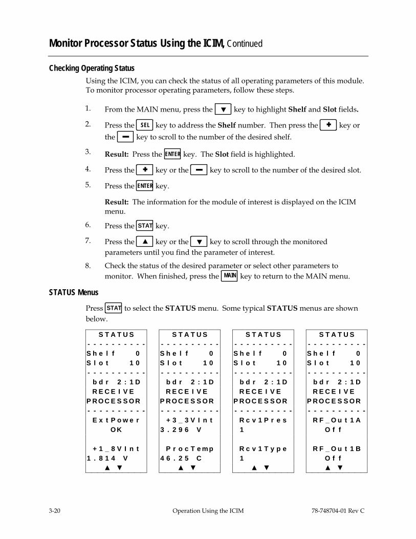
3-20 Operation Using the ICIM 78-748704-01 Rev C
Monitor Processor Status Using the ICIM, Continued
Checking Operating Status Using the ICIM, you can check the status of all operating parameters of this module. To monitor processor operating parameters, follow these steps.
1. From the MAIN menu, press the key to highlight Shelf and Slot fields.
2. Press the SEL key to address the Shelf number. Then press the key or the key to scroll to the number of the desired shelf.
3. Result: Press the ENTER key. The Slot field is highlighted.
4. Press the key or the key to scroll to the number of the desired slot.
5. Press the ENTER key.
Result: The information for the module of interest is displayed on the ICIM menu.
6. Press the STAT key.
7. Press the key or the key to scroll through the monitored parameters until you find the parameter of interest.
8. Check the status of the desired parameter or select other parameters to monitor. When finished, press the MAIN key to return to the MAIN menu.
STATUS Menus
Press STAT to select the STATUS menu. Some typical STATUS menus are shown below.
S T A T U S S T A T U S S T A T U S S T A T U S - - - - - - - - - - - - - - - - - - - - - - - - - - - - - - - - - - - - - - - - S h e l f 0 S h e l f 0 S h e l f 0 S h e l f 0 S l o t 1 0 S l o t 1 0 S l o t 1 0 S l o t 1 0 - - - - - - - - - - - - - - - - - - - - - - - - - - - - - - - - - - - - - - - - b d r 2 : 1 D b d r 2 : 1 D b d r 2 : 1 D b d r 2 : 1 D R E C E I V E R E C E I V E R E C E I V E R E C E I V E
P R O C E S S O R P R O C E S S O R P R O C E S S O R P R O C E S S O R - - - - - - - - - - - - - - - - - - - - - - - - - - - - - - - - - - - - - - - - E x t P o w e r + 3 _ 3 V I n t R c v 1 P r e s R F _ O u t 1 A O K 3 . 2 9 6 V 1 O f f + 1 _ 8 V I n t P r o c T e m p R c v 1 T y p e R F _ O u t 1 B
1 . 8 1 4 V 4 6 . 2 5 C 1 O f f ▲ ▼ ▲ ▼ ▲ ▼ ▲ ▼

78-748704-01 Rev C Operation Using the ICIM 3-21
Monitor Processor Status Using the ICIM, Continued
S T A T U S S T A T U S S T A T U S S T A T U S - - - - - - - - - - - - - - - - - - - - - - - - - - - - - - - - - - - - - - - - S h e l f 0 S h e l f 0 S h e l f 0 S h e l f 0 S l o t 1 0 S l o t 1 0 S l o t 1 0 S l o t 1 0 - - - - - - - - - - - - - - - - - - - - - - - - - - - - - - - - - - - - - - - - b d r 2 : 1 D b d r 2 : 1 D b d r 2 : 1 D b d r 2 : 1 D R E C E I V E R E C E I V E R E C E I V E R E C E I V E
P R O C E S S O R P R O C E S S O R P R O C E S S O R P R O C E S S O R - - - - - - - - - - - - - - - - - - - - - - - - - - - - - - - - - - - - - - - - R c v 2 P r e s R F _ O u t 2 A R e c v 1 R F O u t _ 1 A 1 O f f A c t i v e A u t o R c v 2 T y p e R F _ O u t 2 B R e d n R c v 1 R F O u t _ 1 B 1 O f f M a s t e r A u t o ▲ ▼ ▲ ▼ ▲ ▼ ▲ ▼ S T A T U S S T A T U S S T A T U S S T A T U S - - - - - - - - - - - - - - - - - - - - - - - - - - - - - - - - - - - - - - - - S h e l f 0 S h e l f 0 S h e l f 0 S h e l f 0 S l o t 1 0 S l o t 1 0 S l o t 1 0 S l o t 1 0 - - - - - - - - - - - - - - - - - - - - - - - - - - - - - - - - - - - - - - - - b d r 2 : 1 D b d r 2 : 1 D b d r 2 : 1 D b d r 2 : 1 D R E C E I V E R E C E I V E R E C E I V E R E C E I V E
P R O C E S S O R P R O C E S S O R P R O C E S S O R P R O C E S S O R - - - - - - - - - - - - - - - - - - - - - - - - - - - - - - - - - - - - - - - - R F A t t n 1 A R e c v 2 R F O u t _ 2 A R F A t t n 2 A
0 d B A c t i v e A u t o 0 d B R F A t t n 1 B R e d n R c v 2 R F O u t _ 2 B R F A t t n 2 B
0 d B M a s t e r A u t o 0 d B ▲ ▼ ▲ ▼ ▲ ▼

3-22 Operation Using the ICIM 78-748704-01 Rev C
Configure the Processor Using the ICIM
Introduction The ICIM allows you to configure parameters for the processor.
CONFIG Parameters The table below shows configurable parameters for the processor.
Parameter Functions Values Default
Recv1 Configures receiver 1 active or idle. Active or Idle Active
RednRcv1 Configures receiver 1 as Master (with or without a backup), Internal (backs-up the other receiver in the same processor), or External (backs-up another receiver in a separate processor). See note below.
Master, Internal, or External
Master
RFOut_1A RFOut_1B
Controls the muting of RF channels 1A and 1B. If Auto, the CCB determines if the output should be muted (only if in a redundancy mode). If On, the output is not muted. If Off, the output is muted.
Auto, On, Off Auto
RFAttn1A RFAttn1B
Attenuates the RF output channels 1A and 1B.
0 dB to 10 dB 0 dB
Recv2 Controls whether receiver 2 is active or idle.
Active or Idle Active
RednRcv2 Configures receiver 2 as Master (with or without backup), Internal (backs-up the other receiver in the same processor), or External (backs-up another receiver in a separate processor). See note below.
Master, Internal, or External
Master
RFOut_2A RFOut_2B
Controls the muting of RF channels 2A and 2B. If Auto, the CCB determines if the output should be muted (only if in a redundancy mode). If On, the output is not muted. If Off, the output is muted.
Auto, On, Off Auto
RFAttn2A RFAttn2B
Attenuates the RF output channels 2A and 2B.
0 dB to 10 dB 0 dB
Note: Both receivers in a single processor may also be set to Master with or without external redundancy. See Processor Configuration Options in Chapter 1.

78-748704-01 Rev C Operation Using the ICIM 3-23
Configure the Processor Using the ICIM, Continued
Configuring Parameters Using the ICIM, you can configure the parameters listed in the previous table.
Follow these steps to configure the parameters.
1. From the MAIN menu, press the key to highlight the Shelf and Slot fields.
2. Press the SEL key to address the Shelf number. Then press the key or the key to scroll to the number of the desired shelf.
3. Press the ENTER key.
Result: The Slot field is highlighted.
4. Press the key or the keys to scroll to the number of the desired slot.
5. Press the ENTER key.
Result: The initial information for the module of interest displays on the ICIM menu.
6. To configure the module, press the CFG key.
7. Press the key or the key to scroll through the configurable controls until you find the parameter of interest.
8. Press the SEL key to select the highlighted control.
9. Press the key or the key to activate or change the value of the selected control.
10. Press the ENTER key to save the changes and return to the MAIN menu.

3-24 Operation Using the ICIM 78-748704-01 Rev C
Configure the Processor Using the ICIM, Continued
CONFIG Menus Some typical processor CONFIG menus are shown below.
C O N F I G C O N F I G C O N F I G C O N F I G - - - - - - - - - - - - - - - - - - - - - - - - - - - - - - - - - - - - - - - - S h e l f 0 S h e l f 0 S h e l f 0 S h e l f 0 S l o t 1 0 S l o t 1 0 S l o t 1 0 S l o t 1 0 - - - - - - - - - - - - - - - - - - - - - - - - - - - - - - - - - - - - - - - - b d r 2 : 1 D b d r 2 : 1 D b d r 2 : 1 D b d r 2 : 1 D R E C E I V E R E C E I V E R E C E I V E R E C E I V E
P R O C E S S O R P R O C E S S O R P R O C E S S O R P R O C E S S O R - - - - - - - - - - - - - - - - - - - - - - - - - - - - - - - - - - - - - - - - R e c v 1 R F A t t n 1 B R F A t t n 2 A R e c v 1 R e d n R c v 1 R e c v 2 R F A t t n 2 B A c t i v e R F O u t _ 1 A R e d n R c v 2 R F O u t _ 1 B R F O u t _ 2 A R F A t t n 1 A R F O u t _ 2 B ▲ ▼ C O N F I G C O N F I G C O N F I G C O N F I G - - - - - - - - - - - - - - - - - - - - - - - - - - - - - - - - - - - - - - - - S h e l f 0 S h e l f 0 S h e l f 0 S h e l f 0 S l o t 1 0 S l o t 1 0 S l o t 1 0 S l o t 1 0 - - - - - - - - - - - - - - - - - - - - - - - - - - - - - - - - - - - - - - - - b d r 2 : 1 D b d r 2 : 1 D b d r 2 : 1 D b d r 2 : 1 D R E C E I V E R E C E I V E R E C E I V E R E C E I V E
P R O C E S S O R P R O C E S S O R P R O C E S S O R P R O C E S S O R - - - - - - - - - - - - - - - - - - - - - - - - - - - - - - - - - - - - - - - - R e d n R c v 1 R F O u t _ 1 A R F O u t _ 1 B R F A t t n 1 A M a s t e r A u t o A u t o 0 d B

78-748704-01 Rev C Operation Using the ICIM 3-25
Configure the Processor Using the ICIM, Continued
C O N F I G C O N F I G C O N F I G C O N F I G - - - - - - - - - - - - - - - - - - - - - - - - - - - - - - - - - - - - - - - - S h e l f 0 S h e l f 0 S h e l f 0 S h e l f 0 S l o t 1 0 S l o t 1 0 S l o t 1 0 S l o t 1 0 - - - - - - - - - - - - - - - - - - - - - - - - - - - - - - - - - - - - - - - - b d r 2 : 1 D b d r 2 : 1 D b d r 2 : 1 D b d r 2 : 1 D R E C E I V E R E C E I V E R E C E I V E R E C E I V E
P R O C E S S O R P R O C E S S O R P R O C E S S O R P R O C E S S O R - - - - - - - - - - - - - - - - - - - - - - - - - - - - - - - - - - - - - - - - R F A t t n 1 B R e c v 2 R e d n R c v 2 R F O u t _ 2 A
0 d B A c t i v e M a s t e r A u t o C O N F I G C O N F I G C O N F I G - - - - - - - - - - - - - - - - - - - - - - - - - - - - - - S h e l f 0 S h e l f 0 S h e l f 0 S l o t 1 0 S l o t 1 0 S l o t 1 0 - - - - - - - - - - - - - - - - - - - - - - - - - - - - - - b d r 2 : 1 D b d r 2 : 1 D b d r 2 : 1 D R E C E I V E R E C E I V E R E C E I V E
P R O C E S S O R P R O C E S S O R P R O C E S S O R - - - - - - - - - - - - - - - - - - - - - - - - - - - - - - R F O u t _ 2 B R F A t t n 2 A R F A t t n 2 B A u t o 0 d B 0 d B

3-26 Operation Using the ICIM 78-748704-01 Rev C
Check Processor Alarms Using the ICIM
Introduction The ICIM allows you to check processor alarms.
ALARMS Display The table below shows the alarm data available for the processor.
Alarm Alarm Condition Indication Possible Cause
DCPower Power supply indicates a fault
Fault Check power cord. Make sure power supply is fully seated.
ProcTemp Module Temperature Fault Check fan tray operation.
RdnInvld Redundant mode invalid
Invalid Both receivers are configured to Internal redundancy with no master.
Rcv1Inst Receiver 1 not present Fault Receiver 1 not present.
Rcv1Bias (APD Rx only)
APD 1 bias incorrect Fault Re-seat receiver 1. Replace if necessary.
Rcv1_LOS Receiver 1 loss of signal Fault Check fiber line and data into receiver 1.
Rcv1Data Receiver 1 no data Fault Check fiber line into receiver.
Rcv2Inst Receiver 1 not present Fault Receiver 2 not present.
Rcv2Bias (APD Rx only)
APD 2 bias incorrect Fault Re-seat receiver 2. Replace if necessary.
Rcv2_LOS Receiver 2 loss of signal Fault Check fiber line and data into receiver 2.
Rcv2Data Receiver 2 no data Fault Check fiber line into receiver.

78-748704-01 Rev C Operation Using the ICIM 3-27
Check Processor Alarms Using the ICIM, Continued
Checking Alarms If the red ALARM LED on the processor is blinking, a minor alarm condition is indicated. If the red ALARM LED on the front panel is illuminated, a critical alarm condition is indicated.
Alarms fall into one of the following categories. • Major low • Minor low • Minor high • Major high • Fault/OK
Follow these steps to check alarm conditions.
1. From the MAIN menu, press the key to highlight the Shelf and Slot fields.
2. Press the SEL key to address the Shelf number. Then press the key or the keys to scroll to the number of the desired shelf.
3. Press the ENTER key.
Result: The Slot field is highlighted.
4. Press the key or the key to scroll to the number of the desired slot.
5. Press the ENTER key.
Result: The MODULE menu is displayed on the ICIM.
6. Press the ALRM key.
Result: The module alarm conditions are displayed.
7. Use the key or the key to scroll through alarm conditions until the desired alarm is displayed.
8. Monitor the alarm condition(s) and take appropriate action. Verify that all settings and thresholds relating to the alarm indication are set correctly to rule out an unintended alarm.
9. When finished, press the MAIN key.
Result: The display returns to the MAIN menu.

3-28 Operation Using the ICIM 78-748704-01 Rev C
Check Processor Alarms Using the ICIM, Continued
Processor ALARMS Menus
When a module’s ALARMS menu is selected, press the key or the key to scroll through alarms. Some typical ALARMS menus are shown below.
A L A R M S A L A R M S A L A R M S A L A R M S - - - - - - - - - - - - - - - - - - - - - - - - - - - - - - - - - - - - - - - - S h e l f 0 S h e l f 0 S h e l f 0 S h e l f 0 S l o t 1 0 S l o t 1 0 S l o t 1 0 S l o t 1 0 - - - - - - - - - - - - - - - - - - - - - - - - - - - - - - - - - - - - - - - - b d r 2 : 1 D b d r 2 : 1 D b d r 2 : 1 D b d r 2 : 1 D R E C E I V E R E C E I V E R E C E I V E R E C E I V E
P R O C E S S O R P R O C E S S O R P R O C E S S O R P R O C E S S O R - - - - - - - - - - - - - - - - - - - - - - - - - - - - - - - - - - - - - - - - D C P o w e r P r o c T e m p R d n I n v l d R c v 1 I n s t F a u l t F a u l t F a u l t F a u l t ▲ ▼ ▲ ▼ ▲ ▼ A L A R M S A L A R M S A L A R M S A L A R M S - - - - - - - - - - - - - - - - - - - - - - - - - - - - - - - - - - - - - - - - S h e l f 0 S h e l f 0 S h e l f 0 S h e l f 0 S l o t 1 0 S l o t 1 0 S l o t 1 0 S l o t 1 0 - - - - - - - - - - - - - - - - - - - - - - - - - - - - - - - - - - - - - - - - b d r 2 : 1 D b d r 2 : 1 D b d r 2 : 1 D b d r 2 : 1 D R E C E I V E R E C E I V E R E C E I V E R E C E I V E
P R O C E S S O R P R O C E S S O R P R O C E S S O R P R O C E S S O R - - - - - - - - - - - - - - - - - - - - - - - - - - - - - - - - - - - - - - - - R c v 1 B i a s R c v 1 _ L O S R c v 1 D a t a R c v 2 I n s t F a u l t F a u l t F a u l t F a u l t ▲ ▼ ▲ ▼ ▲ ▼ ▲ ▼

78-748704-01 Rev C Operation Using the ICIM 3-29
Check Processor Alarms Using the ICIM, Continued
A L A R M S A L A R M S A L A R M S - - - - - - - - - - - - - - - - - - - - - - - - - - - - - - S h e l f 0 S h e l f 0 S h e l f 0 S l o t 1 0 S l o t 1 0 S l o t 1 0 - - - - - - - - - - - - - - - - - - - - - - - - - - - - - - b d r 2 : 1 D b d r 2 : 1 D b d r 2 : 1 D R E C E I V E R E C E I V E R E C E I V E
P R O C E S S O R P R O C E S S O R P R O C E S S O R - - - - - - - - - - - - - - - - - - - - - - - - - - - - - - R c v 2 B i a s R c v 2 _ L O S R c v 2 D a t a F a u l t F a u l t F a u l t ▲ ▼ ▲ ▼ ▲ ▼

3-30 Operation Using the ICIM 78-748704-01 Rev C
Check Manufacturing Data Using the ICIM
Introduction The ICIM allows you to check manufacturing data.
Checking Manufacturing Data Follow these steps to access the processor’s manufacturing data.
1. From the MAIN menu, press the key to highlight the Shelf and Slot fields.
2. Press the SEL key to address the Shelf number. Then press the key or the keys to scroll to the number of the desired shelf.
3. Press the ENTER key.
Result: The Slot field is highlighted.
4. Press the key or the key to scroll to the number of the desired slot.
5. Press the ENTER key. The MODULE menu for this module will be selected, as shown on the left below. Press the key to enter the start of the manufacturing data screens, as shown on the right menu below. M O D U L E M F G . D A T A - - - - - - - - - - - - - - - - - - - - S h e l f 0 S h e l f 0 S l o t 8 S l o t 8 - - - - - - - - - - - - - - - - - - - - b d r 2 : 1 D b d r 2 : 1 D R E C E I V E R E C E I V E
P R O C E S S O R P R O C E S S O R - - - - - - - - - - - - - - - - - - - - A l a r m s M o d u l e 1 T y p e - - - - - - - - - - M f g . D a t a 2 0 0 7 ▲ ▼ ▲ ▼
6. The or keys allow you to scroll through the manufacturing data.

78-748704-01 Rev C Operation Using the ICIM 3-31
Check Manufacturing Data Using the ICIM, Continued
Manufacturing Data Display The table below describes the manufacturing data available for this module.
Manufacturing Data Explanation
Module Type Cisco module type number
Serial # The alphanumeric device serial number
Date Code Code describing year and month of module manufacture
Sw Ver (Software Version) Core code software version
Script Ver (Script Version) Module software script version
In Service Hours Number of hours that the module has been used
Spec Data No special data for this module
Restore Factory Defaults Restores all factory default configuration settings

3-32 Operation Using the ICIM 78-748704-01 Rev C
Check Manufacturing Data Using the ICIM, Continued
MFG. DATA Screens
When the MFG. DATA screen is selected, the key or the key allows you to scroll through the manufacturing parameters specific to this module. Some typical MFG. DATA screens are shown below.
M F G . D A T A M F G . D A T A M F G . D A T A M F G . D A T A - - - - - - - - - - - - - - - - - - - - - - - - - - - - - - - - - - - - - - - - S h e l f 0 S h e l f 0 S h e l f 0 S h e l f 0 S l o t 1 0 S l o t 1 0 S l o t 1 0 S l o t 1 0 - - - - - - - - - - - - - - - - - - - - - - - - - - - - - - - - - - - - - - - - b d r 2 : 1 D b d r 2 : 1 D b d r 2 : 1 D b d r 2 : 1 D R E C E I V E R E C E I V E R E C E I V E R E C E I V E
P R O C E S S O R P R O C E S S O R P R O C E S S O R P R O C E S S O R - - - - - - - - - - - - - - - - - - - - - - - - - - - - - - - - - - - - - - - - M o d u l e S e r i a l # S W V e r T y p e ! A A Y C U A Z N C C B 1 0 0 I n S e r v i c e D a t e C o d e S c r i p t V e r H o u r s 2 0 0 7 F 0 0 2 1 0 ▲ ▼ ▲ ▼ ▲ ▼ ▲ ▼ M F G . D A T A M F G . D A T A - - - - - - - - - - - - - - - - - - - - S h e l f 0 S h e l f 0 S l o t 1 0 S l o t 1 0 - - - - - - - - - - - - - - - - - - - - b d r 2 : 1 D b d r 2 : 1 D R E C E I V E R E C E I V E
P R O C E S S O R P R O C E S S O R - - - - - - - - - - - - - - - - - - - - S p e c D a t a R e s t o r e F a c t o r y P r i s m a I I D e f a u l t s ▲ ▼

78-748704-01 Rev C Operation Using the ICIM 3-33
Save the Configuration Using the ICIM
Introduction The following instructions explain how to save your processor’s configuration using ICIM.
Saving the Current Configuration Follow these steps after every change to save the current module configuration.
1. After you have changed a parameter or entered data, press the ENTER key to save the changes and return to the MAIN menu.
2. If you do not save your changes for two minutes, or if you press the SHIFT CAN keys at the same time, changes are aborted and the display returns to
the MAIN menu.
Configuration Complete Once you have configured this module to your system’s specifications using the ICIM and no alarms are indicated, no further action is necessary. The module operates without further input. Alarms, changes in operating parameters, electrical power fluctuations, or changes in system design may be cause for additional action.
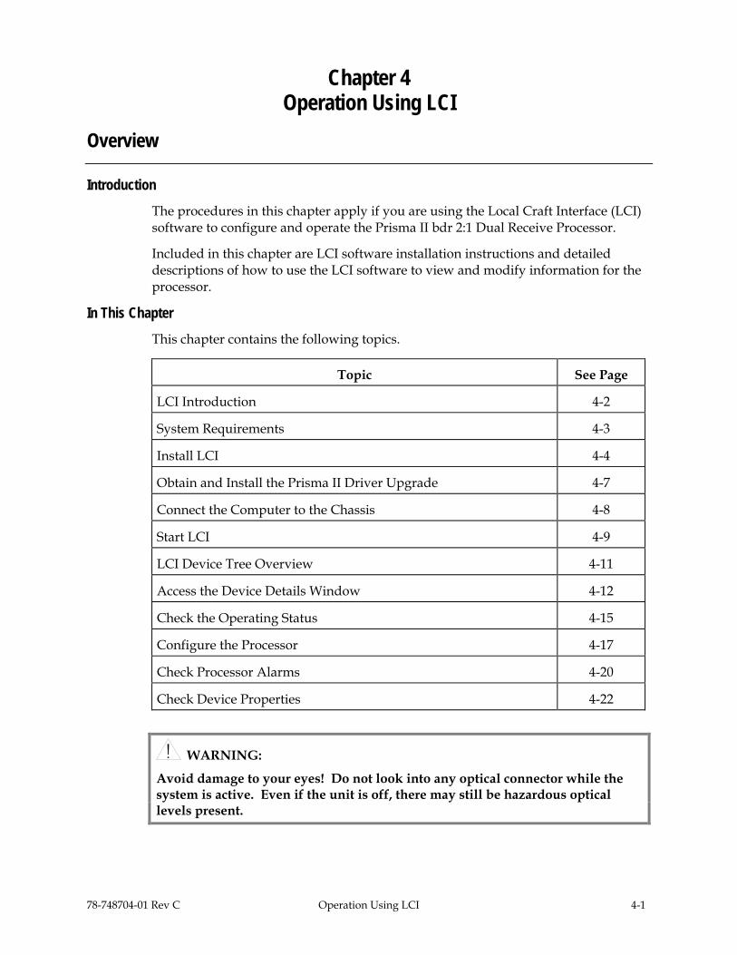
78-748704-01 Rev C Operation Using LCI 4-1
Chapter 4 Operation Using LCI
Overview
Introduction The procedures in this chapter apply if you are using the Local Craft Interface (LCI) software to configure and operate the Prisma II bdr 2:1 Dual Receive Processor.
Included in this chapter are LCI software installation instructions and detailed descriptions of how to use the LCI software to view and modify information for the processor.
In This Chapter This chapter contains the following topics.
Topic See Page
LCI Introduction 4-2
System Requirements 4-3
Install LCI 4-4
Obtain and Install the Prisma II Driver Upgrade 4-7
Connect the Computer to the Chassis 4-8
Start LCI 4-9
LCI Device Tree Overview 4-11
Access the Device Details Window 4-12
Check the Operating Status 4-15
Configure the Processor 4-17
Check Processor Alarms 4-20
Check Device Properties 4-22
WARNING:
Avoid damage to your eyes! Do not look into any optical connector while the system is active. Even if the unit is off, there may still be hazardous optical levels present.

4-2 Operation Using LCI 78-748704-01 Rev C
LCI Introduction
The LCI Software Function The LCI software functions as a user interface for the Prisma II platform. The LCI software is installed on a PC, which is then connected to a Prisma II Chassis. Using the LCI software, you can configure and monitor the modules in the chassis the computer is connected to.
Important: Do not operate any Prisma II Chassis without a fan tray installed. If a fan tray is not installed in the chassis, the LCI software will not communicate with the power supplies in that chassis.
78-748704-01 Rev C Operation Using LCI 4-3
System Requirements
Introduction You will need the following computer software and hardware to run the LCI software. Typically, a laptop PC is used for portability.
Computer Requirements • Pentium II 300 MHz processor or equivalent • 128 MB RAM • 10 MB available hard drive space • 1.44 MB floppy drive • CD-ROM Drive • Windows 98 or later operating system software
Cabling Requirements The cable required for connecting a PC to a chassis is a standard “off the shelf” DB-9 female to DB-9 male serial extension cable. The connectors are a serial 9-pin D-shell (EIA 574/232).
The Cisco part number for a six-foot DB-9 female to DB-9 male extension cable is 180143.
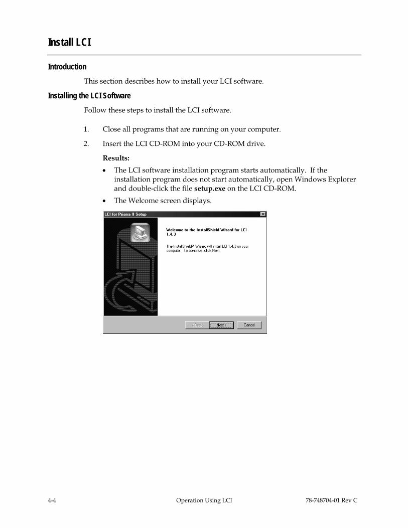
4-4 Operation Using LCI 78-748704-01 Rev C
Install LCI
Introduction This section describes how to install your LCI software.
Installing the LCI Software Follow these steps to install the LCI software.
1. Close all programs that are running on your computer.
2. Insert the LCI CD-ROM into your CD-ROM drive.
Results: • The LCI software installation program starts automatically. If the
installation program does not start automatically, open Windows Explorer and double-click the file setup.exe on the LCI CD-ROM.
• The Welcome screen displays.

78-748704-01 Rev C Operation Using LCI 4-5
Install LCI, Continued
3. Click Next.
Result: The License Agreement screen displays.
4. Click Yes to accept the license agreement.
Result: The License Agreement dialog box displays.
5. Click Yes.
Result: The Destination Folder window displays.

4-6 Operation Using LCI 78-748704-01 Rev C
Install LCI, Continued
6. Do you want to install the LCI software in the folder displayed in the Folder box? • If yes, click Next to begin the installation, and proceed to step 9. • If no, proceed to step 7.
7. To specify where you want the LCI software to be installed, type the path in the Folder box.
8. Click Next to begin the installation.
Result: The last installation wizard window displays after the installation is complete.
9. Before you can use the LCI software, you must restart your computer. Choose whether to restart your computer now or later by selecting the appropriate option button.
10. Click Finish. After your computer is restarted, you can use the LCI software.

78-748704-01 Rev C Operation Using LCI 4-7
Obtain and Install the Prisma II Driver Upgrade
Introduction A Prisma II driver upgrade is needed to operate the processor using LCI software version 1.4.3.
Important: This upgrade is not required to operate the processor if you are using an ICIM or any LCI software later than 1.4.3.
Required Software To operate the processor using LCI, you must have (in addition to Windows) the following Cisco software installed on your PC. • LCI software, version 1.4.3 or later • Prisma II driver upgrade (if using LCI version 1.4.3)
Important: If you are using LCI software version 1.4.3, it must be installed on your PC prior to installing the driver upgrade. LCI software version 1.4.3 was shipped on CD-ROM with the 56-connector chassis and is also available on the Web: http://www.scientificatlanta.com/tncs/upgrades/upgrades.htm.
Obtaining the Driver Upgrade Internet access is required in order to obtain this software. To obtain the driver upgrade, you must download it from:
http://www.scientificatlanta.com/tncs/upgrades/upgrades.htm
Downloads may be made to any computer but must ultimately be installed on the PC running the LCI software.
Downloading and Installing the Driver Upgrade (LCI Software Version 1.4.3 ONLY) Follow these steps to install the upgrade.
1. Ensure that LCI software version 1.4.3 is installed on your system. If it is not, refer to Install LCI earlier in this chapter for instructions.
2. Access the Web site shown above.
3. Click the Prisma II Driver Upgrade link.
4. At the prompt, save the file to a location of your choice on your system.
5. In Windows Explorer, double-click the saved file.
6. Follow the prompts of the installation program. The driver upgrade is installed in the proper location on your system. The LCI software is now ready to use with the processor.

4-8 Operation Using LCI 78-748704-01 Rev C
Connect the Computer to the Chassis
Introduction Before you start the LCI software, you must first connect your computer to the chassis that contains the module(s) you want to check.
Important: The LCI software communicates only with those modules located in the chassis your computer is attached to. To check other modules, you must connect your computer to the chassis where the modules reside.
Connecting to the Chassis Follow these steps to connect your PC to the chassis.
1. Plug the female end of a 9-pin serial extension cable into your computer.
2. Plug the male end of the cable into the Local Craft Interface port.

78-748704-01 Rev C Operation Using LCI 4-9
Start LCI
Introduction When you start the LCI software, it queries the devices (modules) located in the chassis that is connected to your computer. After this query process (referred to as the learn mode), the LCI software does the following for each device it finds. • Represents the device in the device tree of the main LCI window • Makes the polling information available so you can check and configure various
parameters
Important: Your computer must be connected to the chassis before you start the LCI software. For instructions, refer to Connect the Computer to the Chassis earlier in this chapter.
Starting the LCI Software Follow these steps to start the software.
1. Double-click the LCI icon on your Windows desktop.
Result: The LCI Main window opens and the LCI Detect Configuration dialog box displays.
2. Verify the communication port displayed in the COM Port box. This is the port on your computer that the chassis is connected to.
To change the COM port, type the word “COM” and then the port number.
Example: To specify COM port 2, type COM2.
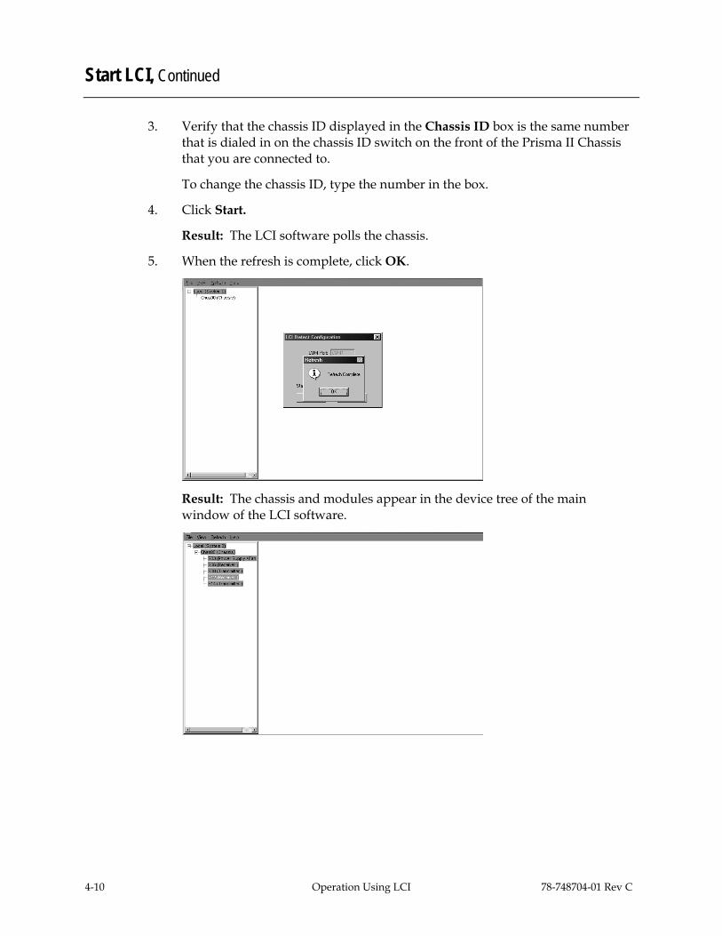
4-10 Operation Using LCI 78-748704-01 Rev C
Start LCI, Continued
3. Verify that the chassis ID displayed in the Chassis ID box is the same number that is dialed in on the chassis ID switch on the front of the Prisma II Chassis that you are connected to.
To change the chassis ID, type the number in the box.
4. Click Start.
Result: The LCI software polls the chassis.
5. When the refresh is complete, click OK.
Result: The chassis and modules appear in the device tree of the main window of the LCI software.

78-748704-01 Rev C Operation Using LCI 4-11
LCI Device Tree Overview
Introduction The main window of the LCI software contains a tree that represents your system in a hierarchical manner.
Device Tree In the graphic above, the device tree represents a PC connected to a chassis that contains five modules. The three tree levels are described in the following table.
Device Tree Level Description
Local (System 0) PC being used
Chass00 (Chassis) Chassis the computer is connected to
Sxx (Device name) Module(s) located within the chassis. Each device is of the format chassis slot location (device name).
Example: In the graphic above, S10 (Receiver) represents a bdr 2:1 Dual Receive Processor that is located in slot 10 of the chassis.

4-12 Operation Using LCI 78-748704-01 Rev C
Access the Device Details Window
Introduction Information about a device (its parameters, alarms, and status) is located in the Device Details window. The graphic below shows the Device Details window for a Prisma II bdr Dual Receive Processor.
Within the LCI device tree, you can access this window using one of the following four methods: • Double-click the chassis and select the device in the graphic that displays • Right-click the chassis and select Open from the menu that displays • Double-click the module • Right-click the device and select Details from the menu that displays
Note: Although you can use the method that is most convenient for you, the procedures throughout this chapter are described using the right-click device technique.
For more information about the device tree, refer to LCI Device Tree Overview earlier in this chapter.

78-748704-01 Rev C Operation Using LCI 4-13
Access the Device Details Window, Continued
Right-Click the Chassis Follow these steps to access the Device Details window.
1. Right-click the chassis, and click Open.
Result: A graphic representation of the chassis displays.

4-14 Operation Using LCI 78-748704-01 Rev C
Access the Device Details Window, Continued
2. Double-click the device whose information you want to view and/or configure.
Result: The Device Details window displays.
3. Proceed with viewing and/or configuring information.
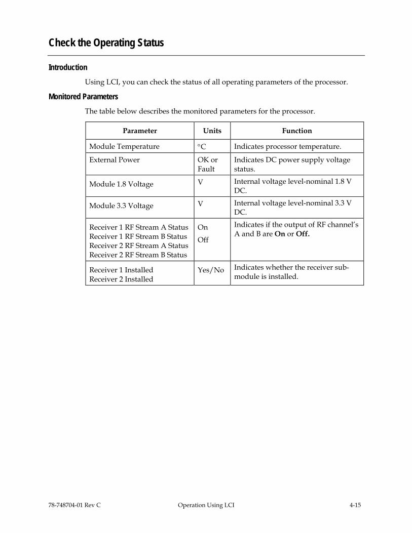
78-748704-01 Rev C Operation Using LCI 4-15
Check the Operating Status
Introduction Using LCI, you can check the status of all operating parameters of the processor.
Monitored Parameters The table below describes the monitored parameters for the processor.
Parameter Units Function
Module Temperature °C Indicates processor temperature.
External Power OK or Fault
Indicates DC power supply voltage status.
Module 1.8 Voltage V Internal voltage level-nominal 1.8 V DC.
Module 3.3 Voltage V Internal voltage level-nominal 3.3 V DC.
Receiver 1 RF Stream A Status Receiver 1 RF Stream B Status Receiver 2 RF Stream A Status Receiver 2 RF Stream B Status
On
Off
Indicates if the output of RF channel’s A and B are On or Off.
Receiver 1 Installed Receiver 2 Installed
Yes/No Indicates whether the receiver sub-module is installed.

4-16 Operation Using LCI 78-748704-01 Rev C
Check the Operating Status, Continued
Checking the Operating Status To monitor the processor operating parameters, follow these steps.
1. Access the Device Details window. The monitored parameters are displayed under Parameters and Status.
2. Proceed with checking the operating parameters.
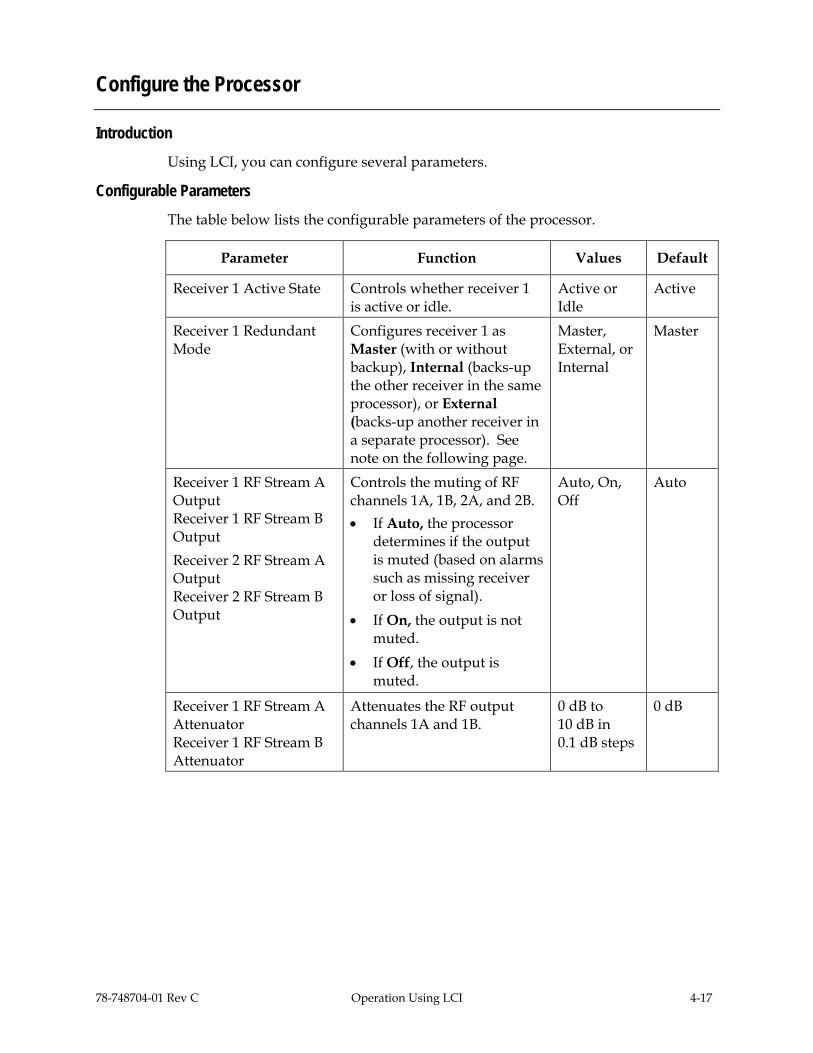
78-748704-01 Rev C Operation Using LCI 4-17
Configure the Processor
Introduction Using LCI, you can configure several parameters.
Configurable Parameters The table below lists the configurable parameters of the processor.
Parameter Function Values Default
Receiver 1 Active State Controls whether receiver 1 is active or idle.
Active or Idle
Active
Receiver 1 Redundant Mode
Configures receiver 1 as Master (with or without backup), Internal (backs-up the other receiver in the same processor), or External (backs-up another receiver in a separate processor). See note on the following page.
Master, External, or Internal
Master
Receiver 1 RF Stream A Output Receiver 1 RF Stream B Output Receiver 2 RF Stream A Output Receiver 2 RF Stream B Output
Controls the muting of RF channels 1A, 1B, 2A, and 2B. • If Auto, the processor
determines if the output is muted (based on alarms such as missing receiver or loss of signal).
• If On, the output is not muted.
• If Off, the output is muted.
Auto, On, Off
Auto
Receiver 1 RF Stream A Attenuator Receiver 1 RF Stream B Attenuator
Attenuates the RF output channels 1A and 1B.
0 dB to 10 dB in 0.1 dB steps
0 dB

4-18 Operation Using LCI 78-748704-01 Rev C
Configure the Processor, Continued
Parameter Function Values Default
Receiver 2 Active State Controls whether receiver 2 is active or idle.
Active or Idle
Active
Receiver 2 Redundant Mode
Configures receiver 2 as Master (with or without backup), Internal (backs-up the other receiver in the same processor), or External (backs-up another receiver in a separate processor). Seen note below.
Master, External, or Internal
Master
Receiver 2 RF Stream A Attenuator Receiver 2 RF Stream B Attenuator
Attenuates the RF output channels 2A and 2B.
0 dB to 10 dB in 0.1 dB steps
0 dB
Note: Both receivers in a single processor may also be set to Master with or without external redundancy. See Processor Configuration Options in Chapter 1.

78-748704-01 Rev C Operation Using LCI 4-19
Configure the Processor, Continued
Configuring Parameters Follow these steps to configure the parameters.
1. Access the Device Details window.
2. Under Controls, double-click the parameter you want to configure.
Result: The Change Value dialog box opens. The graphic below shows the dialog box for the Receiver 1 Active State parameter of the processor.
3. Depending on the parameter you chose, select or type a new value.
4. Click Execute.
Result: The new value displays next to the parameter.

4-20 Operation Using LCI 78-748704-01 Rev C
Check Processor Alarms
Introduction Using LCI, you can check the alarm status of various parameters. Alarms that you can check are listed below.
Alarm Alarm Condition Indication Possible Cause
Summary Status Normal or Alarm Alarm Any alarm in the device.
External Power Status
Power supply indicates a fault
Alarm Check power cord. Make sure power supply is fully seated.
Redundant Mode Status
Indicates Invalid if both receivers are configured to Internal redundancy with no master.
Invalid Valid=No more than one receiver is configured to Internal redundancy. Invalid=Both receivers are configured to Internal redundancy with no master.
Framing Status The signal cannot be framed
Alarm Check fiber connection path and bdr transmitter.
Receiver 1 Status Receiver 1 not present
Alarm Receiver 1 not present.
Receiver Clock 1 Status
Receiver 1 clock operation
Alarm Hardware failure. Unit needs repair.
Receiver 1 Data Status
Receiver 1 data not received
Alarm Check rear line and data into receiver.
Receiver 2 Status Receiver 2 not present
Alarm Receiver 2 not present.
Receiver Clock 2 Status
Receiver 2 clock operation
Alarm Hardware failure. Unit needs repair.
Receiver 2 Data Status
Receiver 2 data not received
Alarm Check rear line and data into receiver.
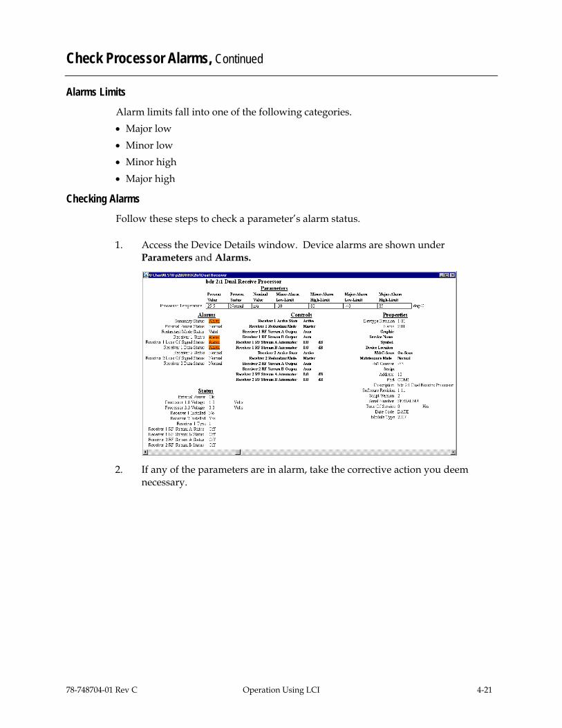
78-748704-01 Rev C Operation Using LCI 4-21
Check Processor Alarms, Continued
Alarms Limits Alarm limits fall into one of the following categories. • Major low • Minor low • Minor high • Major high
Checking Alarms Follow these steps to check a parameter’s alarm status.
1. Access the Device Details window. Device alarms are shown under Parameters and Alarms.
2. If any of the parameters are in alarm, take the corrective action you deem necessary.

4-22 Operation Using LCI 78-748704-01 Rev C
Check Device Properties
Introduction Using the LCI software, you can check the device properties of the processor.
Device Properties The table below describes the device properties available for the processor.
Properties Explanation
Description Description of the device
Software Revision Core code software revision
Script Version Module software script version
Serial number The alphanumeric device serial number
Time of Service Number of hours that the device has been used
Day Code Code describing year and month of manufacture
Device Type Cisco device type number

78-748704-01 Rev C Operation Using LCI 4-23
Check Device Properties, Continued
Checking Device Properties Follow these steps to access the Device Properties,
1. Access the Device Details window. The device properties are displayed under Properties.
2. Proceed with viewing the device properties.

78-748704-01 Rev C Maintenance and Troubleshooting 5-1
Chapter 5 Maintenance and Troubleshooting
Overview
Introduction This chapter provides information to assist you in maintaining and troubleshooting the Prisma II bdr 2:1 Dual Receive Processor.
Qualified Personnel Only appropriately qualified and trained personnel should attempt to troubleshoot this product.
WARNING:
Allow only qualified personnel to install, operate, maintain, or service this product. Otherwise, personal injury or equipment damage may occur.
In This Chapter This chapter contains the following topics.
Topic See Page
Module Maintenance 5-2
General Troubleshooting Information 5-3
Troubleshoot Alarm Conditions 5-4
Troubleshoot LCI 5-5
Clean Fiber-Optic Connectors 5-12

5-2 Maintenance and Troubleshooting 78-748704-01 Rev C
Module Maintenance
Introduction Regular maintenance is required to extend the life of the module and ensure optimal performance.
Required Maintenance The following table describes the recommended maintenance.
Frequency Maintenance Required
Weekly • Check all parameters and test points • Record data • Make repairs and adjustments as needed
Quarterly • Make sure all cables are mated properly • Inspect cables for stress and chafing • Make sure all retaining screws are tight
When needed Carefully clean the module with a soft cloth that is dampened with mild detergent

78-748704-01 Rev C Maintenance and Troubleshooting 5-3
General Troubleshooting Information
Introduction This troubleshooting information describes the most common alarms and gives typical symptoms, causes, and items to check before consulting us.
Equipment Needed You may need the following equipment to troubleshoot the chassis. • Digital voltmeter • Fiber connector cleaning materials
Additional Assistance If you need additional assistance, telephone one of our Technical Service Centers or your local sales subsidiary. The Customer Support section in Chapter 6, Customer Information contains a list of telephone numbers.
Troubleshooting
WARNING:
Avoid electric shock and damage to this product! Do not open the enclosure of this product. There are no user-serviceable parts inside. Refer servicing to qualified service personnel.
Refer to the following section, Troubleshoot Alarm Conditions, to identify and correct module faults.

5-4 Maintenance and Troubleshooting 78-748704-01 Rev C
Troubleshoot Alarm Conditions
Introduction
If the red ALARM indicator is illuminated or blinking, check the ICIM to determine the cause of the alarm. Blinking = minor alarm, steady illumination = major alarm.
ICIM Alarm Conditions The table below shows the alarm conditions and possible causes.
Alarm Alarm Condition Indication Possible Cause
DCPower Power supply indicates a fault
Fault Check power cord. Make sure power supply is fully seated.
ProcTemp Module Temperature Fault Check fan tray operation.
RdnInvld Redundant mode invalid
Invalid Both receivers are configured to Internal redundancy with no master.
Rcv1Inst Receiver 1 not present Fault Receiver 1 not present.
Rcv1Bias (APD Rx only)
APD 1 bias incorrect Fault Re-seat receiver 1. Replace if necessary.
Rcv1_LOS Receiver 1 loss of signal Fault Check fiber line and data into receiver 1.
Rcv1Data Receiver 1 no data Fault Check fiber line into receiver.
Rcv2Inst Receiver 1 not present Fault Receiver 2 not present.
Rcv2Bias (APD Rx only)
APD 2 bias incorrect Fault Re-seat receiver 2. Replace if necessary.
Rcv2_LOS Receiver 2 loss of signal Fault Check fiber line and data into receiver 2.
Rcv2Data Receiver 2 no data Fault Check fiber line into receiver.
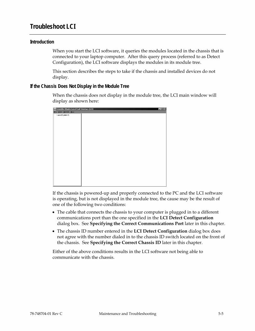
78-748704-01 Rev C Maintenance and Troubleshooting 5-5
Troubleshoot LCI
Introduction When you start the LCI software, it queries the modules located in the chassis that is connected to your laptop computer. After this query process (referred to as Detect Configuration), the LCI software displays the modules in its module tree.
This section describes the steps to take if the chassis and installed devices do not display.
If the Chassis Does Not Display in the Module Tree When the chassis does not display in the module tree, the LCI main window will display as shown here:
If the chassis is powered-up and properly connected to the PC and the LCI software is operating, but is not displayed in the module tree, the cause may be the result of one of the following two conditions: • The cable that connects the chassis to your computer is plugged in to a different
communications port than the one specified in the LCI Detect Configuration dialog box. See Specifying the Correct Communications Port later in this chapter.
• The chassis ID number entered in the LCI Detect Configuration dialog box does not agree with the number dialed in to the chassis ID switch located on the front of the chassis. See Specifying the Correct Chassis ID later in this chapter.
Either of the above conditions results in the LCI software not being able to communicate with the chassis.

5-6 Maintenance and Troubleshooting 78-748704-01 Rev C
Troubleshoot LCI, Continued
Specifying the Correct Communications Port
Follow these steps to specify the correct communications port.
1. In the module tree, right-click Local (System 0). Click Open on menu that displays.
Result: The LCI Server Object window displays.
2. Verify that the Communications Port setting is the port on the PC actually used to connect to the chassis. • If the correct port is shown, proceed to Specifying the Correct Chassis ID. • If the correct port is not shown, proceed to step 3.
3. Under Interface, double-click Communications Port. In the Command to box, type the number of the COM port actually in use connecting the PC to the chassis.
Example: To specify COM port 1, type COM1.

78-748704-01 Rev C Maintenance and Troubleshooting 5-7
Troubleshoot LCI, Continued
4. Click Execute.
Result: The Communication Port field displays the correct COM port.
5. Click Refresh.
Result: The LCI Detect Configuration dialog box displays.

5-8 Maintenance and Troubleshooting 78-748704-01 Rev C
Troubleshoot LCI, Continued
6. Click Start.
Result: The Refresh window displays when the chassis polling is complete.
7. Click OK, and then return to the main window.
8. The chassis should now display in the module tree as shown below. If not, proceed to Specifying the Correct Chassis ID.

78-748704-01 Rev C Maintenance and Troubleshooting 5-9
Troubleshoot LCI, Continued
Specifying the Correct Chassis ID
If the chassis ID in the Chassis ID field of the Local Server Object window does not agree with the number set in the chassis ID switch on the front of the chassis, the software will not recognize the chassis.
In this case, you must change the chassis ID displayed in the Local Server Object window for LCI to recognize the chassis.
Follow these steps to specify the correct chassis ID.
1. In the module tree, right-click Local (System 0). Click Open on the menu that displays.
Result: The LCI Server Object window displays.

5-10 Maintenance and Troubleshooting 78-748704-01 Rev C
Troubleshoot LCI, Continued
2. Verify that the Chassis ID field matches the number on the chassis ID switch on the front of the chassis. • If the chassis IDs do not match, double-click the Chassis ID field, enter the
number that is dialed in on the chassis ID switch, and click Execute. • If the chassis IDs match, re-initiate power to the chassis by doing one of
the following: − If the chassis ID switch was changed after the chassis was powered up,
you will need to power-down, then power-up the chassis. − If an ICIM is installed in the chassis, you can implement the Update
Address command using the ICIM key. This allows the modules to identify their correct location to the LCI software and the ICIM.
Only Some of the Modules Display in the Module Tree If only some of your modules display in the module tree, the cause may be that a device has been added since the software last polled the chassis.
Follow these steps to refresh the display.
1. Click Refresh.
Result: The LCI Detect Configuration dialog box displays.
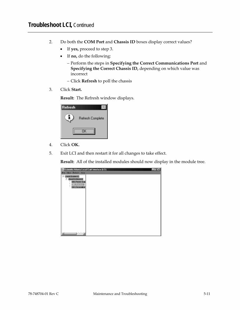
78-748704-01 Rev C Maintenance and Troubleshooting 5-11
Troubleshoot LCI, Continued
2. Do both the COM Port and Chassis ID boxes display correct values? • If yes, proceed to step 3. • If no, do the following:
− Perform the steps in Specifying the Correct Communications Port and Specifying the Correct Chassis ID, depending on which value was incorrect
− Click Refresh to poll the chassis
3. Click Start.
Result: The Refresh window displays.
4. Click OK.
5. Exit LCI and then restart it for all changes to take effect.
Result: All of the installed modules should now display in the module tree.

5-12 Maintenance and Troubleshooting 78-748704-01 Rev C
Clean Fiber-Optic Connectors
Introduction Clean fiber-optic connectors can help prevent interconnect problems and therefore aid system performance. When optical connectors are disconnected and reconnected, the fiber surface can become dirty or scratched. The goal of cleaning the fiber-optic connectors is to remove all dust and contaminants without leaving any residue behind.
Required Equipment The following equipment is required to clean the ends of fiber-optic connectors. • Optical-grade (91%) isopropyl alcohol • Lint-free wipes • Compressed air (also called “canned air”)
Tips for Optimal Fiber-Optic Connector Performance Follow these guidelines to ensure optimal connector performance. • Connect or disconnect optical connectors only when necessary. • Always use compressed air before cleaning the fiber-optic connectors. • Use end caps on connectors when they are not in use. • Always use compressed air to clean the end caps. • Use optical-grade isopropyl alcohol of at least 91% or greater. Anything less than
91% isopropyl may leave a film on the fiber surface, creating more problems. • Do not contaminate your alcohol supply. − Use a sprayer (a fountain pump is also adequate) − Do not put used alcohol back into the main container
• Use only lint-free wipes. Never use “Kleenex-type” tissues. • If you have any degraded signal problems, clean the fiber-optic connector.

78-748704-01 Rev C Maintenance and Troubleshooting 5-13
Clean Fiber-Optic Connectors, Continued
Cleaning Optical Connectors Follow these steps to clean an optical connector.
1. Remove loose dirt or dust from the end of the connector by using compressed air to blow dirt off the fiber and the connector.
2. Dampen a lint-free wipe with optical-grade (91%) isopropyl alcohol. If no wipes are available, use Cisco’s ferrule cleaner, part number 468517.
3. Wipe the end of the connector with the lint-free wipe.
4. Inspect the end of the connector for obvious contamination.
5. Mate the connector with an adapter or cover with an end cap.

78-748704-01 Rev C Customer Information 6-1
Chapter 6 Customer Information
Overview
If You Have Questions If you have technical questions, call Cisco Services for assistance. Follow the menu options to speak with a service engineer. Access your company's extranet site to view or order additional technical publications. For accessing instructions, contact the representative who handles your account. Check your extranet site often as the information is updated frequently.
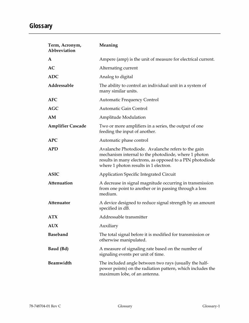
78-748704-01 Rev C Glossary Glossary-1
Glossary
Term, Acronym, Abbreviation
Meaning
A Ampere (amp) is the unit of measure for electrical current.
AC Alternating current
ADC Analog to digital
Addressable The ability to control an individual unit in a system of many similar units.
AFC Automatic Frequency Control
AGC Automatic Gain Control
AM Amplitude Modulation
Amplifier Cascade Two or more amplifiers in a series, the output of one feeding the input of another.
APC Automatic phase control
APD Avalanche Photodiode. Avalanche refers to the gain mechanism internal to the photodiode, where 1 photon results in many electrons, as opposed to a PIN photodiode where 1 photon results in 1 electron.
ASIC Application Specific Integrated Circuit
Attenuation A decrease in signal magnitude occurring in transmission from one point to another or in passing through a loss medium.
Attenuator A device designed to reduce signal strength by an amount specified in dB.
ATX Addressable transmitter
AUX Auxiliary
Baseband The total signal before it is modified for transmission or otherwise manipulated.
Baud (Bd) A measure of signaling rate based on the number of signaling events per unit of time.
Beamwidth The included angle between two rays (usually the half-power points) on the radiation pattern, which includes the maximum lobe, of an antenna.

Glossary-2 Glossary 78-748704-01 Rev C
Glossary, Continued
BER Bit error rate
BERT Bit error rate test
BIG Broadband Integrated Gateway
BIOS Basic Input/Output System
BIST Built-in self-test
Bit Short for Binary Digit. Can be either a "one" or a "zero."
Blanking level The amplitude of the front and back porches of the composite video signal.
BNC A coaxial connector that uses a bayonet type attachment to secure the cable. It is also known as Baby N connector.
BPF Bandpass filter
Bps Bits per second - The total number of bits sent in a second of time.
BPSK Binary Phase Shift Keying
BW Bandwidth
Byte A group of bits treated as a unit
CF Continuous feed
Circuit switching The type of signal switching traditionally used by telephone companies to create a physical connection between a caller and a called party.
CIRD Commercial Integrated Receiver Decoder
CIM Communications Interface Module
CISC Complex Instruction Set Computer. A computer that uses many different types of instructions to conduct its operations, i.e., IBM PCs, Apple Macintosh’s, IBM 370 mainframes.
CIU Customer Interface Unit
C/N or CNR Carrier-to-noise ratio
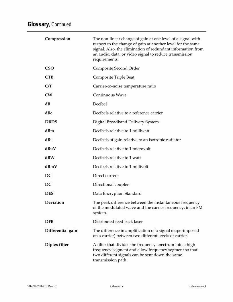
78-748704-01 Rev C Glossary Glossary-3
Glossary, Continued
Compression The non-linear change of gain at one level of a signal with respect to the change of gain at another level for the same signal. Also, the elimination of redundant information from an audio, data, or video signal to reduce transmission requirements.
CSO Composite Second Order
CTB Composite Triple Beat
C/T Carrier-to-noise temperature ratio
CW Continuous Wave
dB Decibel
dBc Decibels relative to a reference carrier
DBDS Digital Broadband Delivery System
dBm Decibels relative to 1 milliwatt
dBi Decibels of gain relative to an isotropic radiator
dBuV Decibels relative to 1 microvolt
dBW Decibels relative to 1 watt
dBmV Decibels relative to 1 millivolt
DC Direct current
DC Directional coupler
DES Data Encryption Standard
Deviation The peak difference between the instantaneous frequency of the modulated wave and the carrier frequency, in an FM system.
DFB Distributed feed back laser
Differential gain The difference in amplification of a signal (superimposed on a carrier) between two different levels of carrier.
Diplex filter A filter that divides the frequency spectrum into a high frequency segment and a low frequency segment so that two different signals can be sent down the same transmission path.

Glossary-4 Glossary 78-748704-01 Rev C
Glossary, Continued
Distribution System Part of a cable system consisting of trunk and feeder cables used to carry signals from headend to subscriber terminals.
Downconverter A device that converts an input signal to a lower frequency output signal.
Down link A transmission path carrying information from a satellite or spacecraft to earth.
DP Data processing
DPU Digital processing unit
DSP Digital signal processor
DSR Digital Storage and Retrieval System
D to U Desired to undesired signal ratio
DTMF Dual Tone Multiple Frequency
Duplexer A device that permits the connection of both a receiver and a transmitter to a common antenna.
DVM Digital voltmeter
DWDM Dense Wave Division Multiplexing
ECL Emitter coupled logic
ECM Entitlement Control Message
EDFA Erbium Doped Fiber Amplifier
EEPROM Electrically Erasable Programmable Read-Only Memory
EIA Electronics Industry Association
EMI Electromagnetic interference
Emission designer An FCC or CCIR code that defines the format of radiation from a transmitter.
EPROM Erasable Programmable Read-Only Memory
EQ Equalizer
78-748704-01 Rev C Glossary Glossary-5
Glossary, Continued
Equalization The process of compensating for an undesired result. For example, equalizing tilt in a distribution system.
ERP Effective radiated power
FAOC Frequency agile output converters
FET Field-effect transistor
FIFO First in, first out
FM Frequency modulation
Forward path Signal direction from the headend to the set-top terminal.
FP Fabry-Perot laser
FPGA Field Programmable Gate Array. A flexible logic device with thousands of gates
Fiber A single strand of glass used as an optical transmission medium; or a bundle of glass strands in a CATV system.
Frequency The number of similar shapes in a unit of time. For example, the number of sine waves moving past a fixed point in a second.
Frequency Agile The ability to change from one frequency to another without changing components.
Frequency Modulation A system of modulation where the instantaneous radio frequency of the carrier varies in proportion to the instantaneous amplitude of the modulating signal while the amplitude of the radio frequency carrier is independent of the amplitude of the modulating signal.
Frequency Response The effect that changing the frequency has on the magnitude of a signal.
Frequency Stability A measure of the departure from nominal frequency value of a signal, with respect to time, temperature, or other influence.
FSM Field strength meter
FSK Frequency-shift keying

Glossary-6 Glossary 78-748704-01 Rev C
Glossary, Continued
ft-lb Foot-pound
FTP File Transfer Protocol
Gain An increase in signal relative to a reference
Gbps Gigabits per second
Headend Location and equipment that receives data from a satellite (or other) source and reformats that data for input to a broadband distribution network.
HEDA Headend Driver Amplifier
HGD High Gain Dual
Hertz A unit of frequency equal to one cycle per second.
Hetrodyne Changing the frequency of a signal by mixing it with another signal to get the sum and difference of the two.
I/O Input/output
IC Integrated circuit
ICIM Intelligent Communications Interface Module
ICP Internal Control Program. A series of policies to protect company sensitive and export controlled information.
IDR Intermediate Data Rate
IEC International Electro-technical Commission
IF Intermediate frequency
IFL Interfacility link
IP Internet protocol
ITU International Telecommunications Union
Kbps Kilobits per second
in-lb Inch-pound
LCD Liquid crystal display

78-748704-01 Rev C Glossary Glossary-7
Glossary, Continued
LCI Local craft interface
LED Light-emitting diode
LIFO Last-in, first-out
LNA Low-noise amplifier
LNB Low-noise block converter
LNC Low-noise converter
Mbps Megabits per second
MCU Master Control Unit
Multipath (multipath transmission)
The phenomenon which results from a signal traveling from point to point by more than one path so that several copies of the signal arrive at the destination at different times or at different angles.
mux multiplexed
Nanosecond 1 thousandth of a microsecond
Nm Newton meter
NIU Network Interface Unit
Node A branching or exchange point.
OEM Original equipment manufacturer
OOB Out of band
OIM Optical interface module
OSM Optical-Sub module
PCB Printed circuit board
PCM Pulse code modulation
PDI Pressure differential indicator
PDU Power distribution unit
PIN PIN Photodiode - A standard photodiode. (PIN stands for Positive doped - Intrinsic region - Negative doped and has to do with the chip architecture)

Glossary-8 Glossary 78-748704-01 Rev C
Glossary, Continued
PLL Phase Lock Loop. An electronic servo system controlling an oscillator to maintain a constant phase angle relative to a reference signal.
PROM Programmable Read Only Memory
PWB Printed wiring board
QAM Quadrature Amplitude Modulation
QPR Quadrature Partial Response
QPSK Quadrature Phase-Shift Keying
RC Reverse conditioner
Reverse path Signal flow direction toward the headend.
RF Radio frequency
RF Bypass A bypass feature that allows subscribers to view a clear analog channel while recording a digital or analog channel on a VCR.
RFI Radio frequency interference
RMA Return material authorization
RMS Root Mean Square
Router A data communications device which examines a packet and routes the packet to an output port appropriate to the packet destination.
RS Remote Sensing
RX Receive or receiver
SA Spectrum analyzer
SAM Signal analysis meter
SAT Site acceptance test
S-band The group of frequencies between 2 and 4 GHz.
SET Secure electronic transaction

78-748704-01 Rev C Glossary Glossary-9
Glossary, Continued
Scattering Random directional change of a wave or part of a wave caused by an irregular reflecting surface or by passing through an inhomogeneous transmission medium.
SLM Signal level meter
SM Status monitor
SMC Status monitoring and control
SMIU Status Monitor Interface Unit
SMU Server Management Unit
S/N or SNR Signal-to-noise ratio
SNMP Simple Network Management Protocol
SONET Synchronous optical network
SP Splitter. It is a device that divides power from an input to deliver multiple outputs or combines multiple input into one output.
Spread Spectrum A modulation technique to spread a narrow band signal over a wide band of frequencies.
Spurious Anything other than the desired result
SSPA Solid-state power amplifier
Sweep generator A signal source which can automatically vary its frequency continuously from one frequency to another.
Synchronous transmission
A method of sending information over a path and separating discrete characters and symbols by a precise separation in time.
TEC Thermo-electric cooler
TCP/IP Transmission control protocol/internet protocol
TDM Time division multiplexing
TNCS Transmission Network Control System
Torque Force applied to bolt or screw to tighten the device.
TS Transport Stream

Glossary-10 Glossary 78-748704-01 Rev C
Glossary, Continued
TTCN True tilt correction network
Tx Transmit or transmitter
UBT Unbalanced triple
UPS Un-interruptible power supply
Upstream Signal transmission toward the headend
UTP Unshielded twisted pair
uV One millionth of a volt (microvolt)
V Volt
V AC Volts alternating current
VBR Variable bit rate
VCA Voltage controlled attenuator
V DC Volts direct current
VOD Video-on-demand
VOM Volt ohm meter
W Watts
WDM Wave Division Multiplexing
YEDFA Ytterbium/erbium doped fiber amplifier

Index
78-748704-01 Rev C Index-1
A alarms
checking using ICIM, 3-27 checking using LCI, 4-20
B bdr digital reverse multiplexing system, 1-3 block diagram
ICIM, 3-2 receive processor, 1-4
C chassis illustration, 2-5 chassis, communications connections, 2-15 chassis-to-chassis communications, 2-15 communications, chassis-to-chassis, 2-15 compliance
electromagnetic compatability, viii laser & electrical, viii
configuration options, 1-10 saving using ICIM, 3-33 using LCI, 4-19
connections optical cables, 2-12 RF cable, 2-6
connectors alarms in, 2-16 cleaning optical, 5-12 input, 1-3
D device
details window, 4-12 properties, 4-22 tree overview, 4-11
E external connections, 1-13
F fiber fish tool, 2-10
I ICIM
block diagram, 3-2 front panel, 3-3 front panel features, 3-4 front panel illustration, 3-3 function, 3-2 key pad, 3-5 LCD, 3-4 operating, 3-14 password, 3-8
indicator alarm, 1-5 power on, 1-5
installations processor, 2-8, 3-2 receiver, 2-13
L LCI
computer requirements, 4-3 configuring, 4-17 connecting to chassis, 4-8 operating status, 4-15 starting software, 4-9
M manufacturing data
checking, 3-30 display, 3-31
menu ALARM using ICIM, 3-28

Index
Index-2 78-748704-01 Rev C
CONFIG using ICIM, 3-24 ICIM, 3-15 ICIM menu structure, 3-16 MAIN using ICIM, 3-14 software menu structure, 3-17
module maintenance, 5-2
O operating environment, 2-3 optical connectors, 5-12 output muting, 1-10
P parameters
configuring with ICIM, 3-23 monitored, 3-18
password changing using ICIM, 3-11 disabling using ICIM, 3-13 function with ICIM, 3-7 ICIM, 3-6 re-entering using ICIM, 3-9 rejected by ICIM, 3-10 using for the first time, 3-8
PECL, 1-6
R receive processor
back panel, 1-7 block diagram, 1-4 configuration summary, 1-9 overview, 1-2
receiver front panel, 1-8 redundancy interface panel
features, 2-22 introduction, 2-21 master/slave connections, 2-26
redundant mode, 1-9
S safety
laser, ix precautions, vi, vii, viii
status checking using ICIM, 3-18 using LCI, 4-15
T troubleshooting
alarm conditions, 5-4 general, 5-3
W warning
labels, x radiation, ix

Cisco Systems, Inc. 5030 Sugarloaf Parkway, Box 465447 Lawrenceville, GA 30042
678 277-1120 800 722-2009
www.cisco.com This document includes various trademarks of Cisco Systems, Inc. Please see the Notices section of this document for a list of the Cisco Systems, Inc. trademarks used in this document. Product and service availability are subject to change without notice. © 2002, 2008, 2012 Cisco and/or its affiliates. All rights reserved. October 2012 Printed in USA
Part Number 78-748704-01 Rev C