pro 1 0 service m anu l - frank's hospital workshop · service m anu l. p r o 1 0 0 0 s e r v...
TRANSCRIPT

PRO 1000SERVICE MANUAL

PRO
1000 SERV
ICE M
AN
UA
LD
INA
MA
P
DINAMAP PRO 1000 Monitor
Service Manual

List of Effective Pages Part No./Rev. Page No. Date of Latest Revision 2008072 All Original Oct. 2001)
U.S. Patent 5,170,795 U.S. Patent 4,349,034 U.S. Patent 5,052,397 U.S. Patent 4,360,029 U.S. Patent 4,754,761 U.S. Patent 4,501,280 U.S. Patent 4,638,810 U.S. Patent 4,546,775 U.S. Patent 4,543,962 U.S. Patent 5,518,000 U.S. Patent 5,704,362 Patents Pending
CAUTION: Federal (U.S.A.) law restricts this device to sale by or on the order of a health care practitioner The content of this document, including all figures and drawings, is proprietary information of General Electric Medical Systems Information Technologies, provided solely for purposes of operation, maintenance or repair of PRO 1000 Monitors. Dissemination for other purposes or copying thereof without the prior written consent of General Electric Medical Systems Information Technologies, Tampa, Florida, is prohibited. Illustrations may show design models; production units may incorporate changes. CRITIKON 2001 TAMPA, FL 33614 Printed in the U.S.A. All rights reserved. United States Critikon, L.L.C. 4502 Woodland Corporate Boulevard Tampa, FL 33614 EU Representative GE Medical Systems Information Technologies GmbH Munzinger Strasse, Freiburg, Germany
ii
TABLE OF CONTENTS SECTION 1 INTRODUCTION 1.1. Scope of Manual........................................................................................1-1 1.2. Manual Changes .......................................................................................1-2 1.3 Service Policy ............................................................................................1-2
1.3.1 Extended Warranties .................................................................................1-2 1.3.2 Assistance .................................................................................................1-2 1.3.3 Service ......................................................................................................1-3 1.3.4 Service Loaners.........................................................................................1-4 1.3.5 Repair Parts ..............................................................................................1-4 1.3.6 Replacement Accessories .........................................................................1-5
1.4 Product Description ...................................................................................1-5 1.4.1 General Description...................................................................................1-5 1.4.2 Storage Batteries.......................................................................................1-6
Table 1-1 Specifications..........................................................................................1-7
SECTION 2. PRODUCT DESCRIPTION 2.1. Introduction ................................................................................................2-3 2.2. Product Configurations ..............................................................................2-3 2.3. Controls, Indicators, and Connectors.........................................................2-3 2.3.1. PRO Monitor Rear Panel Connections ......................................................2-4 2.3.2. Front Panel Controls and Indicators...........................................................2-5 2.4. Host Port Connector (rear panel) ...............................................................2-7 2.4.1. Pin Assignments ........................................................................................2-7 2.5. Compatible Parts .......................................................................................2-8 2.6. Specifications.............................................................................................2-9 2.6.1. Power Requirements .................................................................................2-9 2.6.2. Environmental ............................................................................................2-9 2.6.3. Mechanical.............................................................................................. 2-10 2.6.4. NIBP ....................................................................................................... 2-10 2.6.5. Temperature ........................................................................................... 2-10 2.6.6. SpO2....................................................................................................... 2-11 2.6.7. ECG ........................................................................................................ 2-12
SECTION 3. PRINCIPLES OF OPERATION 3.1. Introduction ...............................................................................................3-3 3.2. Overall Principle Of Operation ..................................................................3-3
3.2.1. Nellcor SPO2.............................................................................................3-3 3.2.2. Cuff Blood Pressure (BP) and Pulse .........................................................3-3 3.2.3. Alaris Oral and Rectal Thermometry .........................................................3-4 3.2.4. ECG with Heart Rate and Respiration .......................................................3-4
iii

3.2.5. Host Communication Ports........................................................................3-4 3.3. Functional Description ..............................................................................3-5
3.3.1. PSU PWA..................................................................................................3-5 3.3.2. Mains Converter Module ...........................................................................3-6 3.3.3. Main Board ................................................................................................3-6 3.3.4. Keyboard PWA..........................................................................................3-7 3.3.5. ECG PWA .................................................................................................3-8 3.3.6. Pneumatic Control .....................................................................................3-8 3.3.7. LCD Assembly...........................................................................................3-9 3.3.8. Printer (Optional) .................................................................................... 3-10
List of Figures 3-1 General System Diagram .............................................................................. 3-12
SECTION 4. GENERAL MAINTENANCE 4.1. Introduction................................................................................................4-3 4.2. Configuring the PRO 1000 Monitor for the First Time................................4-3
4.2.1 Unpacking and Preparation for Installation................................................4-3 4.2.2 Set the Date and the Clock........................................................................4-5 4.2.3 Parameter Level Functional Testing ..........................................................4-6
4.3. Periodic Maintenance ................................................................................4-7 4.3.1. As Required...............................................................................................4-7
4.3.1.1 Integrity of Cuffs and Hoses ..................................................................4-7 4.3.1.2 External DC Supply and Battery ............................................................4-7 4.3.1.3 Cleaning of Accessories ........................................................................4-7 4.3.1.4 Long Term Storage................................................................................4-8
4.3.2 Annual Procedures ....................................................................................4-8 4.4. Care of Storage Batteries ..........................................................................4-9 4.4.1. Procedures for First Use............................................................................4-9 4.4.2 Battery Charging........................................................................................4-9 4.5 Safety Resistance Testing...................................................................... 4-12 4.6. Alarm Code Interpretation ...................................................................... 4-14
4.6.1. System Failures...................................................................................... 4-14 4.6.2. Hardware Errors ..................................................................................... 4-15 4.6.3. Parameter Failures ................................................................................. 4-15
4.6.3.1 ECG/RESP/TEMP Errors ................................................................... 4-15 4.6.3.2 NIBP Messages.................................................................................. 4-15 4.6.3.3 Temperature Messages...................................................................... 4-16 4.6.3.4 SpO2 Messages ................................................................................. 4-16
4.7. Service Mode Operation......................................................................... 4-16 4.7.1 SpO2 Tests ............................................................................................ 4-19 4.7.2 NIBP Tests ............................................................................................. 4-20
4.7.2.1 Leak Test............................................................................................ 4-21 4.7.2.2 NIBP Calibration Check ...................................................................... 4-23
iv

4.7.2.3 Pressure Recalibration ....................................................................... 4-24 4.7.2.4 Overpressure Test.............................................................................. 4-25
4.7.3 EKG Tests .............................................................................................. 4-27 4.7.4 Temp Tests ............................................................................................ 4-28 4.7.5 Recorder Tests ....................................................................................... 4-30 4.7.6 Battery Tests .......................................................................................... 4-31 4.7.7 Test Failsafe Logic ................................................................................. 4-32 4.7.8 Keypad LED Test ................................................................................... 4-33 4.7.9 Keypad Key Test .................................................................................... 4-33 4.7.10 Sound Test ............................................................................................. 4-33 4.7.11 Turn off the System................................................................................ 4-33
4.8 Service Mode Exit................................................................................... 4-33 Chapter 4 Appendices Test Record ......................................................................................... Appendix A Monitor Configuration Log ................................................................... Appendix B
SECTION 5 ASSEMBLY DRAWINGS & ELECTRICAL SCHEMATICS Assembly Drawings (Monitor Assembly & Disassembly) Front Case 1 ......................................................................................................5-1/2 Front Case 2 ......................................................................................................5-3/4 Rear Case 1.......................................................................................................5-5/6 Rear Case 2.......................................................................................................5-7/8 Electrical Schematics ECG Board – 315589........................................................................ 5-9 through 5-18 Main Board – 315592...................................................................... 5-19 through 5-42 Power Supply Board – 315593 ....................................................... 5-43 through 5-52 Keyboard ........................................................................................................ 5-53/54 Probe Warmer ................................................................................................ 5-55/56
v

SECTION 1 INTRODUCTION Contents 1.1. Scope of Manual ..............................................................................................1-1 1.2. Manual Changes..............................................................................................1-2 1.3 Service Policy ...................................................................................................1-2
1.3.1 Extended Warranties...................................................................................1-2 1.3.2 Assistance...................................................................................................1-2 1.3.3 Service ........................................................................................................1-3 1.3.4 Service Loaners ..........................................................................................1-4 1.3.5 Repair Parts ................................................................................................1-4 1.3.6 Replacement Accessories...........................................................................1-5
1.4 Product Description...........................................................................................1-5 1.4.1 General Description.....................................................................................1-5 1.4.2 Storage Batteries.........................................................................................1-6
Table 1-1 Specifications..........................................................................................1-7

This page intentionally left blank.

SECTION 1. INTRODUCTION 1.1 SCOPE OF MANUAL
This Service Manual provides service and parts repair information about the DINAMAP PRO 1000 Monitor. This manual is intended for use by trained service technicians who are familiar with electromechanical devices and digital and analog circuit techniques.
WARNING
CAUTION
To reduce the risk of electric shock, do not remove cover or back of any component. Refer servicing to qualified service personnel.
Only qualified service-technicians should perform repairs to this equipment. Voltages dangerous to life exist in this unit. Take care when servicing power supply and display assembly.
For information about operating the Monitor in a clinical environment, refer to the separate Operation Manual.
This Service Manual consists of the following four sections:
Section 1 describes this volume and tells you how to use it. Information is
also provided about the physical and functional characteristics of the Monitor, and how to get assistance in the event the unit fails to function properly.
Section 2 provides a general overview of the PRO 1000 including user
controls, external connections, and product/ parameter specifications.
Section 3 presents principles of operation for the Monitor, including an overall system description and principles of operation at the component level.
Section 4 provides information about periodic and corrective maintenance of the Monitor. Procedures include module performance tests and calibration procedures. Information is provided to facilitate isolating faults to the subassembly level.
Section 5 provides component information about the Monitor, including disassembly and reassembly procedures, parts lists, and assembly drawings, and electrical schematics.
1-1

1.2 MANUAL CHANGES
If, in the normal use of this manual, you notice errors, omissions, incorrect data, or if you can suggest comments that may help improve this manual, please complete the Publications Change Request form in the back of this manual. Submit the form to:
General Electric Medical Systems Information Technologies Technical Publications 4502 Woodland Corporate Boulevard Tampa, Florida 33614
Changes to the Service Manual, either in response to user input or to reflect continuing product improvements, are accomplished through reissue. Changes occurring between reissues are addressed through Change Information Sheets and replacement pages. If a Change Information Sheet does not accompany your manual, the manual is correct as printed.
1.3 SERVICE POLICY
The warranty for this product is enclosed with the product in the shipper carton. All repairs on products under warranty must be performed or approved by Product Service personnel. Unauthorized repairs will void the warranty. Only qualified electronics service personnel should repair products not covered by warranty.
1.3.1 Extended Warranties
Extended warranties may be purchased on most products. Contact your Sales Representative for details and pricing.
1.3.2 Assistance
If the product fails to function properly, or if assistance, service or spare parts are required, contact Customer Support. Before contacting Customer Support, it is helpful to attempt to duplicate the problem and to check all accessories to ensure that they are not the cause of the problem. If you are unable to resolve the problem after checking these items, contact General Electric Medical Systems Information Technologies. Prior to calling, please be prepared to provide:
1-2

• product name and model number • a complete description of the problem
If the repair parts or service are necessary, you will also be asked to provide
• the product serial number • the facility's complete name and address • a purchase order number if the product is to need of repair or when you
order spare parts • the facility's account number, if possible • the 6-digit part number for spare or replacement parts
1.3.3 Service
If your product requires warranty, extended warranty or non-warranty repair service, call Customer Support and a representative will assist you. Estimates for non-warranty repairs are provided at no charge; however, the product must be sent to the General Electric Medical Systems Service Center in order to provide you with an estimate.
To facilitate prompt service in cases where the product has external chassis or case damage, please advise the Customer Support representative when you call.
The Customer Support representative will record all necessary information and will provide you with a Return Merchandise Authorization Number (RMA). Prior to returning any product for repair, you must have a RMA number. Contact technical support at 1-877-274-8456
Monday through Friday, 8:00 a.m. to 7:00 p.m. EST, excluding holidays.
Packing Instructions Follow these recommended packing instructions.
• Remove all hoses, cables, sensors, and power cords from the monitor
before packing. • Pack only the accessories you are requested to return; place them in a
separate bag and insert the bag and the product inside the shipping carton. • Use the original shipping carton and packing materials, if available.
If the original shipping carton is not available
• Place the product in a plastic bag and tie or tape the bag to prevent
loose particles or materials from entering openings such as hose ports.
1-3

• Use a sturdy corrugated container to ship the product; tape securely to seal the container for shipping.
• Pack with 4 to 6 in. of padding on all sides of the product.
Insurance Insurance is at the customer's discretion. The shipper must initiate claims for damage to the product.
1.3.4 Service Loaners
A loaner unit is provided at no charge during the service life of the product when we perform the repair service. Within 48 hours of your request, a loaner will be shipped to your facility.
• General Electric Medical Systems will pay shipping charges for a loaner
sent to the customer for product repairs under the warranty. • Shipping charges for a loaner sent to the customer for product repairs not
under warranty will be billed to the customer. • The customer will pay shipping charges to return a loaner.
All loaners provided to customers must be returned within the specified time stated on the loaner agreement or a rental fee will be incurred.
1.3.5 Repair Parts
Repair parts can be ordered from General Electric Medical Systems:
Via phone 1-877-274-8456, or
Via FAX 1-813-887-2430
Exchange replacement assemblies such as Circuit Board Assemblies also are available; ask the Customer Support representative for details.
Please allow one working day for confirmation of your order. All orders must include the following information. • Facility's complete name, address, and phone number • FAX number • Your purchase order number • Your account number
1.3.6 Replacement Accessories
1-4

Replacements such as hoses, sensors, etc. must be purchased from General Electric Medical Systems at 1-877-274-8456. Please have the 4-digit or 6-digit Reorder/Product Code of the item you wish to order, your purchase order and account number available.
1.4 PRODUCT DESCRIPTION
The Monitor and storage batteries are described below. Refer to Table 1-1 for specifications.
1.4.1 General Description
The DINAMAP PRO 1000 is designed for patient monitoring in acute care settings such as critical care, emergency room, radiology, labor and delivery, and operating room. It allows the clinician to view, record, and recall clinical data derived from each parameter. This data includes heart rate, respiration rate, oxygen saturation, noninvasive blood pressure, and temperature. Alarm limit conditions are also detected.
The recorder provides numeric and waveform printouts of monitored data. Up to 2 waveforms can be traced simultaneously. Each monitor can monitor one patient at the bedside.
Patient sensor connections are made at the side of the unit, and network and device connectors are at the rear.
Indicators for external DC operation (from AC mains), battery operation, and battery charging are at the front of the unit.
At the time of publication, the available functioning parameters included the following:
• NIBP • Nellcor™ Pulse oximetry (SpO2) • 3-lead ECG, with respirations • 2-channel thermal recorder • Alaris™ Oral and Rectal thermometry
The PRO 1000 Monitor series uses a TFT active-matrix-color liquid display.
The 10.4” diagonal display area contains 640 x 480 pixels and can display 262,144 colors simultaneously.
1-5
The LCD has the following specific characteristics. These are neither defects nor malfunctions:
• The ambient temperature may affect the display condition of the LCD. • The LCD uses replaceable cold cathode tubes for backlighting. Optical
characteristics, like luminance or uniformity will change during time. • Uneven brightness and/or small spots may be noticed depending on
different display patterns.
Other DINAMAP PRO 1000 features include:
• The ability to uses industry standard accessories • Remote alarm capability • An intuitive graphical user interface, with a simple Select Knob that moves
the user through menus in a logical, and easy to understood format • Five single-function keys for quick access to Alarm Silence, Record,
Freeze, NIBP Start/Stop, and STAT NIBP
1.4.2 Storage Batteries
The PRO 1000 Monitor operates from AC mains power, an external DC power supply, or from the internal Nickel Metal Hydride storage battery. When external DC power becomes available, the system rapidly switches from battery power to external power.
1-6

Table 1-1. Specifications Mechanical Monitor 14.8 in (H) x 8.7 in (D) x 13.8 in (W)
37.0 cm (H) x 21.8 cm (D) x 34.4 cm (W) Weight Less than 12 lb (9.5 kg) Environmental* Operating Temperature +41º F to +104º F (+5° C to +40° C) Storage Temperature -40º F to +158º F (-20º C to +60º C) Operating Humidity 5% to 95%, noncondensing Storage Humidity 5% to 95%, noncondensing Operating Atmospheric Pressure 700 hPa to 1060 hPa Storage Atmospheric Pressure 500 hPa to 1060 hPa Electrical Power Supply The PRO 1000 Monitor can be operated from AC power, external DC power, or the rechargeable internal battery. AC Input Voltage 120 - 240 AC Input Frequency 50 - 60 Hz AC Input Power 60 - 120 Volt Amperes AC Power Cable Detachable, 16-gauge, 10 ft (3 meters) long DC Input Voltage 18-24 V (supplied from a source conforming to IEC 601-1) DC Input Power 60 Watts (supplied from a source conforming to IEC 601-1) Internal Battery 12 Volts, nickel-metal-hydride (NiMH) Battery Life 120 minutes (± 10 minutes) using fully charged internal
battery, under specified load ** Charge time, internal charger
The PRO Monitor typically charges the battery to within 90% capacity within 3 hours.
Fuse (Battery) 10A 250V slow-blow * The Monitor may not meet Performance Specifications (ANSI/AAMI SP10) if it
is stored or used out of environmental specification ranges. ** Monitor shall be capable of operating on battery power for 2 hours minimum
(NIBP @ 5 min., ECG/Resp. SpO2, temp, dual channel recording once every 20 minutes.
1-7

SECTION 2. PRODUCT DESCRIPTION
CONTENTS 2.1. Introduction ................................................................................................ 2-3 2.2. Product Configurations .............................................................................. 2-3 2.3. Controls, Indicators, and Connectors......................................................... 2-3 2.3.1. PRO Monitor Rear Panel Connections ...................................................... 2-4 2.3.2. Front Panel Controls and Indicators........................................................... 2-5 2.4. Host Port Connector (rear panel) ............................................................... 2-7 2.4.1. Pin Assignments ........................................................................................ 2-7 2.5. Compatible Parts ....................................................................................... 2-8 2.6. Specifications............................................................................................. 2-9 2.6.1. Power Requirements ................................................................................. 2-9 2.6.2. Environmental ............................................................................................ 2-9 2.6.3. Mechanical............................................................................................... 2-10 2.6.4. NIBP ........................................................................................................ 2-10 2.6.5. Temperature ............................................................................................ 2-10 2.6.6. SpO2 ........................................................................................................ 2-11 2.6.7. ECG .........................................................................................................2-12
2-1

This page intentionally left blank.
2-2
SECTION 2. PRODUCT DESCRIPTION
2.1. INTRODUCTION DINAMAP PRO Monitors provide non-invasive determination of systolic blood pressure, diastolic blood pressure, mean arterial pressure, pulse rate, 3-lead ECG, temperature, and oxygen saturation. These portable AC and DC operated monitors are primarily intended for use in hospital acute care settings such as outpatient surgery, accident and emergency, labor and delivery, GI/endoscopy, and medical/surgical units.
2.2. PRODUCT CONFIGURATIONS
Each PRO Monitor is supplied with an accessory pack. The contents of the pack vary according to model. Unpack the items carefully, and check them against the checklists enclosed within the accessory boxes. If an accessory is missing or if an item is in a nonworking condition, contact Critikon immediately. It is recommended that all the packaging be retained, in case the PRO Monitor must be returned for service in the future.
2.3. CONTROLS, INDICATORS, AND CONNECTORS
Descriptions of the items shown are listed on the pages that follow. For symbol definitions, refer to paragraph: 2.3.2 of this section.
2-3
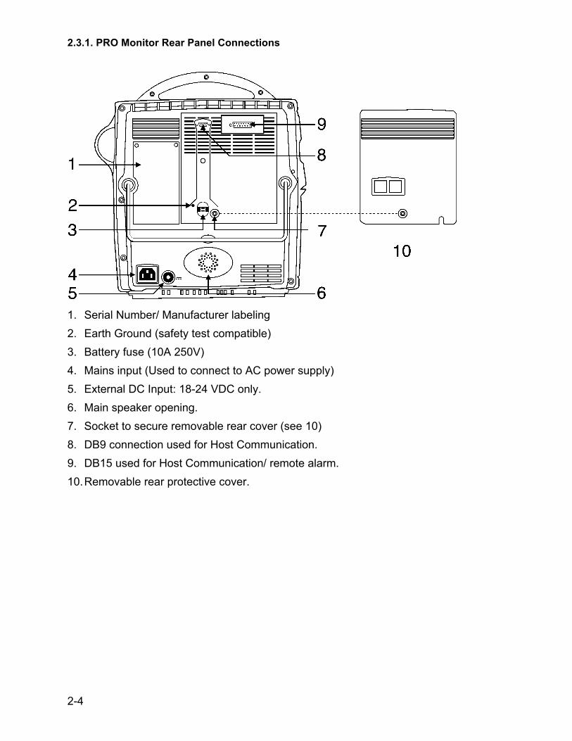
2.3.1. PRO Monitor Rear Panel Connections
1. Serial Number/ Manufacturer labeling 2. Earth Ground (safety test compatible) 3. Battery fuse (10A 250V) 4. Mains input (Used to connect to AC power supply) 5. External DC Input: 18-24 VDC only. 6. Main speaker opening. 7. Socket to secure removable rear cover (see 10) 8. DB9 connection used for Host Communication. 9. DB15 used for Host Communication/ remote alarm. 10. Removable rear protective cover.
2-4
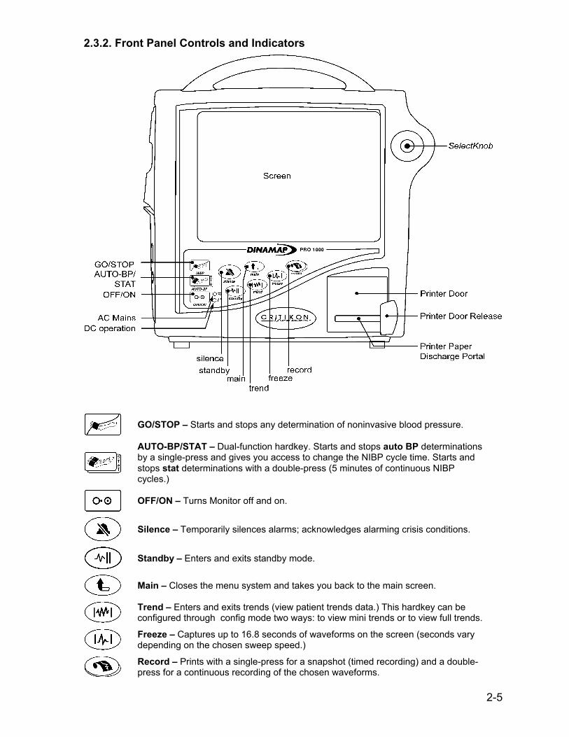
2.3.2. Front Panel Controls and Indicators
GO/STOP – Starts and stops any determination of noninvasive blood pressure.
AUTO-BP/STAT – Dual-function hardkey. Starts and stops auto BP determinations by a single-press and gives you access to change the NIBP cycle time. Starts and stops stat determinations with a double-press (5 minutes of continuous NIBP cycles.)
OFF/ON – Turns Monitor off and on.
Silence – Temporarily silences alarms; acknowledges alarming crisis conditions.
Standby – Enters and exits standby mode.
Main – Closes the menu system and takes you back to the main screen.
Trend – Enters and exits trends (view patient trends data.) This hardkey can be configured through config mode two ways: to view mini trends or to view full trends.
Freeze – Captures up to 16.8 seconds of waveforms on the screen (seconds vary depending on the chosen sweep speed.)
Record – Prints with a single-press for a snapshot (timed recording) and a double-press for a continuous recording of the chosen waveforms.
2-5

Optional Components Note: Interconnected equipment must be installed by a qualified service person. Symbols
CE Mark
External Communications Port Connector
Attention, consult accompanying documents
Type CF applied part
Battery in use
Canadian Standards Association
Storage temperature
External AC or DC power indicator
External DC power input
External AC power input
Keep away from heat
This way up
Keep dry
Fragile, handle with care
SN Serial number
REF Catalog number
Predictive temperature
Functional earth terminal (ground lug)
Serial Port 1
Serial Port 2
Ethernet Connector
2-6
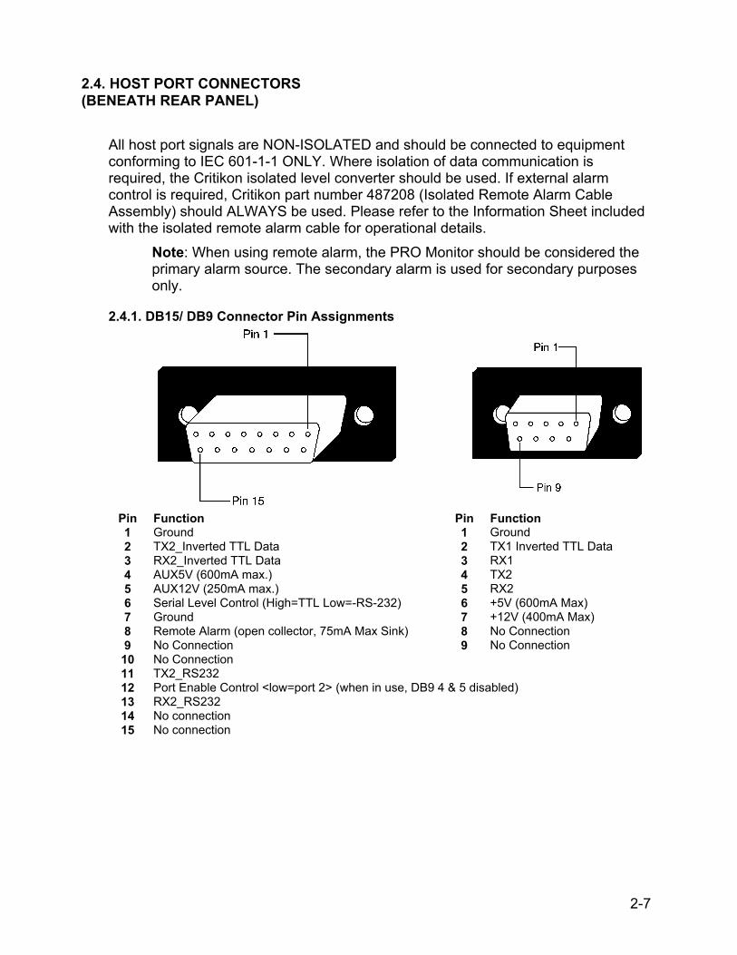
2.4. HOST PORT CONNECTORS (BENEATH REAR PANEL)
All host port signals are NON-ISOLATED and should be connected to equipment conforming to IEC 601-1-1 ONLY. Where isolation of data communication is required, the Critikon isolated level converter should be used. If external alarm control is required, Critikon part number 487208 (Isolated Remote Alarm Cable Assembly) should ALWAYS be used. Please refer to the Information Sheet included with the isolated remote alarm cable for operational details.
Note: When using remote alarm, the PRO Monitor should be considered the primary alarm source. The secondary alarm is used for secondary purposes only.
2.4.1. DB15/ DB9 Connector Pin Assignments
Pin Function Pin Function 1 Ground 1 Ground 2 TX2_Inverted TTL Data 2 TX1 Inverted TTL Data 3 RX2_Inverted TTL Data 3 RX1 4 AUX5V (600mA max.) 4 TX2 5 AUX12V (250mA max.) 5 RX2 6 Serial Level Control (High=TTL Low=-RS-232) 6 +5V (600mA Max) 7 Ground 7 +12V (400mA Max) 8 Remote Alarm (open collector, 75mA Max Sink) 8 No Connection 9 No Connection 9 No Connection 10 No Connection 11 TX2_RS232 12 Port Enable Control <low=port 2> (when in use, DB9 4 & 5 disabled) 13 RX2_RS232 14 No connection 15 No connection
2-7

2.5. COMPATIBLE PARTS The following parts are available from Customer Service. Description of Compatible Part Code SOFT-CUF, Cuff, Infant 2500 SOFT-CUF, Cuff, Child 2501 SOFT-CUF, Cuff, Small Adult 2502 SOFT-CUF, Cuff, Adult 2503 SOFT-CUF, Cuff, Large Adult 2504 SOFT-CUF, Cuff, Thigh 2505 SOFT-CUF, Cuff, Neonatal type 1 2521 SOFT-CUF, Cuff, Neonatal type 2 2422 SOFT-CUF, Cuff, Neonatal type 3 2523 SOFT-CUF, Cuff, Neonatal type 4 2524 SOFT-CUF, Cuff, Neonatal type 5 2525 DURA-CUF Cuff, Infant 2783 DURA-CUF Cuff, Child 2781 DURA-CUF Cuff, Small Adult 2779 DURA-CUF Cuff, Adult 2774 DURA-CUF Cuff, Large Adult 2791 DURA-CUF Cuff, Thigh 2796 DURA-CUF Cuff, Assortment cuff pack 2699 DURA-CUF Cuff, Child pack 2697 CLASSIC-CUF , Cuff, Infant 2618 CLASSIC-CUF, Cuff, Child 2613 CLASSIC-CUF, Cuff, Small Adult 2608 CLASSIC-CUF, Cuff, Adult 2603 CLASSIC-CUF, Cuff, Large Adult 2643 CLASSIC-CUF, Cuff, Thigh 2648 CLASSIC-CUF, Cuff, Neonatal type 1 2638 CLASSIC-CUF, Cuff, Neonatal type 2 2633 CLASSIC-CUF, Cuff, Neonatal type 3 2628 CLASSIC-CUF, Cuff, Neonatal type 4 2623 CLASSIC-CUF, Cuff, Neonatal type 5 2619 12 Foot (approx. 3.7 meters) Long Adult / Pediatric Hose 107365 24 Foot (approx. 7.3 meters) Long Adult / Pediatric Hose 107366 12 Foot (approx. 3.7 meters) Long Neonatal Hose 107368 12 Foot (approx. 3.7 meters) Long A/P Hose Quick Disconn. 107368 IVAC** Oral Temperature Probe 088012 IVAC** Rectal Temperature Probe 088013 IVAC** Temperature Probe Covers 088015 DINAMAP PRO Monitor Operation Manual 776995* DINAMAP PRO Monitor Service Manual 777358* Accessory Pole/Basket/Base 3215 Printer Paper (Box of 10) 089100 Power Cable 316579 NELLCOR*** SpO2 Extension Cable SCP10* NELLCOR Finger Sensor DS100A NIBP Calibration Kit 320246
* PRO Monitor unique parts ** IVAC is a trademark of ALARIS Medical Systems *** NELLCOR is a trademark of Mallinckrodt, Inc.
2-8

2.6. SPECIFICATIONS
0 0 8 6
This product conforms with the essential requirements of the Medical Device Directive. Accessories without the CE Mark are not guaranteed to meet the Essential requirements of the Medical Device Directive.
IPX1 The PRO Monitor is protected against vertically falling drops of water and conforms to the IEC 529 standard at level of IPX1. No harmful effects will come of vertically falling drops of water making contact with the monitor.
2.6.1. Power Requirements MAINS Protection against electrical shock - Class 1 AC INPUT VOLTAGE 115 / 230 VAC, 50 / 60 Hz (nominal),
90 ~ 253 VAC, 47 ~ 63 Hz (range) ALTERNATE SOURCES Protection against electrical shock – Class 1 DC INPUT VOLTAGE 24 VDC (nominal), 12-30 VDC from supplied power converter EXTERNAL DC FUSE Internal, auto-resetting. BATTERY 12 volt, 2.3 amp-hours. Protected by auto-resetting fuse.
Minimum operation time: 2 hours (5 minute auto cycle with adult cuff at 25°C (77°F) with power save mode enabled) from full charge. Time for full recharge: 1 hr 50 min from full discharge when the Monitor is switched off and 8 hrs when Monitor is switched on.
2.6.2. Environmental OPERATING TEMPERATURE + 5° C to + 40° C (+ 41° F to + 104° F) OPERATING ATMOSPHERIC PRESSURE RANGE 700 to 1060 hectoPascal
STORAGE TEMPERATURE – 20° C to + 50° C (– 4° F to + 122° F) STORAGE / TRANSPORTATION ATMOSPHERIC PRESSURE 500 to 1060 hectoPascal
HUMIDITY RANGE 0 % to 95 % non-condensing
RADIO FREQUENCY Complies with IEC Publication 601-1-2 (April 1993) Medical Electrical Equipment, Electromagnetic Compatibility Requirements and Tests, and CISPR 11 (Group 1, Class A) for radiated and conducted emissions.
INGRESS OF LIQUIDS The Monitor is protected against vertically falling drops of water and conforms with the IEC 529 standard at level of IPX1. No harmful effects will come of vertically falling drops of water making contact with the Monitor.
2-9
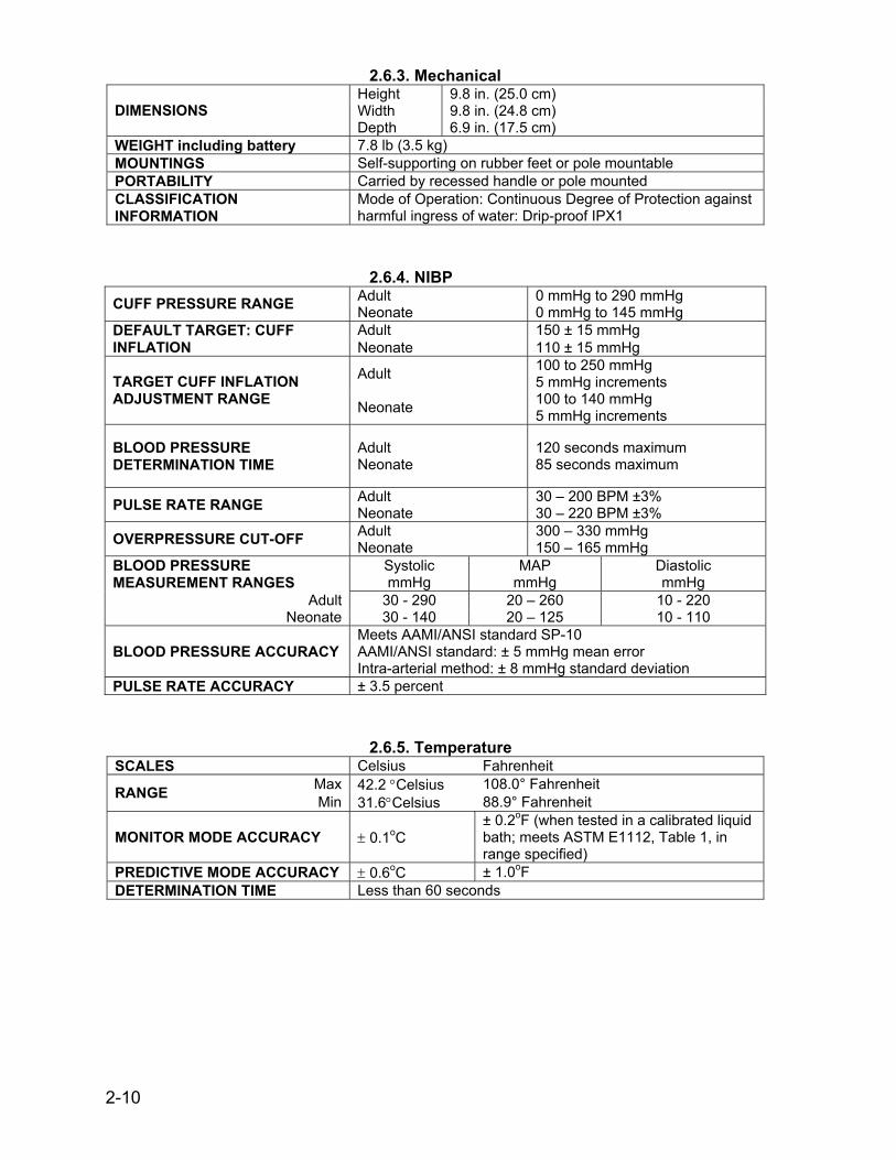
2.6.3. Mechanical Height 9.8 in. (25.0 cm) Width 9.8 in. (24.8 cm) DIMENSIONS Depth 6.9 in. (17.5 cm)
WEIGHT including battery 7.8 lb (3.5 kg) MOUNTINGS Self-supporting on rubber feet or pole mountable PORTABILITY Carried by recessed handle or pole mounted CLASSIFICATION INFORMATION
Mode of Operation: Continuous Degree of Protection against harmful ingress of water: Drip-proof IPX1
2.6.4. NIBP Adult 0 mmHg to 290 mmHg CUFF PRESSURE RANGE Neonate 0 mmHg to 145 mmHg Adult 150 ± 15 mmHg DEFAULT TARGET: CUFF
INFLATION Neonate 110 ± 15 mmHg Adult 100 to 250 mmHg
5 mmHg increments TARGET CUFF INFLATION ADJUSTMENT RANGE Neonate 100 to 140 mmHg
5 mmHg increments
BLOOD PRESSURE DETERMINATION TIME
Adult Neonate
120 seconds maximum 85 seconds maximum
PULSE RATE RANGE Adult Neonate
30 – 200 BPM ±3% 30 – 220 BPM ±3%
Adult 300 – 330 mmHg OVERPRESSURE CUT-OFF Neonate 150 – 165 mmHg BLOOD PRESSURE MEASUREMENT RANGES
Systolic mmHg
MAP mmHg
Diastolic mmHg
Adult 30 - 290 20 – 260 10 - 220 Neonate 30 - 140 20 – 125 10 - 110
BLOOD PRESSURE ACCURACY Meets AAMI/ANSI standard SP-10 AAMI/ANSI standard: ± 5 mmHg mean error Intra-arterial method: ± 8 mmHg standard deviation
PULSE RATE ACCURACY ± 3.5 percent
2.6.5. Temperature SCALES Celsius Fahrenheit
Max 42.2 °Celsius 108.0° Fahrenheit RANGE Min 31.6°Celsius 88.9° Fahrenheit
MONITOR MODE ACCURACY ± 0.1oC ± 0.2oF (when tested in a calibrated liquid bath; meets ASTM E1112, Table 1, in range specified)
PREDICTIVE MODE ACCURACY ± 0.6oC ± 1.0oF DETERMINATION TIME Less than 60 seconds
2-10
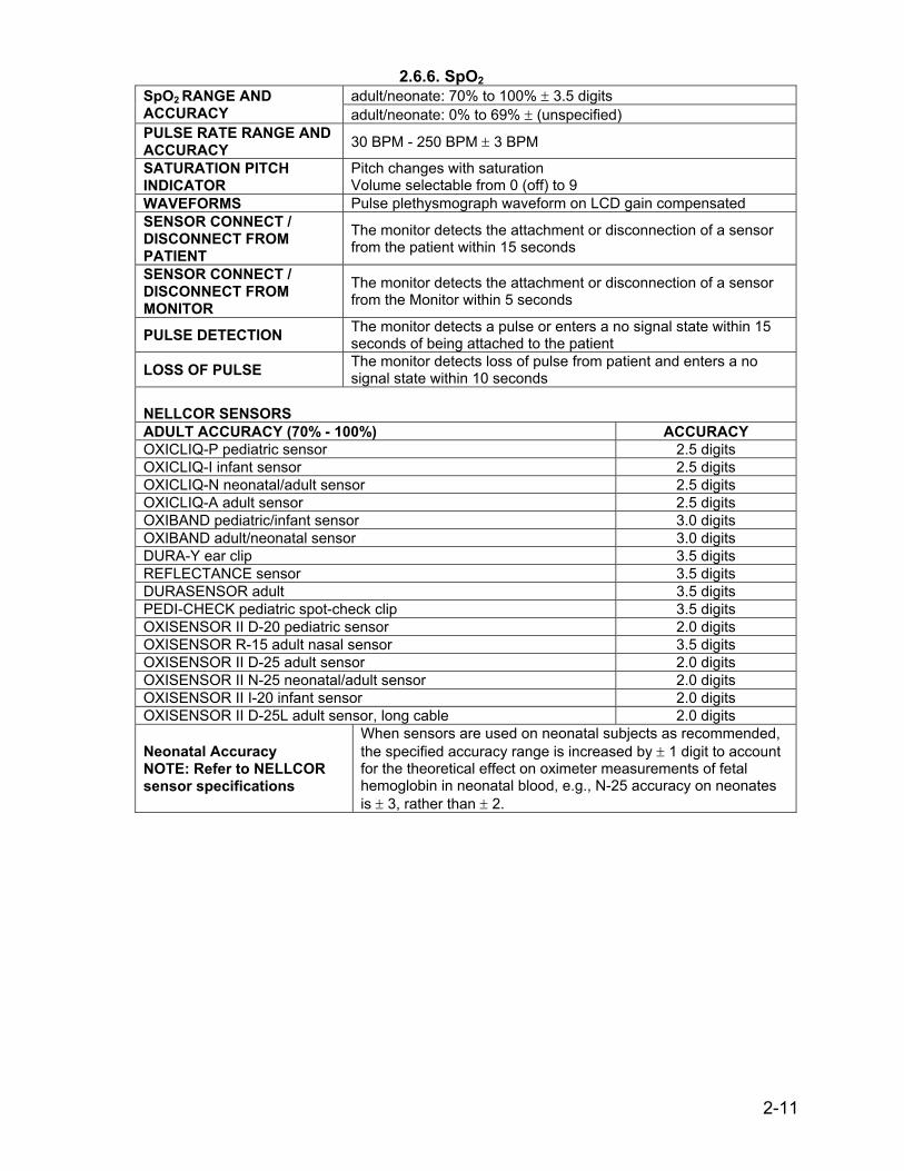
2.6.6. SpO2 adult/neonate: 70% to 100% ± 3.5 digits SpO2 RANGE AND
ACCURACY adult/neonate: 0% to 69% ± (unspecified) PULSE RATE RANGE AND ACCURACY 30 BPM - 250 BPM ± 3 BPM
SATURATION PITCH INDICATOR
Pitch changes with saturation Volume selectable from 0 (off) to 9
WAVEFORMS Pulse plethysmograph waveform on LCD gain compensated SENSOR CONNECT / DISCONNECT FROM PATIENT
The monitor detects the attachment or disconnection of a sensor from the patient within 15 seconds
SENSOR CONNECT / DISCONNECT FROM MONITOR
The monitor detects the attachment or disconnection of a sensor from the Monitor within 5 seconds
PULSE DETECTION The monitor detects a pulse or enters a no signal state within 15 seconds of being attached to the patient
LOSS OF PULSE The monitor detects loss of pulse from patient and enters a no signal state within 10 seconds
NELLCOR SENSORS ADULT ACCURACY (70% - 100%) ACCURACY OXICLIQ-P pediatric sensor 2.5 digits OXICLIQ-I infant sensor 2.5 digits OXICLIQ-N neonatal/adult sensor 2.5 digits OXICLIQ-A adult sensor 2.5 digits OXIBAND pediatric/infant sensor 3.0 digits OXIBAND adult/neonatal sensor 3.0 digits DURA-Y ear clip 3.5 digits REFLECTANCE sensor 3.5 digits DURASENSOR adult 3.5 digits PEDI-CHECK pediatric spot-check clip 3.5 digits OXISENSOR II D-20 pediatric sensor 2.0 digits OXISENSOR R-15 adult nasal sensor 3.5 digits OXISENSOR II D-25 adult sensor 2.0 digits OXISENSOR II N-25 neonatal/adult sensor 2.0 digits OXISENSOR II I-20 infant sensor 2.0 digits OXISENSOR II D-25L adult sensor, long cable 2.0 digits
Neonatal Accuracy NOTE: Refer to NELLCOR sensor specifications
When sensors are used on neonatal subjects as recommended, the specified accuracy range is increased by ± 1 digit to account for the theoretical effect on oximeter measurements of fetal hemoglobin in neonatal blood, e.g., N-25 accuracy on neonates is ± 3, rather than ± 2.
2-11
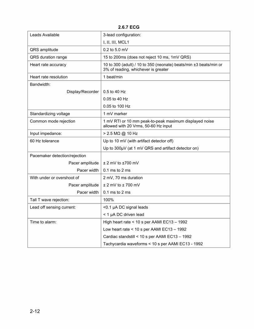
2.6.7 ECG
Leads Available 3-lead configuration:
I, II, III, MCL1
QRS amplitude 0.2 to 5.0 mV
QRS duration range 15 to 200ms (does not reject 10 ms, 1mV QRS)
Heart rate accuracy 10 to 300 (adult) / 10 to 350 (neonate) beats/min ±3 beats/min or 3% of reading, whichever is greater
Heart rate resolution 1 beat/min
Bandwidth:
Display/Recorder
0.5 to 40 Hz
0.05 to 40 Hz
0.05 to 100 Hz
Standardizing voltage 1 mV marker
Common mode rejection 1 mV RTI or 10 mm peak-to-peak maximum displayed noise allowed with 20 Vrms, 50-60 Hz input
Input impedance: > 2.5 MΩ @ 10 Hz
60 Hz tolerance Up to 10 mV (with artifact detector off)
Up to 300µV (at 1 mV QRS and artifact detector on)
Pacemaker detection/rejection
Pacer amplitude
Pacer width
± 2 mV to ±700 mV
0.1 ms to 2 ms
With under or overshoot of
Pacer amplitude
Pacer width
2 mV, 70 ms duration
± 2 mV to ± 700 mV
0.1 ms to 2 ms
Tall T wave rejection: 100%
Lead off sensing current: <0.1 µA DC signal leads
< 1 µA DC driven lead
Time to alarm: High heart rate < 10 s per AAMI EC13 – 1992
Low heart rate < 10 s per AAMI EC13 – 1992
Cardiac standstill < 10 s per AAMI EC13 – 1992
Tachycardia waveforms < 10 s per AAMI EC13 - 1992
2-12

3-1
SECTION 3. PRINCIPLES OF OPERATION
CONTENTS 3.1. Introduction............................................................................................... 3-3 3.2. Overall Principles Of Operation ................................................................ 3-3
3.2.1. Nellcor SPO2 ............................................................................................ 3-3 3.2.2. Cuff Blood Pressure (BP) and Pulse......................................................... 3-3 3.2.3. Alaris Oral and Rectal Thermometry......................................................... 3-4 3.2.4. ECG with Heart Rate and Respriation....................................................... 3-4 3.2.5. Host Communication Ports ....................................................................... 3-4
3.3. Functional Description .............................................................................. 3-5 3.3.1. PSU PWA ................................................................................................. 3-5 3.3.2. Mains Converter Module ........................................................................... 3-6 3.3.3. Main Board................................................................................................ 3-6 3.3.4. Keyboard PWA ......................................................................................... 3-7 3.3.5. ECG PWA................................................................................................. 3-8 3.3.6. Pneumatic Control .................................................................................... 3-8 3.3.7. LCD Assembly .......................................................................................... 3-9 3.3.8. Printer (Optional)..................................................................................... 3-10
LIST OF FIGURES 3-1 General System Diagram .......................................................................... 3-11/12

3-2
This page intentionally left blank.

3-3
SECTION 3. PRINCIPLES OF OPERATION
3.1 INTRODUCTION
This section provides overall theory of operation and functional description of the DINAMAP PRO 1000 (hereinafter referred to as PRO monitor). The PRO monitor has Blood Pressure (BP), Pulse, Temperature, SPO2, and ECG monitoring capability. The printer module is optional.
3.2 OVERALL PRINCIPLES OF OPERATION
The following paragraphs provide a general system interface relationship. The general block diagram is located in Figure 3-1. The PRO monitor is a portable unit that receives input power from an external AC source, external DC source, or internal rechargeable battery. When the ON/OFF button is pressed, the Main Board is brought out of a sleep mode and turns on the power regulators. The power regulators provide conditioned power from one of the input power sources: AC Mains, External DC, or the internal battery. The regulated power is routed to the Printed Wiring Assemblies (PWAs) via the cable harnesses. Once the PRO monitor is energized, a self-test is performed. The self-test automatically tests the main functions of the PRO monitor. Failure of the self-test will set the PRO monitor into a fail-safe mode with an audio alarm. Under normal operating condition, the PRO monitor is ready to monitor the patient vital signs using five external attachments: two temperature probes (rectal and oral), SPO2 sensor, ECG leads, and cuff. Interface with a central station or other device is accomplished through the 9-pin host communication port or 15-pin wireless communication port on the back of the PRO monitor.
3.2.1 Nellcor SPO2
When the SPO2 sensor is attached to the SPO2 connector and patient, it senses the heart rate and oxygen saturation. These analog signals are routed to the SPO2 PWA. The analog signals are analyzed on the SPO2 PWA. The results are digitized and sent to the Main Board via opto couplers. The couplers provide for patient isolation as well as serial data interface. The Main Board routes the data to the appropriate displays and/or printer. A reset signal to the SPO2 PWA is also provided for power up sequencing.
3.2.2 Cuff Blood Pressure (BP) and Pulse
When the cuff and hose are attached to the PRO monitor and Non-Invasive Blood Pressure (NIBP) determination is initiated, the pump inflates the cuff. Pressure transducers PT1 and PT2 monitor pressure information. The pneumatic manifold

3-4
has two valves, which are used to deflate the cuff. Valve control is through the Main Board. Determinations are made for the systolic BP, diastolic BP, pulse rate, and Mean Arterial Pressure (MAP). The results are displayed on the front panel Liquid Crystal Display (LCD). If an over-inflation condition occurs, it is detected by PT2, resulting in assertion of OVERPRESSURE. The OVERPRESSURE signal is routed to the PVM to release the air pressure. The Main Board also generates an alarm condition with the speaker sounding and a message in the LCD.
3.2.3 Alaris Oral and Rectal Thermometry
The PRO monitor has two temperature channels, one each for oral and rectal determinations. When a TEMPERATURE probe is attached to the temperature connector and patient, TEMP input is routed to the Main Board. This input represents the temperature to be measured. The Main Board converts the TEMP signal to a digital signal. During the conversion, the Main Board determines the patient temperature using a predictive or monitor mode algorithm depending on user setup. The patient temperature is distributed as a digital signal to the LCD display or printer. The PRO monitor has a probe check feature to help prevent erroneous temperature readings stemming from using the wrong probe for determinations (i.e. oral probe for rectal determination and vice versa.)
3.2.4 ECG with Heart Rate and Respiration The ECG parameter provides electrocardiographic waveform in a 3-electrode configuration. The 3-electrode configuration derives waveforms for leads I, II, or III . It includes a waveform cascade feature and can display one waveform as the primary lead. Breath rate is calculated by measuring the thoracic impedance between two electrodes. As the patient breathes, the movement of the chest changes the measured impedance to produce the respiration rate.
3.2.5 Host Communication Ports There are two Host Comm Ports provided on the back panel of the PRO monitor. The DB9 connector provides +5V(600mA Max), +12V(400mA Max), and two channels of TTL compatible communications. The DB15 connector provides +5V(600mA Max), +12V(250mA Max), Remote Alarm Signal, and a TLL/RS-232 selectable communication channel. Note: When the DB15 port is enabled, channel 2 of the DB9 port is disabled. The Host Comm Ports are used to interface the PRO monitor with other electronic devices (a central nurse’s station or remote alarm device.) Signals can be sent to the PRO monitor to initiate blood pressure determinations and other functions. Patient data can also be retrieved through this port. The DB9 connector should be used with Critikon Adapters ONLY. The host port signals on the DB15 connector are NON-ISOLATED and should be connected to equipment conforming to IEC
3-5
601-1-1 ONLY. Where isolation of data communication is required, the Critikon isolated level converter should be used. If external alarm control is required, Critikon part number 487208 (Isolated Remote Alarm Cable Assembly should ALWAYS be used. Please refer to the Information Sheet included with the isolated remote alarm cable for operational details. Note: When using remote alarm, the PRO monitor should be considered the primary alarm source. The secondary alarm is used for secondary purposes only.
3.3 FUNCTIONAL DESCRIPTION
The following paragraphs provide the functional interface relationship. The PRO monitor contains a number of electrical & electro-mechanical assemblies. These assemblies are:
• Power Supply Unit (PSU) PWA
• PSU Module
• Main Board
• Keyboard PWA
• ECG PWA
• Pneumatic control device
• Liquid Crystal Display (LCD) Assembly
• Printer PWA w/printer (optional)
3.3.1 PSU PWA The PSU supplies regulated DC power to PRO monitor. The PSU PWA is designed to operate from the output of the AC MAINS PSU module (+24VDC), EXTERNAL DC (+24VDC to +28VDC) source, or from an internal NiMH rechargeable battery (+12VDC). The PSU will automatically select the power source based on the following priority:
• Valid EXTERNAL DC input = +16VDC (If greater than or equal to output of Mains Converter)
• Valid AC MAINS input
• Valid NiMH battery The PSU PWA converts the selected power source into the following main voltages:
• VRAW1 (14.4VDC)
• VRAW2 (14.4VDC)
• VBAT The +12V printer supply voltage is down converted from VRAW1 and maintained by a boost regulator to +12V when VRAW1 falls under 12V. ANA+ is regulated to +14.4VDC from VRAW2 by a MAX668 step up controller. AUX +12V is down

3-6
converted from ANA+ using an LM340 regulator. ANA- is down converted from VRAW2 to –14.4VDC using a LM2594 step down regulator. VBAT is the battery voltage protected by a 500mA auto-reset fuse. It is also used to power the failsafe alarm circuits on the Main Board. The PSU PWA contains firmware that reports the charge status of the battery to the secondary processor on the main board. The secondary processor will charge the battery at the fastest rate allowable while keeping the PRO monitor power consumption under 60W. The fan control circuitry is located on the PSU PWA and is powered by VRAW1. The circuitry is thermally controlled and will start the fan when the thermistor (TH1) reaches approximately 50°C. The host communication port control circuitry selects whether channel 2 is routed to the Comms connector (DB-9) or the wireless connector (DB-15). If channel 2 is routed to the wireless connector, it can be configured for RS-232 or inverted TTL signals. Channel 1 is only available on the Comms connector as inverted TTL.
3.3.2 Mains Converter Module The Mains converter module is an AC Mains to DC converter. The module receives AC power from the mains input connector. When AC INPUT is applied to the module, the module AC/DC Converter changes the AC INPUT supply via rectifier circuit to a high voltage DC. The DC power is then routed through a high frequency switching converter and regulated to 24 VDC. This supply is connected to the PSU PWA for further regulation. The PSU only selects this source when DC Output is greater than +16VDC AND greater than the EXTERNAL DC input voltage.
3.3.3 Main Board The Main Board is configured with Flash ROM, EEPROM, RAM, 16-bit ADC, Primary Processor, Secondary Processor, SPO2 Module, and Temperature Module. The Primary Processor operates from a 4.9152 MHz crystal stepped up to 49.152 MHz. The Primary Processor services and controls the RAM, Flash ROM, EEPROM, the physiological interface modular devices and display backlighting. The Secondary Processor monitors the power supply circuit, controls the power-on/off sequences, performs watchdog task on itself and the Primary Processor, monitors signals within the NIBP module, and monitors board temperature. The Secondary Processor monitors the power supply circuit and controls the battery back up enable when no external sources are present and will shut down the unit when the battery is exhausted. It will enable the battery charging circuit based on the battery charge status, unit power consumption, and the availability of an external power source. The SPO2 processor monitors pulse oximetry signal and passes the processed signals to the SPO2 interface chip. The interface chip takes the signals and derives the oxygen saturation and heart rate data and converts them into serial data. The serial data from the SPO2 interface chip are send across an isolation barrier (optocouplers) and passed to the Primary Processor via a dual-channel UART.
3-7
The Temperature Module is a dual channel system. Two IVAC probes and the calibration resistor chain are connected into a multiplexer that is controlled by a single chip micro controller. The micro controller will then switch the output of the multiplexer between the calibration chain and the two probes. The multiplexer output is buffered, level shifted and amplified before being connected to a MAX1241 12 bit serial DAC, which is read by the microcontroller. The microcontroller will compute the resistance for each probe (and associated leads) and transmit both resistance values to the Primary Processor in a 34-bit data stream. A switch controls each probe; the Primary Processor will interpret the status of the switches, and select the appropriate part of the data stream from the temperature circuit. The Random Access Memory (RAM) is comprised of a SRAM chip and two SDRAM chips. The 512 Kbytes of battery-backed SRAM is provided to store trend data and to provide space for working algorithms and is accessed on bits D[0:15] of the data bus. The two 64 Mbit SDRAM chips are set up to form a 32 bit data bus on bits D[31:0] that is used for running the program and working memory. This gives 16Mbytes of memory with an access time of less that 20ns. The program is loaded (including the boot code) from the 16 bit FLASH Read Only Memory (ROM). The Electronically Erasable Programmable Read Only Memory (EEPROM) is an 8 bit chip that is used to store the calibration and other “setting” variables that have to be maintained in the event of a complete power failure. If a hardware or software error causes a malfunction, its watchdog will provide an internal and external RESET(L) signal. The FAILSAFE controller will cause the FAILSAFE(L) signal to go low. This signal passes to the Secondary Processor, which will disable the Primary Processor’s power supplies, thus turning it off. FAILSAFE(L) also passes to the PAL (NIBP control logic), which will dump the cuff pressure. The system is left in a safe state but is remains on to enable the Secondary Alarm to stay active. The Primary Processor monitors the activity of the secondary via its handshaking communications. If the Secondary fails, the Primary can assert the FAILSAFE line by overriding the FAILSAFE controller. The Secondary Alarm is a hardwired alarm that will sound in the event of a FAILSAFE condition. Pressing the OFF-key can immediately reset this alarm although it will eventually time-out after about 10 minutes.
3.3.4 ECG PWA The ECG PWA accepts signals from a 3-electrode cable for processing. The 3-electrode cable provides a single lead configuration with Lead I, Lead II , or Lead III available. The cables specified by Critikon are shielded and provide 1k-Ohm series (safety) resistors internal to the cable that are part of the current limiting defibrillator protection circuitry. Gas surge arrestors on the PWA provide lead-to lead defibrillator protection. In addition, a passive R/C network located on this PWA provides the first stage of high frequency filtering for EMC and ESU interference rejection. Two leads are selected for ECG measurement by a multiplexer (LS0, LS1 signal controlled) and passed to a differential amplifier. A second multiplexor selects the third electrode (the one not sent to the differential amplifier) and drives
3-8
the signal with an amplified and inverted version of the common mode voltage of the two measuring electrodes. This feedback action cancels most of the common mode signal applied to the differential amplifier. The output signal from the differential amplifier is then routed to bandpass filter and pacemaker detection circuit. The ECG PWA uses the pacemaker detection circuit to prevent pacemaker signals from interfering with heart rate measurements. The ECG signals are sent through a bandpass filter designed to pass pacemaker pulses in preference to ECG signals. The filter output is applied to a comparator that asserts an output signal when the input signal exceeds its positive or negative threshold. This output signal is used by the controller to blank the ECG signal channel and alert the host to the presence of a pacemaker pulse. The filtered ECG signal is routed to the A/D converter for transfer to the Main Board. The respiration circuit uses the ECG electrodes to measure respiration rate. This is achieved by applying an excitation current (61.5 kHz, well outside the bandwidth of normal ECG signals) generated by a square wave switch onto two selected electrodes. The measured voltage drop is filtered, the baseline component removed, and amplified. The analog voltage representing the impedance (resp value) is routed to A/D converter for transfer to the Main Board. The ECG PWA provides isolated power to its circuitry using an isolation transformer. A transformer driver drives the transformer primary at a frequency of about 350 kHz. The voltage of the transformer secondary is full-wave rectified using two Schottky barrier diodes. The isolated voltage is filtered by capacitors and regulated by a +5V regulator. Isolated ground is obtained from the center tap of the transformer. The data transferred from the A/D converter to the host is isolated using optocouplers.
3.3.5 Keyboard PWA The Keyboard PWA provides access to the basic functions of the PRO monitor. The buttons that control each function are integrated with its status LED to form a touch pad front panel. LEDs indicate the status of those functions by illuminating green when active and yellow when inactive. The exception is the “SILENCE” button, which is red when active. The function LEDs are driven by latches on the Main Board. The battery LED is continuously yellow when the unit is running on battery and flashes yellow when the battery is charging. The AC LED is green when an external power source is present. The keyboard is connected to the Main Board via a 36 way board-to-board connector.
3.3.6 Pneumatic Control The pneumatic functional block includes the control signal decode logic, the valve driver circuitry, the pump driver circuitry; pump current measurement circuit, and a safety interlock circuit. There are two transducers on board, PT1 and PT2. PT1 is used for main readings while PT2 confirms readings and is used to derive overpressure signals. The
3-9
following signals are multiplexed into a 16-bit SAR A/D converter via an 8:1 channel DG408:
• PT1A - the output of the measurement pressure sensor after amplification and filtering by means of a passive 1KHz low pass anti-alias filter.
• PT1B - the output of the measurement pressure sensor after amplification and filtering by means of a passive 20Hz low pass anti-alias filter.
• PT2 - the output of the confirmation/over-pressure sensor after amplification.
• TH REF - the voltage that the amplified PT2 has to attain before the safety circuit cuts in
• PT1 REF - the reference voltage that provides an offset voltage for the PT1 amplifier
• PT2 REF - the reference voltage that provides an offset voltage for the PT2 amplifier
• PUMPC - the pump current • VBAT- 1/11 ratio of VBAT voltage
The 16-bit value out of the ADC is available on the data bus at D[15:0]. Control signals for the board are derived via four different sources: direct control from outputs of the processor, controls signal derived from processor address write commands (which are stored in an addressable latch), signals derived from the watchdog timer, and signals generated by the overpressure functional block. The four valve control signals and the pump control signal are derived from the write address and stored in an addressable latch. Latch values are cleared by application of system RESET generated by the processor. Each latch signal is individually gated in a programmable logic device (16V8) with the fail safe input signal (watchdog timer) and the overpressure latch output to ensure pressure is removed from the patient cuff should either overpressure or processor failure condition occur. A cross-coupled latch for overpressure is included in the programmable logic device. It is set by the occurrence of an overpressure condition existing for a period greater than 500 milliseconds. When this condition occurs, Filter_OVP-0 transitions low setting the internal latch. The latch output state is indicated by the Latched_OVP signal. The latch can only be cleared by the PNEURESET input.
3.3.7 LCD Assembly The PRO monitor uses TFT (thin film transistor) active matrix color liquid display. The 10.4” diagonal display contains 640 x 480 pixels and can display 262,144 colors simultaneously. The display is backlit by cold-cathode fluorescent lamps. Note: the backlight power inverter is mounted separately from the other PCB’s. The LCD is driven from the Primary Processor via buffers (HCT244) on a dedicated LCD driver port:
3-10
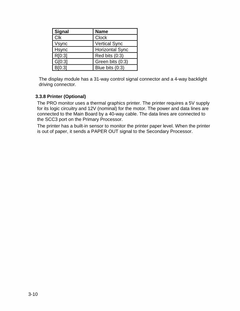
Signal Name Clk Clock Vsync Vertical Sync Hsync Horizontal Sync R[0:3] Red bits (0:3) G[0:3] Green bits (0:3) B[0:3] Blue bits (0:3)
The display module has a 31-way control signal connector and a 4-way backlight driving connector.
3.3.8 Printer (Optional) The PRO monitor uses a thermal graphics printer. The printer requires a 5V supply for its logic circuitry and 12V (nominal) for the motor. The power and data lines are connected to the Main Board by a 40-way cable. The data lines are connected to the SCC3 port on the Primary Processor. The printer has a built-in sensor to monitor the printer paper level. When the printer is out of paper, it sends a PAPER OUT signal to the Secondary Processor.

SECTION 4. GENERAL MAINTENANCE Contents 4.1. Introduction ......................................................................................................4-3 4.2. Configuring the PRO 1000 Monitor for the First Time ......................................4-3
4.2.1 Unpacking and Preparation for Installation..................................................4-3 4.2.2 Set the Date and the Clock .........................................................................4-5 4.2.3 Parameter Level Functional Testing............................................................4-6
4.3. Periodic Maintenance ......................................................................................4-7 4.3.1. As Required ...............................................................................................4-7
4.3.1.1 Integrity of Cuffs and Hoses ..................................................................4-7 4.3.1.2 External DC Supply and Battery ............................................................4-7 4.3.1.3 Cleaning of Accessories ........................................................................4-7 4.3.1.4 Long Term Storage................................................................................4-8
4.3.2 Annual Procedures......................................................................................4-8 4.4. Care of Storage Batteries ..............................................................................4-9 4.4.1. Procedures for First Use ............................................................................4-9 4.4.2 Battery Charging .........................................................................................4-9 4.5 Safety Resistance Testing ............................................................................. 4-12 4.6. Alarm Code Interpretation .......................................................................... 4-14
4.6.1. System Failures....................................................................................... 4-14 4.6.2. Hardware Errors ...................................................................................... 4-15 4.6.3. Parameter Failures.................................................................................. 4-15
4.6.3.1 ECG/RESP Errors .............................................................................. 4-15 4.6.3.2 NIBP Messages.................................................................................. 4-15 4.6.3.3 Temperature Messages...................................................................... 4-16 4.6.3.4 SpO2 Messages ................................................................................. 4-16
4.7. Service Mode Operation............................................................................. 4-16 4.7.1 SpO2 Tests .............................................................................................. 4-19 4.7.2 NIBP Tests ............................................................................................... 4-20
4.7.2.1 Leak Test............................................................................................ 4-21 4.7.2.2 NIBP Calibration Check ...................................................................... 4-23 4.7.2.3 Pressure Recalibration ....................................................................... 4-24 4.7.2.4 Overpressure Test.............................................................................. 4-25
4.7.3 ECG Tests................................................................................................ 4-27 4.7.4 Temp Tests .............................................................................................. 4-28 4.7.5 Recorder Tests......................................................................................... 4-30 4.7.6 Battery Tests ............................................................................................ 4-31 4.7.7 Test Failsafe Logic ................................................................................... 4-32 4.7.8 Keypad LED Test ..................................................................................... 4-33 4.7.9 Keypad Key Test ...................................................................................... 4-33 4.7.10 Sound Test ............................................................................................. 4-33 4.7.11 Turn off the System................................................................................ 4-33
4.8 Service Mode Exit .......................................................................................... 4-33 Appendix A - Test Record Appendix B – Monitor Configuration Log
4-1

This page intentionally left blank.
4-2

SECTION 4. GENERAL MAINTENANCE
4.1 INTRODUCTION This section contains general Monitor service procedures, including alarm code interpretation, service mode operation, and periodic maintenance and battery care. Refer to Section 5 for disassembly and reassembly procedures and related component service information. 4.2 Configuring the PRO 1000 Monitor for the First Time
4.2.1 Unpacking and Preparation for Installation
1. Unpack and identify the contents of all shipping materials. 2. Remove the PRO 1000 monitor. 3. Unpack the AC cord but do not plug the monitor in at this time. 4. Turn the monitor for access to the Host Comms Cover. 5. Use a Phillips-head screwdriver to remove the single screw that secures the
Host Comms cover. 6. The Battery fuse and the Fuse Holder are not connected at time of shipment.
Locate and remove the fuse and fuse holder from the protective plastic bag. 7. Identify the Battery Fuse holder located within the Host Comms well, near the
lower left side. 8. Insert the Battery Fuse into the Battery Fuse holder 9. Press the Battery Fuse Holder into the Battery Fuse mount using thumb
pressure until it is securely snapped in place. 10. Replace the Host Comms cover; refasten the Phillips screw. Tighten using
hand-tools only. 11. Plug the AC cord into the AC Mains input at the back of the monitor. 12. Plug the AC cord into a Hospital Grounded AC receptacle. A green LED will
illuminate on the front of the monitor indicating that an AC source is available. Prior to usage it is necessary to charge the monitor for 12 hours. This charge calibrates the battery charging circuitry with the charge status of the battery.
4-3

4-4
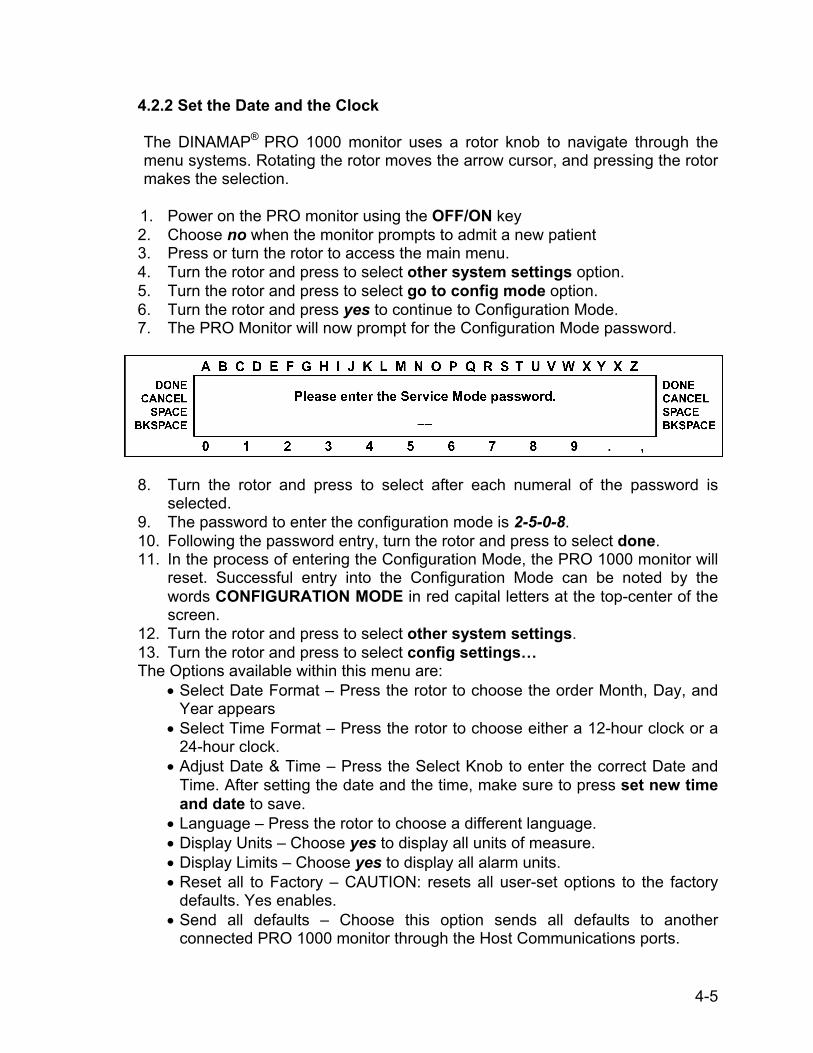
4.2.2 Set the Date and the Clock The DINAMAP® PRO 1000 monitor uses a rotor knob to navigate through the menu systems. Rotating the rotor moves the arrow cursor, and pressing the rotor makes the selection.
1. Power on the PRO monitor using the OFF/ON key 2. Choose no when the monitor prompts to admit a new patient 3. Press or turn the rotor to access the main menu. 4. Turn the rotor and press to select other system settings option. 5. Turn the rotor and press to select go to config mode option. 6. Turn the rotor and press yes to continue to Configuration Mode. 7. The PRO Monitor will now prompt for the Configuration Mode password.
8. Turn the rotor and press to select after each numeral of the password is selected.
9. The password to enter the configuration mode is 2-5-0-8. 10. Following the password entry, turn the rotor and press to select done. 11. In the process of entering the Configuration Mode, the PRO 1000 monitor will
reset. Successful entry into the Configuration Mode can be noted by the words CONFIGURATION MODE in red capital letters at the top-center of the screen.
12. Turn the rotor and press to select other system settings. 13. Turn the rotor and press to select config settings… The Options available within this menu are:
• Select Date Format – Press the rotor to choose the order Month, Day, and Year appears
• Select Time Format – Press the rotor to choose either a 12-hour clock or a 24-hour clock.
• Adjust Date & Time – Press the Select Knob to enter the correct Date and Time. After setting the date and the time, make sure to press set new time and date to save.
• Language – Press the rotor to choose a different language. • Display Units – Choose yes to display all units of measure. • Display Limits – Choose yes to display all alarm units. • Reset all to Factory – CAUTION: resets all user-set options to the factory
defaults. Yes enables. • Send all defaults – Choose this option sends all defaults to another
connected PRO 1000 monitor through the Host Communications ports.
4-5
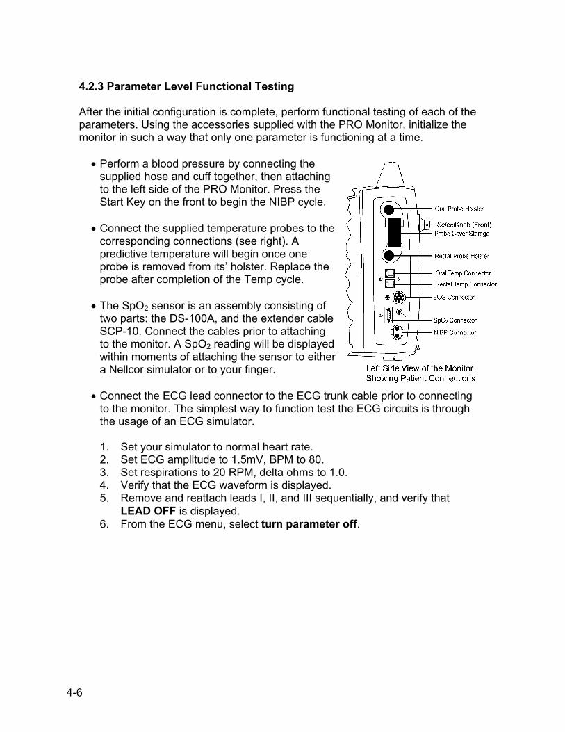
4.2.3 Parameter Level Functional Testing After the initial configuration is complete, perform functional testing of each of the parameters. Using the accessories supplied with the PRO Monitor, initialize the monitor in such a way that only one parameter is functioning at a time.
• Perform a blood pressure by connecting the supplied hose and cuff together, then attaching to the left side of the PRO Monitor. Press the Start Key on the front to begin the NIBP cycle.
• Connect the supplied temperature probes to the
corresponding connections (see right). A predictive temperature will begin once one probe is removed from its’ holster. Replace the probe after completion of the Temp cycle.
• The SpO2 sensor is an assembly consisting of
two parts: the DS-100A, and the extender cable SCP-10. Connect the cables prior to attaching to the monitor. A SpO2 reading will be displayed within moments of attaching the sensor to either a Nellcor simulator or to your finger.
• Connect the ECG lead connector to the ECG trunk cable prior to connecting
to the monitor. The simplest way to function test the ECG circuits is through the usage of an ECG simulator. 1. Set your simulator to normal heart rate. 2. Set ECG amplitude to 1.5mV, BPM to 80. 3. Set respirations to 20 RPM, delta ohms to 1.0. 4. Verify that the ECG waveform is displayed. 5. Remove and reattach leads I, II, and III sequentially, and verify that
LEAD OFF is displayed. 6. From the ECG menu, select turn parameter off.
4-6

4.3 PERIODIC MAINTENANCE
4.3.1 As Required Perform the following maintenance procedures as required.
4.3.1.1 Integrity of Hoses and Cuffs
When the pneumatic integrity of any NIBP cuff and hose is in doubt, replace the cuff and hose, and discard the questionable accessories.
4.3.1.2 Cleaning of Monitor
CAUTION: Do not clean Monitor with isopropyl alcohol or other
solvents.
Wipe the exterior of the Monitor with a cloth slightly dampened with mild detergent or normal hospital bactericides. Use dishwashing detergents such as IVORY and JOY (registered trademarks of Procter & Gamble Corp.), or PALMOLIVE (registered trademark of Colgate-Palmolive Corp.)
Do not immerse unit.
4.3.1.3 Cleaning of Accessories
Clean the adult cuffs supplied for use with the monitor by hand washing in warm, soapy water. However, take care to avoid entry of water into the cuff and hoses at any time. If water enters the cuff, dry the cuff by passing air through it. The neonatal cuffs are for single patient use - discard if they become soiled. Clean cuffs and hoses with a cloth slightly dampened with mild detergent. Do not immerse hoses. Do not immerse cuffs without prior application of cuff hose caps. Clean SpO2 sensor surface before and after each patient use. Clean SpO2 sensor with a cloth slightly dampened with a mild detergent. Wipe SpO2 sensor to ensure all detergent residue has been removed. Follow manufacturer's instructions for cleaning ECG lead wires and cable. Compatible cleaning and disinfecting solutions are:
4-7

Dishwashing detergents such as IVORY and JOY (registered trademarks of Procter & Gamble Corp.), or PALMOLIVE (registered trademark of Colgate-Palmolive Corp.) Chlorine bleach disinfectant, 5.25%, 0.75 cup per gallon of water
CAUTION: Do not apply isopropyl alcohol to the Monitor - some parts can become marred and cracked.
Isopropyl alcohol (for accessories only) Cidex Formula 7 (registered trademark of Johnson & Johnson Medical Products, Inc.) or pHisoHex (registered trademark of Winthrop-Breon Laboratories) Quaternary-based germicidal detergents like VESTAL INSURANCE (registered trademark of the Vestal Corp.), HI-TOR PLUS (registered trademark of the Huntington Corp.), or VIREX (registered trademark of S.C. Johnson & Son Corp.) For the above, follow manufacturers' recommendations for dilution rate and use. These recommendations are not an endorsement of the manufacturers or of the effectiveness of these materials for cleaning or disinfecting.
4.3.1.4 Long-Term Storage
If it becomes necessary to store the Monitor for an extended period of time, remove all attached accessories. Attach the original packing inserts, and place the monitor into the original shipping container. Generally, long-term storage of a nickel-metal hydride battery in either a charged or discharged condition has no permanent effect on capacity. Capacity loss due to self-discharge is reversible, and nickel-metal hydride batteries can recover to full capacity by proper recharging. For example, cycling through repeated charge/discharge cycles can restore a full capacity of a nickel-metal hydride battery that was stored at room temperature for up to one year. Long-term storage at high temperatures can lead to deterioration of seals and separators and should be avoided.
4.3.2 Annual Procedures Perform the test procedures described in paragraph 4.7 every twelve months, or whenever the accuracy of any reading is in doubt.
4-8

Note: An internal, 3.6V NiMh battery acts as an alarm backup and maintains the nonvolatile RAM memory when the Monitor is off or away from AC mains. A system alarm message will be generated if backup battery replacement is required.
4.4 CARE OF STORAGE BATTERIES The Monitor uses one nickel-metal-hydride (NiMH) storage battery. The battery can be charged at any time without reducing the charging capacity.
4.4.1 Procedures For First Use Follow these procedures to condition a new NiMH battery and optimize its performance: The internal battery will automatically charge when the AC power supply is in use. When the battery is charged for the first time, the charger may indicate prematurely that charging is incomplete. This is normal and can happen with all rechargeable batteries when first charged.
4.4.2 Battery Charging
The Monitor charges the NiMH battery whenever the AC power supply is in use. The Monitor automatically senses if the battery needs recharging. Battery charging will continue as long as the Monitor is connected to the AC power supply, even when the Monitor is turned off.
• Batteries should be charged before first use or after prolonged periods of
storage.
• The battery should be charged before use, as a charged battery loses some charge when left in storage.
• The battery should be charged at room temperature (59° F - 86° F; 16° C -
30° C).
• It is normal for the battery to become warm during charging or after use.
• Batteries can be charged or topped-off at any time. It is not necessary to wait until they are fully discharged.
• If the monitor is idle for extended periods, it should be fully charged once a
month to ensure optimum performance.
4-9

Table 4-1. Battery Alarms
Alarm Type Indication Probable Cause BATT WRONG TYPE - REMOVE or INTERNAL BATT - WRONG TYPE -REMOVE
Message appears in alarm message field Unapproved battery engaged
BATT CHECKING or INTERNAL BATT - CHECKING
Message appears in alarm message field
Noncommunicating battery engaged
INTERNAL BATT FAIL - REPLACE NOW
Message appears in alarm message field
Internal battery loses voltage or communication or is not accepting proper charge
< 00:30 BATTERY Message appears in alarm message field and in SelectBox
30 minutes remaining in battery life
< 00:10 BATTERY Message appears in alarm message field 10 minutes remaining in battery life
SHUTTING DOWN Message appears in alarm message field
< 1 minute remaining in battery life. Monitor may shut down anytime after 45-60 seconds
AC FAIL - < 00:30 BATTERY
Message appears in alarm message field and procedural alarm sounds
Upon loss of AC power, the internal battery is engaged with less than 30 minutes of life (but more than 10 minutes) remaining
CHECK COOLING FAN Message appears in the alarm message field
Monitor's internal temperature is too high. Cooling fan may be blocked or inoperative
AC FAIL - < 00:10 BATTERY
Message appears in alarm message field and crisis alarm sounds
Upon loss of AC power, the internal battery is engaged with less than 10 minutes of life remaining
4-10
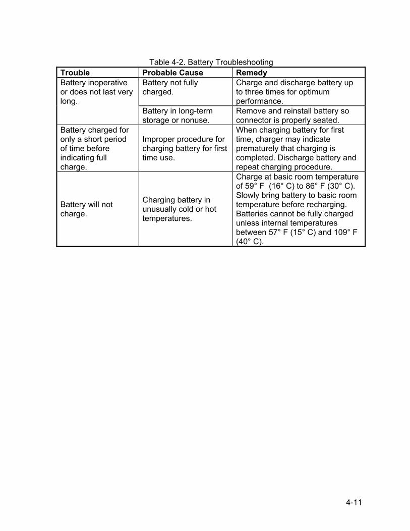
Table 4-2. Battery Troubleshooting
Trouble Probable Cause Remedy Battery inoperative or does not last very long.
Battery not fully charged.
Charge and discharge battery up to three times for optimum performance.
Battery in long-term storage or nonuse.
Remove and reinstall battery so connector is properly seated.
Battery charged for only a short period of time before indicating full charge.
Improper procedure for charging battery for first time use.
When charging battery for first time, charger may indicate prematurely that charging is completed. Discharge battery and repeat charging procedure.
Battery will not charge.
Charging battery in unusually cold or hot temperatures.
Charge at basic room temperature of 59° F (16° C) to 86° F (30° C). Slowly bring battery to basic room temperature before recharging. Batteries cannot be fully charged unless internal temperatures between 57° F (15° C) and 109° F (40° C).
4-11

4.5 SAFETY RESISTANCE TESTING
Using a safety analyzer (Dynatech Nevada Model 235A or equivalent), check the ground resistance of the PRO 1000 Monitor; refer to the Rear View graphic for locations of test points. Earth-To-Secondary Continuity Verify that the resistance between the AC Mains ground pole and the External DC connector ground is less than or equal to 1Ω. AC Mains Leakage – Normal Polarity For the following tests, 260 VAC is applied at the Monitor’s AC Mains input in normal polarity.
No Fault Verify that the leakage from the Line pole to the Ground pole is less than or equal to 500 µA. Open Ground Disconnect the Monitor’s ground lead from earth ground (for the duration of this test only) and verify that the leakage from the Line pole to the Ground pole is less than or equal to 500 µA. Open Neutral Open the Monitor’s neutral lead (for this test only) and verify that the leakage from the Line pole to the Neutral pole is less than or equal to 500 µA.
AC Mains Leakage – Reverse Polarity For the following tests, 260 VAC is applied at the Monitor’s AC Mains input in reverse polarity (inputs to Line pole and Neutral pole reversed).
No Fault Verify that the leakage from the Line pole to the Ground pole is less than or equal to 500 µA. Open Ground Disconnect the Monitor’s ground lead from earth ground (for the duration of this test only) and verify that the leakage from the Line pole to the Ground pole is less than or equal to 500 µA. Open Neutral Open the Monitor’s Neutral lead (for the duration of this test only) and verify that the leakage from the Line pole to the Neutral pole is less than or equal to 500 µA.
4-12

Rear View of Monitor with safety connection exposed
4-13

4.6 ALARM CODE INTERPRETATION Refer to Table 4-1 for information about procedural alarms that involve battery operation. If any other alarms appear that are not listed in the paragraphs that follow, record the error message and report the failure to Customer Support. Refer to the Operation Manual for information about patient alarms and general procedural alarms.
4.6.1 System Failures When a system failure is encountered, the error code is displayed on the screen for five seconds and the system enters failsafe mode. The error code is logged in the history log. General system error codes are listed below. If any other SY or similar code appears, report it to Customer Support.
Error Code Explanation Possible Cause(s)
SY-16 Power fail signal true time is too long
Circuit that drives POWERFAIL* signal is defective
SY-19 Software detected power supply out of limits
1. Go to service mode to observe current values for power supplies
2. Digital to analog converter is defective
SY-20 Checksum of code in flash memory is not valid
1. Defective flash memory chip. 2. Error during programming of flash memory.
SY-43 Real time clock running too slow
1. RTC chip running too slow or not at all. 2. System clock running too fast.
SY-44 Real time clock funning too fast
1. Noise getting into RTC chip crystal input. 2. Defective or wrong crystal on clock chip. 3. System clock running too slow.
4-14
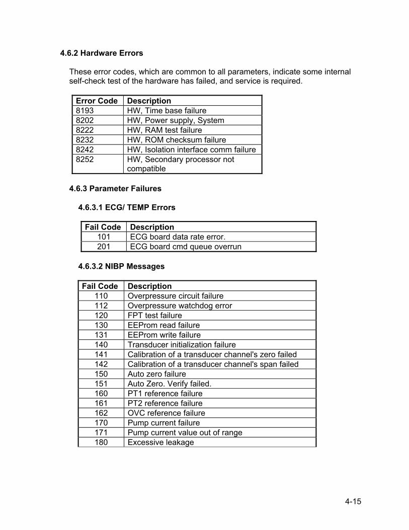
4.6.2 Hardware Errors These error codes, which are common to all parameters, indicate some internal self-check test of the hardware has failed, and service is required.
Error Code Description 8193 HW, Time base failure 8202 HW, Power supply, System 8222 HW, RAM test failure 8232 HW, ROM checksum failure 8242 HW, Isolation interface comm failure 8252 HW, Secondary processor not
compatible
4.6.3 Parameter Failures
4.6.3.1 ECG/ TEMP Errors
Fail Code Description 101 ECG board data rate error. 201 ECG board cmd queue overrun
4.6.3.2 NIBP Messages Fail Code Description
110 Overpressure circuit failure 112 Overpressure watchdog error 120 FPT test failure 130 EEProm read failure 131 EEProm write failure 140 Transducer initialization failure 141 Calibration of a transducer channel's zero failed 142 Calibration of a transducer channel's span failed 150 Auto zero failure 151 Auto Zero. Verify failed. 160 PT1 reference failure 161 PT2 reference failure 162 OVC reference failure 170 Pump current failure 171 Pump current value out of range 180 Excessive leakage
4-15
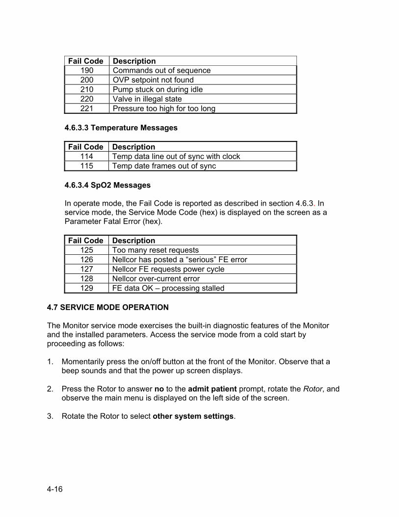
Fail Code Description
190 Commands out of sequence 200 OVP setpoint not found 210 Pump stuck on during idle 220 Valve in illegal state 221 Pressure too high for too long
4.6.3.3 Temperature Messages
Fail Code Description
114 Temp data line out of sync with clock 115 Temp date frames out of sync
4.6.3.4 SpO2 Messages
In operate mode, the Fail Code is reported as described in section 4.6.3. In service mode, the Service Mode Code (hex) is displayed on the screen as a Parameter Fatal Error (hex).
Fail Code Description
125 Too many reset requests 126 Nellcor has posted a “serious” FE error 127 Nellcor FE requests power cycle 128 Nellcor over-current error 129 FE data OK – processing stalled
4.7 SERVICE MODE OPERATION The Monitor service mode exercises the built-in diagnostic features of the Monitor and the installed parameters. Access the service mode from a cold start by proceeding as follows: 1. Momentarily press the on/off button at the front of the Monitor. Observe that a
beep sounds and that the power up screen displays.
2. Press the Rotor to answer no to the admit patient prompt, rotate the Rotor, and observe the main menu is displayed on the left side of the screen.
3. Rotate the Rotor to select other system settings.
4-16

Select go to service mode. Rotate and press the knob again to answer yes at the prompt. Note that the menu changes to what is shown below.
4. Observe that a row of numbers is displayed at the bottom of the screen. Turn
the rotor and press to select after each numeral is selected. 5. The password to enter service mode is: 2213. Following completion of the
password entry, turn the rotor and press to select DONE. 6. In the process of entering the Service Mode, the PRO 1000 Monitor will reset.
Successful Entry into Service Mode can be noted by the Service Menu title display on the upper left side of the display.
NOTE: The service mode can also be entered directly from a cold start by pressing and holding the following three keys until full power-up: OFF/ON, AUTO-BP, ands GO/STOP. To make any changes to the Service Menu, the password will still have to be entered: press the rotor to enter service password. 7. At this point the Service Mode main screen should be present in the main
display, as shown below. The service menu service parameters area displays a list that corresponds to the number and type of parameters that have been detected by the Monitor. If the service mode was entered directly (as described in the NOTE above), enter service password appears above the service parameters on the service menu. If recalibration of any component is required, the password MUST be entered (as described in steps 5 and 6) before any changes to calibration can be made.
4-17
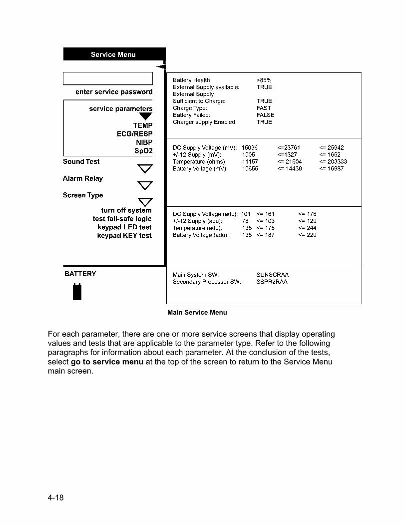
Main Service Menu
For each parameter, there are one or more service screens that display operating values and tests that are applicable to the parameter type. Refer to the following paragraphs for information about each parameter. At the conclusion of the tests, select go to service menu at the top of the screen to return to the Service Menu main screen.
4-18

4.7.1 SpO2 Tests
1. Disconnect all sensor cables from the SpO2 Parameter, and ensure that the SpO2 parameter is listed within the main Service menu.
2. From the Service Menu, Turn and press the rotor to select the SpO2 service
parameter. The SpO2 service menu should appear, with the SpO2 STATUS displaying SENSOR Disconnected and the SPO2 MESSAGES display empty. Example shown below.
SpO2 Service Menu
3. Insert the Nellcor SRC-2 pocket tester into the Parameter front panel SpO2
sensor socket (use the extender cable SCP-10), and press until fully seated in the socket.
4-19
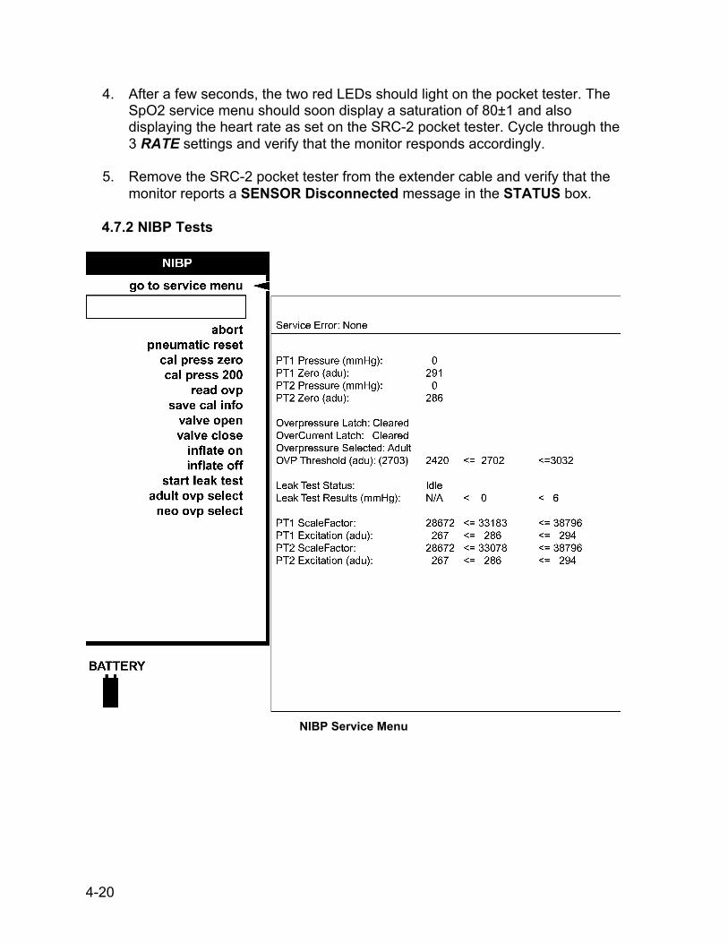
4. After a few seconds, the two red LEDs should light on the pocket tester. The SpO2 service menu should soon display a saturation of 80±1 and also displaying the heart rate as set on the SRC-2 pocket tester. Cycle through the 3 RATE settings and verify that the monitor responds accordingly.
5. Remove the SRC-2 pocket tester from the extender cable and verify that the monitor reports a SENSOR Disconnected message in the STATUS box.
4.7.2 NIBP Tests
NIBP Service Menu
4-20

Perform the following tests to determine that the NIBP parameter is functioning normally.
4.7.2.1 Leak Test 1. Using the calibration kit (part number 320-246), an adult cuff and air hose,
and a manometer, set up the equipment as shown in Figure 3-1. Connect the hose to the NIBP Parameter. Make sure all fittings are tight, and that the valve on the manual inflation bulb is fully closed.
Figure 4-1. NIBP Test Setup
2. From the Service Menu, Turn and press the rotor to select the NIBP service
parameter.
3. Turn and press the rotor to select pneumatic reset. 4. Turn and press the rotor to select valve close.
4-21

5. Turn and press the rotor to select start leak test. Observe that the Leak
Test Status message on the menu indicates Busy.
6. Observe that the pump begins inflating the system to 200 ~ 210 mmHg, at which point the pump operation will cease. The Monitor will begin to calculate system pressure loss rate.
7. After about 60 seconds, the pressure is released, and the menu should
display Leak Test Status Passed, and the Leak Test Results indication should be a value less than 6. Service Error: None should continue to display.
8. If the menu displays Leak Test Failed, continue to step 9.
9. Using the calibration kit (part number 320-246), an adult cuff and air hose,
and a manometer, set up the equipment as shown in Figure 4-2.
Figure 4-2 Leak Test Setup
10. Close the pressure release valve on the manometer inflation bulb and
slowly increase the pressure to 200-mmHg ±1 mmHg.
4-22

11. Verify the pressure indicated on the manometer remains within 5 mmHg of 200 mmHg for 60 seconds. If not, either the cuff or hose or both may be defective. If the cuff and hose pass this test, repeat steps 1 through 7 to try to isolate the leak. Repeat the leak test for all cuff and hose combinations to be used with the Monitor.
4.7.2.2 NIBP Calibration Check
1. Using the calibration kit (part number 320-246), an adult cuff and air hose, and a manometer, set up the equipment as shown in Figure 4-1. Connect the hose to the NIBP Parameter. Make sure all fittings are tight, and that the inflation bulb valve is closed tightly.
2. From the Service Menu, Turn and press the rotor to select the NIBP service parameter.
3. Turn and press the rotor to select pneumatic reset.
4. Turn and press the rotor to select
valve close. 5. Observe that both PT1 Pressure
and PT2 Pressure equal initial values of zero mmHg (0 mmHg).
6. Connect the pneumatic hose to the Monitor’s NIBP port.
7. Fold the adult cuff so the index line is aligned with the inner range mark on the inside of the cuff. Make sure all fittings are tight, and that the valve on the inflation bulb is closed tightly. If there is doubt about the integrity of the system, perform the leak test (paragraph 4.7.2.1) before continuing.
8. Close the pressure release valve on the manometer inflation bulb and manually pump up the pressure until the manometer indicates approximately 220 mmHg.
4-23

9. Allow the pressure to stabilize for at least a minute. Then open the pressure release valve on the manometer inflation bulb and carefully bleed off pressure until the manometer indicates 200 mmHg.
10. Observe that the values of PT1 Pressure and PT2 Pressure on the menu indicate within 1 mmHg of the pressure shown on the manometer.
11. Verify the system linearity by repeating steps 8 & 9 using manometer readings of 250 mmHg, 150 mmHg, and 50 mmHg. Observe that the PT1 and PT2 Pressures are within 3 mmHg of manometer readings for each of these pressure indications.
4.7.2.3 Pressure Recalibration
1. Always enter Service Mode with the password, as described in paragraph
4.7, before attempting to recalibrate equipment.
2. Using the calibration kit (part number 320-246), an adult cuff and air hose, and a manometer, set up the equipment as shown in Figure 4-2. Do not connect the pneumatic hose to the NIBP port yet.
3. From the Service Menu, Turn and press the rotor to select the NIBP service parameter.
4. Turn and press the rotor to select pneumatic reset.
5. Turn and press the rotor to select valve close.
7. Observe that both PT1 Pressure and PT2 Pressure display initial values of 0 on the menu.
8. Turn and press the rotor to select cal press zero. Observe that the message Inflate System to 200 mmHg Then Hit ‘Cal Press 200’ is displayed on menu.
9. Connect hose to NIBP Parameter.
4-24

10. Fold the adult cuff so the index line is aligned with the inner range mark on
the inside of the cuff. Make sure all fittings are tight, and that valve on inflation bulb is closed tightly. If there is doubt about the integrity of the system, perform the leak test (paragraph 4.7.2.1) before continuing.
11. Close the pressure release valve on the manometer inflation bulb and manually pump up the pressure until the manometer indicates approximately 220 mmHg.
12. Allow the pressure to stabilize for at least a minute. Then open the pressure release valve on the manometer inflation bulb and carefully bleed off pressure until the manometer indicates a little more than 200 mmHg.
13. Turn and press the rotor to select cal press 200, but do not press the knob
at first. 14. When the manometer indicates exactly 200 mmHg, press the Rotor.
Observe that system pressure is released, and the message: !!!!! CAL INFO NOT SAVED!!!!! is displayed on menu.
15. Turn and press the rotor to select save cal info. If the system is operating normally, the menu displays Service Error: None, and the calibration setting is saved.
16. Repeat the calibration check procedure (paragraph 4.7.2.2) to confirm the
calibration setting.
4.7.2.4 Overpressure Tests
1. Using the calibration kit (part number 320-246), an adult cuff and air hose, and a manometer, set up the equipment as shown in Figure 4-1. Connect the hose to the NIBP Parameter. Make sure all fittings are tight, and that valve on inflation bulb is closed tightly.
2. From the Service Menu, Turn and press the rotor to select the NIBP service parameter.
3. Turn and press the rotor to select pneumatic reset.
4-25

4. Turn and press the rotor to select valve close. 5. Observe that the menu displays Overpressure Selected Adult. If not, turn
and press the rotor to select adult ovp select. 6. Turn and press the rotor to select inflate on. The pump should begin to
inflate the system. 7. Watch the pressure indication increase on the manometer, and observe
that the pump is shut down and the pressure is released when the manometer indicates in the range of 300 to 330 mmHg. Observe that the menu displays Service Error: None.
8. Turn and press the rotor to select pneumatic reset. 9. Turn and press the rotor to select valve close. 10. Turn and press the rotor to select neo ovp select. Observe that the menu
displays Overpressure Selected Neo. 11. Turn and press the rotor to select inflate on. The pump should begin to
inflate the system. 12. Watch the pressure indication increase on the manometer, and observe
that the pump is shut down and the pressure is released when the manometer indicates in the range of 150 to 165 mmHg. Observe that the menu displays Service Error: None.
13. If the overpressure test results in an “out of tolerance” condition, contact
Critikon Technical Support at 877-274-8456 for assistance.
4-26
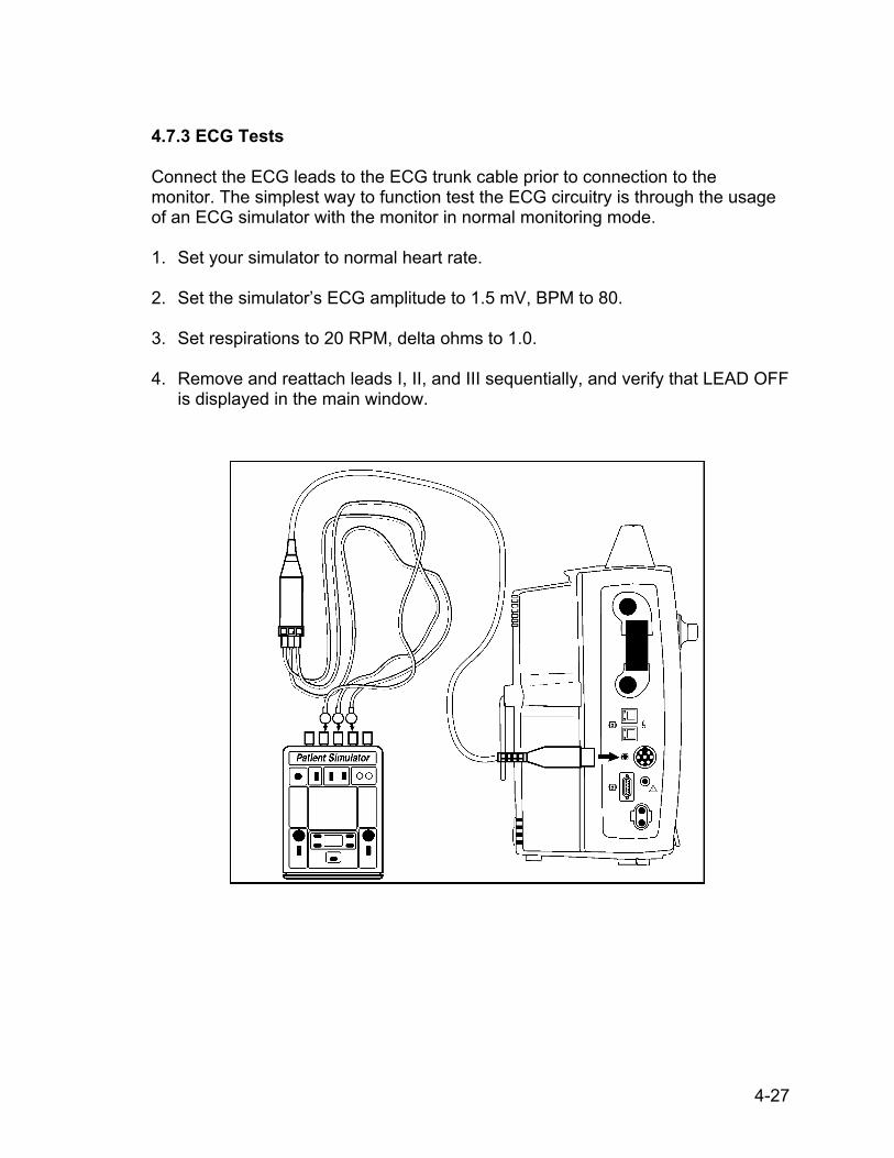
4.7.3 ECG Tests Connect the ECG leads to the ECG trunk cable prior to connection to the monitor. The simplest way to function test the ECG circuitry is through the usage of an ECG simulator with the monitor in normal monitoring mode. 1. Set your simulator to normal heart rate.
2. Set the simulator’s ECG amplitude to 1.5 mV, BPM to 80.
3. Set respirations to 20 RPM, delta ohms to 1.0.
4. Remove and reattach leads I, II, and III sequentially, and verify that LEAD OFF
is displayed in the main window.
4-27
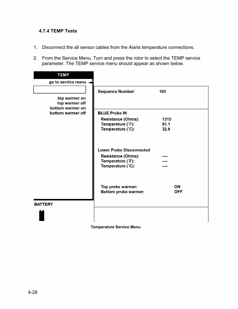
4.7.4 TEMP Tests
1. Disconnect the all sensor cables from the Alaris temperature connections.
2. From the Service Menu, Turn and press the rotor to select the TEMP service
parameter. The TEMP service menu should appear as shown below.
Temperature Service Menu
4-28
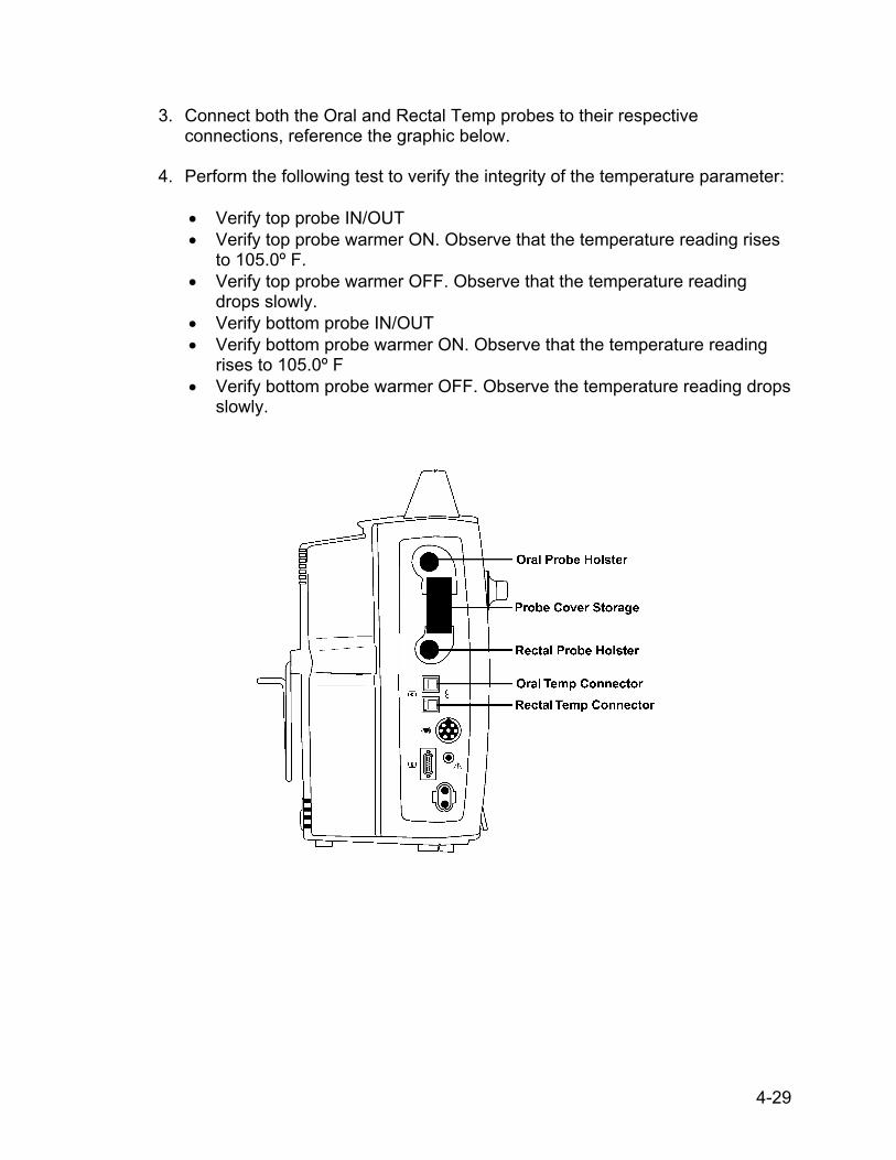
3. Connect both the Oral and Rectal Temp probes to their respective connections, reference the graphic below.
4. Perform the following test to verify the integrity of the temperature parameter:
• Verify top probe IN/OUT • Verify top probe warmer ON. Observe that the temperature reading rises
to 105.0º F. • Verify top probe warmer OFF. Observe that the temperature reading
drops slowly. • Verify bottom probe IN/OUT • Verify bottom probe warmer ON. Observe that the temperature reading
rises to 105.0º F • Verify bottom probe warmer OFF. Observe the temperature reading drops
slowly.
4-29

4.7.5 RECORDER tests (if fitted)
1. Ensure that paper has been loaded into the
Recorder Parameter, and you are presently in the Service Mode.
2. From the Service Menu, Turn and press the rotor to
select the RECORDER test option. Turn and press the rotor to choose the 3 waveforms option. Verify that all printouts are of even tone and all pixels are present.
3. Select the 6.25mm/S option.
4. Allow for the paper to spool out a 12 inch printed
section. 5. Select Vertical Text test. Verify that the printed text
is legible and evenly spaced.
6. Select Horizontal Text test. Verify that the printed text is legible and evenly spaced.
Horizontal Text Sample 6.25 mm/sec – 1 waveform chosen print test
4-30

4.7.6 Battery Tests
From within the Service Menu, battery status information is displayed on the right upper 1/4th of the display.
Battery/ Power Supply menu
1. Battery Health: the Monitor’s software approximates the true status of the
battery’s health. The value indicated is displayed as both a number (in percentage) and as an icon on the bottom-left area of the display.
2. External Supply available: True indicates a source other than the internal
battery is providing power for the monitor, and a source to charge the internal battery.
3. External Supply Sufficient to Charge: If the voltage from the external supply
is greater than that of the internal battery, the monitor will display the results as TRUE. False will result if either the voltage is equal to or lower than the power available from the internal battery.
4. Charge Type: Fast or Slow.
5. Battery Failed: Any result other than FALSE, indicates that the internal
battery has suffered a failure and should be investigated.
4-31
6. Charger Supply Enabled: Should always be TRUE as the monitor consistently attempts to keep the battery at its’ fullest capacity. A FALSE indicates the battery may be faulty or not installed, or the charge circuit may have failed. Also, if no external source of power is available, the monitor will register a FALSE result.
4.7.7 Test Failsafe Logic
1. From the Service Menu, turn the rotor to select test fail-safe logic. A dialogue
box will appear: 2. CAUTION! This will cause the system to freeze for approx. 2 seconds then enter fail-safe mode. Continue?
Answer yes.
2. After two seconds, the system will freeze and an alarm will sound. Recycle the system power using the on/off button. To return to the Service Mode, repeat the procedures as described in section 4.7.
4-32

4.7.8 Keypad LED Test
1. From the Service Menu, rotate and press the rotor to select keypad LED test. Observe that each of the keys on the PRO 1000 monitor-face, illuminate one key at a time. With the exception of the ON/OFF key, observe whether any of the keys fail to illuminate.
2. After all keys have been tested, press the rotor again to stop the test.
4.7.9 Keypad KEY Test Verify that the keypad LEDs are illuminated (except Main, Trend, and Standby)
4.7.10 Sound Test
Verify that the Monitor produces tones of various pitches when this option is selected.
4.7.11 Turn off system Selection of this menu item will bring up a dialogue window requesting you to confirm your decision: CAUTION! This will turn the system off. Are you sure you want to do this? Selecting yes will power off the monitor; no will return you to the Service Menu.
4.8 SERVICE MODE EXIT To exit the service mode and power off the Monitor, locate and press the key marked ON/OFF at the front of the Monitor.
4-33

This page intentionally left blank.
4-34

TEST RECORD (Appendix A) Model# Serial# . Step Description Min Max Actual Pass Fail N/A SpO2 Tests 4.7.1 Verify Pleth waveform
4.7.1 SpO2 reading at 100% Saturation 96 100
4.7.1 SpO2 reading at 90% Saturation 86 94 Internal Tests (Perform in Service Mode) 4.7.2.1 Leakage Test 4.7.2.2 UUT Pressure - 50 mmHg 46 54 4.7.2.2 UUT Pressure - 150 mmHg 145 155 4.7.2.2 UUT Pressure - 250 mmHg 244 255 4.7.2.4 Verify adult overpressure occurs between 300~350 mmHg 4.7.2.4 Verify neo overpressure occurs between 150~165 mmHg 4.7.4 Verify top probe IN/OUT 4.7.4 Verify top probe warmer ON 4.7.4 Verify top probe warmer OFF 4.7.4 Verify bottom probe IN/OUT 4.7.4 Verify bottom probe warmer ON 4.7.4 Verify bottom probe warmer OFF 4.7.5 Recorder Test 4.7.8 Keypad Test 4.7.10 Speaker Test ECG Tests (Perform in Monitor Mode) 4.7.3 Verify Waveform 4.7.3 Verify BPM (@ 80 BPM) 76 84 4.7.3 Verify Paced Signal 4.7.3 Verify Lead-Off RESP Tests (Perform in Monitor Mode) Verify Waveform Verify RESP (@ 20 RPM) 17 23 Verify RESP (@ 5 RPM) 2 8 Verify alarm sounds & displays below 6 RPM BPM Tests (Perform in Monitor Mode) Verify low rate alarm at 45 BPM
Heart Rate reading at 50 BPM (SpO2) 46 54
Heart Rate reading at 120 BPM (SpO2) 116 124
Heart Rate reading at 80 BPM (SpO2) 76 84 NIBP Tests (Function test in Monitor Mode) Initial cuff inflation (Adult cuff) 161 195 Heart Rate reading @ 80 BPM (NIBP) 76 84 Inflate/ Deflate cycle time <120 seconds Initial cuff inflation (Neonatal cuff) 94 151
4-35

Appendix A (continued) Temperature Test (service or monitor mode - requires Alaris Temp Simulator) Measured top Temp in ºF (98.6º nominal) 98.4 98.8 Measured top Temp in ºF (80.2º nominal) 79.9 80.5 Measured top Temp in ºF (107.8º nominal) 107.5 108.1 Measured bottom Temp in ºF (107.8º nominal) 107.5 108.1 Measured bottom Temp in ºF (80.2º nominal) 79.9 80.5 Measured bottom Temp in ºF (98.6º nominal) 98.4 98.8 Front Panel Key Tests (Perform in Service Mode) 4.7.9 Verify appropriate responses to keypresses Battery System Test (Perform in Monitor Mode) Verify AC Mains indicator Remove AC, Verify uninterrupted battery operation Verify Battery LED is lit Safety Testing External DC to GND Resistance (m) 0 1000 SpO2 leakage (µA) 0 150 Temp Leakage (µA) 0 50 d ECG Leakage (µA) 0 50 Normal no-fault leakage (µA) 0 500 Normal open-ground leakage (µA) 0 500 Normal open-neutral leakage (µA) 0 500 Reverse no-fault leakage (µA) 0 500 Reverse open-ground leakage (µA) 0 500 Reverse open-neutral leakage (µA) 0 500
Tested by:
Date:
Signature: Facility:
4-36

Date: City:
Hospital:
How to Enter Configuration Mode1. Choose other system settings from the Main Menu.2. Choose go to config mode. The message This will initiate the sequence for entering Configuration Mode. Do you want to do this? appears.3. Choose Yes to enter configuration mode.4. The message Please enter the Config Mode password appears. Enter the password. FACTORY SET CONFIG PASSWORD: 25085. Choose Done.6. The system will restart in configuration mode. Press the SelectKnob to access the Configuration Menu.
How to Configure Default Tables1. Choose admit patient from the Configuration Menu.2. Choose Choose patient settings. Select the table you wish to configure (default 1 through default 6).3. A popup window appears: All unsaved changes to the current default will be lost! Are you sure you want to do this? Choose Yes.4. Choose Patient type and select either Adult, pediatric, or neonate.5. Change all other available settings as desired.6. To save your changes for the selected table go to other system settings, choose save default changes.7. A popup window appears: Enter the name for this default. Rename or accept the default table and choose DONE. Your data will be saved.8. Repeat steps 1 through 7 for configuring the remaining five default tables.
How to Exit Configuration Mode1. Choose other system settings from the Configuration Menu.2. Choose exit config mode.3. A popup window appears: This will exit configuration mode. All unsaved changes will be lost. Are you sure you want to do this? Choose Yes.4. The system will automatically restart in patient monitoring mode.
Warning: All monitoring will cease when entering configuration mode. Do not enter this mode if actively monitoring a patient.
Serial Numbers:
MONITOR CONFIGURATION LOG - Appendix BDINAMAP PRO 1000 Monitor Series
Note: Please refer to the PRO 1000 Pre-Service and Calibration Procedures for instructions.

Def
ault
Tabl
e N
ame
Fact
ory
Def
ault
Adu
ltPe
diat
ricN
eona
teA
dult2
Pedi
atric
2N
eona
te2
Adj
ust A
larm
sAd
just
ala
rm v
olum
e (0
to 5
)4
Cho
ose
auto
set %
20%
HR
/Pul
seau
to-s
et
Con
fig s
ettin
gs
Al
arm
vol
ume
low
ran g
e1
Alar
m s
ilenc
e tim
e (in
min
)2
Adm
it Pa
tient
Cho
ose
Patie
nt s
ettin
gsD
EFAU
LT 1
Patie
nt ty
pead
ult
e
nter
bed
num
ber
e
nter
uni
t num
ber
View
Pat
ient
Tre
nds
Cho
ose
grap
hs to
prin
t0
chos
enD
ispl
ay a
snu
mbe
rsVi
ew v
itals
eve
ryN
IBP
M
ini t
rend
s…
V
iew
tren
ds o
n m
ain
scre
en?
yes
Dis
play
as
num
bers
Vie
w v
itals
eve
ryN
IBP
C
onfig
Set
tings
Sav
e pr
evio
us p
atie
nt d
ata?
yes
Tre
nd k
ey d
efau
ltm
ini t
rend
sSe
tup
HR
/Pul
seSe
lect
sou
rce
auto
Adju
st Q
RS
volu
me
0Ad
just
lim
itsau
to-s
ethi
150
lo50
Adva
nced
set
tings
…
Lim
it al
arm
s pr
iorit
yw
arni
ng
Cha
nge
colo
r bas
ed o
n so
urce
?ye
s
Sel
ect H
R/P
ulse
's c
olor
light
gre
en(A
=adu
lt, P
=ped
iatri
c, N
=neo
nate
. If n
ot s
peci
fied
the
fact
ory
defa
ult s
ettin
g is
the
sam
e fo
r adu
lt, p
edia
tric,
and
neo
nate
)
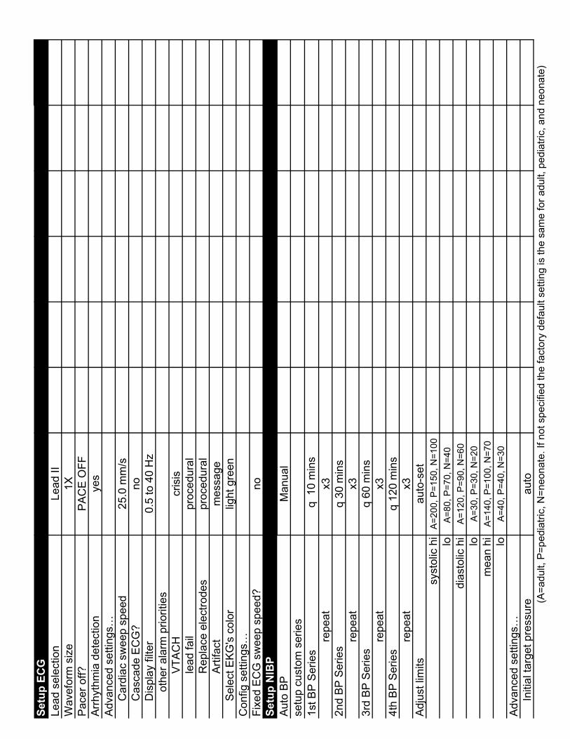
Setu
p EC
GLe
ad s
elec
tion
Lead
IIW
avef
orm
siz
e1X
Pace
r off?
PAC
E O
FFAr
rhyt
hmia
det
ectio
nye
sAd
vanc
ed s
ettin
gs…
C
ardi
ac s
wee
p sp
eed
25.0
mm
/s
Cas
cade
EC
G?
no
Dis
play
filte
r0.
5 to
40
Hz
oth
er a
larm
prio
ritie
s
V
TAC
Hcr
isis
lea
d fa
ilpr
oced
ural
Rep
lace
ele
ctro
des
proc
edur
al
A
rtifa
ctm
essa
ge
Sel
ect E
KG's
col
orlig
ht g
reen
Con
fig s
ettin
gs…
Fixe
d EC
G s
wee
p sp
eed?
noSe
tup
NIB
PAu
to B
PM
anua
lse
tup
cust
om s
erie
s1s
t BP
Serie
s q
10
min
sre
peat
x32n
d BP
Ser
ies
q 30
min
sre
peat
x33r
d BP
Ser
ies
q 60
min
sre
peat
x34t
h BP
Ser
ies
q 12
0 m
ins
repe
atx3
Adju
st li
mits
auto
-set
syst
olic
hi
A=20
0, P
=150
, N=1
00lo
A=80
, P=7
0, N
=40
dias
tolic
hi
A=12
0, P
=90,
N=6
0lo
A=30
, P=3
0, N
=20
mea
n hi
A=14
0, P
=100
, N=7
0lo
A=40
, P=4
0, N
=30
Adva
nced
set
tings
…
Ini
tial t
arge
t pre
ssur
e au
to(A
=adu
lt, P
=ped
iatri
c, N
=neo
nate
. If n
ot s
peci
fied
the
fact
ory
defa
ult s
ettin
g is
the
sam
e fo
r adu
lt, p
edia
tric,
and
neo
nate
)

Setu
p N
IBP
(con
tinue
d)
Lim
it al
arm
s pr
iorit
yw
arni
ng
o
ther
ala
rm p
riorit
ies
No
dete
rmin
atio
npr
oced
ural
Ove
rpre
ssur
epr
oced
ural
Pum
p tim
eout
proc
edur
al
T
otal
tim
eout
proc
edur
al
L
evel
tim
eout
proc
edur
al
Sel
ect N
IBP'
s co
lor
purp
leSe
tup
SpO
2Vi
ew W
avef
orm
?ye
sAd
just
lim
itshi
100
lo
90
Adva
nced
set
tings
…
View
sig
nal s
treng
th b
ar?
yes
Vi
ew S
pO2
PR?
no
Spot
che
ck e
nabl
eye
s
Car
diac
sw
eep
spee
d25
.0 m
m/s
Li
mit
alar
ms
prio
rity
war
ning
oth
er a
larm
prio
ritie
s
L
ost p
ulse
proc
edur
al
S
enso
r dis
conn
ecte
dpr
oced
ural
Rep
lace
cab
lepr
oced
ural
S
elec
t SpO
2's
colo
rw
hite
Setu
p R
ESP
Lead
to a
naly
zeA-
LII,
P-LI
I, N
- L1
View
wav
efor
m?
yes
Wav
efor
m s
ize
1XAd
just
lim
its
h
iA=
30, P
=60,
N=1
00lo
A=6,
P=1
0, N
=15
Adva
nced
set
tings
...
Res
p sw
eep
spee
d (m
m/s
)A/
P=12
.5, N
=6.2
5
Car
diog
enic
filte
r
auto
Li
mit
alar
ms
prio
rity
war
ning
oth
er a
larm
prio
ritie
s
R
esp
appr
oach
ing
war
ning
Lea
d Fa
ilpr
oced
ural
Sat
urat
ion
proc
edur
al(A
=adu
lt, P
=ped
iatri
c, N
=neo
nate
. If n
ot s
peci
fied
the
fact
ory
defa
ult s
ettin
g is
the
sam
e fo
r adu
lt, p
edia
tric,
and
neo
nate
)

Setu
p R
ESP
(con
tinue
d)
A
rtifa
ctpr
oced
ural
Se
lect
RES
P's
colo
rpr
oced
ural
Con
fig s
ettin
gs…
Tu
rn o
n R
ESP
with
EC
G?
noSe
tup
TEM
PU
nit o
f Mea
sure
°FC
hoos
e m
ode
pred
ictiv
eAd
vanc
ed S
ettin
gs…
oth
er a
larm
prio
ritie
s
D
isco
nnec
ted
proc
edur
al
T
wo
prob
es o
utpr
oced
ural
Tim
ed o
utpr
oced
ural
Pro
bes
sam
e ty
pepr
oced
ural
Che
ck p
robe
spr
oced
ural
S
elec
t TEM
P's
colo
rye
llow
Con
fig s
ettin
gs…
Al
low
°C u
nits
onl
y?no
Setu
p R
ECO
RD
ERpr
int o
n al
arm
novi
tals
sum
mar
y on
prin
tout
noAu
to p
rinto
ut o
f vita
ls s
umm
ary
OFF
setu
p co
ntin
uous
Wav
efor
ms
to re
cord
1 ch
osen
setu
p tim
ed
Cha
rt sp
eed
25.0
mm
/sLe
ngth
of s
trip
(in s
econ
ds)
8R
ecor
d ke
y pr
into
utat
bed
side
Con
fig s
ettin
gs…
se
tup
cont
inuo
us
Del
ayed
mem
ory
(in s
econ
ds)
8
Len
gth
of s
trip
(in s
econ
ds)
20
setu
p tim
ed
D
elay
ed m
emor
y (in
sec
onds
)4
(A=a
dult,
P=p
edia
tric,
N=n
eona
te. I
f not
spe
cifie
d th
e fa
ctor
y de
faul
t set
ting
is th
e sa
me
for a
dult,
ped
iatri
c, a
nd n
eona
te)

Oth
er S
yste
m S
ettin
gsAl
way
s di
spla
y ba
ttery
icon
?no
Adva
nced
Set
tings
…
Sel
ect c
olor
form
atfu
ll co
lor
A
djus
t key
clic
k vo
lum
e2
A
djus
t sys
tem
vol
ume
8C
onfig
set
tings
…Se
lect
dat
e fo
rmat
mm
/dd/
yySe
lect
tim
e fo
rmat
milit
ary
Lang
uage
engl
ish
Dis
play
uni
ts?
yes
Dis
play
lim
its?
yes
Con
fig H
ostC
omm
Uni
t add
ress
" "IP
add
ress
2.0.
0.0
Wav
efor
ms
to s
end
2 ch
osen
Rem
ote
acce
ssO
FFSe
rial 1
set
up
Star
tup
mod
eAS
CII
cmd
Ba
ud ra
te96
00Se
rial 2
set
up
Star
tup
mod
eAS
CII
cmd
Ba
ud ra
te96
00(A
=adu
lt, P
=ped
iatri
c, N
=neo
nate
. If n
ot s
peci
fied
the
fact
ory
defa
ult s
ettin
g is
the
sam
e fo
r adu
lt, p
edia
tric,
and
neo
nate
)
Not
es
SECTION 5 ASSEMBLY DRAWINGS & ELECTRICAL SCHEMATICS Assembly Drawings (Monitor Assembly & Disassembly) Front Case 1 ..................................................................................................... 5-1/2 Front Case 2 ..................................................................................................... 5-3/4 Rear Case 1 ...................................................................................................... 5-5/6 Rear Case 2 ...................................................................................................... 5-7/8 Electrical Schematics ECG Board – 315589........................................................................ 5-9 through 5-18 Main Board – 315592..................................................................... 5-19 through 5-42 Power Supply Board – 315593....................................................... 5-43 through 5-52 Keyboard......................................................................................................... 5-53/54 Probe Warmer................................................................................................. 5-55/56

Fascia, Key Pad, (english) - 701502Foot, Polyurethane - 732175
Assembly DrawingFront Case (1 of 2)page 5-1/2
1 2
34
7
6
5
1 - Cable Assy, Defib, to Main Board - 316701
2 - Cable Assy, ECG to Main Board - 316680
3 - PVC Tubing
4 - Pneumatic Tubing (NIBP) - 740185
7 - Temp Probe Housing - 705108
6 - Alaris Temperature Connectors - 608531
5 - Nellcor SpO2 Connector - 608530
Pneumatic hose connects to thebottom terminal of NIBP socket
Front Case - 705110
Rotor Knob- 733152
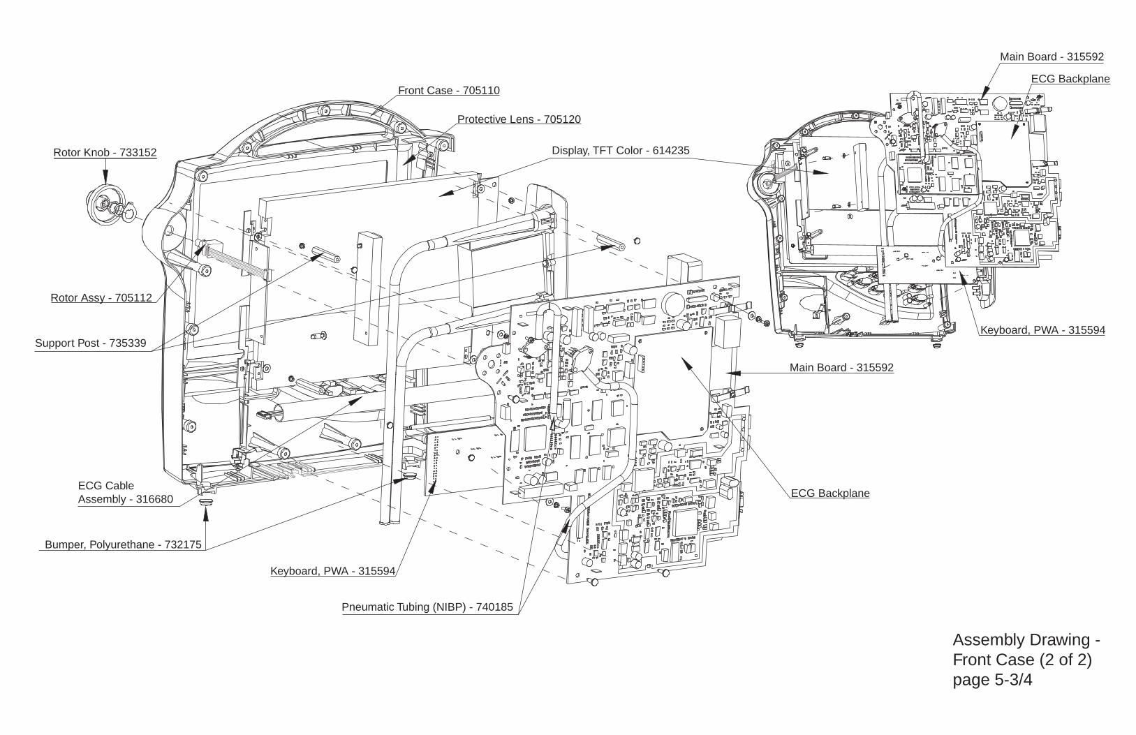
Assembly Drawing - Front Case (2 of 2)page 5-3/4
Rotor Assy - 705112
ECG Backplane
ECG Backplane
Bumper, Polyurethane - 732175
Front Case - 705110
Display, TFT Color - 614235
Protective Lens - 705120
Rotor Knob - 733152
Main Board - 315592
Main Board - 315592
Support Post - 735339
Pneumatic Tubing (NIBP) - 740185
ECG Cable Assembly - 316680
Keyboard, PWA - 315594
Keyboard, PWA - 315594

Pneumatic Assembly - 320744
PSU Module - 320757
Rear Case - 705116
NiMH Battery - 633177 (replaced as a whole)
Fan, DC - 680452
External DC Cable Assembly - 316694
AC Cable Assembly - 316698
Speaker Assembly - 320747
PSU Board - 315593
Note: The Circuit Boards depicted within this drawing are shown as unpopulated.
Vibration Dampers
Assembly DrawingRear Case (1 of 2)page 5-5/6
The battery retention screws are recessedbetween the cells on the rear case.
For NiMh battery removal/replacement:

Bumper - 732175
Bumper - 732175
Bumper - 732175
Battery Fuse/Holder
Bed Hook - 710123
DB9 Serial Connector
Velcro - 736249
Phillips Screw, #2 - 705132
Host Comms Cover - 705117
Antenna Blanking Plugs - 705119
External DC Cable
Assembly - 316694
DB15 Host
Comms Connector
AC Cable
Assembly - 316698
Rear Case - 705116
Assembly Drawing
Rear Case (2 of 2)
Host Comms Cover removed
page 5-7/8
- Indicates a screw removal point.
Note 1
Note 1: This particular screw is longer than all of the other screws.
It is critical to return this screw to the same slot; placement
elsewhere can potentially cause damage to the front of the
Monitor, requiring case replacement.
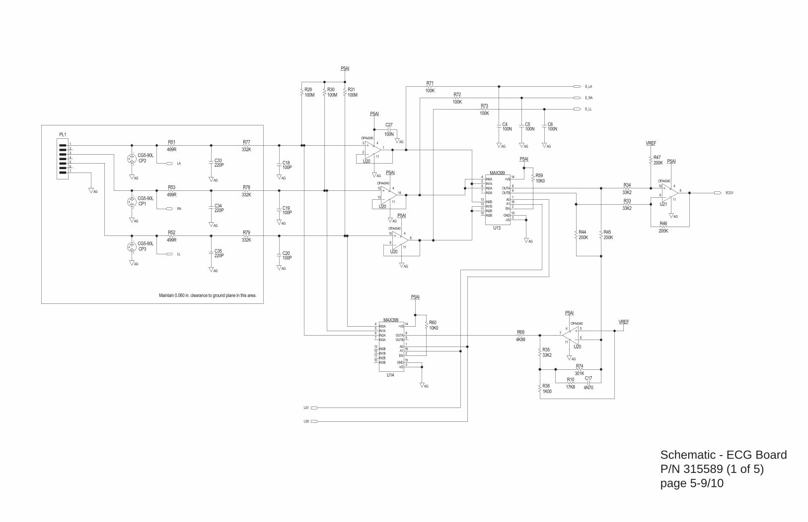
AG
OPA4340
OPA4340
OPA4340
OPA4340
33K2
33K2
33K2332K
332K
220P
220P
100P
100P
100P
499R
499R
MAX399
IN0A
IN1A
IN2A
IN3A
IN0B
IN1B
IN2B
IN3B
+VS
OUTA
OUTB
A0A1
EN
GND
-VS
MAX399
IN0A
IN1A
IN2A
IN3A
IN0B
IN1B
IN2B
IN3B
+VS
OUTA
OUTB
A0A1
EN
GND
-VS
AG
AG
100M100M100M
301K
200K
200K 200K
200K
1K0017K8
10K0
10K0
100K
100K
100K
4N70
100N 100N
AG
AG
AG
AG
AG
AG
AG
AG
AG AG AG
AG
P5AI
AG
AG
AG
P5AI
P5AI
VREF
VREF
AG
AG
100N100N
P5AI
P5AI
AG
332K
P5AI
P5AI
P5AI
499R
220P
OPA4340
4K99
CG5-90L
CG5-90L
CG5-90L
Maintain 0.060 in. clearance to ground plane in this area.
1
2
CP3
2
1
CP1
1
2
CP2
2
3
4
5
6
1
7
PL1
LS0
LS1
R69
10
9
4
11
8
U21
C33
R51 R77
C27 C4
LA
ECG1
E_RA
E_LL
E_LA
C6C5
C17
R73
R72
R71
R59
R60
R10
R38
R46
R45R44
R47
R74
R29 R30 R31
4
5
6
7
13
12
11
10
14
8
9
1
16
2
15
3
U14
4
5
6
7
13
12
11
10
14
8
9
1
16
2
15
3
U13
R53
R52
C19
C18
C20
C34
C35
R79
R78 R34
R33
R35
1
3
2
11
4
U20
7
5
6
11
4
U20
8
10
9
11
4
U20
14
12
13
11
4
U20RA
LL
Schematic - ECG BoardP/N 315589 (1 of 5)page 5-9/10
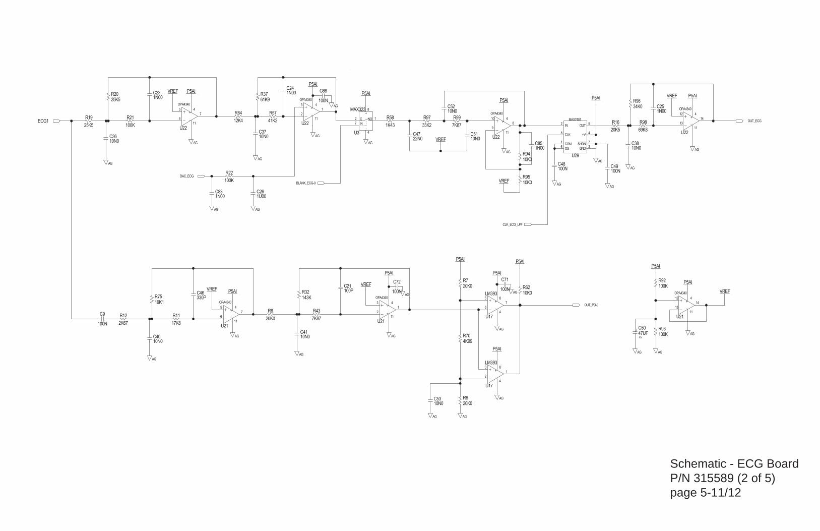
Schematic - ECG BoardP/N 315589 (2 of 5)page 5-11/12
47UF16V
AG
1N00
10K0
VREF
OPA4340
OPA4340
OPA4340
OPA4340
OPA4340
OPA4340
OPA434034K0
10N010N0
10N0
10N0
10N0
10N010N0
1N00
1N00
1U00
AG100N AG
100N
AG
100N
7K87
7K87
69K8
61K9
4K99
41K2
2K67
25K5
20K525K5
20K0
20K0
20K0
1K43
19K1
17K8
143K
12K4
10K0
100K
100K
100K
100K
330P
22N0
100P
100N100N
100N
P5AI
AG AG
MAX323+
-
C
IN
NO
AG
MAX7401
IN
CLK
COM
OS GND
SHDN
+V
OUT
LM393AG
AG
VREFVREF
P5AIP5AI
AG
AG
P5AI
AG
P5AIVREF
AG
AG
VREF
AGAG
LM393VREF
AG
AG
P5AI
AG
P5AI
AG
AG
AG
P5AI
AG
P5AI
AG
AG
AG
P5AI
P5AIP5AI
P5AI
P5AI
10N0
VREF
33K2
AG
1N00
10K0
1N00C85
R94
C24
CLK_ECG_LPF
R97
BLANK_ECG-0
C53
5
6
4
8
7
U17
OUT_PD-0
ECG1
1
8
4
2
3
U17
2
8
1
6 3
7
4
5
U29
8
4
2
7
1
U3
C9
C48C49
C21
C47
C46
R21
R22
R92
R93
R62
R84
R32
R11
R75
R58
R8
R7
R6
R19R16
R20
R12
R57
R70
R37
R98
R43
R99
C66
C71C72
OUT_ECG
C26
C25
C23
C36C51
C52
C38
C37
C41C40
R96
5
6
4
11
7
U22
3
2
4
11
1
U2210
9
4
11
8
U22
12
13
4
11
14
U22
5
6
4
11
7
U21
3
2
4
11
1
U21
12
13
4
11
14
U21
R95
C83
DAC_ECG
C50

Schematic - ECG BoardP/N 315589 (3 of 5)page 5-13/14
100R
100R
150K5K90
20K0
20K0
AG
100P
AG
33P0
4K99
P5AI
AG
1M00
AG
100N
10N0
100NAG
10N0
1U00
1U00
K2
S1A
S1B
S2A
S2B
A1
K1
A2
AQW214S750R
499K
1K00
10K0
100P
100N
33N0200K
16K2
33P010P0
AG
VREF
GND
CO
-
NCCC +
NO
IN
MAX383
AG
AGAG
AG
VREF
AG
P5AI
MMBD914
P5AI
VREF
VREF
AG
P5AI
100NAG
AG
AG
AG
AG
P5AI
P5AI
P5AI
P5AI
P5AI
3N30 499R
3N30 499R
499R
191K
GND
CO
-
NCCC +
NO
IN
MAX383
VREF
33K2
AG
1:1
P5AI
AG
1M00
AGAG
3N30
AGAG
AG
AG
1M00 220P220P220P
OPA4350
OPA4350
OPA4350
OPA4350
1K65 1K65
2K67
2K67
10K0
OPA4340
OPA4340
OPA4340
34K0
1N00 47UF16V
Route CLOCK signals away from these parts and connections.
Maintain 0.060 in. clearance to ground plane in this area.
Place close to U23
Place close to T1
Maintain 0.060 in. clearance to ground plane in this area.
Make GND connections short and fat.
C7C84
R100
14
12
13
11
4
U24
8
10
9
11
4
U24
7
5
6
11
4
U24
R101
R82
R81
R50R49
1
3
2
11
4
U23
7
5
6
11
4
U23
8
10
9
11
4
U23
14
12
13
11
4
U23
C80 C79 C78R108
C2
R107
1
4
8
5
T1
CLK_RESP_DEMOD
R85
CLK_RESP_MOD
13
1
14
43
11
16
15
U31
R76
LLR55
LAR54C1
RAR56C3
C75
BL_RESP
RLS1-0
RLS2-0
CR1
13
8
14
56
11
9
10
U31
C44C16
R80
R48 C8
C10
C22
R41
R40
R28
R17
4
8
7
6
5
1
2
3
U30
C29
C30
C54
C39
C76
OUT_RESP
C77
R106
R109
C81
C82
R63
R105
DAC_RESP
R36 R26
R39
R104

Schematic - ECG BoardP/N 315589 (4 of 5)page 5-15/16
AG
10N0
AG
10N0
P5DI
P5AI
AG
10N0
10N0
10N010N0
10N0
10N0
AG
11.0592MHZ
33P033P0
74HC390
QB
QC
QD
VCC
CLOCKA-0
CLOCKB-0
QA
RESET
GND
74HC390
QB
QC
QD
VCC
CLOCKA-0
CLOCKB-0
QA
RESET
GND
100N
25K525K525K525K525K525K5
AG
P5DI
AG
AG
P5DI
AG
AG
P5DI
74HC161
P1
P2
P3
CLOCK
RESET-0
LOAD-0
ENABLE_P
ENABLE_T GND
VCC
RCO
Q3
Q2
Q1
P0 Q0
AG
P5DI
P5DI
AG
74HC393
Q4
Q3
Q1
Q2
GND
RESET
CLOCK-0
VCC
74HC393
Q4
Q3
Q1
Q2
GND
RESET
CLOCK-0
VCC
AG
AG
AG
74HC164
CLOCK
RESET-0
GND
VCC
A1
A2
QA
QB
QC
QD
QF
QG
QH
QE
AG AG
P5AI
AG
10N0
AG
AG
MAX323+
-
C
IN
NO
P5AI
74HC00
+
-
P5DI
AG
P5DI
AG
P5DI
74HC00
+
-
AG
P5DI
74HC00
+
-
P5DI
AG
AG
P5DI
AG
74HC00
+
-
AG
P5DI
1K00
ADUC812
48DVDD3
47DGND3
34DVDD2
21DGND1
20DVDD1
35DGND2
AVDD5
XTAL132
RESET15
8VREF
7CREF
9DAC0
14P1.7/ADC7
13P1.6/ADC6
12P1.5/ADC5/~SS
11P1.4/ADC4
4P1.3/ADC3
3P1.2/ADC2
2P1.1/ADC1/T2EX
1P1.0/ADC0/T2
P0.0/AD043
P0.1/AD144
P0.2/AD245
P0.3/AD346
P0.4/AD449
P0.5/AD550
P0.6/AD651
P0.7/AD752
P2.0/A08/A1628
P2.1/A09/A1729
P2.2/A10/A1830
P2.3/A11/A1931
P2.5/A13/A2137
P2.6/A14/A2238
P2.7/A15/A2339
P3.2/~INT018
P3.3/~INT1/MISO19
P3.0/RXD16
P3.1/TXD17
SCLOCK26
SDATA/MOSI27
P3.4/T022
P3.5/T1/~CONVST23
P3.6/~WR24
P3.7/~RD25
~EA40
~PSEN41
ALE42
XTAL233
6AGND
P2.4/A12/A2036
10DAC1
AG P/D_NUM=MMT-102-01-T-SH
OPA4340
AG
AG
GND
VIN
VOUT
MAX6002
AG
P5AI
P5DI
P5DI
GND
VCC
RESET
MAX810
Spare Parts
Keep this trace short.
1
3
2U37
3
1
2U36
1
3
2
11
4
U24
2
1J2
FLASH-0
DAC_RESP
DAC_ECG
EN_RESPCLK
EN_ECG40
EN_ECG100
CLK_RESP_MOD
CLK_RESP_DEMOD
E_LL
E_LA
E_RA
BL_RESP
OUT_RESP
OUT_ECG
U1
R102
14
7
4
56
U35
14
7
9
108
U35
14
7
1
23
U3514
7
12
1311
U35
8
4
6
3
5
U3
C28
8
9
7
14
1
2
3
4
5
6
1011
12
13
U28
RLS2-0
RLS1-0
CLK_ECG_LPF
6
5
3
4
7
2
1
14
U34
8
9
11
10
7
12
13
14
U34
4
5
6
2
1
9
7
10 8
16
15
11
12
13
3 14
U33
D_TO_HOST
D_FROM_HOST
LS0
LS1
BLANK_ECG-0
OUT_PD-0
R86 R87 R88 R89 R90 R91
C11
5
6
7
16
1
4
3
2
8 U25
11
10
9
16
15
12
13
14
8 U25
C63 C64
X1
C58
C55
C59 C60
C56
C57
C45 C31

Schematic - ECG BoardP/N 315589 (5 of 5)page 5-17/18
AG
LP2986IMX-5.0
IN
ERR
GND
OUT
SENSESD
TAP
FB
3V0
P_RAW
1K431K43
4U70
10N0
10N0
MMBT3906LT1
E
B
C
AG
3K83
100N
100N
15K0
15K0
604R
604R
AG
DG
DG
DG
DG
DG
DG
P5AI
+5V
+5V
P5DI
AG
AG
DG
+5V
DG
100N
AG
100N
AG
1:1.6
P5DI
4U70
AG
P_RAW
AG
RB160L-40
RB160L-40
D2
D1FS
NC
SD
GND2GND1
VCC
MAX253CSA
100UF10V
10U0+
AG
HCPL-261N
GND
VCC
CATHODE
ANODE
VO
ENAB
HCPL-261N
GND
VCC
CATHODE
ANODE
VO
ENAB
NOTE: Host must provide pull-up on output data line.
Isolation Barrier
Maintain 0.050 in. clearanceto ground plane in this area.
5
8
3
2
6
7
U7
5
8
3
2
6
7
U6
C65C32
8
13
5
4
72
6
U8
CR3
CR2
5
4
3
2
1
SK1
1 2
L1
6
5
4
1
2
3
T2
C62
C13
R2
R3
R68
R67
C15
C12
R9
2
1
3
Q1
C42
C43
21
L2
R4 R5
CR4
4
7
1
5
68
3
2
U18
D_FROM_HOST
D_TO_HOST

0R0
0R0
0R0
0R0
0R0
0R0
0R0
0R0
0R0
0R0
0R0
0R0
0R0 0R
0
0R0
0R0
0R0
0R0 0R0
0R0
0R0
0R0
0R0
0R0
0R0
0R0
0R0
0R0
0R0
0R0
0R0
0R0
0R0
0R0
0R0
0R0
0R0
0R0
0R0
0R0
0R0
0R0
0R0
0R0
0R0
0R0 0R0
0R0
0R0
0R0
0R0
0R0
0R0
0R0
0R0
10K
10K
2K21
10K
10K
10K
47uF16V
47uH
+3V3D823
100nF 100nF
100nF100nF
+3V3D823
+3V3D823
100nF
+3V3D823
10K
10K
10K
10K
10K
10K10K
10K
+3V3D
100nF
10K
+3V3D823
+3V3D823+3V3D823
NF
VRAM
22pF
4.915MHz 1K0
22pF
+3V3D823 +3V3D823
10K
10K
10K
10K
10K
+3V3D
LV244
G
A3
A2
A1
Y3
Y4
Y2
Y1
A4
LV244
G
A3
A2
A1
Y3
Y4
Y2
Y1
A4
+3V3D823
10K
10K
+3V3D823
+3V3D823
100nF
+3V3D823
+3V3D823 100nF+3V3D823
100nF
+3V3D823
100nF10uF16V
+3V3D823
10K
10K
10K
+3V3D823
+3V3D823
10K
4K75
4K75
2K21
2K21
2K21
10K
10K
10K
10K
10K
10K
10K
MPC823
VSSSYN
VSSSYN1
KAPWR
XTALOUT
XTALIN
EXTCLK
VDDL
IP_B0
IP_B3
FREEZE
BB
TA
GPL_B5
CS1
CS3
NC1
VDDSYN
XFC
PORESET
SRESET
HRESET
MODCK2
SPKROUT
DSCK
IP_B4
BURST
BUSREQ
BURSTINH
GPL_B4
CS2
CS7
CS4
NC2
IRQ6
IRQ3
WAIT_B
RSTCONF
NC3
IP_B6
IP_B1
IP_B5
BUSGRANT
TR_ERR_ACK
GPL_A5
R/W
CS6
GPL_A2
CAS/OE
CLKOUT
D30
IRQ5
IRQ4
TEXP
MODCK1
IP_B2
IP_B7
IRQ2
TRANS_STRT
GPL_A4
CS0
CS5
GPL_A3
WE2
WE0
D07
D29
D31
D26
VDDH1
VDDH2
VDDH3
VDDH4
VDDH5
VDDH6
VDDH7
VDDH8
GPL_A0
NC4
TSIZ1
BS_AB1
D06
D21
D24
D28
VDDH9
GND1
GND2
GND3
GND4
GND5
GND6
VDDH10
BS_AB3
A26
TSIZ0
A31
VDDL1
D19
D20
D25
VDDH11
GND7
GND8
GND9
GND10
GND11
GND12
VDDH12
A18
A22
A30
A28
D5
D16
D18
D22
VDDH13
GND13
GND14
GND15
GND16
GND17
GND18
VDDH14
A24
A25
A23
A29
D3
D2
D14
D15
VDDH15
GND19
GND20
GND21
GND22
GND23
GND24
VDDH16
NC5
A21
A20
VDDL2
D11
D9
D10
D17
VDDH17
GND25
GND26
GND27
GND28
GND29
GND30
VDDH
A17
A16
A19
A27
D1
D4
D27
D23
VDDH18
GND31
GND32
GND33
GND34
GND35
GND36
VDDH19
A10
A13
A14
A15
D0
D8
D13
D12
VDDH20
VDDH21
VDDH22
VDDH23
VDDH24
VDDH25
VDDH26
VDDH27
A6
A12
A9
A11
IRQ0
IRQ1
IRQ7
SHIFT/CLK
LD4
PC06
LCD_C
PC08
NC6
SMRXD2
SMTXD1
TDO/DSDO
NC7
LCD_A
A07
A08
NC8
VSYNC
HSYNC
LD2
LD6
PC[5]
PB[18]
TOUT1
PC[10]
NC9
TRST
I2CSCL
PC[13]
SPIMOSI
SPICLK
PA[15]
PD6
LD0
LD5
LD8
PB16
TOUT2
LCD_B
PC09
PB22
PC11
TDI/DSDI
TMS
TXD2
RXD2
PA14
PC15
LD1
LD3
LD7
PC04
PC07
PA05
VDDL4
CLK1
SMTXD2
PB23
SMRXD1
TCK/DSCK
PC12
I2CSDA
SPIMISO
PC14
10M5%
0R0
49R9
49R9
49R9
49R9
0R0
NF
NF
NF
0R0
0R0
0R0
0R0
+3V3D8231K0
1K0
100uF10V
BAS16
10nF
1K0
A[31:6]
A27
A26
A11
A21
A20
A17
A16
A19
A13
A14
A15
A29
A23
A25
A24
A28
A30
A22
A18
A12
A31
A9
A8
D[31:0]
D18
D10
D9
D17
D31
D26
D7
D29
D22
D3
D15
D11
D14
D2
D9
D10
D0
D8
D30
D1
D4
D27
D23
D13
D12
D5
D16
D19
D20
D25
D6
D21
D24
D28
D12
D11
D8
D7
D5
D4
R139
HRST[L]
C102
3 1
D19
ROTOR
LCD_BACKLIGHT[L]
C2
R154
R108
WARM_B
WARM_T
RESET[L]
SWG
R418
R417
R420
R419
R415
R414
R413
R416
I2CSCL
FS_ARMED[H]
REM_AL_REQ[H]
FAIL_PRI[L]
HSYNC
VSYNC
R392
R391
LCD_R2
R390LCD_CLK
CLKOR386
R202
4
3
2
1
5
PL8
1
9
7
5
3
2
6
8
10
4
PL12
ET7
SRESET
R25
D12
E1
E2
B15
B16
C2
C3
C4
C5
C7
C8
C9
C10
C11
C12
C13
C14
C15
C16
D1
D2
D3
D4
D5
D6
D7
C1
C6
A1
A2
A3
A4
A5
A6
A7
A8
A9
A10
A11
A12
A13
A14
A15
A16
B1
B2
B3
B5
B7
B4
B6
B8
B9
B10
B11
B12
B13
B14
M14
D8
D9
D10
D11
N1
N2
J1 J2 J3 J4 J5 J6
M16J7
M15J8 J9
J10
J11
J12
J13
M11
J14
M10
J15
M9
J16
M8
K1
M7
K2
M6
K3
M5
K4
M4
K5
M3
K6
M2
M1
L16
K7
K8
K9
K10
K11
L14
L13
L12
L11
K12
K13
K14
K15
L10
L9
L8
L7
L6
L5
L4
L3
L2
L1
N3
N4
N5
N6
N7
N8
N9
N10
N11
N12
N13
N14
N15
N16
P1
P2
P3
P4
P5
P6
P7
P8
P9
P10
P11
P12
P13
P14
P15
P16
R1
R2
R3
R4
R5
R6
R7
R8
R9
R10
R11
R12
R13
R14
R15
R16
T1
T2
T3
T4
T5
T6
T7
T8
T9
T10
T11
T12
T13
T14
T15
T16
E3
E4
E5
E6
E7
E8
E9
E10
E11
E12
E13
E14
E15
E16F1
F2
F3
F4
F5
F6
F7
F8
F9
F10
F11
F12
F13
F14
F15
F16
G1
G2
G3
G4
G5
G6
G7
G8
G9
G10
G11
G12
G13
G14
G15
G16
H1
H2
H3
H4
H5
H6
H7
H8
H9
H10
H11
H12
H13
H14
H15
H16
K16
D16
D15
D14
D13
M13
M12
L15
U12
DSD1_TD1
RESET[L]
TEMP_DATA[L]
R371 BS3[L]
R153
R151
R152
CYCLE_PWR
R150
CS6[L]
R146
R143
R58
R293
R292
R141
R145
R136
SWF
R217
R216
R215
C115 C3
C227
C226
C223
GPL1
CS0[L]
R350
RESET[L]
R144
19
15
13
11
5
3
7
9
17
U72
1
6
4
2
14
12
16
18
8
U72
+3V3D823;20GND;10
LATCHED_OVC_3V
LCD_BRIGHTNESS
SRESET
DSD0_TD0
TCK_DSCK
TMS
R155
R149
R148
R142
R137
C170
R95XL5
C171
R28
R140
GPL3
BS2[L]
BS0[L]
BS1[L]
GPL0
I2CSDA
HOST_RX2
TX1
UNFIL_0VP[L]
PRINTER_PRES[L]
LCD_B3
LCD_G4
LCD_R3
LATCHED_OVP_3V
PRINTER_RX
PRINTER_TX
TIMECHK
ADC_BUSY[L]
PRINTER_CTS
LCD_G1
SOUND_TIMER2
SPO2_RESET
LCD_B2
LCD_G2
LCD_R4
SPI_CLK
SPI_MOSI
RESET[L]
TEMP_R
SOUND_TIMER1
PNEU_RESET
CHA
LCD_B4
LCD_R1
HOST_TX2
RX1
TEMP_O
LCD_B1
CHB
LCD_G3
SWA
CS2[L]
CS3[L]
CS1[L]
SWE
SWG
SWH
GPL2
SWC
SWD
SWB
NIBPCS[L]
CS7[L]
TCK_DSCK
SWD
DSD1_TD1
C1
LCDOE[L]
R261
R349 R352
R356
R355
R354
R353
R357
C218
CS5[L]
GPL5
C224 C225
C228C229
L7
C195
R256
R313
R368
R138
R369
R370
R59
ET5 ET6
R57
R203
R204
R205
R206
R253
R254
R255
R243
R244
R246
R245
R248
R247
R249
R250
R251
R252
R207
R208
R209
R210
R211
R212
R213
R214
R379
R359
R241
R240
R239
R238
R237
R236
R235
R234
R242
R230
R233
R232
R231
R229
R228
R227
R226
R225
R224
R223
R222
R221
R220
R219
R218
R378
Schematic - Main BoardP/N 315592 (1 of 12)Page 5-19/20
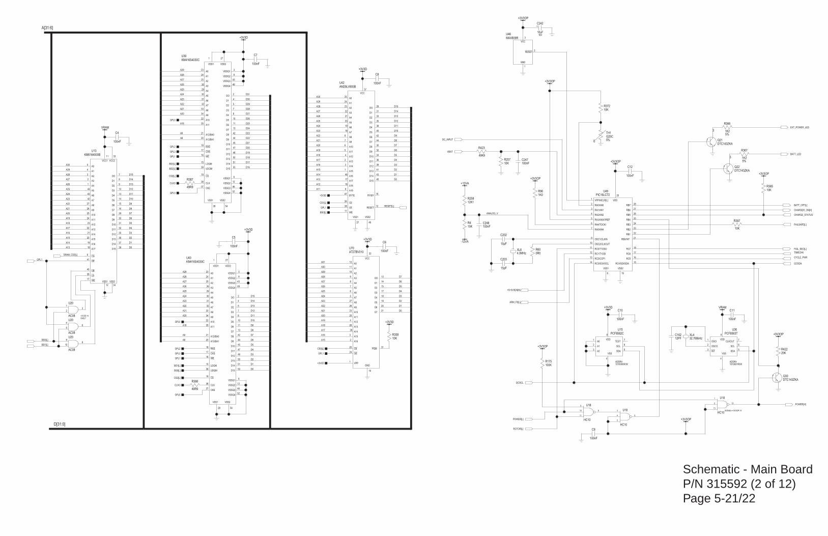
Schematic - Main BoardP/N 315592 (2 of 12)Page 5-21/22
+3V3OP
+3V3OP
+3V3OP
+3V3OP
+3V3OP
+3V3OP
49K9
20K
DTC143ZKA
10uF16V
12K1
15K
-12VA
+12VA
49R9
VDD
VSS
A0
A1
A2
SCL
SDA
TEST
PCF8582C
0R0
1K25%
A19
RESET
D8
WE
A0
A1
A2
A3
A4
A5
A6
A7
A8
A9
A10
A11
A12
A13
A14
A15
D2
D3
D4
D5
D6
OE
CE
D7
DO
D1
D9
D10
D11
D12
D13
D14
D15
A16
A17
BYTE RY/BY
VSS2VSS1
VCC
AM29LV800B
A18
DTC143ZKA
10K
+3V3D
10K 32.768kHz
100nF
100nF
100nF
100nF
100nF
100nF
100nF
100nF
KM416S4030C
A13/BA1
A11
VSS2
VSSQ3
VSSQ2
UDQM
LDQM
CAS
RAS
D8
A0
A1
A2
A3
A4
A5
A6
A7
A8
A9
D6
CKE
D7
DO
D1
D9
D10
D11
D12
D13
D14
CS
WE
D15
CLK
VSSQ1
VDDQ3
VDDQ4
VDDQ2
VDDQ1
VSSQ4
VSS1
A10
A12/BA0
VDD2VDD1
D2
D3
D4
D5
KM416S4030C
A13/BA1
A11
VSS2
VSSQ3
VSSQ2
UDQM
LDQM
CAS
RAS
D8
A0
A1
A2
A3
A4
A5
A6
A7
A8
A9
D6
CKE
D7
DO
D1
D9
D10
D11
D12
D13
D14
CS
WE
D15
CLK
VSSQ1
VDDQ3
VDDQ4
VDDQ2
VDDQ1
VSSQ4
VSS1
A10
A12/BA0
VDD2VDD1
D2
D3
D4
D5
+3V3D
+3V3D
PCF8563T
VDD
VSS
OSCI
OSCO
INT
SCL
SDA
CLKOUT
15pF
15pF
VRAM
+3V3D
4.0MHz
1K0
+3V3D
KM6164000B
VCC2
D8
VSS2WE
A0
A1
A2
A3
A4
A5
A6
A7
A8
A9
A10
A11
A12
A13
A14
A15
D2
D3
D4
D5
D6
LB
OE
UB
D7
VCC1
DO
D1
D9
D10
D11
D12
D13
D14
D15
A16
A17
CS
VSS1
AC08
+3V3D
G25C5%0
1K25%
10K
10K
AC08
AC08
MAX809R
RESET
GND
VCC
PIC16LC72
VSS2
VPP/MCLR[L]
RA0/AN0
RA1/AN1
RA2/AN2
RA3/AN3/VREF
RA4/TOCKI
RA5/AN4
OSC1/CLKIN
OSC2/CLKOUT
RC1/T1OSI
RC2/CCP1
RC0/T1OSO
RC3/SCK/SCL RC4/SDI/SDA
RC5
RC6
RC7
RB0/INT
RB1
RB2
RB3
RB4
RB5
RB6
RB7
VSS1
VDD
PGM
A15
A16
A0
A1
A2
A3
A4
A5
A6
A7
A8
A9
A10
A11
A12
A13
A14
O2
O3
O4
O5
O6
OO
O1
VPP
OE
CE
GND
VCC
AT27BV010
O7
49R9
10K
DTC143ZKA
VRAM
+3V3OP
100K
12PF
HC10
HC10
HC10
+3V3OP
100nF
100nF
100nF
ADDR=ADDR=1010001R/W1010000R/W
C247
C248
C10
9
10
11
8
U18
6
5
4
3 U18
1
2
13
12
U18
SIGNAL=+3V3OP;14
C162
R175
VBAT
POWER[L]
POWER[H]
2
1
3
Q22
ANALOG_V
BS0[L]
GPL5
ARM_FS[L]
R397
I2CSDA
CYCLE_PWR
ROTOR[L]
I2CSCL
+5+3V3EN[H]
GPL5
CLKO
R387CS2[L]
31
3
2
12
11
10
9
8
7
6
5
27
26
23
25
4
28
29
15
17
18
19
20
13
14
1
24
22
16
32
21
U70
19
1
2
3
4
5
6
7
9
10
12
13
11
14 15
16
17
18
21
22
23
24
25
26
27
28
8
20
U49
2
1
3
U46
4
56
U20
9
108
U20
R257
R372
TIMECHK
FAIL_SEC[L]
R366
TH1
1
23
U20
+3V3D;14GND;7
BS0[L]
33
29
34
17
5
4
3
2
1
44
43
42
27
26
25
24
23
22
21
20
9
10
13
14
15
39
41
40
16
11
7
8
30
31
32
35
36
37
38
19
18
6
12
U13
BS1[L]
EXT_POWER_LED
A16
A15
A17
A11
A12
A18
A8
A9
A9
A20
A21
A22
A23
A24
A25
A26
A27
A28
A29
A13
A14
A15
A16
A17
A18
A19
A20
A21
A22
A23
A24
A25
A26
A27
A28
A29
A30
A[31:6]
A18
A19
A20
A21
A22
A23
A24
A25
A26
A27
A28
A29
A30
A31
A29
A28
A27
A26
A25
A24
A23
A22
A21
A20
A30
A29
A28
A27
A26
A25
A24
A23
A22
A21
A20
A19
A18
A17
A16
A15
A14
A13
A18
A8
RESET[L]
R96
XL6
C202
D[31:0]
D0
D1
D2
D3
D4
D5
D6
D7
D8
D9
D10
D11
D12
D13
D14
D15
D0
D1
D2
D3
D4
D5
D6
D7
D8
D9
D10
D11
D12
D13
D14
D15
D0
D1
D2
D3
D4
D5
D6
D7
D16
D17
D18
D19
D20
D21
D22
D23
D24
D25
D26
D27
D28
D29
D30
D31
D0
D1
D2
D3
D4
D5
D6
D7
D8
D9
D10
D11
D12
D13
D14
D15
GPL0
GPL2
GPL3
GPL1
BS2[L]
BS3[L]
BATT_OFF[L]
CHARGER_ON[H]
C203
+3V3D
GPL1
CS0[L]
BS0[L]
GPL1
CS1[L]
+3V3D
GPL1
SRAM_CS3[L]
8
4
1
2
3
6
5
7
U36
DC_INPUT
GPL2
GPL3
GPL1
CS2[L]
GPL0
20
35
54
46
12
39
15
17
18
42
23
24
25
26
29
30
31
32
33
34
5
7
8
10
11
37
13
2
4
44
45
47
48
50
51
19
16
53
38
6
43
49
9
3
52
28
22
21
271U39
20
35
54
46
12
39
15
17
18
42
23
24
25
26
29
30
31
32
33
34
5
7
8
10
11
37
13
2
4
44
45
47
48
50
51
19
16
53
38
6
43
49
9
3
52
28
22
21
271U40
C4
C5
C6
C7
C8
C9
C11
C12
XL4R358
CHARGE_STATUS
R365
2
1
3
Q21
9
12
30
11
25
24
23
22
21
20
19
18
8
7
6
5
4
3
2
1
33
35
38
40
42
28
26
44
29
31
32
34
36
39
41
43
45
48
17
47 15
4627
37
16
U42
R367
BS1[L]
R60
8
4
1
2
3
6
5
7
U15
R388CLKO
BATT_LED
FAILSAFE[L]R4
R258
C242
3
1
2 Q30
R422
R423

Schematic - Main BoardP/N 315592 (3 of 12)Page 5-23/24
VBAT
100K
1K0
20K
1M0
15K
10R
10R
27K4
0R0
100nF
+12VA
AD822
10uF16V
47nF3K3
18K
+5VD;16GND;8
HCT259
G
D
S0
S1
S2
Q7
Q5
Q4
Q2
Q1
Q0
Q3
Q6
CLR
+5VD;16GND;8
HCT174
6D
5D
4D
3D
2D
1D
6Q
5Q
4Q
3Q
1Q
2Q
CLRCLK
47uF16V
100nF
+5VD
+5VD
+5VD
+5VD
47uF35V
10uF16V
10uF16V
10uF16V
1K0
30K
+5VD
LM393
+5VD
MPX2050
VS
VOUT+
VOUT-
GND
MPX2050
VS
VOUT+
VOUT-
GND
AD822
AD822
AD822
ANA+
BAS16
+5VD
100nF
100nF
330nF
LM78L12
G1 G4G2 G3
VIN VOUT
-12VA
100nF
10K
10M5%
100nF
100nF
100nF
ANA+
100nF
+12VA
100nF
100nF
750R0.1%
21K0.1%
+12VA
549R0.1%
AD620+
-
+VS
-VS
REF
100nF
+12VA
100nF
750R0.1%
549R0.1%100nF
21K0.1%
AD620+
-
+VS
-VS
REF
100nF
-12VA
100nF
30K
100nF
-12VA
REF-01
VIN VOUT
TRIM
GND
100nF
100nF
330K
330nF
ANA-
100nF
LM78L05
G1 G4G2 G3
VIN VOUT
+12VA
100nF
+5VD
+5VD
+12VA
LTC1604
AIN-
VREF
REFCOMP
CS
CONV
RD
BUSY
AVDD1
D0
D1
D2
D3
D4
D5
D6
D7
D8
D9
D10
D11
D12
D13
D14
D15
VSS
AGND4
AGND3
AGND2
AGND1
AVDD2
AIN+
SHDN
OGND
DGND
DVDD
OVDD
LM393
1uF16V
DG408
DS1
S2
S3
S4
S5
S6
S7
S8
A0
A2
A1
V+
V-
EN
14 DGND
2N7002
-12VA
+12VA
100nF
+12VA
+5VD
+3V3D
510R
1nF
100nF2u225V
100nF
47uF35V
LM79L12
VOUT
G3
VIN1
VIN2
VIN3
VIN4
LM79L05
VOUT
G3
VIN1
VIN2
VIN3
VIN4
HCT32
HCT32
HCT32
HCT32
HCT32
470nF
100nF
HCT32
10K
AD822
AD822
AD822
AD822
10K
100nF
47uF35V
BAT54S
10uF16V
1M0
90K90.1%
10K0.1%
21K0.1%
10K0.1%
41K2
9K090.1%
1K0
10K
68K1
49K9
10KCW
10KCW
ADULT OP Adjust
NEO OP AdjustVR1
VR2
R46
R92
R157
R421
R16
R15
R73
R14
R52
R24
R407
C119
1
2
3
CR1
C206
C232
R389
5
6
7
U75
5
6
7
U58
5
6
7
U57
83
24
1
U57
R156
1
23
GND;7+5VD;14
U62
C25
C106
4
56
U62
4
56
U61
1
23
GND;7+5VD;14
U61
9
108
U61
12
1311
U61
1
5
2
3
6
7
U33
1
5
2
3
6
7
U30
C207
C18
C140 C17
C101
R13
C26
1
2
3
Q7
84
5
6
7
12
11
10
9
1
15
2
16
13
3
U55
C130
5
6
7
U53
2
3
4
32
31
30
27
35
26
25
24
23
22
21
20
19
18
17
16
15
14
13
12
11
34
28
10
8765
9
29
36
1
33
U29
C15
2 73 6
8 1
U56
C24
C160
R305
C33
C32
2 6
5
4
U17
C16
R274
C31
C29
3
2
6
7
45
8
1
U47
R80
C14
R93
R18
C27
C34
3
2
6
7
45
8
1
U48
R94
R81
R19
C35
C13
C19
C20
C21
C22
R26
R158
C23
2 73 6
8 1
U54
C161
C28
C30
1 3
D5
83
24
1
U58
83
24
1
U59
5
6
7
U59
3
2
4
1
PT2
3
2
4
1
PT1
83
24
1
U53
R275
R98
C116
C118
C120
C208
C211
C174
14
13
11
6
4
3
15
12
10
7
2
5
19
U24
14
13
1
2
3
12
10
9
6
5
4
7
11
15
U51
R91
R6 C144C117
83
24
1
U75
C231
R61
R105
R1
R2
R70
R304
R306
R384
R408
BS0[L]
TH_REF
TH_REF
PT2_REF
ECG_EN[L]
DEFIBEN[L]
NIBPCS[L]
A24
A29
A30
A[31:6]
A28
A29
A30
A27
A25
A26
DEFLATE
DUMP[L]
FLT_0VP[L]
PNEU_CS[L]
D0
D[31:0]
D15
D14
D13
D1
D2
D3
D4
D5
D6
D7
D8
D9
D10
D11
D12
D13
D14
D15
ADC_BUSY[L]
ANA_SEL
PUMP_ON
RESET[L]
PT1_REF
PT1
CONV_ST[L]
RD_RES[L]
ADC_NAP[L]
PT2
12V_ON[H]
PUMPC
ADULT[L]
UNFIL_0VP[L]
UNFIL_0VP5V[L]

Schematic - Main BoardP/N 315592 (4 of 12)Page 5-25/26
+3V3D
HCT32
HCT32
10K
1M0
10nF
100nF
3.6864MHz
22pF
22pF
XR16C2850
-RIA
-CDA
INTB
-CSB
A1
A2
D0
D1
D2
D3
D4
D5
D6
D7
A0
TXB
RXB
XTAL2
RESET
-IOR
-IOW
GND
XTAL1
-DTRA
-DTRB
OPA
OPB
TXA
RXA
-CSA
VCC
INTA
-TXRDYB
-RXRDYB
-RXRDYA
-TXRDYA
-RTSA
-RTSB
-DSRB
-CDB
-DSRA
-RIB
-CTSB
-CTSA
+5VD
AC08
HCT32
HCT32
+3V3D
CONNECTOR
ECG
CS7[L]
CS5[L]
5
4
3
2
1
PL10
TO_SPO2
FROM_SPO2
D[31:0]
D6
D7
D5
D4
D3
D2
D1
D0
A[31:6]A29
A31
A30
65
4
+3V3D;14
U82
1
23
U82
+3V3D;14
12
1311
U20
+3V3D;14
BS0[L]
RESET[H]
43
42
32
17
30
29
2
3
4
5
6
7
8
9
31
14
10
19
39
24
20
22
18
37
38
35
15
13
11
16
44
33
12
23
34
1
36
27
25
21
41
26
28
40
U14
ECG_EN[L]
ECG_TX
GPL1
C173
C172
XL2
C36
ECG_RX
C212
R377
R351
9
108
U82
1113
12U82

Schematic - Main BoardP/N 315592 (5 of 12)Page 5-27/28
2K21
+3V3D
1K0
100nF
8Q
7Q
6Q
5Q
4Q
3Q
2Q
1Q
8D
7D
6D
5D
4D
3D
2D
CLK
OE
1D
ABT374
8Q
7Q
6Q
5Q
4Q
3Q
2Q
1Q
8D
7D
6D
5D
4D
3D
2D
CLK
OE
1D
ABT374
121R
121R
121R
121R
121R
121R
121R
121R
20K
20K
20K
+5VD
20K
100K
ANA+
ANA+
100nF
100nF
100nF
+5VD
+5VD
+5VD
330R
330R
330R
330R
330R
330R
330R
330R
10K
+3V3D+3V3D
10K10K10K10K10K
100nF
100nF
100nF
10K10K10K10K10K
SI9956DY
+5VD
SI9410DY
+5VD
DTA143XKASI9956DY
BAS16
330R
5N
A
A' B'
B
5N
A
A' B'
B
5N
A
A' B'
B
330R30K
10K
LM392
10K
200K
0R1
SI9956DY
+5VD
SI9956DY
LM392
BAS16 BAS16
VIN
COM
VOUT
78T12C
220uF25V
ANA+
BAS16
BZX84C12V
+5VD
COM
CHA
CHB
HCT32
HCT32
8Q
7Q
6Q
5Q
4Q
3Q
2Q
1Q
8D
7D
6D
5D
4D
3D
2D
CLK
OE
1D
ABT374
CLK
OE
I/O5
I7
I/O0
I/O1
I2
I3
I4
I5
I6
I1
I8
I/O2
VCC
GND
I/O4
I/O3
PALCE16V8
49K9 49K9
100K
1uF
3K091%
100nF
100nF
+3V3OP
+5VD
DTC144EKA
+3V3D
2K21
33K2
Do not populate SW4
MOTOR-
DTC143ZKA is a digital transistor with a 4K7 base resistor and a 47K base pull-down resistor
DTA143XKA is a digital transistor with a 4K7 base resistor and a 10K base pull-down resistor
MOTOR+
ROTOR
Probes are in the holders
SWITCH & LED PCBCONNECTOR
DEFLATE VALVE+DEFLATE VALVE-DUMP VALVE +DUMP VALVE -
RED Probe Switch (Lower)
BLUE Probe Switch (Upper)
Switches are open when
Do not populate SW3
CHA
R127
CHB
R171
1
2
3
4
5
6
PL14
POWER_GREEN
PRINTER_RESET
2
1
3
Q23
C41
C38
R277
C136
R260
PUMPC
R48R47
1
11
17
8
12
13
3
4
5
6
7
2
9
14
20
10
16
15
U63
OVERCURRENT
DUMPFLT_0VP[L]
DEF
PUMP
PNEU_RESET
SWA
5
6
7
8
9
10
11
12
13
3
4
14
15
16
17
18
19
20
21
23
24
25
28
29
30
31
22
1
2
26
27
32
33
34
35
36
SK1
19
16
15
12
9
6
5
2
18
17
14
13
8
7
4
11
1
3
U65+5VD;20
1113
12U62
9
108
U62
1
2
3
SW3
1
3
D21
D6
D2
D3
D4
D5
D13
D14
D17
D18
D16
D15
D12
D11
D10
D9
D8
D7
D[31:0]
D1
3
1
D8
C125
1
2
3
U77
3
1
D7
3
1
D6 1
2
3
4
5
6
7
PL6
83
24
1
U35
1
2
7
8
Q1
1
2
7
8
Q2
ROTOR
R7
R273
R162
5
6
7
U35
CS6[L]
R373
R276
R109
SW4
SW1
SW2
DEFLATE
TEMP_O
TEMP_R
R112
3 1
D9
FAILSAFE[L]
RESET[L]
3
4
5
6
Q2
1
2
3
Q3
5
6
7
8
2
3
4
Q8
3
4
5
6
Q1
R159 R160 R163 R161 R164
C37
UNFIL_0VP5V[L]
LATCHED_OVC
LATCHED_OVP
12V_ON[H]
DUMP[L]
PUMP_ON
C39
C40
R169 R168 R167 R166 R165R172
R110
R114
R122
R121
R120
R118
R116
R125
C42
C43
C44
BS0[L]
R259
R307
R308
R309
R310
R111
R115
R113
R123
R119
R117
R126
R124
3
1
11
4
7
8
13
14
17
18
2
5
6
9
12
15
16
19
+5VD;20
U66
19
16
15
12
9
6
5
2
18
17
14
13
8
7
4
11
1
3
U67+5VD;20
SWF
SWG
SWH
EXT_POWER_LED
BATT_LED
POWER_YELLOW
SWE
POWER[L]
SWD
SWC
SWB
VDC_OP
RECORD_GREEN
RECORD_YELLOW
MAIN_GREEN
MAIN_YELLOW
NIPB_GREEN
NIPB_YELLOW
FREEZE_GREEN
FREEZE_YELLOW
SILENCE_RED
SILENCE_YELLOW
STAT_GREEN
STAT_YELLOW
TREND_GREEN
TREND_YELLOW
STANDBY_GREEN
STANDBY_YELLOW
C245
R428
ROTOR[L]
R170
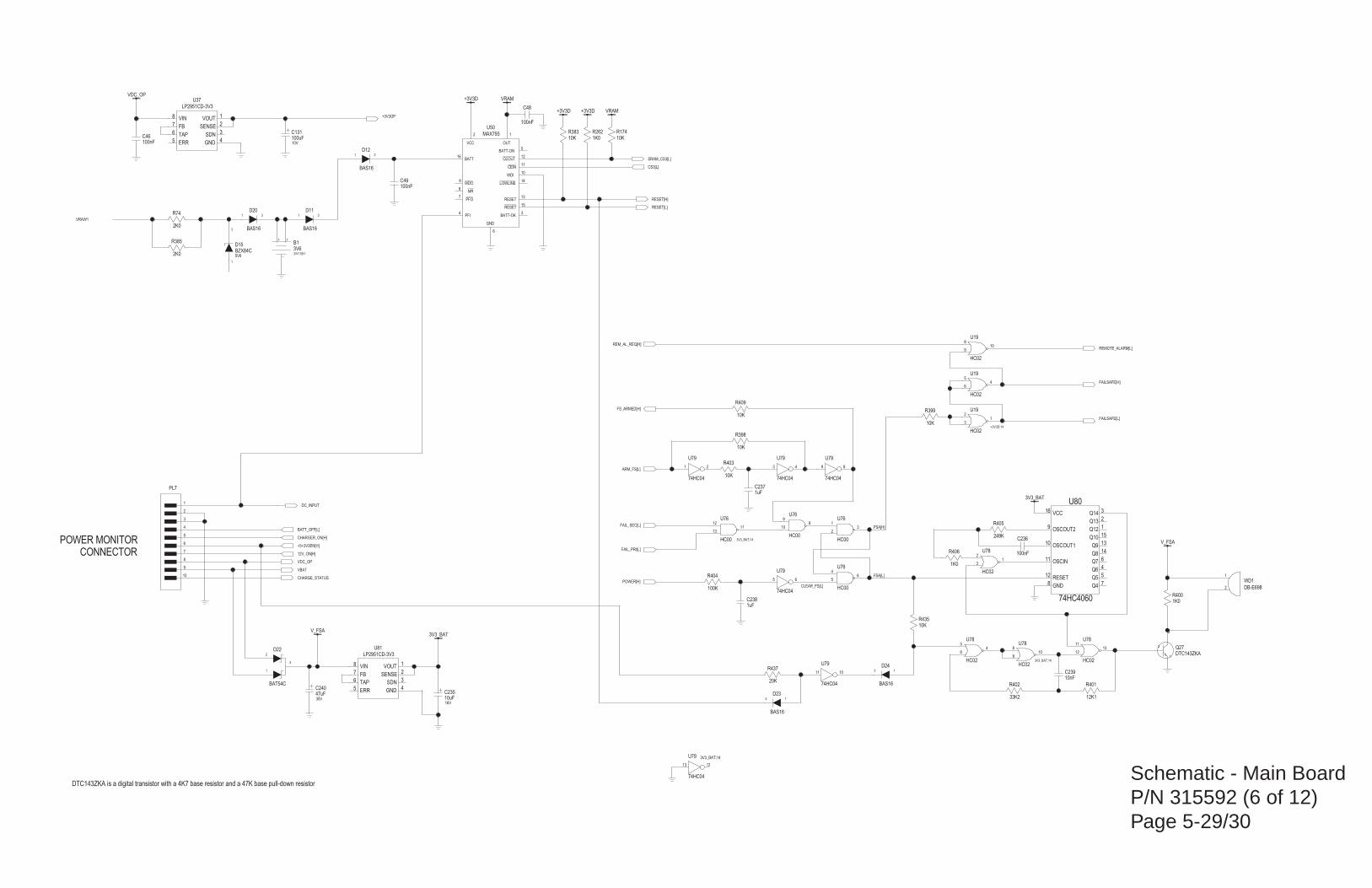
Schematic - Main BoardP/N 315592 (6 of 12)Page 5-29/30
10K
BAS16
10K
HC02
DTC143ZKA
10nF
10K
1uF
47uF35V
+3V3D+3V3D
+3V3D
100nF
100nF
VRAM
100nF
VRAM
MAX793
VCC OUT
BATT
WDO
MR
PFO
PFI
GND
BATT-ON
CEOUT
CEIN
WDI
LOWLINE
RESET
RESET
BATT-OK
BAS16
BZX84C5V6
10K
1uF
HC00
74HC04
HC00100K
74HC04
74HC04
HC00
100nF
VDC_OP
3V3_BAT
DB-E698
HC02
HC02
3/V110H
3V6
HC02HC02 HC02
HC02
10K
2K0
BAT54C
V_FSA
V_FSA
74HC04
3V3_BAT
33K2
HC00
1K0
249K
2K0
10uF16V
100uF10V
74HC04
GND
OSCIN
OSCOUT1
OSCOUT2
RESET
VCC
Q4
Q5
Q6
Q7
Q8
Q9
Q10
Q12
Q13
Q14
74HC4060
20K
1K0 10K
BAS16
74HC04
BAS16
BAS16
10K
LP2951CD-3V3
VOUT
SDN
GND
SENSE
VIN
FB
TAP
ERR
LP2951CD-3V3
VOUT
SDN
GND
SENSE
VIN
FB
TAP
ERR
1K0
12K1
CONNECTORPOWER MONITOR
DTC143ZKA is a digital transistor with a 4K7 base resistor and a 47K base pull-down resistor
R401
R400
5
6
7
8
2
4
3
1
U37
1
3
4
2
8
7
6
5
U81
R403
31
D12
1 3
D11
11 10
U79
+5+3V3EN[H]
13
D23
R174R262
R437
8
11
10
9
12
16
7
5
4
6
14
13
15
1
2
3
U80
1213
U79 3V3_BAT;14
C131
VRAW1
C235
R74
R405
R406
REMOTE_ALARM[L]
9
108
U76
R402
21
U79
3
1
2
D22
R385
CLEAR_FS[L]
FAILSAFE[H]
FS_ARMED[H]
R398
31
2U78
1113
12
U785
46
U78
910
8U78
3V3_BAT;14
B1
FAILSAFE[L]
REM_AL_REQ[H]
54
6
U19
31
2U19
+3V3D;14
1
2
WD1
C236
1113
12
3V3_BAT;14
U76
65
U79
FSA[H]
POWER[H]
FAIL_PRI[L]
FAIL_SEC[L]
ARM_FS[L]9 8
U79
R404 65
4U76
3 4
U79
1
23
U76
C237
RESET[L]
R383
1
3
D15
1 3
D20
1
2
3
4
5
6
7
8
9
10
PL7
CS3[L]
2 1
16
9
8
7
4
6
5
12
11
10
14
13
15
3
U50
C48
C46
C49
CHARGER_ON[H]
BATT_OFF[L]
CHARGE_STATUS
SRAM_CS3[L]
RESET[H]
C240
C238
R399
C239
1
2
3
Q27
810
9
U19
R409
DC_INPUT
VDC_OP
VBAT
13
D24
R435
12V_ON[H]
FSA[L]
+3V3OP

Schematic - Main BoardP/N 315592 (7 of 12)Page 5-31/32
2K0
0VITA
0VITA
DTC143ZKA
DTC143ZKA
0R0
0R0
PIC16C622A-20
RB7
RB6
RB5
CLKIN RA0
CLKOUT
VPP
T0CKI
RA1
RA2
RB1
VSS
RB0
RA3
RB4
RB3
RB2
VDD
100nF
47uF16V
68K1
5K76
3K091%
1K0
2K740.1%
1uF
100nF
0VITA
100nF
0VITA
+5VIT
BLM31B601S
BLM31B601S
10K
22K10.1%
+3V3D
0VITA
100nF
10K
+5VIT
0VITA
+5VIT
470R1%
4K99
0VITA0VITA
100nF10K
0VITA
7K87
100nF
0VITA
0VITA
+5VIT
4K320.1%
VREF
0VITA
2K71%
TL431
0VITA
+5VIT
0VIT
0VIT
15pF
15pF
0VIT
0VIT
0VIT
0VIT
10K
150R
+5VIT
0VIT
100nF
0VIT
0VITA
AD822AD822
7K87
47K1%
4N35
AN
CTH
C
B
E
0VITA0VITA
0VITA
VREF
MAX1241
DO
CS
SCLK
0VITA
22K10.1%
+5VIT
10K
10K
+5VIT
+5VIT
100nF
0VITA
+5VIT
19.6608MHz
0VIT
A0
A1
A2
E
Y0
Y1
Y2
Y3
Y4
Y5
Y6
Y7
VDD
VEE VSS
Z
HEF4051B
0VITA
0VITA
0VIT
VREF
1uF
+5VIT
10K
BLM31B601S
Z>200/100MHZ
0VITA
BLM31B601S
BLM31B601SZ>200/100MHZ
BLM31B601S
BLM31B601S
16K90.1%
ISOLATION BARRIER
Temp Probe 1
Temp probe 2
R79
5
6
4
3
2
1
SK4
L9
L6
18
7 2
3
4
6
5
FL7
5
6
4
3
2
1
SK3
L26
L5
5
6
4
3
27
8 1FL5
L12
R178
C137
11
10
9
6
13
14
15
12
1
5
2
4
16
7 8
3
U38
XL1
C54
R183
R180
R133
4
2
3
1
5
6
7
8
U2
1
2
5
6
4
U4
R50
R69
83
24
1
U605
6
7
U60
C50
R200
R177
C205
C204
TEMP_DATA[L]
2 3 6 7
1
8
U32 R197
R17
C51
R68
R179 C52
R316
R296
R181
C53
R134
R182
L1
L10
C55 C56
C138
R128
R325
R318
R45
R49
C187
C129
13
12
11
16 17
15
4
3
18
1
7
5
6
2
10
9
8
14
U43
R62
R63
2
1
3
Q28
3
1
2 Q29
R297

Schematic - Main BoardP/N 315592 (8 of 12)Page 5-33/34
SP
10K
HCT32
SI9956DY
10K
DTC143ZKA
1K0
10R
2R75%
1uF50V
1uF50V
PHT6N06LT
330pF
220uF25V
2u250V
2u250V
VIN VOUT
VSS
XC62FP5002PR
100nF2K71%
2K71%
750R
CEPH205
10uF20V
10uF20V
10uF20V
10uF20V
RB160L-40
RB160L-40
4N35
AN
CTH
C
B
E
4u7
4u7
220pF
39R1%
220pF
39R1%
10K0.1%
10K0.1%
10K
470pF
100nF
BZX84C5V1
330pF100pF
100nF
15K
30R1%
470pF
4u7
UCC3809D-1
FB
SS
RT1
RT2
REF
VDD
OUT
GND
SP
15K
100nF 100nF
10nF
10nF
VE
VO
GND
VCCAN
CTH
HCPL-2601
470R1%
PHT6N06T
VE
VO
GND
VCCAN
CTH
HCPL-260110K
DTC143ZKA
0.3A
1SMB5919BT35V6
HC02
100nF
+5VD
+5VD
470R1%
100nF
+3V3D
+5VD
33K2
470R1%
SI9956DY
HCT32
HCT32
HCT32
0R0
NF
CNY17F-3
AN
B
C
CTHE
750R
TL431
750R
SP
SP
10K
470R1%
2N7002
SP
750R
CONNECTOR
ISOLATION BARRIER
PROBE HOLDER
R438
+5VSPO2
1
2
3
Q37
FROM_SPO2_ISO
R21
R431
R4302 3 6 7
1
8
U16
R294
1
6
5
24
U5
VRAW1
ANA+
R426
R427
65
4U83
6
5
4
3
2
1
PL13
12
1311
U83
+5VD;14GND;7
1
23
U83
PG
1
2
7
8
Q32
R20
R303
FAILSAFE[L]
C234
R298
C233
1113
12+3V3D;14
U19
D18
FS1
FROM_SPO2
2
1
3
Q12
R299
7
6
5
82
3
U11
1
3
2
4
Q6
R300
7
6
5
82
3
U10
C145
C146
C98C100
R320
1
2
3
4
8
7
6
5
U69
L2
C168
R78
R319
C99
C92 C124
1
3
D16
C97
C167
R184
R54
R55
R8
C107
R9
C108
L3
L4
1
2
5
6
4
U6
D1
D2
C156 C157
C158 C159
11
12
7
8
5
2
1
6
T1
R295
R198 R199 C57
2 3
1
U52
+5VIT
0VIT
C141 C142C201
C123
1
3
2
4
Q15
C112 C113
R282
R3
R286
3
1
2 Q26
SPO2_RESET
TO_SPO2
R192
TO_SPO2_ISO
RESET_TO_SPO2_ISO
6
5
4
3
Q32
810
9U83
WARM_T
WARM_B R432
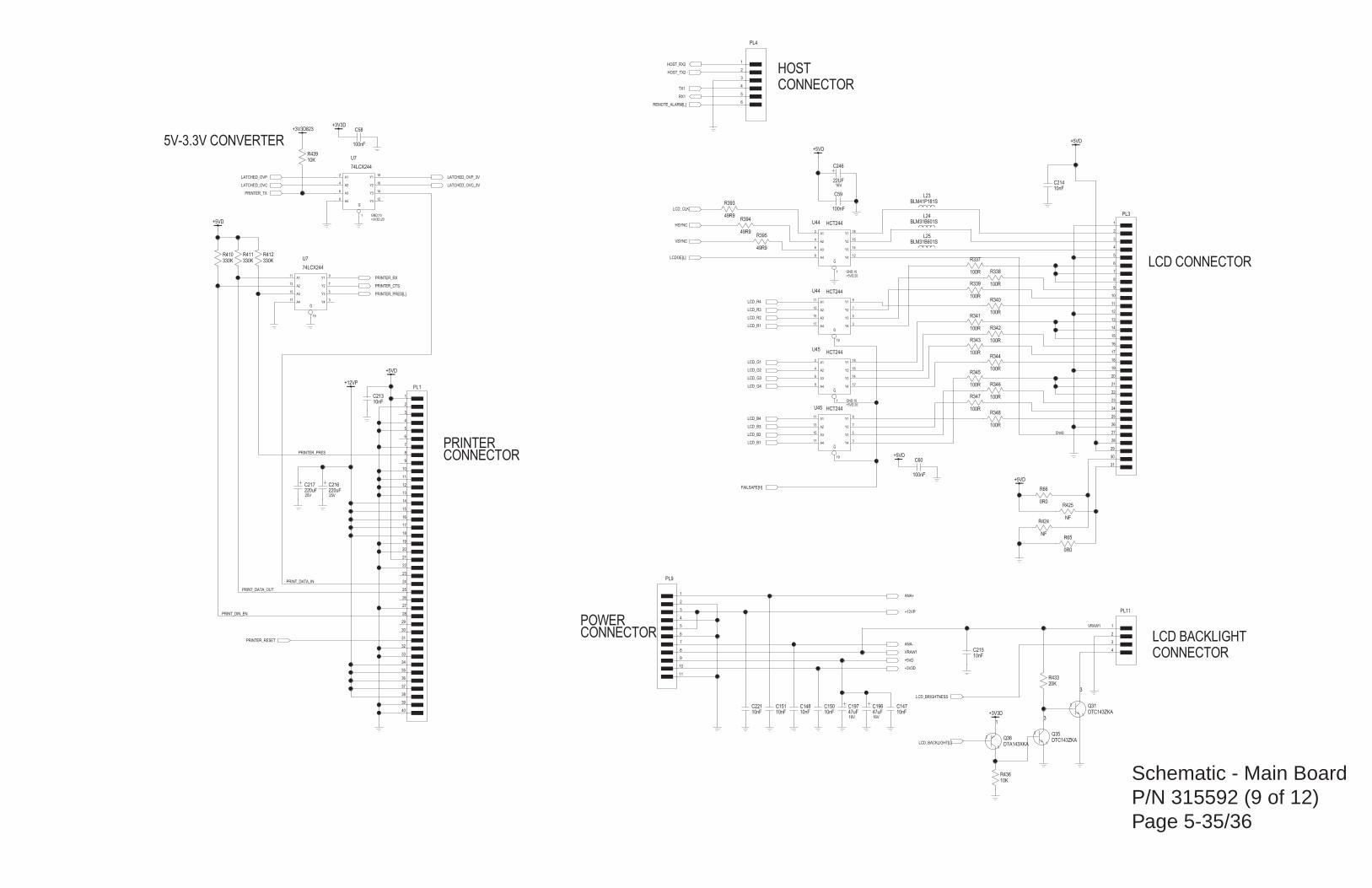
Schematic - Main BoardP/N 315592 (9 of 12)Page 5-35/36
+3V3D823
+3V3D
DTC143ZKA
20K
NF
330K
49R9
47uF16V
47uF16V
+12VP
10nF
10nF
10nF
220uF25V
220uF25V
100R
100R
100R
100R
100R
BLM31B601S
100nF
10nF10nF
+3V3D
+5VD
BLM31B601S
100R
100R
100R
100R
100R
100R
100R
10nF10nF
100nF
HCT244
G
A3
A2
A1
Y3
Y4
Y2
Y1
A4
HCT244
G
A3
A2
A1
Y3
Y4
Y2
Y1
A4
HCT244
G
A3
A2
A1
Y3
Y4
Y2
Y1
A4
HCT244
G
A3
A2
A1
Y3
Y4
Y2
Y1
A4
74LCX244
G
A3
A2
A1
Y3
Y4
Y2
Y1
A4
49R9
49R9
330K 330K
+5VD
10nF
74LCX244
G
A3
A2
A1
Y3
Y4
Y2
Y1
A4
+5VD
0R0
0R0
+5VD
NF
DTC143ZKA
+5VD
100nF
BLM41P181S
DTA143XKA
22UF16V
10K
10K
+5VD
HOSTCONNECTOR
PRINTER
POWER
LCD CONNECTOR
LCD BACKLIGHTCONNECTOR
CONNECTOR
CONNECTOR
5V-3.3V CONVERTERR439
R436
C246
1
2
3
Q36
L23C59
2
1
3
Q31
REMOTE_ALARM[L]
PRINT_DATA_IN
ENAB
R424
R66
R65
LCD_BRIGHTNESS
1
6
4
2
14
12
16
18
8
GND;10+3V3D;20
U7
FAILSAFE[H]
4
3
2
1
PL11
C151
PRINTER_PRES
PRINT_DATA_OUT
R412R411
LCD_CLK
HSYNC
VSYNC
R395
R3941
27
2
28
3
29
4
30
5
31
6
7
8
9
10
11
12
13
14
15
16
17
18
19
20
21
22
23
24
25
26
PL3
19
15
13
11
5
3
7
9
17
U7
19
15
13
11
5
3
7
9
17
U45
1
6
4
2
14
12
16
18
8
GND;10+5VD;20
U45
19
15
13
11
5
3
7
9
17
U44
1
6
4
2
14
12
16
18
8
GND;10+5VD;20
U44
C58
1
2
3
4
5
6
7
8
9
10
11
PL9
C221 C148
ANA-
+3V3D
ANA+
1
2
3
4
5
6
7
8
9
10
11
12
13
14
15
16
17
18
19
20
21
22
23
24
25
26
27
28
29
30
31
32
33
34
35
36
37
38
39
40
PL1
R338
R340
R342
R343
R341
R339
R337
L25
PRINTER_RESET
PRINTER_CTS
LCD_B1
LCD_B4
LCD_B3
LCD_B2
LCD_G4
LCD_G3
LCD_G2
LCD_G1
LCD_R4
LCD_R3
LCD_R2
LCD_R1
C150 C147
+5VD
C60
PRINTER_PRES[L]
L24
R344
R345
R346
R347
R348
C216C217
C213
C214
C215
+12VP
C196C197
LCDOE[L]
R393
R410
PRINT_DIN_EN
PRINTER_RX
LATCHED_OVP_3V
LATCHED_OVC_3VLATCHED_OVC
LATCHED_OVP
R425
6
5
4
3
2
1
PL4
HOST_RX2
TX1
HOST_TX2
RX1
R433
VRAW1
VRAW1
3
1
2 Q35
LCD_BACKLIGHT[L]
PRINTER_TX

Schematic - Main BoardP/N 315592 (11 of 12)Page 5-39/40
VDD
SP
0R0
47uF16V
47uF16V
47uF16V
23R-25MHz
SP
220uF16V
220uF16V
SP
10nF
10R
SP
BLM31B601S
VLED_SP
VDDA
SP
VDD
SP
SP
SP
100K
100nF
VDD
SP
820pF
1n53K15V
47uF16V
220uF10V
SP
10nF
22nF
100nF100nF100nF 100nF
10K5
39nF
10K
VDD
2K0
2K0
200R
200R
100nF
22nF
200R
4u716V
100pF
VDDA
2K0
100pF100pF
100nF
4u716V
22nF
1uF16V
49R9
2K0
VDD
499K
49K9
41K241K2
249K
249K
33K2
100R
100R
100K
10R
VLED_SP
BLM31B601S
BLM31B601S
BLM31B601S
BLM31B601S
BLM31B601S
BLM31B601S
Z>200/100MHZ
Z>200/100MHZ
SP
SP
SP
SP
SP
SP
SP
SP
SP
SP
SP
SP
SP
100nF
BLM31B601S
100nF
10R
VDD
20K
22nF
41K2 41K2
200R
15K8
15K8SP
100nF
SP
200R
TLC3704CD
1uF16V
4u716V
SP
200R
10nF
SPSP
470pF
OXICHIP2
26ZERO/TEST
3VREF5
VREF256
VCCA
19
VCC
20
V10
50
TESTFB51
STOUT23
STIN21
35SATIN-L
24RESET-L
13RED
11RDMGOUT
12
RDMGIN
RDMGC 10
53RCALTP
RCALOUT52
RCALFB56
57
RCAL-
58
RCAL+
PGAOUT7
30MODE
18LOWSIGC
LOWSIG25
44
LIMFLT
42
LIM
39LED-
38LED+
5ISET
14IR
IDMGOUT 16
IDMGIN
15
17IDMGC
GPTCLK29
GATE36
9FLTOUT
FLTIN 8
45ERROR
41
ENB+
DOUT
4
DKCAP63
DKAMPOUT59
DKAMPIN
61
DKAMPFB60
DIFFIN-
68
1
DIFFIN+
2 DIFFFB+
67 DIFF-
54
DGND
62DARK
DACLOAD31
32DACDATA
DACCLK33
CYCLE34
40CLL
37CHL
C2-49
C2+48
C1-47
C1+46
64ALCSW
66ALCOUT
65ALCIN
55
AGND
VPP22
28ADCCLK
ENLIMRST-L43
CLK10MH27
-
+
OUTIN
VREF25
VREF5
PGA
+
-
IN
CAP
OUTIN
IN
LEVEL SHIFTERS
DEMOD
-
+
-
+ I N
ALC
WINDOW
DRIVE
LED RCAL
+
-
TEST SW
CAP
OUT
REFERENCES
DOUBLER
SP
SP
Z>200/100MHZ
100nF
1n53K15V
VDDA
10K0.1%
SP
DARK
ISOLATION BARRIER
SPO2
CONNECTOR
R56
RESET_TO_SPO2_ISO
15
16
1
2
3
4
5
6
7
8
9
10
11
12
13
14
SK2
C230
C76
5
6
4
3
27
8 1
FL6
U9
C169
C154
R37
C200
C134
7
6
1
U21
R36
C80
R269
R268
R35
R132R131
C166
R265
R281
C79
L19
C78
3
1
2
4
FL2
3
1
2
4
FL1
L18
L17
L16
L15
L14
L13
R280
R327
R23
R22
R278
R288
R287
R130 R129
R82
R31
R104
R106
C133
C165
C199
C77
C95 C94
R103C93 C198
R34
C164
C75
R33
R32
R102
R101
R191
C114
R72
C182C181 C180 C179
C91
C188
ZERO/TEST
IDMGOUT
RDMGOUT
VREF25
VREF5
DACCLK
DACDATA
DACLOAD-L
MODE
LIM
RESET-OUT
RESET-OUT
ASIC-RESET-L
CLK10
SNSRDET-L
+2V5VREF
LOWSIG-L
VREF25
ISETDARK
ERROR-L
RCALOUT
VREF25
LOWSIG
C143
C175
C45
LED-
DET-CATHODE
INR-SHIELD
DET-ANODE
RCAL
RCAL
RCAL-RTN
RCAL-RTN
LED+
C139
C81
R326
L20
R279
C153
C128
C127
L21
C177 C178
C176R67
+5VSPO2
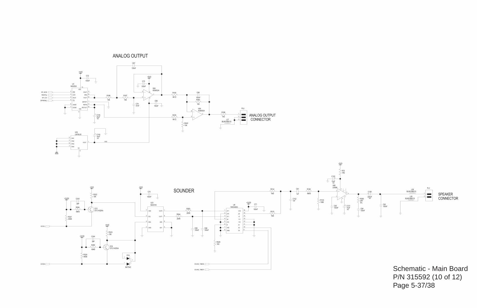
Schematic - Main BoardP/N 315592 (10 of 12)Page 5-37/38
BLM31B601S
10K
1K0
39P
1nF 2R75%
100nF
100nF
100nF
MAX518
VDD
SCL
SDA
GND
OUT0
OUT1
AD0
AD1
BAT54C
+5VD
15K
DTC143ZKA
+5VD
15K
DTC143ZKA
ANA-
LM79L05
VOUT
G3
VIN1
VIN2
VIN3
VIN4
100nF
10uF16V
10uF16V
220uF16V
+5VD
LM386
100nF
100nF 100nF
MAX504
DOUT
VSS
REFIN
VOUT
CS
SCLK
CLR
DIN
DGND
AGND
BIPOFF
REFOUT
VDD
RFB
74HC4053
S1
1Y0
S2
3Y0
E
VEE
GND
1Y1
2Z
2Y1
3Y1
3Z
VCC
1Z
S3
2Y0
AD8052A
+5VD
+5VD
+3V3D
+5VD
100nF
33uF16V
AD8052A
1R0
100nF
15K 15K
10K
100nF
1K0
4K12
47nF
10uF16V
100nF100nF
200K
200K
1M0
1M0
158K
1nF 49K9
4K99
4K99
49K9
49K9
39P
+3V3D
+3V3D
BLM31B601S
4K12
BLM31B601S
CONNECTOR
SOUNDER
ANALOG OUTPUT
ANALOG OUTPUT
SPEAKERCONNECTOR
L29
R190
L27
C243
R284
R285
R321
R324
SOUND_TIMER1
SOUND_TIMER2
R185C61
R100
R314
R315
R263
R264
-5VD
C62C63
C155
C74
3
2
1
PL5
R376
R188
C68
R382
R187R186
C69
R75
7
6
5
U64
C105
C70
I2CSCL
DEFIBEN[L]
8
4
1
3
2
U64
11
12
10
5
6
7
8
13
15
1
3
4
16
14
9
2
U8
6
11
9
12
5
4
3
2
7
8
1
10
13
14
U3
C66C65
C64
2
1
PL2
2
6
1
8
4
7
5
3
U68
C126
C122
C121
C67
RESET[L]
5
2
3
6
7
1
U34
SPI_CLK
SPI_MOSI
2
1
3
Q13
R322
2
1
3
Q14
R323
2
1
3
D14
I2CSDA
7
3
4
2
1
8
6
5
U23C71
C72
C73
R283C152
C244
R429
R440
L28
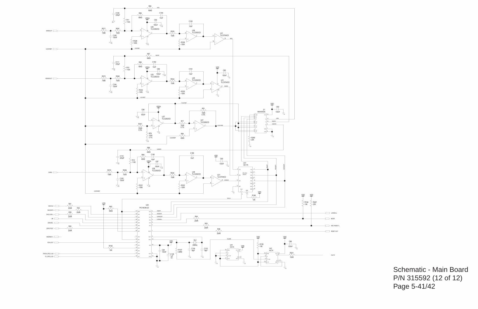
Schematic - Main BoardP/N 315592 (12 of 12)Page 5-41/42
10K
20MHz
150K0.5%
53K60.5%
VDD
49K9
10nF10nF
100nF
100nF
10nF
10nF
10nF
10nF
100nF
162K
162K
162K
110K
110K
110K
158K
158K
158K
220pF
100K
100K
VDDA
TLC2262CD
TLC2262CD
TLC2262CD
100nF
20K49K9
VDDA
TLC2262CD
100K0.1%
100nF
100K
49K9
HC74
Q
VCC
GND
Q
PRE
D
CLK
CLR
150R
VDD
18pF100nF
20K
SP
SPSP
SP
SP
SP
SP
SP
100nF
SP
SP
SP
SP
SP
VDD
SP
SP
SP
SP
200R
200R
200R
200R
1uF16V
SP
18pF
100nF
VDD
SP
10K
SP
SP
49K9
SPSP
100K 100K
TLC2262CD
TLC2262CD
TLC3704CD
SP100nFSP
220pF
SP
SP
VDDA
100K0.1%
TLC2262CD
VDD
100nF
SP
49K9
100K
TLC2262CD
TLC3704CD
VDDA
100K
100K
100K
49K9
49K9
49K9
100nF
220pF
SP
100nF
200R
VDDVDD
TLC3704CD
VDD
VDD
49R9
VDD
10K
HC74
Q
VCC
GND
Q
PRE
D
CLK
CLR
VDD;16
HC175
4Q
3Q
2Q
1Q
CLRCLK
1Q
2Q
3Q
4Q4D
3D
2D
1D
SP_DG;8
A
B
C
INH VCC
VEE
VSS
X
X1
XO Y
Y0
Y1
Z
Z0
Z1
MAX4053A
MCLR
VDD
VSS1
OSC1
RA5
RA4
RA3
RA2
RA1
RA0
RC6
RC5
RC4
RC3
RC2
RC1
RC0
RB7
RB6
RB5
RB4
RB3
RB2
VSS2RC7
RB1
RB0
OSC2
PIC16C66-20
200R
200R
VDD
10K
SDCLK
IRSDFF
IRSDFF
DARKSDFF
DARKSDFF
REDSDFF
REDSDFF
IRFB
IRFB
R193
RESET-OUT
CLK10
R38
R42
SNSRDET-L
1
20
8
9
7
6
5
4
3
2
17
16
15
14
13
12
11
28
27
26
25
24
23
1918
22
21
10
U22
11109
6 1 6
7
8
14
1312 15
21
4
53
U1
14
11
6
3
19
2
7
10
1513
12
5
4
U31
6
14
7
54
2
3
1
U41
R194
CLK20
R107
35
412
2
U21
R44
C90
C111
C89
R90
R89
R88
R336
R335
R334
11
10
13
U21
8
4
1
2
3
U26
R333
R87
C88
8
4
1
2
3
U27
R77
C110
C87
9
8
14
U21
8
4
1
2
3
U28
7
6
5
U28
R332R331
R86
R195
C86
C104
C135
R43
R41
R40
R39
C85
R267
C84C103
R201
8
14
7
910
12
11
13
U41
R85
R330
C83
R76
7
6
5
U27
R84
R266
C82
7
6
5
U26
7
6
5
U258
4
1
2
3
U25
R329
R328
C109
R272
R271
R270
R12
R11
R10
R291
R290
R289
C185
C194
C193
C192
C191
C184
C183
C190C189
R83
R301
R51
XL3
+3V81VREF
MODE
ASIC-RESET-L
DARK
+1V63VREF
TO_SPO2_ISO
RCALOUT
LOWSIG-L
LOWSIG-L
IDMGOUT
RDMGOUT
IRSD
REDSD
+2V5VREF
+2V5VREF
+2V5VREF
+2V5VREF+2V5VREF
ZERO/TEST
ERROR-L
DACDATA
LIM
REDFB
REDFB
DARKFB
DARKFB
DACCLK
DACLOAD-L
DARKSD
R196
FROM_SPO2_ISO
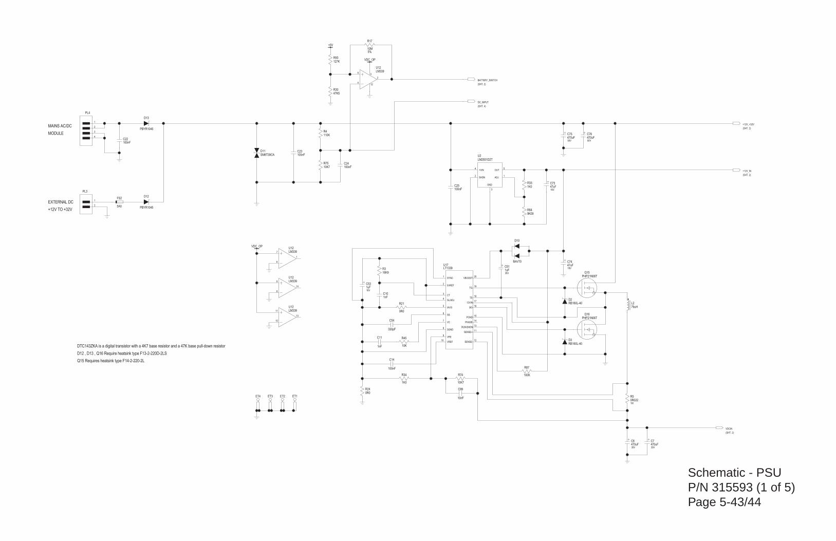
Schematic - PSUP/N 315593 (1 of 5)Page 5-43/44
47K5
127K
10nF
330pF
0R0221W
0R0
VDC_OP
+5V
0R0
470uF35V
470uF35V
79uH
PHP21N06T
PHP21N06T
RB160L-40
1K0
1uF16V
1nF
47uF16V
470uF50V
470uF50V
9K09
1K0100nF
10M5%
110K
100nFSM6T39CA
10K7 100nF
16K9
10K1nF
100nF
10K7
1uF35V
47uF16V
100K
LM339
100nF
PBYR1045
PBYR1045
LM339
LM339
LM339
VDC_OP
LM2931D2T
SHDN
+VIN
GND
OUT
ADJ
LT1339
SENSE-
SENSE+
RUN/SHDN
PHASE
PGND
BG
12VIN
TS
SGND
SYNC
VREF
VFB
VC
SS
IAVG
5VREF
CT
SL/ADJ
VBOOST
TG
BAV70
RB160L-40
(SHT. 2)
(SHT. 2)
(SHT. 2)MAINS AC/DC
MODULE
EXTERNAL DC
+12V TO +32V
(SHT. 2)
(SHT. 4)
DTC143ZKA is a digital transistor with a 4K7 base resistor and a 47K base pull-down resistor
D12 , D13 , Q16 Require heatsink type F13-2-220D-2LS
Q15 Requires heatsink type F14-2-220-2L
5A0
ET2ET4
FS2
VDCIN
D2
+12V_IN
D10
12
11
13
14
15
16
17
18
8
1
10
9
7
6
5
2
3
4
20
19
U17
2
4
3
5
1
U2
+12V_+32V
9
8
14
U12
11
10
13
U12
7
6
1
U12
BATTERY_SWITCH
D12
D13
C22
35
412
2
U12
DC_INPUT
R87
C74
C51
R74
C14
C11 R45
R3
C24R75
D11 C23
R4
R17
C25R33
R64
C75 C76
C73
C10
C53
R34
D3
Q15
Q16
L2
C6 C7
R24
ET3 ET1
R21
R5
2
1
PL3
2
1
3
4
PL4
C54
C99
R93
R30
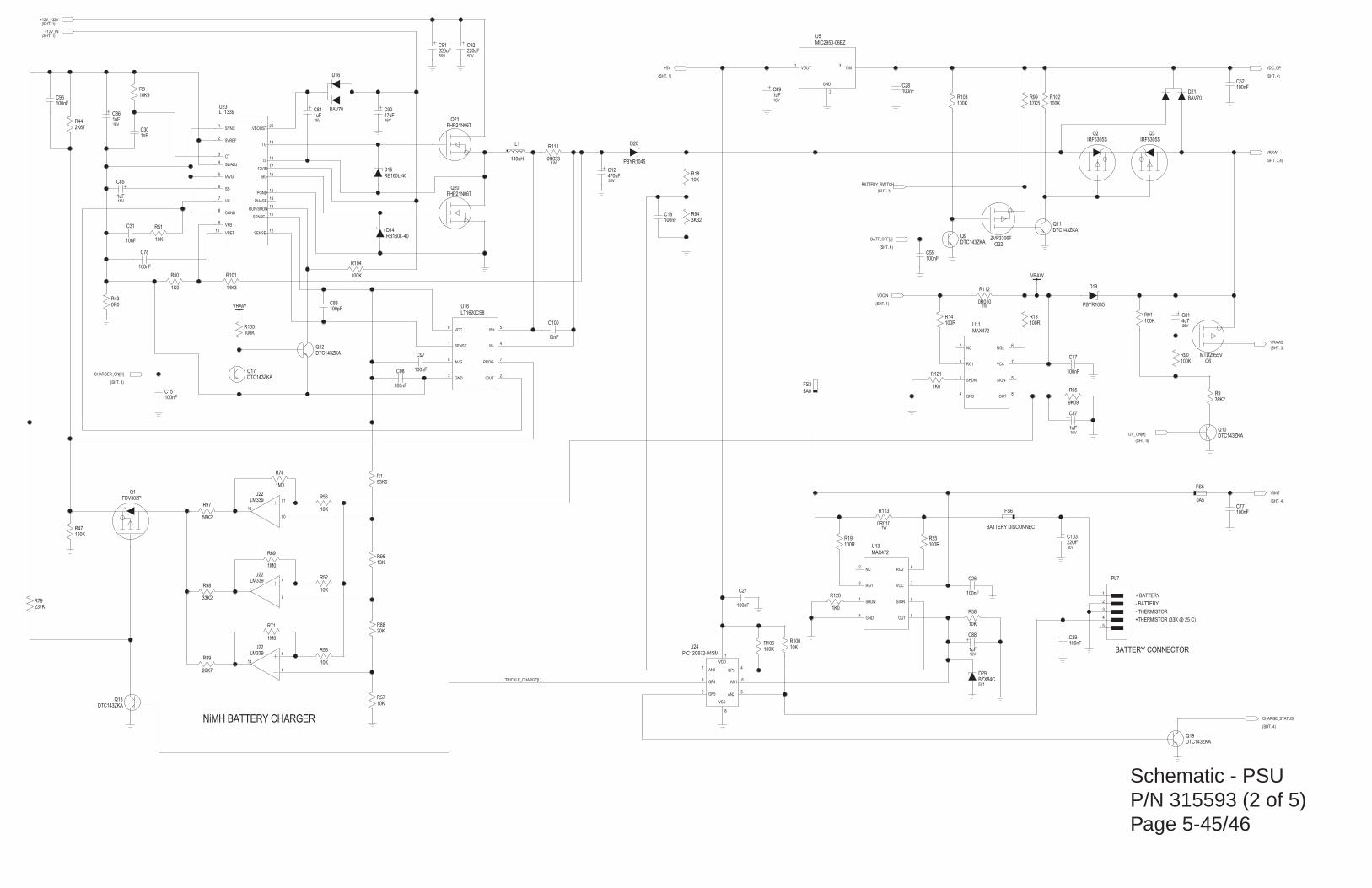
Schematic - PSUP/N 315593 (2 of 5)Page 5-45/46
1K0
9K09
56K2
26K7
33K2
150K
100nF
100pF
10nF
100nF
100nF
100nF
100nF
100nF
100nF
3K32
10K
0R0101W
0R0101W
0R0331W
39K2
4u735V
100K
DTC143ZKA
220uF50V
220uF50V
53K6
VRAW
MIC2950-06BZ
GND
VOUT VIN
100K
10K
1uF16V
MAX472
NC
RG1
SHDN
GND
RG2
VCC
SIGN
OUT
100R 100R
DTC143ZKA
PBYR1045
470uF35V
1uF16V
10K
1M0
10K
10K
LM339
100K
DTC143ZKA
0R0
PHP21N06T
PHP21N06T
RB160L-40
1uF16V
10K
1uF35V
47uF16V
RB160L-40
100K
IRF5305S
100nF
DTC143ZKA
100nF
IRF5305S
100KBAV70
DTC143ZKA
47K5
1nF
16K9
14K3
100nF
1K0
1M0
1M0
20K
13K
10K
100R 100R
FDV302P
DTC143ZKA
DTC143ZKA
1uF16V
VRAW
149uH
MAX472
NC
RG1
SHDN
GND
RG2
VCC
SIGN
OUT
LM339
LM339
LT1339
SENSE-
SENSE+
RUN/SHDN
PHASE
PGND
BG
12VIN
TS
SGND
SYNC
VREF
VFB
VC
SS
IAVG
5VREF
CT
SL/ADJ
VBOOST
TG
100nF
2K67
BAV70
100K
10nF
100nF
LT1620CS8
VCC
SENSE
AVG
GND
IN+
IN-
PROG
IOUT
1uF16V
100K
MTD2955V
PBYR1045
PIC12C672-04SM
AN0
AN1
AN2
GP3
GP4
GP5
VDD
VSS
100nF10K
0A5
ZVP3306F
100nF
237K
BZX84C5V1
22UF50V
1K0
BATTERY CONNECTOR
(SHT. 3)
(SHT. 4)
(SHT. 4)
(SHT. 4)
(SHT. 4)
(SHT. 3,4)
(SHT. 4)
(SHT. 4)
(SHT. 1)
(SHT. 1)
(SHT. 1)
(SHT. 1)
5A0
NiMH BATTERY CHARGER
BATTERY DISCONNECT
(SHT. 1)
+THERMISTOR (33K @ 25 C)
- THERMISTOR
+ BATTERY
- BATTERY
R120
12V_ON[H]
C103
D29
R79
C55
Q22
FS5
FS3
FS6
R100C29
TRICKLE_CHARGE[L]
7
6
5
4
3
2
1
8
U24
VBAT
D19
Q6
R91
C85
6
1
8
3
5
4
7
2
U16
C97
C100
+12V_IN
R104
D16
R44
C96
12
11
13
14
15
16
17
18
8
1
10
9
7
6
5
2
3
4
20
19
U23
11
10
13
U22
7
6
1
U22
2
3
1
4
6
7
5
8
U11
L1
+12V_+32V
CHARGER_ON[H]
C89
CHARGE_STATUS
Q18
Q17
Q1
R13R14
R57
R96
R88
R78
R69
R50
C78
R101
R8
C30
R99
Q11
D21R103
Q3
C77
Q9
C52
Q2
R102
BATT_OFF[L]
VDC_OP
D15
C90C84
R51
C86
D14
Q21
Q20
R43
Q12
R105
9
8
14
U22
R52
R55
R71
R56
C87
C12
D20
Q19
R25R19
2
3
1
4
6
7
5
8
U13
C88
R58
R106
2
1 3
U5
R1
C91 C92
Q10
R90
C81
R9
R111
R112
R113
R18
R94
C15
C17
C18
C26
C27
C28
C31
C83
C98
R47
R98
R89
R97
R95
2
1
3
4
5
PL7
VRAW2
VDCIN
VRAW1
+5V
BATTERY_SWITCH
R121

Schematic - PSUP/N 315593 (3 of 5)Page 5-47/48
49R9
10K
0A5
12K1
220nF
220nF
220nF
0R0221W
0R0470.25W
100nF
RB160L-40100uF25V
100uH
2n2
1K21 13K
47K5
47K5
100nF100uF50V
NC=1
PBYR745B
330uF25V
210K
24K32n2
330uF25V
330uF25V
100nF
100nF
1uF16V FB
FREQ CS+
EXT
GND
MAX668
VCC SHDN
REF
LDO
PGND
100nF
100nF330uF25V
127K
RB051L-40
100nF
1uF16V
330uF25V
PHT6N06LT
330uF25V
330uF25V
RB160L-40
RB160L-40
100nF
LM2594
+VIN
FB
OUT
GNDON /OFF
33uH
12uH
LM340-12
GND
VIN VOUT
49R9
330uF25V
49R9 PHT11N06LT
237K
237K
TL431
FB
FREQ CS+
EXT
GND
MAX668
VCC SHDN
REF
LDO
PGND
100nF 330uF25V
49R9
4n7
100nF
LM324A
LM324A1K0
1K0
100K
0A5
PHT6N06LT
100nF
4u735V
100nF
G25C5%0
LM324A
LM324A
VRAW1
BAV70
LM339
20K20K20K
20K
20K
53K6
53K6150K
150K
20K
100K24K3
100K
FAN
(SHT. 4)
(SHT. 4)
(SHT. 4)
(SHT. 5)
(SHT. 5)
(SHT. 2)
(SHT. 2)
AUX 12V
ANA+
ANA-
+12V PRINTER SUPPLY
FAN CONTROL
VRAW1
R11
R68R12
R59
R60
R109R61
R63
R62
R110
R66 R48 R108
35
412
2
U22
D33
7
6
5
U21
8
9
10
U21
TH1
C101
2
1
PL6
C102
C82
Q8
FS8
R107
R115
R49
14
13
12
U21
4
1
11
2
3
U21
C16
C80
R22
C69C37
5
2 6
8
3
9 10
4
1
7
U8
2 3 6 7
1
8
U14
R67
R28
Q5R118
C70
R23
ANA+
ANA+
2
1 3
U10
L3
L4
7
4
8
65
U19
AUX_12V[F]
C35
ANA-
D5
D4
C71C63
Q7
C67
C56
C36
D7
R20
C68 C38
C32
5
2 6
8
3
9 10
4
1
7
U9
C57
C40
C39C64 C65
C3 R2
R7
C66
D17
C9 C33
R80
R81
R70R15
C4
L7
C13 D6
C34
R31
R6
C48
C46
C47
R65
AUX_12V
+12VP
FS1
R117
VRAW2
R119

Schematic - PSUP/N 315593 (4 of 5)Page 5-49/50
324R 1K07
100uH
220uF25V
10nF
562R
LM2595
ONGND
+VIN
FB
OUT
/OFF
100nF
DTC143ZKA
100nF
RB051L-4047K5
332R
100nF470uF25V
DTC143ZKA
470uF35V
100nF
LM2596
ONGND
+VIN
FB
OUT
/OFF
RB051L-4047K5
2n2
47uH
220uF25V
0A9
+3V3D SUPPLY
+5VD SUPPLY
CONNECTOR
POWER
POWER MONITOR
CONNECTOR
(SHT. 5)
(SHT. 5)
(SHT. 5)
U6 Requires heatsink type F14-2-220-2L
(SHT. 2)
FS4
VRAW1
VRAW1
+5+3V3EN[H]
+3V3D
12V_ON[H]
ANA+
C1
AUX_5V[F]
L5
C5
R82 D953
1
4
2
U6
C41C8
Q13
C79 C42
R73
R83 D8
C44
Q14
C43
53
2
4
1
U3
R10
C72
C2
+12VP
ANA-
DC_INPUT
CHARGER_ON[H]
BATT_OFF[L]
VDC_OP
VBAT
CHARGE_STATUS
L6
9
8
7
6
5
4
3
2
1
10
11
PL2
9
8
7
6
5
4
3
2
1
10
PL1
R16+5VD
R72
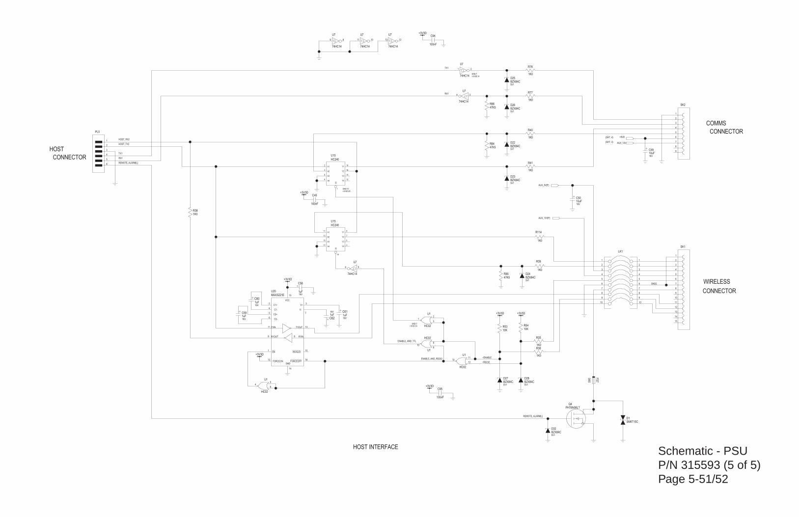
Schematic - PSUP/N 315593 (5 of 5)Page 5-51/52
+3V3D
100nF
+3V3D
100nF
1K0
SM6T15C
10K
+3V3D
100nF
47K5
+3V3D
1uF16V
1K0
1K0
47K5
+3V3D +3V3D1uF16V
1uF16V
1uF16V
1uF16V
10uF16V
10uF16V
C1+
C1-
C2+
C2-
FORCEONGND
R1INR1OUT
T1IN T1OUT
V+
V-
VCC
EN
FORCEOFF
INVALID
MAX3221E
+3V3D
1K0
HC240
Y1
Y2
Y3
Y4A4
A3
A2
A1
G
74HC14
74HC14
74HC14 74HC14 74HC14
74HC14
HC02
HC02
HC02
10K
HC02
47K5
1K0
1K0
1K0
1K0
1K0
0A5
HC240
Y1
Y2
Y3
Y4A4
A3
A2
A1
G
PHT6N06LT
BZX84C5V1
BZX84C5V1
BZX84C5V1
BZX84C5V1
BZX84C5V1
BZX84C5V1
BZX84C5V1
BZX84C5V1
(SHT. 4)
CONNECTOR
WIRELESS
CONNECTOR
CONNECTOR
COMMS
HOST
(SHT. 3)
HOST INTERFACE
4
3
2
1
6
7
5
9
10
8
4
3
2
1
6
7
5
9
10
8
LK1
D32
D27 D28
D24
D23
D22
D26
D25
Q4
~ENABLE
9
7
5
317
15
13
11
19
U15
FS7
HOST_TX2
~RS232
ENABLE_AND_RS232
ENABLE_AND_TTL
R38
RX1
RX1
AUX_5V[F]
AUX_12V[F]
R36
R35
R114
R39
R85
64
5U1
R53
31
2U1
+3V3D;14GND;7
910
8U1
HOST_RX2
1213
11U1
34
U7
13 12
U7
11 10
U7
9 8
U7
56
U7
1 2
U7
+3V3D;14GND;7
18
16
14
128
6
4
2
1
U15
+3V3D;20GND;10
R76
5
6
7
8
9
10
11
12
13
2
3
4
1
14
15
SK1
15
14
11 13
9 8
1
12 16
10
2
4
5
6
7
3
U20
C50
C49
C62
C61
C60
C59
R84
R41
R40
C58
R86
C45
R54
D1
5
6
7
8
9
2
3
4
1
SK2
R77
C94
C95
1
2
3
4
5
6
PL5
+5VD
AUX_12V
GND2
TX1
TX1
REMOTE_ALARM[L]
REMOTE_ALARM[L]
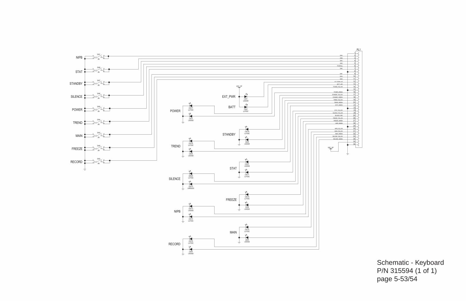
Schematic - KeyboardP/N 315594 (1 of 1)page 5-53/54
5N
A
A' B'
B
5N
A
A' B'
B
5N
A
A' B'
B
5N
A
A' B'
B
5N
A
A' B'
B
5N
A
A' B'
B
5N
A
A' B'
B
5N
A
A' B'
B
5N
A
A' B'
B
LUY53C
LUY53C
LUY53C
LUY53C
LUY53C
LUY53C
VDC_OP
LUY53C
LMR53DG
VDC_OP
LUY53C
LSG53D
LUY53C
LSG53D
LSG53D
LSG53D
LSG53D
LSG53D
LSG53D
LSG53D
LUY53C
LSG53D
NIPB
STAT
STANDBY
SILENCE
POWER
TREND
MAIN
FREEZE
STAT
RECORD
POWER
TREND
SILENCE
NIPB
RECORD
MAIN
FREEZE
STANDBY
BATT
EXT_PWR
LED21
LED11
LED9
LED1
LED4
LED5
LED6
LED3
LED8
LED12
LED13
LED2
POWER_YELLOW
RECORD_GREEN
RECORD_YELLOW
MAIN_GREEN
MAIN_YELLOW
NIPB_YELLOW
NIPB_GREEN
FREEZE_GREEN
FREEZE_YELLOW
SILENCE_RED
SILENCE_YELLOW
STAT_YELLOW
STAT_GREEN
TREND_GREEN
TREND_YELLOW
STANDBY_GREEN
STANDBY_YELLOW
POWER_GREEN
BATT_LED
EXT_POWER_LED
SWH
SWG
SWF
SWE
POWER[L]
SWD
SWC
SWB
SWA
5
6
7
8
9
10
11
12
13
3
4
14
15
16
17
18
19
20
21
23
24
25
28
29
30
31
22
1
2
26
27
32
33
34
35
36
PL1
LED10
LED17
LED18
LED19
LED20
LED14
LED15
LED16
SW1
SW8
SW7
SW6
SW5
SW4
SW3
SW9
SW2
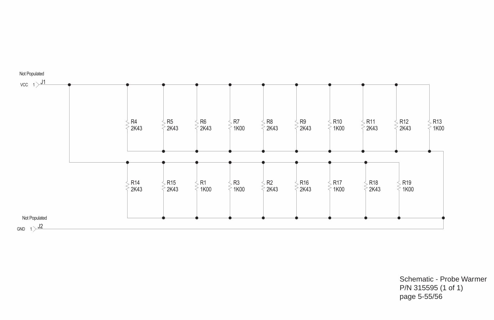
Schematic - Probe WarmerP/N 315595 (1 of 1)page 5-55/56
R13R12R11R10R8R7R6
R14
R9
R18R17R2R3
J11VCC
R19
R5
R16
R4
R1
J21GND
R15
1K002K432K431K002K431K002K43
2K43
2K43
2K431K002K431K00 1K00
2K43
2K43
2K43
1K002K43
Not Populated
Not Populated