pro tools 5.1 reference guide - digidesign support...
TRANSCRIPT
Pro ToolsReference Guide
Version 5.1 for Macintosh and Windows
Digidesign Inc.3401-A Hillview Avenue
Palo Alto, CA 94304 USAtel: 650·842·7900fax: 650·842·7999
Technical Support (USA)650·842·6699650·856·4275
Product Information (USA)650·842·6602800·333·2137
Fax on Demand (USA)1·888·USE·DIGI (873·3444)
International OfficesVisit the Digidesign Web site
for contact information.
World Wide Webwww.digidesign.com
Digidesign FTP Siteftp.digidesign.com
Copyright
This User’s Guide is copyrighted ©2001 by Digidesign, a division of Avid Technology, Inc. (hereafter “Digidesign”), with all rights reserved. Under copyright laws, this manual may not be duplicated in whole or in part without the written consent of Digidesign.
DIGIDESIGN, AVID and PRO TOOLS are trademarks or registered trademarks of Digidesign and/or Avid Technology, Inc. All other trademarks are the property of their respective owners.
All features and specifications subject to change without notice.
PN 932708437-00 REV A 01/01
Contents
Part I Introduction
Chapter 1. Welcome to Pro Tools . . . . . . . . . . . . . . . . . . . . . . . . . . . . . . . . . . . . . . . . . . . . . 3
The Pro Tools Guides . . . . . . . . . . . . . . . . . . . . . . . . . . . . . . . . . . . . . . . . . . . . . . . . . . . . . . 3
Compatibility Information. . . . . . . . . . . . . . . . . . . . . . . . . . . . . . . . . . . . . . . . . . . . . . . . . . . 4
Digidesign Registration . . . . . . . . . . . . . . . . . . . . . . . . . . . . . . . . . . . . . . . . . . . . . . . . . . . . 4
Chapter 2. Pro Tools System Configurations . . . . . . . . . . . . . . . . . . . . . . . . . . . . . . . . . . . 5
TDM-equipped systems . . . . . . . . . . . . . . . . . . . . . . . . . . . . . . . . . . . . . . . . . . . . . . . . . . . . 5
TDM System Playback, Recording and Voice Limits . . . . . . . . . . . . . . . . . . . . . . . . . . . . . . . . 6
Audio Interfaces for TDM Systems . . . . . . . . . . . . . . . . . . . . . . . . . . . . . . . . . . . . . . . . . . . . 6
Pro Tools LE Systems . . . . . . . . . . . . . . . . . . . . . . . . . . . . . . . . . . . . . . . . . . . . . . . . . . . . . 7
Pro Tools LE System Capabilities . . . . . . . . . . . . . . . . . . . . . . . . . . . . . . . . . . . . . . . . . . . . . 7
Chapter 3. Pro Tools Concepts. . . . . . . . . . . . . . . . . . . . . . . . . . . . . . . . . . . . . . . . . . . . . . . . 9
Hard Disk Recording . . . . . . . . . . . . . . . . . . . . . . . . . . . . . . . . . . . . . . . . . . . . . . . . . . . . . . 9
The Digidesign Audio Engine . . . . . . . . . . . . . . . . . . . . . . . . . . . . . . . . . . . . . . . . . . . . . . . . 9
Pro Tools Sessions and Concepts . . . . . . . . . . . . . . . . . . . . . . . . . . . . . . . . . . . . . . . . . . . . 10
System Resources. . . . . . . . . . . . . . . . . . . . . . . . . . . . . . . . . . . . . . . . . . . . . . . . . . . . . . . 13
MIDI Concepts . . . . . . . . . . . . . . . . . . . . . . . . . . . . . . . . . . . . . . . . . . . . . . . . . . . . . . . . . 15
Chapter 4. Pro Tools Windows . . . . . . . . . . . . . . . . . . . . . . . . . . . . . . . . . . . . . . . . . . . . . . . 17
The Mix Window . . . . . . . . . . . . . . . . . . . . . . . . . . . . . . . . . . . . . . . . . . . . . . . . . . . . . . . . 17
The Edit Window . . . . . . . . . . . . . . . . . . . . . . . . . . . . . . . . . . . . . . . . . . . . . . . . . . . . . . . . 25
The Transport Window . . . . . . . . . . . . . . . . . . . . . . . . . . . . . . . . . . . . . . . . . . . . . . . . . . . . 36
Contents iii
iv
Chapter 5. Keyboard Shortcuts . . . . . . . . . . . . . . . . . . . . . . . . . . . . . . . . . . . . . . . . . . . . . . 39
Global Key Commands . . . . . . . . . . . . . . . . . . . . . . . . . . . . . . . . . . . . . . . . . . . . . . . . . . . 39
Keyboard Focus . . . . . . . . . . . . . . . . . . . . . . . . . . . . . . . . . . . . . . . . . . . . . . . . . . . . . . . . 40
Numeric Keypad Modes . . . . . . . . . . . . . . . . . . . . . . . . . . . . . . . . . . . . . . . . . . . . . . . . . . 41
Part II Sessions & Tracks
Chapter 6. Sessions . . . . . . . . . . . . . . . . . . . . . . . . . . . . . . . . . . . . . . . . . . . . . . . . . . . . . . . . 45
Starting Up Your System . . . . . . . . . . . . . . . . . . . . . . . . . . . . . . . . . . . . . . . . . . . . . . . . . . 45
Configuring Your System . . . . . . . . . . . . . . . . . . . . . . . . . . . . . . . . . . . . . . . . . . . . . . . . . . 45
Changing the Pro Tools Playback Engine . . . . . . . . . . . . . . . . . . . . . . . . . . . . . . . . . . . . . . 48
Changing DAE Playback Buffer Size . . . . . . . . . . . . . . . . . . . . . . . . . . . . . . . . . . . . . . . . . . 49
Creating a New Session . . . . . . . . . . . . . . . . . . . . . . . . . . . . . . . . . . . . . . . . . . . . . . . . . . 50
Opening a Session . . . . . . . . . . . . . . . . . . . . . . . . . . . . . . . . . . . . . . . . . . . . . . . . . . . . . . 51
Saving a Session . . . . . . . . . . . . . . . . . . . . . . . . . . . . . . . . . . . . . . . . . . . . . . . . . . . . . . . 52
Creating Custom Session Templates . . . . . . . . . . . . . . . . . . . . . . . . . . . . . . . . . . . . . . . . . 55
Closing a Session . . . . . . . . . . . . . . . . . . . . . . . . . . . . . . . . . . . . . . . . . . . . . . . . . . . . . . . 56
Quitting Pro Tools . . . . . . . . . . . . . . . . . . . . . . . . . . . . . . . . . . . . . . . . . . . . . . . . . . . . . . . 56
Sharing Sessions between Pro Tools TDM Systems and Pro Tools LE Systems . . . . . . . . . . . . 57
Chapter 7. I/O Setup . . . . . . . . . . . . . . . . . . . . . . . . . . . . . . . . . . . . . . . . . . . . . . . . . . . . . . . 59
Understanding Paths and I/O Setup . . . . . . . . . . . . . . . . . . . . . . . . . . . . . . . . . . . . . . . . . . 59
The I/O Setup Dialog . . . . . . . . . . . . . . . . . . . . . . . . . . . . . . . . . . . . . . . . . . . . . . . . . . . . 62
Creating and Editing Paths . . . . . . . . . . . . . . . . . . . . . . . . . . . . . . . . . . . . . . . . . . . . . . . . 63
I/O Settings Files . . . . . . . . . . . . . . . . . . . . . . . . . . . . . . . . . . . . . . . . . . . . . . . . . . . . . . . 70
Default Output, Metering, Audition, and Path Order . . . . . . . . . . . . . . . . . . . . . . . . . . . . . . . 72
Pro Tools Reference Guide
Chapter 8. Tracks . . . . . . . . . . . . . . . . . . . . . . . . . . . . . . . . . . . . . . . . . . . . . . . . . . . . . . . . . . 75
Track Types . . . . . . . . . . . . . . . . . . . . . . . . . . . . . . . . . . . . . . . . . . . . . . . . . . . . . . . . . . . 75
Creating Tracks . . . . . . . . . . . . . . . . . . . . . . . . . . . . . . . . . . . . . . . . . . . . . . . . . . . . . . . . . 77
Hiding Tracks . . . . . . . . . . . . . . . . . . . . . . . . . . . . . . . . . . . . . . . . . . . . . . . . . . . . . . . . . . 78
Assigning Inputs and Outputs to Audio Tracks . . . . . . . . . . . . . . . . . . . . . . . . . . . . . . . . . . . 79
Assigning Voices and Track Priority . . . . . . . . . . . . . . . . . . . . . . . . . . . . . . . . . . . . . . . . . . . 80
Setting MIDI Channels . . . . . . . . . . . . . . . . . . . . . . . . . . . . . . . . . . . . . . . . . . . . . . . . . . . . 82
Soloing and Muting Tracks . . . . . . . . . . . . . . . . . . . . . . . . . . . . . . . . . . . . . . . . . . . . . . . . . 83
Making Tracks Inactive . . . . . . . . . . . . . . . . . . . . . . . . . . . . . . . . . . . . . . . . . . . . . . . . . . . 84
Adjusting Track Width . . . . . . . . . . . . . . . . . . . . . . . . . . . . . . . . . . . . . . . . . . . . . . . . . . . . 85
Color Coding Tracks. . . . . . . . . . . . . . . . . . . . . . . . . . . . . . . . . . . . . . . . . . . . . . . . . . . . . . 85
Grouping Tracks . . . . . . . . . . . . . . . . . . . . . . . . . . . . . . . . . . . . . . . . . . . . . . . . . . . . . . . . 85
Chapter 9. Importing and Exporting Audio and MIDI. . . . . . . . . . . . . . . . . . . . . . . . . . . . 91
Importing Audio . . . . . . . . . . . . . . . . . . . . . . . . . . . . . . . . . . . . . . . . . . . . . . . . . . . . . . . . 91
Importing Tracks from Other Sessions. . . . . . . . . . . . . . . . . . . . . . . . . . . . . . . . . . . . . . . . . 94
Loading Audio Files with Drag & Drop . . . . . . . . . . . . . . . . . . . . . . . . . . . . . . . . . . . . . . . . . 96
Exporting Audio. . . . . . . . . . . . . . . . . . . . . . . . . . . . . . . . . . . . . . . . . . . . . . . . . . . . . . . . . 97
Transferring Audio from CD . . . . . . . . . . . . . . . . . . . . . . . . . . . . . . . . . . . . . . . . . . . . . . . . 98
Conversion Quality. . . . . . . . . . . . . . . . . . . . . . . . . . . . . . . . . . . . . . . . . . . . . . . . . . . . . . . 99
Exporting Session Text . . . . . . . . . . . . . . . . . . . . . . . . . . . . . . . . . . . . . . . . . . . . . . . . . . . 100
Importing MIDI Files . . . . . . . . . . . . . . . . . . . . . . . . . . . . . . . . . . . . . . . . . . . . . . . . . . . . 102
Exporting MIDI Files. . . . . . . . . . . . . . . . . . . . . . . . . . . . . . . . . . . . . . . . . . . . . . . . . . . . . 103
Chapter 10. File Management and Compatibility. . . . . . . . . . . . . . . . . . . . . . . . . . . . . . 105
Locating Audio Files . . . . . . . . . . . . . . . . . . . . . . . . . . . . . . . . . . . . . . . . . . . . . . . . . . . . 105
WAV File Compatibility. . . . . . . . . . . . . . . . . . . . . . . . . . . . . . . . . . . . . . . . . . . . . . . . . . . 106
Avid File Compatibility . . . . . . . . . . . . . . . . . . . . . . . . . . . . . . . . . . . . . . . . . . . . . . . . . . . 107
Creating Mac and PC Compatible Sessions . . . . . . . . . . . . . . . . . . . . . . . . . . . . . . . . . . . . 107
Contents v
vi
Part III Recording
Chapter 11. Record Setup . . . . . . . . . . . . . . . . . . . . . . . . . . . . . . . . . . . . . . . . . . . . . . . . . 111
Input Connections and Audio Levels . . . . . . . . . . . . . . . . . . . . . . . . . . . . . . . . . . . . . . . . . 111
Record Enabling Tracks. . . . . . . . . . . . . . . . . . . . . . . . . . . . . . . . . . . . . . . . . . . . . . . . . . 112
Monitoring Modes. . . . . . . . . . . . . . . . . . . . . . . . . . . . . . . . . . . . . . . . . . . . . . . . . . . . . . 113
Monitoring Latency . . . . . . . . . . . . . . . . . . . . . . . . . . . . . . . . . . . . . . . . . . . . . . . . . . . . . 114
Low Latency Monitoring . . . . . . . . . . . . . . . . . . . . . . . . . . . . . . . . . . . . . . . . . . . . . . . . . 115
Track Names . . . . . . . . . . . . . . . . . . . . . . . . . . . . . . . . . . . . . . . . . . . . . . . . . . . . . . . . . 116
Disk Allocation . . . . . . . . . . . . . . . . . . . . . . . . . . . . . . . . . . . . . . . . . . . . . . . . . . . . . . . . 117
Allocating Hard Drive Space for Recording . . . . . . . . . . . . . . . . . . . . . . . . . . . . . . . . . . . . 118
Record Modes . . . . . . . . . . . . . . . . . . . . . . . . . . . . . . . . . . . . . . . . . . . . . . . . . . . . . . . . 119
Recording with the Click . . . . . . . . . . . . . . . . . . . . . . . . . . . . . . . . . . . . . . . . . . . . . . . . . 121
Chapter 12. Basic Audio Recording . . . . . . . . . . . . . . . . . . . . . . . . . . . . . . . . . . . . . . . . . 125
Recording a Mono Audio Track . . . . . . . . . . . . . . . . . . . . . . . . . . . . . . . . . . . . . . . . . . . . 125
Recording a Stereo Audio Track . . . . . . . . . . . . . . . . . . . . . . . . . . . . . . . . . . . . . . . . . . . . 127
Recording Multiple Audio Tracks . . . . . . . . . . . . . . . . . . . . . . . . . . . . . . . . . . . . . . . . . . . 128
Record Pause Mode . . . . . . . . . . . . . . . . . . . . . . . . . . . . . . . . . . . . . . . . . . . . . . . . . . . . 129
Recording Additional Takes . . . . . . . . . . . . . . . . . . . . . . . . . . . . . . . . . . . . . . . . . . . . . . . 129
Punch Recording Audio. . . . . . . . . . . . . . . . . . . . . . . . . . . . . . . . . . . . . . . . . . . . . . . . . . 131
Loop Recording Audio. . . . . . . . . . . . . . . . . . . . . . . . . . . . . . . . . . . . . . . . . . . . . . . . . . . 132
Auditioning Record Takes . . . . . . . . . . . . . . . . . . . . . . . . . . . . . . . . . . . . . . . . . . . . . . . . 133
Setting Punch/Loop Points . . . . . . . . . . . . . . . . . . . . . . . . . . . . . . . . . . . . . . . . . . . . . . . 135
Chapter 13. MIDI Recording. . . . . . . . . . . . . . . . . . . . . . . . . . . . . . . . . . . . . . . . . . . . . . . . 141
Recording from MIDI Devices . . . . . . . . . . . . . . . . . . . . . . . . . . . . . . . . . . . . . . . . . . . . . 141
Enabling Input Devices . . . . . . . . . . . . . . . . . . . . . . . . . . . . . . . . . . . . . . . . . . . . . . . . . . 142
MIDI Thru . . . . . . . . . . . . . . . . . . . . . . . . . . . . . . . . . . . . . . . . . . . . . . . . . . . . . . . . . . . 142
MIDI Input Filter . . . . . . . . . . . . . . . . . . . . . . . . . . . . . . . . . . . . . . . . . . . . . . . . . . . . . . . 143
Input Quantize . . . . . . . . . . . . . . . . . . . . . . . . . . . . . . . . . . . . . . . . . . . . . . . . . . . . . . . . 144
Wait for Note . . . . . . . . . . . . . . . . . . . . . . . . . . . . . . . . . . . . . . . . . . . . . . . . . . . . . . . . . 144
Pro Tools Reference Guide
MIDI Merge/Replace . . . . . . . . . . . . . . . . . . . . . . . . . . . . . . . . . . . . . . . . . . . . . . . . . . . . 145
Recording a Single MIDI Track . . . . . . . . . . . . . . . . . . . . . . . . . . . . . . . . . . . . . . . . . . . . . 145
Recording Multiple MIDI Tracks . . . . . . . . . . . . . . . . . . . . . . . . . . . . . . . . . . . . . . . . . . . . 147
Punch Recording MIDI . . . . . . . . . . . . . . . . . . . . . . . . . . . . . . . . . . . . . . . . . . . . . . . . . . . 148
Loop Recording MIDI . . . . . . . . . . . . . . . . . . . . . . . . . . . . . . . . . . . . . . . . . . . . . . . . . . . . 150
Recording System Exclusive Data . . . . . . . . . . . . . . . . . . . . . . . . . . . . . . . . . . . . . . . . . . . 152
Chapter 14. Advanced Recording . . . . . . . . . . . . . . . . . . . . . . . . . . . . . . . . . . . . . . . . . . . 155
Using QuickPunch . . . . . . . . . . . . . . . . . . . . . . . . . . . . . . . . . . . . . . . . . . . . . . . . . . . . . . 155
Recording from a Digital Source . . . . . . . . . . . . . . . . . . . . . . . . . . . . . . . . . . . . . . . . . . . . 158
Half-Speed Recording and Playback . . . . . . . . . . . . . . . . . . . . . . . . . . . . . . . . . . . . . . . . . 159
Part IV Editing
Chapter 15. Editing Basics . . . . . . . . . . . . . . . . . . . . . . . . . . . . . . . . . . . . . . . . . . . . . . . . . 163
Pro Tools Editing . . . . . . . . . . . . . . . . . . . . . . . . . . . . . . . . . . . . . . . . . . . . . . . . . . . . . . . 163
Track Material. . . . . . . . . . . . . . . . . . . . . . . . . . . . . . . . . . . . . . . . . . . . . . . . . . . . . . . . . 164
Displaying Region Names and Times . . . . . . . . . . . . . . . . . . . . . . . . . . . . . . . . . . . . . . . . 168
Audio Regions and Waveforms . . . . . . . . . . . . . . . . . . . . . . . . . . . . . . . . . . . . . . . . . . . . . 168
MIDI Regions and MIDI Data . . . . . . . . . . . . . . . . . . . . . . . . . . . . . . . . . . . . . . . . . . . . . . 170
Playlists . . . . . . . . . . . . . . . . . . . . . . . . . . . . . . . . . . . . . . . . . . . . . . . . . . . . . . . . . . . . . 172
Multiple Undo . . . . . . . . . . . . . . . . . . . . . . . . . . . . . . . . . . . . . . . . . . . . . . . . . . . . . . . . . 174
The Audio and MIDI Regions Lists . . . . . . . . . . . . . . . . . . . . . . . . . . . . . . . . . . . . . . . . . . . 175
Edit Modes . . . . . . . . . . . . . . . . . . . . . . . . . . . . . . . . . . . . . . . . . . . . . . . . . . . . . . . . . . . 179
Zooming. . . . . . . . . . . . . . . . . . . . . . . . . . . . . . . . . . . . . . . . . . . . . . . . . . . . . . . . . . . . . 180
The Universe Window . . . . . . . . . . . . . . . . . . . . . . . . . . . . . . . . . . . . . . . . . . . . . . . . . . . 183
Rulers . . . . . . . . . . . . . . . . . . . . . . . . . . . . . . . . . . . . . . . . . . . . . . . . . . . . . . . . . . . . . . 184
Time Scale . . . . . . . . . . . . . . . . . . . . . . . . . . . . . . . . . . . . . . . . . . . . . . . . . . . . . . . . . . . 185
Tick-Based Timing . . . . . . . . . . . . . . . . . . . . . . . . . . . . . . . . . . . . . . . . . . . . . . . . . . . . . . 187
Contents vii
viii
Chapter 16. Playing and Selecting Track Material . . . . . . . . . . . . . . . . . . . . . . . . . . . . 189
Playing Tracks . . . . . . . . . . . . . . . . . . . . . . . . . . . . . . . . . . . . . . . . . . . . . . . . . . . . . . . . 189
Scrolling Options . . . . . . . . . . . . . . . . . . . . . . . . . . . . . . . . . . . . . . . . . . . . . . . . . . . . . . 191
The Scrubber . . . . . . . . . . . . . . . . . . . . . . . . . . . . . . . . . . . . . . . . . . . . . . . . . . . . . . . . . 192
Separate Edit and Timeline Selections . . . . . . . . . . . . . . . . . . . . . . . . . . . . . . . . . . . . . . . 195
Selecting Track Material . . . . . . . . . . . . . . . . . . . . . . . . . . . . . . . . . . . . . . . . . . . . . . . . . 196
Playing Selections . . . . . . . . . . . . . . . . . . . . . . . . . . . . . . . . . . . . . . . . . . . . . . . . . . . . . 204
Timeline Selections . . . . . . . . . . . . . . . . . . . . . . . . . . . . . . . . . . . . . . . . . . . . . . . . . . . . 206
Playing Edit and Timeline Selections with the Playhead . . . . . . . . . . . . . . . . . . . . . . . . . . . 207
Chapter 17. Working with Regions and Selections . . . . . . . . . . . . . . . . . . . . . . . . . . . 209
Creating New Regions. . . . . . . . . . . . . . . . . . . . . . . . . . . . . . . . . . . . . . . . . . . . . . . . . . . 209
Healing a Separation . . . . . . . . . . . . . . . . . . . . . . . . . . . . . . . . . . . . . . . . . . . . . . . . . . . 212
Placing Regions in Tracks . . . . . . . . . . . . . . . . . . . . . . . . . . . . . . . . . . . . . . . . . . . . . . . . 212
The Trimmer Tool . . . . . . . . . . . . . . . . . . . . . . . . . . . . . . . . . . . . . . . . . . . . . . . . . . . . . . 215
Sliding Regions . . . . . . . . . . . . . . . . . . . . . . . . . . . . . . . . . . . . . . . . . . . . . . . . . . . . . . . 217
Nudging . . . . . . . . . . . . . . . . . . . . . . . . . . . . . . . . . . . . . . . . . . . . . . . . . . . . . . . . . . . . 221
Shift Command . . . . . . . . . . . . . . . . . . . . . . . . . . . . . . . . . . . . . . . . . . . . . . . . . . . . . . . 224
Quantizing Regions. . . . . . . . . . . . . . . . . . . . . . . . . . . . . . . . . . . . . . . . . . . . . . . . . . . . . 224
Locking Regions. . . . . . . . . . . . . . . . . . . . . . . . . . . . . . . . . . . . . . . . . . . . . . . . . . . . . . . 225
Muting/Unmuting Regions . . . . . . . . . . . . . . . . . . . . . . . . . . . . . . . . . . . . . . . . . . . . . . . 225
Edit Commands . . . . . . . . . . . . . . . . . . . . . . . . . . . . . . . . . . . . . . . . . . . . . . . . . . . . . . . 225
Duplicate Command . . . . . . . . . . . . . . . . . . . . . . . . . . . . . . . . . . . . . . . . . . . . . . . . . . . . 229
Repeat Command . . . . . . . . . . . . . . . . . . . . . . . . . . . . . . . . . . . . . . . . . . . . . . . . . . . . . 230
Merge Paste Command . . . . . . . . . . . . . . . . . . . . . . . . . . . . . . . . . . . . . . . . . . . . . . . . . 231
Editing Stereo and Multi-Channel Tracks . . . . . . . . . . . . . . . . . . . . . . . . . . . . . . . . . . . . . . 231
Processing Audio with AudioSuite Plug-Ins . . . . . . . . . . . . . . . . . . . . . . . . . . . . . . . . . . . . 232
Waveform Repair with the Pencil Tool . . . . . . . . . . . . . . . . . . . . . . . . . . . . . . . . . . . . . . . 232
Chapter 18. Advanced Editing . . . . . . . . . . . . . . . . . . . . . . . . . . . . . . . . . . . . . . . . . . . . . . 235
Replacing Regions . . . . . . . . . . . . . . . . . . . . . . . . . . . . . . . . . . . . . . . . . . . . . . . . . . . . . 235
Repeat Paste To Fill Selection . . . . . . . . . . . . . . . . . . . . . . . . . . . . . . . . . . . . . . . . . . . . . 237
Compress/Expand Edit To Play . . . . . . . . . . . . . . . . . . . . . . . . . . . . . . . . . . . . . . . . . . . . 237
The Time Trimmer . . . . . . . . . . . . . . . . . . . . . . . . . . . . . . . . . . . . . . . . . . . . . . . . . . . . . 238
Pro Tools Reference Guide
Chapter 19. Fades and Crossfades . . . . . . . . . . . . . . . . . . . . . . . . . . . . . . . . . . . . . . . . . . 241
Using Crossfades. . . . . . . . . . . . . . . . . . . . . . . . . . . . . . . . . . . . . . . . . . . . . . . . . . . . . . . 241
Creating a Crossfade . . . . . . . . . . . . . . . . . . . . . . . . . . . . . . . . . . . . . . . . . . . . . . . . . . . . 248
Creating Fades at the Beginnings and Ends of Regions . . . . . . . . . . . . . . . . . . . . . . . . . . . . 249
Using AutoFades . . . . . . . . . . . . . . . . . . . . . . . . . . . . . . . . . . . . . . . . . . . . . . . . . . . . . . . 250
Creating Fades and Crossfades in Batches. . . . . . . . . . . . . . . . . . . . . . . . . . . . . . . . . . . . . 251
Chapter 20. Managing Regions . . . . . . . . . . . . . . . . . . . . . . . . . . . . . . . . . . . . . . . . . . . . . 253
Stripping Silence from Regions. . . . . . . . . . . . . . . . . . . . . . . . . . . . . . . . . . . . . . . . . . . . . 253
Inserting Silence . . . . . . . . . . . . . . . . . . . . . . . . . . . . . . . . . . . . . . . . . . . . . . . . . . . . . . . 255
Consolidate Selection Command . . . . . . . . . . . . . . . . . . . . . . . . . . . . . . . . . . . . . . . . . . . 256
Managing Regions. . . . . . . . . . . . . . . . . . . . . . . . . . . . . . . . . . . . . . . . . . . . . . . . . . . . . . 256
Compacting an Audio File . . . . . . . . . . . . . . . . . . . . . . . . . . . . . . . . . . . . . . . . . . . . . . . . 259
Chapter 21. Conductor Tracks and Memory Locations . . . . . . . . . . . . . . . . . . . . . . . . 261
Tempo Events . . . . . . . . . . . . . . . . . . . . . . . . . . . . . . . . . . . . . . . . . . . . . . . . . . . . . . . . . 261
Default Tempo . . . . . . . . . . . . . . . . . . . . . . . . . . . . . . . . . . . . . . . . . . . . . . . . . . . . . . . . 264
Identify Beat Command . . . . . . . . . . . . . . . . . . . . . . . . . . . . . . . . . . . . . . . . . . . . . . . . . . 264
Meter Events . . . . . . . . . . . . . . . . . . . . . . . . . . . . . . . . . . . . . . . . . . . . . . . . . . . . . . . . . 267
Renumbering Bars . . . . . . . . . . . . . . . . . . . . . . . . . . . . . . . . . . . . . . . . . . . . . . . . . . . . . 269
Memory Locations and Markers . . . . . . . . . . . . . . . . . . . . . . . . . . . . . . . . . . . . . . . . . . . . 270
Memory Locations Window . . . . . . . . . . . . . . . . . . . . . . . . . . . . . . . . . . . . . . . . . . . . . . . 276
Chapter 22. Beat Detective . . . . . . . . . . . . . . . . . . . . . . . . . . . . . . . . . . . . . . . . . . . . . . . . 279
Beat Detective Requirements . . . . . . . . . . . . . . . . . . . . . . . . . . . . . . . . . . . . . . . . . . . . . . 279
About Beat Detective. . . . . . . . . . . . . . . . . . . . . . . . . . . . . . . . . . . . . . . . . . . . . . . . . . . . 279
The Beat Detective Window . . . . . . . . . . . . . . . . . . . . . . . . . . . . . . . . . . . . . . . . . . . . . . . 281
Defining the Selection for Beat Detective. . . . . . . . . . . . . . . . . . . . . . . . . . . . . . . . . . . . . . 282
Detecting Transients with Beat Detective. . . . . . . . . . . . . . . . . . . . . . . . . . . . . . . . . . . . . . 283
Generating Bar|Beat Markers with Beat Detective . . . . . . . . . . . . . . . . . . . . . . . . . . . . . . . 286
Separating and Conforming Regions with Beat Detective . . . . . . . . . . . . . . . . . . . . . . . . . . 287
Beat Detective and Collection Mode . . . . . . . . . . . . . . . . . . . . . . . . . . . . . . . . . . . . . . . . . 290
Contents ix
x
Part V MIDI Editing
Chapter 23. MIDI Editing . . . . . . . . . . . . . . . . . . . . . . . . . . . . . . . . . . . . . . . . . . . . . . . . . . 295
Inserting MIDI Notes with the Pencil Tool . . . . . . . . . . . . . . . . . . . . . . . . . . . . . . . . . . . . . 295
Manually Editing MIDI Notes . . . . . . . . . . . . . . . . . . . . . . . . . . . . . . . . . . . . . . . . . . . . . . 297
Continuous Controller Events . . . . . . . . . . . . . . . . . . . . . . . . . . . . . . . . . . . . . . . . . . . . . . 301
Program Changes. . . . . . . . . . . . . . . . . . . . . . . . . . . . . . . . . . . . . . . . . . . . . . . . . . . . . . 302
System Exclusive Events . . . . . . . . . . . . . . . . . . . . . . . . . . . . . . . . . . . . . . . . . . . . . . . . . 305
Note and Controller Chasing . . . . . . . . . . . . . . . . . . . . . . . . . . . . . . . . . . . . . . . . . . . . . . 306
Offsetting MIDI Tracks . . . . . . . . . . . . . . . . . . . . . . . . . . . . . . . . . . . . . . . . . . . . . . . . . . 307
Stuck Notes . . . . . . . . . . . . . . . . . . . . . . . . . . . . . . . . . . . . . . . . . . . . . . . . . . . . . . . . . . 308
Chapter 24. MIDI Operations . . . . . . . . . . . . . . . . . . . . . . . . . . . . . . . . . . . . . . . . . . . . . . . 309
MIDI Operations Window. . . . . . . . . . . . . . . . . . . . . . . . . . . . . . . . . . . . . . . . . . . . . . . . . 309
Select Notes . . . . . . . . . . . . . . . . . . . . . . . . . . . . . . . . . . . . . . . . . . . . . . . . . . . . . . . . . 310
Quantize . . . . . . . . . . . . . . . . . . . . . . . . . . . . . . . . . . . . . . . . . . . . . . . . . . . . . . . . . . . . 311
Change Velocity . . . . . . . . . . . . . . . . . . . . . . . . . . . . . . . . . . . . . . . . . . . . . . . . . . . . . . . 316
Change Duration . . . . . . . . . . . . . . . . . . . . . . . . . . . . . . . . . . . . . . . . . . . . . . . . . . . . . . 318
Transpose . . . . . . . . . . . . . . . . . . . . . . . . . . . . . . . . . . . . . . . . . . . . . . . . . . . . . . . . . . . 319
Chapter 25. MIDI Event List . . . . . . . . . . . . . . . . . . . . . . . . . . . . . . . . . . . . . . . . . . . . . . . . 321
The MIDI Event List. . . . . . . . . . . . . . . . . . . . . . . . . . . . . . . . . . . . . . . . . . . . . . . . . . . . . 321
Inserting Events in the MIDI Event List . . . . . . . . . . . . . . . . . . . . . . . . . . . . . . . . . . . . . . . 324
Editing in the MIDI Event List. . . . . . . . . . . . . . . . . . . . . . . . . . . . . . . . . . . . . . . . . . . . . . 326
MIDI Event List Options . . . . . . . . . . . . . . . . . . . . . . . . . . . . . . . . . . . . . . . . . . . . . . . . . . 328
Part VI Mixing
Chapter 26. Basic Mixing . . . . . . . . . . . . . . . . . . . . . . . . . . . . . . . . . . . . . . . . . . . . . . . . . . 331
Audio Signal Flow. . . . . . . . . . . . . . . . . . . . . . . . . . . . . . . . . . . . . . . . . . . . . . . . . . . . . . 331
Viewing I/O, Sends, and Inserts . . . . . . . . . . . . . . . . . . . . . . . . . . . . . . . . . . . . . . . . . . . . 335
Track Input . . . . . . . . . . . . . . . . . . . . . . . . . . . . . . . . . . . . . . . . . . . . . . . . . . . . . . . . . . 336
Track Output . . . . . . . . . . . . . . . . . . . . . . . . . . . . . . . . . . . . . . . . . . . . . . . . . . . . . . . . . 336
Pro Tools Reference Guide
Sends . . . . . . . . . . . . . . . . . . . . . . . . . . . . . . . . . . . . . . . . . . . . . . . . . . . . . . . . . . . . . . 338
Output Windows for Tracks and Sends . . . . . . . . . . . . . . . . . . . . . . . . . . . . . . . . . . . . . . . 342
Submixing for Signal Routing and Effects Processing . . . . . . . . . . . . . . . . . . . . . . . . . . . . . 347
Mixing Concepts . . . . . . . . . . . . . . . . . . . . . . . . . . . . . . . . . . . . . . . . . . . . . . . . . . . . . . . 350
Using a Control Surface with Pro Tools . . . . . . . . . . . . . . . . . . . . . . . . . . . . . . . . . . . . . . . 352
Dither . . . . . . . . . . . . . . . . . . . . . . . . . . . . . . . . . . . . . . . . . . . . . . . . . . . . . . . . . . . . . . 352
Chapter 27. Plug-Ins and Inserts . . . . . . . . . . . . . . . . . . . . . . . . . . . . . . . . . . . . . . . . . . . . 355
Inserting Plug-Ins on Tracks . . . . . . . . . . . . . . . . . . . . . . . . . . . . . . . . . . . . . . . . . . . . . . . 358
The Plug-In Window. . . . . . . . . . . . . . . . . . . . . . . . . . . . . . . . . . . . . . . . . . . . . . . . . . . . . 359
Hardware I/O Inserts . . . . . . . . . . . . . . . . . . . . . . . . . . . . . . . . . . . . . . . . . . . . . . . . . . . . 364
Connecting and Integrating External Devices . . . . . . . . . . . . . . . . . . . . . . . . . . . . . . . . . . . 365
Chapter 28. Automation . . . . . . . . . . . . . . . . . . . . . . . . . . . . . . . . . . . . . . . . . . . . . . . . . . . . 369
Automation Quick Start . . . . . . . . . . . . . . . . . . . . . . . . . . . . . . . . . . . . . . . . . . . . . . . . . . 369
Automation Playlists . . . . . . . . . . . . . . . . . . . . . . . . . . . . . . . . . . . . . . . . . . . . . . . . . . . . 370
Automation Modes . . . . . . . . . . . . . . . . . . . . . . . . . . . . . . . . . . . . . . . . . . . . . . . . . . . . . 371
Automation Preferences . . . . . . . . . . . . . . . . . . . . . . . . . . . . . . . . . . . . . . . . . . . . . . . . . 374
Viewing Automation . . . . . . . . . . . . . . . . . . . . . . . . . . . . . . . . . . . . . . . . . . . . . . . . . . . . 377
Writing Automation . . . . . . . . . . . . . . . . . . . . . . . . . . . . . . . . . . . . . . . . . . . . . . . . . . . . . 378
Enabling and Suspending Automation . . . . . . . . . . . . . . . . . . . . . . . . . . . . . . . . . . . . . . . . 381
Deleting Automation . . . . . . . . . . . . . . . . . . . . . . . . . . . . . . . . . . . . . . . . . . . . . . . . . . . . 382
Thinning Automation . . . . . . . . . . . . . . . . . . . . . . . . . . . . . . . . . . . . . . . . . . . . . . . . . . . . 383
Drawing Automation . . . . . . . . . . . . . . . . . . . . . . . . . . . . . . . . . . . . . . . . . . . . . . . . . . . . 384
Editing Automation . . . . . . . . . . . . . . . . . . . . . . . . . . . . . . . . . . . . . . . . . . . . . . . . . . . . . 385
Writing Automation to the Start, End or All of a Selection . . . . . . . . . . . . . . . . . . . . . . . . . . 391
Trimming Automation . . . . . . . . . . . . . . . . . . . . . . . . . . . . . . . . . . . . . . . . . . . . . . . . . . . 393
Creating Snapshot Automation . . . . . . . . . . . . . . . . . . . . . . . . . . . . . . . . . . . . . . . . . . . . . 394
Chapter 29. Mixdown . . . . . . . . . . . . . . . . . . . . . . . . . . . . . . . . . . . . . . . . . . . . . . . . . . . . . . 397
Recording to Tracks. . . . . . . . . . . . . . . . . . . . . . . . . . . . . . . . . . . . . . . . . . . . . . . . . . . . . 399
Bounce to Disk . . . . . . . . . . . . . . . . . . . . . . . . . . . . . . . . . . . . . . . . . . . . . . . . . . . . . . . . 400
Bounce Options. . . . . . . . . . . . . . . . . . . . . . . . . . . . . . . . . . . . . . . . . . . . . . . . . . . . . . . . 401
Recording a Submix . . . . . . . . . . . . . . . . . . . . . . . . . . . . . . . . . . . . . . . . . . . . . . . . . . . . 408
Final Mixdown. . . . . . . . . . . . . . . . . . . . . . . . . . . . . . . . . . . . . . . . . . . . . . . . . . . . . . . . . 409
Mastering . . . . . . . . . . . . . . . . . . . . . . . . . . . . . . . . . . . . . . . . . . . . . . . . . . . . . . . . . . . . 410
Contents xi
xii
Part VII Surround
Chapter 30. Surround Concepts . . . . . . . . . . . . . . . . . . . . . . . . . . . . . . . . . . . . . . . . . . . . 415
Mixing Formats and Surround Formats . . . . . . . . . . . . . . . . . . . . . . . . . . . . . . . . . . . . . . . 415
Pro Tools Mixing Formats . . . . . . . . . . . . . . . . . . . . . . . . . . . . . . . . . . . . . . . . . . . . . . . . 416
Speaker Layouts . . . . . . . . . . . . . . . . . . . . . . . . . . . . . . . . . . . . . . . . . . . . . . . . . . . . . . 416
Surround Monitoring . . . . . . . . . . . . . . . . . . . . . . . . . . . . . . . . . . . . . . . . . . . . . . . . . . . . 418
Formats and Terminology . . . . . . . . . . . . . . . . . . . . . . . . . . . . . . . . . . . . . . . . . . . . . . . . 419
Surround Mixing Concepts . . . . . . . . . . . . . . . . . . . . . . . . . . . . . . . . . . . . . . . . . . . . . . . . 422
Chapter 31. Pro Tools Setup for Surround . . . . . . . . . . . . . . . . . . . . . . . . . . . . . . . . . . . 425
Pro Tools Audio Connections for 5.1 Mixing . . . . . . . . . . . . . . . . . . . . . . . . . . . . . . . . . . . 425
Configuring Pro Tools for Multi-Channel Sessions. . . . . . . . . . . . . . . . . . . . . . . . . . . . . . . . 426
Default Path Order, Metering, Output, and Audition Path . . . . . . . . . . . . . . . . . . . . . . . . . . 430
5.1 Track Layouts, Routing, and Metering . . . . . . . . . . . . . . . . . . . . . . . . . . . . . . . . . . . . . 430
Chapter 32. Multi-Channel Tracks and Signal Routing . . . . . . . . . . . . . . . . . . . . . . . . 431
Multi-Channel QuickStart. . . . . . . . . . . . . . . . . . . . . . . . . . . . . . . . . . . . . . . . . . . . . . . . . 431
Multi-Channel Audio Tracks . . . . . . . . . . . . . . . . . . . . . . . . . . . . . . . . . . . . . . . . . . . . . . . 432
Multi-Channel Signal Routing. . . . . . . . . . . . . . . . . . . . . . . . . . . . . . . . . . . . . . . . . . . . . . 434
Paths in Surround Mixes . . . . . . . . . . . . . . . . . . . . . . . . . . . . . . . . . . . . . . . . . . . . . . . . . 437
Example Paths and Signal Routing for a Surround Mix . . . . . . . . . . . . . . . . . . . . . . . . . . . 439
Chapter 33. Surround Panning and Mixing . . . . . . . . . . . . . . . . . . . . . . . . . . . . . . . . . . . 443
Introduction to Pro Tools Surround Panning . . . . . . . . . . . . . . . . . . . . . . . . . . . . . . . . . . . 443
Output Windows. . . . . . . . . . . . . . . . . . . . . . . . . . . . . . . . . . . . . . . . . . . . . . . . . . . . . . . 444
Standard Controls. . . . . . . . . . . . . . . . . . . . . . . . . . . . . . . . . . . . . . . . . . . . . . . . . . . . . . 445
Surround Panner Controls . . . . . . . . . . . . . . . . . . . . . . . . . . . . . . . . . . . . . . . . . . . . . . . . 446
Panning Modes . . . . . . . . . . . . . . . . . . . . . . . . . . . . . . . . . . . . . . . . . . . . . . . . . . . . . . . 448
LFE Faders in Multi-Channel Panners . . . . . . . . . . . . . . . . . . . . . . . . . . . . . . . . . . . . . . . . 450
Divergence and Center Percentage . . . . . . . . . . . . . . . . . . . . . . . . . . . . . . . . . . . . . . . . . 451
SurroundScope Metering Plug-In . . . . . . . . . . . . . . . . . . . . . . . . . . . . . . . . . . . . . . . . . . . 453
Pro Tools Reference Guide
Part VIII Synchronization
Chapter 34. Synchronization Concepts . . . . . . . . . . . . . . . . . . . . . . . . . . . . . . . . . . . . . . 457
Your Sync Requirements . . . . . . . . . . . . . . . . . . . . . . . . . . . . . . . . . . . . . . . . . . . . . . . . . 457
Aspects of Sync . . . . . . . . . . . . . . . . . . . . . . . . . . . . . . . . . . . . . . . . . . . . . . . . . . . . . . . 457
Syncing Pro Tools . . . . . . . . . . . . . . . . . . . . . . . . . . . . . . . . . . . . . . . . . . . . . . . . . . . . . . 457
SMPTE Frame Formats . . . . . . . . . . . . . . . . . . . . . . . . . . . . . . . . . . . . . . . . . . . . . . . . . . 460
Working with Film-Originated Material. . . . . . . . . . . . . . . . . . . . . . . . . . . . . . . . . . . . . . . . 461
Chapter 35. Time Code Synchronization . . . . . . . . . . . . . . . . . . . . . . . . . . . . . . . . . . . . . 467
Pro Tools Sync Options . . . . . . . . . . . . . . . . . . . . . . . . . . . . . . . . . . . . . . . . . . . . . . . . . . 467
The Session Setup Window . . . . . . . . . . . . . . . . . . . . . . . . . . . . . . . . . . . . . . . . . . . . . . . 468
Preparing to Work with SMPTE . . . . . . . . . . . . . . . . . . . . . . . . . . . . . . . . . . . . . . . . . . . . . 471
Configuring Pro Tools for SMPTE. . . . . . . . . . . . . . . . . . . . . . . . . . . . . . . . . . . . . . . . . . . . 471
Putting Pro Tools Online. . . . . . . . . . . . . . . . . . . . . . . . . . . . . . . . . . . . . . . . . . . . . . . . . . 474
Generating Time Code . . . . . . . . . . . . . . . . . . . . . . . . . . . . . . . . . . . . . . . . . . . . . . . . . . . 474
Syncing a Sequencer to Pro Tools on the Macintosh . . . . . . . . . . . . . . . . . . . . . . . . . . . . . . 476
Syncing a Sequencer to Pro Tools in Windows . . . . . . . . . . . . . . . . . . . . . . . . . . . . . . . . . . 478
Using MIDI Machine Control . . . . . . . . . . . . . . . . . . . . . . . . . . . . . . . . . . . . . . . . . . . . . . . 479
Remote Track Arming . . . . . . . . . . . . . . . . . . . . . . . . . . . . . . . . . . . . . . . . . . . . . . . . . . . 481
Syncing Pro Tools to an OMS-Compatible Sequencer using MMC . . . . . . . . . . . . . . . . . . . . . 483
MIDI Beat Clock . . . . . . . . . . . . . . . . . . . . . . . . . . . . . . . . . . . . . . . . . . . . . . . . . . . . . . . 485
Spotting Regions to SMPTE Frame Locations . . . . . . . . . . . . . . . . . . . . . . . . . . . . . . . . . . . 485
Time Stamping . . . . . . . . . . . . . . . . . . . . . . . . . . . . . . . . . . . . . . . . . . . . . . . . . . . . . . . . 488
Identifying a Sync Point . . . . . . . . . . . . . . . . . . . . . . . . . . . . . . . . . . . . . . . . . . . . . . . . . . 489
Troubleshooting Sync. . . . . . . . . . . . . . . . . . . . . . . . . . . . . . . . . . . . . . . . . . . . . . . . . . . . 490
Chapter 36. Working with QuickTime Movies. . . . . . . . . . . . . . . . . . . . . . . . . . . . . . . . . 493
About QuickTime. . . . . . . . . . . . . . . . . . . . . . . . . . . . . . . . . . . . . . . . . . . . . . . . . . . . . . . 493
Movie Playback Quality Options . . . . . . . . . . . . . . . . . . . . . . . . . . . . . . . . . . . . . . . . . . . . 495
Importing a QuickTime Movie . . . . . . . . . . . . . . . . . . . . . . . . . . . . . . . . . . . . . . . . . . . . . . 496
Setting the Movie Start Time: Movie Offset . . . . . . . . . . . . . . . . . . . . . . . . . . . . . . . . . . . . 498
Spotting Audio to a QuickTime Movie . . . . . . . . . . . . . . . . . . . . . . . . . . . . . . . . . . . . . . . . 499
Importing QuickTime Audio . . . . . . . . . . . . . . . . . . . . . . . . . . . . . . . . . . . . . . . . . . . . . . . 500
Bouncing to a new Movie . . . . . . . . . . . . . . . . . . . . . . . . . . . . . . . . . . . . . . . . . . . . . . . . . 502
Contents xiii
xiv
Part IX Pro Tools Menus
Chapter 37. File Menu . . . . . . . . . . . . . . . . . . . . . . . . . . . . . . . . . . . . . . . . . . . . . . . . . . . . . 505
Chapter 38. Edit Menu. . . . . . . . . . . . . . . . . . . . . . . . . . . . . . . . . . . . . . . . . . . . . . . . . . . . . 511
Chapter 39. AudioSuite Menu . . . . . . . . . . . . . . . . . . . . . . . . . . . . . . . . . . . . . . . . . . . . . . 517
Chapter 40. MIDI Menu . . . . . . . . . . . . . . . . . . . . . . . . . . . . . . . . . . . . . . . . . . . . . . . . . . . . 519
Chapter 41. Movie Menu. . . . . . . . . . . . . . . . . . . . . . . . . . . . . . . . . . . . . . . . . . . . . . . . . . . 525
Chapter 42. Operations Menu . . . . . . . . . . . . . . . . . . . . . . . . . . . . . . . . . . . . . . . . . . . . . . 529
Chapter 43. Setups Menu . . . . . . . . . . . . . . . . . . . . . . . . . . . . . . . . . . . . . . . . . . . . . . . . . . 533
Chapter 44. Display Menu . . . . . . . . . . . . . . . . . . . . . . . . . . . . . . . . . . . . . . . . . . . . . . . . . 547
Chapter 45. Windows Menu . . . . . . . . . . . . . . . . . . . . . . . . . . . . . . . . . . . . . . . . . . . . . . . . 551
Appendix A. DSP-Induced Delays in Mixing . . . . . . . . . . . . . . . . . . . . . . . . . . . . . . . . . . 557
Appendix B. TDM Mixing and DSP Usage . . . . . . . . . . . . . . . . . . . . . . . . . . . . . . . . . . . . 561
Appendix C. Troubleshooting . . . . . . . . . . . . . . . . . . . . . . . . . . . . . . . . . . . . . . . . . . . . . . . 569
Glossary . . . . . . . . . . . . . . . . . . . . . . . . . . . . . . . . . . . . . . . . . . . . . . . . . . . . . . . . . . . . . . . . . . 573
Index . . . . . . . . . . . . . . . . . . . . . . . . . . . . . . . . . . . . . . . . . . . . . . . . . . . . . . . . . . . . . . . . . . . . 581
Pro Tools Reference Guide

Part I: Introduction
1

2
Chapter 1: Welcome to Pro Tools
Welcome to Pro Tools®. Pro Tools integrates powerful multitrack digital audio and MIDI se-quencing features, giving you everything you need to record, arrange, edit, mix, and master professional-quality music.
The Pro Tools GuidesYour Pro Tools System includes the following guides:
Pro Tools Installation Guides Instructions for in-stalling Pro Tools software and hardware, and connecting your studio.
Pro Tools Reference Guide Instructions for cre-ating sessions, recording, editing, and mixing with Pro Tools.
DigiRack™ Plug-Ins Guide Instructions for using the DigiRack Plug-Ins for both real-time and file-based audio processing in Pro Tools.
Pro Tools MIDI Control Surfaces Guide Instruc-tions for operating Pro Tools with various MIDI control surfaces.
Keyboard Shortcut Cards (TDM Systems only)
Separate cards for Macintosh and Windows that list the many keyboard shortcuts not shown in the Pro Tools menus.
Online PDF versions of the Keyboard Shortcut cards are included for Pro Tools LE systems.
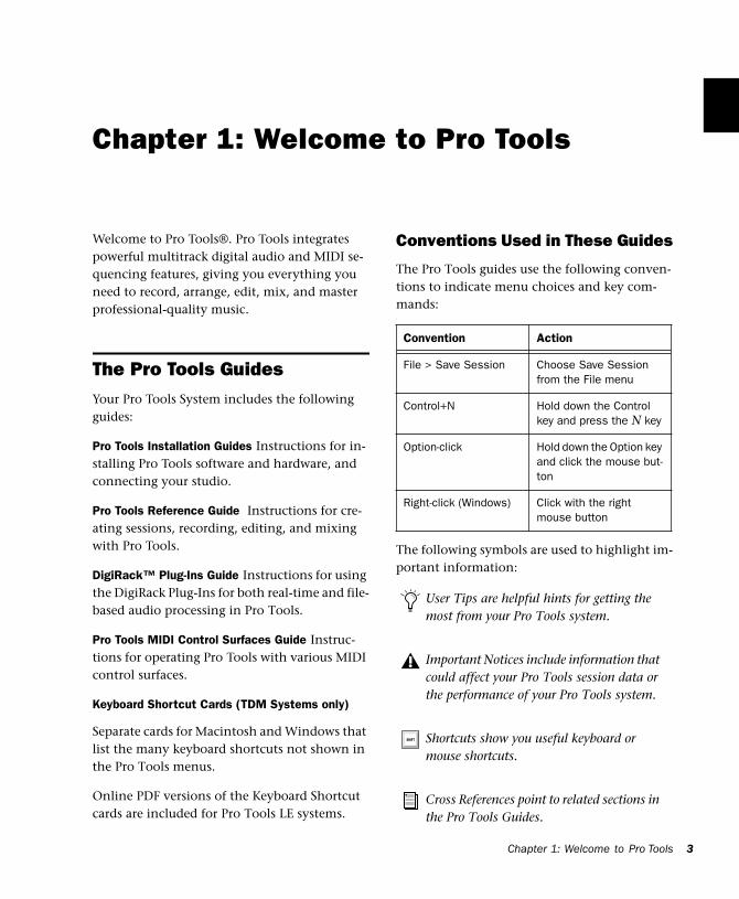
Conventions Used in These Guides
The Pro Tools guides use the following conven-tions to indicate menu choices and key com-mands::
The following symbols are used to highlight im-portant information:
Convention Action
File > Save Session Choose Save Session from the File menu
Control+N Hold down the Control key and press the N key
Option-click Hold down the Option key and click the mouse but-ton
Right-click (Windows) Click with the right mouse button
User Tips are helpful hints for getting the most from your Pro Tools system.
Important Notices include information that could affect your Pro Tools session data or the performance of your Pro Tools system.
Shortcuts show you useful keyboard or mouse shortcuts.
Cross References point to related sections in the Pro Tools Guides.
Chapter 1: Welcome to Pro Tools 3
4
Choose and Select
The words “choose” and “select” are often inter-changeable in conversational english. In this guide, however, there is a distinction between the two terms.
Select When the guide instructs you to select something, it stays selected. This is the case with dialog box options and menu items that enable or disable an option.
Choose When the guide instructs you to choose something, a one-time action is performed. This is the case with most menu commands; they perform their chosen action only once.
Compatibility InformationDigidesign can only assure compatibility and provide support for hardware and software it has tested and approved. For a list of Digidesign-qualified computers, operating systems, and third-party devices, refer to the latest compati-bility information on the Digidesign Web site:
www.digidesign.com/compato/
Digidesign RegistrationMake sure to complete and return the registra-tion card included with Pro Tools. Registered us-ers are entitled to one year of free technical sup-port, and will receive periodic software updates and upgrade notices.
Pro Tools Reference Guide
Chapter 2: Pro Tools System Configurations
TDM-equipped systemsPro Tools TDM-equipped systems are available in the following configurations:
Pro Tools 24 MIX
A core system includes:
• MIX Core card
• Pro Tools software
• Digidesign audio interface (sold separately)
Pro Tools 24 MIXplus
A core system includes:
• MIX Core card
• MIX Farm card
• Pro Tools software
• Digidesign audio interface (sold separately)
Pro Tools 24
A core system includes:
• d24 Audio card
• DSP Farm card
• Pro Tools software
• Digidesign audio interface (sold separately)
Supported Audio Interfaces
You can use the following audio interfaces with Pro Tools TDM systems:
◆ The 888/24 I/O and 882/20 I/O (as well as 888 I/O and 882 I/O) Audio Interfaces work with Pro Tools 24 MIX/MIXplus and Pro Tools 24 systems.
◆ The 1622 I/O Audio Interface works with Pro Tools 24 MIX/MIXplus and Pro Tools 24 systems.
◆ The ADAT Bridge I/O Interface works with Pro Tools 24 MIX/MIXplus and Pro Tools 24.
Pro Tools system performance depends on factors such as computer processor speed, amount of system memory, and hard drive performance. Contact your Digidesign dealer or visit Digidesign’s Web site for the latest system requirements and compatibil-ity information.
Chapter 2: Pro Tools System Configurations 5
6
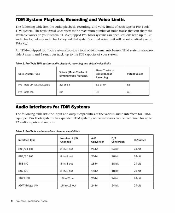
TDM System Playback, Recording and Voice LimitsThe following table lists the audio playback, recording, and voice limits of each type of Pro Tools TDM system. The term virtual voice refers to the maximum number of audio tracks that can share the available voices on your system. TDM-equipped Pro Tools systems can open sessions with up to 128 audio tracks, but any audio tracks beyond that system’s virtual voice limit will be automatically set to Voice Off.
All TDM-equipped Pro Tools systems provide a total of 64 internal mix busses. TDM systems also pro-vide 5 inserts and 5 sends per track, up to the DSP capacity of your system.
Table 1. Pro Tools TDM system audio playback, recording a
Pro Tools Reference Guide
nd virtual voice limits
Audio Interfaces for TDM SystemsThe following table lists the input and output capabilities of the various audio interfaces for TDM-equipped Pro Tools systems. In expanded TDM systems, audio interfaces can be combined for up to 72 audio inputs and outputs.
Core System TypeVoices (Mono Tracks of Simultaneous Playback)
Mono Tracks of Simultaneous Recording
Virtual Voices
Pro Tools 24 MIX/MIXplus 32 or 64 32 or 64 86
Pro Tools 24 32 32 43
Table 2. Pro Tools audio interface channel capabilities
Interface TypeNumber of I/OChannels
A/DConversion
D/AConversion
Digital I/O
888/24 I/O 8 in/8 out 24-bit 24-bit 24-bit
882/20 I/O 8 in/8 out 20-bit 20-bit 24-bit
888 I/O 8 in/8 out 18-bit 18-bit 24-bit
882 I/O 8 in/8 out 18-bit 18-bit 24-bit
1622 I/O 16 in/2 out 20-bit 24-bit 24-bit
ADAT Bridge I/O 16 in/16 out 24-bit 24-bit 24-bit
Pro Tools LE SystemsPro Tools LE-based systems are available in the following configurations.
Digi 001
A Digi 001 system includes:
• Digi 001 PCI card
• Digi 001 I/O box
• Pro Tools LE software
Digi ToolBox XP
An Digi ToolBox system includes:
• Audiomedia III card
• Pro Tools LE software
The total processing capacity of a Pro Tools LE-based system depends on the processing power of your computer. Contact your Digidesign dealer or visit Digidesign’s Web site for the latest system requirements and compatibility information.
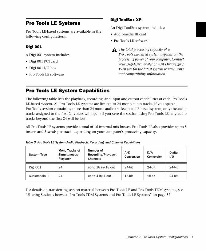
Pro Tools LE System CapabilitiesThe following table lists the playback, recording, and input and output capabilities of each Pro Tools LE-based system. All Pro Tools LE systems are limited to 24 mono audio tracks. If you open a Pro Tools session containing more than 24 mono audio tracks on an LE-based system, only the audio tracks assigned to the first 24 voices will open; if you save the session using Pro Tools LE, any audio tracks beyond the first 24 will be lost.
All Pro Tools LE systems provide a total of 16 internal mix busses. Pro Tools LE also provides up to 5 inserts and 5 sends per track, depending on your computer’s processing capacity.
Table 3. Pro Tools LE System Audio Playback, Recording, a
nd Channel CapabilitiesFor details on transferring session material between Pro Tools LE and Pro Tools TDM systems, see “Sharing Sessions between Pro Tools TDM Systems and Pro Tools LE Systems” on page 57.
System TypeMono Tracks of SimultaneousPlayback
Number of Recording/PlaybackChannels
A/DConversion
D/AConversion
Digital I/O
Digi 001 24 up to 18 in/18 out 24-bit 24-bit 24-bit
Audiomedia III 24 up to 4 in/4 out 18-bit 18-bit 24-bit
Chapter 2: Pro Tools System Configurations 7

8
Pro Tools Reference Guide
Chapter 3: Pro Tools Concepts
This chapter is an overview of essential digital audio, MIDI, and digital signal processing con-cepts, and an introduction to many of these same concepts in Pro Tools.
Hard Disk RecordingTape-based recording is a linear medium—you need to rewind or fast forward a tape to hear a particular spot in a recording. To rearrange or re-peat material in a linear system, you need to re-record it.
Hard disk recording is a non-linear (or random access) medium—you can go immediately to any spot in a recording without having to re-wind or fast forward.
Non-linear systems have several advantages. You can easily rearrange or repeat parts of a re-cording by making the hard disk read parts of the recording in a different order. In addition, this re-arrangement is non-destructive, meaning that the original recorded material is not al-tered.
Pro Tools is a non-linear recording system that let you rearrange and mix recorded material non-destructively.
The Digidesign Audio EngineWhen you start Pro Tools, an application called DAE automatically launches in the background. DAE, or the Digidesign Audio Engine, is Digide-sign’s real-time operating system for digital re-cording systems. When you install Pro Tools, DAE is automatically installed on your system.
In the same way that a computer’s operating system provides the foundation for programs that run on the computer, DAE provides much of the hard disk recording, digital signal process-ing, mix automation, and MIDI functionality re-quired by Pro Tools and other products from Digidesign and its Development Partners.
Pro Tools also takes advantage of your com-puter’s host processor, sharing certain tasks and processing. Performance is determined by your system and its Playback Engine settings.
See also “System Resources” on page 13.
Chapter 3: Pro Tools Concepts 9
10
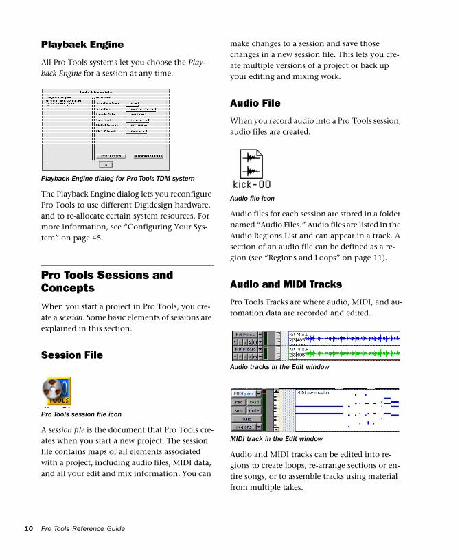
Playback Engine
All Pro Tools systems let you choose the Play-back Engine for a session at any time.
The Playback Engine dialog lets you reconfigure Pro Tools to use different Digidesign hardware, and to re-allocate certain system resources. For more information, see “Configuring Your Sys-tem” on page 45.
Pro Tools Sessions and ConceptsWhen you start a project in Pro Tools, you cre-ate a session. Some basic elements of sessions are explained in this section.
Session File
A session file is the document that Pro Tools cre-ates when you start a new project. The session file contains maps of all elements associated with a project, including audio files, MIDI data, and all your edit and mix information. You can
Playback Engine dialog for Pro Tools TDM system
Pro Tools session file icon
Pro Tools Reference Guide
make changes to a session and save those changes in a new session file. This lets you cre-ate multiple versions of a project or back up your editing and mixing work.
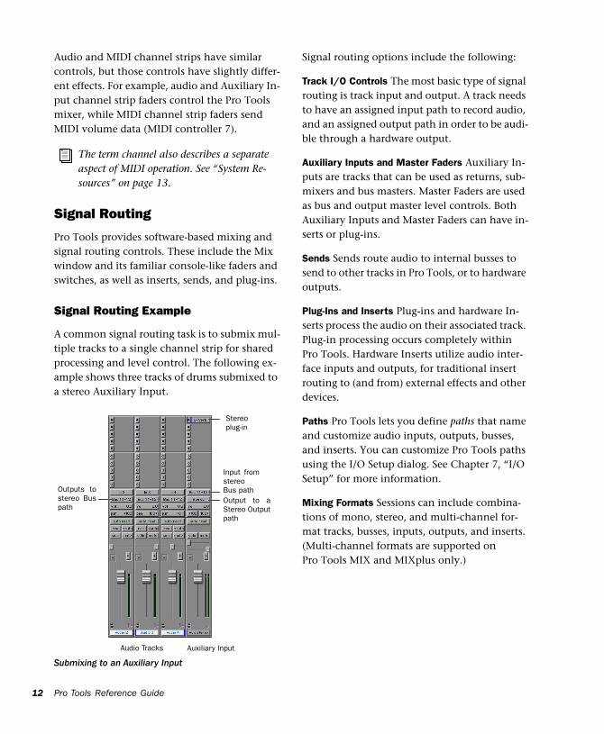
Audio File
When you record audio into a Pro Tools session, audio files are created.
Audio files for each session are stored in a folder named “Audio Files.” Audio files are listed in the Audio Regions List and can appear in a track. A section of an audio file can be defined as a re-gion (see “Regions and Loops” on page 11).
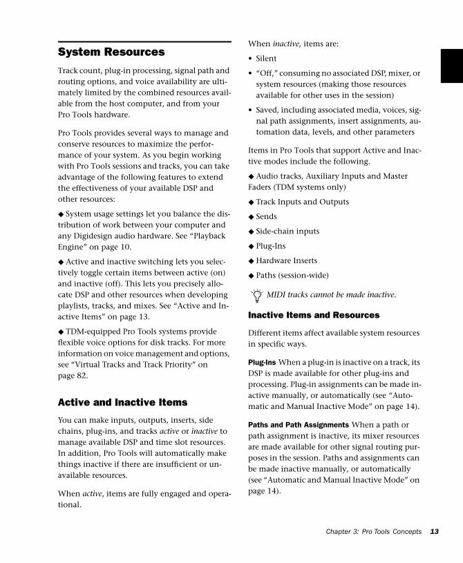
Audio and MIDI Tracks
Pro Tools Tracks are where audio, MIDI, and au-tomation data are recorded and edited.
Audio and MIDI tracks can be edited into re-gions to create loops, re-arrange sections or en-tire songs, or to assemble tracks using material from multiple takes.
Audio file icon
Audio tracks in the Edit window
MIDI track in the Edit window
Audio tracks can be mono, stereo, or any sup-ported multi-channel format (depending on your type of Pro Tools system).
Regions and Loops
A region is a piece of audio or MIDI data that may have associated automation data. A region could be a loop, a guitar riff, a verse of a song, a sound effect, a piece of dialog, or an entire sound file. In Pro Tools, regions are created from audio or MIDI files, and can be arranged in au-dio and MIDI track playlists.
Playlist
A playlist is a group of regions arranged on an audio or MIDI track. You can maintain multiple edit playlists on a single track. This lets you as-semble different versions on a single audio or MIDI track and choose among them with a pop-up menu on the track.
On audio tracks, a playlist tells the hard disk which audio files to read in what order. By using several copies of an audio region in a playlist, you can repeat a section of a recording without using any additional disk space.
Audio region
Playlist selector pop-up menu
A playlist can be made up of a single region or many separate regions. It can be made up of similar elements, such as regions from several different takes of a solo, or dissimilar elements, such as several sound effects.
Channel
The term channel is used to describe several re-lated components of a Pro Tools system. The first example of channel refers to a physical in-put or output of your Pro Tools system.
For example, an 888/24 I/O Audio Interface pro-vides eight channels of analog input and output to a TDM-equipped system. A Digi 001 system provides up to 18 channels of input and output to a Pro Tools LE system.
The second use of the term channel refers to a mixer strip in the Pro Tools Mix window. The term channel strip refers to the mixer strip of any track (audio or MIDI track, Auxiliary Input, or Master Fader) in a session.
Rear view of 888/24 I/O Interface
Channel strip in the Mix window
Computer 1
ANALOG OUTPUT ANALOG INPUT AES/EBU OUTPUT AES/EBU INPUT
Computer 2
8 CH Mode2 x 4 CH Mode
S/PDIFIN
S/PDIFOUT
SLAVE CLOCKIN
SLAVE CLOCKOUT
7
8
5
6
3
4
1
2
7
8
5
6
3
4
1
2
5/6
7/8
1/2
3/4
5/6
7/8
1/2
3/4
Chapter 3: Pro Tools Concepts 11
12
Audio and MIDI channel strips have similar controls, but those controls have slightly differ-ent effects. For example, audio and Auxiliary In-put channel strip faders control the Pro Tools mixer, while MIDI channel strip faders send MIDI volume data (MIDI controller 7).
Signal Routing
Pro Tools provides software-based mixing and signal routing controls. These include the Mix window and its familiar console-like faders and switches, as well as inserts, sends, and plug-ins.
Signal Routing Example
A common signal routing task is to submix mul-tiple tracks to a single channel strip for shared processing and level control. The following ex-ample shows three tracks of drums submixed to a stereo Auxiliary Input.
The term channel also describes a separate aspect of MIDI operation. See “System Re-sources” on page 13.
Submixing to an Auxiliary Input
Audio Tracks Auxiliary Input
Input fromstereoBus path
Stereoplug-in
Output to aStereo Outputpath
Outputs tostereo Buspath
Pro Tools Reference Guide
Signal routing options include the following:
Track I/O Controls The most basic type of signal routing is track input and output. A track needs to have an assigned input path to record audio, and an assigned output path in order to be audi-ble through a hardware output.
Auxiliary Inputs and Master Faders Auxiliary In-puts are tracks that can be used as returns, sub-mixers and bus masters. Master Faders are used as bus and output master level controls. Both Auxiliary Inputs and Master Faders can have in-serts or plug-ins.
Sends Sends route audio to internal busses to send to other tracks in Pro Tools, or to hardware outputs.
Plug-Ins and Inserts Plug-ins and hardware In-serts process the audio on their associated track. Plug-in processing occurs completely within Pro Tools. Hardware Inserts utilize audio inter-face inputs and outputs, for traditional insert routing to (and from) external effects and other devices.
Paths Pro Tools lets you define paths that name and customize audio inputs, outputs, busses, and inserts. You can customize Pro Tools paths using the I/O Setup dialog. See Chapter 7, “I/O Setup” for more information.
Mixing Formats Sessions can include combina-tions of mono, stereo, and multi-channel for-mat tracks, busses, inputs, outputs, and inserts. (Multi-channel formats are supported on Pro Tools MIX and MIXplus only.)
System ResourcesTrack count, plug-in processing, signal path and routing options, and voice availability are ulti-mately limited by the combined resources avail-able from the host computer, and from your Pro Tools hardware.
Pro Tools provides several ways to manage and conserve resources to maximize the perfor-mance of your system. As you begin working with Pro Tools sessions and tracks, you can take advantage of the following features to extend the effectiveness of your available DSP and other resources:
◆ System usage settings let you balance the dis-tribution of work between your computer and any Digidesign audio hardware. See “Playback Engine” on page 10.
◆ Active and inactive switching lets you selec-tively toggle certain items between active (on) and inactive (off). This lets you precisely allo-cate DSP and other resources when developing playlists, tracks, and mixes. See “Active and In-active Items” on page 13.
◆ TDM-equipped Pro Tools systems provide flexible voice options for disk tracks. For more information on voice management and options, see “Virtual Tracks and Track Priority” on page 82.
Active and Inactive Items
You can make inputs, outputs, inserts, side chains, plug-ins, and tracks active or inactive to manage available DSP and time slot resources. In addition, Pro Tools will automatically make things inactive if there are insufficient or un-available resources.
When active, items are fully engaged and opera-tional.
When inactive, items are:
• Silent
• “Off,” consuming no associated DSP, mixer, or system resources (making those resources available for other uses in the session)
• Saved, including associated media, voices, sig-nal path assignments, insert assignments, au-tomation data, levels, and other parameters
Items in Pro Tools that support Active and Inac-tive modes include the following.
◆ Audio tracks, Auxiliary Inputs and Master Faders (TDM systems only)
◆ Track Inputs and Outputs
◆ Sends
◆ Side-chain inputs
◆ Plug-Ins
◆ Hardware Inserts
◆ Paths (session-wide)
Inactive Items and Resources
Different items affect available system resources in specific ways.
Plug-Ins When a plug-in is inactive on a track, its DSP is made available for other plug-ins and processing. Plug-in assignments can be made in-active manually, or automatically (see “Auto-matic and Manual Inactive Mode” on page 14).
Paths and Path Assignments When a path or path assignment is inactive, its mixer resources are made available for other signal routing pur-poses in the session. Paths and assignments can be made inactive manually, or automatically (see “Automatic and Manual Inactive Mode” on page 14).
MIDI tracks cannot be made inactive.
Chapter 3: Pro Tools Concepts 13
14
Tracks (TDM systems only) When an audio track, Auxiliary Input, or Master Fader is made inactive, its plug-ins, inserts, sends, and I/O assignments become inactive.
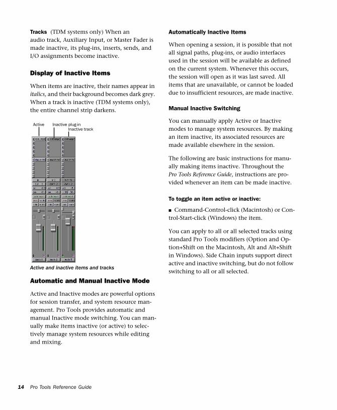
Display of Inactive Items
When items are inactive, their names appear in italics, and their background becomes dark grey. When a track is inactive (TDM systems only), the entire channel strip darkens.
Automatic and Manual Inactive Mode
Active and Inactive modes are powerful options for session transfer, and system resource man-agement. Pro Tools provides automatic and manual Inactive mode switching. You can man-ually make items inactive (or active) to selec-tively manage system resources while editing and mixing.
Active and inactive items and tracks
Active Inactive plug-in Inactive track
Pro Tools Reference Guide
Automatically Inactive Items
When opening a session, it is possible that not all signal paths, plug-ins, or audio interfaces used in the session will be available as defined on the current system. Whenever this occurs, the session will open as it was last saved. All items that are unavailable, or cannot be loaded due to insufficient resources, are made inactive.
Manual Inactive Switching
You can manually apply Active or Inactive modes to manage system resources. By making an item inactive, its associated resources are made available elsewhere in the session.
The following are basic instructions for manu-ally making items inactive. Throughout the Pro Tools Reference Guide, instructions are pro-vided whenever an item can be made inactive.
To toggle an item active or inactive:
■ Command-Control-click (Macintosh) or Con-trol-Start-click (Windows) the item.
You can apply to all or all selected tracks using standard Pro Tools modifiers (Option and Op-tion+Shift on the Macintosh, Alt and Alt+Shift in Windows). Side Chain inputs support direct active and inactive switching, but do not follow switching to all or all selected.
MIDI ConceptsMIDI (Musical Instrument Digital Interface) is a communication protocol for musical instru-ments. This industry standard enables connec-tions between a variety of devices from different manufacturers. Examples of MIDI-compatible equipment include synthesizers, sound mod-ules, drum machines, patch bays, effects proces-sors, MIDI interfaces, and sequencers.
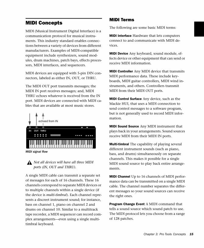
MIDI devices are equipped with 5-pin DIN con-nectors, labeled as either IN, OUT, or THRU.
The MIDI OUT port transmits messages; the MIDI IN port receives messages; and, MIDI THRU echoes whatever is received from the IN port. MIDI devices are connected with MIDI ca-bles that are available at most music stores.
A single MIDI cable can transmit a separate set of messages for each of 16 channels. These 16 channels correspond to separate MIDI devices or to multiple channels within a single device (if the device is multi-timbral). Each channel repre-sents a discreet instrument sound; for instance, bass on channel 1, piano on channel 2 and drums on channel 10. Similar to a multitrack tape recorder, a MIDI sequencer can record com-plex arrangements—even using a single multi-timbral keyboard.
MIDI signal flow
Not all devices will have all three MIDI ports (IN, OUT and THRU).
echoed from IN
MIDI Terms
The following are some basic MIDI terms:
MIDI Interface Hardware that lets computers connect to and communicate with MIDI de-vices.
MIDI Device Any keyboard, sound module, ef-fects device or other equipment that can send or receive MIDI information.
MIDI Controller Any MIDI device that transmits MIDI performance data. These include key-boards, MIDI guitar controllers, MIDI wind in-struments, and others. Controllers transmit MIDI from their MIDI OUT ports.
MIDI Control Surface Any device, such as the Mackie HUI, that uses a MIDI connection to send control messages to a software program, but is not generally used to record MIDI infor-mation.
MIDI Sound Source Any MIDI instrument that plays back in your arrangements. Sound sources receive MIDI from their MIDI IN ports.
Multi-timbral The capability of playing several different instrument sounds (such as piano, bass, and drums) simultaneously on separate channels. This makes it possible for a single MIDI sound source to play back entire arrange-ments.
MIDI Channel Up to 16 channels of MIDI perfor-mance data can be transmitted on a single MIDI cable. The channel number separates the differ-ent messages so your sound sources can receive the right ones.
Program Change Event A MIDI command that tells a sound source which sound patch to use. The MIDI protocol lets you choose from a range of 128 patches.
Chapter 3: Pro Tools Concepts 15
16
Bank Select Message A MIDI command that specifies the bank of patches from which to choose. Many devices have more than 128 patches and Bank Select messages provide a means of accessing them.
Local Control A controller setting found on most MIDI keyboards that let them play their own sound source. Disabling “local control” ensures that a device’s internal sound source is only played by external MIDI messages.
When using Pro Tools, “local control” should usually be disabled. When “local control” is off, your keyboard still transmits data to its MIDI OUT port.
Continuous Controller Events MIDI instructions that allow real-time changes to notes that are currently sounding. These include pitch bend, modulation, volume, pan, and many others.
System Exclusive Data MIDI data commonly used for sending and retrieving patch parameter information for storage purposes.
Common Misconceptions about MIDI
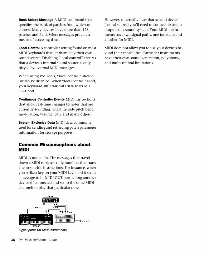
MIDI is not audio. The messages that travel down a MIDI cable are only numbers that trans-late to specific instructions. For instance, when you strike a key on your MIDI keyboard it sends a message to its MIDI OUT port telling another device (if connected and set to the same MIDI channel) to play that particular note.
Signal paths for MIDI instruments
Pro Tools Reference Guide
However, to actually hear that second device (sound source) you’ll need to connect its audio outputs to a sound system. Your MIDI instru-ments have two signal paths, one for audio and another for MIDI.
MIDI does not allow you to use your devices be-yond their capabilities. Particular instruments have their own sound generation, polyphony, and multi-timbral limitations.
Chapter 4: Pro Tools Windows
Pro Tools provides two complementary ways of viewing a project: the Mix window and the Edit window. Pro Tools also allows you to control many functions from the Transport window. The main elements of these windows are ex-plained in the following sections.
The Mix Window In the Mix window, tracks appear as mixer mod-ules, with controls for inserts, sends, input and output assignments, volume, panning, record-enable, automation mode, and solo/mute. The following section explains each of these track controls.
To display the Pro Tools input/output controls, inserts, sends, and comments, select Display > Mix Window Shows > All.
To toggle between the Mix and Edit win-dows, press Command+equal (Macintosh) or Control+equal (Windows) on the alpha keyboard.
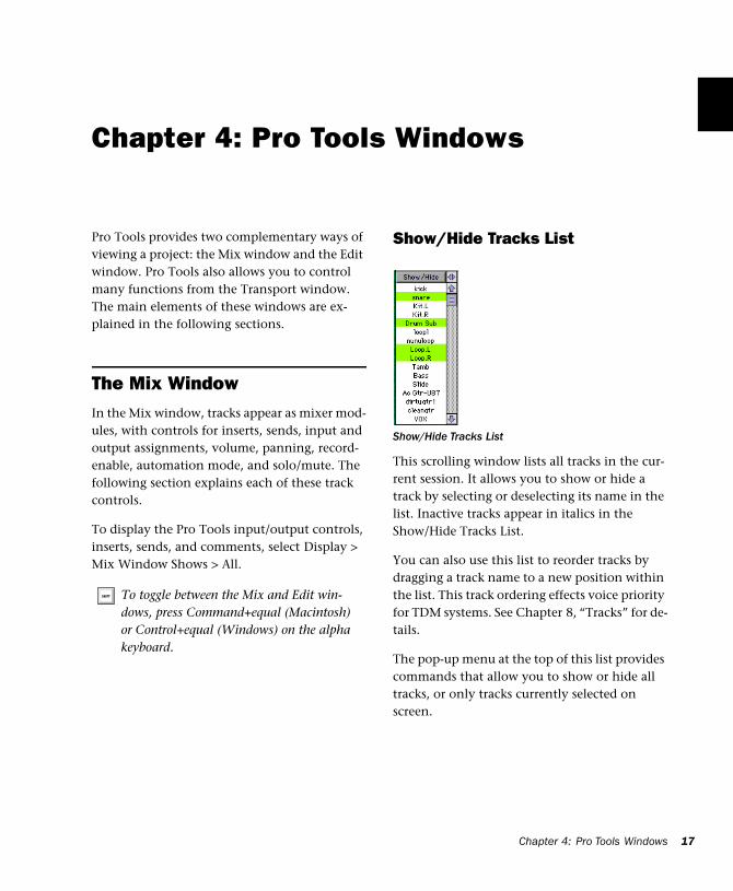
Show/Hide Tracks List
This scrolling window lists all tracks in the cur-rent session. It allows you to show or hide a track by selecting or deselecting its name in the list. Inactive tracks appear in italics in the Show/Hide Tracks List.
You can also use this list to reorder tracks by dragging a track name to a new position within the list. This track ordering effects voice priority for TDM systems. See Chapter 8, “Tracks” for de-tails.
The pop-up menu at the top of this list provides commands that allow you to show or hide all tracks, or only tracks currently selected on screen.
Show/Hide Tracks List
Chapter 4: Pro Tools Windows 17
18
About Groups and Show/Hide Tracks
Even if a track is hidden, if it is a member of an enabled group, all Mix window operations per-formed on other members of the group will also affect the hidden track—with the exception of au-dio or MIDI record-enabling. If you solo, mute, or automation write-enable a grouped track, any group members that are hidden will be soloed, muted, or automation write-enabled as well. These functions are not applied to hidden tracks.
In the Edit window, however, editing operations performed on members of an enabled group will not affect hidden tracks that are also members of the enabled group.
On TDM systems, even if a track is hidden from view, its position relative to other tracks still af-fects its virtual track playback priority (see “Vir-tual Tracks and Track Priority” on page 82 for details).
Mix Groups List
The Mix Groups list shows all groups in the ses-sion. It allows you to activate a group by select-ing its name in the list. A group is only enabled (meaning that its members are linked for mix-ing purposes), when its name is highlighted in this list.
Mix Groups List
Pro Tools Reference Guide
You can also use this list to select grouped tracks on-screen by clicking to the left of the dotted vertical line next to a group name. The pop-up menu at the top of this list provides commands to create, delete or suspend groups. You can link groups in the Mix Groups and Edit Groups lists. For more information on grouping, see “Group-ing Tracks” on page 85.
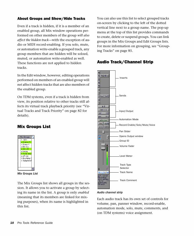
Audio Track/Channel Strip
Each audio track has its own set of controls for volume, pan, panner window, record-enable, automation mode, solo, mute, comments, and (on TDM systems) voice assignment.
Audio channel strip
Inserts
Sends
Input/Output
Record Enable/Solo/Mute/Voice
Automation Mode
Track Name
Pan Slider
Level Meter
Volume Fader
Group ID
Opens Output window
Track Comment
Track Type Selector
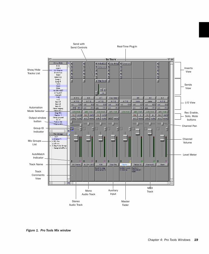
Figure 1. Pro Tools Mix window
Inserts View
Sends View
Show/HideTracks List
Mix Groups List
ChannelVolume
Channel Pa
Level Met
Group IDIndicator
StereoAudio Track
AuxiliaryInput
Track Name
TrackComments
View
MasterFader
AutoMatch Indicator
I/O View
Real-Time Plug-InSend with
Send Controls
Rec EnaSolo, Mu
button
Automation Mode Selector
Output window button
MIDITrackMono
Audio Track
Chapter 4: Pro Tools W
n
er
i
ble, te
s
ndows 19
20
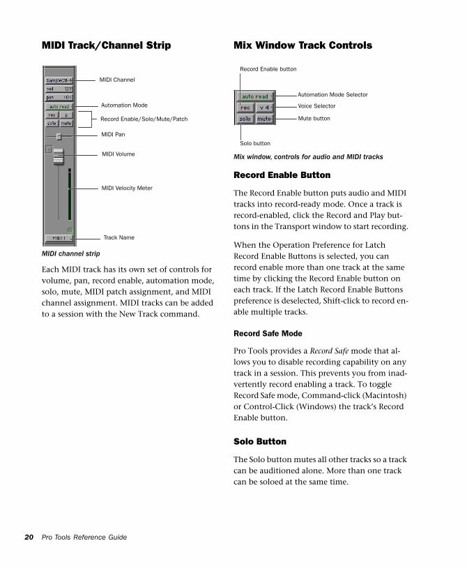
MIDI Track/Channel Strip
Each MIDI track has its own set of controls for volume, pan, record enable, automation mode, solo, mute, MIDI patch assignment, and MIDI channel assignment. MIDI tracks can be added to a session with the New Track command.
MIDI channel strip
MIDI Channel
MIDI Volume
MIDI Pan
Record Enable/Solo/Mute/Patch
Track Name
MIDI Velocity Meter
Automation Mode
Pro Tools Reference Guide
Mix Window Track Controls
Record Enable Button
The Record Enable button puts audio and MIDI tracks into record-ready mode. Once a track is record-enabled, click the Record and Play but-tons in the Transport window to start recording.
When the Operation Preference for Latch Record Enable Buttons is selected, you can record enable more than one track at the same time by clicking the Record Enable button on each track. If the Latch Record Enable Buttons preference is deselected, Shift-click to record en-able multiple tracks.
Record Safe Mode
Pro Tools provides a Record Safe mode that al-lows you to disable recording capability on any track in a session. This prevents you from inad-vertently record enabling a track. To toggle Record Safe mode, Command-click (Macintosh) or Control-Click (Windows) the track’s Record Enable button.
Solo Button
The Solo button mutes all other tracks so a track can be auditioned alone. More than one track can be soloed at the same time.
Mix window, controls for audio and MIDI tracks
Automation Mode Selector
Solo button
Mute button
Record Enable button
Voice Selector
When the Operation Preference for Latch Solo Buttons is selected, you can solo more than one track at the same time by clicking the Solo but-ton for each track. If the Latch Solo Buttons preference is deselected, you can Shift-click to solo multiple tracks.
Solo Safe Mode
Pro Tools also allows you to solo safe a track. This prevents the track from being muted even if you solo other tracks. This feature is useful for tracks such as Auxiliary Inputs that are being used as effects returns (for example, a reverb send), allowing the effects track to remain in a mix even when other tracks are soloed. It is also useful to solo safe MIDI tracks so that their play-back is not affected when you solo audio tracks. To toggle Solo Safe mode, Command-click (Macintosh) or Control-Click (Windows) the Solo button on the track. Do this again to turn off Solo Safe on a track.
Mute Button
The Mute button silences a track. More than one track can be muted at the same time. On TDM systems, if the Mute Frees Assigned Voice option is selected, muting a track will free up any voices
allocate its voice to the next highest priority vir-tual track allocated to that voice in your session.
Automation Mode Selector
The Automation Mode selector allows you to choose a track’s automation mode. Once a track is automation write-enabled, starting playback will start writing automation (depending on the mode you have chosen). Any automation moves that you make on the track can then be played back exactly as you performed them.
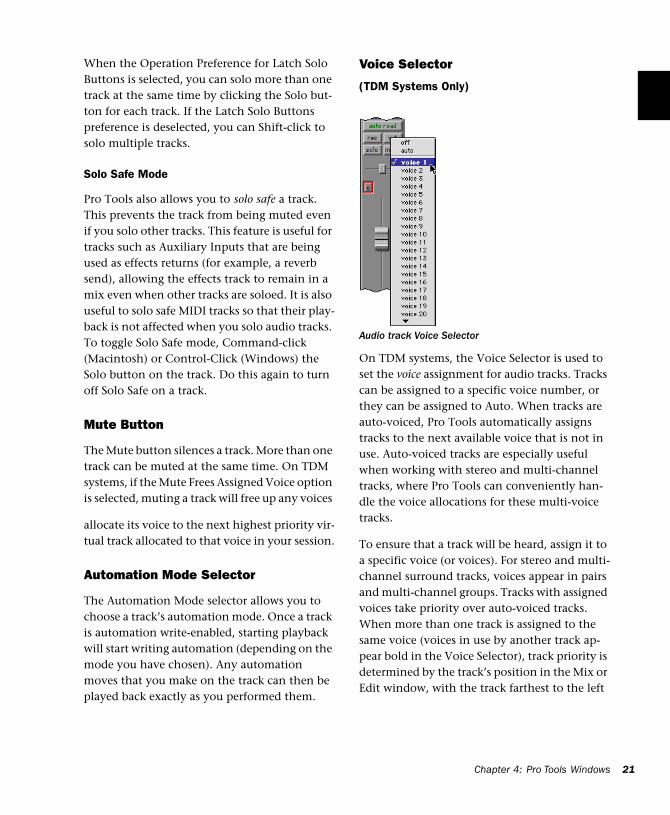
Voice Selector
(TDM Systems Only)
On TDM systems, the Voice Selector is used to set the voice assignment for audio tracks. Tracks can be assigned to a specific voice number, or they can be assigned to Auto. When tracks are auto-voiced, Pro Tools automatically assigns tracks to the next available voice that is not in use. Auto-voiced tracks are especially useful when working with stereo and multi-channel tracks, where Pro Tools can conveniently han-dle the voice allocations for these multi-voice tracks.
To ensure that a track will be heard, assign it to a specific voice (or voices). For stereo and multi-channel surround tracks, voices appear in pairs and multi-channel groups. Tracks with assigned voices take priority over auto-voiced tracks. When more than one track is assigned to the same voice (voices in use by another track ap-pear bold in the Voice Selector), track priority is determined by the track’s position in the Mix or Edit window, with the track farthest to the left
Audio track Voice Selector
Chapter 4: Pro Tools Windows 21
22
in the Mix window, or closest to the top in the Edit window, being given priority. This track priority scheme also applies to tracks that are auto-voiced.
For more information on voices and track prior-ity, see “Assigning Voices and Track Priority” on page 80.
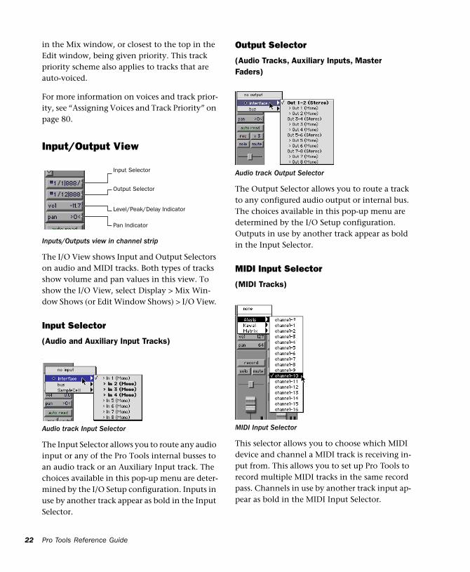
Input/Output View
The I/O View shows Input and Output Selectors on audio and MIDI tracks. Both types of tracks show volume and pan values in this view. To show the I/O View, select Display > Mix Win-dow Shows (or Edit Window Shows) > I/O View.
Input Selector
(Audio and Auxiliary Input Tracks)
The Input Selector allows you to route any audio input or any of the Pro Tools internal busses to an audio track or an Auxiliary Input track. The choices available in this pop-up menu are deter-mined by the I/O Setup configuration. Inputs in use by another track appear as bold in the Input Selector.
Inputs/Outputs view in channel strip
‘
Audio track Input Selector
Input Selector
Level/Peak/Delay Indicator
Pan Indicator
Output Selector
Pro Tools Reference Guide
Output Selector
(Audio Tracks, Auxiliary Inputs, Master Faders)
The Output Selector allows you to route a track to any configured audio output or internal bus. The choices available in this pop-up menu are determined by the I/O Setup configuration. Outputs in use by another track appear as bold in the Input Selector.
MIDI Input Selector
(MIDI Tracks)
This selector allows you to choose which MIDI device and channel a MIDI track is receiving in-put from. This allows you to set up Pro Tools to record multiple MIDI tracks in the same record pass. Channels in use by another track input ap-pear as bold in the MIDI Input Selector.
Audio track Output Selector
MIDI Input Selector
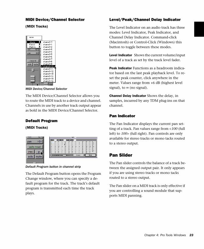
MIDI Device/Channel Selector
(MIDI Tracks)
The MIDI Device/Channel Selector allows you to route the MIDI track to a device and channel. Channels in use by another track output appear as bold in the MIDI Device/Channel Selector.
Default Program
(MIDI Tracks)
The Default Program button opens the Program Change window, where you can specify a de-fault program for the track. The track’s default program is transmitted each time the track plays.
MIDI Device/Channel Selector
Default Program button in channel strip
Level/Peak/Channel Delay Indicator
The Level Indicator on an audio track has three modes: Level Indicator, Peak Indicator, and Channel Delay Indicator. Command-click (Macintosh) or Control-Click (Windows) this button to toggle between these modes.
Level Indicator Shows the current volume/input level of a track as set by the track level fader.
Peak Indicator Functions as a headroom indica-tor based on the last peak playback level. To re-set the peak counter, click anywhere in the meter. Values range from +6 dB (highest level signal), to ∞ (no signal).
Channel Delay Indicator Shows the delay, in samples, incurred by any TDM plug-ins on that channel.
Pan Indicator
The Pan Indicator displays the current pan set-ting of a track. Pan values range from <100 (full left) to 100> (full right). Pan controls are only available for stereo tracks or mono tacks routed to a stereo output.
Pan Slider
The Pan slider controls the balance of a track be-tween the assigned output pair. It only appears if you are using stereo tracks or mono tacks routed to a stereo output.
The Pan slider on a MIDI track is only effective if you are controlling a sound module that sup-ports MIDI panning.
Chapter 4: Pro Tools Windows 23
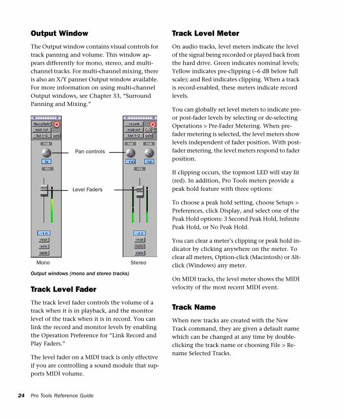
24
Output Window
The Output window contains visual controls for track panning and volume. This window ap-pears differently for mono, stereo, and multi-channel tracks. For multi-channel mixing, there is also an X/Y panner Output window available. For more information on using multi-channel Output windows, see Chapter 33, “Surround Panning and Mixing.”
Track Level Fader
The track level fader controls the volume of a track when it is in playback, and the monitor level of the track when it is in record. You can link the record and monitor levels by enabling the Operation Preference for “Link Record and Play Faders.”
The level fader on a MIDI track is only effective if you are controlling a sound module that sup-ports MIDI volume.
Output windows (mono and stereo tracks)
Pan controls
Level Faders
Mono Stereo
Pro Tools Reference Guide
Track Level Meter
On audio tracks, level meters indicate the level of the signal being recorded or played back from the hard drive. Green indicates nominal levels; Yellow indicates pre-clipping (–6 dB below full scale); and Red indicates clipping. When a track is record-enabled, these meters indicate record levels.
You can globally set level meters to indicate pre-or post-fader levels by selecting or de-selecting Operations > Pre-Fader Metering. When pre-fader metering is selected, the level meters show levels independent of fader position. With post-fader metering, the level meters respond to fader position.
If clipping occurs, the topmost LED will stay lit (red). In addition, Pro Tools meters provide a peak hold feature with three options:
To choose a peak hold setting, choose Setups > Preferences, click Display, and select one of the Peak Hold options: 3 Second Peak Hold, Infinite Peak Hold, or No Peak Hold.
You can clear a meter’s clipping or peak hold in-dicator by clicking anywhere on the meter. To clear all meters, Option-click (Macintosh) or Alt-click (Windows) any meter.
On MIDI tracks, the level meter shows the MIDI velocity of the most recent MIDI event.
Track Name
When new tracks are created with the New Track command, they are given a default name which can be changed at any time by double-clicking the track name or choosing File > Re-name Selected Tracks.
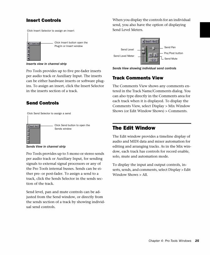
Insert Controls
Pro Tools provides up to five pre-fader inserts per audio track or Auxiliary Input. The inserts can be either hardware inserts or software plug-ins. To assign an insert, click the Insert Selector in the inserts section of a track.
Send Controls
Pro Tools provides up to 5 mono or stereo sends per audio track or Auxiliary Input, for sending signals to external signal processors or any of the Pro Tools internal busses. Sends can be ei-ther pre- or post-fader. To assign a send to a track, click the Sends Selector in the sends sec-tion of the track.
Send level, pan and mute controls can be ad-justed from the Send window, or directly from the sends section of a track by showing individ-ual send controls.
Inserts view in channel strip
Sends View in channel strip
Click Insert Selector to assign an insert
Click Insert button open the Plug-In or Insert window
Click Send Selector to assign a send
Click Send button to open the Sends window
When you display the controls for an individual send, you also have the option of displaying Send Level Meters.
Track Comments View
The Comments View shows any comments en-tered in the Track Name/Comments dialog. You can also type directly in the Comments area for each track when it is displayed. To display the Comments View, select Display > Mix Window Shows (or Edit Window Shows) > Comments.
The Edit WindowThe Edit window provides a timeline display of audio and MIDI data and mixer automation for editing and arranging tracks. As in the Mix win-dow, each track has controls for record enable, solo, mute and automation mode.
To display the input and output controls, in-serts, sends, and comments, select Display > Edit Window Shows > All.
Sends View showing individual send controls
Send PanSend Level
Send Level MeterPre/Post button
Send Mute
Chapter
4 : Pro Tools Windows 25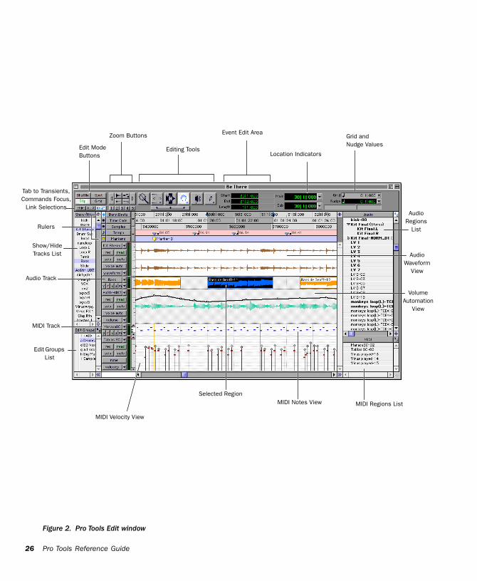
26
Figure 2. Pro Tools Edit window
Rulers
AudioWaveform
View
AudioRegions
List
MIDI Regions List
how/Hide racks List
Edit Mode Buttons
Event Edit Area
Editing Tools
Zoom Buttons
Location Indicators
Grid and Nudge Values
MIDI Notes View
VolumeAutomati
View
MIDI Velocity View
Selected Region
io Track
IDI Track
o Transients,ands Focus,
Selections
dit Groups List
Pro Tools Reference Guide
ST
on
Aud
M
Tab tComm
Link
E
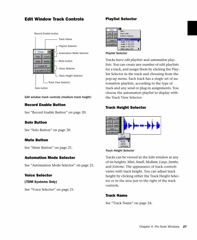
Edit Window Track Controls
Record Enable Button
See “Record Enable Button” on page 20.
Solo Button
See “Solo Button” on page 20.
Mute Button
See “Mute Button” on page 21.
Automation Mode Selector
See “Automation Mode Selector” on page 21.
Voice Selector
(TDM Systems Only)
See “Voice Selector” on page 21.
Edit window track controls (medium track height)
Automation Mode Selector
Mute button
Voice Selector
Track Height Selector
Playlist Selector
Track Name
Track View Selector
Record Enable button
Solo button
Playlist Selector
Tracks have edit playlists and automation play-lists. You can create any number of edit playlists for a track, and assign them by clicking the Play-list Selector in the track and choosing from the pop-up menu. Each track has a single set of au-tomation playlists, according to the type of track and any send or plug-in assignments. You choose the automation playlist to display with the Track View Selector.
Track Height Selector
Tracks can be viewed in the Edit window at any of six heights: Mini, Small, Medium, Large, Jumbo, and Extreme. The appearance of track controls varies with track height. You can adjust track height by clicking either the Track Height Selec-tor or in the area just to the right of the track controls.
Track Name
See “Track Name” on page 24.
Playlist Selector
Track Height Selector
Chapter 4: Pro Tools Windows 27
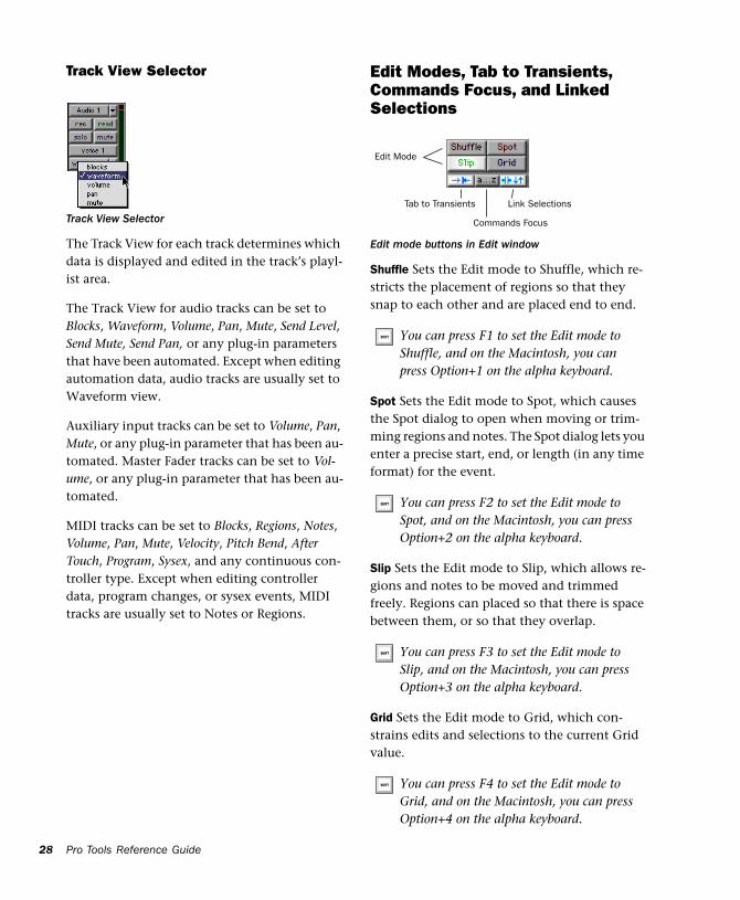
28
Track View Selector
The Track View for each track determines which data is displayed and edited in the track’s playl-ist area.
The Track View for audio tracks can be set to Blocks, Waveform, Volume, Pan, Mute, Send Level, Send Mute, Send Pan, or any plug-in parameters that have been automated. Except when editing automation data, audio tracks are usually set to Waveform view.
Auxiliary input tracks can be set to Volume, Pan, Mute, or any plug-in parameter that has been au-tomated. Master Fader tracks can be set to Vol-ume, or any plug-in parameter that has been au-tomated.
MIDI tracks can be set to Blocks, Regions, Notes, Volume, Pan, Mute, Velocity, Pitch Bend, After Touch, Program, Sysex, and any continuous con-troller type. Except when editing controller data, program changes, or sysex events, MIDI tracks are usually set to Notes or Regions.
Track View Selector
Pro Tools Reference Guide
Edit Modes, Tab to Transients, Commands Focus, and Linked Selections
Shuffle Sets the Edit mode to Shuffle, which re-stricts the placement of regions so that they snap to each other and are placed end to end.
Spot Sets the Edit mode to Spot, which causes the Spot dialog to open when moving or trim-ming regions and notes. The Spot dialog lets you enter a precise start, end, or length (in any time format) for the event.
Slip Sets the Edit mode to Slip, which allows re-gions and notes to be moved and trimmed freely. Regions can placed so that there is space between them, or so that they overlap.
Grid Sets the Edit mode to Grid, which con-strains edits and selections to the current Grid value.
Edit mode buttons in Edit window
You can press F1 to set the Edit mode to Shuffle, and on the Macintosh, you can press Option+1 on the alpha keyboard.
You can press F2 to set the Edit mode to Spot, and on the Macintosh, you can press Option+2 on the alpha keyboard.
You can press F3 to set the Edit mode to Slip, and on the Macintosh, you can press Option+3 on the alpha keyboard.
You can press F4 to set the Edit mode to Grid, and on the Macintosh, you can press Option+4 on the alpha keyboard.
Commands Focus
Edit Mode
Link SelectionsTab to Transients
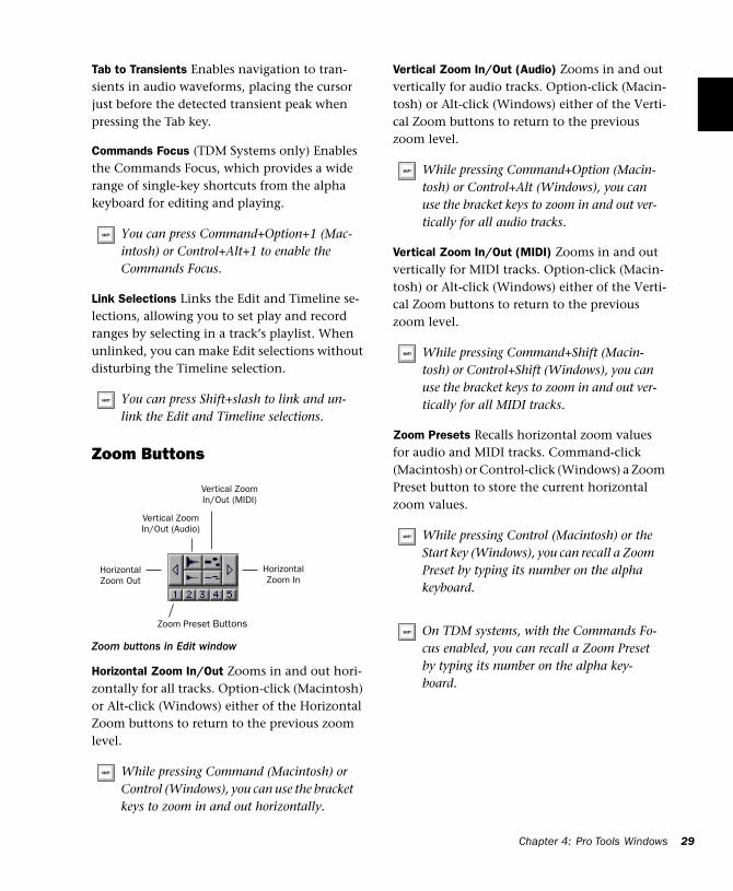
Tab to Transients Enables navigation to tran-sients in audio waveforms, placing the cursor just before the detected transient peak when pressing the Tab key.
Commands Focus (TDM Systems only) Enables the Commands Focus, which provides a wide range of single-key shortcuts from the alpha keyboard for editing and playing.
Link Selections Links the Edit and Timeline se-lections, allowing you to set play and record ranges by selecting in a track’s playlist. When unlinked, you can make Edit selections without disturbing the Timeline selection.
Zoom Buttons
Horizontal Zoom In/Out Zooms in and out hori-zontally for all tracks. Option-click (Macintosh) or Alt-click (Windows) either of the Horizontal Zoom buttons to return to the previous zoom level.
You can press Command+Option+1 (Mac-intosh) or Control+Alt+1 to enable the Commands Focus.
You can press Shift+slash to link and un-link the Edit and Timeline selections.
Zoom buttons in Edit window
While pressing Command (Macintosh) or Control (Windows), you can use the bracket keys to zoom in and out horizontally.
Zoom Preset Buttons
HorizontalZoom In
HorizontalZoom Out
Vertical Zoom In/Out (Audio)
Vertical Zoom In/Out (MIDI)
Vertical Zoom In/Out (Audio) Zooms in and out vertically for audio tracks. Option-click (Macin-tosh) or Alt-click (Windows) either of the Verti-cal Zoom buttons to return to the previous zoom level.
Vertical Zoom In/Out (MIDI) Zooms in and out vertically for MIDI tracks. Option-click (Macin-tosh) or Alt-click (Windows) either of the Verti-cal Zoom buttons to return to the previous zoom level.
Zoom Presets Recalls horizontal zoom values for audio and MIDI tracks. Command-click (Macintosh) or Control-click (Windows) a Zoom Preset button to store the current horizontal zoom values.
While pressing Command+Option (Macin-tosh) or Control+Alt (Windows), you can use the bracket keys to zoom in and out ver-tically for all audio tracks.
While pressing Command+Shift (Macin-tosh) or Control+Shift (Windows), you can use the bracket keys to zoom in and out ver-tically for all MIDI tracks.
While pressing Control (Macintosh) or the Start key (Windows), you can recall a Zoom Preset by typing its number on the alpha keyboard.
On TDM systems, with the Commands Fo-cus enabled, you can recall a Zoom Preset by typing its number on the alpha key-board.
Chapter 4: Pro Tools Windows 29
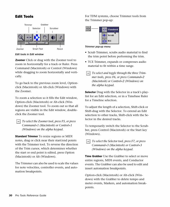
30
Edit Tools
Zoomer Click or drag with the Zoomer tool to zoom in horizontally for a track or Ruler. Press Command (Macintosh) or Control (Windows) while dragging to zoom horizontally and verti-cally.
To go back to the previous zoom level, Option-click (Macintosh) or Alt-click (Windows) with the Zoomer.
To zoom a selection so it fills the Edit window, Option-click (Macintosh) or Alt-click (Win-dows) the Zoomer tool. To zoom out so that all regions are visible in the Edit window, double-click the Zoomer tool.
Standard Trimmer To resize regions or MIDI notes, drag or click near their start/end points with the Trimmer tool. To reverse the direction of the Trim cursor, which determines whether the start or end point is edited, press Option (Macintosh) or Alt (Windows).
The Trimmer can also be used to scale the values for note velocities, controller events, and auto-mation breakpoints.
Edit tools in Edit window
To select the Zoomer tool, press F5, or press Command+1 (Macintosh) or Control+1 (Windows) on the alpha keypad.
Zoomer
Trimmer
Selector
Grabber
Scrubber
PencilSmart Tool
Pro Tools Reference Guide
For TDM systems, choose Trimmer tools from the Trimmer pop-up:
• Scrub Trimmer, scrubs audio material to find the trim point before performing the trim.
• TCE Trimmer, expands or compresses audio material to fit within a time range.
Selector Drag with the Selector in a track’s play-list for an Edit selection, or in a Timebase Ruler for a Timeline selection.
To adjust the length of a selection, Shift-click or Shift-drag with the Selector. To extend an Edit selection to other tracks, Shift-click with the Se-lector in the desired tracks.
To temporarily switch the Selector to the Scrub-ber, press Control (Macintosh) or the Start key (Windows).
Time Grabber Use the Grabber to select or move entire regions, MIDI events, and Conductor events. The Grabber can also be used to edit and insert automation breakpoints.
Option-click (Macintosh) or Alt-click (Win-dows) with the Grabber to delete tempo and meter events, Markers, and automation break-points.
Trimmer pop-up menu
To select and toggle through the three Trim-mer tools, press F6, or press Command+2 (Macintosh) or Control+2 (Windows) on the alpha keypad.
To select the Selector tool, press F7, or press Command+3 (Macintosh) or Control+3 (Windows) on the alpha keypad.
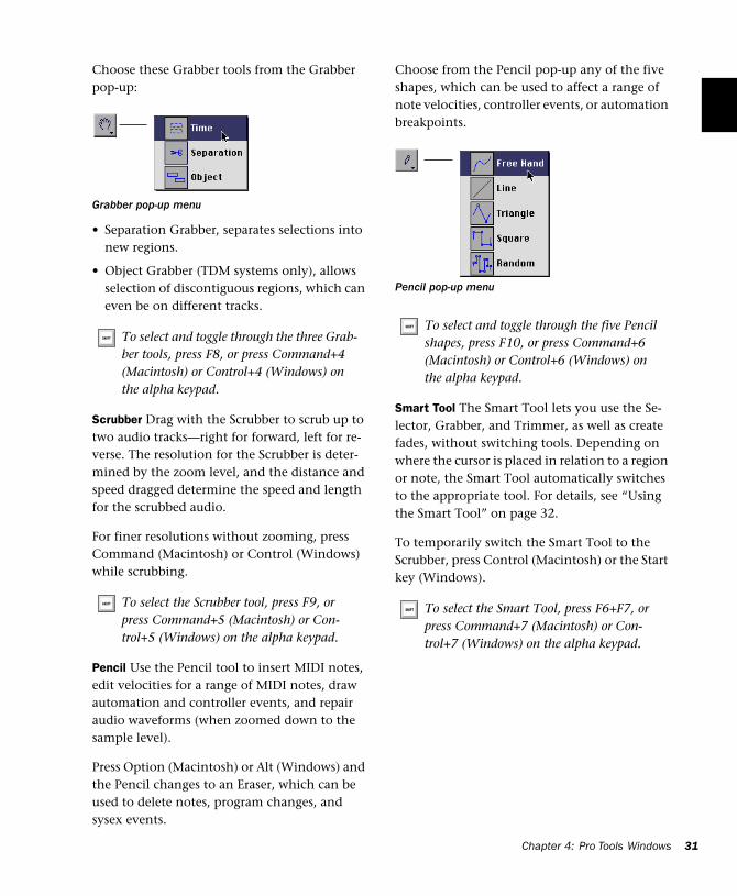
Choose these Grabber tools from the Grabber pop-up:
• Separation Grabber, separates selections into new regions.
• Object Grabber (TDM systems only), allows selection of discontiguous regions, which can even be on different tracks.
Scrubber Drag with the Scrubber to scrub up to two audio tracks—right for forward, left for re-verse. The resolution for the Scrubber is deter-mined by the zoom level, and the distance and speed dragged determine the speed and length for the scrubbed audio.
For finer resolutions without zooming, press Command (Macintosh) or Control (Windows) while scrubbing.
Pencil Use the Pencil tool to insert MIDI notes, edit velocities for a range of MIDI notes, draw automation and controller events, and repair audio waveforms (when zoomed down to the sample level).
Press Option (Macintosh) or Alt (Windows) and the Pencil changes to an Eraser, which can be used to delete notes, program changes, and sysex events.
Grabber pop-up menu
To select and toggle through the three Grab-ber tools, press F8, or press Command+4 (Macintosh) or Control+4 (Windows) on the alpha keypad.
To select the Scrubber tool, press F9, or press Command+5 (Macintosh) or Con-trol+5 (Windows) on the alpha keypad.
Choose from the Pencil pop-up any of the five shapes, which can be used to affect a range of note velocities, controller events, or automation breakpoints.
Smart Tool The Smart Tool lets you use the Se-lector, Grabber, and Trimmer, as well as create fades, without switching tools. Depending on where the cursor is placed in relation to a region or note, the Smart Tool automatically switches to the appropriate tool. For details, see “Using the Smart Tool” on page 32.
To temporarily switch the Smart Tool to the Scrubber, press Control (Macintosh) or the Start key (Windows).
Pencil pop-up menu
To select and toggle through the five Pencil shapes, press F10, or press Command+6 (Macintosh) or Control+6 (Windows) on the alpha keypad.
To select the Smart Tool, press F6+F7, or press Command+7 (Macintosh) or Con-trol+7 (Windows) on the alpha keypad.
Chapter 4: Pro Tools Windows 31
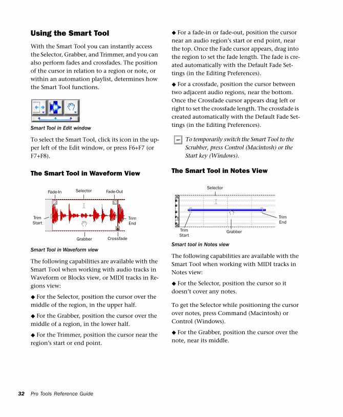
32
Using the Smart Tool
With the Smart Tool you can instantly access the Selector, Grabber, and Trimmer, and you can also perform fades and crossfades. The position of the cursor in relation to a region or note, or within an automation playlist, determines how the Smart Tool functions.
To select the Smart Tool, click its icon in the up-per left of the Edit window, or press F6+F7 (or F7+F8).
The Smart Tool in Waveform View
The following capabilities are available with the Smart Tool when working with audio tracks in Waveform or Blocks view, or MIDI tracks in Re-gions view:
◆ For the Selector, position the cursor over the middle of the region, in the upper half.
◆ For the Grabber, position the cursor over the middle of a region, in the lower half.
◆ For the Trimmer, position the cursor near the region’s start or end point.
Smart Tool in Edit window
Smart Tool in Waveform view
Fade-In Fade-OutSelector
Grabber
TrimStart
TrimEnd
Crossfade
Pro Tools Reference Guide
◆ For a fade-in or fade-out, position the cursor near an audio region’s start or end point, near the top. Once the Fade cursor appears, drag into the region to set the fade length. The fade is cre-ated automatically with the Default Fade Set-tings (in the Editing Preferences).
◆ For a crossfade, position the cursor between two adjacent audio regions, near the bottom. Once the Crossfade cursor appears drag left or right to set the crossfade length. The crossfade is created automatically with the Default Fade Set-tings (in the Editing Preferences).
The Smart Tool in Notes View
The following capabilities are available with the Smart Tool when working with MIDI tracks in Notes view:
◆ For the Selector, position the cursor so it doesn’t cover any notes.
To get the Selector while positioning the cursor over notes, press Command (Macintosh) or Control (Windows).
◆ For the Grabber, position the cursor over the note, near its middle.
To temporarily switch the Smart Tool to the Scrubber, press Control (Macintosh) or the Start key (Windows).
Smart tool in Notes view
Selector
GrabberTrimStart
TrimEnd
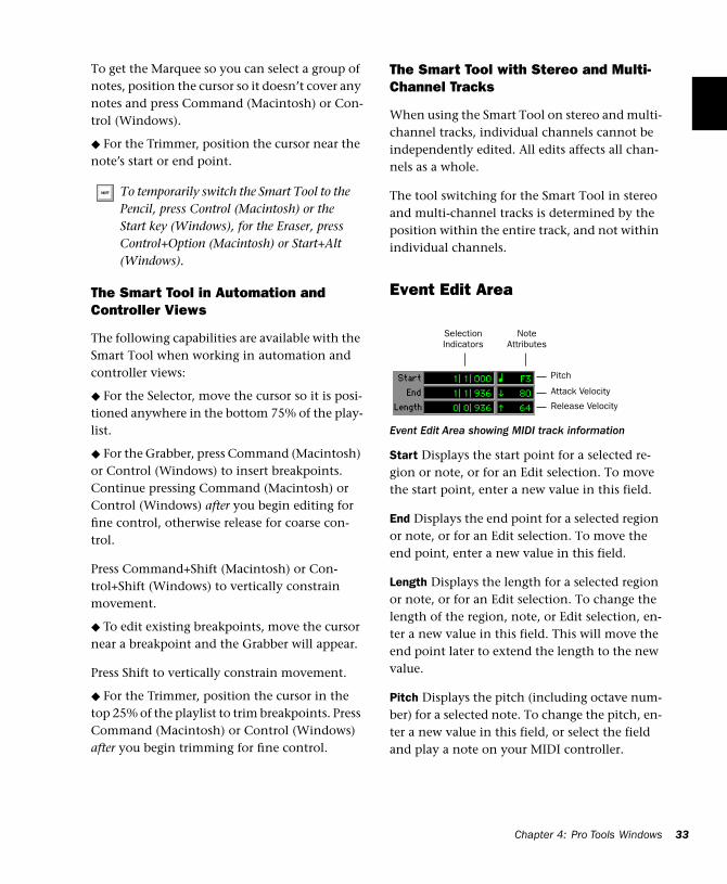
To get the Marquee so you can select a group of notes, position the cursor so it doesn’t cover any notes and press Command (Macintosh) or Con-trol (Windows).
◆ For the Trimmer, position the cursor near the note’s start or end point.
The Smart Tool in Automation and Controller Views
The following capabilities are available with the Smart Tool when working in automation and controller views:
◆ For the Selector, move the cursor so it is posi-tioned anywhere in the bottom 75% of the play-list.
◆ For the Grabber, press Command (Macintosh) or Control (Windows) to insert breakpoints. Continue pressing Command (Macintosh) or Control (Windows) after you begin editing for fine control, otherwise release for coarse con-trol.
Press Command+Shift (Macintosh) or Con-trol+Shift (Windows) to vertically constrain movement.
◆ To edit existing breakpoints, move the cursor near a breakpoint and the Grabber will appear.
Press Shift to vertically constrain movement.
◆ For the Trimmer, position the cursor in the top 25% of the playlist to trim breakpoints. Press Command (Macintosh) or Control (Windows) after you begin trimming for fine control.
To temporarily switch the Smart Tool to the Pencil, press Control (Macintosh) or the Start key (Windows), for the Eraser, press Control+Option (Macintosh) or Start+Alt (Windows).
The Smart Tool with Stereo and Multi-Channel Tracks
When using the Smart Tool on stereo and multi-channel tracks, individual channels cannot be independently edited. All edits affects all chan-nels as a whole.
The tool switching for the Smart Tool in stereo and multi-channel tracks is determined by the position within the entire track, and not within individual channels.
Event Edit Area
Start Displays the start point for a selected re-gion or note, or for an Edit selection. To move the start point, enter a new value in this field.
End Displays the end point for a selected region or note, or for an Edit selection. To move the end point, enter a new value in this field.
Length Displays the length for a selected region or note, or for an Edit selection. To change the length of the region, note, or Edit selection, en-ter a new value in this field. This will move the end point later to extend the length to the new value.
Pitch Displays the pitch (including octave num-ber) for a selected note. To change the pitch, en-ter a new value in this field, or select the field and play a note on your MIDI controller.
Event Edit Area showing MIDI track information
NoteAttributes
Pitch
Attack Velocity
Release Velocity
SelectionIndicators
Chap
ter 4: Pro Tools Windows 33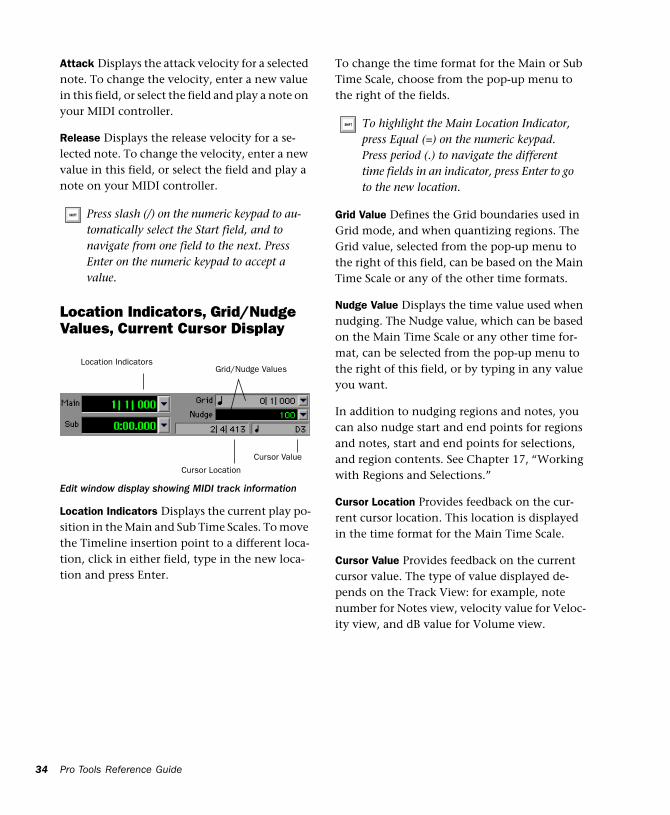
34
Attack Displays the attack velocity for a selected note. To change the velocity, enter a new value in this field, or select the field and play a note on your MIDI controller.
Release Displays the release velocity for a se-lected note. To change the velocity, enter a new value in this field, or select the field and play a note on your MIDI controller.
Location Indicators, Grid/Nudge Values, Current Cursor Display
Location Indicators Displays the current play po-sition in the Main and Sub Time Scales. To move the Timeline insertion point to a different loca-tion, click in either field, type in the new loca-tion and press Enter.
Press slash (/) on the numeric keypad to au-tomatically select the Start field, and to navigate from one field to the next. Press Enter on the numeric keypad to accept a value.
Edit window display showing MIDI track information
Cursor Location
Grid/Nudge ValuesLocation Indicators
Cursor Value
Pro Tools Reference Guide
To change the time format for the Main or Sub Time Scale, choose from the pop-up menu to the right of the fields.
Grid Value Defines the Grid boundaries used in Grid mode, and when quantizing regions. The Grid value, selected from the pop-up menu to the right of this field, can be based on the Main Time Scale or any of the other time formats.
Nudge Value Displays the time value used when nudging. The Nudge value, which can be based on the Main Time Scale or any other time for-mat, can be selected from the pop-up menu to the right of this field, or by typing in any value you want.
In addition to nudging regions and notes, you can also nudge start and end points for regions and notes, start and end points for selections, and region contents. See Chapter 17, “Working with Regions and Selections.”
Cursor Location Provides feedback on the cur-rent cursor location. This location is displayed in the time format for the Main Time Scale.
Cursor Value Provides feedback on the current cursor value. The type of value displayed de-pends on the Track View: for example, note number for Notes view, velocity value for Veloc-ity view, and dB value for Volume view.
To highlight the Main Location Indicator, press Equal (=) on the numeric keypad. Press period (.) to navigate the different time fields in an indicator, press Enter to go to the new location.
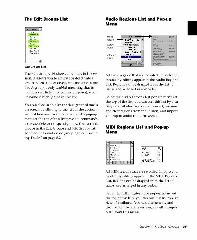
The Edit Groups List
The Edit Groups list shows all groups in the ses-sion. It allows you to activate or deactivate a group by selecting or deselecting its name in the list. A group is only enabled (meaning that its members are linked for editing purposes), when its name is highlighted in this list.
You can also use this list to select grouped tracks on-screen by clicking to the left of the dotted vertical line next to a group name. The pop-up menu at the top of this list provides commands to create, delete or suspend groups. You can link groups in the Edit Groups and Mix Groups lists. For more information on grouping, see “Group-ing Tracks” on page 85.
Edit Groups List
Audio Regions List and Pop-up Menu
All audio regions that are recorded, imported, or created by editing appear in the Audio Regions List. Regions can be dragged from the list to tracks and arranged in any order.
Using the Audio Regions List pop-up menu (at the top of the list) you can sort this list by a va-riety of attributes. You can also select, rename and clear regions from the session, and import and export audio from the session.
MIDI Regions List and Pop-up Menu
All MIDI regions that are recorded, imported, or created by editing appear in the MIDI Regions List. Regions can be dragged from the list to tracks and arranged in any order.
Using the MIDI Regions List pop-up menu (at the top of this list), you can sort this list by a va-riety of attributes. You can also rename and clear regions from the session, as well as import MIDI from this menu.
mono region
stereo region
selected region
Chapter 4: Pro Tools Windows 35
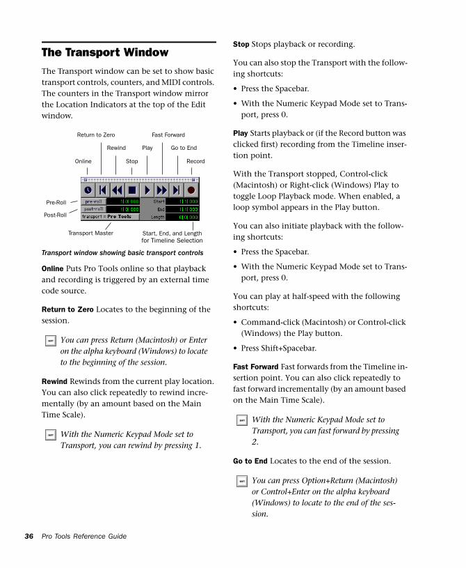
36
The Transport WindowThe Transport window can be set to show basic transport controls, counters, and MIDI controls. The counters in the Transport window mirror the Location Indicators at the top of the Edit window.
Online Puts Pro Tools online so that playback and recording is triggered by an external time code source.
Return to Zero Locates to the beginning of the session.
Rewind Rewinds from the current play location. You can also click repeatedly to rewind incre-mentally (by an amount based on the Main Time Scale).
Transport window showing basic transport controls
You can press Return (Macintosh) or Enter on the alpha keyboard (Windows) to locate to the beginning of the session.
With the Numeric Keypad Mode set to Transport, you can rewind by pressing 1.
Start, End, and Lengthfor Timeline Selection
Online
Rewind
Fast Forward
Stop
Play
Record
Return to Zero
Go to End
Pre-Roll
Transport Master
Post-Roll
Pro Tools Reference Guide
Stop Stops playback or recording.
You can also stop the Transport with the follow-ing shortcuts:
• Press the Spacebar.
• With the Numeric Keypad Mode set to Trans-port, press 0.
Play Starts playback or (if the Record button was clicked first) recording from the Timeline inser-tion point.
With the Transport stopped, Control-click (Macintosh) or Right-click (Windows) Play to toggle Loop Playback mode. When enabled, a loop symbol appears in the Play button.
You can also initiate playback with the follow-ing shortcuts:
• Press the Spacebar.
• With the Numeric Keypad Mode set to Trans-port, press 0.
You can play at half-speed with the following shortcuts:
• Command-click (Macintosh) or Control-click (Windows) the Play button.
• Press Shift+Spacebar.
Fast Forward Fast forwards from the Timeline in-sertion point. You can also click repeatedly to fast forward incrementally (by an amount based on the Main Time Scale).
Go to End Locates to the end of the session.
With the Numeric Keypad Mode set to Transport, you can fast forward by pressing 2.
You can press Option+Return (Macintosh) or Control+Enter on the alpha keyboard (Windows) to locate to the end of the ses-sion.
Record Arms Pro Tools for recording (the button flashes). Clicking Play then initiates recording.
With the Transport stopped, Control-click (Macintosh) or Right-click (Windows) Record to cycle through the four record modes. The Record button changes to indicate the currently selected mode: blank for Nondestructive, “D” for Destructive, a loop symbol for Loop Record, and “Q” for QuickPunch.
You can also begin recording with the following shortcuts:
• Press F12.
• Press Command+Spacebar (Macintosh) or Control+Spacebar (Windows).
• With the Numeric Keypad Mode set to Trans-port, press 3.
Pre-Roll Specifies the amount that plays before the beginning of a play or record range. Pre-roll is particularly useful in punch recording since it provides you with time to “catch the beat” be-fore reaching the punch-in point. To set the pre-roll amount, enter a new value in this field, or drag the Pre-Roll flag in the Main Timebase Ruler.
To enable pre-roll, click the Pre-Roll button to the left of the pre-roll field so it becomes high-lighted.
To initiate recording at half-speed, press Command+Shift+Spacebar (Macintosh) or Control+Shift+Spacebar (Windows).
Post-Roll Specifies the amount that plays after the end of a play or record range. Post-roll is use-ful in punch recording since playback continues after the punch-out point so you can check for a smooth transition to previously recorded mate-rial. To set the post-roll amount, enter a new value in this field, or drag the Post-Roll flag in the Main Timebase Ruler.
To enable post-roll, click the Post-Roll button to the left of the post-roll field so it becomes high-lighted.
Start Specifies the beginning of the play or record range. You can set the start point by en-tering a location in this field, or by dragging the corresponding Playback Marker in the Main Timebase Ruler.
End Specifies the end of the play or record range. You can set the end point by entering a location in this field, or by dragging the corresponding Playback Marker in the Main Timebase Ruler.
Length Specifies the length for the play or record range. You can set the length by entering a loca-tion in this field, or by selecting a range in any Timebase Ruler.
Transport Master Specifies the “master” for transport functions. Click this button and choose from the pop-up menu to select the Transport Master, which can be set to Pro Tools, Machine, MMC, and Remote. See “Using MIDI Machine Control” on page 479 for details.
When the Edit and Timeline selections are linked, you can drag in a track’s playlist to set the play and record range.
Chapter 4: Pro Tools Windows 37
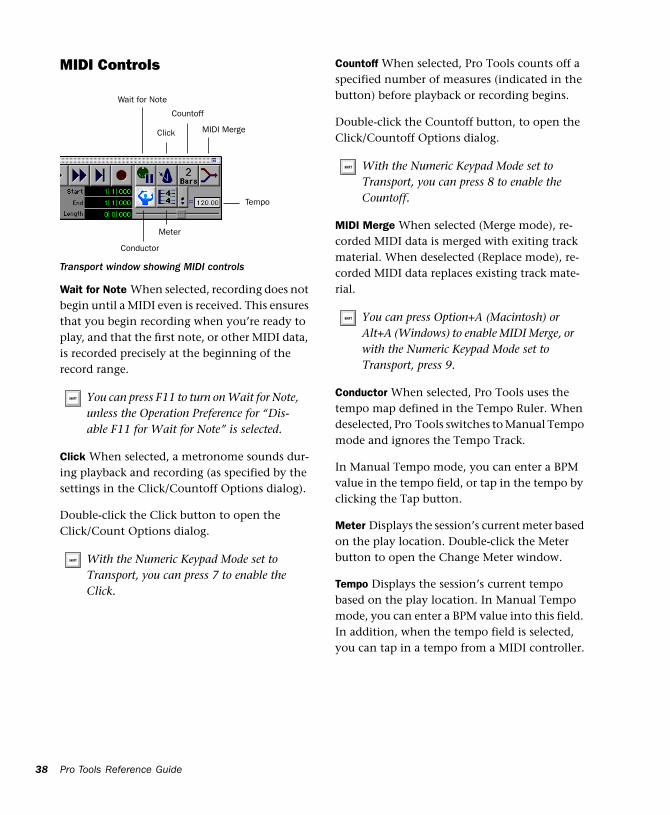
38
MIDI Controls
Wait for Note When selected, recording does not begin until a MIDI even is received. This ensures that you begin recording when you’re ready to play, and that the first note, or other MIDI data, is recorded precisely at the beginning of the record range.
Click When selected, a metronome sounds dur-ing playback and recording (as specified by the settings in the Click/Countoff Options dialog).
Double-click the Click button to open the Click/Count Options dialog.
Transport window showing MIDI controls
You can press F11 to turn on Wait for Note, unless the Operation Preference for “Dis-able F11 for Wait for Note” is selected.
With the Numeric Keypad Mode set to Transport, you can press 7 to enable the Click.
Conductor
Wait for Note
Meter
Countoff
Tempo
Click MIDI Merge
Pro Tools Reference Guide
Countoff When selected, Pro Tools counts off a specified number of measures (indicated in the button) before playback or recording begins.
Double-click the Countoff button, to open the Click/Countoff Options dialog.
MIDI Merge When selected (Merge mode), re-corded MIDI data is merged with exiting track material. When deselected (Replace mode), re-corded MIDI data replaces existing track mate-rial.
Conductor When selected, Pro Tools uses the tempo map defined in the Tempo Ruler. When deselected, Pro Tools switches to Manual Tempo mode and ignores the Tempo Track.
In Manual Tempo mode, you can enter a BPM value in the tempo field, or tap in the tempo by clicking the Tap button.
Meter Displays the session’s current meter based on the play location. Double-click the Meter button to open the Change Meter window.
Tempo Displays the session’s current tempo based on the play location. In Manual Tempo mode, you can enter a BPM value into this field. In addition, when the tempo field is selected, you can tap in a tempo from a MIDI controller.
With the Numeric Keypad Mode set to Transport, you can press 8 to enable the Countoff.
You can press Option+A (Macintosh) or Alt+A (Windows) to enable MIDI Merge, or with the Numeric Keypad Mode set to Transport, press 9.
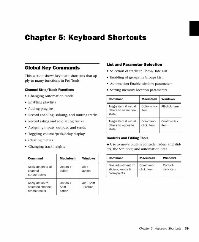
Chapter 5: Keyboard Shortcuts
Global Key CommandsThis section shows keyboard shortcuts that ap-ply to many functions in Pro Tools.
Channel Strip/Track Functions
• Changing Automation mode
• Enabling playlists
• Adding plug-ins
• Record enabling, soloing, and muting tracks
• Record safing and solo safing tracks
• Assigning inputs, outputs, and sends
• Toggling volume/peak/delay display
• Clearing meters
• Changing track heights
Command Macintosh Windows
Apply action to all channel strips/tracks
Option + action
Alt + action
Apply action to selected channel strips/tracks
Option + Shift + action
Alt + Shift + action
List and Parameter Selection
• Selection of tracks in Show/Hide List
• Enabling of groups in Groups List
• Automation Enable window parameters
• Setting memory location parameters
Controls and Editing Tools
◆ Use to move plug-in controls, faders and slid-ers, the Scrubber, and automation data
Command Macintosh Windows
Toggle item & set all others to same new state
Option-click item
Alt-click item
Toggle item & set all others to opposite state
Command-click item
Control-click item
Command Macintosh Windows
Fine adjustment of sliders, knobs & breakpoints
Command-click item
Control-click item
Chapter 5: Keyboard Shortcuts 39
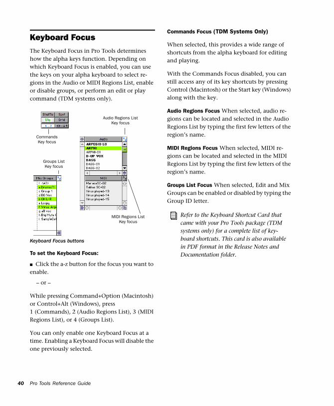
40
Keyboard FocusThe Keyboard Focus in Pro Tools determines how the alpha keys function. Depending on which Keyboard Focus is enabled, you can use the keys on your alpha keyboard to select re-gions in the Audio or MIDI Regions List, enable or disable groups, or perform an edit or play command (TDM systems only).
To set the Keyboard Focus:
■ Click the a-z button for the focus you want to enable.
– or –
While pressing Command+Option (Macintosh) or Control+Alt (Windows), press 1 (Commands), 2 (Audio Regions List), 3 (MIDI Regions List), or 4 (Groups List).
You can only enable one Keyboard Focus at a time. Enabling a Keyboard Focus will disable the one previously selected.
Keyboard Focus buttons
CommandsKey focus
Audio Regions ListKey focus
Groups ListKey focus
MIDI Regions ListKey focus
Pro Tools Reference Guide
Commands Focus (TDM Systems Only)
When selected, this provides a wide range of shortcuts from the alpha keyboard for editing and playing.
With the Commands Focus disabled, you can still access any of its key shortcuts by pressing Control (Macintosh) or the Start key (Windows) along with the key.
Audio Regions Focus When selected, audio re-gions can be located and selected in the Audio Regions List by typing the first few letters of the region’s name.
MIDI Regions Focus When selected, MIDI re-gions can be located and selected in the MIDI Regions List by typing the first few letters of the region’s name.
Groups List Focus When selected, Edit and Mix Groups can be enabled or disabled by typing the Group ID letter.
Refer to the Keyboard Shortcut Card that came with your Pro Tools package (TDM systems only) for a complete list of key-board shortcuts. This card is also available in PDF format in the Release Notes and Documentation folder.
Numeric Keypad ModesThe Operation preference for Numeric Keypad Mode determines how the numeric keypad functions.
No matter which Numeric Keypad Mode is se-lected, you can always use the numeric keypad to select and enter values in the Event Edit Area, Location Indicators, and Transport fields.
To set the Numeric Keypad Mode:
1 Choose Setups > Preferences and click Opera-tion.
2 Under the option for Numeric Keypad Mode, select on of the following modes, then click Done.
Classic
This mode emulates the way Pro Tools worked in versions earlier than 5.0. With the Numeric Keypad Mode set to Classic, you can:
• Play up to two tracks of audio in Shuttle Lock mode. Press Control (Macintosh) or the Start key (Windows), followed by 0-9 for different play speeds. Press Plus or Minus to reverse di-rection.
• Recall Memory Locations by typing the Mem-ory Location number, followed by period.
Transport
This mode allows you to set a number of record and play functions, and also operate the Trans-port from the numeric keypad.:
With the Numeric Keypad Mode set to Trans-port, you can also:
• Play up to two tracks of audio in Shuttle Lock mode. Press Control (Macintosh) or the Start key (Windows), followed by 0-9 for different play speeds. Press Plus or Minus to reverse di-rection.
• Recall Memory Locations by typing period, the Memory Location number, and period again.
Function Key
Click on/off 7
Countoff on/off 8
MIDI Merge/Replace mode 9
Loop Playback mode on/off 4
Loop Record mode on/off 5
QuickPunch mode on/off 6
Rewind 1
Fast Forward 2
Record 3
Play/Stop 0
Chapter 5: Keyboard Shortcuts 41
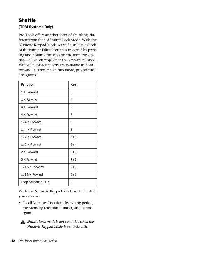
42
Shuttle(TDM Systems Only)
Pro Tools offers another form of shuttling, dif-ferent from that of Shuttle Lock Mode. With the Numeric Keypad Mode set to Shuttle, playback of the current Edit selection is triggered by press-ing and holding the keys on the numeric key-pad—playback stops once the keys are released. Various playback speeds are available in both forward and reverse. In this mode, pre/post-roll are ignored.:
With the Numeric Keypad Mode set to Shuttle, you can also:
• Recall Memory Locations by typing period, the Memory Location number, and period again.
Function Key
1 X Forward 6
1 X Rewind 4
4 X Forward 9
4 X Rewind 7
1/4 X Forward 3
1/4 X Rewind 1
1/2 X Forward 5+6
1/2 X Rewind 5+4
2 X Forward 8+9
2 X Rewind 8+7
1/16 X Forward 2+3
1/16 X Rewind 2+1
Loop Selection (1 X) 0
Shuttle Lock mode is not available when the Numeric Keypad Mode is set to Shuttle.
Pro Tools Reference Guide
Part II: Sessions & Tracks
43

44
Chapter 6: Sessions
This chapter covers some of the basics of start-ing a project in Pro Tools, including how to set up and save a Pro Tools session.
Starting Up Your SystemIn order for the components of your Pro Tools system to communicate properly with each other, you need to start them up in a specific or-der.
Start your Pro Tools system in this order:
1 For TDM systems with an expansion chassis, turn on the expansion chassis.
2 Turn on external hard drives, if any. Wait ap-proximately ten seconds for them to spin up to speed.
3 Turn on any MIDI interfaces and devices.
4 For TDM systems, turn on Pro Tools audio in-terfaces. Wait at least ten seconds for them to initialize.
If you launch Pro Tools without turning on your audio interfaces, you will be prompted to turn them on. Allow about ten seconds for audio in-terfaces to power-up cycle before clicking OK.
5 Turn on your computer.
Once you have quit Pro Tools, shut down your Pro Tools system in this order:
1 For TDM systems, turn off audio interfaces.
2 For TDM systems with an expansion chassis, turn off the expansion chassis.
3 Turn off your computer.
4 Turn off any MIDI interfaces and devices.
5 Turn off external hard drives.
Configuring Your SystemWhen you first use Pro Tools, or when you change the physical input and output scheme for your system, you must configure the Hard-ware Setup in Pro Tools. This ensures that your audio hardware is appropriately configured and available in Pro Tools.
Host and RTAS Processing
Pro Tools LE uses host (CPU) processing to pro-vide audio track recording, playback, mixing, and effects processing. Pro Tools TDM can also use host processing to run RTAS plug-ins for ef-fects processing.
Pro Tools hardware setup allows you to set a hardware buffer and allocate a percentage of CPU resources for these tasks.
Chapter 6: Sessions 45
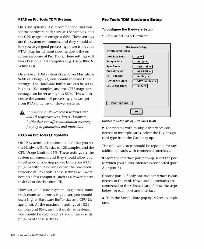
46
RTAS on Pro Tools TDM Systems
On TDM systems, it is recommended that you set the hardware buffer size at 128 samples, and the CPU usage percentage at 65%. These settings are the system minimums, and they should al-low you to get good processing power from your RTAS plug-ins without slowing down the on-screen response of Pro Tools. These settings will work best on a fast computer (e.g. G4 or Blue & White G3).
On a slower TDM system like a Power Macintosh 9600 or a beige G3, you should increase these settings. The Hardware Buffer size can be set as high as 1024 samples, and the CPU usage per-centage can be set as high as 85%. This will in-crease the amount of processing you can get from RTAS plug-ins on slower systems.
RTAS on Pro Tools LE Systems
On LE systems, it is recommended that you set the Hardware Buffer size to 128 samples, and the CPU Usage Limit to 65%. These settings are the system minimums, and they should allow you to get good processing power from your RTAS plug-ins without slowing down the on-screen response of Pro Tools. These settings will work best on a fast computer (such as a Power Macin-tosh G4 or fast Pentium III).
However, on a slower system, to get maximum track count and processing power, you should use a higher Hardware Buffer size and CPU Us-age Limit. At the maximum settings of 1024 samples and 85%, on most qualified systems, you should be able to get 24 audio tracks with plug-ins at these settings.
In addition to slower screen redraws and and UI responsiveness, larger Hardware Buffer sizes can affect automation accuracy for plug-in parameters and mute data.
Pro Tools Reference Guide
Pro Tools TDM Hardware Setup
To configure the Hardware Setup:
1 Choose Setups > Hardware.
2 For systems with multiple interfaces con-nected to multiple cards, select the Digidesign card type from the Card pop-up.
The following steps should be repeated for any additional cards with connected interfaces.
3 From the Interface port pop-up, select the port to which your audio interface is connected (port A or port B).
Choose port A if only one audio interface is con-nected to the card. If two audio interfaces are connected to the selected card, follow the steps below for each port and interface.
4 From the Sample Rate pop-up, select a sample rate.
Hardware Setup dialog (Pro Tools TDM)
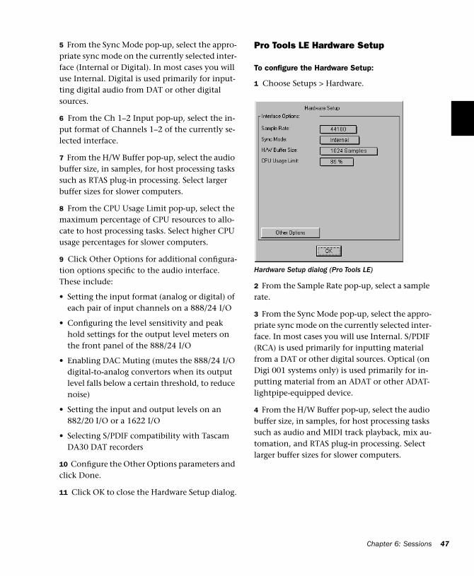
5 From the Sync Mode pop-up, select the appro-priate sync mode on the currently selected inter-face (Internal or Digital). In most cases you will use Internal. Digital is used primarily for input-ting digital audio from DAT or other digital sources.
6 From the Ch 1–2 Input pop-up, select the in-put format of Channels 1–2 of the currently se-lected interface.
7 From the H/W Buffer pop-up, select the audio buffer size, in samples, for host processing tasks such as RTAS plug-in processing. Select larger buffer sizes for slower computers.
8 From the CPU Usage Limit pop-up, select the maximum percentage of CPU resources to allo-cate to host processing tasks. Select higher CPU usage percentages for slower computers.
9 Click Other Options for additional configura-tion options specific to the audio interface. These include:
• Setting the input format (analog or digital) of each pair of input channels on a 888/24 I/O
• Configuring the level sensitivity and peak hold settings for the output level meters on the front panel of the 888/24 I/O
• Enabling DAC Muting (mutes the 888/24 I/O digital-to-analog convertors when its output level falls below a certain threshold, to reduce noise)
• Setting the input and output levels on an 882/20 I/O or a 1622 I/O
• Selecting S/PDIF compatibility with Tascam DA30 DAT recorders
10 Configure the Other Options parameters and click Done.
11 Click OK to close the Hardware Setup dialog.
Pro Tools LE Hardware Setup
To configure the Hardware Setup:
1 Choose Setups > Hardware.
2 From the Sample Rate pop-up, select a sample rate.
3 From the Sync Mode pop-up, select the appro-priate sync mode on the currently selected inter-face. In most cases you will use Internal. S/PDIF (RCA) is used primarily for inputting material from a DAT or other digital sources. Optical (on Digi 001 systems only) is used primarily for in-putting material from an ADAT or other ADAT-lightpipe-equipped device.
4 From the H/W Buffer pop-up, select the audio buffer size, in samples, for host processing tasks such as audio and MIDI track playback, mix au-tomation, and RTAS plug-in processing. Select larger buffer sizes for slower computers.
Hardware Setup dialog (Pro Tools LE)
Chapter 6: Sessions 47
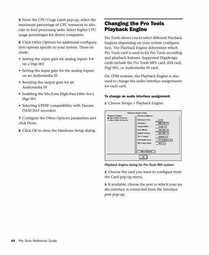
48
5 From the CPU Usage Limit pop-up, select the maximum percentage of CPU resources to allo-cate to host processing tasks. Select higher CPU usage percentages for slower computers.
6 Click Other Options for additional configura-tion options specific to your system. These in-clude:
• Setting the input gain for analog inputs 3-8 on a Digi 001
• Setting the input gain for the analog inputs on an Audiomedia III
• Boosting the output gain for an Audiomedia III
• Enabling the Mic/Line High-Pass Filter for a Digi 001
• Selecting S/PDIF compatibility with Tascam DA30 DAT recorders
7 Configure the Other Options parameters and click Done.
8 Click OK to close the Hardware Setup dialog.
Pro Tools Reference Guide
Changing the Pro Tools Playback EnginePro Tools allows you to select different Playback Engines depending on your system configura-tion. The Playback Engine determines which Pro Tools card is used to for Pro Tools recording and playback features. Supported Digidesign cards include the Pro Tools MIX card, d24 card, Digi 001, or Audiomedia III card.
On TDM systems, the Playback Engine is also used to change the audio interface assignments for each card.
To change an audio interface assignment:
1 Choose Setups > Playback Engine.
2 Choose the card you want to configure from the Card pop-up menu.
3 If available, choose the port to which your au-dio interface is connected from the Interface port pop-up.
Playback Engine dialog for Pro Tools MIX system
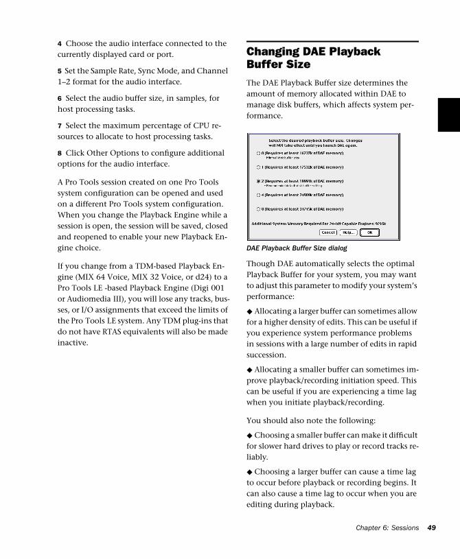
4 Choose the audio interface connected to the currently displayed card or port.
5 Set the Sample Rate, Sync Mode, and Channel 1–2 format for the audio interface.
6 Select the audio buffer size, in samples, for host processing tasks.
7 Select the maximum percentage of CPU re-sources to allocate to host processing tasks.
8 Click Other Options to configure additional options for the audio interface.
A Pro Tools session created on one Pro Tools system configuration can be opened and used on a different Pro Tools system configuration. When you change the Playback Engine while a session is open, the session will be saved, closed and reopened to enable your new Playback En-gine choice.
If you change from a TDM-based Playback En-gine (MIX 64 Voice, MIX 32 Voice, or d24) to a Pro Tools LE -based Playback Engine (Digi 001 or Audiomedia III), you will lose any tracks, bus-ses, or I/O assignments that exceed the limits of the Pro Tools LE system. Any TDM plug-ins that do not have RTAS equivalents will also be made inactive.
Changing DAE Playback Buffer SizeThe DAE Playback Buffer size determines the amount of memory allocated within DAE to manage disk buffers, which affects system per-formance.
Though DAE automatically selects the optimal Playback Buffer for your system, you may want to adjust this parameter to modify your system’s performance:
◆ Allocating a larger buffer can sometimes allow for a higher density of edits. This can be useful if you experience system performance problems in sessions with a large number of edits in rapid succession.
◆ Allocating a smaller buffer can sometimes im-prove playback/recording initiation speed. This can be useful if you are experiencing a time lag when you initiate playback/recording.
You should also note the following:
◆ Choosing a smaller buffer can make it difficult for slower hard drives to play or record tracks re-liably.
◆ Choosing a larger buffer can cause a time lag to occur before playback or recording begins. It can also cause a time lag to occur when you are editing during playback.
DAE Playback Buffer Size dialog
Chapter 6: Sessions 49
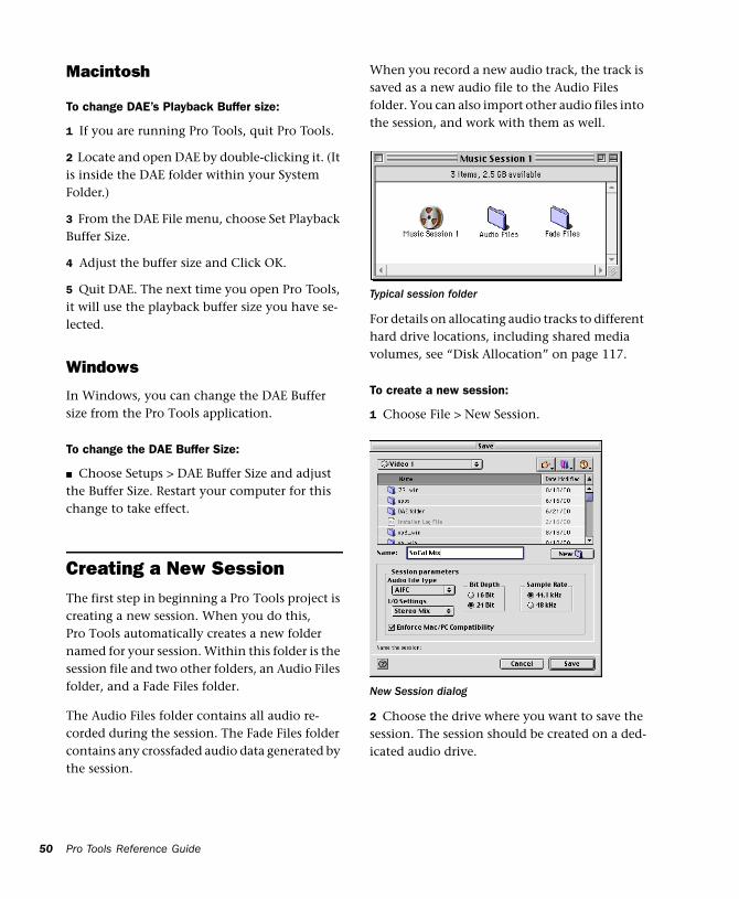
50
Macintosh
To change DAE’s Playback Buffer size:
1 If you are running Pro Tools, quit Pro Tools.
2 Locate and open DAE by double-clicking it. (It is inside the DAE folder within your System Folder.)
3 From the DAE File menu, choose Set Playback Buffer Size.
4 Adjust the buffer size and Click OK.
5 Quit DAE. The next time you open Pro Tools, it will use the playback buffer size you have se-lected.
Windows
In Windows, you can change the DAE Buffer size from the Pro Tools application.
To change the DAE Buffer Size:
■ Choose Setups > DAE Buffer Size and adjust the Buffer Size. Restart your computer for this change to take effect.
Creating a New SessionThe first step in beginning a Pro Tools project is creating a new session. When you do this, Pro Tools automatically creates a new folder named for your session. Within this folder is the session file and two other folders, an Audio Files folder, and a Fade Files folder.
The Audio Files folder contains all audio re-corded during the session. The Fade Files folder contains any crossfaded audio data generated by the session.
Pro Tools Reference Guide
When you record a new audio track, the track is saved as a new audio file to the Audio Files folder. You can also import other audio files into the session, and work with them as well.
For details on allocating audio tracks to different hard drive locations, including shared media volumes, see “Disk Allocation” on page 117.
To create a new session:
1 Choose File > New Session.
2 Choose the drive where you want to save the session. The session should be created on a ded-icated audio drive.
Typical session folder
New Session dialog
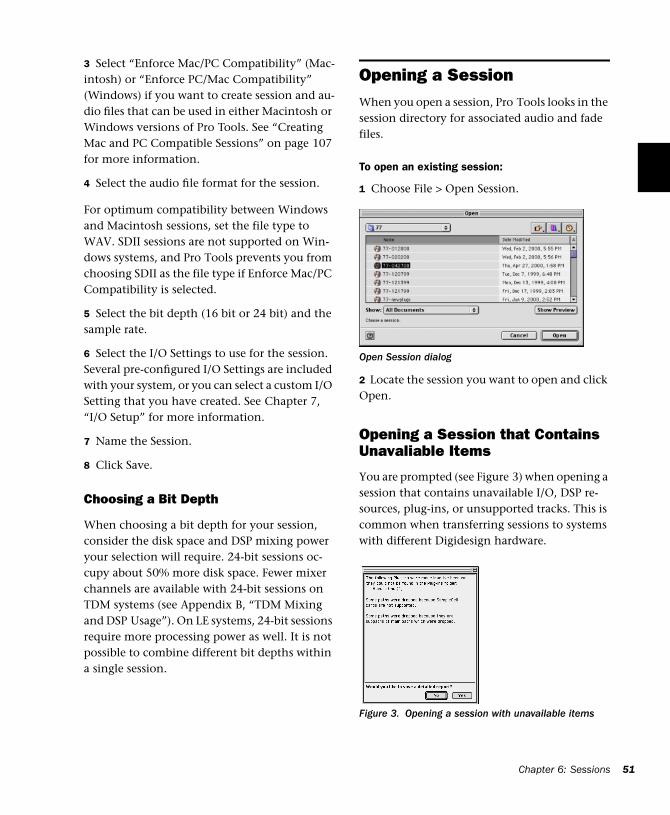
3 Select “Enforce Mac/PC Compatibility” (Mac-intosh) or “Enforce PC/Mac Compatibility” (Windows) if you want to create session and au-dio files that can be used in either Macintosh or Windows versions of Pro Tools. See “Creating Mac and PC Compatible Sessions” on page 107 for more information.
4 Select the audio file format for the session.
For optimum compatibility between Windows and Macintosh sessions, set the file type to WAV. SDII sessions are not supported on Win-dows systems, and Pro Tools prevents you from choosing SDII as the file type if Enforce Mac/PC Compatibility is selected.
5 Select the bit depth (16 bit or 24 bit) and the sample rate.
6 Select the I/O Settings to use for the session. Several pre-configured I/O Settings are included with your system, or you can select a custom I/O Setting that you have created. See Chapter 7, “I/O Setup” for more information.
7 Name the Session.
8 Click Save.
Choosing a Bit Depth
When choosing a bit depth for your session, consider the disk space and DSP mixing power your selection will require. 24-bit sessions oc-cupy about 50% more disk space. Fewer mixer channels are available with 24-bit sessions on TDM systems (see Appendix B, “TDM Mixing and DSP Usage”). On LE systems, 24-bit sessions require more processing power as well. It is not possible to combine different bit depths within a single session.
Opening a SessionWhen you open a session, Pro Tools looks in the session directory for associated audio and fade files.
To open an existing session:
1 Choose File > Open Session.
2 Locate the session you want to open and click Open.
Opening a Session that Contains Unavaliable Items
You are prompted (see Figure 3) when opening a session that contains unavailable I/O, DSP re-sources, plug-ins, or unsupported tracks. This is common when transferring sessions to systems with different Digidesign hardware.
Open Session dialog
Figure 3. Opening a session with unavailable items
Chapter 6: Sessions 51
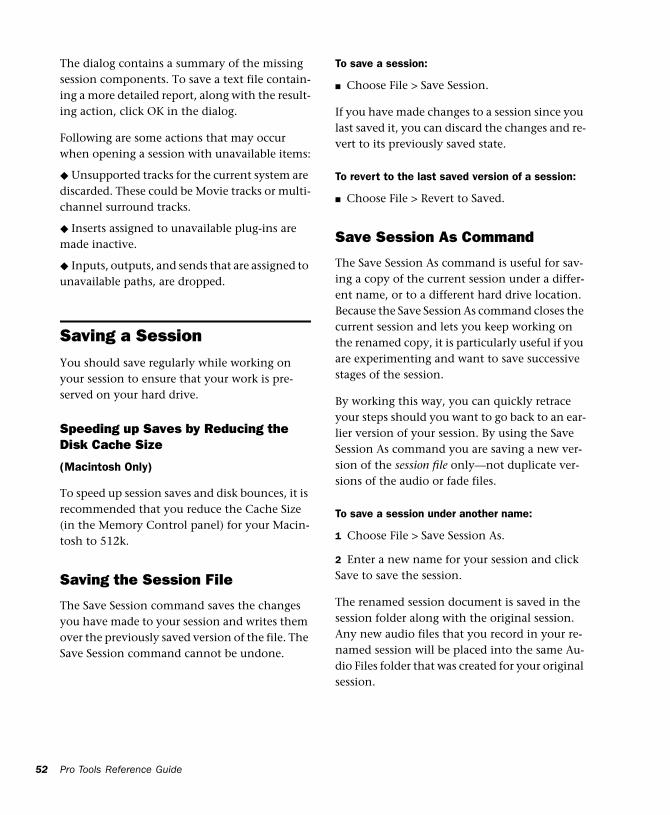
52
The dialog contains a summary of the missing session components. To save a text file contain-ing a more detailed report, along with the result-ing action, click OK in the dialog.
Following are some actions that may occur when opening a session with unavailable items:
◆ Unsupported tracks for the current system are discarded. These could be Movie tracks or multi-channel surround tracks.
◆ Inserts assigned to unavailable plug-ins are made inactive.
◆ Inputs, outputs, and sends that are assigned to unavailable paths, are dropped.
Saving a SessionYou should save regularly while working on your session to ensure that your work is pre-served on your hard drive.
Speeding up Saves by Reducing the Disk Cache Size
(Macintosh Only)
To speed up session saves and disk bounces, it is recommended that you reduce the Cache Size (in the Memory Control panel) for your Macin-tosh to 512k.
Saving the Session File
The Save Session command saves the changes you have made to your session and writes them over the previously saved version of the file. The Save Session command cannot be undone.
Pro Tools Reference Guide
To save a session:
■ Choose File > Save Session.
If you have made changes to a session since you last saved it, you can discard the changes and re-vert to its previously saved state.
To revert to the last saved version of a session:
■ Choose File > Revert to Saved.
Save Session As Command
The Save Session As command is useful for sav-ing a copy of the current session under a differ-ent name, or to a different hard drive location. Because the Save Session As command closes the current session and lets you keep working on the renamed copy, it is particularly useful if you are experimenting and want to save successive stages of the session.
By working this way, you can quickly retrace your steps should you want to go back to an ear-lier version of your session. By using the Save Session As command you are saving a new ver-sion of the session file only—not duplicate ver-sions of the audio or fade files.
To save a session under another name:
1 Choose File > Save Session As.
2 Enter a new name for your session and click Save to save the session.
The renamed session document is saved in the session folder along with the original session. Any new audio files that you record in your re-named session will be placed into the same Au-dio Files folder that was created for your original session.
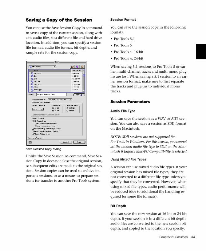
Saving a Copy of the Session
You can use the Save Session Copy In command to save a copy of the current session, along with a its audio files, to a different file and hard drive location. In addition, you can specify a session file format, audio file format, bit depth, and sample rate for the session copy.
Unlike the Save Session As command, Save Ses-sion Copy In does not close the original session, so subsequent edits are made to the original ses-sion. Session copies can be used to archive im-portant sessions, or as a means to prepare ses-sions for transfer to another Pro Tools system.
Save Session Copy dialog
Session Format
You can save the session copy in the following formats:
• Pro Tools 5.1
• Pro Tools 5
• Pro Tools 4. 16-bit
• Pro Tools 4, 24-bit
When saving 5.1 sessions to Pro Tools 5 or ear-lier, multi-channel tracks and multi-mono plug-ins are lost. When saving a 5.1 session to an ear-lier session format, make sure to first separate the tracks and plug-ins to individual mono tracks.
Session Parameters
Audio File Type
You can save the session as a WAV or AIFF ses-sion. You can also save a session as SDII format on the Macintosh.
NOTE: SDII sessions are not supported for Pro Tools in Windows. For this reason, you cannot set the session audio file type to SDII on the Mac-intosh if Enforce Mac/PC Compatibility is selected.
Using Mixed File Types
A session can use mixed audio file types. If your original session has mixed file types, they are not converted to a different file type unless you specify that they be converted. However, when using mixed file types, audio performance will be reduced (due to additional file handling re-quired for some file formats).
Bit Depth
You can save the new session at 16-bit or 24-bit depth. If your session is in a different bit depth, audio files are converted to the new session bit depth, and copied to the location you specify.
Chapter 6: Sessions 53
54
Sample Rate
You can save the new session at 44.1 kHz or 48 kHz sample rate. If your session is at a differ-ent sample rate, audio files are converted to the new session sample rate, and copied to the loca-tion you specify.
Enforce Mac/PC Compatibility (Macintosh)Enforce PC/Mac Compatibility (Windows)
This setting forces Macintosh or Windows ver-sions of Pro Tools to create sessions and audio files that are usable on both platforms. For more information, see “Creating Mac and PC Com-patible Sessions” on page 107.
Items to Copy
Audio Files and Session Plug-In Settings Folder
When this option is selected, all audio files and the session’s Plug-In Settings Folder are copied to the new location. The references to these plug-in settings in the session are redirected to point to the copied files.
This setting is automatically selected if you are changing bit depth or sample rate, or copying a session on the Macintosh from SDII format to AIFF or WAV format with Enforce Mac/PC Com-patibility selected.
Force Audio Files to Native Session Type
This option ensures that all files in the new ses-sion are in the session file type you select, by converting files of different types to the session’s file format. Use this setting to avoid the reduced performance of a session with mixed file types.
This setting is automatically selected if you are changing bit depth or sample rate, or copying a session on the Macintosh from SDII format to AIFF or WAV format with Enforce Mac/PC Com-patibility selected.
Pro Tools Reference Guide
Don’t Copy Fade Files
With this option selected, Fade Files are not cop-ied to the new session Fade Files folder. When the session is launched, the Find Files dialog will prompt you to locate Fade Files. You can either locate the existing fades using the find file dia-log, or Skip All to let Pro Tools recreate the fades from the session document.
Root Plug-In Settings Folder
When this option is selected, the contents of the root-level Plug-In Settings Folder are copied into a folder named Place in Root Settings Folder, indi-cating that these files will need to be moved to the root level plug-in settings folder on the des-tination system before you can use them. The references to these settings files in the session are not redirected to point to the copied files.
Movie/Video Files (Macintosh Only)
When this option is selected, session movie files (QuickTime video files or AVoption or AVoption XL video files) are copied to the new location, and session references are updated to point to the copied movie files.
To save a session copy in a new location:
1 Choose File > Save Session Copy In.
2 Select “Enforce Mac/PC Compatibility” (Mac-intosh) or “Enforce PC/Mac Compatibility” (Windows) if you want to create session and au-dio files that can be used in either Macintosh or Windows versions of Pro Tools. See “Creating Mac and PC Compatible Sessions” on page 107 for more information.
3 Choose a destination and type a name for the new session file.
4 Select the session file type for the session copy.
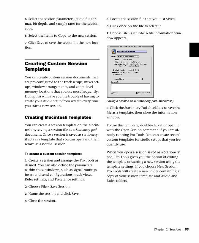
5 Select the session parameters (audio file for-mat, bit depth, and sample rate) for the session copy.
6 Select the Items to Copy to the new session.
7 Click Save to save the session in the new loca-tion.
Creating Custom Session TemplatesYou can create custom session documents that are pre-configured to the track setups, mixer set-ups, window arrangements, and zoom level memory locations that you use most frequently. Doing this will save you the trouble of having to create your studio setup from scratch every time you start a new session.
Creating Macintosh Templates
You can create a session template on the Macin-tosh by saving a session file as a Stationery pad document. Once a session is saved as stationery, it acts as a template that you can open and then resave as a normal session.
To create a custom session template:
1 Create a session and arrange the Pro Tools as desired. You can also define the parameters within these windows, such as signal routings, insert and send configurations, track views, Ruler settings, and Preference settings.
2 Choose File > Save Session.
3 Name the session and click Save.
4 Close the session.
5 Locate the session file that you just saved.
6 Click once on the file to select it.
7 Choose File > Get Info. A file information win-dow appears.
8 Click the Stationery Pad check box to save the file as a template, then close the information window.
To use this template, double-click it or open it with the Open Session command if you are al-ready running Pro Tools. You can create several custom templates for studio setups that you fre-quently use.
When you open a session saved as a Stationery pad, Pro Tools gives you the option of editing the template or starting a new session using the template settings. If you choose New Session, Pro Tools will create a new folder containing a copy of your session template and Audio and Fades folders.
Saving a session as a Stationery pad (Macintosh)
Chapter 6: Sessions 55
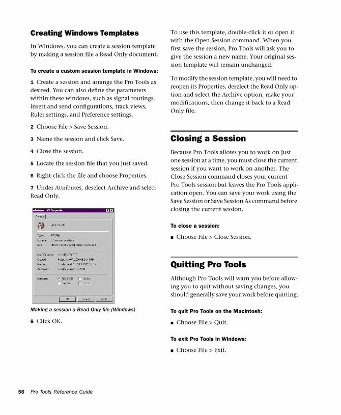
56
Creating Windows Templates
In Windows, you can create a session template by making a session file a Read Only document.
To create a custom session template in Windows:
1 Create a session and arrange the Pro Tools as desired. You can also define the parameters within these windows, such as signal routings, insert and send configurations, track views, Ruler settings, and Preference settings.
2 Choose File > Save Session.
3 Name the session and click Save.
4 Close the session.
5 Locate the session file that you just saved.
6 Right-click the file and choose Properties.
7 Under Attributes, deselect Archive and select Read Only.
8 Click OK.
Making a session a Read Only file (Windows)
Pro Tools Reference Guide
To use this template, double-click it or open it with the Open Session command. When you first save the session, Pro Tools will ask you to give the session a new name. Your original ses-sion template will remain unchanged.
To modify the session template, you will need to reopen its Properties, deselect the Read Only op-tion and select the Archive option, make your modifications, then change it back to a Read Only file.
Closing a SessionBecause Pro Tools allows you to work on just one session at a time, you must close the current session if you want to work on another. The Close Session command closes your current Pro Tools session but leaves the Pro Tools appli-cation open. You can save your work using the Save Session or Save Session As command before closing the current session.
To close a session:
■ Choose File > Close Session.
Quitting Pro ToolsAlthough Pro Tools will warn you before allow-ing you to quit without saving changes, you should generally save your work before quitting.
To quit Pro Tools on the Macintosh:
■ Choose File > Quit.
To exit Pro Tools in Windows:
■ Choose File > Exit.
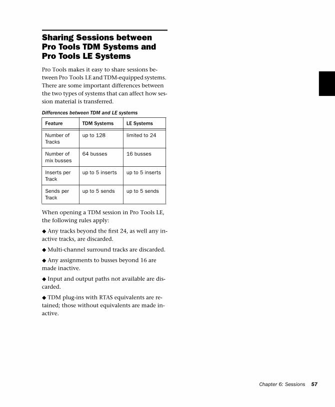
Sharing Sessions between Pro Tools TDM Systems and Pro Tools LE SystemsPro Tools makes it easy to share sessions be-tween Pro Tools LE and TDM-equipped systems. There are some important differences between the two types of systems that can affect how ses-sion material is transferred.
When opening a TDM session in Pro Tools LE, the following rules apply:
◆ Any tracks beyond the first 24, as well any in-active tracks, are discarded.
◆ Multi-channel surround tracks are discarded.
◆ Any assignments to busses beyond 16 are made inactive.
◆ Input and output paths not available are dis-carded.
◆ TDM plug-ins with RTAS equivalents are re-tained; those without equivalents are made in-active.
Differences between TDM and LE systems
Feature TDM Systems LE Systems
Number of Tracks
up to 128 limited to 24
Number of mix busses
64 busses 16 busses
Inserts per Track
up to 5 inserts up to 5 inserts
Sends per Track
up to 5 sends up to 5 sends
Chapter 6: Sessions 57

58
Pro Tools Reference Guide
Chapter 7: I/O Setup
The I/O Setup dialog provides tools to label, for-mat, and map Pro Tools input, output, insert, and buss signal paths.
What is I/O Setup?
During sessions, audio is routed using the track input, output, insert, plug-in, and send selec-tors. The selectors let you assign tracks to hard-ware outputs and inputs, internal busses, and other Pro Tools signal paths. The signal path choices available in Pro Tools sessions are based on the current I/O Setup.
The I/O Setup dialog lets you name and define input, output, insert, buss, and SampleCell path so that Pro Tools best suits the needs of your projects. For example, renaming Input 1 to Kick In. (SampleCell paths are available on TDM-equipped systems only.)
Understanding Paths and I/O SetupA path is a logical grouping of multiple inputs, outputs or busses that has a single name and (channel) format. In Pro Tools, paths are similar to stems, known to the film and video industries (see “Stems and Stem Mixes” on page 61 for more information).
Each Pro Tools system can have a different I/O Setup configuration, determined by:
• Whether it is a Pro Tools LE system, or a TDM-equipped Pro Tools system
• The number and types of audio interfaces (TDM systems only)
• The Mixer plug-in currently installed (Sur-round, 24-bit, or 16-bit)
Each Pro Tools session retains its path configu-rations as I/O Settings. The I/O Settings saved with the session are loaded into Pro Tools auto-matically when the session is opened. Unavail-able items, including hardware, paths, or re-quired resources) remain in the session as inactive items (see “Active and Inactive Paths” on page 68).
Chapter 7: I/O Setup 59
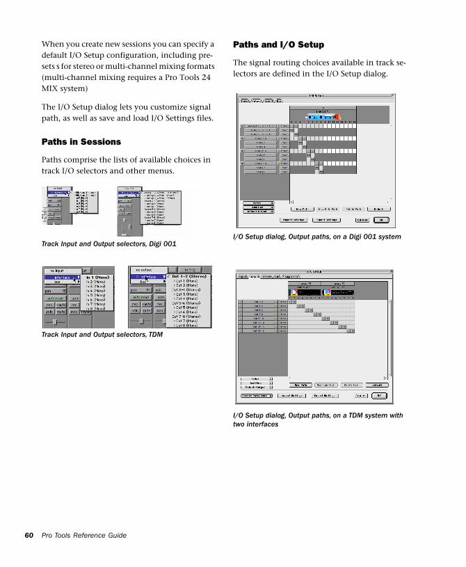
60
When you create new sessions you can specify a default I/O Setup configuration, including pre-sets s for stereo or multi-channel mixing formats (multi-channel mixing requires a Pro Tools 24 MIX system)
The I/O Setup dialog lets you customize signal path, as well as save and load I/O Settings files.
Paths in Sessions
Paths comprise the lists of available choices in track I/O selectors and other menus.
Track Input and Output selectors, Digi 001
Track Input and Output selectors, TDM
Pro Tools Reference Guide
Paths and I/O Setup
The signal routing choices available in track se-lectors are defined in the I/O Setup dialog.
I/O Setup dialog, Output paths, on a Digi 001 system
I/O Setup dialog, Output paths, on a TDM system with two interfaces
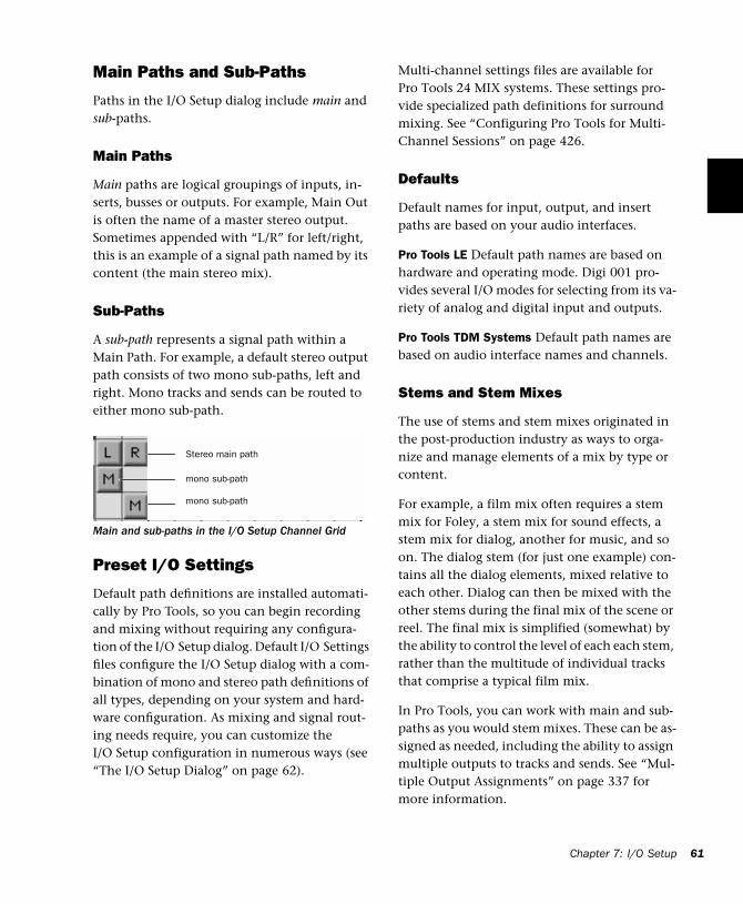
Main Paths and Sub-Paths
Paths in the I/O Setup dialog include main and sub-paths.
Main Paths
Main paths are logical groupings of inputs, in-serts, busses or outputs. For example, Main Out is often the name of a master stereo output. Sometimes appended with “L/R” for left/right, this is an example of a signal path named by its content (the main stereo mix).
Sub-Paths
A sub-path represents a signal path within a Main Path. For example, a default stereo output path consists of two mono sub-paths, left and right. Mono tracks and sends can be routed to either mono sub-path.
Preset I/O Settings
Default path definitions are installed automati-cally by Pro Tools, so you can begin recording and mixing without requiring any configura-tion of the I/O Setup dialog. Default I/O Settings files configure the I/O Setup dialog with a com-bination of mono and stereo path definitions of all types, depending on your system and hard-ware configuration. As mixing and signal rout-ing needs require, you can customize the I/O Setup configuration in numerous ways (see “The I/O Setup Dialog” on page 62).
Main and sub-paths in the I/O Setup Channel Grid
Stereo main path
mono sub-path
mono sub-path
Multi-channel settings files are available for Pro Tools 24 MIX systems. These settings pro-vide specialized path definitions for surround mixing. See “Configuring Pro Tools for Multi-Channel Sessions” on page 426.
Defaults
Default names for input, output, and insert paths are based on your audio interfaces.
Pro Tools LE Default path names are based on hardware and operating mode. Digi 001 pro-vides several I/O modes for selecting from its va-riety of analog and digital input and outputs.
Pro Tools TDM Systems Default path names are based on audio interface names and channels.
Stems and Stem Mixes
The use of stems and stem mixes originated in the post-production industry as ways to orga-nize and manage elements of a mix by type or content.
For example, a film mix often requires a stem mix for Foley, a stem mix for sound effects, a stem mix for dialog, another for music, and so on. The dialog stem (for just one example) con-tains all the dialog elements, mixed relative to each other. Dialog can then be mixed with the other stems during the final mix of the scene or reel. The final mix is simplified (somewhat) by the ability to control the level of each each stem, rather than the multitude of individual tracks that comprise a typical film mix.
In Pro Tools, you can work with main and sub-paths as you would stem mixes. These can be as-signed as needed, including the ability to assign multiple outputs to tracks and sends. See “Mul-tiple Output Assignments” on page 337 for more information.
Chapter 7: I/O Setup 61
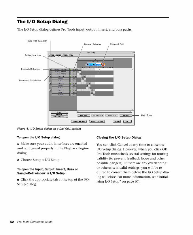
62
The I/O Setup DialogThe I/O Setup dialog defines Pro Tools input, output, insert, and buss paths.
Pro Tools Reference Guide
Figure 4. I/O Setup dialog on a Digi 001 system
Channel GridPath Type selector
Expand/Collapse
Active/Inactive
Path Tools
Main and Sub-Paths
Format Selector
To open the I/O Setup dialog:
1 Make sure your audio interfaces are enabled and configured properly in the Playback Engine dialog.
2 Choose Setup > I/O Setup.
To open the Input, Output, Insert, Buss or SampleCell window in I/O Setup:
■ Click the appropriate tab at the top of the I/O Setup dialog.
Closing the I/O Setup Dialog
You can click Cancel at any time to close the I/O Setup dialog. However, when you click OK Pro Tools must check several settings for routing validity (to prevent feedback loops and other possible dangers). If there are any overlapping or otherwise invalid settings, you will be re-quired to correct them before the I/O Setup dia-log will close. For more information, see “Initial-izing I/O Setup” on page 67.
Controls in I/O Setup
This section provides an overview of the con-trols available in the I/O Setup dialog.
Path Type Tabs Selects the type of I/O to config-ure. Choices are Inputs, Outputs, Busses, Inserts or SampleCell. (SampleCell paths are available on TDM-equipped systems only.)
Path Selection Column (Shows paths that are currently selected.
Expand/Collapse Paths Shows/hides the Sub-paths associated with a Main Path.
Path Name Column Shows the user-defined names of each defined path.
Active/Inactive Column Shows the active/inac-tive status of each path.
Path Format Popup Shows the selected type/for-mat (mono, stereo, 5.1, etc.) of each defined path.
Channel Grid Maps paths to specific I/O units and channels.
Path Tools The New Path, New Sub-Path, Delete Path, and Default buttons are used to customize the I/O Setup configuration.
Show Original Setup An additional button (Show Original Setup) is displayed in the I/O Setup di-alog in certain session transfer situation. For de-tails on this feature, see “Show Original and Show Current Setup” on page 70.
Default Options These four popup menus select default Metering Path, Audition Path (Regions List previewing), Output Path (for new tracks), and default channel order. See “Default Output, Metering, Audition, and Path Order” on page 72.
Creating and Editing Paths The I/O Setup dialog lets you create and custom-ize signal path definitions.
Paths can be:
• Renamed, for easier identification after changing or renaming audio interfaces
• Remapped, to or from different sources or des-tinations
• De-activated (or re-activated) to manage un-available or unnecessary I/O resources
• Deleted
In addition, you can import and export your I/O Setup configurations as I/O Settings files, as well as set numerous default path parameters
The following table lists the available path at-tributes for each path type.
Path Options by Type
Path Type Path Attributes
Input Names, formats, and source channel (analog or digital audio interface, or CPU input)
Output Names, formats, and destination (audio interface output channel or internal send bus)
Insert Names, formats and destination (audio interface channels)
Buss Names and formats
SampleCell Input names
Chapter 7: I/O Setup 63
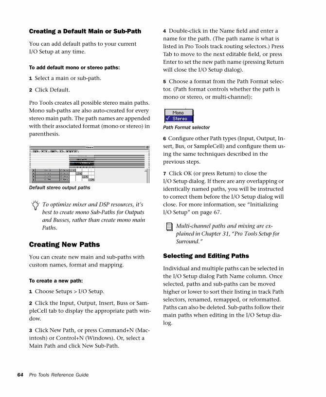
64
Creating a Default Main or Sub-Path
You can add default paths to your current I/O Setup at any time.
To add default mono or stereo paths:
1 Select a main or sub-path.
2 Click Default.
Pro Tools creates all possible stereo main paths. Mono sub-paths are also auto-created for every stereo main path. The path names are appended with their associated format (mono or stereo) in parenthesis.
Creating New Paths
You can create new main and sub-paths with custom names, format and mapping.
To create a new path:
1 Choose Setups > I/O Setup.
2 Click the Input, Output, Insert, Buss or Sam-pleCell tab to display the appropriate path win-dow.
3 Click New Path, or press Command+N (Mac-intosh) or Control+N (Windows). Or, select a Main Path and click New Sub-Path.
Default stereo output paths
To optimize mixer and DSP resources, it’s best to create mono Sub-Paths for Outputs and Busses, rather than create mono main Paths.
Pro Tools Reference Guide
4 Double-click in the Name field and enter a name for the path. (The path name is what is listed in Pro Tools track routing selectors.) Press Tab to move to the next editable field, or press Enter to set the new path name (pressing Return will close the I/O Setup dialog).
5 Choose a format from the Path Format selec-tor. (Path format controls whether the path is mono or stereo, or multi-channel):
6 Configure other Path types (Input, Output, In-sert, Bus, or SampleCell) and configure them us-ing the same techniques described in the previous steps.
7 Click OK (or press Return) to close the I/O Setup dialog. If there are any overlapping or identically named paths, you will be instructed to correct them before the I/O Setup dialog will close. For more information, see “Initializing I/O Setup” on page 67.
Selecting and Editing Paths
Individual and multiple paths can be selected in the I/O Setup dialog Path Name column. Once selected, paths and sub-paths can be moved higher or lower to sort their listing in track Path selectors, renamed, remapped, or reformatted. Paths can also be deleted. Sub-paths follow their main paths when editing in the I/O Setup dia-log.
Path Format selector
Multi-channel paths and mixing are ex-plained in Chapter 31, “Pro Tools Setup for Surround.”
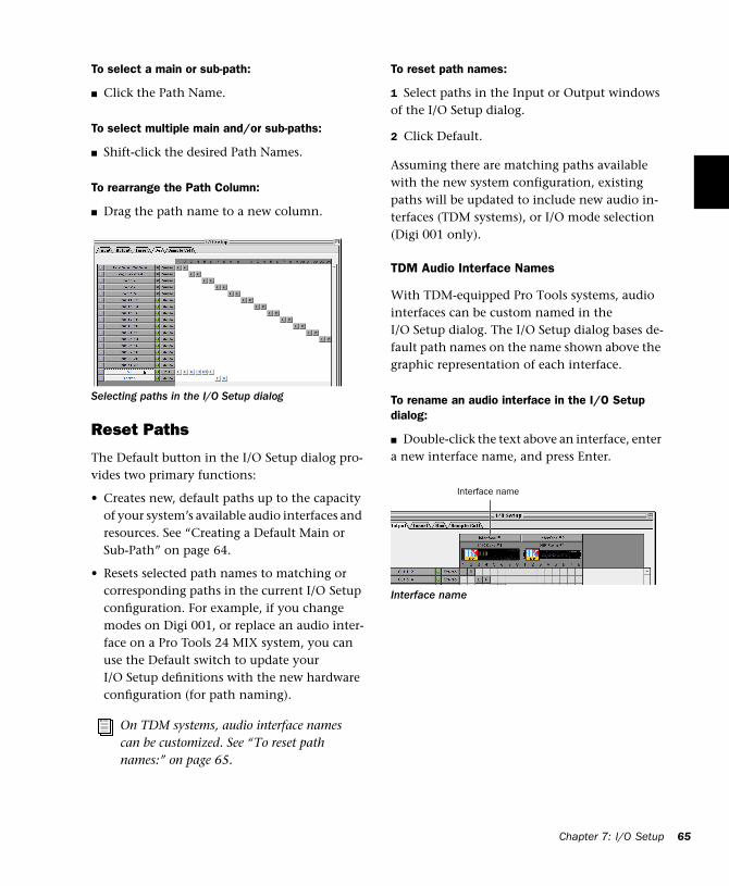
To select a main or sub-path:
■ Click the Path Name.
To select multiple main and/or sub-paths:
■ Shift-click the desired Path Names.
To rearrange the Path Column:
■ Drag the path name to a new column.
Reset Paths
The Default button in the I/O Setup dialog pro-vides two primary functions:
• Creates new, default paths up to the capacity of your system’s available audio interfaces and resources. See “Creating a Default Main or Sub-Path” on page 64.
• Resets selected path names to matching or corresponding paths in the current I/O Setup configuration. For example, if you change modes on Digi 001, or replace an audio inter-face on a Pro Tools 24 MIX system, you can use the Default switch to update your I/O Setup definitions with the new hardware configuration (for path naming).
Selecting paths in the I/O Setup dialog
On TDM systems, audio interface names can be customized. See “To reset path names:” on page 65.
To reset path names:
1 Select paths in the Input or Output windows of the I/O Setup dialog.
2 Click Default.
Assuming there are matching paths available with the new system configuration, existing paths will be updated to include new audio in-terfaces (TDM systems), or I/O mode selection (Digi 001 only).
TDM Audio Interface Names
With TDM-equipped Pro Tools systems, audio interfaces can be custom named in the I/O Setup dialog. The I/O Setup dialog bases de-fault path names on the name shown above the graphic representation of each interface.
To rename an audio interface in the I/O Setup dialog:
■ Double-click the text above an interface, enter a new interface name, and press Enter.
Interface name
Interface name
Chapter 7: I/O Setup 65
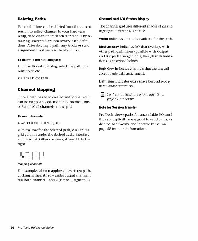
66
Deleting Paths
Path definitions can be deleted from the current session to reflect changes to your hardware setup, or to clean up track selector menus by re-moving unwanted or unnecessary path defini-tions. After deleting a path, any tracks or send assignments to it are reset to No Output.
To delete a main or sub-path:
1 In the I/O Setup dialog, select the path you want to delete.
2 Click Delete Path.
Channel Mapping
Once a path has been created and formatted, it can be mapped to specific audio interface, bus, or SampleCell channels in the grid.
To map channels:
1 Select a main or sub-path.
2 In the row for the selected path, click in the grid column under the desired audio interface and channel. Other channels, if any, fill to the right.
For example, when mapping a new stereo path, clicking in the path row under output channel 1 fills both channel 1 and 2 (left to 1, right to 2).
Mapping channels
Pro Tools Reference Guide
Channel and I/O Status Display
The channel grid uses different shades of gray to highlight different I/O status:
White Indicates channels available for the path.
Medium Gray Indicates I/O that overlaps with other path definitions (possible with Output and Bus path arrangements, though with limita-tions as described below).
Dark Gray Indicates channels that are unavail-able for sub-path assignment.
Light Gray Indicates extra space beyond recog-nized audio interfaces.
Note for Session Transfer
Pro Tools shows paths for unavailable I/O until they are explicitly re-assigned to valid paths, or deleted. See “Active and Inactive Paths” on page 68 for more information.
See “Valid Paths and Requirements” on page 67 for details.
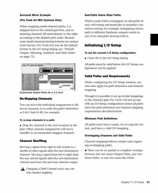
Surround Mixer Example
(Pro Tools 24 MIX Systems Only)
When mapping multi-channel paths, L is mapped first to the clicked grid box, and re-maining channels fill immediately to the right according to the default path order. Because some multi-channel mixing formats use unique track layouts, Pro Tools lets you set the default format in the I/O Setup dialog (see “Default Output, Metering, Audition, and Path Order” on page 72).
Re-Mapping Channels
You can move the individual assignments to dif-ferent channels, to re-order the path’s definition as L-R-C-Sub-LS-RS, for example.
To re-map channels in a path:
■ Drag the channel to the new location in the grid. Other channel assignments will move (shuffle) to accommodate dragged channels.
Channel Shuffling
Moving a signal from right to left results in a shuffle of other signals after the new destination channel. Moving a signal from left to right shuf-fles any and all signals after the new destination channel and leave the previous channel empty.
Customized Output Paths for a 5.1 mix?
Changing a Path’s format erases any cur-rent channel mapping.
Sub-Paths follow Main Paths
When a main Path is remapped, its sub-paths (if any) will remap automatically to maintain con-sistent routing. For example, remapping a stereo path to different hardware outputs results in any of its sub-paths moving with it.
Initializing I/O Setup
To set the current I/O Setup configuration:
■ Click OK in the I/O Setup dialog.
All paths must be valid before the I/O Setup con-figuration can be applied.
Valid Paths and Requirements
While configuring the I/O Setup window, cer-tain rules apply for path definition and channel mapping.
Though it is possible to set up invalid mappings in the channel grid, Pro Tools will not accept (OK) an I/O Setup configuration unless all paths meet the path definition and channel mapping requirements described below.
Minimum Path Definitions
All paths must have a name, be of a specific for-mat, and have a valid I/O mapping.
Overlapping Channels and Valid Paths
Channel mapping follows certain rules regard-ing overlapping paths.
◆ There can be no partial or complete overlaps between any two main Output Paths, any two Insert Paths, or any two main Bus Paths.
Chapter 7: I/O Setup 67
68
◆ A newly created Output or Bus Path must ei-ther be completely independent (mapped to any other available I/O interface/channels) of other paths, or it must be a sub-path completely contained within a larger path (for example, an LCR sub-path within a larger 5.1 path).
◆ Output and Insert Paths can overlap in I/O Setup, but only one or the other can be used at any given time in a session. (Inputs and Sample-Cell paths, however, can be routed to multiple tracks.)
Active and Inactive Paths
Pro Tools paths can be Active (on) or Inactive (off, or unavailable). You can manually switch paths between Active or Inactive on a per track or session-wide basis. In addition, Pro Tools sets paths to Inactive automatically when I/O is un-available.
Track Path Assignments Track input, output and buss path assignments can be switched to Inactive using the appropriate selector on the desired track. Doing so leaves track playlists in-tact, while disconnecting that particular track from the output or buss path. Use this to remove a track from a signal path.
Session-Wide Paths can be globally activated or de-activated in the I/O Setup window. Use this to turn off a signal path on any and all tracks currently assigned to it. Pro Tools also sets un-available paths to inactive. Paths can be unavail-able when hardware or other system resources are unavailable, such as when opening a session last saved on a different system.
Pro Tools Reference Guide
Active and Inactive Path Assignments
To toggle a track path assignment to Active or Inactive:
■ In the Mix (or Edit) window, Command-Con-trol-click (Macintosh) or Control-Start-click (Windows) the track’s Input, Output, Insert, or Send Selector.
Inactive track path assignments are indicated with an asterisk (*) in its track selector menu. (Paths set to globally inactive in the I/O Setup window are listed in italics.)
Toggling All or All Selected
The Option/Option + Shift modifiers apply the path toggle to all or all selected tracks, respec-tively. However, Pro Tools will only apply the change to identical path assignments, if any, in the current track or tracks. In other words, tog-gling multiple tracks only affects tracks that have the same path assignment as the one you are explicitly toggling.
Toggling Multiple Paths
If a track has only one main output assignment, you can Command-Control-click (Macintosh) or Control-start-click (Windows) the track’s Output Selector to toggle the main output to in-active. When there are multiple assignments, the track selector will be displayed for you to specify the input, output, insert, or bus path.
If a Send (A - E) has multiple output assignments and one of those is toggled, then all of the out-put assignments for that Send (A - E) will be tog-gled.
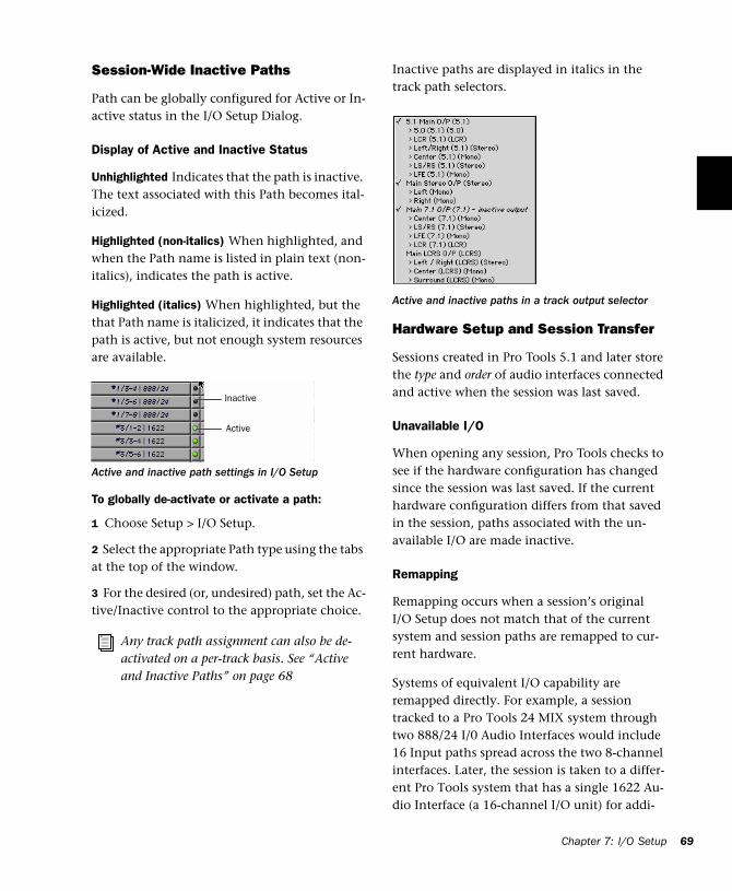
Session-Wide Inactive Paths
Path can be globally configured for Active or In-active status in the I/O Setup Dialog.
Display of Active and Inactive Status
Unhighlighted Indicates that the path is inactive. The text associated with this Path becomes ital-icized.
Highlighted (non-italics) When highlighted, and when the Path name is listed in plain text (non-italics), indicates the path is active.
Highlighted (italics) When highlighted, but the that Path name is italicized, it indicates that the path is active, but not enough system resources are available.
To globally de-activate or activate a path:
1 Choose Setup > I/O Setup.
2 Select the appropriate Path type using the tabs at the top of the window.
3 For the desired (or, undesired) path, set the Ac-tive/Inactive control to the appropriate choice.
Active and inactive path settings in I/O Setup
Any track path assignment can also be de-activated on a per-track basis. See “Active and Inactive Paths” on page 68
Inactive
Active
Inactive paths are displayed in italics in the track path selectors.
Hardware Setup and Session Transfer
Sessions created in Pro Tools 5.1 and later store the type and order of audio interfaces connected and active when the session was last saved.
Unavailable I/O
When opening any session, Pro Tools checks to see if the hardware configuration has changed since the session was last saved. If the current hardware configuration differs from that saved in the session, paths associated with the un-available I/O are made inactive.
Remapping
Remapping occurs when a session’s original I/O Setup does not match that of the current system and session paths are remapped to cur-rent hardware.
Systems of equivalent I/O capability are remapped directly. For example, a session tracked to a Pro Tools 24 MIX system through two 888/24 I/0 Audio Interfaces would include 16 Input paths spread across the two 8-channel interfaces. Later, the session is taken to a differ-ent Pro Tools system that has a single 1622 Au-dio Interface (a 16-channel I/O unit) for addi-
Active and inactive paths in a track output selector
Chapter 7: I/O Setup 69
70
tional editing. When the session is first opened on the 1622-equipped system, Pro Tools maps those input paths to the most appropriate in-puts of the 1622, left-to-right. (Mapping will de-pend on mono and stereo track format and ar-rangement in the Mix and Edit windows.)
When hardware is unavailable to a session being opened, assignments can either be replaced us-ing the remap option, or opened as Inactive. Any tracks left assigned to an unavailable path will not be audible. This can beneficial, how-ever, when you want to re-assign tracks into your system’s mix one at a time.
Show Original and Show Current Setup
When a session is opened that contains path definitions for unavailable I/O modules, the I/O Setup dialog lists those paths in italics.
The Show Original Setup button displays the au-dio interfaces used in the original session. This temporary display lets you check the original I/O configuration for reference while configur-ing the session for your system.
Once a session has been opened with unavail-able I/O retained, you can then re-assign tracks to available I/O paths.
See “Active and Inactive Paths” on page 68 for more information.
To redefine the paths, see “Creating and Editing Paths” on page 63.
Pro Tools Reference Guide
I/O Settings FilesI/O Settings can be managed when transferring sessions, and when developing I/O Setup con-figurations over the course of multiple sessions and projects.
Defaults, Settings Files, and Last Used Settings for New Sessions
When creating new sessions, you can select the session’s I/O Setup configuration from among numerous options:
Default I/O Setups The Pro Tools Installer pro-vides factory presets for stereo and surround I/O Setups (surround mixing is only supported on Pro Tools 24 MIX systems). See “Factory I/O Set-tings Files” on page 71 for more information.
Custom Presets You can store and recall custom presets using the export and import features of the I/O Setup dialog.
Last Used The most recent (or, last used) I/O Setup configuration is saved as a Last Used settings file. See “Last Used” on page 71 for more information.
Default I/O Settings at First Launch
The first time you create a session, you can choose default Stereo Mix or Surround Mix set-tings, depending on your system and installa-tion choices. See “Factory I/O Settings Files” on page 71.
Importing and Exporting I/O Settings Files
You can export and import I/O Setup configura-tions as I/O Settings files. This lets you save set-tings for different projects, import settings for quick reconfiguration, and manage Path defini-tions and signal routing setups.
To export and save an I/O Setup configuration:
1 Click the Export Settings button.
2 Name and save the settings file.
Importing I/O Settings
I/O Settings can be imported into the current session. When doing so, you can choose to de-lete your system’s existing (last used) path defi-nitions and replace them with settings being im-ported. Or, you can retain both your current and imported settings. Imported paths are added to the current configuration.
To import an I/O Settings file:
1 Click Import Settings in the I/O Setup dialog.
2 Select the desired settings file in the dialog.
3 You will be asked whether you want to delete, or retain, existing paths:
Delete Existing Paths Pro Tools remaps the orig-inal session path definitions to your current hardware setup of audio interfaces, left to right. The session will no longer have any references to or record of the original I/O assignments. When old path definitions are deleted, associ-ated assignment and automation data is also de-leted.
To start sessions with a blank or empty I/O Setup dialog, you must create and ex-port a user setting file in which all defini-tions have been deleted.
Do Not Delete Existing Paths Pro Tools adds ses-sion paths to the current system’s I/O Setup If you cancel the remap option, the original I/O assignments remain in the session. Unavailable I/O results in paths opening as Inactive. In the session, you can then re-assign tracks to avail-able paths as needed, based on their original (and inactive) I/O Setup and hardware configu-ration. See “Active and Inactive Paths” on page 68 for more information on utilizing inac-tive paths.
Last Used
If any changes are made to the I/O Setup dialog during a session, these changes are saved to the Last Used settings file when the I/O Setup dialog is closed.
Changes to I/O Setup are only saved in the cur-rent session, when the session is saved. User Pre-sets files will not contain recent changes unless you explicitly export an updated settings file.
The Last Used settings are available as a choice (or default) when creating or opening sessions, in addition to the factory presets described be-low.
Factory I/O Settings Files
Pro Tools provides I/O Settings files for Stereo and Surround mixing. These files provide ge-neric Main and Sub-Path definitions for either mixing format.
Stereo Mix Settings File
The Stereo Mix preset consists of all possible ste-reo and mono paths for your session.
Using the “Stereo Mix” preset has the same effect as hitting the Default Button for every individual tab in I/O Settings. See “Creating and Editing Paths” on page 63 for details.
Chapter 7: I/O Setup 71
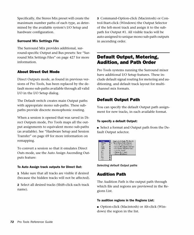
72
Specifically, the Stereo Mix preset will create the maximum number paths of each type, as deter-mined by the available system’s I/O Setup and hardware configuration.
Surround Mix Settings File
The Surround Mix provides additional, sur-round-specific Output and Bus presets: See “Sur-round Mix Settings Files” on page 427 for more information.
About Direct Out Mode
Direct Outputs mode, as found in previous ver-sions of Pro Tools, has been replaced by the de-fault mono sub-paths available through all valid I/O in the I/O Setup dialog.
The Default switch creates main Output paths with appropriate mono sub-paths. These sub-paths provide discrete monophonic routing.
When a session is opened that was saved in Di-rect Outputs mode, Pro Tools maps all the out-put assignments to equivalent mono sub-paths (as available). See “Hardware Setup and Session Transfer” on page 69 for more information on remapping.
To convert a session so that it emulates Direct Outs mode, use the Auto Assign Ascending Out-puts feature:
To Auto Assign track outputs for Direct Out:
1 Make sure that all tracks are visible if desired (because the hidden tracks will not be affected).
2 Select all desired tracks (Shift-click each track name).
Pro Tools Reference Guide
3 Command-Option-click (Macintosh) or Con-trol-Start-click (Windows) the Output Selector of the left-most track and assign it to the sub-path for Output #1. All visible tracks will be auto-assigned to unique mono sub-path outputs in ascending order.
Default Output, Metering, Audition, and Path OrderPro Tools systems running the Surround mixer have additional I/O Setup features. These in-clude default signal routing for metering and au-ditioning, and default track layout for multi-channel mix formats.
Default Output Path
You can specify the default Output path assign-ment for new tracks, in each available format.
To specify a default Output:
■ Select a format and Output path from the De-fault Output selector.
Audition Path
The Audition Path is the output path through which file and regions are previewed in the Re-gions List.
To audition regions in the Regions List:
■ Option-click (Macintosh) or Alt-click (Win-dows) the region in the list.
Selecting default Output paths
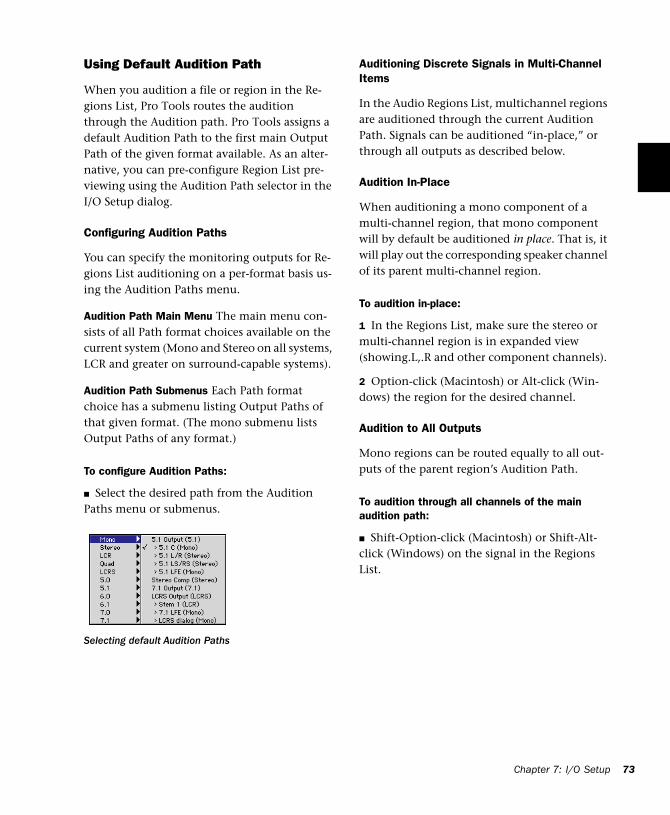
Using Default Audition Path
When you audition a file or region in the Re-gions List, Pro Tools routes the audition through the Audition path. Pro Tools assigns a default Audition Path to the first main Output Path of the given format available. As an alter-native, you can pre-configure Region List pre-viewing using the Audition Path selector in the I/O Setup dialog.
Configuring Audition Paths
You can specify the monitoring outputs for Re-gions List auditioning on a per-format basis us-ing the Audition Paths menu.
Audition Path Main Menu The main menu con-sists of all Path format choices available on the current system (Mono and Stereo on all systems, LCR and greater on surround-capable systems).
Audition Path Submenus Each Path format choice has a submenu listing Output Paths of that given format. (The mono submenu lists Output Paths of any format.)
To configure Audition Paths:
■ Select the desired path from the Audition Paths menu or submenus.
Selecting default Audition Paths
Auditioning Discrete Signals in Multi-Channel Items
In the Audio Regions List, multichannel regions are auditioned through the current Audition Path. Signals can be auditioned “in-place,” or through all outputs as described below.
Audition In-Place
When auditioning a mono component of a multi-channel region, that mono component will by default be auditioned in place. That is, it will play out the corresponding speaker channel of its parent multi-channel region.
To audition in-place:
1 In the Regions List, make sure the stereo or multi-channel region is in expanded view (showing.L,.R and other component channels).
2 Option-click (Macintosh) or Alt-click (Win-dows) the region for the desired channel.
Audition to All Outputs
Mono regions can be routed equally to all out-puts of the parent region’s Audition Path.
To audition through all channels of the main audition path:
■ Shift-Option-click (Macintosh) or Shift-Alt-click (Windows) on the signal in the Regions List.
Chapter 7: I/O Setup 73
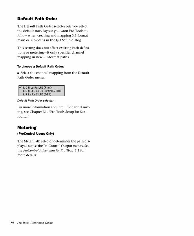
74
Default Path Order
The Default Path Order selector lets you select the default track layout you want Pro Tools to follow when creating and mapping 5.1-format main or sub-paths in the I/O Setup dialog.
This setting does not affect existing Path defini-tions or metering—it only specifies channel mapping in new 5.1-format paths.
To choose a Default Path Order:
■ Select the channel mapping from the Default Path Order menu.
For more information about multi-channel mix-ing, see Chapter 31, “Pro Tools Setup for Sur-round.”
Metering(ProControl Users Only)
The Meter Path selector determines the path dis-played across the ProControl Output meters. See the ProControl Addendum for Pro Tools 5.1 for more details.
Default Path Order selector
Pro Tools Reference Guide
Chapter 8: Tracks
This chapter covers basic track management tasks such as creating and deleting tracks, as-signing voices and output channels, and group-ing tracks.
Track TypesIn a Pro Tools session, you can have several dif-ferent types of tracks. These can include audio tracks, Auxiliary Input tracks, MIDI tracks, and Master Fader tracks. On a Macintosh system, a session can have a QuickTime, AVoption, or AVoption XL Movie track.
QuickTime Movie track features are de-scribed in Chapter 36, “Working with QuickTime Movies.”
Audio Tracks, Auxiliary Input Tracks, and Master Fader Tracks
Pro Tools provides mono, stereo, and multi-channel format audio tracks, Auxiliary Inputs, and Master Faders.
Audio Track
Audio tracks contain arrangements of recorded (or imported) audio files.Audio tracks can be mono, stereo, or multi-channel surround (Pro Tools 24 MIX systems only).
Auxiliary Input Track
Auxiliary Input tracks can be used as effects sends, destinations for alternate mix, as a bounce destination, and for many other audio routing tasks.
Master Fader Track
Master Fader tracks control the overall level of the audio tracks that are routed to the session’s main outputs.
MIDI Tracks
MIDI tracks store MIDI note, instrument, and controller data. There is no option for selecting the track format when you create a MIDI track, because audio does not pass through it.
Chapter 8: Tracks 75
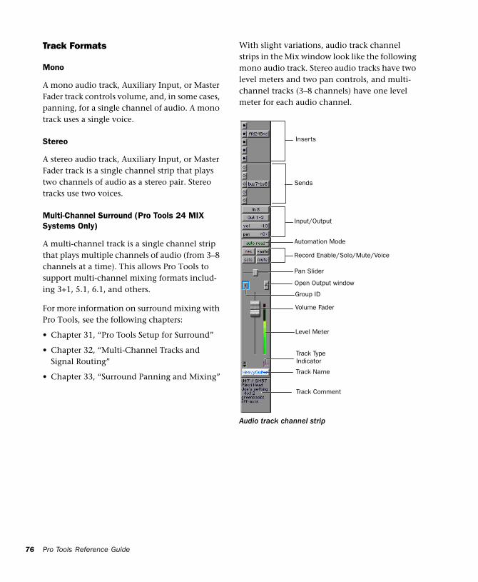
76
Track Formats
Mono
A mono audio track, Auxiliary Input, or Master Fader track controls volume, and, in some cases, panning, for a single channel of audio. A mono track uses a single voice.
Stereo
A stereo audio track, Auxiliary Input, or Master Fader track is a single channel strip that plays two channels of audio as a stereo pair. Stereo tracks use two voices.
Multi-Channel Surround (Pro Tools 24 MIX Systems Only)
A multi-channel track is a single channel strip that plays multiple channels of audio (from 3–8 channels at a time). This allows Pro Tools to support multi-channel mixing formats includ-ing 3+1, 5.1, 6.1, and others.
For more information on surround mixing with Pro Tools, see the following chapters:
• Chapter 31, “Pro Tools Setup for Surround”
• Chapter 32, “Multi-Channel Tracks and Signal Routing”
• Chapter 33, “Surround Panning and Mixing”
Pro Tools Reference Guide
With slight variations, audio track channel strips in the Mix window look like the following mono audio track. Stereo audio tracks have two level meters and two pan controls, and multi-channel tracks (3–8 channels) have one level meter for each audio channel.
Audio track channel strip
Inserts
Sends
Input/Output
Record Enable/Solo/Mute/Voice
Automation Mode
Track Name
Pan Slider
Level Meter
Volume Fader
Group ID
Open Output window
Track Comment
Track Type Indicator
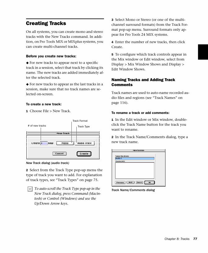
Creating TracksOn all systems, you can create mono and stereo tracks with the New Tracks command. In addi-tion, on Pro Tools MIX or MIXplus systems, you can create multi-channel tracks.
Before you create new tracks:
◆ For new tracks to appear next to a specific track in a session, select that track by clicking its name. The new tracks are added immediately af-ter the selected track.
◆ For new tracks to appear as the last tracks in a session, make sure that no track names are se-lected on-screen.
To create a new track:
1 Choose File > New Track.
2 Select from the Track Type pop-up menu the type of track you want to add. For explanation of track types, see “Track Types” on page 75.
New Track dialog (audio track)
To auto-scroll the Track Type pop-up in the New Track dialog, press Command (Macin-tosh) or Control (Windows) and use the Up/Down Arrow keys.
Track Format
Track Type# of new tracks
3 Select Mono or Stereo (or one of the multi-channel surround formats) from the Track For-mat pop-up menu. Surround formats only ap-pear for Pro Tools 24 MIX systems.
4 Enter the number of new tracks, then click Create.
5 To configure which track controls appear in the Mix window or Edit window, select from Display > Mix Window Shows and Display > Edit Window Shows.
Naming Tracks and Adding Track Comments
Track names are used to auto-name recorded au-dio files and regions (see “Track Names” on page 116).
To rename a track or add comments:
1 In the Edit window or Mix window, double-click the Track Name button for the track you want to rename.
2 In the Track Name/Comments dialog, type a new track name.
Track Name/Comments dialog
Chapter 8: Tracks 77
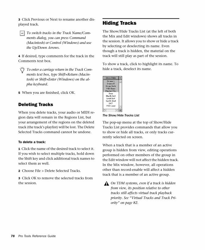
78
3 Click Previous or Next to rename another dis-played track.
4 If desired, type comments for the track in the Comments text box.
5 When you are finished, click OK.
Deleting Tracks
When you delete tracks, your audio or MIDI re-gion data will remain in the Regions List, but your arrangement of the regions on the deleted track (the track’s playlist) will be lost. The Delete Selected Tracks command cannot be undone.
To delete a track:
1 Click the name of the desired track to select it. If you wish to select multiple tracks, hold down the Shift key and click additional track names to select them as well.
2 Choose File > Delete Selected Tracks.
3 Click OK to remove the selected tracks from the session.
To switch tracks in the Track Name/Com-ments dialog, you can press Command (Macintosh) or Control (Windows) and use the Up/Down Arrows.
To enter a carriage return in the Track Com-ments text box, type Shift+Return (Macin-tosh) or Shift+Enter (Windows) on the al-pha keyboard.
Pro Tools Reference Guide
Hiding TracksThe Show/Hide Tracks List (at the left of both the Mix and Edit windows) shows all tracks in the session. It allows you to show or hide a track by selecting or deselecting its name. Even though a track is hidden, the material on the track will still play as part of the session.
To show a track, click to highlight its name. To hide a track, deselect its name.
The pop-up menu at the top of Show/Hide Tracks List provides commands that allow you to show or hide all tracks, or only tracks cur-rently selected on screen.
When a track that is a member of an active group is hidden from view, editing operations performed on other members of the group in the Edit window will not affect the hidden track. In the Mix window, however, all operations other than record-enable will affect a hidden track that is a member of an active group.
The Show/Hide Tracks List
On TDM systems, even if a track is hidden from view, its position relative to other tracks still affects virtual track playback priority. See “Virtual Tracks and Track Pri-ority” on page 82.
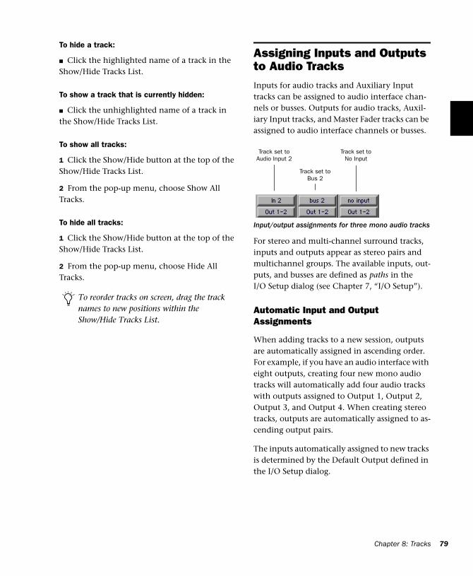
To hide a track:
■ Click the highlighted name of a track in the Show/Hide Tracks List.
To show a track that is currently hidden:
■ Click the unhighlighted name of a track in the Show/Hide Tracks List.
To show all tracks:
1 Click the Show/Hide button at the top of the Show/Hide Tracks List.
2 From the pop-up menu, choose Show All Tracks.
To hide all tracks:
1 Click the Show/Hide button at the top of the Show/Hide Tracks List.
2 From the pop-up menu, choose Hide All Tracks.
To reorder tracks on screen, drag the track names to new positions within the Show/Hide Tracks List.
Assigning Inputs and Outputs to Audio TracksInputs for audio tracks and Auxiliary Input tracks can be assigned to audio interface chan-nels or busses. Outputs for audio tracks, Auxil-iary Input tracks, and Master Fader tracks can be assigned to audio interface channels or busses.
For stereo and multi-channel surround tracks, inputs and outputs appear as stereo pairs and multichannel groups. The available inputs, out-puts, and busses are defined as paths in the I/O Setup dialog (see Chapter 7, “I/O Setup”).
Automatic Input and Output Assignments
When adding tracks to a new session, outputs are automatically assigned in ascending order. For example, if you have an audio interface with eight outputs, creating four new mono audio tracks will automatically add four audio tracks with outputs assigned to Output 1, Output 2, Output 3, and Output 4. When creating stereo tracks, outputs are automatically assigned to as-cending output pairs.
The inputs automatically assigned to new tracks is determined by the Default Output defined in the I/O Setup dialog.
Input/output assignments for three mono audio tracks
Track set to Audio Input 2
Track set to Bus 2
Track set to No Input
Chapter 8: Tracks 79
80
Assigning Audio Track Inputs
To assign an audio track input:
1 To display inputs and outputs in the Edit win-dow, select Display > Edit Window Show > I/O.
2 In the Mix or Edit window, click the track In-put Selector and choose from the available au-dio interface channels and busses. Stereo and multi-channel surround tracks have inputs available as pairs and multi-channel groups.
3 To remove an input assign, select No Input from the Input Selector.
Assigning Audio Track Outputs
To assign an audio track output:
1 To display inputs and outputs in the Edit win-dow, select Display > Edit Window Show > I/O.
2 In the Mix or Edit window, click the track Out-put Selector and choose from the available au-dio interface channels and busses. Stereo and multi-channel surround tracks have outputs available as pairs and multi-channel groups.
3 To remove an output assign, select No Output from the Input Selector. Playlists become dimmed for tracks with no output assignment.
Assigning an audio track, Auxiliary Input, or Master Fader to “No Output” will cause its automation data for pan and plug-in pa-rameters to be lost.
Pro Tools Reference Guide
Assigning Voices and Track Priority(TDM Systems Only)
Pro Tools 24 MIX systems provides up to 64 si-multaneous voices of audio playback. Pro Tools 24 systems provide up to 32 voices of audio playback.
While your Pro Tools hardware allows a fixed number of voices, Pro Tools software provides for up to 128 virtual tracks—tracks that can be re-corded or imported, arranged, and cued for playback, but cannot all be played back simulta-neously.
For these situations, Pro Tools assigns priorities for tracks that compete for the available voices. Pro Tools provides two ways of adjusting play-back priority to audio tracks.
Tracks do not use up voices when:
• Their Voice Selector is set to Off.
• They are made inactive.
• They do not have an output and send assign-ment.
In addition, you can temporarily free a track’s voice during playback by muting it (see “Mute Frees Assigned Voice” on page 84).
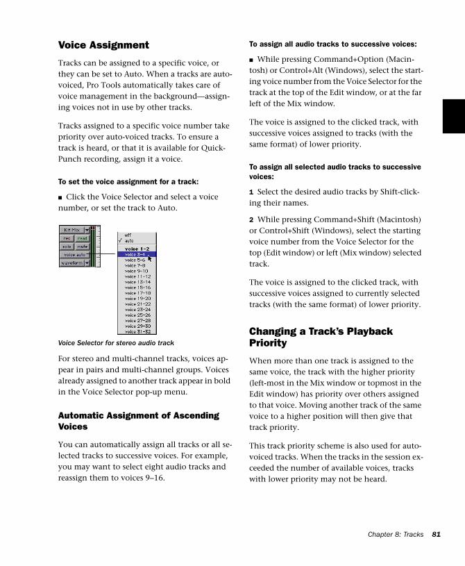
Voice Assignment
Tracks can be assigned to a specific voice, or they can be set to Auto. When a tracks are auto-voiced, Pro Tools automatically takes care of voice management in the background—assign-ing voices not in use by other tracks.
Tracks assigned to a specific voice number take priority over auto-voiced tracks. To ensure a track is heard, or that it is available for Quick-Punch recording, assign it a voice.
To set the voice assignment for a track:
■ Click the Voice Selector and select a voice number, or set the track to Auto.
For stereo and multi-channel tracks, voices ap-pear in pairs and multi-channel groups. Voices already assigned to another track appear in bold in the Voice Selector pop-up menu.
Automatic Assignment of Ascending Voices
You can automatically assign all tracks or all se-lected tracks to successive voices. For example, you may want to select eight audio tracks and reassign them to voices 9–16.
Voice Selector for stereo audio track
To assign all audio tracks to successive voices:
■ While pressing Command+Option (Macin-tosh) or Control+Alt (Windows), select the start-ing voice number from the Voice Selector for the track at the top of the Edit window, or at the far left of the Mix window.
The voice is assigned to the clicked track, with successive voices assigned to tracks (with the same format) of lower priority.
To assign all selected audio tracks to successive voices:
1 Select the desired audio tracks by Shift-click-ing their names.
2 While pressing Command+Shift (Macintosh) or Control+Shift (Windows), select the starting voice number from the Voice Selector for the top (Edit window) or left (Mix window) selected track.
The voice is assigned to the clicked track, with successive voices assigned to currently selected tracks (with the same format) of lower priority.
Changing a Track’s Playback Priority
When more than one track is assigned to the same voice, the track with the higher priority (left-most in the Mix window or topmost in the Edit window) has priority over others assigned to that voice. Moving another track of the same voice to a higher position will then give that track priority.
This track priority scheme is also used for auto-voiced tracks. When the tracks in the session ex-ceeded the number of available voices, tracks with lower priority may not be heard.
Chapter 8: Tracks 81
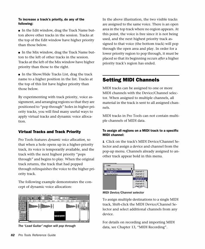
82
To increase a track’s priority, do any of the following:
■ In the Edit window, drag the Track Name but-ton above other tracks in the session. Tracks at the top of the Edit window have higher priority than those below.
■ In the Mix window, drag the Track Name but-ton to the left of other tracks in the session. Tracks at the left of the Mix window have higher priority than those to the right.
■ In the Show/Hide Tracks List, drag the track name to a higher position in the list. Tracks at the top of this list have higher priority than those below.
By experimenting with track priority, voice as-signment, and arranging regions so that they are positioned to “pop through” holes in higher pri-ority tracks, you will find many useful ways to apply virtual tracks and dynamic voice alloca-tion.
Virtual Tracks and Track Priority
Pro Tools features dynamic voice allocation, so that when a hole opens up in a higher-priority track, its voice is temporarily available, and the track with the next highest priority “pops through” and begins to play. When the original track returns, the track that had popped through relinquishes the voice to the higher pri-ority track.
The following example demonstrates the con-cept of dynamic voice allocation:
The “Lead Guitar” region will pop through
Pro Tools Reference Guide
In the above illustration, the two visible tracks are assigned to the same voice. There is an open area in the top track where no region appears. At this point, the voice is free since it is not being used, and the next highest priority track as-signed to that voice (the bottom track) will pop through the open area and play. In order for a lower priority region to pop through, it must be placed so that its beginning occurs after a higher priority track’s region has ended.
Setting MIDI ChannelsMIDI tracks can be assigned to one or more MIDI channels with the Device/Channel selec-tor. When assigned to multiple channels, all material in the track is sent to all assigned chan-nels.
MIDI tracks in Pro Tools can not contain multi-ple channels of MIDI data.
To assign all regions on a MIDI track to a specific MIDI channel:
1 Click on the track’s MIDI Device/Channel Se-lector and assign a device and channel from the pop-up menu. Channels already assigned to an-other track appear bold in this menu.
To assign multiple destinations to a single MIDI track, Shift-click the MIDI Device/Channel Se-lector and select additional channels from any device.
For details on recording and importing MIDI data, see Chapter 13, “MIDI Recording”.
MIDI Device/Channel selector
Soloing and Muting Tracks The Solo and Mute buttons can be engaged at any time during playback. The Solo and Mute buttons affect MIDI as well as audio tracks. It is possible to have more than one track soloed or muted at the same time in a session.
Grouping affects mute and solo behavior as well. Normally, muting or soloing a track that is a member of an active mix group will mute or solo all other tracks that are a member of that active mix group as well. However, by changing the Mute and Solo settings in the Pro Tools Pref-erences dialog, you can disable this behavior.
To disable group muting of tracks:
1 Choose Setups > Preferences, and click Auto-mation.
2 Deselect the Mutes Follow Mix Groups op-tion, and click OK.
With this option deselected, muting a track that is a member of an active group does not affect other members of the group.
To disable group soloing of tracks:
1 Choose Setups > Preferences, and click Auto-mation.
2 Deselect the Solos Follow Mix Groups option, and click OK.
With this option deselected, soloing a track that is a member of an active group does not affect other members of the group.
Solo Button
The solo button mutes other tracks so that the chosen track can be auditioned alone. Normally solos are “latched,” that is, pressing subsequent solo buttons adds them to the soloed mix of tracks. Pro Tools allows you to “unlatch” solos, so that pressing a solo button will mute all tracks except the track you have just soloed.
To solo a track:
1 Click the Solo button on the track. The button is highlighted and all other tracks are muted.
2 Click the Solo button again to turn off the solo function.
To unlatch solo buttons:
1 Choose Setups > Preferences and click Opera-tion.
2 Deselect the Latch Solo Buttons option and click Done. With this option disabled, pressing a Solo button mutes all tracks except the track you have just soloed.
Solo Safe Mode
Pro Tools also allows you to solo safe a track. This prevents the track from being muted even if you solo other tracks. This feature is useful for tracks such as Auxiliary Inputs that are being used as effects returns, allowing the effects track to remain in a mix even when other tracks are soloed. It is also useful to solo-safe MIDI tracks so that their playback is not affected when you solo audio tracks.
Chapter 8: Tracks 83
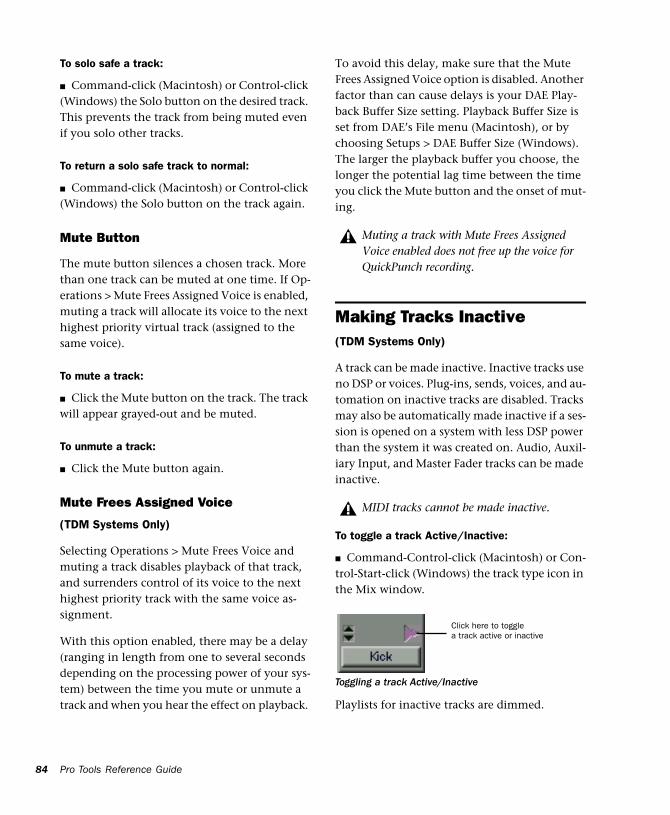
84
To solo safe a track:
■ Command-click (Macintosh) or Control-click (Windows) the Solo button on the desired track. This prevents the track from being muted even if you solo other tracks.
To return a solo safe track to normal:
■ Command-click (Macintosh) or Control-click (Windows) the Solo button on the track again.
Mute Button
The mute button silences a chosen track. More than one track can be muted at one time. If Op-erations > Mute Frees Assigned Voice is enabled, muting a track will allocate its voice to the next highest priority virtual track (assigned to the same voice).
To mute a track:
■ Click the Mute button on the track. The track will appear grayed-out and be muted.
To unmute a track:
■ Click the Mute button again.
Mute Frees Assigned Voice
(TDM Systems Only)
Selecting Operations > Mute Frees Voice and muting a track disables playback of that track, and surrenders control of its voice to the next highest priority track with the same voice as-signment.
With this option enabled, there may be a delay (ranging in length from one to several seconds depending on the processing power of your sys-tem) between the time you mute or unmute a track and when you hear the effect on playback.
Pro Tools Reference Guide
To avoid this delay, make sure that the Mute Frees Assigned Voice option is disabled. Another factor than can cause delays is your DAE Play-back Buffer Size setting. Playback Buffer Size is set from DAE’s File menu (Macintosh), or by choosing Setups > DAE Buffer Size (Windows). The larger the playback buffer you choose, the longer the potential lag time between the time you click the Mute button and the onset of mut-ing.
Making Tracks Inactive(TDM Systems Only)
A track can be made inactive. Inactive tracks use no DSP or voices. Plug-ins, sends, voices, and au-tomation on inactive tracks are disabled. Tracks may also be automatically made inactive if a ses-sion is opened on a system with less DSP power than the system it was created on. Audio, Auxil-iary Input, and Master Fader tracks can be made inactive.
To toggle a track Active/Inactive:
■ Command-Control-click (Macintosh) or Con-trol-Start-click (Windows) the track type icon in the Mix window.
Playlists for inactive tracks are dimmed.
Muting a track with Mute Frees Assigned Voice enabled does not free up the voice for QuickPunch recording.
MIDI tracks cannot be made inactive.
Toggling a track Active/Inactive
Click here to toggle a track active or inactive
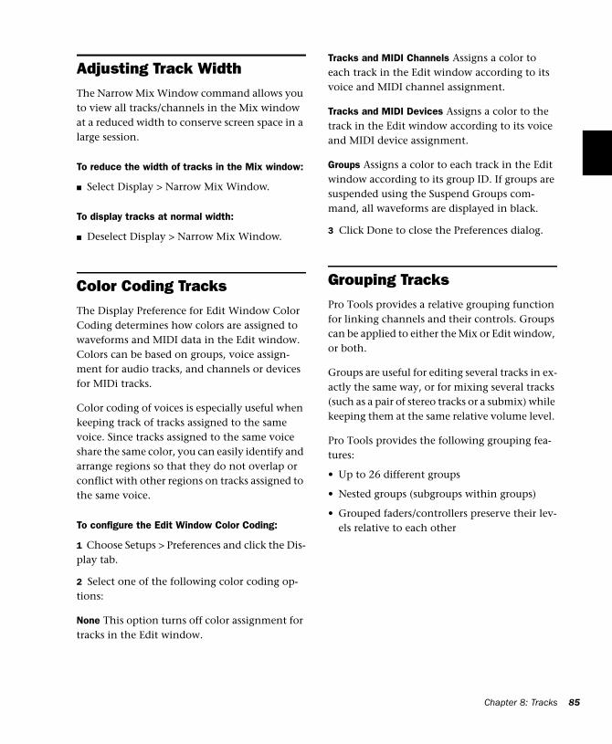
Adjusting Track WidthThe Narrow Mix Window command allows you to view all tracks/channels in the Mix window at a reduced width to conserve screen space in a large session.
To reduce the width of tracks in the Mix window:
■ Select Display > Narrow Mix Window.
To display tracks at normal width:
■ Deselect Display > Narrow Mix Window.
Color Coding TracksThe Display Preference for Edit Window Color Coding determines how colors are assigned to waveforms and MIDI data in the Edit window. Colors can be based on groups, voice assign-ment for audio tracks, and channels or devices for MIDi tracks.
Color coding of voices is especially useful when keeping track of tracks assigned to the same voice. Since tracks assigned to the same voice share the same color, you can easily identify and arrange regions so that they do not overlap or conflict with other regions on tracks assigned to the same voice.
To configure the Edit Window Color Coding:
1 Choose Setups > Preferences and click the Dis-play tab.
2 Select one of the following color coding op-tions:
None This option turns off color assignment for tracks in the Edit window.
Tracks and MIDI Channels Assigns a color to each track in the Edit window according to its voice and MIDI channel assignment.
Tracks and MIDI Devices Assigns a color to the track in the Edit window according to its voice and MIDI device assignment.
Groups Assigns a color to each track in the Edit window according to its group ID. If groups are suspended using the Suspend Groups com-mand, all waveforms are displayed in black.
3 Click Done to close the Preferences dialog.
Grouping TracksPro Tools provides a relative grouping function for linking channels and their controls. Groups can be applied to either the Mix or Edit window, or both.
Groups are useful for editing several tracks in ex-actly the same way, or for mixing several tracks (such as a pair of stereo tracks or a submix) while keeping them at the same relative volume level.
Pro Tools provides the following grouping fea-tures:
• Up to 26 different groups
• Nested groups (subgroups within groups)
• Grouped faders/controllers preserve their lev-els relative to each other
Chapter 8: Tracks 85
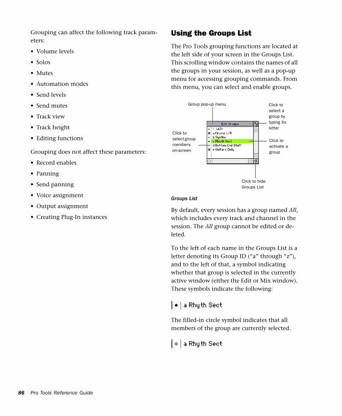
86
Grouping can affect the following track param-eters:
• Volume levels
• Solos
• Mutes
• Automation modes
• Send levels
• Send mutes
• Track view
• Track height
• Editing functions
Grouping does not affect these parameters:
• Record enables
• Panning
• Send panning
• Voice assignment
• Output assignment
• Creating Plug-In instances
Pro Tools Reference Guide
Using the Groups List
The Pro Tools grouping functions are located at the left side of your screen in the Groups List. This scrolling window contains the names of all the groups in your session, as well as a pop-up menu for accessing grouping commands. From this menu, you can select and enable groups.
By default, every session has a group named All, which includes every track and channel in the session. The All group cannot be edited or de-leted.
To the left of each name in the Groups List is a letter denoting its Group ID (“a” through “z”), and to the left of that, a symbol indicating whether that group is selected in the currently active window (either the Edit or Mix window). These symbols indicate the following:
The filled-in circle symbol indicates that all members of the group are currently selected.
Groups List
Group pop-up menu Click to select a group by typing its letter
Click to activate a group
Click to select group members on-screen
Click to hide Groups List
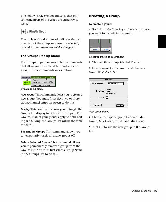
The hollow circle symbol indicates that only some members of the group are currently se-lected.
The circle with a dot symbol indicates that all members of the group are currently selected, plus additional members outside the group.
The Groups Pop-up Menu
The Groups pop-up menu contains commands that allow you to create, delete and suspend groups. These commands are as follows:
New Group This command allows you to create a new group. You must first select two or more tracks/channel strips on screen to do this.
Display This command allows you to toggle the Groups List display to either Mix Groups or Edit Groups. If all of your groups apply to both Edit-ing and Mixing, the Groups List will be the same for both.
Suspend All Groups This command allows you to temporarily toggle all active groups off.
Delete Selected Groups This command allows you to permanently remove a group from the Groups List. You must first select a Group Name in the Groups List to do this.
Group pop-up menu
Creating a Group
To create a group:
1 Hold down the Shift key and select the tracks you want to include in the group.
2 Choose File > Group Selected Tracks.
3 Enter a name for the group and choose a Group ID (“a” - “z”).
4 Choose the type of group to create: Edit Group, Mix Group, or Edit and Mix Group.
5 Click OK to add the new group to the Groups List.
Selecting tracks to be grouped
New Group dialog
Chapter 8: Tracks 87
88
Changing the Members of a Group
You can add or remove members from a group at any time.
To change the members of a group:
1 Hold down the Shift key and select the tracks to include in the group.
2 Choose New Group from the Group pop-up menu.
3 In the dialog that appears, select the Group ID that you want to update.
4 Click OK. The new group definition over-writes the original definition.
Renaming a Group
You can rename a group at any time.
To rename a group:
1 In the Groups List, double-click to the left of the group’s name (in the area with the circular symbols).
2 In the dialog that appears, enter a new name for the group. (If you wish to change the group’s type, you can also do so here.)
3 Click OK. The group is renamed in the Groups List.
Deleting a Group
You can delete a group at any time.
To delete a group:
1 In the Groups List, select the name of the group (or groups) you wish to delete.
2 Click the Group pop-up menu and choose De-lete Selected Groups. You cannot undo this ac-tion.
Pro Tools Reference Guide
Linking Mix and Edit Groupings
The “Link Mix and Edit Group Enables” option links group enabling between the Mix and Edit windows.
Pro Tools allows you to create groups that are both Mix and Edit groups. but in some cases you may prefer not to link enabling of Mix and Edit groups. For example, when you are using the Mix window for mixing, you may prefer to work with large, nested groups. However, in the Edit window, you may want to perform editing tasks within a smaller group. You could disable the Link Mix and Edit Group Enables preference. This would allow you to work with different groups in the two windows.
To unlink mix and edit groups:
1 Choose Setups > Preferences and click Opera-tion.
2 Deselect the “Link Mix and Edit Group En-ables” option and click Done.
Enabling Groups
Editing operations are not applied to members of a group that are hidden with the Show/Hide Tracks List. Mix operations (with the exception of Record-enable) are applied to hidden tracks.
Pro Tools allows you to create separate groups for editing and mixing. You set this option when you use the New Group command. Groups that apply to both editing and mixing can be decoupled.
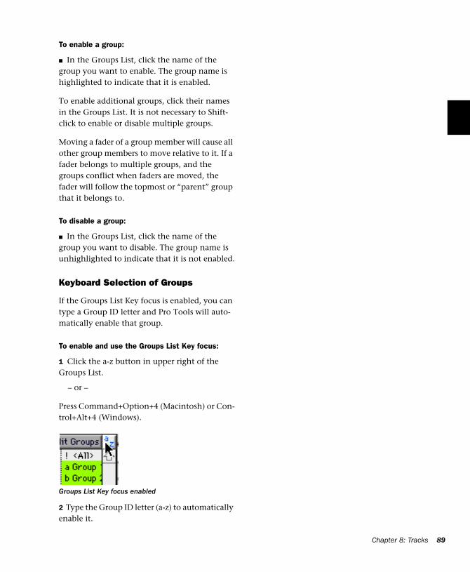
To enable a group:
■ In the Groups List, click the name of the group you want to enable. The group name is highlighted to indicate that it is enabled.
To enable additional groups, click their names in the Groups List. It is not necessary to Shift-click to enable or disable multiple groups.
Moving a fader of a group member will cause all other group members to move relative to it. If a fader belongs to multiple groups, and the groups conflict when faders are moved, the fader will follow the topmost or “parent” group that it belongs to.
To disable a group:
■ In the Groups List, click the name of the group you want to disable. The group name is unhighlighted to indicate that it is not enabled.
Keyboard Selection of Groups
If the Groups List Key focus is enabled, you can type a Group ID letter and Pro Tools will auto-matically enable that group.
To enable and use the Groups List Key focus:
1 Click the a-z button in upper right of the Groups List.
– or –
Press Command+Option+4 (Macintosh) or Con-trol+Alt+4 (Windows).
2 Type the Group ID letter (a-z) to automatically enable it.
Groups List Key focus enabled
Chapter 8: Tracks 89

90
Pro Tools Reference Guide
Chapter 9: Importing and Exporting Audio and MIDI
Importing AudioIn Pro Tools you can import previously recorded audio files and regions from other sessions or other applications. You can also import tracks from other Pro Tools sessions (see “Importing Tracks from Other Sessions” on page 94), and convert the audio while importing.
Audio files and regions can be imported to new tracks, or they can be imported into the Audio Regions List, where they can be dragged to exist-ing tracks.
Audio files in the following formats can be im-ported:
• AIFF
• WAV
• SDII
• SDI
• MP3
• Sound Resource (AIFL—Macintosh only)
• WMA (Windows Media—Windows only)
Supported files and regions can be auditioned before importing.
If region definitions are present in an audio file, you can convert and import selected regions without importing the entire parent audio file.
When importing into a session, choose File > Import Audio to Track to place the audio into a new track. To import into the Audio Re-gions List, choose Convert & Import Audio from the Audio Regions pop-up menu. Both com-mands open the same Import Audio dialog (see Figure 5 on page 93).
Files that don’t match the session’s supported files types, must be converted when importing. If you import an audio file with a sample rate that doesn’t match the current session’s sample rate, and you do not convert it, the file will not play back at the original pitch.
Chapter 9: Importing and Exporting Audio and MIDI 91
92
Copying, Adding, and Converting Audio
Depending on the properties of the audio files you are importing, you can add, copy, or con-vert the files.
Add
Audio files that are of the same bit depth and file type can be added directly to a session. Use this option when you don’t want to use extra hard drive space for audio files that are already of the same bit depth and sample rate as your session. Note that added files remain in their original folder locations.
Pro Tools allows audio files that are not in the native session type to be added to a session. Macintosh sessions allow SDII, AIFF, or WAV files to be added to any session, and Windows sessions allow AIFF or WAV files to be added to any session. However, sessions with mixed file types will have reduced performance.
Audio files that are of a different bit depth must be converted.
Copy
If a file can be added to your session, you will also be given the option to copy it. This option creates a copy of the audio file and places it in a folder you choose.
Pro Tools allows you to add files to a ses-sion that are at a different sample rate than your session (48 kHz or 44.1 kHz). In the comments field of the Import Audio dialog, a warning is posted that these files will play back at the wrong speed if they are not con-verted.
Pro Tools Reference Guide
Use Copy when the file you are importing is of the correct bit depth and file type, but it is at the wrong sample rate, and you want it to play back correctly. You can also use Copy to move audio from an unsupported or removable drive to an audio drive, or to consolidate audio files for a session to a specific location.
Convert
Audio files that are not of the same bit depth or audio files that are of an incompatible file type (SDII files in Windows or on the Macintosh in a Mac/PC compatible session) must be converted to be used with a session. When audio files are converted, a new file with the correct bit depth, file type, and sample rate is created and placed in a folder you choose.
The quality of sample rate conversion used by Pro Tools is determined by the Preference for Conversion Quality. For details, see “Conver-sion Quality” on page 99.
Importing Stereo Files
When using the Import Audio to Tracks com-mand, stereo files (“interleaved”) are automati-cally imported to stereo tracks.
Split stereo (dual mono) audio files can be auto-matically imported to stereo tracks. The files must both be the same length, and they must be named “filename.L” and filename.R”. In Win-dows, or in Mac/Windows compatibility mode, these files will have a 3-letter file extension ap-pended after the “.L” or “.R.”
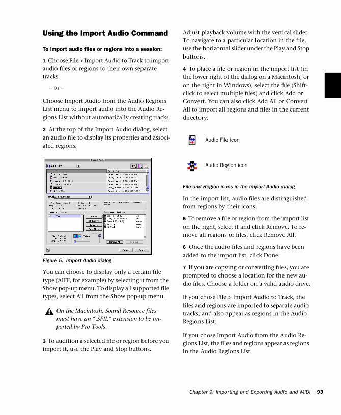
Using the Import Audio Command
To import audio files or regions into a session:
1 Choose File > Import Audio to Track to import audio files or regions to their own separate tracks.
– or –
Choose Import Audio from the Audio Regions List menu to import audio into the Audio Re-gions List without automatically creating tracks.
2 At the top of the Import Audio dialog, select an audio file to display its properties and associ-ated regions.
You can choose to display only a certain file type (AIFF, for example) by selecting it from the Show pop-up menu. To display all supported file types, select All from the Show pop-up menu.
3 To audition a selected file or region before you import it, use the Play and Stop buttons.
Figure 5. Import Audio dialog
On the Macintosh, Sound Resource files must have an “.SFIL” extension to be im-ported by Pro Tools.
Adjust playback volume with the vertical slider. To navigate to a particular location in the file, use the horizontal slider under the Play and Stop buttons.
4 To place a file or region in the import list (in the lower right of the dialog on a Macintosh, or on the right in Windows), select the file (Shift-click to select multiple files) and click Add or Convert. You can also click Add All or Convert All to import all regions and files in the current directory.
In the import list, audio files are distinguished from regions by their icons.
5 To remove a file or region from the import list on the right, select it and click Remove. To re-move all regions or files, click Remove All.
6 Once the audio files and regions have been added to the import list, click Done.
7 If you are copying or converting files, you are prompted to choose a location for the new au-dio files. Choose a folder on a valid audio drive.
If you chose File > Import Audio to Track, the files and regions are imported to separate audio tracks, and also appear as regions in the Audio Regions List.
If you chose Import Audio from the Audio Re-gions List, the files and regions appear as regions in the Audio Regions List.
File and Region icons in the Import Audio dialog
Audio File icon
Audio Region icon
Chap
ter 9: Importing and Exporting Audio and MIDI 93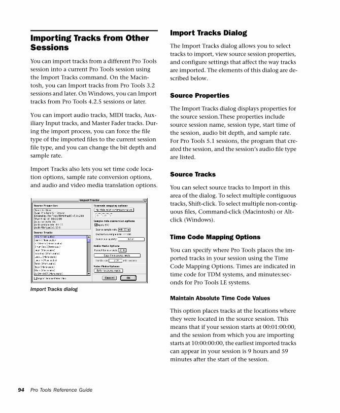
94
Importing Tracks from Other SessionsYou can import tracks from a different Pro Tools session into a current Pro Tools session using the Import Tracks command. On the Macin-tosh, you can Import tracks from Pro Tools 3.2 sessions and later. On Windows, you can Import tracks from Pro Tools 4.2.5 sessions or later.
You can import audio tracks, MIDI tracks, Aux-iliary Input tracks, and Master Fader tracks. Dur-ing the import process, you can force the file type of the imported files to the current session file type, and you can change the bit depth and sample rate.
Import Tracks also lets you set time code loca-tion options, sample rate conversion options, and audio and video media translation options.
Import Tracks dialog
Pro Tools Reference Guide
Import Tracks Dialog
The Import Tracks dialog allows you to select tracks to import, view source session properties, and configure settings that affect the way tracks are imported. The elements of this dialog are de-scribed below.
Source Properties
The Import Tracks dialog displays properties for the source session.These properties include source session name, session type, start time of the session, audio bit depth, and sample rate. For Pro Tools 5.1 sessions, the program that cre-ated the session, and the session’s audio file type are listed.
Source Tracks
You can select source tracks to Import in this area of the dialog. To select multiple contiguous tracks, Shift-click. To select multiple non-contig-uous files, Command-click (Macintosh) or Alt-click (Windows).
Time Code Mapping Options
You can specify where Pro Tools places the im-ported tracks in your session using the Time Code Mapping Options. Times are indicated in time code for TDM systems, and minutes:sec-onds for Pro Tools LE systems.
Maintain Absolute Time Code Values
This option places tracks at the locations where they were located in the source session. This means that if your session starts at 00:01:00:00, and the session from which you are importing starts at 10:00:00:00, the earliest imported tracks can appear in your session is 9 hours and 59 minutes after the start of the session.
Maintain Relative Time Code Values
This option places tracks at the same offset from session start as they had in the source session. For example. if the session start was 01:00:00:00 in the source session and a track started at 01:01:00:00, then if the current session start is 02:00:00:00 the track will be placed at 02:01:00:00.
Map Start Time Code to hh:mm:ss:ff
This option places tracks relative to their origi-nal session start time. This means that if your session starts at 00:01:00:00, and the session from which you are importing tracks starts at 10:00:00:00, you can set the start time code to 00:01:00:00, and avoid placing files 9 hours and 59 minutes from the start of your session.
Sample Rate Conversion Options
This dialog allows you to set options for sample-rate conversion of imported audio files. If the source session and your target session have the same sample rate, this portion of the dialog is dimmed.
Source Sample Rate
Although your audio files are from a 44.1 kHz or 48 kHz session, you can have the sample rate conversion process treat them in several ways to compensate for pull-up, pull-down, and NTSC or PAL frame rates. This setting allows you to choose the sample rate from which you want the sample rate conversion process to start.
Destination Sample Rate
The destination sample rate is always set to the sample rate of your session.
Conversion Quality
With this setting you can change the quality of the sample-rate conversion process. At lower quality settings audio is processed faster; at higher settings audio processing is slower. “Best” runs at approximately real time on a fast machine. See “Conversion Quality” on page 99.
Audio Media Options
Consolidate from Source Media
This option lets you copy audio while consoli-dating it. In this way you can copy only the used portions of the media, without copying unused audio in the source files.
When you choose this option, you should also choose an amount of handle. Handle is an amount of the original audio file that is pre-served before and after each region in case you need to make any edits to the new regions.
Copy from Source Media
This option copies all audio files related to the imported tracks from the source media to a new specified location. This is useful if you are im-porting tracks from a source such as CD-ROM or shared storage, and you want to place the audio files on a different hard drive.
Refer to Source Media (Where Possible)
This setting lets you avoid duplicating audio files by referring to the original files when possi-ble. If the source files do not reside on “play-able” media (such as a CD-ROM), or if they re-quire bit depth or file conversion, the files are instead copied.
Chapter 9: Importing and Exporting Audio and MIDI 95
96
Force Audio Media to New Format
This forces all imported audio files to the audio media format you select.
Format for New Audio
Choose whether you want new media files to be SDII, WAV, or AIFF files.
Video Media Options
You can either choose to leave video media files in their original locations or copy them to a new location. This is useful if you are importing tracks from a source such as CD-ROM or shared storage, and you want to place video files on a different drive.
Import Tempo/Meter Map
Select this option to import the meter and tempo tracks from the source session.
Using the Import Tracks Command
To import tracks:
1 Open or create a new session.
2 Choose File > Import Tracks.
3 Navigate to and select the session to import tracks from and click Open. The Import Tracks dialog opens and displays the tracks that can be imported.
If the current Pro Tools system does not support surround mixing, surround tracks are not dis-played in the Import Tracks dialog.
Pro Tools Reference Guide
4 Select the tracks to import. Shift-click to select multiple contiguous files. Command-click (Macintosh) or Alt-click (Windows) to select multiple non-contiguous files.
5 Choose the time code mapping option for im-ported audio files.
6 If the sample rates of the sessions are different, choose the sample rate for the source session.
7 If applicable, choose options for imported au-dio and video media files.
8 To import the meter and tempo tracks from the source session, select that option.
9 Click OK when you are finished.
10 If you chose to copy or consolidate media, choose a location to place the media files.
Loading Audio Files with Drag & DropPro Tools provides you with a convenient method of batch loading audio files into an open session.
To batch load audio files into a session:
1 Open the Pro Tools session.
2 From the desktop, locate the audio files you want to import. Make sure the files match the session’s file type, bit depth, and sample rate.
3 Drag the audio files onto the Pro Tools icon. The audio files are automatically imported and appear in the Audio Regions List.
Imported tracks are made inactive if their source media is unavailable, of if the cur-rent session does not contain an equivalent output path.
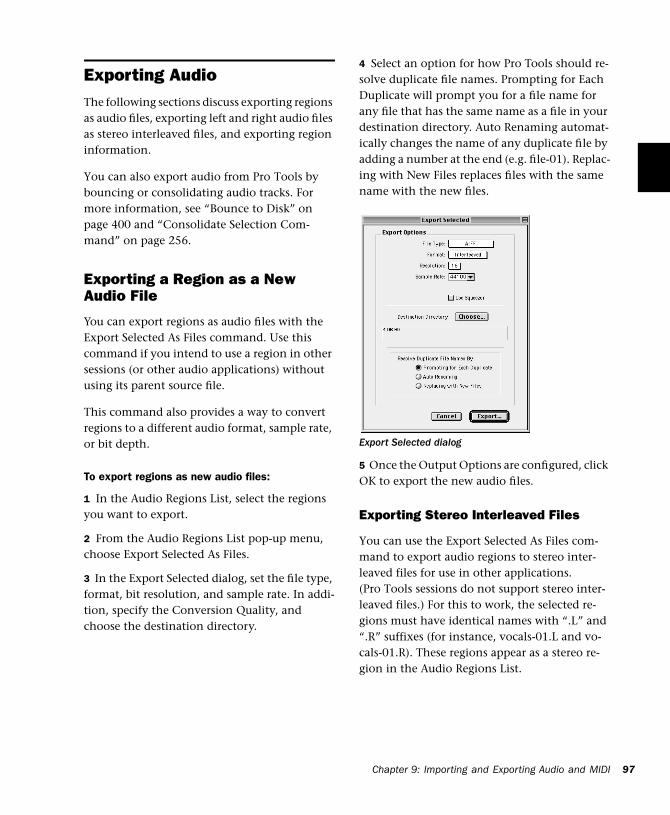
Exporting AudioThe following sections discuss exporting regions as audio files, exporting left and right audio files as stereo interleaved files, and exporting region information.
You can also export audio from Pro Tools by bouncing or consolidating audio tracks. For more information, see “Bounce to Disk” on page 400 and “Consolidate Selection Com-mand” on page 256.
Exporting a Region as a New Audio File
You can export regions as audio files with the Export Selected As Files command. Use this command if you intend to use a region in other sessions (or other audio applications) without using its parent source file.
This command also provides a way to convert regions to a different audio format, sample rate, or bit depth.
To export regions as new audio files:
1 In the Audio Regions List, select the regions you want to export.
2 From the Audio Regions List pop-up menu, choose Export Selected As Files.
3 In the Export Selected dialog, set the file type, format, bit resolution, and sample rate. In addi-tion, specify the Conversion Quality, and choose the destination directory.
4 Select an option for how Pro Tools should re-solve duplicate file names. Prompting for Each Duplicate will prompt you for a file name for any file that has the same name as a file in your destination directory. Auto Renaming automat-ically changes the name of any duplicate file by adding a number at the end (e.g. file-01). Replac-ing with New Files replaces files with the same name with the new files.
5 Once the Output Options are configured, click OK to export the new audio files.
Exporting Stereo Interleaved Files
You can use the Export Selected As Files com-mand to export audio regions to stereo inter-leaved files for use in other applications. (Pro Tools sessions do not support stereo inter-leaved files.) For this to work, the selected re-gions must have identical names with “.L” and “.R” suffixes (for instance, vocals-01.L and vo-cals-01.R). These regions appear as a stereo re-gion in the Audio Regions List.
Export Selected dialog
Chapter 9: Importing and Exporting Audio and MIDI 97
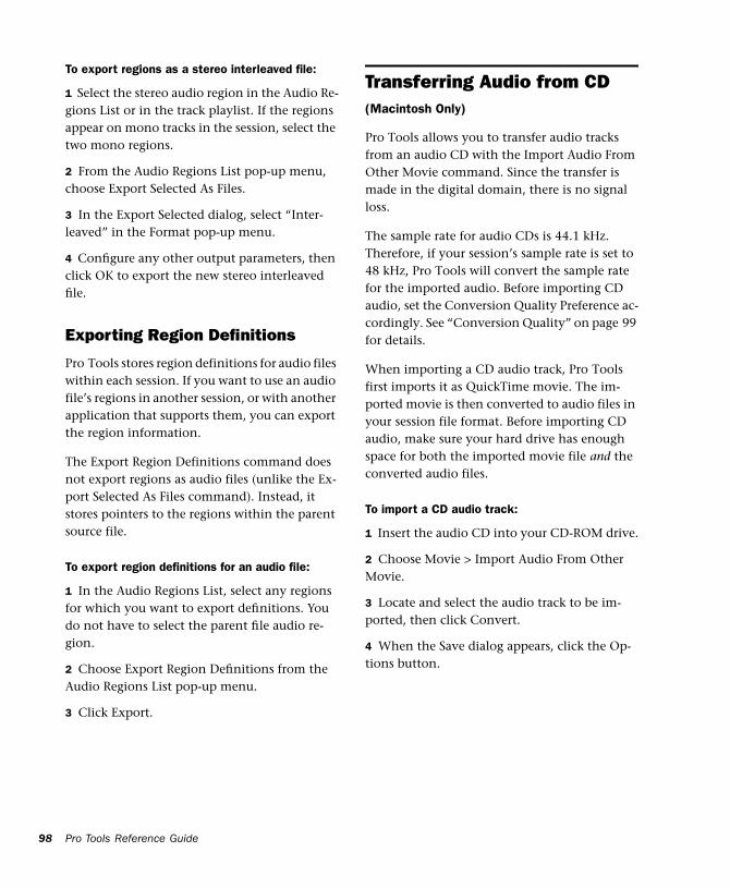
98
To export regions as a stereo interleaved file:
1 Select the stereo audio region in the Audio Re-gions List or in the track playlist. If the regions appear on mono tracks in the session, select the two mono regions.
2 From the Audio Regions List pop-up menu, choose Export Selected As Files.
3 In the Export Selected dialog, select “Inter-leaved” in the Format pop-up menu.
4 Configure any other output parameters, then click OK to export the new stereo interleaved file.
Exporting Region Definitions
Pro Tools stores region definitions for audio files within each session. If you want to use an audio file’s regions in another session, or with another application that supports them, you can export the region information.
The Export Region Definitions command does not export regions as audio files (unlike the Ex-port Selected As Files command). Instead, it stores pointers to the regions within the parent source file.
To export region definitions for an audio file:
1 In the Audio Regions List, select any regions for which you want to export definitions. You do not have to select the parent file audio re-gion.
2 Choose Export Region Definitions from the Audio Regions List pop-up menu.
3 Click Export.
Pro Tools Reference Guide
Transferring Audio from CD(Macintosh Only)
Pro Tools allows you to transfer audio tracks from an audio CD with the Import Audio From Other Movie command. Since the transfer is made in the digital domain, there is no signal loss.
The sample rate for audio CDs is 44.1 kHz. Therefore, if your session’s sample rate is set to 48 kHz, Pro Tools will convert the sample rate for the imported audio. Before importing CD audio, set the Conversion Quality Preference ac-cordingly. See “Conversion Quality” on page 99 for details.
When importing a CD audio track, Pro Tools first imports it as QuickTime movie. The im-ported movie is then converted to audio files in your session file format. Before importing CD audio, make sure your hard drive has enough space for both the imported movie file and the converted audio files.
To import a CD audio track:
1 Insert the audio CD into your CD-ROM drive.
2 Choose Movie > Import Audio From Other Movie.
3 Locate and select the audio track to be im-ported, then click Convert.
4 When the Save dialog appears, click the Op-tions button.
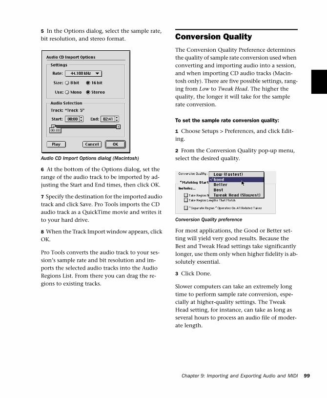
5 In the Options dialog, select the sample rate, bit resolution, and stereo format.
6 At the bottom of the Options dialog, set the range of the audio track to be imported by ad-justing the Start and End times, then click OK.
7 Specify the destination for the imported audio track and click Save. Pro Tools imports the CD audio track as a QuickTime movie and writes it to your hard drive.
8 When the Track Import window appears, click OK.
Pro Tools converts the audio track to your ses-sion’s sample rate and bit resolution and im-ports the selected audio tracks into the Audio Regions List. From there you can drag the re-gions to existing tracks.
Audio CD Import Options dialog (Macintosh)
Conversion QualityThe Conversion Quality Preference determines the quality of sample rate conversion used when converting and importing audio into a session, and when importing CD audio tracks (Macin-tosh only). There are five possible settings, rang-ing from Low to Tweak Head. The higher the quality, the longer it will take for the sample rate conversion.
To set the sample rate conversion quality:
1 Choose Setups > Preferences, and click Edit-ing.
2 From the Conversion Quality pop-up menu, select the desired quality.
For most applications, the Good or Better set-ting will yield very good results. Because the Best and Tweak Head settings take significantly longer, use them only when higher fidelity is ab-solutely essential.
3 Click Done.
Slower computers can take an extremely long time to perform sample rate conversion, espe-cially at higher-quality settings. The Tweak Head setting, for instance, can take as long as several hours to process an audio file of moder-ate length.
Conversion Quality preference
Chapter 9: Importing and Exporting Audio and MIDI 99
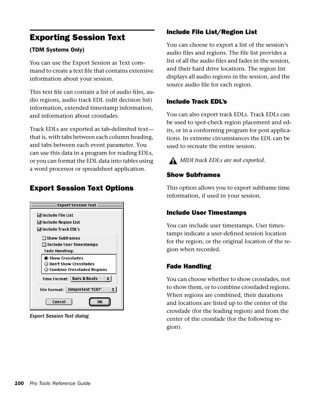
100
Exporting Session Text(TDM Systems Only)
You can use the Export Session as Text com-mand to create a text file that contains extensive information about your session.
This text file can contain a list of audio files, au-dio regions, audio track EDL (edit decision list) information, extended timestamp information, and information about crossfades.
Track EDLs are exported as tab-delimited text—that is, with tabs between each column heading, and tabs between each event parameter. You can use this data in a program for reading EDLs, or you can format the EDL data into tables using a word processor or spreadsheet application.
Export Session Text Options
Export Session Text dialog
Pro Tools Reference Guide
Include File List/Region List
You can choose to export a list of the session’s audio files and regions. The file list provides a list of all the audio files and fades in the session, and their hard drive locations. The region list displays all audio regions in the session, and the source audio file for each region.
Include Track EDL’s
You can also export track EDLs. Track EDLs can be used to spot-check region placement and ed-its, or in a conforming program for post applica-tions. In extreme circumstances the EDL can be used to recreate the entire session.
Show Subframes
This option allows you to export subframe time information, if used in your session.
Include User Timestamps
You can include user timestamps. User times-tamps indicate a user-defined session location for the region, or the original location of the re-gion when recorded.
Fade Handling
You can choose whether to show crossfades, not to show them, or to combine crossfaded regions. When regions are combined, their durations and locations are listed up to the center of the crossfade (for the leading region) and from the center of the crossfade (for the following re-gion).
MIDI track EDLs are not exported.
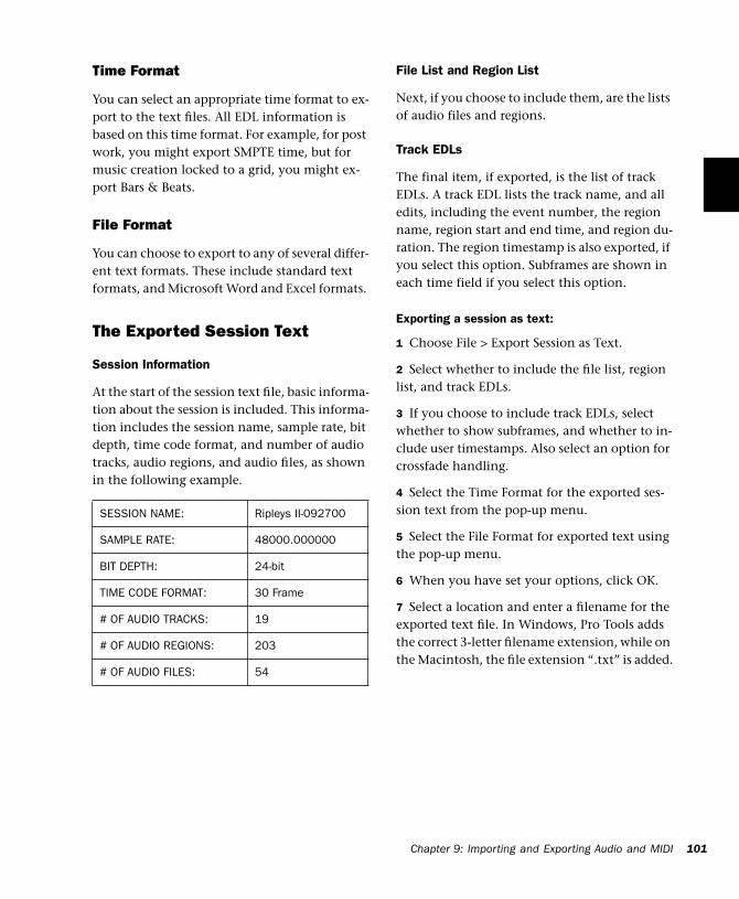
Time Format
You can select an appropriate time format to ex-port to the text files. All EDL information is based on this time format. For example, for post work, you might export SMPTE time, but for music creation locked to a grid, you might ex-port Bars & Beats.
File Format
You can choose to export to any of several differ-ent text formats. These include standard text formats, and Microsoft Word and Excel formats.
The Exported Session Text
Session Information
At the start of the session text file, basic informa-tion about the session is included. This informa-tion includes the session name, sample rate, bit depth, time code format, and number of audio tracks, audio regions, and audio files, as shown in the following example.
SESSION NAME: Ripleys II-092700
SAMPLE RATE: 48000.000000
BIT DEPTH: 24-bit
TIME CODE FORMAT: 30 Frame
# OF AUDIO TRACKS: 19
# OF AUDIO REGIONS: 203
# OF AUDIO FILES: 54
File List and Region List
Next, if you choose to include them, are the lists of audio files and regions.
Track EDLs
The final item, if exported, is the list of track EDLs. A track EDL lists the track name, and all edits, including the event number, the region name, region start and end time, and region du-ration. The region timestamp is also exported, if you select this option. Subframes are shown in each time field if you select this option.
Exporting a session as text:
1 Choose File > Export Session as Text.
2 Select whether to include the file list, region list, and track EDLs.
3 If you choose to include track EDLs, select whether to show subframes, and whether to in-clude user timestamps. Also select an option for crossfade handling.
4 Select the Time Format for the exported ses-sion text from the pop-up menu.
5 Select the File Format for exported text using the pop-up menu.
6 When you have set your options, click OK.
7 Select a location and enter a filename for the exported text file. In Windows, Pro Tools adds the correct 3-letter filename extension, while on the Macintosh, the file extension “.txt” is added.
Chapter 9: Importing and Exporting Audio and MIDI 101
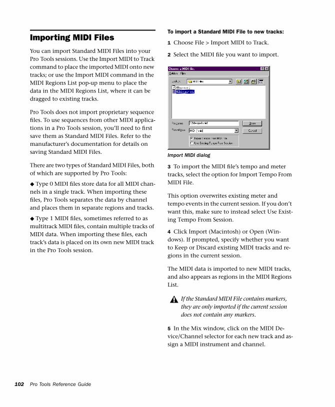
102
Importing MIDI FilesYou can import Standard MIDI Files into your Pro Tools sessions. Use the Import MIDI to Track command to place the imported MIDI onto new tracks; or use the Import MIDI command in the MIDI Regions List pop-up menu to place the data in the MIDI Regions List, where it can be dragged to existing tracks.
Pro Tools does not import proprietary sequence files. To use sequences from other MIDI applica-tions in a Pro Tools session, you’ll need to first save them as Standard MIDI Files. Refer to the manufacturer’s documentation for details on saving Standard MIDI Files.
There are two types of Standard MIDI Files, both of which are supported by Pro Tools:
◆ Type 0 MIDI files store data for all MIDI chan-nels in a single track. When importing these files, Pro Tools separates the data by channel and places them in separate regions and tracks.
◆ Type 1 MIDI files, sometimes referred to as multitrack MIDI files, contain multiple tracks of MIDI data. When importing these files, each track’s data is placed on its own new MIDI track in the Pro Tools session.
Pro Tools Reference Guide
To import a Standard MIDI File to new tracks:
1 Choose File > Import MIDI to Track.
2 Select the MIDI file you want to import.
3 To import the MIDI file’s tempo and meter tracks, select the option for Import Tempo From MIDI File.
This option overwrites existing meter and tempo events in the current session. If you don’t want this, make sure to instead select Use Exist-ing Tempo From Session.
4 Click Import (Macintosh) or Open (Win-dows). If prompted, specify whether you want to Keep or Discard existing MIDI tracks and re-gions in the current session.
The MIDI data is imported to new MIDI tracks, and also appears as regions in the MIDI Regions List.
5 In the Mix window, click on the MIDI De-vice/Channel selector for each new track and as-sign a MIDI instrument and channel.
Import MIDI dialog
If the Standard MIDI File contains markers, they are only imported if the current session does not contain any markers.
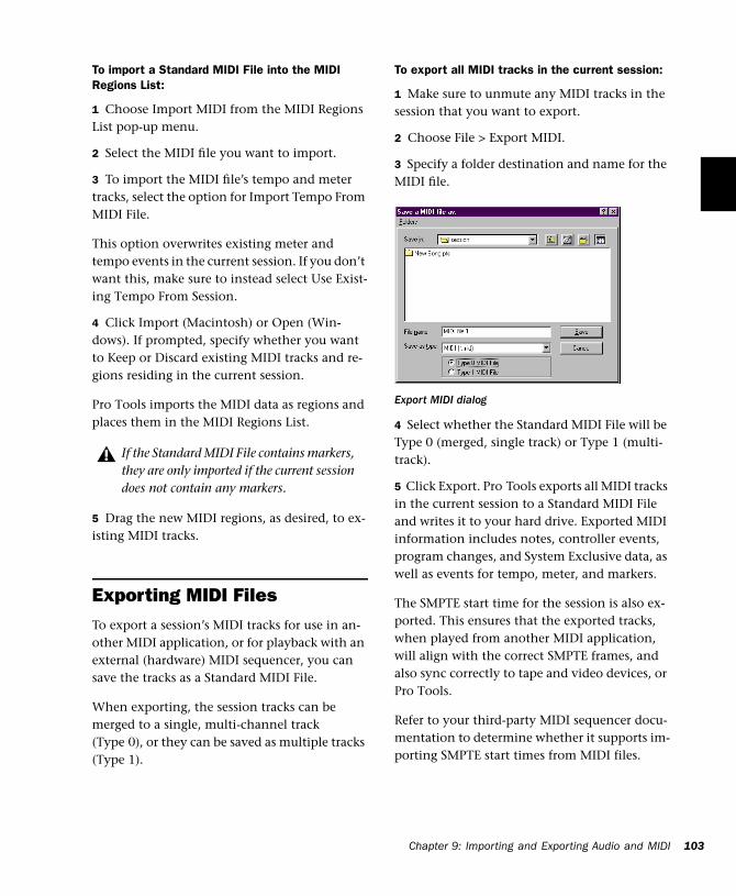
To import a Standard MIDI File into the MIDI Regions List:
1 Choose Import MIDI from the MIDI Regions List pop-up menu.
2 Select the MIDI file you want to import.
3 To import the MIDI file’s tempo and meter tracks, select the option for Import Tempo From MIDI File.
This option overwrites existing meter and tempo events in the current session. If you don’t want this, make sure to instead select Use Exist-ing Tempo From Session.
4 Click Import (Macintosh) or Open (Win-dows). If prompted, specify whether you want to Keep or Discard existing MIDI tracks and re-gions residing in the current session.
Pro Tools imports the MIDI data as regions and places them in the MIDI Regions List.
5 Drag the new MIDI regions, as desired, to ex-isting MIDI tracks.
Exporting MIDI FilesTo export a session’s MIDI tracks for use in an-other MIDI application, or for playback with an external (hardware) MIDI sequencer, you can save the tracks as a Standard MIDI File.
When exporting, the session tracks can be merged to a single, multi-channel track (Type 0), or they can be saved as multiple tracks (Type 1).
If the Standard MIDI File contains markers, they are only imported if the current session does not contain any markers.
To export all MIDI tracks in the current session:
1 Make sure to unmute any MIDI tracks in the session that you want to export.
2 Choose File > Export MIDI.
3 Specify a folder destination and name for the MIDI file.
4 Select whether the Standard MIDI File will be Type 0 (merged, single track) or Type 1 (multi-track).
5 Click Export. Pro Tools exports all MIDI tracks in the current session to a Standard MIDI File and writes it to your hard drive. Exported MIDI information includes notes, controller events, program changes, and System Exclusive data, as well as events for tempo, meter, and markers.
The SMPTE start time for the session is also ex-ported. This ensures that the exported tracks, when played from another MIDI application, will align with the correct SMPTE frames, and also sync correctly to tape and video devices, or Pro Tools.
Refer to your third-party MIDI sequencer docu-mentation to determine whether it supports im-porting SMPTE start times from MIDI files.
Export MIDI dialog
Chapter 9: Importing and Exporting Audio and MIDI 103
104
Not Exported with MIDI Files
Mute automation and muted regions do not af-fect exported MIDI. As long as a track is not muted by clicking its Mute button, all of its MIDI data is exported.
When exporting MIDI files from Pro Tools, de-vice assignments for tracks are not retained (though channel assignments are). If you there-fore export MIDI tracks from Pro Tools and later re-import them, you’ll need to reassign the tracks to the desired devices.
All playlist information for MIDI tracks is lost when exporting. For example, tracks that previ-ously contained dozens of MIDI regions will be flattened and only contain single regions after exporting and re-importing.
Pro Tools Reference Guide
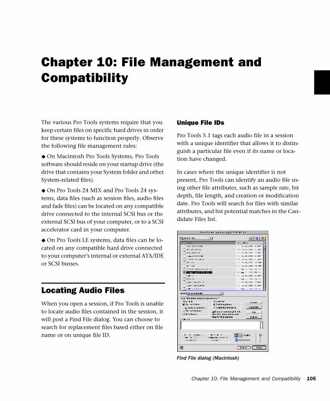
Chapter 10: File Management and Compatibility
The various Pro Tools systems require that you keep certain files on specific hard drives in order for these systems to function properly. Observe the following file management rules:
◆ On Macintosh Pro Tools Systems, Pro Tools software should reside on your startup drive (the drive that contains your System folder and other System-related files).
◆ On Pro Tools 24 MIX and Pro Tools 24 sys-tems, data files (such as session files, audio files and fade files) can be located on any compatible drive connected to the internal SCSI bus or the external SCSI bus of your computer, or to a SCSI accelerator card in your computer.
◆ On Pro Tools LE systems, data files can be lo-cated on any compatible hard drive connected to your computer’s internal or external ATA/IDE or SCSI busses.
Locating Audio FilesWhen you open a session, if Pro Tools is unable to locate audio files contained in the session, it will post a Find File dialog. You can choose to search for replacement files based either on file name or on unique file ID.
Unique File IDs
Pro Tools 5.1 tags each audio file in a session with a unique identifier that allows it to distin-guish a particular file even if its name or loca-tion have changed.
In cases where the unique identifier is not present, Pro Tools can identify an audio file us-ing other file attributes, such as sample rate, bit depth, file length, and creation or modification date. Pro Tools will search for files with similar attributes, and list potential matches in the Can-didate Files list.
Find File dialog (Macintosh)
Chapter 10: File Management and Compatibility 105
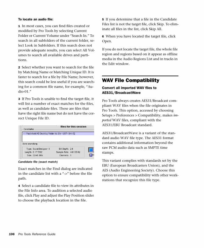
106
To locate an audio file:
1 In most cases, you can find files created or modified by Pro Tools by selecting Current Folder or Current Volume under “Search In.” To search in all subfolders of the current folder, se-lect Look in Subfolders. If this search does not provide adequate results, you can select All Vol-umes to search all available drives and parti-tions.
2 Select whether you want to search for the file by Matching Name or Matching Unique ID. It is faster to search for a file by File Name; however, this search could be less useful if you are search-ing for a common file name, for example, “Au-dio-01.”
3 If Pro Tools is unable to find the target file, it will list a number of exact matches for the files, as well as candidate files. These are files that have the right file name but do not have the cor-rect Unique File ID.
Exact matches in the Find dialog are indicated in the candidate list with a “->” before the file path.
4 Select a candidate file to view its attributes in the File Info area. To audition a selected audio file, click Play and adjust the Play Position slider to choose the playback location in the file.
Candidate file (exact match)
Pro Tools Reference Guide
5 If you determine that a file in the Candidate Files list is not the target file, click Skip. To elim-inate all files in the list, click Skip All.
6 When you have located the target file, click Open.
If you do not locate the target file, the whole file region and regions based on it appear as offline media in the Audio Regions List and in tracks in the Edit window.
WAV File CompatibilityConvert all imported WAV files to AES31/BroadcastWave
Pro Tools always creates AES31/Broadcast com-pliant WAV files when the file originates in Pro Tools. This option, accessed by choosing Setups > Preferences > Compatibility, makes im-ported WAV files, compliant with the AES31/EBU Broadcast standard.
AES31/BroadcastWave is a variant of the stan-dard audio WAV file type. The AES31 format contains additional information beyond the raw PCM audio data such as SMPTE time stamps.
This variant complies with standards set by the EBU (European Broadcasters Union), and the AES (Audio Engineering Society). Choose this option to ensure compatibility with other work-stations that recognize this file type.
Avid File CompatibilityWhen Avid Compatibility preference is enabled, Pro Tools adds additional “metadata” when bouncing to disk, or when recording from a bus. This metadata includes the name of session, and the name of the source of the bounce (bus or track output). When the bounced file is opened from an Avid system, the metadata information will help identify the source of the file compo-nents.
In addition, when this Avid Compatibility is en-abled, it forces all OMF media to be treated as Read Only within Pro Tools
Creating Mac and PC Compatible Sessions The Enforce Mac/PC Compatibility option al-lows you to create and save Pro Tools sessions that are compatible on both Macintosh and Windows. This option is available when creat-ing a new 5.1 session, or when saving a copy of a 5.1 session.
Cross-Platform Session Limits
Audio File Types
Sound Designer II (SDII) files cannot be read by Windows systems. Therefore, when creating Mac and Windows compatible session files, the audio file type for the session must be either AIFF or WAV.
File Name Extensions
For cross-platform compatibility, all files in a session must have a 3-letter file extension added to the file name. Pro Tools 5.1 session files have the extension “.pts,” and Pro Tools 5 sessions have the extension “.pt5.” WAV files have the “.wav” file extension, and AIFF files have the “.aif” file extension.
Incompatible ASCII Characters
Region names, track names, file names, and Plug-In settings cannot use ASCII characters that are incompatible with either system.
When creating a new name, if an incompatibil-ity is detected when Mac/PC Compatibility mode is enabled, a dialog will appear that prompts you to type a new name. When you im-port files into a session that is set for Mac/Win-dows compatibility, incompatible characters are converted to underscores (“_”).
The following characters cannot be used in Mac/Windows compatible sessions:
/ (slash)
\ (backslash)
: (colon)
* (asterisk)
? (question mark)
“ (quotation marks)
< (less-than symbol)
> (greater-than symbol)
| (vertical line or pipe)
Any character typed with the Command key
Chapter 10: File Management and Compatibility 107

108
To create a session that is compatible with Macintosh and Windows:
1 After launching Pro Tools, choose File > New Session.
2 Choose the drive where you want to save the session. The session should be created on a ded-icated audio drive.
3 In the New Session dialog, set the Audio File Type to AIFF or WAV. These file formats are com-patible with either platform.
4 Set the Bit Depth and Sample Rate for the ses-sion.
5 Select “Enforce Mac/PC Compatibility” (Mac-intosh) or “Enforce PC/Mac Compatibility” (Windows). This option must be selected to make the session cross-platform compatible.
6 Select the I/O Settings to use for the session. Several pre-configured I/O Settings are included with your system, or you can choose custom I/O Settings that you have created. See Chapter 7, “I/O Setup” for more information.
7 Enter a name for the session and click Save.
To save an existing session that is compatible with Macintosh and Windows:
1 Choose File > Save Session Copy In.
2 In the Save Session Copy dialog, set the Audio File Type to AIFF or WAV. These file formats are compatible with either platform.
3 Set the Bit Depth and Sample Rate for the ses-sion, as well as any options Items To Copy.
4 Select “Enforce Mac/PC Compatibility” (Mac-intosh) or “Enforce PC/Mac Compatibility” (Windows). This option must be selected to make the session cross-platform compatible.
Pro Tools Reference Guide
5 Choose a destination and enter a name for the new session file. then click Save.
If the session previously used SDII files, the files are converted to the new audio file format.
Part III: Recording
109

110
Chapter 11: Record Setup
Before you start recording, make sure your Pro Tools system is connected and configured properly. For details on connecting Pro Tools to your studio, refer to the Pro Tools Installation Guide that came with your system.
While some of the information in this chapter is relevant to recording MIDI, there are more spe-cific setup details for MIDI recording in Chapter 13, “MIDI Recording.”
Input Connections and Audio LevelsMost Digidesign audio interfaces operate as line-level devices and offer no pre-amplification. You must therefore adjust the level of an input signal to line level before it reaches Pro Tools. Low-level sources like microphones and electric guitars need to be pre-amplified. You can do this with a quality mixing board or dedicated preamp.
NOTE: The Digi 001 is an exception to this rule. Its I/O Box has two inputs with preamps, to which you can connect low-level signals, and six addi-tional inputs with “input gain.”
Volume and pan controls for tracks in Pro Tools only affect monitoring levels—not the record-ing input gain. The LED indicators on audio in-terfaces indicate both full-code (highest level be-fore clipping) and true clipping of Pro Tools output signals. The on-screen meters in the Pro Tools application indicate only true clip-ping.
Digital Clipping
Clipping occurs when you feed a signal to a re-corder or mixer that is louder or “hotter” than the device allows. On many analog tape decks, a little clipping adds a perceived warmth to the sound due to tape compression. In digital re-cording, however, clipping causes digital distor-tion, which is undesirable and should always be avoided.
Set Input Levels High But Don’t Clip
When you feed a signal into any audio record-ing system, including Pro Tools, you need to ad-just the input level to optimize the dynamic range. Adjust the input signal to register as high as possible on your input meter without trigger-ing the clipping indicator. If the input level is too low, you will not take full advantage of the dynamic range of your Pro Tools system. If the input level is too high, however, it will be clipped.
Chapter 11: Record Setup 111
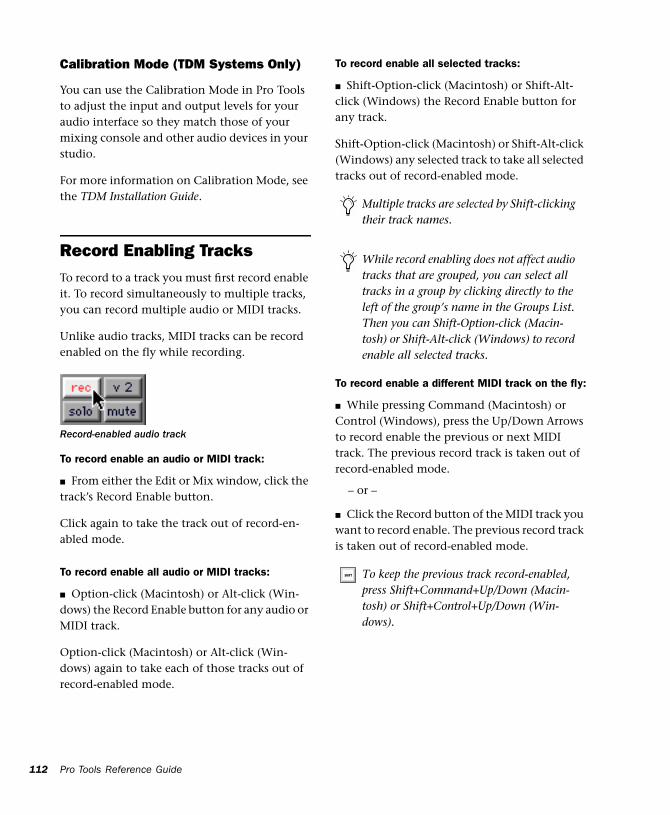
112
Calibration Mode (TDM Systems Only)
You can use the Calibration Mode in Pro Tools to adjust the input and output levels for your audio interface so they match those of your mixing console and other audio devices in your studio.
For more information on Calibration Mode, see the TDM Installation Guide.
Record Enabling TracksTo record to a track you must first record enable it. To record simultaneously to multiple tracks, you can record multiple audio or MIDI tracks.
Unlike audio tracks, MIDI tracks can be record enabled on the fly while recording.
To record enable an audio or MIDI track:
■ From either the Edit or Mix window, click the track’s Record Enable button.
Click again to take the track out of record-en-abled mode.
To record enable all audio or MIDI tracks:
■ Option-click (Macintosh) or Alt-click (Win-dows) the Record Enable button for any audio or MIDI track.
Option-click (Macintosh) or Alt-click (Win-dows) again to take each of those tracks out of record-enabled mode.
Record-enabled audio track
Pro Tools Reference Guide
To record enable all selected tracks:
■ Shift-Option-click (Macintosh) or Shift-Alt-click (Windows) the Record Enable button for any track.
Shift-Option-click (Macintosh) or Shift-Alt-click (Windows) any selected track to take all selected tracks out of record-enabled mode.
To record enable a different MIDI track on the fly:
■ While pressing Command (Macintosh) or Control (Windows), press the Up/Down Arrows to record enable the previous or next MIDI track. The previous record track is taken out of record-enabled mode.
– or –
■ Click the Record button of the MIDI track you want to record enable. The previous record track is taken out of record-enabled mode.
Multiple tracks are selected by Shift-clicking their track names.
While record enabling does not affect audio tracks that are grouped, you can select all tracks in a group by clicking directly to the left of the group’s name in the Groups List. Then you can Shift-Option-click (Macin-tosh) or Shift-Alt-click (Windows) to record enable all selected tracks.
To keep the previous track record-enabled, press Shift+Command+Up/Down (Macin-tosh) or Shift+Control+Up/Down (Win-dows).
Latch Record Mode
When the option for Latch Record Enable But-tons is selected (in the Operations Preferences), you can record enable (latch) additional tracks by clicking their Record Enable buttons. Previ-ously record-enabled tracks remain record-en-abled.
When Latch Record Enable Buttons is dese-lected, record enabling a subsequent track takes the previously record-enabled track out of record-enabled mode.
Record Safe Mode
When tracks are in Record Safe mode, it is not possible to record enable them, and therefore not possible to record to them. Use Record Safe mode to protect important track recordings.
To put an audio or MIDI track in Record Safe mode:
■ Command-click (Macintosh) or Control-click (Windows) the track’s Record Enable button.
Command-click (Macintosh) or Control-click (Windows) again to take the track out of Record Safe mode.
To put all tracks in Record Safe mode:
■ Command-Option-click (Macintosh) or Con-trol-Alt-click (Windows) the Record Enable but-ton on any track.
Command-Option-click (Macintosh) or Con-trol-Alt-click (Windows) again to take all tracks out of Record Safe mode.
When the option for Latch Record Enable Buttons is deselected, you can still Shift-click the Record Enable buttons on multiple tracks to record enable them.
To put all currently selected tracks into Record Safe mode:
■ Command-Option-Shift-click (Macintosh) or Control-Alt-Shift-click (Windows) the Record Enable button on any of the selected tracks to toggle them in and out of Record Safe mode.
Monitoring ModesPro Tools offers two modes of input monitoring, Auto Input Monitoring or Input Only Monitoring (chosen from the Operations menu), which de-termine how input signals are monitored while recording audio.
Auto Input Monitoring
In this mode, when session playback is stopped, Pro Tools monitors audio input. When playback is started for a punch-in, Pro Tools monitors ex-isting track material up until the punch point. While punched in, the input signal is moni-tored. On punch-out, monitoring switches back to the existing track material. This is similar to the auto-switching logic found on digital and analog multitrack tape machines.
When Auto Input Monitoring is enabled, the Record button in the Transport window appears normally gray.
NOTE: When using Auto Input Monitoring, the switch back to monitoring track material on punch-out is not instantaneous. To get instantaneous monitor switching on punch-out, use QuickPunch (see “Using QuickPunch” on page 155).
Chapter 11: Record Setup 113
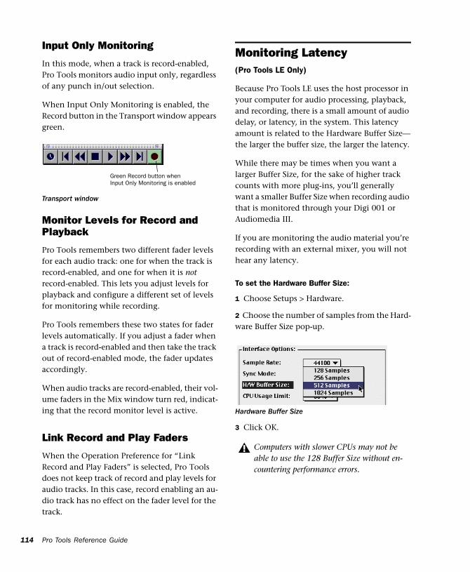
114
Input Only Monitoring
In this mode, when a track is record-enabled, Pro Tools monitors audio input only, regardless of any punch in/out selection.
When Input Only Monitoring is enabled, the Record button in the Transport window appears green.
Monitor Levels for Record and Playback
Pro Tools remembers two different fader levels for each audio track: one for when the track is record-enabled, and one for when it is not record-enabled. This lets you adjust levels for playback and configure a different set of levels for monitoring while recording.
Pro Tools remembers these two states for fader levels automatically. If you adjust a fader when a track is record-enabled and then take the track out of record-enabled mode, the fader updates accordingly.
When audio tracks are record-enabled, their vol-ume faders in the Mix window turn red, indicat-ing that the record monitor level is active.
Link Record and Play Faders
When the Operation Preference for “Link Record and Play Faders” is selected, Pro Tools does not keep track of record and play levels for audio tracks. In this case, record enabling an au-dio track has no effect on the fader level for the track.
Transport window
Green Record button when Input Only Monitoring is enabled
Pro Tools Reference Guide
Monitoring Latency(Pro Tools LE Only)
Because Pro Tools LE uses the host processor in your computer for audio processing, playback, and recording, there is a small amount of audio delay, or latency, in the system. This latency amount is related to the Hardware Buffer Size—the larger the buffer size, the larger the latency.
While there may be times when you want a larger Buffer Size, for the sake of higher track counts with more plug-ins, you’ll generally want a smaller Buffer Size when recording audio that is monitored through your Digi 001 or Audiomedia III.
If you are monitoring the audio material you’re recording with an external mixer, you will not hear any latency.
To set the Hardware Buffer Size:
1 Choose Setups > Hardware.
2 Choose the number of samples from the Hard-ware Buffer Size pop-up.
3 Click OK.
Hardware Buffer Size
Computers with slower CPUs may not be able to use the 128 Buffer Size without en-countering performance errors.
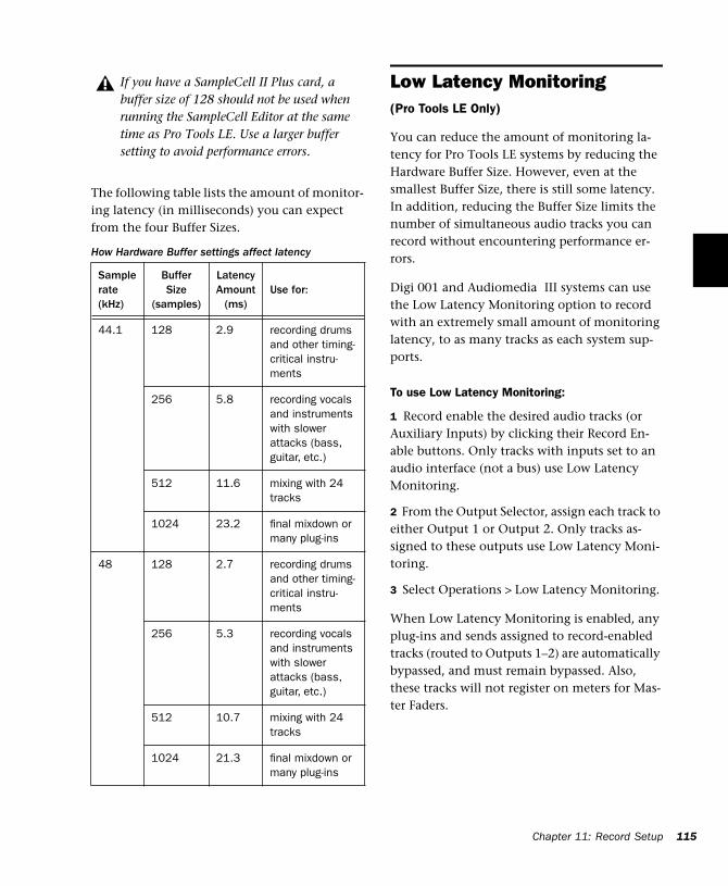
The following table lists the amount of monitor-ing latency (in milliseconds) you can expect from the four Buffer Sizes.
If you have a SampleCell II Plus card, a buffer size of 128 should not be used when running the SampleCell Editor at the same time as Pro Tools LE. Use a larger buffer setting to avoid performance errors.
How Hardware Buffer settings affect latency
Sample rate(kHz)
Buffer Size
(samples)
Latency Amount
(ms)Use for:
44.1 128 2.9 recording drums and other timing-critical instru-ments
256 5.8 recording vocals and instruments with slower attacks (bass, guitar, etc.)
512 11.6 mixing with 24 tracks
1024 23.2 final mixdown or many plug-ins
48 128 2.7 recording drums and other timing-critical instru-ments
256 5.3 recording vocals and instruments with slower attacks (bass, guitar, etc.)
512 10.7 mixing with 24 tracks
1024 21.3 final mixdown or many plug-ins
Low Latency Monitoring(Pro Tools LE Only)
You can reduce the amount of monitoring la-tency for Pro Tools LE systems by reducing the Hardware Buffer Size. However, even at the smallest Buffer Size, there is still some latency. In addition, reducing the Buffer Size limits the number of simultaneous audio tracks you can record without encountering performance er-rors.
Digi 001 and Audiomedia III systems can use the Low Latency Monitoring option to record with an extremely small amount of monitoring latency, to as many tracks as each system sup-ports.
To use Low Latency Monitoring:
1 Record enable the desired audio tracks (or Auxiliary Inputs) by clicking their Record En-able buttons. Only tracks with inputs set to an audio interface (not a bus) use Low Latency Monitoring.
2 From the Output Selector, assign each track to either Output 1 or Output 2. Only tracks as-signed to these outputs use Low Latency Moni-toring.
3 Select Operations > Low Latency Monitoring.
When Low Latency Monitoring is enabled, any plug-ins and sends assigned to record-enabled tracks (routed to Outputs 1–2) are automatically bypassed, and must remain bypassed. Also, these tracks will not register on meters for Mas-ter Faders.
Chapter 11: Record Setup 115
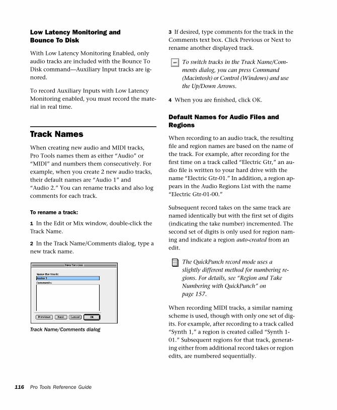
116
Low Latency Monitoring and Bounce To Disk
With Low Latency Monitoring Enabled, only audio tracks are included with the Bounce To Disk command—Auxiliary Input tracks are ig-nored.
To record Auxiliary Inputs with Low Latency Monitoring enabled, you must record the mate-rial in real time.
Track NamesWhen creating new audio and MIDI tracks, Pro Tools names them as either “Audio” or “MIDI” and numbers them consecutively. For example, when you create 2 new audio tracks, their default names are “Audio 1” and “Audio 2.” You can rename tracks and also log comments for each track.
To rename a track:
1 In the Edit or Mix window, double-click the Track Name.
2 In the Track Name/Comments dialog, type a new track name.
Track Name/Comments dialog
Pro Tools Reference Guide
3 If desired, type comments for the track in the Comments text box. Click Previous or Next to rename another displayed track.
4 When you are finished, click OK.
Default Names for Audio Files and Regions
When recording to an audio track, the resulting file and region names are based on the name of the track. For example, after recording for the first time on a track called “Electric Gtr,” an au-dio file is written to your hard drive with the name “Electric Gtr-01.” In addition, a region ap-pears in the Audio Regions List with the name “Electric Gtr-01-00.”
Subsequent record takes on the same track are named identically but with the first set of digits (indicating the take number) incremented. The second set of digits is only used for region nam-ing and indicate a region auto-created from an edit.
When recording MIDI tracks, a similar naming scheme is used, though with only one set of dig-its. For example, after recording to a track called “Synth 1,” a region is created called “Synth 1-01.” Subsequent regions for that track, generat-ing either from additional record takes or region edits, are numbered sequentially.
To switch tracks in the Track Name/Com-ments dialog, you can press Command (Macintosh) or Control (Windows) and use the Up/Down Arrows.
The QuickPunch record mode uses a slightly different method for numbering re-gions. For details, see “Region and Take Numbering with QuickPunch” on page 157.
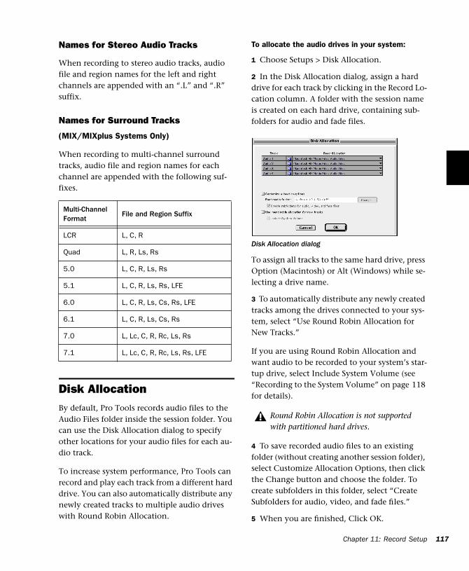
Names for Stereo Audio Tracks
When recording to stereo audio tracks, audio file and region names for the left and right channels are appended with an “.L” and “.R” suffix.
Names for Surround Tracks
(MIX/MIXplus Systems Only)
When recording to multi-channel surround tracks, audio file and region names for each channel are appended with the following suf-fixes.
Disk AllocationBy default, Pro Tools records audio files to the Audio Files folder inside the session folder. You can use the Disk Allocation dialog to specify other locations for your audio files for each au-dio track.
To increase system performance, Pro Tools can record and play each track from a different hard drive. You can also automatically distribute any newly created tracks to multiple audio drives with Round Robin Allocation.
Multi-Channel Format
File and Region Suffix
LCR L, C, R
Quad L, R, Ls, Rs
5.0 L, C, R, Ls, Rs
5.1 L, C, R, Ls, Rs, LFE
6.0 L, C, R, Ls, Cs, Rs, LFE
6.1 L, C, R, Ls, Cs, Rs
7.0 L, Lc, C, R, Rc, Ls, Rs
7.1 L, Lc, C, R, Rc, Ls, Rs, LFE
To allocate the audio drives in your system:
1 Choose Setups > Disk Allocation.
2 In the Disk Allocation dialog, assign a hard drive for each track by clicking in the Record Lo-cation column. A folder with the session name is created on each hard drive, containing sub-folders for audio and fade files.
To assign all tracks to the same hard drive, press Option (Macintosh) or Alt (Windows) while se-lecting a drive name.
3 To automatically distribute any newly created tracks among the drives connected to your sys-tem, select “Use Round Robin Allocation for New Tracks.”
If you are using Round Robin Allocation and want audio to be recorded to your system’s star-tup drive, select Include System Volume (see “Recording to the System Volume” on page 118 for details).
4 To save recorded audio files to an existing folder (without creating another session folder), select Customize Allocation Options, then click the Change button and choose the folder. To create subfolders in this folder, select “Create Subfolders for audio, video, and fade files.”
5 When you are finished, Click OK.
Disk Allocation dialog
Round Robin Allocation is not supported with partitioned hard drives.
Chapter 11: Record Setup 117
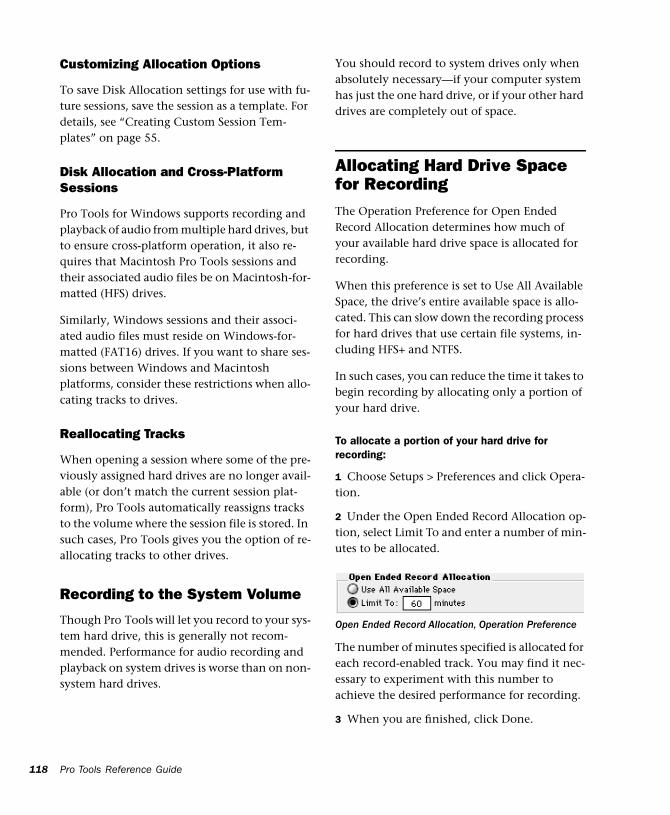
118
Customizing Allocation Options
To save Disk Allocation settings for use with fu-ture sessions, save the session as a template. For details, see “Creating Custom Session Tem-plates” on page 55.
Disk Allocation and Cross-Platform Sessions
Pro Tools for Windows supports recording and playback of audio from multiple hard drives, but to ensure cross-platform operation, it also re-quires that Macintosh Pro Tools sessions and their associated audio files be on Macintosh-for-matted (HFS) drives.
Similarly, Windows sessions and their associ-ated audio files must reside on Windows-for-matted (FAT16) drives. If you want to share ses-sions between Windows and Macintosh platforms, consider these restrictions when allo-cating tracks to drives.
Reallocating Tracks
When opening a session where some of the pre-viously assigned hard drives are no longer avail-able (or don’t match the current session plat-form), Pro Tools automatically reassigns tracks to the volume where the session file is stored. In such cases, Pro Tools gives you the option of re-allocating tracks to other drives.
Recording to the System Volume
Though Pro Tools will let you record to your sys-tem hard drive, this is generally not recom-mended. Performance for audio recording and playback on system drives is worse than on non-system hard drives.
Pro Tools Reference Guide
You should record to system drives only when absolutely necessary—if your computer system has just the one hard drive, or if your other hard drives are completely out of space.
Allocating Hard Drive Space for RecordingThe Operation Preference for Open Ended Record Allocation determines how much of your available hard drive space is allocated for recording.
When this preference is set to Use All Available Space, the drive’s entire available space is allo-cated. This can slow down the recording process for hard drives that use certain file systems, in-cluding HFS+ and NTFS.
In such cases, you can reduce the time it takes to begin recording by allocating only a portion of your hard drive.
To allocate a portion of your hard drive for recording:
1 Choose Setups > Preferences and click Opera-tion.
2 Under the Open Ended Record Allocation op-tion, select Limit To and enter a number of min-utes to be allocated.
The number of minutes specified is allocated for each record-enabled track. You may find it nec-essary to experiment with this number to achieve the desired performance for recording.
3 When you are finished, click Done.
Open Ended Record Allocation, Operation Preference
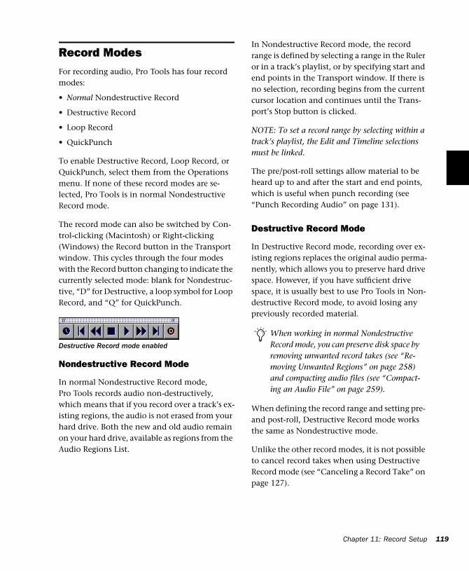
Record ModesFor recording audio, Pro Tools has four record modes:
• Normal Nondestructive Record
• Destructive Record
• Loop Record
• QuickPunch
To enable Destructive Record, Loop Record, or QuickPunch, select them from the Operations menu. If none of these record modes are se-lected, Pro Tools is in normal Nondestructive Record mode.
The record mode can also be switched by Con-trol-clicking (Macintosh) or Right-clicking (Windows) the Record button in the Transport window. This cycles through the four modes with the Record button changing to indicate the currently selected mode: blank for Nondestruc-tive, “D” for Destructive, a loop symbol for Loop Record, and “Q” for QuickPunch.
Nondestructive Record Mode
In normal Nondestructive Record mode, Pro Tools records audio non-destructively, which means that if you record over a track’s ex-isting regions, the audio is not erased from your hard drive. Both the new and old audio remain on your hard drive, available as regions from the Audio Regions List.
Destructive Record mode enabled
In Nondestructive Record mode, the record range is defined by selecting a range in the Ruler or in a track’s playlist, or by specifying start and end points in the Transport window. If there is no selection, recording begins from the current cursor location and continues until the Trans-port’s Stop button is clicked.
NOTE: To set a record range by selecting within a track’s playlist, the Edit and Timeline selections must be linked.
The pre/post-roll settings allow material to be heard up to and after the start and end points, which is useful when punch recording (see “Punch Recording Audio” on page 131).
Destructive Record Mode
In Destructive Record mode, recording over ex-isting regions replaces the original audio perma-nently, which allows you to preserve hard drive space. However, if you have sufficient drive space, it is usually best to use Pro Tools in Non-destructive Record mode, to avoid losing any previously recorded material.
When defining the record range and setting pre- and post-roll, Destructive Record mode works the same as Nondestructive mode.
Unlike the other record modes, it is not possible to cancel record takes when using Destructive Record mode (see “Canceling a Record Take” on page 127).
When working in normal Nondestructive Record mode, you can preserve disk space by removing unwanted record takes (see “Re-moving Unwanted Regions” on page 258) and compacting audio files (see “Compact-ing an Audio File” on page 259).
Chapter 11: Record Setup 119
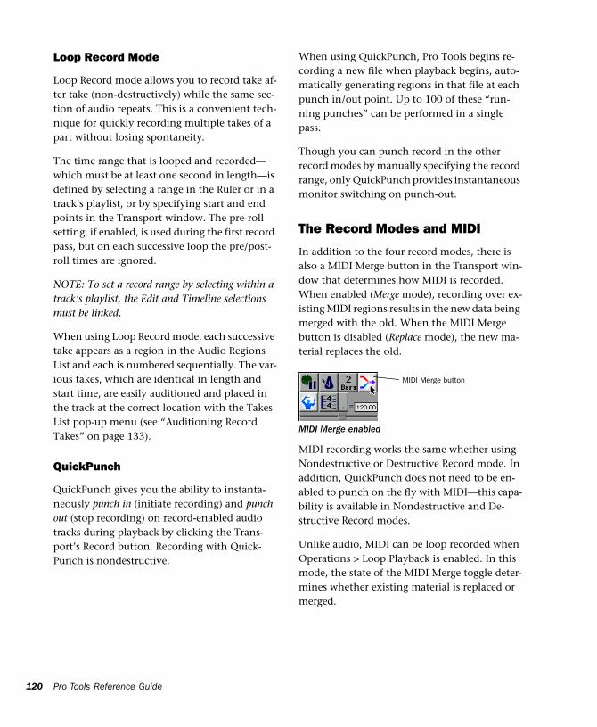
120
Loop Record Mode
Loop Record mode allows you to record take af-ter take (non-destructively) while the same sec-tion of audio repeats. This is a convenient tech-nique for quickly recording multiple takes of a part without losing spontaneity.
The time range that is looped and recorded—which must be at least one second in length—is defined by selecting a range in the Ruler or in a track’s playlist, or by specifying start and end points in the Transport window. The pre-roll setting, if enabled, is used during the first record pass, but on each successive loop the pre/post-roll times are ignored.
NOTE: To set a record range by selecting within a track’s playlist, the Edit and Timeline selections must be linked.
When using Loop Record mode, each successive take appears as a region in the Audio Regions List and each is numbered sequentially. The var-ious takes, which are identical in length and start time, are easily auditioned and placed in the track at the correct location with the Takes List pop-up menu (see “Auditioning Record Takes” on page 133).
QuickPunch
QuickPunch gives you the ability to instanta-neously punch in (initiate recording) and punch out (stop recording) on record-enabled audio tracks during playback by clicking the Trans-port’s Record button. Recording with Quick-Punch is nondestructive.
Pro Tools Reference Guide
When using QuickPunch, Pro Tools begins re-cording a new file when playback begins, auto-matically generating regions in that file at each punch in/out point. Up to 100 of these “run-ning punches” can be performed in a single pass.
Though you can punch record in the other record modes by manually specifying the record range, only QuickPunch provides instantaneous monitor switching on punch-out.
The Record Modes and MIDI
In addition to the four record modes, there is also a MIDI Merge button in the Transport win-dow that determines how MIDI is recorded. When enabled (Merge mode), recording over ex-isting MIDI regions results in the new data being merged with the old. When the MIDI Merge button is disabled (Replace mode), the new ma-terial replaces the old.
MIDI recording works the same whether using Nondestructive or Destructive Record mode. In addition, QuickPunch does not need to be en-abled to punch on the fly with MIDI—this capa-bility is available in Nondestructive and De-structive Record modes.
Unlike audio, MIDI can be loop recorded when Operations > Loop Playback is enabled. In this mode, the state of the MIDI Merge toggle deter-mines whether existing material is replaced or merged.
MIDI Merge enabled
MIDI Merge button
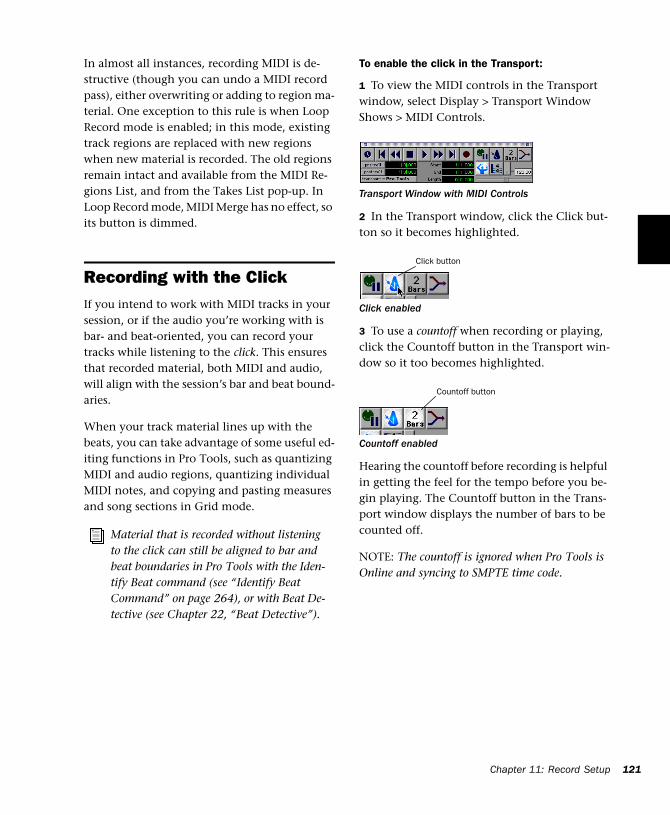
In almost all instances, recording MIDI is de-structive (though you can undo a MIDI record pass), either overwriting or adding to region ma-terial. One exception to this rule is when Loop Record mode is enabled; in this mode, existing track regions are replaced with new regions when new material is recorded. The old regions remain intact and available from the MIDI Re-gions List, and from the Takes List pop-up. In Loop Record mode, MIDI Merge has no effect, so its button is dimmed.
Recording with the ClickIf you intend to work with MIDI tracks in your session, or if the audio you’re working with is bar- and beat-oriented, you can record your tracks while listening to the click. This ensures that recorded material, both MIDI and audio, will align with the session’s bar and beat bound-aries.
When your track material lines up with the beats, you can take advantage of some useful ed-iting functions in Pro Tools, such as quantizing MIDI and audio regions, quantizing individual MIDI notes, and copying and pasting measures and song sections in Grid mode.
Material that is recorded without listening to the click can still be aligned to bar and beat boundaries in Pro Tools with the Iden-tify Beat command (see “Identify Beat Command” on page 264), or with Beat De-tective (see Chapter 22, “Beat Detective”).
To enable the click in the Transport:
1 To view the MIDI controls in the Transport window, select Display > Transport Window Shows > MIDI Controls.
2 In the Transport window, click the Click but-ton so it becomes highlighted.
3 To use a countoff when recording or playing, click the Countoff button in the Transport win-dow so it too becomes highlighted.
Hearing the countoff before recording is helpful in getting the feel for the tempo before you be-gin playing. The Countoff button in the Trans-port window displays the number of bars to be counted off.
NOTE: The countoff is ignored when Pro Tools is Online and syncing to SMPTE time code.
Transport Window with MIDI Controls
Click enabled
Countoff enabled
Click button
Countoff button
Chapter 11: Record Setup 121
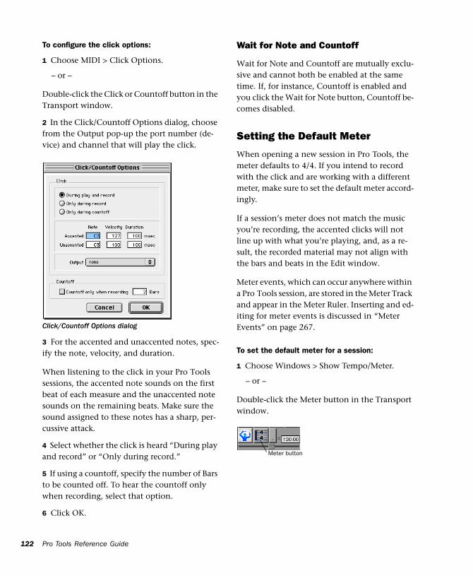
122
To configure the click options:
1 Choose MIDI > Click Options.
– or –
Double-click the Click or Countoff button in the Transport window.
2 In the Click/Countoff Options dialog, choose from the Output pop-up the port number (de-vice) and channel that will play the click.
3 For the accented and unaccented notes, spec-ify the note, velocity, and duration.
When listening to the click in your Pro Tools sessions, the accented note sounds on the first beat of each measure and the unaccented note sounds on the remaining beats. Make sure the sound assigned to these notes has a sharp, per-cussive attack.
4 Select whether the click is heard “During play and record” or “Only during record.”
5 If using a countoff, specify the number of Bars to be counted off. To hear the countoff only when recording, select that option.
6 Click OK.
Click/Countoff Options dialog
Pro Tools Reference Guide
Wait for Note and Countoff
Wait for Note and Countoff are mutually exclu-sive and cannot both be enabled at the same time. If, for instance, Countoff is enabled and you click the Wait for Note button, Countoff be-comes disabled.
Setting the Default Meter
When opening a new session in Pro Tools, the meter defaults to 4/4. If you intend to record with the click and are working with a different meter, make sure to set the default meter accord-ingly.
If a session’s meter does not match the music you’re recording, the accented clicks will not line up with what you’re playing, and, as a re-sult, the recorded material may not align with the bars and beats in the Edit window.
Meter events, which can occur anywhere within a Pro Tools session, are stored in the Meter Track and appear in the Meter Ruler. Inserting and ed-iting for meter events is discussed in “Meter Events” on page 267.
To set the default meter for a session:
1 Choose Windows > Show Tempo/Meter.
– or –
Double-click the Meter button in the Transport window.
Meter button
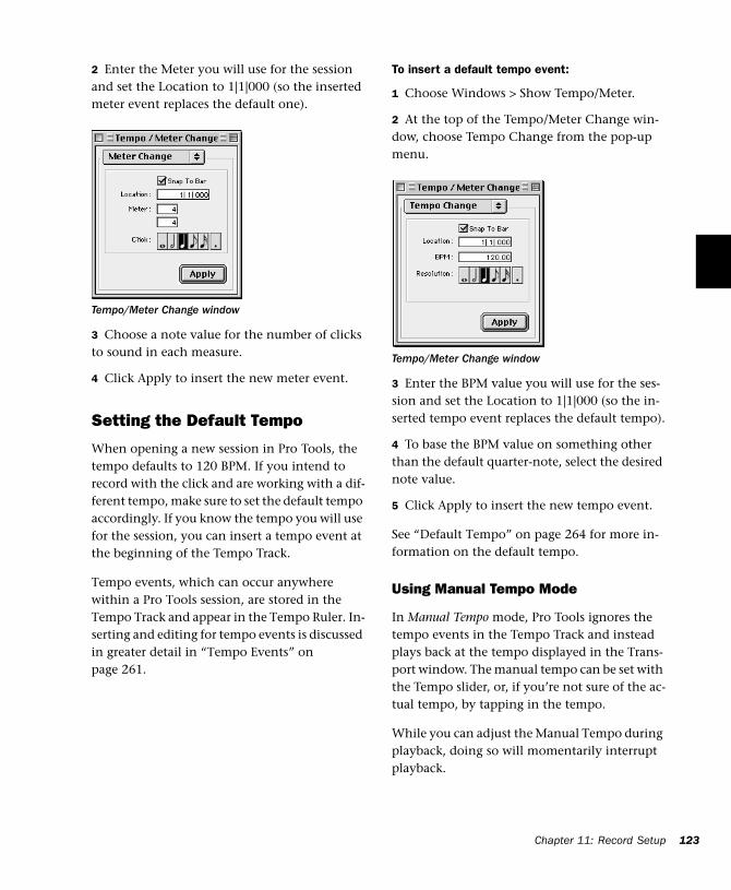
2 Enter the Meter you will use for the session and set the Location to 1|1|000 (so the inserted meter event replaces the default one).
3 Choose a note value for the number of clicks to sound in each measure.
4 Click Apply to insert the new meter event.
Setting the Default Tempo
When opening a new session in Pro Tools, the tempo defaults to 120 BPM. If you intend to record with the click and are working with a dif-ferent tempo, make sure to set the default tempo accordingly. If you know the tempo you will use for the session, you can insert a tempo event at the beginning of the Tempo Track.
Tempo events, which can occur anywhere within a Pro Tools session, are stored in the Tempo Track and appear in the Tempo Ruler. In-serting and editing for tempo events is discussed in greater detail in “Tempo Events” on page 261.
Tempo/Meter Change window
To insert a default tempo event:
1 Choose Windows > Show Tempo/Meter.
2 At the top of the Tempo/Meter Change win-dow, choose Tempo Change from the pop-up menu.
3 Enter the BPM value you will use for the ses-sion and set the Location to 1|1|000 (so the in-serted tempo event replaces the default tempo).
4 To base the BPM value on something other than the default quarter-note, select the desired note value.
5 Click Apply to insert the new tempo event.
See “Default Tempo” on page 264 for more in-formation on the default tempo.
Using Manual Tempo Mode
In Manual Tempo mode, Pro Tools ignores the tempo events in the Tempo Track and instead plays back at the tempo displayed in the Trans-port window. The manual tempo can be set with the Tempo slider, or, if you’re not sure of the ac-tual tempo, by tapping in the tempo.
While you can adjust the Manual Tempo during playback, doing so will momentarily interrupt playback.
Tempo/Meter Change window
Chapter 11: Record Setup 123
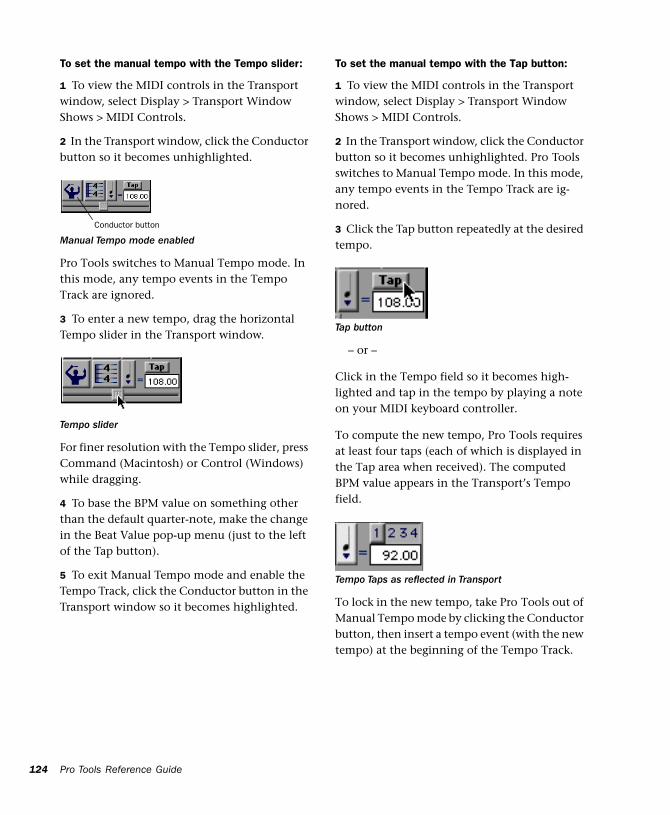
124
To set the manual tempo with the Tempo slider:
1 To view the MIDI controls in the Transport window, select Display > Transport Window Shows > MIDI Controls.
2 In the Transport window, click the Conductor button so it becomes unhighlighted.
Pro Tools switches to Manual Tempo mode. In this mode, any tempo events in the Tempo Track are ignored.
3 To enter a new tempo, drag the horizontal Tempo slider in the Transport window.
For finer resolution with the Tempo slider, press Command (Macintosh) or Control (Windows) while dragging.
4 To base the BPM value on something other than the default quarter-note, make the change in the Beat Value pop-up menu (just to the left of the Tap button).
5 To exit Manual Tempo mode and enable the Tempo Track, click the Conductor button in the Transport window so it becomes highlighted.
Manual Tempo mode enabled
Tempo slider
Conductor button
Pro Tools Reference Guide
To set the manual tempo with the Tap button:
1 To view the MIDI controls in the Transport window, select Display > Transport Window Shows > MIDI Controls.
2 In the Transport window, click the Conductor button so it becomes unhighlighted. Pro Tools switches to Manual Tempo mode. In this mode, any tempo events in the Tempo Track are ig-nored.
3 Click the Tap button repeatedly at the desired tempo.
– or –
Click in the Tempo field so it becomes high-lighted and tap in the tempo by playing a note on your MIDI keyboard controller.
To compute the new tempo, Pro Tools requires at least four taps (each of which is displayed in the Tap area when received). The computed BPM value appears in the Transport’s Tempo field.
To lock in the new tempo, take Pro Tools out of Manual Tempo mode by clicking the Conductor button, then insert a tempo event (with the new tempo) at the beginning of the Tempo Track.
Tap button
Tempo Taps as reflected in Transport
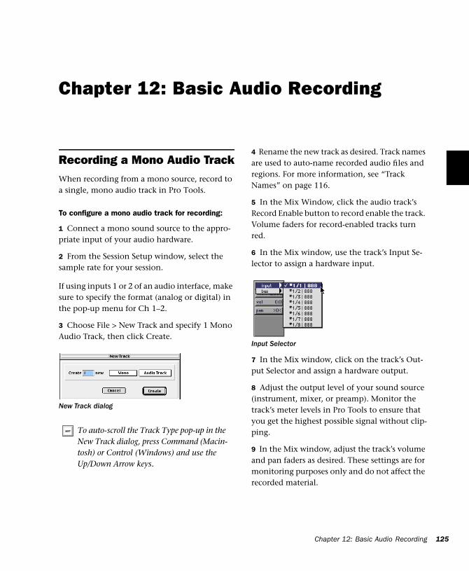
Chapter 12: Basic Audio Recording
Recording a Mono Audio TrackWhen recording from a mono source, record to a single, mono audio track in Pro Tools.
To configure a mono audio track for recording:
1 Connect a mono sound source to the appro-priate input of your audio hardware.
2 From the Session Setup window, select the sample rate for your session.
If using inputs 1 or 2 of an audio interface, make sure to specify the format (analog or digital) in the pop-up menu for Ch 1–2.
3 Choose File > New Track and specify 1 Mono Audio Track, then click Create.
New Track dialog
To auto-scroll the Track Type pop-up in the New Track dialog, press Command (Macin-tosh) or Control (Windows) and use the Up/Down Arrow keys.
4 Rename the new track as desired. Track names are used to auto-name recorded audio files and regions. For more information, see “Track Names” on page 116.
5 In the Mix Window, click the audio track’s Record Enable button to record enable the track. Volume faders for record-enabled tracks turn red.
6 In the Mix window, use the track’s Input Se-lector to assign a hardware input.
7 In the Mix window, click on the track’s Out-put Selector and assign a hardware output.
8 Adjust the output level of your sound source (instrument, mixer, or preamp). Monitor the track’s meter levels in Pro Tools to ensure that you get the highest possible signal without clip-ping.
9 In the Mix window, adjust the track’s volume and pan faders as desired. These settings are for monitoring purposes only and do not affect the recorded material.
Input Selector
Chapter 12: Basic Audio Recording 125
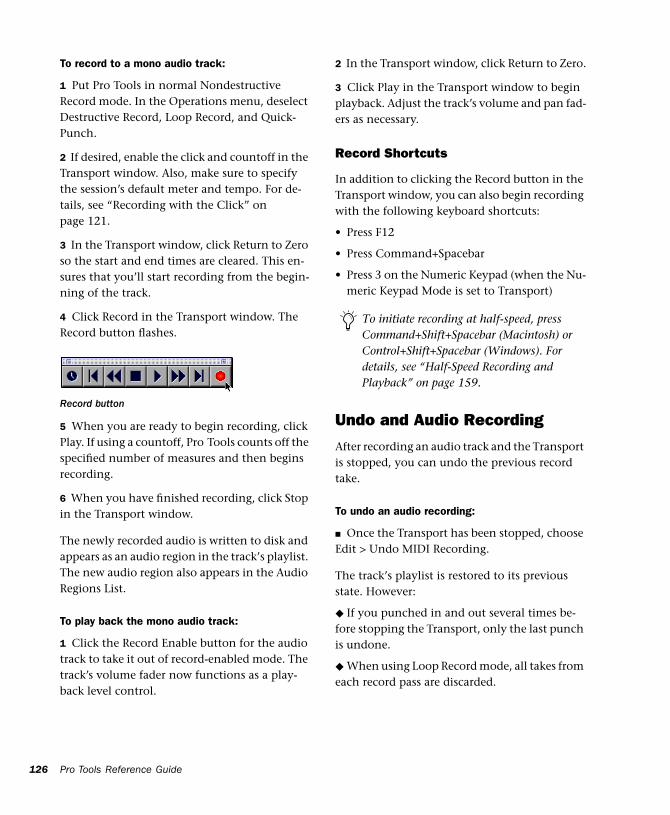
126
To record to a mono audio track:
1 Put Pro Tools in normal Nondestructive Record mode. In the Operations menu, deselect Destructive Record, Loop Record, and Quick-Punch.
2 If desired, enable the click and countoff in the Transport window. Also, make sure to specify the session’s default meter and tempo. For de-tails, see “Recording with the Click” on page 121.
3 In the Transport window, click Return to Zero so the start and end times are cleared. This en-sures that you’ll start recording from the begin-ning of the track.
4 Click Record in the Transport window. The Record button flashes.
5 When you are ready to begin recording, click Play. If using a countoff, Pro Tools counts off the specified number of measures and then begins recording.
6 When you have finished recording, click Stop in the Transport window.
The newly recorded audio is written to disk and appears as an audio region in the track’s playlist. The new audio region also appears in the Audio Regions List.
To play back the mono audio track:
1 Click the Record Enable button for the audio track to take it out of record-enabled mode. The track’s volume fader now functions as a play-back level control.
Record button
Pro Tools Reference Guide
2 In the Transport window, click Return to Zero.
3 Click Play in the Transport window to begin playback. Adjust the track’s volume and pan fad-ers as necessary.
Record Shortcuts
In addition to clicking the Record button in the Transport window, you can also begin recording with the following keyboard shortcuts:
• Press F12
• Press Command+Spacebar
• Press 3 on the Numeric Keypad (when the Nu-meric Keypad Mode is set to Transport)
Undo and Audio Recording
After recording an audio track and the Transport is stopped, you can undo the previous record take.
To undo an audio recording:
■ Once the Transport has been stopped, choose Edit > Undo MIDI Recording.
The track’s playlist is restored to its previous state. However:
◆ If you punched in and out several times be-fore stopping the Transport, only the last punch is undone.
◆ When using Loop Record mode, all takes from each record pass are discarded.
To initiate recording at half-speed, press Command+Shift+Spacebar (Macintosh) or Control+Shift+Spacebar (Windows). For details, see “Half-Speed Recording and Playback” on page 159.
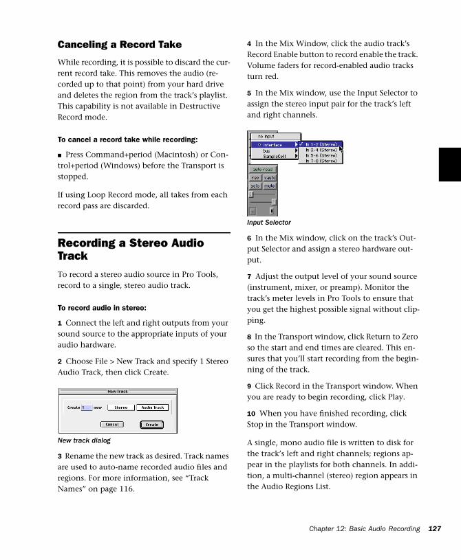
Canceling a Record Take
While recording, it is possible to discard the cur-rent record take. This removes the audio (re-corded up to that point) from your hard drive and deletes the region from the track’s playlist. This capability is not available in Destructive Record mode.
To cancel a record take while recording:
■ Press Command+period (Macintosh) or Con-trol+period (Windows) before the Transport is stopped.
If using Loop Record mode, all takes from each record pass are discarded.
Recording a Stereo Audio TrackTo record a stereo audio source in Pro Tools, record to a single, stereo audio track.
To record audio in stereo:
1 Connect the left and right outputs from your sound source to the appropriate inputs of your audio hardware.
2 Choose File > New Track and specify 1 Stereo Audio Track, then click Create.
3 Rename the new track as desired. Track names are used to auto-name recorded audio files and regions. For more information, see “Track Names” on page 116.
New track dialog
4 In the Mix Window, click the audio track’s Record Enable button to record enable the track. Volume faders for record-enabled audio tracks turn red.
5 In the Mix window, use the Input Selector to assign the stereo input pair for the track’s left and right channels.
6 In the Mix window, click on the track’s Out-put Selector and assign a stereo hardware out-put.
7 Adjust the output level of your sound source (instrument, mixer, or preamp). Monitor the track’s meter levels in Pro Tools to ensure that you get the highest possible signal without clip-ping.
8 In the Transport window, click Return to Zero so the start and end times are cleared. This en-sures that you’ll start recording from the begin-ning of the track.
9 Click Record in the Transport window. When you are ready to begin recording, click Play.
10 When you have finished recording, click Stop in the Transport window.
A single, mono audio file is written to disk for the track’s left and right channels; regions ap-pear in the playlists for both channels. In addi-tion, a multi-channel (stereo) region appears in the Audio Regions List.
Input Selector
Chapter 12: Basic Audio Recording 127
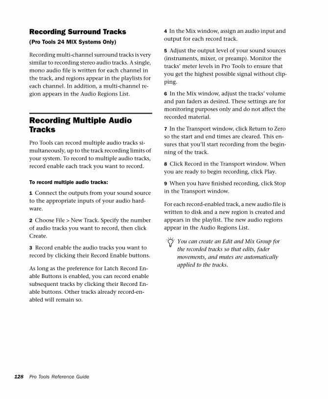
128
Recording Surround Tracks(Pro Tools 24 MIX Systems Only)
Recording multi-channel surround tracks is very similar to recording stereo audio tracks. A single, mono audio file is written for each channel in the track, and regions appear in the playlists for each channel. In addition, a multi-channel re-gion appears in the Audio Regions List.
Recording Multiple Audio TracksPro Tools can record multiple audio tracks si-multaneously, up to the track recording limits of your system. To record to multiple audio tracks, record enable each track you want to record.
To record multiple audio tracks:
1 Connect the outputs from your sound source to the appropriate inputs of your audio hard-ware.
2 Choose File > New Track. Specify the number of audio tracks you want to record, then click Create.
3 Record enable the audio tracks you want to record by clicking their Record Enable buttons.
As long as the preference for Latch Record En-able Buttons is enabled, you can record enable subsequent tracks by clicking their Record En-able buttons. Other tracks already record-en-abled will remain so.
Pro Tools Reference Guide
4 In the Mix window, assign an audio input and output for each record track.
5 Adjust the output level of your sound sources (instruments, mixer, or preamp). Monitor the tracks’ meter levels in Pro Tools to ensure that you get the highest possible signal without clip-ping.
6 In the Mix window, adjust the tracks’ volume and pan faders as desired. These settings are for monitoring purposes only and do not affect the recorded material.
7 In the Transport window, click Return to Zero so the start and end times are cleared. This en-sures that you’ll start recording from the begin-ning of the track.
8 Click Record in the Transport window. When you are ready to begin recording, click Play.
9 When you have finished recording, click Stop in the Transport window.
For each record-enabled track, a new audio file is written to disk and a new region is created and appears in the playlist. The new audio regions appear in the Audio Regions List.
You can create an Edit and Mix Group for the recorded tracks so that edits, fader movements, and mutes are automatically applied to the tracks.
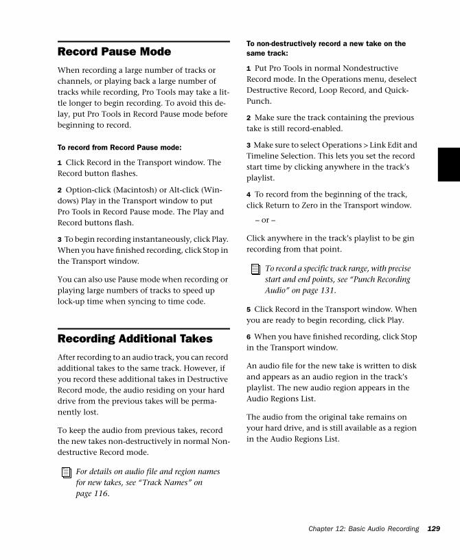
Record Pause ModeWhen recording a large number of tracks or channels, or playing back a large number of tracks while recording, Pro Tools may take a lit-tle longer to begin recording. To avoid this de-lay, put Pro Tools in Record Pause mode before beginning to record.
To record from Record Pause mode:
1 Click Record in the Transport window. The Record button flashes.
2 Option-click (Macintosh) or Alt-click (Win-dows) Play in the Transport window to put Pro Tools in Record Pause mode. The Play and Record buttons flash.
3 To begin recording instantaneously, click Play. When you have finished recording, click Stop in the Transport window.
You can also use Pause mode when recording or playing large numbers of tracks to speed up lock-up time when syncing to time code.
Recording Additional TakesAfter recording to an audio track, you can record additional takes to the same track. However, if you record these additional takes in Destructive Record mode, the audio residing on your hard drive from the previous takes will be perma-nently lost.
To keep the audio from previous takes, record the new takes non-destructively in normal Non-destructive Record mode.
For details on audio file and region names for new takes, see “Track Names” on page 116.
To non-destructively record a new take on the same track:
1 Put Pro Tools in normal Nondestructive Record mode. In the Operations menu, deselect Destructive Record, Loop Record, and Quick-Punch.
2 Make sure the track containing the previous take is still record-enabled.
3 Make sure to select Operations > Link Edit and Timeline Selection. This lets you set the record start time by clicking anywhere in the track’s playlist.
4 To record from the beginning of the track, click Return to Zero in the Transport window.
– or –
Click anywhere in the track’s playlist to be gin recording from that point.
5 Click Record in the Transport window. When you are ready to begin recording, click Play.
6 When you have finished recording, click Stop in the Transport window.
An audio file for the new take is written to disk and appears as an audio region in the track’s playlist. The new audio region appears in the Audio Regions List.
The audio from the original take remains on your hard drive, and is still available as a region in the Audio Regions List.
To record a specific track range, with precise start and end points, see “Punch Recording Audio” on page 131.
Chapter 12: Basic Audio Recording 129
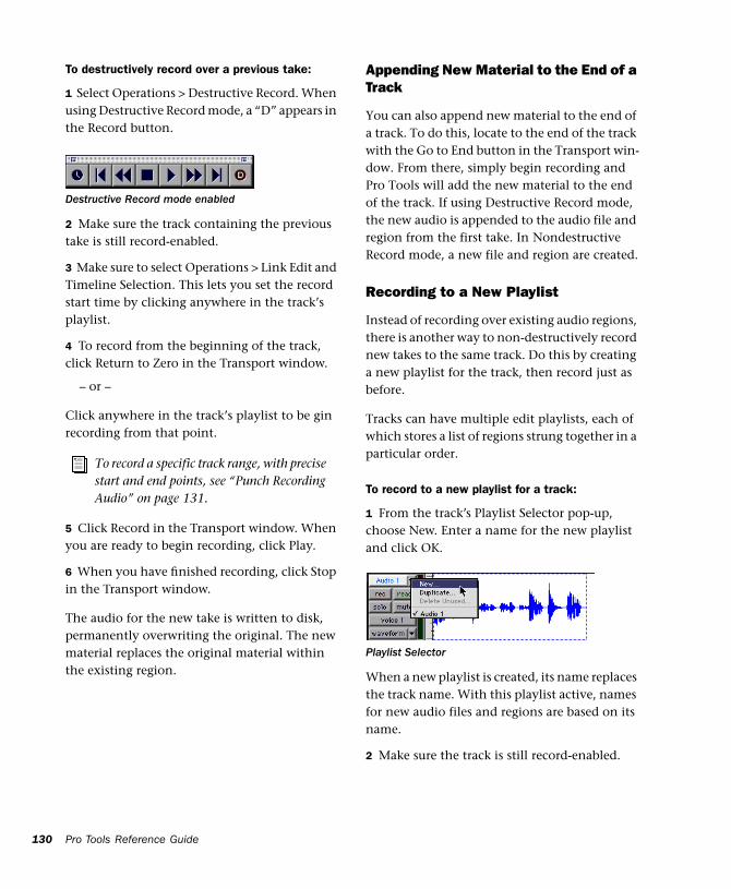
130
To destructively record over a previous take:
1 Select Operations > Destructive Record. When using Destructive Record mode, a “D” appears in the Record button.
2 Make sure the track containing the previous take is still record-enabled.
3 Make sure to select Operations > Link Edit and Timeline Selection. This lets you set the record start time by clicking anywhere in the track’s playlist.
4 To record from the beginning of the track, click Return to Zero in the Transport window.
– or –
Click anywhere in the track’s playlist to be gin recording from that point.
5 Click Record in the Transport window. When you are ready to begin recording, click Play.
6 When you have finished recording, click Stop in the Transport window.
The audio for the new take is written to disk, permanently overwriting the original. The new material replaces the original material within the existing region.
Destructive Record mode enabled
To record a specific track range, with precise start and end points, see “Punch Recording Audio” on page 131.
Pro Tools Reference Guide
Appending New Material to the End of a Track
You can also append new material to the end of a track. To do this, locate to the end of the track with the Go to End button in the Transport win-dow. From there, simply begin recording and Pro Tools will add the new material to the end of the track. If using Destructive Record mode, the new audio is appended to the audio file and region from the first take. In Nondestructive Record mode, a new file and region are created.
Recording to a New Playlist
Instead of recording over existing audio regions, there is another way to non-destructively record new takes to the same track. Do this by creating a new playlist for the track, then record just as before.
Tracks can have multiple edit playlists, each of which stores a list of regions strung together in a particular order.
To record to a new playlist for a track:
1 From the track’s Playlist Selector pop-up, choose New. Enter a name for the new playlist and click OK.
When a new playlist is created, its name replaces the track name. With this playlist active, names for new audio files and regions are based on its name.
2 Make sure the track is still record-enabled.
Playlist Selector
3 In the Transport window, click Return to Zero.
4 Click Record in the Transport window. When you are ready to begin recording, click Play.
5 When you have finished recording, click Stop in the Transport window.
An audio file for the new take is written to disk and appears as an audio region in the track’s playlist. The new audio region appears in the Audio Regions List.
6 To audition the new take, click Play in the Transport window.
7 To go back to a previous playlist to compare it to the new take, select the playlist from the track’s Playlist Selector.
Selecting a playlist recalls its regions as they pre-viously appeared in the track. At any time, all re-gions from all playlists are available in the Re-gions List, and can be mixed and matched between playlists and tracks.
For more information on playlists and playlist editing, see “Playlists” on page 172.
Punch Recording AudioTo replace a portion of a recorded track, you can punch in by specifying the record range before recording.
Though there are several ways to set record and play ranges (see “Setting Punch/Loop Points” on page 135), perhaps the easiest is to select within the track’s playlist the material to be replaced.
NOTE: To set a record or play range by selecting within a playlist, the Edit and Timeline selections must be linked.
You can listen to track material up to and after the punch record range by enabling pre-and post-roll. Listening to pre-roll is helpful in get-ting the feel for playing in the new material.
During the recording process, playback begins at the pre-roll time (if enabled) and proceeds to the start time (the punch-in point), where re-cording begin. When the end time (the punch-out point) is reached, Pro Tools automatically switches out of record mode and continues play-ing through the specified amount of post-roll. This automated punch-in/out feature is a pow-erful and precise way of re-recording a portion of a track.
NOTE: If you are recording in normal Nondestruc-tive Record mode, punches do not permanently re-place the source material. If you actually want to write over the previous data, erasing it forever, use Destructive Record mode.
Monitoring during Punch-Ins
When punch recording, you may want to en-able Auto Input Monitoring (by selecting it in the Operations menu). For details, see “Auto In-put Monitoring” on page 113.
To punch record on an audio track:
1 To record non-destructively, make sure that Operations > Destructive Record is not selected.
If you do want to permanently record over the punched record range, select Operations > De-structive Record.
2 Make sure the track containing the previous take is still record-enabled.
3 Make sure to select Operations > Link Edit and Timeline Selection.
Chapter 12: Basic Audio Recording 131
132
4 With the Selector, drag in the track’s playlist until the selection encompasses the desired punch range.
For other methods of setting the record range, see “Setting Punch/Loop Points” on page 135.
5 To hear existing track material up to the start point, or after the end point, enable and set pre/post-roll times. For details, see “Setting Pre/Post-Roll” on page 137.
6 Click Record in the Transport window. When you are ready to begin recording, click Play.
If pre-roll is enabled, the track material leading up to the punch-in point plays. You can start playing during the pre-roll to get the “feel.” Ma-terial is not recorded until the start point is reached.
When the start point is reached, Pro Tools be-gins recording. Recording continues until the end point is reached, unless Stop is clicked in the Transport window. If post-roll is enabled, playback continues for the specified post-roll amount.
If recording non-destructively, a new audio file is written to your hard drive and a new audio re-gion appears in the record track and Audio Re-gions List.
If recording in Destructive Record mode, the new audio overwrites the previous material in the existing audio file and region.
Pro Tools Reference Guide
Loop Recording AudioPro Tools provides a loop recording feature that allows you to record take after take while the same section of audio repeats over and over. This is a convenient technique for quickly re-cording multiple takes of a part without losing spontaneity.
When loop recording, you must first specify the start and end points for the loop. Though there are several ways to set record and play ranges (see “Setting Punch/Loop Points” on page 135), perhaps the easiest is to select within the track’s playlist the material to be looped.
NOTE: To set a record or play range by selecting within a playlist, the Edit and Timeline selections must be linked.
The pre-roll setting, if enabled, is used during the first record pass, but on each successive loop, the pre- and post-roll times are ignored. To compensate for this, you may want to make the loop range slightly longer. Later, you can trim back the recorded takes to the desired length with the Trimmer tool (see “The Trimmer Tool” on page 215).
When loop recording audio, Pro Tools creates a single audio file that comprises all takes. Takes appear as individual regions in the Audio Re-gions List and are numbered sequentially. Once you stop recording, you can audition any of the recorded takes.
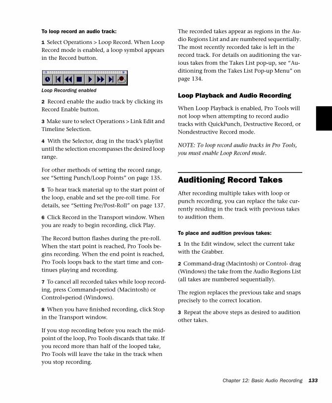
To loop record an audio track:
1 Select Operations > Loop Record. When Loop Record mode is enabled, a loop symbol appears in the Record button.
2 Record enable the audio track by clicking its Record Enable button.
3 Make sure to select Operations > Link Edit and Timeline Selection.
4 With the Selector, drag in the track’s playlist until the selection encompasses the desired loop range.
For other methods of setting the record range, see “Setting Punch/Loop Points” on page 135.
5 To hear track material up to the start point of the loop, enable and set the pre-roll time. For details, see “Setting Pre/Post-Roll” on page 137.
6 Click Record in the Transport window. When you are ready to begin recording, click Play.
The Record button flashes during the pre-roll. When the start point is reached, Pro Tools be-gins recording. When the end point is reached, Pro Tools loops back to the start time and con-tinues playing and recording.
7 To cancel all recorded takes while loop record-ing, press Command+period (Macintosh) or Control+period (Windows).
8 When you have finished recording, click Stop in the Transport window.
If you stop recording before you reach the mid-point of the loop, Pro Tools discards that take. If you record more than half of the looped take, Pro Tools will leave the take in the track when you stop recording.
Loop Recording enabled
The recorded takes appear as regions in the Au-dio Regions List and are numbered sequentially. The most recently recorded take is left in the record track. For details on auditioning the var-ious takes from the Takes List pop-up, see “Au-ditioning from the Takes List Pop-up Menu” on page 134.
Loop Playback and Audio Recording
When Loop Playback is enabled, Pro Tools will not loop when attempting to record audio tracks with QuickPunch, Destructive Record, or Nondestructive Record mode.
NOTE: To loop record audio tracks in Pro Tools, you must enable Loop Record mode.
Auditioning Record TakesAfter recording multiple takes with loop or punch recording, you can replace the take cur-rently residing in the track with previous takes to audition them.
To place and audition previous takes:
1 In the Edit window, select the current take with the Grabber.
2 Command-drag (Macintosh) or Control- drag (Windows) the take from the Audio Regions List (all takes are numbered sequentially).
The region replaces the previous take and snaps precisely to the correct location.
3 Repeat the above steps as desired to audition other takes.
Chapter 12: Basic Audio Recording 133
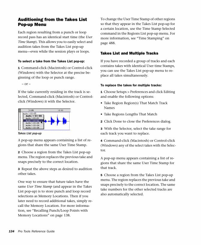
134
Auditioning from the Takes List Pop-up Menu
Each region resulting from a punch or loop record pass has an identical start time (the User Time Stamp). This allows you to easily select and audition takes from the Takes List pop-up menu—even while the session plays or loops.
To select a take from the Takes List pop-up:
1 Command-click (Macintosh) or Control-click (Windows) with the Selector at the precise be-ginning of the loop or punch range.
– or –
If the take currently residing in the track is se-lected, Command-click (Macintosh) or Control-click (Windows) it with the Selector.
A pop-up menu appears containing a list of re-gions that share the same User Time Stamp.
2 Choose a region from the Takes List pop-up menu. The region replaces the previous take and snaps precisely to the correct location.
3 Repeat the above steps as desired to audition other takes.
One way to ensure that future takes have the same User Time Stamp (and appear in the Takes List pop-up) is to store punch and loop record selections as Memory Locations. Then if you later need to record additional takes, simply re-call the Memory Location. For more informa-tion, see “Recalling Punch/Loop Points with Memory Locations” on page 138.
Takes List pop-up
Pro Tools Reference Guide
To change the User Time Stamp of other regions so that they appear in the Takes List pop-up for a certain location, use the Time Stamp Selected command in the Regions List pop-up menu. For more information, see “Time Stamping” on page 488.
Takes List and Multiple Tracks
If you have recorded a group of tracks and each contains takes with identical User time Stamps, you can use the Takes List pop-up menu to re-place all takes simultaneously.
To replace the takes for multiple tracks:
1 Choose Setups > Preferences and click Editing and enable the following options:
• Take Region Region(s) That Match Track Names
• Take Regions Lengths That Match
2 Click Done to close the Preferences dialog.
3 With the Selector, select the take range for each track you want to replace.
4 Command-click (Macintosh) or Control-click (Windows) any of the select takes with the Selec-tor.
A pop-up menu appears containing a list of re-gions that share the same User Time Stamp for that track.
5 Choose a region from the Takes List pop-up menu. The region replaces the previous take and snaps precisely to the correct location. The same take numbers for the other selected tracks are also automatically selected.
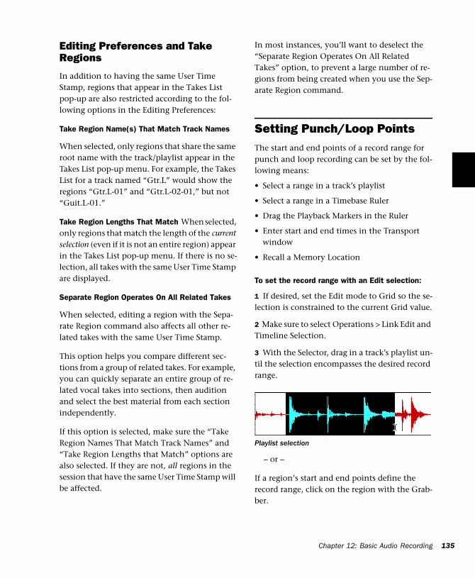
Editing Preferences and Take Regions
In addition to having the same User Time Stamp, regions that appear in the Takes List pop-up are also restricted according to the fol-lowing options in the Editing Preferences:
Take Region Name(s) That Match Track Names
When selected, only regions that share the same root name with the track/playlist appear in the Takes List pop-up menu. For example, the Takes List for a track named “Gtr.L” would show the regions “Gtr.L-01” and “Gtr.L-02-01,” but not “Guit.L-01.”
Take Region Lengths That Match When selected, only regions that match the length of the current selection (even if it is not an entire region) appear in the Takes List pop-up menu. If there is no se-lection, all takes with the same User Time Stamp are displayed.
Separate Region Operates On All Related Takes
When selected, editing a region with the Sepa-rate Region command also affects all other re-lated takes with the same User Time Stamp.
This option helps you compare different sec-tions from a group of related takes. For example, you can quickly separate an entire group of re-lated vocal takes into sections, then audition and select the best material from each section independently.
If this option is selected, make sure the “Take Region Names That Match Track Names” and “Take Region Lengths that Match” options are also selected. If they are not, all regions in the session that have the same User Time Stamp will be affected.
In most instances, you’ll want to deselect the “Separate Region Operates On All Related Takes” option, to prevent a large number of re-gions from being created when you use the Sep-arate Region command.
Setting Punch/Loop PointsThe start and end points of a record range for punch and loop recording can be set by the fol-lowing means:
• Select a range in a track’s playlist
• Select a range in a Timebase Ruler
• Drag the Playback Markers in the Ruler
• Enter start and end times in the Transport window
• Recall a Memory Location
To set the record range with an Edit selection:
1 If desired, set the Edit mode to Grid so the se-lection is constrained to the current Grid value.
2 Make sure to select Operations > Link Edit and Timeline Selection.
3 With the Selector, drag in a track’s playlist un-til the selection encompasses the desired record range.
– or –
If a region’s start and end points define the record range, click on the region with the Grab-ber.
Playlist selection
Chapter 12: Basic Audio Recording 135
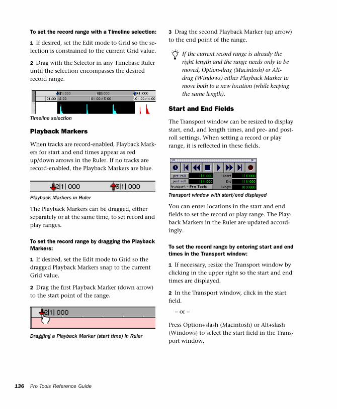
136
To set the record range with a Timeline selection:
1 If desired, set the Edit mode to Grid so the se-lection is constrained to the current Grid value.
2 Drag with the Selector in any Timebase Ruler until the selection encompasses the desired record range.
Playback Markers
When tracks are record-enabled, Playback Mark-ers for start and end times appear as red up/down arrows in the Ruler. If no tracks are record-enabled, the Playback Markers are blue.
The Playback Markers can be dragged, either separately or at the same time, to set record and play ranges.
To set the record range by dragging the Playback Markers:
1 If desired, set the Edit mode to Grid so the dragged Playback Markers snap to the current Grid value.
2 Drag the first Playback Marker (down arrow) to the start point of the range.
Timeline selection
Playback Markers in Ruler
Dragging a Playback Marker (start time) in Ruler
Pro Tools Reference Guide
3 Drag the second Playback Marker (up arrow) to the end point of the range.
Start and End Fields
The Transport window can be resized to display start, end, and length times, and pre- and post-roll settings. When setting a record or play range, it is reflected in these fields.
You can enter locations in the start and end fields to set the record or play range. The Play-back Markers in the Ruler are updated accord-ingly.
To set the record range by entering start and end times in the Transport window:
1 If necessary, resize the Transport window by clicking in the upper right so the start and end times are displayed.
2 In the Transport window, click in the start field.
– or –
Press Option+slash (Macintosh) or Alt+slash (Windows) to select the start field in the Trans-port window.
If the current record range is already the right length and the range needs only to be moved, Option-drag (Macintosh) or Alt-drag (Windows) either Playback Marker to move both to a new location (while keeping the same length).
Transport window with start/end displayed
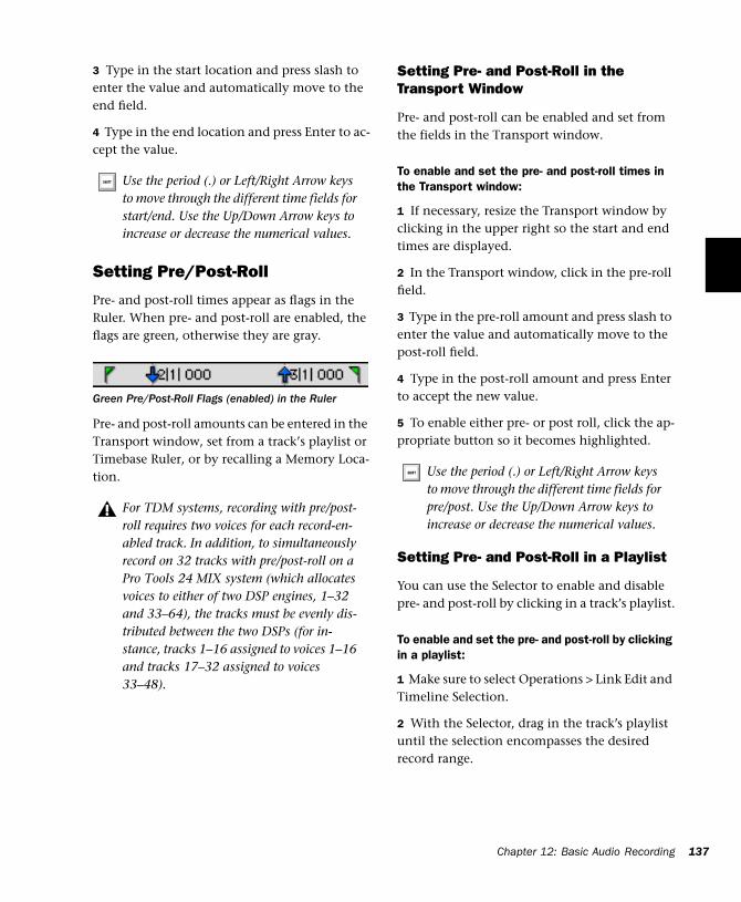
3 Type in the start location and press slash to enter the value and automatically move to the end field.
4 Type in the end location and press Enter to ac-cept the value.
Setting Pre/Post-Roll
Pre- and post-roll times appear as flags in the Ruler. When pre- and post-roll are enabled, the flags are green, otherwise they are gray.
Pre- and post-roll amounts can be entered in the Transport window, set from a track’s playlist or Timebase Ruler, or by recalling a Memory Loca-tion.
Use the period (.) or Left/Right Arrow keys to move through the different time fields for start/end. Use the Up/Down Arrow keys to increase or decrease the numerical values.
Green Pre/Post-Roll Flags (enabled) in the Ruler
For TDM systems, recording with pre/post-roll requires two voices for each record-en-abled track. In addition, to simultaneously record on 32 tracks with pre/post-roll on a Pro Tools 24 MIX system (which allocates voices to either of two DSP engines, 1–32 and 33–64), the tracks must be evenly dis-tributed between the two DSPs (for in-stance, tracks 1–16 assigned to voices 1–16 and tracks 17–32 assigned to voices 33–48).
Setting Pre- and Post-Roll in the Transport Window
Pre- and post-roll can be enabled and set from the fields in the Transport window.
To enable and set the pre- and post-roll times in the Transport window:
1 If necessary, resize the Transport window by clicking in the upper right so the start and end times are displayed.
2 In the Transport window, click in the pre-roll field.
3 Type in the pre-roll amount and press slash to enter the value and automatically move to the post-roll field.
4 Type in the post-roll amount and press Enter to accept the new value.
5 To enable either pre- or post roll, click the ap-propriate button so it becomes highlighted.
Setting Pre- and Post-Roll in a Playlist
You can use the Selector to enable and disable pre- and post-roll by clicking in a track’s playlist.
To enable and set the pre- and post-roll by clicking in a playlist:
1 Make sure to select Operations > Link Edit and Timeline Selection.
2 With the Selector, drag in the track’s playlist until the selection encompasses the desired record range.
Use the period (.) or Left/Right Arrow keys to move through the different time fields for pre/post. Use the Up/Down Arrow keys to increase or decrease the numerical values.
Chapter 12: Basic Audio Recording 137
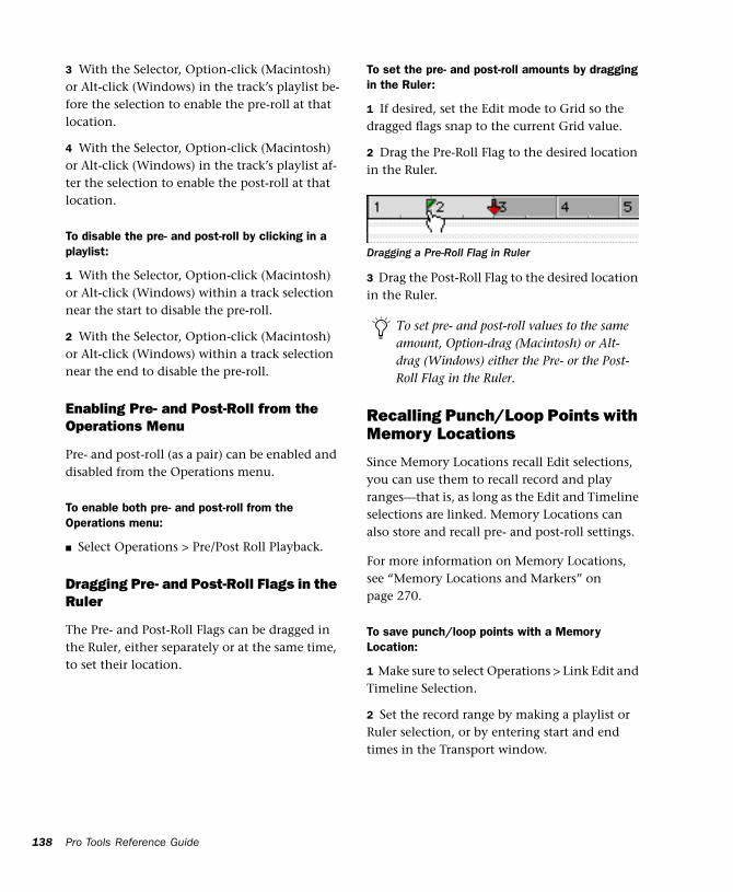
138
3 With the Selector, Option-click (Macintosh) or Alt-click (Windows) in the track’s playlist be-fore the selection to enable the pre-roll at that location.
4 With the Selector, Option-click (Macintosh) or Alt-click (Windows) in the track’s playlist af-ter the selection to enable the post-roll at that location.
To disable the pre- and post-roll by clicking in a playlist:
1 With the Selector, Option-click (Macintosh) or Alt-click (Windows) within a track selection near the start to disable the pre-roll.
2 With the Selector, Option-click (Macintosh) or Alt-click (Windows) within a track selection near the end to disable the pre-roll.
Enabling Pre- and Post-Roll from the Operations Menu
Pre- and post-roll (as a pair) can be enabled and disabled from the Operations menu.
To enable both pre- and post-roll from the Operations menu:
■ Select Operations > Pre/Post Roll Playback.
Dragging Pre- and Post-Roll Flags in the Ruler
The Pre- and Post-Roll Flags can be dragged in the Ruler, either separately or at the same time, to set their location.
Pro Tools Reference Guide
To set the pre- and post-roll amounts by dragging in the Ruler:
1 If desired, set the Edit mode to Grid so the dragged flags snap to the current Grid value.
2 Drag the Pre-Roll Flag to the desired location in the Ruler.
3 Drag the Post-Roll Flag to the desired location in the Ruler.
Recalling Punch/Loop Points with Memory Locations
Since Memory Locations recall Edit selections, you can use them to recall record and play ranges—that is, as long as the Edit and Timeline selections are linked. Memory Locations can also store and recall pre- and post-roll settings.
For more information on Memory Locations, see “Memory Locations and Markers” on page 270.
To save punch/loop points with a Memory Location:
1 Make sure to select Operations > Link Edit and Timeline Selection.
2 Set the record range by making a playlist or Ruler selection, or by entering start and end times in the Transport window.
Dragging a Pre-Roll Flag in Ruler
To set pre- and post-roll values to the same amount, Option-drag (Macintosh) or Alt-drag (Windows) either the Pre- or the Post-Roll Flag in the Ruler.
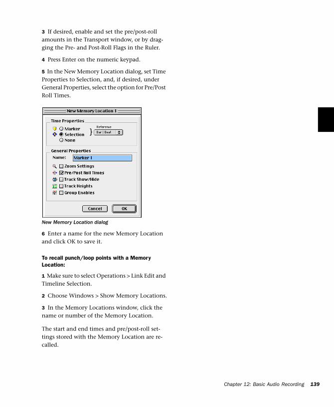
3 If desired, enable and set the pre/post-roll amounts in the Transport window, or by drag-ging the Pre- and Post-Roll Flags in the Ruler.
4 Press Enter on the numeric keypad.
5 In the New Memory Location dialog, set Time Properties to Selection, and, if desired, under General Properties, select the option for Pre/Post Roll Times.
6 Enter a name for the new Memory Location and click OK to save it.
To recall punch/loop points with a Memory Location:
1 Make sure to select Operations > Link Edit and Timeline Selection.
2 Choose Windows > Show Memory Locations.
3 In the Memory Locations window, click the name or number of the Memory Location.
The start and end times and pre/post-roll set-tings stored with the Memory Location are re-called.
New Memory Location dialog
Chapter 12: Basic Audio Recording 139

140
Pro Tools Reference Guide
Chapter 13: MIDI Recording
Although recording MIDI in Pro Tools is similar to recording audio, there are some important differences.
◆ Unlike audio, MIDI recording is almost always destructive. See “The Record Modes and MIDI” on page 120 for details.
◆ Unlike audio, a MIDI recording take can be undone after stopping the Transport. For details, see “Undo and MIDI Recording” on page 147.
◆ Unlike audio tracks, MIDI tracks can be record enabled on the fly while recording.
◆ Similar to audio tracks, MIDI tracks have an Input Selector that determines which channels are routed and recorded to the track. If the Input Selector is set to All, all channels for all devices are routed to the track.
◆ It is not necessary to use QuickPunch to punch in on the fly with MIDI tracks. This capa-bility is available in normal Nondestructive Record Mode, and in Destructive Record mode.
Refer to the “Pro Tools Installation Guide” that came with your system for details on configuration for MIDI recording.
Recording from MIDI DevicesThe MIDI Inputs for record-enabled MIDI tracks determine which MIDI data is recorded in Pro Tools. MIDI Inputs can be set to a specific device and channel, or they can be set to “All,” where all channels for all devices are merged to the track.
MIDI tracks in Pro Tools do not contain multi-ple channels and always play back on the track’s assigned device and channels. Multiple MIDI channels can be simultaneously recorded to multiple tracks.
The following Pro Tools options determine whether you can record from a MIDI controller device:
◆ Devices that are assigned as a MIDI Controller in the Peripherals dialog are ignored when MIDI tracks are recorded. This is to avoid recording data from MIDI control surfaces like the Mackie HUI.
◆ On the Macintosh, only devices that are en-abled in the Input Devices dialog can be re-corded from. For more information, see “Enabling Input Devices” on page 142.
Chapter 13: MIDI Recording 141
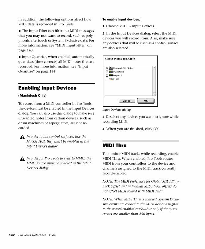
142
In addition, the following options affect how MIDI data is recorded in Pro Tools.
◆ The Input Filter can filter out MIDI messages that you may not want to record, such as poly-phonic aftertouch or System Exclusive data. For more information, see “MIDI Input Filter” on page 143.
◆ Input Quantize, when enabled, automatically quantizes (time corrects) all MIDI notes that are recorded. For more information, see “Input Quantize” on page 144.
Enabling Input Devices(Macintosh Only)
To record from a MIDI controller in Pro Tools, the device must be enabled in the Input Devices dialog. You can also use this dialog to make sure unwanted notes from certain devices, such as drum machines or arpeggiators, are not re-corded.
In order to use control surfaces, like the Mackie HUI, they must be enabled in the Input Devices dialog.
In order for Pro Tools to sync to MMC, the MMC source must be enabled in the Input Devices dialog.
Pro Tools Reference Guide
To enable input devices:
1 Choose MIDI > Input Devices.
2 In the Input Devices dialog, select the MIDI devices you will record from. Also, make sure any devices that will be used as a control surface are also selected.
3 Deselect any devices you want to ignore while recording MIDI.
4 When you are finished, click OK.
MIDI ThruTo monitor MIDI tracks while recording, enable MIDI Thru. When enabled, Pro Tools routes MIDI from your controllers to the device and channels assigned to the MIDI track currently record-enabled.
NOTE: The MIDI Preference for Global MIDI Play-back Offset and individual MIDI track offsets do not affect MIDI routed with MIDI Thru.
NOTE: When MIDI Thru is enabled, System Exclu-sive events are echoed to the MIDI device assigned to the record-enabled track—but only if the sysex events are smaller than 256 bytes.
Input Devices dialog
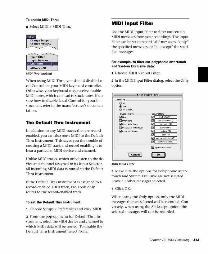
To enable MIDI Thru:
■ Select MIDI > MIDI Thru.
When using MIDI Thru, you should disable Lo-cal Control on your MIDI keyboard controller. Otherwise, your keyboard may receive double MIDI notes, which can lead to stuck notes. If un-sure how to disable Local Control for your in-strument, refer to the manufacturer’s documen-tation.
The Default Thru Instrument
In addition to any MIDI tracks that are record-enabled, you can also route MIDI to the Default Thru Instrument. This saves you the trouble of creating a MIDI track and record enabling it to hear a particular MIDI device and channel.
Unlike MIDI tracks, which only listen to the de-vice and channel assigned to its Input Selector, all incoming MIDI data is routed to the Default Thru Instrument.
If the Default Thru Instrument is assigned to a record-enabled MIDI track, Pro Tools only routes to the record-enabled track.
To set the Default Thru Instrument:
1 Choose Setups > Preferences and click MIDI.
2 From the pop-up menu for Default Thru In-strument, select the MIDI device and channel to which MIDI data will be routed. To disable the Default Thru Instrument, select None.
MIDI Thru enabled
MIDI Input FilterUse the MIDI Input Filter to filter out certain MIDI messages from your recordings. The Input Filter can be set to record “all” messages, “only” the specified messages, or “all except” the speci-fied messages.
For example, to filter out polyphonic aftertouch and System Exclusive data:
1 Choose MIDI > Input Filter.
2 In the MIDI Input Filter dialog, select the Only option.
3 Make sure the options for Polyphonic After-touch and System Exclusive are not selected. Leave all other messages selected.
4 Click OK.
When using the Only option, only the MIDI messages that are selected will be recorded. Con-versely, when using the All Except option, the selected messages will not be recorded.
MIDI Input Filter
Chapter 13: MIDI Recording 143
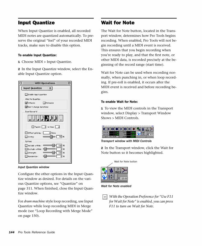
144
Input QuantizeWhen Input Quantize is enabled, all recorded MIDI notes are quantized automatically. To pre-serve the original “feel” of your recorded MIDI tracks, make sure to disable this option.
To enable Input Quantize:
1 Choose MIDI > Input Quantize.
2 In the Input Quantize window, select the En-able Input Quantize option.
Configure the other options in the Input Quan-tize window as desired. For details on the vari-ous Quantize options, see “Quantize” on page 311. When finished, close the Input Quan-tize window.
For drum machine style loop recording, use Input Quantize while loop recording MIDI in Merge mode (see “Loop Recording with Merge Mode” on page 150).
Input Quantize window
Pro Tools Reference Guide
Wait for NoteThe Wait for Note button, located in the Trans-port window, determines how Pro Tools begins recording. When enabled, Pro Tools will not be-gin recording until a MIDI event is received. This ensures that you begin recording when you’re ready to play, and that the first note, or other MIDI data, is recorded precisely at the be-ginning of the record range (start time).
Wait for Note can be used when recording nor-mally, when punching in, or when loop record-ing. If pre-roll is enabled, it occurs after the MIDI event is received and before recording be-gins.
To enable Wait for Note:
1 To view the MIDI controls in the Transport window, select Display > Transport Window Shows > MIDI Controls.
2 In the Transport window, click the Wait for Note button so it becomes highlighted.
Transport window with MIDI Controls
Wait for Note enabled
With the Operation Preference for “Use F11 for Wait for Note” is enabled, you can press F11 to turn on Wait for Note.
Wait for Note button
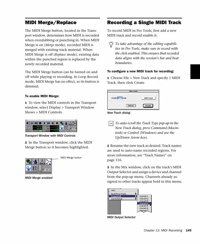
MIDI Merge/ReplaceThe MIDI Merge button, located in the Trans-port window, determines how MIDI is recorded when overdubbing or punching in. When MIDI Merge is on (Merge mode), recorded MIDI is merged with existing track material. When MIDI Merge is off (Replace mode), existing data within the punched region is replaced by the newly recorded material.
The MIDI Merge button can be turned on and off while playing or recording. In Loop Record mode, MIDI Merge has no effect, so its button is dimmed.
To enable MIDI Merge:
1 To view the MIDI controls in the Transport window, select Display > Transport Window Shows > MIDI Controls.
2 In the Transport window, click the MIDI Merge button so it becomes highlighted.
Transport Window with MIDI Controls
MIDI Merge enabled
MIDI Merge button
Recording a Single MIDI TrackTo record MIDI in Pro Tools, first add a new MIDI track and record enable it.
To configure a new MIDI track for recording:
1 Choose File > New Track and specify 1 MIDI Track, then click Create.
2 Rename the new track as desired. Track names are used to auto-name recorded regions. For more information, see “Track Names” on page 116.
3 In the Mix window, click on the track’s MIDI Output Selector and assign a device and channel from the pop-up menu. Channels already as-signed to other tracks appear bold in this menu.
To take advantage of the editing capabili-ties in Pro Tools, make sure to record with the click enabled. This ensures that recorded data aligns with the session’s bar and beat boundaries.
New Track dialog
To auto-scroll the Track Type pop-up in the New Track dialog, press Command (Macin-tosh) or Control (Windows) and use the Up/Down Arrow keys.
MIDI Output Selector
Chapter 13: MIDI Recording 145
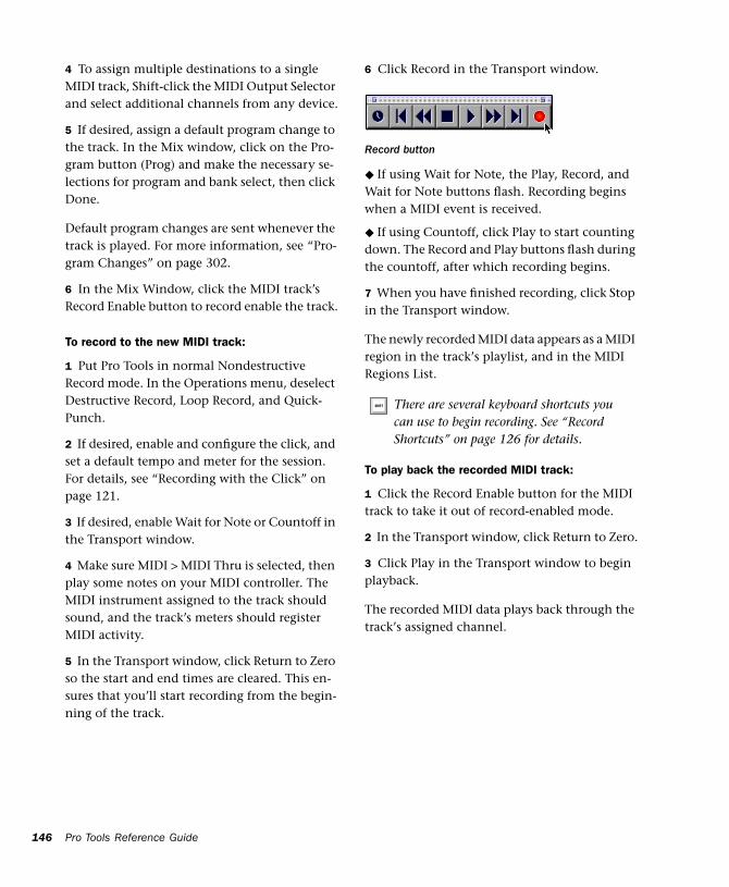
146
4 To assign multiple destinations to a single MIDI track, Shift-click the MIDI Output Selector and select additional channels from any device.
5 If desired, assign a default program change to the track. In the Mix window, click on the Pro-gram button (Prog) and make the necessary se-lections for program and bank select, then click Done.
Default program changes are sent whenever the track is played. For more information, see “Pro-gram Changes” on page 302.
6 In the Mix Window, click the MIDI track’s Record Enable button to record enable the track.
To record to the new MIDI track:
1 Put Pro Tools in normal Nondestructive Record mode. In the Operations menu, deselect Destructive Record, Loop Record, and Quick-Punch.
2 If desired, enable and configure the click, and set a default tempo and meter for the session. For details, see “Recording with the Click” on page 121.
3 If desired, enable Wait for Note or Countoff in the Transport window.
4 Make sure MIDI > MIDI Thru is selected, then play some notes on your MIDI controller. The MIDI instrument assigned to the track should sound, and the track’s meters should register MIDI activity.
5 In the Transport window, click Return to Zero so the start and end times are cleared. This en-sures that you’ll start recording from the begin-ning of the track.
Pro Tools Reference Guide
6 Click Record in the Transport window.
◆ If using Wait for Note, the Play, Record, and Wait for Note buttons flash. Recording begins when a MIDI event is received.
◆ If using Countoff, click Play to start counting down. The Record and Play buttons flash during the countoff, after which recording begins.
7 When you have finished recording, click Stop in the Transport window.
The newly recorded MIDI data appears as a MIDI region in the track’s playlist, and in the MIDI Regions List.
To play back the recorded MIDI track:
1 Click the Record Enable button for the MIDI track to take it out of record-enabled mode.
2 In the Transport window, click Return to Zero.
3 Click Play in the Transport window to begin playback.
The recorded MIDI data plays back through the track’s assigned channel.
Record button
There are several keyboard shortcuts you can use to begin recording. See “Record Shortcuts” on page 126 for details.
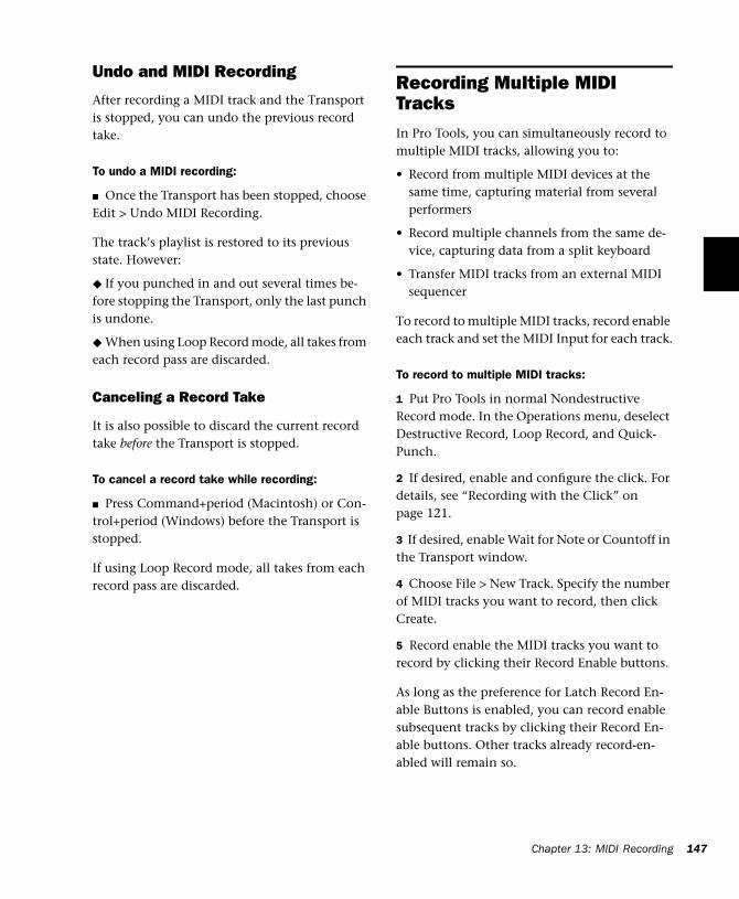
Undo and MIDI Recording
After recording a MIDI track and the Transport is stopped, you can undo the previous record take.
To undo a MIDI recording:
■ Once the Transport has been stopped, choose Edit > Undo MIDI Recording.
The track’s playlist is restored to its previous state. However:
◆ If you punched in and out several times be-fore stopping the Transport, only the last punch is undone.
◆ When using Loop Record mode, all takes from each record pass are discarded.
Canceling a Record Take
It is also possible to discard the current record take before the Transport is stopped.
To cancel a record take while recording:
■ Press Command+period (Macintosh) or Con-trol+period (Windows) before the Transport is stopped.
If using Loop Record mode, all takes from each record pass are discarded.
Recording Multiple MIDI TracksIn Pro Tools, you can simultaneously record to multiple MIDI tracks, allowing you to:
• Record from multiple MIDI devices at the same time, capturing material from several performers
• Record multiple channels from the same de-vice, capturing data from a split keyboard
• Transfer MIDI tracks from an external MIDI sequencer
To record to multiple MIDI tracks, record enable each track and set the MIDI Input for each track.
To record to multiple MIDI tracks:
1 Put Pro Tools in normal Nondestructive Record mode. In the Operations menu, deselect Destructive Record, Loop Record, and Quick-Punch.
2 If desired, enable and configure the click. For details, see “Recording with the Click” on page 121.
3 If desired, enable Wait for Note or Countoff in the Transport window.
4 Choose File > New Track. Specify the number of MIDI tracks you want to record, then click Create.
5 Record enable the MIDI tracks you want to record by clicking their Record Enable buttons.
As long as the preference for Latch Record En-able Buttons is enabled, you can record enable subsequent tracks by clicking their Record En-able buttons. Other tracks already record-en-abled will remain so.
Chapter 13: MIDI Recording 147
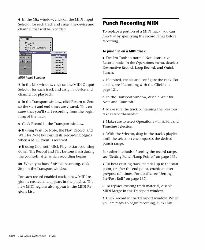
148
6 In the Mix window, click on the MIDI Input Selector for each track and assign the device and channel that will be recorded.
7 In the Mix window, click on the MIDI Output Selector for each track and assign a device and channel for playback.
8 In the Transport window, click Return to Zero so the start and end times are cleared. This en-sures that you’ll start recording from the begin-ning of the track.
9 Click Record in the Transport window.
◆ If using Wait for Note, the Play, Record, and Wait for Note buttons flash. Recording begins when a MIDI event is received.
◆ If using Countoff, click Play to start counting down. The Record and Play buttons flash during the countoff, after which recording begins.
10 When you have finished recording, click Stop in the Transport window.
For each record-enabled track, a new MIDI re-gion is created and appears in the playlist. The new MIDI regions also appear in the MIDI Re-gions List.
MIDI Input Selector
Pro Tools Reference Guide
Punch Recording MIDITo replace a portion of a MIDI track, you can punch in by specifying the record range before recording.
To punch in on a MIDI track:
1 Put Pro Tools in normal Nondestructive Record mode. In the Operations menu, deselect Destructive Record, Loop Record, and Quick-Punch.
2 If desired, enable and configure the click. For details, see “Recording with the Click” on page 121.
3 In the Transport window, disable Wait for Note and Countoff.
4 Make sure the track containing the previous take is record-enabled.
5 Make sure to select Operations > Link Edit and Timeline Selection.
6 With the Selector, drag in the track’s playlist until the selection encompasses the desired punch range.
For other methods of setting the record range, see “Setting Punch/Loop Points” on page 135.
7 To hear existing track material up to the start point, or after the end point, enable and set pre/post-roll times. For details, see “Setting Pre/Post-Roll” on page 137.
8 To replace existing track material, disable MIDI Merge in the Transport window.
9 Click Record in the Transport window. When you are ready to begin recording, click Play.
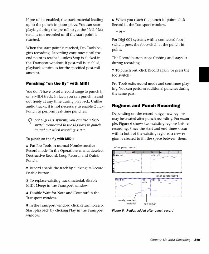
If pre-roll is enabled, the track material leading up to the punch-in point plays. You can start playing during the pre-roll to get the “feel.” Ma-terial is not recorded until the start point is reached.
When the start point is reached, Pro Tools be-gins recording. Recording continues until the end point is reached, unless Stop is clicked in the Transport window. If post-roll is enabled, playback continues for the specified post-roll amount.
Punching “on the fly” with MIDI
You don’t have to set a record range to punch in on a MIDI track. In fact, you can punch in and out freely at any time during playback. Unlike audio tracks, it is not necessary to enable Quick-Punch to perform real-time punches.
To punch on the fly with MIDI:
1 Put Pro Tools in normal Nondestructive Record mode. In the Operations menu, deselect Destructive Record, Loop Record, and Quick-Punch.
2 Record enable the track by clicking its Record Enable button.
3 To replace existing track material, disable MIDI Merge in the Transport window.
4 Disable Wait for Note and Countoff in the Transport window.
5 In the Transport window, click Return to Zero. Start playback by clicking Play in the Transport window.
For Digi 001 systems, you can use a foot-switch (connected to the I/O Box) to punch in and out when recording MIDI.
6 When you reach the punch-in point, click Record in the Transport window.
– or –
For Digi 001 systems with a connected foot-switch, press the footswitch at the punch-in point.
The Record button stops flashing and stays lit during recording.
7 To punch out, click Record again (or press the footswitch).
Pro Tools exits record mode and continues play-ing. You can perform additional punches during the same pass.
Regions and Punch Recording
Depending on the record range, new regions may be created after punch recording. For exam-ple, Figure 6 shows two existing regions before recording. Since the start and end times occur within both of the existing regions, a new re-gion is created to fill the space between them.
Figure 6. Region added after punch record
before punch record
after punch record
new regionnewly recorded
material
Ch
apter 13: MIDI Recording 149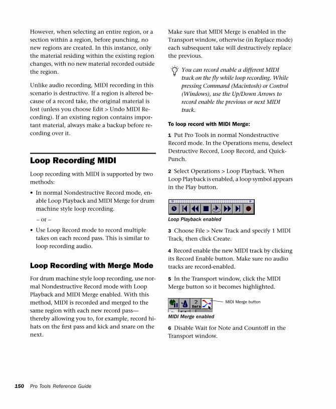
150
However, when selecting an entire region, or a section within a region, before punching, no new regions are created. In this instance, only the material residing within the existing region changes, with no new material recorded outside the region.
Unlike audio recording, MIDI recording in this scenario is destructive. If a region is altered be-cause of a record take, the original material is lost (unless you choose Edit > Undo MIDI Re-cording). If an existing region contains impor-tant material, always make a backup before re-cording over it.
Loop Recording MIDILoop recording with MIDI is supported by two methods:
• In normal Nondestructive Record mode, en-able Loop Playback and MIDI Merge for drum machine style loop recording.
– or –
• Use Loop Record mode to record multiple takes on each record pass. This is similar to loop recording audio.
Loop Recording with Merge Mode
For drum machine style loop recording, use nor-mal Nondestructive Record mode with Loop Playback and MIDI Merge enabled. With this method, MIDI is recorded and merged to the same region with each new record pass—thereby allowing you to, for example, record hi-hats on the first pass and kick and snare on the next.
Pro Tools Reference Guide
Make sure that MIDI Merge is enabled in the Transport window, otherwise (in Replace mode) each subsequent take will destructively replace the previous.
To loop record with MIDI Merge:
1 Put Pro Tools in normal Nondestructive Record mode. In the Operations menu, deselect Destructive Record, Loop Record, and Quick-Punch.
2 Select Operations > Loop Playback. When Loop Playback is enabled, a loop symbol appears in the Play button.
3 Choose File > New Track and specify 1 MIDI Track, then click Create.
4 Record enable the new MIDI track by clicking its Record Enable button. Make sure no audio tracks are record-enabled.
5 In the Transport window, click the MIDI Merge button so it becomes highlighted.
6 Disable Wait for Note and Countoff in the Transport window.
You can record enable a different MIDI track on the fly while loop recording. While pressing Command (Macintosh) or Control (Windows), use the Up/Down Arrows to record enable the previous or next MIDI track.
Loop Playback enabled
MIDI Merge enabled
MIDI Merge button
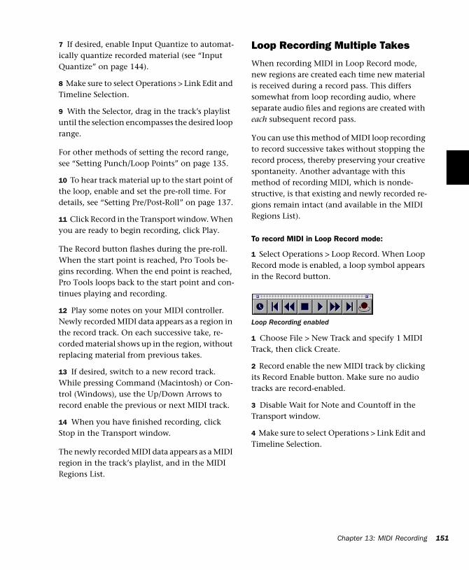
7 If desired, enable Input Quantize to automat-ically quantize recorded material (see “Input Quantize” on page 144).
8 Make sure to select Operations > Link Edit and Timeline Selection.
9 With the Selector, drag in the track’s playlist until the selection encompasses the desired loop range.
For other methods of setting the record range, see “Setting Punch/Loop Points” on page 135.
10 To hear track material up to the start point of the loop, enable and set the pre-roll time. For details, see “Setting Pre/Post-Roll” on page 137.
11 Click Record in the Transport window. When you are ready to begin recording, click Play.
The Record button flashes during the pre-roll. When the start point is reached, Pro Tools be-gins recording. When the end point is reached, Pro Tools loops back to the start point and con-tinues playing and recording.
12 Play some notes on your MIDI controller. Newly recorded MIDI data appears as a region in the record track. On each successive take, re-corded material shows up in the region, without replacing material from previous takes.
13 If desired, switch to a new record track. While pressing Command (Macintosh) or Con-trol (Windows), use the Up/Down Arrows to record enable the previous or next MIDI track.
14 When you have finished recording, click Stop in the Transport window.
The newly recorded MIDI data appears as a MIDI region in the track’s playlist, and in the MIDI Regions List.
Loop Recording Multiple Takes
When recording MIDI in Loop Record mode, new regions are created each time new material is received during a record pass. This differs somewhat from loop recording audio, where separate audio files and regions are created with each subsequent record pass.
You can use this method of MIDI loop recording to record successive takes without stopping the record process, thereby preserving your creative spontaneity. Another advantage with this method of recording MIDI, which is nonde-structive, is that existing and newly recorded re-gions remain intact (and available in the MIDI Regions List).
To record MIDI in Loop Record mode:
1 Select Operations > Loop Record. When Loop Record mode is enabled, a loop symbol appears in the Record button.
1 Choose File > New Track and specify 1 MIDI Track, then click Create.
2 Record enable the new MIDI track by clicking its Record Enable button. Make sure no audio tracks are record-enabled.
3 Disable Wait for Note and Countoff in the Transport window.
4 Make sure to select Operations > Link Edit and Timeline Selection.
Loop Recording enabled
Chapter 13: MIDI Recording 151
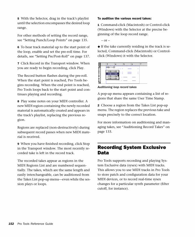
152
5 With the Selector, drag in the track’s playlist until the selection encompasses the desired loop range.
For other methods of setting the record range, see “Setting Punch/Loop Points” on page 135.
6 To hear track material up to the start point of the loop, enable and set the pre-roll time. For details, see “Setting Pre/Post-Roll” on page 137.
7 Click Record in the Transport window. When you are ready to begin recording, click Play.
The Record button flashes during the pre-roll. When the start point is reached, Pro Tools be-gins recording. When the end point is reached, Pro Tools loops back to the start point and con-tinues playing and recording.
8 Play some notes on your MIDI controller. A new MIDI region containing the newly recorded material is automatically created and appears in the track’s playlist, replacing the previous re-gion.
Regions are replaced (non-destructively) during subsequent record passes when new MIDI mate-rial is received.
9 When you have finished recording, click Stop in the Transport window. The most recently re-corded take is left in the record track.
The recorded takes appear as regions in the MIDI Regions List and are numbered sequen-tially. The takes, which are the same length and easily interchangeable, can be auditioned from the Takes List pop-up menu—even while the ses-sion plays or loops.
Pro Tools Reference Guide
To audition the various record takes:
1 Command-click (Macintosh) or Control-click (Windows) with the Selector at the precise be-ginning of the loop record range.
– or –
◆ If the take currently residing in the track is se-lected, Command-click (Macintosh) or Control-click (Windows) it with the Selector.
A pop-up menu appears containing a list of re-gions that share the same User Time Stamp.
2 Choose a region from the Takes List pop-up menu. The region replaces the previous take and snaps precisely to the correct location.
For more information on auditioning and man-aging takes, see “Auditioning Record Takes” on page 133.
Recording System Exclusive DataPro Tools supports recording and playing Sys-tem Exclusive data (sysex) with MIDI tracks. This allows you to use MIDI tracks in Pro Tools to store patch and configuration data for your MIDI devices, or to record real-time sysex changes for a particular synth parameter (filter cutoff, for instance).
Auditioning loop record takes
To record a sysex dump at the beginning of a MIDI track:
1 Make sure that the MIDI OUT for the device sending the sysex is connected to your MIDI in-terface’s MIDI IN.
2 Put Pro Tools in normal Nondestructive Record mode. In the Operations menu, deselect Destructive Record, Loop Record, and Quick-Punch.
3 In the MIDI Input Filter, enable recording of System Exclusive data.
4 Choose File > New Track and specify 1 MIDI Track, then click Create.
5 Record enable the new MIDI track by clicking its Record Enable button.
6 Enable Wait for Note in the Transport win-dow.
7 In the Transport window, click Return to Zero so the start and end times are cleared. This en-sures that you’ll start recording from the begin-ning of the track.
8 When you are ready to begin recording, click Record in the Transport window.
The Record, Play, and Wait for Note buttons flash, indicating that Pro Tools is waiting for MIDI data.
9 Initiate the sysex transfer from the MIDI de-vice. When receiving the MIDI data, Pro Tools automatically begins recording.
10 When the transfer is complete, click Stop in the Transport window.
The newly recorded MIDI data appears as a MIDI region in the track’s playlist, and in the MIDI Regions List. MIDI regions that contain System Exclusive data appear blank when the track’s Display Format is set to Regions.
To see the sysex event blocks, which indicate the location of the data, set the track to display Sysex. For details on moving and copying of sysex data, see “System Exclusive Events” on page 305.
To resend the sysex from Pro Tools:
1 For the device receiving the System Exclusive data, make sure its MIDI IN is connected to your MIDI interface’s MIDI OUT.
Also, make sure the device is set to receive sysex. Some devices require that memory protect be off.
2 For the previously recorded track, click its Record button to take it out of record-enabled mode.
3 In the Mix window, click on the track’s MIDI Device/Channel Selector and assign the device from the pop-up menu.
4 In the Transport window, click Return to Zero.
5 Click Play in the Transport window to begin playback. Pro Tools begins playing and trans-mits the previously recorded sysex to the as-signed MIDI device.
Chapter 13: MIDI Recording 153

154
Pro Tools Reference Guide
Chapter 14: Advanced Recording
Using QuickPunchPro Tools features an intelligent on-the-fly punch capability called QuickPunch. Quick-Punch lets you instantaneously punch in and out on record-enabled audio tracks during play-back by merely clicking the Record button in the Transport window.
When using QuickPunch, Pro Tools starts re-cording a new audio file when you begin play-back, automatically defining and naming re-gions in that file at each punch-in/out point. Up to 100 of these “running punches” can be per-formed during a single pass. Unlike normal punch recording (see “Punch Recording Audio” on page 131), QuickPunch provides instanta-neous monitor switching on punch-out. All QuickPunch recording is nondestructive.
NOTE: You don’t need to use QuickPunch to punch on the fly with MIDI tracks. This capability is available in normal Nondestructive Record mode, and in Destructive Record mode.
For Digi 001 systems, you can use a foot-switch (connected to the I/O box) to punch in and out when recording with Quick-Punch.
QuickPunch Crossfade Length
Pro Tools can automatically write a crossfade for each punch point when using QuickPunch. The length for these crossfades is set with the Quick-Punch Crossfade Length option in the Editing Preferences.
To set the QuickPunch Crossfade Length:
1 Choose Setups > Preferences and click Editing.
2 Enter a value (in msec) for the QuickPunch CrossFade Length.
A good general-purpose crossfade length for punches is 4 milliseconds. If you set the prefer-ence to zero, Pro Tools will not create any cross-fades at the punch-in/out points.
3 Click Done.
If a value other than zero is specified for the QuickPunch Crossfade Length, QuickPunch writes a pre-crossfade at the punch-in point (which occurs up to but not into the punched region boundary), and a post-crossfade at the punch-out point (which occurs after the punched region).
Even if the QuickPunch Crossfade Length is set to zero, Pro Tools always executes a 4 millisecond “monitor only” crossfade (which is not written to disk) to avoid distracting pops or clicks that might occur as you enter and exit record mode.
Chapter 14: Advanced Recording 155
156
QuickPunch crossfades can later be edited in the same manner as standard crossfades. For details, see “Using Crossfades” on page 241.
QuickPunch Guidelines for TDM Systems
When using QuickPunch on TDM systems, two voices are required for each record-enabled, mono track. For example, a Pro Tools 24 system with 32 voices can simultaneously record on up to 16 mono tracks with QuickPunch. Quick-Punch with stereo tracks requires twice the number of voices.
If the required number of voices for the record-enabled tracks is not available when switching to QuickPunch mode, you’ll be prompted to free up the necessary voices.
To free up voices on tracks that are not record-enabled, and do not need to be heard while recording:
■ Set voice assignments for tracks to Off.
– or –
■ Make tracks inactive.
As necessary, voices in use by other tracks, which are not record-enabled, may be stolen while recording with QuickPunch. Priority for tracks while recording with QuickPunch are as follows:
• Tracks with assigned voices that are not record-enabled
• Tracks with assigned voices that are record-en-abled
• Auto-voiced tracks that are not record-en-abled
• Auto-voiced tracks that are record-enabled
Pro Tools Reference Guide
If the session has plenty of available voices, you may have no trouble using QuickPunch with auto-voiced tracks. However, if you are running out of voices, and want to ensure that a track will heard when recording with QuickPunch, as-sign it a voice.
QuickPunch and Auto Voice (TDM Systems Only)
When using QuickPunch with a 64-voice system with, make sure to set the voice assignment for each audio track to Auto. This ensures that Pro Tools will automatically handle the distri-bution of voices between the two sets of voices (1–32 and 33–64).
If you do not use auto-voicing, the voices must be evenly distributed between the two DSP en-gines. For example, to use QuickPunch on 32 tracks without auto-voicing, tracks 1–16 must be assigned to voices 1–16 and tracks 17–32 must be assigned to voices 33–48.
QuickPunch Guidelines for Pro Tools LEDigi 001 and Audiomedia III
For non-TDM systems, the maximum number of mono tracks that can be simultaneously re-corded with QuickPunch in a session with 24 audio tracks is 8.
To simultaneously record more tracks than this with QuickPunch, you’ll need to reduce the number of tracks in the session. For example, a session with 20 audio tracks can record 10 mono tracks with QuickPunch, and a session with 16 audio tracks can record 12.
With Pro Tools LE, QuickPunch uses CPU processing power, and may reduce the num-ber of tracks and plug-ins you can use.
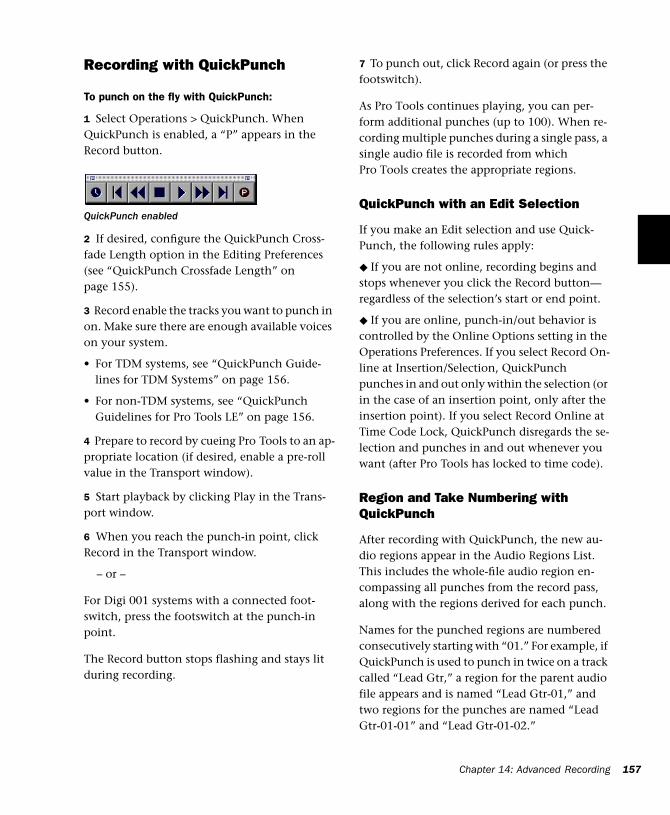
Recording with QuickPunch
To punch on the fly with QuickPunch:
1 Select Operations > QuickPunch. When QuickPunch is enabled, a “P” appears in the Record button.
2 If desired, configure the QuickPunch Cross-fade Length option in the Editing Preferences (see “QuickPunch Crossfade Length” on page 155).
3 Record enable the tracks you want to punch in on. Make sure there are enough available voices on your system.
• For TDM systems, see “QuickPunch Guide-lines for TDM Systems” on page 156.
• For non-TDM systems, see “QuickPunch Guidelines for Pro Tools LE” on page 156.
4 Prepare to record by cueing Pro Tools to an ap-propriate location (if desired, enable a pre-roll value in the Transport window).
5 Start playback by clicking Play in the Trans-port window.
6 When you reach the punch-in point, click Record in the Transport window.
– or –
For Digi 001 systems with a connected foot-switch, press the footswitch at the punch-in point.
The Record button stops flashing and stays lit during recording.
QuickPunch enabled
7 To punch out, click Record again (or press the footswitch).
As Pro Tools continues playing, you can per-form additional punches (up to 100). When re-cording multiple punches during a single pass, a single audio file is recorded from which Pro Tools creates the appropriate regions.
QuickPunch with an Edit Selection
If you make an Edit selection and use Quick-Punch, the following rules apply:
◆ If you are not online, recording begins and stops whenever you click the Record button—regardless of the selection’s start or end point.
◆ If you are online, punch-in/out behavior is controlled by the Online Options setting in the Operations Preferences. If you select Record On-line at Insertion/Selection, QuickPunch punches in and out only within the selection (or in the case of an insertion point, only after the insertion point). If you select Record Online at Time Code Lock, QuickPunch disregards the se-lection and punches in and out whenever you want (after Pro Tools has locked to time code).
Region and Take Numbering with QuickPunch
After recording with QuickPunch, the new au-dio regions appear in the Audio Regions List. This includes the whole-file audio region en-compassing all punches from the record pass, along with the regions derived for each punch.
Names for the punched regions are numbered consecutively starting with “01.” For example, if QuickPunch is used to punch in twice on a track called “Lead Gtr,” a region for the parent audio file appears and is named “Lead Gtr-01,” and two regions for the punches are named “Lead Gtr-01-01” and “Lead Gtr-01-02.”
Chapter 14: Advanced Recording 157
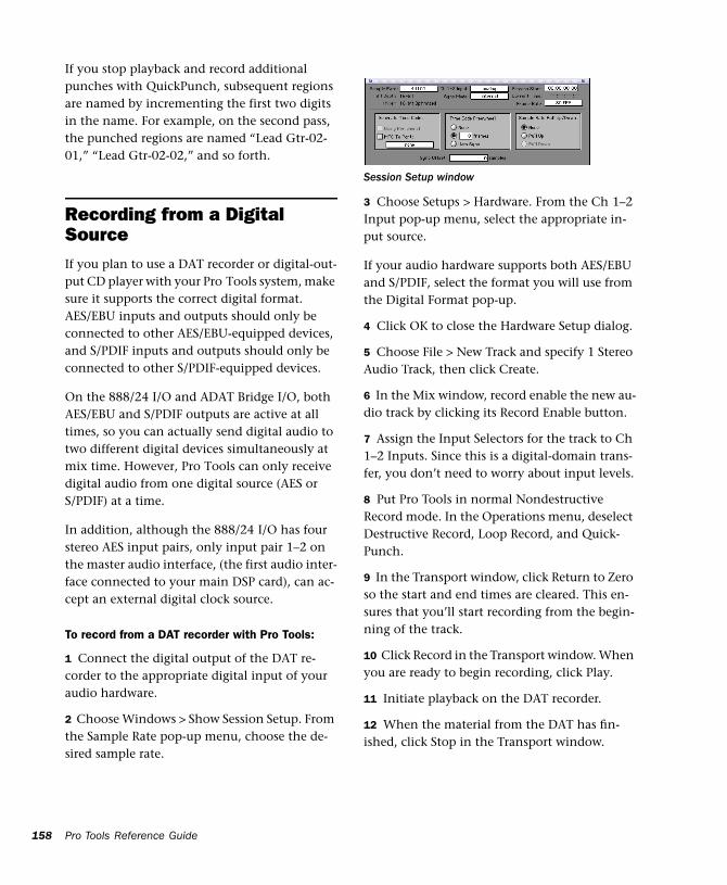
158
If you stop playback and record additional punches with QuickPunch, subsequent regions are named by incrementing the first two digits in the name. For example, on the second pass, the punched regions are named “Lead Gtr-02-01,” “Lead Gtr-02-02,” and so forth.
Recording from a Digital SourceIf you plan to use a DAT recorder or digital-out-put CD player with your Pro Tools system, make sure it supports the correct digital format. AES/EBU inputs and outputs should only be connected to other AES/EBU-equipped devices, and S/PDIF inputs and outputs should only be connected to other S/PDIF-equipped devices.
On the 888/24 I/O and ADAT Bridge I/O, both AES/EBU and S/PDIF outputs are active at all times, so you can actually send digital audio to two different digital devices simultaneously at mix time. However, Pro Tools can only receive digital audio from one digital source (AES or S/PDIF) at a time.
In addition, although the 888/24 I/O has four stereo AES input pairs, only input pair 1–2 on the master audio interface, (the first audio inter-face connected to your main DSP card), can ac-cept an external digital clock source.
To record from a DAT recorder with Pro Tools:
1 Connect the digital output of the DAT re-corder to the appropriate digital input of your audio hardware.
2 Choose Windows > Show Session Setup. From the Sample Rate pop-up menu, choose the de-sired sample rate.
Pro Tools Reference Guide
3 Choose Setups > Hardware. From the Ch 1–2 Input pop-up menu, select the appropriate in-put source.
If your audio hardware supports both AES/EBU and S/PDIF, select the format you will use from the Digital Format pop-up.
4 Click OK to close the Hardware Setup dialog.
5 Choose File > New Track and specify 1 Stereo Audio Track, then click Create.
6 In the Mix window, record enable the new au-dio track by clicking its Record Enable button.
7 Assign the Input Selectors for the track to Ch 1–2 Inputs. Since this is a digital-domain trans-fer, you don’t need to worry about input levels.
8 Put Pro Tools in normal Nondestructive Record mode. In the Operations menu, deselect Destructive Record, Loop Record, and Quick-Punch.
9 In the Transport window, click Return to Zero so the start and end times are cleared. This en-sures that you’ll start recording from the begin-ning of the track.
10 Click Record in the Transport window. When you are ready to begin recording, click Play.
11 Initiate playback on the DAT recorder.
12 When the material from the DAT has fin-ished, click Stop in the Transport window.
Session Setup window
After a Digital Transfer
After you have finished recording digitally, set the Sync Mode pop-up menu in the Session Setup window back to Internal. Otherwise, Pro Tools will not switch back to its own inter-nal clock and will not record or play audio prop-erly. Failure to switch back to Internal sync typ-ically results in pitch problems (fast or slow playback) or DAE errors, since a DAT recorder or CD Recorder that is idle can default to a differ-ent sample rate or stop outputting a sample rate clock altogether.
Half-Speed Recording and PlaybackPro Tools lets you play and record at half-speed. This capability is similar to that of a tape deck where you can record material at half-speed and then play it back at normal speed (up an octave) for special effects.
To record at half-speed:
1 Press Command+Shift+Spacebar (Macintosh) or Control+Shift+Spacebar (Windows). Record-ing begins and all existing track material plays at half-speed.
2 When you have finished recording, click Stop.
When played at normal speed, the material re-corded at half-speed plays twice as fast (up an octave).
Use half-speed recording to record difficult to play MIDI tracks. This allows you to hear audio tracks while recording. Half-speed re-cording and playback do not affect how MIDI tracks sound when played.
To play at half-speed
1 Press Shift+Spacebar. Playback begins and track material plays at half-speed. If any tracks were recorded at half-speed, they play at normal speed.
2 Click Stop in the Transport window to stop playback.
Use half-speed playback to learn or tran-scribe difficult passages in recorded tracks.
Chapter 14: Advanced Recording 159

160
Pro Tools Reference Guide
Part IV: Editing
161

162
Chapter 15: Editing Basics
Pro Tools EditingThe Edit window in Pro Tools provides a power-ful collection of tools for editing and assembling audio and MIDI tracks. Track material can be ed-ited non-destructively and in real time during playback.
Nondestructive Editing
The vast majority of audio editing in Pro Tools is nondestructive. Whether cutting, pasting, trim-ming, separating, or clearing regions, you are only performing these functions on a map of the actual audio data. The source audio files re-main untouched. If a particular process or tool works destructively (that is, if it can perma-nently change audio files on your hard disk), this guide alerts you.
While editing for MIDI tracks is in some in-stances destructive, with a few precautions you can keep important MIDI tracks and regions safe when performing edits (see “Nondestructive MIDI Editing” on page 172).
Editing During Playback
Pro Tools lets you perform many editing tasks while the session plays. This powerful capability allows you to interactively modify and edit a session, hearing the changes as you make them. You’ll find many instances where you can use this capability to increase your productivity when working with a session.
Following are just a few examples of editing that can be performed while your tracks loop or play:
• Capture, separate, and trim regions
• Place, spot, or rearrange regions
• Add fades or crossfades to audio regions
• Transpose, quantize, and otherwise modify MIDI tracks
• Nudge audio or MIDI regions
• Audition different playlists
• Adjust or scale automation data
• Process audio with an AudioSuite plug-in
There are a few things that cannot be changed while Pro Tools plays. These include assigning TDM plug-ins to audio tracks, routing to sends, and assigning outputs.
Chapter 15: Editing Basics 163
164
Track MaterialEach time you record or import audio and MIDI, Pro Tools creates regions for the new track data, which not only indicate where the material be-gins and ends, but also provides good feedback on its general shape and content. When you record additional takes, or “punch in” on a spe-cific location within a track, Pro Tools creates additional regions.
Regions are also created by cutting and pasting, resizing, separating, and re-capturing existing regions. Regions in a session are listed in the Au-dio Regions List and MIDI Regions List, where they can be dragged to existing tracks. A track can contain any number of regions, in any ar-rangement. The order and location of regions in a track define its playlist.
Region Types
Following is a description of the different region types and how they are created:
Whole-File Audio Regions These audio regions are created when recording or importing audio, consolidating existing regions, and when non-destructively processing with an AudioSuite plug-in. Whole-file audio regions reference an entire audio file that resides on your hard drive. Whole-file audio regions are displayed in bold in the Audio Regions List (see “The Audio and MIDI Regions Lists” on page 175). Normal re-gions reference only a portion of the parent au-dio file and are created in the course of editing and, in some instances, when punch recording.
Pro Tools Reference Guide
User-Defined Regions These are regions that are explicitly defined, such as when you record or import audio or MIDI; capture, separate, or con-solidate a selection; trim a whole-file audio re-gion; and rename an existing region.
Auto-Created Regions These regions are auto-matically created in the course of editing, and, in some instances, when punch recording over existing regions. Since these regions can accu-mulate rapidly in a session, you can hide them so they don’t appear in the Audio and MIDI Re-gions List (see “Managing Regions” on page 256). Auto-created regions can be turned into user-defined regions by renaming them.
Offline Regions Regions are offline when their as-sociated audio files cannot be located, or are not available, when opening a session or importing a track. Offline regions appear in the Audio Re-gions List as italicized and dimmed. Offline re-gions appear in playlists as light blue regions with italicized names. Offline regions can be ed-ited like other regions, but they cannot be pro-cessed with AudioSuite plug-ins.
Multi-Channel Regions These regions, which are displayed as a single region in the Audio Regions List, reference multiple regions and audio files for stereo and surround tracks. Multi-channel regions can be expanded (by clicking the trian-gle next to their name) to see the individual channels, which can be dragged independently to tracks.
Track View
The track View determines which data is dis-played and edited in the track’s playlist area.
Audio tracks can be set to Blocks, Waveform, Vol-ume, Pan, Mute, or any plug-in parameters that have been automated. Except when editing au-tomation data, audio tracks are usually set to
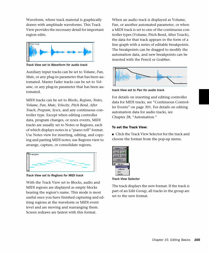
Waveform, where track material is graphically drawn with amplitude waveforms. This Track View provides the necessary detail for important region edits.
Auxiliary input tracks can be set to Volume, Pan, Mute, or any plug-in parameter that has been au-tomated. Master Fader tracks can be set to Vol-ume, or any plug-in parameter that has been au-tomated.
MIDI tracks can be set to Blocks, Regions, Notes, Volume, Pan, Mute, Velocity, Pitch Bend, After Touch, Program, Sysex, and any continuous con-troller type. Except when editing controller data, program changes, or sysex events, MIDI tracks are usually set to Notes or Regions, each of which displays notes in a “piano roll” format. Use Notes view for inserting, editing, and copy-ing and pasting MIDI notes; use Regions view to arrange, capture, or consolidate regions.
With the Track View set to Blocks, audio and MIDI regions are displayed as empty blocks bearing the region’s name. This mode is most useful once you have finished capturing and ed-iting regions at the waveform or MIDI event level and are moving and rearranging them. Screen redraws are fastest with this format.
Track View set to Waveform for audio track
Track View set to Regions for MIDI track
When an audio track is displayed as Volume, Pan, or another automated parameter, or when a MIDI track is set to one of the continuous con-troller types (Volume, Pitch Bend, After Touch), the data for that track appears in the form of a line graph with a series of editable breakpoints. The breakpoints can be dragged to modify the automation data, and new breakpoints can be inserted with the Pencil or Grabber.
For details on inserting and editing controller data for MIDI tracks, see “Continuous Control-ler Events” on page 301. For details on editing automation data for audio tracks, see Chapter 28, “Automation.”
To set the Track View:
■ Click the Track View Selector for the track and choose the format from the pop-up menu.
The track displays the new format. If the track is part of an Edit Group, all tracks in the group are set to the new format.
track View set to Pan for audio track
Track View Selector
Chapter 15: Editing Basics 165
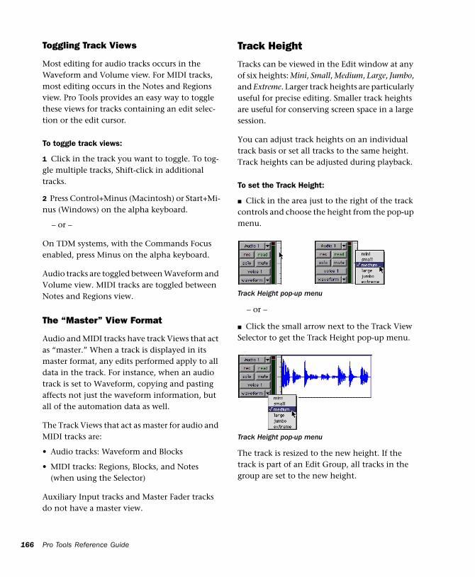
166
Toggling Track Views
Most editing for audio tracks occurs in the Waveform and Volume view. For MIDI tracks, most editing occurs in the Notes and Regions view. Pro Tools provides an easy way to toggle these views for tracks containing an edit selec-tion or the edit cursor.
To toggle track views:
1 Click in the track you want to toggle. To tog-gle multiple tracks, Shift-click in additional tracks.
2 Press Control+Minus (Macintosh) or Start+Mi-nus (Windows) on the alpha keyboard.
– or –
On TDM systems, with the Commands Focus enabled, press Minus on the alpha keyboard.
Audio tracks are toggled between Waveform and Volume view. MIDI tracks are toggled between Notes and Regions view.
The “Master” View Format
Audio and MIDI tracks have track Views that act as “master.” When a track is displayed in its master format, any edits performed apply to all data in the track. For instance, when an audio track is set to Waveform, copying and pasting affects not just the waveform information, but all of the automation data as well.
The Track Views that act as master for audio and MIDI tracks are:
• Audio tracks: Waveform and Blocks
• MIDI tracks: Regions, Blocks, and Notes (when using the Selector)
Auxiliary Input tracks and Master Fader tracks do not have a master view.
Pro Tools Reference Guide
Track Height
Tracks can be viewed in the Edit window at any of six heights: Mini, Small, Medium, Large, Jumbo, and Extreme. Larger track heights are particularly useful for precise editing. Smaller track heights are useful for conserving screen space in a large session.
You can adjust track heights on an individual track basis or set all tracks to the same height. Track heights can be adjusted during playback.
To set the Track Height:
■ Click in the area just to the right of the track controls and choose the height from the pop-up menu.
– or –
■ Click the small arrow next to the Track View Selector to get the Track Height pop-up menu.
The track is resized to the new height. If the track is part of an Edit Group, all tracks in the group are set to the new height.
Track Height pop-up menu
Track Height pop-up menu
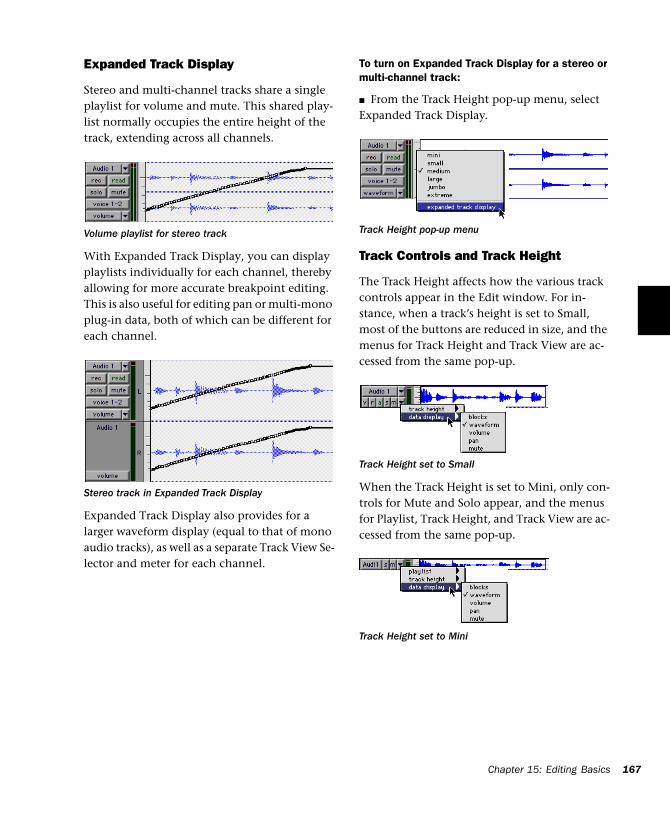
Expanded Track Display
Stereo and multi-channel tracks share a single playlist for volume and mute. This shared play-list normally occupies the entire height of the track, extending across all channels.
With Expanded Track Display, you can display playlists individually for each channel, thereby allowing for more accurate breakpoint editing. This is also useful for editing pan or multi-mono plug-in data, both of which can be different for each channel.
Expanded Track Display also provides for a larger waveform display (equal to that of mono audio tracks), as well as a separate Track View Se-lector and meter for each channel.
Volume playlist for stereo track
Stereo track in Expanded Track Display
To turn on Expanded Track Display for a stereo or multi-channel track:
■ From the Track Height pop-up menu, select Expanded Track Display.
Track Controls and Track Height
The Track Height affects how the various track controls appear in the Edit window. For in-stance, when a track’s height is set to Small, most of the buttons are reduced in size, and the menus for Track Height and Track View are ac-cessed from the same pop-up.
When the Track Height is set to Mini, only con-trols for Mute and Solo appear, and the menus for Playlist, Track Height, and Track View are ac-cessed from the same pop-up.
Track Height pop-up menu
Track Height set to Small
Track Height set to Mini
Chapter 15: Editing Basics 167
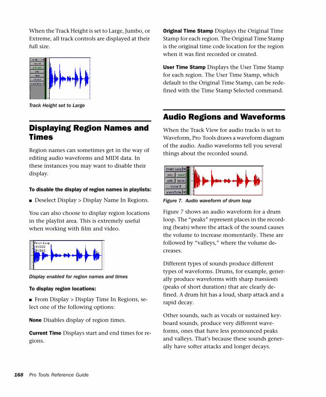
168
When the Track Height is set to Large, Jumbo, or Extreme, all track controls are displayed at their full size.
Displaying Region Names and TimesRegion names can sometimes get in the way of editing audio waveforms and MIDI data. In these instances you may want to disable their display.
To disable the display of region names in playlists:
■ Deselect Display > Display Name In Regions.
You can also choose to display region locations in the playlist area. This is extremely useful when working with film and video.
To display region locations:
■ From Display > Display Time In Regions, se-lect one of the following options:
None Disables display of region times.
Current Time Displays start and end times for re-gions.
Track Height set to Large
Display enabled for region names and times
Pro Tools Reference Guide
Original Time Stamp Displays the Original Time Stamp for each region. The Original Time Stamp is the original time code location for the region when it was first recorded or created.
User Time Stamp Displays the User Time Stamp for each region. The User Time Stamp, which default to the Original Time Stamp, can be rede-fined with the Time Stamp Selected command.
Audio Regions and WaveformsWhen the Track View for audio tracks is set to Waveform, Pro Tools draws a waveform diagram of the audio. Audio waveforms tell you several things about the recorded sound.
Figure 7 shows an audio waveform for a drum loop. The “peaks” represent places in the record-ing (beats) where the attack of the sound causes the volume to increase momentarily. These are followed by “valleys,” where the volume de-creases.
Different types of sounds produce different types of waveforms. Drums, for example, gener-ally produce waveforms with sharp transients (peaks of short duration) that are clearly de-fined. A drum hit has a loud, sharp attack and a rapid decay.
Other sounds, such as vocals or sustained key-board sounds, produce very different wave-forms, ones that have less pronounced peaks and valleys. That’s because these sounds gener-ally have softer attacks and longer decays.
Figure 7. Audio waveform of drum loop
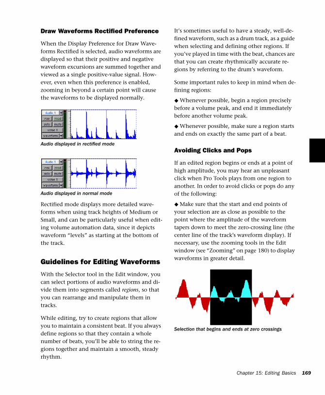
Draw Waveforms Rectified Preference
When the Display Preference for Draw Wave-forms Rectified is selected, audio waveforms are displayed so that their positive and negative waveform excursions are summed together and viewed as a single positive-value signal. How-ever, even when this preference is enabled, zooming in beyond a certain point will cause the waveforms to be displayed normally.
Rectified mode displays more detailed wave-forms when using track heights of Medium or Small, and can be particularly useful when edit-ing volume automation data, since it depicts waveform “levels” as starting at the bottom of the track.
Guidelines for Editing Waveforms
With the Selector tool in the Edit window, you can select portions of audio waveforms and di-vide them into segments called regions, so that you can rearrange and manipulate them in tracks.
While editing, try to create regions that allow you to maintain a consistent beat. If you always define regions so that they contain a whole number of beats, you’ll be able to string the re-gions together and maintain a smooth, steady rhythm.
Audio displayed in rectified mode
Audio displayed in normal mode
It’s sometimes useful to have a steady, well-de-fined waveform, such as a drum track, as a guide when selecting and defining other regions. If you’ve played in time with the beat, chances are that you can create rhythmically accurate re-gions by referring to the drum’s waveform.
Some important rules to keep in mind when de-fining regions:
◆ Whenever possible, begin a region precisely before a volume peak, and end it immediately before another volume peak.
◆ Whenever possible, make sure a region starts and ends on exactly the same part of a beat.
Avoiding Clicks and Pops
If an edited region begins or ends at a point of high amplitude, you may hear an unpleasant click when Pro Tools plays from one region to another. In order to avoid clicks or pops do any of the following:
◆ Make sure that the start and end points of your selection are as close as possible to the point where the amplitude of the waveform tapers down to meet the zero-crossing line (the center line of the track’s waveform display). If necessary, use the zooming tools in the Edit window (see “Zooming” on page 180) to display waveforms in greater detail.
Selection that begins and ends at zero crossings
Chapter 15: Editing Basics 169
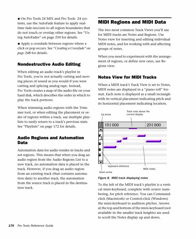
170
◆ On Pro Tools 24 MIX and Pro Tools 24 sys-tems, use the AutoFade feature to apply real-time fade-ins/outs to all region boundaries that do not touch or overlap other regions. See “Us-ing AutoFades” on page 250 for details.
◆ Apply a crossfade between regions where a click or pop occurs. See “Creating a Crossfade” on page 248 for details.
Nondestructive Audio Editing
When editing an audio track’s playlist in Pro Tools, you’re not actually cutting and mov-ing pieces of sound as you would if you were cutting and splicing analog tape. Instead, Pro Tools creates a map of the audio file on your hard disk, which describes the order in which to play the track portions.
When trimming audio regions with the Trim-mer tool, or when editing the placement or or-der of regions within a track, use multiple play-lists to easily return to a track’s previous state. See “Playlists” on page 172 for details.
Audio Regions and Automation Data
Automation data for audio resides in tracks and not regions. This means that when you drag an audio region from the Audio Regions List to a new track, no automation data is placed in the track. However, if you drag an audio region from an existing track (that contains automa-tion data) to another track, the automation from the source track is placed in the destina-tion track.
Pro Tools Reference Guide
MIDI Regions and MIDI DataThe two most common Track Views you’ll use for MIDI tracks are Notes and Regions. Use Notes view for inserting and editing individual MIDI notes, and for working with and affecting groups of notes.
When you need to experiment with the arrange-ment of regions, or define new ones, use Re-gions view.
Notes View for MIDI Tracks
When a MIDI track’s Track View is set to Notes, MIDI notes are displayed in a “piano roll” for-mat. Each note is displayed as a small rectangle with its vertical placement indicating pitch and its horizontal placement indicating location.
To the left of the MIDI track’s playlist is a verti-cal mini-keyboard, complete with octave num-bering, for pitch reference. You can Command-click (Macintosh) or Control-click (Windows) the mini-keyboard to audition pitches. Arrows at the top and bottom of the mini-keyboard (not available in the smaller track heights) are used to scroll the Notes display up and down.
Figure 8. MIDI track displaying notes
Up arrow
Down arrow
Track note above the current display
keyboard referenceMIDI notes
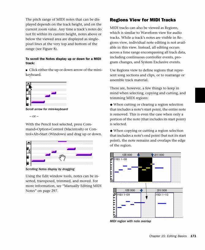
The pitch range of MIDI notes that can be dis-played depends on the track height, and on the current zoom value. Any time a track’s notes do not fit within its current height, notes above or below the viewed area are displayed as single-pixel lines at the very top and bottom of the range (see Figure 8).
To scroll the Notes display up or down for a MIDI track:
■ Click either the up or down arrow of the mini-keyboard.
– or –
With the Pencil tool selected, press Com-mand+Option+Control (Macintosh) or Con-trol+Alt+Start (Windows) and drag up or down.
Using the Edit window tools, notes can be in-serted, transposed, trimmed, and moved. For more information, see “Manually Editing MIDI Notes” on page 297.
Scroll arrow for mini-keyboard
Scrolling Notes display by dragging
Regions View for MIDI Tracks
MIDI tracks can also be viewed as Regions, which is similar to Waveform view for audio tracks. While a track’s notes are visible in Re-gions view, individual note editing is not avail-able in this view. Instead, all editing occurs across a time range encompassing all track data, including continuous controller events, pro-gram changes, and System Exclusive events.
Use Regions view to define regions that repre-sent song sections and clips, or to rearrange or assemble track material.
There are, however, a few things to keep in mind when selecting, copying and cutting, and trimming MIDI regions:
◆ When cutting or clearing a region selection that includes a note’s start point, the entire note is removed. This is even the case when only a portion of the note (that includes its start point) is selected.
◆ When copying or cutting a region selection that includes a note’s end point (but not its start point), the note remains and overlaps the edge of the region.
MIDI region with note overlap
Chapter 15: Editing Basics 171
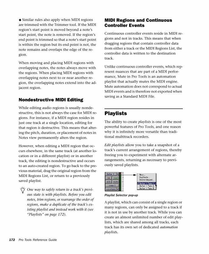
172
◆ Similar rules also apply when MIDI regions are trimmed with the Trimmer tool. If the MIDI region’s start point is moved beyond a note’s start point, the note is removed. If the region’s end point is trimmed so that a note’s start point is within the region but its end point is not, the note remains and overlaps the edge of the re-gion.
When moving and placing MIDI regions with overlapping notes, the notes always move with the regions. When placing MIDI regions with overlapping notes next to or near another re-gion, the overlapping notes extend into the ad-jacent region.
Nondestructive MIDI Editing
While editing audio regions is usually nonde-structive, this is not always the case for MIDI re-gions. For instance, if a MIDI region resides in just one track at a single location, editing for that region is destructive. This means that alter-ing the pitch, duration, or placement of notes in Notes view permanently alters the region.
However, when editing a MIDI region that oc-curs elsewhere, in the same track (at another lo-cation or in a different playlist) or in another track, the editing is nondestructive and occurs to an auto-created region. To go back to the pre-vious material, drag the original region from the MIDI Regions List, or return to a previously saved playlist.
One way to safely return to a track’s previ-ous state is with playlists. Before you edit notes, trim regions, or rearrange the order of regions, make a duplicate of the track’s ex-isting playlist and instead work with it (see “Playlists” on page 172).
Pro Tools Reference Guide
MIDI Regions and Continuous Controller Events
Continuous controller events reside in MIDI re-gions and not in tracks. This means that when dragging regions that contain controller data from either a track or the MIDI Regions List, the controller data is written to the destination track.
Unlike continuous controller events, which rep-resent nuances that are part of a MIDI perfor-mance, Mute in Pro Tools is an automation playlist that actually mutes the MIDI engine. Mute automation does not correspond to actual MIDI events and is therefore not exported when saving as a Standard MIDI File.
PlaylistsThe ability to create playlists is one of the most powerful features of Pro Tools, and one reason why it is infinitely more versatile than tradi-tional multitrack recorders.
Edit playlists allow you to take a snapshot of a track’s current arrangement of regions, thereby freeing you to experiment with alternate ar-rangements, returning as necessary to previ-ously saved playlists.
A playlist, which can consist of a single region or many regions, can only be assigned to a track if it is not in use by another track. While you can create an almost unlimited number of edit play-lists, which are shared among all tracks, each track has its own set of dedicated automation playlists.
Playlist Selector pop-up
Automation playlists for audio tracks store data for volume, pan, mute, and plug-in parameters. Automation playlists for MIDI tracks, however, store only mute information; continuous con-troller events, program changes, and sysex events are stored in MIDI regions and therefore reside within edit playlists.
Playlists and Groups
Playlist functions affect all tracks within an Edit Group (if the group is active). This is useful when you want to switch to new or existing playlists among several tracks.
Working with Playlists
When you add a new track to a session, its play-list is empty until you record or import material to it, or drag a region to it from the Audio or MIDI Regions List.
When you edit a track, you can work with a copy of the track's playlist and keep the original playlist arrangement intact.
To duplicate a track’s current playlist:
1 Click the track’s Playlist Selector and choose Duplicate from the pop-up menu.
2 Enter a name for the new playlist and click OK.
The duplicated playlist appears in the track and the track’s name is changed to the name of the new playlist.
You can also create a new playlist and record or drag regions to it.
To create a new (empty) playlist:
1 Click the track’s Playlist Selector and choose New from the pop-up menu.
2 Enter a name for the new playlist and click OK. An empty playlist with the specified name appears in the track.
As long as a playlist is unassigned, it can be re-called and assigned to any track. Only unas-signed playlists appear in the Playlist Selector pop-up.
To recall and assign a playlist:
■ Click the track’s Playlist Selector and choose the playlist from the pop-up menu.
The selected playlist appears in the track and the track’s name is updated to that of the selected playlist.
Renaming a Playlist
You can rename a playlist by renaming the track to which it is assigned.
To rename a track’s assigned playlist:
1 Double-click the track’s name.
2 Enter a new name and click OK. Both the track and playlist names are updated.
Deleting a Playlist
You can delete a playlist from a session entirely. However, since playlists take almost no disk space, you don’t need to delete them for space reasons.
Chapter 15: Editing Basics 173
174
To delete the current playlist for a track:
1 Click the track’s Playlist Selector and choose Delete Unused from the pop-up menu.
2 Select the unassigned playlists you want to de-lete. Shift-click to select multiple playlists.
3 Click OK to delete the playlists. This operation cannot be undone.
Multiple UndoPro Tools can keep track of up to 16 of the last undoable operations, allowing you to return to a previous editing state.
The Undo operations in Pro Tools are stored in a queue, in the order in which they were invoked. When choosing Edit > Undo, the most recent operation is undone. If you choose Undo again, the next operation in the queue is undone. You can also choose Edit > Redo to redo an opera-tion, which moves back through the Undo queue by one step.
For example, suppose the following operations have been performed, with item 1 being the most recent (first in the queue):
1 Region cut from track
2 Region pasted to track
3 Region slid forward
4 Regions shuffled
5 MIDI note trimmed
6 MIDI note inserted with Pencil
When deleting a track from a session, you have the option of deleting or keeping its playlists, so they can be used on other tracks.
Pro Tools Reference Guide
In this example, to Undo the region shuffle, you would have to choose Edit > Undo four times, which would also Undo the first three opera-tions in the queue.
If you then choose Edit > Redo, followed by an-other edit operation, such as a region trim, the Undo queue would then be:
1 Region trimmed
2 Regions shuffled
3 MIDI note trimmed
4 MIDI note inserted with Pencil
To undo the last operation:
■ Choose Edit > Undo.
– or –
■ Press Command+Z (Macintosh) or Control+Z (Windows).
To redo the last undone operation:
■ Choose Edit > Redo.
– or –
■ Press Shift+Command+Z (Macintosh) or Shift+Control+Z (Windows).
Operations that clear the Undo Queue
There are a number of Pro Tools operations that clear the Undo queue, such as deleting a track or playlist, or clearing a region from the Audio or MID Regions List.
When the Undo queue will be cleared by an op-eration, Pro Tools will warn you.
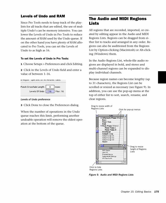
Levels of Undo and RAM
Since Pro Tools needs to keep track of the play-lists for all tracks that are edited, the use of mul-tiple Undo’s can be memory intensive. You can lower the Levels of Undo in Pro Tools to reduce the amount of RAM used by the Undo queue. If on the other hand you have plenty of RAM allo-cated to Pro Tools, you can set the Levels of Undo to as high as 16.
To set the Levels of Undo in Pro Tools:
1 Choose Setups > Preferences and click Editing.
2 Click in the Levels of Undo field and enter a value of between 1–16.
3 Click Done to close the Preferences dialog.
When the number of operations in the Undo queue reaches this limit, performing another undoable operation will remove the oldest oper-ation at the bottom of the queue.
Levels of Undo preference
The Audio and MIDI Regions ListsAll regions that are recorded, imported, or cre-ated by editing appear in the Audio and MIDI Regions Lists. Regions can be dragged from ei-ther list to tracks and arranged in any order. Re-gions can also be auditioned from the Regions List by Option-clicking (Macintosh) or Alt-click-ing (Windows) them.
In the Audio Regions List, whole-file audio re-gions are displayed in bold, and stereo and multi-channel regions can be expanded to dis-play individual channels.
Because region names can become lengthy (up to 31 characters), the Regions List can be scrolled or resized as necessary (see Figure 9). In addition, you can use the pop-up menu at the top of either list to sort, search, rename, and clear regions.
Figure 9. Audio and MIDI Regions Lists
Click to hide Regions Lists
Drag to resize width of Regions Lists
Drag to resize height of Regions Lists
Click for pop-up menus
Chapt
er 15: Editing Basics 175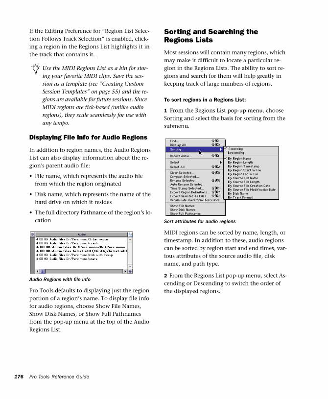
176
If the Editing Preference for “Region List Selec-tion Follows Track Selection” is enabled, click-ing a region in the Regions List highlights it in the track that contains it.
Displaying File Info for Audio Regions
In addition to region names, the Audio Regions List can also display information about the re-gion’s parent audio file:
• File name, which represents the audio file from which the region originated
• Disk name, which represents the name of the hard drive on which it resides
• The full directory Pathname of the region’s lo-cation
Pro Tools defaults to displaying just the region portion of a region’s name. To display file info for audio regions, choose Show File Names, Show Disk Names, or Show Full Pathnames from the pop-up menu at the top of the Audio Regions List.
Use the MIDI Regions List as a bin for stor-ing your favorite MIDI clips. Save the ses-sion as a template (see “Creating Custom Session Templates” on page 55) and the re-gions are available for future sessions. Since MIDI regions are tick-based (unlike audio regions), they scale seamlessly for use with any tempo.
Audio Regions with file info
Pro Tools Reference Guide
Sorting and Searching the Regions Lists
Most sessions will contain many regions, which may make it difficult to locate a particular re-gion in the Regions Lists. The ability to sort re-gions and search for them will help greatly in keeping track of large numbers of regions.
To sort regions in a Regions List:
1 From the Regions List pop-up menu, choose Sorting and select the basis for sorting from the submenu.
MIDI regions can be sorted by name, length, or timestamp. In addition to these, audio regions can be sorted by region start and end times, var-ious attributes of the source audio file, disk name, and path type.
2 From the Regions List pop-up menu, select As-cending or Descending to switch the order of the displayed regions.
Sort attributes for audio regions
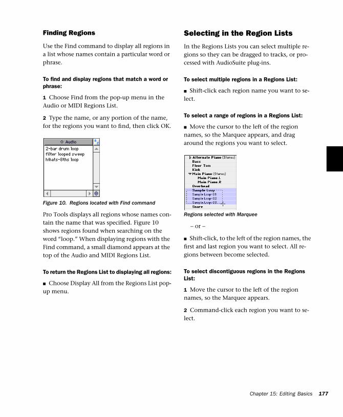
Finding Regions
Use the Find command to display all regions in a list whose names contain a particular word or phrase.
To find and display regions that match a word or phrase:
1 Choose Find from the pop-up menu in the Audio or MIDI Regions List.
2 Type the name, or any portion of the name, for the regions you want to find, then click OK.
Pro Tools displays all regions whose names con-tain the name that was specified. Figure 10 shows regions found when searching on the word “loop.” When displaying regions with the Find command, a small diamond appears at the top of the Audio and MIDI Regions List.
To return the Regions List to displaying all regions:
■ Choose Display All from the Regions List pop-up menu.
Figure 10. Regions located with Find command
Selecting in the Region Lists
In the Regions Lists you can select multiple re-gions so they can be dragged to tracks, or pro-cessed with AudioSuite plug-ins.
To select multiple regions in a Regions List:
■ Shift-click each region name you want to se-lect.
To select a range of regions in a Regions List:
■ Move the cursor to the left of the region names, so the Marquee appears, and drag around the regions you want to select.
– or –
■ Shift-click, to the left of the region names, the first and last region you want to select. All re-gions between become selected.
To select discontiguous regions in the Regions List:
1 Move the cursor to the left of the region names, so the Marquee appears.
2 Command-click each region you want to se-lect.
Regions selected with Marquee
Chapter 15: Editing Basics 177
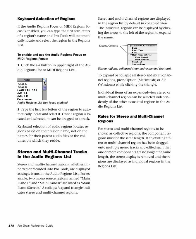
178
Keyboard Selection of Regions
If the Audio Regions Focus or MIDI Regions Fo-cus is enabled, you can type the first few letters of a region’s name and Pro Tools will automati-cally locate and select the region in the Regions List.
To enable and use the Audio Regions Focus or MIDI Regions Focus:
1 Click the a-z button in upper right of the Au-dio Regions List or MIDI Regions List.
2 Type the first few letters of the region to auto-matically locate and select it. Once a region is lo-cated and selected, it can be dragged to a track.
Keyboard selection of audio regions locates re-gions based on their region name, not on the names for their parent audio files or the vol-umes on which they reside.
Stereo and Multi-Channel Tracks in the Audio Regions List
Stereo and multi-channel regions, whether im-ported or recorded into Pro Tools, are displayed as single items in the Audio Regions List. For ex-ample, two mono source regions named “Main Piano.L” and “Main Piano.R” are listed as “Main Piano (Stereo).” A collapse/expand triangle indi-cates stereo and multi-channel regions.
Audio Regions List Key focus enabled
Pro Tools Reference Guide
Stereo and multi-channel regions are displayed in the region list by default in collapsed view. The individual regions can be displayed by click-ing the arrow to the left of the region to expand the name.
To expand or collapse all stereo and multi-chan-nel regions, press Option (Macintosh) or Alt (Windows) while clicking the triangle.
Individual items of an expanded-view stereo or multi-channel region can be selected indepen-dently of the other associated regions in the Au-dio Regions List.
Rules for Stereo and Multi-Channel Regions
For stereo and multi-channel regions to be shown as collective regions, the component re-gions must be the same length. If an existing ste-reo or multi-channel region has been dragged onto multiple mono tracks and edited such that one or more components are no longer the same length, the stereo display is removed and the re-gions are displayed as individual regions in the Regions List.
Stereo regions, collapsed (top) and expanded (bottom).
Expand/Collapse

Edit ModesPro Tools has four Edit modes: Shuffle, Spot, Slip, and Grid. The Edit mode is selected by clicking the desired button in the upper left of the Edit window.
The Edit mode affects the movement and place-ment of audio and MIDI regions (and individual MIDI notes), how commands like Copy and Paste function, and also how the various edit tools (Trimmer, Selector, Grabber, and Pencil) work.
Shuffle
In Shuffle mode, you can move regions freely within a track or to other tracks, but their move-ment is constrained by other regions. That is, if you place several regions in a track, they auto-matically snap to each other. You can then “shuffle” their order, but you cannot separate them from each other and you cannot make them overlap as in Slip mode. In Shuffle mode, adding another region to the beginning of a track moves all subsequent regions to the right by the length of the region added.
When using the Trimmer in Shuffle mode, changing a region’s start or end point automat-ically moves the adjacent regions as necessary. The placement and insertion of MIDI notes is not affected by Shuffle mode.
Edit mode buttons
You can also use F1 (Shuffle), F2 (Slip), F3 (Spot), and F4 (Grid) to set the Edit mode.
Slip
In Slip mode, regions can be moved freely within a track or to other tracks. In this mode it is possible to place a region so that there is space between it and other regions in a track. When the track is played back, this space is silent. It is also possible to move a region so that it overlaps or completely covers another region.
Use Slip mode when you want the Trimmer, Se-lector, Grabber, and Pencil tools to work with-out any restrictions to placement in time.
Spot
Use Spot mode to place regions at precise loca-tions. This can be particularly useful when per-forming post production tasks around SMPTE frame locations. In this mode you can specify a frame location (or a location based on any of the other time formats), capture an incoming Time Code address, or use a region’s time stamps as reference points for spotting.
In Spot mode, when you move or trim regions, the Spot dialog opens.
Grid
In Grid mode, regions and MIDI notes that are moved or inserted “snap” to a user-definable time grid. In addition to placing material cleanly on the beat, Grid mode is also useful for making precise Edit and Timeline selections.
The actual grid size, chosen from the Grid Value pop-up in the upper right of the Edit window, can be based on a time value using the Main Time Scale; or, if Follow Main Time Scale is de-selected, another time format can be used for the grid size.
NOTE: The current Grid Value is also used for the Quantize Regions Command.
Chapter 15: Editing Basics 179
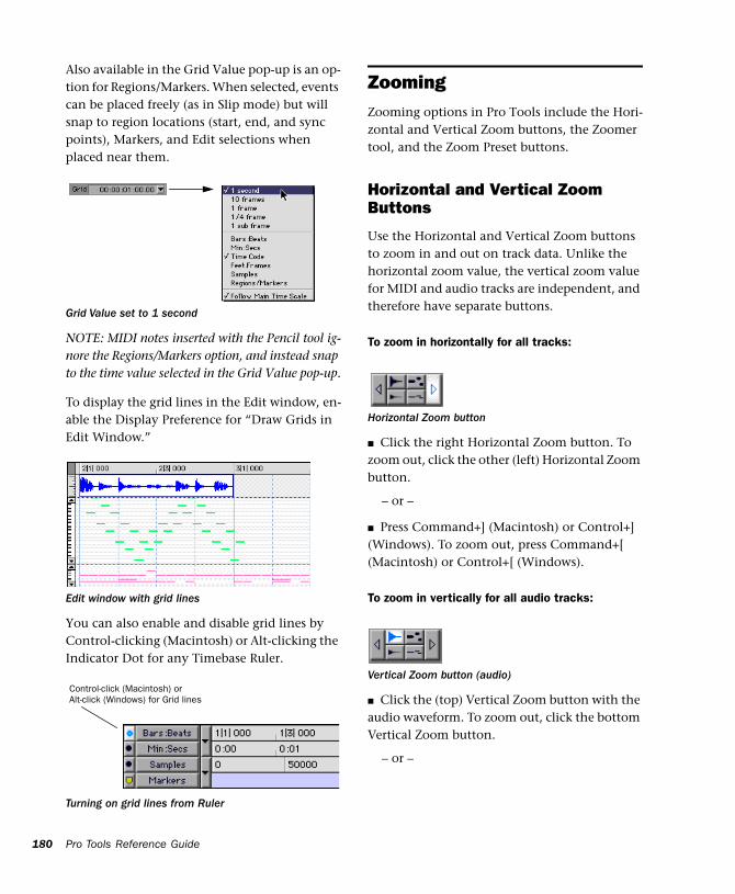
180
Also available in the Grid Value pop-up is an op-tion for Regions/Markers. When selected, events can be placed freely (as in Slip mode) but will snap to region locations (start, end, and sync points), Markers, and Edit selections when placed near them.
NOTE: MIDI notes inserted with the Pencil tool ig-nore the Regions/Markers option, and instead snap to the time value selected in the Grid Value pop-up.
To display the grid lines in the Edit window, en-able the Display Preference for “Draw Grids in Edit Window.”
You can also enable and disable grid lines by Control-clicking (Macintosh) or Alt-clicking the Indicator Dot for any Timebase Ruler.
Grid Value set to 1 second
Edit window with grid lines
Turning on grid lines from Ruler
Control-click (Macintosh) or Alt-click (Windows) for Grid lines
Pro Tools Reference Guide
ZoomingZooming options in Pro Tools include the Hori-zontal and Vertical Zoom buttons, the Zoomer tool, and the Zoom Preset buttons.
Horizontal and Vertical Zoom Buttons
Use the Horizontal and Vertical Zoom buttons to zoom in and out on track data. Unlike the horizontal zoom value, the vertical zoom value for MIDI and audio tracks are independent, and therefore have separate buttons.
To zoom in horizontally for all tracks:
■ Click the right Horizontal Zoom button. To zoom out, click the other (left) Horizontal Zoom button.
– or –
■ Press Command+] (Macintosh) or Control+] (Windows). To zoom out, press Command+[ (Macintosh) or Control+[ (Windows).
To zoom in vertically for all audio tracks:
■ Click the (top) Vertical Zoom button with the audio waveform. To zoom out, click the bottom Vertical Zoom button.
– or –
Horizontal Zoom button
Vertical Zoom button (audio)
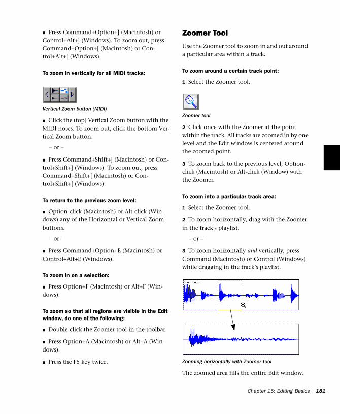
■ Press Command+Option+] (Macintosh) or Control+Alt+] (Windows). To zoom out, press Command+Option+[ (Macintosh) or Con-trol+Alt+[ (Windows).
To zoom in vertically for all MIDI tracks:
■ Click the (top) Vertical Zoom button with the MIDI notes. To zoom out, click the bottom Ver-tical Zoom button.
– or –
■ Press Command+Shift+] (Macintosh) or Con-trol+Shift+] (Windows). To zoom out, press Command+Shift+[ (Macintosh) or Con-trol+Shift+[ (Windows).
To return to the previous zoom level:
■ Option-click (Macintosh) or Alt-click (Win-dows) any of the Horizontal or Vertical Zoom buttons.
– or –
■ Press Command+Option+E (Macintosh) or Control+Alt+E (Windows).
To zoom in on a selection:
■ Press Option+F (Macintosh) or Alt+F (Win-dows).
To zoom so that all regions are visible in the Edit window, do one of the following:
■ Double-click the Zoomer tool in the toolbar.
■ Press Option+A (Macintosh) or Alt+A (Win-dows).
■ Press the F5 key twice.
Vertical Zoom button (MIDI)
Zoomer Tool
Use the Zoomer tool to zoom in and out around a particular area within a track.
To zoom around a certain track point:
1 Select the Zoomer tool.
2 Click once with the Zoomer at the point within the track. All tracks are zoomed in by one level and the Edit window is centered around the zoomed point.
3 To zoom back to the previous level, Option-click (Macintosh) or Alt-click (Window) with the Zoomer.
To zoom into a particular track area:
1 Select the Zoomer tool.
2 To zoom horizontally, drag with the Zoomer in the track’s playlist.
– or –
3 To zoom horizontally and vertically, press Command (Macintosh) or Control (Windows) while dragging in the track’s playlist.
The zoomed area fills the entire Edit window.
Zoomer tool
Zooming horizontally with Zoomer tool
Chapter 15: Editing Basics 181
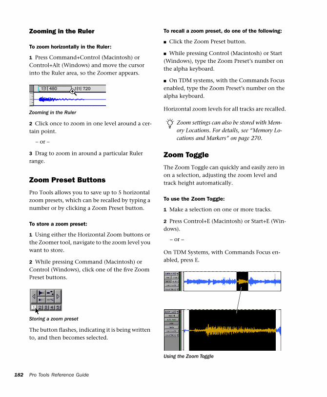
182
Zooming in the Ruler
To zoom horizontally in the Ruler:
1 Press Command+Control (Macintosh) or Control+Alt (Windows) and move the cursor into the Ruler area, so the Zoomer appears.
2 Click once to zoom in one level around a cer-tain point.
– or –
3 Drag to zoom in around a particular Ruler range.
Zoom Preset Buttons
Pro Tools allows you to save up to 5 horizontal zoom presets, which can be recalled by typing a number or by clicking a Zoom Preset button.
To store a zoom preset:
1 Using either the Horizontal Zoom buttons or the Zoomer tool, navigate to the zoom level you want to store.
2 While pressing Command (Macintosh) or Control (Windows), click one of the five Zoom Preset buttons.
The button flashes, indicating it is being written to, and then becomes selected.
Zooming in the Ruler
Storing a zoom preset
Pro Tools Reference Guide
To recall a zoom preset, do one of the following:
■ Click the Zoom Preset button.
■ While pressing Control (Macintosh) or Start (Windows), type the Zoom Preset’s number on the alpha keyboard.
■ On TDM systems, with the Commands Focus enabled, type the Zoom Preset’s number on the alpha keyboard.
Horizontal zoom levels for all tracks are recalled.
Zoom Toggle
The Zoom Toggle can quickly and easily zero in on a selection, adjusting the zoom level and track height automatically.
To use the Zoom Toggle:
1 Make a selection on one or more tracks.
2 Press Control+E (Macintosh) or Start+E (Win-dows).
– or –
On TDM Systems, with Commands Focus en-abled, press E.
Zoom settings can also be stored with Mem-ory Locations. For details, see “Memory Lo-cations and Markers” on page 270.
Using the Zoom Toggle
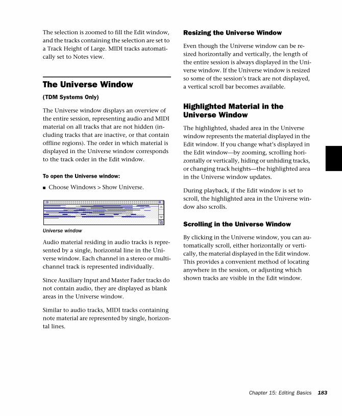
The selection is zoomed to fill the Edit window, and the tracks containing the selection are set to a Track Height of Large. MIDI tracks automati-cally set to Notes view.
The Universe Window(TDM Systems Only)
The Universe window displays an overview of the entire session, representing audio and MIDI material on all tracks that are not hidden (in-cluding tracks that are inactive, or that contain offline regions). The order in which material is displayed in the Universe window corresponds to the track order in the Edit window.
To open the Universe window:
■ Choose Windows > Show Universe.
Audio material residing in audio tracks is repre-sented by a single, horizontal line in the Uni-verse window. Each channel in a stereo or multi-channel track is represented individually.
Since Auxiliary Input and Master Fader tracks do not contain audio, they are displayed as blank areas in the Universe window.
Similar to audio tracks, MIDI tracks containing note material are represented by single, horizon-tal lines.
Universe window
Resizing the Universe Window
Even though the Universe window can be re-sized horizontally and vertically, the length of the entire session is always displayed in the Uni-verse window. If the Universe window is resized so some of the session’s track are not displayed, a vertical scroll bar becomes available.
Highlighted Material in the Universe Window
The highlighted, shaded area in the Universe window represents the material displayed in the Edit window. If you change what’s displayed in the Edit window—by zooming, scrolling hori-zontally or vertically, hiding or unhiding tracks, or changing track heights—the highlighted area in the Universe window updates.
During playback, if the Edit window is set to scroll, the highlighted area in the Universe win-dow also scrolls.
Scrolling in the Universe Window
By clicking in the Universe window, you can au-tomatically scroll, either horizontally or verti-cally, the material displayed in the Edit window. This provides a convenient method of locating anywhere in the session, or adjusting which shown tracks are visible in the Edit window.
Chapter 15: Editing Basics 183
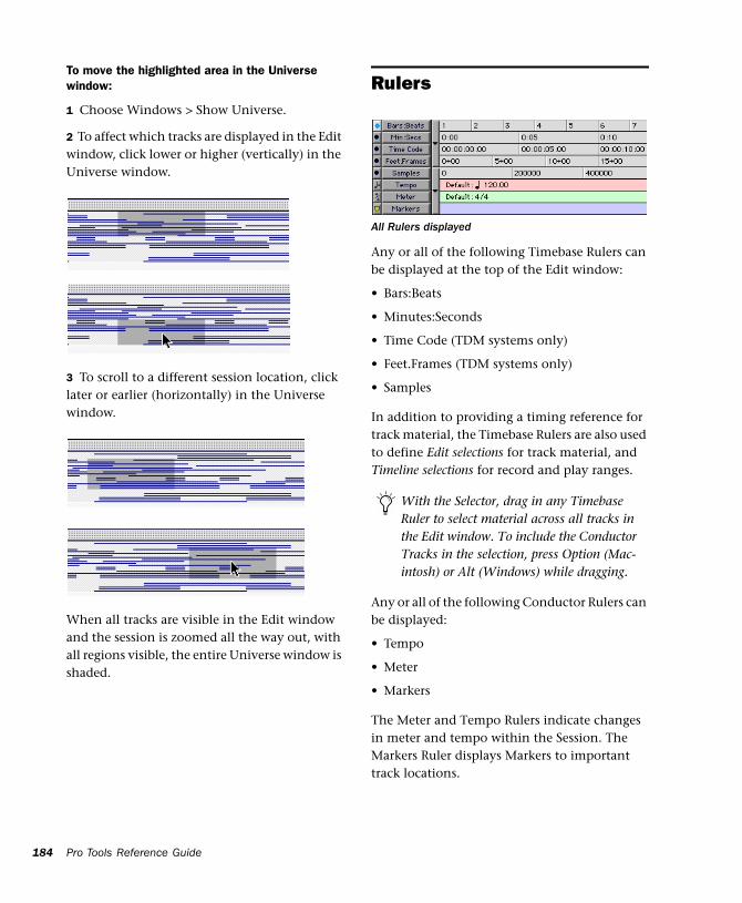
184
To move the highlighted area in the Universe window:
1 Choose Windows > Show Universe.
2 To affect which tracks are displayed in the Edit window, click lower or higher (vertically) in the Universe window.
3 To scroll to a different session location, click later or earlier (horizontally) in the Universe window.
When all tracks are visible in the Edit window and the session is zoomed all the way out, with all regions visible, the entire Universe window is shaded.
Pro Tools Reference Guide
Rulers
Any or all of the following Timebase Rulers can be displayed at the top of the Edit window:
• Bars:Beats
• Minutes:Seconds
• Time Code (TDM systems only)
• Feet.Frames (TDM systems only)
• Samples
In addition to providing a timing reference for track material, the Timebase Rulers are also used to define Edit selections for track material, and Timeline selections for record and play ranges.
Any or all of the following Conductor Rulers can be displayed:
• Tempo
• Meter
• Markers
The Meter and Tempo Rulers indicate changes in meter and tempo within the Session. The Markers Ruler displays Markers to important track locations.
All Rulers displayed
With the Selector, drag in any Timebase Ruler to select material across all tracks in the Edit window. To include the Conductor Tracks in the selection, press Option (Mac-intosh) or Alt (Windows) while dragging.
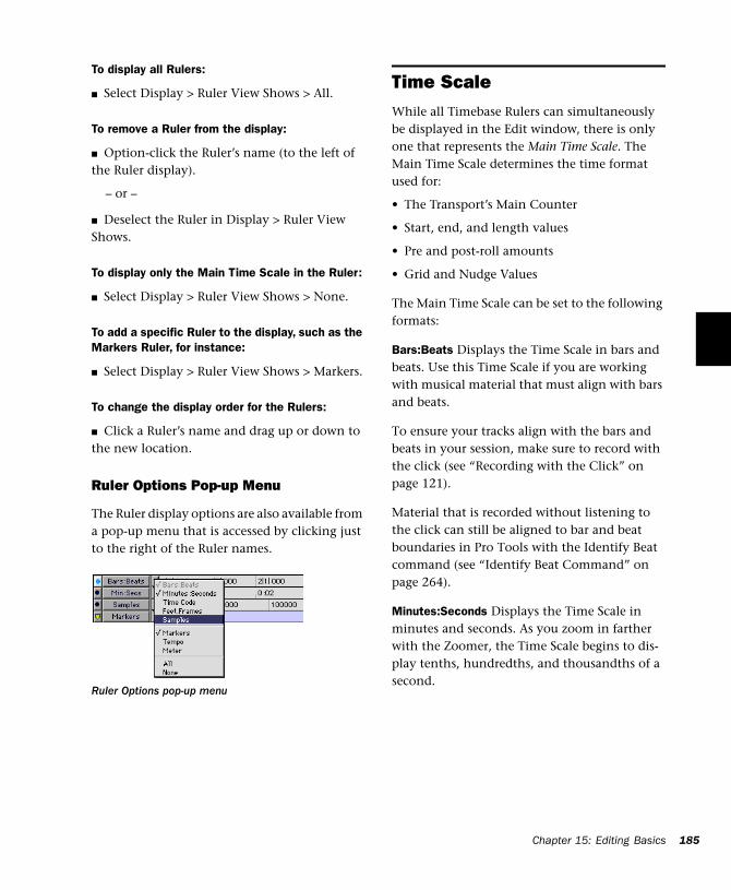
To display all Rulers:
■ Select Display > Ruler View Shows > All.
To remove a Ruler from the display:
■ Option-click the Ruler’s name (to the left of the Ruler display).
– or –
■ Deselect the Ruler in Display > Ruler View Shows.
To display only the Main Time Scale in the Ruler:
■ Select Display > Ruler View Shows > None.
To add a specific Ruler to the display, such as the Markers Ruler, for instance:
■ Select Display > Ruler View Shows > Markers.
To change the display order for the Rulers:
■ Click a Ruler’s name and drag up or down to the new location.
Ruler Options Pop-up Menu
The Ruler display options are also available from a pop-up menu that is accessed by clicking just to the right of the Ruler names.
Ruler Options pop-up menu
Time ScaleWhile all Timebase Rulers can simultaneously be displayed in the Edit window, there is only one that represents the Main Time Scale. The Main Time Scale determines the time format used for:
• The Transport’s Main Counter
• Start, end, and length values
• Pre and post-roll amounts
• Grid and Nudge Values
The Main Time Scale can be set to the following formats:
Bars:Beats Displays the Time Scale in bars and beats. Use this Time Scale if you are working with musical material that must align with bars and beats.
To ensure your tracks align with the bars and beats in your session, make sure to record with the click (see “Recording with the Click” on page 121).
Material that is recorded without listening to the click can still be aligned to bar and beat boundaries in Pro Tools with the Identify Beat command (see “Identify Beat Command” on page 264).
Minutes:Seconds Displays the Time Scale in minutes and seconds. As you zoom in farther with the Zoomer, the Time Scale begins to dis-play tenths, hundredths, and thousandths of a second.
Chapter 15: Editing Basics 185
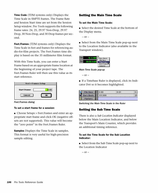
186
Time Code (TDM systems only) Displays the Time Scale in SMPTE frames. The Frame Rate and Session Start time are set from the Session Setup window. Pro Tools supports the following frame rates: 24, 25, 29.97 Non-Drop, 29.97 Drop, 30 Non-Drop, and 30 Drop frames per sec-ond.
Feet.Frames (TDM systems only) Displays the Time Scale in feet and frames for referencing au-dio-for-film projects. The Feet.Frames time dis-play is based on the 35 millimeter film format.
With this Time Scale, you can enter a Start Frame based on an appropriate frame location at the beginning of your project tape. The Feet.Frames Ruler will then use this value as its start reference.
To set a start frame for a session:
■ Choose Setups > Feet.Frames and enter an ap-propriate start frame and click OK (negative off-sets are not supported). This value will become the “zero point” in the Feet.Frames Ruler.
Samples Displays the Time Scale in samples. This format is very useful for high-precision sample editing.
Feet.Frames dialog
Pro Tools Reference Guide
Setting the Main Time Scale
To set the Main Time Scale:
■ Select the desired Time Scale at the bottom of the Display menu.
– or –
■ Select from the Main Time Scale pop-up next to the Location Indicator (also available in the Transport window).
– or –
■ If a Timebase Ruler is displayed, click its Indi-cator Dot so it becomes highlighted.
Setting the Sub Time Scale
There is also a Sub Location Indicator displayed below the Main Location Indicator, and below the Transport’s Main Counter, which provides an additional timing reference.
To set the Time Scale for the Sub Location Indicator:
■ Select from the Sub Time Scale pop-up next to the Location Indicator
– or –
Main Time Scale pop-up
Switching the Main Time Scale in the Ruler
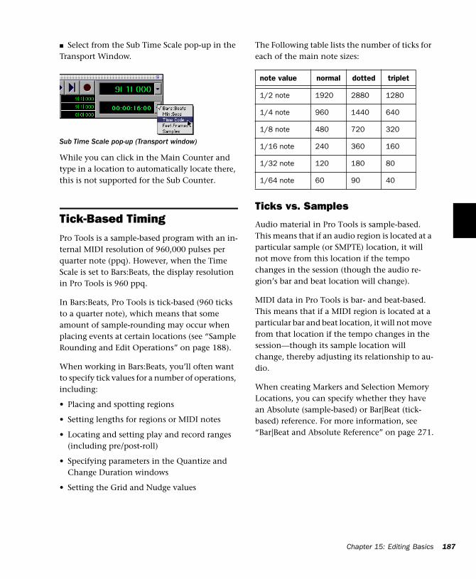
■ Select from the Sub Time Scale pop-up in the Transport Window.
While you can click in the Main Counter and type in a location to automatically locate there, this is not supported for the Sub Counter.
Tick-Based TimingPro Tools is a sample-based program with an in-ternal MIDI resolution of 960,000 pulses per quarter note (ppq). However, when the Time Scale is set to Bars:Beats, the display resolution in Pro Tools is 960 ppq.
In Bars:Beats, Pro Tools is tick-based (960 ticks to a quarter note), which means that some amount of sample-rounding may occur when placing events at certain locations (see “Sample Rounding and Edit Operations” on page 188).
When working in Bars:Beats, you’ll often want to specify tick values for a number of operations, including:
• Placing and spotting regions
• Setting lengths for regions or MIDI notes
• Locating and setting play and record ranges (including pre/post-roll)
• Specifying parameters in the Quantize and Change Duration windows
• Setting the Grid and Nudge values
Sub Time Scale pop-up (Transport window)
The Following table lists the number of ticks for each of the main note sizes:
Ticks vs. Samples
Audio material in Pro Tools is sample-based. This means that if an audio region is located at a particular sample (or SMPTE) location, it will not move from this location if the tempo changes in the session (though the audio re-gion’s bar and beat location will change).
MIDI data in Pro Tools is bar- and beat-based. This means that if a MIDI region is located at a particular bar and beat location, it will not move from that location if the tempo changes in the session—though its sample location will change, thereby adjusting its relationship to au-dio.
When creating Markers and Selection Memory Locations, you can specify whether they have an Absolute (sample-based) or Bar|Beat (tick-based) reference. For more information, see “Bar|Beat and Absolute Reference” on page 271.
note value normal dotted triplet
1/2 note 1920 2880 1280
1/4 note 960 1440 640
1/8 note 480 720 320
1/16 note 240 360 160
1/32 note 120 180 80
1/64 note 60 90 40
Chapter 15: Editing Basics 187
188
Sample Rounding and Edit Operations
Because audio material in Pro Tools is sample-based, some amount of sample-rounding may occur with some edits when the Main Time Scale is set to Bars:Beats. This is most evident when you need audio regions to fall cleanly on the beat (as when looping) and notice that the material is sometimes a tick or two off. With a few simple precautions, this can be avoided.
When selecting audio regions to be copied, du-plicated, or repeated, make sure to select the ma-terial with the Selector (enable Grid Mode for precise selections), or set the selection range by typing in the start and end points in the Event Edit area. Do not select the material with the Grabber (or by double-clicking with the Selec-tor). This ensures that the selection will be pre-cise in terms of bars and beats (and not based on the length of the material in samples).
Pro Tools Reference Guide
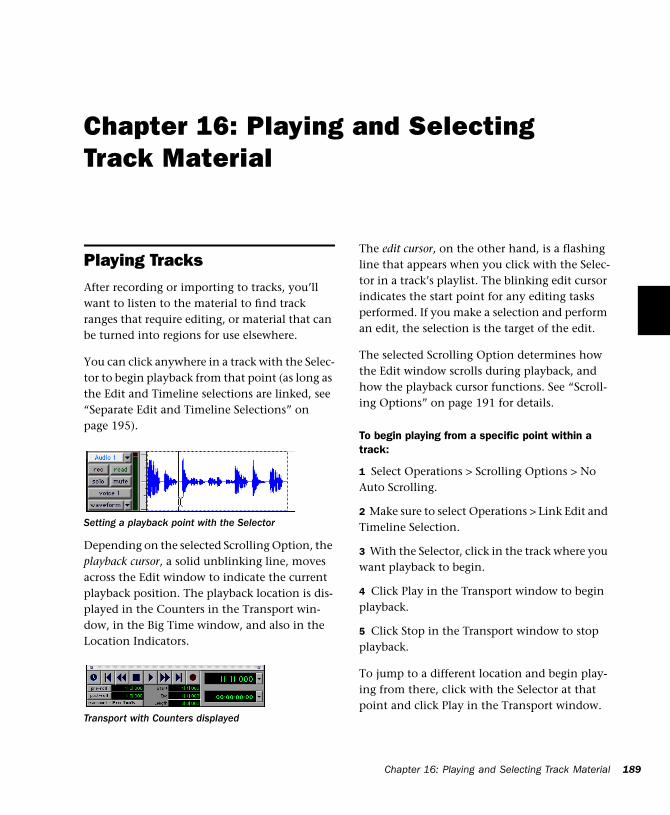
Chapter 16: Playing and Selecting Track Material
Playing TracksAfter recording or importing to tracks, you’ll want to listen to the material to find track ranges that require editing, or material that can be turned into regions for use elsewhere.
You can click anywhere in a track with the Selec-tor to begin playback from that point (as long as the Edit and Timeline selections are linked, see “Separate Edit and Timeline Selections” on page 195).
Depending on the selected Scrolling Option, the playback cursor, a solid unblinking line, moves across the Edit window to indicate the current playback position. The playback location is dis-played in the Counters in the Transport win-dow, in the Big Time window, and also in the Location Indicators.
Setting a playback point with the Selector
Transport with Counters displayed
The edit cursor, on the other hand, is a flashing line that appears when you click with the Selec-tor in a track’s playlist. The blinking edit cursor indicates the start point for any editing tasks performed. If you make a selection and perform an edit, the selection is the target of the edit.
The selected Scrolling Option determines how the Edit window scrolls during playback, and how the playback cursor functions. See “Scroll-ing Options” on page 191 for details.
To begin playing from a specific point within a track:
1 Select Operations > Scrolling Options > No Auto Scrolling.
2 Make sure to select Operations > Link Edit and Timeline Selection.
3 With the Selector, click in the track where you want playback to begin.
4 Click Play in the Transport window to begin playback.
5 Click Stop in the Transport window to stop playback.
To jump to a different location and begin play-ing from there, click with the Selector at that point and click Play in the Transport window.
Chapter 16: Playing and Selecting Track Material 189
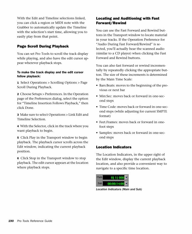
190
With the Edit and Timeline selections linked, you can click a region or MIDI note with the Grabber to automatically update the Timeline with the selection’s start time, allowing you to easily play from that point.
Page Scroll During Playback
You can set Pro Tools to scroll the track display while playing, and also have the edit cursor ap-pear wherever playback stops.
To make the track display and the edit cursor follow playback:
1 Select Operations > Scrolling Options > Page Scroll During Playback.
2 Choose Setups > Preferences. In the Operation page of the Preferences dialog, select the option for “Timeline Insertion Follows Playback,” then click Done.
3 Make sure to select Operations > Link Edit and Timeline Selection.
4 With the Selector, click in the track where you want playback to begin.
5 Click Play in the Transport window to begin playback. The playback cursor scrolls across the Edit window, indicating the current playback position.
6 Click Stop in the Transport window to stop playback. The edit cursor appears at the location where playback stops.
Pro Tools Reference Guide
Locating and Auditioning with Fast Forward/Rewind
You can use the Fast Forward and Rewind but-tons in the Transport window to locate material in your tracks. If the Operation Preference for “Audio During Fast Forward/Rewind” is se-lected, you’ll actually hear the scanned audio (similar to a CD player) when clicking the Fast Forward and Rewind buttons.
You can also fast forward or rewind incremen-tally by repeatedly clicking the appropriate but-ton. The size of these increments is determined by the Main Time Scale:
• Bars:Beats: moves to the beginning of the pre-vious or next bar
• Min:Sec: moves back or forward in one-sec-ond steps
• Time Code: moves back or forward in one-sec-ond steps (while adjusting for current SMPTE format)
• Feet.Frames: moves back or forward in one-foot steps
• Samples: moves back or forward in one-sec-ond steps
Location Indicators
The Location Indicators, in the upper right of the Edit window, display the current playback location, and also provide a convenient way to navigate to a specific time location.
Location Indicators (Main and Sub)
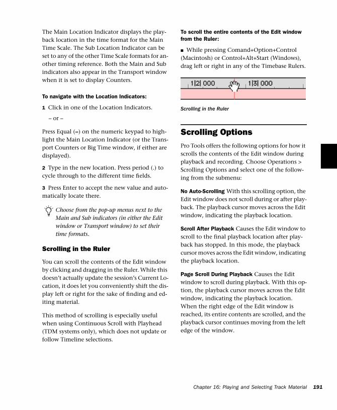
The Main Location Indicator displays the play-back location in the time format for the Main Time Scale. The Sub Location Indicator can be set to any of the other Time Scale formats for an-other timing reference. Both the Main and Sub indicators also appear in the Transport window when it is set to display Counters.
To navigate with the Location Indicators:
1 Click in one of the Location Indicators.
– or –
Press Equal (=) on the numeric keypad to high-light the Main Location Indicator (or the Trans-port Counters or Big Time window, if either are displayed).
2 Type in the new location. Press period (.) to cycle through to the different time fields.
3 Press Enter to accept the new value and auto-matically locate there.
Scrolling in the Ruler
You can scroll the contents of the Edit window by clicking and dragging in the Ruler. While this doesn’t actually update the session’s Current Lo-cation, it does let you conveniently shift the dis-play left or right for the sake of finding and ed-iting material.
This method of scrolling is especially useful when using Continuous Scroll with Playhead (TDM systems only), which does not update or follow Timeline selections.
Choose from the pop-up menus next to the Main and Sub indicators (in either the Edit window or Transport window) to set their time formats.
To scroll the entire contents of the Edit window from the Ruler:
■ While pressing Comand+Option+Control (Macintosh) or Control+Alt+Start (Windows), drag left or right in any of the Timebase Rulers.
Scrolling OptionsPro Tools offers the following options for how it scrolls the contents of the Edit window during playback and recording. Choose Operations > Scrolling Options and select one of the follow-ing from the submenu:
No Auto-Scrolling With this scrolling option, the Edit window does not scroll during or after play-back. The playback cursor moves across the Edit window, indicating the playback location.
Scroll After Playback Causes the Edit window to scroll to the final playback location after play-back has stopped. In this mode, the playback cursor moves across the Edit window, indicating the playback location.
Page Scroll During Playback Causes the Edit window to scroll during playback. With this op-tion, the playback cursor moves across the Edit window, indicating the playback location. When the right edge of the Edit window is reached, its entire contents are scrolled, and the playback cursor continues moving from the left edge of the window.
Scrolling in the Ruler
Chapter 16: Playing and Selecting Track Material 191
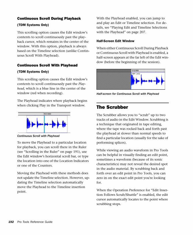
192
Continuous Scroll During Playback
(TDM Systems Only)
This scrolling option causes the Edit window’s contents to scroll continuously past the play-back cursor, which remains in the center of the window. With this option, playback is always based on the Timeline selection (unlike Contin-uous Scroll With Playhead).
Continuous Scroll With Playhead
(TDM Systems Only)
This scrolling option causes the Edit window’s contents to scroll continuously past the Play-head, which is a blue line in the center of the window (red when recording).
The Playhead indicates where playback begins when clicking Play in the Transport window.
To move the Playhead to a particular location for playback, you can scroll there in the Ruler (see “Scrolling in the Ruler” on page 191), use the Edit window’s horizontal scroll bar, or type the location into one of the Location Indicators or one of the Counters.
Moving the Playhead with these methods does not update the Timeline selection. However, up-dating the Timeline selection automatically move the Playhead to the Timeline insertion point.
Continuous Scroll with Playhead
Pro Tools Reference Guide
With the Playhead enabled, you can jump to and play an Edit or Timeline selection. For de-tails, see “Playing Edit and Timeline Selections with the Playhead” on page 207.
Half-Screen Edit Window
When either Continuous Scroll During Playback or Continuous Scroll with Playhead is enabled, a half-screen appears at the far left of the Edit win-dow (before the beginning of the session).
The ScrubberThe Scrubber allows you to “scrub” up to two tracks of audio in the Edit Window. Scrubbing is a technique that originated in tape editing, where the tape was rocked back and forth past the playhead at slower than normal speeds to find a particular location (usually for the sake of performing splices).
While viewing an audio waveform in Pro Tools can be helpful in visually finding an edit point, sometimes a waveform (because of its sonic characteristics) may not reveal the desired spot in the audio material. By scrubbing back and forth over an edit point in Pro Tools, you can zero in on the exact edit point you're looking for.
When the Operation Preference for “Edit Inser-tion Follows Scrub/Shuttle” is enabled, the edit cursor automatically locates to the point where scrubbing stops.
Half-screen for Continuous Scroll with Playhead

When the Scrolling Option is set to Continuous Scroll During Playback or Continuous Scroll with Playhead, clicking with the Scrubber in a track’s playlist centers the Edit window around that point, and moves the Playhead there. With these Scrolling Options, scrubbed material moves past the Playhead, which remains sta-tionary and centered.
NOTE: Scrubbing is only supported for audio tracks. MIDI tracks cannot be scrubbed.
To scrub a single audio track:
1 With the Scrubber selected, drag within the track—left for reverse, right for forward.
The distance and speed with which you drag (with either the mouse, or an external MIDI controller wheel) determine the length and speed of the scrubbed audio. Audio from the scrubbed track is routed to its output, along with any effects assigned to the track.
The resolution for the Scrubber is dependent upon the zoom factor for the scrubbed track. For finer resolutions without zooming, press Com-mand (Macintosh) or Control (Windows) while scrubbing.
Scrubbing an audio track with the Scrubber
You can temporarily switch the Selector to the Scrubber by Control-clicking (Macin-tosh) or Right-clicking (Windows). For finer resolution, Command-Control-click (Mac-intosh) or Control-Right-click (Windows).
To scrub up to two audio tracks:
■ With the Scrubber selected, drag between two adjacent tracks.
– or –
■ Scrub within a selection that contains multi-ple tracks. Only the first two tracks are heard.
Scrub/Shuttle Mode
When scrubbing normally, you can scrub at nor-mal playback speeds or slower. Scrub/Shuttle mode, however, lets you scrub at several times normal speed, which is helpful in playing through large ranges and locating material.
To scrub in Shuttle mode (at several times normal speed):
1 Select the Scrubber tool.
2 While pressing Option (Macintosh) or Alt (Windows), drag within the track—left for re-verse, right for forward.The Fast Forward and Rewind buttons in the Transport window en-gage.
The distance and speed dragged determine the speed for the scrubbed audio.
Scrubbing between two audio tracks
The maximum number of channels scrubbed in Pro Tools is eight, which would enable you to scrub two stereo tracks (four channels), but not two 5.1 surround tracks (12 channels).
Chapter 16: Playing and Selecting Track Material 193
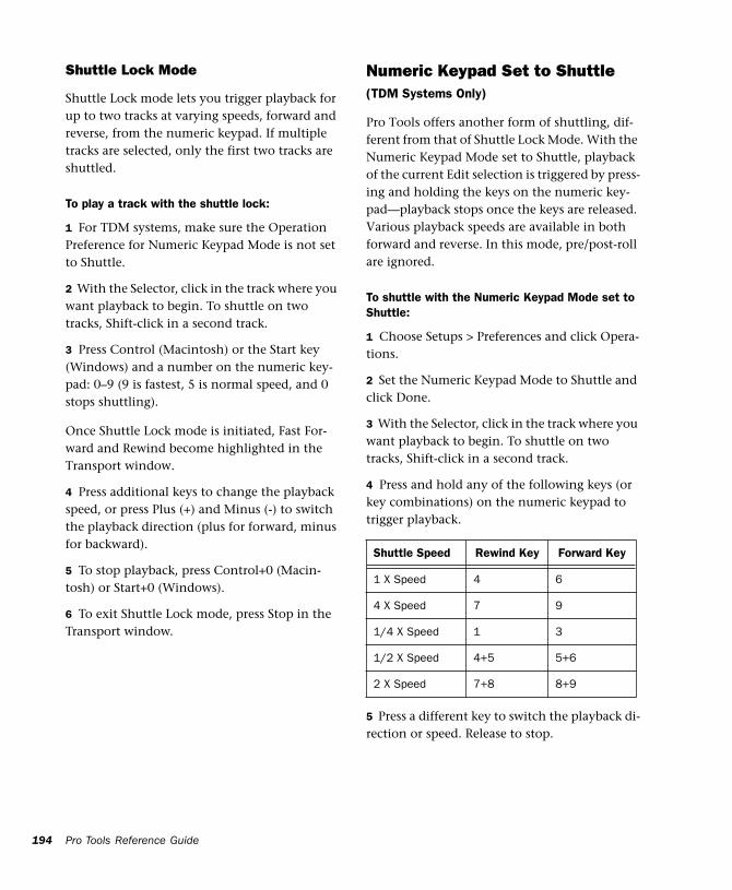
194
Shuttle Lock Mode
Shuttle Lock mode lets you trigger playback for up to two tracks at varying speeds, forward and reverse, from the numeric keypad. If multiple tracks are selected, only the first two tracks are shuttled.
To play a track with the shuttle lock:
1 For TDM systems, make sure the Operation Preference for Numeric Keypad Mode is not set to Shuttle.
2 With the Selector, click in the track where you want playback to begin. To shuttle on two tracks, Shift-click in a second track.
3 Press Control (Macintosh) or the Start key (Windows) and a number on the numeric key-pad: 0–9 (9 is fastest, 5 is normal speed, and 0 stops shuttling).
Once Shuttle Lock mode is initiated, Fast For-ward and Rewind become highlighted in the Transport window.
4 Press additional keys to change the playback speed, or press Plus (+) and Minus (-) to switch the playback direction (plus for forward, minus for backward).
5 To stop playback, press Control+0 (Macin-tosh) or Start+0 (Windows).
6 To exit Shuttle Lock mode, press Stop in the Transport window.
Pro Tools Reference Guide
Numeric Keypad Set to Shuttle(TDM Systems Only)
Pro Tools offers another form of shuttling, dif-ferent from that of Shuttle Lock Mode. With the Numeric Keypad Mode set to Shuttle, playback of the current Edit selection is triggered by press-ing and holding the keys on the numeric key-pad—playback stops once the keys are released. Various playback speeds are available in both forward and reverse. In this mode, pre/post-roll are ignored.
To shuttle with the Numeric Keypad Mode set to Shuttle:
1 Choose Setups > Preferences and click Opera-tions.
2 Set the Numeric Keypad Mode to Shuttle and click Done.
3 With the Selector, click in the track where you want playback to begin. To shuttle on two tracks, Shift-click in a second track.
4 Press and hold any of the following keys (or key combinations) on the numeric keypad to trigger playback.
5 Press a different key to switch the playback di-rection or speed. Release to stop.
Shuttle Speed Rewind Key Forward Key
1 X Speed 4 6
4 X Speed 7 9
1/4 X Speed 1 3
1/2 X Speed 4+5 5+6
2 X Speed 7+8 8+9
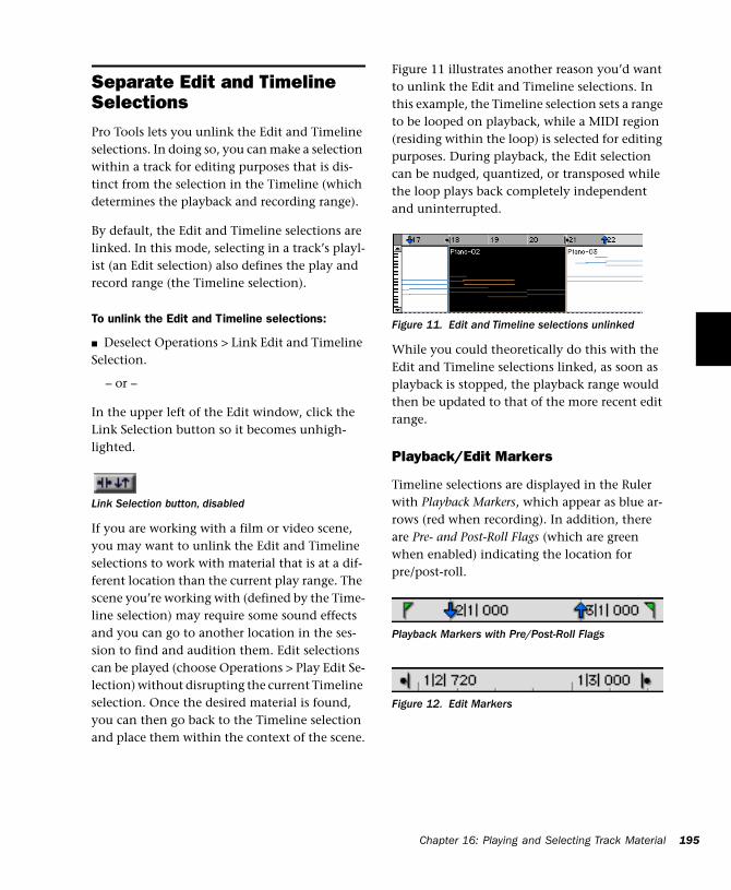
Separate Edit and Timeline SelectionsPro Tools lets you unlink the Edit and Timeline selections. In doing so, you can make a selection within a track for editing purposes that is dis-tinct from the selection in the Timeline (which determines the playback and recording range).
By default, the Edit and Timeline selections are linked. In this mode, selecting in a track’s playl-ist (an Edit selection) also defines the play and record range (the Timeline selection).
To unlink the Edit and Timeline selections:
■ Deselect Operations > Link Edit and Timeline Selection.
– or –
In the upper left of the Edit window, click the Link Selection button so it becomes unhigh-lighted.
If you are working with a film or video scene, you may want to unlink the Edit and Timeline selections to work with material that is at a dif-ferent location than the current play range. The scene you’re working with (defined by the Time-line selection) may require some sound effects and you can go to another location in the ses-sion to find and audition them. Edit selections can be played (choose Operations > Play Edit Se-lection) without disrupting the current Timeline selection. Once the desired material is found, you can then go back to the Timeline selection and place them within the context of the scene.
Link Selection button, disabled
Figure 11 illustrates another reason you’d want to unlink the Edit and Timeline selections. In this example, the Timeline selection sets a range to be looped on playback, while a MIDI region (residing within the loop) is selected for editing purposes. During playback, the Edit selection can be nudged, quantized, or transposed while the loop plays back completely independent and uninterrupted.
While you could theoretically do this with the Edit and Timeline selections linked, as soon as playback is stopped, the playback range would then be updated to that of the more recent edit range.
Playback/Edit Markers
Timeline selections are displayed in the Ruler with Playback Markers, which appear as blue ar-rows (red when recording). In addition, there are Pre- and Post-Roll Flags (which are green when enabled) indicating the location for pre/post-roll.
Figure 11. Edit and Timeline selections unlinked
Playback Markers with Pre/Post-Roll Flags
Figure 12. Edit Markers
Chapter 16: Playing and Selecting Track Material 195
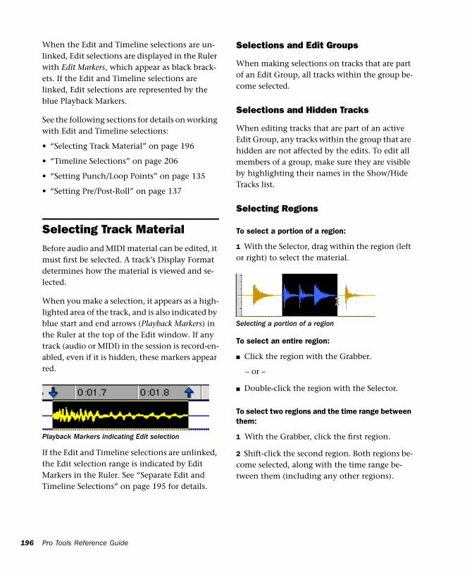
196
When the Edit and Timeline selections are un-linked, Edit selections are displayed in the Ruler with Edit Markers, which appear as black brack-ets. If the Edit and Timeline selections are linked, Edit selections are represented by the blue Playback Markers.
See the following sections for details on working with Edit and Timeline selections:
• “Selecting Track Material” on page 196
• “Timeline Selections” on page 206
• “Setting Punch/Loop Points” on page 135
• “Setting Pre/Post-Roll” on page 137
Selecting Track MaterialBefore audio and MIDI material can be edited, it must first be selected. A track’s Display Format determines how the material is viewed and se-lected.
When you make a selection, it appears as a high-lighted area of the track, and is also indicated by blue start and end arrows (Playback Markers) in the Ruler at the top of the Edit window. If any track (audio or MIDI) in the session is record-en-abled, even if it is hidden, these markers appear red.
If the Edit and Timeline selections are unlinked, the Edit selection range is indicated by Edit Markers in the Ruler. See “Separate Edit and Timeline Selections” on page 195 for details.
Playback Markers indicating Edit selection
Pro Tools Reference Guide
Selections and Edit Groups
When making selections on tracks that are part of an Edit Group, all tracks within the group be-come selected.
Selections and Hidden Tracks
When editing tracks that are part of an active Edit Group, any tracks within the group that are hidden are not affected by the edits. To edit all members of a group, make sure they are visible by highlighting their names in the Show/Hide Tracks list.
Selecting Regions
To select a portion of a region:
1 With the Selector, drag within the region (left or right) to select the material.
To select an entire region:
■ Click the region with the Grabber.
– or –
■ Double-click the region with the Selector.
To select two regions and the time range between them:
1 With the Grabber, click the first region.
2 Shift-click the second region. Both regions be-come selected, along with the time range be-tween them (including any other regions).
Selecting a portion of a region
To select an entire track:
■ Click in the track with the Selector and then choose Edit > Select All.
– or –
■ Triple-click in the track with the Selector.
To select all regions in all tracks:
1 Select the “All” Edit Group in the Groups List.
2 Click in any track with the Selector and choose Edit > Select All.
– or –
Triple-click with the Selector in any track.
Selecting All from Timebase Rulers
You can select all regions in all tracks displayed in the Edit window by double-clicking in any Timebase Ruler.
To select all material in all displayed audio and MIDI tracks:
1 Make sure the Edit and Timeline selections are linked.
2 Double-click in any Timebase Ruler. All re-gions in all displayed audio and MIDI tracks are selected. Tracks that are hidden are not selected.
To select all material in all tracks, along with Conductor events:
1 Make sure the Edit and Timeline selections are linked.
2 While pressing Option (Macintosh) or Con-trol (Windows), double-click in any Timebase Ruler. All regions in all displayed audio and MIDI tracks are selected, along with all events in each of the Conductor tracks.
Making Selections While Playing
Pro Tools lets you make on-the-fly selections with the Arrow keys.
To make a selection while playing:
1 Make sure to select Operations > Link Edit and Timeline selection.
2 With the Selector, click somewhere near the beginning of the track in which you want to make the selection.
3 Click Play in the Transport window to begin playback.
4 When playback reaches the point where you want the selection to begin, press the Down Ar-row key.
5 Press the Up Arrow key at the point where you want the selection to end. The selected range be-comes highlighted.
6 To stop playback, click Stop in the Transport window.
To automatically scroll to the beginning of the selection (or to the location of the on-screen cursor), press the Left Arrow key. To scroll to the end of the selection, press the Right Arrow key.
Object Selections (TDM Systems Only)
You can use the Object Grabber to select discon-tiguous regions on one or more tracks. Discon-tiguous selections must encompass entire re-gions. If you want a discontiguous selection to include a portion of a region, first turn the por-tion into a new region with the Separation Grabber (see “Separation Grabber” on page 211) or the Separate Region command (see “Separate Region Command” on page 210).
NOTE: The Object Grabber is not available when the Edit mode is set to Shuffle or Spot.
Chapter 16: Playing and Selecting Track Material 197
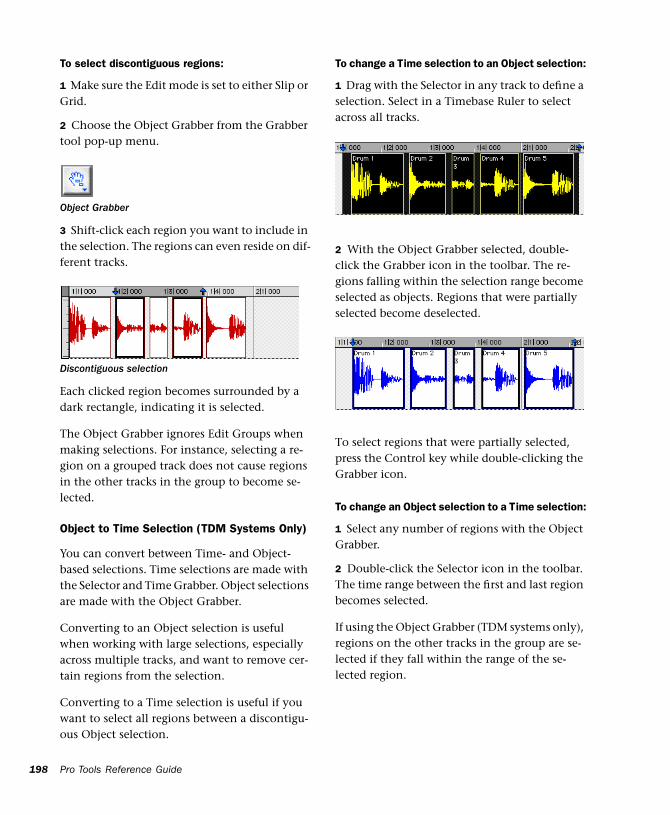
198
To select discontiguous regions:
1 Make sure the Edit mode is set to either Slip or Grid.
2 Choose the Object Grabber from the Grabber tool pop-up menu.
3 Shift-click each region you want to include in the selection. The regions can even reside on dif-ferent tracks.
Each clicked region becomes surrounded by a dark rectangle, indicating it is selected.
The Object Grabber ignores Edit Groups when making selections. For instance, selecting a re-gion on a grouped track does not cause regions in the other tracks in the group to become se-lected.
Object to Time Selection (TDM Systems Only)
You can convert between Time- and Object-based selections. Time selections are made with the Selector and Time Grabber. Object selections are made with the Object Grabber.
Converting to an Object selection is useful when working with large selections, especially across multiple tracks, and want to remove cer-tain regions from the selection.
Converting to a Time selection is useful if you want to select all regions between a discontigu-ous Object selection.
Object Grabber
Discontiguous selection
Pro Tools Reference Guide
To change a Time selection to an Object selection:
1 Drag with the Selector in any track to define a selection. Select in a Timebase Ruler to select across all tracks.
2 With the Object Grabber selected, double-click the Grabber icon in the toolbar. The re-gions falling within the selection range become selected as objects. Regions that were partially selected become deselected.
To select regions that were partially selected, press the Control key while double-clicking the Grabber icon.
To change an Object selection to a Time selection:
1 Select any number of regions with the Object Grabber.
2 Double-click the Selector icon in the toolbar. The time range between the first and last region becomes selected.
If using the Object Grabber (TDM systems only), regions on the other tracks in the group are se-lected if they fall within the range of the se-lected region.
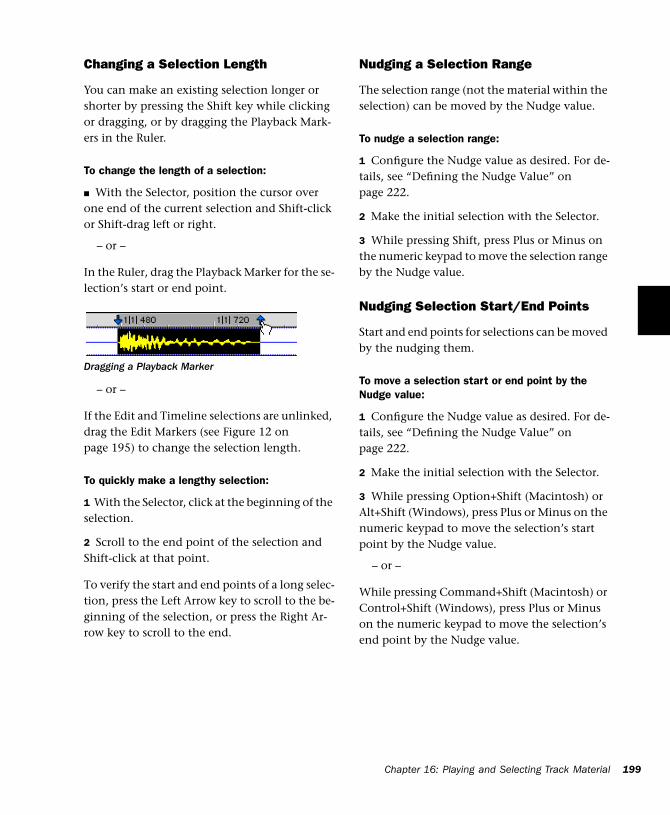
Changing a Selection Length
You can make an existing selection longer or shorter by pressing the Shift key while clicking or dragging, or by dragging the Playback Mark-ers in the Ruler.
To change the length of a selection:
■ With the Selector, position the cursor over one end of the current selection and Shift-click or Shift-drag left or right.
– or –
In the Ruler, drag the Playback Marker for the se-lection’s start or end point.
– or –
If the Edit and Timeline selections are unlinked, drag the Edit Markers (see Figure 12 on page 195) to change the selection length.
To quickly make a lengthy selection:
1 With the Selector, click at the beginning of the selection.
2 Scroll to the end point of the selection and Shift-click at that point.
To verify the start and end points of a long selec-tion, press the Left Arrow key to scroll to the be-ginning of the selection, or press the Right Ar-row key to scroll to the end.
Dragging a Playback Marker
Nudging a Selection Range
The selection range (not the material within the selection) can be moved by the Nudge value.
To nudge a selection range:
1 Configure the Nudge value as desired. For de-tails, see “Defining the Nudge Value” on page 222.
2 Make the initial selection with the Selector.
3 While pressing Shift, press Plus or Minus on the numeric keypad to move the selection range by the Nudge value.
Nudging Selection Start/End Points
Start and end points for selections can be moved by the nudging them.
To move a selection start or end point by the Nudge value:
1 Configure the Nudge value as desired. For de-tails, see “Defining the Nudge Value” on page 222.
2 Make the initial selection with the Selector.
3 While pressing Option+Shift (Macintosh) or Alt+Shift (Windows), press Plus or Minus on the numeric keypad to move the selection’s start point by the Nudge value.
– or –
While pressing Command+Shift (Macintosh) or Control+Shift (Windows), press Plus or Minus on the numeric keypad to move the selection’s end point by the Nudge value.
Chapter 16: Playing and Selecting Track Material 199
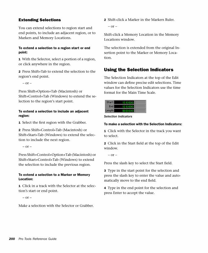
200
Extending Selections
You can extend selections to region start and end points, to include an adjacent region, or to Markers and Memory Locations.
To extend a selection to a region start or end point:
1 With the Selector, select a portion of a region, or click anywhere in the region.
2 Press Shift+Tab to extend the selection to the region’s end point.
– or –
Press Shift+Option+Tab (Macintosh) or Shift+Control+Tab (Windows) to extend the se-lection to the region’s start point.
To extend a selection to include an adjacent region:
1 Select the first region with the Grabber.
2 Press Shift+Control+Tab (Macintosh) or Shift+Start+Tab (Windows) to extend the selec-tion to include the next region.
– or –
Press Shift+Control+Option+Tab (Macintosh) or Shift+Start+Control+Tab (Windows) to extend the selection to include the previous region.
To extend a selection to a Marker or Memory Location:
1 Click in a track with the Selector at the selec-tion’s start or end point.
– or –
Make a selection with the Selector or Grabber.
Pro Tools Reference Guide
2 Shift-click a Marker in the Markers Ruler.
– or –
Shift-click a Memory Location in the Memory Locations window.
The selection is extended from the original In-sertion point to the Marker or Memory Loca-tion.
Using the Selection Indicators
The Selection Indicators at the top of the Edit window can define precise edit selections. Time values for the Selection Indicators use the time format for the Main Time Scale.
To make a selection with the Selection Indicators:
1 Click with the Selector in the track you want to select.
2 Click in the Start field at the top of the Edit window.
– or –
Press the slash key to select the Start field.
3 Type in the start point for the selection and press the slash key to enter the value and auto-matically move to the end field.
4 Type in the end point for the selection and press Enter to accept the value.
Selection Indicators
Numeric Entry Shortcuts for Selection Indicators
You can use the following shortcuts for entering values in the Selection Indicators:
■ Press the slash key to cycle through the three Selection Indicators.
■ Use period (.) or the Left/Right Arrow keys to move through the different time fields in each Selection Indicator.
■ Press the Up/Down Arrow keys to increase or decrease the numerical values.
■ Command-drag (Macintosh) or Control-drag (Windows) a selected field to scroll to a new value.
■ Press Plus (+) or Minus (–) along with an ac-companying number to add or subtract from the current field value.
For example, to add 10 to a current field value, cycle to the field, press the Plus key, type “10” and then press Enter.
NOTE: If using Calculator Entry mode with the Time Scale set to Bars:Beats, see “Calculator Entry Mode and Bars:Beats” on page 201.
■ Press Escape to exit the Selection Indicators without entering any values.
Calculator Entry Mode and Bars:Beats
To use Minus in Calculator mode with the Time Scale set to Bars:Beats:
1 Highlight the time field you want to change.
2 While pressing Command (Macintosh) or Control (Windows), press Minus on the nu-meric keypad.
These shortcuts can also be used to enter start and end values in the Transport win-dow.
3 Type the amount you want to subtract from the current time value, then press Enter.
Selecting Across Multiple Tracks
To perform edits across multiple tracks or all tracks, you must first select the tracks. Do this by making selections on tracks that are grouped (see “Grouping Tracks” on page 85), by extend-ing selections to other tracks, or by selecting in a Timebase Ruler (for all tracks).
To extend a selection to another track:
1 Using the Selector or Grabber, make a selec-tion in the first track.
2 Shift-click in additional tracks with the Selec-tor. An identical range is selected for each addi-tional track.
To shorten or lengthen the selection across each of the tracks, press Shift while dragging to change the range of the selection.
To select across all tracks, do one of the following:
■ With the Selector, Option-Shift-drag (Macin-tosh) or Alt-Shift-drag (Windows) in any track.
■ Enable the All Edit Group and make a selec-tion in any track.
■ Drag with the Selector in any Timebase Ruler (make sure the Edit and Timeline Selections are linked).
These selections include all tracks in the Edit window, but do not include the Conductor tracks (for Tempo, Meter, and Markers).
To select across all tracks, including the Conductor tracks:
■ Option-drag (Macintosh) or Alt-drag (Win-dows) with the Selector in any Timebase Ruler.
Chapter 16: Playing and Selecting Track Material 201
202
Moving and Extending Selections between Tracks (TDM Systems Only)
With the Commands Focus enabled (TDM sys-tems only), Edit selections can be moved or ex-tended to adjacent tracks.
To move a selection to an adjacent track:
1 Enable the Commands Focus by clicking its button in the upper left of the Edit window.
2 With the Selector or Grabber, make a track se-lection.
3 Press P on your computer keyboard to move the selection to the previous track.
– or –
Press semicolon to move the selection to the next track.
In either instance, the original Edit selection be-comes deselected.
To extend a selection to an adjacent track:
1 Enable the Commands Focus.
2 With the Selector or Grabber, make a track se-lection.
3 Press Shift+P to extend the selection to the previous track.
– or –
4 Press Shift+semicolon to extend the selection to the next track.
In either instance, the original Edit selection re-mains selected.
Commands Key button, enabled
Pro Tools Reference Guide
To remove the top or bottom track from a selection:
■ Press Control+Option+P (Macintosh) or Start+Alt+P (Windows) to remove the top track.
– or –
■ Press Control+Option+semicolon (Macin-tosh) or Start+Alt+semicolon (Windows) to re-move the bottom track.
Other Useful Selection Techniques
Following are some additional selection tech-niques.
To position the edit cursor precisely at a region start, end, or sync point:
1 Click with the Selector in the track.
2 Press Tab to move the cursor to the next re-gion start, end, or sync point.
– or –
3 Press Option+Tab (Macintosh) or Control+Tab (Windows) to move the cursor to the previous region start, end, or sync point.
To make a selection with the Scrubber:
1 Choose Setups > Preferences. In the Operation page of the Preferences dialog, select the option for “Edit Insertion Follows Scrub/Shuttle,” then click Done.
2 Scrub with the Scrubber to find an appropriate start point for the selection, then release.
3 While pressing Shift, scrub to an appropriate end point for the selection, then release. The range between the initial and final scrub be-comes selected.
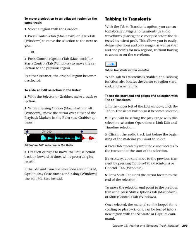
To move a selection to an adjacent region on the same track:
1 Select a region with the Grabber.
2 Press Control+Tab (Macintosh) or Start+Tab (Windows) to move the selection to the next re-gion.
– or –
3 Press Control+Option+Tab (Macintosh) or Start+Control+Tab (Windows) to move the se-lection to the previous region.
In either instance, the original region becomes deselected.
To slide an Edit selection in the Ruler:
1 With the Selector or Grabber, make a track se-lection.
2 While pressing Option (Macintosh) or Alt (Windows), move the cursor over either of the Playback Markers in the Ruler (the Grabber ap-pears).
3 Drag left or right to move the Edit selection back or forward in time, while preserving its length.
If the Edit and Timeline selections are unlinked, Option-drag (Macintosh) or Alt-drag (Windows) the Edit Markers instead.
Sliding an Edit selection in the Ruler
Tabbing to Transients
With the Tab to Transients option, you can au-tomatically navigate to transients in audio waveforms, placing the cursor just before the de-tected transient peak. This allows you to easily define selections and play ranges, as well as start and end points for new regions, without having to zoom in on the waveform.
When Tab to Transients is enabled, the Tabbing function also locates the cursor to region start, end, and sync points.
To set the start and end points of a selection with Tab to Transients:
1 In the upper left of the Edit window, click the Tab to Transients button so it becomes selected.
2 If you will be setting the play range with this selection, selection Operations > Link Edit and Timeline Selection.
3 Click in the audio track just before the begin-ning of the material you want to select.
4 Press Tab repeatedly until the cursor locates to the transient at the start of the selection.
If necessary, you can move to the previous tran-sient by pressing Option+Tab (Macintosh) or Control+Tab (Windows).
5 Press Shift+Tab until the cursor locates to the end of the selection.
To move the selection end point to the previous transient, press Shift+Option+Tab (Macintosh) or Shift+Control+Tab (Windows).
Once selected, the material can be looped for re-cording or playback, or it can be turned into a new region with the Separate or Capture com-mand.
Tab to Transients button, enabled
Chapter 16: Playing and Selecting Track Material 203
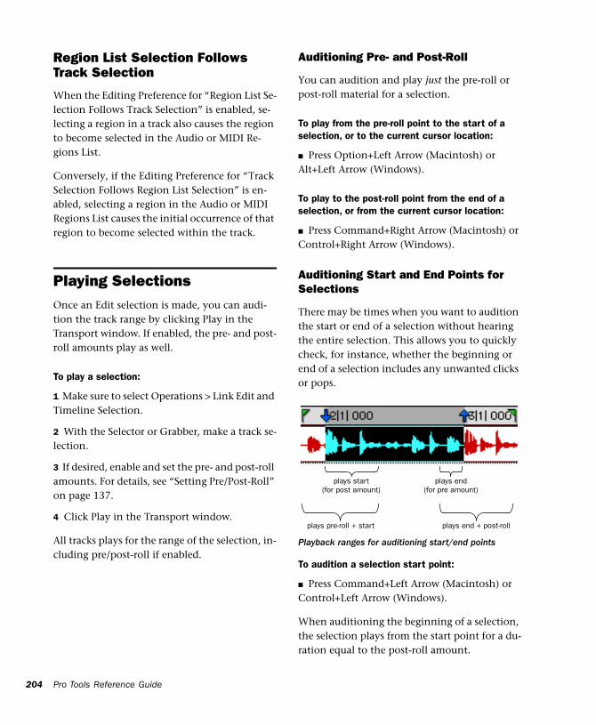
204
Region List Selection Follows Track Selection
When the Editing Preference for “Region List Se-lection Follows Track Selection” is enabled, se-lecting a region in a track also causes the region to become selected in the Audio or MIDI Re-gions List.
Conversely, if the Editing Preference for “Track Selection Follows Region List Selection” is en-abled, selecting a region in the Audio or MIDI Regions List causes the initial occurrence of that region to become selected within the track.
Playing SelectionsOnce an Edit selection is made, you can audi-tion the track range by clicking Play in the Transport window. If enabled, the pre- and post-roll amounts play as well.
To play a selection:
1 Make sure to select Operations > Link Edit and Timeline Selection.
2 With the Selector or Grabber, make a track se-lection.
3 If desired, enable and set the pre- and post-roll amounts. For details, see “Setting Pre/Post-Roll” on page 137.
4 Click Play in the Transport window.
All tracks plays for the range of the selection, in-cluding pre/post-roll if enabled.
Pro Tools Reference Guide
Auditioning Pre- and Post-Roll
You can audition and play just the pre-roll or post-roll material for a selection.
To play from the pre-roll point to the start of a selection, or to the current cursor location:
■ Press Option+Left Arrow (Macintosh) or Alt+Left Arrow (Windows).
To play to the post-roll point from the end of a selection, or from the current cursor location:
■ Press Command+Right Arrow (Macintosh) or Control+Right Arrow (Windows).
Auditioning Start and End Points for Selections
There may be times when you want to audition the start or end of a selection without hearing the entire selection. This allows you to quickly check, for instance, whether the beginning or end of a selection includes any unwanted clicks or pops.
To audition a selection start point:
■ Press Command+Left Arrow (Macintosh) or Control+Left Arrow (Windows).
When auditioning the beginning of a selection, the selection plays from the start point for a du-ration equal to the post-roll amount.
Playback ranges for auditioning start/end points
plays start(for post amount)
plays pre-roll + start
plays end(for pre amount)
plays end + post-roll
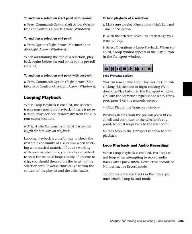
To audition a selection start point with pre-roll:
■ Press Command+Option+Left Arrow (Macin-tosh) or Control+Alt+Left Arrow (Windows).
To audition a selection end point:
■ Press Option+Right Arrow (Macintosh) or Alt+Right Arrow (Windows).
When auditioning the end of a selection, play-back begins before the end point by the pre-roll amount.
To audition a selection end point with post-roll:
■ Press Command+Option+Right Arrow (Mac-intosh) or Control+Alt+Right Arrow (Windows).
Looping Playback
When Loop Playback is enabled, the selected track range repeats on playback. If there is no se-lection, playback occurs normally from the cur-rent cursor location.
NOTE: A selection must be at least 1 second in length for it to loop on playback.
Looping playback is a useful way to check the rhythmic continuity of a selection when work-ing with musical material. If you’re working with one-bar selections, you can loop playback to see if the material loops cleanly. If it seems to skip, you should then adjust the length of the selection until it works “musically” within the context of the playlist and the other tracks.
To loop playback of a selection:
1 Make sure to select Operations > Link Edit and Timeline Selection.
2 With the Selector, select the track range you want to loop.
3 Select Operations > Loop Playback. When en-abled, a loop symbol appears in the Play button in the Transport window.
You can also enable Loop Playback by Control-clicking (Macintosh) or Right-clicking (Win-dows) the Play button in the Transport window. Or, with the Numeric Keypad Mode set to Trans-port, press 4 on the numeric keypad.
4 Click Play in the Transport window.
Playback begins from the pre-roll point (if en-abled) and continues to the selection’s end point, where it loops back to the start point.
5 Click Stop in the Transport window to stop playback.
Loop Playback and Audio Recording
When Loop Playback is enabled, Pro Tools will not loop when attempting to record audio tracks with QuickPunch, Destructive Record, or Nondestructive Record mode.
To loop record audio tracks in Pro Tools, you must enable Loop Record mode.
Loop Playback enabled
Chapter 16: Playing and Selecting Track Material 205
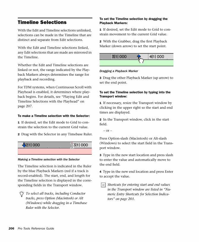
206
Timeline SelectionsWith the Edit and Timeline selections unlinked, selections can be made in the Timeline that are distinct and separate from Edit selections.
With the Edit and Timeline selections linked, any Edit selections that are made are mirrored in the Timeline.
Whether the Edit and Timeline selections are linked or not, the range indicated by the Play-back Markers always determines the range for playback and recording.
For TDM systems, when Continuous Scroll with Playhead is enabled, it determines where play-back begins. For details, see “Playing Edit and Timeline Selections with the Playhead” on page 207.
To make a Timeline selection with the Selector:
1 If desired, set the Edit mode to Grid to con-strain the selection to the current Grid value.
2 Drag with the Selector in any Timebase Ruler.
The Timeline selection is indicated in the Ruler by the blue Playback Markers (red if a track is record-enabled). The start, end, and length for the Timeline selection is displayed in the corre-sponding fields in the Transport window.
Making a Timeline selection with the Selector
To select all tracks, including Conductor tracks, press Option (Macintosh) or Alt (Windows) while dragging in a Timebase Ruler with the Selector.
Pro Tools Reference Guide
To set the Timeline selection by dragging the Playback Markers:
1 If desired, set the Edit mode to Grid to con-strain movement to the current Grid value.
2 With the Grabber, drag the first Playback Marker (down arrow) to set the start point.
3 Drag the other Playback Marker (up arrow) to set the end point.
To set the Timeline selection by typing into the Transport window:
1 If necessary, resize the Transport window by clicking in the upper right so the start and end times are displayed.
2 In the Transport window, click in the start field.
– or –
Press Option-slash (Macintosh) or Alt-slash (Windows) to select the start field in the Trans-port window.
3 Type in the new start location and press slash to enter the value and automatically move to the end field.
4 Type in the new end location and press Enter to accept the value.
Dragging a Playback Marker
Shortcuts for entering start and end values in the Transport window are listed in “Nu-meric Entry Shortcuts for Selection Indica-tors” on page 201.
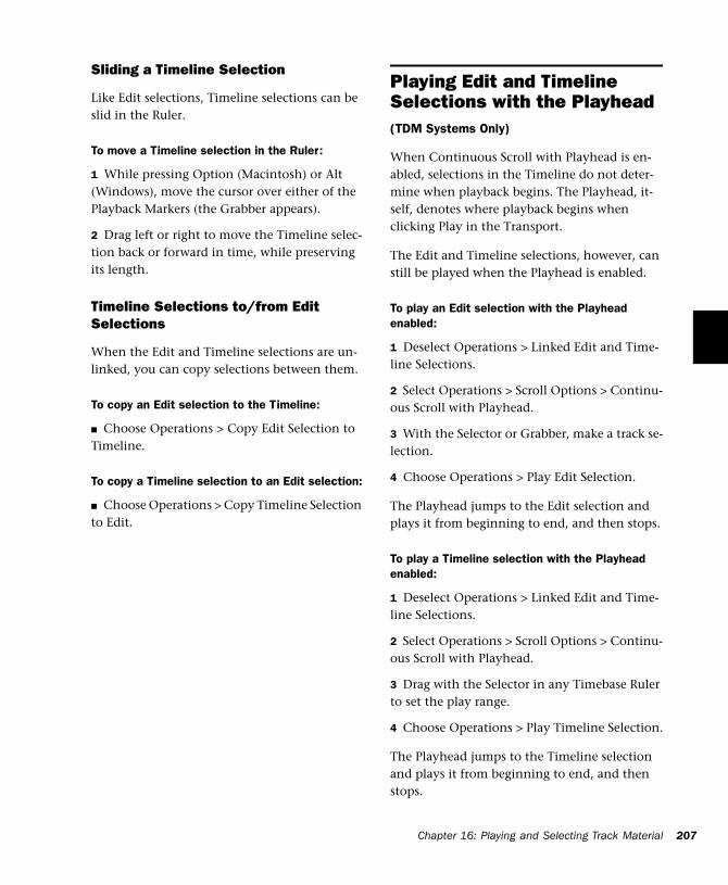
Sliding a Timeline Selection
Like Edit selections, Timeline selections can be slid in the Ruler.
To move a Timeline selection in the Ruler:
1 While pressing Option (Macintosh) or Alt (Windows), move the cursor over either of the Playback Markers (the Grabber appears).
2 Drag left or right to move the Timeline selec-tion back or forward in time, while preserving its length.
Timeline Selections to/from Edit Selections
When the Edit and Timeline selections are un-linked, you can copy selections between them.
To copy an Edit selection to the Timeline:
■ Choose Operations > Copy Edit Selection to Timeline.
To copy a Timeline selection to an Edit selection:
■ Choose Operations > Copy Timeline Selection to Edit.
Playing Edit and Timeline Selections with the Playhead(TDM Systems Only)
When Continuous Scroll with Playhead is en-abled, selections in the Timeline do not deter-mine when playback begins. The Playhead, it-self, denotes where playback begins when clicking Play in the Transport.
The Edit and Timeline selections, however, can still be played when the Playhead is enabled.
To play an Edit selection with the Playhead enabled:
1 Deselect Operations > Linked Edit and Time-line Selections.
2 Select Operations > Scroll Options > Continu-ous Scroll with Playhead.
3 With the Selector or Grabber, make a track se-lection.
4 Choose Operations > Play Edit Selection.
The Playhead jumps to the Edit selection and plays it from beginning to end, and then stops.
To play a Timeline selection with the Playhead enabled:
1 Deselect Operations > Linked Edit and Time-line Selections.
2 Select Operations > Scroll Options > Continu-ous Scroll with Playhead.
3 Drag with the Selector in any Timebase Ruler to set the play range.
4 Choose Operations > Play Timeline Selection.
The Playhead jumps to the Timeline selection and plays it from beginning to end, and then stops.
Chapter 16: Playing and Selecting Track Material 207
208
Moving the Playhead
When Continuous Scroll with Playhead is en-abled, the Playhead can be moved forward or back to the next region boundary in the selected track.
To move the Playhead through a track’s region boundaries:
1 Click in the track with the Selector.
2 Press Tab to move the Playhead forward to the next region boundary.
– or –
3 Press Option+Tab (Macintosh) or Control+Tab (Windows) to move the Playhead back to the previous region boundary.
Pro Tools Reference Guide
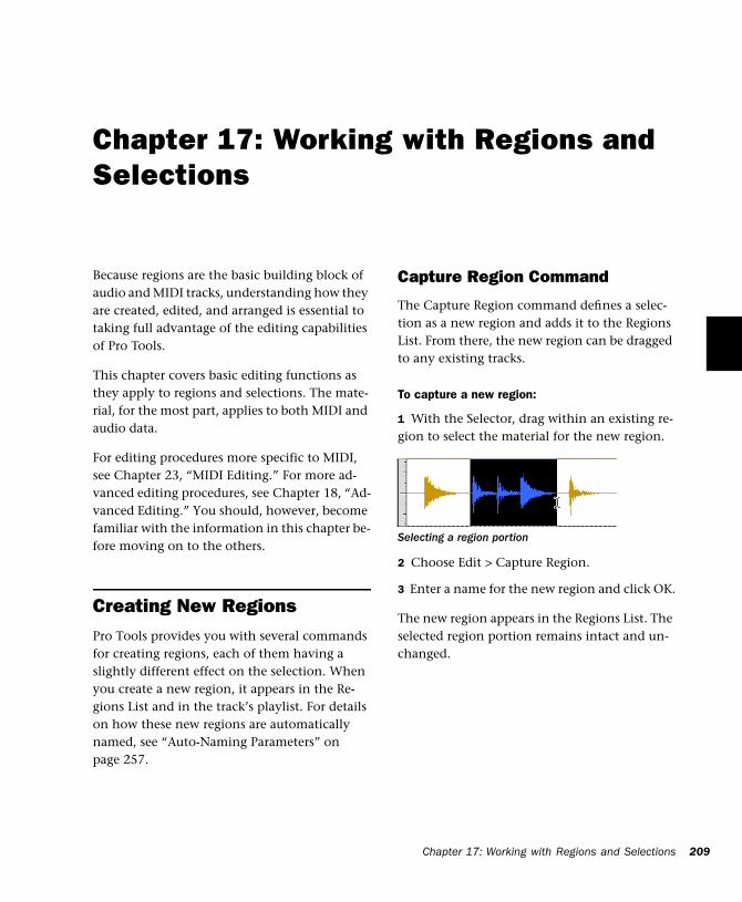
Chapter 17: Working with Regions and Selections
Because regions are the basic building block of audio and MIDI tracks, understanding how they are created, edited, and arranged is essential to taking full advantage of the editing capabilities of Pro Tools.
This chapter covers basic editing functions as they apply to regions and selections. The mate-rial, for the most part, applies to both MIDI and audio data.
For editing procedures more specific to MIDI, see Chapter 23, “MIDI Editing.” For more ad-vanced editing procedures, see Chapter 18, “Ad-vanced Editing.” You should, however, become familiar with the information in this chapter be-fore moving on to the others.
Creating New RegionsPro Tools provides you with several commands for creating regions, each of them having a slightly different effect on the selection. When you create a new region, it appears in the Re-gions List and in the track’s playlist. For details on how these new regions are automatically named, see “Auto-Naming Parameters” on page 257.
Capture Region Command
The Capture Region command defines a selec-tion as a new region and adds it to the Regions List. From there, the new region can be dragged to any existing tracks.
To capture a new region:
1 With the Selector, drag within an existing re-gion to select the material for the new region.
2 Choose Edit > Capture Region.
3 Enter a name for the new region and click OK.
The new region appears in the Regions List. The selected region portion remains intact and un-changed.
Selecting a region portion
Chapter 17: Working with Regions and Selections 209
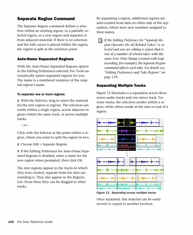
210
Separate Region Command
The Separate Region command defines a selec-tion within an existing region, or a partially se-lected region, as a new region and separates it from adjacent material. If there is no selection and the Edit cursor is placed within the region, the region is split at the insertion point.
Auto-Name Separated Regions
With the Auto-Name Separated Regions option in the Editing Preferences selected, Pro Tools au-tomatically names separated regions for you. The name is a numbered variation of the origi-nal region’s name.
To separate one or more regions:
1 With the Selector, drag to select the material for the new region or regions. The selection can reside within a single region, across adjacent re-gions within the same track, or across multiple tracks.
– or –
Click with the Selector at the point within a re-gion, where you want to split the region in two.
2 Choose Edit > Separate Region.
3 If the Editing Preference for Auto-Name Sepa-rated Regions is disabled, enter a name for the new region when prompted, then click OK.
The new regions appear in the tracks in which they were created, separate from the data sur-rounding it. They also appear in the Regions List. From there they can be dragged to other tracks.
Pro Tools Reference Guide
By separating a region, additional regions are auto-created from data on either side of the sep-aration, which have new numbers assigned to their names.
Separating Multiple Tracks
Figure 13 illustrates a a separation across three mono audio tracks and one stereo track. For some tracks, the selection resides within a re-gion, while others reside at the start or end of a region.
Once separated, this material can be easily moved or copied to another location.
If the Editing Preference for “Separate Re-gion Operates On All Related Takes” is se-lected and you are editing a region that is one of a number of related takes with the same User Time Stamp (created with loop recording, for example), the Separate Region command affects each take. For details see, “Editing Preferences and Take Regions” on page 135.
Figure 13. Separating across multiple tracks
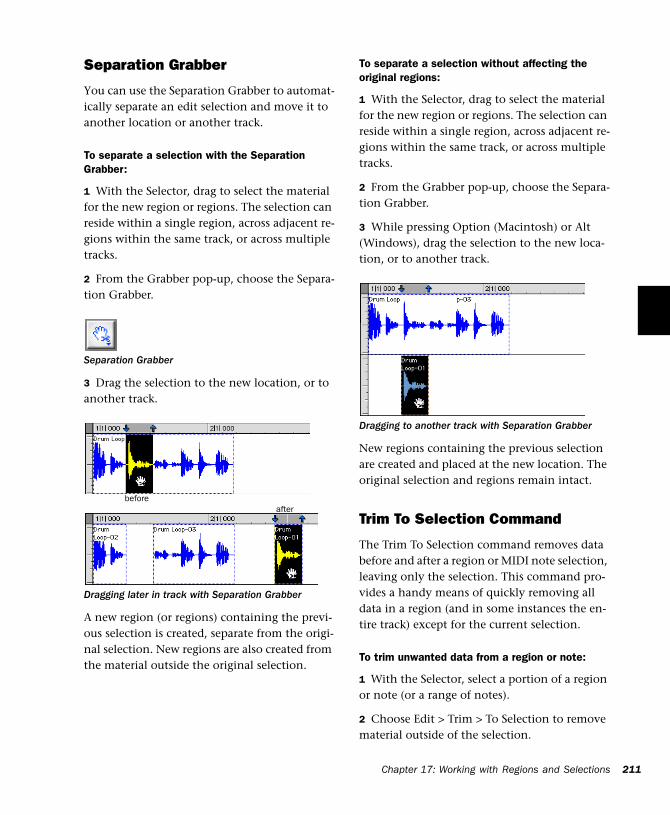
Separation Grabber
You can use the Separation Grabber to automat-ically separate an edit selection and move it to another location or another track.
To separate a selection with the Separation Grabber:
1 With the Selector, drag to select the material for the new region or regions. The selection can reside within a single region, across adjacent re-gions within the same track, or across multiple tracks.
2 From the Grabber pop-up, choose the Separa-tion Grabber.
3 Drag the selection to the new location, or to another track.
A new region (or regions) containing the previ-ous selection is created, separate from the origi-nal selection. New regions are also created from the material outside the original selection.
Separation Grabber
Dragging later in track with Separation Grabber
beforeafter
To separate a selection without affecting the original regions:
1 With the Selector, drag to select the material for the new region or regions. The selection can reside within a single region, across adjacent re-gions within the same track, or across multiple tracks.
2 From the Grabber pop-up, choose the Separa-tion Grabber.
3 While pressing Option (Macintosh) or Alt (Windows), drag the selection to the new loca-tion, or to another track.
New regions containing the previous selection are created and placed at the new location. The original selection and regions remain intact.
Trim To Selection Command
The Trim To Selection command removes data before and after a region or MIDI note selection, leaving only the selection. This command pro-vides a handy means of quickly removing all data in a region (and in some instances the en-tire track) except for the current selection.
To trim unwanted data from a region or note:
1 With the Selector, select a portion of a region or note (or a range of notes).
2 Choose Edit > Trim > To Selection to remove material outside of the selection.
Dragging to another track with Separation Grabber
Chapter 17: Working with Regions and Selections 211
212
Healing a SeparationThe Heal Separation command returns sepa-rated regions to their original state—provided the regions are still next to each other and their relative start/end points haven’t changed since the separation.
If you have trimmed or otherwise changed the start or end points of the two regions, or moved them further away from each other, you won’t be able to repair them with the Heal Separation command. It is not possible to heal two regions created from different audio files.
To heal a separation between two regions:
1 With the Selector, make a selection that in-cludes part of the first region, the entire separa-tion between the regions, and part of the second region.
2 Choose Edit > Heal Separation.
If the regions won’t heal, there are other ways to return the separated regions to a single region.
◆ Delete one of the two separated regions (make sure you’re in Slip mode so the gap doesn’t close) and use the Trimmer to expand the re-maining region to its original length. For infor-mation on using the Trimmer, see “The Trimmer Tool” on page 215.
– or –
◆ Delete both of the separated regions and drag the original region from the Regions List to the original location. For information on placing re-gions, see “Placing Regions in Tracks” on page 212.
Pro Tools Reference Guide
Placing Regions in TracksOnce you have created a region, it appears in the Audio or MIDI Regions List. From there you can drag it to a track to add to an existing arrange-ment of regions, or you can create a new track and start adding regions from scratch. The exact placement of regions in a track depends on whether the Edit mode is set to Shuffle, Slip, Spot, or Grid (see “Edit Modes” on page 179 for details).
For information on locating regions in the Re-gions List by typing the first few letters of their name, see “Keyboard Selection of Regions” on page 178.
To place a region in a track:
1 In the Audio or MIDI Regions list, select the region or regions you want to place in a track.
2 Drag the selected regions from the Regions List to a track at the desired point.
If dragging multiple regions, the regions are placed on adjacent tracks. If dragging a stereo re-gion, it must be placed in a stereo track or in two mono tracks.
Regions are placed according to the current Edit mode:
• In Shuffle mode, existing track regions are slid as necessary to make room for the new region.
• In Spot mode, you are prompted by the Spot dialog to enter a location for the dragged re-gion (see “Spotting Regions” on page 219).
• In Grid mode, the dragged region snaps to the nearest Grid boundary.
• In Slip mode, the regions are placed freely anywhere in the destination track.
Placing Regions at the Edit Insertion Point
You can easily place and align a region’s start, end, or sync point to the Edit insertion point. This technique is useful in post production ap-plications since it allows you to set a reference point and quickly place sound effects while en-suring that their start point remains consistent.
You can drag a region from the same track, from another track, or from the Audio or MIDI Re-gions List.
NOTE: For TDM systems, when Continuous Scroll with Playhead is selected, regions snap to the play-head, instead of the Edit insertion point.
To place the start of a region at the Edit insertion point:
1 Click with the Selector in the track at the de-sired time location.
2 While pressing Control (Macintosh) or the Start key (Windows), drag the region from the Regions list, or from another track, to the desti-nation track.
– or –
If the region is already in the track, Control-click (Macintosh) or Start-click (Windows) the region with the Grabber.
Use the Replace Region function to replace all occurrences of a region (in all tracks) with a different region from the Regions List. See “Replacing Regions” on page 235.
To place the end of a region at the Edit insertion point:
1 Click with the Selector in the track at the de-sired time location.
2 While pressing Command+Control (Macin-tosh) or Control+Start key (Windows), drag the region from the Regions list, or from another track, to the destination track.
– or –
If the region is already in the track, Command-Control-click (Macintosh) or Control-Start-click (Windows) the region with the Grabber.
To place the sync point of a region at the Edit insertion point:
1 Click with the Selector in the track at the de-sired time location.
2 While pressing Shift+Control (Macintosh) or Shift+Start key (Windows), drag the region from the Regions list, or from another track, to the destination track.
– or –
If the region is already in the track, Shift-Con-trol-click (Macintosh) or Shift-Start-click (Win-dows) the region with the Grabber.
Chapter 17: Working with Regions and Selections 213
214
Aligning to Region Start Points
The start, end, and sync point of one region can be aligned to the start of a different region on another track.
NOTE: For TDM systems, if Continuous Scroll with Playhead is enabled, region start, end, and sync points align to the playhead.
To align the start points of regions on different tracks:
1 With the Grabber, select the region you want to align to by clicking it.
2 For TDM systems, if Continuous Scroll with Playhead is enabled, move the playhead to the start of the selected region. For details, see “Moving the Playhead” on page 208.
3 With the Grabber, Control-click (Macintosh) or Start-click (Windows) the region you want to move.
– or –
Control-drag (Macintosh) or Start-drag (Win-dows) a region from the Regions List to another track.
The start point of the second region is aligned to the start of the first region.
To align the end point of a region to the start of another region (on a different track):
1 With the Grabber, select the region you want to align to by clicking it.
2 For TDM systems, if Continuous Scroll with Playhead is enabled, move the playhead to the start of the selected region. For details, see “Moving the Playhead” on page 208.
Pro Tools Reference Guide
3 With the Grabber, Command-Control-click (Macintosh) or Control-Start-click (Windows) the region you want to move.
– or –
Command-Control-drag (Macintosh) or Con-trol-Start-drag (Windows) a region from the Re-gions List to another track.
The end point of the second region is aligned to the start of the first region.
To align the sync point of a region to the start of another region (on a different track):
1 With the Grabber, select the region you want to align to by clicking it.
2 For TDM systems, if Continuous Scroll with Playhead is enabled, move the playhead to the start of the selected region. For details, see “Moving the Playhead” on page 208.
3 With the Grabber, Shift-Control-click (Macin-tosh) or Shift-Start-click (Windows) the region you want to move.
– or –
Shift-Control-drag (Macintosh) or Shift-Start-drag (Windows) a region from the Regions List to another track.
The sync point of the second region is aligned to the start of the first region.
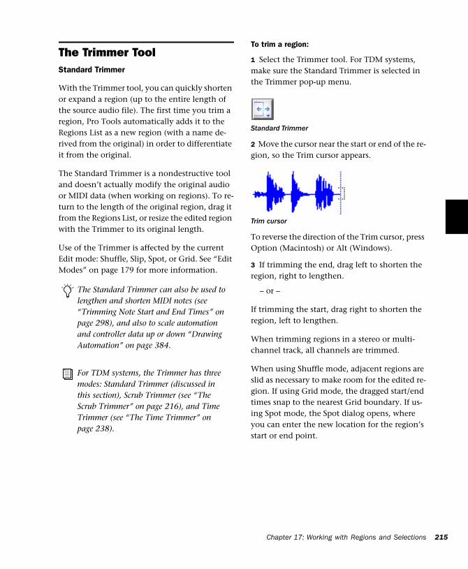
The Trimmer ToolStandard Trimmer
With the Trimmer tool, you can quickly shorten or expand a region (up to the entire length of the source audio file). The first time you trim a region, Pro Tools automatically adds it to the Regions List as a new region (with a name de-rived from the original) in order to differentiate it from the original.
The Standard Trimmer is a nondestructive tool and doesn’t actually modify the original audio or MIDI data (when working on regions). To re-turn to the length of the original region, drag it from the Regions List, or resize the edited region with the Trimmer to its original length.
Use of the Trimmer is affected by the current Edit mode: Shuffle, Slip, Spot, or Grid. See “Edit Modes” on page 179 for more information.
The Standard Trimmer can also be used to lengthen and shorten MIDI notes (see “Trimming Note Start and End Times” on page 298), and also to scale automation and controller data up or down “Drawing Automation” on page 384.
For TDM systems, the Trimmer has three modes: Standard Trimmer (discussed in this section), Scrub Trimmer (see “The Scrub Trimmer” on page 216), and Time Trimmer (see “The Time Trimmer” on page 238).
To trim a region:
1 Select the Trimmer tool. For TDM systems, make sure the Standard Trimmer is selected in the Trimmer pop-up menu.
2 Move the cursor near the start or end of the re-gion, so the Trim cursor appears.
To reverse the direction of the Trim cursor, press Option (Macintosh) or Alt (Windows).
3 If trimming the end, drag left to shorten the region, right to lengthen.
– or –
If trimming the start, drag right to shorten the region, left to lengthen.
When trimming regions in a stereo or multi-channel track, all channels are trimmed.
When using Shuffle mode, adjacent regions are slid as necessary to make room for the edited re-gion. If using Grid mode, the dragged start/end times snap to the nearest Grid boundary. If us-ing Spot mode, the Spot dialog opens, where you can enter the new location for the region’s start or end point.
Standard Trimmer
Trim cursor
Chapter 17: Working with Regions and Selections 215
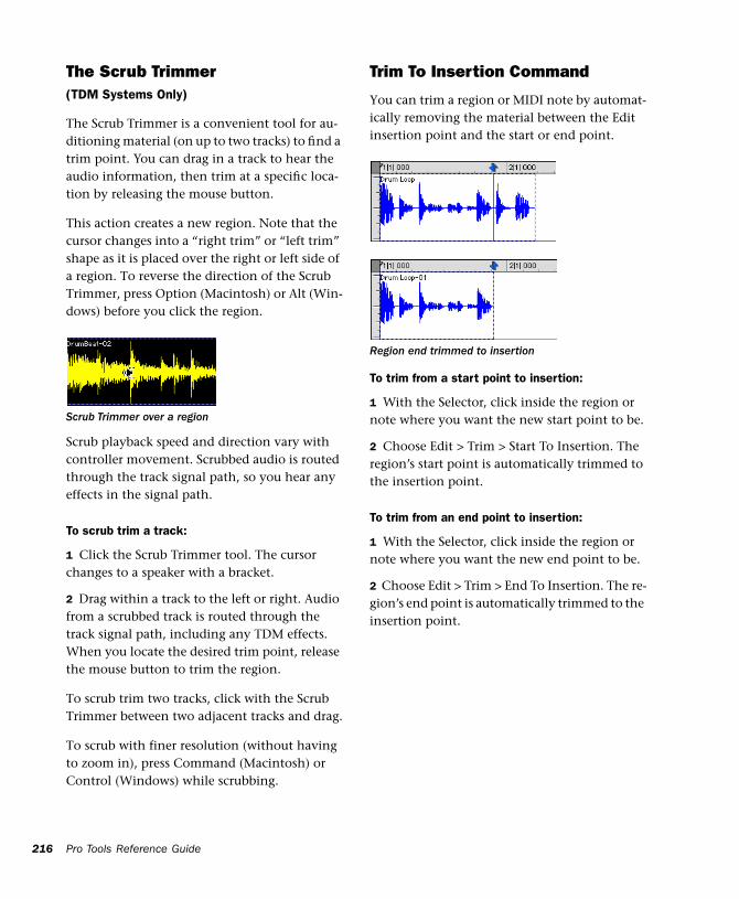
216
The Scrub Trimmer(TDM Systems Only)
The Scrub Trimmer is a convenient tool for au-ditioning material (on up to two tracks) to find a trim point. You can drag in a track to hear the audio information, then trim at a specific loca-tion by releasing the mouse button.
This action creates a new region. Note that the cursor changes into a “right trim” or “left trim” shape as it is placed over the right or left side of a region. To reverse the direction of the Scrub Trimmer, press Option (Macintosh) or Alt (Win-dows) before you click the region.
Scrub playback speed and direction vary with controller movement. Scrubbed audio is routed through the track signal path, so you hear any effects in the signal path.
To scrub trim a track:
1 Click the Scrub Trimmer tool. The cursor changes to a speaker with a bracket.
2 Drag within a track to the left or right. Audio from a scrubbed track is routed through the track signal path, including any TDM effects. When you locate the desired trim point, release the mouse button to trim the region.
To scrub trim two tracks, click with the Scrub Trimmer between two adjacent tracks and drag.
To scrub with finer resolution (without having to zoom in), press Command (Macintosh) or Control (Windows) while scrubbing.
Scrub Trimmer over a region
Pro Tools Reference Guide
Trim To Insertion Command
You can trim a region or MIDI note by automat-ically removing the material between the Edit insertion point and the start or end point.
To trim from a start point to insertion:
1 With the Selector, click inside the region or note where you want the new start point to be.
2 Choose Edit > Trim > Start To Insertion. The region’s start point is automatically trimmed to the insertion point.
To trim from an end point to insertion:
1 With the Selector, click inside the region or note where you want the new end point to be.
2 Choose Edit > Trim > End To Insertion. The re-gion’s end point is automatically trimmed to the insertion point.
Region end trimmed to insertion
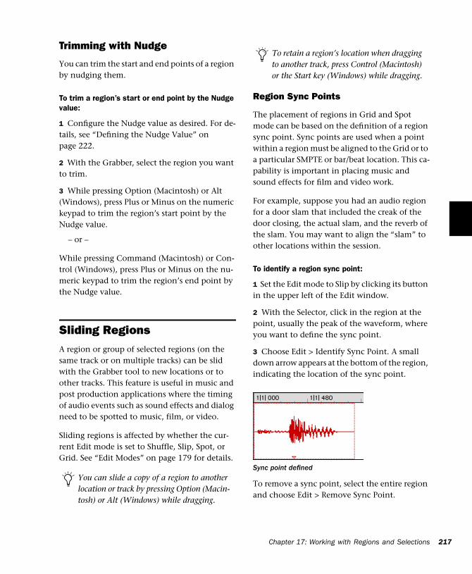
Trimming with Nudge
You can trim the start and end points of a region by nudging them.
To trim a region’s start or end point by the Nudge value:
1 Configure the Nudge value as desired. For de-tails, see “Defining the Nudge Value” on page 222.
2 With the Grabber, select the region you want to trim.
3 While pressing Option (Macintosh) or Alt (Windows), press Plus or Minus on the numeric keypad to trim the region’s start point by the Nudge value.
– or –
While pressing Command (Macintosh) or Con-trol (Windows), press Plus or Minus on the nu-meric keypad to trim the region’s end point by the Nudge value.
Sliding RegionsA region or group of selected regions (on the same track or on multiple tracks) can be slid with the Grabber tool to new locations or to other tracks. This feature is useful in music and post production applications where the timing of audio events such as sound effects and dialog need to be spotted to music, film, or video.
Sliding regions is affected by whether the cur-rent Edit mode is set to Shuffle, Slip, Spot, or Grid. See “Edit Modes” on page 179 for details.
You can slide a copy of a region to another location or track by pressing Option (Macin-tosh) or Alt (Windows) while dragging.
Region Sync Points
The placement of regions in Grid and Spot mode can be based on the definition of a region sync point. Sync points are used when a point within a region must be aligned to the Grid or to a particular SMPTE or bar/beat location. This ca-pability is important in placing music and sound effects for film and video work.
For example, suppose you had an audio region for a door slam that included the creak of the door closing, the actual slam, and the reverb of the slam. You may want to align the “slam” to other locations within the session.
To identify a region sync point:
1 Set the Edit mode to Slip by clicking its button in the upper left of the Edit window.
2 With the Selector, click in the region at the point, usually the peak of the waveform, where you want to define the sync point.
3 Choose Edit > Identify Sync Point. A small down arrow appears at the bottom of the region, indicating the location of the sync point.
To remove a sync point, select the entire region and choose Edit > Remove Sync Point.
To retain a region’s location when dragging to another track, press Control (Macintosh) or the Start key (Windows) while dragging.
Sync point defined
Chapter 17: Working with Regions and Selections 217
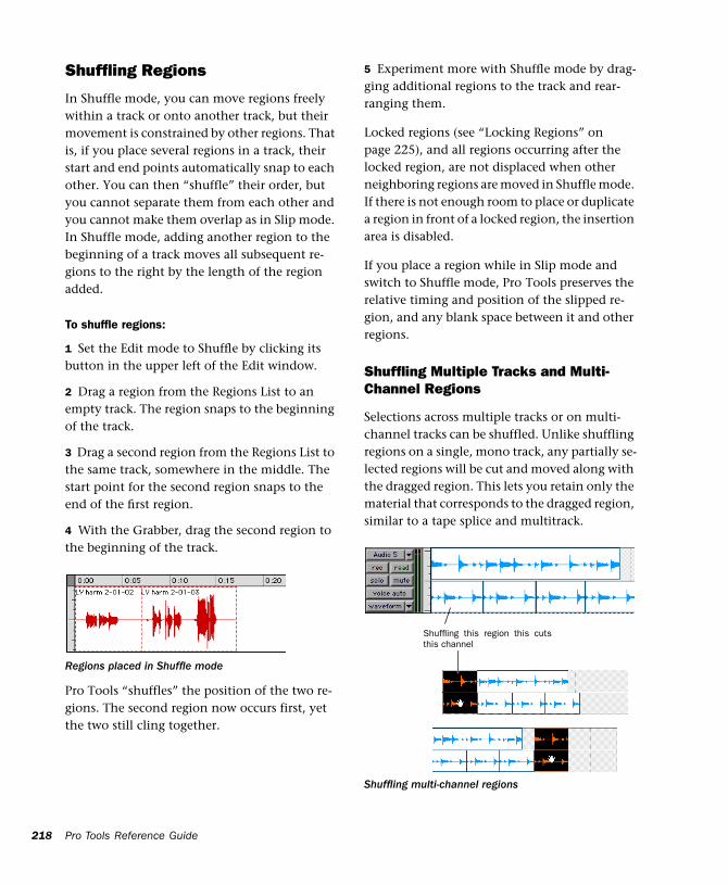
218
Shuffling Regions
In Shuffle mode, you can move regions freely within a track or onto another track, but their movement is constrained by other regions. That is, if you place several regions in a track, their start and end points automatically snap to each other. You can then “shuffle” their order, but you cannot separate them from each other and you cannot make them overlap as in Slip mode. In Shuffle mode, adding another region to the beginning of a track moves all subsequent re-gions to the right by the length of the region added.
To shuffle regions:
1 Set the Edit mode to Shuffle by clicking its button in the upper left of the Edit window.
2 Drag a region from the Regions List to an empty track. The region snaps to the beginning of the track.
3 Drag a second region from the Regions List to the same track, somewhere in the middle. The start point for the second region snaps to the end of the first region.
4 With the Grabber, drag the second region to the beginning of the track.
Pro Tools “shuffles” the position of the two re-gions. The second region now occurs first, yet the two still cling together.
Regions placed in Shuffle mode
Pro Tools Reference Guide
5 Experiment more with Shuffle mode by drag-ging additional regions to the track and rear-ranging them.
Locked regions (see “Locking Regions” on page 225), and all regions occurring after the locked region, are not displaced when other neighboring regions are moved in Shuffle mode. If there is not enough room to place or duplicate a region in front of a locked region, the insertion area is disabled.
If you place a region while in Slip mode and switch to Shuffle mode, Pro Tools preserves the relative timing and position of the slipped re-gion, and any blank space between it and other regions.
Shuffling Multiple Tracks and Multi-Channel Regions
Selections across multiple tracks or on multi-channel tracks can be shuffled. Unlike shuffling regions on a single, mono track, any partially se-lected regions will be cut and moved along with the dragged region. This lets you retain only the material that corresponds to the dragged region, similar to a tape splice and multitrack.
Shuffling multi-channel regions
Shuffling this region this cutsthis channel
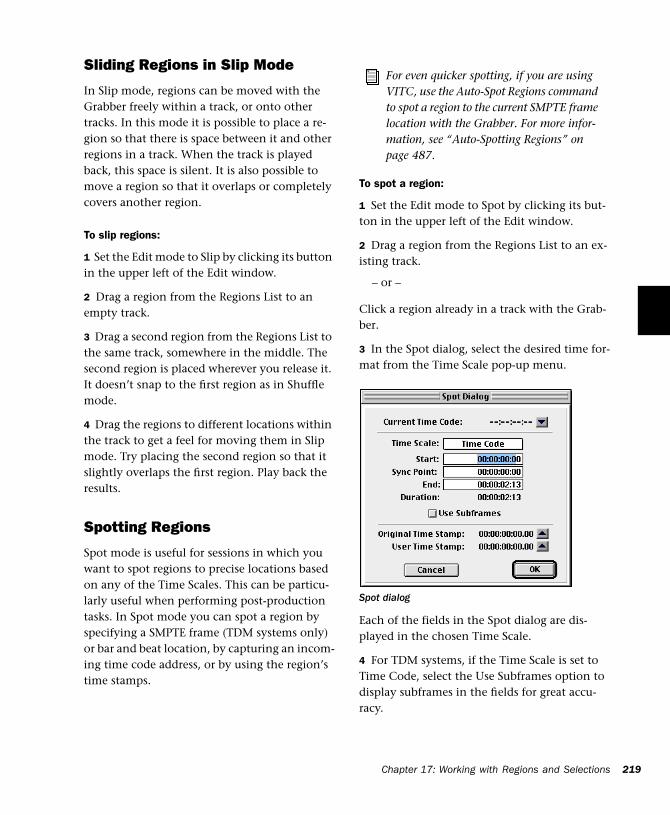
Sliding Regions in Slip Mode
In Slip mode, regions can be moved with the Grabber freely within a track, or onto other tracks. In this mode it is possible to place a re-gion so that there is space between it and other regions in a track. When the track is played back, this space is silent. It is also possible to move a region so that it overlaps or completely covers another region.
To slip regions:
1 Set the Edit mode to Slip by clicking its button in the upper left of the Edit window.
2 Drag a region from the Regions List to an empty track.
3 Drag a second region from the Regions List to the same track, somewhere in the middle. The second region is placed wherever you release it. It doesn’t snap to the first region as in Shuffle mode.
4 Drag the regions to different locations within the track to get a feel for moving them in Slip mode. Try placing the second region so that it slightly overlaps the first region. Play back the results.
Spotting Regions
Spot mode is useful for sessions in which you want to spot regions to precise locations based on any of the Time Scales. This can be particu-larly useful when performing post-production tasks. In Spot mode you can spot a region by specifying a SMPTE frame (TDM systems only) or bar and beat location, by capturing an incom-ing time code address, or by using the region’s time stamps.
To spot a region:
1 Set the Edit mode to Spot by clicking its but-ton in the upper left of the Edit window.
2 Drag a region from the Regions List to an ex-isting track.
– or –
Click a region already in a track with the Grab-ber.
3 In the Spot dialog, select the desired time for-mat from the Time Scale pop-up menu.
Each of the fields in the Spot dialog are dis-played in the chosen Time Scale.
4 For TDM systems, if the Time Scale is set to Time Code, select the Use Subframes option to display subframes in the fields for great accu-racy.
For even quicker spotting, if you are using VITC, use the Auto-Spot Regions command to spot a region to the current SMPTE frame location with the Grabber. For more infor-mation, see “Auto-Spotting Regions” on page 487.
Spot dialog
Chapter 17: Working with Regions and Selections 219
220
5 Click in the field for Start, Sync Point, or End and type in a new location.
– or –
6 Click one of the up arrows next to Original Time Stamp or User Time Stamp to enter the as-sociated values into the currently selected field.
– or –
7 If you are using an external SMPTE time code source, click the down arrow next to the Current Time Code display (or press Equal (=) on the nu-meric keypad) to capture an incoming time code address.
8 Click OK. The region is moved to the new lo-cation specified for its start or sync point.
If a region does not have a sync point defined, the Sync Point field in the Spot dialog functions the same as the Start field.
To learn more about using SMPTE with Pro Tools, refer to Chapter 35, “Time Code Syn-chronization.”
Region Time Stamps
When a region is created, it is time stamped rel-ative to the SMPTE start time specified for the session. This Original Time Stamp is perma-nently stored with the region and cannot be changed. If a region is ever moved, it can easily be placed at its original position from the Spot dialog.
When the Original Time Stamp for a region is initially set, this same location is also used to de-fine the region’s User Time Stamp.
Pro Tools Reference Guide
Unlike the Original Time Stamp, the User Time Stamp can be redefined with the Time Stamp Se-lected command in the Regions List pop-up menu. For more information, see “Time Stamp-ing” on page 488.
Regions with identical User Time Stamps appear together in the Takes List pop-up when audi-tioning takes. For more information, see “Audi-tioning from the Takes List Pop-up Menu” on page 134.
Sliding Regions in Grid Mode
In Grid mode, the movement and placement of regions is constrained to the current Grid value. Grid boundaries, depending on the Main Time Scale, can be based on frames, bar and beat val-ues, minutes or seconds, or a number of sam-ples.
This mode is especially useful for lining up re-gions at precise intervals, as when working with a session that is bar/beat based. For example, if the Grid value is set to quarter-notes (0|1|000), dragging a region to a new location causes it to snap to the nearest quarter-note boundary.
When the Display Preference for “Draw Grid in Edit Window” is enabled, vertical Grid lines ap-pear in the Edit window.
Grid lines in the Edit window can also be en-abled and disabled by Control-clicking (Macin-tosh) or Right-clicking (Windows) the Indicator Dot for any Timebase Ruler.
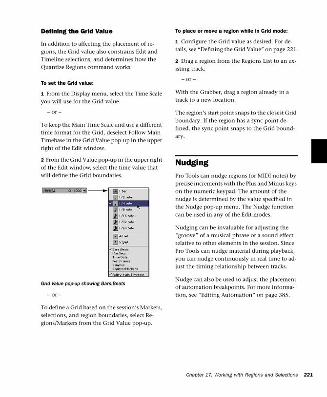
Defining the Grid Value
In addition to affecting the placement of re-gions, the Grid value also constrains Edit and Timeline selections, and determines how the Quantize Regions command works.
To set the Grid value:
1 From the Display menu, select the Time Scale you will use for the Grid value.
– or –
To keep the Main Time Scale and use a different time format for the Grid, deselect Follow Main Timebase in the Grid Value pop-up in the upper right of the Edit window.
2 From the Grid Value pop-up in the upper right of the Edit window, select the time value that will define the Grid boundaries.
– or –
To define a Grid based on the session’s Markers, selections, and region boundaries, select Re-gions/Markers from the Grid Value pop-up.
Grid Value pop-up showing Bars:Beats
To place or move a region while in Grid mode:
1 Configure the Grid value as desired. For de-tails, see “Defining the Grid Value” on page 221.
2 Drag a region from the Regions List to an ex-isting track.
– or –
With the Grabber, drag a region already in a track to a new location.
The region’s start point snaps to the closest Grid boundary. If the region has a sync point de-fined, the sync point snaps to the Grid bound-ary.
Nudging Pro Tools can nudge regions (or MIDI notes) by precise increments with the Plus and Minus keys on the numeric keypad. The amount of the nudge is determined by the value specified in the Nudge pop-up menu. The Nudge function can be used in any of the Edit modes.
Nudging can be invaluable for adjusting the “groove” of a musical phrase or a sound effect relative to other elements in the session. Since Pro Tools can nudge material during playback, you can nudge continuously in real time to ad-just the timing relationship between tracks.
Nudge can also be used to adjust the placement of automation breakpoints. For more informa-tion, see “Editing Automation” on page 385.
Chapter 17: Working with Regions and Selections 221
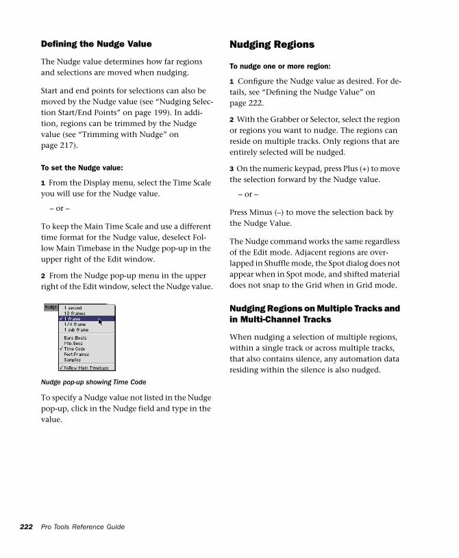
222
Defining the Nudge Value
The Nudge value determines how far regions and selections are moved when nudging.
Start and end points for selections can also be moved by the Nudge value (see “Nudging Selec-tion Start/End Points” on page 199). In addi-tion, regions can be trimmed by the Nudge value (see “Trimming with Nudge” on page 217).
To set the Nudge value:
1 From the Display menu, select the Time Scale you will use for the Nudge value.
– or –
To keep the Main Time Scale and use a different time format for the Nudge value, deselect Fol-low Main Timebase in the Nudge pop-up in the upper right of the Edit window.
2 From the Nudge pop-up menu in the upper right of the Edit window, select the Nudge value.
To specify a Nudge value not listed in the Nudge pop-up, click in the Nudge field and type in the value.
Nudge pop-up showing Time Code
Pro Tools Reference Guide
Nudging Regions
To nudge one or more region:
1 Configure the Nudge value as desired. For de-tails, see “Defining the Nudge Value” on page 222.
2 With the Grabber or Selector, select the region or regions you want to nudge. The regions can reside on multiple tracks. Only regions that are entirely selected will be nudged.
3 On the numeric keypad, press Plus (+) to move the selection forward by the Nudge value.
– or –
Press Minus (–) to move the selection back by the Nudge Value.
The Nudge command works the same regardless of the Edit mode. Adjacent regions are over-lapped in Shuffle mode, the Spot dialog does not appear when in Spot mode, and shifted material does not snap to the Grid when in Grid mode.
Nudging Regions on Multiple Tracks and in Multi-Channel Tracks
When nudging a selection of multiple regions, within a single track or across multiple tracks, that also contains silence, any automation data residing within the silence is also nudged.
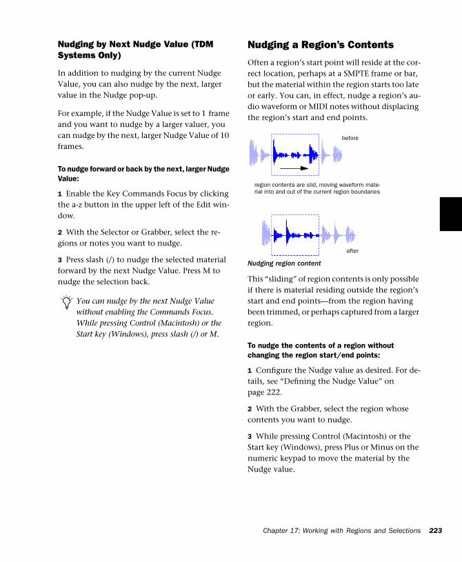
Nudging by Next Nudge Value (TDM Systems Only)
In addition to nudging by the current Nudge Value, you can also nudge by the next, larger value in the Nudge pop-up.
For example, if the Nudge Value is set to 1 frame and you want to nudge by a larger valuer, you can nudge by the next, larger Nudge Value of 10 frames.
To nudge forward or back by the next, larger Nudge Value:
1 Enable the Key Commands Focus by clicking the a-z button in the upper left of the Edit win-dow.
2 With the Selector or Grabber, select the re-gions or notes you want to nudge.
3 Press slash (/) to nudge the selected material forward by the next Nudge Value. Press M to nudge the selection back.
You can nudge by the next Nudge Value without enabling the Commands Focus. While pressing Control (Macintosh) or the Start key (Windows), press slash (/) or M.
Nudging a Region’s Contents
Often a region’s start point will reside at the cor-rect location, perhaps at a SMPTE frame or bar, but the material within the region starts too late or early. You can, in effect, nudge a region’s au-dio waveform or MIDI notes without displacing the region’s start and end points.
This “sliding” of region contents is only possible if there is material residing outside the region’s start and end points—from the region having been trimmed, or perhaps captured from a larger region.
To nudge the contents of a region without changing the region start/end points:
1 Configure the Nudge value as desired. For de-tails, see “Defining the Nudge Value” on page 222.
2 With the Grabber, select the region whose contents you want to nudge.
3 While pressing Control (Macintosh) or the Start key (Windows), press Plus or Minus on the numeric keypad to move the material by the Nudge value.
Nudging region content
region contents are slid, moving waveform mate-rial into and out of the current region boundaries
before
after
Chapter 17: Working
w ith Regions and Selections 223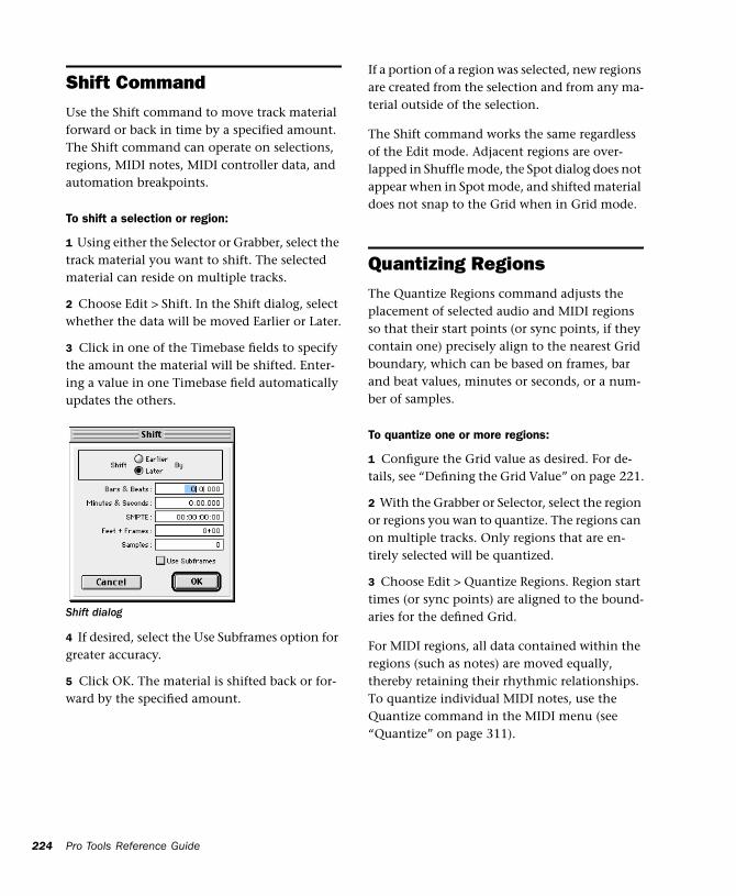
224
Shift CommandUse the Shift command to move track material forward or back in time by a specified amount. The Shift command can operate on selections, regions, MIDI notes, MIDI controller data, and automation breakpoints.
To shift a selection or region:
1 Using either the Selector or Grabber, select the track material you want to shift. The selected material can reside on multiple tracks.
2 Choose Edit > Shift. In the Shift dialog, select whether the data will be moved Earlier or Later.
3 Click in one of the Timebase fields to specify the amount the material will be shifted. Enter-ing a value in one Timebase field automatically updates the others.
4 If desired, select the Use Subframes option for greater accuracy.
5 Click OK. The material is shifted back or for-ward by the specified amount.
Shift dialog
Pro Tools Reference Guide
If a portion of a region was selected, new regions are created from the selection and from any ma-terial outside of the selection.
The Shift command works the same regardless of the Edit mode. Adjacent regions are over-lapped in Shuffle mode, the Spot dialog does not appear when in Spot mode, and shifted material does not snap to the Grid when in Grid mode.
Quantizing RegionsThe Quantize Regions command adjusts the placement of selected audio and MIDI regions so that their start points (or sync points, if they contain one) precisely align to the nearest Grid boundary, which can be based on frames, bar and beat values, minutes or seconds, or a num-ber of samples.
To quantize one or more regions:
1 Configure the Grid value as desired. For de-tails, see “Defining the Grid Value” on page 221.
2 With the Grabber or Selector, select the region or regions you wan to quantize. The regions can on multiple tracks. Only regions that are en-tirely selected will be quantized.
3 Choose Edit > Quantize Regions. Region start times (or sync points) are aligned to the bound-aries for the defined Grid.
For MIDI regions, all data contained within the regions (such as notes) are moved equally, thereby retaining their rhythmic relationships. To quantize individual MIDI notes, use the Quantize command in the MIDI menu (see “Quantize” on page 311).
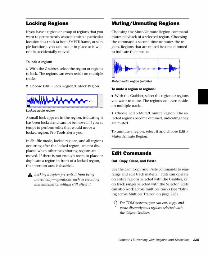
Locking RegionsIf you have a region or group of regions that you want to permanently associate with a particular location in a track (a beat, SMPTE frame, or sam-ple location), you can lock it in place so it will not be accidentally moved.
To lock a region:
1 With the Grabber, select the region or regions to lock. The regions can even reside on multiple tracks.
2 Choose Edit > Lock Region/Unlock Region.
A small lock appears in the region, indicating it has been locked and cannot be moved. If you at-tempt to perform edits that would move a locked region, Pro Tools alerts you.
In Shuffle mode, locked regions, and all regions occurring after the locked region, are not dis-placed when other neighboring regions are moved. If there is not enough room to place or duplicate a region in front of a locked region, the insertion area is disabled.
Locked audio region
Locking a region prevents it from being moved only—operations such as recording and automation editing still affect it.
Muting/Unmuting RegionsChoosing the Mute/Unmute Region command mutes playback of a selected region. Choosing the command a second time unmutes the re-gion. Regions that are muted become dimmed to indicate their status.
To mute a region or regions:
1 With the Grabber, select the region or regions you want to mute. The regions can even reside on multiple tracks.
2 Choose Edit > Mute/Unmute Region. The se-lected regions become dimmed, indicating they are muted.
To unmute a region, select it and choose Edit > Mute/Unmute Region.
Edit CommandsCut, Copy, Clear, and Paste
Use the Cut, Copy and Paste commands to rear-range and edit track material. Edits can operate on entire regions selected with the Grabber, or on track ranges selected with the Selector. Edits can also work across multiple tracks (see “Edit-ing across Multiple Tracks” on page 228).
Muted audio region (middle)
For TDM systems, you can cut, copy, and paste discontiguous regions selected with the Object Grabber.
Chapter 17: Working with Regions and Selections 225
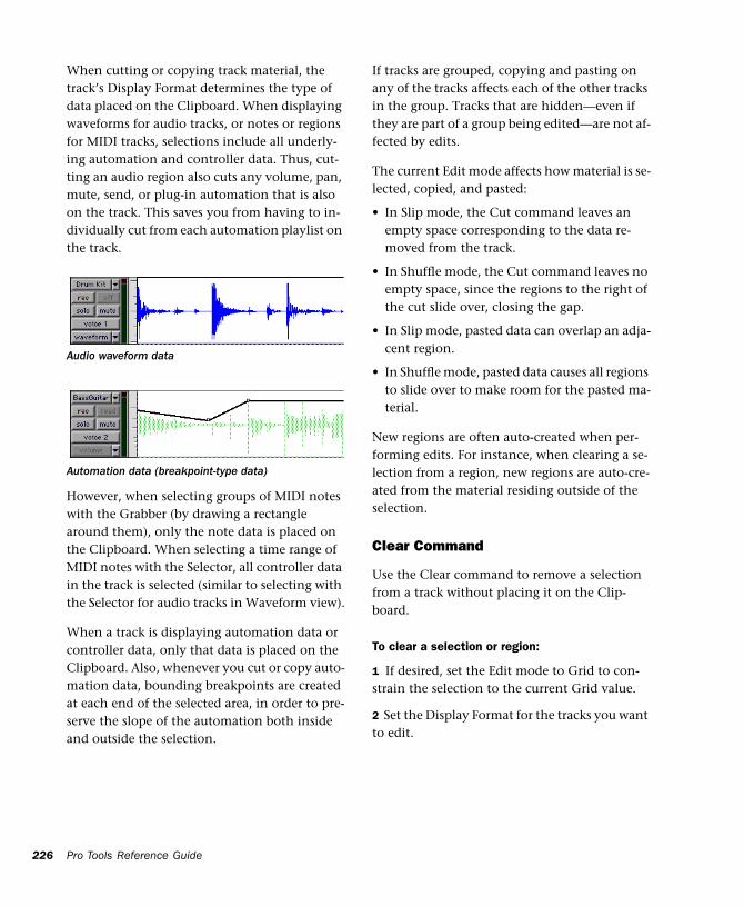
226
When cutting or copying track material, the track’s Display Format determines the type of data placed on the Clipboard. When displaying waveforms for audio tracks, or notes or regions for MIDI tracks, selections include all underly-ing automation and controller data. Thus, cut-ting an audio region also cuts any volume, pan, mute, send, or plug-in automation that is also on the track. This saves you from having to in-dividually cut from each automation playlist on the track.
However, when selecting groups of MIDI notes with the Grabber (by drawing a rectangle around them), only the note data is placed on the Clipboard. When selecting a time range of MIDI notes with the Selector, all controller data in the track is selected (similar to selecting with the Selector for audio tracks in Waveform view).
When a track is displaying automation data or controller data, only that data is placed on the Clipboard. Also, whenever you cut or copy auto-mation data, bounding breakpoints are created at each end of the selected area, in order to pre-serve the slope of the automation both inside and outside the selection.
Audio waveform data
Automation data (breakpoint-type data)
Pro Tools Reference Guide
If tracks are grouped, copying and pasting on any of the tracks affects each of the other tracks in the group. Tracks that are hidden—even if they are part of a group being edited—are not af-fected by edits.
The current Edit mode affects how material is se-lected, copied, and pasted:
• In Slip mode, the Cut command leaves an empty space corresponding to the data re-moved from the track.
• In Shuffle mode, the Cut command leaves no empty space, since the regions to the right of the cut slide over, closing the gap.
• In Slip mode, pasted data can overlap an adja-cent region.
• In Shuffle mode, pasted data causes all regions to slide over to make room for the pasted ma-terial.
New regions are often auto-created when per-forming edits. For instance, when clearing a se-lection from a region, new regions are auto-cre-ated from the material residing outside of the selection.
Clear Command
Use the Clear command to remove a selection from a track without placing it on the Clip-board.
To clear a selection or region:
1 If desired, set the Edit mode to Grid to con-strain the selection to the current Grid value.
2 Set the Display Format for the tracks you want to edit.
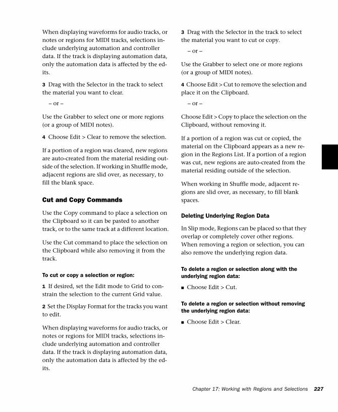
When displaying waveforms for audio tracks, or notes or regions for MIDI tracks, selections in-clude underlying automation and controller data. If the track is displaying automation data, only the automation data is affected by the ed-its.
3 Drag with the Selector in the track to select the material you want to clear.
– or –
Use the Grabber to select one or more regions (or a group of MIDI notes).
4 Choose Edit > Clear to remove the selection.
If a portion of a region was cleared, new regions are auto-created from the material residing out-side of the selection. If working in Shuffle mode, adjacent regions are slid over, as necessary, to fill the blank space.
Cut and Copy Commands
Use the Copy command to place a selection on the Clipboard so it can be pasted to another track, or to the same track at a different location.
Use the Cut command to place the selection on the Clipboard while also removing it from the track.
To cut or copy a selection or region:
1 If desired, set the Edit mode to Grid to con-strain the selection to the current Grid value.
2 Set the Display Format for the tracks you want to edit.
When displaying waveforms for audio tracks, or notes or regions for MIDI tracks, selections in-clude underlying automation and controller data. If the track is displaying automation data, only the automation data is affected by the ed-its.
3 Drag with the Selector in the track to select the material you want to cut or copy.
– or –
Use the Grabber to select one or more regions (or a group of MIDI notes).
4 Choose Edit > Cut to remove the selection and place it on the Clipboard.
– or –
Choose Edit > Copy to place the selection on the Clipboard, without removing it.
If a portion of a region was cut or copied, the material on the Clipboard appears as a new re-gion in the Regions List. If a portion of a region was cut, new regions are auto-created from the material residing outside of the selection.
When working in Shuffle mode, adjacent re-gions are slid over, as necessary, to fill blank spaces.
Deleting Underlying Region Data
In Slip mode, Regions can be placed so that they overlap or completely cover other regions. When removing a region or selection, you can also remove the underlying region data.
To delete a region or selection along with the underlying region data:
■ Choose Edit > Cut.
To delete a region or selection without removing the underlying region data:
■ Choose Edit > Clear.
Chapter 17: Working with Regions and Selections 227
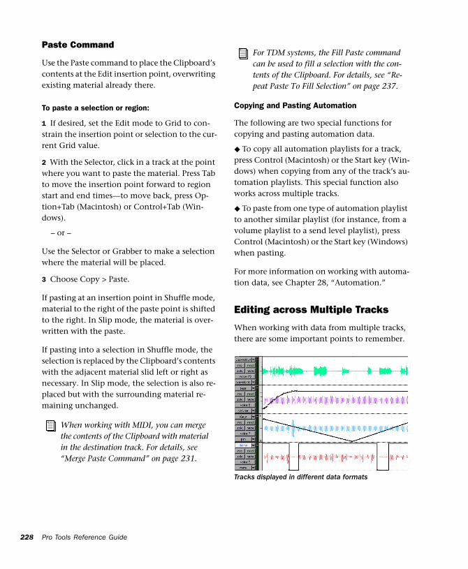
228
Paste Command
Use the Paste command to place the Clipboard’s contents at the Edit insertion point, overwriting existing material already there.
To paste a selection or region:
1 If desired, set the Edit mode to Grid to con-strain the insertion point or selection to the cur-rent Grid value.
2 With the Selector, click in a track at the point where you want to paste the material. Press Tab to move the insertion point forward to region start and end times—to move back, press Op-tion+Tab (Macintosh) or Control+Tab (Win-dows).
– or –
Use the Selector or Grabber to make a selection where the material will be placed.
3 Choose Copy > Paste.
If pasting at an insertion point in Shuffle mode, material to the right of the paste point is shifted to the right. In Slip mode, the material is over-written with the paste.
If pasting into a selection in Shuffle mode, the selection is replaced by the Clipboard’s contents with the adjacent material slid left or right as necessary. In Slip mode, the selection is also re-placed but with the surrounding material re-maining unchanged.
When working with MIDI, you can merge the contents of the Clipboard with material in the destination track. For details, see “Merge Paste Command” on page 231.
Pro Tools Reference Guide
Copying and Pasting Automation
The following are two special functions for copying and pasting automation data.
◆ To copy all automation playlists for a track, press Control (Macintosh) or the Start key (Win-dows) when copying from any of the track’s au-tomation playlists. This special function also works across multiple tracks.
◆ To paste from one type of automation playlist to another similar playlist (for instance, from a volume playlist to a send level playlist), press Control (Macintosh) or the Start key (Windows) when pasting.
For more information on working with automa-tion data, see Chapter 28, “Automation.”
Editing across Multiple Tracks
When working with data from multiple tracks, there are some important points to remember.
For TDM systems, the Fill Paste command can be used to fill a selection with the con-tents of the Clipboard. For details, see “Re-peat Paste To Fill Selection” on page 237.
Tracks displayed in different data formats
For instance, if any of the selected tracks are set to display audio or MIDI regions (or MIDI notes), edits affect not only MIDI and audio for the selected tracks, but all automation and con-troller data as well.
If all selected tracks are displayed as automation data, edits only affect the type of automation data displayed in each track. Thus, if track 1 dis-plays Pan automation, track 2 displays Volume automation, and track 3 displays Mute automa-tion, the Cut command cuts only pan data from track 1, volume data from track 2, and mute data from track 3.
When copying only automation or controller data for selected tracks, press Control (Macin-tosh) or the Start key (Windows) to copy all types of automation on all selected tracks.
To paste to multiple tracks, place the insertion point in each of the destination tracks by Shift-clicking in them—or to select all tracks, Option-Shift-click (Macintosh) or Alt-Shift-click (Win-dows) in a track, or make a selection in one of the Timebase Rulers.
When you paste multiple types of data, what-ever data has been copied is pasted into the cor-rect type of playlist. Automation data is pasted into the appropriate automation playlist (pan, volume, mute and so on). Audio/MIDI data is pasted into the audio/MIDI playlist. You don’t need to set target tracks to the specific type of data being pasted for the paste to work correctly.
If all destination tracks in a multitrack paste are displayed as automation, the paste replaces any previous data on the target track without shuf-fling—regardless of whether you are in Slip or Shuffle mode.
For details on selecting data on multiple tracks, see “Selecting Across Multiple Tracks” on page 201.
Duplicate CommandThe Duplicate command copies a selection and places it immediately after the end of the selec-tion. Though this is similar to using Copy and Paste, Duplicate is more convenient and faster, particularly when working with data on multi-ple tracks.
To make more than one copy of a selection, use the Repeat command (see “Repeat Command” on page 230).
As with the Copy and Paste commands, certain rules apply when duplicating material on multi-ple tracks. For details, see “Editing across Multi-ple Tracks” on page 228.
To duplicate a selection or region:
1 If working with material that is bar- and beat-based, such as loops, set the Main Time Scale to Bars:Beats.
2 If desired, set the Edit mode to Grid to con-strain the selection to the current Grid value.
3 Drag with the Selector in the track to select the material you want to duplicate.
– or –
Click in the track and enter the start and end points for the selection in the Event Edit area.
4 Choose Edit > Duplicate. The material is placed immediately after the selection’s end point.
The Duplicate command does not operate on conductor events.
Chapter 17: Working with Regions and Selections 229
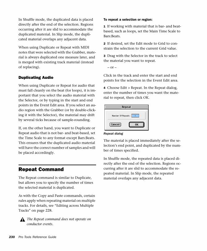
230
In Shuffle mode, the duplicated data is placed directly after the end of the selection. Regions occurring after it are slid to accommodate the duplicated material. In Slip mode, the dupli-cated material overlaps any adjacent data.
When using Duplicate or Repeat with MIDI notes that were selected with the Grabber, mate-rial is always duplicated one measure later, and is merged with existing track material (instead of replacing).
Duplicating Audio
When using Duplicate or Repeat for audio that must fall cleanly on the beat (for loops), it is im-portant that you select the audio material with the Selector, or by typing in the start and end points in the Event Edit area. If you select an au-dio region with the Grabber (or by double-click-ing it with the Selector), the material may drift by several ticks because of sample-rounding.
If, on the other hand, you want to Duplicate or Repeat audio that is not bar- and beat-based, set the Time Scale to any format except Bars:Beats. This ensures that the duplicated audio material will have the correct number of samples and will be placed accordingly.
Repeat CommandThe Repeat command is similar to Duplicate, but allows you to specify the number of times the selected material is duplicated.
As with the Copy and Paste commands, certain rules apply when repeating material on multiple tracks. For details, see “Editing across Multiple Tracks” on page 228.
The Repeat command does not operate on conductor events.
Pro Tools Reference Guide
To repeat a selection or region:
1 If working with material that is bar- and beat-based, such as loops, set the Main Time Scale to Bars:Beats.
2 If desired, set the Edit mode to Grid to con-strain the selection to the current Grid value.
3 Drag with the Selector in the track to select the material you want to repeat.
– or –
Click in the track and enter the start and end points for the selection in the Event Edit area.
4 Choose Edit > Repeat. In the Repeat dialog, enter the number of times you want the mate-rial to repeat, then click OK.
The material is placed immediately after the se-lection’s end point, and duplicated by the num-ber of times specified.
In Shuffle mode, the repeated data is placed di-rectly after the end of the selection. Regions oc-curring after it are slid to accommodate the re-peated material. In Slip mode, the repeated material overlaps any adjacent data.
Repeat dialog
Merge Paste Command(MIDI Only)
Use the Merge Paste command to merge MIDI notes from the Clipboard with material already residing in the paste destination. To replace track material, use the Paste command instead.
To merge MIDI data:
1 If desired, set the Edit mode to Grid to con-strain the selection to the current Grid value.
2 Drag with the Selector in the track to select the MIDI notes you want to merge.
– or –
Use the Grabber to select one or more MIDI re-gions (or a group of MIDI notes).
3 Choose Edit > Cut to remove the selection and place it on the Clipboard.
– or –
Choose Edit > Copy to place the selection on the Clipboard without removing it.
4 With the Selector, click in a MIDI track at the point where you want to merge the material.
5 Choose Edit > Merge Paste. The Clipboard’s contents are pasted at the insertion point, with-out removing the existing material already re-siding there.
If any portion of the material is pasted outside of existing regions, a new region is created for the data.
Editing Stereo and Multi-Channel TracksRegions on individual channels within stereo and multi-channel tracks cannot be indepen-dently selected. All selections for these tracks are time based, which means that selections made with the Selector and Grabber extend to each channel in the track.
When regions in multi-channel tracks are edited with the Trimmer or dragged with the Grabber, material on all channels is affected equally as a group.
Split Selected Tracks
To edit a specific channel within a stereo or multi-channel track without affecting the other channels, you can split the track into separate mono tracks. Once the desired edits have been made to the separated material, you can then drag or copy it back to the original multi-chan-nel track.
To split a stereo or multi-channel track:
1 Select the track you want to split by clicking its name in the Edit or Mix window. To split multiple tracks, Shift-click additional tracks.
2 Choose File > Split Selected Tracks Into Mono. Regions from the channels on the selected tracks are placed on new, mono audio tracks.
Names for the new tracks are based on the source track name and channel suffix. For exam-ple, if a stereo track called “Funkit” is split, two new tracks called “Funkit.L” and “Funkit.R” are created.
Chapter 17: Working with Regions and Selections 231
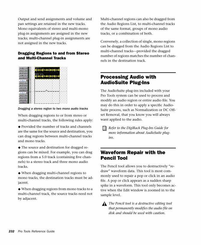
232
Output and send assignments and volume and pan settings are retained in the new tracks. Mono equivalents of stereo and multi-mono plug-in assignments are assigned in the new tracks; multi-channel plug-in assignments are not assigned in the new tracks.
Dragging Regions to and from Stereo and Multi-Channel Tracks
When dragging regions to or from stereo or multi-channel tracks, the following rules apply:
◆ Provided the number of tracks and channels are the same for the source and destination, you can drag regions between multi-channel tracks and mono tracks.
◆ The source and destination for dragged re-gions can be mixed. For example, you can drag regions from a 5.0 track (containing five chan-nels) to a stereo track and three mono audio tracks.
◆ When dragging multi-channel regions to mono tracks, the destination tracks must be ad-jacent.
◆ When dragging regions from mono tracks to a multi-channel track, the source tracks need not by adjacent.
Dragging a stereo region to two mono audio tracks
Pro Tools Reference Guide
Multi-channel regions can also be dragged from the Audio Regions List, to multi-channel tracks of the same format, groups of mono audio tracks, or a combination of both.
Conversely, a collection of single, mono regions can be dragged from the Audio Regions List to multi-channel tracks—provided the dragged number of regions matches the number of chan-nels in the destination track.
Processing Audio with AudioSuite Plug-InsThe AudioSuite plug-ins included with your Pro Tools system can be used to process and modify an audio region or entire audio file. You may do this in order to apply a specific Audio-Suite process, such as Normalization or DC Off-set Removal, that you know you will always want applied to the audio.
Waveform Repair with the Pencil ToolThe Pencil tool allows you to destructively “re-draw” waveform data. This tool is most com-monly used to repair a pop or click in an audio file. A pop or click appears as a sudden sharp spike in a waveform. This tool only becomes ac-tive when the Edit window is zoomed in to the sample level.
Refer to the DigiRack Plug-Ins Guide for more information about AudioSuite plug-ins.
The Pencil tool is a destructive editing tool that permanently modifies the audio file on disk and should be used with caution.
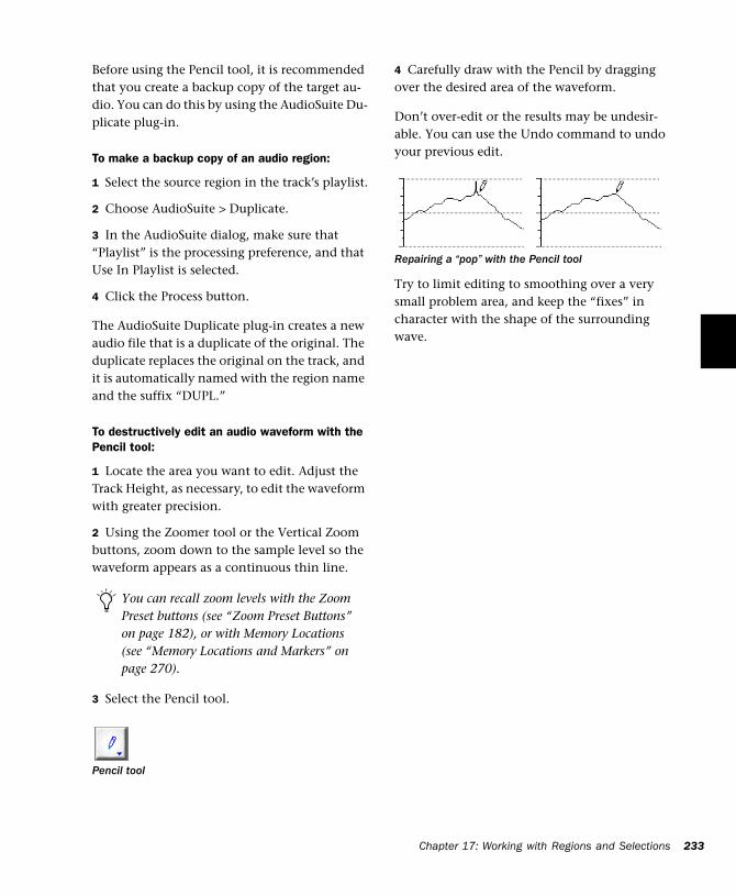
Before using the Pencil tool, it is recommended that you create a backup copy of the target au-dio. You can do this by using the AudioSuite Du-plicate plug-in.
To make a backup copy of an audio region:
1 Select the source region in the track’s playlist.
2 Choose AudioSuite > Duplicate.
3 In the AudioSuite dialog, make sure that “Playlist” is the processing preference, and that Use In Playlist is selected.
4 Click the Process button.
The AudioSuite Duplicate plug-in creates a new audio file that is a duplicate of the original. The duplicate replaces the original on the track, and it is automatically named with the region name and the suffix “DUPL.”
To destructively edit an audio waveform with the Pencil tool:
1 Locate the area you want to edit. Adjust the Track Height, as necessary, to edit the waveform with greater precision.
2 Using the Zoomer tool or the Vertical Zoom buttons, zoom down to the sample level so the waveform appears as a continuous thin line.
3 Select the Pencil tool.
You can recall zoom levels with the Zoom Preset buttons (see “Zoom Preset Buttons” on page 182), or with Memory Locations (see “Memory Locations and Markers” on page 270).
Pencil tool
4 Carefully draw with the Pencil by dragging over the desired area of the waveform.
Don’t over-edit or the results may be undesir-able. You can use the Undo command to undo your previous edit.
Try to limit editing to smoothing over a very small problem area, and keep the “fixes” in character with the shape of the surrounding wave.
Repairing a “pop” with the Pencil tool
Chapter 17: Working with Regions and Selections 233

234
Pro Tools Reference Guide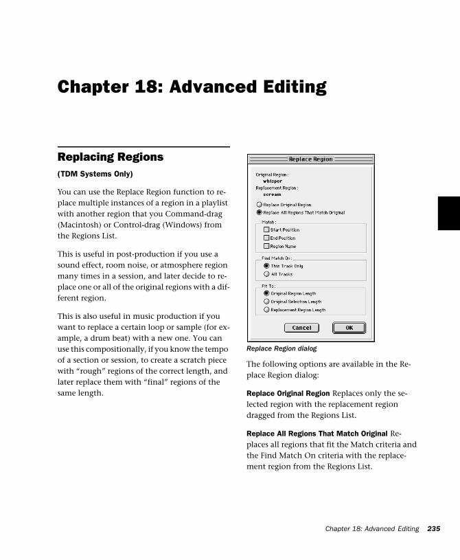
Chapter 18: Advanced Editing
Replacing Regions(TDM Systems Only)
You can use the Replace Region function to re-place multiple instances of a region in a playlist with another region that you Command-drag (Macintosh) or Control-drag (Windows) from the Regions List.
This is useful in post-production if you use a sound effect, room noise, or atmosphere region many times in a session, and later decide to re-place one or all of the original regions with a dif-ferent region.
This is also useful in music production if you want to replace a certain loop or sample (for ex-ample, a drum beat) with a new one. You can use this compositionally, if you know the tempo of a section or session, to create a scratch piece with “rough” regions of the correct length, and later replace them with “final” regions of the same length.
The following options are available in the Re-place Region dialog:
Replace Original Region Replaces only the se-lected region with the replacement region dragged from the Regions List.
Replace All Regions That Match Original Re-places all regions that fit the Match criteria and the Find Match On criteria with the replace-ment region from the Regions List.
Replace Region dialog
Chapter 18: Advanced Editing 235
236
Match: Start Position Replaces all regions that have the same original start time as the selected region. This includes regions that may have been auto-created when trimming end points.
Match: End Position Replaces all regions that have the same original end time as the selected region. This includes regions that may have been auto-created when trimming start points.
Match: Region Name Replaces all regions that have the same name as the selected region.
Region matching uses all specified Match crite-ria. For example, if you select Start Position and End Position, all regions from the same original audio file as your selection with the same origi-nal start and end times will be replaced.
Find Match On: Target Track Replaces regions that fit the Match criteria and are on the same track as the original region.
Find Match On: All Tracks Replaces regions that fit the Match criteria for all tracks in the session.
Fit to: Original Region Length If the replacement region is smaller than the original region, the re-gion is placed in the playlist and any remaining audio from the original region is removed.
If the replacement region is larger than the se-lection, it is placed in the playlist and trimmed to fit within the length of the original region.
Fit to: Original Selection Length When the playl-ist selection extends beyond the original region, the replacement region (if larger than the origi-nal region) is trimmed to fit within the selec-tion.
Pro Tools Reference Guide
Fit to: Replacement Region Length The replace-ment region is placed in its entirety, regardless of the length of the original region or selection.
The Replace Region function only works on a se-lection that includes a single region on one track. The function is not available when the playlist selection includes the start points for two or more regions. Also, if the selection is across several tracks, only the selection in the first (top) track is used.
To replace regions:
1 Select a region in a track’s playlist that you want to replace. If desired, the selection can ex-tend beyond the region’s end point, to include material from the replacement region that is longer than the original region.
2 Command-drag (Macintosh) or Control-drag (Windows) the replacement region from the Re-gions List to the selected region. The Replace Re-gion dialog opens.
3 If you only want to replace only the original region, select Replace Original Region.
– or –
If you want to replace multiple regions, select Replace All Regions That Match Original, and set the Match criteria.
4 Select whether to apply the replacement to all tracks, or only to the track with the current se-lection.
5 Select whether to fit the replacement regions to the current selection, the entire region, or the entire replacement region regardless of the des-tination length.
6 When you have set all the options, click OK.
Replace Region and Multi-Channel Tracks
The Replace Region command supports drag-ging multi-channel regions from the Audio Re-gions List to multi-channel tracks, provided they are the same format.
For example, you can replace a stereo region, se-lected in a stereo audio track, with another ste-reo region from the Audio Regions List. But you cannot replace it with two mono audio regions.
In addition, replacing regions in multiple mono tracks with multi-channel regions is not sup-ported.
Repeat Paste To Fill Selection(TDM Systems Only)
The Repeat Paste To Fill Selection command al-lows you to automatically fill a selection with audio or MIDI data without requiring you to du-plicate the regions manually. To use Repeat Paste, copy an audio or MIDI region, then make a selection and use the command to fill the se-lection. When pasting audio regions, you are prompted to specify a crossfade to be used for the pasted regions.
If you fill an area that is an exact multiple of the copied region size (for example, filling 16 bars with a 4-bar loop), the copied selection is pasted in exactly as many times as it takes to fill the se-lection. If you fill an area that is not an exact multiple of the copied region size (for example, filling 15 seconds of a track with a 2 second at-mosphere or room noise region), the remaining selection area is filled with an automatically trimmed version of the original selection.
To fill a selection with Fill Paste:
1 Select the audio or MIDI region you want to copy and choose Edit > Copy.
2 Select the area you want to fill using the Selec-tor and choose Edit > Repeat Paste To Fill Selec-tion.
3 If pasting audio regions, the Batch Fades dia-log opens. Configure the dialog as desired to in-sert crossfades between each pasted region, then click OK.
– or –
If you do not want crossfades for the pasted au-dio, click Cancel in the Batch Fades dialog.
Compress/Expand Edit To Play(TDM Systems Only)
When the Edit and Timeline selections are un-linked, you can compress or expand an audio se-lection to fit the Timeline selection. This feature works by using the Time Compression/Expan-sion plug-in to expand or compress the selected audio material.
To fit an Edit selection to the Timeline:
1 Deselect Operations > Link Edit and Timeline Selection.
2 With the Selector, select the audio material to be compressed or expanded.
3 In any Timebase Ruler, select the time range where you want to fit the audio material.
4 Choose Edit > Compress/Expand Edit To Play. The Edit selection is compressed or expanded to the length of the Timeline selection.
Chapter 18: Advanced Editing 237
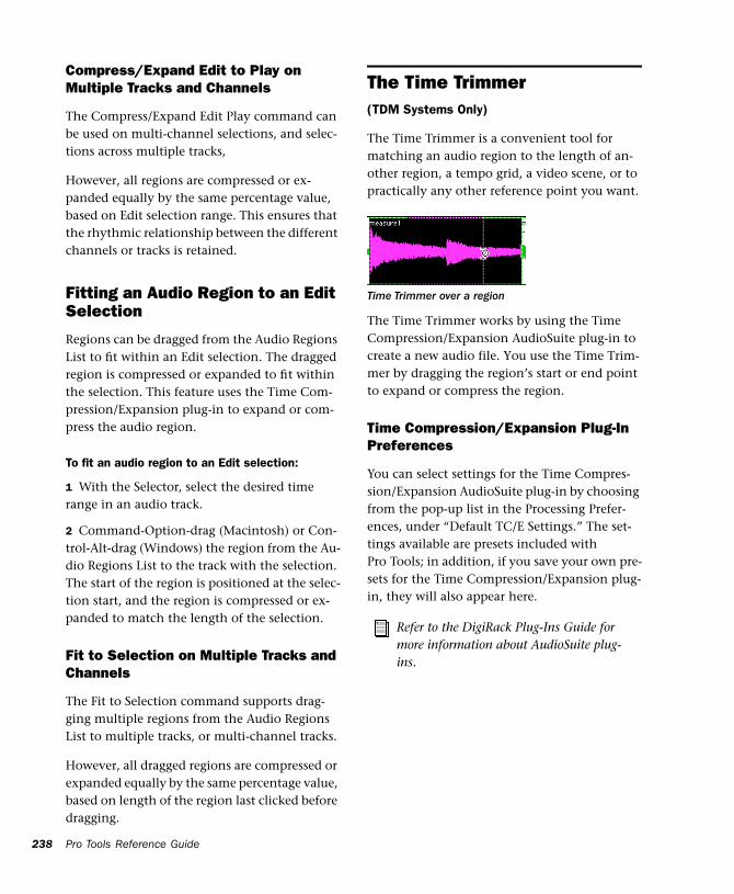
238
Compress/Expand Edit to Play on Multiple Tracks and Channels
The Compress/Expand Edit Play command can be used on multi-channel selections, and selec-tions across multiple tracks,
However, all regions are compressed or ex-panded equally by the same percentage value, based on Edit selection range. This ensures that the rhythmic relationship between the different channels or tracks is retained.
Fitting an Audio Region to an Edit Selection
Regions can be dragged from the Audio Regions List to fit within an Edit selection. The dragged region is compressed or expanded to fit within the selection. This feature uses the Time Com-pression/Expansion plug-in to expand or com-press the audio region.
To fit an audio region to an Edit selection:
1 With the Selector, select the desired time range in an audio track.
2 Command-Option-drag (Macintosh) or Con-trol-Alt-drag (Windows) the region from the Au-dio Regions List to the track with the selection. The start of the region is positioned at the selec-tion start, and the region is compressed or ex-panded to match the length of the selection.
Fit to Selection on Multiple Tracks and Channels
The Fit to Selection command supports drag-ging multiple regions from the Audio Regions List to multiple tracks, or multi-channel tracks.
However, all dragged regions are compressed or expanded equally by the same percentage value, based on length of the region last clicked before dragging.
Pro Tools Reference Guide
The Time Trimmer(TDM Systems Only)
The Time Trimmer is a convenient tool for matching an audio region to the length of an-other region, a tempo grid, a video scene, or to practically any other reference point you want.
The Time Trimmer works by using the Time Compression/Expansion AudioSuite plug-in to create a new audio file. You use the Time Trim-mer by dragging the region’s start or end point to expand or compress the region.
Time Compression/Expansion Plug-In Preferences
You can select settings for the Time Compres-sion/Expansion AudioSuite plug-in by choosing from the pop-up list in the Processing Prefer-ences, under “Default TC/E Settings.” The set-tings available are presets included with Pro Tools; in addition, if you save your own pre-sets for the Time Compression/Expansion plug-in, they will also appear here.
Time Trimmer over a region
Refer to the DigiRack Plug-Ins Guide for more information about AudioSuite plug-ins.
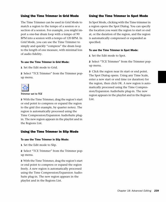
Using the Time Trimmer in Grid Mode
The Time Trimmer can be used in Grid Mode to match a region to the tempo of a session or a section of a session. For example, you might im-port a one-bar drum loop with a tempo of 90 BPM into a session with a tempo of 120 BPM. In Grid Mode, you can use the Time Trimmer to simply and quickly “compress” the drum loop to the length of one measure, with minimal loss of audio fidelity.
To use the Time Trimmer in Grid Mode:
1 Set the Edit mode to Grid.
2 Select “TCE Trimmer” from the Trimmer pop-up menu.
3 With the Time Trimmer, drag the region’s start or end point to compress or expand the region to the grid (for example, by quarter notes). The region is automatically processed using the Time Compression/Expansion AudioSuite plug-in. The new region appears in the playlist and in the Regions List.
Using the Time Trimmer in Slip Mode
To use the Time Trimmer in Slip Mode:
1 Set the Edit mode to Slip.
2 Select “TCE Trimmer” from the Trimmer pop-up menu.
3 With the Time Trimmer, drag the region’s start or end point to compress or expand the region freely. A new region is automatically processed using the Time Compression/Expansion Audio-Suite plug-in. The new region appears in the playlist and in the Regions List.
Trimmer set to TCE
Using the Time Trimmer in Spot Mode
In Spot Mode, clicking with the Time trimmer in a region opens the Spot Dialog. You can specify the location you want the region to start or end at, or the duration of the region, and the region is automatically compressed or expanded as specified.
To use the Time Trimmer in Spot Mode:
1 Set the Edit mode to Spot.
2 Select “TCE Trimmer” from the Trimmer pop-up menu.
3 Click the region near its start or end point. The Spot Dialog opens. Using any Time Scale, enter a new start or end time (or duration) for the region, then click OK. A new region is auto-matically processed using the Time Compres-sion/Expansion AudioSuite plug-in. The new region appears in the playlist and in the Regions List.
Chapter 18: Advanced Editing 239

240
Pro Tools Reference Guide
Chapter 19: Fades and Crossfades
Using CrossfadesYou can quickly and easily crossfade between two adjacent audio regions. Crossfading is the process of fading two regions of audio to pre-vent pops, clicks, or sudden changes in sound. Crossfades have many applications, from smoothing transitions between regions to creat-ing special audio effects. The crossfade duration, position, and shape are all user-definable.
Crossfades are computed and written to disk. Crossfades that are written to disk are stored in a folder named “Fade Files” within the session folder. When you play back your track, Pro Tools reads and plays back the crossfade file from disk.
Pro Tools 24 and MIX systems include an Auto Fade feature that provides real-time fades without processing them to disk. See “Using AutoFades” on page 250.
About Crossfades and Curves
To create a crossfade between two regions, use the Selector to select across the end point of the first region and the start point of the second. The length of the selection determines the length of the crossfade. Though fades may ap-pear to be discrete regions, they cannot actually be separated from the regions in which they were created. You can, however, create fade-ins and fade-outs for individual regions (see “Creat-ing Fades at the Beginnings and Ends of Re-gions” on page 249).
You can use the Fades dialog to select, view, and manipulate the curves used to perform the crossfade. Different volume curves can be as-signed to the fade-out and fade-in portions of crossfades. The Fades dialog can also render a preview of the fade.
The following examples illustrate common crossfade types, and explain how the type of se-lection you make determines the character of the crossfade.
NOTE: Since crossfades are created by fading be-tween overlapping audio material, a crossfade can-not be performed on regions that do not contain au-dio material beyond their region boundaries.
Chapter 19: Fades and Crossfades 241
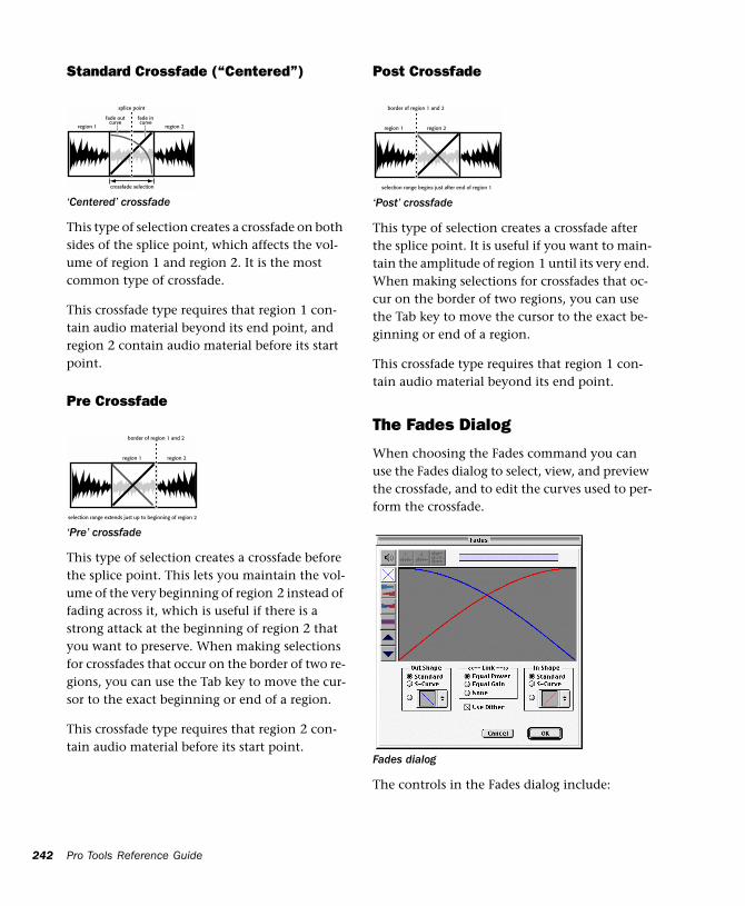
242
Standard Crossfade (“Centered”)
This type of selection creates a crossfade on both sides of the splice point, which affects the vol-ume of region 1 and region 2. It is the most common type of crossfade.
This crossfade type requires that region 1 con-tain audio material beyond its end point, and region 2 contain audio material before its start point.
Pre Crossfade
This type of selection creates a crossfade before the splice point. This lets you maintain the vol-ume of the very beginning of region 2 instead of fading across it, which is useful if there is a strong attack at the beginning of region 2 that you want to preserve. When making selections for crossfades that occur on the border of two re-gions, you can use the Tab key to move the cur-sor to the exact beginning or end of a region.
This crossfade type requires that region 2 con-tain audio material before its start point.
‘Centered’ crossfade
‘Pre’ crossfade
region 1
fade outcurve
fade incurve
region 2
splice point
crossfade selection
region 1 region 2
border of region 1 and 2
selection range extends just up to beginning of region 2
Pro Tools Reference Guide
Post Crossfade
This type of selection creates a crossfade after the splice point. It is useful if you want to main-tain the amplitude of region 1 until its very end. When making selections for crossfades that oc-cur on the border of two regions, you can use the Tab key to move the cursor to the exact be-ginning or end of a region.
This crossfade type requires that region 1 con-tain audio material beyond its end point.
The Fades Dialog
When choosing the Fades command you can use the Fades dialog to select, view, and preview the crossfade, and to edit the curves used to per-form the crossfade.
The controls in the Fades dialog include:
‘Post’ crossfade
Fades dialog
region 1 region 2
border of region 1 and 2
selection range begins just after end of region 1
Audition
Click this button to audition your crossfade. Pro Tools plays the audio in one of two ways, depending on your system:
◆ Pro Tools 24 MIX and Pro Tools 24 systems al-low crossfade auditioning directly from your au-dio interface outputs.
◆ All other Pro Tools systems use Apple’s Sound Manager to audition crossfades. Use the Digide-sign Sound Drivers (automatically installed with Pro Tools) to audition via your audio interface outputs. Use the Macintosh Sound Control Panel to set the Output choice to Digidesign Sound Drivers. (If you do not use the Sound Drivers, you will hear crossfades through the Macintosh’s audio output.)
View First Track
If you are fading between more than one track, this button allows you to view and preview the audio of the first pair of adjacent tracks.
View Second Track
If you are fading between more than one track this button allows you to view and preview the audio of the second pair of adjacent tracks.
View Both Tracks
Click this button to display the waveforms of the first two adjacent tracks in a multitrack fade.
Fade Curves Only
Click this button to display the specified fade curves without showing the actual audio wave-forms. This is the default view when you open the Fades dialog.
Fade Curves and Separate Waveforms
Click this button to display the specified fade curves along with separate views of the fade-in and fade-out waveforms.
Fade Curves and Superimposed Waveforms
Click this button to display the specified fade curves along with superimposed views of the fade-in and fade-out waveforms.
Fade Curves and Summed Waveform
Click this button to display the specified fade curves along with a single waveform represent-ing the summation of the crossfaded audio.
Zoom In
Click this button to scale the view of the wave-form’s amplitude upwards. Command-click (Macintosh) or Control-click (Windows) for the default view scale.
Chapter 19: Fades and Crossfades 243
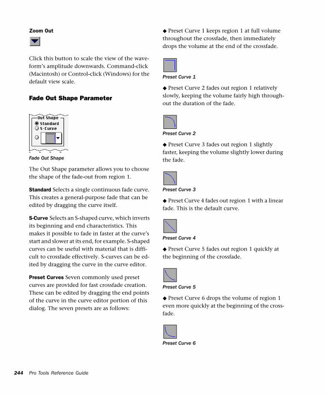
244
Zoom Out
Click this button to scale the view of the wave-form’s amplitude downwards. Command-click (Macintosh) or Control-click (Windows) for the default view scale.
Fade Out Shape Parameter
The Out Shape parameter allows you to choose the shape of the fade-out from region 1.
Standard Selects a single continuous fade curve. This creates a general-purpose fade that can be edited by dragging the curve itself.
S-Curve Selects an S-shaped curve, which inverts its beginning and end characteristics. This makes it possible to fade in faster at the curve’s start and slower at its end, for example. S-shaped curves can be useful with material that is diffi-cult to crossfade effectively. S-curves can be ed-ited by dragging the curve in the curve editor.
Preset Curves Seven commonly used preset curves are provided for fast crossfade creation. These can be edited by dragging the end points of the curve in the curve editor portion of this dialog. The seven presets are as follows:
Fade Out Shape
Pro Tools Reference Guide
◆ Preset Curve 1 keeps region 1 at full volume throughout the crossfade, then immediately drops the volume at the end of the crossfade.
◆ Preset Curve 2 fades out region 1 relatively slowly, keeping the volume fairly high through-out the duration of the fade.
◆ Preset Curve 3 fades out region 1 slightly faster, keeping the volume slightly lower during the fade.
◆ Preset Curve 4 fades out region 1 with a linear fade. This is the default curve.
◆ Preset Curve 5 fades out region 1 quickly at the beginning of the crossfade.
◆ Preset Curve 6 drops the volume of region 1 even more quickly at the beginning of the cross-fade.
Preset Curve 1
Preset Curve 2
Preset Curve 3
Preset Curve 4
Preset Curve 5
Preset Curve 6
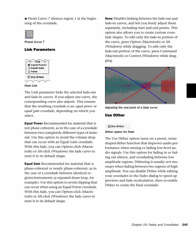
◆ Preset Curve 7 silences region 1 at the begin-ning of the crossfade.
Link Parameters
The Link parameter links the selected fade-out and fade-in curves. If you adjust one curve, the corresponding curve also adjusts. This ensures that the resulting crossfade is an equal power or equal gain crossfade, depending on which you select.
Equal Power Recommended for material that is not phase coherent, as in the case of a crossfade between two completely different types of mate-rial. Use this option to avoid the volume drop that can occur with an Equal Gain crossfade. With this fade, you can Option-click (Macin-tosh) or Alt-click (Windows) the fade curve to reset it to its default shape.
Equal Gain Recommended for material that is phase-coherent or nearly phase-coherent, as in the case of a crossfade between identical re-gions/instruments (a repeated drum loop, for example). Use this option to avoid clipping that can occur when using an Equal Power crossfade. With this fade, you can Option-click (Macin-tosh) or Alt-click (Windows) the fade curve to reset it to its default shape.
Preset Curve 7
Fade Link
None Disables linking between the fade-out and fade-in curves, and lets you freely adjust them separately, including start and end points. This option also allows you to create custom cross-fade shapes. To edit only the fade-in portion of the curve, press Option (Macintosh) or Alt (Windows) while dragging. To edit only the fade-out portion of the curve, press Command (Macintosh) or Control (Windows) while drag-ging.
Use Dither
The Use Dither option turns on a preset, noise-shaped dither function that improves audio per-formance when mixing or fading low-level au-dio signals. Use this option for fading in or fad-ing out silence, and crossfading between low amplitude regions. Dithering is usually not nec-essary when fading between two regions of high amplitude. You can disable Dither while editing your crossfades in the Fades dialog to speed up previews and fade recalculation, then re-enable Dither to create the final crossfade.
Adjusting the end point of a fade curve
Dither option for Fade
Chapter 19: Fades and Crossfades 245
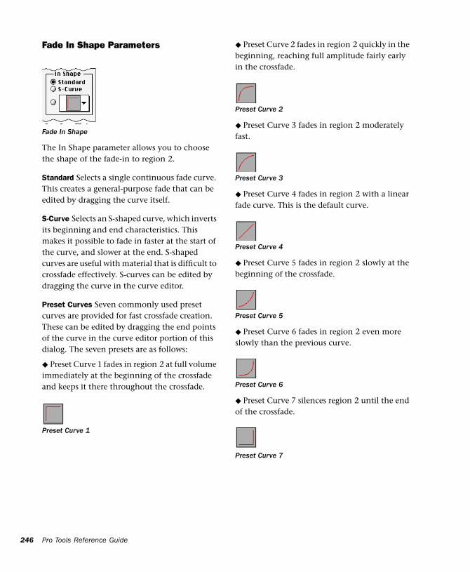
246
Fade In Shape Parameters
The In Shape parameter allows you to choose the shape of the fade-in to region 2.
Standard Selects a single continuous fade curve. This creates a general-purpose fade that can be edited by dragging the curve itself.
S-Curve Selects an S-shaped curve, which inverts its beginning and end characteristics. This makes it possible to fade in faster at the start of the curve, and slower at the end. S-shaped curves are useful with material that is difficult to crossfade effectively. S-curves can be edited by dragging the curve in the curve editor.
Preset Curves Seven commonly used preset curves are provided for fast crossfade creation. These can be edited by dragging the end points of the curve in the curve editor portion of this dialog. The seven presets are as follows:
◆ Preset Curve 1 fades in region 2 at full volume immediately at the beginning of the crossfade and keeps it there throughout the crossfade.
Fade In Shape
Preset Curve 1
Pro Tools Reference Guide
◆ Preset Curve 2 fades in region 2 quickly in the beginning, reaching full amplitude fairly early in the crossfade.
◆ Preset Curve 3 fades in region 2 moderately fast.
◆ Preset Curve 4 fades in region 2 with a linear fade curve. This is the default curve.
◆ Preset Curve 5 fades in region 2 slowly at the beginning of the crossfade.
◆ Preset Curve 6 fades in region 2 even more slowly than the previous curve.
◆ Preset Curve 7 silences region 2 until the end of the crossfade.
Preset Curve 2
Preset Curve 3
Preset Curve 4
Preset Curve 5
Preset Curve 6
Preset Curve 7
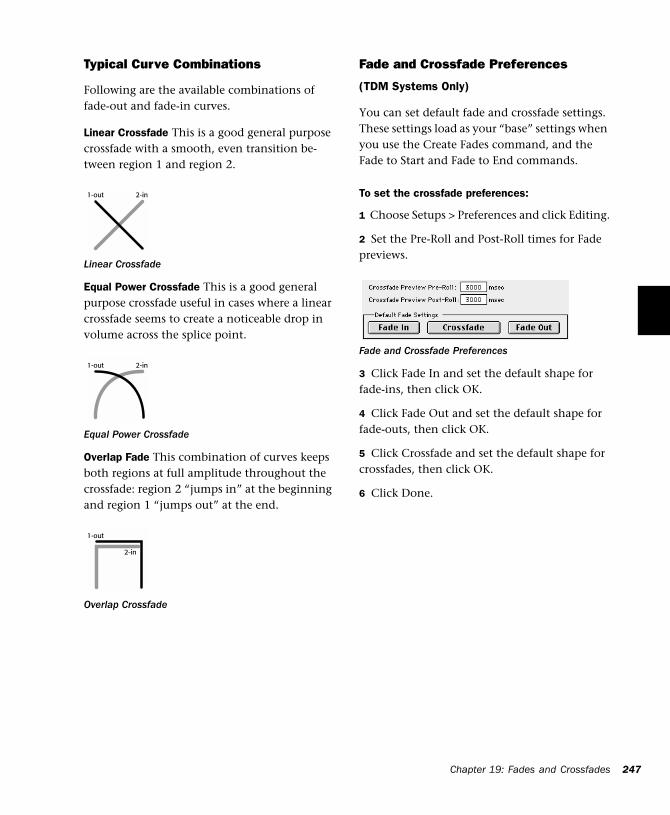
Typical Curve Combinations
Following are the available combinations of fade-out and fade-in curves.
Linear Crossfade This is a good general purpose crossfade with a smooth, even transition be-tween region 1 and region 2.
Equal Power Crossfade This is a good general purpose crossfade useful in cases where a linear crossfade seems to create a noticeable drop in volume across the splice point.
Overlap Fade This combination of curves keeps both regions at full amplitude throughout the crossfade: region 2 “jumps in” at the beginning and region 1 “jumps out” at the end.
Linear Crossfade
Equal Power Crossfade
Overlap Crossfade
1-out 2-in
1-out 2-in
1-out
2-in
Fade and Crossfade Preferences
(TDM Systems Only)
You can set default fade and crossfade settings. These settings load as your “base” settings when you use the Create Fades command, and the Fade to Start and Fade to End commands.
To set the crossfade preferences:
1 Choose Setups > Preferences and click Editing.
2 Set the Pre-Roll and Post-Roll times for Fade previews.
3 Click Fade In and set the default shape for fade-ins, then click OK.
4 Click Fade Out and set the default shape for fade-outs, then click OK.
5 Click Crossfade and set the default shape for crossfades, then click OK.
6 Click Done.
Fade and Crossfade Preferences
Chapter 19: Fades and Crossfades 247
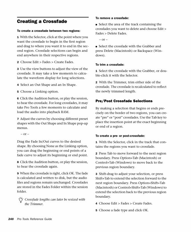
248
Creating a Crossfade
To create a crossfade between two regions:
1 With the Selector, click at the point where you want the crossfade to begin in the first region and drag to where you want it to end in the sec-ond region. Crossfade selections can begin and end anywhere in their respective regions.
2 Choose Edit > Fades > Create Fades.
3 Use the view buttons to adjust the view of the crossfade. It may take a few moments to calcu-late the waveform display for long selections.
4 Select an Out Shape and an In Shape.
5 Choose a Linking option.
6 Click the Audition button, or play the session, to hear the crossfade. For long crossfades, it may take Pro Tools a few moments to calculate and load the audio into playback RAM.
7 Adjust the curves by choosing different preset shapes with the Out Shape and In Shape pop-up menus.
– or –
Drag the Fade In/Out curves to the desired shape. By choosing None as the Linking option, you can drag the beginning or end points of a fade curve to adjust its beginning or end point.
8 Click the Audition button, or play the session, to hear the crossfade again.
9 When the crossfade is right, click OK. The fade is calculated and written to disk, but the audio files and regions remain unchanged. Crossfades are stored in the Fades Folder within the session folder.
Crossfade lengths can later be resized with the Trimmer.
Pro Tools Reference Guide
To remove a crossfade:
■ Select the area of the track containing the crossfades you want to delete and choose Edit > Fades > Delete Fades.
– or –
■ Select the crossfade with the Grabber and press Delete (Macintosh) or Backspace (Win-dows).
To trim a crossfade:
1 Select the crossfade with the Grabber, or dou-ble-click it with the Selector.
2 With the Trimmer, trim either side of the crossfade. The crossfade is recalculated to reflect the newly trimmed length.
Pre/Post Crossfade Selections
By making a selection that begins or ends pre-cisely on the border of two regions, you can cre-ate “pre” or “post” crossfades. Use the Tab key to place the insertion point at the exact beginning or end of a region.
To create a pre- or post-crossfade:
1 With the Selector, click in the track that con-tains the regions you want to crossfade.
2 Press Tab to move forward to the next region boundary. Press Option+Tab (Macintosh) or Control+Tab (Windows) to move back to the previous region boundary.
3 Shift-drag to adjust your selection, or press Shift+Tab to extend the selection forward to the next region boundary. Press Option+Shift+Tab (Macintosh) or Control+Shift+Tab (Windows) to extend the selection back to the previous region boundary.
4 Choose Edit > Fades > Create Fades.
5 Choose a fade type and click OK.
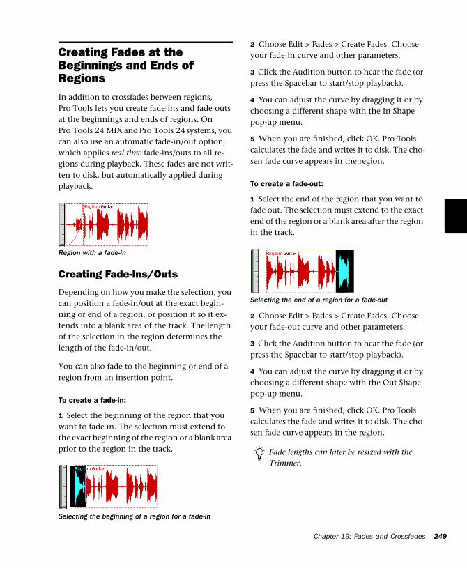
Creating Fades at the Beginnings and Ends of RegionsIn addition to crossfades between regions, Pro Tools lets you create fade-ins and fade-outs at the beginnings and ends of regions. On Pro Tools 24 MIX and Pro Tools 24 systems, you can also use an automatic fade-in/out option, which applies real time fade-ins/outs to all re-gions during playback. These fades are not writ-ten to disk, but automatically applied during playback.
Creating Fade-Ins/Outs
Depending on how you make the selection, you can position a fade-in/out at the exact begin-ning or end of a region, or position it so it ex-tends into a blank area of the track. The length of the selection in the region determines the length of the fade-in/out.
You can also fade to the beginning or end of a region from an insertion point.
To create a fade-in:
1 Select the beginning of the region that you want to fade in. The selection must extend to the exact beginning of the region or a blank area prior to the region in the track.
Region with a fade-in
Selecting the beginning of a region for a fade-in
2 Choose Edit > Fades > Create Fades. Choose your fade-in curve and other parameters.
3 Click the Audition button to hear the fade (or press the Spacebar to start/stop playback).
4 You can adjust the curve by dragging it or by choosing a different shape with the In Shape pop-up menu.
5 When you are finished, click OK. Pro Tools calculates the fade and writes it to disk. The cho-sen fade curve appears in the region.
To create a fade-out:
1 Select the end of the region that you want to fade out. The selection must extend to the exact end of the region or a blank area after the region in the track.
2 Choose Edit > Fades > Create Fades. Choose your fade-out curve and other parameters.
3 Click the Audition button to hear the fade (or press the Spacebar to start/stop playback).
4 You can adjust the curve by dragging it or by choosing a different shape with the Out Shape pop-up menu.
5 When you are finished, click OK. Pro Tools calculates the fade and writes it to disk. The cho-sen fade curve appears in the region.
Selecting the end of a region for a fade-out
Fade lengths can later be resized with the Trimmer.
Chapter 19: Fades and Crossfades 249
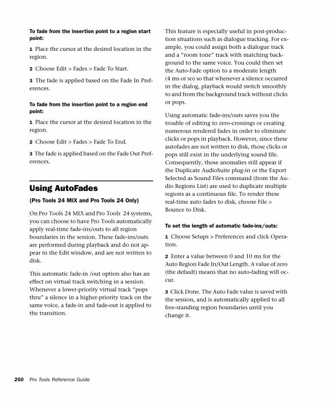
250
To fade from the insertion point to a region start point:
1 Place the cursor at the desired location in the region.
2 Choose Edit > Fades > Fade To Start.
3 The fade is applied based on the Fade In Pref-erences.
To fade from the insertion point to a region end point:
1 Place the cursor at the desired location in the region.
2 Choose Edit > Fades > Fade To End.
3 The fade is applied based on the Fade Out Pref-erences.
Using AutoFades{Pro Tools 24 MIX and Pro Tools 24 Only)
On Pro Tools 24 MIX and Pro Tools 24 systems, you can choose to have Pro Tools automatically apply real-time fade-ins/outs to all region boundaries in the session. These fade-ins/outs are performed during playback and do not ap-pear in the Edit window, and are not written to disk.
This automatic fade-in /out option also has an effect on virtual track switching in a session. Whenever a lower-priority virtual track “pops thru” a silence in a higher-priority track on the same voice, a fade-in and fade-out is applied to the transition.
Pro Tools Reference Guide
This feature is especially useful in post-produc-tion situations such as dialogue tracking. For ex-ample, you could assign both a dialogue track and a “room tone” track with matching back-ground to the same voice. You could then set the Auto-Fade option to a moderate length (4 ms or so) so that whenever a silence occurred in the dialog, playback would switch smoothly to and from the background track without clicks or pops.
Using automatic fade-ins/outs saves you the trouble of editing to zero-crossings or creating numerous rendered fades in order to eliminate clicks or pops in playback. However, since these autofades are not written to disk, those clicks or pops still exist in the underlying sound file. Consequently, those anomalies still appear if the Duplicate AudioSuite plug-in or the Export Selected as Sound Files command (from the Au-dio Regions List) are used to duplicate multiple regions as a continuous file. To render these real-time auto fades to disk, choose File > Bounce to Disk.
To set the length of automatic fade-ins/outs:
1 Choose Setups > Preferences and click Opera-tion.
2 Enter a value between 0 and 10 ms for the Auto Region Fade In/Out Length. A value of zero (the default) means that no auto-fading will oc-cur.
3 Click Done. The Auto Fade value is saved with the session, and is automatically applied to all free-standing region boundaries until you change it.
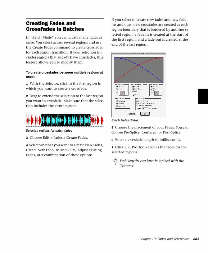
Creating Fades and Crossfades in BatchesIn “Batch Mode” you can create many fades at once. You select across several regions and use the Create Fades command to create crossfades for each region transition. If your selection in-cludes regions that already have crossfades, this feature allows you to modify them.
To create crossfades between multiple regions at once:
1 With the Selector, click in the first region in which you want to create a crossfade.
2 Drag to extend the selection to the last region you want to crossfade. Make sure that the selec-tion includes the entire region.
3 Choose Edit > Fades > Create Fades.
4 Select whether you want to Create New Fades, Create New Fade-Ins and Outs, Adjust existing Fades, or a combination of these options.
Selected regions for batch fades
If you select to create new fades and new fade-ins and outs, new crossfades are created at each region boundary that is bordered by another se-lected region, a fade-in is created at the start of the first region, and a fade-out is created at the end of the last region.
5 Choose the placement of your Fades. You can choose Pre-Splice, Centered, or Post-Splice.
6 Enter a crossfade length in milliseconds.
7 Click OK. Pro Tools creates the fades for the selected regions.
Batch Fades dialog
Fade lengths can later be resized with the Trimmer.
Chapter 19: Fades and Crossfades 251

252
Pro Tools Reference Guide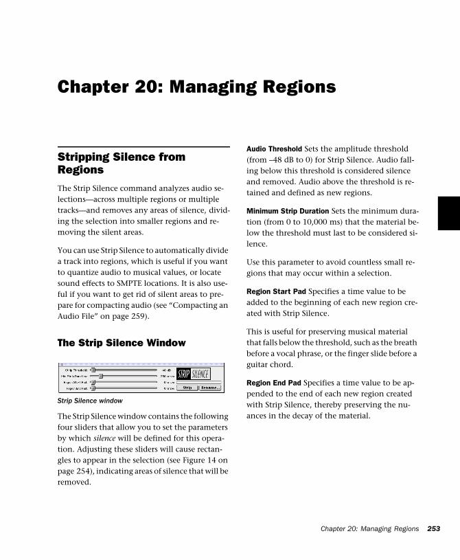
Chapter 20: Managing Regions
Stripping Silence from RegionsThe Strip Silence command analyzes audio se-lections—across multiple regions or multiple tracks—and removes any areas of silence, divid-ing the selection into smaller regions and re-moving the silent areas.
You can use Strip Silence to automatically divide a track into regions, which is useful if you want to quantize audio to musical values, or locate sound effects to SMPTE locations. It is also use-ful if you want to get rid of silent areas to pre-pare for compacting audio (see “Compacting an Audio File” on page 259).
The Strip Silence Window
The Strip Silence window contains the following four sliders that allow you to set the parameters by which silence will be defined for this opera-tion. Adjusting these sliders will cause rectan-gles to appear in the selection (see Figure 14 on page 254), indicating areas of silence that will be removed.
Strip Silence window
Audio Threshold Sets the amplitude threshold (from –48 dB to 0) for Strip Silence. Audio fall-ing below this threshold is considered silence and removed. Audio above the threshold is re-tained and defined as new regions.
Minimum Strip Duration Sets the minimum dura-tion (from 0 to 10,000 ms) that the material be-low the threshold must last to be considered si-lence.
Use this parameter to avoid countless small re-gions that may occur within a selection.
Region Start Pad Specifies a time value to be added to the beginning of each new region cre-ated with Strip Silence.
This is useful for preserving musical material that falls below the threshold, such as the breath before a vocal phrase, or the finger slide before a guitar chord.
Region End Pad Specifies a time value to be ap-pended to the end of each new region created with Strip Silence, thereby preserving the nu-ances in the decay of the material.
Chapter 20: Managing Regions 253
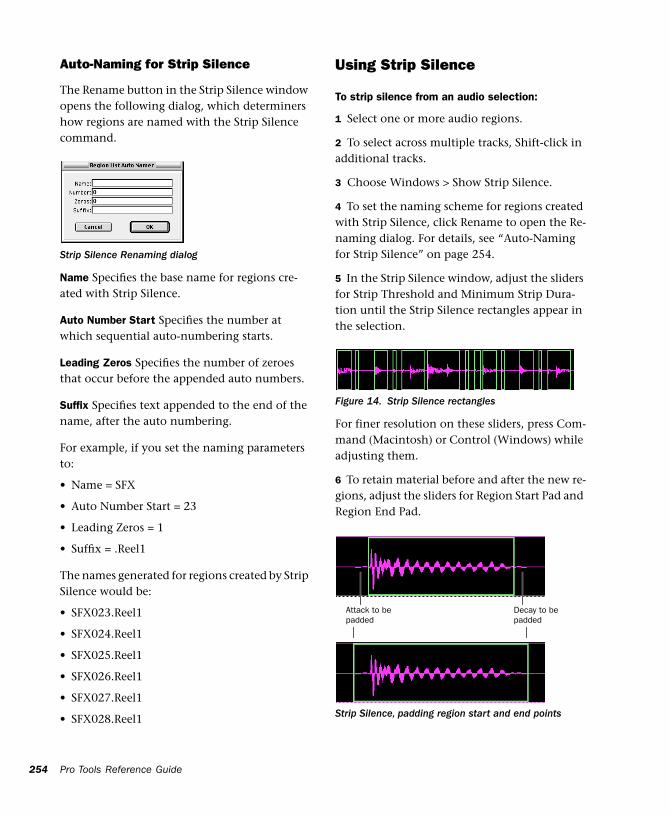
254
Auto-Naming for Strip Silence
The Rename button in the Strip Silence window opens the following dialog, which determiners how regions are named with the Strip Silence command.
Name Specifies the base name for regions cre-ated with Strip Silence.
Auto Number Start Specifies the number at which sequential auto-numbering starts.
Leading Zeros Specifies the number of zeroes that occur before the appended auto numbers.
Suffix Specifies text appended to the end of the name, after the auto numbering.
For example, if you set the naming parameters to:
• Name = SFX
• Auto Number Start = 23
• Leading Zeros = 1
• Suffix = .Reel1
The names generated for regions created by Strip Silence would be:
• SFX023.Reel1
• SFX024.Reel1
• SFX025.Reel1
• SFX026.Reel1
• SFX027.Reel1
• SFX028.Reel1
Strip Silence Renaming dialog
Pro Tools Reference Guide
Using Strip Silence
To strip silence from an audio selection:
1 Select one or more audio regions.
2 To select across multiple tracks, Shift-click in additional tracks.
3 Choose Windows > Show Strip Silence.
4 To set the naming scheme for regions created with Strip Silence, click Rename to open the Re-naming dialog. For details, see “Auto-Naming for Strip Silence” on page 254.
5 In the Strip Silence window, adjust the sliders for Strip Threshold and Minimum Strip Dura-tion until the Strip Silence rectangles appear in the selection.
For finer resolution on these sliders, press Com-mand (Macintosh) or Control (Windows) while adjusting them.
6 To retain material before and after the new re-gions, adjust the sliders for Region Start Pad and Region End Pad.
Figure 14. Strip Silence rectangles
Strip Silence, padding region start and end points
Attack to be padded
Decay to be padded
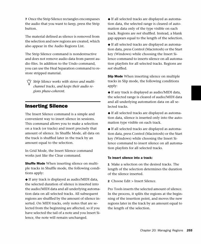
7 Once the Strip Silence rectangles encompasses the audio that you want to keep, press the Strip button.
The material defined as silence is removed from the selection and new regions are created, which also appear in the Audio Regions List.
The Strip Silence command is nondestructive and does not remove audio data from parent au-dio files. In addition to the Undo command, you can use the Heal Separation command to re-store stripped material.
Inserting SilenceThe Insert Silence command is a simple and convenient way to insert silence in sessions. This command allows you to make a selection on a track (or tracks) and insert precisely that amount of silence. In Shuffle Mode, all data on the track is shuffled later in the track by an amount equal to the selection.
In Grid Mode, the Insert Silence command works just like the Clear command.
Shuffle Mode When inserting silence on multi-ple tracks in Shuffle mode, the following condi-tions apply:
◆ If any track is displayed as audio/MIDI data, the selected duration of silence is inserted into the audio/MIDI data and all underlying automa-tion data on all selected tracks. All subsequent regions are shuffled by the amount of silence in-serted. On MIDI tracks, only notes that are se-lected from the beginning are affected, so if you have selected the tail of a note and you Insert Si-lence, the note will remain unchanged.
Strip Silence works with stereo and multi-channel tracks, and keeps their audio re-gions phase-coherent.
◆ If all selected tracks are displayed as automa-tion data, the selected range is cleared of auto-mation data only of the type visible on each track. Regions are not shuffled. Instead, a blank gap appears equal to the length of the selection.
◆ If all selected tracks are displayed as automa-tion data, press Control (Macintosh) or the Start key (Windows) while choosing the Insert Si-lence command to inserts silence on all automa-tion playlists for all selected tracks. Regions are not shuffled.
Slip Mode When inserting silence on multiple tracks in Slip mode, the following conditions apply:
◆ If any track is displayed as audio/MIDI data, the selected range is cleared of audio/MIDI data and all underlying automation data on all se-lected tracks.
◆ If all selected tracks are displayed as automa-tion data, silence is inserted only into the auto-mation type visible on each track.
◆ If all selected tracks are displayed as automa-tion data, press Control (Macintosh) or the Start key (Windows) while choosing the Insert Si-lence command to insert silence on all automa-tion playlists for all selected tracks.
To insert silence into a track:
1 Make a selection on the desired tracks. The length of the selection determines the duration of the silence inserted.
2 Choose Edit > Insert Silence.
Pro Tools inserts the selected amount of silence. In the process, it splits the regions at the begin-ning of the insertion point, and moves the new regions later in the track by an amount equal to the length of the selection.
Chapter 20: Managing Regions 255
256
Consolidate Selection CommandDuring the course of normal edit operations, a track may eventually contain many regions. However, once a track or track range (such as a verse or chorus) reaches a satisfactory state, you may want to consolidate its regions into a single region—thus making the material much more easy to work with.
When consolidating an audio track, a new audio file is written that encompasses the selection range, including any blank space.
To consolidate regions within a track:
1 Using the Grabber or Selector, select the re-gions you want to consolidate.
– or –
To select all regions in a track, triple-click in its playlist with the Selector.
2 Choose Edit > Consolidate.
A new, single region is created that replaces the previously selected regions, including any blank space. If working with an audio track, a new au-dio file is written (with the Audio Suite Dupli-cate plug-in).
When consolidating audio regions with the Consolidate Selection command, if the selec-tion contains muted regions, the muted regions are treated as silence. Whether or not a track is muted, or contains Mute automation, does not affect the Consolidate Selection command.
Pro Tools Reference Guide
Managing RegionsA typical session can become quite busy with many tracks and dozens of regions. There are a number of things you can do, however, to keep track of and manage a session’s regions, which include:
• Renaming existing regions
• Specifying how auto-created regions are named
• Hiding auto-created regions
• Removing unused regions
Renaming Regions
In the course of a session you can rename re-gions to give them more descriptive names, or merely to shorten or simplify an existing name. When renaming a region that was auto-created from an edit, the region becomes a user-defined region and is displayed in the Regions List when auto-created regions are hidden.
Perhaps the easiest way to rename a region, if it resides in a track, is to double-click it with the Grabber. However, if the region does not yet re-side in a track, or if you want to rename several regions, use the Rename Selected command.
To rename one or more regions:
1 If you will be renaming an auto-created re-gion, make sure to select Display > Auto-Created Regions.
2 Select one or more region to be renamed in ei-ther the Audio or MIDI Regions List.
If the Editing Preference for “Regions List Selection Follows Track Selection” is en-abled, you can highlight a region in the Re-gions List by selecting it in a track.
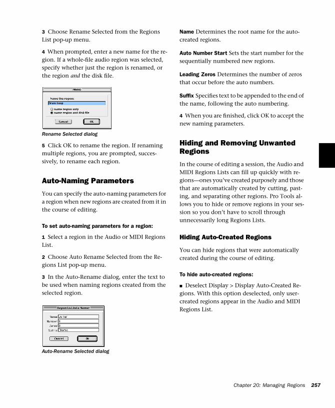
3 Choose Rename Selected from the Regions List pop-up menu.
4 When prompted, enter a new name for the re-gion. If a whole-file audio region was selected, specify whether just the region is renamed, or the region and the disk file.
5 Click OK to rename the region. If renaming multiple regions, you are prompted, succes-sively, to rename each region.
Auto-Naming Parameters
You can specify the auto-naming parameters for a region when new regions are created from it in the course of editing.
To set auto-naming parameters for a region:
1 Select a region in the Audio or MIDI Regions List.
2 Choose Auto Rename Selected from the Re-gions List pop-up menu.
3 In the Auto-Rename dialog, enter the text to be used when naming regions created from the selected region.
Rename Selected dialog
Auto-Rename Selected dialog
Name Determines the root name for the auto-created regions.
Auto Number Start Sets the start number for the sequentially numbered new regions.
Leading Zeros Determines the number of zeros that occur before the auto numbers.
Suffix Specifies text to be appended to the end of the name, following the auto numbering.
4 When you are finished, click OK to accept the new naming parameters.
Hiding and Removing Unwanted Regions
In the course of editing a session, the Audio and MIDI Regions Lists can fill up quickly with re-gions—ones you’ve created purposely and those that are automatically created by cutting, past-ing, and separating other regions. Pro Tools al-lows you to hide or remove regions in your ses-sion so you don’t have to scroll through unnecessarily long Regions Lists.
Hiding Auto-Created Regions
You can hide regions that were automatically created during the course of editing.
To hide auto-created regions:
■ Deselect Display > Display Auto-Created Re-gions. With this option deselected, only user-created regions appear in the Audio and MIDI Regions List.
Chapter 20: Managing Regions 257
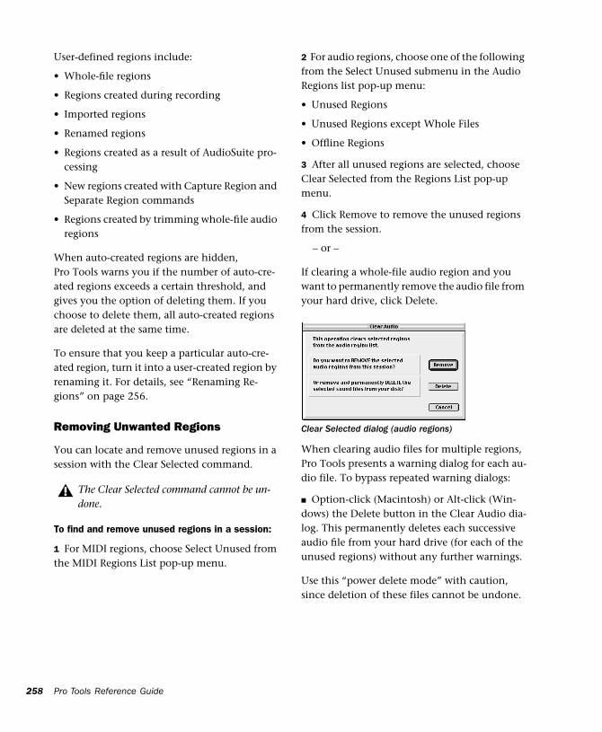
258
User-defined regions include:
• Whole-file regions
• Regions created during recording
• Imported regions
• Renamed regions
• Regions created as a result of AudioSuite pro-cessing
• New regions created with Capture Region and Separate Region commands
• Regions created by trimming whole-file audio regions
When auto-created regions are hidden, Pro Tools warns you if the number of auto-cre-ated regions exceeds a certain threshold, and gives you the option of deleting them. If you choose to delete them, all auto-created regions are deleted at the same time.
To ensure that you keep a particular auto-cre-ated region, turn it into a user-created region by renaming it. For details, see “Renaming Re-gions” on page 256.
Removing Unwanted Regions
You can locate and remove unused regions in a session with the Clear Selected command.
To find and remove unused regions in a session:
1 For MIDI regions, choose Select Unused from the MIDI Regions List pop-up menu.
The Clear Selected command cannot be un-done.
Pro Tools Reference Guide
2 For audio regions, choose one of the following from the Select Unused submenu in the Audio Regions list pop-up menu:
• Unused Regions
• Unused Regions except Whole Files
• Offline Regions
3 After all unused regions are selected, choose Clear Selected from the Regions List pop-up menu.
4 Click Remove to remove the unused regions from the session.
– or –
If clearing a whole-file audio region and you want to permanently remove the audio file from your hard drive, click Delete.
When clearing audio files for multiple regions, Pro Tools presents a warning dialog for each au-dio file. To bypass repeated warning dialogs:
■ Option-click (Macintosh) or Alt-click (Win-dows) the Delete button in the Clear Audio dia-log. This permanently deletes each successive audio file from your hard drive (for each of the unused regions) without any further warnings.
Use this “power delete mode” with caution, since deletion of these files cannot be undone.
Clear Selected dialog (audio regions)
Compacting an Audio FileThe Compact Selected command deletes unused portions of audio files to conserve disk space, and to prepare for cleaner hard drive back-ups.
The Compact Selected command deletes audio if there are no regions referencing the data. For this reason you should delete any unused re-gions before compacting.
Because it permanently deletes audio data, the Compact Selected command should be used only after you have completely finished your editing and are sure that you have no further use for the unused audio data.
The Compact Selected command can pad the re-gions of the compacted file by a user-selectable amount. You may want to do this because Pro Tools requires extra audio data before and after audio regions to create crossfades. So, if your regions have crossfades, or if you want to pad the regions for the sake of any future trim-ming, you should enter an appropriate amount of padding (in milliseconds) to allow for this.
The Compact Selected command is destruc-tive and cannot be undone. It permanently alters the original audio files. There is no way to recover data deleted with this com-mand.
To compact an audio file:
1 Choose Select Unused >Regions from the Au-dio Regions List pop-up menu. All regions that have not been placed in a track in the current session are highlighted in the Audio Regions List.
2 To remove all of these unused audio regions, choose Clear Selected from the Audio Regions List pop-up menu. When the dialog appears, choose Remove.
3 In the Audio Regions List, select the region or regions you want to compact.
4 Choose Compact Selected from the Audio Re-gions List menu.
5 Enter the amount of padding in milliseconds that you want to leave around each region in the file.
6 Click Compact to compact the file or Cancel to cancel the command.
Once the Compact operation has been com-pleted, the session is automatically saved.
Chapter 20: Managing Regions 259

260
Pro Tools Reference Guide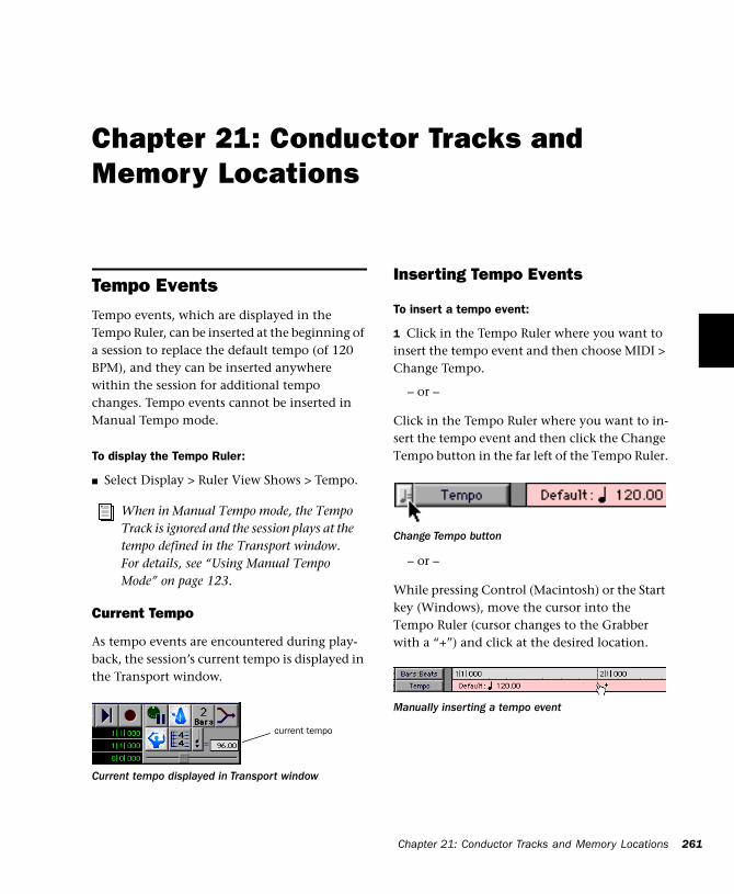
Chapter 21: Conductor Tracks and Memory Locations
Tempo EventsTempo events, which are displayed in the Tempo Ruler, can be inserted at the beginning of a session to replace the default tempo (of 120 BPM), and they can be inserted anywhere within the session for additional tempo changes. Tempo events cannot be inserted in Manual Tempo mode.
To display the Tempo Ruler:
■ Select Display > Ruler View Shows > Tempo.
Current Tempo
As tempo events are encountered during play-back, the session’s current tempo is displayed in the Transport window.
When in Manual Tempo mode, the Tempo Track is ignored and the session plays at the tempo defined in the Transport window. For details, see “Using Manual Tempo Mode” on page 123.
Current tempo displayed in Transport window
current tempo
Inserting Tempo Events
To insert a tempo event:
1 Click in the Tempo Ruler where you want to insert the tempo event and then choose MIDI > Change Tempo.
– or –
Click in the Tempo Ruler where you want to in-sert the tempo event and then click the Change Tempo button in the far left of the Tempo Ruler.
– or –
While pressing Control (Macintosh) or the Start key (Windows), move the cursor into the Tempo Ruler (cursor changes to the Grabber with a “+”) and click at the desired location.
Change Tempo button
Manually inserting a tempo event
Chapter 21: Conductor Tracks and Memory Locations 261
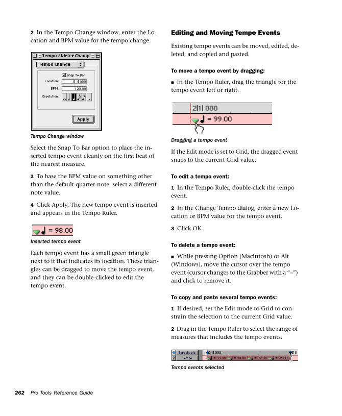
262
2 In the Tempo Change window, enter the Lo-cation and BPM value for the tempo change.
Select the Snap To Bar option to place the in-serted tempo event cleanly on the first beat of the nearest measure.
3 To base the BPM value on something other than the default quarter-note, select a different note value.
4 Click Apply. The new tempo event is inserted and appears in the Tempo Ruler.
Each tempo event has a small green triangle next to it that indicates its location. These trian-gles can be dragged to move the tempo event, and they can be double-clicked to edit the tempo event.
Tempo Change window
Inserted tempo event
Pro Tools Reference Guide
Editing and Moving Tempo Events
Existing tempo events can be moved, edited, de-leted, and copied and pasted.
To move a tempo event by dragging:
■ In the Tempo Ruler, drag the triangle for the tempo event left or right.
If the Edit mode is set to Grid, the dragged event snaps to the current Grid value.
To edit a tempo event:
1 In the Tempo Ruler, double-click the tempo event.
2 In the Change Tempo dialog, enter a new Lo-cation or BPM value for the tempo event.
3 Click OK.
To delete a tempo event:
■ While pressing Option (Macintosh) or Alt (Windows), move the cursor over the tempo event (cursor changes to the Grabber with a “–”) and click to remove it.
To copy and paste several tempo events:
1 If desired, set the Edit mode to Grid to con-strain the selection to the current Grid value.
2 Drag in the Tempo Ruler to select the range of measures that includes the tempo events.
Dragging a tempo event
Tempo events selected
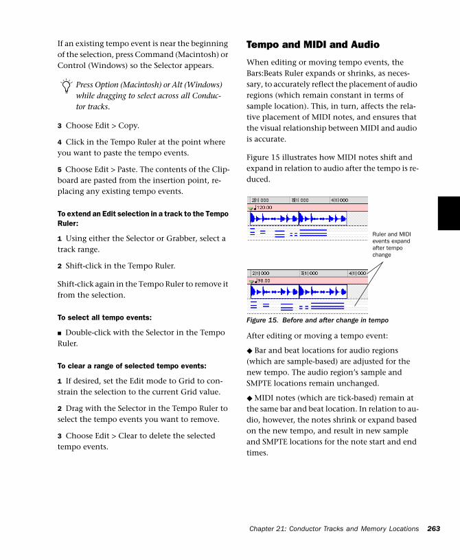
If an existing tempo event is near the beginning of the selection, press Command (Macintosh) or Control (Windows) so the Selector appears.
3 Choose Edit > Copy.
4 Click in the Tempo Ruler at the point where you want to paste the tempo events.
5 Choose Edit > Paste. The contents of the Clip-board are pasted from the insertion point, re-placing any existing tempo events.
To extend an Edit selection in a track to the Tempo Ruler:
1 Using either the Selector or Grabber, select a track range.
2 Shift-click in the Tempo Ruler.
Shift-click again in the Tempo Ruler to remove it from the selection.
To select all tempo events:
■ Double-click with the Selector in the Tempo Ruler.
To clear a range of selected tempo events:
1 If desired, set the Edit mode to Grid to con-strain the selection to the current Grid value.
2 Drag with the Selector in the Tempo Ruler to select the tempo events you want to remove.
3 Choose Edit > Clear to delete the selected tempo events.
Press Option (Macintosh) or Alt (Windows) while dragging to select across all Conduc-tor tracks.
Tempo and MIDI and Audio
When editing or moving tempo events, the Bars:Beats Ruler expands or shrinks, as neces-sary, to accurately reflect the placement of audio regions (which remain constant in terms of sample location). This, in turn, affects the rela-tive placement of MIDI notes, and ensures that the visual relationship between MIDI and audio is accurate.
Figure 15 illustrates how MIDI notes shift and expand in relation to audio after the tempo is re-duced.
After editing or moving a tempo event:
◆ Bar and beat locations for audio regions (which are sample-based) are adjusted for the new tempo. The audio region’s sample and SMPTE locations remain unchanged.
◆ MIDI notes (which are tick-based) remain at the same bar and beat location. In relation to au-dio, however, the notes shrink or expand based on the new tempo, and result in new sample and SMPTE locations for the note start and end times.
Figure 15. Before and after change in tempo
Ruler and MIDI events expand after tempo change
Chapter 21: Conductor Tracks and M
emory Locations 263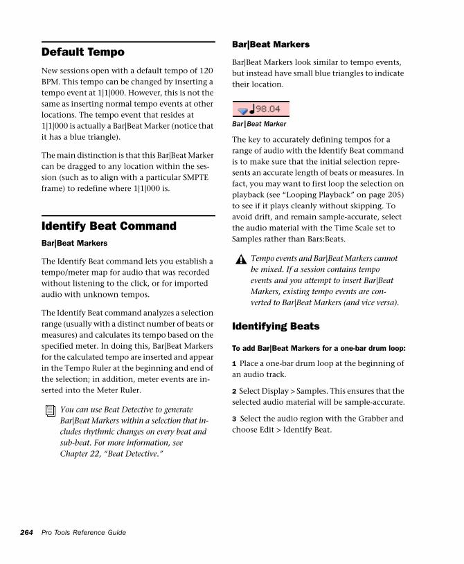
264
Default TempoNew sessions open with a default tempo of 120 BPM. This tempo can be changed by inserting a tempo event at 1|1|000. However, this is not the same as inserting normal tempo events at other locations. The tempo event that resides at 1|1|000 is actually a Bar|Beat Marker (notice that it has a blue triangle).
The main distinction is that this Bar|Beat Marker can be dragged to any location within the ses-sion (such as to align with a particular SMPTE frame) to redefine where 1|1|000 is.
Identify Beat Command Bar|Beat Markers
The Identify Beat command lets you establish a tempo/meter map for audio that was recorded without listening to the click, or for imported audio with unknown tempos.
The Identify Beat command analyzes a selection range (usually with a distinct number of beats or measures) and calculates its tempo based on the specified meter. In doing this, Bar|Beat Markers for the calculated tempo are inserted and appear in the Tempo Ruler at the beginning and end of the selection; in addition, meter events are in-serted into the Meter Ruler.
You can use Beat Detective to generate Bar|Beat Markers within a selection that in-cludes rhythmic changes on every beat and sub-beat. For more information, see Chapter 22, “Beat Detective.”
Pro Tools Reference Guide
Bar|Beat Markers
Bar|Beat Markers look similar to tempo events, but instead have small blue triangles to indicate their location.
The key to accurately defining tempos for a range of audio with the Identify Beat command is to make sure that the initial selection repre-sents an accurate length of beats or measures. In fact, you may want to first loop the selection on playback (see “Looping Playback” on page 205) to see if it plays cleanly without skipping. To avoid drift, and remain sample-accurate, select the audio material with the Time Scale set to Samples rather than Bars:Beats.
Identifying Beats
To add Bar|Beat Markers for a one-bar drum loop:
1 Place a one-bar drum loop at the beginning of an audio track.
2 Select Display > Samples. This ensures that the selected audio material will be sample-accurate.
3 Select the audio region with the Grabber and choose Edit > Identify Beat.
Bar|Beat Marker
Tempo events and Bar|Beat Markers cannot be mixed. If a session contains tempo events and you attempt to insert Bar|Beat Markers, existing tempo events are con-verted to Bar|Beat Markers (and vice versa).

4 In the Bar|Beat Markers dialog, specify the start and end points for the inserted Bar|Beat Markers. Since this example deals with a one-bar loop, enter 1|1|000 and 2|1|000.
5 If necessary, specify a time signature for the start and end range.
6 Click OK to automatically calculate the new tempo and insert the necessary Bar|Beat Markers and meter events. Any existing tempo and meter events residing within the selection are deleted.
Once the tempo has been determined for the au-dio, you can duplicate the original audio region with the Repeat command.
Identify Beat dialog
Bar|Beat Markers inserted
When working with a selection, the Identify Beat command only calculates a single tempo for the selected range. If the tempo varies from measure to measure, or beat to beat, you’ll need to use the Identify Beat command for each tempo variance (making sure to accurately de-fine a precise selection range or beat location for the tempo change).
Inserting Bar|Beat Markers One at a TimeAudio Material with Varying Tempos
You can insert Bar|Beat Markers one at a time by setting an Edit insertion point (instead of mak-ing a selection) before using the Identify Beat command. The ability to identify each beat, one at a time, is especially useful when working with audio with varying tempos.
For instance, if you have a measure that acceler-ates slightly, you could insert a Bar|Beat Marker on each beat (see Figure 16) so the tempo is ac-curately reflected.
After the Bar|Beat Markers are inserted, further adjustments in the tempo map are possible by dragging each of the Markers, as necessary, to align with the associated beat within the audio.
Figure 16. Bar|Beat Markers on each beat
Chapter 21: Conductor Tracks and Memory Locations 265
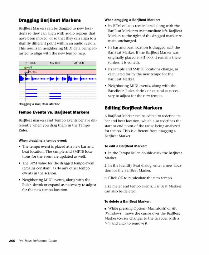
266
Dragging Bar|Beat Markers
Bar|Beat Markers can be dragged to new loca-tions so they can align with audio regions that have been moved, or so that they can align to a slightly different point within an audio region. This results in neighboring MIDI data being ad-justed to align with the new tempo map.
Tempo Events vs. Bar|Beat Markers
Bar|Beat markers and Tempo Events behave dif-ferently when you drag them in the Tempo Ruler.
When dragging a tempo event:
• The tempo event is placed at a new bar and beat location. The sample and SMPTE loca-tions for the event are updated as well.
• The BPM value for the dragged tempo event remains constant, as do any other tempo events in the session.
• Neighboring MIDI events, along with the Ruler, shrink or expand as necessary to adjust for the new tempo location.
Dragging a Bar|Beat Marker
Pro Tools Reference Guide
When dragging a Bar|Beat Marker:
• Its BPM value is recalculated along with the Bar|Beat Marker to its immediate left. Bar|Beat Markers to the right of the dragged marker re-main unchanged.
• Its bar and beat location is dragged with the Bar|Beat Marker. If the Bar|Beat Marker was originally placed at 3|1|000, it remains there (unless it is edited).
• Its sample and SMPTE locations change, as calculated for by the new tempo for the Bar|Beat Marker.
• Neighboring MIDI events, along with the Bars:Beats Ruler, shrink or expand as neces-sary to adjust for the new tempo.
Editing Bar|Beat Markers
A Bar|Beat Marker can be edited to redefine its bar and beat location, which also redefines the start or end point of the range being analyzed for tempo. This is different from dragging a Bar|Beat Marker.
To edit a Bar|Beat Marker:
1 In the Tempo Ruler, double-click the Bar|Beat Marker.
2 In the Identify Beat dialog, enter a new Loca-tion for the Bar|Beat Marker.
3 Click OK to recalculate the new tempo.
Like meter and tempo events, Bar|Beat Markers can also be deleted.
To delete a Bar|Beat Marker:
■ While pressing Option (Macintosh) or Alt (Windows), move the cursor over the Bar|Beat Marker (cursor changes to the Grabber with a “-”) and click to remove it.
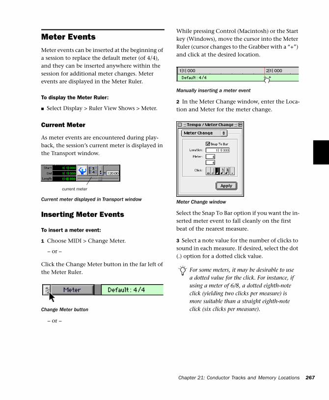
Meter EventsMeter events can be inserted at the beginning of a session to replace the default meter (of 4/4), and they can be inserted anywhere within the session for additional meter changes. Meter events are displayed in the Meter Ruler.
To display the Meter Ruler:
■ Select Display > Ruler View Shows > Meter.
Current Meter
As meter events are encountered during play-back, the session’s current meter is displayed in the Transport window.
Inserting Meter Events
To insert a meter event:
1 Choose MIDI > Change Meter.
– or –
Click the Change Meter button in the far left of the Meter Ruler.
– or –
Current meter displayed in Transport window
Change Meter button
current meter
While pressing Control (Macintosh) or the Start key (Windows), move the cursor into the Meter Ruler (cursor changes to the Grabber with a “+”) and click at the desired location.
2 In the Meter Change window, enter the Loca-tion and Meter for the meter change.
Select the Snap To Bar option if you want the in-serted meter event to fall cleanly on the first beat of the nearest measure.
3 Select a note value for the number of clicks to sound in each measure. If desired, select the dot (.) option for a dotted click value.
Manually inserting a meter event
Meter Change window
For some meters, it may be desirable to use a dotted value for the click. For instance, if using a meter of 6/8, a dotted eighth-note click (yielding two clicks per measure) is more suitable than a straight eighth-note click (six clicks per measure).
Chapter 21: Conductor Tracks and Memory Locations 267
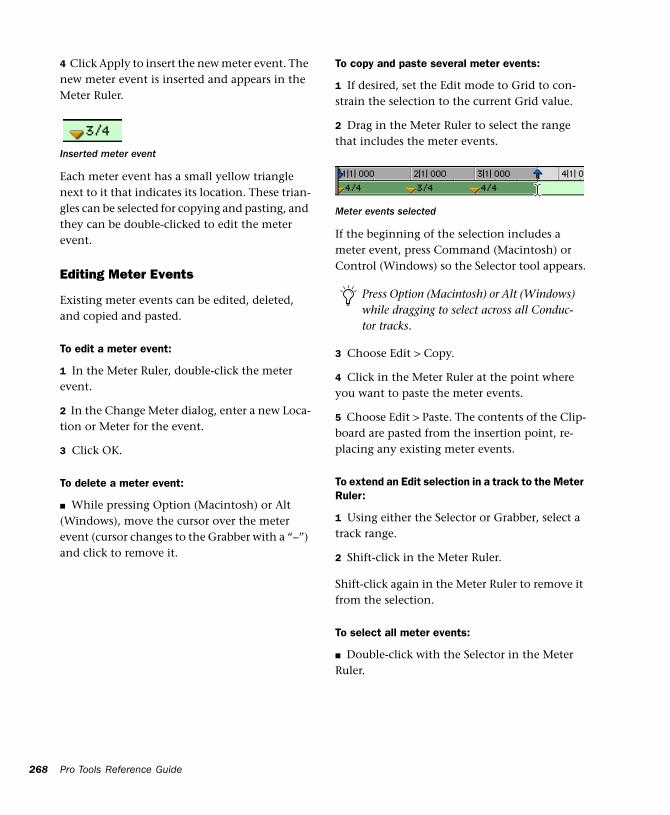
268
4 Click Apply to insert the new meter event. The new meter event is inserted and appears in the Meter Ruler.
Each meter event has a small yellow triangle next to it that indicates its location. These trian-gles can be selected for copying and pasting, and they can be double-clicked to edit the meter event.
Editing Meter Events
Existing meter events can be edited, deleted, and copied and pasted.
To edit a meter event:
1 In the Meter Ruler, double-click the meter event.
2 In the Change Meter dialog, enter a new Loca-tion or Meter for the event.
3 Click OK.
To delete a meter event:
■ While pressing Option (Macintosh) or Alt (Windows), move the cursor over the meter event (cursor changes to the Grabber with a “–”) and click to remove it.
Inserted meter event
Pro Tools Reference Guide
To copy and paste several meter events:
1 If desired, set the Edit mode to Grid to con-strain the selection to the current Grid value.
2 Drag in the Meter Ruler to select the range that includes the meter events.
If the beginning of the selection includes a meter event, press Command (Macintosh) or Control (Windows) so the Selector tool appears.
3 Choose Edit > Copy.
4 Click in the Meter Ruler at the point where you want to paste the meter events.
5 Choose Edit > Paste. The contents of the Clip-board are pasted from the insertion point, re-placing any existing meter events.
To extend an Edit selection in a track to the Meter Ruler:
1 Using either the Selector or Grabber, select a track range.
2 Shift-click in the Meter Ruler.
Shift-click again in the Meter Ruler to remove it from the selection.
To select all meter events:
■ Double-click with the Selector in the Meter Ruler.
Meter events selected
Press Option (Macintosh) or Alt (Windows) while dragging to select across all Conduc-tor tracks.
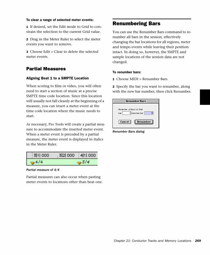
To clear a range of selected meter events:
1 If desired, set the Edit mode to Grid to con-strain the selection to the current Grid value.
2 Drag in the Meter Ruler to select the meter events you want to remove.
3 Choose Edit > Clear to delete the selected meter events.
Partial Measures
Aligning Beat 1 to a SMPTE Location
When scoring to film or video, you will often need to start a section of music at a precise SMPTE time code location. Since this location will usually not fall cleanly at the beginning of a measure, you can insert a meter event at the time code location where the music needs to start.
As necessary, Pro Tools will create a partial mea-sure to accommodate the inserted meter event. When a meter event is preceded by a partial measure, the meter event is displayed in italics in the Meter Ruler.
Partial measures can also occur when pasting meter events to locations other than beat one.
Partial measure of 4/4
Renumbering BarsYou can use the Renumber Bars command to re-number all bars in the session, effectively changing the bar locations for all regions, meter and tempo events while leaving their position intact. In doing so, however, the SMPTE and sample locations of the session data are not changed.
To renumber bars:
1 Choose MIDI > Renumber Bars.
2 Specify the bar you want to renumber, along with the new bar number, then click Renumber.
Renumber Bars dialog
Chapter 21: Conductor Tracks and Memory Locations 269
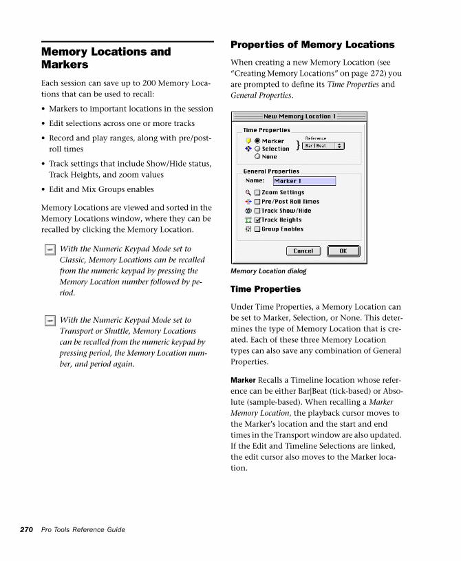
270
Memory Locations and MarkersEach session can save up to 200 Memory Loca-tions that can be used to recall:
• Markers to important locations in the session
• Edit selections across one or more tracks
• Record and play ranges, along with pre/post-roll times
• Track settings that include Show/Hide status, Track Heights, and zoom values
• Edit and Mix Groups enables
Memory Locations are viewed and sorted in the Memory Locations window, where they can be recalled by clicking the Memory Location.
With the Numeric Keypad Mode set to Classic, Memory Locations can be recalled from the numeric keypad by pressing the Memory Location number followed by pe-riod.
With the Numeric Keypad Mode set to Transport or Shuttle, Memory Locations can be recalled from the numeric keypad by pressing period, the Memory Location num-ber, and period again.
Pro Tools Reference Guide
Properties of Memory Locations
When creating a new Memory Location (see “Creating Memory Locations” on page 272) you are prompted to define its Time Properties and General Properties.
Time Properties
Under Time Properties, a Memory Location can be set to Marker, Selection, or None. This deter-mines the type of Memory Location that is cre-ated. Each of these three Memory Location types can also save any combination of General Properties.
Marker Recalls a Timeline location whose refer-ence can be either Bar|Beat (tick-based) or Abso-lute (sample-based). When recalling a Marker Memory Location, the playback cursor moves to the Marker’s location and the start and end times in the Transport window are also updated. If the Edit and Timeline Selections are linked, the edit cursor also moves to the Marker loca-tion.
Memory Location dialog
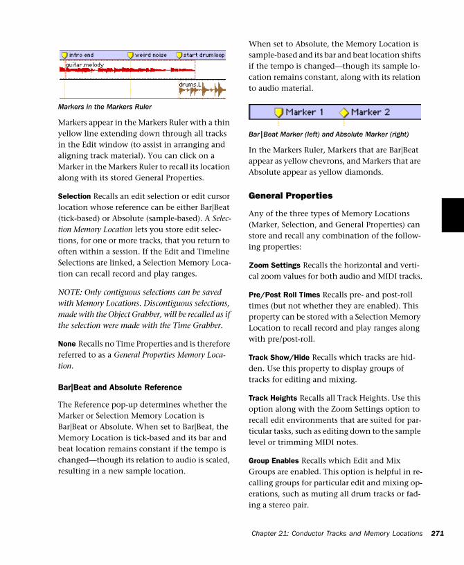
Markers appear in the Markers Ruler with a thin yellow line extending down through all tracks in the Edit window (to assist in arranging and aligning track material). You can click on a Marker in the Markers Ruler to recall its location along with its stored General Properties.
Selection Recalls an edit selection or edit cursor location whose reference can be either Bar|Beat (tick-based) or Absolute (sample-based). A Selec-tion Memory Location lets you store edit selec-tions, for one or more tracks, that you return to often within a session. If the Edit and Timeline Selections are linked, a Selection Memory Loca-tion can recall record and play ranges.
NOTE: Only contiguous selections can be saved with Memory Locations. Discontiguous selections, made with the Object Grabber, will be recalled as if the selection were made with the Time Grabber.
None Recalls no Time Properties and is therefore referred to as a General Properties Memory Loca-tion.
Bar|Beat and Absolute Reference
The Reference pop-up determines whether the Marker or Selection Memory Location is Bar|Beat or Absolute. When set to Bar|Beat, the Memory Location is tick-based and its bar and beat location remains constant if the tempo is changed—though its relation to audio is scaled, resulting in a new sample location.
Markers in the Markers Ruler
When set to Absolute, the Memory Location is sample-based and its bar and beat location shifts if the tempo is changed—though its sample lo-cation remains constant, along with its relation to audio material.
In the Markers Ruler, Markers that are Bar|Beat appear as yellow chevrons, and Markers that are Absolute appear as yellow diamonds.
General Properties
Any of the three types of Memory Locations (Marker, Selection, and General Properties) can store and recall any combination of the follow-ing properties:
Zoom Settings Recalls the horizontal and verti-cal zoom values for both audio and MIDI tracks.
Pre/Post Roll Times Recalls pre- and post-roll times (but not whether they are enabled). This property can be stored with a Selection Memory Location to recall record and play ranges along with pre/post-roll.
Track Show/Hide Recalls which tracks are hid-den. Use this property to display groups of tracks for editing and mixing.
Track Heights Recalls all Track Heights. Use this option along with the Zoom Settings option to recall edit environments that are suited for par-ticular tasks, such as editing down to the sample level or trimming MIDI notes.
Group Enables Recalls which Edit and Mix Groups are enabled. This option is helpful in re-calling groups for particular edit and mixing op-erations, such as muting all drum tracks or fad-ing a stereo pair.
Bar|Beat Marker (left) and Absolute Marker (right)
Chapter 21: Conductor Tracks and Memory Locations 271
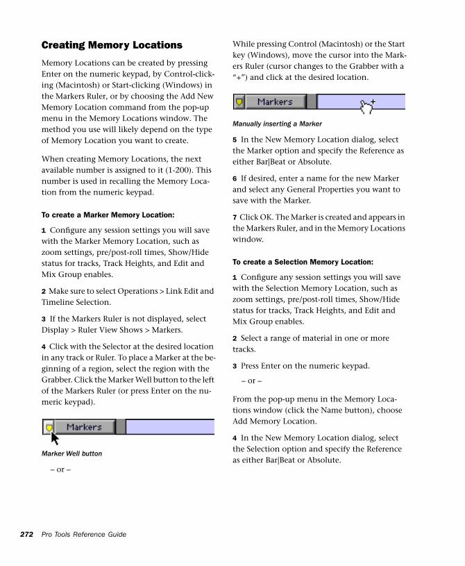
272
Creating Memory Locations
Memory Locations can be created by pressing Enter on the numeric keypad, by Control-click-ing (Macintosh) or Start-clicking (Windows) in the Markers Ruler, or by choosing the Add New Memory Location command from the pop-up menu in the Memory Locations window. The method you use will likely depend on the type of Memory Location you want to create.
When creating Memory Locations, the next available number is assigned to it (1-200). This number is used in recalling the Memory Loca-tion from the numeric keypad.
To create a Marker Memory Location:
1 Configure any session settings you will save with the Marker Memory Location, such as zoom settings, pre/post-roll times, Show/Hide status for tracks, Track Heights, and Edit and Mix Group enables.
2 Make sure to select Operations > Link Edit and Timeline Selection.
3 If the Markers Ruler is not displayed, select Display > Ruler View Shows > Markers.
4 Click with the Selector at the desired location in any track or Ruler. To place a Marker at the be-ginning of a region, select the region with the Grabber. Click the Marker Well button to the left of the Markers Ruler (or press Enter on the nu-meric keypad).
– or –
Marker Well button
Pro Tools Reference Guide
While pressing Control (Macintosh) or the Start key (Windows), move the cursor into the Mark-ers Ruler (cursor changes to the Grabber with a “+”) and click at the desired location.
5 In the New Memory Location dialog, select the Marker option and specify the Reference as either Bar|Beat or Absolute.
6 If desired, enter a name for the new Marker and select any General Properties you want to save with the Marker.
7 Click OK. The Marker is created and appears in the Markers Ruler, and in the Memory Locations window.
To create a Selection Memory Location:
1 Configure any session settings you will save with the Selection Memory Location, such as zoom settings, pre/post-roll times, Show/Hide status for tracks, Track Heights, and Edit and Mix Group enables.
2 Select a range of material in one or more tracks.
3 Press Enter on the numeric keypad.
– or –
From the pop-up menu in the Memory Loca-tions window (click the Name button), choose Add Memory Location.
4 In the New Memory Location dialog, select the Selection option and specify the Reference as either Bar|Beat or Absolute.
Manually inserting a Marker
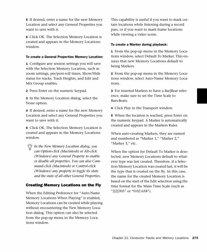
5 If desired, enter a name for the new Memory Location and select any General Properties you want to save with it.
6 Click OK. The Selection Memory Location is created and appears in the Memory Locations window.
To create a General Properties Memory Location:
1 Configure any session settings you will save with the Selection Memory Location, such as zoom settings, pre/post-roll times, Show/Hide status for tracks, Track Heights, and Edit and Mix Group enables.
2 Press Enter on the numeric keypad.
3 In the Memory Location dialog, select the None option.
4 If desired, enter a name for the new Memory Location and select any General Properties you want to save with it.
5 Click OK. The Selection Memory Location is created and appears in the Memory Locations window.
Creating Memory Locations on the Fly
When the Editing Preference for “Auto-Name Memory Locations When Playing” is enabled, Memory Locations can be created while playing without encountering the New Memory Loca-tion dialog. This option can also be selected from the pop-up menu in the Memory Loca-tions window.
In the New Memory Location dialog, you can Option-click (Macintosh) or Alt-click (Windows) any General Property to enable or disable all properties. You can also Com-mand-click (Macintosh) or Control-click (Windows) any property to toggle its state and the state of all other General Properties.
This capability is useful if you want to mark cer-tain locations while listening during a record pass, or if you want to mark frame locations while viewing a video scene.
To create a Marker during playback:
1 From the pop-up menu in the Memory Loca-tions window, select Default To Marker. This en-sures that new Memory Locations default to being Markers.
2 From the pop-up menu in the Memory Loca-tions window, select Auto-Name Memory Loca-tions.
3 For inserted Markers to have a Bar|Beat refer-ence, make sure to set the Time Scale to Bars:Beats.
4 Click Play in the Transport window.
5 When the location is reached, press Enter on the numeric keypad. A Marker is automatically created and appears in the Markers Ruler.
When auto-creating Markers, they are named and numbered as “Marker 1,” “Marker 2,” “Marker 3,” etc.
When the option for Default To Marker is dese-lected, new Memory Locations default to what-ever type was last created. Therefore, if a Selec-tion Memory Location was created last, it will be the type that is created on the fly. In this case, the name for the created Memory Location is based on the start of the Edit selection using the time format for the Main Time Scale (such as “2|2|305” or “0:02.658”).
Chapter 21: Conductor Tracks and Memory Locations 273
274
Recalling Memory Locations
Memory Locations can be recalled from the Memory Locations window and from the nu-meric keypad. In addition, Marker Memory Se-lections can be recalled by clicking them in the Markers Ruler.
To recall a Memory Location:
1 If the Memory Locations window is not al-ready open, choose Windows > Show Memory Locations to display it.
2 If recalling a Selection Memory Location that will define a record or play range, make sure to select Operations > Link Edit and Timeline Se-lection.
3 In the Memory Locations window, click the Memory Location to recall it.
– or –
With the Numeric Keypad Mode set to Classic, press the Memory Location number followed by period.
– or –
With the Numeric Keypad Mode set to Trans-port or Shuttle, press period, the Memory Loca-tion number, and period again.
NOTE: When recalling a Memory Location from the numeric keypad, the Memory Locations win-dow does not need to be open.
To recall a Marker from the Markers Ruler:
1 If the Markers Ruler is not displayed, select Display > Ruler View Shows > Markers.
2 Click on the Marker. The playback cursor lo-cates to the Marker and any General Properties stored with the Marker are recalled.
Pro Tools Reference Guide
NOTE: Even if the Markers Ruler is not displayed, Markers can be recalled from the Memory Loca-tions window, or from the numeric keypad.
Editing Memory Locations
Memory Locations can be renamed, edited, de-leted, and copied and pasted.
To rename a Memory Location:
1 In the Memory Locations window, double-click the Memory Location you want to rename.
– or –
If renaming a Marker Memory Location, double-click the Marker in the Markers Ruler.
2 Enter the new name for the Memory Location and click OK.
To redefine the General Properties stored with a Memory Location:
1 As desired, make changes to the session’s zoom settings, pre/post-roll times, Show/Hide status of tracks, Track Heights, and Group En-ables.
2 In the Memory Locations window, Control-click (Macintosh) or Right-click (Windows) the Memory Location you want to redefine.
– or –
If changing a Marker Memory Location, Con-trol-click (Macintosh) or Right-click (Windows) the Marker in the Markers Ruler.
3 In the Memory Location dialog, select the General Properties you want to save with the Memory Location.
4 Enter a new name for the Memory Location, if desired, and click OK.
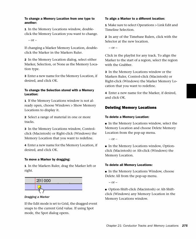
To change a Memory Location from one type to another:
1 In the Memory Locations window, double-click the Memory Location you want to change.
– or –
If changing a Marker Memory Location, double-click the Marker in the Markers Ruler.
2 In the Memory Location dialog, select either Marker, Selection, or None as the Memory Loca-tion type.
3 Enter a new name for the Memory Location, if desired, and click OK.
To change the Selection stored with a Memory Location:
1 If the Memory Locations window is not al-ready open, choose Windows > Show Memory Locations to display it.
2 Select a range of material in one or more tracks.
3 In the Memory Locations window, Control-click (Macintosh) or Right-click (Windows) the Memory Location that you want to redefine.
4 Enter a new name for the Memory Location, if desired, and click OK.
To move a Marker by dragging:
1 In the Markers Ruler, drag the Marker left or right.
If the Edit mode is set to Grid, the dragged event snaps to the current Grid value. If using Spot mode, the Spot dialog opens.
Dragging a Marker
To align a Marker to a different location:
1 Make sure to select Operations > Link Edit and Timeline Selection.
2 In any of the Timebase Rulers, click with the Selector at the new location.
– or –
Click in the playlist for any track. To align the Marker to the start of a region, select the region with the Grabber.
3 In the Memory Locations window or the Markers Ruler, Control-click (Macintosh) or Right-click (Windows) the Marker Memory Lo-cation that you want to redefine.
4 Enter a new name for the Marker, if desired, and click OK.
Deleting Memory Locations
To delete a Memory Location:
■ In the Memory Locations window, select the Memory Location and choose Delete Memory Location from the pop-up menu.
– or –
■ In the Memory Locations window, Option-click (Macintosh) or Alt-click (Windows) the Memory Location.
To delete all Memory Locations:
■ In the Memory Locations Window, choose Delete All from the pop-up menu.
– or –
■ Option-Shift-click (Macintosh) or Alt-Shift-click (Windows) any Memory Location in the Memory Locations window.
Chapter 21: Conductor Tracks and Memory Locations 275
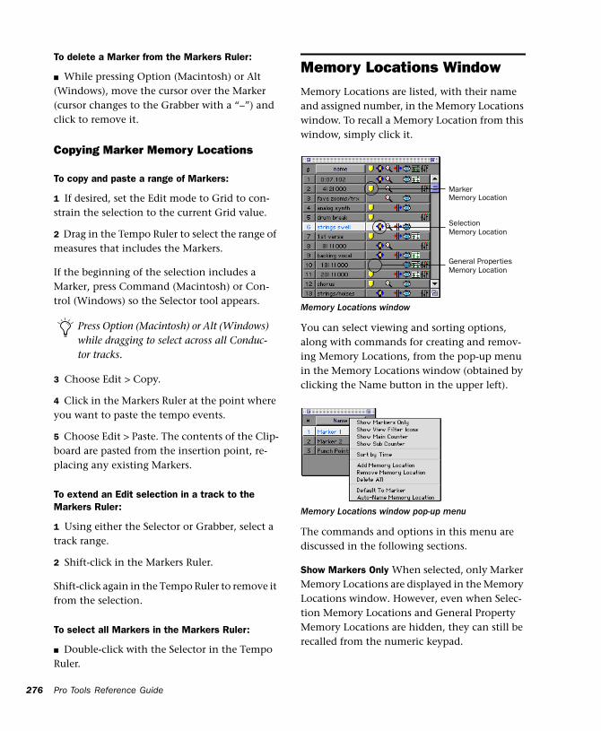
276
To delete a Marker from the Markers Ruler:
■ While pressing Option (Macintosh) or Alt (Windows), move the cursor over the Marker (cursor changes to the Grabber with a “–”) and click to remove it.
Copying Marker Memory Locations
To copy and paste a range of Markers:
1 If desired, set the Edit mode to Grid to con-strain the selection to the current Grid value.
2 Drag in the Tempo Ruler to select the range of measures that includes the Markers.
If the beginning of the selection includes a Marker, press Command (Macintosh) or Con-trol (Windows) so the Selector tool appears.
3 Choose Edit > Copy.
4 Click in the Markers Ruler at the point where you want to paste the tempo events.
5 Choose Edit > Paste. The contents of the Clip-board are pasted from the insertion point, re-placing any existing Markers.
To extend an Edit selection in a track to the Markers Ruler:
1 Using either the Selector or Grabber, select a track range.
2 Shift-click in the Markers Ruler.
Shift-click again in the Tempo Ruler to remove it from the selection.
To select all Markers in the Markers Ruler:
■ Double-click with the Selector in the Tempo Ruler.
Press Option (Macintosh) or Alt (Windows) while dragging to select across all Conduc-tor tracks.
Pro Tools Reference Guide
Memory Locations WindowMemory Locations are listed, with their name and assigned number, in the Memory Locations window. To recall a Memory Location from this window, simply click it.
You can select viewing and sorting options, along with commands for creating and remov-ing Memory Locations, from the pop-up menu in the Memory Locations window (obtained by clicking the Name button in the upper left).
The commands and options in this menu are discussed in the following sections.
Show Markers Only When selected, only Marker Memory Locations are displayed in the Memory Locations window. However, even when Selec-tion Memory Locations and General Property Memory Locations are hidden, they can still be recalled from the numeric keypad.
Memory Locations window
Memory Locations window pop-up menu
Marker
SelectionMemory Location
General PropertiesMemory Location
Memory Location

Show View Filter Icons When selected, the Memory Locations window provides an icon-based “view filter” that allows you to show or hide Memory Locations based on the properties they contain. To show or hide Memory Loca-tions containing a specific property, click the appropriate icon.
If an icon is disabled, all Memory Locations as-sociated with that property are hidden. How-ever, if a Memory Location contains other prop-erties for an icon that is enabled, it is still displayed. When a view icon is enabled, it ap-pears in color. When it is disabled, it appears gray.
In addition, the view filter provides a handy ref-erence for which properties are stored in each Memory Location (indicated by a row of icons for each Memory Location).
Memory Locations View Filter
Memory Locations window with view filter icons
Marker
SelectionMemory Location
Zoom
Pre/Post-Roll
Show/HideTrack HeightsSettings
ActiveGroups
Show Main/Sub Counter When selected, a col-umn appears in the Memory Locations window that displays the locations for Markers, and the start times for Selection Memory Locations. General Property Memory Locations display nothing in this column.
You can click at the top of these columns for a pop-up menu that will let you change the Main and Sub Time Scale.
Sort by Time When selected, Markers are sorted by their order in the Timeline, followed by Se-lection and General Properties Memory Loca-tions, which are listed in the order in which they were created.
When Sort by Time is deselected, all Memory Locations are listed in the order of their assigned numbers.
Add Memory Location Choose this command to create a new Memory Location.
Remove Memory Location Deletes the currently selected Memory Location in the Memory Loca-tions window.
Delete All Deletes all Memory Locations (Marker, Selection, and General Property) in the session.
Default To Marker When selected, new Memory Locations default to Markers, though in the New Memory Location dialog you can still define the new Memory Location as one of the other types.
Main/Sub Counters in Memory Locations window
SubMain Time Scale Time Scale
Chapter 21: Conductor Tracks and Memory Locations 277
278
Auto-Name Memory Location When selected, Memory Locations are created automatically without encountering the New Memory Loca-tion dialog. If the Default To Marker option is selected, a Marker Memory Location is auto-cre-ated. Otherwise, the Memory Location type is determined by whatever type (Marker, Selec-tion, or None) was created last.
Pro Tools Reference Guide
Chapter 22: Beat Detective
Beat Detective RequirementsBeat Detective is only available with Pro Tools TDM systems. It does not appear in Pro Tools LE.
RAM Requirements for Beat Detective
Beat Detective operations can require a large amount of RAM, especially when working with multiple tracks and lengthy selections.
To avoid low memory situations with Beat Detective, do the following:
■ Macintosh users should substantially increase the RAM allocated to Pro Tools . Under extreme usage situations (eight or more tracks with selec-tions of five minutes or longer), you should allo-cate 100 MB, or even more, to the Pro Tools application.
■ If your computer does not have the extra RAM, work with shorter selections, or individual tracks.
– or –
■ Set the Editing Preference for Levels of Undo to a smaller value (see “Levels of Undo and RAM” on page 175). Memory-intensive editing operations, such as Edit Smoothing with Beat Detective, can use up a large amount of memory when in the Undo queue.
About Beat DetectiveBeat Detective can automatically detect peak transients in audio selections, so you can extract tempo information from the audio material, or so that you can conform the audio material to the session’s existing tempo map.
Beat Detective involves the following steps:
1 Define a selection of audio material, on a sin-gle mono track, multi-channel track, or across multiple tracks.
2 Adjust the Detection parameters so that verti-cal beat triggers appear in Edit window, based on the peak transients detected in the selection.
3 Generate Bar|Beat Markers based on the beat triggers, thereby extracting a tempo map from the selection and using it for the session.
– or –
4 Separate and automatically create new re-gions, representing beats or sub-beats, based on the beat triggers . You can then conform the new regions to the session’s existing tempo map, followed by automatic edit smoothing, if necessary.
Chapter 22: Beat Detective 279
280
Beat Detective and the Source Material
Beat Detective is most effective with rhythmic audio material that has strong percussive at-tacks. It should work well with most instru-ments used in pop music, such as drums, guitar, and bass. Beat Detective will be less successful with audio material that has soft attacks, or le-gato phrasing, such as strings and vocals.
While Beat Detective has intelligent analysis al-gorithms for detecting rhythmic material, some material may be too far off the rhythmic grid, or have tempo changes that are too varied, to be useful with Beat Detective.
Applications for Beat Detective
Following are some useful applications for Beat Detective.
Extracting Tempo and Grooves from Audio
Beat Detective can convert beat triggers to Bar|Beat Markers, which makes it possible to ex-tract tempo from audio that was recorded with-out listening to a click—even if the audio con-tains varying tempos, or material that is swung.
Once the Bar|Beat Markers have been generated from the source audio, other audio regions and MIDI tracks in the session can be quantized to it.
Conforming Audio to an Existing Tempo Map
If your session already has the right tempo, you can conform audio with a different tempo, or with varying tempos, to the session’s tempo. If desired, the conformed audio can retain a per-centage of its original feel, and you can increase or reduce the amount of swing in the con-formed material.
Pro Tools Reference Guide
“Tightening Up” an Audio Performance
Beat Detective can improve the timing of some audio material by calculating and extracting its average tempo, and then conforming its rhyth-mic components (regions separated with Beat Detective) to the session’s tempo map. You can even retain some of the original feel of the mate-rial.
Loop Matching
Since Beat Detective can extract tempo and beat information from audio, and conform audio to an existing tempo, this makes it very useful for aligning loops with different tempos or feels. If one loop has a subtly different feel or groove, you can potentially impose that groove on an-other loop.
Remixes
Beat Detective can be used for remixes. It can ex-tract tempo from the original drum tracks, or in some instances the original stereo mix. New tracks, audio or MIDI, can then be conformed to the original material, or the original material can be conformed to new drum tracks, achiev-ing an entirely new feel.
Smoothing Post-Production Edits
Beat Detective’s Edit Smoothing can be used to automatically clean up foley tracks that contain many regions that need to be trimmed and crossfaded, effectively removing the gaps of si-lence between the regions (so you can retain the room tone throughout the track).
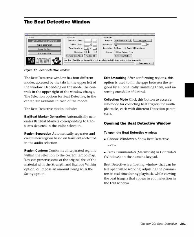
The Beat Detective Window
Figure 17. Beat Detective window
The Beat Detective window has four different modes, accessed by the tabs in the upper left of the window. Depending on the mode, the con-trols in the upper right of the window change. The Selection options for Beat Detective, in the center, are available in each of the modes.
The Beat Detective modes include:
Bar|Beat Marker Generation Automatically gen-erates Bar|Beat Markers corresponding to tran-sients detected in the audio selection.
Region Separation Automatically separates and creates new regions based on transients detected in the audio selection.
Region Conform Conforms all separated regions within the selection to the current tempo map. You can preserve some of the original feel of the material with the Strength and Exclude Within option, or impose an amount swing with the Swing option.
Edit Smoothing After conforming regions, this option is used to fill the gaps between the re-gions by automatically trimming them, and in-serting crossfades if desired.
Collection Mode Click this button to access a sub-mode for collecting beat triggers for multi-ple tracks, each with different Detection param-eters.
Opening the Beat Detective Window
To open the Beat Detective window:
■ Choose Windows > Show Beat Detective.
– or –
■ Press Command+8 (Macintosh) or Control+8 (Windows) on the numeric keypad.
Beat Detective is a floating window that can be left open while working, adjusting the parame-ters in real time during playback, while viewing the beat triggers that appear in your selection in the Edit window.
Chapter 22: Beat Detective 281
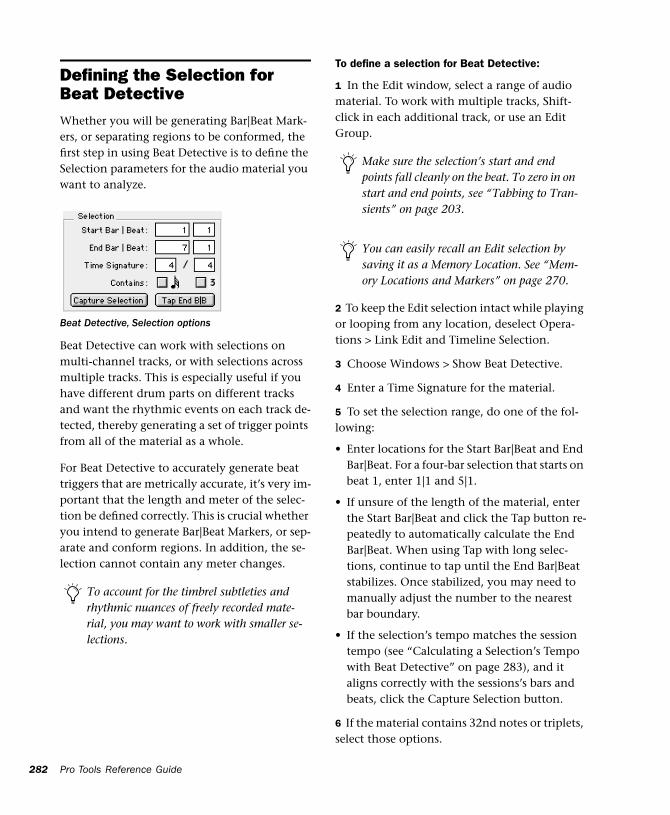
282
Defining the Selection for Beat DetectiveWhether you will be generating Bar|Beat Mark-ers, or separating regions to be conformed, the first step in using Beat Detective is to define the Selection parameters for the audio material you want to analyze.
Beat Detective can work with selections on multi-channel tracks, or with selections across multiple tracks. This is especially useful if you have different drum parts on different tracks and want the rhythmic events on each track de-tected, thereby generating a set of trigger points from all of the material as a whole.
For Beat Detective to accurately generate beat triggers that are metrically accurate, it’s very im-portant that the length and meter of the selec-tion be defined correctly. This is crucial whether you intend to generate Bar|Beat Markers, or sep-arate and conform regions. In addition, the se-lection cannot contain any meter changes.
Beat Detective, Selection options
To account for the timbrel subtleties and rhythmic nuances of freely recorded mate-rial, you may want to work with smaller se-lections.
Pro Tools Reference Guide
To define a selection for Beat Detective:
1 In the Edit window, select a range of audio material. To work with multiple tracks, Shift-click in each additional track, or use an Edit Group.
2 To keep the Edit selection intact while playing or looping from any location, deselect Opera-tions > Link Edit and Timeline Selection.
3 Choose Windows > Show Beat Detective.
4 Enter a Time Signature for the material.
5 To set the selection range, do one of the fol-lowing:
• Enter locations for the Start Bar|Beat and End Bar|Beat. For a four-bar selection that starts on beat 1, enter 1|1 and 5|1.
• If unsure of the length of the material, enter the Start Bar|Beat and click the Tap button re-peatedly to automatically calculate the End Bar|Beat. When using Tap with long selec-tions, continue to tap until the End Bar|Beat stabilizes. Once stabilized, you may need to manually adjust the number to the nearest bar boundary.
• If the selection’s tempo matches the session tempo (see “Calculating a Selection’s Tempo with Beat Detective” on page 283), and it aligns correctly with the sessions’s bars and beats, click the Capture Selection button.
6 If the material contains 32nd notes or triplets, select those options.
Make sure the selection’s start and end points fall cleanly on the beat. To zero in on start and end points, see “Tabbing to Tran-sients” on page 203.
You can easily recall an Edit selection by saving it as a Memory Location. See “Mem-ory Locations and Markers” on page 270.
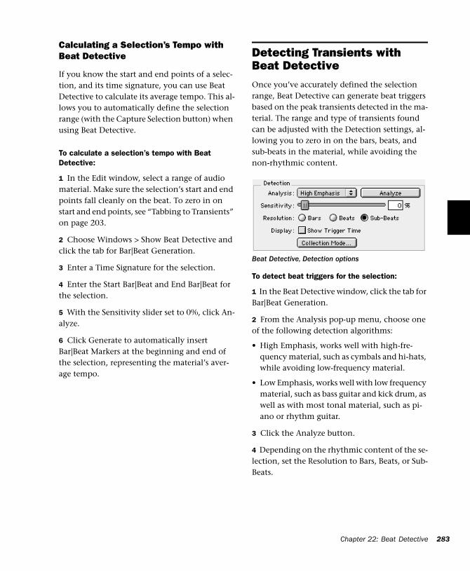
Calculating a Selection’s Tempo with Beat Detective
If you know the start and end points of a selec-tion, and its time signature, you can use Beat Detective to calculate its average tempo. This al-lows you to automatically define the selection range (with the Capture Selection button) when using Beat Detective.
To calculate a selection’s tempo with Beat Detective:
1 In the Edit window, select a range of audio material. Make sure the selection’s start and end points fall cleanly on the beat. To zero in on start and end points, see “Tabbing to Transients” on page 203.
2 Choose Windows > Show Beat Detective and click the tab for Bar|Beat Generation.
3 Enter a Time Signature for the selection.
4 Enter the Start Bar|Beat and End Bar|Beat for the selection.
5 With the Sensitivity slider set to 0%, click An-alyze.
6 Click Generate to automatically insert Bar|Beat Markers at the beginning and end of the selection, representing the material’s aver-age tempo.
Detecting Transients with Beat DetectiveOnce you’ve accurately defined the selection range, Beat Detective can generate beat triggers based on the peak transients detected in the ma-terial. The range and type of transients found can be adjusted with the Detection settings, al-lowing you to zero in on the bars, beats, and sub-beats in the material, while avoiding the non-rhythmic content.
To detect beat triggers for the selection:
1 In the Beat Detective window, click the tab for Bar|Beat Generation.
2 From the Analysis pop-up menu, choose one of the following detection algorithms:
• High Emphasis, works well with high-fre-quency material, such as cymbals and hi-hats, while avoiding low-frequency material.
• Low Emphasis, works well with low frequency material, such as bass guitar and kick drum, as well as with most tonal material, such as pi-ano or rhythm guitar.
3 Click the Analyze button.
4 Depending on the rhythmic content of the se-lection, set the Resolution to Bars, Beats, or Sub-Beats.
Beat Detective, Detection options
Chapter 22: Beat Detective 283
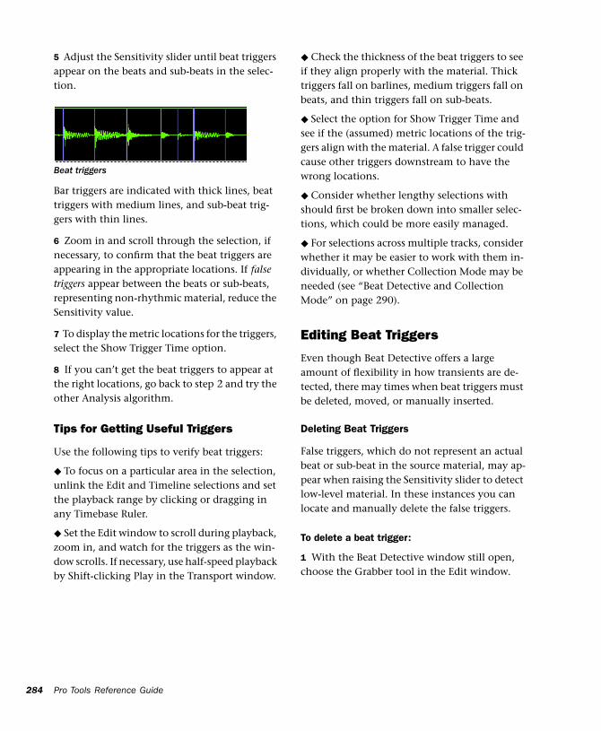
284
5 Adjust the Sensitivity slider until beat triggers appear on the beats and sub-beats in the selec-tion.
Bar triggers are indicated with thick lines, beat triggers with medium lines, and sub-beat trig-gers with thin lines.
6 Zoom in and scroll through the selection, if necessary, to confirm that the beat triggers are appearing in the appropriate locations. If false triggers appear between the beats or sub-beats, representing non-rhythmic material, reduce the Sensitivity value.
7 To display the metric locations for the triggers, select the Show Trigger Time option.
8 If you can’t get the beat triggers to appear at the right locations, go back to step 2 and try the other Analysis algorithm.
Tips for Getting Useful Triggers
Use the following tips to verify beat triggers:
◆ To focus on a particular area in the selection, unlink the Edit and Timeline selections and set the playback range by clicking or dragging in any Timebase Ruler.
◆ Set the Edit window to scroll during playback, zoom in, and watch for the triggers as the win-dow scrolls. If necessary, use half-speed playback by Shift-clicking Play in the Transport window.
Beat triggers
Pro Tools Reference Guide
◆ Check the thickness of the beat triggers to see if they align properly with the material. Thick triggers fall on barlines, medium triggers fall on beats, and thin triggers fall on sub-beats.
◆ Select the option for Show Trigger Time and see if the (assumed) metric locations of the trig-gers align with the material. A false trigger could cause other triggers downstream to have the wrong locations.
◆ Consider whether lengthy selections with should first be broken down into smaller selec-tions, which could be more easily managed.
◆ For selections across multiple tracks, consider whether it may be easier to work with them in-dividually, or whether Collection Mode may be needed (see “Beat Detective and Collection Mode” on page 290).
Editing Beat Triggers
Even though Beat Detective offers a large amount of flexibility in how transients are de-tected, there may times when beat triggers must be deleted, moved, or manually inserted.
Deleting Beat Triggers
False triggers, which do not represent an actual beat or sub-beat in the source material, may ap-pear when raising the Sensitivity slider to detect low-level material. In these instances you can locate and manually delete the false triggers.
To delete a beat trigger:
1 With the Beat Detective window still open, choose the Grabber tool in the Edit window.
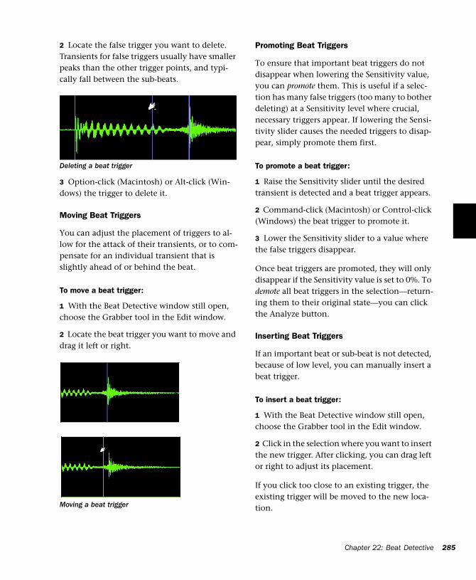
2 Locate the false trigger you want to delete. Transients for false triggers usually have smaller peaks than the other trigger points, and typi-cally fall between the sub-beats.
3 Option-click (Macintosh) or Alt-click (Win-dows) the trigger to delete it.
Moving Beat Triggers
You can adjust the placement of triggers to al-low for the attack of their transients, or to com-pensate for an individual transient that is slightly ahead of or behind the beat.
To move a beat trigger:
1 With the Beat Detective window still open, choose the Grabber tool in the Edit window.
2 Locate the beat trigger you want to move and drag it left or right.
Deleting a beat trigger
Moving a beat trigger
Promoting Beat Triggers
To ensure that important beat triggers do not disappear when lowering the Sensitivity value, you can promote them. This is useful if a selec-tion has many false triggers (too many to bother deleting) at a Sensitivity level where crucial, necessary triggers appear. If lowering the Sensi-tivity slider causes the needed triggers to disap-pear, simply promote them first.
To promote a beat trigger:
1 Raise the Sensitivity slider until the desired transient is detected and a beat trigger appears.
2 Command-click (Macintosh) or Control-click (Windows) the beat trigger to promote it.
3 Lower the Sensitivity slider to a value where the false triggers disappear.
Once beat triggers are promoted, they will only disappear if the Sensitivity value is set to 0%. To demote all beat triggers in the selection—return-ing them to their original state—you can click the Analyze button.
Inserting Beat Triggers
If an important beat or sub-beat is not detected, because of low level, you can manually insert a beat trigger.
To insert a beat trigger:
1 With the Beat Detective window still open, choose the Grabber tool in the Edit window.
2 Click in the selection where you want to insert the new trigger. After clicking, you can drag left or right to adjust its placement.
If you click too close to an existing trigger, the existing trigger will be moved to the new loca-tion.
Chapter 22: Beat Detective 285
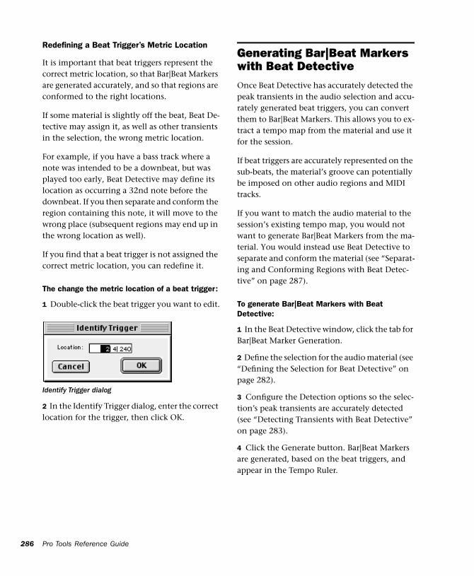
286
Redefining a Beat Trigger’s Metric Location
It is important that beat triggers represent the correct metric location, so that Bar|Beat Markers are generated accurately, and so that regions are conformed to the right locations.
If some material is slightly off the beat, Beat De-tective may assign it, as well as other transients in the selection, the wrong metric location.
For example, if you have a bass track where a note was intended to be a downbeat, but was played too early, Beat Detective may define its location as occurring a 32nd note before the downbeat. If you then separate and conform the region containing this note, it will move to the wrong place (subsequent regions may end up in the wrong location as well).
If you find that a beat trigger is not assigned the correct metric location, you can redefine it.
The change the metric location of a beat trigger:
1 Double-click the beat trigger you want to edit.
2 In the Identify Trigger dialog, enter the correct location for the trigger, then click OK.
Identify Trigger dialog
Pro Tools Reference Guide
Generating Bar|Beat Markers with Beat DetectiveOnce Beat Detective has accurately detected the peak transients in the audio selection and accu-rately generated beat triggers, you can convert them to Bar|Beat Markers. This allows you to ex-tract a tempo map from the material and use it for the session.
If beat triggers are accurately represented on the sub-beats, the material’s groove can potentially be imposed on other audio regions and MIDI tracks.
If you want to match the audio material to the session’s existing tempo map, you would not want to generate Bar|Beat Markers from the ma-terial. You would instead use Beat Detective to separate and conform the material (see “Separat-ing and Conforming Regions with Beat Detec-tive” on page 287).
To generate Bar|Beat Markers with Beat Detective:
1 In the Beat Detective window, click the tab for Bar|Beat Marker Generation.
2 Define the selection for the audio material (see “Defining the Selection for Beat Detective” on page 282).
3 Configure the Detection options so the selec-tion’s peak transients are accurately detected (see “Detecting Transients with Beat Detective” on page 283).
4 Click the Generate button. Bar|Beat Markers are generated, based on the beat triggers, and appear in the Tempo Ruler.
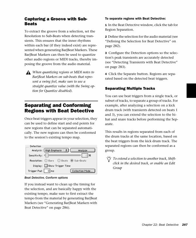
Capturing a Groove with Sub-Beats
To extract the groove from a selection, set the Resolution to Sub-Beats when detecting tran-sients. This ensures that the inner rhythms within each bar (if they indeed exist) are repre-sented when generating Bar|Beat Markers. These Bar|Beat Markers can then be used to quantize other audio regions or MIDI tracks, thereby im-posing the groove from the audio material.
Separating and Conforming Regions with Beat DetectiveOnce beat triggers appear in your selection, they can be used to define start and end points for new regions that can be separated automati-cally. The new regions can then be conformed to the session’s existing tempo map.
If you instead want to clean up the timing for the selection, and are basically happy with the existing tempo, make sure to first extract the tempo from the material by generating Bar|Beat Markers (see “Generating Bar|Beat Markers with Beat Detective” on page 286).
When quantizing regions or MIDI notes to Bar|Beat Markers on sub-beats that repre-sent a swing feel, make sure to use a straight quantize value (with the Swing op-tion for Quantize disabled).
Beat Detective, Conform options
To separate regions with Beat Detective:
1 In the Beat Detective window, click the tab for Region Separation.
2 Define the selection for the audio material (see “Defining the Selection for Beat Detective” on page 282).
3 Configure the Detection options so the selec-tion’s peak transients are accurately detected (see “Detecting Transients with Beat Detective” on page 283).
4 Click the Separate button. Regions are sepa-rated based on the detected beat triggers.
Separating Multiple Tracks
You can use beat triggers from a single track, or subset of tracks, to separate a group of tracks. For example, after analyzing a selection on a kick drum track (with transients detected on beats 1 and 3), you can extend the selection to the hi-hat and snare tracks before performing the Sep-arate.
This results in regions separated from each of the drum tracks at the same location, based on the beat triggers from the kick drum track. The separated regions can then be conformed as a group.
To extend a selection to another track, Shift-click in the desired track, or enable an Edit Group
Chapter 22: Beat Detective 287
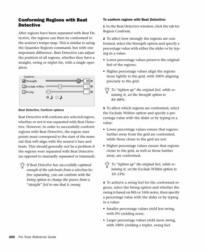
288
Conforming Regions with Beat Detective
After regions have been separated with Beat De-tective, the regions can then be conformed to the session’s tempo map. This is similar to using the Quantize Regions command, but with one important difference. Beat Detective can adjust the position of all regions, whether they have a straight, swing or triplet fee, with a single oper-ation.
Beat Detective will conform any selected region, whether or not it was separated with Beat Detec-tive. However, in order to successfully conform regions with Beat Detective, the region start points must correspond to the start of the mate-rial that will align with the session’s bars and beats. This should generally not be a problem if the regions were separated with Beat Detective (as opposed to manually separated or trimmed).
Beat Detective, Conform options
If Beat Detective has successfully captured enough of the sub-beats from a selection be-fore separating, you can conform with the Swing option to change the groove from a “straight” feel to one that is swung.
Pro Tools Reference Guide
To conform regions with Beat Detective:
1 In the Beat Detective window, click the tab for Region Conform.
2 To affect how strongly the regions are con-formed, select the Strength option and specify a percentage value with either the slider or by typ-ing in a value:
• Lower percentage values preserve the original feel of the regions.
• Higher percentage values align the regions more tightly to the grid, with 100% aligning precisely to the grid.
3 To affect which regions are conformed, select the Exclude Within option and specify a per-centage value with the slider or by typing in a value:
• Lower percentage values ensure that regions further away from the grid are conformed, while those closer to the grid are not.
• Higher percentage values ensure that regions closer to the grid, as well as those further away, are conformed.
4 To achieve a swing feel for the conformed re-gions, select the Swing option and whether the swing is based on 8th or 16th notes, then specify a percentage value with the slider or by typing in a value:
• Smaller percentage values yield less swing, with 0% yielding none.
• Larger percentage values yield more swing, with 100% yielding a triplet, swing feel.
To “tighten up” the original feel, while re-taining it, set the Strength option to 85–88%.
To “tighten up” the original feel, while re-taining it, set the Exclude Within option to 10–15%.
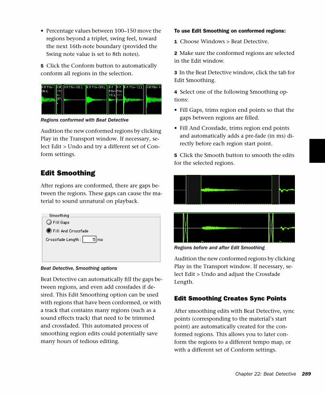
• Percentage values between 100–150 move the regions beyond a triplet, swing feel, toward the next 16th-note boundary (provided the Swing note value is set to 8th notes).
5 Click the Conform button to automatically conform all regions in the selection.
Audition the new conformed regions by clicking Play in the Transport window. If necessary, se-lect Edit > Undo and try a different set of Con-form settings.
Edit Smoothing
After regions are conformed, there are gaps be-tween the regions. These gaps can cause the ma-terial to sound unnatural on playback.
Beat Detective can automatically fill the gaps be-tween regions, and even add crossfades if de-sired. This Edit Smoothing option can be used with regions that have been conformed, or with a track that contains many regions (such as a sound effects track) that need to be trimmed and crossfaded. This automated process of smoothing region edits could potentially save many hours of tedious editing.
Regions conformed with Beat Detective
Beat Detective, Smoothing options
To use Edit Smoothing on conformed regions:
1 Choose Windows > Beat Detective.
2 Make sure the conformed regions are selected in the Edit window.
3 In the Beat Detective window, click the tab for Edit Smoothing.
4 Select one of the following Smoothing op-tions:
• Fill Gaps, trims region end points so that the gaps between regions are filled.
• Fill And Crossfade, trims region end points and automatically adds a pre-fade (in ms) di-rectly before each region start point.
5 Click the Smooth button to smooth the edits for the selected regions.
Audition the new conformed regions by clicking Play in the Transport window. If necessary, se-lect Edit > Undo and adjust the Crossfade Length.
Edit Smoothing Creates Sync Points
After smoothing edits with Beat Detective, sync points (corresponding to the material’s start point) are automatically created for the con-formed regions. This allows you to later con-form the regions to a different tempo map, or with a different set of Conform settings.
Regions before and after Edit Smoothing
Chapter 22: Beat Detective 289
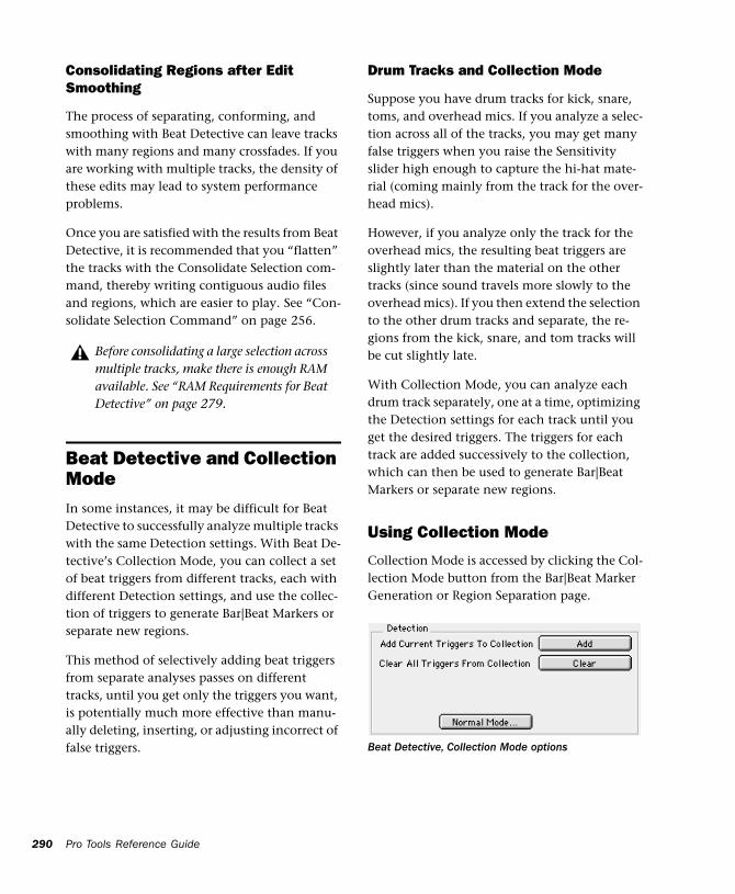
290
Consolidating Regions after Edit Smoothing
The process of separating, conforming, and smoothing with Beat Detective can leave tracks with many regions and many crossfades. If you are working with multiple tracks, the density of these edits may lead to system performance problems.
Once you are satisfied with the results from Beat Detective, it is recommended that you “flatten” the tracks with the Consolidate Selection com-mand, thereby writing contiguous audio files and regions, which are easier to play. See “Con-solidate Selection Command” on page 256.
Beat Detective and Collection ModeIn some instances, it may be difficult for Beat Detective to successfully analyze multiple tracks with the same Detection settings. With Beat De-tective’s Collection Mode, you can collect a set of beat triggers from different tracks, each with different Detection settings, and use the collec-tion of triggers to generate Bar|Beat Markers or separate new regions.
This method of selectively adding beat triggers from separate analyses passes on different tracks, until you get only the triggers you want, is potentially much more effective than manu-ally deleting, inserting, or adjusting incorrect of false triggers.
Before consolidating a large selection across multiple tracks, make there is enough RAM available. See “RAM Requirements for Beat Detective” on page 279.
Pro Tools Reference Guide
Drum Tracks and Collection Mode
Suppose you have drum tracks for kick, snare, toms, and overhead mics. If you analyze a selec-tion across all of the tracks, you may get many false triggers when you raise the Sensitivity slider high enough to capture the hi-hat mate-rial (coming mainly from the track for the over-head mics).
However, if you analyze only the track for the overhead mics, the resulting beat triggers are slightly later than the material on the other tracks (since sound travels more slowly to the overhead mics). If you then extend the selection to the other drum tracks and separate, the re-gions from the kick, snare, and tom tracks will be cut slightly late.
With Collection Mode, you can analyze each drum track separately, one at a time, optimizing the Detection settings for each track until you get the desired triggers. The triggers for each track are added successively to the collection, which can then be used to generate Bar|Beat Markers or separate new regions.
Using Collection Mode
Collection Mode is accessed by clicking the Col-lection Mode button from the Bar|Beat Marker Generation or Region Separation page.
Beat Detective, Collection Mode options
To use Beat Detective’s Collection Mode:
1 Define the selection for the first audio track you want to analyze (see “Defining the Selection for Beat Detective” on page 282).
2 Adjust the Detection parameters so the de-sired beat triggers appear (see “Detecting Tran-sients with Beat Detective” on page 283).
3 Click the Collection Mode button.
4 In the Collection mode sub-pane, click Add to add the current beat triggers to the collection.
5 Click the Normal Mode button and repeat the previous steps for each track you want to ana-lyze. Make sure to keep the selection range the constant for each track. Each new set of triggers added to the collection appears in a different color.
If successive triggers in the collection are located closely together (because of mic leakage), Beat Detective keeps only the earlier triggers.
6 Once the desired beat triggers have been added to the collection, you can use them to generate Bar|Beat Markers, or separate new re-gions. This must be done from the Collection Mode sub-pane (when the triggers are displayed in multi-colors).
To separate regions across multiple tracks, make sure to extend the selection to any ad-ditional tracks before separating.
the Beat Triggers stored in the Collection Mode are saved with sessions. Therefore, when you later open a session, the previous collection material is still there (until you clear it).
Chapter 22: Beat Detective 291

292
Pro Tools Reference Guide
Part V: MIDI Editing
293

294
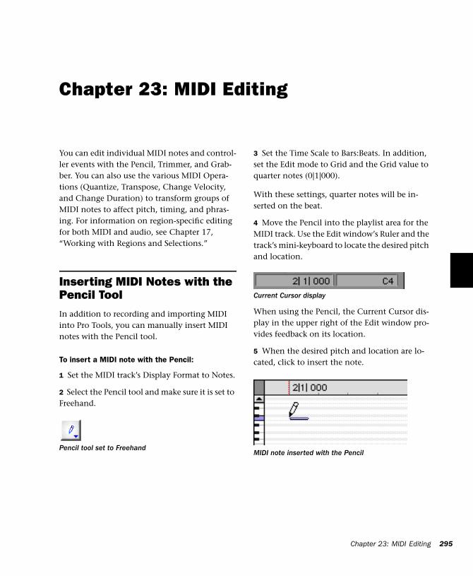
Chapter 23: MIDI Editing
You can edit individual MIDI notes and control-ler events with the Pencil, Trimmer, and Grab-ber. You can also use the various MIDI Opera-tions (Quantize, Transpose, Change Velocity, and Change Duration) to transform groups of MIDI notes to affect pitch, timing, and phras-ing. For information on region-specific editing for both MIDI and audio, see Chapter 17, “Working with Regions and Selections.”
Inserting MIDI Notes with the Pencil ToolIn addition to recording and importing MIDI into Pro Tools, you can manually insert MIDI notes with the Pencil tool.
To insert a MIDI note with the Pencil:
1 Set the MIDI track’s Display Format to Notes.
2 Select the Pencil tool and make sure it is set to Freehand.
Pencil tool set to Freehand
3 Set the Time Scale to Bars:Beats. In addition, set the Edit mode to Grid and the Grid value to quarter notes (0|1|000).
With these settings, quarter notes will be in-serted on the beat.
4 Move the Pencil into the playlist area for the MIDI track. Use the Edit window’s Ruler and the track’s mini-keyboard to locate the desired pitch and location.
When using the Pencil, the Current Cursor dis-play in the upper right of the Edit window pro-vides feedback on its location.
5 When the desired pitch and location are lo-cated, click to insert the note.
Current Cursor display
MIDI note inserted with the Pencil
Chapter 23: MIDI Editing 295
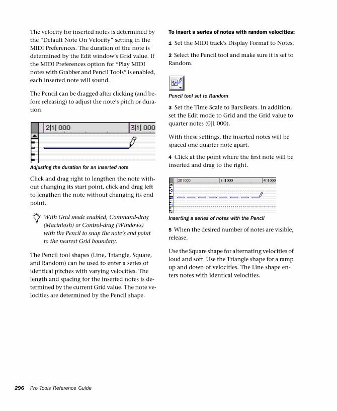
296
The velocity for inserted notes is determined by the “Default Note On Velocity” setting in the MIDI Preferences. The duration of the note is determined by the Edit window’s Grid value. If the MIDI Preferences option for “Play MIDI notes with Grabber and Pencil Tools” is enabled, each inserted note will sound.
The Pencil can be dragged after clicking (and be-fore releasing) to adjust the note’s pitch or dura-tion.
Click and drag right to lengthen the note with-out changing its start point, click and drag left to lengthen the note without changing its end point.
The Pencil tool shapes (Line, Triangle, Square, and Random) can be used to enter a series of identical pitches with varying velocities. The length and spacing for the inserted notes is de-termined by the current Grid value. The note ve-locities are determined by the Pencil shape.
Adjusting the duration for an inserted note
With Grid mode enabled, Command-drag (Macintosh) or Control-drag (Windows) with the Pencil to snap the note’s end point to the nearest Grid boundary.
Pro Tools Reference Guide
To insert a series of notes with random velocities:
1 Set the MIDI track’s Display Format to Notes.
2 Select the Pencil tool and make sure it is set to Random.
3 Set the Time Scale to Bars:Beats. In addition, set the Edit mode to Grid and the Grid value to quarter notes (0|1|000).
With these settings, the inserted notes will be spaced one quarter note apart.
4 Click at the point where the first note will be inserted and drag to the right.
5 When the desired number of notes are visible, release.
Use the Square shape for alternating velocities of loud and soft. Use the Triangle shape for a ramp up and down of velocities. The Line shape en-ters notes with identical velocities.
Pencil tool set to Random
Inserting a series of notes with the Pencil
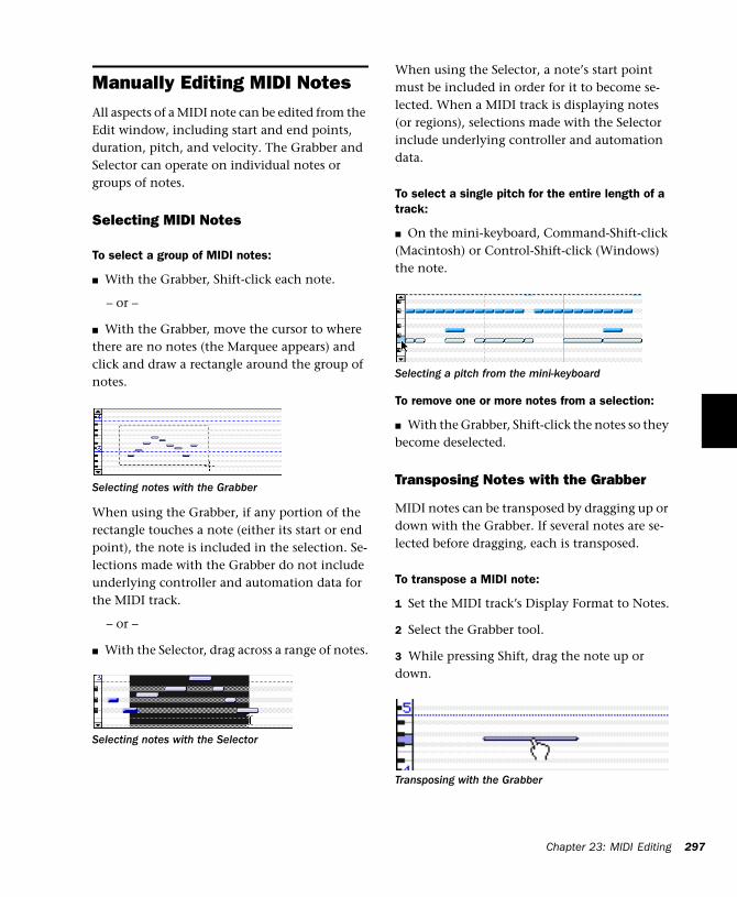
Manually Editing MIDI NotesAll aspects of a MIDI note can be edited from the Edit window, including start and end points, duration, pitch, and velocity. The Grabber and Selector can operate on individual notes or groups of notes.
Selecting MIDI Notes
To select a group of MIDI notes:
■ With the Grabber, Shift-click each note.
– or –
■ With the Grabber, move the cursor to where there are no notes (the Marquee appears) and click and draw a rectangle around the group of notes.
When using the Grabber, if any portion of the rectangle touches a note (either its start or end point), the note is included in the selection. Se-lections made with the Grabber do not include underlying controller and automation data for the MIDI track.
– or –
■ With the Selector, drag across a range of notes.
Selecting notes with the Grabber
Selecting notes with the Selector
When using the Selector, a note’s start point must be included in order for it to become se-lected. When a MIDI track is displaying notes (or regions), selections made with the Selector include underlying controller and automation data.
To select a single pitch for the entire length of a track:
■ On the mini-keyboard, Command-Shift-click (Macintosh) or Control-Shift-click (Windows) the note.
To remove one or more notes from a selection:
■ With the Grabber, Shift-click the notes so they become deselected.
Transposing Notes with the Grabber
MIDI notes can be transposed by dragging up or down with the Grabber. If several notes are se-lected before dragging, each is transposed.
To transpose a MIDI note:
1 Set the MIDI track’s Display Format to Notes.
2 Select the Grabber tool.
3 While pressing Shift, drag the note up or down.
Selecting a pitch from the mini-keyboard
Transposing with the Grabber
Chapter 23: MIDI Editing 297
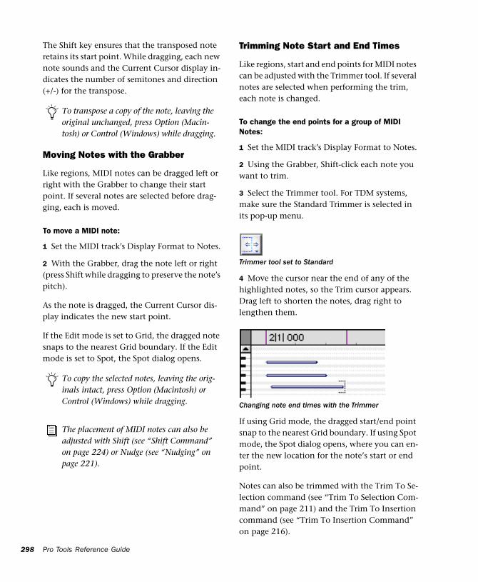
298
The Shift key ensures that the transposed note retains its start point. While dragging, each new note sounds and the Current Cursor display in-dicates the number of semitones and direction (+/-) for the transpose.
Moving Notes with the Grabber
Like regions, MIDI notes can be dragged left or right with the Grabber to change their start point. If several notes are selected before drag-ging, each is moved.
To move a MIDI note:
1 Set the MIDI track’s Display Format to Notes.
2 With the Grabber, drag the note left or right (press Shift while dragging to preserve the note’s pitch).
As the note is dragged, the Current Cursor dis-play indicates the new start point.
If the Edit mode is set to Grid, the dragged note snaps to the nearest Grid boundary. If the Edit mode is set to Spot, the Spot dialog opens.
To transpose a copy of the note, leaving the original unchanged, press Option (Macin-tosh) or Control (Windows) while dragging.
To copy the selected notes, leaving the orig-inals intact, press Option (Macintosh) or Control (Windows) while dragging.
The placement of MIDI notes can also be adjusted with Shift (see “Shift Command” on page 224) or Nudge (see “Nudging” on page 221).
Pro Tools Reference Guide
Trimming Note Start and End Times
Like regions, start and end points for MIDI notes can be adjusted with the Trimmer tool. If several notes are selected when performing the trim, each note is changed.
To change the end points for a group of MIDI Notes:
1 Set the MIDI track’s Display Format to Notes.
2 Using the Grabber, Shift-click each note you want to trim.
3 Select the Trimmer tool. For TDM systems, make sure the Standard Trimmer is selected in its pop-up menu.
4 Move the cursor near the end of any of the highlighted notes, so the Trim cursor appears. Drag left to shorten the notes, drag right to lengthen them.
If using Grid mode, the dragged start/end point snap to the nearest Grid boundary. If using Spot mode, the Spot dialog opens, where you can en-ter the new location for the note’s start or end point.
Notes can also be trimmed with the Trim To Se-lection command (see “Trim To Selection Com-mand” on page 211) and the Trim To Insertion command (see “Trim To Insertion Command” on page 216).
Trimmer tool set to Standard
Changing note end times with the Trimmer
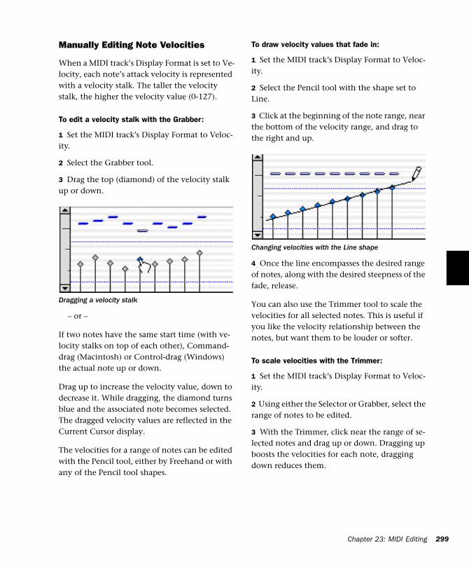
Manually Editing Note Velocities
When a MIDI track’s Display Format is set to Ve-locity, each note’s attack velocity is represented with a velocity stalk. The taller the velocity stalk, the higher the velocity value (0-127).
To edit a velocity stalk with the Grabber:
1 Set the MIDI track’s Display Format to Veloc-ity.
2 Select the Grabber tool.
3 Drag the top (diamond) of the velocity stalk up or down.
– or –
If two notes have the same start time (with ve-locity stalks on top of each other), Command-drag (Macintosh) or Control-drag (Windows) the actual note up or down.
Drag up to increase the velocity value, down to decrease it. While dragging, the diamond turns blue and the associated note becomes selected. The dragged velocity values are reflected in the Current Cursor display.
The velocities for a range of notes can be edited with the Pencil tool, either by Freehand or with any of the Pencil tool shapes.
Dragging a velocity stalk
To draw velocity values that fade in:
1 Set the MIDI track’s Display Format to Veloc-ity.
2 Select the Pencil tool with the shape set to Line.
3 Click at the beginning of the note range, near the bottom of the velocity range, and drag to the right and up.
4 Once the line encompasses the desired range of notes, along with the desired steepness of the fade, release.
You can also use the Trimmer tool to scale the velocities for all selected notes. This is useful if you like the velocity relationship between the notes, but want them to be louder or softer.
To scale velocities with the Trimmer:
1 Set the MIDI track’s Display Format to Veloc-ity.
2 Using either the Selector or Grabber, select the range of notes to be edited.
3 With the Trimmer, click near the range of se-lected notes and drag up or down. Dragging up boosts the velocities for each note, dragging down reduces them.
Changing velocities with the Line shape
Chapter 23: MIDI Editing 299
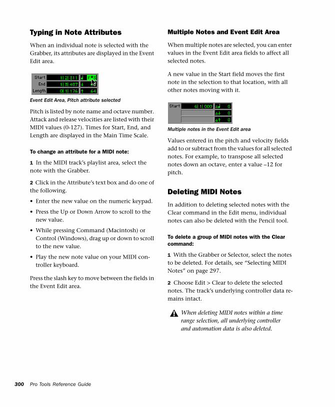
300
Typing in Note Attributes
When an individual note is selected with the Grabber, its attributes are displayed in the Event Edit area.
Pitch is listed by note name and octave number. Attack and release velocities are listed with their MIDI values (0-127). Times for Start, End, and Length are displayed in the Main Time Scale.
To change an attribute for a MIDI note:
1 In the MIDI track’s playlist area, select the note with the Grabber.
2 Click in the Attribute’s text box and do one of the following.
• Enter the new value on the numeric keypad.
• Press the Up or Down Arrow to scroll to the new value.
• While pressing Command (Macintosh) or Control (Windows), drag up or down to scroll to the new value.
• Play the new note value on your MIDI con-troller keyboard.
Press the slash key to move between the fields in the Event Edit area.
Event Edit Area, Pitch attribute selected
Pro Tools Reference Guide
Multiple Notes and Event Edit Area
When multiple notes are selected, you can enter values in the Event Edit area fields to affect all selected notes.
A new value in the Start field moves the first note in the selection to that location, with all other notes moving with it.
Values entered in the pitch and velocity fields add to or subtract from the values for all selected notes. For example, to transpose all selected notes down an octave, enter a value –12 for pitch.
Deleting MIDI Notes
In addition to deleting selected notes with the Clear command in the Edit menu, individual notes can also be deleted with the Pencil tool.
To delete a group of MIDI notes with the Clear command:
1 With the Grabber or Selector, select the notes to be deleted. For details, see “Selecting MIDI Notes” on page 297.
2 Choose Edit > Clear to delete the selected notes. The track’s underlying controller data re-mains intact.
Multiple notes in the Event Edit area
When deleting MIDI notes within a time range selection, all underlying controller and automation data is also deleted.
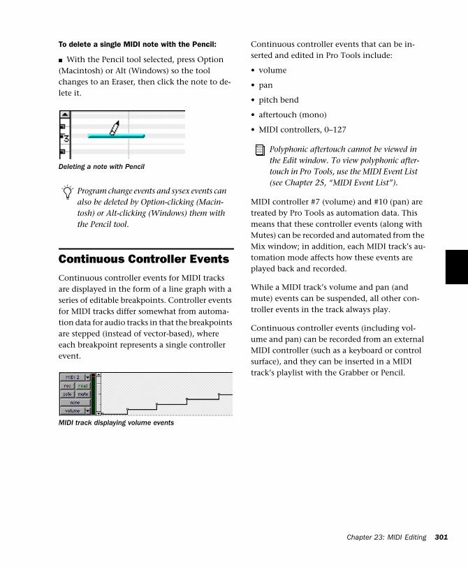
To delete a single MIDI note with the Pencil:
■ With the Pencil tool selected, press Option (Macintosh) or Alt (Windows) so the tool changes to an Eraser, then click the note to de-lete it.
Continuous Controller EventsContinuous controller events for MIDI tracks are displayed in the form of a line graph with a series of editable breakpoints. Controller events for MIDI tracks differ somewhat from automa-tion data for audio tracks in that the breakpoints are stepped (instead of vector-based), where each breakpoint represents a single controller event.
Deleting a note with Pencil
Program change events and sysex events can also be deleted by Option-clicking (Macin-tosh) or Alt-clicking (Windows) them with the Pencil tool.
MIDI track displaying volume events
Continuous controller events that can be in-serted and edited in Pro Tools include:
• volume
• pan
• pitch bend
• aftertouch (mono)
• MIDI controllers, 0–127
MIDI controller #7 (volume) and #10 (pan) are treated by Pro Tools as automation data. This means that these controller events (along with Mutes) can be recorded and automated from the Mix window; in addition, each MIDI track’s au-tomation mode affects how these events are played back and recorded.
While a MIDI track’s volume and pan (and mute) events can be suspended, all other con-troller events in the track always play.
Continuous controller events (including vol-ume and pan) can be recorded from an external MIDI controller (such as a keyboard or control surface), and they can be inserted in a MIDI track’s playlist with the Grabber or Pencil.
Polyphonic aftertouch cannot be viewed in the Edit window. To view polyphonic after-touch in Pro Tools, use the MIDI Event List (see Chapter 25, “MIDI Event List”).
Chapter 23: MIDI Editing 301
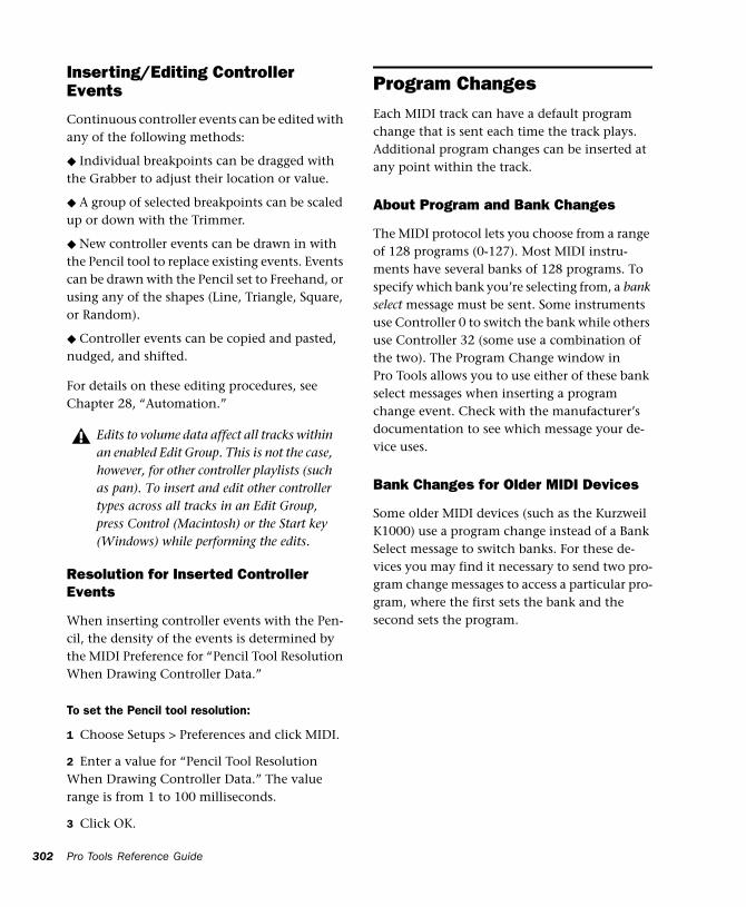
302
Inserting/Editing Controller Events
Continuous controller events can be edited with any of the following methods:
◆ Individual breakpoints can be dragged with the Grabber to adjust their location or value.
◆ A group of selected breakpoints can be scaled up or down with the Trimmer.
◆ New controller events can be drawn in with the Pencil tool to replace existing events. Events can be drawn with the Pencil set to Freehand, or using any of the shapes (Line, Triangle, Square, or Random).
◆ Controller events can be copied and pasted, nudged, and shifted.
For details on these editing procedures, see Chapter 28, “Automation.”
Resolution for Inserted Controller Events
When inserting controller events with the Pen-cil, the density of the events is determined by the MIDI Preference for “Pencil Tool Resolution When Drawing Controller Data.”
To set the Pencil tool resolution:
1 Choose Setups > Preferences and click MIDI.
2 Enter a value for “Pencil Tool Resolution When Drawing Controller Data.” The value range is from 1 to 100 milliseconds.
3 Click OK.
Edits to volume data affect all tracks within an enabled Edit Group. This is not the case, however, for other controller playlists (such as pan). To insert and edit other controller types across all tracks in an Edit Group, press Control (Macintosh) or the Start key (Windows) while performing the edits.
Pro Tools Reference Guide
Program ChangesEach MIDI track can have a default program change that is sent each time the track plays. Additional program changes can be inserted at any point within the track.
About Program and Bank Changes
The MIDI protocol lets you choose from a range of 128 programs (0-127). Most MIDI instru-ments have several banks of 128 programs. To specify which bank you’re selecting from, a bank select message must be sent. Some instruments use Controller 0 to switch the bank while others use Controller 32 (some use a combination of the two). The Program Change window in Pro Tools allows you to use either of these bank select messages when inserting a program change event. Check with the manufacturer’s documentation to see which message your de-vice uses.
Bank Changes for Older MIDI Devices
Some older MIDI devices (such as the Kurzweil K1000) use a program change instead of a Bank Select message to switch banks. For these de-vices you may find it necessary to send two pro-gram change messages to access a particular pro-gram, where the first sets the bank and the second sets the program.
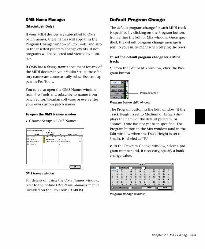
OMS Name Manager
(Macintosh Only)
If your MIDI devices are subscribed to OMS patch names, these names will appear in the Program Change window in Pro Tools, and also in the inserted program change events. If not, programs will be selected and viewed by num-ber.
If OMS has a factory names document for any of the MIDI devices in your Studio Setup, these fac-tory names are automatically subscribed and ap-pear in Pro Tools.
You can also open the OMS Names window from Pro Tools and subscribe to names from patch editor/librarian software, or even enter your own custom patch names.
To open the OMS Names window:
■ Choose Setups > OMS Names.
For details on using the OMS Names window, refer to the online OMS Name Manager manual included on the Pro Tools CD-ROM.
OMS Names window
Default Program Change
The default program change for each MIDI track is specified by clicking on the Program button, from either the Edit or Mix window. Once spec-ified, the default program change message is sent to your instrument when playing the track.
To set the default program change for a MIDI track:
1 From the Edit or Mix window, click the Pro-gram button.
The Program button in the Edit window (if the Track Height is set to Medium or Larger) dis-plays the name of the default program, or “none” if one has not yet been specified. The Program button in the Mix window (and in the Edit window when the Track Height is set to Small), is labeled as “P.”
2 In the Program Change window, select a pro-gram number and, if necessary, specify a bank change value.
Program button, Edit window
Program Change window
Program button
Chapter 23: MIDI Editing 303
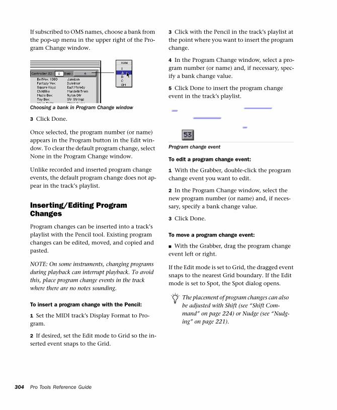
304
If subscribed to OMS names, choose a bank from the pop-up menu in the upper right of the Pro-gram Change window.
3 Click Done.
Once selected, the program number (or name) appears in the Program button in the Edit win-dow. To clear the default program change, select None in the Program Change window.
Unlike recorded and inserted program change events, the default program change does not ap-pear in the track’s playlist.
Inserting/Editing Program Changes
Program changes can be inserted into a track’s playlist with the Pencil tool. Existing program changes can be edited, moved, and copied and pasted.
NOTE: On some instruments, changing programs during playback can interrupt playback. To avoid this, place program change events in the track where there are no notes sounding.
To insert a program change with the Pencil:
1 Set the MIDI track’s Display Format to Pro-gram.
2 If desired, set the Edit mode to Grid so the in-serted event snaps to the Grid.
Choosing a bank in Program Change window
Pro Tools Reference Guide
3 Click with the Pencil in the track’s playlist at the point where you want to insert the program change.
4 In the Program Change window, select a pro-gram number (or name) and, if necessary, spec-ify a bank change value.
5 Click Done to insert the program change event in the track’s playlist.
To edit a program change event:
1 With the Grabber, double-click the program change event you want to edit.
2 In the Program Change window, select the new program number (or name) and, if neces-sary, specify a bank change value.
3 Click Done.
To move a program change event:
■ With the Grabber, drag the program change event left or right.
If the Edit mode is set to Grid, the dragged event snaps to the nearest Grid boundary. If the Edit mode is set to Spot, the Spot dialog opens.
Program change event
The placement of program changes can also be adjusted with Shift (see “Shift Com-mand” on page 224) or Nudge (see “Nudg-ing” on page 221).
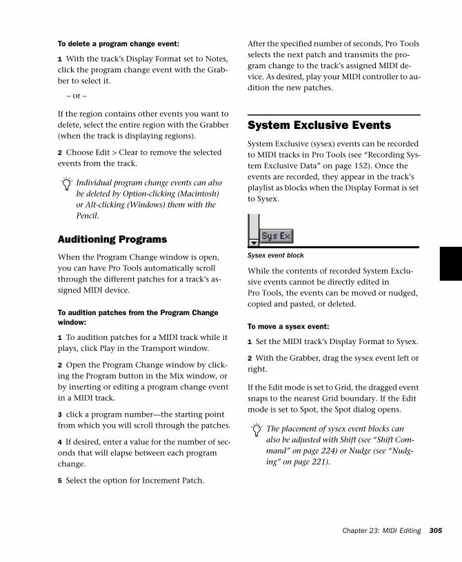
To delete a program change event:
1 With the track’s Display Format set to Notes, click the program change event with the Grab-ber to select it.
– or –
If the region contains other events you want to delete, select the entire region with the Grabber (when the track is displaying regions).
2 Choose Edit > Clear to remove the selected events from the track.
Auditioning Programs
When the Program Change window is open, you can have Pro Tools automatically scroll through the different patches for a track’s as-signed MIDI device.
To audition patches from the Program Change window:
1 To audition patches for a MIDI track while it plays, click Play in the Transport window.
2 Open the Program Change window by click-ing the Program button in the Mix window, or by inserting or editing a program change event in a MIDI track.
3 click a program number—the starting point from which you will scroll through the patches.
4 If desired, enter a value for the number of sec-onds that will elapse between each program change.
5 Select the option for Increment Patch.
Individual program change events can also be deleted by Option-clicking (Macintosh) or Alt-clicking (Windows) them with the Pencil.
After the specified number of seconds, Pro Tools selects the next patch and transmits the pro-gram change to the track’s assigned MIDI de-vice. As desired, play your MIDI controller to au-dition the new patches.
System Exclusive EventsSystem Exclusive (sysex) events can be recorded to MIDI tracks in Pro Tools (see “Recording Sys-tem Exclusive Data” on page 152). Once the events are recorded, they appear in the track’s playlist as blocks when the Display Format is set to Sysex.
While the contents of recorded System Exclu-sive events cannot be directly edited in Pro Tools, the events can be moved or nudged, copied and pasted, or deleted.
To move a sysex event:
1 Set the MIDI track’s Display Format to Sysex.
2 With the Grabber, drag the sysex event left or right.
If the Edit mode is set to Grid, the dragged event snaps to the nearest Grid boundary. If the Edit mode is set to Spot, the Spot dialog opens.
Sysex event block
The placement of sysex event blocks can also be adjusted with Shift (see “Shift Com-mand” on page 224) or Nudge (see “Nudg-ing” on page 221).
Chapter 23: MIDI Editing 305
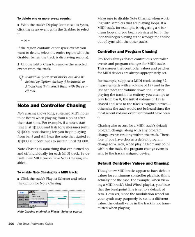
306
To delete one or more sysex events:
1 With the track’s Display Format set to Sysex, click the sysex event with the Grabber to select it.
– or –
If the region contains other sysex events you want to delete, select the entire region with the Grabber (when the track is displaying regions).
2 Choose Edit > Clear to remove the selected events from the track.
Note and Controller ChasingNote chasing allows long, sustained MIDI notes to be heard when playing from a point after their start time. For example, if a note’s start time is at 1|1|000 and lasts for 8 measures (until 9|1|000), note chasing lets you begin playing from bar 5 and still hear the note that started at 1|1|000 as it continues to sustain until 9|1|000.
Note Chasing is something that can turned on and off individually for each MIDI track. By de-fault, new MIDI tracks have Note Chasing en-abled.
To enable Note Chasing for a MIDI track:
■ Click the track’s Playlist Selector and select the option for Note Chasing.
Individual sysex event blocks can also be deleted by Option-clicking (Macintosh) or Alt-clicking (Windows) them with the Pen-cil tool.
Note Chasing enabled in Playlist Selector pop-up
Pro Tools Reference Guide
Make sure to disable Note Chasing when work-ing with samplers that are playing loops. If a MIDI track, for example, is triggering a 4-bar drum loop and you begin playing at bar 3, the loop will begin playing at the wrong time and be out of sync with the other tracks.
Controller and Program Chasing
Pro Tools always chases continuous controller events and program changes for MIDI tracks. This ensures that controller values and patches for MIDI devices are always appropriately set.
For example, suppose a MIDI track lasting 32 measures starts with a volume of 127 and in the last bar fades the volume down to 0. If after playing the track in its entirety you attempt to play from bar 8, the initial volume of 127 is chased and sent to the track’s assigned device—otherwise the track would not be heard since the most recent volume event sent would have been 0.
Chasing also occurs for a MIDI track’s default program change, along with any program change events residing within the track. There-fore, if you have chosen a default program change for a track, when playing from any point within the track, the program change event is sent to the track’s assigned device.
Default Controller Values and Chasing
Though new MIDI tracks appear to have default values for continuous controller playlists, this is actually not the case. For example, when view-ing a MIDI track’s Mod Wheel playlist, you’ll see that the breakpoint line is set to a default of zero. However, since the modulation wheel on your synth may purposely be set to a different value, the default value in the track is not trans-mitted when playing.
This can cause some confusion, however, if you insert a fade (for example, from 0–90) in the Mod Wheel playlist towards the end of the track. If you then play from the beginning of the track, or from anywhere before the fade, the Mod Wheel value on your synth will be at 90 until the beginning of the fade data is reached—which is likely not what you want.
To ensure that the default controller value for a playlist is sent (and chased), click the initial breakpoint at the beginning of the track, move it slightly, and set it back to the default value.
Offsetting MIDI TracksPro Tools can offset MIDI tracks globally or indi-vidually.
Global MIDI Playback Offset
Pro Tools offers a MIDI offset preference that al-lows MIDI tracks to play back earlier or later (than audio tracks) by a specified number of samples. The offset affects playback only and does not alter in any way how MIDI data is dis-played in the Edit window.
This capability is provided in large part to com-pensate for the audio monitoring latency in Pro Tools LE. If you are monitoring the output of your MIDI devices with an external mixer or sound system (or headphones), there is no la-tency. If, however, you are monitoring the out-put of your MIDI devices through a Digi 001 (or Audiomedia III), your MIDI tracks will appear to play slightly later than your audio tracks. The larger the setting for the Hardware Buffer Size (128, 256, 512, or 1024 samples), the larger the latency.
By configuring the Global MIDI Playback Offset, you can get your MIDI tracks to play back slightly earlier (by a specified number of sam-ples), thereby compensating for the latency in monitoring audio within Pro Tools LE.
To configure the Global MIDI Playback Offset:
1 Choose Setups > Preferences and click MIDI.
2 For the “Global MIDI Playback Offset” option, enter the number of samples (–10,000 to 10,000) for the offset. A negative value causes the MIDI tracks to play back earlier than the au-dio tracks, a positive value causes the MIDI tracks to play back later.
To allow for monitoring latency in Pro Tools LE, set the offset to a value that is roughly equiva-lent to the Hardware Buffer Size.
3 Click Done.
Individual MIDI Track Offsets
You can offset individual MIDI track offsets in Pro Tools to compensate for delays in MIDI de-vices (the time it takes to trigger events on a sampler or synth).
For example, if you have some kick drums that are being played by an audio track in Pro Tools and want them to be perfectly “in sync” with kick drums that are being played by a MIDI de-vice, you may need to use a MIDI offset. In this example, it will usually take at least 5 ms to trig-ger the MIDI notes, and it could take even longer, depending on the MIDI device.
The Global MIDI Playback Offset can also be set from the MIDI Track Offsets window.
Chapter 23: MIDI Editing 307
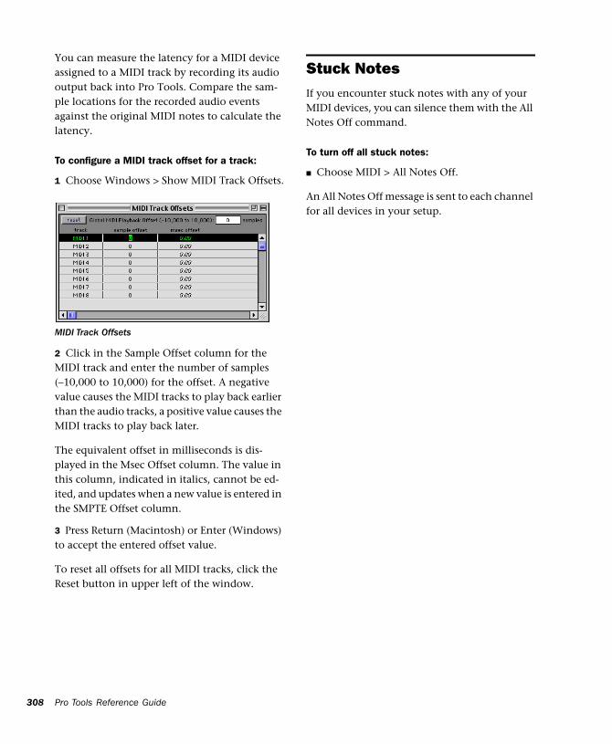
308
You can measure the latency for a MIDI device assigned to a MIDI track by recording its audio output back into Pro Tools. Compare the sam-ple locations for the recorded audio events against the original MIDI notes to calculate the latency.
To configure a MIDI track offset for a track:
1 Choose Windows > Show MIDI Track Offsets.
2 Click in the Sample Offset column for the MIDI track and enter the number of samples (–10,000 to 10,000) for the offset. A negative value causes the MIDI tracks to play back earlier than the audio tracks, a positive value causes the MIDI tracks to play back later.
The equivalent offset in milliseconds is dis-played in the Msec Offset column. The value in this column, indicated in italics, cannot be ed-ited, and updates when a new value is entered in the SMPTE Offset column.
3 Press Return (Macintosh) or Enter (Windows) to accept the entered offset value.
To reset all offsets for all MIDI tracks, click the Reset button in upper left of the window.
MIDI Track Offsets
Pro Tools Reference Guide
Stuck NotesIf you encounter stuck notes with any of your MIDI devices, you can silence them with the All Notes Off command.
To turn off all stuck notes:
■ Choose MIDI > All Notes Off.
An All Notes Off message is sent to each channel for all devices in your setup.
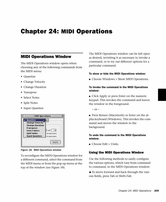
Chapter 24: MIDI Operations
MIDI Operations WindowThe MIDI Operations window opens when choosing any of the following commands from the MIDI menu:
• Quantize
• Change Velocity
• Change Duration
• Transpose
• Select Notes
• Split Notes
• Input Quantize
To reconfigure the MIDI Operations window for a different command, select the command from the MIDI menu or from the pop-up menu at the top of the window (see Figure 18).
Figure 18. MIDI Operations window
The MIDI Operations window can be left open as desired, revisiting it as necessary to invoke a command, or to try out different options for a particular command.
To show or hide the MIDI Operations window:
■ Choose Windows > Show MIDI Operations.
To invoke the command in the MIDI Operations window:
■ Click Apply or press Enter on the numeric keypad. This invokes the command and leaves the window in the foreground.
– or –
■ Press Return (Macintosh) or Enter on the al-pha keyboard (Windows). This invokes the com-mand and moves the window to the background.
To undo the command in the MIDI Operations window:
■ Choose Edit > Undo.
Using the MIDI Operations Window
Use the following methods to easily configure the various options, which vary from command to command, in the MIDI Operations window:
◆ To move forward and back through the vari-ous fields, press Tab or Shift+Tab.
Chapter 24: MIDI Operations 309
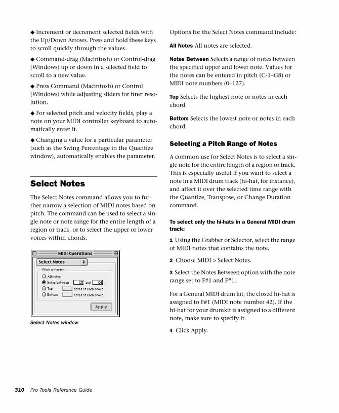
310
◆ Increment or decrement selected fields with the Up/Down Arrows. Press and hold these keys to scroll quickly through the values.
◆ Command-drag (Macintosh) or Control-drag (Windows) up or down in a selected field to scroll to a new value.
◆ Press Command (Macintosh) or Control (Windows) while adjusting sliders for finer reso-lution.
◆ For selected pitch and velocity fields, play a note on your MIDI controller keyboard to auto-matically enter it.
◆ Changing a value for a particular parameter (such as the Swing Percentage in the Quantize window), automatically enables the parameter.
Select NotesThe Select Notes command allows you to fur-ther narrow a selection of MIDI notes based on pitch. The command can be used to select a sin-gle note or note range for the entire length of a region or track, or to select the upper or lower voices within chords.
Select Notes window
Pro Tools Reference Guide
Options for the Select Notes command include:
All Notes All notes are selected.
Notes Between Selects a range of notes between the specified upper and lower note. Values for the notes can be entered in pitch (C-1–G8) or MIDI note numbers (0–127).
Top Selects the highest note or notes in each chord.
Bottom Selects the lowest note or notes in each chord.
Selecting a Pitch Range of Notes
A common use for Select Notes is to select a sin-gle note for the entire length of a region or track. This is especially useful if you want to select a note in a MIDI drum track (hi-hat, for instance), and affect it over the selected time range with the Quantize, Transpose, or Change Duration command.
To select only the hi-hats in a General MIDI drum track:
1 Using the Grabber or Selector, select the range of MIDI notes that contains the note.
2 Choose MIDI > Select Notes.
3 Select the Notes Between option with the note range set to F#1 and F#1.
For a General MIDI drum kit, the closed hi-hat is assigned to F#1 (MIDI note number 42). If the hi-hat for your drumkit is assigned to a different note, make sure to specify it.
4 Click Apply.
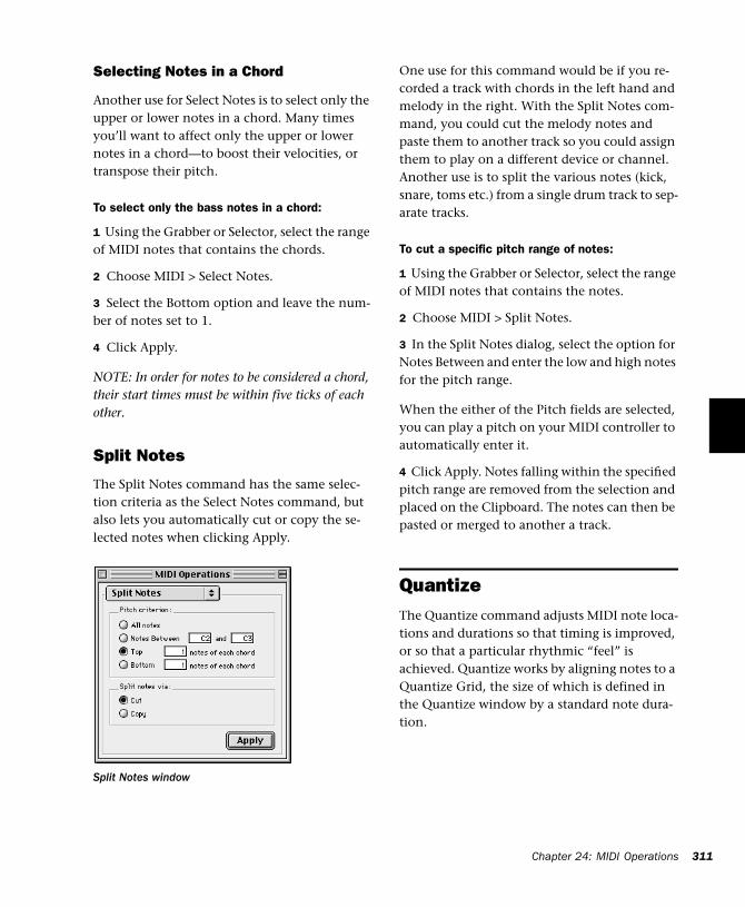
Selecting Notes in a Chord
Another use for Select Notes is to select only the upper or lower notes in a chord. Many times you’ll want to affect only the upper or lower notes in a chord—to boost their velocities, or transpose their pitch.
To select only the bass notes in a chord:
1 Using the Grabber or Selector, select the range of MIDI notes that contains the chords.
2 Choose MIDI > Select Notes.
3 Select the Bottom option and leave the num-ber of notes set to 1.
4 Click Apply.
NOTE: In order for notes to be considered a chord, their start times must be within five ticks of each other.
Split Notes
The Split Notes command has the same selec-tion criteria as the Select Notes command, but also lets you automatically cut or copy the se-lected notes when clicking Apply.
Split Notes window
One use for this command would be if you re-corded a track with chords in the left hand and melody in the right. With the Split Notes com-mand, you could cut the melody notes and paste them to another track so you could assign them to play on a different device or channel. Another use is to split the various notes (kick, snare, toms etc.) from a single drum track to sep-arate tracks.
To cut a specific pitch range of notes:
1 Using the Grabber or Selector, select the range of MIDI notes that contains the notes.
2 Choose MIDI > Split Notes.
3 In the Split Notes dialog, select the option for Notes Between and enter the low and high notes for the pitch range.
When the either of the Pitch fields are selected, you can play a pitch on your MIDI controller to automatically enter it.
4 Click Apply. Notes falling within the specified pitch range are removed from the selection and placed on the Clipboard. The notes can then be pasted or merged to another a track.
QuantizeThe Quantize command adjusts MIDI note loca-tions and durations so that timing is improved, or so that a particular rhythmic “feel” is achieved. Quantize works by aligning notes to a Quantize Grid, the size of which is defined in the Quantize window by a standard note dura-tion.
Chapter 24: MIDI Operations 311
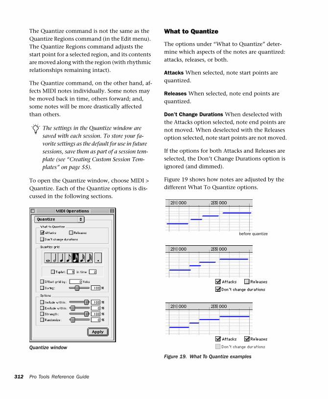
312
The Quantize command is not the same as the Quantize Regions command (in the Edit menu). The Quantize Regions command adjusts the start point for a selected region, and its contents are moved along with the region (with rhythmic relationships remaining intact).
The Quantize command, on the other hand, af-fects MIDI notes individually. Some notes may be moved back in time, others forward; and, some notes will be more drastically affected than others.
To open the Quantize window, choose MIDI > Quantize. Each of the Quantize options is dis-cussed in the following sections.
The settings in the Quantize window are saved with each session. To store your fa-vorite settings as the default for use in future sessions, save them as part of a session tem-plate (see “Creating Custom Session Tem-plates” on page 55).
Quantize window
Pro Tools Reference Guide
What to Quantize
The options under “What to Quantize” deter-mine which aspects of the notes are quantized: attacks, releases, or both.
Attacks When selected, note start points are quantized.
Releases When selected, note end points are quantized.
Don’t Change Durations When deselected with the Attacks option selected, note end points are not moved. When deselected with the Releases option selected, note start points are not moved.
If the options for both Attacks and Releases are selected, the Don’t Change Durations option is ignored (and dimmed).
Figure 19 shows how notes are adjusted by the different What To Quantize options.
Figure 19. What To Quantize examples
before quantize
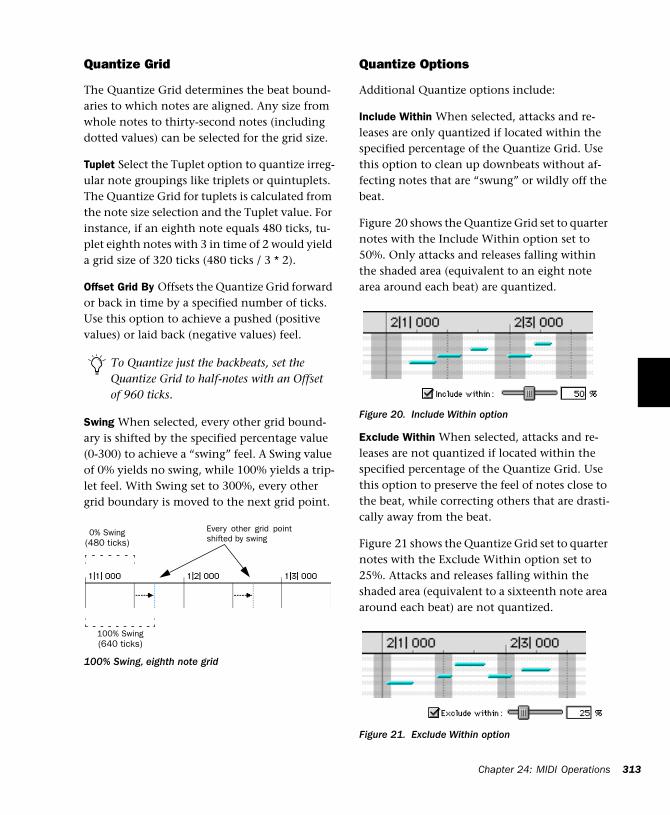
Quantize Grid
The Quantize Grid determines the beat bound-aries to which notes are aligned. Any size from whole notes to thirty-second notes (including dotted values) can be selected for the grid size.
Tuplet Select the Tuplet option to quantize irreg-ular note groupings like triplets or quintuplets. The Quantize Grid for tuplets is calculated from the note size selection and the Tuplet value. For instance, if an eighth note equals 480 ticks, tu-plet eighth notes with 3 in time of 2 would yield a grid size of 320 ticks (480 ticks / 3 * 2).
Offset Grid By Offsets the Quantize Grid forward or back in time by a specified number of ticks. Use this option to achieve a pushed (positive values) or laid back (negative values) feel.
Swing When selected, every other grid bound-ary is shifted by the specified percentage value (0-300) to achieve a “swing” feel. A Swing value of 0% yields no swing, while 100% yields a trip-let feel. With Swing set to 300%, every other grid boundary is moved to the next grid point.
To Quantize just the backbeats, set the Quantize Grid to half-notes with an Offset of 960 ticks.
100% Swing, eighth note grid
Every other grid pointshifted by swing
0% Swing(480 ticks)
100% Swing(640 ticks)
Quantize Options
Additional Quantize options include:
Include Within When selected, attacks and re-leases are only quantized if located within the specified percentage of the Quantize Grid. Use this option to clean up downbeats without af-fecting notes that are “swung” or wildly off the beat.
Figure 20 shows the Quantize Grid set to quarter notes with the Include Within option set to 50%. Only attacks and releases falling within the shaded area (equivalent to an eight note area around each beat) are quantized.
Exclude Within When selected, attacks and re-leases are not quantized if located within the specified percentage of the Quantize Grid. Use this option to preserve the feel of notes close to the beat, while correcting others that are drasti-cally away from the beat.
Figure 21 shows the Quantize Grid set to quarter notes with the Exclude Within option set to 25%. Attacks and releases falling within the shaded area (equivalent to a sixteenth note area around each beat) are not quantized.
Figure 20. Include Within option
Figure 21. Exclude Within option
Chapter 24: MIDI Operations 313
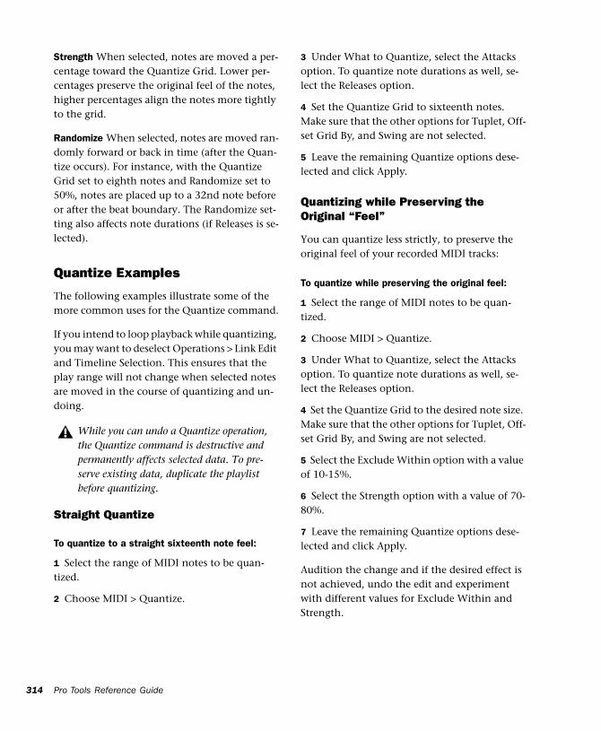
314
Strength When selected, notes are moved a per-centage toward the Quantize Grid. Lower per-centages preserve the original feel of the notes, higher percentages align the notes more tightly to the grid.
Randomize When selected, notes are moved ran-domly forward or back in time (after the Quan-tize occurs). For instance, with the Quantize Grid set to eighth notes and Randomize set to 50%, notes are placed up to a 32nd note before or after the beat boundary. The Randomize set-ting also affects note durations (if Releases is se-lected).
Quantize Examples
The following examples illustrate some of the more common uses for the Quantize command.
If you intend to loop playback while quantizing, you may want to deselect Operations > Link Edit and Timeline Selection. This ensures that the play range will not change when selected notes are moved in the course of quantizing and un-doing.
Straight Quantize
To quantize to a straight sixteenth note feel:
1 Select the range of MIDI notes to be quan-tized.
2 Choose MIDI > Quantize.
While you can undo a Quantize operation, the Quantize command is destructive and permanently affects selected data. To pre-serve existing data, duplicate the playlist before quantizing.
Pro Tools Reference Guide
3 Under What to Quantize, select the Attacks option. To quantize note durations as well, se-lect the Releases option.
4 Set the Quantize Grid to sixteenth notes. Make sure that the other options for Tuplet, Off-set Grid By, and Swing are not selected.
5 Leave the remaining Quantize options dese-lected and click Apply.
Quantizing while Preserving the Original “Feel”
You can quantize less strictly, to preserve the original feel of your recorded MIDI tracks:
To quantize while preserving the original feel:
1 Select the range of MIDI notes to be quan-tized.
2 Choose MIDI > Quantize.
3 Under What to Quantize, select the Attacks option. To quantize note durations as well, se-lect the Releases option.
4 Set the Quantize Grid to the desired note size. Make sure that the other options for Tuplet, Off-set Grid By, and Swing are not selected.
5 Select the Exclude Within option with a value of 10-15%.
6 Select the Strength option with a value of 70-80%.
7 Leave the remaining Quantize options dese-lected and click Apply.
Audition the change and if the desired effect is not achieved, undo the edit and experiment with different values for Exclude Within and Strength.
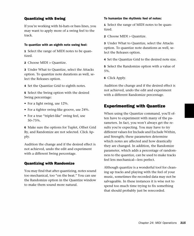
Quantizing with Swing
If you’re working with hi-hats or bass lines, you may want to apply more of a swing feel to the track.
To quantize with an eighth note swing feel:
1 Select the range of MIDI notes to be quan-tized.
2 Choose MIDI > Quantize.
3 Under What to Quantize, select the Attacks option. To quantize note durations as well, se-lect the Releases option.
4 Set the Quantize Grid to eighth notes.
5 Select the Swing option with the desired Swing percentage:
• For a light swing, use 12%.
• For a tighter swing-like groove, use 24%.
• For a true “triplet-like” swing feel, use 50–75%.
6 Make sure the options for Tuplet, Offset Grid By, and Randomize are not selected. Click Ap-ply.
Audition the change and if the desired effect is not achieved, undo the edit and experiment with a different Swing percentage.
Quantizing with Randomize
You may find that after quantizing, notes sound too mechanical, too “on the beat.” You can use the Randomize option in the Quantize window to make them sound more natural.
To humanize the rhythmic feel of notes:
1 Select the range of MIDI notes to be quan-tized.
2 Choose MIDI > Quantize.
3 Under What to Quantize, select the Attacks option. To quantize note durations as well, se-lect the Releases option.
4 Set the Quantize Grid to the desired note size.
5 Select the Randomize option with a value of 5%.
6 Click Apply.
Audition the change and if the desired effect is not achieved, undo the edit and experiment with a different Randomize percentage.
Experimenting with Quantize
When using the Quantize command, you’ll of-ten have to experiment with many of the pa-rameters. In fact, you won’t always get the re-sults you’re expecting. You may have to try different values for Include and Exclude Within, and Strength; these parameters determine which notes are affected and how drastically they are changed. In addition, the Randomize parameter, which adds a percentage of random-ness to the quantize, can be used to make tracks feel less mechanical—less perfect.
Although quantize is a wonderful tool for clean-ing up tracks and playing with the feel of your music, sometimes the recorded data may not be salvageable. In these instances it is wise not to spend too much time trying to fix something that should probably just be rerecorded.
Chapter 24: MIDI Operations 315
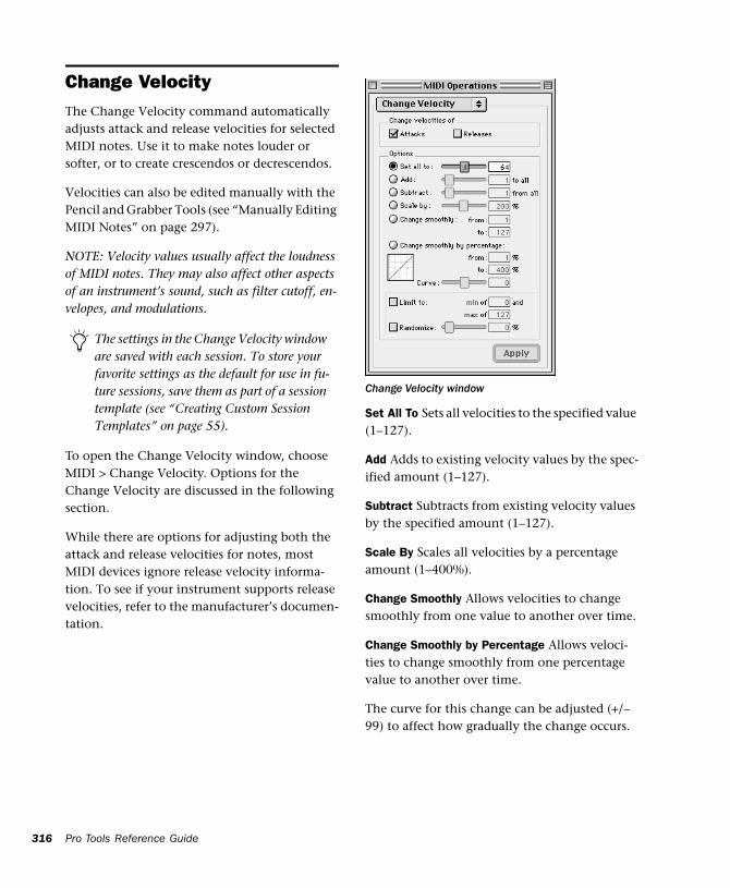
316
Change VelocityThe Change Velocity command automatically adjusts attack and release velocities for selected MIDI notes. Use it to make notes louder or softer, or to create crescendos or decrescendos.
Velocities can also be edited manually with the Pencil and Grabber Tools (see “Manually Editing MIDI Notes” on page 297).
NOTE: Velocity values usually affect the loudness of MIDI notes. They may also affect other aspects of an instrument’s sound, such as filter cutoff, en-velopes, and modulations.
To open the Change Velocity window, choose MIDI > Change Velocity. Options for the Change Velocity are discussed in the following section.
While there are options for adjusting both the attack and release velocities for notes, most MIDI devices ignore release velocity informa-tion. To see if your instrument supports release velocities, refer to the manufacturer’s documen-tation.
The settings in the Change Velocity window are saved with each session. To store your favorite settings as the default for use in fu-ture sessions, save them as part of a session template (see “Creating Custom Session Templates” on page 55).
Pro Tools Reference Guide
Set All To Sets all velocities to the specified value (1–127).
Add Adds to existing velocity values by the spec-ified amount (1–127).
Subtract Subtracts from existing velocity values by the specified amount (1–127).
Scale By Scales all velocities by a percentage amount (1–400%).
Change Smoothly Allows velocities to change smoothly from one value to another over time.
Change Smoothly by Percentage Allows veloci-ties to change smoothly from one percentage value to another over time.
The curve for this change can be adjusted (+/– 99) to affect how gradually the change occurs.
Change Velocity window
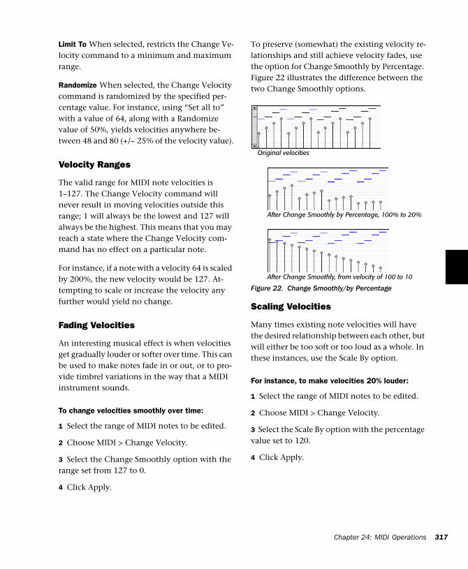
Limit To When selected, restricts the Change Ve-locity command to a minimum and maximum range.
Randomize When selected, the Change Velocity command is randomized by the specified per-centage value. For instance, using “Set all to” with a value of 64, along with a Randomize value of 50%, yields velocities anywhere be-tween 48 and 80 (+/– 25% of the velocity value).
Velocity Ranges
The valid range for MIDI note velocities is 1–127. The Change Velocity command will never result in moving velocities outside this range; 1 will always be the lowest and 127 will always be the highest. This means that you may reach a state where the Change Velocity com-mand has no effect on a particular note.
For instance, if a note with a velocity 64 is scaled by 200%, the new velocity would be 127. At-tempting to scale or increase the velocity any further would yield no change.
Fading Velocities
An interesting musical effect is when velocities get gradually louder or softer over time. This can be used to make notes fade in or out, or to pro-vide timbrel variations in the way that a MIDI instrument sounds.
To change velocities smoothly over time:
1 Select the range of MIDI notes to be edited.
2 Choose MIDI > Change Velocity.
3 Select the Change Smoothly option with the range set from 127 to 0.
4 Click Apply.
To preserve (somewhat) the existing velocity re-lationships and still achieve velocity fades, use the option for Change Smoothly by Percentage. Figure 22 illustrates the difference between the two Change Smoothly options.
Scaling Velocities
Many times existing note velocities will have the desired relationship between each other, but will either be too soft or too loud as a whole. In these instances, use the Scale By option.
For instance, to make velocities 20% louder:
1 Select the range of MIDI notes to be edited.
2 Choose MIDI > Change Velocity.
3 Select the Scale By option with the percentage value set to 120.
4 Click Apply.
Figure 22. Change Smoothly/by Percentage
Original velocities
After Change Smoothly by Percentage, 100% to 20%
After Change Smoothly, from velocity of 100 to 10
Chapter 24: MIDI Operations 317
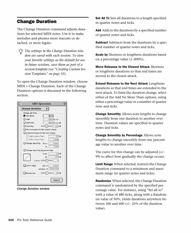
318
Change DurationThe Change Duration command adjusts dura-tions for selected MIDI notes. Use it to make melodies and phrases more staccato or de-tached, or more legato.
To open the Change Duration window, choose MIDI > Change Duration. Each of the Change Duration options is discussed in the following section.
The settings in the Change Duration win-dow are saved with each session. To store your favorite settings as the default for use in future sessions, save them as part of a session template (see “Creating Custom Ses-sion Templates” on page 55).
Change Duration window
Pro Tools Reference Guide
Set All To Sets all durations to a length specified in quarter notes and ticks.
Add Adds to the durations by a specified number of quarter notes and ticks.
Subtract Subtracts from the durations by a spec-ified number of quarter notes and ticks.
Scale by Shortens or lengthens durations based on a percentage value (1–400%).
Move Releases to the Closest Attack Shortens or lengthens durations so that end times are moved to the closest attack.
Extend Releases to the Next Attack Lengthens durations so that end times are extended to the next attack. To limit the duration change, select either of the Add No More Than options, using either a percentage value or a number of quarter note and ticks.
Change Smoothly Allows note lengths to change smoothly from one duration to another over time. Duration values are specified in quarter notes and ticks.
Change Smoothly by Percentage Allows note lengths to change smoothly from one percent-age value to another over time.
The curve for this change can be adjusted (+/– 99) to affect how gradually the change occurs.
Limit Range When selected, restricts the Change Duration command to a minimum and maxi-mum range (in quarter notes and ticks).
Randomize When selected, the Change Duration command is randomized by the specified per-centage value. For instance, using “Set all to” with a value of 480 ticks, along with a Random-ize value of 50%, yields durations anywhere be-tween 360 and 600 (+/– 25% of the duration value).
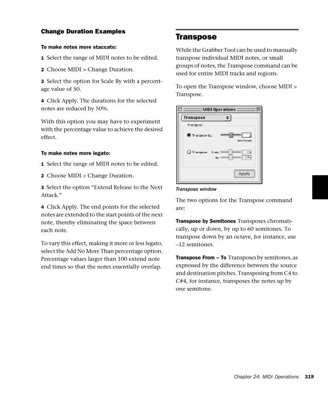
Change Duration Examples
To make notes more staccato:
1 Select the range of MIDI notes to be edited.
2 Choose MIDI > Change Duration.
3 Select the option for Scale By with a percent-age value of 50.
4 Click Apply. The durations for the selected notes are reduced by 50%.
With this option you may have to experiment with the percentage value to achieve the desired effect.
To make notes more legato:
1 Select the range of MIDI notes to be edited.
2 Choose MIDI > Change Duration.
3 Select the option “Extend Release to the Next Attack.”
4 Click Apply. The end points for the selected notes are extended to the start points of the next note, thereby eliminating the space between each note.
To vary this effect, making it more or less legato, select the Add No More Than percentage option. Percentage values larger than 100 extend note end times so that the notes essentially overlap.
TransposeWhile the Grabber Tool can be used to manually transpose individual MIDI notes, or small groups of notes, the Transpose command can be used for entire MIDI tracks and regions.
To open the Transpose window, choose MIDI > Transpose.
The two options for the Transpose command are:
Transpose by Semitones Transposes chromati-cally, up or down, by up to 60 semitones. To transpose down by an octave, for instance, use –12 semitones.
Transpose From – To Transposes by semitones, as expressed by the difference between the source and destination pitches. Transposing from C4 to C#4, for instance, transposes the notes up by one semitone.
Transpose window
Chapter 24: MIDI Operations 319
320
One of the more common uses for Transpose is to change the key for your MIDI tracks. You can define an Edit Group for MIDI tracks that want to transpose, making sure to exclude any drum tracks from the group so they aren’t transposed.
To transpose MIDI notes to another key:
1 If you will be transposing a group of tracks, make sure to enable the Edit Group.
2 With the Selector or Grabber, select the range of MIDI notes to be transposed.
3 Choose MIDI > Transpose.
4 Select the option for Transpose From–To.
5 Set the “From” and “To” values, for instance, to C4 and E4 to transpose from C Major to E Major.
With either of the pitch fields selected, you can play a note on your MIDI controller to automat-ically enter it as the pitch value.
6 Click Apply.
It is also common to transpose MIDI tracks up or down by an octave.
To transpose a MIDI track up by an octave:
1 With the Selector, triple-click in the track to select all of its notes.
2 Choose MIDI > Transpose.
3 Select the Transpose By option.
4 Enter a value of 12 semitones and then click Apply.
Pro Tools Reference Guide
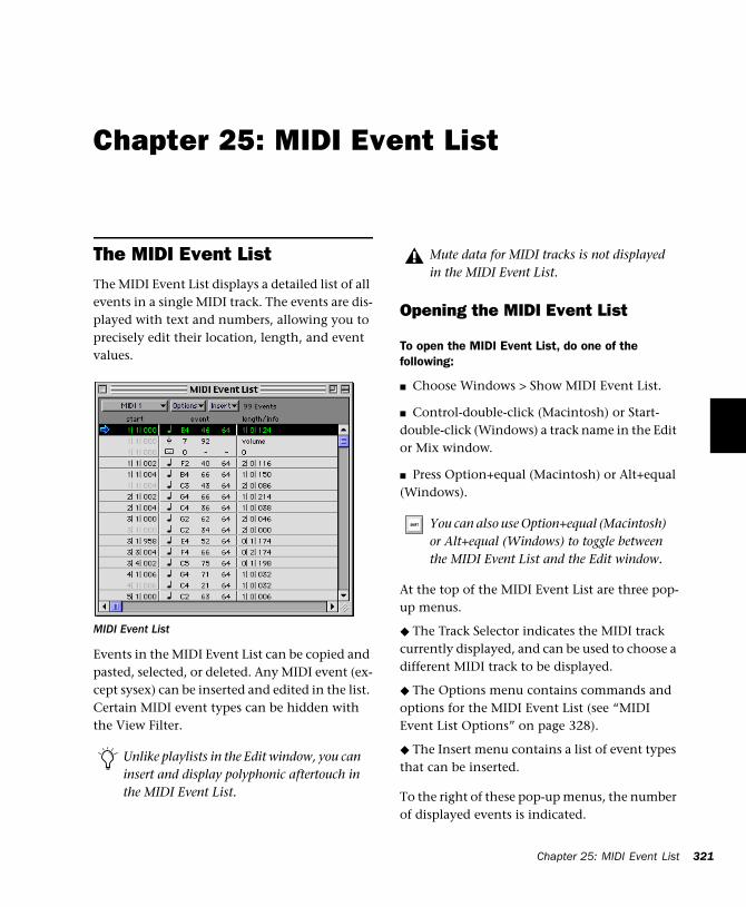
Chapter 25: MIDI Event List
The MIDI Event ListThe MIDI Event List displays a detailed list of all events in a single MIDI track. The events are dis-played with text and numbers, allowing you to precisely edit their location, length, and event values.
Events in the MIDI Event List can be copied and pasted, selected, or deleted. Any MIDI event (ex-cept sysex) can be inserted and edited in the list. Certain MIDI event types can be hidden with the View Filter.
MIDI Event List
Unlike playlists in the Edit window, you can insert and display polyphonic aftertouch in the MIDI Event List.
Opening the MIDI Event List
To open the MIDI Event List, do one of the following:
■ Choose Windows > Show MIDI Event List.
■ Control-double-click (Macintosh) or Start-double-click (Windows) a track name in the Edit or Mix window.
■ Press Option+equal (Macintosh) or Alt+equal (Windows).
At the top of the MIDI Event List are three pop-up menus.
◆ The Track Selector indicates the MIDI track currently displayed, and can be used to choose a different MIDI track to be displayed.
◆ The Options menu contains commands and options for the MIDI Event List (see “MIDI Event List Options” on page 328).
◆ The Insert menu contains a list of event types that can be inserted.
To the right of these pop-up menus, the number of displayed events is indicated.
Mute data for MIDI tracks is not displayed in the MIDI Event List.
You can also use Option+equal (Macintosh) or Alt+equal (Windows) to toggle between the MIDI Event List and the Edit window.
Chapter 25: MIDI Event List 321
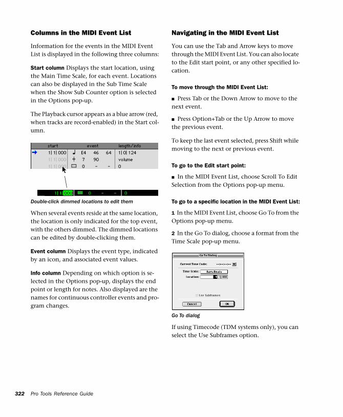
322
Columns in the MIDI Event List
Information for the events in the MIDI Event List is displayed in the following three columns:
Start column Displays the start location, using the Main Time Scale, for each event. Locations can also be displayed in the Sub Time Scale when the Show Sub Counter option is selected in the Options pop-up.
The Playback cursor appears as a blue arrow (red, when tracks are record-enabled) in the Start col-umn.
When several events reside at the same location, the location is only indicated for the top event, with the others dimmed. The dimmed locations can be edited by double-clicking them.
Event column Displays the event type, indicated by an icon, and associated event values.
Info column Depending on which option is se-lected in the Options pop-up, displays the end point or length for notes. Also displayed are the names for continuous controller events and pro-gram changes.
Double-click dimmed locations to edit them
Pro Tools Reference Guide
Navigating in the MIDI Event List
You can use the Tab and Arrow keys to move through the MIDI Event List. You can also locate to the Edit start point, or any other specified lo-cation.
To move through the MIDI Event List:
■ Press Tab or the Down Arrow to move to the next event.
■ Press Option+Tab or the Up Arrow to move the previous event.
To keep the last event selected, press Shift while moving to the next or previous event.
To go to the Edit start point:
■ In the MIDI Event List, choose Scroll To Edit Selection from the Options pop-up menu.
To go to a specific location in the MIDI Event List:
1 In the MIDI Event List, choose Go To from the Options pop-up menu.
2 In the Go To dialog, choose a format from the Time Scale pop-up menu.
If using Timecode (TDM systems only), you can select the Use Subframes option.
Go To dialog
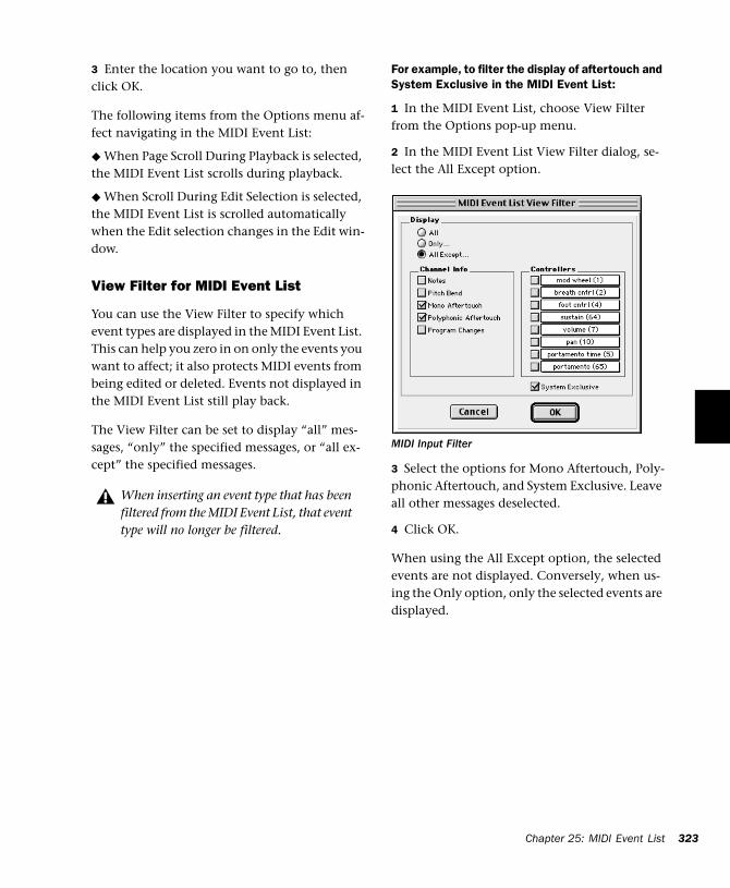
3 Enter the location you want to go to, then click OK.
The following items from the Options menu af-fect navigating in the MIDI Event List:
◆ When Page Scroll During Playback is selected, the MIDI Event List scrolls during playback.
◆ When Scroll During Edit Selection is selected, the MIDI Event List is scrolled automatically when the Edit selection changes in the Edit win-dow.
View Filter for MIDI Event List
You can use the View Filter to specify which event types are displayed in the MIDI Event List. This can help you zero in on only the events you want to affect; it also protects MIDI events from being edited or deleted. Events not displayed in the MIDI Event List still play back.
The View Filter can be set to display “all” mes-sages, “only” the specified messages, or “all ex-cept” the specified messages.
When inserting an event type that has been filtered from the MIDI Event List, that event type will no longer be filtered.
For example, to filter the display of aftertouch and System Exclusive in the MIDI Event List:
1 In the MIDI Event List, choose View Filter from the Options pop-up menu.
2 In the MIDI Event List View Filter dialog, se-lect the All Except option.
3 Select the options for Mono Aftertouch, Poly-phonic Aftertouch, and System Exclusive. Leave all other messages deselected.
4 Click OK.
When using the All Except option, the selected events are not displayed. Conversely, when us-ing the Only option, only the selected events are displayed.
MIDI Input Filter
Chapter 25: MIDI Event List 323
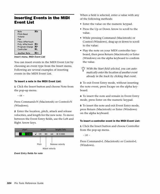
324
Inserting Events in the MIDI Event List
You can insert events in the MIDI Event List by choosing an event type from the Insert menu. Following are several examples of inserting events in the MIDI Event List.
To insert a note in the MIDI Event List:
1 Click the Insert button and choose Note from the pop-up menu.
– or –
Press Command+N (Macintosh) or Control+N (Windows).
2 Enter the location, pitch, attack and release velocities, and length for the new note. To move between the Event Entry fields, use the Left and Right Arrow keys.
Insert menu, MIDI Event List
Event Entry fields for note
Pitch
Attack velocity
Release velocity
Pro Tools Reference Guide
When a field is selected, enter a value with any of the following methods:
• Enter the value on the numeric keypad.
• Press the Up or Down Arrow to scroll to the value.
• While pressing Command (Macintosh) or Control (Windows), drag up or down to scroll to the value:
• Play the note on your MIDI controller key-board, then press Return (Macintosh) or Enter (Windows) on the alpha keyboard to confirm the value.
3 To exit Event Entry mode, without inserting the note event, press Escape on the alpha key-board.
4 To insert the note and remain in Event Entry mode, press Enter on the numeric keypad.
5 To insert the note and exit Event Entry mode, press Return (Macintosh) or Enter (Windows) on the alpha keyboard.
To insert a controller event in the MIDI Event List:
1 Click the Insert button and choose Controller from the pop-up menu.
– or –
Press Command+L (Macintosh) or Control+L (Windows).
With the Start field selected, you can auto-matically enter the location of another event already in the track by clicking that event.
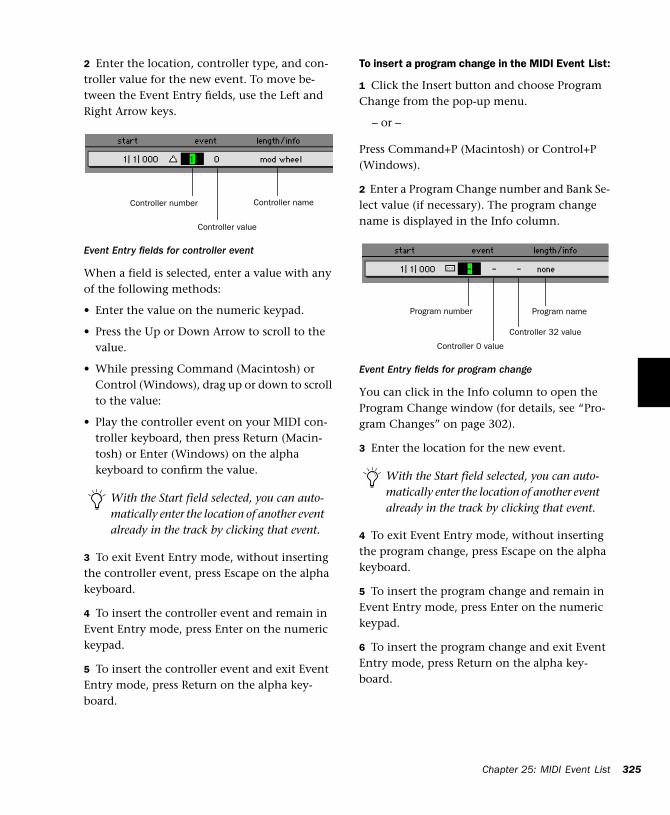
2 Enter the location, controller type, and con-troller value for the new event. To move be-tween the Event Entry fields, use the Left and Right Arrow keys.
When a field is selected, enter a value with any of the following methods:
• Enter the value on the numeric keypad.
• Press the Up or Down Arrow to scroll to the value.
• While pressing Command (Macintosh) or Control (Windows), drag up or down to scroll to the value:
• Play the controller event on your MIDI con-troller keyboard, then press Return (Macin-tosh) or Enter (Windows) on the alpha keyboard to confirm the value.
3 To exit Event Entry mode, without inserting the controller event, press Escape on the alpha keyboard.
4 To insert the controller event and remain in Event Entry mode, press Enter on the numeric keypad.
5 To insert the controller event and exit Event Entry mode, press Return on the alpha key-board.
Event Entry fields for controller event
With the Start field selected, you can auto-matically enter the location of another event already in the track by clicking that event.
Controller number Controller name
Controller value
To insert a program change in the MIDI Event List:
1 Click the Insert button and choose Program Change from the pop-up menu.
– or –
Press Command+P (Macintosh) or Control+P (Windows).
2 Enter a Program Change number and Bank Se-lect value (if necessary). The program change name is displayed in the Info column.
You can click in the Info column to open the Program Change window (for details, see “Pro-gram Changes” on page 302).
3 Enter the location for the new event.
4 To exit Event Entry mode, without inserting the program change, press Escape on the alpha keyboard.
5 To insert the program change and remain in Event Entry mode, press Enter on the numeric keypad.
6 To insert the program change and exit Event Entry mode, press Return on the alpha key-board.
Event Entry fields for program change
With the Start field selected, you can auto-matically enter the location of another event already in the track by clicking that event.
Program number Program name
Controller 0 value
Controller 32 value
Chapter
25: MIDI Event List 325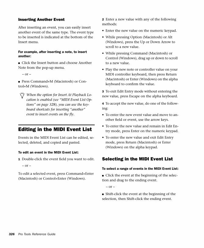
326
Inserting Another Event
After inserting an event, you can easily insert another event of the same type. The event type to be inserted is indicated at the bottom of the Insert menu.
For example, after inserting a note, to insert another:
■ Click the Insert button and choose Another Note from the pop-up menu.
– or –
■ Press Command+M (Macintosh) or Con-trol+M (Windows).
Editing in the MIDI Event ListEvents in the MIDI Event List can be edited, se-lected, deleted, and copied and pasted.
To edit an event in the MIDI Event List:
1 Double-click the event field you want to edit.
– or –
To edit a selected event, press Command+Enter (Macintosh) or Control+Enter (Windows).
When the option for Insert At Playback Lo-cation is enabled (see “MIDI Event List Op-tions” on page 328), you can use the key-board shortcuts for inserting “another” event to insert events on the fly.
Pro Tools Reference Guide
2 Enter a new value with any of the following methods:
• Enter the new value on the numeric keypad.
• While pressing Option (Macintosh) or Alt (Windows), press the Up or Down Arrow to scroll to a new value.
• While pressing Command (Macintosh) or Control (Windows), drag up or down to scroll to a new value.
• Play the new note or controller value on your MIDI controller keyboard, then press Return (Macintosh) or Enter (Windows) on the alpha keyboard to confirm the value.
3 To exit Edit Entry mode without entering the new value, press Escape on the alpha keyboard.
4 To accept the new value, do one of the follow-ing:
• To enter the new event value and move to an-other field or event, use the arrow keys.
• To enter the new value and remain in Edit En-try mode, press Enter on the numeric keypad.
• To enter the new value and exit Edit Entry mode, press Return (Macintosh) or Enter (Windows) on the alpha keypad.
Selecting in the MIDI Event List
To select a range of events in the MIDI Event List:
■ Click the event at the beginning of the selec-tion and drag to the ending event.
– or –
■ Shift-click the event at the beginning of the selection, then Shift-click the ending event.
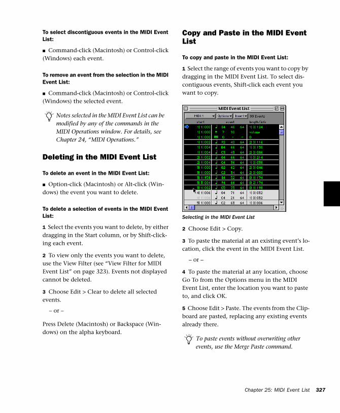
To select discontiguous events in the MIDI Event List:
■ Command-click (Macintosh) or Control-click (Windows) each event.
To remove an event from the selection in the MIDI Event List:
■ Command-click (Macintosh) or Control-click (Windows) the selected event.
Deleting in the MIDI Event List
To delete an event in the MIDI Event List:
■ Option-click (Macintosh) or Alt-click (Win-dows) the event you want to delete.
To delete a selection of events in the MIDI Event List:
1 Select the events you want to delete, by either dragging in the Start column, or by Shift-click-ing each event.
2 To view only the events you want to delete, use the View Filter (see “View Filter for MIDI Event List” on page 323). Events not displayed cannot be deleted.
3 Choose Edit > Clear to delete all selected events.
– or –
Press Delete (Macintosh) or Backspace (Win-dows) on the alpha keyboard.
Notes selected in the MIDI Event List can be modified by any of the commands in the MIDI Operations window. For details, see Chapter 24, “MIDI Operations.”
Copy and Paste in the MIDI Event List
To copy and paste in the MIDI Event List:
1 Select the range of events you want to copy by dragging in the MIDI Event List. To select dis-contiguous events, Shift-click each event you want to copy.
2 Choose Edit > Copy.
3 To paste the material at an existing event’s lo-cation, click the event in the MIDI Event List.
– or –
4 To paste the material at any location, choose Go To from the Options menu in the MIDI Event List, enter the location you want to paste to, and click OK.
5 Choose Edit > Paste. The events from the Clip-board are pasted, replacing any existing events already there.
Selecting in the MIDI Event List
To paste events without overwriting other events, use the Merge Paste command.
Chapter 25: MIDI Event List 327
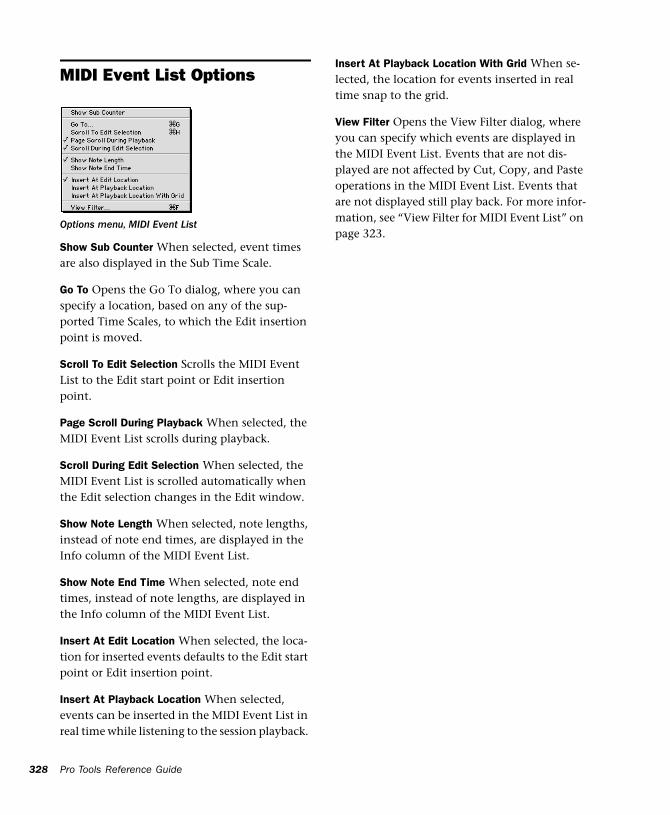
328
MIDI Event List Options
Show Sub Counter When selected, event times are also displayed in the Sub Time Scale.
Go To Opens the Go To dialog, where you can specify a location, based on any of the sup-ported Time Scales, to which the Edit insertion point is moved.
Scroll To Edit Selection Scrolls the MIDI Event List to the Edit start point or Edit insertion point.
Page Scroll During Playback When selected, the MIDI Event List scrolls during playback.
Scroll During Edit Selection When selected, the MIDI Event List is scrolled automatically when the Edit selection changes in the Edit window.
Show Note Length When selected, note lengths, instead of note end times, are displayed in the Info column of the MIDI Event List.
Show Note End Time When selected, note end times, instead of note lengths, are displayed in the Info column of the MIDI Event List.
Insert At Edit Location When selected, the loca-tion for inserted events defaults to the Edit start point or Edit insertion point.
Insert At Playback Location When selected, events can be inserted in the MIDI Event List in real time while listening to the session playback.
Options menu, MIDI Event List
Pro Tools Reference Guide
Insert At Playback Location With Grid When se-lected, the location for events inserted in real time snap to the grid.
View Filter Opens the View Filter dialog, where you can specify which events are displayed in the MIDI Event List. Events that are not dis-played are not affected by Cut, Copy, and Paste operations in the MIDI Event List. Events that are not displayed still play back. For more infor-mation, see “View Filter for MIDI Event List” on page 323.
Part VI: Mixing
329

330
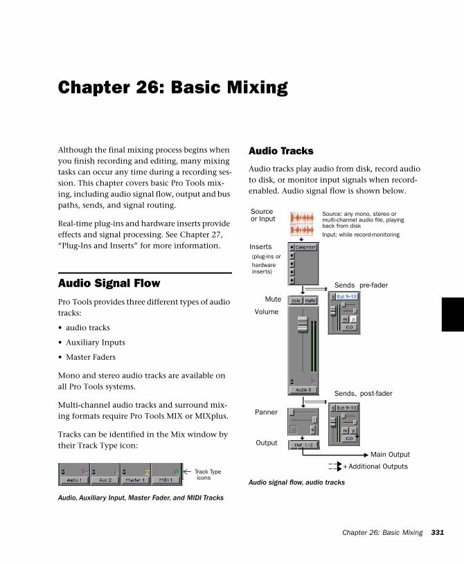
Chapter 26: Basic Mixing
Although the final mixing process begins when you finish recording and editing, many mixing tasks can occur any time during a recording ses-sion. This chapter covers basic Pro Tools mix-ing, including audio signal flow, output and bus paths, sends, and signal routing.
Real-time plug-ins and hardware inserts provide effects and signal processing. See Chapter 27, “Plug-Ins and Inserts” for more information.
Audio Signal FlowPro Tools provides three different types of audio tracks:
• audio tracks
• Auxiliary Inputs
• Master Faders
Mono and stereo audio tracks are available on all Pro Tools systems.
Multi-channel audio tracks and surround mix-ing formats require Pro Tools MIX or MIXplus.
Tracks can be identified in the Mix window by their Track Type icon:
Audio, Auxiliary Input, Master Fader, and MIDI Tracks
Track Type icons
Audio Tracks
Audio tracks play audio from disk, record audio to disk, or monitor input signals when record-enabled. Audio signal flow is shown below.
Audio signal flow, audio tracks
Inserts
Sends
Volume
(plug-ins or hardware
Main Output
pre-fader
Mute
Panner
Additional Outputs
Sends, post-fader
inserts)
Output
+
Source: any mono, stereo or multi-channel audio file, playingback from disk
Input: while record-monitoring
Source or Input
Chapter 26: Basic Mixing 331
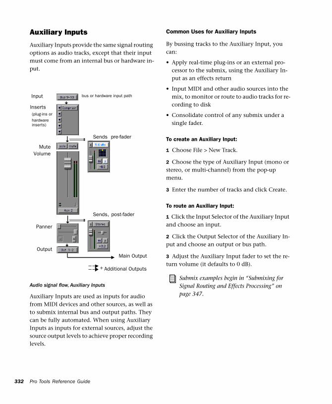
332
Auxiliary Inputs
Auxiliary Inputs provide the same signal routing options as audio tracks, except that their input must come from an internal bus or hardware in-put.
Auxiliary Inputs are used as inputs for audio from MIDI devices and other sources, as well as to submix internal bus and output paths. They can be fully automated. When using Auxiliary Inputs as inputs for external sources, adjust the source output levels to achieve proper recording levels.
Audio signal flow, Auxiliary Inputs
Input
Inserts
Sends
Volume
(plug-ins or hardware
Main Output
pre-fader
Mute
Panner
Additional Outputs
Sends, post-fader
inserts)
Output
+
bus or hardware input path
Pro Tools Reference Guide
Common Uses for Auxiliary Inputs
By bussing tracks to the Auxiliary Input, you can:
• Apply real-time plug-ins or an external pro-cessor to the submix, using the Auxiliary In-put as an effects return
• Input MIDI and other audio sources into the mix, to monitor or route to audio tracks for re-cording to disk
• Consolidate control of any submix under a single fader.
To create an Auxiliary Input:
1 Choose File > New Track.
2 Choose the type of Auxiliary Input (mono or stereo, or multi-channel) from the pop-up menu.
3 Enter the number of tracks and click Create.
To route an Auxiliary Input:
1 Click the Input Selector of the Auxiliary Input and choose an input.
2 Click the Output Selector of the Auxiliary In-put and choose an output or bus path.
3 Adjust the Auxiliary Input fader to set the re-turn volume (it defaults to 0 dB).
Submix examples begin in “Submixing for Signal Routing and Effects Processing” on page 347.
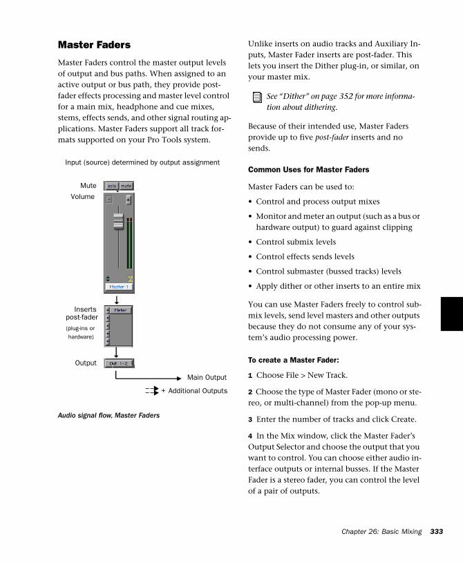
Master Faders
Master Faders control the master output levels of output and bus paths. When assigned to an active output or bus path, they provide post-fader effects processing and master level control for a main mix, headphone and cue mixes, stems, effects sends, and other signal routing ap-plications. Master Faders support all track for-mats supported on your Pro Tools system.
Audio signal flow, Master Faders
Input (source) determined by output assignment
Inserts
Volume
(plug-ins or hardware)
Main Output
Mute
Additional Outputs
post-fader
Output
+
Unlike inserts on audio tracks and Auxiliary In-puts, Master Fader inserts are post-fader. This lets you insert the Dither plug-in, or similar, on your master mix.
Because of their intended use, Master Faders provide up to five post-fader inserts and no sends.
Common Uses for Master Faders
Master Faders can be used to:
• Control and process output mixes
• Monitor and meter an output (such as a bus or hardware output) to guard against clipping
• Control submix levels
• Control effects sends levels
• Control submaster (bussed tracks) levels
• Apply dither or other inserts to an entire mix
You can use Master Faders freely to control sub-mix levels, send level masters and other outputs because they do not consume any of your sys-tem’s audio processing power.
To create a Master Fader:
1 Choose File > New Track.
2 Choose the type of Master Fader (mono or ste-reo, or multi-channel) from the pop-up menu.
3 Enter the number of tracks and click Create.
4 In the Mix window, click the Master Fader’s Output Selector and choose the output that you want to control. You can choose either audio in-terface outputs or internal busses. If the Master Fader is a stereo fader, you can control the level of a pair of outputs.
See “Dither” on page 352 for more informa-tion about dithering.
Chapter 26: Basic Mixing 333
334
To use Master Faders as a master volume control for all tracks in a session:
1 Choose File > New Track.
2 Choose the type of Master Fader from the pop-up menu.
3 Click Create.
4 Set the outputs of all audio tracks in the ses-sion to outputs 1–2 and set the panning of each track.
5 Set the output of the Master Fader to your main output path.
Master Fader Meters
Meters on Master faders always show post-fader levels, regardless of the Pre-Fader Metering set-ting in the Operations menu.
Master Faders and Paths
Master Faders can be assigned to main and sub-paths. When more than one Master Fader is as-signed to the same output or bus path, only one can be active at the same time. If you try to as-sign a Master Fader to a main or sub-path that is already actively assigned on another Master Fader, the new assignment will be assigned, but inactive. Master Faders can be assigned different sub-paths of the same main path, as long as the sub-paths do not overlap.
Active and Inactive Master Faders
When a Master Fader track is inactive, its associ-ated plug-ins, I/O assignments, and their re-sources are released and available for other uses in the session.
When a Master Fader output assignment (path assignment) is made inactive, the Master Fader no longer controls the master gain of that path.
Pro Tools Reference Guide
When you duplicate a Master Fader track, the duplicated track’s assignment will be inactive. See “Master Faders and Paths” on page 334 for more information.
Plug-Ins and Inserts
Five inserts are available on each audio channel. Each insert can be either a hardware insert or a software plug-in insert. Plug-ins and hardware in-serts route the signal from the track through the effect of your choice, and automatically return it to the same track. Inserts on audio tracks and Auxiliary Inputs are pre-fader. Inserts on Master Faders are post-fader.
On TDM systems, RTAS plug-ins can be inserted on audio tracks, but not on Auxiliary Inputs or Master Faders.
Hardware inserts send and return the signal to corresponding input and output channels of an audio interface.
Track Output Format and Plug-Ins
Plug-ins provide mono, stereo, multi-mono and multi-channel versions (not all versions are sup-ported by all plug-in manufacturers or on all sys-tems).
Because inserts process in series, changing the plug-in format can alter the channel format. For example, inserting a mono-to-stereo plug-in on a mono Auxiliary Input changes the signal path from that plug-in through the rest of the track. This restricts all hardware inserts or plug-ins af-ter the stereo plug-in to be stereo-in/stereo-out plug-ins (or supported multi-channel format).
See Chapter 27, “Plug-Ins and Inserts” for details about using plug-ins and inserts.
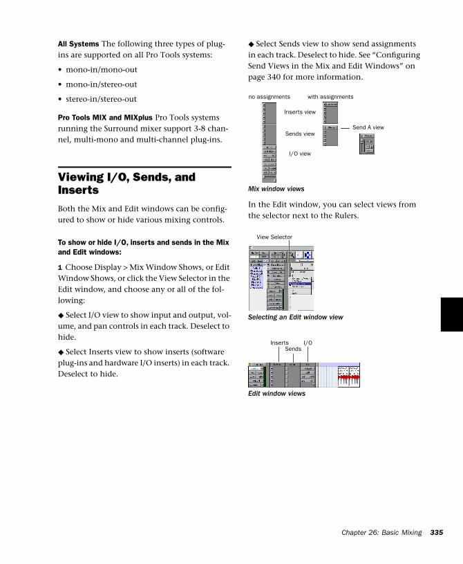
All Systems The following three types of plug-ins are supported on all Pro Tools systems:
• mono-in/mono-out
• mono-in/stereo-out
• stereo-in/stereo-out
Pro Tools MIX and MIXplus Pro Tools systems running the Surround mixer support 3-8 chan-nel, multi-mono and multi-channel plug-ins.
Viewing I/O, Sends, and Inserts Both the Mix and Edit windows can be config-ured to show or hide various mixing controls.
To show or hide I/O, inserts and sends in the Mix and Edit windows:
1 Choose Display > Mix Window Shows, or Edit Window Shows, or click the View Selector in the Edit window, and choose any or all of the fol-lowing:
◆ Select I/O view to show input and output, vol-ume, and pan controls in each track. Deselect to hide.
◆ Select Inserts view to show inserts (software plug-ins and hardware I/O inserts) in each track. Deselect to hide.
◆ Select Sends view to show send assignments in each track. Deselect to hide. See “Configuring Send Views in the Mix and Edit Windows” on page 340 for more information.
In the Edit window, you can select views from the selector next to the Rulers.
Mix window views
Selecting an Edit window view
Edit window views
Inserts view
Sends view
I/O view
with assignmentsno assignments
Send A view
View Selector
InsertsSends
I/O
Chapter 26: Basic Mixing 335
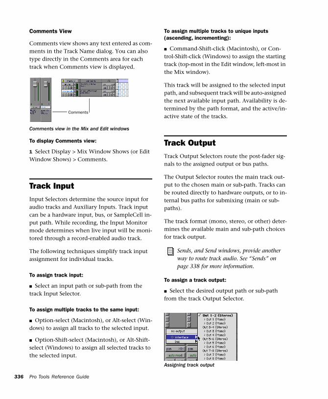
336
Comments View
Comments view shows any text entered as com-ments in the Track Name dialog. You can also type directly in the Comments area for each track when Comments view is displayed.
To display Comments view:
1 Select Display > Mix Window Shows (or Edit Window Shows) > Comments.
Track InputInput Selectors determine the source input for audio tracks and Auxiliary Inputs. Track input can be a hardware input, bus, or SampleCell in-put path. While recording, the Input Monitor mode determines when live input will be moni-tored through a record-enabled audio track.
The following techniques simplify track input assignment for individual tracks.
To assign track input:
■ Select an input path or sub-path from the track Input Selector.
To assign multiple tracks to the same input:
■ Option-select (Macintosh), or Alt-select (Win-dows) to assign all tracks to the selected input.
■ Option-Shift-select (Macintosh), or Alt-Shift-select (Windows) to assign all selected tracks to the selected input.
Comments view in the Mix and Edit windows
Comments
Pro Tools Reference Guide
To assign multiple tracks to unique inputs (ascending, incrementing):
■ Command-Shift-click (Macintosh), or Con-trol-Shift-click (Windows) to assign the starting track (top-most in the Edit window, left-most in the Mix window).
This track will be assigned to the selected input path, and subsequent track will be auto-assigned the next available input path. Availability is de-termined by the path format, and the active/in-active state of the tracks.
Track OutputTrack Output Selectors route the post-fader sig-nals to the assigned output or bus paths.
The Output Selector routes the main track out-put to the chosen main or sub-path. Tracks can be routed directly to hardware outputs, or to in-ternal bus paths for submixing (main or sub-paths).
The track format (mono, stereo, or other) deter-mines the available main and sub-path choices for track output.
To assign a track output:
■ Select the desired output path or sub-path from the track Output Selector.
Sends, and Send windows, provide another way to route track audio. See “Sends” on page 338 for more information.
Assigning track output
To assign all tracks to the same output:
■ While pressing Option-select (Macintosh) or Alt-select (Windows), assign any track output to also assign all tracks to the same path.
To assign all selected tracks to the same output:
■ While pressing Option+Shift (Macintosh), or Alt+Shift (Windows), assign any track to also as-sign all selected tracks to the same path.
Output Paths
When audio tracks, Auxiliary Inputs, and Mas-ter Faders are created, their mono, stereo, or multi-channel format is defined. This original format determines the track’s minimum insert, send, and output format.
• Mono tracks can be assigned to any available mono, stereo, or other r multi-channel main and sub-paths.
• Stereo tracks can be assigned to any available stereo or multi-channel main and sub-paths.
• Multi-channel can be assigned to any equal, or higher, format.
For example, on any stereo audio track, Auxil-iary Input, or Master Fader, the main track out-put can be assigned to any available stereo paths or insert, or any multi-channel paths of three or more channels (on supported systems).
Output Windows
Output windows provide the essential track mixing controls, as an alternative to Mix and Edit window views. Multi-channel Send and Output windows also provide expanded Panner views, and other surround-specific controls. (See Chapter 33, “Surround Panning and Mixing.”)
Output windows are useful in large sessions to leave important tracks in an anchored location, unaffected by Mix and Edit window (or control surface) banking. See “Opening and Managing Output Windows” on page 343.
Multiple Output Assignments
Pro Tools audio tracks and Auxiliary Inputs can have multiple track and send assignments. Mul-tiple outputs are limited only by the paths and resources available on your system.
Assigning to multiple paths is an efficient way to route an identical mix to other discrete out-puts, for simultaneous monitor feeds, head-phone mixes, or other situations where a paral-lel mix is needed. Master Faders can only be assigned to a single path.
To assign a track to multiple outputs:
1 Assign a main output path by selecting it from the track’s Output Selector.
2 Control-click to select an additional output path in the track’s Output Selector. The newly selected output destination is added as an addi-tional output.
Option-Control-click to add the assignment to all tracks, or Option-Shift-Control-click to add to all selected tracks.
Chapter 26: Basic Mixing 337
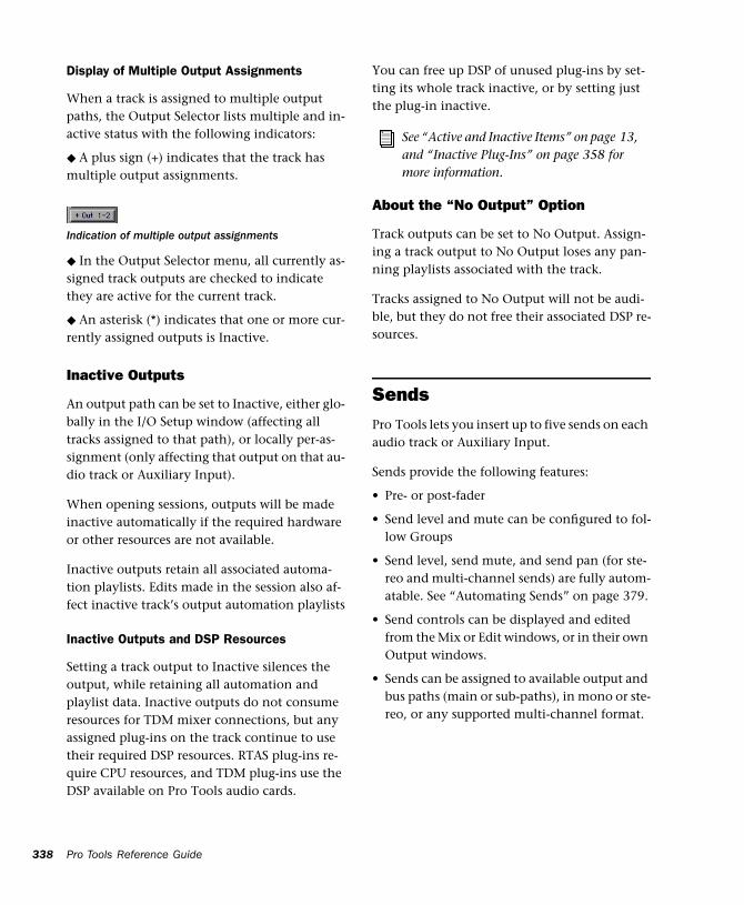
338
Display of Multiple Output Assignments
When a track is assigned to multiple output paths, the Output Selector lists multiple and in-active status with the following indicators:
◆ A plus sign (+) indicates that the track has multiple output assignments.
◆ In the Output Selector menu, all currently as-signed track outputs are checked to indicate they are active for the current track.
◆ An asterisk (*) indicates that one or more cur-rently assigned outputs is Inactive.
Inactive Outputs
An output path can be set to Inactive, either glo-bally in the I/O Setup window (affecting all tracks assigned to that path), or locally per-as-signment (only affecting that output on that au-dio track or Auxiliary Input).
When opening sessions, outputs will be made inactive automatically if the required hardware or other resources are not available.
Inactive outputs retain all associated automa-tion playlists. Edits made in the session also af-fect inactive track’s output automation playlists
Inactive Outputs and DSP Resources
Setting a track output to Inactive silences the output, while retaining all automation and playlist data. Inactive outputs do not consume resources for TDM mixer connections, but any assigned plug-ins on the track continue to use their required DSP resources. RTAS plug-ins re-quire CPU resources, and TDM plug-ins use the DSP available on Pro Tools audio cards.
Indication of multiple output assignments
Pro Tools Reference Guide
You can free up DSP of unused plug-ins by set-ting its whole track inactive, or by setting just the plug-in inactive.
About the “No Output” Option
Track outputs can be set to No Output. Assign-ing a track output to No Output loses any pan-ning playlists associated with the track.
Tracks assigned to No Output will not be audi-ble, but they do not free their associated DSP re-sources.
SendsPro Tools lets you insert up to five sends on each audio track or Auxiliary Input.
Sends provide the following features:
• Pre- or post-fader
• Send level and mute can be configured to fol-low Groups
• Send level, send mute, and send pan (for ste-reo and multi-channel sends) are fully autom-atable. See “Automating Sends” on page 379.
• Send controls can be displayed and edited from the Mix or Edit windows, or in their own Output windows.
• Sends can be assigned to available output and bus paths (main or sub-paths), in mono or ste-reo, or any supported multi-channel format.
See “Active and Inactive Items” on page 13, and “Inactive Plug-Ins” on page 358 for more information.
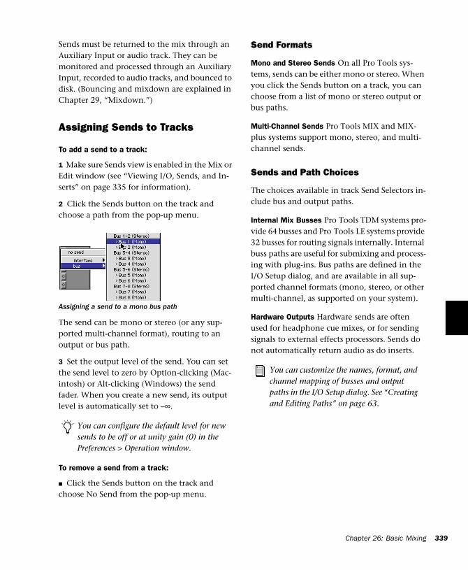
Sends must be returned to the mix through an Auxiliary Input or audio track. They can be monitored and processed through an Auxiliary Input, recorded to audio tracks, and bounced to disk. (Bouncing and mixdown are explained in Chapter 29, “Mixdown.”)
Assigning Sends to Tracks
To add a send to a track:
1 Make sure Sends view is enabled in the Mix or Edit window (see “Viewing I/O, Sends, and In-serts” on page 335 for information).
2 Click the Sends button on the track and choose a path from the pop-up menu.
The send can be mono or stereo (or any sup-ported multi-channel format), routing to an output or bus path.
3 Set the output level of the send. You can set the send level to zero by Option-clicking (Mac-intosh) or Alt-clicking (Windows) the send fader. When you create a new send, its output level is automatically set to –∞.
To remove a send from a track:
■ Click the Sends button on the track and choose No Send from the pop-up menu.
Assigning a send to a mono bus path
You can configure the default level for new sends to be off or at unity gain (0) in the Preferences > Operation window.
Send Formats
Mono and Stereo Sends On all Pro Tools sys-tems, sends can be either mono or stereo. When you click the Sends button on a track, you can choose from a list of mono or stereo output or bus paths.
Multi-Channel Sends Pro Tools MIX and MIX-plus systems support mono, stereo, and multi-channel sends.
Sends and Path Choices
The choices available in track Send Selectors in-clude bus and output paths.
Internal Mix Busses Pro Tools TDM systems pro-vide 64 busses and Pro Tools LE systems provide 32 busses for routing signals internally. Internal buss paths are useful for submixing and process-ing with plug-ins. Bus paths are defined in the I/O Setup dialog, and are available in all sup-ported channel formats (mono, stereo, or other multi-channel, as supported on your system).
Hardware Outputs Hardware sends are often used for headphone cue mixes, or for sending signals to external effects processors. Sends do not automatically return audio as do inserts.
You can customize the names, format, and channel mapping of busses and output paths in the I/O Setup dialog. See “Creating and Editing Paths” on page 63.
Chapter 26: Basic Mixing 339
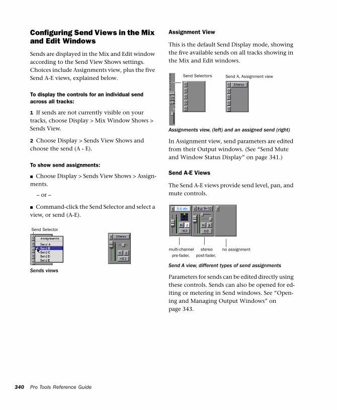
340
Configuring Send Views in the Mix and Edit Windows
Sends are displayed in the Mix and Edit window according to the Send View Shows settings. Choices include Assignments view, plus the five Send A-E views, explained below.
To display the controls for an individual send across all tracks:
1 If sends are not currently visible on your tracks, choose Display > Mix Window Shows > Sends View.
2 Choose Display > Sends View Shows and choose the send (A - E).
To show send assignments:
■ Choose Display > Sends View Shows > Assign-ments.
– or –
■ Command-click the Send Selector and select a view, or send (A-E).
Sends views
Send Selector
Pro Tools Reference Guide
Assignment View
This is the default Send Display mode, showing the five available sends on all tracks showing in the Mix and Edit windows.
In Assignment view, send parameters are edited from their Output windows. (See “Send Mute and Window Status Display” on page 341.)
Send A-E Views
The Send A-E views provide send level, pan, and mute controls.
Parameters for sends can be edited directly using these controls. Sends can also be opened for ed-iting or metering in Send windows. See “Open-ing and Managing Output Windows” on page 343.
Assignments view, (left) and an assigned send (right)
Send A view, different types of send assignments
Send Selectors Send A, Assignment view
pre-fader, multi-channel
post-fader, no assignmentstereo
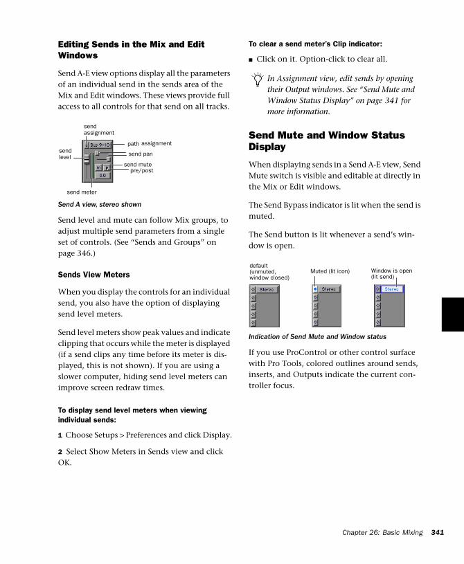
Editing Sends in the Mix and Edit Windows
Send A-E view options display all the parameters of an individual send in the sends area of the Mix and Edit windows. These views provide full access to all controls for that send on all tracks.
Send level and mute can follow Mix groups, to adjust multiple send parameters from a single set of controls. (See “Sends and Groups” on page 346.)
Sends View Meters
When you display the controls for an individual send, you also have the option of displaying send level meters.
Send level meters show peak values and indicate clipping that occurs while the meter is displayed (if a send clips any time before its meter is dis-played, this is not shown). If you are using a slower computer, hiding send level meters can improve screen redraw times.
To display send level meters when viewing individual sends:
1 Choose Setups > Preferences and click Display.
2 Select Show Meters in Sends view and click OK.
Send A view, stereo shown
send mute
send
path
send pan
send meter
send
pre/post
assignment
assignment
level
To clear a send meter’s Clip indicator:
■ Click on it. Option-click to clear all.
Send Mute and Window Status Display
When displaying sends in a Send A-E view, Send Mute switch is visible and editable at directly in the Mix or Edit windows.
The Send Bypass indicator is lit when the send is muted.
The Send button is lit whenever a send’s win-dow is open.
If you use ProControl or other control surface with Pro Tools, colored outlines around sends, inserts, and Outputs indicate the current con-troller focus.
In Assignment view, edit sends by opening their Output windows. See “Send Mute and Window Status Display” on page 341 for more information.
Indication of Send Mute and Window status
default Muted (lit icon) Window is open(unmuted,
window closed) (lit send)
Chapter 26: Basic Mixing 341
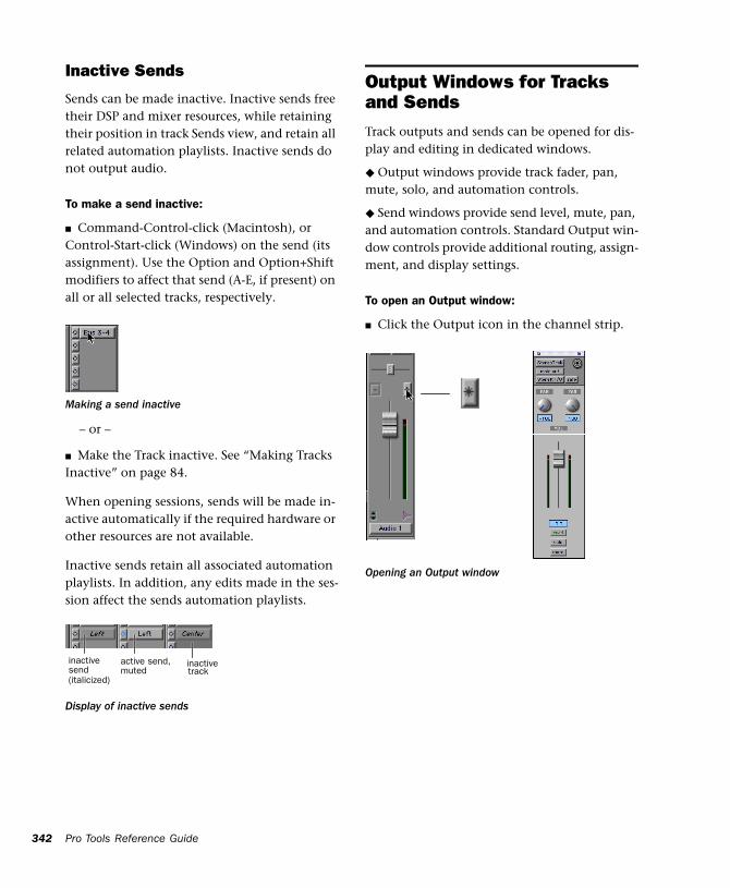
342
Inactive Sends
Sends can be made inactive. Inactive sends free their DSP and mixer resources, while retaining their position in track Sends view, and retain all related automation playlists. Inactive sends do not output audio.
To make a send inactive:
■ Command-Control-click (Macintosh), or Control-Start-click (Windows) on the send (its assignment). Use the Option and Option+Shift modifiers to affect that send (A-E, if present) on all or all selected tracks, respectively.
– or –
■ Make the Track inactive. See “Making Tracks Inactive” on page 84.
When opening sessions, sends will be made in-active automatically if the required hardware or other resources are not available.
Inactive sends retain all associated automation playlists. In addition, any edits made in the ses-sion affect the sends automation playlists.
Making a send inactive
Display of inactive sends
inactive
(italicized)
active send, inactivesend trackmuted
Pro Tools Reference Guide
Output Windows for Tracks and SendsTrack outputs and sends can be opened for dis-play and editing in dedicated windows.
◆ Output windows provide track fader, pan, mute, solo, and automation controls.
◆ Send windows provide send level, mute, pan, and automation controls. Standard Output win-dow controls provide additional routing, assign-ment, and display settings.
To open an Output window:
■ Click the Output icon in the channel strip.
Opening an Output window
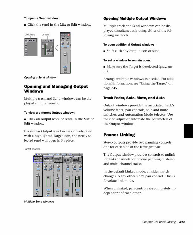
To open a Send window:
■ Click the send in the Mix or Edit window.
Opening and Managing Output Windows
Multiple track and Send windows can be dis-played simultaneously.
To view a different Output window:
■ Click an output icon, or send, in the Mix or Edit window.
If a similar Output window was already open with a highlighted Target icon, the newly se-lected send will open in its place.
Opening a Send window
Multiple Send windows
click here or here
Target enabled
Opening Multiple Output Windows
Multiple track and Send windows can be dis-played simultaneously using either of the fol-lowing methods.
To open additional Output windows:
■ Shift-click any output icon or send.
To set a window to remain open:
■ Make sure the Target is deselected (gray, un-lit).
Arrange multiple windows as needed. For addi-tional information, see “Using the Target” on page 345.
Track Fader, Solo, Mute, and Auto
Output windows provide the associated track’s volume fader, pan controls, solo and mute switches, and Automation Mode Selector. Use these to adjust or automate the parameters of the Output window.
Panner Linking
Stereo outputs provide two panning controls, one for each side of the left/right pair.
The Output window provides controls to unlink (or link) channels for precise panning of stereo and multi-channel tracks.
In the default Linked mode, all sides match changes to any other side’s pan control. This is Absolute link mode.
When unlinked, pan controls are completely in-dependent of each other.
Chapter 26: Basic Mixing 343
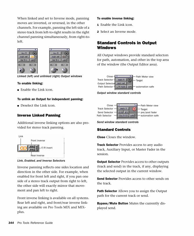
344
When linked and set to Inverse mode, panning moves are inverted, or reversed, in the other channels. For example, panning the left side of a stereo track from left-to-right results in the right channel panning simultaneously, from right-to-left.
To enable linking:
■ Enable the Link icon.
To unlink an Output for independent panning:
■ Deselect the Link icon.
Inverse Linked Panning
Additional inverse linking options are also pro-vided for stereo track panning.
Inverse panning reflects one sides location and direction in the other side. For example, when enabled for front left and right, if you pan one side of a stereo track output from right to left, the other side will exactly mirror that move-ment and pan left to right.
Front inverse linking is available on all systems. Rear left and right, and front/rear inverse link-ing are available on Pro Tools MIX and MIX-plus.
Linked (left) and unlinked (right) Output windows
Link, Enabled, and Inverse Selectors
Link
F/R invert
Front inverse
Rear inverse
Pro Tools Reference Guide
To enable inverse linking:
1 Enable the Link icon.
2 Select an Inverse mode.
Standard Controls in Output Windows
All Output windows provide standard selectors for path, automation, and other in the top area of the window (the Output Editor area).
Standard Controls
Close Closes the window.
Track Selector Provides access to any audio track, Auxiliary Input, or Master Fader in the session.
Output Selector Provides access to other outputs (track and send) in the track, if any, displaying the selected output in the current window.
Send Selector Provides access to other sends on the track.
Path Selector Allows you to assign the Output path for the current track or send.
Bypass/Mute Button Mutes the currently dis-played send.
Output window standard controls
Send window standard controls
automation safe
Target
Path Meter view
Path SelectorOutput Selector
Track SelectorClose
automation safepre/post faderTarget
Path Meter view
Path SelectorSend Selector
Track SelectorClose
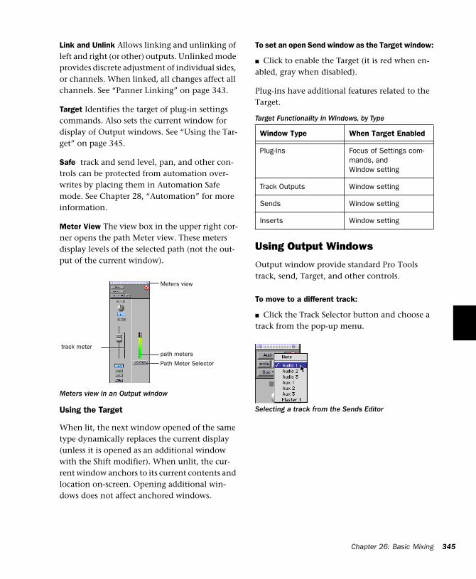
Link and Unlink Allows linking and unlinking of left and right (or other) outputs. Unlinked mode provides discrete adjustment of individual sides, or channels. When linked, all changes affect all channels. See “Panner Linking” on page 343.
Target Identifies the target of plug-in settings commands. Also sets the current window for display of Output windows. See “Using the Tar-get” on page 345.
Safe track and send level, pan, and other con-trols can be protected from automation over-writes by placing them in Automation Safe mode. See Chapter 28, “Automation” for more information.
Meter View The view box in the upper right cor-ner opens the path Meter view. These meters display levels of the selected path (not the out-put of the current window).
Using the Target
When lit, the next window opened of the same type dynamically replaces the current display (unless it is opened as an additional window with the Shift modifier). When unlit, the cur-rent window anchors to its current contents and location on-screen. Opening additional win-dows does not affect anchored windows.
Meters view in an Output window
path meters
Path Meter Selector
track meter
Meters view
To set an open Send window as the Target window:
■ Click to enable the Target (it is red when en-abled, gray when disabled).
Plug-ins have additional features related to the Target.
Using Output Windows
Output window provide standard Pro Tools track, send, Target, and other controls.
To move to a different track:
■ Click the Track Selector button and choose a track from the pop-up menu.
Target Functionality in Windows, by Type
Window Type When Target Enabled
Plug-Ins Focus of Settings com-mands, and Window setting
Track Outputs Window setting
Sends Window setting
Inserts Window setting
Selecting a track from the Sends Editor
Chapter 26: Basic Mixing 345
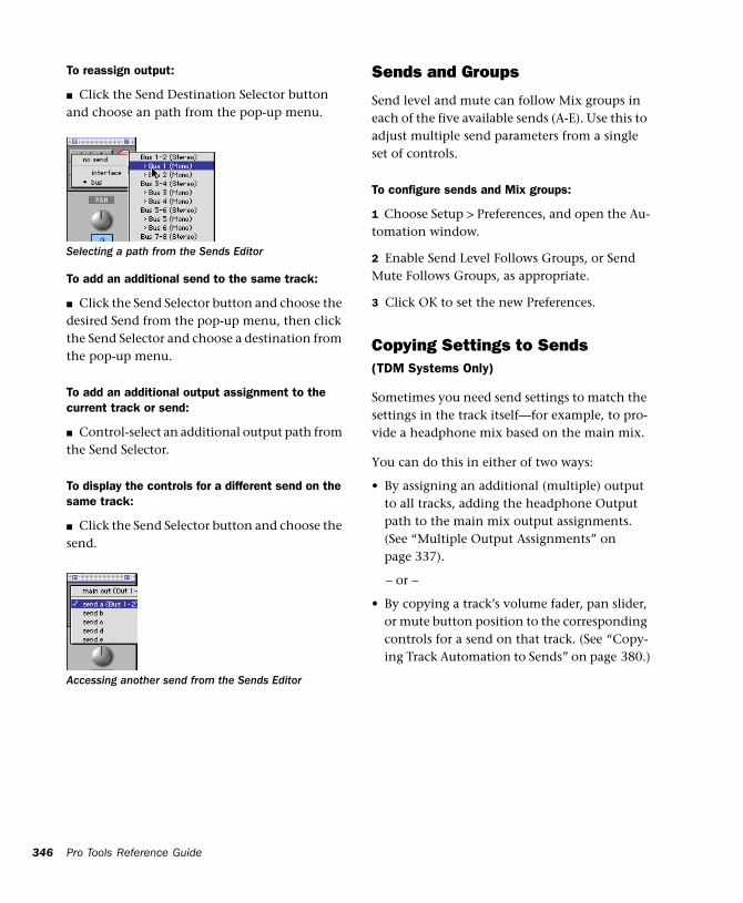
346
To reassign output:
■ Click the Send Destination Selector button and choose an path from the pop-up menu.
To add an additional send to the same track:
■ Click the Send Selector button and choose the desired Send from the pop-up menu, then click the Send Selector and choose a destination from the pop-up menu.
To add an additional output assignment to the current track or send:
■ Control-select an additional output path from the Send Selector.
To display the controls for a different send on the same track:
■ Click the Send Selector button and choose the send.
Selecting a path from the Sends Editor
Accessing another send from the Sends Editor
Pro Tools Reference Guide
Sends and Groups
Send level and mute can follow Mix groups in each of the five available sends (A-E). Use this to adjust multiple send parameters from a single set of controls.
To configure sends and Mix groups:
1 Choose Setup > Preferences, and open the Au-tomation window.
2 Enable Send Level Follows Groups, or Send Mute Follows Groups, as appropriate.
3 Click OK to set the new Preferences.
Copying Settings to Sends(TDM Systems Only)
Sometimes you need send settings to match the settings in the track itself—for example, to pro-vide a headphone mix based on the main mix.
You can do this in either of two ways:
• By assigning an additional (multiple) output to all tracks, adding the headphone Output path to the main mix output assignments. (See “Multiple Output Assignments” on page 337).
– or –
• By copying a track’s volume fader, pan slider, or mute button position to the corresponding controls for a send on that track. (See “Copy-ing Track Automation to Sends” on page 380.)
Submixing for Signal Routing and Effects ProcessingThe bussing and mixing features in Pro Tools support a nearly infinite number of possibilities for submixing and signal routing.
These include:
• Creating inputs for MIDI devices and other audio sources, to monitor or record in Pro Tools.
• Control and automate any submix from a sin-gle fader and channel strip.
• Apply real-time plug-ins or an external pro-cessor to the submix, using the Auxiliary In-put as an effects return
Audio Input from MIDI and Other External Source
You can use an Auxiliary Input to bring an exter-nal audio source such as MIDI devices, tape, mi-crophone inputs, and instruments, into a Pro Tools mix.
To use Auxiliary Inputs to bring external audio sources into a mix:
1 Connect the audio outputs of your MIDI and other external devices to available inputs on your Pro Tools audio interfaces.
2 If necessary, configure the I/O Setup dialog for the input paths you plan to utilize. The I/O Setup dialog configuration determines the choices available for track and sends, inputs, busses, and hardware inserts. (For more infor-mation, see Chapter 7, “I/O Setup.”)
3 Choose File > New Track and choose the type of Auxiliary Input (mono, stereo, or multi-chan-nel on supported systems) from the Track For-mat Selector, then click Create.
4 Set the input of the Auxiliary Input track to the appropriate input path.
5 Assign the track output to the appropriate path, or paths. (See “Multiple Output Assign-ments” on page 337 for more information.)
6 Adjust the Auxiliary Input fader to control the track, and any assigned post-fader send levels.
Mixing Audio Input from MIDI and External Sources
By mixing MIDI and other audio sources through Pro Tools, you can apply mix automa-tion to the volume, pan, mute, send level, send pan, send mute, and plug-in controls of the Auxiliary Input.
Auxiliary Inputs can be routed to audio tracks through internal send busses, or using their track output, to record them to disk.
Using plug-ins, inserts, and sends on Auxiliary Inputs, you can process instruments and other inputs with real-time plug-ins, or external de-vices. See“Send and Return Submixing for Ef-fects Processing” on page 348.
Creating a Submix
Audio is routed to a submix by assigning any combination of sends and track outputs to avail-able bus or output paths.
Auxiliary Inputs serve as effects returns by in-serting plug-ins or external effects processors.
For example, if a stereo sampler was connected to Inputs 1-2, a stereo Auxiliary Input assigned to the Input 1-2 path could monitor the sampler through Pro Tools. You can process the track with plug-ins, or send to a bus path for addi-
Chapter 26: Basic Mixing 347
348
tional processing, or recording. Auxiliary Inputs and Master Faders provide consolidated level control, processing, signal routing, and automa-tion.
Submixing with Track Outputs or Sends
You can use both track outputs and sends to route audio for submixing, depending on whether you want a discrete or send and return submix.
Discrete Submix Output
Discrete submix output means source audio is routed discretely through the submix. This is preferred for dither or other mastering process-ing, where you do not want unprocessed audio heard in addition to the processed signals. Use track outputs (not sends) to assign tracks to a bus path for discrete submixing. In this arrange-ment, the balance of processed and unprocessed signal is controlled by plug-in wet/dry settings.
To create a discrete submix:
1 Choose File > New Track and choose Auxiliary Input (stereo) from the pop-up menu.
2 Set the output of the tracks you want to in-clude in the submix to a stereo bus path.
3 Pan each track.
4 Set the input of the Auxiliary Input to the same bus path to which you assigned all con-tributing tracks.
5 Set the output of the Auxiliary Input track to your main stereo mix outputs (typically, outputs 1–2).
6 Set the Auxiliary Input Track level.
7 To process the submix, assign a plug-in or hardware insert on the Auxiliary Input.
Pro Tools Reference Guide
8 Set the parameters of the plug-in. The plug-in Bypass and Wet/Dry controls (if available) deter-mine the amount of effect heard. (For another way to submix effects, see “To create an effects return submix:” on page 348.)
The contributing track faders control the bal-ance within the submix. The Auxiliary Input track controls the output levels of all tracks routed to it.
You can apply mix automation to the volume, pan, mute, and send level, send pan, and send mute controls of the Auxiliary Input.
You can also bounce a submix to disk to free up the voices for use by other tracks. See Chapter 29, “Mixdown” for information.
Send and Return Submixing for Effects Processing
When you are submixing for reverb, delay, and similar effects processing, use sends to achieve traditional send/return bussing. You can use a real-time plug-in or a hardware I/O insert as a shared resource for all tracks included in a sub-mix. The wet/dry balance in the mix can be con-trolled using the track faders (dry level) and Auxiliary Input fader (effect return, or wet, level).
To create an effects return submix:
1 Assign a send (mono or stereo) to each source track.
2 Assign each tracks main output to your main mix outputs.
3 Set the send destinations on the source tracks to a mono or stereo bus path. Configure the sends for pre- or post-fader, as needed.
4 Choose File > New Tracks.
5 Create one Stereo (or other format) Auxiliary Input, and click Create.
6 Assign a real-time plug-in, or a hardware in-sert, on the Auxiliary Input.
7 Set the plug-in or external effect to “100% wet,” and configure any other parameters as needed.
8 Click the Input Selector of the Auxiliary Input track and set it to the bus path you assigned to the sends on the source tracks.
9 Click the Output Selector of the Auxiliary In-put track and choose an output path (your main mix, or other output).
Adjust the individual track faders to balance the dry (unprocessed) tracks. The amount of effect is controlled by the level of the Auxiliary Input fader.
Send/return setup for an external device
For convenience, you can configure send lev-els and send mutes to follow Mix Groups. This can simplify set up with large sub-mixes. See “Sends and Groups” on page 346 for more information.
Send to external device
Input set to device’s return
Output set to main mix outs 1-2
Controls level of dry signal
Controls level of effect
Creating a Master Send Level Control
Master Fader can control the overall level of bus and output paths.
To create a Master send level control:
1 Choose File > New Track and create a Master Fader in the appropriate mono, stereo, or multi-channel format.
2 Do one of the following:
◆ Set the output of the Master Fader to the same path that you are using to send to an Auxiliary Input track.
◆ Set the output of the Master Fader to match the path that you have chosen for your effects send.
You can then adjust send levels to balance the source tracks, and use the Master Fader as a mas-ter level control for the entire submix.
Soloing Tracks in a Submix
When you want to solo any tracks in a submix, you can solo safe the Auxiliary Input track. This solos tracks that are bussed to the Auxiliary In-put without having to solo the Auxiliary Input as well.
To solo-safe an Auxiliary Input:
■ Command-click (Macintosh) or Control-click (Windows) the Solo button on the Auxiliary In-put track.
See Chapter 27, “Plug-Ins and Inserts” for more information.
Chapter 26: Basic Mixing 349
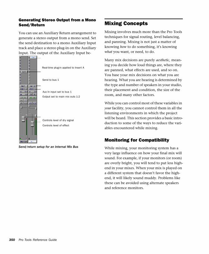
350
Generating Stereo Output from a Mono Send/Return
You can use an Auxiliary Return arrangement to generate a stereo output from a mono send. Set the send destination to a mono Auxiliary Input track and place a stereo plug-in on the Auxiliary Input. The output of the Auxiliary Input be-comes stereo.
Send/return setup for an Internal Mix Bus
Real-time plug-in applied to Insert A
Send to bus 1
Aux In input set to bus 1
Output set to main mix outs 1-2
Controls level of dry signal
Controls level of effect
Pro Tools Reference Guide
Mixing ConceptsMixing involves much more than the Pro Tools techniques for signal routing, level balancing, and panning. Mixing is not just a matter of knowing how to do something, it’s knowing what you want, or need, to do.
Many mix decisions are purely aesthetic, mean-ing you decide how loud things are, where they are panned, what effects are used, and so on. You base your mix decisions on what you are hearing. What you are hearing is determined by the type and number of speakers in your studio, their placement and condition, the size of the room, and many other factors.
While you can control most of these variables in your facility, you cannot control them in all the listening environments in which the project will be heard. This section provides a basic intro-duction to some of the ways to reduce the vari-ables encountered while mixing.
Monitoring for Compatibility
While mixing, your monitoring system has a very large influence on how your final mix will sound. For example, if your monitors (or room) are overly bright, you will tend to put less high-end in your mixes. When your mix is played on a different system that doesn’t favor the high-end, it will likely sound muddy. Problems like these can be avoided using alternate speakers and reference monitors.
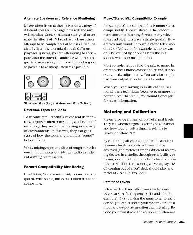
Alternate Speakers and Reference Monitoring
Mixers often listen to their mixes on a variety of different speakers, to gauge how well the mix will translate. Some speakers are designed to em-ulate the effects of TV broadcast, where others attempt to be completely flat across all frequen-cies. By listening to a mix through different playback systems, you are attempting to antici-pate what the intended audience will hear. The goal is to make sure your mix will sound as good as possible to as many listeners as possible.
Reference Tapes and Discs
To become familiar with a studio and its moni-tors, engineers often bring along a collection of recordings they are familiar hearing in a variety of environments. In this way, they can get a sense of how the room and monitors “sound” before mixing.
While mixing, tapes and discs of rough mixes let you audition mixes outside the studio in differ-ent listening environments.
Format Compatibility Monitoring
In addition, format compatibility is sometimes re-quired. With stereo, mixes must often be mono-compatible.
Studio monitors (top) and street monitors (bottom)
Mono/Stereo Mix Compatibility Example
An example of mix compatibility is mono-stereo compatibility. Though stereo is the predomi-nant consumer listening format, many televi-sions and older cars have a single speaker. How a stereo mix sounds through a mono television or radio (AM radio, for example, is mono) can only be verified by checking how the mix sounds when summed to mono.
Most consoles let you fold the mix to mono in order to check mono-compatibility and, if nec-essary, make adjustments. You can also simply pan your output mix channels to center.
When you start mixing in multi-channel sur-round, these techniques becomes even more im-portant, See Chapter 30, “Surround Concepts” for more information.
Metering and Calibration
Meters provide a visual display of signal levels. They tell whether signal is getting to a channel, and how loud or soft a signal is relative to (above or below) “0”.
By calibrating all your equipment to standard reference levels, a consistent level can be achieved (and metered) among different record-ing devices in a studio, throughout a facility, or throughout an entire production chain of a fea-ture-length film. For example, a level of, say, -18 dB coming out of a DAT deck should play and meter at -18 dB in Pro Tools.
Reference Levels
Reference levels are often tones such as sine waves, at specific frequencies (1k and 10k, for example). By supplying the same tones to each device, you can calibrate your systems for equal input and output attenuation and metering. Be-yond your own studio and equipment, reference
Chapter 26: Basic Mixing 351
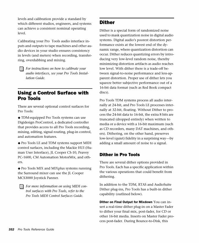
352
levels and calibration provide a standard by which different studios, engineers, and systems can achieve a consistent nominal operating level.
Calibrating your Pro Tools audio interface in-puts and outputs to tape machines and other au-dio devices in your studio ensures consistency in levels (and meters) when recording, transfer-ring, overdubbing and mixing.
Using a Control Surface with Pro ToolsThere are several optional control surfaces for Pro Tools:
◆ TDM-equipped Pro Tools systems can use Digidesign ProControl, a dedicated controller that provides access to all Pro Tools recording, mixing, editing, signal routing, plug-in control, and automation features.
◆ Pro Tools LE and TDM systems support MIDI control surfaces, including the Mackie HUI (Hu-man User Interface), JL Cooper CS-10, Peavey PC-1600, CM Automation MotorMix, and oth-ers.
◆ Pro Tools MIX and MIXplus systems running the Surround mixer can use the JL Cooper MCS3000 Joystick Panner.
For instructions on how to calibrate your audio interfaces, see your Pro Tools Instal-lation Guide.
For more information on using MIDI con-trol surfaces with Pro Tools, refer to the Pro Tools MIDI Control Surfaces Guide.
Pro Tools Reference Guide
DitherDither is a special form of randomized noise used to mask quantization noise in digital audio systems. Digital audio’s poorest distortion per-formance exists at the lowest end of the dy-namic range, where quantization distortion can occur. Dither reduces quantizing errors by intro-ducing very low-level random noise, thereby minimizing distortion artifacts as audio reaches low level. With dither there is a trade-off be-tween signal-to-noise performance and less-ap-parent distortion. Proper use of dither lets you squeeze better subjective performance out of a 16-bit data format (such as Red Book compact discs).
Pro Tools TDM systems process all audio inter-nally at 24-bit, and Pro Tools LE processes inter-nally at 32-bit, floating. Without Dither to pro-cess the 24-bit data to 16-bit, the extra 8 bits are truncated (dropped entirely) when written to media or a device with a 16-bit maximum (such as CD recorders, many DAT machines, and oth-ers). Dithering, on the other hand, preserves low-level (quiet) fidelity in a surprising way—by adding a small amount of noise to a signal.
Dither in Pro Tools
There are several dither options provided in Pro Tools. Each has a specific application within the various operations that could benefit from dithering.
In addition to the TDM, RTAS and AudioSuite Dither plug-ins, Pro Tools has a built-in dither capability (outlined below).
Dither on Final Output for Mixdown You can in-sert a real-time dither plug-in on a Master Fader to dither your final mix, post-fader, for CD or other 16-bit media. Inserts on Master Fader pro-cess post-fader. During Bounce-to-Disk, this
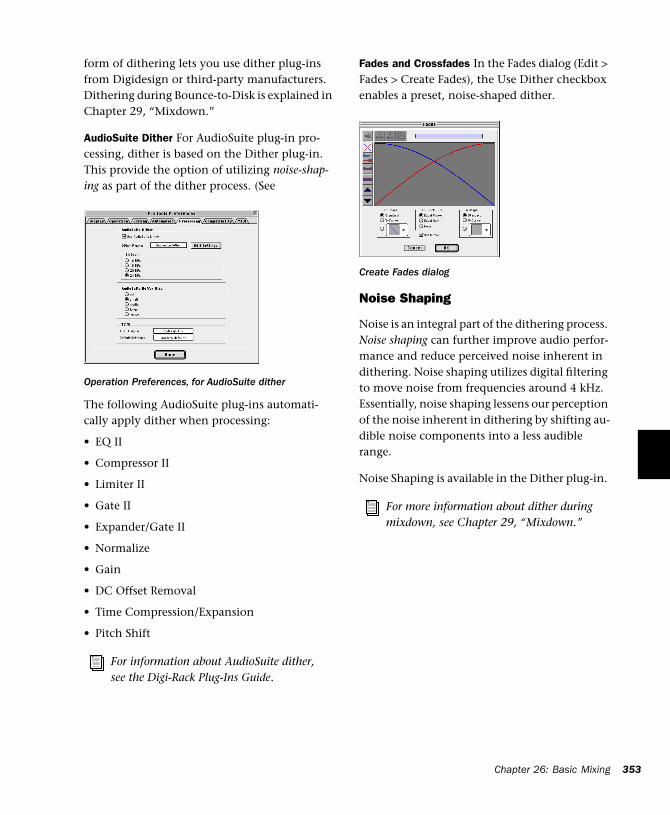
form of dithering lets you use dither plug-ins from Digidesign or third-party manufacturers. Dithering during Bounce-to-Disk is explained in Chapter 29, “Mixdown.”
AudioSuite Dither For AudioSuite plug-in pro-cessing, dither is based on the Dither plug-in. This provide the option of utilizing noise-shap-ing as part of the dither process. (See
The following AudioSuite plug-ins automati-cally apply dither when processing:
• EQ II
• Compressor II
• Limiter II
• Gate II
• Expander/Gate II
• Normalize
• Gain
• DC Offset Removal
• Time Compression/Expansion
• Pitch Shift
Operation Preferences, for AudioSuite dither
For information about AudioSuite dither, see the Digi-Rack Plug-Ins Guide.
Fades and Crossfades In the Fades dialog (Edit > Fades > Create Fades), the Use Dither checkbox enables a preset, noise-shaped dither.
Noise Shaping
Noise is an integral part of the dithering process. Noise shaping can further improve audio perfor-mance and reduce perceived noise inherent in dithering. Noise shaping utilizes digital filtering to move noise from frequencies around 4 kHz. Essentially, noise shaping lessens our perception of the noise inherent in dithering by shifting au-dible noise components into a less audible range.
Noise Shaping is available in the Dither plug-in.
Create Fades dialog
For more information about dither during mixdown, see Chapter 29, “Mixdown.”
Chapter 26: Basic Mixing 353

354
Pro Tools Reference Guide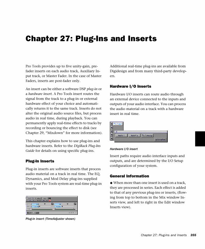
Chapter 27: Plug-Ins and Inserts
Pro Tools provides up to five unity-gain, pre-fader inserts on each audio track, Auxiliary In-put track, or Master Fader. In the case of Master Faders, inserts are post-fader only.
An insert can be either a software DSP plug-in or a hardware insert. A Pro Tools insert routes the signal from the track to a plug-in or external hardware effect of your choice and automati-cally returns it to the same track. Inserts do not alter the original audio source files, but process audio in real time, during playback. You can permanently apply real-time effects to tracks by recording or bouncing the effect to disk (see Chapter 29, “Mixdown” for more information).
This chapter explains how to use plug-ins and hardware inserts. Refer to the DigiRack Plug-Ins Guide for details on using specific plug-ins.
Plug-In Inserts
Plug-in inserts are software inserts that process audio material on a track in real time. The EQ, Dynamics, and Mod Delay plug-ins supplied with your Pro Tools system are real-time plug-in inserts.
Plug-in insert (TimeAdjuster shown)
Additional real-time plug-ins are available from Digidesign and from many third-party develop-ers.
Hardware I/O Inserts
Hardware I/O inserts can route audio through an external device connected to the inputs and outputs of your audio interface. You can process the audio material on a track with a hardware insert in real time.
Insert paths require audio interface inputs and outputs, and are determined by the I/O Setup configuration of your system.
General Information
◆ When more than one insert is used on a track, they are processed in series. Each effect is added to that of any previous plug-ins or inserts, (flow-ing from top to bottom in the Mix window In-serts view, and left to right in the Edit window Inserts view).
Hardware I/O insert
Chapter 27: Plug-Ins and Inserts 355
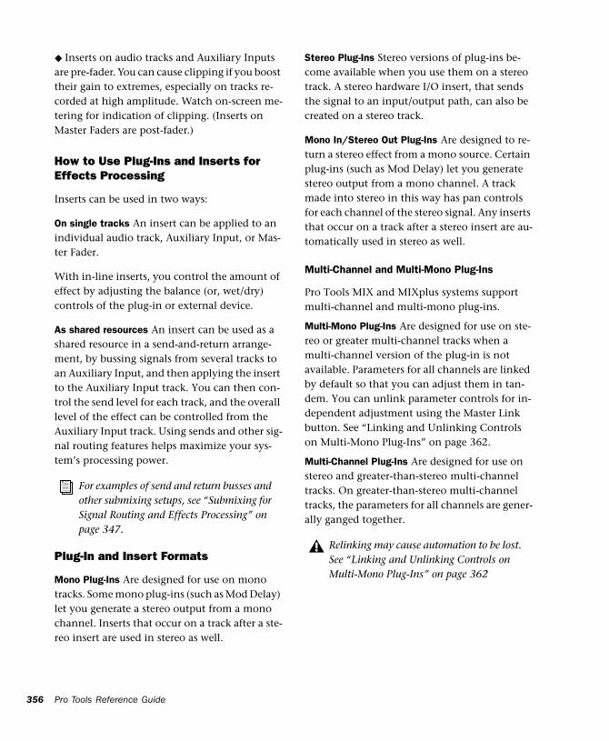
356
◆ Inserts on audio tracks and Auxiliary Inputs are pre-fader. You can cause clipping if you boost their gain to extremes, especially on tracks re-corded at high amplitude. Watch on-screen me-tering for indication of clipping. (Inserts on Master Faders are post-fader.)
How to Use Plug-Ins and Inserts for Effects Processing
Inserts can be used in two ways:
On single tracks An insert can be applied to an individual audio track, Auxiliary Input, or Mas-ter Fader.
With in-line inserts, you control the amount of effect by adjusting the balance (or, wet/dry) controls of the plug-in or external device.
As shared resources An insert can be used as a shared resource in a send-and-return arrange-ment, by bussing signals from several tracks to an Auxiliary Input, and then applying the insert to the Auxiliary Input track. You can then con-trol the send level for each track, and the overall level of the effect can be controlled from the Auxiliary Input track. Using sends and other sig-nal routing features helps maximize your sys-tem’s processing power.
Plug-In and Insert Formats
Mono Plug-Ins Are designed for use on mono tracks. Some mono plug-ins (such as Mod Delay) let you generate a stereo output from a mono channel. Inserts that occur on a track after a ste-reo insert are used in stereo as well.
For examples of send and return busses and other submixing setups, see “Submixing for Signal Routing and Effects Processing” on page 347.
Pro Tools Reference Guide
Stereo Plug-Ins Stereo versions of plug-ins be-come available when you use them on a stereo track. A stereo hardware I/O insert, that sends the signal to an input/output path, can also be created on a stereo track.
Mono In/Stereo Out Plug-Ins Are designed to re-turn a stereo effect from a mono source. Certain plug-ins (such as Mod Delay) let you generate stereo output from a mono channel. A track made into stereo in this way has pan controls for each channel of the stereo signal. Any inserts that occur on a track after a stereo insert are au-tomatically used in stereo as well.
Multi-Channel and Multi-Mono Plug-Ins
Pro Tools MIX and MIXplus systems support multi-channel and multi-mono plug-ins.
Multi-Mono Plug-Ins Are designed for use on ste-reo or greater multi-channel tracks when a multi-channel version of the plug-in is not available. Parameters for all channels are linked by default so that you can adjust them in tan-dem. You can unlink parameter controls for in-dependent adjustment using the Master Link button. See “Linking and Unlinking Controls on Multi-Mono Plug-Ins” on page 362.
Multi-Channel Plug-Ins Are designed for use on stereo and greater-than-stereo multi-channel tracks. On greater-than-stereo multi-channel tracks, the parameters for all channels are gener-ally ganged together.
Relinking may cause automation to be lost. See “Linking and Unlinking Controls on Multi-Mono Plug-Ins” on page 362
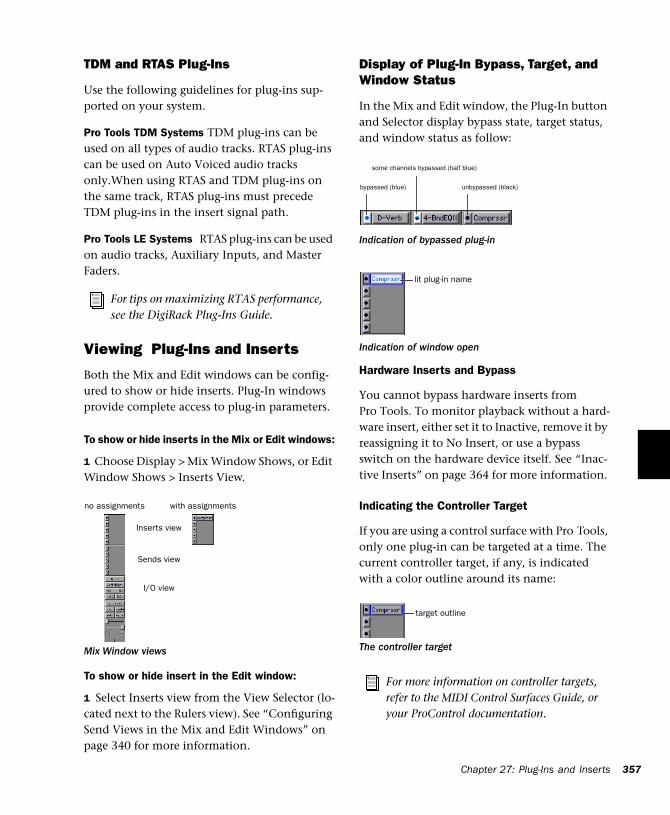
TDM and RTAS Plug-Ins
Use the following guidelines for plug-ins sup-ported on your system.
Pro Tools TDM Systems TDM plug-ins can be used on all types of audio tracks. RTAS plug-ins can be used on Auto Voiced audio tracks only.When using RTAS and TDM plug-ins on the same track, RTAS plug-ins must precede TDM plug-ins in the insert signal path.
Pro Tools LE Systems RTAS plug-ins can be used on audio tracks, Auxiliary Inputs, and Master Faders.
Viewing Plug-Ins and Inserts
Both the Mix and Edit windows can be config-ured to show or hide inserts. Plug-In windows provide complete access to plug-in parameters.
To show or hide inserts in the Mix or Edit windows:
1 Choose Display > Mix Window Shows, or Edit Window Shows > Inserts View.
To show or hide insert in the Edit window:
1 Select Inserts view from the View Selector (lo-cated next to the Rulers view). See “Configuring Send Views in the Mix and Edit Windows” on page 340 for more information.
For tips on maximizing RTAS performance, see the DigiRack Plug-Ins Guide.
Mix Window views
Inserts view
Sends view
I/O view
with assignmentsno assignments
Display of Plug-In Bypass, Target, and Window Status
In the Mix and Edit window, the Plug-In button and Selector display bypass state, target status, and window status as follow:
Hardware Inserts and Bypass
You cannot bypass hardware inserts from Pro Tools. To monitor playback without a hard-ware insert, either set it to Inactive, remove it by reassigning it to No Insert, or use a bypass switch on the hardware device itself. See “Inac-tive Inserts” on page 364 for more information.
Indicating the Controller Target
If you are using a control surface with Pro Tools, only one plug-in can be targeted at a time. The current controller target, if any, is indicated with a color outline around its name:
Indication of bypassed plug-in
Indication of window open
The controller target
For more information on controller targets, refer to the MIDI Control Surfaces Guide, or your ProControl documentation.
bypassed (blue)
some channels bypassed (half blue)
unbypassed (black)
lit plug-in name
target outline
Chapter 27: Plug-Ins and Inserts 357
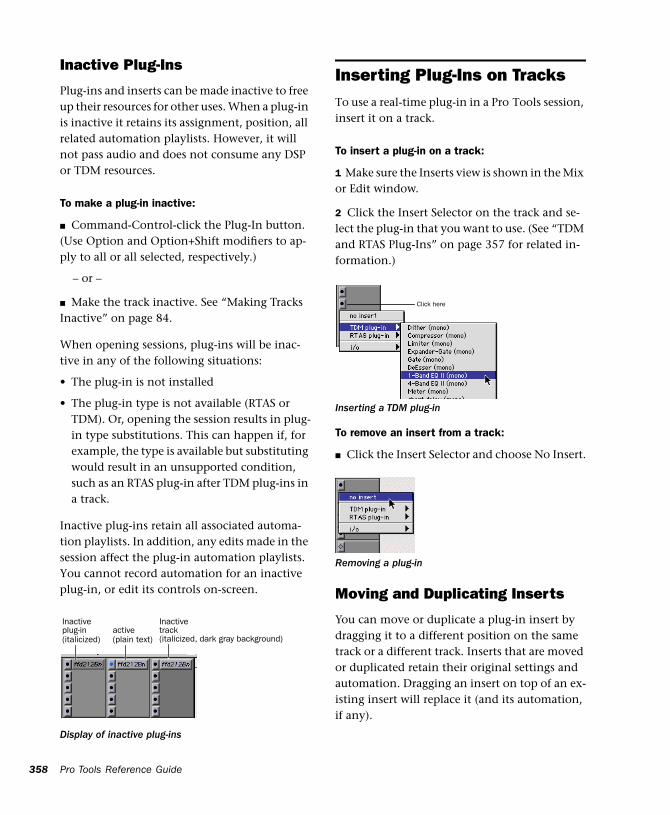
358
Inactive Plug-Ins
Plug-ins and inserts can be made inactive to free up their resources for other uses. When a plug-in is inactive it retains its assignment, position, all related automation playlists. However, it will not pass audio and does not consume any DSP or TDM resources.
To make a plug-in inactive:
■ Command-Control-click the Plug-In button. (Use Option and Option+Shift modifiers to ap-ply to all or all selected, respectively.)
– or –
■ Make the track inactive. See “Making Tracks Inactive” on page 84.
When opening sessions, plug-ins will be inac-tive in any of the following situations:
• The plug-in is not installed
• The plug-in type is not available (RTAS or TDM). Or, opening the session results in plug-in type substitutions. This can happen if, for example, the type is available but substituting would result in an unsupported condition, such as an RTAS plug-in after TDM plug-ins in a track.
Inactive plug-ins retain all associated automa-tion playlists. In addition, any edits made in the session affect the plug-in automation playlists. You cannot record automation for an inactive plug-in, or edit its controls on-screen.
Display of inactive plug-ins
Inactive
(italicized)active (plain text)
Inactive
(italicized, dark gray background)plug-in track
Pro Tools Reference Guide
Inserting Plug-Ins on TracksTo use a real-time plug-in in a Pro Tools session, insert it on a track.
To insert a plug-in on a track:
1 Make sure the Inserts view is shown in the Mix or Edit window.
2 Click the Insert Selector on the track and se-lect the plug-in that you want to use. (See “TDM and RTAS Plug-Ins” on page 357 for related in-formation.)
To remove an insert from a track:
■ Click the Insert Selector and choose No Insert.
Moving and Duplicating Inserts
You can move or duplicate a plug-in insert by dragging it to a different position on the same track or a different track. Inserts that are moved or duplicated retain their original settings and automation. Dragging an insert on top of an ex-isting insert will replace it (and its automation, if any).
Inserting a TDM plug-in
Removing a plug-in
Click here
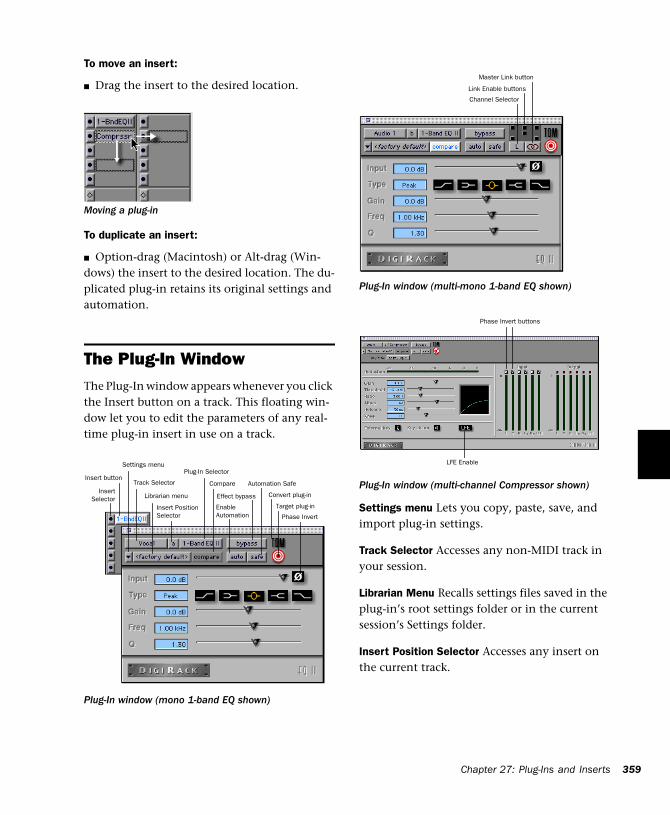
To move an insert:
■ Drag the insert to the desired location.
To duplicate an insert:
■ Option-drag (Macintosh) or Alt-drag (Win-dows) the insert to the desired location. The du-plicated plug-in retains its original settings and automation.
The Plug-In WindowThe Plug-In window appears whenever you click the Insert button on a track. This floating win-dow let you to edit the parameters of any real-time plug-in insert in use on a track.
Moving a plug-in
Plug-In window (mono 1-band EQ shown)
InsertSelector
Settings menu
Track Selector
Librarian menu
Insert PositionSelector
Plug-In Selector
Effect bypass
Compare
EnableAutomation
Insert buttonAutomation Safe
Convert plug-in
Target plug-in
Phase Invert
Settings menu Lets you copy, paste, save, and import plug-in settings.Track Selector Accesses any non-MIDI track in your session.
Librarian Menu Recalls settings files saved in the plug-in’s root settings folder or in the current session’s Settings folder.
Insert Position Selector Accesses any insert on the current track.
Plug-In window (multi-mono 1-band EQ shown)
Plug-In window (multi-channel Compressor shown)
Channel Selector
Link Enable buttons
Master Link button
LFE Enable
Phase Invert buttons
C
h apter 27: Plug-Ins and Inserts 359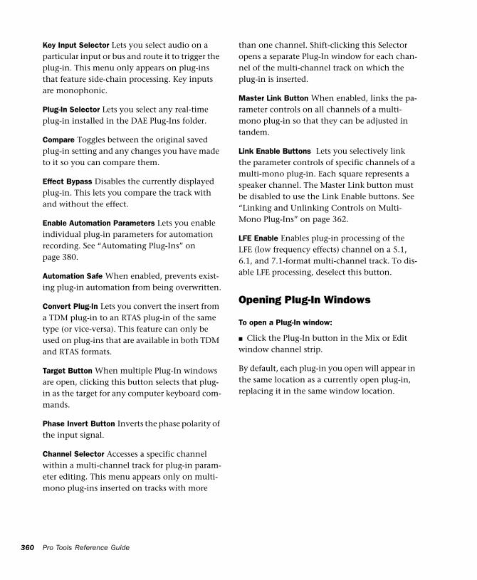
360
Key Input Selector Lets you select audio on a particular input or bus and route it to trigger the plug-in. This menu only appears on plug-ins that feature side-chain processing. Key inputs are monophonic.
Plug-In Selector Lets you select any real-time plug-in installed in the DAE Plug-Ins folder.
Compare Toggles between the original saved plug-in setting and any changes you have made to it so you can compare them.
Effect Bypass Disables the currently displayed plug-in. This lets you compare the track with and without the effect.
Enable Automation Parameters Lets you enable individual plug-in parameters for automation recording. See “Automating Plug-Ins” on page 380.
Automation Safe When enabled, prevents exist-ing plug-in automation from being overwritten.
Convert Plug-In Lets you convert the insert from a TDM plug-in to an RTAS plug-in of the same type (or vice-versa). This feature can only be used on plug-ins that are available in both TDM and RTAS formats.
Target Button When multiple Plug-In windows are open, clicking this button selects that plug-in as the target for any computer keyboard com-mands.
Phase Invert Button Inverts the phase polarity of the input signal.
Channel Selector Accesses a specific channel within a multi-channel track for plug-in param-eter editing. This menu appears only on multi-mono plug-ins inserted on tracks with more
Pro Tools Reference Guide
than one channel. Shift-clicking this Selector opens a separate Plug-In window for each chan-nel of the multi-channel track on which the plug-in is inserted.
Master Link Button When enabled, links the pa-rameter controls on all channels of a multi-mono plug-in so that they can be adjusted in tandem.
Link Enable Buttons Lets you selectively link the parameter controls of specific channels of a multi-mono plug-in. Each square represents a speaker channel. The Master Link button must be disabled to use the Link Enable buttons. See “Linking and Unlinking Controls on Multi-Mono Plug-Ins” on page 362.
LFE Enable Enables plug-in processing of the LFE (low frequency effects) channel on a 5.1, 6.1, and 7.1-format multi-channel track. To dis-able LFE processing, deselect this button.
Opening Plug-In Windows
To open a Plug-In window:
■ Click the Plug-In button in the Mix or Edit window channel strip.
By default, each plug-in you open will appear in the same location as a currently open plug-in, replacing it in the same window location.
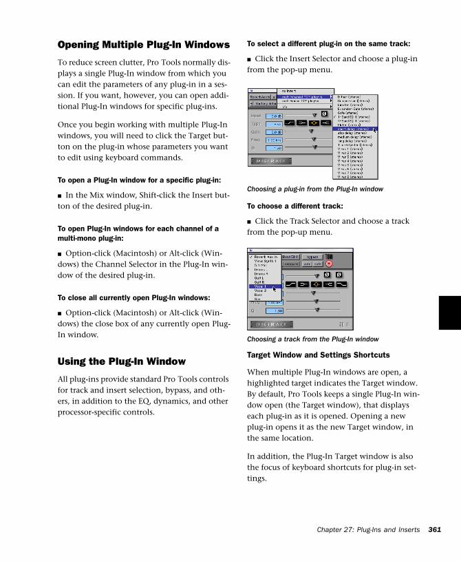
Opening Multiple Plug-In Windows
To reduce screen clutter, Pro Tools normally dis-plays a single Plug-In window from which you can edit the parameters of any plug-in in a ses-sion. If you want, however, you can open addi-tional Plug-In windows for specific plug-ins.
Once you begin working with multiple Plug-In windows, you will need to click the Target but-ton on the plug-in whose parameters you want to edit using keyboard commands.
To open a Plug-In window for a specific plug-in:
■ In the Mix window, Shift-click the Insert but-ton of the desired plug-in.
To open Plug-In windows for each channel of a multi-mono plug-in:
■ Option-click (Macintosh) or Alt-click (Win-dows) the Channel Selector in the Plug-In win-dow of the desired plug-in.
To close all currently open Plug-In windows:
■ Option-click (Macintosh) or Alt-click (Win-dows) the close box of any currently open Plug-In window.
Using the Plug-In Window
All plug-ins provide standard Pro Tools controls for track and insert selection, bypass, and oth-ers, in addition to the EQ, dynamics, and other processor-specific controls.
To select a different plug-in on the same track:
■ Click the Insert Selector and choose a plug-in from the pop-up menu.
To choose a different track:
■ Click the Track Selector and choose a track from the pop-up menu.
Target Window and Settings Shortcuts
When multiple Plug-In windows are open, a highlighted target indicates the Target window. By default, Pro Tools keeps a single Plug-In win-dow open (the Target window), that displays each plug-in as it is opened. Opening a new plug-in opens it as the new Target window, in the same location.
In addition, the Plug-In Target window is also the focus of keyboard shortcuts for plug-in set-tings.
Choosing a plug-in from the Plug-In window
Choosing a track from the Plug-In window
Chapter 27: Plug-Ins and Inserts 361
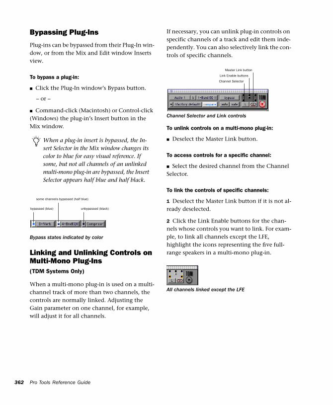
362
Bypassing Plug-Ins
Plug-ins can be bypassed from their Plug-In win-dow, or from the Mix and Edit window Inserts view.
To bypass a plug-in:
■ Click the Plug-In window’s Bypass button.
– or –
■ Command-click (Macintosh) or Control-click (Windows) the plug-in’s Insert button in the Mix window.
Linking and Unlinking Controls on Multi-Mono Plug-Ins(TDM Systems Only)
When a multi-mono plug-in is used on a multi-channel track of more than two channels, the controls are normally linked. Adjusting the Gain parameter on one channel, for example, will adjust it for all channels.
When a plug-in insert is bypassed, the In-sert Selector in the Mix window changes its color to blue for easy visual reference. If some, but not all channels of an unlinked multi-mono plug-in are bypassed, the Insert Selector appears half blue and half black.
Bypass states indicated by color
bypassed (blue)
some channels bypassed (half blue)
unbypassed (black)
Pro Tools Reference Guide
If necessary, you can unlink plug-in controls on specific channels of a track and edit them inde-pendently. You can also selectively link the con-trols of specific channels.
To unlink controls on a multi-mono plug-in:
■ Deselect the Master Link button.
To access controls for a specific channel:
■ Select the desired channel from the Channel Selector.
To link the controls of specific channels:
1 Deselect the Master Link button if it is not al-ready deselected.
2 Click the Link Enable buttons for the chan-nels whose controls you want to link. For exam-ple, to link all channels except the LFE, highlight the icons representing the five full-range speakers in a multi-mono plug-in.
Channel Selector and Link controls
All channels linked except the LFE
Channel Selector
Link Enable buttons
Master Link button
Editing Plug-In Parameters
You can edit plug-in parameters by dragging the parameter’s slider or by typing a value into the parameter’s text box. See the DigiRack Plug-Ins Guide for complete instructions.
To edit a plug-in parameter:
1 Begin audio playback so that you can hear pa-rameter changes in real time.
2 Adjust the parameters of the plug-in for the ef-fect you want.
Keyboard Shortcuts
■ For finer adjustments, Command-drag (Mac-intosh) or Control-drag (Windows) the control.
■ To return a control to its default value, Op-tion-click (Macintosh) or Alt-click (Windows) the control.
Keyboard Input for Plug-In Parameters
You can use your computer keyboard to edit plug-in parameters.
If multiple Plug-In windows are open, Tab and keyboard entry remain focussed on the plug-in that is the Target window.
To edit parameters with a keyboard:
◆ Click in the parameter text field that you want to edit to activate the field. Type the desired value.
◆ In fields that support values in kilohertz, typ-ing “k” after a number value will multiply the value by 1000. If you want to enter a value of 8000, type “8k”.
◆ To increase a value, press the Up Arrow on your keyboard. To decrease a value, press the Down Arrow on your keyboard.
◆ Press Enter on the numeric keyboard after typ-ing a value to input the value (without leaving the selected parameter field).
◆ Press Return (Macintosh) or Enter on the al-pha keyboard (Windows) to enter the value and leave keyboard editing mode.
◆ To move downward through the different pa-rameter fields, press the Tab key. To move up-wards, press Shift-Tab.
Plug-In Automation and Safe
All real-time plug-ins can be fully automated, and support all Pro Tools automation modes (Write, Touch, and Latch, plus Trim).
The Auto button opens the Enable Automation Parameters dialog, where you can enable indi-vidual plug-in parameters for automation re-cording. See Chapter 28, “Automation” for more information on this feature and shortcuts to enable plug-in parameter.
The Safe button engages Automation Safe mode. When enabled, existing plug-in automation is protected from being overwritten. (See “Auto-mating Plug-Ins” on page 380 for more informa-tion.)
Chapter 27: Plug-Ins and Inserts 363
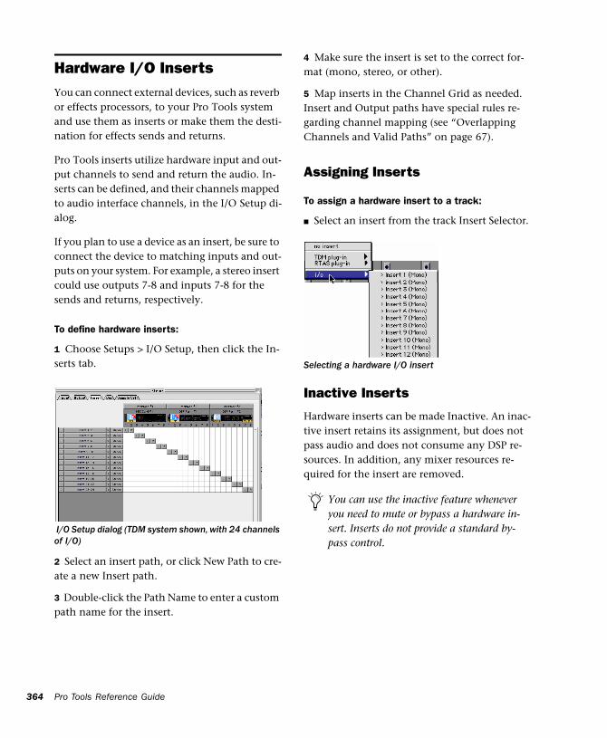
364
Hardware I/O InsertsYou can connect external devices, such as reverb or effects processors, to your Pro Tools system and use them as inserts or make them the desti-nation for effects sends and returns.
Pro Tools inserts utilize hardware input and out-put channels to send and return the audio. In-serts can be defined, and their channels mapped to audio interface channels, in the I/O Setup di-alog.
If you plan to use a device as an insert, be sure to connect the device to matching inputs and out-puts on your system. For example, a stereo insert could use outputs 7-8 and inputs 7-8 for the sends and returns, respectively.
To define hardware inserts:
1 Choose Setups > I/O Setup, then click the In-serts tab.
2 Select an insert path, or click New Path to cre-ate a new Insert path.
3 Double-click the Path Name to enter a custom path name for the insert.
I/O Setup dialog (TDM system shown, with 24 channels of I/O)
Pro Tools Reference Guide
4 Make sure the insert is set to the correct for-mat (mono, stereo, or other).
5 Map inserts in the Channel Grid as needed. Insert and Output paths have special rules re-garding channel mapping (see “Overlapping Channels and Valid Paths” on page 67).
Assigning Inserts
To assign a hardware insert to a track:
■ Select an insert from the track Insert Selector.
Inactive Inserts
Hardware inserts can be made Inactive. An inac-tive insert retains its assignment, but does not pass audio and does not consume any DSP re-sources. In addition, any mixer resources re-quired for the insert are removed.
Selecting a hardware I/O insert
You can use the inactive feature whenever you need to mute or bypass a hardware in-sert. Inserts do not provide a standard by-pass control.
To make an insert inactive:
■ Command-Control-click the Insert button. Use the Option and Option+Shift modifiers to apply to all or all selected tracks, respectively.
– or –
■ Make the track inactive (this sets all associated inserts, sends, outputs, and plug-ins inactive).
When opening sessions on a system with insuf-ficient DSP resources, unavailable inserts are au-tomatically set to inactive.
Connecting and Integrating External DevicesPro Tools TDM and Digi 001 systems can create dedicated connections to external analog or dig-ital devices. The number and type of connec-tions depends on what kind of system you have.
You can also use the inputs and outputs of an Audiomedia III card to connect external devices. You can send and return an analog signal using the analog connectors on the card, and monitor through a DAT machine connected to the digi-tal output. You can also send and return a digital signal to an external device that supports digital I/O (such as a reverb unit), and monitor with the analog outputs.
To connect an external device to a Pro Tools system:
1 Connect an unused output (or pair of outputs for a stereo device) of your Pro Tools system to an input of the external signal processor.
2 Connect the output of the external signal pro-cessor to an unused input (or pair of inputs for a stereo device) of your Pro Tools system.
3 Define output, input, or insert paths as appro-priate in the I/O Setup dialog.
If you plan to use a device as an insert, be sure to connect the device to matching inputs and out-puts on your system. For example, a stereo insert could use outputs 7-8 and inputs 7-8 for the sends and returns, respectively.
Connecting Effects Units Digitally
If you want to use the digital inputs and outputs on your Pro Tools system as effects sends and re-turns to a digital effects device, Pro Tools should be the clock master in most cases. Set your digi-tal effects device to accept an external digital clock so that it synchronizes to Pro Tools.
To set up a digital send to an external device from a TDM system:
1 Do one of the following:
◆ On an 888/24 I/O Interface, choose Setups > Hardware, click Other Options, and set the channel pair to Digital.
◆ On an 882/20 I/O or 1622 I/O Interface, choose Setups > Hardware and set Channel 1–2 input to Digital.
2 Choose Internal from the Sync Mode pop-up menu.
3 Click OK.
For details on connecting external devices, refer to the Pro Tools Hardware Installation Guide that came with your system.
Chapter 27: Plug-Ins and Inserts 365
366
To set up a digital send to an external device from a Digi001 system:
1 Choose Setups > Playback Engine and click Other Options.
2 Do one of the following:
◆ If the external device is connected to the S/PDIF RCA jacks, deselect S/PDIF Mirroring. (When S/PDIF Mirroring is on, digital output at the S/PDIF RCA jacks exactly mirrors the output of analog Channels 1–2.)
◆ If the external device is connected to the Op-tical ports, choose a format (most likely S/PDIF for an effects device) from the Optical Format pop-up menu.
3 Choose Internal from the Sync Mode pop-up menu.
4 Click OK.
5 Optionally, configure the I/O Setup dialog with new path names for effects routing.
To set up a digital send to an external device from an Audiomedia III system:
1 Choose Setups > Playback Engine and deselect S/PDIF Mirroring. (When S/PDIF Mirroring is on, digital output at the S/PDIF RCA jacks ex-actly mirrors the output of analog Channels 1–2.)
2 Choose Internal from the Sync Mode pop up menu.
3 Click OK.
4 Optionally, configure the I/O Setup dialog with new path names for effects routing.
If you set the Optical Format to S/PDIF, Pro Tools will watch the Optical port for any audio input on the S/PDIF RCA jacks.
Pro Tools Reference Guide
Using External Clock Sources
Pro Tools can use the digital input on Channels 1–2 as its clock master. To synchronize your sys-tem to an external clock source, connect the ex-ternal source to Pro Tools digital inputs 1–2.
TDM Systems
Pro Tools can receive external clock from Chan-nels 1–2, using either the AES/EBU (on the 888/24 I/O) or S/PDIF connectors on your audio interface. Pro Tools also supports optical sync through an Adat Bridge.
In an expanded TDM system, connect to the digital input on Channels 1–2 of the master au-dio interface. This is the audio interface con-nected to the first MIX or d24 card in your sys-tem.
To select an external clock source for a TDM system:
1 Choose Setups > Hardware.
2 Set the Sync Mode to Digital.
3 Choose the Digital Format for the input.
Digi 001 Systems
Pro Tools can receive external clock from the optical input (on the Digi 001 PCI card) or S/PDIF input (on the Digi 001 I/O box).
To select an external clock source for a Digi 001 system:
1 Choose Setups > Hardware.
2 Set the Sync Mode to match the type of input.
Refer to the Pro Tools TDM System Instal-lation Guide to determine correct card order and audio interface connections for TDM systems.
If you choose Optical, make sure the Optical Format matches the type of optical input you are sending to your Pro Tools system.
Audiomedia III Systems
Pro Tools can receive external clock from the S/PDIF input on the Audiomedia III card.
To select an external clock source for an Audiomedia III system:
1 Choose Setups > Hardware.
2 Set the Sync Mode to match the type of input.
If you set the Optical Format to S/PDIF, Pro Tools will watch the Optical port for ex-ternal clock, and ignore any clock input on the S/PDIF RCA jacks.
Chapter 27: Plug-Ins and Inserts 367

368
Pro Tools Reference Guide
Chapter 28: Automation
Pro Tools features dynamic automation of vol-ume, pan, and mute controls for audio tracks and sends, MIDI tracks, and real-time plug-in parameters. In Pro Tools, you can write automa-tion moves in real time during playback of your session. You can also edit automation data with the same techniques you use to edit audio and MIDI data.
Automation Accuracy with Control Surfaces
ProControl Digidesign’s ProControl supports all automation features in Pro Tools. ProControl DigiFaders™ provide 10-bit accuracy, or 1,024 steps of resolution. Pro Tools interpolates this ProControl input and provides 24-bit resolution of volume and send automation on playback.
MIDI Control Surfaces Most MIDI control sur-faces have 8-bit resolution, or 128 steps; the Mackie HUI has 9-bit resolution, or 512 steps. Pro Tools interpolates this input to a much higher resolution on playback, resulting in fader automation that is smooth enough to satisfy professional requirements.
For details on using ProControl to create mix automation, refer to the ProControl User’s Guide.
Automation Quick StartPro Tools provides many options for recording, replacing, and editing automation data.
The basic steps for automation recording are:
• Enable the automation type that you want to record (volume, pan, mute, send level, send pan, send mute, or plug-in automation).
• Put the appropriate tracks in an automation writing mode (Write, Touch, or Latch, or a Trim mode).
• If you are automating a plug-in, enable the in-dividual plug-in parameters to be automated.
• Automation Safe any plug-ins, outputs, or sends that have existing automation data that you want to protect from being overwritten.
• Begin playback to begin automation record-ing, and adjust controls as needed. Pro Tools remembers all moves performed on enabled parameters.
To edit automation once it has been recorded, you can:
• Repeat the above steps to write new automa-tion over the previous data.
• Graphically edit the automation data in the Edit window.
• Cut, copy, paste, or delete automation data (certain restrictions apply).
Chapter 28: Automation 369
370
Automation PlaylistsEach Pro Tools track contains a single automa-tion playlist for each automatable control.
On audio tracks, these controls include:
• Volume
• Pan
• Mute
• Send volume, pan, and mute
• Plug-in parameters
On MIDI tracks, these controls include:
• Volume
• Pan
• Mute
You can display and edit each of these automat-able parameters individually from Pro Tools, even during playback.
In addition, you can display and edit other con-tinuous MIDI controller data (such as mod wheel, breath controller, foot controller, or sus-tain) in a similar manner. For more information on editing MIDI data, see “Continuous Control-ler Events” on page 301.
Automation Playlists with Audio and MIDI Regions
Pro Tools handles audio regions and automa-tion playlists differently from MIDI regions and automation playlists.
Pro Tools Reference Guide
Audio Tracks
On audio tracks, automation data resides on a separate playlist from audio data and regions. Each edit playlist on an audio track shares the same automation data.
MIDI Tracks
On MIDI tracks, all controller automation data except for Mute data is stored in the MIDI region that contains it. Each edit playlist on a MIDI track is separate, and represents a distinct per-formance, complete with controller automa-tion.
Multiple Edit Playlists and Audio Track Automation
All edit playlists on a single audio track share the same automation data. When you record or edit automation data in an audio track, the automa-tion data is stored in the track automation play-list so it can be edited with, or independently from, its associated audio regions. (MIDI auto-mation data always follows region editing, with the exception of mute. See “MIDI Tracks” on page 370 for more information.)
◆ When you copy or cut audio data from a track while it is in Waveform view, the underlying au-tomation data is cut or copied with it.
◆ If you paste audio data from other locations or tracks into an edit playlist, you may change the underlying automation data on the track.
Mute data is independent of the MIDI data in a MIDI region. This lets you mute play-back of individual MIDI tracks in Pro Tools without altering the controller data.
◆ When you trim audio regions with the Trim tool, or cut, copy, paste, or delete audio regions, underlying automation data is also trimmed, cut, copied, pasted, or deleted.
◆ When you use the Trim command, the under-lying automation data remains, unchanged.
Using Tracks for Playlist Editing
The Duplicate Track command provides a con-venient way to make a working copy of a track to experiment with routing, plug-ins, and auto-mation. This protects original track’s from being edited or overwritten.
To copy a track for editing:
1 Select the track and choose File > Duplicate Track. Duplicate Track create a complete copy of the track, including all routing, plug-ins, and automation.
2 Command-Control-click the Track Type icon, or select that track and choose File > Make Se-lected Tracks Inactive.
3 Begin editing automation and other parame-ters on the duplicated track.
Edit and assembling the track regions before ap-plying automation to them.
For more information, see “Editing Auto-mation” on page 385.
Automation ModesEach track provides an Automation Mode Selec-tor. Automation modes control how a track’s automation data is written and played back.
Auto Off
Auto Off mode turns off automation for all au-tomatable controls:
• Volume
• Pan
• Mute
• Send volume, pan, and mute
• Plug-in parameters
• MIDI volume, pan, and mute
In Auto Off mode, automation data for these pa-rameters is ignored during playback. All other MIDI controller data is sent.
Auto Read
Auto Read mode plays the automation that was previously written for a track.
Auto Write
Auto Write mode writes automation from the time playback starts to the time it stops, erasing any previously written automation for the dura-tion of the automation pass.
After an automation pass, Pro Tools automati-cally switches from Auto Write mode to Auto Touch mode. This prevents you from acciden-tally overwriting automation data on later play-back. On TDM systems, you can turn off this be-havior and remain in Auto Write mode. See “Write Switches To Touch After Pass” on page 374 for details.
Chapter 28: Automation 371
372
Auto Touch
Auto Touch mode writes automation only while a fader or switch is touched or clicked with the mouse. When the fader is released, the writing of automation stops and the fader returns to any previously automated position, at a rate deter-mined by the AutoMatch and Touch Timeout settings. See “Automation Preferences” on page 374.
In Auto Touch mode, certain control surfaces start writing automation as soon as you touch them. These include:
• Touch-sensitive motorized fader controllers, such as Digidesign ProControl, or the Mackie HUI.
• Continuous-belt controllers, such as the Penny & Giles DC16/MM16.
With other control surfaces in Auto Touch mode, writing of automation does not begin un-til the fader hits the pass-through point, or the previously automated position. Once you reach the pass-through point with the fader, writing of automation begins and continues until you stop moving the fader.
Auto Latch
Auto Latch mode works in the same way as Auto Touch mode, writing automation only if you touch or move a control. However, unlike Auto Touch, writing of automation continues until you stop playback. This mode is particularly use-ful for automating pan controls and plug-ins, since it does not time out and revert to its previ-ous position when you release a control.
See also “Writing Automation to the Start, End or All of a Selection” on page 391.
Pro Tools Reference Guide
Trim Mode
(TDM Systems Only)
Pro Tools TDM systems can adjust (or trim) ex-isting track volume and send level automation data in real time. Pan and plug-in automation cannot be trimmed in this manner. Trim mode works in combination with the other automa-tion modes (Auto Read, Auto Touch, Auto Latch, Auto Write) and is useful when you want to preserve all of your volume automation moves, but need to make levels a bit louder or softer to balance a mix.
When editing automation in Trim mode, fader moves write relative rather than absolute values. The existing automation data is changed by the amount of increase or decrease (or the delta value) indicated by the faders. When trimming, a track’s Volume indicator or Send Level indica-tor shows the delta values being written rather than the absolute value.
When Trim mode is enabled, non-trimmable controls behave in the same manner as in the standard automation modes, with the exception of Trim/Auto Write mode, where non-trimma-ble controls operate as in Auto Touch mode.
Trim/Auto Off
Trim/Auto Off mode turns off automation and trimming for a track. All automation moves are ignored during playback.
Trim/Auto Read
In Trim/Auto Read mode, volume and send fad-ers follow the previously written automation. When one of the faders is touched, the trim moves (delta values) are played back, but are not written into the automation data. This lets you audition trim moves without affecting existing automation.
When this mode is enabled, non-trimmable controls (all controls other than track volume and send level) behave as if they are in regular Read mode—no automation data is written.
Trim/Auto Touch
In Trim/Auto Touch mode, when playback be-gins, volume and send faders follow the previ-ously written automation. When one of the fad-ers is touched, real-time trimming begins. Fader moves write delta values (an increase or decrease in existing automation data).
When the fader is released, trimming stops and the fader returns to a zero delta value and con-tinues to follow the previously written automa-tion. The rate of the fader’s return to a zero delta value is determined by the AutoMatch Time specified in the Automation Preferences. See “Automation Preferences” on page 374 for more information.
When this mode is enabled, non-trimmable controls (all controls other than track volume and send level) behave as if they are in regular Auto Touch mode—they follow the previously written automation until touched. When they are touched, their absolute positions are written until the control is released or until playback stops.
Trim/Auto Latch
In Trim/Auto Latch mode, when playback be-gins, volume and send faders follow the previ-ously written automation. When one of the fad-ers is touched, real-time trimming begins. Any fader moves after trimming begins increase or decrease existing automation data accordingly. Trimming of the touched control continues un-til playback stops.
When this mode is enabled, non-trimmable controls (all controls other than track volume and send level) behave as if they are in regular Latch mode—they follow the previously written automation until touched. When they are touched, their absolute positions are written un-til playback is stopped.
Trim/Auto Write
In Trim/Auto Write mode, the volume and send level faders are disengaged from displaying the existing automation data, so you don’t have to chase them during playback. Faders are auto-matically positioned at 0 dB, where no trim-ming occurs (they start with a delta value of zero). From this reference point you can then set the initial delta values before initiating play-back.
In this mode, as soon as playback begins, delta values are applied to the existing automation data. Trimming continues until playback stops.
When Trim/Auto Write mode is enabled, non-trimmable controls (all controls other than track volume and send level) are not in Write mode, but behave as if they are in regular Auto Touch mode (no automation is written unless a control is touched). This is to prevent the con-trols from overwriting all of their automation data on every pass in Trim mode.
In Trim mode, tracks do not automatically change from Trim/Auto Write to Trim/Auto Touch after an automation pass. Be sure to switch out of Auto Write when you leave Trim mode to avoid over-writing automation data.
Chapter 28: Automation 373
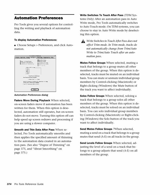
374
Automation PreferencesPro Tools gives you several options for control-ling the writing and playback of automation data.
To display Automation Preferences:
■ Choose Setups > Preferences, and click Auto-mation.
Faders Move During Playback When selected, on-screen faders move if automation has been written for them. When this option is dese-lected, automation still operates, but on-screen faders do not move. Turning this option off can help speed up screen redraws and processing if you are using a slower computer.
Smooth and Thin Data After Pass When se-lected, Pro Tools automatically smooths and then applies the specified amount of thinning to the automation data created in an automa-tion pass. (See also “Degree of Thinning” on page 375, and “About Smoothing” on page 375.)
Automation Preferences dialog
Pro Tools Reference Guide
Write Switches To Touch After Pass (TDM Sys-tems Only) After an automation pass in Auto Write mode, Pro Tools automatically switches to Auto Touch mode. On TDM systems, you can choose to stay in Auto Write mode by deselect-ing this option.
Mutes Follow Groups When selected, muting a track that belongs to a group mutes all other members of the group. When this option is de-selected, tracks must be muted on an individual basis. You can mute or unmute individual group members by Control-clicking (Macintosh) or Right-clicking (Windows) the Mute button of the track you want to affect individually.
Solos Follow Groups When selected, soloing a track that belongs to a group solos all other members of the group. When this option is de-selected, tracks must be soloed on an individual basis. You can solo individual group members by Control-clicking (Macintosh) or Right-click-ing (Windows) the Solo button of the track you want to affect individually.
Send Mutes Follow Groups ?When selected, muting a send on a track that belongs to a group mutes that send (A-E) on all tracks in the group.
Send Levels Follow Groups When selected, ad-justing the level of a send on a track that be-longs to a group adjusts that send (A-E) on all members of the group.
Write Switches to Touch After Pass does not affect Trim mode. In Trim mode, tracks do not automatically change from Trim/Auto Write to Trim/Auto Touch after an auto-mation pass.
LFEs Follow Groups When selected, adjusting the level of an LFE slider, or editing LFE automa-tion breakpoint data, on a track or send that be-longs to a group adjusts the LFE on all tracks of the group. With send-based LFEs, grouping af-fects only that send (A-E) on other tracks.
Degree of Thinning Specifies the amount of thin-ning performed on automation data when you use the Thin Automation command, or if you have selected the Smooth and Thin Data After Pass option in this dialog. (See also “About Thin-ning” on page 375.)
Touch Timeout If you are writing automation in Auto Touch mode and you stop moving a non-touch sensitive control, Pro Tools continues to write automation for the Touch Timeout value.
After the Touch Timeout period, writing of au-tomation stops and the automation data returns to its previous automation value at the rate spec-ified in the AutoMatch Time setting.
AutoMatch Time If you are writing automation in Auto Touch mode, when you release a fader or control, writing of automation stops and the automation data returns to its previous automa-tion value. The rate of return to the previous value is the AutoMatch Time. See “About Au-toMatch” on page 375.
Amount of memory to reserve for automation re-cording Allocates memory for automation. See “Setting the Automation Buffer Size” on page 376 for details.
About Smoothing
When you perform automation moves with a continuous control, Pro Tools records the move as a series of very small steps, resulting in a stair-case pattern with many breakpoints. Smoothing intelligently resolves this staircase pattern into a single, smooth ramp from one breakpoint to the next. (Smoothing does not apply to switched controls such as mutes or plug-in bypasses.) With smoothing enabled, the resulting automa-tion is often a more accurate representation of actual automation moves.
About Thinning
Thinning automatically reduces the overall number of breakpoints in the automation play-list in order to improve system performance. The amount of thinning applied is determined by the Degree of Thinning setting in the Auto-mation Preferences. When using high amounts of thinning, the resulting automation may dif-fer noticeably from the original automation moves. Thinning only applies to audio tracks, and does not affect MIDI tracks. For instruc-tions, see “Thinning Automation” on page 383.
About AutoMatch
When you write automation in Auto Touch mode, if you release a fader during playback, Pro Tools returns to the level of any automation still on the track by ramping up or down over a certain amount of time, called the AutoMatch Time. This time value is set in the Automation Preferences.
The AutoMatch feature works with continuous controls (such as Volume or Pan) by ramping their values back to previously automated levels. There are some stepped controls (for example,
Chapter 28: Automation 375
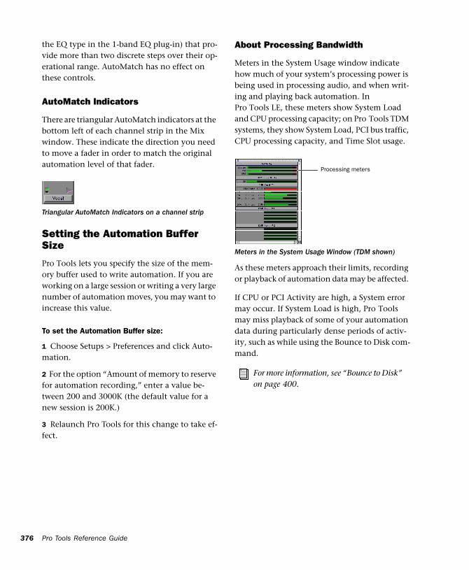
376
the EQ type in the 1-band EQ plug-in) that pro-vide more than two discrete steps over their op-erational range. AutoMatch has no effect on these controls.
AutoMatch Indicators
There are triangular AutoMatch indicators at the bottom left of each channel strip in the Mix window. These indicate the direction you need to move a fader in order to match the original automation level of that fader.
Setting the Automation Buffer Size
Pro Tools lets you specify the size of the mem-ory buffer used to write automation. If you are working on a large session or writing a very large number of automation moves, you may want to increase this value.
To set the Automation Buffer size:
1 Choose Setups > Preferences and click Auto-mation.
2 For the option “Amount of memory to reserve for automation recording,” enter a value be-tween 200 and 3000K (the default value for a new session is 200K.)
3 Relaunch Pro Tools for this change to take ef-fect.
Triangular AutoMatch Indicators on a channel strip
Pro Tools Reference Guide
About Processing Bandwidth
Meters in the System Usage window indicate how much of your system’s processing power is being used in processing audio, and when writ-ing and playing back automation. In Pro Tools LE, these meters show System Load and CPU processing capacity; on Pro Tools TDM systems, they show System Load, PCI bus traffic, CPU processing capacity, and Time Slot usage.
As these meters approach their limits, recording or playback of automation data may be affected.
If CPU or PCI Activity are high, a System error may occur. If System Load is high, Pro Tools may miss playback of some of your automation data during particularly dense periods of activ-ity, such as while using the Bounce to Disk com-mand.
Meters in the System Usage Window (TDM shown)
For more information, see “Bounce to Disk” on page 400.
Processing meters
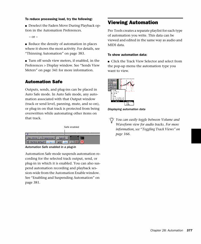
To reduce processing load, try the following:
■ Deselect the Faders Move During Playback op-tion in the Automation Preferences.
– or –
■ Reduce the density of automation in places where it shows the most activity. For details, see “Thinning Automation” on page 383.
■ Turn off sends view meters, if enabled, in the Preferences > Display window. See “Sends View Meters” on page 341 for more information.
Automation Safe
Outputs, sends, and plug-ins can be placed in Auto Safe mode. In Auto Safe mode, any auto-mation associated with that Output window (track or send level, panning, mute, and so on), or plug-in on that track is protected from being overwritten while automating other items on that track.
Automation Safe mode suspends automation re-cording for the selected track output, send, or plug-in in which it is enabled. You can also sus-pend automation recording and playback ses-sion-wide from the Automation Enable window. See “Enabling and Suspending Automation” on page 381.
Automation Safe enabled in a plug-in
Safe enabled
Viewing AutomationPro Tools creates a separate playlist for each type of automation you write. This data can be viewed and edited in the same way as audio and MIDI data.
To show automation data:
■ Click the Track View Selector and select from the pop-up menu the automation type you want to view.
Displaying automation data
You can easily toggle between Volume and Waveform view for audio tracks. For more information, see “Toggling Track Views” on page 166.
Chapter 28: Automation 377
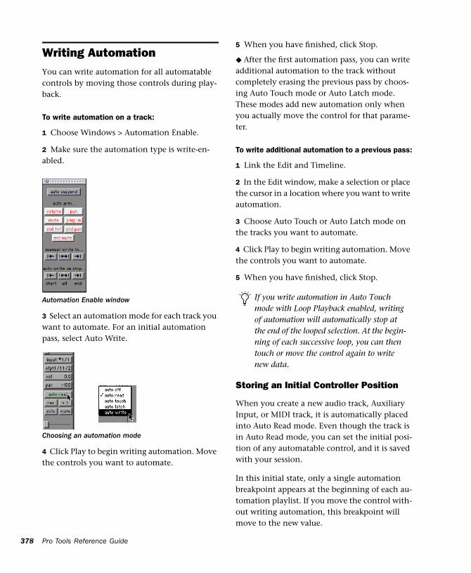
378
Writing AutomationYou can write automation for all automatable controls by moving those controls during play-back.
To write automation on a track:
1 Choose Windows > Automation Enable.
2 Make sure the automation type is write-en-abled.
3 Select an automation mode for each track you want to automate. For an initial automation pass, select Auto Write.
4 Click Play to begin writing automation. Move the controls you want to automate.
Automation Enable window
Choosing an automation mode
Pro Tools Reference Guide
5 When you have finished, click Stop.
◆ After the first automation pass, you can write additional automation to the track without completely erasing the previous pass by choos-ing Auto Touch mode or Auto Latch mode. These modes add new automation only when you actually move the control for that parame-ter.
To write additional automation to a previous pass:
1 Link the Edit and Timeline.
2 In the Edit window, make a selection or place the cursor in a location where you want to write automation.
3 Choose Auto Touch or Auto Latch mode on the tracks you want to automate.
4 Click Play to begin writing automation. Move the controls you want to automate.
5 When you have finished, click Stop.
Storing an Initial Controller Position
When you create a new audio track, Auxiliary Input, or MIDI track, it is automatically placed into Auto Read mode. Even though the track is in Auto Read mode, you can set the initial posi-tion of any automatable control, and it is saved with your session.
In this initial state, only a single automation breakpoint appears at the beginning of each au-tomation playlist. If you move the control with-out writing automation, this breakpoint will move to the new value.
If you write automation in Auto Touch mode with Loop Playback enabled, writing of automation will automatically stop at the end of the looped selection. At the begin-ning of each successive loop, you can then touch or move the control again to write new data.
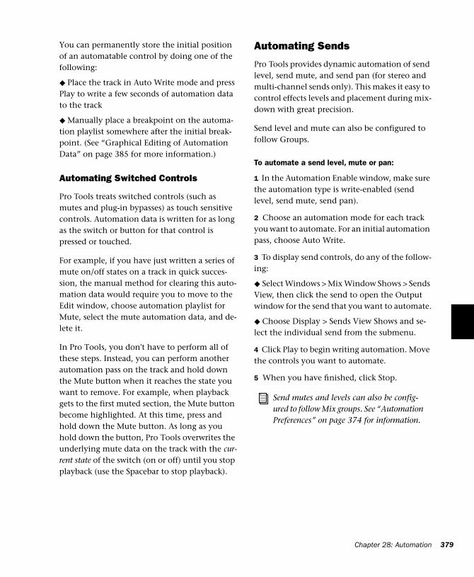
You can permanently store the initial position of an automatable control by doing one of the following:
◆ Place the track in Auto Write mode and press Play to write a few seconds of automation data to the track
◆ Manually place a breakpoint on the automa-tion playlist somewhere after the initial break-point. (See “Graphical Editing of Automation Data” on page 385 for more information.)
Automating Switched Controls
Pro Tools treats switched controls (such as mutes and plug-in bypasses) as touch sensitive controls. Automation data is written for as long as the switch or button for that control is pressed or touched.
For example, if you have just written a series of mute on/off states on a track in quick succes-sion, the manual method for clearing this auto-mation data would require you to move to the Edit window, choose automation playlist for Mute, select the mute automation data, and de-lete it.
In Pro Tools, you don't have to perform all of these steps. Instead, you can perform another automation pass on the track and hold down the Mute button when it reaches the state you want to remove. For example, when playback gets to the first muted section, the Mute button become highlighted. At this time, press and hold down the Mute button. As long as you hold down the button, Pro Tools overwrites the underlying mute data on the track with the cur-rent state of the switch (on or off) until you stop playback (use the Spacebar to stop playback).
Automating Sends
Pro Tools provides dynamic automation of send level, send mute, and send pan (for stereo and multi-channel sends only). This makes it easy to control effects levels and placement during mix-down with great precision.
Send level and mute can also be configured to follow Groups.
To automate a send level, mute or pan:
1 In the Automation Enable window, make sure the automation type is write-enabled (send level, send mute, send pan).
2 Choose an automation mode for each track you want to automate. For an initial automation pass, choose Auto Write.
3 To display send controls, do any of the follow-ing:
◆ Select Windows > Mix Window Shows > Sends View, then click the send to open the Output window for the send that you want to automate.
◆ Choose Display > Sends View Shows and se-lect the individual send from the submenu.
4 Click Play to begin writing automation. Move the controls you want to automate.
5 When you have finished, click Stop.
Send mutes and levels can also be config-ured to follow Mix groups. See “Automation Preferences” on page 374 for information.
Chapter 28: Automation 379
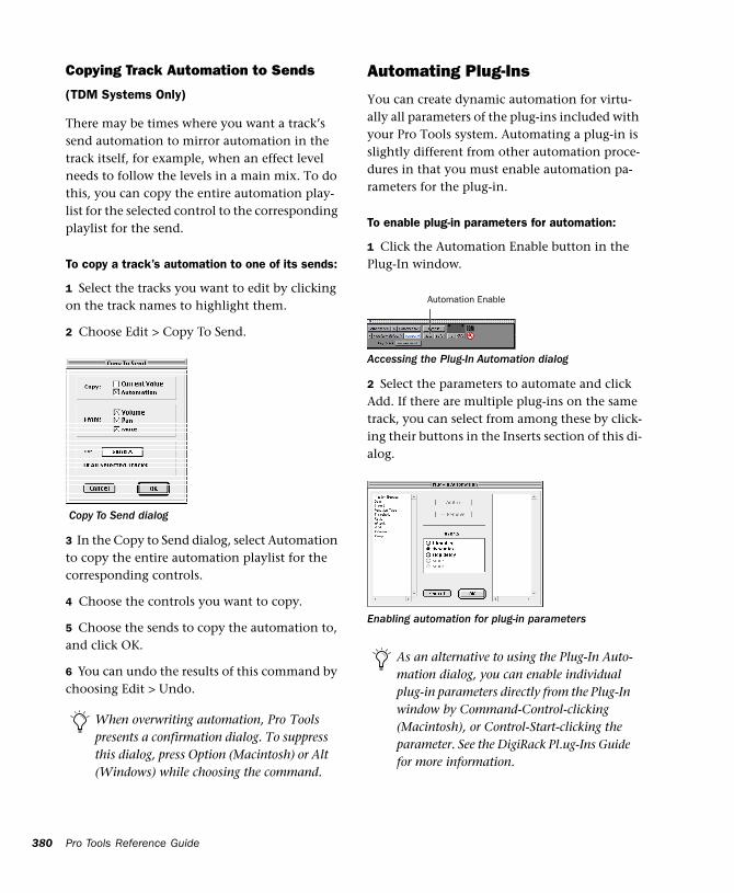
380
Copying Track Automation to Sends
(TDM Systems Only)
There may be times where you want a track’s send automation to mirror automation in the track itself, for example, when an effect level needs to follow the levels in a main mix. To do this, you can copy the entire automation play-list for the selected control to the corresponding playlist for the send.
To copy a track’s automation to one of its sends:
1 Select the tracks you want to edit by clicking on the track names to highlight them.
2 Choose Edit > Copy To Send.
3 In the Copy to Send dialog, select Automation to copy the entire automation playlist for the corresponding controls.
4 Choose the controls you want to copy.
5 Choose the sends to copy the automation to, and click OK.
6 You can undo the results of this command by choosing Edit > Undo.
Copy To Send dialog
When overwriting automation, Pro Tools presents a confirmation dialog. To suppress this dialog, press Option (Macintosh) or Alt (Windows) while choosing the command.
Pro Tools Reference Guide
Automating Plug-Ins
You can create dynamic automation for virtu-ally all parameters of the plug-ins included with your Pro Tools system. Automating a plug-in is slightly different from other automation proce-dures in that you must enable automation pa-rameters for the plug-in.
To enable plug-in parameters for automation:
1 Click the Automation Enable button in the Plug-In window.
2 Select the parameters to automate and click Add. If there are multiple plug-ins on the same track, you can select from among these by click-ing their buttons in the Inserts section of this di-alog.
Accessing the Plug-In Automation dialog
Enabling automation for plug-in parameters
As an alternative to using the Plug-In Auto-mation dialog, you can enable individual plug-in parameters directly from the Plug-In window by Command-Control-clicking (Macintosh), or Control-Start-clicking the parameter. See the DigiRack Pl.ug-Ins Guide for more information.
Automation Enable
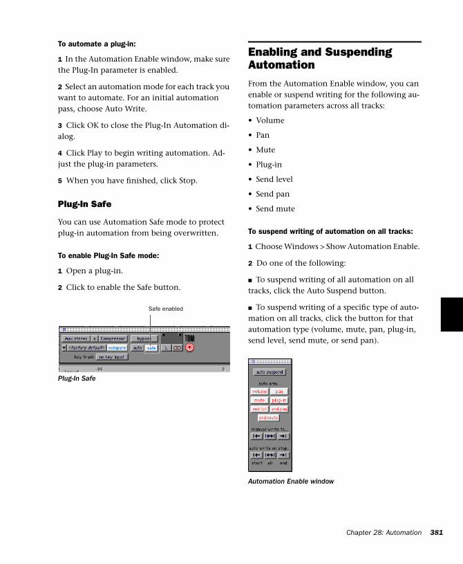
To automate a plug-in:
1 In the Automation Enable window, make sure the Plug-In parameter is enabled.
2 Select an automation mode for each track you want to automate. For an initial automation pass, choose Auto Write.
3 Click OK to close the Plug-In Automation di-alog.
4 Click Play to begin writing automation. Ad-just the plug-in parameters.
5 When you have finished, click Stop.
Plug-In Safe
You can use Automation Safe mode to protect plug-in automation from being overwritten.
To enable Plug-In Safe mode:
1 Open a plug-in.
2 Click to enable the Safe button.
Plug-In Safe
Safe enabled
Enabling and Suspending AutomationFrom the Automation Enable window, you can enable or suspend writing for the following au-tomation parameters across all tracks:
• Volume
• Pan
• Mute
• Plug-in
• Send level
• Send pan
• Send mute
To suspend writing of automation on all tracks:
1 Choose Windows > Show Automation Enable.
2 Do one of the following:
■ To suspend writing of all automation on all tracks, click the Auto Suspend button.
■ To suspend writing of a specific type of auto-mation on all tracks, click the button for that automation type (volume, mute, pan, plug-in, send level, send mute, or send pan).
Automation Enable window
Chapter 28: Automation 381
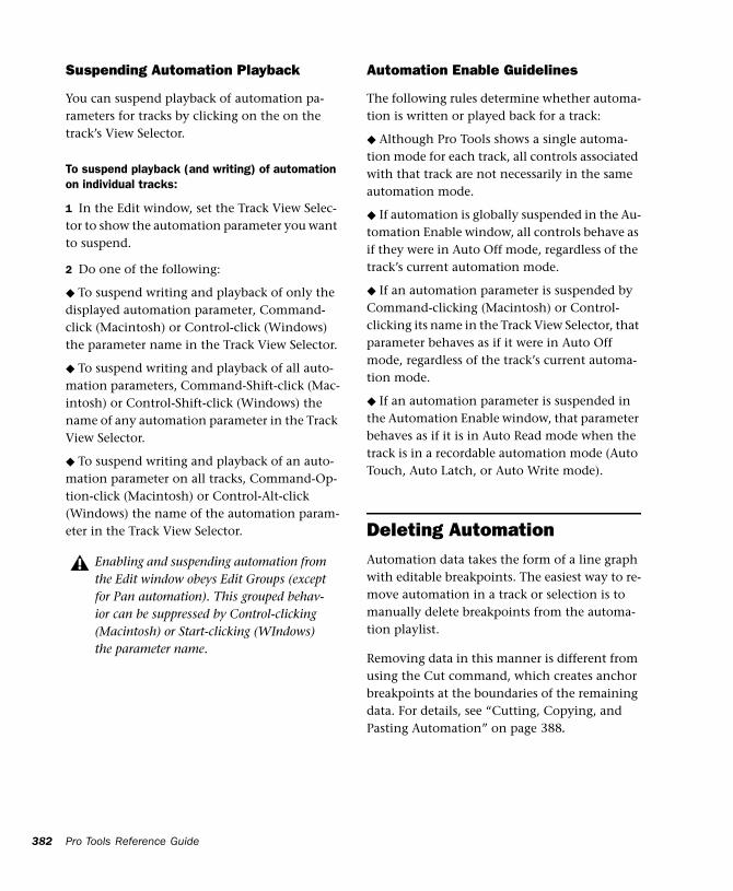
382
Suspending Automation Playback
You can suspend playback of automation pa-rameters for tracks by clicking on the on the track’s View Selector.
To suspend playback (and writing) of automation on individual tracks:
1 In the Edit window, set the Track View Selec-tor to show the automation parameter you want to suspend.
2 Do one of the following:
◆ To suspend writing and playback of only the displayed automation parameter, Command-click (Macintosh) or Control-click (Windows) the parameter name in the Track View Selector.
◆ To suspend writing and playback of all auto-mation parameters, Command-Shift-click (Mac-intosh) or Control-Shift-click (Windows) the name of any automation parameter in the Track View Selector.
◆ To suspend writing and playback of an auto-mation parameter on all tracks, Command-Op-tion-click (Macintosh) or Control-Alt-click (Windows) the name of the automation param-eter in the Track View Selector.
Enabling and suspending automation from the Edit window obeys Edit Groups (except for Pan automation). This grouped behav-ior can be suppressed by Control-clicking (Macintosh) or Start-clicking (WIndows) the parameter name.
Pro Tools Reference Guide
Automation Enable Guidelines
The following rules determine whether automa-tion is written or played back for a track:
◆ Although Pro Tools shows a single automa-tion mode for each track, all controls associated with that track are not necessarily in the same automation mode.
◆ If automation is globally suspended in the Au-tomation Enable window, all controls behave as if they were in Auto Off mode, regardless of the track’s current automation mode.
◆ If an automation parameter is suspended by Command-clicking (Macintosh) or Control-clicking its name in the Track View Selector, that parameter behaves as if it were in Auto Off mode, regardless of the track’s current automa-tion mode.
◆ If an automation parameter is suspended in the Automation Enable window, that parameter behaves as if it is in Auto Read mode when the track is in a recordable automation mode (Auto Touch, Auto Latch, or Auto Write mode).
Deleting AutomationAutomation data takes the form of a line graph with editable breakpoints. The easiest way to re-move automation in a track or selection is to manually delete breakpoints from the automa-tion playlist.
Removing data in this manner is different from using the Cut command, which creates anchor breakpoints at the boundaries of the remaining data. For details, see “Cutting, Copying, and Pasting Automation” on page 388.
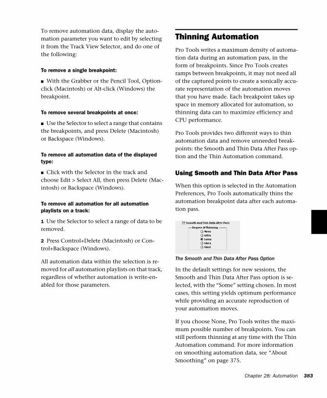
To remove automation data, display the auto-mation parameter you want to edit by selecting it from the Track View Selector, and do one of the following:
To remove a single breakpoint:
■ With the Grabber or the Pencil Tool, Option-click (Macintosh) or Alt-click (Windows) the breakpoint.
To remove several breakpoints at once:
■ Use the Selector to select a range that contains the breakpoints, and press Delete (Macintosh) or Backspace (Windows).
To remove all automation data of the displayed type:
■ Click with the Selector in the track and choose Edit > Select All, then press Delete (Mac-intosh) or Backspace (Windows).
To remove all automation for all automation playlists on a track:
1 Use the Selector to select a range of data to be removed.
2 Press Control+Delete (Macintosh) or Con-trol+Backspace (Windows).
All automation data within the selection is re-moved for all automation playlists on that track, regardless of whether automation is write-en-abled for those parameters.
Thinning AutomationPro Tools writes a maximum density of automa-tion data during an automation pass, in the form of breakpoints. Since Pro Tools creates ramps between breakpoints, it may not need all of the captured points to create a sonically accu-rate representation of the automation moves that you have made. Each breakpoint takes up space in memory allocated for automation, so thinning data can to maximize efficiency and CPU performance.
Pro Tools provides two different ways to thin automation data and remove unneeded break-points: the Smooth and Thin Data After Pass op-tion and the Thin Automation command.
Using Smooth and Thin Data After Pass
When this option is selected in the Automation Preferences, Pro Tools automatically thins the automation breakpoint data after each automa-tion pass.
In the default settings for new sessions, the Smooth and Thin Data After Pass option is se-lected, with the “Some” setting chosen. In most cases, this setting yields optimum performance while providing an accurate reproduction of your automation moves.
If you choose None, Pro Tools writes the maxi-mum possible number of breakpoints. You can still perform thinning at any time with the Thin Automation command. For more information on smoothing automation data, see “About Smoothing” on page 375.
The Smooth and Thin Data After Pass Option
Chapter 28: Automation 383
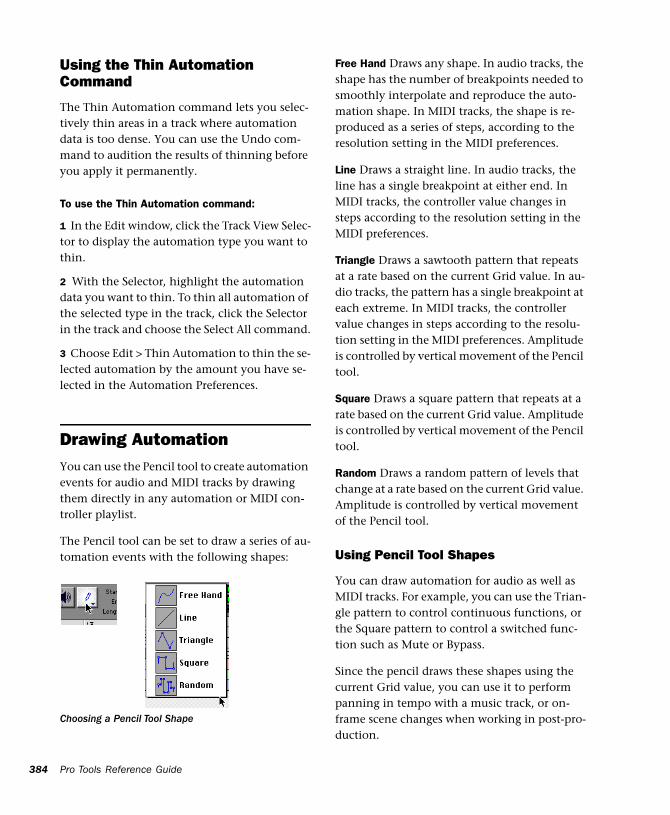
384
Using the Thin Automation Command
The Thin Automation command lets you selec-tively thin areas in a track where automation data is too dense. You can use the Undo com-mand to audition the results of thinning before you apply it permanently.
To use the Thin Automation command:
1 In the Edit window, click the Track View Selec-tor to display the automation type you want to thin.
2 With the Selector, highlight the automation data you want to thin. To thin all automation of the selected type in the track, click the Selector in the track and choose the Select All command.
3 Choose Edit > Thin Automation to thin the se-lected automation by the amount you have se-lected in the Automation Preferences.
Drawing AutomationYou can use the Pencil tool to create automation events for audio and MIDI tracks by drawing them directly in any automation or MIDI con-troller playlist.
The Pencil tool can be set to draw a series of au-tomation events with the following shapes:
Choosing a Pencil Tool Shape
Pro Tools Reference Guide
Free Hand Draws any shape. In audio tracks, the shape has the number of breakpoints needed to smoothly interpolate and reproduce the auto-mation shape. In MIDI tracks, the shape is re-produced as a series of steps, according to the resolution setting in the MIDI preferences.
Line Draws a straight line. In audio tracks, the line has a single breakpoint at either end. In MIDI tracks, the controller value changes in steps according to the resolution setting in the MIDI preferences.
Triangle Draws a sawtooth pattern that repeats at a rate based on the current Grid value. In au-dio tracks, the pattern has a single breakpoint at each extreme. In MIDI tracks, the controller value changes in steps according to the resolu-tion setting in the MIDI preferences. Amplitude is controlled by vertical movement of the Pencil tool.
Square Draws a square pattern that repeats at a rate based on the current Grid value. Amplitude is controlled by vertical movement of the Pencil tool.
Random Draws a random pattern of levels that change at a rate based on the current Grid value. Amplitude is controlled by vertical movement of the Pencil tool.
Using Pencil Tool Shapes
You can draw automation for audio as well as MIDI tracks. For example, you can use the Trian-gle pattern to control continuous functions, or the Square pattern to control a switched func-tion such as Mute or Bypass.
Since the pencil draws these shapes using the current Grid value, you can use it to perform panning in tempo with a music track, or on-frame scene changes when working in post-pro-duction.
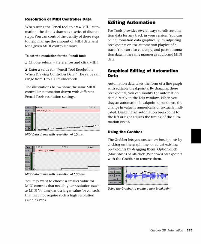
Resolution of MIDI Controller Data
When using the Pencil tool to draw MIDI auto-mation, the data is drawn as a series of discrete steps. You can control the density of these steps to help manage the amount of MIDI data sent for a given MIDI controller move.
To set the resolution for the Pencil tool:
1 Choose Setups > Preferences and click MIDI.
2 Enter a value for “Pencil Tool Resolution When Drawing Controller Data.” The value can range from 1 to 100 milliseconds.
The illustrations below show the same MIDI controller automation drawn with different Pencil Tools resolution settings.
You may want to choose a smaller value for MIDI controls that need higher resolution (such as MIDI Volume), and a larger value for controls that may not require such a high resolution (such as Pan).
MIDI Data drawn with resolution of 10 ms
MIDI Data drawn with resolution of 100 ms
Editing AutomationPro Tools provides several ways to edit automa-tion data for any track in your session. You can edit automation data graphically, by adjusting breakpoints on the automation playlist of a track. You can also cut, copy, and paste automa-tion data in the same manner as audio and MIDI data.
Graphical Editing of Automation Data
Automation data takes the form of a line graph with editable breakpoints. By dragging these breakpoints, you can modify the automation data directly in the Edit window. When you drag an automation breakpoint up or down, the change in value is numerically or textually indi-cated. Dragging an automation breakpoint to the left or right adjusts the timing of the auto-mation event.
Using the Grabber
The Grabber lets you create new breakpoints by clicking on the graph line, or adjust existing breakpoints by dragging them. Option-click (Macintosh) or Alt-click (Windows) breakpoints with the Grabber to remove them.
Using the Grabber to create a new breakpoint
Chapter 28: Automation 385
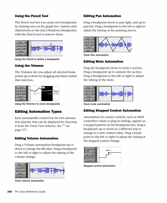
386
Using the Pencil Tool
The Pencil tool lets you create new breakpoints by clicking once on the graph line. Option-click (Macintosh) or Alt-click (Windows) breakpoints with the Pencil tool to remove them.
Using the Trimmer
The Trimmer lets you adjust all selected break-points up or down by dragging anywhere within that selection.
Editing Automation Types
Each automatable control has its own automa-tion playlist, that can be displayed by choosing it from the Track View Selector. See “” on page 377.
Editing Volume Automation
Drag a Volume automation breakpoint up or down to change the dB value. Drag a breakpoint to the left or right to adjust the timing of the volume change.
Using the Pencil to delete a breakpoint
Using the Trimmer to move breakpoints
Track volume automation
Pro Tools Reference Guide
Editing Pan Automation
Drag a breakpoint down to pan right, and up to pan left. Drag a breakpoint to the left or right to adjust the timing of the panning moves.
Editing Mute Automation
Drag the breakpoint down to mute a section. Drag a breakpoint up to unmute the section. Drag a breakpoint to the left or right to adjust the timing of the mute.
Editing Stepped Control Automation
Automation for certain controls, such as MIDI controllers values or plug-in settings, appears as a stepped pattern on the breakpoint line. Drag a breakpoint up or down to a different step to change to a new control value. Drag a break-point to the left or right to adjust the timing of the stepped control change.
Track Pan automation
Track mute automation
Stepped control automation
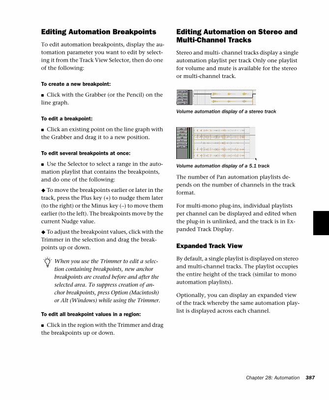
Editing Automation Breakpoints
To edit automation breakpoints, display the au-tomation parameter you want to edit by select-ing it from the Track View Selector, then do one of the following:
To create a new breakpoint:
■ Click with the Grabber (or the Pencil) on the line graph.
To edit a breakpoint:
■ Click an existing point on the line graph with the Grabber and drag it to a new position.
To edit several breakpoints at once:
■ Use the Selector to select a range in the auto-mation playlist that contains the breakpoints, and do one of the following:
◆ To move the breakpoints earlier or later in the track, press the Plus key (+) to nudge them later (to the right) or the Minus key (–) to move them earlier (to the left). The breakpoints move by the current Nudge value.
◆ To adjust the breakpoint values, click with the Trimmer in the selection and drag the break-points up or down.
To edit all breakpoint values in a region:
■ Click in the region with the Trimmer and drag the breakpoints up or down.
When you use the Trimmer to edit a selec-tion containing breakpoints, new anchor breakpoints are created before and after the selected area. To suppress creation of an-chor breakpoints, press Option (Macintosh) or Alt (Windows) while using the Trimmer.
Editing Automation on Stereo and Multi-Channel Tracks
Stereo and multi- channel tracks display a single automation playlist per track Only one playlist for volume and mute is available for the stereo or multi-channel track.
The number of Pan automation playlists de-pends on the number of channels in the track format.
For multi-mono plug-ins, individual playlists per channel can be displayed and edited when the plug-in is unlinked, and the track is in Ex-panded Track Display.
Expanded Track View
By default, a single playlist is displayed on stereo and multi-channel tracks. The playlist occupies the entire height of the track (similar to mono automation playlists).
Optionally, you can display an expanded view of the track whereby the same automation play-list is displayed across each channel.
Volume automation display of a stereo track
Volume automation display of a 5.1 track
Chapter 28: Automation 387
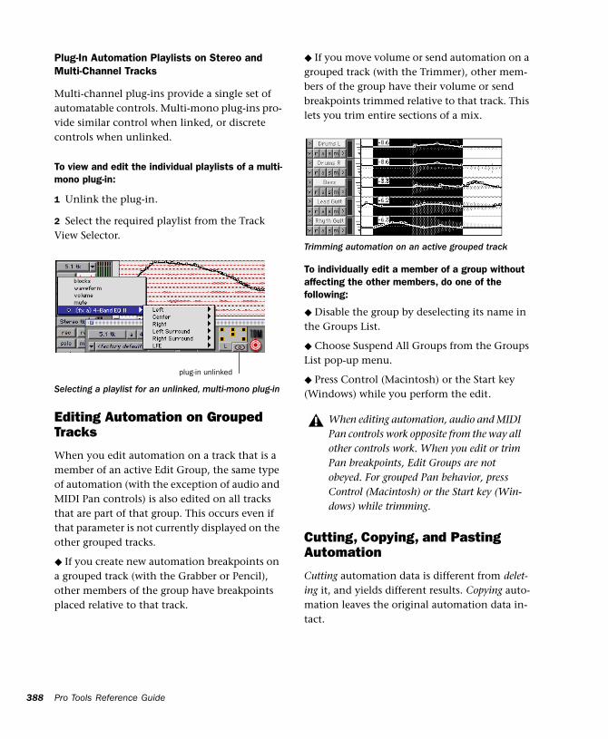
388
Plug-In Automation Playlists on Stereo and Multi-Channel Tracks
Multi-channel plug-ins provide a single set of automatable controls. Multi-mono plug-ins pro-vide similar control when linked, or discrete controls when unlinked.
To view and edit the individual playlists of a multi-mono plug-in:
1 Unlink the plug-in.
2 Select the required playlist from the Track View Selector.
Editing Automation on Grouped Tracks
When you edit automation on a track that is a member of an active Edit Group, the same type of automation (with the exception of audio and MIDI Pan controls) is also edited on all tracks that are part of that group. This occurs even if that parameter is not currently displayed on the other grouped tracks.
◆ If you create new automation breakpoints on a grouped track (with the Grabber or Pencil), other members of the group have breakpoints placed relative to that track.
Selecting a playlist for an unlinked, multi-mono plug-in
plug-in unlinked
Pro Tools Reference Guide
◆ If you move volume or send automation on a grouped track (with the Trimmer), other mem-bers of the group have their volume or send breakpoints trimmed relative to that track. This lets you trim entire sections of a mix.
To individually edit a member of a group without affecting the other members, do one of the following:
◆ Disable the group by deselecting its name in the Groups List.
◆ Choose Suspend All Groups from the Groups List pop-up menu.
◆ Press Control (Macintosh) or the Start key (Windows) while you perform the edit.
Cutting, Copying, and Pasting Automation
Cutting automation data is different from delet-ing it, and yields different results. Copying auto-mation leaves the original automation data in-tact.
Trimming automation on an active grouped track
When editing automation, audio and MIDI Pan controls work opposite from the way all other controls work. When you edit or trim Pan breakpoints, Edit Groups are not obeyed. For grouped Pan behavior, press Control (Macintosh) or the Start key (Win-dows) while trimming.
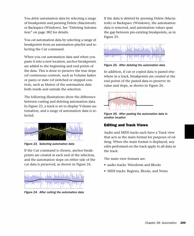
You delete automation data by selecting a range of breakpoints and pressing Delete (Macintosh) or Backspace (Windows). See “Deleting Automa-tion” on page 382 for details.
You cut automation data by selecting a range of breakpoints from an automation playlist and se-lecting the Cut command.
When you cut automation data and when you paste it into a new location, anchor breakpoints are added to the beginning and end points of the data. This is done to preserve the true slope (of continuous controls, such as Volume faders or pans) or state (of switched or stepped con-trols, such as Mutes) of the automation data both inside and outside the selection.
The following illustrations show the difference between cutting and deleting automation data. In Figure 23, a track is set to display Volume au-tomation, and a range of automation data is se-lected.
If the Cut command is chosen, anchor break-points are created at each end of the selection, and the automation slope on either side of the cut data is preserved, as shown in Figure 24.
Figure 23. Selecting automation data
Figure 24. After cutting the automation data
If the data is deleted by pressing Delete (Macin-tosh) or Backspace (Windows), the automation data is removed, and automation values span the gap between pre-existing breakpoints, as in Figure 25.
In addition, if cut or copied data is pasted else-where in a track, breakpoints are created at the end points of the pasted data to preserve its value and slope, as shown in Figure 26.
Editing and Track Views
Audio and MIDI tracks each have a Track view that acts as the main format for purposes of ed-iting. When the main format is displayed, any edits performed on the track apply to all data in the track.
The main view formats are:
• audio tracks: Waveform and Blocks
• MIDI tracks: Regions, Blocks, and Notes
Figure 25. After deleting the automation data
Figure 26. After pasting the automation data in another location
Chapter 28: Automation 389
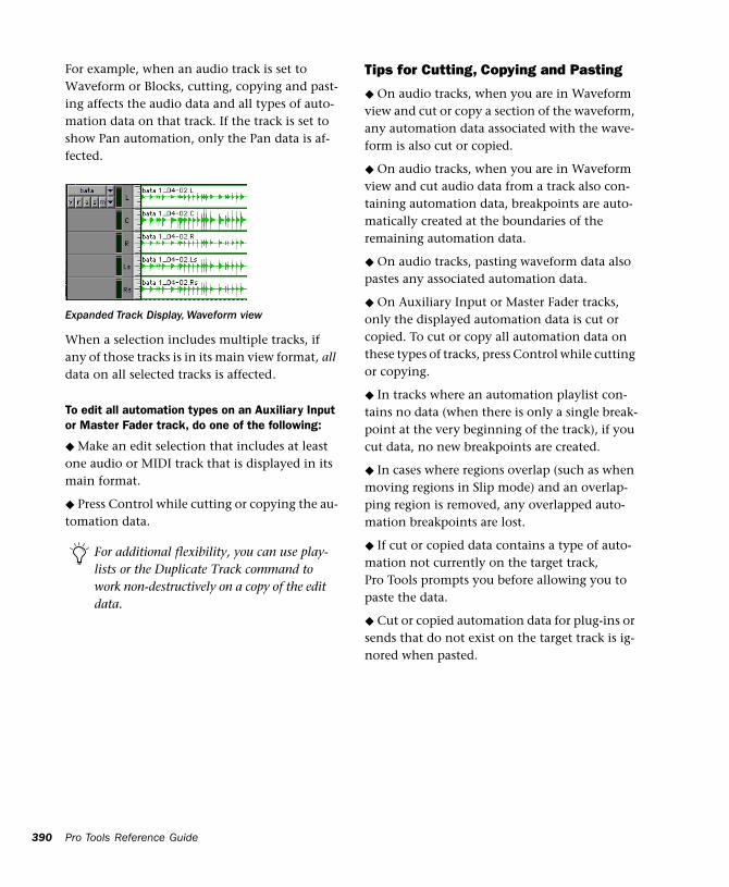
390
For example, when an audio track is set to Waveform or Blocks, cutting, copying and past-ing affects the audio data and all types of auto-mation data on that track. If the track is set to show Pan automation, only the Pan data is af-fected.
When a selection includes multiple tracks, if any of those tracks is in its main view format, all data on all selected tracks is affected.
To edit all automation types on an Auxiliary Input or Master Fader track, do one of the following:
◆ Make an edit selection that includes at least one audio or MIDI track that is displayed in its main format.
◆ Press Control while cutting or copying the au-tomation data.
Expanded Track Display, Waveform view
For additional flexibility, you can use play-lists or the Duplicate Track command to work non-destructively on a copy of the edit data.
Pro Tools Reference Guide
Tips for Cutting, Copying and Pasting
◆ On audio tracks, when you are in Waveform view and cut or copy a section of the waveform, any automation data associated with the wave-form is also cut or copied.
◆ On audio tracks, when you are in Waveform view and cut audio data from a track also con-taining automation data, breakpoints are auto-matically created at the boundaries of the remaining automation data.
◆ On audio tracks, pasting waveform data also pastes any associated automation data.
◆ On Auxiliary Input or Master Fader tracks, only the displayed automation data is cut or copied. To cut or copy all automation data on these types of tracks, press Control while cutting or copying.
◆ In tracks where an automation playlist con-tains no data (when there is only a single break-point at the very beginning of the track), if you cut data, no new breakpoints are created.
◆ In cases where regions overlap (such as when moving regions in Slip mode) and an overlap-ping region is removed, any overlapped auto-mation breakpoints are lost.
◆ If cut or copied data contains a type of auto-mation not currently on the target track, Pro Tools prompts you before allowing you to paste the data.
◆ Cut or copied automation data for plug-ins or sends that do not exist on the target track is ig-nored when pasted.
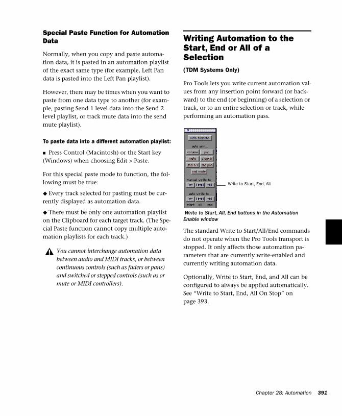
Special Paste Function for Automation Data
Normally, when you copy and paste automa-tion data, it is pasted in an automation playlist of the exact same type (for example, Left Pan data is pasted into the Left Pan playlist).
However, there may be times when you want to paste from one data type to another (for exam-ple, pasting Send 1 level data into the Send 2 level playlist, or track mute data into the send mute playlist).
To paste data into a different automation playlist:
■ Press Control (Macintosh) or the Start key (Windows) when choosing Edit > Paste.
For this special paste mode to function, the fol-lowing must be true:
◆ Every track selected for pasting must be cur-rently displayed as automation data.
◆ There must be only one automation playlist on the Clipboard for each target track. (The Spe-cial Paste function cannot copy multiple auto-mation playlists for each track.)
You cannot interchange automation data between audio and MIDI tracks, or between continuous controls (such as faders or pans) and switched or stepped controls (such as or mute or MIDI controllers).
Writing Automation to the Start, End or All of a Selection(TDM Systems Only)
Pro Tools lets you write current automation val-ues from any insertion point forward (or back-ward) to the end (or beginning) of a selection or track, or to an entire selection or track, while performing an automation pass.
The standard Write to Start/All/End commands do not operate when the Pro Tools transport is stopped. It only affects those automation pa-rameters that are currently write-enabled and currently writing automation data.
Optionally, Write to Start, End, and All can be configured to always be applied automatically. See “Write to Start, End, All On Stop” on page 393.
Write to Start, All, End buttons in the Automation Enable window
Write to Start, End, All
Chapter 28: Automation 391
392
Requirements for Write to Start, End, and All
For an automation parameter to write automa-tion data, the associated track must be in one of the following automation modes and meet the following conditions:
Latch mode The automation parameter must be changed (touched) during the automation pass.
Touch mode The automation parameter must be changed (touched).
Write mode All automation parameters on that track must be in Auto Write mode.
This command can be undone by choosing Edit > Undo.
To write current automation values to the start, end, or all of a track or selection:
1 In the Automation Enable window, make sure that the automation type is write-enabled.
2 Click in a track at an insertion point.
– or –
Drag with the Selector to select a portion of the track.
3 Click Play to begin playback.
4 When you reach a point in the track that con-tains the automation data, click Write to Start, Write to All, or Write to End in the Automation Enable window.
The current values of all write-enabled automa-tion at that point are written to the correspond-ing area of the track/selection.
Pro Tools Reference Guide
Trim Mode
Using Trim mode, it is also possible to write trim delta values for track volume and send levels to the beginning, end or all of a track.
To write current trim delta values to the start, end, or all of a track or selection:
1 In the Automation Enable window, make sure that the automation type (track volume or send level) is write-enabled.
2 Click the Automation Mode Selector on the track. Select Trim from the pop-up menu to en-able Trim mode. The track volume and send level faders turn yellow.
3 Click in a track at an insertion point.
– or –
Drag with the Selector to select a portion of the track.
4 Click Play to begin playback.
5 When you reach a point in the track/selection that contains the trim setting (delta value) you want to apply, click the Write to Start, Write to All, or Write to End button in the Automation Enable window.
The relative changes to the track volume and send levels at that point are written to the corre-sponding area of the track/selection.
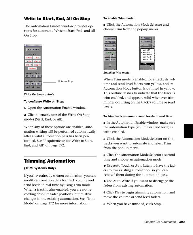
Write to Start, End, All On Stop
The Automation Enable window provides op-tions for automatic Write to Start, End, and All On Stop.
To configure Write on Stop:
1 Open the Automation Enable window.
2 Click to enable one of the Write On Stop modes (Start, End, or All).
When any of these options are enabled, auto-mation writing will be performed automatically after a valid automation pass has been per-formed. See “Requirements for Write to Start, End, and All” on page 392.
Trimming Automation(TDM Systems Only)
If you have already written automation, you can modify automation data for track volume and send levels in real time by using Trim mode. When a track is trim-enabled, you are not re-cording absolute fader positions, but relative changes in the existing automation. See “Trim Mode” on page 372 for more information.
Write On Stop controls
Write on Stop
To enable Trim mode:
■ Click the Automation Mode Selector and choose Trim from the pop-up menu.
When Trim mode is enabled for a track, its vol-ume and send level faders turn yellow, and its Automation Mode button is outlined in yellow. This outline flashes to indicate that the track is trim-enabled, and appears solid whenever trim-ming is occurring on the track’s volume or send levels.
To trim track volume or send levels in real time:
1 In the Automation Enable window, make sure the automation type (volume or send level) is write-enabled.
2 Click the Automation Mode Selector on the tracks you want to automate and select Trim from the pop-up menu.
3 Click the Automation Mode Selector a second time and choose an automation mode:
◆ Use Auto Touch or Auto Latch to have the fad-ers follow existing automation, so you can “chase” them during the automation pass.
◆ Use Auto Write if you want to disengage the faders from existing automation.
4 Click Play to begin trimming automation, and move the volume or send level faders.
5 When you have finished, click Stop.
Enabling Trim mode
Chapter 28: Automation 393
394
Creating Snapshot Automation(TDM Systems Only)
Pro Tools lets you write automation data values for multiple parameters in a single step. You can write snapshot automation in two ways:
To a selection Automation data is written to the Timeline selection (as well as the Edit selection if linked). Anchor breakpoints are placed just be-fore and after the selection so that data outside the selection is not affected.
To a cursor location Automation data is written at the insertion point. After the insertion point, the automation ramps to the next breakpoint value, or if no breakpoints exist, remains at the newly written value for the remainder of the ses-sion.
For more information on copying automation data within a session, see “Writing Automation to the Start, End or All of a Selection” on page 391.
To write snapshot automation:
1 In the Edit window, click the Track View but-ton to show the automation you want to edit.
2 In the Automation Enable window, make sure that the automation parameters you want to edit are write-enabled. Disable any parameters you want to preserve.
• Select an area in the track’s playlist (or within multiple tracks) where you want to apply the automation.
– or –
• Place the cursor at an Edit insertion point.
Pro Tools Reference Guide
3 Adjust the controls for the parameters you want to automate.
4 Choose Edit > Write Automation and do one of the following:
◆ To write the current value to only the cur-rently displayed automation parameter, choose To Current Parameter.
◆ To write the current settings for all automa-tion parameters enabled in the Automation En-able window, choose To All Enabled Parameters.
Adding Snapshot Automation to Empty Automation Playlists
When you use the Write Automation command on an automation playlist with no previously written automation data, the selected value is written to the entire playlist and not just the se-lected area.
This is because a playlist with no automation data contains only a single automation break-point that corresponds to the current position of the control. The position of the breakpoint is updated whenever the parameter value is changed.
If you do not want the Write Automation com-mand to write the selected automation value to the entire playlist, you can:
◆ Anchor the automation data by placing the cursor at the end of the session (or any other endpoint) and choosing Write Automation To Current Parameter.
– or –
◆ Click with the Grabber on each side of the se-lection.
This lets the Write Automation command write only to the selected area.

Writing Snapshot Automation over Existing Automation Data
When you move the playback cursor, the auto-mated controls in Pro Tools update on the screen to reflect the automation data that is al-ready on the track. To keep the settings you have made for a snapshot, you can suspend the desired automation parameters to prevent the controls from updating.
To write snapshot automation over existing data:
1 In the Automation Enable window, make sure that the automation parameters you want to edit are write-enabled. Deselect any parameters you want to preserve.
2 Adjust the controls for the parameters you want to automate.
3 Suspend the automation parameters you want to automate by doing any of the following:
• To suspend an automation parameter on a single track, Command-click (Macintosh) or Control-click (Windows) he name of the auto-mation type in the track’s Track View Selector.
• To suspend an automation parameter on all tracks, Command-Shift-click (Macintosh) or Control-Alt-click (Windows) the name of the automation type in the Track View Selector for any track.
• To suspend all automation on a track, Com-mand-Shift-click (Macintosh) or Control-Shift-click (Windows) the name of the auto-mation type in the Track View Selector.
4 With the Selector, select the track range you want to apply the automation.
5 Enable the automation parameters previously suspended.
6 Choose Edit > Write Automation and select one of the following from the submenu:
• To write the current value to only the automa-tion parameter currently displayed in the Edit window, choose To Current Parameter.
• To write the current settings for all automa-tion parameters enabled in the Automation Enable window, choose To All Enabled Param-eters.
Capturing Automation and Applying it Elsewhere
The Write Automation command can also be used to capture automation states at specific lo-cations in a session and apply them to other lo-cations. This differs from simply copying and pasting automation data in that you can set any selection length for the application of the cap-tured automation data.
To capture and apply automation:
1 In the Automation Enable window, make sure that the automation parameters you want to edit are write-enabled. Disable any parameters you want to preserve.
2 Click with the Selector in the track with the automation you want to capture. All automated controls update to reflect the automation at that location. (If you make a selection, the controls update to reflect the automation at the begin-ning of the selection.)
3 Suspend the automation parameters you want to automate:
• For an automation parameter on a single track, Command-click (Macintosh) or Con-trol-click (Windows) the name of the automa-tion type in that track’s Track View Selector.
Chapter 28: Automation 395
396
• For an automation parameter on all tracks, Command-Shift-click (Macintosh) or Con-trol-Alt-click (Windows) the name of the au-tomation type in the Track View Selector for any track.
• To suspend all automation on a track, Com-mand-Shift-click (Macintosh) or Control-Shift-click (Windows) the name of the auto-mation type in that track's Track View Selec-tor.
4 With the Selector tool, select the location where you want to apply the automation.
5 Enable the automation parameters previously suspended.
6 Choose Edit > Write Automation and select one of the following from the submenu:
• To write the current value to only the automa-tion parameter currently displayed in the Edit window, choose To Current Parameter.
• To write the current settings for all automa-tion parameters enabled in the Automation Enable window, choose To All Enabled Param-eters.
Snapshot Automation and Trimming of Automation Data
Pro Tools lets you use trim values as snapshots and apply the relative changes (delta values) to the selected automation by using the Trim Au-tomation command. This works in much the same way as the Write Automation, except that it writes delta values instead of absolute values to automation data.
You can use trim values in writing snapshot au-tomation to any automatable parameter.
Pro Tools Reference Guide
To create a snapshot of relative changes in automation data:
1 In the Automation Enable window, make sure that the automation parameters you want to edit are write-enabled. Disable any parameters you want to preserve.
2 Select the area of the track you want to edit. All automated controls update to reflect the au-tomation at the beginning of the selection.
3 Move the controls for the parameter up or down by the amount you want to change the data.
4 Choose Edit > Trim Automation and do one of the following:
◆ To write the current delta value to only the currently displayed automation parameter, choose To Current Parameter.
◆ To write the current delta value for all auto-mation parameters enabled in the Automation Enable window, choose To All Enabled Parame-ters.
Chapter 29: Mixdown
Pro Tools lets you record and bounce tracks to disk. The Bounce to Disk command lets you write a final mix to disk, create a new loop, print effects, or bounce any submix. You can also sub-mix, route, and record busses and inputs to new tracks.
Bounce to Disk This command writes the cur-rent session (if no selection), Edit, or Timeline selection as new audio files to disk. Any avail-able output or bus path can be selected as the bounce source. Use Bounce to Disk to write or master any output or bus path directly to disk. Sample rate, bit depth, and other conversion processes can be applied during or after the bounce. The Bounce to Disk command lets you bounce all available voices to disk without hold-ing any in reserve. Though you can hear the bounce being created in real time, you cannot adjust mixer or other controls during a Bounce to Disk.
Recording to Tracks The process of submixing and recording to new audio tracks, as you would any input signals. This method requires avail-able tracks, voices, and bus paths to accommo-date the submix and the new tracks.
Selecting Audio for Loops, Submixes, and Effects
Both Bounce to Disk and recording to tracks op-erate on the current Timeline or Edit selection, if any. This makes it easy to turn multitrack selec-tions into mono, stereo, or multi-channel loops. Submixes, stems, and and other specialized types of mixes can also be printed to disk using either method, or recorded out to a DAT, MDM, or other recording, transfer, or archiving me-dium.
Printing effects to disk is the technique of per-manently adding real-time effects, such as EQ or reverb, to an audio track by bussing and record-ing it to new tracks with the effects added. The original audio is preserved, so you can return to the source track at any time. This can be useful when you have a limited number of tracks or ef-fects devices.
Use Bounce to Disk if you need to convert the bounce files, or if you do not want or need to in-teract with mixer controls during the bounce.
Record to new tracks if you want to adjust pa-rameters while the files are being written.
AudioSuite plug-ins provide another option for printing a plug-in effect to disk. See the DigiRack Plug-Ins Guide for details.
Chapter 29: Mixdown 397
398
Dither and Bounce to Disk
Dithering can significantly improve audio qual-ity. Generally, dithering is necessary when re-ducing the bit depth for digital audio.
If you use Bounce to Disk, it is important to un-derstand that the Bounce to Disk process does not apply dither.
To dither a bounce file, you should insert the in-cluded Digidesign Dither plug-in, or another dithering plug-in, on a Master Fader assigned to the bounce source path. Master Faders are often preferable to Auxiliary Inputs because Master Fader inserts are post-fader (better for dither-ing).
If you do not use a dithering plug-in on your bounce source path, and you choose to convert to a lower resolution during or after a Bounce to Disk, the resultant file will be converted by trun-cation.
When to Use the Dither Plug-In
You should use the Dither plug-in when master-ing to a 16-bit file with the Bounce To Disk com-mand, or when mastering to an external device that records at 16-bit.
This is even necessary when using 16-bit ses-sions. Even though 16-bit sessions use 16-bit files, they are still being processed internally at a higher bit rate:
• 24-bit for Pro Tool TDM systems
• 32-bit floating for Pro Tools LE systems
For this reason, whether you are using a 16-bit session or a 24-bit session, it is recommended that you use the Dither plug-in when mastering to 16-bits.
When mastering to 24-bits, it is not necessary to use the Dither plug-in.
Pro Tools Reference Guide
Using Dither on an Output Mix
Pro Tools includes a real-time Dither plug-in that improves 16-, 18-, or 20-bit performance and reduces quantization noise when mixing or fading low-level signals.
The Dither plug-in has no user-selectable pa-rameters other than Bit Resolution and Noise Shaping controls.
To use the Dither Plug-In on a submix:
1 Choose File > New Track and choose Master Fader (stereo) from the pop-up menu.
2 Set the output of the Master Fader to the out-put or bus path you want to bounce.
3 Assign the outputs of all audio tracks in the session to the same path you chose in step 2. The Master Fader now controls the output levels of all tracks routed to it.
4 On the Master Fader, click an Insert button and choose the Digidesign Dither plug-in.
5 In the Dither plug-in window, choose an out-put Bit Resolution and Noise Shaping setting.
When you Bounce to Disk you can convert the file to the appropriate resolution. Before being converted by the Bounce to Disk command, the signal will have been dithered to the resolution and noise shaping settings in the Dither plug-in.
For more information about dither, see “Dither” on page 352.
For more information about the Dither plug-in, refer to the DigiRack Plug-Ins Guide.
Recording to TracksYou can create a submix in your Pro Tools ses-sion and record it to available tracks in the same session. This technique lets you add live input to the mix, as well as adjust volume, pan, mute, and other controls during the recording process.
Voice Requirements
Recording a submix to new tracks requires an available voice for each track that you want to record. Make sure you have enough voices avail-able to play back all tracks that you want to record and enough voices available to record the destination tracks.
In contrast, the Bounce to Disk command lets you bounce all available voices to disk without holding any in reserve, but you cannot manu-ally change any controls during the bounce. See “Bounce to Disk” on page 400 for more infor-mation.
To record a submix:
1 Apply any plug-ins or external processors you want to add to your audio tracks or Auxiliary In-puts before you record.
2 Set the main channel output of the tracks you want to include in the submix to a bus path. If you are recording in stereo, set the panning of each track.
For information about voice management, see “Virtual Tracks and Track Priority” on page 82.
3 Choose File > New Track and create one or more mono, stereo, or multi-channel audio tracks.
4 If you are recording in stereo, set the panning of the new tracks to full left and right.
5 Set the input of each destination track to match the bus path to which you are recording.
6 Set the output of your new tracks to your main output path.
7 Link the Edit and Timeline (Operation > Link Edit/Timeline).
8 Select audio to record. The start, end, and length of the recording can be based on cursor location or Edit and Timeline selections.
◆ Selection-based recording automatically punches in and out of recording at the selection start and end. Be sure to include time at the end of a selection for reverb tails, delays, and other effects.
◆ If you don’t make a selection, recording will begin from the location of the playback cursor. Recording will continue until you press Stop,.
9 Record enable the new tracks and click Record in the Transport window.
10 Click Play in the Transport window to begin recording the submix.
11 If recording a selection of audio, recording will stop automatically. If performing an open-ended recording, click Stop, or punch out of re-cording.
Chapter 29: Mixdown 399
400
Bounce to DiskThe Bounce to Disk command lets you mix down with all available voices on your system. Since it records to separate audio files, you don’t have to reserve any tracks for a bounce.
You can use the Bounce to Disk command to create and automatically import loops, sub-mixes, or any audio into your session. You can use it to create a final mono, stereo, or multi-channel master, in any of several audio file for-mats. Bounce to Disk provides conversion op-tions for sample rate, bit resolution, and format.
When you bounce a track to disk, the bounced mix includes the following:
Audible tracks All audible tracks are included in the bounce. Any muted tracks do not appear in the bounce. If you solo a track or region, only the soloed elements appear in the bounced mix.
Automation All read-enabled automation is played back and incorporated in the bounced mix.
Inserts and sends All active inserts, including real-time plug-ins and hardware inserts, are ap-plied to the bounced mix.
Selection or track length If you make a selection in a track, the bounced mix will be the length of the selection. If there is no selection in any track, the bounce will be the length of the long-est audible track in the session.
Pro Tools Reference Guide
Time stamp information Bounced material is au-tomatically time stamped so that you can drag it into a track and place it at the same location as the original material. For more information about time stamping, see “Time Stamping” on page 488.
Pro Tools bounces are done in real time, so you hear audio playback of your mix during the bounce process (though you can’t adjust it).
Bounced Files are “Delay Compensated”
DAE compensates for any bus delays due to a bounce. Meaning, if a bounce file is imported back into a session, and placed directly in time against the source mix, it is phase accurate with the original source mix.
To Bounce to Disk:
1 Choose File > Bounce to Disk.
2 Configure bounce options as needed and per-form the bounce (see “Bounce Options” on page 401).
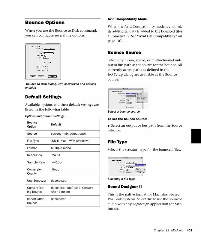
Bounce OptionsWhen you use the Bounce to Disk command, you can configure several file options.
Default Settings
Available options and their default settings are listed in the following table.
Bounce to Disk dialog, with conversion and options enabled
Options and Default Settings
Bounce Option
Default
Source current main output path
File Type SD II (Mac), WAV (Windows)
Format Multiple mono
Resolution 24 bit
Sample Rate 44100
Conversion Quality
Good
Use Squeezer deselected
Convert Dur-ing Bounce
deselected (default is Convert After Bounce)
Import After Bounce
deselected
Avid Compatibility Mode
When the Avid Compatibility mode is enabled, its additional data is added to the bounced files automatically. See “Avid File Compatibility” on page 107.
Bounce Source
Select any mono, stereo, or multi-channel out-put or bus path as the source for the bounce. All currently active paths as defined in the I/O Setup dialog are available as the Bounce Source.
To set the bounce source:
■ Select an output or bus path from the Source Selector.
File Type
Selects the (creator) type for the bounced files.
Sound Designer II
This is the native format for Macintosh-based Pro Tools systems. Select this to use the bounced audio with any Digidesign application for Mac-intosh.
Select a bounce source
Selecting a file type
Chapter 29: Mixdown 401
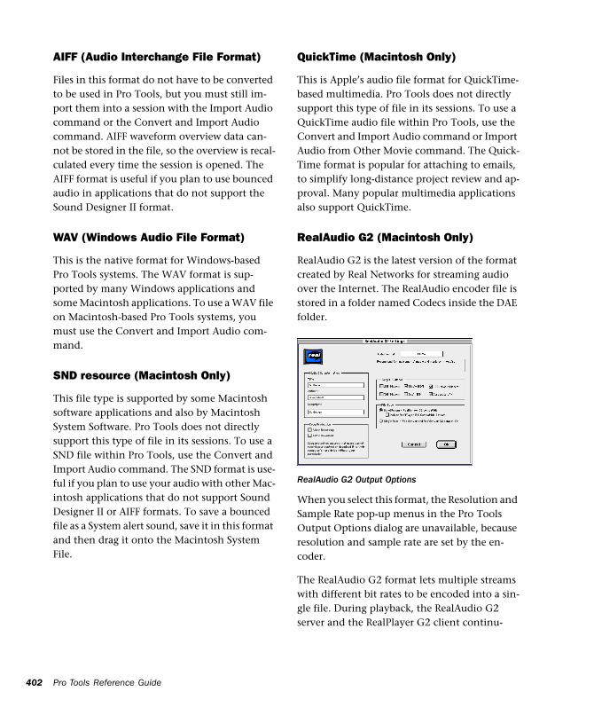
402
AIFF (Audio Interchange File Format)
Files in this format do not have to be converted to be used in Pro Tools, but you must still im-port them into a session with the Import Audio command or the Convert and Import Audio command. AIFF waveform overview data can-not be stored in the file, so the overview is recal-culated every time the session is opened. The AIFF format is useful if you plan to use bounced audio in applications that do not support the Sound Designer II format.
WAV (Windows Audio File Format)
This is the native format for Windows-based Pro Tools systems. The WAV format is sup-ported by many Windows applications and some Macintosh applications. To use a WAV file on Macintosh-based Pro Tools systems, you must use the Convert and Import Audio com-mand.
SND resource (Macintosh Only)
This file type is supported by some Macintosh software applications and also by Macintosh System Software. Pro Tools does not directly support this type of file in its sessions. To use a SND file within Pro Tools, use the Convert and Import Audio command. The SND format is use-ful if you plan to use your audio with other Mac-intosh applications that do not support Sound Designer II or AIFF formats. To save a bounced file as a System alert sound, save it in this format and then drag it onto the Macintosh System File.
Pro Tools Reference Guide
QuickTime (Macintosh Only)
This is Apple’s audio file format for QuickTime-based multimedia. Pro Tools does not directly support this type of file in its sessions. To use a QuickTime audio file within Pro Tools, use the Convert and Import Audio command or Import Audio from Other Movie command. The Quick-Time format is popular for attaching to emails, to simplify long-distance project review and ap-proval. Many popular multimedia applications also support QuickTime.
RealAudio G2 (Macintosh Only)
RealAudio G2 is the latest version of the format created by Real Networks for streaming audio over the Internet. The RealAudio encoder file is stored in a folder named Codecs inside the DAE folder.
When you select this format, the Resolution and Sample Rate pop-up menus in the Pro Tools Output Options dialog are unavailable, because resolution and sample rate are set by the en-coder.
The RealAudio G2 format lets multiple streams with different bit rates to be encoded into a sin-gle file. During playback, the RealAudio G2 server and the RealPlayer G2 client continu-
RealAudio G2 Output Options
ously adjust the bit rate to make the best use of available bandwidth. The RealPlayer G2 is avail-able on the Real Networks website, www.real.com.
When you export or bounce to RealAudio G2 format, you can set the following options:
Media Clip Information Type the title, author, and copyright information for your RealAudio clip. This information is displayed on the Real-Player G2 as the clip plays back.
Copy Protection These settings determine how the clip is handled by the RealPlayer client.
■ To allow RealPlayer Plus users to save your clip using the RealPlayer Plus recording feature, se-lect Allow Recording.
■ To allow RealPlayer users to download your clip to their hard drive, select Allow Download.
If you don’t want to allow RealPlayer users to make copies your clip, deselect both of these op-tions.
Audio Format From the pop-up menu, select the setting that best matches the type of audio you are bouncing. A brief explanation of each for-mat is displayed.
Target Audience Select the connection speed that most users downloading your clip are likely to have. This setting determines the bit rate at which the audio will be encoded. Depending on the file type you choose (see below), you can choose more than one connection speed.
File Type This option determines the compati-bility of the output file with different RealAudio servers and clients.
If you select SureStream, you can select more than one connection speed under Target Audi-ence. With this file type, multiple bit rate streams are encoded into a single output file. Files encoded with the SureStream option are larger than Single Rate files, and can only be played back from G2 servers.
Select the “Include RealPlayer 5.0 Compatible Stream” option to include a backward compati-ble stream that can be played on older version 5.0 RealPlayers. (This backward compatibility is only available for SureStream-encoded files.)
If you select Single Rate, you can only select one connection speed under Target Audience. With this file type, a single stream is encoded into the output file. Files encoded with the Single Rate option can be played back from either a stan-dard web server or a G2 server.
Auditioning RealAudio clips
If you are using Digidesign Sound Drivers and want to use a RealAudio player while running Pro Tools, make sure that Operations > Active in Background is not selected so the player can use the Digidesign hardware.
Chapter 29: Mixdown 403
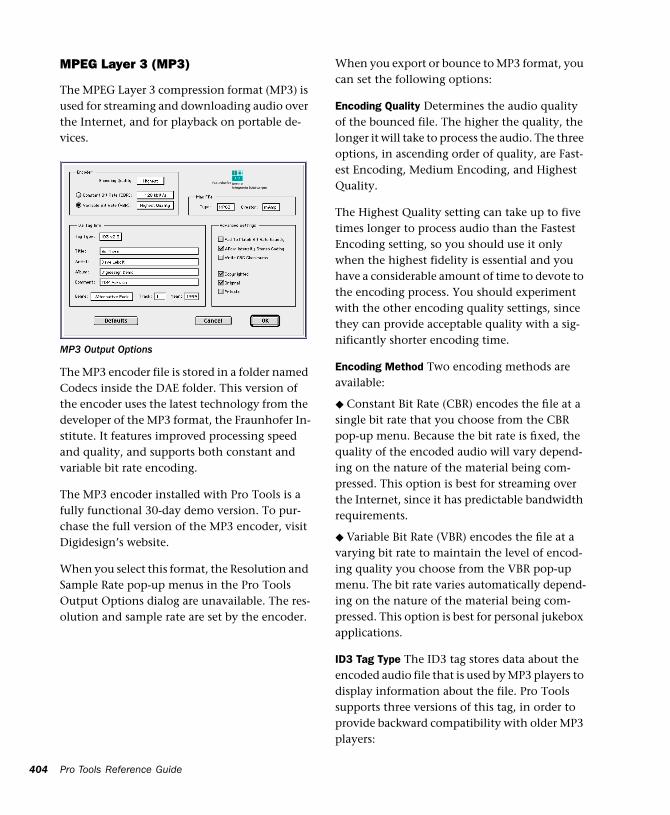
404
MPEG Layer 3 (MP3)
The MPEG Layer 3 compression format (MP3) is used for streaming and downloading audio over the Internet, and for playback on portable de-vices.
The MP3 encoder file is stored in a folder named Codecs inside the DAE folder. This version of the encoder uses the latest technology from the developer of the MP3 format, the Fraunhofer In-stitute. It features improved processing speed and quality, and supports both constant and variable bit rate encoding.
The MP3 encoder installed with Pro Tools is a fully functional 30-day demo version. To pur-chase the full version of the MP3 encoder, visit Digidesign’s website.
When you select this format, the Resolution and Sample Rate pop-up menus in the Pro Tools Output Options dialog are unavailable. The res-olution and sample rate are set by the encoder.
MP3 Output Options
Pro Tools Reference Guide
When you export or bounce to MP3 format, you can set the following options:
Encoding Quality Determines the audio quality of the bounced file. The higher the quality, the longer it will take to process the audio. The three options, in ascending order of quality, are Fast-est Encoding, Medium Encoding, and Highest Quality.
The Highest Quality setting can take up to five times longer to process audio than the Fastest Encoding setting, so you should use it only when the highest fidelity is essential and you have a considerable amount of time to devote to the encoding process. You should experiment with the other encoding quality settings, since they can provide acceptable quality with a sig-nificantly shorter encoding time.
Encoding Method Two encoding methods are available:
◆ Constant Bit Rate (CBR) encodes the file at a single bit rate that you choose from the CBR pop-up menu. Because the bit rate is fixed, the quality of the encoded audio will vary depend-ing on the nature of the material being com-pressed. This option is best for streaming over the Internet, since it has predictable bandwidth requirements.
◆ Variable Bit Rate (VBR) encodes the file at a varying bit rate to maintain the level of encod-ing quality you choose from the VBR pop-up menu. The bit rate varies automatically depend-ing on the nature of the material being com-pressed. This option is best for personal jukebox applications.
ID3 Tag Type The ID3 tag stores data about the encoded audio file that is used by MP3 players to display information about the file. Pro Tools supports three versions of this tag, in order to provide backward compatibility with older MP3 players:
◆ ID3 v1.0: Appears at the end of a streaming MP3 file, therefore tag information is only dis-played after software streaming is finished.
◆ ID3 v1.1: Same as version 1.0 but adds track number information to the tag.
◆ ID3 v2.3: Appears at the front of a streaming MP3 file, therefore tag information is displayed when streaming begins.
ID3 Tag Information Type the title, artist, and other information for the MP3 file. This infor-mation is displayed by many MP3 players.
Genre Choose a genre for the file. This informa-tion is displayed by many MP3 players, and can appear in searchable catalogs and databases.
Track Number If you select ID3 tag type v1.1 or v2.3, you can enter a CD track number for the file. This information is displayed by many MP3 players.
Year Enter a year for the file. This information is displayed by many MP3 players.
Advanced Settings
The options listed under Advanced Settings, un-der normal situations, do not need to be changed from their default values.
Pad To Match Bit Rate Exactly This option de-termines whether MP3 frames are padded to maintain bit rate very precisely. You should only select this option if you need a file with an exact bit rate, for specific applications (such as synchronous transmission over ISDN line).
While ID3 v2.3 is becoming the standard MP3 format, not all MP3 players currently support ID3 v2.3. Contact the developer of your player software for compatibility infor-mation.
Allow Intensity Stereo Coding This option deter-mines whether the encoder takes into account the frequency of a signal when encoding its phase characteristics, allowing for more com-pression at low bit rates. In most cases, you should leave this option selected. However, if you are working with highly phase-dependent material, such as Dolby Surround, you may want to deselect this option.
Write CRC Checksums This option adds error-detection data to the MP3 file. This data is not necessary for most computer and Internet appli-cations, and also takes away from the space available for audio data. Select this option only if you are sure your delivery mode requires error correction.
Copyrighted This option sets a bit in the MP3 data stream to indicate that the audio is copy-righted. Not all MP3 players use this informa-tion. Selecting this option does not guarantee that the audio file will not be copied.
Original This option sets a bit in the MP3 data stream to indicate that the audio is the original media for the track, rather than a copy. This set-ting is not widely used.
Private This option sets a bit in the MP3 data stream that is interpreted differently by various applications. It is not normally used.
Mac File information If you expect your file to be used on a Macintosh, you can enter the Macin-tosh file type and creator. This will allow users to double-click the file to open their MP3 player.
Padding of MP3 frames can cause problems with some versions of Internet streaming software. If your files are destined for desk-top or Internet delivery, do not select this option.
Chapter 29: Mixdown 405
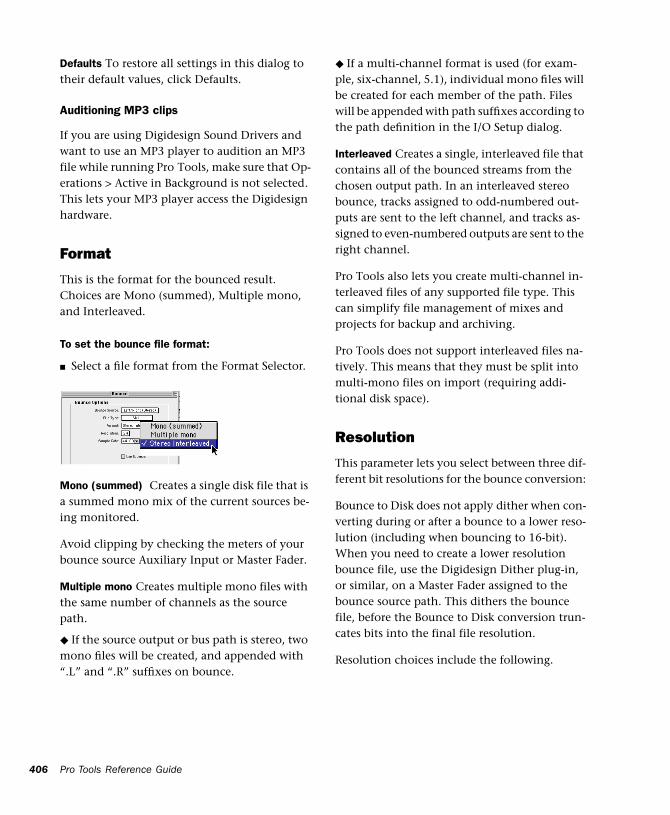
406
Defaults To restore all settings in this dialog to their default values, click Defaults.
Auditioning MP3 clips
If you are using Digidesign Sound Drivers and want to use an MP3 player to audition an MP3 file while running Pro Tools, make sure that Op-erations > Active in Background is not selected. This lets your MP3 player access the Digidesign hardware.
Format
This is the format for the bounced result. Choices are Mono (summed), Multiple mono, and Interleaved.
To set the bounce file format:
■ Select a file format from the Format Selector.
Mono (summed) Creates a single disk file that is a summed mono mix of the current sources be-ing monitored.
Avoid clipping by checking the meters of your bounce source Auxiliary Input or Master Fader.
Multiple mono Creates multiple mono files with the same number of channels as the source path.
◆ If the source output or bus path is stereo, two mono files will be created, and appended with “.L” and “.R” suffixes on bounce.
Pro Tools Reference Guide
◆ If a multi-channel format is used (for exam-ple, six-channel, 5.1), individual mono files will be created for each member of the path. Files will be appended with path suffixes according to the path definition in the I/O Setup dialog.
Interleaved Creates a single, interleaved file that contains all of the bounced streams from the chosen output path. In an interleaved stereo bounce, tracks assigned to odd-numbered out-puts are sent to the left channel, and tracks as-signed to even-numbered outputs are sent to the right channel.
Pro Tools also lets you create multi-channel in-terleaved files of any supported file type. This can simplify file management of mixes and projects for backup and archiving.
Pro Tools does not support interleaved files na-tively. This means that they must be split into multi-mono files on import (requiring addi-tional disk space).
Resolution
This parameter lets you select between three dif-ferent bit resolutions for the bounce conversion:
Bounce to Disk does not apply dither when con-verting during or after a bounce to a lower reso-lution (including when bouncing to 16-bit). When you need to create a lower resolution bounce file, use the Digidesign Dither plug-in, or similar, on a Master Fader assigned to the bounce source path. This dithers the bounce file, before the Bounce to Disk conversion trun-cates bits into the final file resolution.
Resolution choices include the following.
8-bit This resolution is often used in multimedia applications. If the material you are working with is relatively simple, you can use the Pro Tools “Squeezer” feature for optimal results. See “Sample Rate Conversion Quality” on page 407 for details.
16-bit This is the Compact Disc standard bit res-olution.
24-bit If you plan to use the bounced file with a Pro Tools 24 MIX or Pro Tools 24 system, you can take advantage of the greater resolution and headroom afforded by this higher bit rate. You can also archive a master stereo mixdown or bounce audio material at this resolution for fu-ture use on a 24-bit system.
To set the bounce file resolution:
1 Select a bit depth from the Resolution Selec-tor.
Sample Rate
This option lets you save to any of several sam-ple rates.
Sample Rate Conversion Quality
If you choose a sample rate that differs from the original sample rate of the session, the conver-sion options become available. You can config-ure the conversion quality, and schedule con-version to occur during, or after, the bounce. See “Sample Rate Conversion Quality” on page 407 for more information.
The following are the more common sample rates, and their application.
48000 This is the standard sample rate for con-sumer-level DAT decks.
44100 The standard sample rate for compact discs and pro-level DAT decks. It is also used for high-fidelity audio destined for playback on newer Macintosh computers with 16-bit audio playback capability, as well as on Windows computers.
22050 and 11025 Commonly used for lower-fi-delity audio destined for playback on newer Macintosh computers with 16-bit audio play-back capability, as well as on Windows comput-ers.
22254 and 11127 Commonly used for lower-fi-delity audio destined specifically for playback on older Macintosh computers not equipped with 16-bit audio playback capability.
Custom Lets you selects a sample rate other than the choices above.
Other Sample Rates Several of the other avail-able sample rates support pull-up and pull-down rates, or other specialized rates.
Sample Rate Conversion Quality
The Conversion Quality option sets the quality of sample rate conversion used to create the converted file. The higher the quality of sample rate conversion, the longer it takes to convert the file after the bounce has taken place. There are five possible settings, ranging from Low to Tweak-head. For most applications, the Better setting yields satisfactory results.
Processing Resources and Conversion Quality
Because the Best and Tweak-head settings take significantly longer than the others, use them only in cases where the highest fidelity is essen-tial and you have a considerable amount of time to devote to this process.
Chapter 29: Mixdown 407
408
Use Squeezer
The Use Squeezer option uses a proprietary DSP algorithm specifically designed for performing 8-bit conversion of simple source files such as voice-overs. It optimizes the dynamics of the au-dio by preprocessing it using compression, lim-iting, and gating before conversion to 8-bit res-olution. This results in greater apparent loudness in the signal, and improved intelligi-bility. If you are converting a more complex 16-bit audio file to 8-bit resolution, test this option before converting all of your material.
Convert During or After Bounce
The Bounce dialog can perform any conversion options, including sample rate and bit depth conversion, during a bounce or post-bounce.
Convert After Bounce This option automati-cally performs file type, sample rate and bit res-olution conversion on the newly bounced files. The Convert After Bounce option, though more time and storage consuming, offers the highest level of plug-in automation accuracy possible.
Convert During Bounce This option may take less time than Convert After Bounce, but does so at the expense of plug-in automation playback accuracy.
Import Into Session After Bounce
The Import Into Session After Bounce option au-tomatically imports the newly bounced files into the Audio Regions List so you can place them in tracks. If your newly bounced files are split stereo files, they are listed together in the Audio Regions List.
The Import Into Session After Bounce option is only available if the target bit depth for the bounce is the same as the bit depth of the cur-rent session.
Pro Tools Reference Guide
Help
The Help button opens a display-only dialog box that describes the Bounce to Disk features.
Recording a SubmixYou can create a submix with the Bounce to Disk command by muting tracks or bypassing inserts that are not part of the submix group, and se-lecting the part of the session you want to bounce.
You can also create a submix by recording to new tracks. For details, see “Recording to Tracks” on page 399.
To bounce a submix to disk and bring it into the session:
1 Configure your submix using sends, Auxiliary Inputs, and Master Faders. (See “Submixing for Signal Routing and Effects Processing” on page 347.)
2 Do one of the following:
◆ To bounce the entire session, click Return to Zero in the Transport window to go to the be-ginning of the session.
◆ To bounce a portion of the session, enable Link Edit and Timeline, and make a selection in the Edit window.
3 Choose File > Bounce to Disk.
4 Configure bounce options and parameters.
5 Make sure the bit resolution for the bounced file matches the bit resolution of the session.
6 Select the Import into Session After Bounce option.
7 Click Bounce.
8 Select a destination for the new audio file, en-ter a name, and click Save.
Pro Tools bounces are done in real time, so you hear audio playback of your mix during the bounce process. You can not adjust controls during a Bounce to Disk.
To bring bounced files back into tracks:
1 Do one of the following:
◆ If the newly bounced audio was automatically imported into the session, drag the new files from the Audio Regions List to existing tracks in your session.
◆ If the bounced files are not available in the Audio Regions List, import them into the ses-sion by choosing File > Convert and Import Au-dio.
◆ If you are placing multiple files of a mutli-channel track or file, keep channels in phase with each other by Shift-selecting them in the Regions List, and dragging them simultaneously into existing tracks of the right format.
2 When working with stereo tracks, set the pan controls hard left/right.
3 Mute or turn off the voices of original source tracks so that you don’t double monitor your audio material.
4 Click Play in the Transport window to hear the results of the bounce.
Final MixdownIn final mixdown, you create a mix that in-cludes all your edits, automation, and effects processing.
To bounce a final mix to disk:
1 Adjust track output levels, finalize any mix au-tomation, and choose an automation mode for each track in the session.
2 Adjust any real-time plug-in and effects set-tings and automation for each track in the ses-sion.
3 Make sure that all of the tracks you want to in-clude in the bounce are audible (not muted or inactive).
4 Assign the output of each of the tracks you want to include in your bounce to the same out-put path.
5 Do one of the following:
■ To bounce the entire session, click Return to Zero in the Transport window to go to the be-ginning of the session.
■ To bounce a portion of the session, enable Link Edit and Timeline and make a selection in the Edit window.
1 Choose File > Bounce to Disk.
2 Choose the source path you want to bounce.
3 Configure other Bounce to Disk parameters as appropriate. See “Bounce Options” on page 401.
4 Click Bounce.
5 Select a destination for the new audio file, en-ter a name, and click Save.
Chapter 29: Mixdown 409
410
MasteringIn the final mastering process, you might record directly to disk, to a DVD or CD recorder, to a stereo mastering recorder, or directly to a multi-track recorder for surround mixes.
Once you have created a master of your session, you can transfer it to a portable medium for du-plication. You can transfer the master file to CD, DAT or 8 mm DDP tape to be used as a master for pressing compact discs.
Mastering to a Digital Recorder
Although it is usually best to master sessions di-rectly to hard disk, Pro Tools also lets you mas-ter digitally, direct to any AES/EBU or S/PDIF-equipped digital recorder such as a DAT deck.
24-bit Input and Output with Pro Tools 24 MIX and Pro Tools 24 Systems
Pro Tools 24 MIX and Pro Tools 24 are full 24-bit audio recording and mixing environments, supporting record, playback, mixing, and pro-cessing of 24-bit audio files. You can record to and from other 24-bit recording systems with-out any bit-depth conversion.
Mastering and Audio Compression
Although audio compression is often an indis-pensable tool in analog recording, it can present problems in the digital domain. If you compress an input signal at a very high ratio, you create a signal that contains a much higher overall power level compared to its transients. By re-cording a number of such signals at the highest possible level on multiple tracks, you create a scenario that is more likely to clip the mixed output signal.
Pro Tools Reference Guide
High-power compressed signals, when mixed together, create an extremely high-level output. This output may rise above the full-code level, resulting in clipping.
To avoid this problem, watch the overall level of your program material—use a meter on a Master Fader, or use an external mastering deck’s meters to help avoid clipping. If you are master-ing to hard disk, avoid mixing full-code audio signals together at unity or “0” level, as this in-variably causes clipping.
Mastering and Error-Correcting Media
Random access media (such as hard disks, opti-cal cartridges, Bernoulli cartridges or WORM drives) can produce a true digital copy of your data, because every bit value is maintained. Se-quential media (such as DAT tapes) use error correction schemes to fix the occasional bad data that is received in a digital transfer. These corrections are deviations from the actual data, and with successive reproductions, represent a subtle form of generation loss.
You can avoid this loss by creating and main-taining masters on random-access digital media (such as a hard drive) and transferring them to sequential digital media (such as DAT tapes) only as needed.
To configure Pro Tools for direct digital stereo mastering:
1 Connect your digital recorder to your system’s digital outputs.
2 In Pro Tools set the appropriate digital format and output from the Hardware Setup or Play-back Engine dialog.
3 On your digital recorder, choose the appropri-ate digital format for the connections.
4 In Pro Tools, set all audio tracks you want to your master outputs 1–2 path.
5 Click Return to Zero in the Transport window to go to the beginning of the session.
6 Press Record on your digital recorder.
7 Start playback of your session.
8 When your session has finished playing, stop the digital recorder.
Chapter 29: Mixdown 411

412
Pro Tools Reference Guide
Part VII: Surround
413

414
Chapter 30: Surround Concepts
Pro Tools MIX and MIXplus systems support multi-channel mixing for surround sound.
How to Use These Chapters
This part of the guide describes multi-channel mixing for surround sound with Pro Tools. These sections supplement the basic Pro Tools information provided elsewhere in the Pro Tools Reference Guide.
If you are new to surround mixing, read the re-maining sections of this chapter for an introduc-tion to surround terminology and concepts.
If you already have experience with surround mixing, mastering, and monitoring, these sec-tions can be skipped. Operational instructions for Pro Tools surround features begin in Chapter 31, “Pro Tools Setup for Surround.”
Mixing Formats and Surround Formats When running Pro Tools version 5.1 or later with the SurroundMixer plug-in, Pro Tools MIX and MIXplus systems let you mix in 3- to 8-channel formats, in addition to standard mono and stereo.
Supported mixing formats include, Mono, Stereo, LCR, Quad, LCRS, 5.1, 6.1 and 7.1, letting you mix in any multi-channel format needed for most surround formats.
Surround formats include Dolby Surround (Pro-Logic) and Dolby Digital, DTS, and SDDS. Pro Tools does not provide its own surround for-mat processing, and requires appropriate plug-ins (such as Dolby SurroundTools™) or hard-ware to provide surround encoding and decod-ing.
Chapter 30: Surround Concepts 415
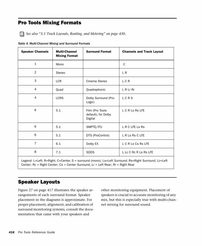
416
Pro Tools Mixing Formats
Pro Tools Reference Guide
See also “5.1 Track Layouts, Routing, and Metering” on page 430.
Table 4. Multi-Channel Mixing and Surround Formats
Speaker Layouts
Speaker Channels Multi-Channel Mixing Format
Surround Format Channels and Track Layout
1 Mono C
2 Stereo L R
3 LCR Cinema Stereo L C R
4 Quad Quadraphonic L R Lr Rr
4 LCRS Dolby Surround (Pro-Logic)
L C R S
6 5.1 Film (Pro Tools default), for Dolby Digital
L C R Ls Rs LFE
6 5.1 SMPTE/ITU L R C LFE Ls Rs
6 5.1 DTS (ProControl) L R Ls Rs C LFE
7 6.1 Dolby EX L C R Ls Cs Rs LFE
8 7.1 SDDS L Lc C Rc R Ls Rs LFE
Legend: L=Left; R=Right; C=Center, S = surround (mono); Ls=Left Surround; Rs=Right Surround; Lc=Left Center; Rc = Right Center; Cs = Center Surround; Lr = Left Rear; Rr = Right Rear
Figure 27 on page 417 illustrates the speaker ar-rangements of each surround format. Speaker placement in the diagrams is approximate. For proper placement, alignment, and calibration of surround monitoring systems, consult the docu-mentation that came with your speakers and
other monitoring equipment. Placement of speakers is crucial to accurate monitoring of any mix, but this is especially true with multi-chan-nel mixing for surround sound.
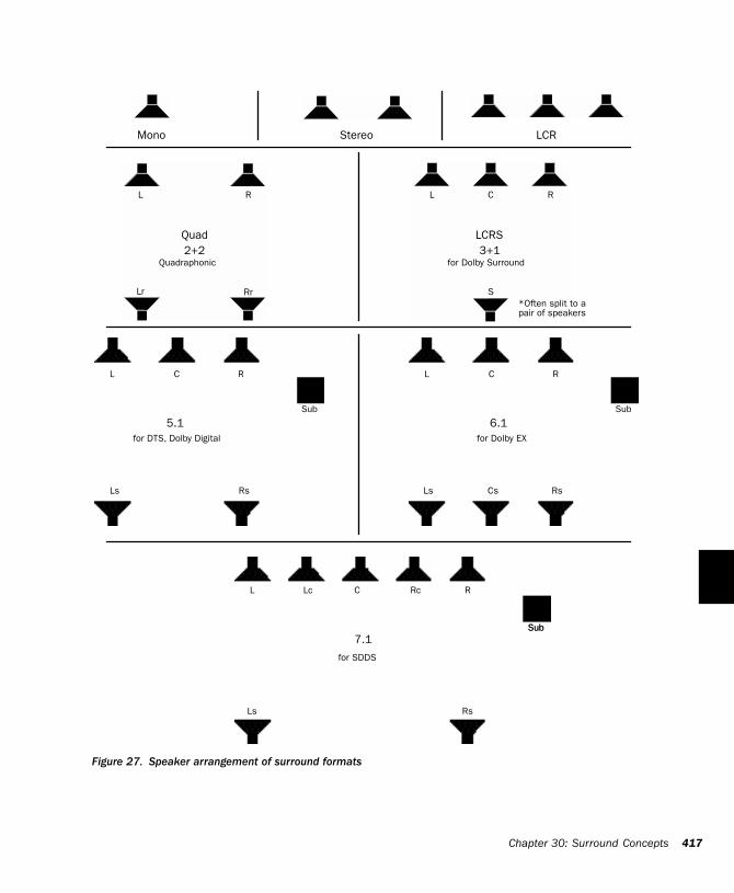
Figure 27. Speaker arrangement of surround formats
for Dolby Surround
for DTS, Dolby Digital
for SDDS
for Dolby EX
Quadraphonic
Mono Stereo LCR
Quad LCRS
5.1 6.1
7.1
L R L C R
Lr Rr S
Rs
CL R RCL
RsCsLs
RCL
Ls
RsLs
Lc Rc
SubSub
SubSub
*Often split to a pair of speakers
3+12+2
Chapter 30: Surround Concepts 417
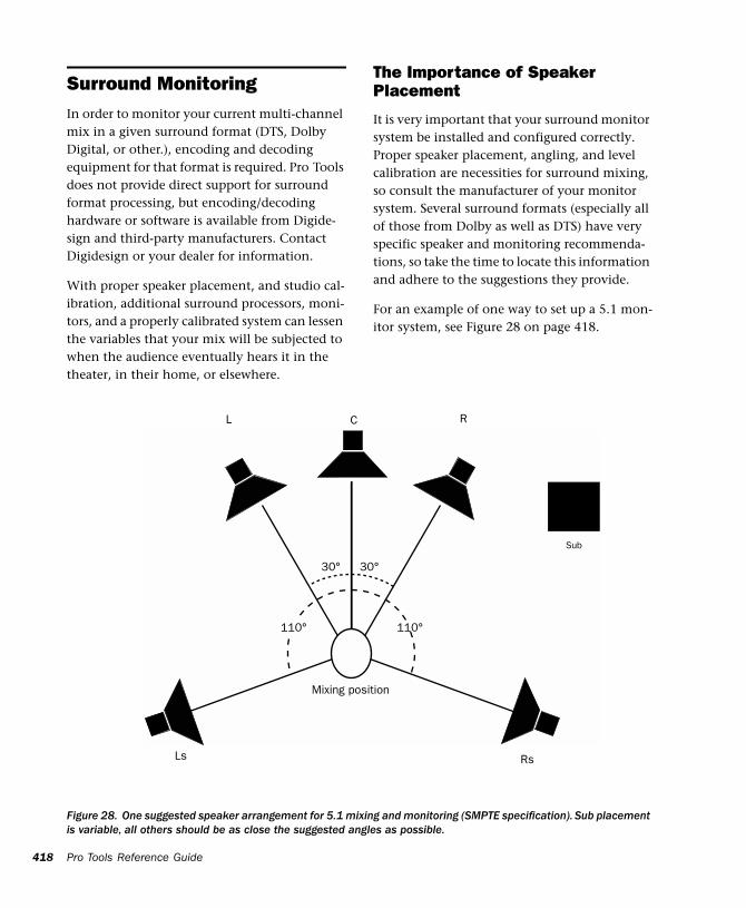
418
Surround Monitoring In order to monitor your current multi-channel mix in a given surround format (DTS, Dolby Digital, or other.), encoding and decoding equipment for that format is required. Pro Tools does not provide direct support for surround format processing, but encoding/decoding hardware or software is available from Digide-sign and third-party manufacturers. Contact Digidesign or your dealer for information.
With proper speaker placement, and studio cal-ibration, additional surround processors, moni-tors, and a properly calibrated system can lessen the variables that your mix will be subjected to when the audience eventually hears it in the theater, in their home, or elsewhere.
Pro Tools Reference Guide
The Importance of Speaker Placement
It is very important that your surround monitor system be installed and configured correctly. Proper speaker placement, angling, and level calibration are necessities for surround mixing, so consult the manufacturer of your monitor system. Several surround formats (especially all of those from Dolby as well as DTS) have very specific speaker and monitoring recommenda-tions, so take the time to locate this information and adhere to the suggestions they provide.
For an example of one way to set up a 5.1 mon-itor system, see Figure 28 on page 418.
Figure 28. One suggested speaker arrangement for 5.1 mixing and monitoring (SMPTE specification). Sub placement is variable, all others should be as close the suggested angles as possible.
110°
30°
110°
30°
Mixing position
Sub
L C R
Ls Rs
Calibrated Surround Monitoring
In any professional applications, one of the most important things you can do is to calibrate not just Pro Tools but also your monitoring sys-tem and other equipment.
For example, many post production facilities calibrate their Pro Tools audio interfaces for -20 dB = 0 VU. Once Pro Tools hardware has been calibrated to unity gain, the monitoring system can be adjusted to account for anomalies in the room acoustics, speaker placement, and other variables.
Calibrating your Pro Tools system involves at-tenuating the input and output stages of your system. Settings and reference level vary accord-ing to the applicable standards of the current project.
Calibrating your Studio The first task for sur-round mixing should be getting your monitor speakers in proper position, alignment and cali-bration for accurate listening and mixing.
Speaker position and alignment will vary ac-cording to each installation, and is very specific for different speakers, manufacturers, and for each surround format. Instructions for optimal speaker location should have been provided with the speaker and monitor system, so consult the documentation provided by its manufac-turer.
Speaker calibration makes sure that your system plays back at accurately balanced levels. This lets you compensate for any variances in speaker position, alignment or performance.
Calibrating in Pro Tools is explained in the TDM Installation Guide.
Formats and TerminologyMulti-channel mixing formats are referred to numerically, such as “5.1” and “7.1.” These numbers describe the number and type of out-put (speaker) channels required for that format. Other formats are referred to by their track lay-out (such LCRS, and LCR).
Surround formats are referred to by their devel-oper and product name, such as Dolby Surround (or ProLogic), Dolby Digital, DTS, Dolby E, and others. Each surround format requires you to mix in a compatible mixing format. For exam-ple, both Dolby Digital and DTS are “5.1 sur-round formats.”
The standards for each format include more than just the number of speakers. Formats also may require specific track layout and filtering for the various channels. For example, the sur-round channel in Dolby Surround is band lim-ited 100 Hz to 7 kHz.
Surround formats also increase the importance of phase, balance, and sound placement due to the various ways in which multi-channel mixes can be encoded, decoded, compressed, or ma-trixed. Many publications are available on these subjects. For a listing of several sources of sur-round format information, see “Where to Get More Information on Surround Technology” on page 421.
LCRS for Dolby Surround
Dolby Surround (ProLogic) is a four-channel for-mat that is one of the most widely accepted con-sumer surround formats.
Chapter 30: Surround Concepts 419
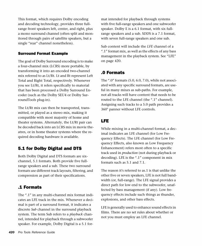
420
This format, which requires Dolby encoding and decoding technology, provides three full-range front speakers left, center, and right, plus a mono surround channel (often split and mon-itored through pairs of satellite speakers, but a single “rear” channel nonetheless).
Surround Format Example
The goal of Dolby Surround encoding is to make a four-channel mix (LCRS) more portable, by transforming it into an encoded two-channel mix referred to as Lt/Rt. Lt and Rt represent Left Total and Right Total, respectively. Whenever you see Lt/Rt, it refers specifically to material that has been processed a Dolby Surround En-coder (such as the Dolby SEU4 or Dolby Sur-roundTools plug-in).
The Lt/Rt mix can then be transported, trans-mitted, or played as a stereo mix, making it compatible with most majority of home and theater systems. Alternately, the Lt/Rt pair can be decoded back into an LCRS mix in movie the-atres, or in home theater systems where the re-quired decoding hardware is available.
5.1 for Dolby Digital and DTS
Both Dolby Digital and DTS formats are six-channel, 5.1 formats. Both provide five full-range speakers and a sub. These two surround formats use different track layouts, filtering, and compression as part of their specifications.
.1 Formats
The “.1” in any multi-channel mix format indi-cates an LFE track in the mix. Whenever a deci-mal is part of a surround format, it indicates a discrete Sub channel in the surround playback system. The term Sub refers to a playback chan-nel, intended for playback through a subwoofer speaker. For example, Dolby Digital is a 5.1 for-
Pro Tools Reference Guide
mat intended for playback through systems with five full-range speakers and one subwoofer speaker. Dolby E is a 6.1 format, with six full-range speakers and a sub. SDDS is a 7.1 format, with seven full-range speakers and one sub.
Sub content will include the LFE channel of a “.1” format mix, as well as the effects of any bass management in the playback system. See “LFE” on page 420.
.0 Formats
The “.0” formats (5.0, 6.0, 7.0), while not associ-ated with any specific surround formats, are use-ful in many mixes as sub-paths. For example, not all tracks will have content that needs to be routed to the LFE channel (the “.1” channel). Assigning such tracks to a 5.0 path provides a 360° panner without LFE controls.
LFE
While mixing in a multi-channel format, a dec-imal indicates an LFE channel (for Low Fre-quency Effects). The LFE channel (for Low Fre-quency Effects, also known as Low Frequency Enhancement) refers most often to a specific track used in production (not during playback or decoding). LFE is the “.1” component in mix formats such as 5.1 and 7.1.
The reason it's referred to as.1 is that unlike the other five or seven speakers, LFE is not full band-width (or, full-range). The LFE signal provides a direct path for low end to the subwoofer, unaf-fected by bass management (if any). Low fre-quency effects include such things as thunder, explosions, and other bass effects.
LFE is generally used to enhance sound effects in films. There are no set rules about whether or not you must employ an LFE channel.
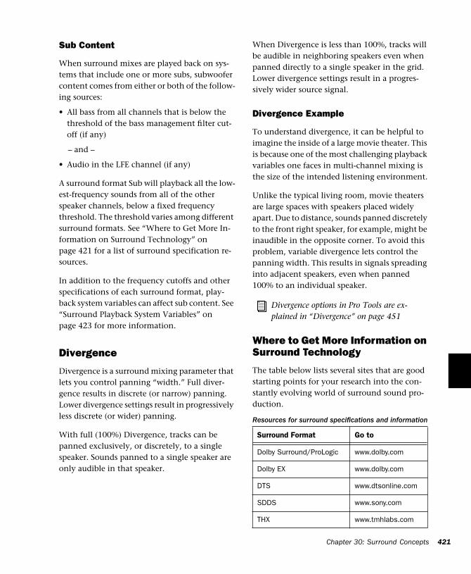
Sub Content
When surround mixes are played back on sys-tems that include one or more subs, subwoofer content comes from either or both of the follow-ing sources:
• All bass from all channels that is below the threshold of the bass management filter cut-off (if any)
– and –
• Audio in the LFE channel (if any)
A surround format Sub will playback all the low-est-frequency sounds from all of the other speaker channels, below a fixed frequency threshold. The threshold varies among different surround formats. See “Where to Get More In-formation on Surround Technology” on page 421 for a list of surround specification re-sources.
In addition to the frequency cutoffs and other specifications of each surround format, play-back system variables can affect sub content. See “Surround Playback System Variables” on page 423 for more information.
Divergence
Divergence is a surround mixing parameter that lets you control panning “width.” Full diver-gence results in discrete (or narrow) panning. Lower divergence settings result in progressively less discrete (or wider) panning.
With full (100%) Divergence, tracks can be panned exclusively, or discretely, to a single speaker. Sounds panned to a single speaker are only audible in that speaker.
When Divergence is less than 100%, tracks will be audible in neighboring speakers even when panned directly to a single speaker in the grid. Lower divergence settings result in a progres-sively wider source signal.
Divergence Example
To understand divergence, it can be helpful to imagine the inside of a large movie theater. This is because one of the most challenging playback variables one faces in multi-channel mixing is the size of the intended listening environment.
Unlike the typical living room, movie theaters are large spaces with speakers placed widely apart. Due to distance, sounds panned discretely to the front right speaker, for example, might be inaudible in the opposite corner. To avoid this problem, variable divergence lets control the panning width. This results in signals spreading into adjacent speakers, even when panned 100% to an individual speaker.
Where to Get More Information on Surround Technology
The table below lists several sites that are good starting points for your research into the con-stantly evolving world of surround sound pro-duction.
Divergence options in Pro Tools are ex-plained in “Divergence” on page 451
Resources for surround specifications and information
Surround Format Go to
Dolby Surround/ProLogic www.dolby.com
Dolby EX www.dolby.com
DTS www.dtsonline.com
SDDS www.sony.com
THX www.tmhlabs.com
Chapter 30: Surround Concepts 421
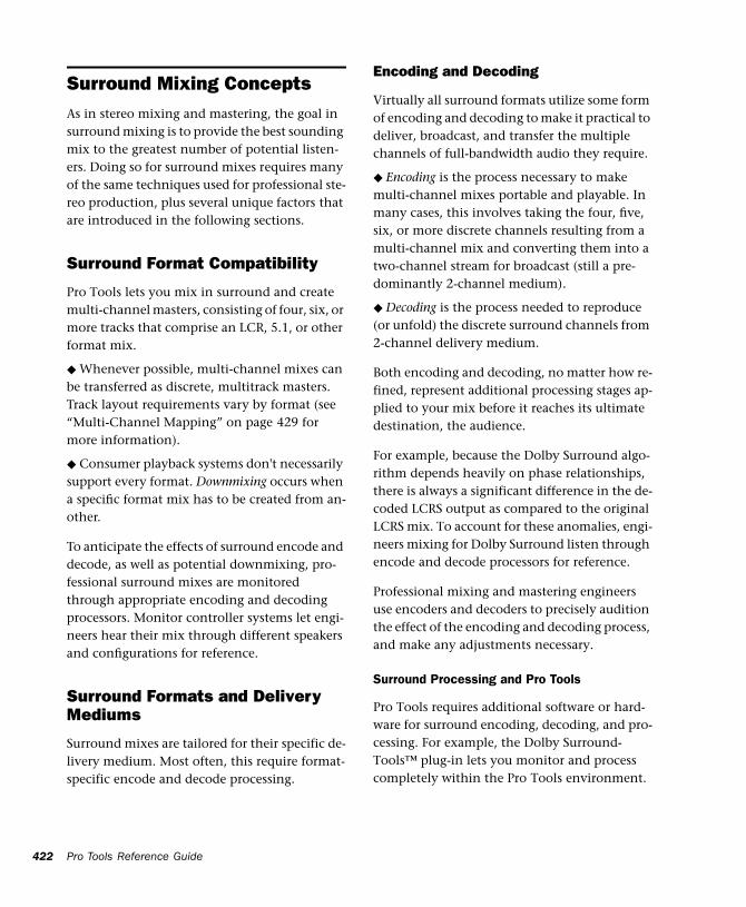
422
Surround Mixing ConceptsAs in stereo mixing and mastering, the goal in surround mixing is to provide the best sounding mix to the greatest number of potential listen-ers. Doing so for surround mixes requires many of the same techniques used for professional ste-reo production, plus several unique factors that are introduced in the following sections.
Surround Format Compatibility
Pro Tools lets you mix in surround and create multi-channel masters, consisting of four, six, or more tracks that comprise an LCR, 5.1, or other format mix.
◆ Whenever possible, multi-channel mixes can be transferred as discrete, multitrack masters. Track layout requirements vary by format (see “Multi-Channel Mapping” on page 429 for more information).
◆ Consumer playback systems don't necessarily support every format. Downmixing occurs when a specific format mix has to be created from an-other.
To anticipate the effects of surround encode and decode, as well as potential downmixing, pro-fessional surround mixes are monitored through appropriate encoding and decoding processors. Monitor controller systems let engi-neers hear their mix through different speakers and configurations for reference.
Surround Formats and Delivery Mediums
Surround mixes are tailored for their specific de-livery medium. Most often, this require format-specific encode and decode processing.
Pro Tools Reference Guide
Encoding and Decoding
Virtually all surround formats utilize some form of encoding and decoding to make it practical to deliver, broadcast, and transfer the multiple channels of full-bandwidth audio they require.
◆ Encoding is the process necessary to make multi-channel mixes portable and playable. In many cases, this involves taking the four, five, six, or more discrete channels resulting from a multi-channel mix and converting them into a two-channel stream for broadcast (still a pre-dominantly 2-channel medium).
◆ Decoding is the process needed to reproduce (or unfold) the discrete surround channels from 2-channel delivery medium.
Both encoding and decoding, no matter how re-fined, represent additional processing stages ap-plied to your mix before it reaches its ultimate destination, the audience.
For example, because the Dolby Surround algo-rithm depends heavily on phase relationships, there is always a significant difference in the de-coded LCRS output as compared to the original LCRS mix. To account for these anomalies, engi-neers mixing for Dolby Surround listen through encode and decode processors for reference.
Professional mixing and mastering engineers use encoders and decoders to precisely audition the effect of the encoding and decoding process, and make any adjustments necessary.
Surround Processing and Pro Tools
Pro Tools requires additional software or hard-ware for surround encoding, decoding, and pro-cessing. For example, the Dolby Surround-Tools™ plug-in lets you monitor and process completely within the Pro Tools environment.
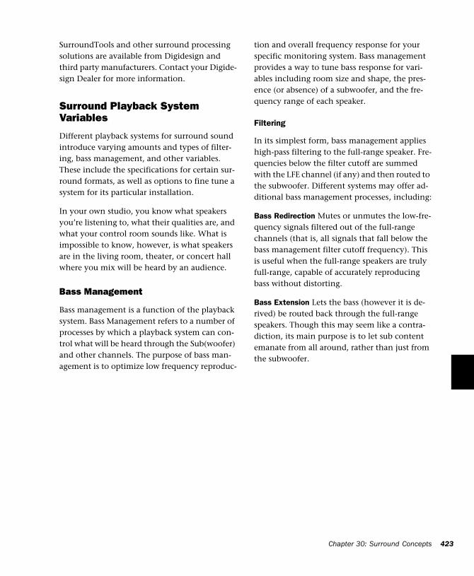
SurroundTools and other surround processing solutions are available from Digidesign and third party manufacturers. Contact your Digide-sign Dealer for more information.
Surround Playback System Variables
Different playback systems for surround sound introduce varying amounts and types of filter-ing, bass management, and other variables. These include the specifications for certain sur-round formats, as well as options to fine tune a system for its particular installation.
In your own studio, you know what speakers you’re listening to, what their qualities are, and what your control room sounds like. What is impossible to know, however, is what speakers are in the living room, theater, or concert hall where you mix will be heard by an audience.
Bass Management
Bass management is a function of the playback system. Bass Management refers to a number of processes by which a playback system can con-trol what will be heard through the Sub(woofer) and other channels. The purpose of bass man-agement is to optimize low frequency reproduc-
tion and overall frequency response for your specific monitoring system. Bass management provides a way to tune bass response for vari-ables including room size and shape, the pres-ence (or absence) of a subwoofer, and the fre-quency range of each speaker.
Filtering
In its simplest form, bass management applies high-pass filtering to the full-range speaker. Fre-quencies below the filter cutoff are summed with the LFE channel (if any) and then routed to the subwoofer. Different systems may offer ad-ditional bass management processes, including:
Bass Redirection Mutes or unmutes the low-fre-quency signals filtered out of the full-range channels (that is, all signals that fall below the bass management filter cutoff frequency). This is useful when the full-range speakers are truly full-range, capable of accurately reproducing bass without distorting.
Bass Extension Lets the bass (however it is de-rived) be routed back through the full-range speakers. Though this may seem like a contra-diction, its main purpose is to let sub content emanate from all around, rather than just from the subwoofer.
Chapter 30: Surround Concepts 423

424
Pro Tools Reference Guide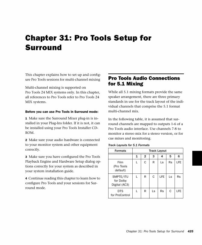
Chapter 31: Pro Tools Setup for Surround
This chapter explains how to set up and config-ure Pro Tools sessions for multi-channel mixing
Multi-channel mixing is supported on Pro Tools 24 MIX systems only. In this chapter, all references to Pro Tools refer to Pro Tools 24 MIX systems.
Before you can use Pro Tools in Surround mode:
1 Make sure the Surround Mixer plug-in is in-stalled in your Plug-Ins folder. If it is not, it can be installed using your Pro Tools Installer CD-ROM.
2 Make sure your audio hardware is connected to your monitor system and other equipment correctly.
3 Make sure you have configured the Pro Tools Playback Engine and Hardware Setup dialog op-tions correctly for your system as described in your system installation guide.
4 Continue reading this chapter to learn how to configure Pro Tools and your sessions for Sur-round mode.
Pro Tools Audio Connections for 5.1 MixingWhile all 5.1 mixing formats provide the same speaker arrangement, there are three primary standards in use for the track layout of the indi-vidual channels that comprise the 5.1 format multi-channel mix.
In the following table, it is assumed that sur-round channels are mapped to outputs 1-6 of a Pro Tools audio interface. Use channels 7-8 to monitor a stereo mix for a stereo version, or for cue mixes and monitoring.
Track Layouts for 5.1 Formats
Formats Track Layout
1 2 3 4 5 6
Film (Pro Tools default)
L C R Ls Rs LFE
SMPTE/ITU for Dolby
Digital (AC3)
L R C LFE Ls Rs
DTSfor ProControl
L R Ls Rs C LFE
Chapter 31: Pro Tools Setup for Surround 425
426
To connect your audio interfaces for 5.1 format mixing and monitoring:
1 Determine the 5.1 format and track layout you want to use.
2 Connect the output channels of your audio interface to the corresponding input channels of your monitoring system according to the as-signments listed in Table on page 425.
Configuring Pro Tools for Multi-Channel SessionsConfiguring Pro Tools and sessions for multi-channel mixing can be done in any or all of the following ways:
New Sessions
By creating a new session and choosing a sur-round mix I/O Settings file as the default I/O Setup. (See “New Sessions and I/O Settings” on page 426.)
Remixing Sessions in Surround
By importing a surround mix I/O Settings file into the I/O Setup dialog, multi-channel paths can be made available in any stereo (or other format) session. You can then reassign track routing from the original stereo paths to multi-channel paths. Inactive and active paths sim-plify reassignment. (See “Importing Multi-Channel I/O Setups” on page 428.)
If you use ProControl and its monitoring section, see the ProControl Addendum for Pro Tools 5.1 for more information.
Pro Tools Reference Guide
Custom Paths
You can customize and redefine existing paths in the I/O Setup dialog. For more information, see “Custom Multi-Channel Paths” on page 428.
Importing Tracks
By importing tracks into a session, you can add only the tracks and media, but also the associ-ated paths and track assignments. Tracks retain their paths and assignments, which are added to the current session. Active and inactive status is determined by available system resources. After importing tracks, you can use the I/O Setup dia-log to configure main and sub-paths for require-ments of the session. For more information, see “Importing Tracks from Other Sessions” on page 94.
New Sessions and I/O Settings
When you create a new session, you can specify a surround format that you want to use as your I/O Setup. Default path configurations are pro-vided as I/O Settings files, for stereo and sur-round mixing.
Once you create the new session, you can create and import tracks, import audio, and assign sig-nal routing to set up your mix.
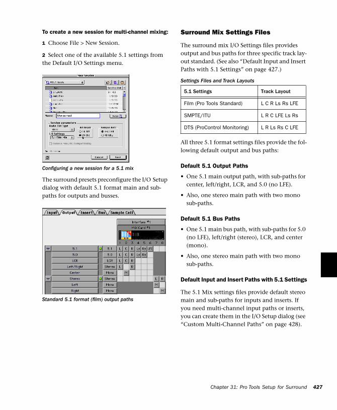
To create a new session for multi-channel mixing:
1 Choose File > New Session.
2 Select one of the available 5.1 settings from the Default I/O Settings menu.
The surround presets preconfigure the I/O Setup dialog with default 5.1 format main and sub-paths for outputs and busses.
Configuring a new session for a 5.1 mix
Standard 5.1 format (film) output paths
Surround Mix Settings Files
The surround mix I/O Settings files provides output and bus paths for three specific track lay-out standard. (See also “Default Input and Insert Paths with 5.1 Settings” on page 427.)
All three 5.1 format settings files provide the fol-lowing default output and bus paths:
Default 5.1 Output Paths
• One 5.1 main output path, with sub-paths for center, left/right, LCR, and 5.0 (no LFE).
• Also, one stereo main path with two mono sub-paths.
Default 5.1 Bus Paths
• One 5.1 main bus path, with sub-paths for 5.0 (no LFE), left/right (stereo), LCR, and center (mono).
• Also, one stereo main path with two mono sub-paths.
Default Input and Insert Paths with 5.1 Settings
The 5.1 Mix settings files provide default stereo main and sub-paths for inputs and inserts. If you need multi-channel input paths or inserts, you can create them in the I/O Setup dialog (see “Custom Multi-Channel Paths” on page 428).
Settings Files and Track Layouts
5.1 Settings Track Layout
Film (Pro Tools Standard) L C R Ls Rs LFE
SMPTE/ITU L R C LFE Ls Rs
DTS (ProControl Monitoring) L R Ls Rs C LFE
Chapter 31: Pro Tools Setup for Surround 427
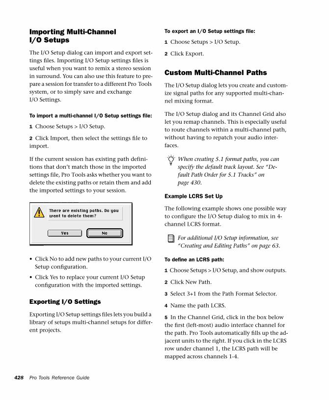
428
Importing Multi-Channel I/O Setups
The I/O Setup dialog can import and export set-tings files. Importing I/O Setup settings files is useful when you want to remix a stereo session in surround. You can also use this feature to pre-pare a session for transfer to a different Pro Tools system, or to simply save and exchange I/O Settings.
To import a multi-channel I/O Setup settings file:
1 Choose Setups > I/O Setup.
2 Click Import, then select the settings file to import.
If the current session has existing path defini-tions that don’t match those in the imported settings file, Pro Tools asks whether you want to delete the existing paths or retain them and add the imported settings to your session.
• Click No to add new paths to your current I/O Setup configuration.
• Click Yes to replace your current I/O Setup configuration with the imported settings.
Exporting I/O Settings
Exporting I/O Setup settings files lets you build a library of setups multi-channel setups for differ-ent projects.
Pro Tools Reference Guide
To export an I/O Setup settings file:
1 Choose Setups > I/O Setup.
2 Click Export.
Custom Multi-Channel Paths
The I/O Setup dialog lets you create and custom-ize signal paths for any supported multi-chan-nel mixing format.
The I/O Setup dialog and its Channel Grid also let you remap channels. This is especially useful to route channels within a multi-channel path, without having to repatch your audio inter-faces.
Example LCRS Set Up
The following example shows one possible way to configure the I/O Setup dialog to mix in 4-channel LCRS format.
To define an LCRS path:
1 Choose Setups > I/O Setup, and show outputs.
2 Click New Path.
3 Select 3+1 from the Path Format Selector.
4 Name the path LCRS.
5 In the Channel Grid, click in the box below the first (left-most) audio interface channel for the path. Pro Tools automatically fills up the ad-jacent units to the right. If you click in the LCRS row under channel 1, the LCRS path will be mapped across channels 1-4.
When creating 5.1 format paths, you can specify the default track layout. See “De-fault Path Order for 5.1 Tracks” on page 430.
For additional I/O Setup information, see “Creating and Editing Paths” on page 63.
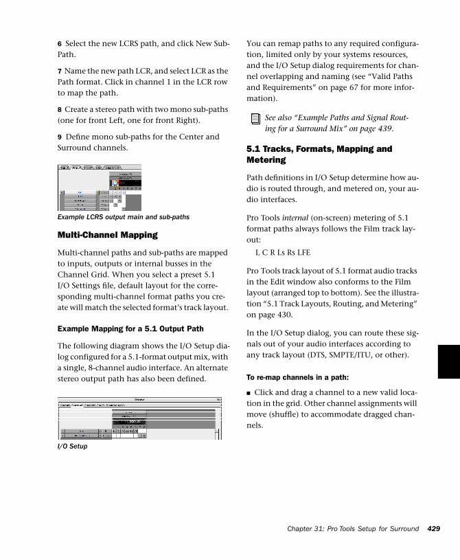
6 Select the new LCRS path, and click New Sub-Path.
7 Name the new path LCR, and select LCR as the Path format. Click in channel 1 in the LCR row to map the path.
8 Create a stereo path with two mono sub-paths (one for front Left, one for front Right).
9 Define mono sub-paths for the Center and Surround channels.
Multi-Channel Mapping
Multi-channel paths and sub-paths are mapped to inputs, outputs or internal busses in the Channel Grid. When you select a preset 5.1 I/O Settings file, default layout for the corre-sponding multi-channel format paths you cre-ate will match the selected format’s track layout.
Example Mapping for a 5.1 Output Path
The following diagram shows the I/O Setup dia-log configured for a 5.1-format output mix, with a single, 8-channel audio interface. An alternate stereo output path has also been defined.
Example LCRS output main and sub-paths
I/O Setup
You can remap paths to any required configura-tion, limited only by your systems resources, and the I/O Setup dialog requirements for chan-nel overlapping and naming (see “Valid Paths and Requirements” on page 67 for more infor-mation).
5.1 Tracks, Formats, Mapping and Metering
Path definitions in I/O Setup determine how au-dio is routed through, and metered on, your au-dio interfaces.
Pro Tools internal (on-screen) metering of 5.1 format paths always follows the Film track lay-out:
L C R Ls Rs LFE
Pro Tools track layout of 5.1 format audio tracks in the Edit window also conforms to the Film layout (arranged top to bottom). See the illustra-tion “5.1 Track Layouts, Routing, and Metering” on page 430.
In the I/O Setup dialog, you can route these sig-nals out of your audio interfaces according to any track layout (DTS, SMPTE/ITU, or other).
To re-map channels in a path:
■ Click and drag a channel to a new valid loca-tion in the grid. Other channel assignments will move (shuffle) to accommodate dragged chan-nels.
See also “Example Paths and Signal Rout-ing for a Surround Mix” on page 439.
Chapter 31: Pro Tools Setup for Surround 429
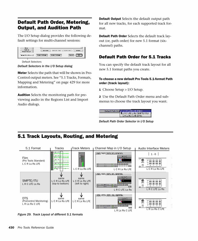
430
Default Path Order, Metering, Output, and Audition PathThe I/O Setup dialog provides the following de-fault settings for multi-channel sessions:
Meter Selects the path that will be shown in Pro-Control output meters. See “5.1 Tracks, Formats, Mapping and Metering” on page 429 for more information.
Audition Selects the monitoring path for pre-viewing audio in the Regions List and Import Audio dialogs.
Default Selectors in the I/O Setup dialog
Default Selectors
Pro Tools Reference Guide
Default Output Selects the default output path for all new tracks, for each supported track for-mat.
Default Path Order Selects the default track lay-out (or, path order) for new 5.1 format (six-channel) paths.
Default Path Order for 5.1 Tracks
You can specify the default track layout for all new 5.1 format paths you create.
To choose a new default Pro Tools 5.1-format Path order (track layout):
1 Choose Setup > I/O Setup.
2 Use the Default Path Order menu and sub-menus to choose the track layout you want.
Default Path Order Selector in I/O Setup
5.1 Track Layouts, Routing, and Metering
Figure 29. Track Layout of different 5.1 formats
Audio Interface MetersChannel Map in I/O Setup5.1 Format
Film
SMPTE/ITU
DTS
L C R Ls Rs LFE
L R C LFE Ls Rs
L R Ls Rs C LFE
L C R Ls Rs LFE
Track Meters Tracks
L C R Ls Rs LFE(top to bottom)
same
L C R Ls Rs LFEsame
same
same
L C R Ls Rs LFE(left to right)
L C R Ls Rs LFE
(Pro Tools Standard)
(ProControl Monitoring)
L C R Ls Rs LFE
L R C LFE Ls Rs
L R Ls Rs C LFE
L C R Ls Rs LFE
L R C LFE Ls Rs
L R Ls Rs C LFE
1 - 6
Chapter 32: Multi-Channel Tracks and Signal Routing
Surround sessions typically include a combina-tion of mono, stereo, and multi-channel audio tracks, Auxiliary Inputs, and Master Faders, bus-ses and inserts.
Once the appropriate I/O Setup has been im-ported or configured, any audio track can be mixed in multi-channel for surround using Pro Tools mixing features.
Multi-channel I/O and signal routing is deter-mined by the paths defined in the I/O Setup di-alog.
Multi-Channel QuickStartThe following is an overview of how to get started mixing in multi-channel for surround in Pro Tools.
To mix in multi-channel:
1 Open any stereo Pro Tools session to remix it in surround. (You can also create new, empty surround sessions. See “New Sessions and I/O Settings” on page 426.)
2 Configure the I/O Setup dialog with multi-channel inputs, outputs, busses, and inserts, as needed. (See “Configuring Pro Tools for Multi-Channel Sessions” on page 426.)
3 Create new tracks and assign track outputs and sends to your multi-channel paths. Config-ure signal routing as needed for submixing, bus-sing, processing, and monitoring. For tracks that do not need to panned in 360°, place them in the mix using sub-paths and signal routing.(See “Multi-Channel Signal Routing” on page 434.)
4 Pan in surround using the multi-channel Track and Send windows. (Mixing and panning for surround is explained in Chapter 33, “Sur-round Panning and Mixing.”)
Chapter 32: Multi-Channel Tracks and Signal Routing 431
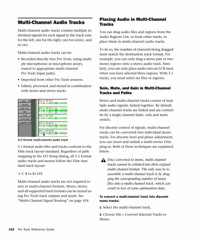
432
Multi-Channel Audio TracksMulti-channel audio tracks contain multiple in-dividual signals for each signal in the track (one for the left, one for the right, one for center, and so on).
Multi-channel audio tracks can be:
• Recorded directly into Pro Tools, using multi-ple microphones or microphone arrays, routed to appropriate multi-channel Pro Tools Input paths.
• Imported from other Pro Tools sessions.
• Edited, processed, and mixed in combination with mono and stereo tracks.
5.1 format audio files and tracks conform to the Film track layout standard. Regardless of path mapping in the I/O Setup dialog, all 5.1 format audio tracks and meters follow the Film stan-dard track layout:
L C R Ls Rs LFE
Multi-channel audio tracks are not required to mix in multi-channel formats. Mono, stereo, and all supported track formats can be mixed us-ing Pro Tools track outputs and sends. See “Multi-Channel Signal Routing” on page 434.
5.0 format multi-channel audio track
Pro Tools Reference Guide
Placing Audio in Multi-Channel Tracks
You can drag audio files and regions from the Audio Regions List, or from other tracks, to place them in multi-channel audio tracks.
To do so, the number of channels being dragged must match the destination track format. For example, you can only drag a stereo pair or two mono regions onto a stereo audio track. Simi-larly, you can only place audio into an LCR track when you have selected three regions. With 5.1 tracks, you must select six files or regions.
Solo, Mute, and Gain in Multi-Channel Tracks and Paths
Stereo and multi-channel tracks consist of mul-tiple audio signals, linked together. By default, multi-channel tracks are linked and are control-ler by a single channel fader, solo and mute switch.
For discrete control of signals, multi-channel tracks can be converted into individual mono tracks. For discrete level and phase adjustment, you can insert and unlink a multi-mono Trim plug-in. Both of these techniques are explained below.
To convert a multi-channel track into discrete mono tracks:
1 Select the multi-channel track.
2 Choose File > Convert Selected Tracks to Mono.
Once converted to mono, multi-channel tracks cannot be relinked into their original multi-channel format. The only way to re-assemble a multi-channel track is by drag-ging the corresponding number of mono files into a multi-channel track, which can result in loss of some automation data.
To have discrete control of gain on individual channels of a multi-channel track:
1 Insert a multi-mono Trim plug-in on the multi-channel track.
2 Unlink the Trim plug-in by clicking the Link icon so that it is unlit.
3 Use the Channel Selector to display the con-trols you want to edit, and adjust the gain.
Track and Output Formats
When you create new tracks, you specify mono, stereo, or a supported multi-channel format for the new tracks.
In the Mix and Edit windows, the track format is always visible by the number of track meters contained in its fader strip (a single meter for mono tracks, a pair for stereo tracks, and so on).
Assigning track output determines the format of that output. For example, a mono track always has a single track meter, even when assigned to a stereo output path. If that same mono track is assigned to a 5.1 output path, it's output will be split among those six output channels, depend-ing on the position of its panner.
Changing Format
Changing the output format for a given track has several effects:
• The panner that appears in the track will change to reflect the new output format
◆ It may be necessary for one or more pan re-lated automation playlists to be created or de-leted.
See “Linking and Unlinking Controls on Multi-Mono Plug-Ins” on page 436 for more information.
Because changing the output format has these effects, a warning dialog appears whenever you change the output format of a track to a format of fewer channels. Specifically, this will occur whenever automation playlists will have to be deleted.
Multiple Output Assignments and Track Format
When a track is assigned to more than one path of differing formats, the main output for that track will match the format of the assigned path with the greatest number of channels.
Multiple Outputs and Automation Playlists
When a track has multiple output assignments, Pro Tools sorts panning data appropriately for each assigned path. For example, if you assign a mono track to a stereo path and a 5.1 path si-multaneously, that track will have a 5.1 panner in the Mix or Edit window. When you pan the track, Pro Tools interprets the 5.1 panning moves into stereo panning moves (by ignoring any front--to-rear moves, in this example).
This provides a type of parallel mixing. You can create a variety of mixes of differing formats all at the same time by routing your elements to multiple paths.
Command-Control-click any control in a Output window to show its automation playlist.
Chapter 32: Multi-Channel Tracks and Signal Routing 433
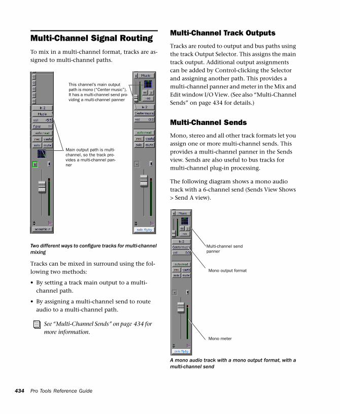
434
Multi-Channel Signal RoutingTo mix in a multi-channel format, tracks are as-signed to multi-channel paths.
Tracks can be mixed in surround using the fol-lowing two methods:
• By setting a track main output to a multi-channel path.
• By assigning a multi-channel send to route audio to a multi-channel path.
Two different ways to configure tracks for multi-channel mixing
See “Multi-Channel Sends” on page 434 for more information.
Main output path is multi-channel, so the track pro-vides a multi-channel pan-ner
This channel’s main output path is mono (“Center music”). It has a multi-channel send pro-viding a multi-channel panner
Pro Tools Reference Guide
Multi-Channel Track Outputs
Tracks are routed to output and bus paths using the track Output Selector. This assigns the main track output. Additional output assignments can be added by Control-clicking the Selector and assigning another path. This provides a multi-channel panner and meter in the Mix and Edit window I/O View. (See also “Multi-Channel Sends” on page 434 for details.)
Multi-Channel Sends
Mono, stereo and all other track formats let you assign one or more multi-channel sends. This provides a multi-channel panner in the Sends view. Sends are also useful to bus tracks for multi-channel plug-in processing.
The following diagram shows a mono audio track with a 6-channel send (Sends View Shows > Send A view).
A mono audio track with a mono output format, with a multi-channel send
Multi-channel send panner
Mono meter
Mono output format
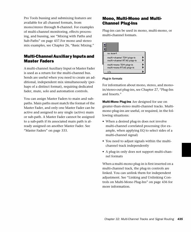
Pro Tools bussing and submixing features are available for all channel formats, from mono/stereo through 8-channel. For examples of multi-channel monitoring, effects process-ing, and bussing, see “Mixing with Paths and Sub-Paths” on page 437.For mono and stereo mix examples, see Chapter 26, “Basic Mixing.”
Multi-Channel Auxiliary Inputs and Master Faders
A multi-channel Auxiliary Input or Master Fader is used as a return for the multi-channel bus. Sends are useful when you need to create an ad-ditional, independent mix simultaneously (per-haps of a distinct format), requiring dedicated fader, mute, solo and automation controls.
You can assign Master Faders to main and sub-paths. Main paths must match the format of the Master Fader, and only one Master Fader can be active and assigned to any single (active) main or sub-path. A Master Fader cannot be assigned to a sub-path if its associated main path is al-ready assigned on another Master Fader. See “Master Faders” on page 333.
Mono, Multi-Mono and Multi-Channel Plug-Ins
Plug-ins can be used in mono, multi-mono, or multi-channel formats.
For information about mono, stereo, and mono-in/stereo-out plug-ins, see Chapter 27, “Plug-Ins and Inserts.”
Multi-Mono Plug-Ins Are designed for use on greater-than-stereo multi-channel tracks. Multi-mono plug-ins are useful, or required, in the fol-lowing situations:
• When a desired plug-in does not involve multi-channel correlated processing (for ex-ample, when applying EQ to select sides of a multi-channel signal)
• You need to adjust signals within the multi-channel track independently
• A plug-in only does not support multi-chan-nel formats
When a multi-mono plug-in is first inserted on a multi-channel track, the plug-in controls are linked. You can unlink them for independent adjustment. See “Linking and Unlinking Con-trols on Multi-Mono Plug-Ins” on page 436 for more information.
Plug-in formats
Chapter 32: Multi-Channel Tracks and Signal Routing 435
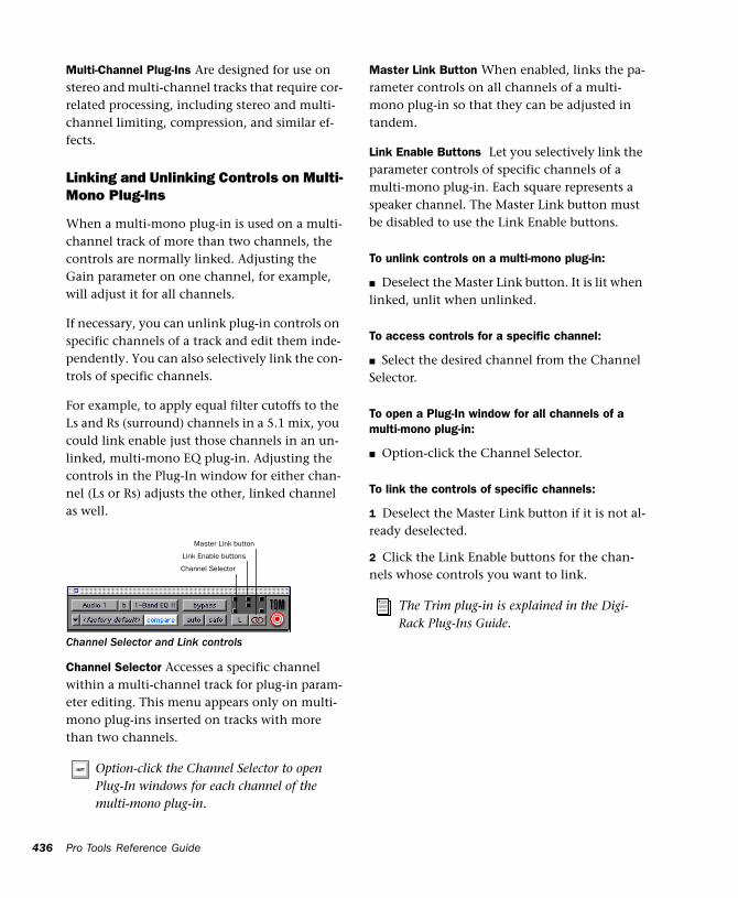
436
Multi-Channel Plug-Ins Are designed for use on stereo and multi-channel tracks that require cor-related processing, including stereo and multi-channel limiting, compression, and similar ef-fects.
Linking and Unlinking Controls on Multi-Mono Plug-Ins
When a multi-mono plug-in is used on a multi-channel track of more than two channels, the controls are normally linked. Adjusting the Gain parameter on one channel, for example, will adjust it for all channels.
If necessary, you can unlink plug-in controls on specific channels of a track and edit them inde-pendently. You can also selectively link the con-trols of specific channels.
For example, to apply equal filter cutoffs to the Ls and Rs (surround) channels in a 5.1 mix, you could link enable just those channels in an un-linked, multi-mono EQ plug-in. Adjusting the controls in the Plug-In window for either chan-nel (Ls or Rs) adjusts the other, linked channel as well.
Channel Selector Accesses a specific channel within a multi-channel track for plug-in param-eter editing. This menu appears only on multi-mono plug-ins inserted on tracks with more than two channels.
Channel Selector and Link controls
Option-click the Channel Selector to open Plug-In windows for each channel of the multi-mono plug-in.
Channel Selector
Link Enable buttons
Master Link button
Pro Tools Reference Guide
Master Link Button When enabled, links the pa-rameter controls on all channels of a multi-mono plug-in so that they can be adjusted in tandem.
Link Enable Buttons Let you selectively link the parameter controls of specific channels of a multi-mono plug-in. Each square represents a speaker channel. The Master Link button must be disabled to use the Link Enable buttons.
To unlink controls on a multi-mono plug-in:
■ Deselect the Master Link button. It is lit when linked, unlit when unlinked.
To access controls for a specific channel:
■ Select the desired channel from the Channel Selector.
To open a Plug-In window for all channels of a multi-mono plug-in:
■ Option-click the Channel Selector.
To link the controls of specific channels:
1 Deselect the Master Link button if it is not al-ready deselected.
2 Click the Link Enable buttons for the chan-nels whose controls you want to link.
The Trim plug-in is explained in the Digi-Rack Plug-Ins Guide.
Paths in Surround MixesBecause Pro Tools provides a flexible routing and submixing environment, you can maximize your system’s available resources by first identi-fying the elements that you want to pan dynam-ically and those that can be placed in certain channels only. (See “Mixing with Paths and Sub-Paths” on page 437 for an explanation of this concept.)
Once you have identified these elements in your session, you can use a combination of main and sub-path assignments, and multi-channel pan-ning. Figure 30 on page 438 shows an example session.
Mixing with Paths and Sub-Paths
It is rare that every track needs to be “flown” (ac-tively panned in between more than a pair of speakers). In most situations, certain elements are placed in certain speakers and remain there, providing the foundation for a mix.
Figure 30 on page 438 illustrates an example of how panning and signal routing can be com-bined in a multi-channel mix. The following sections show you how to organize your session and signal routing to maximize the available re-sources.
See “Extending Stereo Mixing Conventions to Surround Mixing” on page 438 for re-lated information.
When to Assign Multi-Channel Outputs
■ Assign 5.1 paths only to those tracks that need to be panned to all six channels.
For example, a sound effects track with a jet fly-over should be assigned a 5.1 path to be able to “fly” the sound from front-to-back. In a music mix, fly a solo instrument or make a synth pad swirl around the room as a special effect.
Elements that need to be heard in all speakers si-multaneously can also be assigned to the multi-channel output, whether or not they need ac-tive panning in the sound field.
When to Use Sub-Paths
■ To help simplify large sessions, try to use sub-paths to route static (or, stationary) elements di-rectly to the output channel or channels.
For example, film dialog is often mixed to the center channel to anchor this essential sound el-ement to the visual element (the picture). In-stead of assigning a six-channel panner to dia-log tracks and panning it to the center channel only, you can route dialog track’s main output to a mono (Center) sub-path. This may be un-avoidable in some sessions, such as a scene in which every sound needs to fly or move in the 360° sound field. This is more likely to be the ex-ception, however, because many elements of a mix will not need to be moving between speak-ers.
Chapter 32: Multi-Channel Tracks and Signal Routing 437
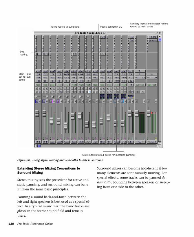
438
Pro Tools Reference GuideFigure 30. Using signal routing and sub-paths to mix in surround
Tracks routed to sub-paths Tracks panned in 3DAuxiliary Inputs and Master Fadersrouted to main paths
Busrouting
Main out-put to sub-paths
Main outputs to 5.1 paths for surround panning
Extending Stereo Mixing Conventions to Surround Mixing
Stereo mixing sets the precedent for active and static panning, and surround mixing can bene-fit from the same basic principles.
Panning a sound back-and-forth between the left and right speakers is best used as a special ef-fect. In a typical music mix, the basic tracks are placed in the stereo sound field and remain there.
Surround mixes can become incoherent if too many elements are continuously moving, For special effects, some tracks can be panned dy-namically, bouncing between speakers or sweep-ing from one side to the other.
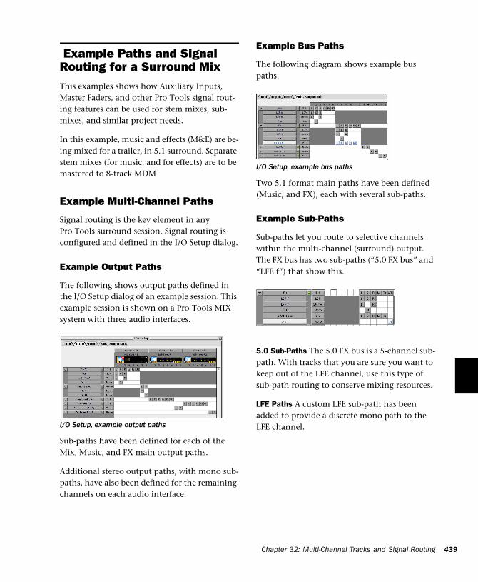
Example Paths and Signal Routing for a Surround MixThis examples shows how Auxiliary Inputs, Master Faders, and other Pro Tools signal rout-ing features can be used for stem mixes, sub-mixes, and similar project needs.
In this example, music and effects (M&E) are be-ing mixed for a trailer, in 5.1 surround. Separate stem mixes (for music, and for effects) are to be mastered to 8-track MDM
Example Multi-Channel Paths
Signal routing is the key element in any Pro Tools surround session. Signal routing is configured and defined in the I/O Setup dialog.
Example Output Paths
The following shows output paths defined in the I/O Setup dialog of an example session. This example session is shown on a Pro Tools MIX system with three audio interfaces.
Sub-paths have been defined for each of the Mix, Music, and FX main output paths.
Additional stereo output paths, with mono sub-paths, have also been defined for the remaining channels on each audio interface.
I/O Setup, example output paths
Example Bus Paths
The following diagram shows example bus paths.
Two 5.1 format main paths have been defined (Music, and FX), each with several sub-paths.
Example Sub-Paths
Sub-paths let you route to selective channels within the multi-channel (surround) output. The FX bus has two sub-paths (“5.0 FX bus” and “LFE f”) that show this.
5.0 Sub-Paths The 5.0 FX bus is a 5-channel sub-path. With tracks that you are sure you want to keep out of the LFE channel, use this type of sub-path routing to conserve mixing resources.
LFE Paths A custom LFE sub-path has been added to provide a discrete mono path to the LFE channel.
I/O Setup, example bus paths
Chapter 32: Multi-Channel Tracks and Signal Routing 439
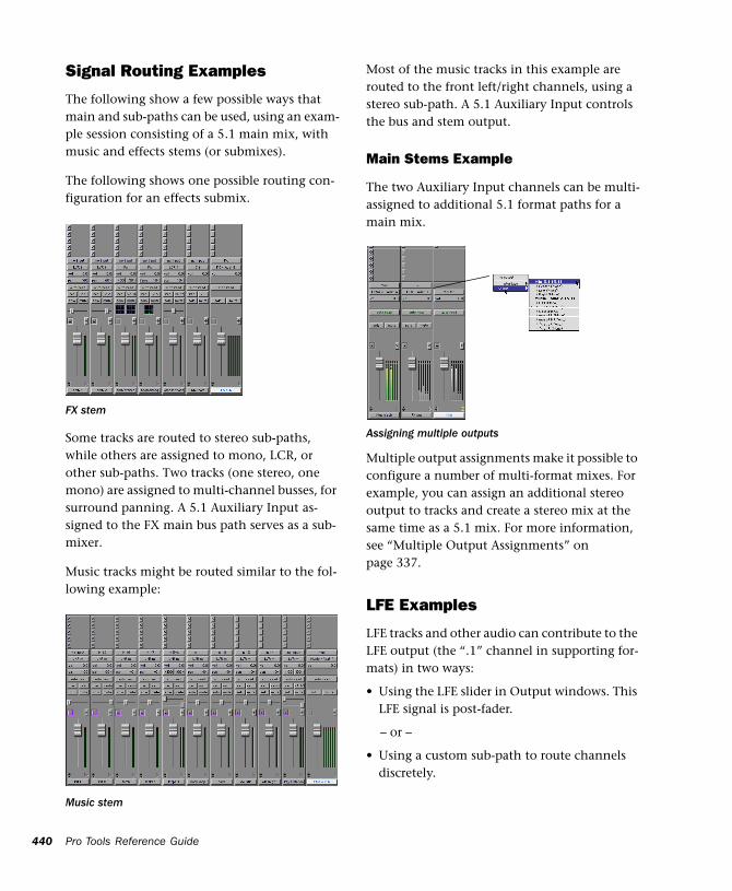
440
Signal Routing Examples
The following show a few possible ways that main and sub-paths can be used, using an exam-ple session consisting of a 5.1 main mix, with music and effects stems (or submixes).
The following shows one possible routing con-figuration for an effects submix.
Some tracks are routed to stereo sub-paths, while others are assigned to mono, LCR, or other sub-paths. Two tracks (one stereo, one mono) are assigned to multi-channel busses, for surround panning. A 5.1 Auxiliary Input as-signed to the FX main bus path serves as a sub-mixer.
Music tracks might be routed similar to the fol-lowing example:
FX stem
Music stem
Pro Tools Reference Guide
Most of the music tracks in this example are routed to the front left/right channels, using a stereo sub-path. A 5.1 Auxiliary Input controls the bus and stem output.
Main Stems Example
The two Auxiliary Input channels can be multi-assigned to additional 5.1 format paths for a main mix.
Multiple output assignments make it possible to configure a number of multi-format mixes. For example, you can assign an additional stereo output to tracks and create a stereo mix at the same time as a 5.1 mix. For more information, see “Multiple Output Assignments” on page 337.
LFE Examples
LFE tracks and other audio can contribute to the LFE output (the “.1” channel in supporting for-mats) in two ways:
• Using the LFE slider in Output windows. This LFE signal is post-fader.
– or –
• Using a custom sub-path to route channels discretely.
Assigning multiple outputs
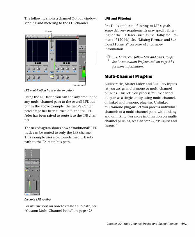
The following shows a channel Output window, sending and metering to the LFE channel.
Using the LFE fader, you can add any amount of any multi-channel path to the overall LFE out-put.In the above example, the track’s Center percentage has been turned off, and the LFE fader has been raised to route it to the LFE chan-nel.
The next diagram shows how a “traditional” LFE track can be routed to only the LFE channel. This example uses a custom-defined LFE sub-path to the FX main bus path.
For instructions on how to create a sub-path, see “Custom Multi-Channel Paths” on page 428.
LFE contribution from a stereo output
Discrete LFE routing
LFE fader
Aux LFE meter
LFE and Filtering
Pro Tools applies no filtering to LFE signals. Some delivery requirements may specify filter-ing for the LFE track (such as the Dolby require-ment of 120 Hz). See “Mixing Formats and Sur-round Formats” on page 415 for more information.
Multi-Channel Plug-Ins
Audio tracks, Master Faders and Auxiliary Inputs let you assign multi-mono or multi-channel plug-ins. This lets you process multi-channel outputs as a single entity using multi-channel, or linked multi-mono, plug-ins. Unlinked multi-mono plug-ins let you process individual channels of a multi-channel path, with linking and unlinking. For more information on multi-channel plug-ins, see Chapter 27, “Plug-Ins and Inserts.”
LFE faders can follow Mix and Edit Groups. See “Automation Preferences” on page 374 for more information.
Chapter 32: Multi-Channel Tracks and Signal Routing 441

442
Pro Tools Reference Guide
Chapter 33: Surround Panning and Mixing
This chapter explains how to pan and mix in surround with Pro Tools.
Before you can pan a track in surround, it must be assigned to an appropriate multi-channel output or bus path.
The I/O Setup dialog defines the bussing and output architecture of the Pro Tools multi-chan-nel surround mixer. If you have not already done so, it is recommended that you become fa-miliar with main and sub-paths and the I/O Setup dialog before starting multi-channel Pro Tools projects.
See Chapter 31, “Pro Tools Setup for Sur-round” for more information on multi-channel configurations and I/O Setup op-tions. For multichannel signal routing, see Chapter 32, “Multi-Channel Tracks and Signal Routing.”
Introduction to Pro Tools Surround PanningThere are four different track panning methods available:
• In the Edit window, using the reduced-height Panner grid in the I/O View
• In the Mix window, using the reduced-height Panner grid
• In the Output window, using the full-size Panner Grid
• Through pan automation editing
Control surfaces provide additional panning op-tions. Refer to the documentation for your con-trol surface for more information.
Mix and Edit Window Panner Grids
In the Mix and Edit window, multi-channel panner grids are displayed on tracks that have multi-channel track or send output assign-ments.
Chapter 33: Surround Panning and Mixing 443
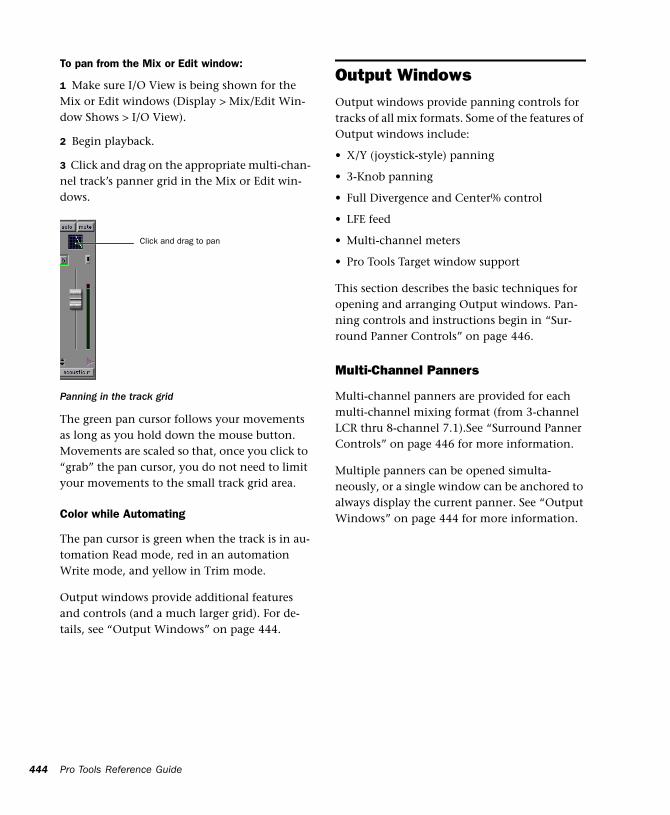
444
To pan from the Mix or Edit window:
1 Make sure I/O View is being shown for the Mix or Edit windows (Display > Mix/Edit Win-dow Shows > I/O View).
2 Begin playback.
3 Click and drag on the appropriate multi-chan-nel track’s panner grid in the Mix or Edit win-dows.
The green pan cursor follows your movements as long as you hold down the mouse button. Movements are scaled so that, once you click to “grab” the pan cursor, you do not need to limit your movements to the small track grid area.
Color while Automating
The pan cursor is green when the track is in au-tomation Read mode, red in an automation Write mode, and yellow in Trim mode.
Output windows provide additional features and controls (and a much larger grid). For de-tails, see “Output Windows” on page 444.
Panning in the track grid
Click and drag to pan
Pro Tools Reference Guide
Output WindowsOutput windows provide panning controls for tracks of all mix formats. Some of the features of Output windows include:
• X/Y (joystick-style) panning
• 3-Knob panning
• Full Divergence and Center% control
• LFE feed
• Multi-channel meters
• Pro Tools Target window support
This section describes the basic techniques for opening and arranging Output windows. Pan-ning controls and instructions begin in “Sur-round Panner Controls” on page 446.
Multi-Channel Panners
Multi-channel panners are provided for each multi-channel mixing format (from 3-channel LCR thru 8-channel 7.1).See “Surround Panner Controls” on page 446 for more information.
Multiple panners can be opened simulta-neously, or a single window can be anchored to always display the current panner. See “Output Windows” on page 444 for more information.
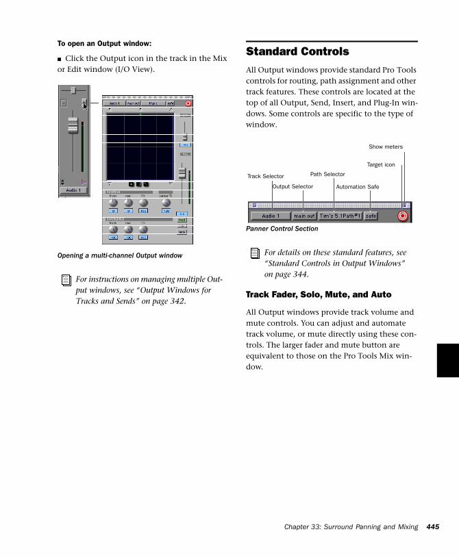
To open an Output window:
■ Click the Output icon in the track in the Mix or Edit window (I/O View).
Opening a multi-channel Output window
For instructions on managing multiple Out-put windows, see “Output Windows for Tracks and Sends” on page 342.
Standard ControlsAll Output windows provide standard Pro Tools controls for routing, path assignment and other track features. These controls are located at the top of all Output, Send, Insert, and Plug-In win-dows. Some controls are specific to the type of window.
Track Fader, Solo, Mute, and Auto
All Output windows provide track volume and mute controls. You can adjust and automate track volume, or mute directly using these con-trols. The larger fader and mute button are equivalent to those on the Pro Tools Mix win-dow.
Panner Control Section
For details on these standard features, see “Standard Controls in Output Windows” on page 344.
Track Selector
Output Selector
Path Selector
Target icon
Show meters
Automation Safe
Chapt
er 33: Surround P a nning and Mixing 445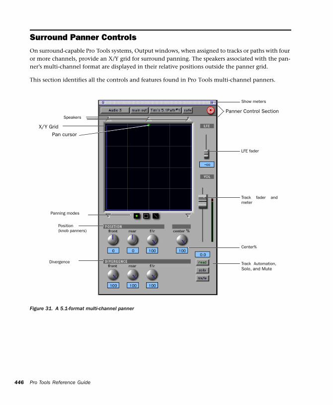
446
Surround Panner ControlsOn surround-capable Pro Tools systems, Output windows, when assigned to tracks or paths with four or more channels, provide an X/Y grid for surround panning. The speakers associated with the pan-ner’s multi-channel format are displayed in their relative positions outside the panner grid.
This section identifies all the controls and features found in Pro Tools multi-channel panners.
Pro Tools Reference Guide
Figure 31. A 5.1-format multi-channel panner
X/Y Grid
Panner Control Section
LFE fader
Track fader andmeter
Position (knob panners)
Divergence
Pan cursor
Panning modes
Track Automation,Solo, and Mute
Speakers
Center%
Show meters
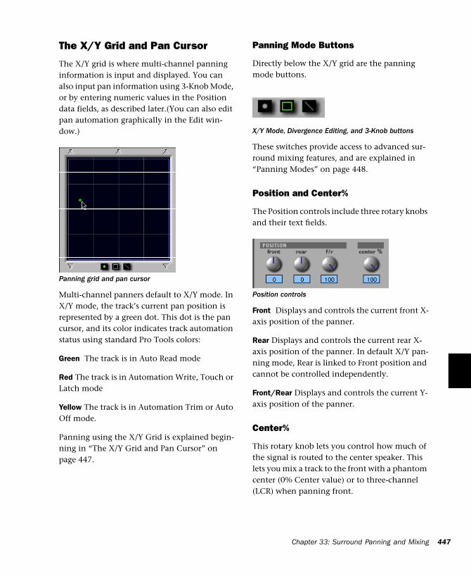
The X/Y Grid and Pan Cursor
The X/Y grid is where multi-channel panning information is input and displayed. You can also input pan information using 3-Knob Mode, or by entering numeric values in the Position data fields, as described later.(You can also edit pan automation graphically in the Edit win-dow.)
Multi-channel panners default to X/Y mode. In X/Y mode, the track’s current pan position is represented by a green dot. This dot is the pan cursor, and its color indicates track automation status using standard Pro Tools colors:
Green The track is in Auto Read mode
Red The track is in Automation Write, Touch or Latch mode
Yellow The track is in Automation Trim or Auto Off mode.
Panning using the X/Y Grid is explained begin-ning in “The X/Y Grid and Pan Cursor” on page 447.
Panning grid and pan cursor
Panning Mode Buttons
Directly below the X/Y grid are the panning mode buttons.
These switches provide access to advanced sur-round mixing features, and are explained in “Panning Modes” on page 448.
Position and Center%
The Position controls include three rotary knobs and their text fields.
Front Displays and controls the current front X-axis position of the panner.
Rear Displays and controls the current rear X-axis position of the panner. In default X/Y pan-ning mode, Rear is linked to Front position and cannot be controlled independently.
Front/Rear Displays and controls the current Y-axis position of the panner.
Center%
This rotary knob lets you control how much of the signal is routed to the center speaker. This lets you mix a track to the front with a phantom center (0% Center value) or to three-channel (LCR) when panning front.
X/Y Mode, Divergence Editing, and 3-Knob buttons
Position controls
Chapter 33: Surround Panning and Mixing 447
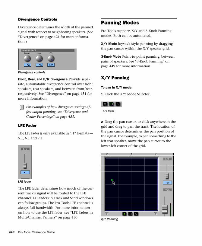
448
Divergence Controls
Divergence determines the width of the panned signal with respect to neighboring speakers. (See “Divergence” on page 421 for more informa-tion.)
Front, Rear, and F/R Divergence Provide sepa-rate, automatable divergence control over front speakers, rear speakers, and between front/rear, respectively. See “Divergence” on page 451 for more information.
LFE Fader
The LFE fader is only available in “.1” formats — 5.1, 6.1 and 7.1.
The LFE fader determines how much of the cur-rent track’s signal will be routed to the LFE channel. LFE faders in Track and Send windows can follow groups. The Pro Tools LFE channel is always full-bandwidth. For more information on how to use the LFE fader, see “LFE Faders in Multi-Channel Panners” on page 450
Divergence controls
For examples of how divergence settings af-fect output panning, see “Divergence and Center Percentage” on page 451.
LFE fader
Pro Tools Reference Guide
Panning ModesPro Tools supports X/Y and 3-Knob Panning modes. Both can be automated.
X/Y Mode Joystick-style panning by dragging the pan cursor within the X/Y speaker grid.
3-Knob Mode Point-to-point panning, between pairs of speakers. See “3-Knob Panning” on page 449 for more information.
X/Y Panning
To pan in X/Y mode:
1 Click the X/Y Mode Selector.
2 Drag the pan cursor, or click anywhere in the grid and drag to pan the track. The location of the pan cursor determines the pan position of the signal. For example, to pan something to the left rear speaker, move the pan cursor to the lower-left corner of the grid.
X/Y Panning
X/Y Mode
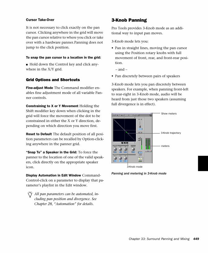
Cursor Take-Over
It is not necessary to click exactly on the pan cursor. Clicking anywhere in the grid will move the pan cursor relative to where you click or take over with a hardware panner.Panning does not jump to the click position.
To snap the pan cursor to a location in the grid:
■ Hold down the Control key and click any-where in the X/Y grid.
Grid Options and Shortcuts
Fine-adjust Mode The Command modifier en-ables fine adjustment mode of all variable Pan-ner controls.
Constraining to X or Y Movement Holding the Shift modifier key down when clicking in the grid will force the movement of the dot to be constrained in either the X or Y direction, de-pending on which direction you move first.
Reset to Default The default position of all posi-tion parameters can be recalled by Option-click-ing anywhere in the panner grid.
“Snap To” a Speaker in the Grid: To force the panner to the location of one of the valid speak-ers, click directly on the appropriate speaker icon.
Display Automation in Edit Window Command-Control-click on a parameter to display that pa-rameter’s playlist in the Edit window.
All pan parameters can be automated, in-cluding pan position and divergence. See Chapter 28, “Automation” for details.
3-Knob Panning
Pro Tools provides 3-Knob mode as an addi-tional way to input pan moves.
3-Knob mode lets you:
• Pan in straight lines, moving the pan cursor using the Position rotary knobs with full movement of front, rear, and front-rear posi-tion.
– and –
• Pan discretely between pairs of speakers
3-Knob mode lets you pan discretely between speakers. For example, when panning front-left to rear-right in 3-Knob mode, audio will be heard from just those two speakers (assuming full divergence is in effect).
Panning and metering in 3-Knob mode
3-Knob trajectory
3-Knob mode
meters
Show meters
Chapter 33: Surroun
d Panning and Mixing 449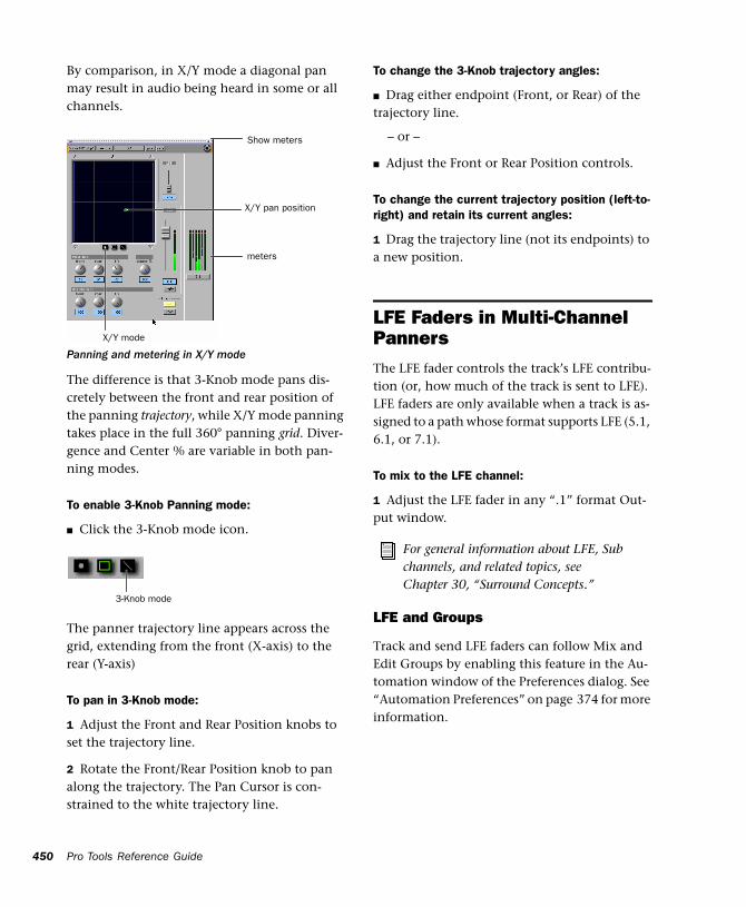
450
By comparison, in X/Y mode a diagonal pan may result in audio being heard in some or all channels.
The difference is that 3-Knob mode pans dis-cretely between the front and rear position of the panning trajectory, while X/Y mode panning takes place in the full 360° panning grid. Diver-gence and Center % are variable in both pan-ning modes.
To enable 3-Knob Panning mode:
■ Click the 3-Knob mode icon.
The panner trajectory line appears across the grid, extending from the front (X-axis) to the rear (Y-axis)
To pan in 3-Knob mode:
1 Adjust the Front and Rear Position knobs to set the trajectory line.
2 Rotate the Front/Rear Position knob to pan along the trajectory. The Pan Cursor is con-strained to the white trajectory line.
Panning and metering in X/Y mode
X/Y pan position
meters
Show meters
X/Y mode
3-Knob mode
Pro Tools Reference Guide
To change the 3-Knob trajectory angles:
■ Drag either endpoint (Front, or Rear) of the trajectory line.
– or –
■ Adjust the Front or Rear Position controls.
To change the current trajectory position (left-to-right) and retain its current angles:
1 Drag the trajectory line (not its endpoints) to a new position.
LFE Faders in Multi-Channel PannersThe LFE fader controls the track’s LFE contribu-tion (or, how much of the track is sent to LFE). LFE faders are only available when a track is as-signed to a path whose format supports LFE (5.1, 6.1, or 7.1).
To mix to the LFE channel:
1 Adjust the LFE fader in any “.1” format Out-put window.
LFE and Groups
Track and send LFE faders can follow Mix and Edit Groups by enabling this feature in the Au-tomation window of the Preferences dialog. See “Automation Preferences” on page 374 for more information.
For general information about LFE, Sub channels, and related topics, see Chapter 30, “Surround Concepts.”
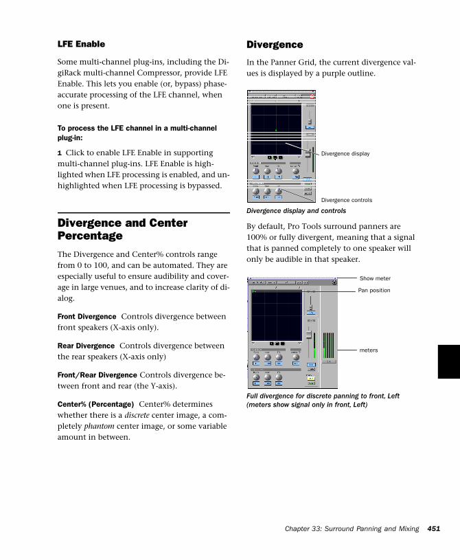
LFE Enable
Some multi-channel plug-ins, including the Di-giRack multi-channel Compressor, provide LFE Enable. This lets you enable (or, bypass) phase-accurate processing of the LFE channel, when one is present.
To process the LFE channel in a multi-channel plug-in:
1 Click to enable LFE Enable in supporting multi-channel plug-ins. LFE Enable is high-lighted when LFE processing is enabled, and un-highlighted when LFE processing is bypassed.
Divergence and Center PercentageThe Divergence and Center% controls range from 0 to 100, and can be automated. They are especially useful to ensure audibility and cover-age in large venues, and to increase clarity of di-alog.
Front Divergence Controls divergence between front speakers (X-axis only).
Rear Divergence Controls divergence between the rear speakers (X-axis only)
Front/Rear Divergence Controls divergence be-tween front and rear (the Y-axis).
Center% (Percentage) Center% determines whether there is a discrete center image, a com-pletely phantom center image, or some variable amount in between.
Divergence
In the Panner Grid, the current divergence val-ues is displayed by a purple outline.
By default, Pro Tools surround panners are 100% or fully divergent, meaning that a signal that is panned completely to one speaker will only be audible in that speaker.
Divergence display and controls
Full divergence for discrete panning to front, Left (meters show signal only in front, Left)
Divergence display
Divergence controls
Pan position
meters
Show meter
Chapter 3
3: Surroun d Panning and Mixing 451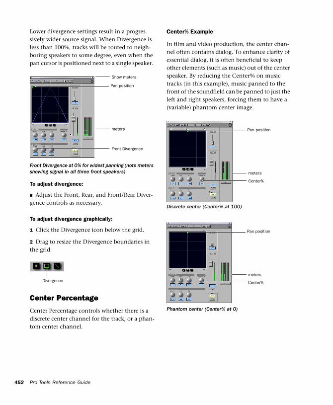
452
Lower divergence settings result in a progres-sively wider source signal. When Divergence is less than 100%, tracks will be routed to neigh-boring speakers to some degree, even when the pan cursor is positioned next to a single speaker.
To adjust divergence:
■ Adjust the Front, Rear, and Front/Rear Diver-gence controls as necessary.
To adjust divergence graphically:
1 Click the Divergence icon below the grid.
2 Drag to resize the Divergence boundaries in the grid.
Center Percentage
Center Percentage controls whether there is a discrete center channel for the track, or a phan-tom center channel.
Front Divergence at 0% for widest panning (note meters showing signal in all three front speakers)
Pan position
meters
Show meters
Front Divergence
Divergence
Pro Tools Reference Guide
Center% Example
In film and video production, the center chan-nel often contains dialog. To enhance clarity of essential dialog, it is often beneficial to keep other elements (such as music) out of the center speaker. By reducing the Center% on music tracks (in this example), music panned to the front of the soundfield can be panned to just the left and right speakers, forcing them to have a (variable) phantom center image.
Discrete center (Center% at 100)
Phantom center (Center% at 0)
Pan position
meters
Center%
Pan position
meters
Center%

To adjust Center Percentage:
■ Adjust the Center% knob as appropriate.
As you reduce the Center% value, the center speaker icon at the top of the grid becomes less visible. At 0, the center speaker icon is com-pletely invisible, reflecting the setting for fully phantom center.
Pan Playlists and Automation
Multi-channel panners have several automation playlists associated with them (for each position and divergence control it provides).
Panning Does Not Follow Groups
Unlike mute and volume breakpoint editing, pan automation by default does not follow edit groups. To force pan automation editing to fol-low groups, you can hold down the Control key while editing automation breakpoints on a member track. This feature applies to all seven types of pan controls (front, rear, and front/rear pan position, front divergence, rear divergence, front/rear divergence, and center percentage).
SurroundScope Metering Plug-InThe SurroundScope Metering plug-in provides a 360° meter for multi-channel mixing. It pro-vides a method of metering multi-channel paths, and is available in all multi-channel for-mats.
5.1 Format Track Layouts
All on-screen, 5.1-format meters (including those displayed in the SurroundScope meter, on tracks, and in Output windows and their Meter views) are always arranged:
L C R Ls Rs LFE
To use the SurroundScope Metering Plug-In:
■ On a multi-channel Master Fader, click an In-sert button and select the multi-channel Meter plug-in.
SurroundScope has no adjustable parameters, but displays output levels in both a 360° grid, and in traditional LED meters.
For a complete explanation of Pro Tools metering, see “5.1 Tracks, Formats, Map-ping and Metering” on page 429.
Chapter 33: Surround Panning and Mixing 453

454
Pro Tools Reference Guide
Part VIII: Synchronization
455

456
Chapter 34: Synchronization Concepts
Time code and synchronization (sync) are com-plex topics. This section is designed to give you a basic understanding of synchronization as it relates to Pro Tools.
However, if you are using a device that sends or receives time code, such as a video tape recorder (VTR), you need to understand how that device generates or receives time code, and how to con-figure its options. Refer to your video device documentation for more information.
Your Sync RequirementsIt is strongly recommended that you research what your synchronization requirements are. For example, if you are using Pro Tools to ac-complish audio post-production work for video, consult with the video engineer or editor to de-termine what time code format is being used. There may be other time code issues that affect how you use synchronization. Your Digidesign dealer may also be able to offer suggestions about working with sync with your studio.
Aspects of SyncSynchronization has two components, which can be expressed as the following questions:
◆ “Where are we?” This is called the positional reference.
◆ “How fast are we going?” This is called the clock reference.
To synchronize Pro Tools accurately over an ex-tended period of time to another device such as a tape machine or VTR, Pro Tools needs to know where the device is and at what speed it’s run-ning. Some peripherals can provide only one of these references; for example, a black burst gen-erator provides only a clock reference. Some pe-ripherals, like the Digidesign Universal Slave Driver (USD), can provide both.
Syncing Pro ToolsPro Tools requires a clock reference, in addition to time code, to maintain synchronization over time.
You can resolve Pro Tools to an external clock reference without locking it to a positional ref-erence. For example, you can use a USD to re-solve the Pro Tools sample clock to house sync,
Chapter 34: Synchronization Concepts 457
458
without synchronizing Pro Tools to external time code. You should do this if you need all your work in Pro Tools to match the speed of all other machines in your facility.
This can be explored further by using a typical sync situation, with Pro Tools being slaved, us-ing a Universal Slave Driver (USD), to a video tape recorder, with both machines referenced to the same house sync or black burst source:
1 When you start the videotape, time code (LTC or VITC) is read off the tape and routed to the USD.
2 The USD sends Pro Tools the address of the first instance of time code it receives (positional reference). At the same time, based on the house sync or black burst clock reference, the USD sends Super Clock information to Pro Tools (clock reference).
3 Pro Tools takes the first time code address it re-ceives, and calculates the sample location in the session that corresponds to the address. Though you can work with Pro Tools using any standard time code format, it calculates internally in sam-ple numbers. This means that Pro Tools trans-lates a time code frame address to an exact sample number.
4 Assuming that the time code address corre-sponds to a sample number that is within the Pro Tools session, Pro Tools converts the time code address to a sample number within the ses-sion, and begins playing from that point. The point that playback starts from is the trigger point. The clock reference is used by both ma-chines to keep them in sync.
5 At this point, if the videotape is stopped, re-wound, and started again, the entire process is repeated, based upon a newly calculated trigger point.
Pro Tools Reference Guide
In this way, Pro Tools uses time code for posi-tional information, and a clock reference to maintain synchronization.
About Positional References
Time code is timing information in the form of a data stream that can be recorded on magnetic tape as an audio or video signal. Time code can be used to synchronize the playback and record-ing of your Pro Tools system with another ma-chine’s transport, such as an analog multitrack tape machine or a video tape recorder (VTR).
SMPTE and ISO/EBU Time Code
The “Where are we?” question refers to relative position. To describe position, many profes-sional audio, video, and multimedia devices and programs use SMPTE (Society of Motion Picture & Television Engineers) time code. In Europe, a standard called ISO (International Standards Or-ganization) time code, formerly called EBU (Eu-ropean Broadcasters Union) time code, is gener-ally used. These time code types are almost exactly the same in terms of how they are repre-sented electronically. However, ISO/EBU time code works at a fixed rate of 25 fps (frames per second) and SMPTE includes provisions for sev-eral different frame rates. For the purposes of ex-planation, this chapter will generally refer to frame-measured timing information as “SMPTE time code.” This description should be under-stood to include ISO/EBU and SMPTE time code.
SMPTE Time Code Methods
There are two basic techniques used to record SMPTE time code onto magnetic tape: LTC (Lin-ear Time Code) and VITC (Vertical Interval Time Code). LTC is recorded on an audio channel or a dedicated time code track of the audio or video device. VITC is recorded within the video signal in the video “blanking area” of each video
frame. VITC cannot be recorded on audio tracks, so it has no application when working with au-dio tape recorders, but it does offer powerful fea-tures for post-production professionals who work with video.
There is also a non-SMPTE form of time code called MIDI Time Code (MTC) that some devices use to send timing information.
SMPTE Time Code Units
Time code describes locations in terms of hours, minutes, seconds, frames, and subframes (1/100th of a frame). The frame is used as a unit of time measurement due to SMPTE time code’s origin in film and video applications. Depend-ing on the SMPTE frame rate, one frame is equal to 1/24th, 1/25th, 1/29.97th, or 1/30th of a sec-ond. For example, a videotape time code read-ing of “01:12:27:15” would tell us that we were at a position of one hour, twelve minutes, twenty-seven seconds, and fifteen frames. How-ever, this time address alone does not tell us frame rate information.
Because SMPTE stores an absolute time reference on the tape in the form of time code, any loca-tion on that tape can be precisely located by de-vices that read time code. Once the time code has been recorded or striped on a tape, it pro-vides a permanent time reference that allows Pro Tools to link the playback of an event to an exact tape location. For example, with time code sync, a gun shot sound effect can be played at the precise instant that the gun’s flash appears on-screen.
LTC (Linear Time Code)
LTC is time code that is recorded and played back, or generated, in the form of an analog au-dio signal. LTC is supported by many audio and video tape recorders.
LTC Speed Usage
LTC can be read at high tape shuttle speeds, al-lowing a machine’s time code reader to commu-nicate with synchronizers at rewind or fast for-ward speeds exceeding 50 times playback speed (provided the tape recorder is able to reproduce the time code at this speed). However, LTC can-not be read at very slow shuttle speeds (such as when you are “crawling” the tape frame by frame) or when the machine is paused. With LTC, the VTR must be running (usually at a min-imum speed of about 1/10th normal playback speed) in order to capture a SMPTE time address.
VITC (Vertical Interval Time Code)
VITC is a type of time code that is recorded and played as an invisible part of a video signal. VITC is commonly used in professional video editing and audio-for-picture applications. Be-cause VITC is recorded as part of each video frame, it must be recorded at the same time as the video signal—it cannot be added later as LTC can. Since VITC cannot be recorded on au-dio tracks, it is never used to synchronize audio-only recorders. Instead, LTC is most often used in audio-only applications.
VITC Speed Usage
VITC’s ability to be read when moving a VTR transport at slow speeds or when the VTR is paused makes it more useful in audio post-pro-duction environments than LTC.
When VITC is used, Pro Tools can capture the current SMPTE time from the VTR when it is paused or in “crawl” mode. However, if you are using additional external transport synchroniz-ers in your setup, most synchronizers cannot
Chapter 34: Synchronization Concepts 459
460
read VITC at speeds exceeding approximately 10 times playback speed, preventing slaved ma-chines from maintaining synchronization dur-ing rewind and fast forward.
LTC/VITC Auto-Switching
Many synchronizers and devices support auto-matic switching between LTC and VITC, de-pending on the speed, to get the best of both worlds. For example, VITC might be used when a VTR is paused, or crawling frame-by frame, while the synchronizer might automatically switch to LTC when fast-forwarding.
Bi-Phase/Tach
This electronic pulse stream is used by film mag recorders, film editing stations, and film projec-tors. You can use this format to synchronize Pro Tools if you have a USD. Unlike time code, bi-phase/tach doesn’t actually contain absolute location information. It simply supplies speed (based upon the frequency of the pulses) and di-rection, and therefore, relative position. Since the USD can “count” both the speed and direc-tion of the stream of pulses, it can use a bi-phase/tach source to deduce positional informa-tion from a starting “address point.” The differ-ence between bi-phase and tach formats is that bi-phase encodes rate and direction on a pair of signals using a format called phase-quadrature, while tach encodes rate on one signal and direc-tion on the other.
Pro Tools Reference Guide
SMPTE Frame FormatsSix different formats of SMPTE time code exist, and Pro Tools can sync to any format with a compatible sync peripheral. The supported SMPTE frame rates are:
• 30 fps (frames per second), also called 30 Non-Drop
• 30 fps Drop frame
• 29.97 fps, also called 29.97 Non-Drop
• 29.97 fps Drop frame
• 25 fps (also called ISO or EBU)
• 24 fps
30 fps Frame Format
This is the original SMPTE format developed for monochrome (black & white) video, and is com-monly used in audio-only applications. This for-mat is often referred to as 30 Non-Drop frame format.
30 fps Drop Frame Format
This format is used for sound recordings done for film-originated programs that are destined for NTSC broadcast.
29.97 Non-Drop Frame Format
This format is used with NTSC color video. It runs at a rate of 29.97 fps.
When you work with NTSC video (the stan-dard in North America), you will generally work with the NTSC color video standard: either 29.97 fps Non-Drop or 29.97 fps Drop frame.
29.97 Drop Frame Format
NTSC color video has an actual frame rate of 29.97 fps, so an hour’s worth of frames (108,000) running at 29.97 fps Non-Drop will take slightly longer than one hour of real time to play. This makes calculating the actual length of a program difficult when using 29.97 Non-Drop time code. A program that spans one hour of 29.97 Non-Drop time code addresses (e.g. from 1:00:00:00 to 2:00:00:00) is actually 60 minutes, 3 seconds and 18 frames long.
To make working with 29.97 time code easier for broadcasters, the SMPTE committee created 29.97 Drop Frame time code, which runs at ex-actly the same speed as 29.97 Non-Drop (non-drop frame) time code, but compensates for the slower speed by “dropping” (omitting) two frames at the top of each minute, with the ex-ception of every 10th minute. For this reason, the time code address of 1:01:00:00 does not ex-ist in drop frame code because it has been skipped.
At the end of a program that spans precisely one hour of drop frame time code (1:00:00;00 to 2:00:00;00 for example), exactly one hour of real time has elapsed.
Although it sounds complicated, drop frame time code allows broadcasters to rely on time code values when calculating the true length of programs, facilitating accurate program sched-uling.
Note that even though time code addresses are skipped in drop-frame format, actual frames of video material are not dropped.
25 fps Frame Format
This format is used with the European PAL video standard, which runs at a 25 fps frame rate. This format is also called the EBU (European Broad-cast Union) format because it’s used by broad-casters throughout most of Europe.
24 fps Frame Format
This format is used exclusively for film applica-tions. Film is typically photographed and pro-jected at a 24 fps frame rate, so this SMPTE for-mat is useful when one time code frame should equal one film frame.
Working with Film-Originated MaterialWhen you do post-production work in Pro Tools, you will usually work with video ma-terial. However, it is possible that the video you are working on was shot on film.
Film footage and production sound go through separate conversion processes before they reach video, and the audio post-production stage. The film is transferred to video using a process called Telecine, using a method called 3:2 Pulldown. Audio can also be pulled down during the trans-fer, or you might end up working with audio that has not been adjusted (production sound).
Typically during the Telecine process, a master digital video tape is created, along with a work copy on 3/4” analog video tape for the picture editor to use. At the same time, a new audio master may be created by slowing down, or “pulling down” by 0.1%, the production sound to compensate for the change in speed from film to NTSC video.
Chapter 34: Synchronization Concepts 461
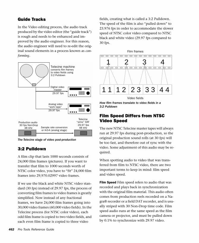
462
Guide Tracks
In the Video editing process, the audio track produced by the video editor (the “guide track”) is rough and needs to be enhanced and im-proved by the audio engineer. For this reason, the audio engineer will need to re-edit the orig-inal sound elements in a process known as con-forming.
3:2 Pulldown
A film clip that lasts 1000 seconds consists of 24,000 film frames (pictures). If you want to transfer that film to 1000 seconds worth of NTSC color video, you have to “fit” 24,000 film frames into 29,970.02997 video frames.
If we use the black and white NTSC video stan-dard (30 fps) instead of 29.97 fps, the process of converting film frames to video frames is greatly simplified. Now instead of any fractional frames, we have 24,000 film frames going into 30,000 video frames (60,000 video fields). In the Telecine process (for NTSC color video), each odd film frame is copied to two video fields, and each even film frame is copied to three video
The Telecine stage of video post-production
Telecine machineconverts film framesto video fields using
Digital video
3:2 Pulldown
Analog video“work tape”
master
Production audio30 fps Non-Drop
48 kHz
Telecine
29.97 fps48 kHzSample rate conversion
or A-D-A (analog stage)
29.97 fps
29.97 fps
“simo” DAT
Pro Tools Reference Guide
fields, creating what is called a 3:2 Pulldown. The speed of the film is also “pulled down” to 23.976 fps in order to accommodate the slower speed of NTSC color video compared to NTSC black and white video (29.97 fps compared to 30 fps.
Film Speed Differs from NTSC Video Speed
The new NTSC Telecine master tapes will always run at 29.97 fps during post-production, so the original production sound rolls (at 30 fps) will be too fast, and therefore out of sync with the video. Some adjustment of this audio may be re-quired.
When spotting audio to video that was trans-ferred from film to NTSC video, there are two important terms to keep in mind: film speed and video speed.
Film Speed Film speed refers to audio that was recorded and plays back in synchronization with the original film material. This audio often comes from production reels recorded on a Na-gra® recorder or a field DAT recorder, and is usu-ally striped with 30 Non-Drop time code. Film speed audio runs at the same speed as the film camera or projector, and must be pulled down by 0.1% to synchronize with 29.97 video.
How film frames translate to video fields in a 3:2 Pulldown
1 1 1 2 2 3 3 3 4 4
1 2 3 4
Film frames
Video fields
Video Speed
Video speed refers to audio that is running at the NTSC color standard of 29.97 fps. Video speed is 0.1% slower than film speed, so audio that is still at film speed will be out of sync with the video. Usually, you will be working at video speed, though Digidesign and Avid do provide several options for film speed (24 fps) support.
Pull Up and Pull Down
Pull Up
and
Pull Down
are terms used to refer to the deliberate recalibration of the audio sample rate clock (speed, or musical pitch) in order to compensate for a speed change. Pro Tools can be used to pull down or pull up audio for use with NTSC video. Pro Tools does not support Pull Up or Pull Down sample rates for converting be-tween PAL and NTSC video.
Pull Down allows you is to play back film origi-nated material at video speed (-0.1%). Pull Up allows you to play back video speed material at film speed (+0.1%).
Using Pro Tools in Pull Up or Pull Down modes requires a USD, SSD, or a third-party synchro-nizer that supports 256x clock output and Pull Up and Pull Down sample rates. The VSD can be used for Pull Down, but does not support Pull Up mode.
When to Pull Up or Pull Down
There are many ways to get audio into Pro Tools for post-production. Consider your source audio and your final destination format carefully. In some cases, audio will already be pulled down for you. In other cases, audio will have to be temporarily pulled down. In still other cases, you may choose to pull down your audio source, like a DAT deck, then use a D-A-D (digi-tal-to-analog-to-digital) conversion to record the audio into Pro Tools at the proper sample
rate. Or you may choose only to pull Pro Tools up or down on delivery of the audio. Refer to the online document FilmSync.pdf installed with your Pro Tools documentation, for detailed Pull Up/Down workflow information.
Final Audio Destination: Film
If your final destination is film, your source au-dio is at film speed, and your goal is to edit and mix audio in Pro Tools and then lay back to a device that runs at film speed (such as mag or time code DAT), you can temporarily pull down the audio in Pro Tools for NTSC video work, then return the audio back to film speed when you’re finished.
For example, film speed audio from a Nagra ma-chine that is referenced to 30 fps time code is re-corded into your Pro Tools system at a sample rate of 44.1 or 48 kHz. Keeping in mind that film speed is faster than video speed, select 30 fps in your Session Setup window in Pro Tools, and record in your audio online and referenced to the time code on the Nagra.
Once all the audio has been recorded, and you are locked to a video work print (at video speed), enable Pull Down. If you are using a Digidesign USD, SSD, or VSD, select Pull Down in the Ses-sion Setup window. (You also have to select Pull Down manually on the front of the VSD.) If your synchronizer is not a Digidesign product, select Pull Down on the front of your synchro-nizer, then enable Pull Down in the Pro Tools Session Setup window. At this point, it is highly recommended that you verify whether the video you’re working with is striped with 29.97 Drop Frame or Non-Drop Frame time code. While in Pull Down mode, you can work with your reference video and everything will remain in sync and run at the proper speed (assuming your system is completely resolved).
Chapter 34: Synchronization Concepts 463
464
Once you are ready to lay back your completed project to an audio device running at film speed, deselect Pull Down in the Session Setup win-dow, and from your synchronizer if it is not a USD or SSD. Then change your time code frame rate in the Pro Tools session back to 30 fps. Once Pull Down has been deselected, the audio played back from Pro Tools will synchronize perfectly with the edited film.
Alternatively, you can pull down the source au-dio deck while recording audio into Pro Tools, work at 29.97 fps with no Pull-Down selected in Pro Tools, and then switch to 30 Non-Drop frame format, and select Pull Up during the de-livery stage. You will have to perform a sample rate conversion on the audio either digitally or by using an analog stage (D-A-D).
Final Audio Destination: Video
If you are working with video that was trans-ferred from film, your audio source is at film speed, and the final layback destination is NTSC video (or television), and you would like to pro-vide a digital transfer to your clients, you will need to alter the above recipe slightly. Keep in mind that when you are working in Pull Down mode, your active sample rate is 44.056 kHz (if the audio was recorded at 44.1 kHz) or 47.952 kHz (if the audio was recorded at 48 kHz).
Pull Down the Audio Source
Some professional DAT machines will let you pull down the sample rate to 44.056 kHz (and 47.952 kHz). You can record this audio into Pro Tools using a D-A-D (digital-to-analog-to-digital) process. Then your audio will be at the correct speed for the remainder of the project, since the final destination is video, and no Pull Down or Pull Up is necessary.
Pro Tools Reference Guide
Pull Up Pro Tools While Recording
If you cannot pull down your source, you can accomplish the same thing by Pulling Up Pro Tools, and setting your SMPTE frame format to 30 fps, before recording in the production sound. First select 30 fps as the frame format in the Session Setup window. Then select Pull Up in the Session Setup window (and on your syn-chronizer if it isn’t a USD or SSD) before you record in the production audio. In this case, while the production audio is running at 44.1 or 48 kHz, Pro Tools is running (and recording) at a rate of 44.144 or 48.048 kHz. After all the pro-duction audio has been recorded into Pro Tools, deselect Pull Up in the Session Setup window and on your hardware synchronizer if it is not a USD or SSD. After you deselect Pull Up, the re-corded audio will play back 0.1% slower, syn-chronized with the video, while achieving a true playback sample rate of 44.1 or 48 kHz. Note that this process is designed for a final destina-tion of video; to bring this audio back up to film speed you would have to pull up Pro Tools and record to a destination that is not Pulled Up.
Note on Sample Rate Conversion
In many cases, you have to perform a sample rate conversion at some point, either digitally, or by recording in audio using an analog stage (D-A-D). The only situation where sample rate conversion never has to be performed is when you are working with film speed audio and your final destination format is film. Then you can simply pull down Pro Tools while you work with the video, then deselect Pull Down to set the au-dio back to film speed.
Using Digital Input
Do not set Pro Tools channels 1 and 2 to Digital Input while working with Pull Up or Pull Down. This will override the USD’s clock reference set-ting.
Chapter 34: Synchronization Concepts 465

466
Pro Tools Reference Guide
Chapter 35: Time Code Synchronization
Synchronization (sync) allows connected sys-tems or devices to start and stop their transports together, and, in some cases, to adjust transport speeds to maintain accurate synchronization of audio and video material during playback. Pro Tools is synchronized to other devices using SMPTE time code or MIDI Time Code. For a dis-cussion of different SMPTE formats, and other concepts related to time code, refer to Chapter 34, “Synchronization Concepts.”
Pro Tools Sync Options
You have four choices for synchronizing Pro Tools to an external source:
SMPTE Trigger Only
This solution is useful for short projects, but may result in timing errors if you are working with lengthy program material and an unstable sync source. This is the only option available on Pro Tools LE systems.
SMPTE Trigger with an Externally Resolved Peripheral
(TDM Systems Only)
This solution uses a Universal Slave Driver (USD), Video Slave Driver (VSD), or equivalent third-party device, resolved with a black burst or “house sync” generator, or using external word clock, to control playback and recording speed in Pro Tools. Accurate long-term sync can be achieved when all transports within the system are resolved to a common sync source.
SMPTE Trigger with an External Peripheral Slaved to LTC
SMPTE Trigger can be used with the optional USD, SMPTE Slave Driver (SSD), or equivalent third-party device to resolve Pro Tools record-ing/playback speed while slaving to LTC. This enables longterm, accurate synchronization by resolving to any variations in incoming time code.
Chapter 35: Time Code Synchronization 467
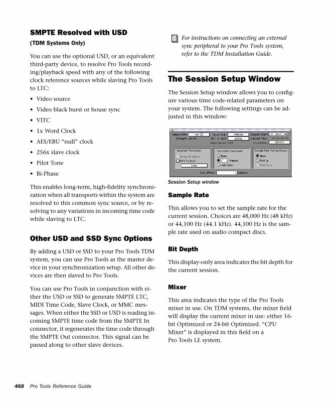
468
SMPTE Resolved with USD(TDM Systems Only)
You can use the optional USD, or an equivalent third-party device, to resolve Pro Tools record-ing/playback speed with any of the following clock reference sources while slaving Pro Tools to LTC:
• Video source
• Video black burst or house sync
• VITC
• 1x Word Clock
• AES/EBU “null” clock
• 256x slave clock
• Pilot Tone
• Bi-Phase
This enables long-term, high-fidelity synchroni-zation when all transports within the system are resolved to this common sync source, or by re-solving to any variations in incoming time code while slaving to LTC.
Other USD and SSD Sync Options
By adding a USD or SSD to your Pro Tools TDM system, you can use Pro Tools as the master de-vice in your synchronization setup. All other de-vices are then slaved to Pro Tools.
You can use Pro Tools in conjunction with ei-ther the USD or SSD to generate SMPTE LTC, MIDI Time Code, Slave Clock, or MMC mes-sages. When either the SSD or USD is reading in-coming SMPTE time code from the SMPTE In connector, it regenerates the time code through the SMPTE Out connector. This signal can be passed along to other slave devices.
Pro Tools Reference Guide
The Session Setup Window
The Session Setup window allows you to config-ure various time code-related parameters on your system. The following settings can be ad-justed in this window:
Sample Rate
This allows you to set the sample rate for the current session. Choices are 48,000 Hz (48 kHz) or 44,100 Hz (44.1 kHz). 44,100 Hz is the sam-ple rate used on audio compact discs.
Bit Depth
This display-only area indicates the bit depth for the current session.
Mixer
This area indicates the type of the Pro Tools mixer in use. On TDM systems, the mixer field will display the current mixer in use: either 16-bit Optimized or 24-bit Optimized. “CPU Mixer” is displayed in this field on a Pro Tools LE system.
For instructions on connecting an external sync peripheral to your Pro Tools system, refer to the TDM Installation Guide.
Session Setup window
Sync Mode
This allows you to choose the clock mode for your master Audio Interface, Audiomedia III card, or Digi 001. Choices are Internal or Digital on an Audio Interface or Audiomedia III card, and Internal, Optical, or S/PDIF (RCA) on the Digi 001.
Internal Sync Mode In internal sync mode, your system will reference your Digidesign card or pe-ripheral’s quartz crystal oscillator and play back at the sample rate selected in the Sample Rate field.
Digital Sync Mode (including Optical and S/PDIF on Digi 001) In digital sync mode, your system’s sample rate is adjusted to match the sample rate received from the selected digital peripheral. In digital sync mode, your Pro Tools sync rate must match the rate received by your digital periph-eral. Incorrectly set peripheral devices will result in incorrect playback speeds when your system is set back to internal sync mode.
With TDM systems, the Session Setup window provides a source link feature that toggles the sync mode of your audio interface when you switch your input source from analog to digital. This helps to ensure that the clock source for your system will match the digital input source when you are working.
You can override this toggled behavior by changing the pop-ups to the opposite choice. For example, if you are using a master AES/EBU null clock or video black burst signal source as the master sync source for all digital audio de-vices in your studio setup, your Sync Mode pop-up should be set to digital at all times. In this case, Pro Tools uses this master sync source as a reference.
Ch 1-2 Input (TDM Systems Only)
This allows you to choose an audio input format (analog or digital) for channels 1 and 2 of your master Audio Interface.
Audio Format
This display-only area indicates the file format for files recorded in the session.
Session Start
This allows you to specify a SMPTE start frame location for your session. The SMPTE value that you enter here will be used to trigger playback and record when Pro Tools is online. See “Set-ting a SMPTE Start Frame” on page 472.
Current Time
This displays incoming time code.
Frame Rate
This allows you to set the SMPTE frame rate for the current session.
Generate Time Code
This allows Pro Tools to output time code using a USD (communicating directly via a serial port), or using a SSD (communicating via a serial port or using MIDI sysex via a designated OMS destination port). Generating time code is cov-ered in the section “Generating Time Code” on page 474.
Using Peripheral
This option outputs time code from the Device type selected in the Synchroni-zation page of the Peripherals dialog.
MTC to Port
This option outputs MIDI Time Code to the MIDI destination selected in the pop-up menu.
Chapter 35: Time Code Synchronization 469
470
Time Code Freewheel
This allows Pro Tools to continue playback if time code is interrupted or corrupted. Use this to protect against errors that can occur if your SMPTE time code source has “drop outs” or tem-porary lost signals.
Frames This option allows you to freewheel from 1 to 120 frames. This value defaults to 8 frames, which is the recommended setting for most applications.
Jam Sync This option allows Pro Tools to trigger sync to incoming time code, and continue to play back even if time code input is completely interrupted. It can be useful if time code is dam-aged, or has been accidentally erased from your source tape.
Sample Rate Pull Up/Down
When Pro Tools is used in conjunction with a SSD, VSD, USD, or third-party synchronizer that supports 256x clock output and Pull Down sam-ple rates, this option allows you to “pull up” or “pull down” the current sample rate. This is used with film-originated material when work-ing with NTSC-standard SMPTE frame rates only. For a full explanation of film-originated scenarios, see “Working with Film-Originated Material” on page 461.
Pull Up This speeds up the current sample rate to 100.1%. A 48 kHz sample rate is sped up to 48.048 kHz. A 44.1 kHz sample rate is sped up to 44.144 kHz.
Pull Down This slows the current sample rate to 99.9%. A 48 kHz sample rate is slowed to 47.952 kHz. A 44.1 kHz sample rate is slowed to 44.056 kHz.
Pro Tools Reference Guide
Sync Offset
This field allows you to set a “trigger offset” for incoming MIDI Time Code (anywhere from –100000 to +100000 samples). This allows you to create a permanent offset to fine-tune the point at which Pro Tools syncs relative to in-coming time code. For example, a value of -50 makes an event in Pro Tools occur 50 samples before the same event in the incoming MIDI Time Code. Use this to compensate for timing differences between various SMPTE-to-MIDI Time Code converters or analog-to-digital/digi-tal-to-analog converters.
Sync Offset Voice Usage
For TDM systems, recording with a Sync Offset requires two voices for each record-enabled track. In addition, to simultaneously record on 32 tracks with a Sync Offset on a Pro Tools 24 MIX system (which allocates voices to either of two DSP engines, 1–32 and 33–64), the tracks must be evenly distributed between the two DSPs, (for instance, tracks 1–16 assigned to voices 1–16 and tracks 17–32 assigned to voices 33–48).
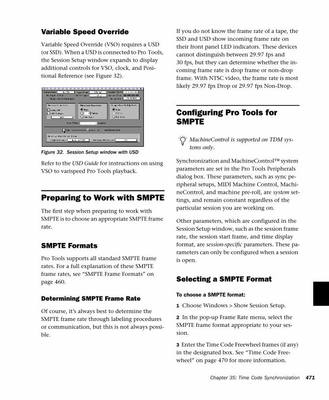
Variable Speed Override
Variable Speed Override (VSO) requires a USD (or SSD). When a USD is connected to Pro Tools, the Session Setup window expands to display additional controls for VSO, clock, and Posi-tional Reference (see Figure 32).
Refer to the USD Guide for instructions on using VSO to varispeed Pro Tools playback.
Preparing to Work with SMPTEThe first step when preparing to work with SMPTE is to choose an appropriate SMPTE frame rate.
SMPTE Formats
Pro Tools supports all standard SMPTE frame rates. For a full explanation of these SMPTE frame rates, see “SMPTE Frame Formats” on page 460.
Determining SMPTE Frame Rate
Of course, it’s always best to determine the SMPTE frame rate through labeling procedures or communication, but this is not always possi-ble.
Figure 32. Session Setup window with USD
If you do not know the frame rate of a tape, the SSD and USD show incoming frame rate on their front panel LED indicators. These devices cannot distinguish between 29.97 fps and 30 fps, but they can determine whether the in-coming frame rate is drop frame or non-drop frame. With NTSC video, the frame rate is most likely 29.97 fps Drop or 29.97 fps Non-Drop.
Configuring Pro Tools for SMPTE
Synchronization and MachineControl™ system parameters are set in the Pro Tools Peripherals dialog box. These parameters, such as sync pe-ripheral setups, MIDI Machine Control, Machi-neControl, and machine pre-roll, are system set-tings, and remain constant regardless of the particular session you are working on.
Other parameters, which are configured in the Session Setup window, such as the session frame rate, the session start frame, and time display format, are session-specific parameters. These pa-rameters can only be configured when a session is open.
Selecting a SMPTE Format
To choose a SMPTE format:
1 Choose Windows > Show Session Setup.
2 In the pop-up Frame Rate menu, select the SMPTE frame format appropriate to your ses-sion.
3 Enter the Time Code Freewheel frames (if any) in the designated box. See “Time Code Free-wheel” on page 470 for more information.
MachineControl is supported on TDM sys-tems only.
Chapter 35: Time Code Synchronization 471
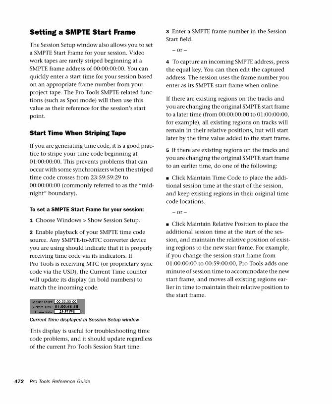
472
Setting a SMPTE Start Frame
The Session Setup window also allows you to set a SMPTE Start Frame for your session. Video work tapes are rarely striped beginning at a SMPTE frame address of 00:00:00:00. You can quickly enter a start time for your session based on an appropriate frame number from your project tape. The Pro Tools SMPTE-related func-tions (such as Spot mode) will then use this value as their reference for the session’s start point.
Start Time When Striping Tape
If you are generating time code, it is a good prac-tice to stripe your time code beginning at 01:00:00:00. This prevents problems that can occur with some synchronizers when the striped time code crosses from 23:59:59:29 to 00:00:00:00 (commonly referred to as the “mid-night” boundary).
To set a SMPTE Start Frame for your session:
1 Choose Windows > Show Session Setup.
2 Enable playback of your SMPTE time code source. Any SMPTE-to-MTC converter device you are using should indicate that it is properly receiving time code via its indicators. If Pro Tools is receiving MTC (or proprietary sync code via the USD), the Current Time counter will update its display (in bold numbers) to match the incoming code.
This display is useful for troubleshooting time code problems, and it should update regardless of the current Pro Tools Session Start time.
Current Time displayed in Session Setup window
Pro Tools Reference Guide
3 Enter a SMPTE frame number in the Session Start field.
– or –
4 To capture an incoming SMPTE address, press the equal key. You can then edit the captured address. The session uses the frame number you enter as its SMPTE start frame when online.
If there are existing regions on the tracks and you are changing the original SMPTE start frame to a later time (from 00:00:00:00 to 01:00:00:00, for example), all existing regions on tracks will remain in their relative positions, but will start later by the time value added to the start frame.
5 If there are existing regions on the tracks and you are changing the original SMPTE start frame to an earlier time, do one of the following:
■ Click Maintain Time Code to place the addi-tional session time at the start of the session, and keep existing regions in their original time code locations.
– or –
■ Click Maintain Relative Position to place the additional session time at the start of the ses-sion, and maintain the relative position of exist-ing regions to the new start frame. For example, if you change the session start frame from 01:00:00:00 to 00:59:00:00, Pro Tools adds one minute of session time to accommodate the new start frame, and moves all existing regions ear-lier in time to maintain their relative position to the start frame.
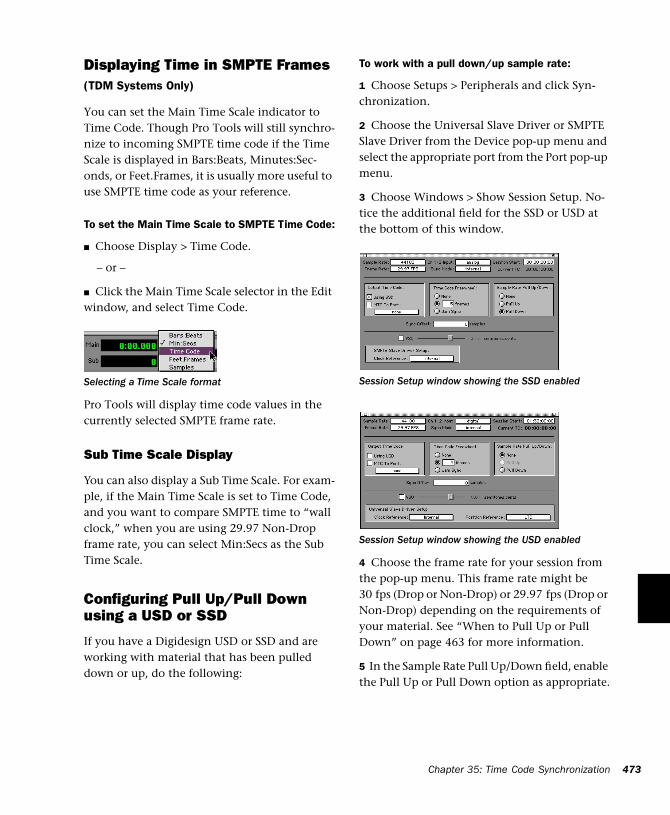
Displaying Time in SMPTE Frames(TDM Systems Only)
You can set the Main Time Scale indicator to Time Code. Though Pro Tools will still synchro-nize to incoming SMPTE time code if the Time Scale is displayed in Bars:Beats, Minutes:Sec-onds, or Feet.Frames, it is usually more useful to use SMPTE time code as your reference.
To set the Main Time Scale to SMPTE Time Code:
■ Choose Display > Time Code.
– or –
■ Click the Main Time Scale selector in the Edit window, and select Time Code.
Pro Tools will display time code values in the currently selected SMPTE frame rate.
Sub Time Scale Display
You can also display a Sub Time Scale. For exam-ple, if the Main Time Scale is set to Time Code, and you want to compare SMPTE time to “wall clock,” when you are using 29.97 Non-Drop frame rate, you can select Min:Secs as the Sub Time Scale.
Configuring Pull Up/Pull Down using a USD or SSD
If you have a Digidesign USD or SSD and are working with material that has been pulled down or up, do the following:
Selecting a Time Scale format
To work with a pull down/up sample rate:
1 Choose Setups > Peripherals and click Syn-chronization.
2 Choose the Universal Slave Driver or SMPTE Slave Driver from the Device pop-up menu and select the appropriate port from the Port pop-up menu.
3 Choose Windows > Show Session Setup. No-tice the additional field for the SSD or USD at the bottom of this window.
4 Choose the frame rate for your session from the pop-up menu. This frame rate might be 30 fps (Drop or Non-Drop) or 29.97 fps (Drop or Non-Drop) depending on the requirements of your material. See “When to Pull Up or Pull Down” on page 463 for more information.
5 In the Sample Rate Pull Up/Down field, enable the Pull Up or Pull Down option as appropriate.
Session Setup window showing the SSD enabled
Session Setup window showing the USD enabled
Chapter 35: Time Code Synchronization 473
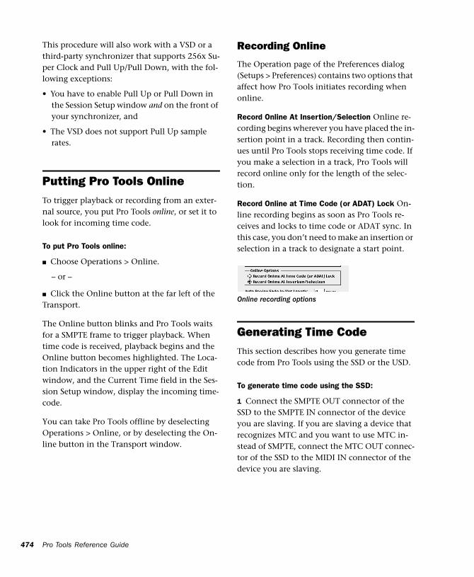
474
This procedure will also work with a VSD or a third-party synchronizer that supports 256x Su-per Clock and Pull Up/Pull Down, with the fol-lowing exceptions:
• You have to enable Pull Up or Pull Down in the Session Setup window and on the front of your synchronizer, and
• The VSD does not support Pull Up sample rates.
Putting Pro Tools OnlineTo trigger playback or recording from an exter-nal source, you put Pro Tools online, or set it to look for incoming time code.
To put Pro Tools online:
■ Choose Operations > Online.
– or –
■ Click the Online button at the far left of the Transport.
The Online button blinks and Pro Tools waits for a SMPTE frame to trigger playback. When time code is received, playback begins and the Online button becomes highlighted. The Loca-tion Indicators in the upper right of the Edit window, and the Current Time field in the Ses-sion Setup window, display the incoming time-code.
You can take Pro Tools offline by deselecting Operations > Online, or by deselecting the On-line button in the Transport window.
Pro Tools Reference Guide
Recording Online
The Operation page of the Preferences dialog (Setups > Preferences) contains two options that affect how Pro Tools initiates recording when online.
Record Online At Insertion/Selection Online re-cording begins wherever you have placed the in-sertion point in a track. Recording then contin-ues until Pro Tools stops receiving time code. If you make a selection in a track, Pro Tools will record online only for the length of the selec-tion.
Record Online at Time Code (or ADAT) Lock On-line recording begins as soon as Pro Tools re-ceives and locks to time code or ADAT sync. In this case, you don’t need to make an insertion or selection in a track to designate a start point.
Generating Time CodeThis section describes how you generate time code from Pro Tools using the SSD or the USD.
To generate time code using the SSD:
1 Connect the SMPTE OUT connector of the SSD to the SMPTE IN connector of the device you are slaving. If you are slaving a device that recognizes MTC and you want to use MTC in-stead of SMPTE, connect the MTC OUT connec-tor of the SSD to the MIDI IN connector of the device you are slaving.
Online recording options
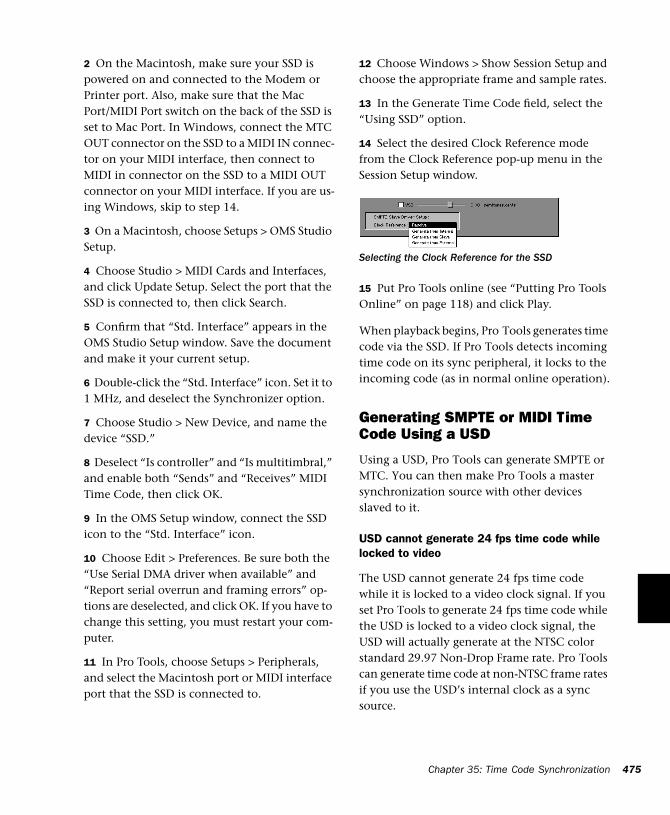
2 On the Macintosh, make sure your SSD is powered on and connected to the Modem or Printer port. Also, make sure that the Mac Port/MIDI Port switch on the back of the SSD is set to Mac Port. In Windows, connect the MTC OUT connector on the SSD to a MIDI IN connec-tor on your MIDI interface, then connect to MIDI in connector on the SSD to a MIDI OUT connector on your MIDI interface. If you are us-ing Windows, skip to step 14.
3 On a Macintosh, choose Setups > OMS Studio Setup.
4 Choose Studio > MIDI Cards and Interfaces, and click Update Setup. Select the port that the SSD is connected to, then click Search.
5 Confirm that “Std. Interface” appears in the OMS Studio Setup window. Save the document and make it your current setup.
6 Double-click the “Std. Interface” icon. Set it to 1 MHz, and deselect the Synchronizer option.
7 Choose Studio > New Device, and name the device “SSD.”
8 Deselect “Is controller” and “Is multitimbral,” and enable both “Sends” and “Receives” MIDI Time Code, then click OK.
9 In the OMS Setup window, connect the SSD icon to the “Std. Interface” icon.
10 Choose Edit > Preferences. Be sure both the “Use Serial DMA driver when available” and “Report serial overrun and framing errors” op-tions are deselected, and click OK. If you have to change this setting, you must restart your com-puter.
11 In Pro Tools, choose Setups > Peripherals, and select the Macintosh port or MIDI interface port that the SSD is connected to.
12 Choose Windows > Show Session Setup and choose the appropriate frame and sample rates.
13 In the Generate Time Code field, select the “Using SSD” option.
14 Select the desired Clock Reference mode from the Clock Reference pop-up menu in the Session Setup window.
15 Put Pro Tools online (see “Putting Pro Tools Online” on page 118) and click Play.
When playback begins, Pro Tools generates time code via the SSD. If Pro Tools detects incoming time code on its sync peripheral, it locks to the incoming code (as in normal online operation).
Generating SMPTE or MIDI Time Code Using a USD
Using a USD, Pro Tools can generate SMPTE or MTC. You can then make Pro Tools a master synchronization source with other devices slaved to it.
USD cannot generate 24 fps time code while locked to video
The USD cannot generate 24 fps time code while it is locked to a video clock signal. If you set Pro Tools to generate 24 fps time code while the USD is locked to a video clock signal, the USD will actually generate at the NTSC color standard 29.97 Non-Drop Frame rate. Pro Tools can generate time code at non-NTSC frame rates if you use the USD’s internal clock as a sync source.
Selecting the Clock Reference for the SSD
Chapter 35: Time Code Synchronization 475
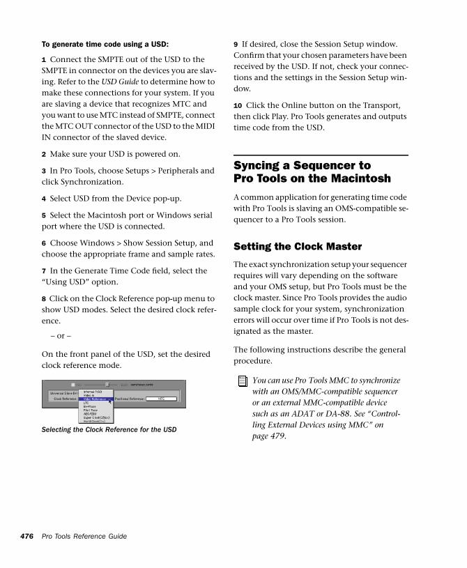
476
To generate time code using a USD:
1 Connect the SMPTE out of the USD to the SMPTE in connector on the devices you are slav-ing. Refer to the USD Guide to determine how to make these connections for your system. If you are slaving a device that recognizes MTC and you want to use MTC instead of SMPTE, connect the MTC OUT connector of the USD to the MIDI IN connector of the slaved device.
2 Make sure your USD is powered on.
3 In Pro Tools, choose Setups > Peripherals and click Synchronization.
4 Select USD from the Device pop-up.
5 Select the Macintosh port or Windows serial port where the USD is connected.
6 Choose Windows > Show Session Setup, and choose the appropriate frame and sample rates.
7 In the Generate Time Code field, select the “Using USD” option.
8 Click on the Clock Reference pop-up menu to show USD modes. Select the desired clock refer-ence.
– or –
On the front panel of the USD, set the desired clock reference mode.
Selecting the Clock Reference for the USD
Pro Tools Reference Guide
9 If desired, close the Session Setup window. Confirm that your chosen parameters have been received by the USD. If not, check your connec-tions and the settings in the Session Setup win-dow.
10 Click the Online button on the Transport, then click Play. Pro Tools generates and outputs time code from the USD.
Syncing a Sequencer to Pro Tools on the MacintoshA common application for generating time code with Pro Tools is slaving an OMS-compatible se-quencer to a Pro Tools session.
Setting the Clock Master
The exact synchronization setup your sequencer requires will vary depending on the software and your OMS setup, but Pro Tools must be the clock master. Since Pro Tools provides the audio sample clock for your system, synchronization errors will occur over time if Pro Tools is not des-ignated as the master.
The following instructions describe the general procedure.
You can use Pro Tools MMC to synchronize with an OMS/MMC-compatible sequencer or an external MMC-compatible device such as an ADAT or DA-88. See “Control-ling External Devices using MMC” on page 479.
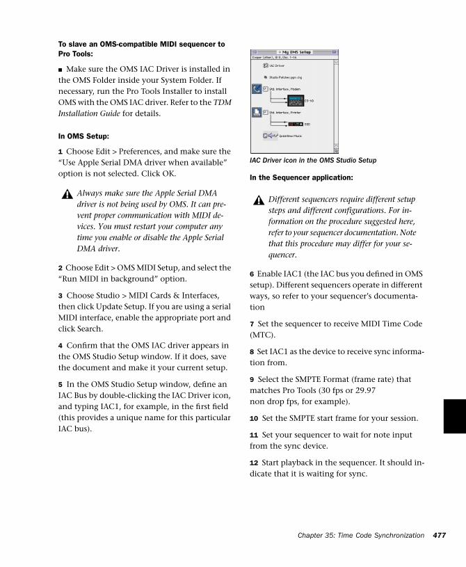
To slave an OMS-compatible MIDI sequencer to Pro Tools:
■ Make sure the OMS IAC Driver is installed in the OMS Folder inside your System Folder. If necessary, run the Pro Tools Installer to install OMS with the OMS IAC driver. Refer to the TDM Installation Guide for details.
In OMS Setup:
1 Choose Edit > Preferences, and make sure the “Use Apple Serial DMA driver when available” option is not selected. Click OK.
2 Choose Edit > OMS MIDI Setup, and select the “Run MIDI in background” option.
3 Choose Studio > MIDI Cards & Interfaces, then click Update Setup. If you are using a serial MIDI interface, enable the appropriate port and click Search.
4 Confirm that the OMS IAC driver appears in the OMS Studio Setup window. If it does, save the document and make it your current setup.
5 In the OMS Studio Setup window, define an IAC Bus by double-clicking the IAC Driver icon, and typing IAC1, for example, in the first field (this provides a unique name for this particular IAC bus).
Always make sure the Apple Serial DMA driver is not being used by OMS. It can pre-vent proper communication with MIDI de-vices. You must restart your computer any time you enable or disable the Apple Serial DMA driver.
In the Sequencer application:
6 Enable IAC1 (the IAC bus you defined in OMS setup). Different sequencers operate in different ways, so refer to your sequencer’s documenta-tion
7 Set the sequencer to receive MIDI Time Code (MTC).
8 Set IAC1 as the device to receive sync informa-tion from.
9 Select the SMPTE Format (frame rate) that matches Pro Tools (30 fps or 29.97 non drop fps, for example).
10 Set the SMPTE start frame for your session.
11 Set your sequencer to wait for note input from the sync device.
12 Start playback in the sequencer. It should in-dicate that it is waiting for sync.
IAC Driver icon in the OMS Studio Setup
Different sequencers require different setup steps and different configurations. For in-formation on the procedure suggested here, refer to your sequencer documentation. Note that this procedure may differ for your se-quencer.
Chapter 35: Time Code Synchronization 477
478
In Pro Tools:
13 Select Operations > Active in Background.
14 Choose Windows > Show Session Setup.
15 In the Session Setup window, choose an ap-propriate frame rate.
16 Select the SMPTE Start Frame to match the start frame in your sequencer. If the sequence starts at 00:01:00:00, you could set the Pro Tools Session to start earlier (for example, at 00:59:58:00) to allow some pre-roll.
17 Enable the MTC to Port option in the Output Time Code box. Select IAC1 as the MTC destina-tion.
18 Click Play or press the Spacebar to start play-back. Pro Tools will send MIDI Time Code to the sequencer via the IAC port and trigger synchro-nized playback. Click Stop in the Transport or press the Space bar again to stop playback.
Once synchronized playback is operating cor-rectly, you can record new takes in Pro Tools while listening to MIDI playback from your se-quencer. Follow the procedure described above for synchronized playback, then record new ma-terial in Pro Tools by following the recording procedures in the Recording section of this manual.
You should also be able to record new MIDI tracks while the sequencer is slaved to Pro Tools. See your sequencer documenta-tion for details on recording while the se-quencer is in an external synchronization mode.
Pro Tools Reference Guide
Syncing a Sequencer to Pro Tools in Windows
To synchronize Pro Tools to a Windows sequencer:
1 Make sure your MIDI interface is correctly in-stalled and configured. You must do this before proceeding.
2 Choose one pair of input/output ports on your MIDI interface to use as your sync “loop” for application-to-application MIDI communi-cation.
3 Connect a MIDI cable from that port’s output to the same port’s input (for example, port 1 out to port 1 in).
4 In Pro Tools, select the appropriate in/out ports when making your selections for MIDI source and/or destination ports.
• If you are slaving your sequencer to Pro Tools, select the appropriate port in the Session Setup window’s MTC to Port pop-up menu.
• If you are slaving Pro Tools to your sequencer, select the appropriate port in the Pro Tools Pe-ripherals > Synchronization window.
5 In your sequencer, select the appropriate in/out ports for MTC source/destination.
These instructions require the use of a phys-ical MIDI port. While several “virtual” MIDI cable applications do exist for inter-application MIDI communication in Win-dows, such software devices have not been qualified to work with Pro Tools.
Using MIDI Machine ControlPro Tools provides the capability to transmit lo-cation information to external devices, and to control their transports, using MIDI Machine Control (MMC).
Controlling External Devices using MMC
Any device that supports MMC (such as an Ale-sis ADAT or Tascam DA-88) can be controlled di-rectly from within Pro Tools, with either the de-vice or Pro Tools acting as clock master.
The external devices supported by Pro Tools im-plement “open loop” communications only. Be-cause of this, while Pro Tools is the transport master, any direct operation of the receiving de-vice’s transport will not be communicated back to Pro Tools. Instead, you can use the Transport pop-up to select the external device (MMC in the pop-up) and use the Pro Tools on-screen transport controls to drive the device.
Pro Tools does not support remote track arming of MMC-controlled external devices. You need to manually arm tracks for recording on the ex-ternal device.
Digidesign’s MachineControl option sup-ports remote track arming for Sony 9-pin and V-LAN enabled devices. See “Remote Track Arming” on page 481.
Macintosh
Pro Tools on the Macintosh uses OMS to facili-tate MIDI Machine Control. In order to use MMC with Pro Tools you must configure your MMC device to “Receive” and “Send” MIDI Ma-chine Control in OMS. For details, see “Using MMC to Sync an ADAT to Pro Tools on the Mac-intosh” on page 481.
Windows
Pro Tools in Windows uses your Multimedia Setup to determine which MIDI devices are available, and what their properties are. Refer to your device’s installation and usage documenta-tion to properly configure the device.
Enabling MIDI Machine Control in Pro Tools
To enable MIDI Machine Control:
1 Choose Setups > Peripherals, then click Syn-chronization.
2 Select your synchronization peripheral from the Synchronization/Device pop-up. If you are using a MIDI interface, select “Generic MTC Reader.”
If using a USD or SSD, set the Port to Any.
3 Select the appropriate port for synchroniza-tion information. This is the port to which your synchronization peripheral is attached.
By using the OMS IAC bus, you can also make a MIDI sequencer act as location master. Refer to your OMS and MMC-com-patible device documentation for details.
Chapter 35: Time Code Synchronization 479
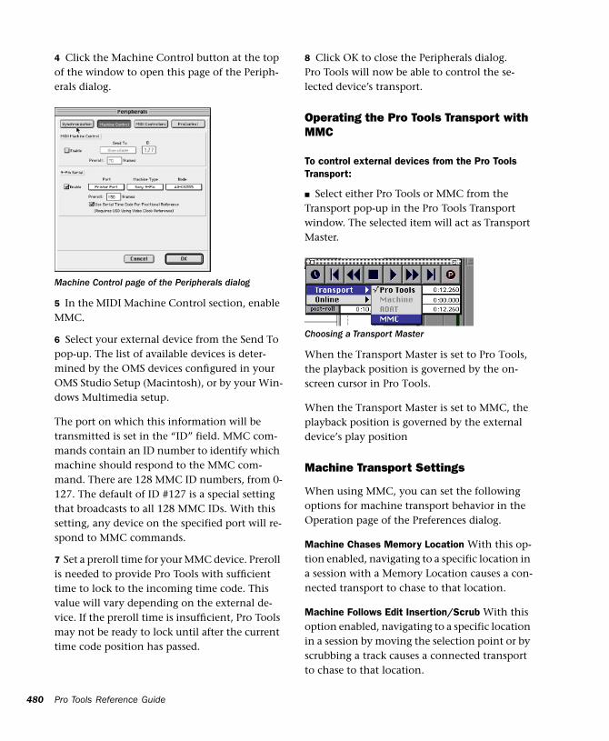
480
4 Click the Machine Control button at the top of the window to open this page of the Periph-erals dialog.
5 In the MIDI Machine Control section, enable MMC.
6 Select your external device from the Send To pop-up. The list of available devices is deter-mined by the OMS devices configured in your OMS Studio Setup (Macintosh), or by your Win-dows Multimedia setup.
The port on which this information will be transmitted is set in the “ID” field. MMC com-mands contain an ID number to identify which machine should respond to the MMC com-mand. There are 128 MMC ID numbers, from 0-127. The default of ID #127 is a special setting that broadcasts to all 128 MMC IDs. With this setting, any device on the specified port will re-spond to MMC commands.
7 Set a preroll time for your MMC device. Preroll is needed to provide Pro Tools with sufficient time to lock to the incoming time code. This value will vary depending on the external de-vice. If the preroll time is insufficient, Pro Tools may not be ready to lock until after the current time code position has passed.
Machine Control page of the Peripherals dialog
Pro Tools Reference Guide
8 Click OK to close the Peripherals dialog. Pro Tools will now be able to control the se-lected device’s transport.
Operating the Pro Tools Transport with MMC
To control external devices from the Pro Tools Transport:
■ Select either Pro Tools or MMC from the Transport pop-up in the Pro Tools Transport window. The selected item will act as Transport Master.
When the Transport Master is set to Pro Tools, the playback position is governed by the on-screen cursor in Pro Tools.
When the Transport Master is set to MMC, the playback position is governed by the external device’s play position
Machine Transport Settings
When using MMC, you can set the following options for machine transport behavior in the Operation page of the Preferences dialog.
Machine Chases Memory Location With this op-tion enabled, navigating to a specific location in a session with a Memory Location causes a con-nected transport to chase to that location.
Machine Follows Edit Insertion/Scrub With this option enabled, navigating to a specific location in a session by moving the selection point or by scrubbing a track causes a connected transport to chase to that location.
Choosing a Transport Master
Remote Track ArmingDigidesign’s MachineControl™ option for Pro Tools allows you to remotely arm tracks on supported 9-pin or V-LAN decks. Without Ma-chineControl, Pro Tools does not support re-mote track arming of external devices. Machine-Control is a DAE Extension that allows Pro Tools to act as the master or slave to external Sony 9-pin or V-LAN machines, in addition to provid-ing remote track arming from within Pro Tools. Contact your Digidesign Dealer for information about the MachineControl option.
Setting Minimum Sync Delay
Lock up delay is the amount of time your sys-tem’s devices need to achieve synchronization “lock.” This amount varies for each device. Pro Tools lock up delay is set by entering a value for Minimum Sync Delay in the Synchroniza-tion window of the Peripherals dialog. The min-imum delay is 15 frames. Find the shortest pos-sible lock-up time that your equipment can operates at consistently, and set this as the Min-imum Sync Delay. On some machines, enabling the Use Serial time code setting will make ma-chines lock up much faster.
Configuring Minimum Sync Delay for External MMC Devices Locked to House Sync
When controlling a house-synced device from Pro Tools via MMC, the device will first lock to the MMC location and then align the color framing. Within house sync code are 4 frames for ensuring color frame lock. If the minimum synchronization set up time is less than the time required to achieve both location and color frame lock, playback will begin before the de-
vice has aligned the color frames. In this sce-nario, you should set the Minimum Sync Delay to be more than the time required for color frame lock. This is not a problem with the USD, which will drop out of lock until the color frame is locked.
Using MMC to Sync an ADAT to Pro Tools on the Macintosh
The following section presents an example of how you can use MMC to slave an ADAT to Pro Tools on a Macintosh using OMS.
Setup Description:
Hardware: Pro Tools system (Macintosh), Op-code Studio 64X MIDI Interface, JL Cooper DataSync II, Alesis ADAT.
Software: Pro Tools, OMS
Cable Connections: The Studio 64X’s Mac/Serial port is connected to one of the CPU serial ports (Modem or Printer). MIDI In and MIDI OUT connections are made between the appropriate ports of the 64X and the MIDI IN/MIDI OUT ports of the JL Cooper DataMaster. Sync (9-pin) In/Out connections are made between the JL Cooper DataMaster and the ADAT.
In OMS Setup:
1 Make sure the OMS IAC Driver is installed and configured. See “Syncing a Sequencer to Pro Tools on the Macintosh” on page 476 for more information.
2 Define a new device for the JL Cooper DataSync II and the ADAT.
Chapter 35: Time Code Synchronization 481
482
3 Configure the JL Cooper device by double-clicking its icon in the OMS Studio Setup win-dow. For the JL Cooper DataMaster, enable Is Controller, then enable both Sends and Receives MIDI Time Code. (Be sure to leave Is Multitim-bral unchecked.) Select channel 1 as the Receive Channel.
4 Configure the ADAT OMS device by double-clicking its icon. Leave Is Controller and Is Mul-titimbral unchecked (disabled). Enable both “Sends” and “Receives” MIDI Time Code and MIDI Machine Control. You do not need to have any Receive channels enabled.
5 Save/Make Current and then close the new OMS Studio Setup.
In Pro Tools
6 Choose Setups > Peripherals and click Syn-chronization.
7 Select Generic MTC Reader as the Synchroni-zation device (this represents the 64X), then se-lect the port to which your MIDI Interface is connected to (in this example, the port choice would appear as “Studio64X / Printer.”)
8 Open the Machine Control window of the Pe-ripherals dialog. In the MIDI Machine Control section, enable MMC, then select JLCooper DataMaster as the Send To destination.
9 Set the ID to 127 (this is the “broadcast to all” setting, and the Pro Tools default setting for MMC device ID).
10 Choose Windows > Show Session Setup.
11 In the Session Setup Window, set the frame rate and start frame as appropriate.
Pro Tools Reference Guide
12 Enable the MTC to Port option (click in the box so that it is enabled), then select JLCooper DataMaster in the pop-up next to MTC to Port. This routes MIDI Time Code from Pro Tools to the JLCooper. device, which then sends the data on to the ADAT.
13 Close the Session Setup window.
14 Click Play or press the Spacebar. The ADAT will cue to the play point and begin playing back in sync with Pro Tools. You do not need to put Pro Tools online to control the ADAT.
15 To control the ADAT from the Pro Tools Transport, select MMC from the Transport pop-up (in the Transport window). Pressing Play, Re-wind, FFWD, RTZ or Go To End will cause the ADAT to respond accordingly.
External Hardware Configuration
This example uses the JL Cooper DataSync II, which must be configured correctly for the above to work. Configure the ADAT as a slave (not master), enable MTC as the sync source, and enable MIDI Machine Control. The ADAT must be set to Internal mode. Consult the docu-mentation that came with these devices for more details. If you are using a Digidesign ADAT Bridge I/O, refer to the ADAT Bridge I/O User’s Guide for additional information.
Syncing Pro Tools to an OMS-Compatible Sequencer using MMC(Macintosh Only)
You can “lock” a MIDI sequencer to Pro Tools for synchronized operation, while using the se-quencer as the transport and location master. In this case, Pro Tools is still the system clock mas-ter, while the sequencer is the transport/loca-tion master.
MMC and OMS Synchronization
When using MIDI Machine Control, you must have the OMS-compatible sequencer configured to synchronize to Pro Tools using the OMS IAC Driver (see “Syncing a Sequencer to Pro Tools on the Macintosh” on page 476). When controlled by a sequencer via MMC, Pro Tools serves as clock master for the sequencer.
Pro Tools also serves as a transport and location slave to the sequencer. When starting and stop-ping playback in the sequencer, the sequencer sends out location information to Pro Tools via MMC commands. Pro Tools then cues to the lo-cation, begins playback, and sends MIDI Time Code back to the sequencer. The sequencer then locks to the MIDI Time Code from Pro Tools for synchronized playback.
The following instructions describe the general steps that you should take. The exact synchroni-zation setup your sequencer requires will vary depending on the software and your specific MIDI setup.
To slave the Pro Tools transport to an OMS-compatible MIDI sequencer using MIDI Machine Control:
1 Make sure the OMS IAC Driver is installed in the OMS Folder inside your System Folder. If necessary, run the OMS Installer and choose Custom Install to install the OMS IAC driver.
2 In Pro Tools, choose Setups > OMS Studio Setup to launch the OMS Setup application.
In OMS Setup:
3 Choose Edit > Preferences, make sure the “Use Serial DMA driver when available” option is de-selected, and click OK.
4 Choose Edit > OMS MIDI Setup, make sure the “Run MIDI in background” option is selected, and click OK.
5 Choose Studio > MIDI Cards & Interfaces, then click Update Setup. If you are using a serial MIDI interface, enable the appropriate port and click Search.
6 Confirm that the OMS IAC driver appears in the OMS Studio Setup window. Save the setup document and make it your current setup.
7 In the OMS Studio Setup window, define two IAC busses by double-clicking the IAC Driver, then naming the first field “IAC1” and the sec-ond field “MMC.”
In your sequencer:
8 Enable IAC1 as a MIDI device.
9 Set your sequencer to receive MTC from IAC1, and enable remote control of the applciation.
10 Configure the frame rate to match your Pro Tools session. Click OK to close the Sync Op-tions dialog.
Chapter 35: Time Code Synchronization 483
484
11 Set a sequence start time (01:00:00:00 for ex-ample). The Offset at the top of the Sequence window should usually match the Offset in Pro Tools.
12 Set the sequencer to wait for MIDI note in-formation (“wait for note”).
13 Start playback in the sequencer. The se-quencer should indicate that it is waiting for note information.
In Pro Tools:
14 Choose MIDI > Enable Input Devices. Select the IAC bus transmitting the MMC messages and click OK.
15 Choose Operations > Active in Background.
16 Choose Windows > Show Session Setup, and choose the appropriate frame rate and SMPTE Start Frame to match the start time in your se-quencer.
17 In the Output Time Code section of the Ses-sion Setup window, enable the MTC to Port op-tion. In the pop-up menu just below the MTC to Port option, choose IAC1. You can now close the Session Setup window, or leave it open (settings are active as soon as they are enabled in the Ses-sion Setup window).
18 Next, choose Setups > Peripherals, and open the Synchronization page of the Peripherals di-alog.
19 First, select Generic MTC Reader as the syn-chronization device, and select Any as the port.
Pro Tools Reference Guide
20 Next, click to Enable Control of Pro Tools via MMC, and set the ID to 0.
In the Sequencer:
21 Engage any of the following Transport func-tions: Play, Stop, Fast Forward, Rewind, Record, or Locate (Cue). The sequencer sends MIDI Ma-chine Control commands to Pro Tools via the IAC bus, and Pro Tools follows.
When starting and stopping playback in the se-quencer, the sequencer sends location informa-tion to Pro Tools via MIDI Machine Control commands. Pro Tools cues to the location, be-gins playback, and in turn sends MIDI Time Code back to the sequencer. The sequencer then locks to the MIDI Time Code from Pro Tools for synchronized playback.
If MMC is currently enabled in the Pro Tools Peripherals > Machine Control dialog, you must assign a unique ID num-ber in both of the corresponding MMC ID# fields. If not, an MMC feedback loop will occur. This can also happen if you use the default “broadcast to all” ID number of 127 in both places. If you are only slaving Pro Tools to a sequencer via MMC, without an external device requiring MMC from Pro Tools, you should disable MMC entirely in the Machine Control window.
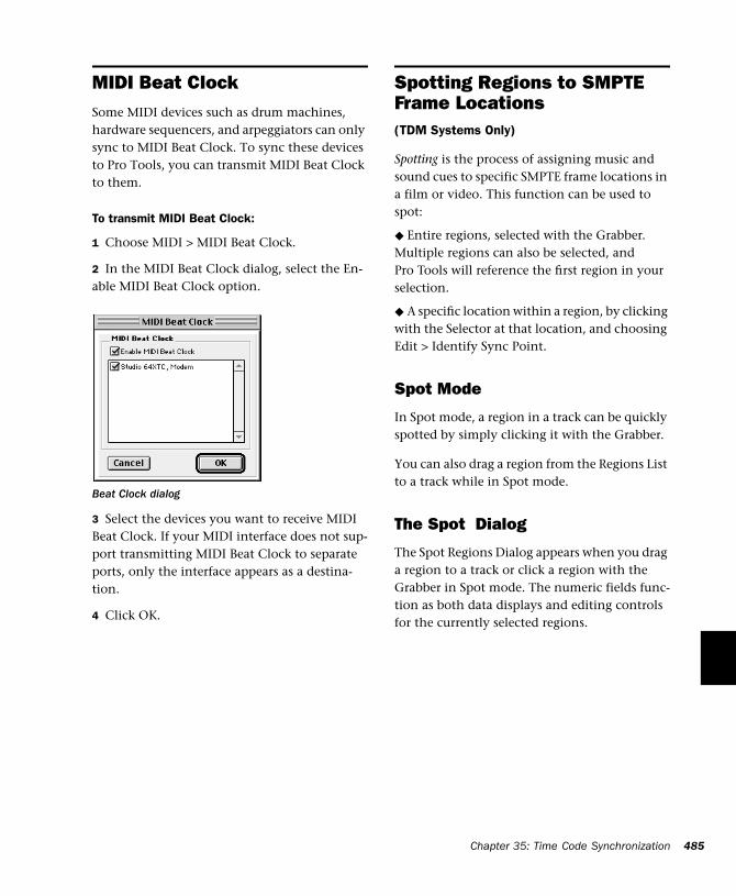
MIDI Beat ClockSome MIDI devices such as drum machines, hardware sequencers, and arpeggiators can only sync to MIDI Beat Clock. To sync these devices to Pro Tools, you can transmit MIDI Beat Clock to them.
To transmit MIDI Beat Clock:
1 Choose MIDI > MIDI Beat Clock.
2 In the MIDI Beat Clock dialog, select the En-able MIDI Beat Clock option.
3 Select the devices you want to receive MIDI Beat Clock. If your MIDI interface does not sup-port transmitting MIDI Beat Clock to separate ports, only the interface appears as a destina-tion.
4 Click OK.
Beat Clock dialog
Spotting Regions to SMPTE Frame Locations(TDM Systems Only)
Spotting is the process of assigning music and sound cues to specific SMPTE frame locations in a film or video. This function can be used to spot:
◆ Entire regions, selected with the Grabber. Multiple regions can also be selected, and Pro Tools will reference the first region in your selection.
◆ A specific location within a region, by clicking with the Selector at that location, and choosing Edit > Identify Sync Point.
Spot Mode
In Spot mode, a region in a track can be quickly spotted by simply clicking it with the Grabber.
You can also drag a region from the Regions List to a track while in Spot mode.
The Spot Dialog
The Spot Regions Dialog appears when you drag a region to a track or click a region with the Grabber in Spot mode. The numeric fields func-tion as both data displays and editing controls for the currently selected regions.
Chapter 35: Time Code Synchronization 485
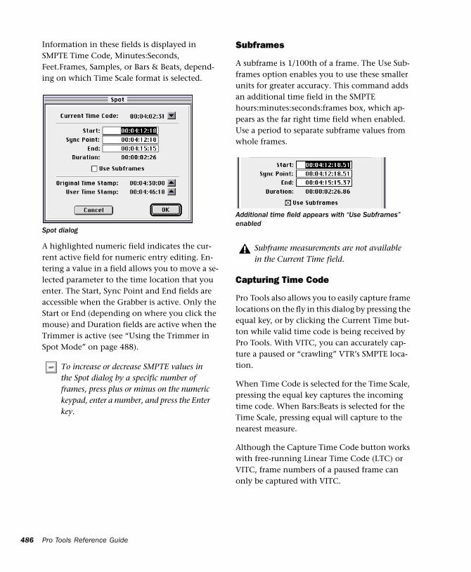
486
Information in these fields is displayed in SMPTE Time Code, Minutes:Seconds, Feet.Frames, Samples, or Bars & Beats, depend-ing on which Time Scale format is selected.
A highlighted numeric field indicates the cur-rent active field for numeric entry editing. En-tering a value in a field allows you to move a se-lected parameter to the time location that you enter. The Start, Sync Point and End fields are accessible when the Grabber is active. Only the Start or End (depending on where you click the mouse) and Duration fields are active when the Trimmer is active (see “Using the Trimmer in Spot Mode” on page 488).
Spot dialog
To increase or decrease SMPTE values in the Spot dialog by a specific number of frames, press plus or minus on the numeric keypad, enter a number, and press the Enter key.
Pro Tools Reference Guide
Subframes
A subframe is 1/100th of a frame. The Use Sub-frames option enables you to use these smaller units for greater accuracy. This command adds an additional time field in the SMPTE hours:minutes:seconds:frames box, which ap-pears as the far right time field when enabled. Use a period to separate subframe values from whole frames.
Capturing Time Code
Pro Tools also allows you to easily capture frame locations on the fly in this dialog by pressing the equal key, or by clicking the Current Time but-ton while valid time code is being received by Pro Tools. With VITC, you can accurately cap-ture a paused or “crawling” VTR’s SMPTE loca-tion.
When Time Code is selected for the Time Scale, pressing the equal key captures the incoming time code. When Bars:Beats is selected for the Time Scale, pressing equal will capture to the nearest measure.
Although the Capture Time Code button works with free-running Linear Time Code (LTC) or VITC, frame numbers of a paused frame can only be captured with VITC.
Additional time field appears with “Use Subframes” enabled
Subframe measurements are not available in the Current Time field.
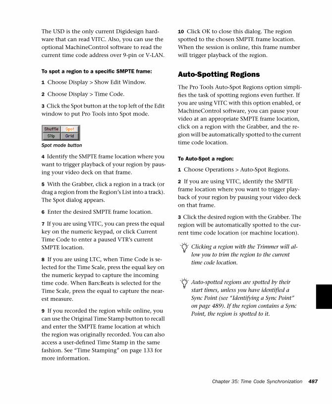
The USD is the only current Digidesign hard-ware that can read VITC. Also, you can use the optional MachineControl software to read the current time code address over 9-pin or V-LAN.
To spot a region to a specific SMPTE frame:
1 Choose Display > Show Edit Window.
2 Choose Display > Time Code.
3 Click the Spot button at the top left of the Edit window to put Pro Tools into Spot mode.
4 Identify the SMPTE frame location where you want to trigger playback of your region by paus-ing your video deck on that frame.
5 With the Grabber, click a region in a track (or drag a region from the Region’s List into a track). The Spot dialog appears.
6 Enter the desired SMPTE frame location.
7 If you are using VITC, you can press the equal key on the numeric keypad, or click Current Time Code to enter a paused VTR’s current SMPTE location.
8 If you are using LTC, when Time Code is se-lected for the Time Scale, press the equal key on the numeric keypad to capture the incoming time code. When Bars:Beats is selected for the Time Scale, press the equal to capture the near-est measure.
9 If you recorded the region while online, you can use the Original Time Stamp button to recall and enter the SMPTE frame location at which the region was originally recorded. You can also access a user-defined Time Stamp in the same fashion. See “Time Stamping” on page 133 for more information.
Spot mode button
10 Click OK to close this dialog. The region spotted to the chosen SMPTE frame location. When the session is online, this frame number will trigger playback of the region.
Auto-Spotting Regions
The Pro Tools Auto-Spot Regions option simpli-fies the task of spotting regions even further. If you are using VITC with this option enabled, or MachineControl software, you can pause your video at an appropriate SMPTE frame location, click on a region with the Grabber, and the re-gion will be automatically spotted to the current time code location.
To Auto-Spot a region:
1 Choose Operations > Auto-Spot Regions.
2 If you are using VITC, identify the SMPTE frame location where you want to trigger play-back of your region by pausing your video deck on that frame.
3 Click the desired region with the Grabber. The region will be automatically spotted to the cur-rent time code location (or machine location).
Clicking a region with the Trimmer will al-low you to trim the region to the current time code location.
Auto-spotted regions are spotted by their start times, unless you have identified a Sync Point (see “Identifying a Sync Point” on page 489). If the region contains a Sync Point, the region is spotted to it.
Chapter 35: Time Code Synchronization 487
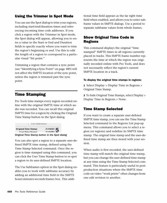
488
Using the Trimmer in Spot Mode
You can use the Spot dialog to trim your regions, including start/end/duration times and refer-encing incoming time code addresses. If you click a region with the Trimmer in Spot mode, the Spot dialog will appear, allowing you to en-ter a value in the Start or End and Duration fields to specify exactly where you want to trim the region’s beginning or end. Use this to edit the length of a region to correspond to a partic-ular visual “hit point.”
Trimming a region that contains a sync point (see “Identifying a Sync Point” on page 489) will not affect the SMPTE location of the sync point, unless the region is trimmed past the sync point.
Time StampingPro Tools time stamps every region recorded on-line with the original SMPTE time at which au-dio was recorded. You can recall this original SMPTE time for a region by clicking the Original Time Stamp button in the Spot dialog.
You can also spot a region to a separate user-de-fined SMPTE time stamp, defined using the Time Stamp Selected command. Once the re-gion is time stamped using this command, you can click the User Time Stamp button to re-spot a region to its user-defined SMPTE location.
The Use Subframes option in the Spot dialog en-ables you to work with subframe accuracy by adding an additional time field in the SMPTE hours:minutes:seconds:frames box. This addi-
Original Time Stamp button in the Spot dialog
Pro Tools Reference Guide
tional time field appears as the far right time field when enabled, and allows you to enter sub-frame values in SMPTE dialogs. Use a period to separate subframe values from whole frames.
Show Original Time Code in Regions
This command displays the original “time stamped” SMPTE times in all regions currently placed in tracks. This SMPTE frame number rep-resents the time at which the region was origi-nally recorded online with Pro Tools, and does not necessarily reflect the region’s current SMPTE location in a track.
To display the original time stamps in regions:
1 Select Display > Display Time in Regions > Original Time Stamp.
2 To hide Original Time Stamps, select Display > Display Time in Regions > None.
Time Stamp Selected
If you want to create a separate user-defined SMPTE time stamp, you can use the Time Stamp Selected command in the Regions List pop-up menu. This command allows you to select a re-gion (or regions) and redefine its SMPTE time stamp. The original time stamp and the user-de-fined time stamp are then stored with your ses-sion.
When audio is first recorded, the user-defined time stamp will match the original time stamp, but you can change the user-defined time stamp at any time using the Time Stamp Selected com-mand. This feature is particularly useful in post-production situations where the SMPTE time code on video “work prints” often changes from one edit revision to another.
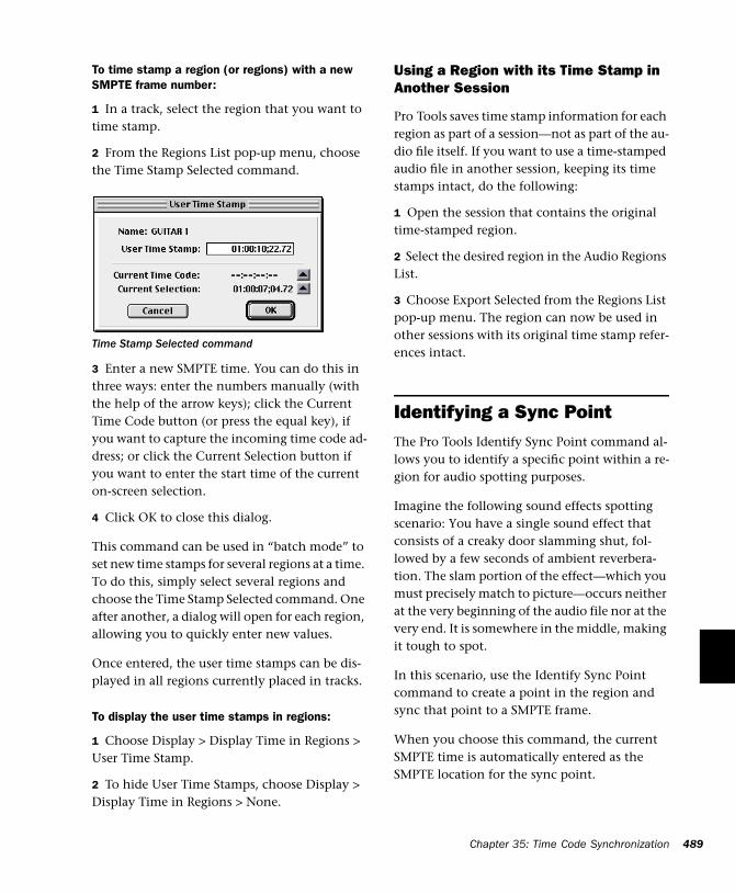
To time stamp a region (or regions) with a new SMPTE frame number:
1 In a track, select the region that you want to time stamp.
2 From the Regions List pop-up menu, choose the Time Stamp Selected command.
3 Enter a new SMPTE time. You can do this in three ways: enter the numbers manually (with the help of the arrow keys); click the Current Time Code button (or press the equal key), if you want to capture the incoming time code ad-dress; or click the Current Selection button if you want to enter the start time of the current on-screen selection.
4 Click OK to close this dialog.
This command can be used in “batch mode” to set new time stamps for several regions at a time. To do this, simply select several regions and choose the Time Stamp Selected command. One after another, a dialog will open for each region, allowing you to quickly enter new values.
Once entered, the user time stamps can be dis-played in all regions currently placed in tracks.
To display the user time stamps in regions:
1 Choose Display > Display Time in Regions > User Time Stamp.
2 To hide User Time Stamps, choose Display > Display Time in Regions > None.
Time Stamp Selected command
Using a Region with its Time Stamp in Another Session
Pro Tools saves time stamp information for each region as part of a session—not as part of the au-dio file itself. If you want to use a time-stamped audio file in another session, keeping its time stamps intact, do the following:
1 Open the session that contains the original time-stamped region.
2 Select the desired region in the Audio Regions List.
3 Choose Export Selected from the Regions List pop-up menu. The region can now be used in other sessions with its original time stamp refer-ences intact.
Identifying a Sync PointThe Pro Tools Identify Sync Point command al-lows you to identify a specific point within a re-gion for audio spotting purposes.
Imagine the following sound effects spotting scenario: You have a single sound effect that consists of a creaky door slamming shut, fol-lowed by a few seconds of ambient reverbera-tion. The slam portion of the effect—which you must precisely match to picture—occurs neither at the very beginning of the audio file nor at the very end. It is somewhere in the middle, making it tough to spot.
In this scenario, use the Identify Sync Point command to create a point in the region and sync that point to a SMPTE frame.
When you choose this command, the current SMPTE time is automatically entered as the SMPTE location for the sync point.
Chapter 35: Time Code Synchronization 489
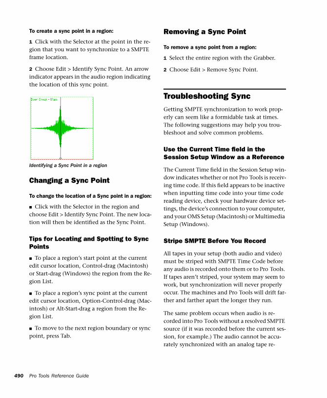
490
To create a sync point in a region:
1 Click with the Selector at the point in the re-gion that you want to synchronize to a SMPTE frame location.
2 Choose Edit > Identify Sync Point. An arrow indicator appears in the audio region indicating the location of this sync point.
Changing a Sync Point
To change the location of a Sync point in a region:
■ Click with the Selector in the region and choose Edit > Identify Sync Point. The new loca-tion will then be identified as the Sync Point.
Tips for Locating and Spotting to Sync Points
■ To place a region’s start point at the current edit cursor location, Control-drag (Macintosh) or Start-drag (Windows) the region from the Re-gion List.
■ To place a region’s sync point at the current edit cursor location, Option-Control-drag (Mac-intosh) or Alt-Start-drag a region from the Re-gion List.
■ To move to the next region boundary or sync point, press Tab.
Identifying a Sync Point in a region
Pro Tools Reference Guide
Removing a Sync Point
To remove a sync point from a region:
1 Select the entire region with the Grabber.
2 Choose Edit > Remove Sync Point.
Troubleshooting SyncGetting SMPTE synchronization to work prop-erly can seem like a formidable task at times. The following suggestions may help you trou-bleshoot and solve common problems.
Use the Current Time field in the Session Setup Window as a Reference
The Current Time field in the Session Setup win-dow indicates whether or not Pro Tools is receiv-ing time code. If this field appears to be inactive when inputting time code into your time code reading device, check your hardware device set-tings, the device’s connection to your computer, and your OMS Setup (Macintosh) or Multimedia Setup (Windows).
Stripe SMPTE Before You Record
All tapes in your setup (both audio and video) must be striped with SMPTE Time Code before any audio is recorded onto them or to Pro Tools. If tapes aren’t striped, your system may seem to work, but synchronization will never properly occur. The machines and Pro Tools will drift far-ther and farther apart the longer they run.
The same problem occurs when audio is re-corded into Pro Tools without a resolved SMPTE source (if it was recorded before the current ses-sion, for example.) The audio cannot be accu-rately synchronized with an analog tape re-
corder or video tape deck, since the Pro Tools audio was not recorded referenced to the SMPTE time code from the analog tape deck or video tape deck.
Resolve All Components of Your System
When striping time code, make sure that the time code generator and the video record deck are resolved to the same crystal reference. For example, when striping 29.97 Drop Frame time code onto a VTR, both the SMPTE generator and the VTR should be resolved to the same “black burst” or house sync generator. During play-back, the master deck should be resolved to “black burst” or house sync.
This convention provides compatibility for your tape between the record and playback passes, and when it’s played back in other facilities on different equipment. This also means that when playing back a tape striped with time code, the playback deck should be resolved to the same sync rate as the record deck was resolved to at the time of the striping. When you stripe an au-dio transport with time code, it should be “free-running” and unresolved, but should be re-solved with a house sync-referenced synchro-nizer during playback.
Know the True Frame Rate on Your Work Tape
If you get your video tapes from a production company instead of recording them yourself, be absolutely sure that they indicate the SMPTE frame rate used on the tape correctly.
The Digidesign SSD and USD (and some third-party products) can be used to determine frame rate. See “Determining SMPTE Frame Rate” on page 471.
29.97 fps Non-Drop Rate Can Cause Problems
29.97 fps Non-Drop is a slightly slower version of 30 fps Non-Drop time code. When used with color video, each video frame now matches up with each SMPTE frame without having to use a drop-frame coding. This makes any frame num-ber mathematics much simpler, since no frame numbers are dropped.
Unfortunately, some hardware and software de-vices do not recognize 29.97 Non-Drop as a sep-arate frame rate. For example, any standard SMPTE-to MTC-converter does not explicitly recognize it. The user must tell the convertor to expect 30 fps Non-Drop instead. In fact, many devices that read SMPTE work acceptably by reading 29.97 Non-Drop if they are set to expect 30 fps Non-Drop.
Any SMPTE reader that uses the time code num-bers to make real-time calculations (as Pro Tools does when it tries to trigger and sync to SMPTE) also needs to know that the frame format is 29.97 and not 30 fps. Since Pro Tools allows this choice of frame rate this does not really pose a problem. The problem exists because many us-ers cannot readily distinguish 29.97 from 30 fps.
More importantly, some production companies will distribute video work prints striped with 29.97 fps but mark them as “30 fps NTSC,” by which they actually mean 29.97 fps Non-Drop. By the time you get the tape, you may have no idea what’s actually on it. Feeding 29.97 Non-Drop to Pro Tools when it’s set for 30 fps Non-Drop will result in timing errors of about 1.8 frames per minute, causing audio playback to trigger out of sync.
Chapter 35: Time Code Synchronization 491
492
Be Careful When Changing Frame Rates
If you change time code rates in the middle of a session, many SMPTE-to-MIDI Time Code con-verters need to be turned off and turned on again to be able to recognize the new frame rate.
Use a Consistent Clock Source
A sound file should be played back using the same peripheral and sample rate it was recorded with, if at all possible. This assures the closest match between record and playback sample rates. For example, if an audio file was recorded at 44.1 kHz with the Pro Tools Audio Interface then the Sample Rate should be set to 44.1 kHz during playback with the Audio Interface as well.
On a Macintosh, Disable AppleTalk, Network Connections, Screen Savers, and Power Saving Features
These types of software can cause the Macintosh to ignore MIDI data (such as MIDI Time Code) coming into its serial ports. Make sure AppleTalk is inactive in the Chooser, disconnect AppleTalk cables, and remove any network extensions from your System Folder.
In Windows, Disable Screen Savers and Power Management Features
These types of software can cause your com-puter to ignore MIDI data (such as MIDI Time Code).
Pro Tools Reference Guide
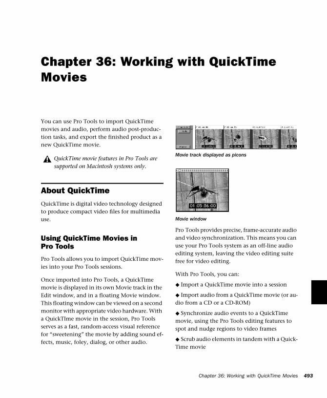
Chapter 36: Working with QuickTime Movies
You can use Pro Tools to import QuickTime movies and audio, perform audio post-produc-tion tasks, and export the finished product as a new QuickTime movie.
About QuickTimeQuickTime is digital video technology designed to produce compact video files for multimedia use.
Using QuickTime Movies in Pro Tools
Pro Tools allows you to import QuickTime mov-ies into your Pro Tools sessions.
Once imported into Pro Tools, a QuickTime movie is displayed in its own Movie track in the Edit window, and in a floating Movie window. This floating window can be viewed on a second monitor with appropriate video hardware. With a QuickTIme movie in the session, Pro Tools serves as a fast, random-access visual reference for “sweetening” the movie by adding sound ef-fects, music, foley, dialog, or other audio.
QuickTime movie features in Pro Tools are supported on Macintosh systems only.
Pro Tools provides precise, frame-accurate audio and video synchronization. This means you can use your Pro Tools system as an off-line audio editing system, leaving the video editing suite free for video editing.
With Pro Tools, you can:
◆ Import a QuickTime movie into a session
◆ Import audio from a QuickTime movie (or au-dio from a CD or a CD-ROM)
◆ Synchronize audio events to a QuickTime movie, using the Pro Tools editing features to spot and nudge regions to video frames
◆ Scrub audio elements in tandem with a Quick-Time movie
Movie track displayed as picons
Movie window
Chapter 36: Working with QuickTime Movies 493
494
◆ Use the Pro Tools Bounce to Movie command to compile a new “flattened” QuickTime movie file that can be read by any QuickTime-compat-ible application
Because Pro Tools has no video editing capabili-ties of its own, if you want to edit or in any other way modify a movie, return to your video cap-ture and assembly environment (for example, Adobe Premiere) for editing, then import the ed-ited movie into Pro Tools.
Video Capture/Playback Cards
For professional applications where full-screen, 25/30 frames-per-second playback is critical, we recommend that you invest in a Digidesign-ap-proved third-party video capture and playback card. For the most up-to-date information about such products, contact your Digidesign dealer or visit Digidesign’s Web site.
If You Are New to Audio Post Production
If you are new to digital video, time code, or au-dio-for-post production, the following sugges-tions will help you manage your session’s audio and video requirements. Not all of these may apply to every project.
Plan ahead Think through your entire project before you start capturing your video. For best results when working with SMPTE time code, make sure that time code is burned into a win-dow in the movie. Try to anticipate compatibil-ity and configuration issues that may arise.
You can capture Avid-compatible video in Pro Tools with AVoption or AVoption XL.
Pro Tools Reference Guide
Conform Your Movie Be sure to conform your captured QuickTime movie to the desired frame rate. Consult your video capture software’s doc-umentation for information on how to ensure frame-accurate captures. We recommend that you do this to all video captures to ensure accu-rate playback in Pro Tools.
If your destination is a pulled-down Pro Tools session, this pull down affects QuickTime movie playback speed. You should conform your movie to a 30 fps frame rate for use in a pulled-down session.
Destined for video or film? What is the ultimate destination of your work? Is it for TV, film, au-dio CD or CD-ROM? This will determine such things as the best sample rate to use, the correct frame rate, pull-down or pull-up rates, and so on. Double-check the time code frame rate. You must make sure that you know the correct frame rate of the video source.
Storage Make sure you have enough disk space on your drive, and optimize your hard drives regularly.
Video compatibility If you are not digitizing the video material yourself (if the material is already on hard disk) check into the type of video cap-ture and playback system that was used and make sure you can accommodate that format’s compression method. Check whether or not time code is “burned into” or superimposed over a small area of the video.
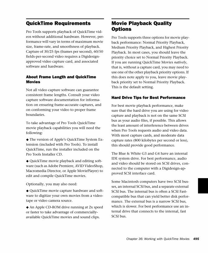
QuickTime RequirementsPro Tools supports playback of QuickTime vid-eos without additional hardware. However, per-formance will vary in terms of maximum movie size, frame-rate, and smoothness of playback. Capture of 30/25 fps (frames per second), 60/50 fields-per-second video requires a Digidesign-approved video capture card, and associated software and hardware.
About Frame Length and QuickTime Movies
Not all video capture software can guarantee consistent frame lengths. Consult your video capture software documentation for informa-tion on ensuring frame-accurate captures, and on conforming your video to proper frame boundaries.
To take advantage of Pro Tools QuickTime movie playback capabilities you will need the following:
◆ The version of Apple’s QuickTime System Ex-tension (included with Pro Tools). To install QuickTime, run the installer included on the Pro Tools Installer CD.
◆ QuickTime movie playback and editing soft-ware (such as Adobe Premiere, AVID VideoShop, Macromedia Director, or Apple MoviePlayer) to edit and compile QuickTime movies.
Optionally, you may also need:
◆ QuickTime movie capture hardware and soft-ware to digitize your own movies from a video-tape or video camera source.
◆ An Apple CD-ROM drive running at 2x speed or faster to take advantage of commercially-available QuickTime movies and sound clips.
Movie Playback Quality OptionsPro Tools supports three options for movie play-back performance: Normal Priority Playback, Medium Priority Playback, and Highest Priority Playback. In most cases, you should leave the priority choice set to Normal Priority Playback. If you are running QuickTime Movies natively, that is, without a capture card, you may need to use one of the other playback priority options. If this does note apply to you, leave movie play-back priority set to Normal Priority Playback. This is the default setting.
Hard Drive Tips for Best Performance
For best movie playback performance, make sure that the hard drive you are using for video capture and playback is not on the same SCSI bus as your audio files, if possible. This allows the least amount of interference between drives when Pro Tools requests audio and video data. With most capture cards, and moderate data capture rates (800 kilobytes per second or less), this should provide good performance.
The Blue & White G3 and G4 have an internal IDE system drive. For best performance, audio and video should be stored on SCSI drives, con-nected to the computer with a Digidesign-ap-proved SCSI interface card.
Some Macintosh computers have two SCSI bus-ses, an internal SCSI bus, and a separate external SCSI bus. The internal bus is often a SCSI Fast-compatible bus that can yield better disk perfor-mance. The external bus is a narrow SCSI bus, which is slower. For best performance use an in-ternal drive that connects to the internal, fast SCSI bus.
Chapter 36: Working with QuickTime Movies 495
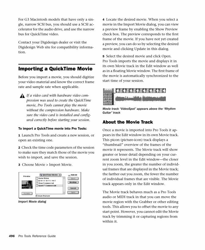
496
For G3 Macintosh models that have only a sin-gle, narrow SCSI bus, you should use a SCSI ac-celerator for the audio drive, and use the narrow bus for QuickTime video.
Contact your Digidesign dealer or visit the Digidesign Web site for compatibility informa-tion.
Importing a QuickTime MovieBefore you import a movie, you should digitize your video material and know the correct frame rate and sample rate when applicable.
To import a QuickTime movie into Pro Tools:
1 Launch Pro Tools and create a new session, or open an existing one.
2 Check the time code parameters of the session to make sure they match those of the movie you wish to import, and save the session.
3 Choose Movie > Import Movie.
If a video card with hardware video com-pression was used to create the QuickTime movie, Pro Tools cannot play the movie without the compression hardware. Make sure the video card is installed and config-ured correctly before starting your session.
Import Movie dialog
Pro Tools Reference Guide
4 Locate the desired movie. When you select a movie in the Import Movie dialog, you can view a preview frame by enabling the Show Preview check box. The preview corresponds to the first frame of the movie. If you have not yet created a preview, you can do so by selecting the desired movie and clicking Update in this dialog.
5 Select the desired movie and click Open. Pro Tools imports the movie and displays it in its own Movie track in the Edit window as well as in a floating Movie window. The first frame of the movie is automatically synchronized to the start time of your session.
About the Movie Track
Once a movie is imported into Pro Tools it ap-pears in the Edit window in its own Movie track. This picon (picture-icon) track displays a “thumbnail” overview of the frames of the movie it represents. The Movie track will show greater or lesser detail depending on your cur-rent zoom level in the Edit window—the closer in you zoom, the greater the number of individ-ual frames that are displayed in the Movie track; the farther out you zoom, the fewer the number of individual frames that are visible. The Movie track appears only in the Edit window.
The Movie track behaves much as a Pro Tools audio or MIDI track in that you can move the movie region with the Grabber or other editing tools. This allows you to offset the movie to any start point. However, you cannot edit the Movie track by trimming it or capturing regions from within it.
Movie track “VideoSpot” appears above the “Rhythm Guitar” track
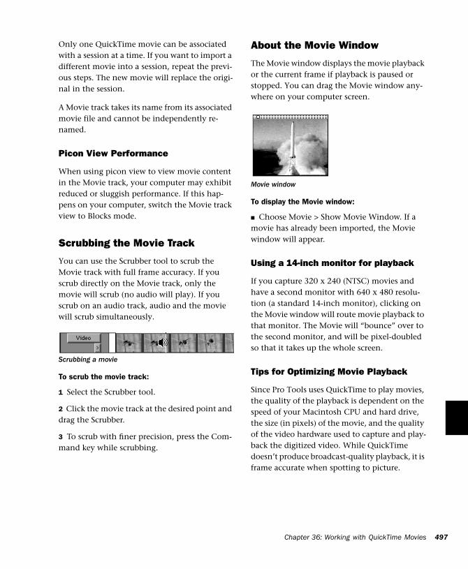
Only one QuickTime movie can be associated with a session at a time. If you want to import a different movie into a session, repeat the previ-ous steps. The new movie will replace the origi-nal in the session.
A Movie track takes its name from its associated movie file and cannot be independently re-named.
Picon View Performance
When using picon view to view movie content in the Movie track, your computer may exhibit reduced or sluggish performance. If this hap-pens on your computer, switch the Movie track view to Blocks mode.
Scrubbing the Movie Track
You can use the Scrubber tool to scrub the Movie track with full frame accuracy. If you scrub directly on the Movie track, only the movie will scrub (no audio will play). If you scrub on an audio track, audio and the movie will scrub simultaneously.
To scrub the movie track:
1 Select the Scrubber tool.
2 Click the movie track at the desired point and drag the Scrubber.
3 To scrub with finer precision, press the Com-mand key while scrubbing.
Scrubbing a movie
About the Movie Window
The Movie window displays the movie playback or the current frame if playback is paused or stopped. You can drag the Movie window any-where on your computer screen.
To display the Movie window:
■ Choose Movie > Show Movie Window. If a movie has already been imported, the Movie window will appear.
Using a 14-inch monitor for playback
If you capture 320 x 240 (NTSC) movies and have a second monitor with 640 x 480 resolu-tion (a standard 14-inch monitor), clicking on the Movie window will route movie playback to that monitor. The Movie will “bounce” over to the second monitor, and will be pixel-doubled so that it takes up the whole screen.
Tips for Optimizing Movie Playback
Since Pro Tools uses QuickTime to play movies, the quality of the playback is dependent on the speed of your Macintosh CPU and hard drive, the size (in pixels) of the movie, and the quality of the video hardware used to capture and play-back the digitized video. While QuickTime doesn’t produce broadcast-quality playback, it is frame accurate when spotting to picture.
Movie window
Chapter 36: Working with QuickTime Movies 497
498
On PCI-based computers, Pro Tools continu-ously re-syncs the movie. The movie resolves to the audio sample clock. This allows the movie to smoothly track the audio even when your sys-tem is varispeeded.
For more consistently smooth movie playback, here are some suggestions:
◆ Use a Digidesign-approved video capture and playback card for 25/30 frames-per-second full-screen movie playback.
◆ Display the movie on a separate monitor driven by a video capture and playback card.
◆ If you don’t have a video capture and play-back card, set the movie playback priority to Me-dium Priority Playback or High Priority Playback using one of these commands in Movie menu. This gives priority to movie playback, rather than other screen graphics tasks such as moving faders.
◆ Use the fastest CPU possible.
◆ Capture and play QuickTime video from a separate hard drive than your Pro Tools audio drives.
◆ Remove unneeded System Extensions and Control Panels.
◆ Disable AppleTalk and other background tasks on the CPU, such as File Sharing, screen savers, Calculate Folder Size and any fax or e-mail soft-ware.
◆ Disable the Automation Preference for Faders Move During Playback.
◆ Set No Auto Scrolling in Operations > Scroll Options.
◆ Reduce the size of the Edit window to the smallest possible size.
◆ Close unnecessary windows.
Pro Tools Reference Guide
◆ Reduce the overall length of the SCSI chain of your computer system for improved through-put.
◆ Reduce the pixel size of the movie (e.g. reduce it from 640 x 480 pixels to 320 x 240 pixels).
Setting the Movie Start Time: Movie OffsetWhen you import a movie into your session, the first frame of the movie defaults to the start time of the session. In some cases, however, you may need to offset the movie by some amount for-wards or backwards so that you can accurately spot audio to the movie.
Since a movie can be moved inside the Movie track, it is fairly easy to match these two times. In fact, you may not have to move the Movie track at all.
For finer adjustment of a movie’s start time, you can use the Set Movie Sync Offset command to offset the movie in 1/4-frame increments. This is more accurate than dragging the movie track, and is especially useful in cases where your movie track happens to begin with a partial frame.
To set the movie offset:
1 Double-check that the session’s SMPTE frame rate matches that of the movie.
2 Choose Movie > Set Movie Sync Offset, enter the desired offset value, and click OK.
3 Lock the movie in place by choosing Edit > Lock/Unlock Region.
The Movie Sync Offset is always defined in Feet.Frames, regardless of the session time display.
To spot the movie to a sync point:
1 Double-check that the session’s SMPTE frame rate matches that of the movie.
2 In the Edit window, enable Grid mode.
3 Set the session time display to SMPTE.
4 Set the Grid Value to Feet.Frames.
5 With the Selector, click in the Movie Track to place the cursor where you want to create a Sync Point. Often, the best spot will be the “2 beep” two seconds before the first action frame (the start of the video). You can use the plus and mi-nus keys on the alpha keyboard to nudge the cursor and the Movie one frame at a time.
6 Choose Edit > Identify Sync Point to place a Sync Point at the current cursor location.
7 Put Pro Tools into Spot mode by clicking the Spot button in the Edit window.
8 Click the Movie track with the Grabber. The Move Region To dialog appears.
9 Enter the time code number displayed in the window-burn of the frame you are spotting to (if the movie has a SMPTE time code window burned into it) and click OK to close the Move Region To dialog.
10 The movie’s sync point moves to the SMPTE location you entered.
Spotting Audio to a QuickTime MovieFor accurate spotting, Grid mode provides you with an effective tool for quick and accurate se-lection of waveforms, and alignment of regions in tracks. When Grid mode is enabled, the Selec-tor will snap to the current Grid Value, and re-gions selected with the Grabber and dragged to a track will also align up with the Grid Value.
Conforming Your Movie
Before you spot audio to a movie, you should conform the movie file so each frame starts and ends at valid frame boundaries.
For example, Adobe Premiere contains a Con-form Movie tool for destructively editing the lengths of each frame to the grid of the current frame rate. You should conform the movie to a frame rate that Pro Tools can work with (30 fps or 29.97 fps).
Consult your video capture software documen-tation for more information.
More Tips for Spotting Audio
◆ Specify your movie size up front. For purposes of spotting audio, 320 x 240 is usually adequate. If you are displaying the movie on a second monitor with 640 x 480 resolution, with pixel doubling, it will fill the screen.
◆ Try to work with a window burn in the movie, since it will help you spot material. You can pro-duce your own window burns for the capture us-ing Digidesign's Universal Slave Driver.
If your destination is a pulled-down Pro Tools session, the pull down affects QuickTime movie playback speed. Conform your movie to a 30 fps frame rate for use in a pulled-down session.
Chapter 36: Working with QuickTime Movies 499
500
◆ Use a continuous scrolling option. Pro Tools includes two scrolling options that are particu-larly useful in post-production: Continuous Scroll During Playback, and Continuous Scroll with Playhead. Enable either of these scrolling options by selecting them from the Operations > Scroll Options submenu. For more information, see Chapter 16, “Playing and Se-lecting Track Material.”.
Using Grid Mode to Spot and Nudge Regions with Frame Accuracy(TDM Systems Only)
Grid mode allows you to constrain the move-ment of regions so that they snap to SMPTE-based measurements (minutes, seconds, frames, or subframes).
To spot audio to a movie:
1 Click the Grid button at the upper left corner of the Edit window. This ensures that the audio will align to a frame boundary.
2 Set your Grid Value to Time Code using the pop-up menu.
3 Choose a desirable Grid unit setting. Note that you can set the grid units independently of the Main Time Scale.
4 Using the Selector, place the insertion cursor at the desired location in the movie. If you want, use the Nudge Value pop-up to set the nudge units to frames. You can then use the plus and minus keys on the alpha keyboard to nudge the insertion point frame by frame.
Pro Tools Reference Guide
5 While pressing the Control key, drag the de-sired region from the Regions List to the appro-priate track. Pro Tools will automatically spot the region to the same time location as the cur-sor.
Importing QuickTime AudioPro Tools allows you to import audio directly from a QuickTime movie. You can import audio from a movie currently loaded into a session, or from a different movie. The procedure is the same for both.
Sample Rate Conversion Quality
If you import QuickTime audio that was not originally recorded at the session’s sample rate, the sample rate is converted to match the audio to your session. Pro Tools allows you to choose the quality of the sample rate conversion via the Conversion Quality parameter in the Editing Preferences. The higher the quality of sample rate conversion that you choose, the longer it takes to perform the sample rate conversion.
The five conversion settings range from Low to Tweak Head. The Low setting provides results that are considerably better than the Macin-tosh’s built-in sample rate conversion. For most applications, the Better setting will yield excel-lent results.
To spot elements directly to locations in the movie, use the technique described above. In this scenario, Auto Spot mode is not recom-mended, since it uses incoming MTC for lo-cation information.
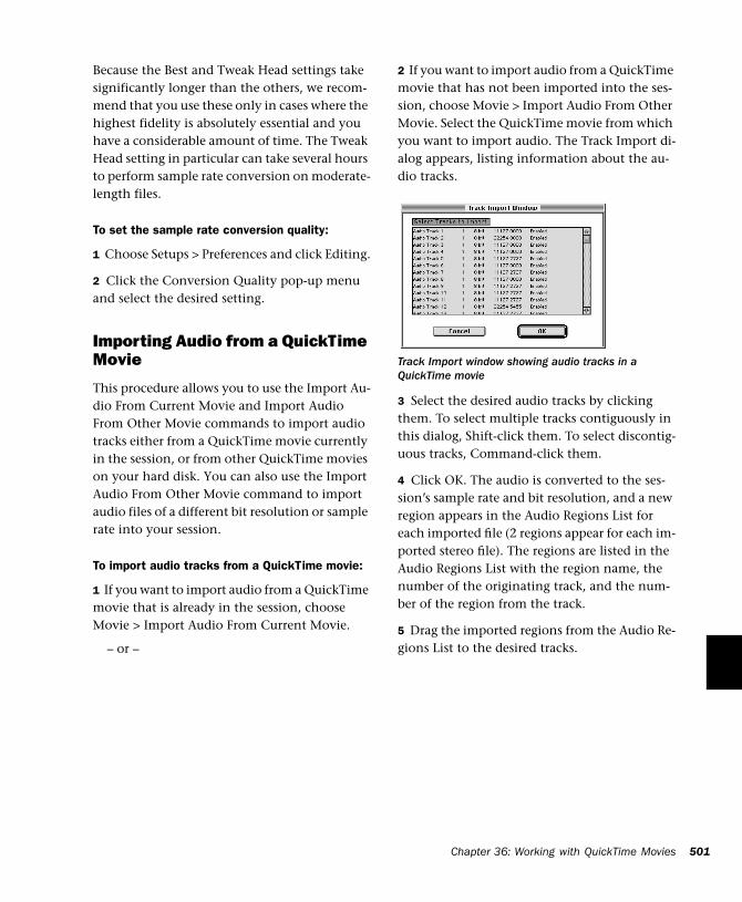
Because the Best and Tweak Head settings take significantly longer than the others, we recom-mend that you use these only in cases where the highest fidelity is absolutely essential and you have a considerable amount of time. The Tweak Head setting in particular can take several hours to perform sample rate conversion on moderate-length files.
To set the sample rate conversion quality:
1 Choose Setups > Preferences and click Editing.
2 Click the Conversion Quality pop-up menu and select the desired setting.
Importing Audio from a QuickTime Movie
This procedure allows you to use the Import Au-dio From Current Movie and Import Audio From Other Movie commands to import audio tracks either from a QuickTime movie currently in the session, or from other QuickTime movies on your hard disk. You can also use the Import Audio From Other Movie command to import audio files of a different bit resolution or sample rate into your session.
To import audio tracks from a QuickTime movie:
1 If you want to import audio from a QuickTime movie that is already in the session, choose Movie > Import Audio From Current Movie.
– or –
2 If you want to import audio from a QuickTime movie that has not been imported into the ses-sion, choose Movie > Import Audio From Other Movie. Select the QuickTime movie from which you want to import audio. The Track Import di-alog appears, listing information about the au-dio tracks.
3 Select the desired audio tracks by clicking them. To select multiple tracks contiguously in this dialog, Shift-click them. To select discontig-uous tracks, Command-click them.
4 Click OK. The audio is converted to the ses-sion’s sample rate and bit resolution, and a new region appears in the Audio Regions List for each imported file (2 regions appear for each im-ported stereo file). The regions are listed in the Audio Regions List with the region name, the number of the originating track, and the num-ber of the region from the track.
5 Drag the imported regions from the Audio Re-gions List to the desired tracks.
Track Import window showing audio tracks in a QuickTime movie
Chapter 36: Working with QuickTime Movies 501
502
Bouncing to a new MovieWhen you have finished your final mix and syn-chronized your audio events to the movie, you can use the Pro Tools Bounce to Movie com-mand to compile a new QuickTime movie with the bounced audio embedded in the QuickTime movie file as the soundtrack. As a QuickTime file, the new movie is supported by all software applications that support QuickTime video.
To create a new QuickTime movie with bounced audio embedded as the soundtrack:
1 Adjust track output levels and finalize your mix. Any inserts and effects settings that are ac-tive on tracks will be permanently written to the bounced tracks. If you don’t want to apply a plug-in to the bounce, click the Bypass button in the Plug-In window.
2 Make sure that all of the tracks you want to in-clude in the bounce are audible (not muted).
3 Assign the output of each of the tracks you want to include in the bounce to the same out-put pair.
4 If you want to bounce the entire session, press the Return to Zero button on the Transport to go to the beginning of the session. The new movie file will include all the video and audio material in the session, even if the duration of the video material is longer than the audio or vice versa. If you only want to bounce a portion of a session, open the Edit window and select the section that you want to include in the bounce.
5 Choose Movie > Bounce to Movie.
6 Select the file format for the movie audio. Choose Mix-to-Mono to combine the left and right channel output of the session to a mono movie soundtrack. Choose Stereo to retain the stereo mix of the session for the movie audio.
Pro Tools Reference Guide
7 Select the resolution for the movie audio. Red Book audio CDs are always 16-bit, while many multimedia presentations and CD-ROMs use 8-bit resolution. You cannot create a QuickTime movie with 24-bit audio; audio from 24-bit ses-sions is converted to 16-bit or 8-bit audio, de-pending on what you choose.
8 If you intend to convert the session to 8-bit resolution for use in multimedia, use the Squeezer option (click the Convert after Bounce option, then the Settings button to access this feature) to improve the fidelity of the converted 8-bit audio. This option uses a proprietary DSP algorithm that preprocesses the audio using compression, limiting and gating before con-verting to 8-bit resolution. This option is recom-mend for optimal results.
9 Select the Sample Rate for the movie audio (click the Convert after Bounce option, then the Settings button to access this parameter). The default audio sample rate is 44100 (44.1kHz), which is the standard sample rate for audio CDs. Multimedia presentations and CD-ROMs may use a sample rate of 11025 (11.025kHz) or 22050 (22.050kHz).
10 Click Bounce, name the new movie, and choose where to save it.
11 The audio tracks are converted to the se-lected sample rate and bit resolution, and a new flattened movie is created incorporating the au-dio. You can open and play the flattened movie in any software application that supports Quick-Time.
Pro Tools sample rate and bit resolution conversions use large amounts of processing power. You can save time by selecting a lower sample rate conversion quality in the Editing Preferences.

503
Part IX: Pro Tools Menus

504
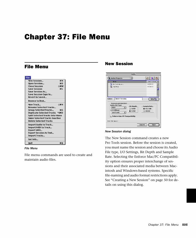
Chapter 37: File Menu
File Menu
File menu commands are used to create and maintain audio files.
File Menu
New Session
The New Session command creates a new Pro Tools session. Before the session is created, you must name the session and choose its Audio File type, I/O Settings, Bit Depth and Sample Rate. Selecting the Enforce Mac/PC Compatibil-ity option ensures proper interchange of ses-sions and their associated media between Mac-intosh and Windows-based systems. Specific file-naming and audio format restrictions apply. See “Creating a New Session” on page 50 for de-tails on using this dialog.
New Session dialog
Chapter 37: File Menu 505
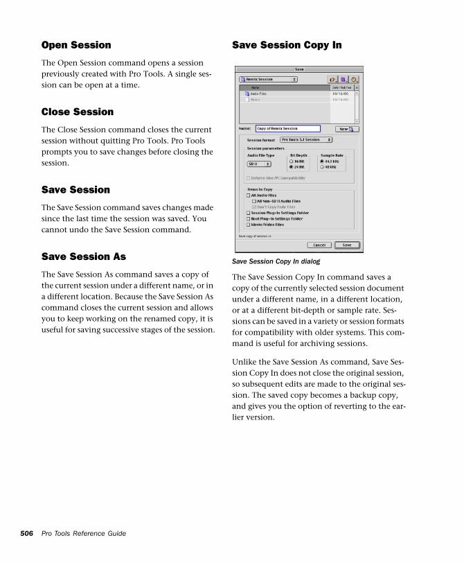
506
Open Session
The Open Session command opens a session previously created with Pro Tools. A single ses-sion can be open at a time.
Close Session
The Close Session command closes the current session without quitting Pro Tools. Pro Tools prompts you to save changes before closing the session.
Save Session
The Save Session command saves changes made since the last time the session was saved. You cannot undo the Save Session command.
Save Session As
The Save Session As command saves a copy of the current session under a different name, or in a different location. Because the Save Session As command closes the current session and allows you to keep working on the renamed copy, it is useful for saving successive stages of the session.
Pro Tools Reference Guide
Save Session Copy In
The Save Session Copy In command saves a copy of the currently selected session document under a different name, in a different location, or at a different bit-depth or sample rate. Ses-sions can be saved in a variety or session formats for compatibility with older systems. This com-mand is useful for archiving sessions.
Unlike the Save Session As command, Save Ses-sion Copy In does not close the original session, so subsequent edits are made to the original ses-sion. The saved copy becomes a backup copy, and gives you the option of reverting to the ear-lier version.
Save Session Copy In dialog
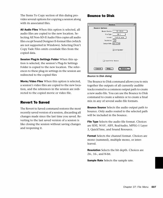
The Items To Copy section of this dialog pro-vides several options for copying a session along with its associated files.
All Audio Files When this option is selected, all audio files are copied to the new location. Se-lecting All Non-SD-II Audio Files copies all audio files except Sound Designer II-format files (which are not supported in Windows). Selecting Don’t Copy Fade Files omits crossfade files from the copied data.
Session Plug-In Settings Folder When this op-tion is selected, the session’s Plug-In Settings Folder is copied to the new location. The refer-ences to these plug-in settings in the session are redirected to the copied files
Movie/Video Files When this option is selected, a session’s video files are copied to the new loca-tion, and the references in the session are redi-rected to the copied movie or video file.
Revert To Saved
The Revert to Saved command restores the most recently saved version of a session, discarding all changes made since the last time you saved. Re-verting to the last saved version of a session is like closing the session without saving changes and reopening it.
Bounce to Disk
The Bounce to Disk command allows you to mix together the outputs of all currently audible tracks routed to a common output path to create a new audio file. You can use the Bounce to Disk command to create a submix or to create a final mix in any of several audio file formats.
Bounce Source Selects the audio output path to bounce. Only audio routed to the selected path will be included in the bounce.
File Type Selects the audio file format. Choices are SDII, WAV, AIFF, RealAudio, MPEG-1 Layer 3, QuickTime, and Sound Resource.
Format Selects the channel format. Choices are mono (summed), multiple mono, or inter-leaved.
Resolution Selects the bit depth. Choices are 24-, 16-, and 8-bit.
Sample Rate Selects the sample rate.
Bounce to Disk dialog
Chapter 37: File Menu 507
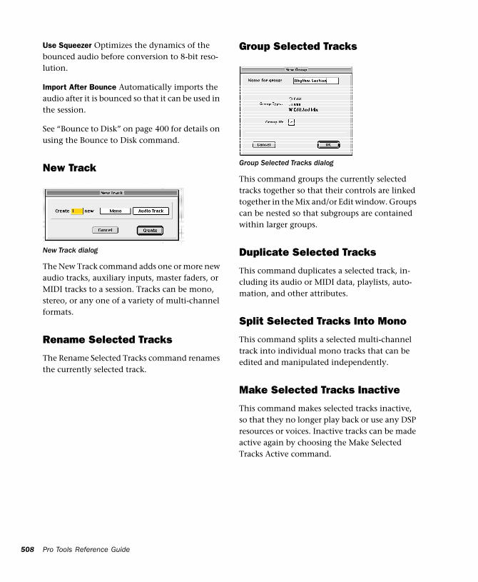
508
Use Squeezer Optimizes the dynamics of the bounced audio before conversion to 8-bit reso-lution.
Import After Bounce Automatically imports the audio after it is bounced so that it can be used in the session.
See “Bounce to Disk” on page 400 for details on using the Bounce to Disk command.
New Track
The New Track command adds one or more new audio tracks, auxiliary inputs, master faders, or MIDI tracks to a session. Tracks can be mono, stereo, or any one of a variety of multi-channel formats.
Rename Selected Tracks
The Rename Selected Tracks command renames the currently selected track.
New Track dialog
Pro Tools Reference Guide
Group Selected Tracks
This command groups the currently selected tracks together so that their controls are linked together in the Mix and/or Edit window. Groups can be nested so that subgroups are contained within larger groups.
Duplicate Selected Tracks
This command duplicates a selected track, in-cluding its audio or MIDI data, playlists, auto-mation, and other attributes.
Split Selected Tracks Into Mono
This command splits a selected multi-channel track into individual mono tracks that can be edited and manipulated independently.
Make Selected Tracks Inactive
This command makes selected tracks inactive, so that they no longer play back or use any DSP resources or voices. Inactive tracks can be made active again by choosing the Make Selected Tracks Active command.
Group Selected Tracks dialog
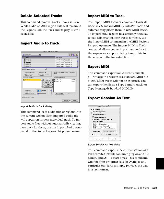
Delete Selected Tracks
This command removes tracks from a session. While audio or MIDI region data will remain in the Regions List, the track and its playlists will be deleted.
Import Audio to Track
This command loads audio files or regions into the current session. Each imported audio file will appear on its own individual track. To im-port audio files without automatically creating new track for them, use the Import Audio com-mand in the Audio Regions List pop-up menu.
Import Audio to Track dialog
Import MIDI to Track
The Import MIDI to Track command loads all tracks in a Standard MIDI file into Pro Tools and automatically places them in new MIDI tracks. To import MIDI regions to a session without au-tomatically creating new tracks for them, use the Import MIDI command in the MIDI Regions List pop-up menu. The Import MIDI to Track command allows you to import tempo data in the sequence or apply existing tempo data in the session to the imported file.
Export MIDI
This command exports all currently audible MIDI tracks in a session as a standard MIDI file. Muted MIDI tracks will not be exported. You can export the file as a Type 1 (multi-track) or Type 0 (merged) Standard MIDI file.
Export Session As Text
This command exports the current session as a tab-delimited text file containing region and file names, and SMPTE start times. This command will not print or format session events to any particular standard; it simply provides the data in a text format.
Export Session As Text dialog
Chapter 37: File Menu 509
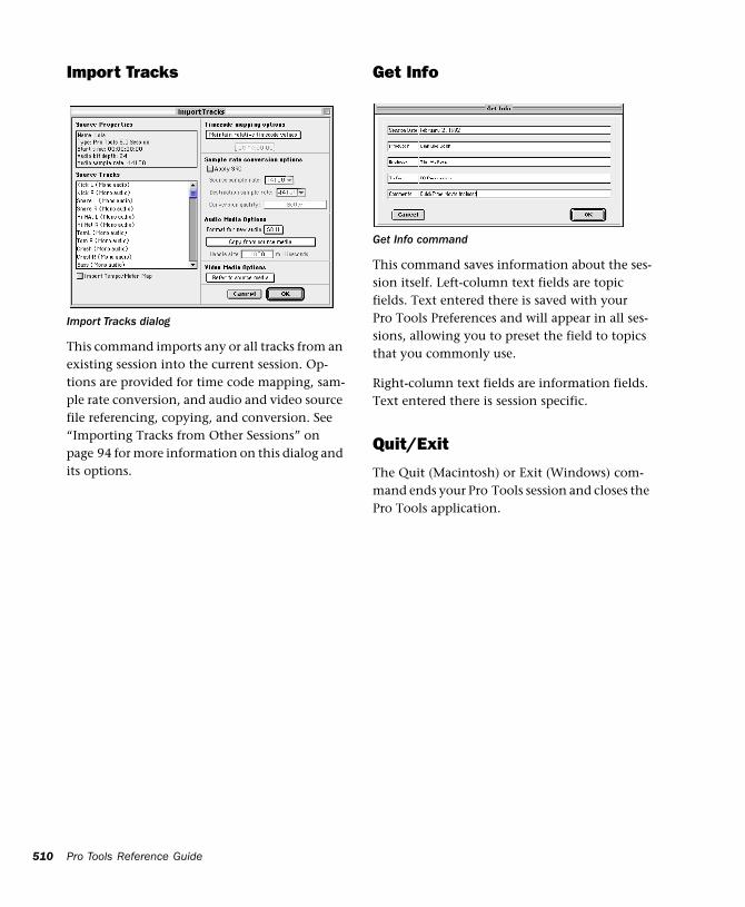
510
Import Tracks
This command imports any or all tracks from an existing session into the current session. Op-tions are provided for time code mapping, sam-ple rate conversion, and audio and video source file referencing, copying, and conversion. See “Importing Tracks from Other Sessions” on page 94 for more information on this dialog and its options.
Import Tracks dialog
Pro Tools Reference Guide
Get Info
This command saves information about the ses-sion itself. Left-column text fields are topic fields. Text entered there is saved with your Pro Tools Preferences and will appear in all ses-sions, allowing you to preset the field to topics that you commonly use.
Right-column text fields are information fields. Text entered there is session specific.
Quit/Exit
The Quit (Macintosh) or Exit (Windows) com-mand ends your Pro Tools session and closes the Pro Tools application.
Get Info command
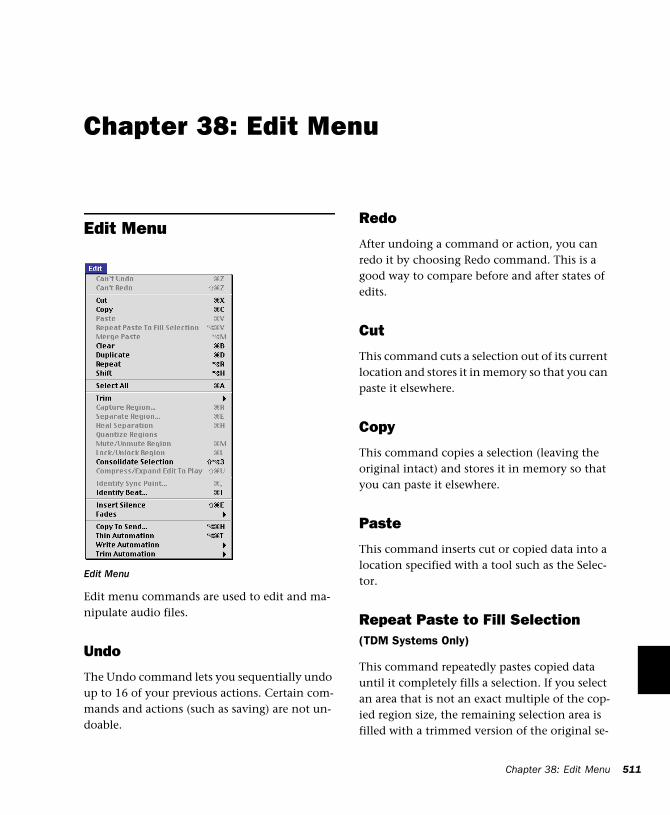
Chapter 38: Edit Menu
Edit Menu
Edit menu commands are used to edit and ma-nipulate audio files.
Undo
The Undo command lets you sequentially undo up to 16 of your previous actions. Certain com-mands and actions (such as saving) are not un-doable.
Edit Menu
Redo
After undoing a command or action, you can redo it by choosing Redo command. This is a good way to compare before and after states of edits.
Cut
This command cuts a selection out of its current location and stores it in memory so that you can paste it elsewhere.
Copy
This command copies a selection (leaving the original intact) and stores it in memory so that you can paste it elsewhere.
Paste
This command inserts cut or copied data into a location specified with a tool such as the Selec-tor.
Repeat Paste to Fill Selection(TDM Systems Only)
This command repeatedly pastes copied data until it completely fills a selection. If you select an area that is not an exact multiple of the cop-ied region size, the remaining selection area is filled with a trimmed version of the original se-
Chapter 38: Edit Menu 511
512
lection. This allows you to easily create drum loops and other highly repetitive effects. Before the data is pasted, Pro Tools prompts you to specify a crossfade to smooth transitions be-tween regions.
Merge Paste
This command pastes MIDI data into a track without replacing existing data by merging the pasted data with the existing data. This is useful for consolidating MIDI data from several tracks into a single MIDI track.
Clear
This command removes a selection in the Edit window.
Duplicate
This command copies a selection and places it immediately after the end of that selection in a track.
Repeat
This command is similar to Duplicate, but al-lows you to specify the number of times the se-lected material is duplicated. To use this com-mand, select the material you want to repeat, choose Repeat, then enter the number of repeti-tions.
Shift
This command moves track material earlier or later in time by a specified amount. To use this command, select the material you want to move, choose Shift, then enter the desired direc-tion and time value.
Pro Tools Reference Guide
Select All
This command selects all audio and MIDI data in one or more tracks.
◆ To select all regions in a single track, select a portion of the track, or click the Selector any-where in a track and choose Select All.
◆ To select all regions on multiple tracks, Shift-click a region on each track with the Selector or Grabber and choose Select All.
◆ To select all regions on all tracks, Select the “All” Edit Group in the Groups list, click the Se-lector anywhere in a track and choose Select All.
Trim
This command removes audio before and after a selection, leaving only the selection. This pro-vides a convenient means of quickly removing all data within a region except the current selec-tion.
Capture Region
This command defines a selection as a new re-gion and adds it to the Regions List. From there the new region can be dragged into a track. You cannot capture selections across multiple re-gions unless the data is contiguous material from the same file.
Separate Region
This command defines a selection as a new re-gion (or the current insertion point as a region split point), and in the process, separates it from adjacent data in the track where it was created. By separating a region you will also create by-product regions from data on either side of the separation.
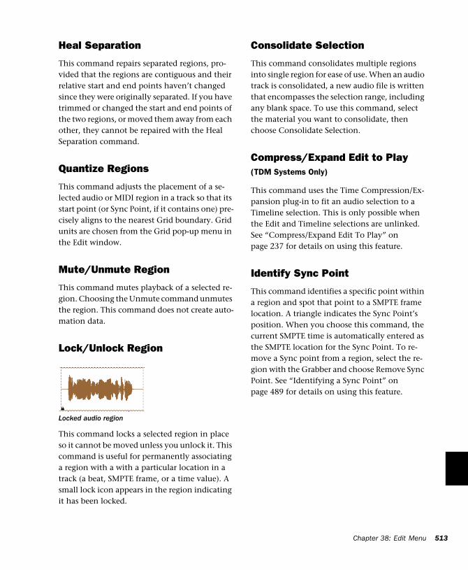
Heal Separation
This command repairs separated regions, pro-vided that the regions are contiguous and their relative start and end points haven’t changed since they were originally separated. If you have trimmed or changed the start and end points of the two regions, or moved them away from each other, they cannot be repaired with the Heal Separation command.
Quantize Regions
This command adjusts the placement of a se-lected audio or MIDI region in a track so that its start point (or Sync Point, if it contains one) pre-cisely aligns to the nearest Grid boundary. Grid units are chosen from the Grid pop-up menu in the Edit window.
Mute/Unmute Region
This command mutes playback of a selected re-gion. Choosing the Unmute command unmutes the region. This command does not create auto-mation data.
Lock/Unlock Region
This command locks a selected region in place so it cannot be moved unless you unlock it. This command is useful for permanently associating a region with a with a particular location in a track (a beat, SMPTE frame, or a time value). A small lock icon appears in the region indicating it has been locked.
Locked audio region
Consolidate Selection
This command consolidates multiple regions into single region for ease of use. When an audio track is consolidated, a new audio file is written that encompasses the selection range, including any blank space. To use this command, select the material you want to consolidate, then choose Consolidate Selection.
Compress/Expand Edit to Play(TDM Systems Only)
This command uses the Time Compression/Ex-pansion plug-in to fit an audio selection to a Timeline selection. This is only possible when the Edit and Timeline selections are unlinked. See “Compress/Expand Edit To Play” on page 237 for details on using this feature.
Identify Sync Point
This command identifies a specific point within a region and spot that point to a SMPTE frame location. A triangle indicates the Sync Point’s position. When you choose this command, the current SMPTE time is automatically entered as the SMPTE location for the Sync Point. To re-move a Sync point from a region, select the re-gion with the Grabber and choose Remove Sync Point. See “Identifying a Sync Point” on page 489 for details on using this feature.
Chapter 38: Edit Menu 513
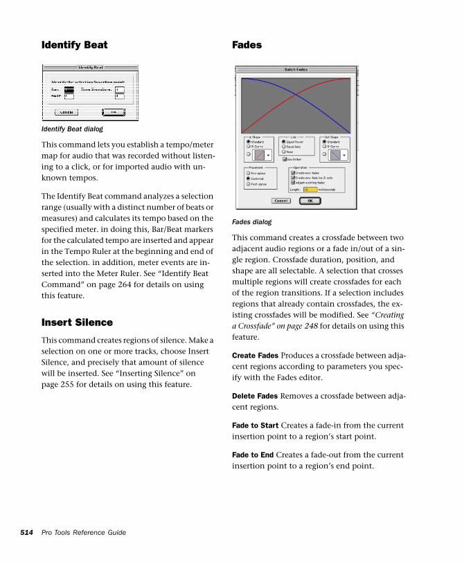
514
Identify Beat
This command lets you establish a tempo/meter map for audio that was recorded without listen-ing to a click, or for imported audio with un-known tempos.
The Identify Beat command analyzes a selection range (usually with a distinct number of beats or measures) and calculates its tempo based on the specified meter. in doing this, Bar/Beat markers for the calculated tempo are inserted and appear in the Tempo Ruler at the beginning and end of the selection. in addition, meter events are in-serted into the Meter Ruler. See “Identify Beat Command” on page 264 for details on using this feature.
Insert Silence
This command creates regions of silence. Make a selection on one or more tracks, choose Insert Silence, and precisely that amount of silence will be inserted. See “Inserting Silence” on page 255 for details on using this feature.
Identify Beat dialog
Pro Tools Reference Guide
Fades
This command creates a crossfade between two adjacent audio regions or a fade in/out of a sin-gle region. Crossfade duration, position, and shape are all selectable. A selection that crosses multiple regions will create crossfades for each of the region transitions. If a selection includes regions that already contain crossfades, the ex-isting crossfades will be modified. See “Creating a Crossfade” on page 248 for details on using this feature.
Create Fades Produces a crossfade between adja-cent regions according to parameters you spec-ify with the Fades editor.
Delete Fades Removes a crossfade between adja-cent regions.
Fade to Start Creates a fade-in from the current insertion point to a region’s start point.
Fade to End Creates a fade-out from the current insertion point to a region’s end point.
Fades dialog
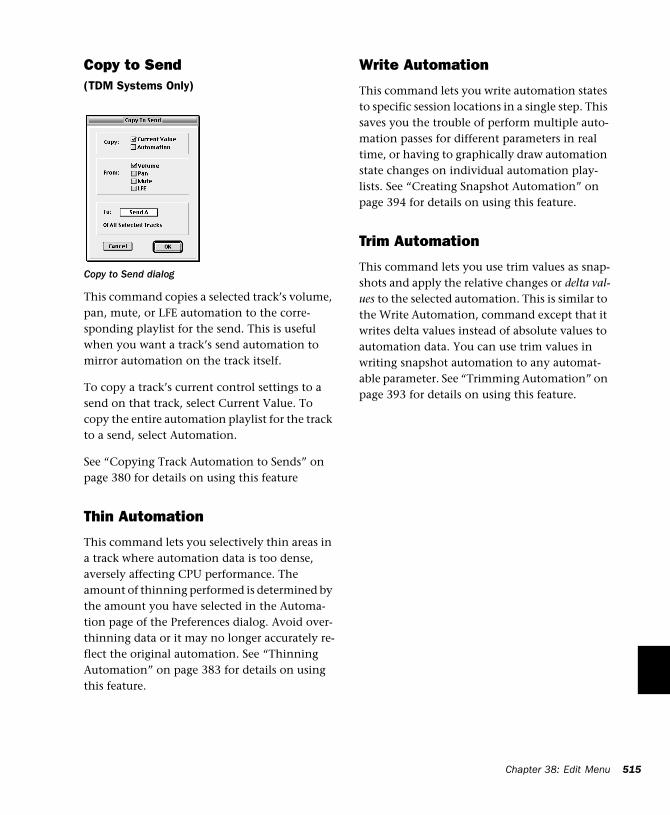
Copy to Send(TDM Systems Only)
This command copies a selected track’s volume, pan, mute, or LFE automation to the corre-sponding playlist for the send. This is useful when you want a track’s send automation to mirror automation on the track itself.
To copy a track’s current control settings to a send on that track, select Current Value. To copy the entire automation playlist for the track to a send, select Automation.
See “Copying Track Automation to Sends” on page 380 for details on using this feature
Thin Automation
This command lets you selectively thin areas in a track where automation data is too dense, aversely affecting CPU performance. The amount of thinning performed is determined by the amount you have selected in the Automa-tion page of the Preferences dialog. Avoid over-thinning data or it may no longer accurately re-flect the original automation. See “Thinning Automation” on page 383 for details on using this feature.
Copy to Send dialog
Write Automation
This command lets you write automation states to specific session locations in a single step. This saves you the trouble of perform multiple auto-mation passes for different parameters in real time, or having to graphically draw automation state changes on individual automation play-lists. See “Creating Snapshot Automation” on page 394 for details on using this feature.
Trim Automation
This command lets you use trim values as snap-shots and apply the relative changes or delta val-ues to the selected automation. This is similar to the Write Automation, command except that it writes delta values instead of absolute values to automation data. You can use trim values in writing snapshot automation to any automat-able parameter. See “Trimming Automation” on page 393 for details on using this feature.
Chapter 38: Edit Menu 515

516
Pro Tools Reference Guide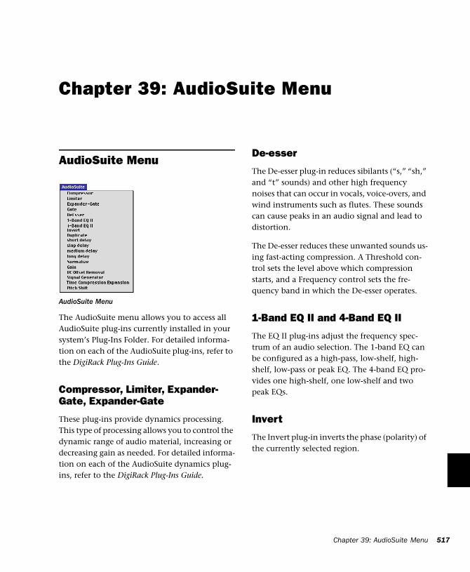
Chapter 39: AudioSuite Menu
AudioSuite Menu
The AudioSuite menu allows you to access all AudioSuite plug-ins currently installed in your system’s Plug-Ins Folder. For detailed informa-tion on each of the AudioSuite plug-ins, refer to the DigiRack Plug-Ins Guide.
Compressor, Limiter, Expander-Gate, Expander-Gate
These plug-ins provide dynamics processing. This type of processing allows you to control the dynamic range of audio material, increasing or decreasing gain as needed. For detailed informa-tion on each of the AudioSuite dynamics plug-ins, refer to the DigiRack Plug-Ins Guide.
AudioSuite Menu
De-esser
The De-esser plug-in reduces sibilants (“s,” “sh,” and “t” sounds) and other high frequency noises that can occur in vocals, voice-overs, and wind instruments such as flutes. These sounds can cause peaks in an audio signal and lead to distortion.
The De-esser reduces these unwanted sounds us-ing fast-acting compression. A Threshold con-trol sets the level above which compression starts, and a Frequency control sets the fre-quency band in which the De-esser operates.
1-Band EQ II and 4-Band EQ II
The EQ II plug-ins adjust the frequency spec-trum of an audio selection. The 1-band EQ can be configured as a high-pass, low-shelf, high-shelf, low-pass or peak EQ. The 4-band EQ pro-vides one high-shelf, one low-shelf and two peak EQs.
Invert
The Invert plug-in inverts the phase (polarity) of the currently selected region.
Chapter 39: AudioSuite Menu 517
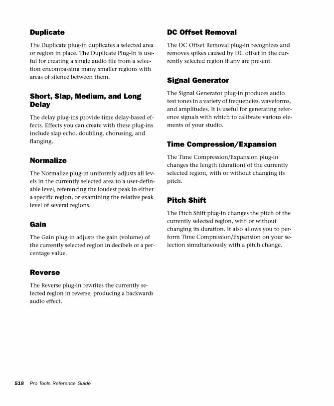
518
Duplicate
The Duplicate plug-in duplicates a selected area or region in place. The Duplicate Plug-In is use-ful for creating a single audio file from a selec-tion encompassing many smaller regions with areas of silence between them.
Short, Slap, Medium, and Long Delay
The delay plug-ins provide time delay-based ef-fects. Effects you can create with these plug-ins include slap echo, doubling, chorusing, and flanging.
Normalize
The Normalize plug-in uniformly adjusts all lev-els in the currently selected area to a user-defin-able level, referencing the loudest peak in either a specific region, or examining the relative peak level of several regions.
Gain
The Gain plug-in adjusts the gain (volume) of the currently selected region in decibels or a per-centage value.
Reverse
The Reverse plug-in rewrites the currently se-lected region in reverse, producing a backwards audio effect.
Pro Tools Reference Guide
DC Offset Removal
The DC Offset Removal plug-in recognizes and removes spikes caused by DC offset in the cur-rently selected region if any are present.
Signal Generator
The Signal Generator plug-in produces audio test tones in a variety of frequencies, waveforms, and amplitudes. It is useful for generating refer-ence signals with which to calibrate various ele-ments of your studio.
Time Compression/Expansion
The Time Compression/Expansion plug-in changes the length (duration) of the currently selected region, with or without changing its pitch.
Pitch Shift
The Pitch Shift plug-in changes the pitch of the currently selected region, with or without changing its duration. It also allows you to per-form Time Compression/Expansion on your se-lection simultaneously with a pitch change.
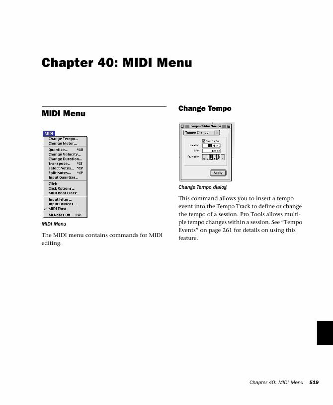
Chapter 40: MIDI Menu
MIDI Menu
The MIDI menu contains commands for MIDI editing.
MIDI Menu
Change Tempo
This command allows you to insert a tempo event into the Tempo Track to define or change the tempo of a session. Pro Tools allows multi-ple tempo changes within a session. See “Tempo Events” on page 261 for details on using this feature.
Change Tempo dialog
Chapter 40: MIDI Menu 519
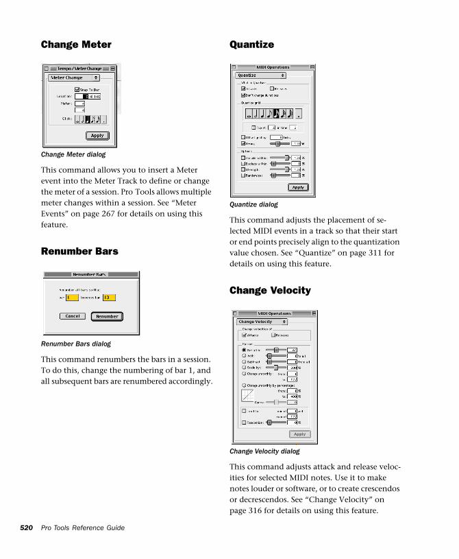
520
Change Meter
This command allows you to insert a Meter event into the Meter Track to define or change the meter of a session. Pro Tools allows multiple meter changes within a session. See “Meter Events” on page 267 for details on using this feature.
Renumber Bars
This command renumbers the bars in a session. To do this, change the numbering of bar 1, and all subsequent bars are renumbered accordingly.
Change Meter dialog
Renumber Bars dialog
Pro Tools Reference Guide
Quantize
This command adjusts the placement of se-lected MIDI events in a track so that their start or end points precisely align to the quantization value chosen. See “Quantize” on page 311 for details on using this feature.
Change Velocity
This command adjusts attack and release veloc-ities for selected MIDI notes. Use it to make notes louder or software, or to create crescendos or decrescendos. See “Change Velocity” on page 316 for details on using this feature.
Quantize dialog
Change Velocity dialog
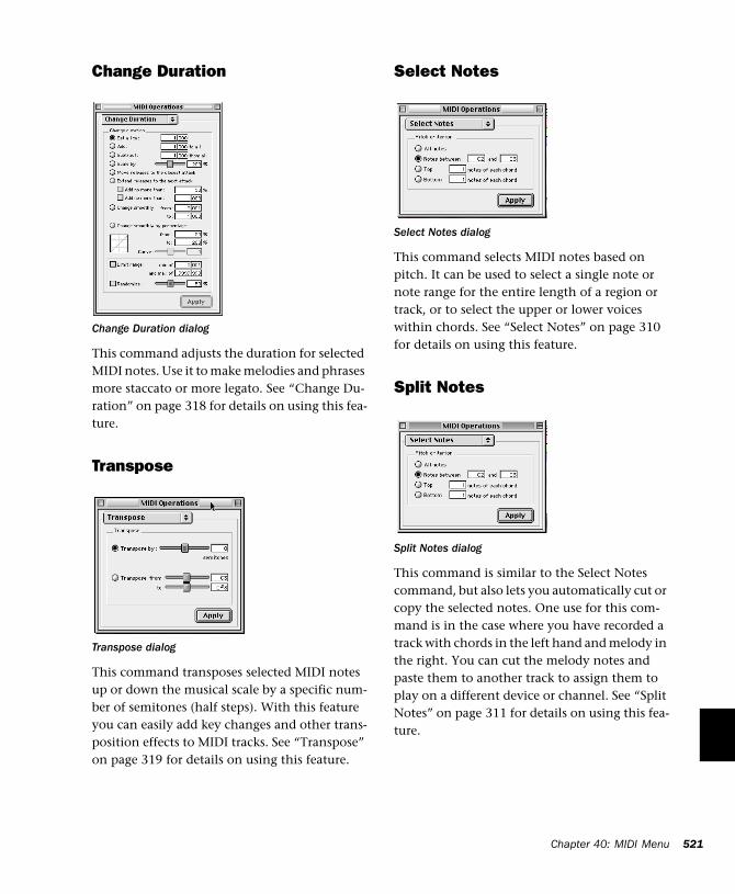
Change Duration
This command adjusts the duration for selected MIDI notes. Use it to make melodies and phrases more staccato or more legato. See “Change Du-ration” on page 318 for details on using this fea-ture.
Transpose
This command transposes selected MIDI notes up or down the musical scale by a specific num-ber of semitones (half steps). With this feature you can easily add key changes and other trans-position effects to MIDI tracks. See “Transpose” on page 319 for details on using this feature.
Change Duration dialog
Transpose dialog
Select Notes
This command selects MIDI notes based on pitch. It can be used to select a single note or note range for the entire length of a region or track, or to select the upper or lower voices within chords. See “Select Notes” on page 310 for details on using this feature.
Split Notes
This command is similar to the Select Notes command, but also lets you automatically cut or copy the selected notes. One use for this com-mand is in the case where you have recorded a track with chords in the left hand and melody in the right. You can cut the melody notes and paste them to another track to assign them to play on a different device or channel. See “Split Notes” on page 311 for details on using this fea-ture.
Select Notes dialog
Split Notes dialog
Chapter 40: MIDI Menu 521
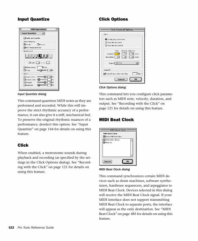
522
Input Quantize
This command quantizes MIDI notes as they are performed and recorded. While this will im-prove the strict rhythmic accuracy of a perfor-mance, it can also give it a stiff, mechanical feel. To preserve the original rhythmic nuances of a performance, deselect this option. See “Input Quantize” on page 144 for details on using this feature.
Click
When enabled, a metronome sounds during playback and recording (as specified by the set-tings in the Click Options dialog). See “Record-ing with the Click” on page 121 for details on using this feature.
Input Quantize dialog
Pro Tools Reference Guide
Click Options
This command lets you configure click parame-ters such as MIDI note, velocity, duration, and output. See “Recording with the Click” on page 121 for details on using this feature.
MIDI Beat Clock
This command synchronizes certain MIDI de-vices such as drum machines, software synthe-sizers, hardware sequencers, and arpeggiator to MIDI Beat Clock. Devices selected in this dialog will receive the MIDI Beat Clock signal. If your MIDI interface does not support transmitting MIDI Beat Clock to separate ports, the interface will appear as the only destination. See “MIDI Beat Clock” on page 485 for details on using this feature.
Click Options dialog
MIDI Beat Clock dialog
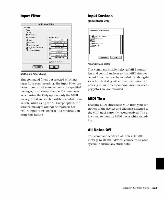
Input Filter
This command filters out selected MIDI mes-sages from your recording. The Input Filter can be set to record all messages, only the specified messages, or all except the specified messages. When using the Only option, only the MIDI messages that are selected will be recorded. Con-versely, when using the All Except option, the selected messages will not be recorded. See “MIDI Input Filter” on page 143 for details on using this feature.
MIDI Input Filter dialog
Input Devices(Macintosh Only)
This command enables selected MIDI control-lers and control surfaces so that MIDI data re-ceived from them can be recorded. Disabling de-vices in this dialog will ensure that unwanted notes (such as those from drum machines or ar-peggiator) are not recorded.
MIDI Thru
Enabling MIDI Thru routes MIDI from your con-trollers to the devices and channels assigned to the MIDI track currently record-enabled. This al-lows you to monitor MIDI tracks while record-ing.
All Notes Off
This command sends an All Notes Off MIDI message to all MIDI devices connected to your system to silence any stuck notes.
Input Devices dialog
Chapter 40: MIDI Menu 523

524
Pro Tools Reference Guide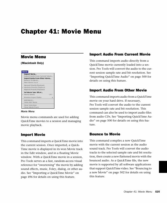
Chapter 41: Movie Menu
Movie Menu(Macintosh Only)
Movie menu commands are used for adding QuickTime movies to a session and managing movie playback.
Import Movie
This command imports a QuickTime movie into the current session. Once imported, a Quick-Time movie is displayed in its won Movie track in the Edit window, and in a floating Movie window. With a QuickTime movie in a session, Pro Tools serves as a fast, random-access visual reference for “sweetening” the movie by adding sound effects, music, Foley, dialog, or other au-dio. See “Importing a QuickTime Movie” on page 496 for details on using this feature.
Movie Menu
Import Audio From Current Movie
This command imports audio directly from a QuickTime movie currently loaded into a ses-sion. Pro Tools will convert the audio to the cur-rent session sample rate and bit resolution. See “Importing QuickTime Audio” on page 500 for details on using this feature.
Import Audio From Other Movie
This command imports audio from a QuickTime movie on your hard drive. If necessary, Pro Tools will convert the audio to the current session sample rate and bit resolution. This command can also be used to import audio files from audio CDs. See “Importing QuickTime Au-dio” on page 500 for details on using this fea-ture.
Bounce to Movie
This command compiles a new QuickTime movie with the current session as the audio sound track. Pro Tools will convert the audio tracks to the selected sample rate and bit resolu-tion, then create a new flattened movie with the bounced audio. As a QuickTime file, the new movie is supported by all software applications that support QuickTime video. See “Bouncing to a new Movie” on page 502 for details on using this feature.
Chapter 41: Movie Menu 525
526
New Movie Track
With the Pro Tools AVoption installed, this command creates a new empty movie track into which you can record or import video.
Normal Priority Playback
This is the default setting for QuickTime movie playback. It gives no extra priority to movie playback over other screen update tasks such as metering, moving faders, and so on. In most cases you should use this setting. If, however, you are running QuickTime movies without a video capture card, you may need to use the Me-dium or High Priority Playback setting.
Medium Priority Playback
This command gives QuickTime movie play-back a higher priority relative to other Pro Tools screen update tasks. This yields better movie playback performance if you are running Quick-Time movies without a video capture card.
Highest Priority Playback
This command gives QuickTime movie play-back highest priority. In this mode, Pro Tools disables screen activity such as metering during movie playback. This yields the highest movie playback performance if you are running Quick-Time movies without a video capture card.
Pro Tools Reference Guide
Set Movie Sync Offset
When you import a QuickTime movie into a ses-sion, by default, the first frame of the movie is set to the start time of the session. In some cases, you may need to offset the movie earlier or later so you can accurately spot audio to it. The Set Movie Sync Offset command allows you to set this offset in 1/4-frame increments. This is more accurate than dragging the movie track, and is especially useful in cases where a movie track begins with a partial frame.
Movie Online
This command enables and disables movie play-back. You may want to do this to have the Movie frozen at a particular point in time rela-tive to Pro Tools playback, or to give highest screen update priority to other Pro Tools tasks such as metering, moving faders, and so on.
Window Aspect Ratio
With the Pro Tools AVoption is installed, this command lets you to change the dimensions or aspect ratio of the Movie window.
Add Movie
This command adds additional movie clips to the Movie Track. You will be prompted to spot the clip to a SMPTE location. If the clip is spot-ted to a location that already contains a movie clip, the first clip will be truncated.
Undo Add Movie
This command undoes the Add Movie com-mand and other Movie Track-related editing functions such as moving, copying, or clearing clips. These actions cannot be undone by choos-ing the standard Undo command from the Edit menu.
Clear Selection
This command clears a selection in the Movie Track. This allows simple editing of movie clip content.
Clear Movie Track
This command clears the entire Movie Track.
Chapter 41: Movie Menu 527

528
Pro Tools Reference Guide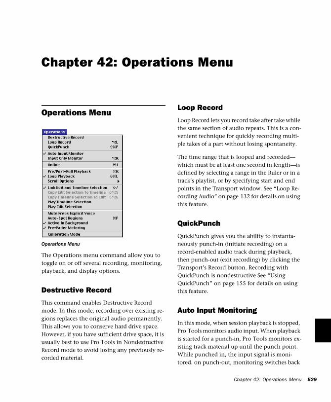
Chapter 42: Operations Menu
Operations Menu
The Operations menu command allow you to toggle on or off several recording, monitoring, playback, and display options.
Destructive Record
This command enables Destructive Record mode. In this mode, recording over existing re-gions replaces the original audio permanently. This allows you to conserve hard drive space. However, if you have sufficient drive space, it is usually best to use Pro Tools in Nondestructive Record mode to avoid losing any previously re-corded material.
Operations Menu
Loop Record
Loop Record lets you record take after take while the same section of audio repeats. This is a con-venient technique for quickly recording multi-ple takes of a part without losing spontaneity.
The time range that is looped and recorded—which must be at least one second in length—is defined by selecting a range in the Ruler or in a track’s playlist, or by specifying start and end points in the Transport window. See “Loop Re-cording Audio” on page 132 for details on using this feature.
QuickPunch
QuickPunch gives you the ability to instanta-neously punch-in (initiate recording) on a record-enabled audio track during playback, then punch-out (exit recording) by clicking the Transport’s Record button. Recording with QuickPunch is nondestructive See “Using QuickPunch” on page 155 for details on using this feature.
Auto Input Monitoring
In this mode, when session playback is stopped, Pro Tools monitors audio input. When playback is started for a punch-in, Pro Tools monitors ex-isting track material up until the punch point. While punched in, the input signal is moni-tored. on punch-out, monitoring switches back
Chapter 42: Operations Menu 529
530
to the existing track material. This is similar to the auto-switching logic found on digital and analog multitrack tape machines. See “Monitor-ing during Punch-Ins” on page 131 for details on using this feature.
Input Only Monitoring
in this mode, when a track is record-enabled, Pro Tools monitors audio input only, regardless of any punch in/out selection. See “Monitoring during Punch-Ins” on page 131 for details on us-ing this feature.
Online
This command puts Pro Tools online. Playback or recording can then be triggered by an exter-nal time code source. Online recording or play-back begins as soon as Pro Tools receives and lock to time code or ADAT sync. See “Putting Pro Tools Online” on page 474 for details on us-ing this feature.
Pre/Post Roll Playback
This command enables pre- and post-roll play-back. Pre- and post-roll amounts can be entered in the Transport window, set from a track’s play-list or Timebase Ruler, or by recalling a Memory Location. See “Setting Pre/Post-Roll” on page 137 for details on using this feature.
Loop Playback
This option continuously loops playback of a se-lection until you stop playback. Looping play-back is a useful way to check the rhythmic con-tinuity of a selection when working with musical material. Selections must be at least 0.5 seconds in length to use Loop Playback.
Pro Tools Reference Guide
Scroll Options
Pro Tools provides several options for how the contents of the Edit window scroll during play-back and recording. These include:
No Auto-Scrolling Disables scrolling during and after playback. The playback cursor moves across the Edit window, indicating the playback location.
Scroll After Playback Causes the Edit window to scroll to the final playback location after play-back has stopped. In this mode, the playback cursor moves across the Edit window, indicating the playback location.
Page Scroll During Playback Causes the Edit window to scroll during playback. With this op-tion, the playback cursor moves across the Edit window, indicating the playback location. When the right edge of the Edit window is reached, its entire contents are scrolled, and the playback cursor continues moving from the left edge of the window.
Continuous Scroll During Playback Causes the Edit window’s contents to scroll continuously past the playback cursor, which remains in the center of the window. With this option, play-back is always based on the Timeline selection (unlike Continuous Scroll With Playhead). This option is available only on Pro Tools TDM sys-tems.
Continuous Scroll With Playhead Causes the Edit window’s contents to scroll continuously past the Playhead, which is a blue line in the center of the window (red when recording). This option is available only on Pro Tools TDM systems.
Link Edit and Timeline Selection
This command lets you link or unlink Timeline selections. When the Edit and Timeline selec-tions are unlinked, you can make a selection within a track for editing purposes that is dis-tinct from the selection in the Timeline (which determines the playback and recording range).
When the Edit and Timeline selections are linked, selecting in a track’s playlist (an Edit se-lection) also defines the play and record range (the Timeline selection). See “Separate Edit and Timeline Selections” on page 195 for details on using this feature.
Copy Edit Selection to Timeline
When the Edit and Timeline selections are un-linked, this command copies the current Edit se-lection to the Timeline.
Copy Timeline Selection to Edit
When the Edit and Timeline selections are un-linked, this command copies the current Time-line selection to an Edit selection.
Play Timeline Selection
When Continuous Scroll with Playhead is en-abled, selections in the Timeline do not deter-mine when playback begins. The Playhead it-self, denotes where playback begins when clicking Play in the Transport. The Edit and Timeline selections, however, can still be played when the Playhead is enabled. This command plays a Timeline selection with the Playhead en-abled.
Play Edit Selection
This command plays an Edit selection when Continuous Scroll with Playhead is enabled.
Mute Frees Explicit Voice(TDM Systems Only)
When this option is enabled, a muted track’s voice will be allocated to the next highest prior-ity track assigned to the same explicit voice. See “Virtual Tracks and Track Priority” on page 82 for details on using this feature.
Auto-Spot Regions
When enabled, this option simplifies the task of spotting regions. If you are using VITC with this option enabled, or MachineControl software, you can pause your video at an appropriate SMPTE frame location, click on a region with the Grabber, and the region will be automati-cally spotted to the current time code location.
Active in Background
When enabled, this option allows Pro Tools to operate in the background while you use an-other application.
Pre-Fader Metering
This option toggles track metering between pre- and post-fader operation. When set to Pre-Fader Metering, level meters show levels independent of fader position. With post-fader metering, the level meters respond to fader position.
Chapter 42: Operations Menu 531
532
Calibration Mode(TDM Systems Only)
This command puts Pro Tools into a special op-erating mode in which the inputs and outputs of connected interfaces such as the 888/24 I/O can be calibrated. In this mode, the track names of all uncalibrated tracks flash until calibration is complete. For details on using this feature, re-fer to the Pro Tools TDM Installation Guide.
Pro Tools Reference Guide
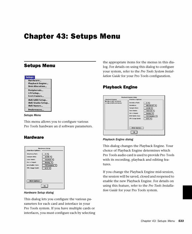
Chapter 43: Setups Menu
Setups Menu
This menu allows you to configure various Pro Tools hardware an d software parameters.
Hardware
This dialog lets you configure the various pa-rameters for each card and interface in your Pro Tools system. If you have multiple cards or interfaces, you must configure each by selecting
Setups Menu
Hardware Setup dialog
the appropriate items for the menus in this dia-log. For details on using this dialog to configure your system, refer to the Pro Tools System Instal-lation Guide for your Pro Tools configuration.
Playback Engine
This dialog changes the Playback Engine. Your choice of Playback Engine determines which Pro Tools audio card is used to provide Pro Tools with its recording, playback and editing fea-tures.
If you change the Playback Engine mid-session, the session will be saved, closed and reopened to enable the new Playback Engine. For details on using this feature, refer to the Pro Tools Installa-tion Guide for your Pro Tools system.
Playback Engine dialog
Chapter 43: Setups Menu 533
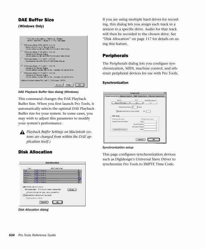
534
DAE Buffer Size(Windows Only)
This command changes the DAE Playback Buffer Size. When you first launch Pro Tools, it automatically selects the optimal DAE Playback Buffer size for your system. In some cases, you may wish to adjust this parameter to modify your system’s performance.
Disk Allocation
DAE Playback Buffer Size dialog (Windows)
Playback Buffer Settings on Macintosh sys-tems are changed from within the DAE ap-plication itself.)
Disk Allocation dialog
Pro Tools Reference Guide
If you are using multiple hard drives for record-ing, this dialog lets you assign each track in a session to a specific drive. Audio for that track will then be recorded to the chosen drive. See “Disk Allocation” on page 117 for details on us-ing this feature.
Peripherals
The Peripherals dialog lets you configure syn-chronization, MIDI, machine control, and eth-ernet peripheral devices for use with Pro Tools.
Synchronization
This page configures synchronization devices such as Digidesign’s Universal Slave Driver to synchronize Pro Tools to SMPTE Time Code.
Synchronization setup
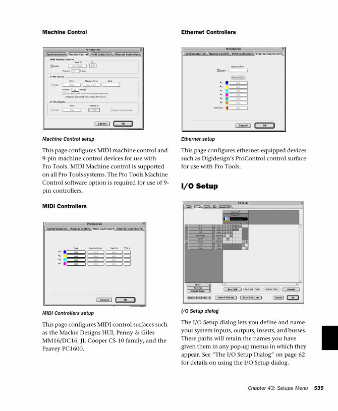
Machine Control
This page configures MIDI machine control and 9-pin machine control devices for use with Pro Tools. MIDI Machine control is supported on all Pro Tools systems. The Pro Tools Machine Control software option is required for use of 9-pin controllers.
MIDI Controllers
This page configures MIDI control surfaces such as the Mackie Designs HUI, Penny & Giles MM16/DC16, JL Cooper CS-10 family, and the Peavey PC1600.
Machine Control setup
MIDI Controllers setup
Ethernet Controllers
This page configures ethernet-equipped devices such as Digidesign’s ProControl control surface for use with Pro Tools.
I/O Setup
The I/O Setup dialog lets you define and name your system inputs, outputs, inserts, and busses. These paths will retain the names you have given them in any pop-up menus in which they appear. See “The I/O Setup Dialog” on page 62 for details on using the I/O Setup dialog.
Ethernet setup
I/O Setup dialog
Chapter 43: Setups Menu 535
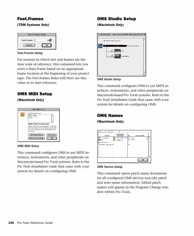
536
Feet.Frames(TDM Systems Only)
For sessions in which feet and frames are the time scale of reference, this command lets you enter a Start Frame based on an appropriate frame location at the beginning of your project tape. The Feet.Frames Ruler will then use this value as its start reference.
OMS MIDI Setup(Macintosh Only)
This command configures OMS to use MIDI in-terfaces, instruments, and other peripherals on Macintosh-based Pro Tools systems. Refer to the Pro Tools Installation Guide that came with your system for details on configuring OMS.
Feet.Frames dialog
OMS MIDI Setup
Pro Tools Reference Guide
OMS Studio Setup(Macintosh Only)
This command configures OMS to use MIDI in-terfaces, instruments, and other peripherals on Macintosh-based Pro Tools systems. Refer to the Pro Tools Installation Guide that came with your system for details on configuring OMS.
OMS Names(Macintosh Only)
This command opens patch name documents for all configured OMS devices and edit patch and note name information. Edited patch names will appear in the Program Change win-dow within Pro Tools.
OMS Studio Setup
OMS Names dialog
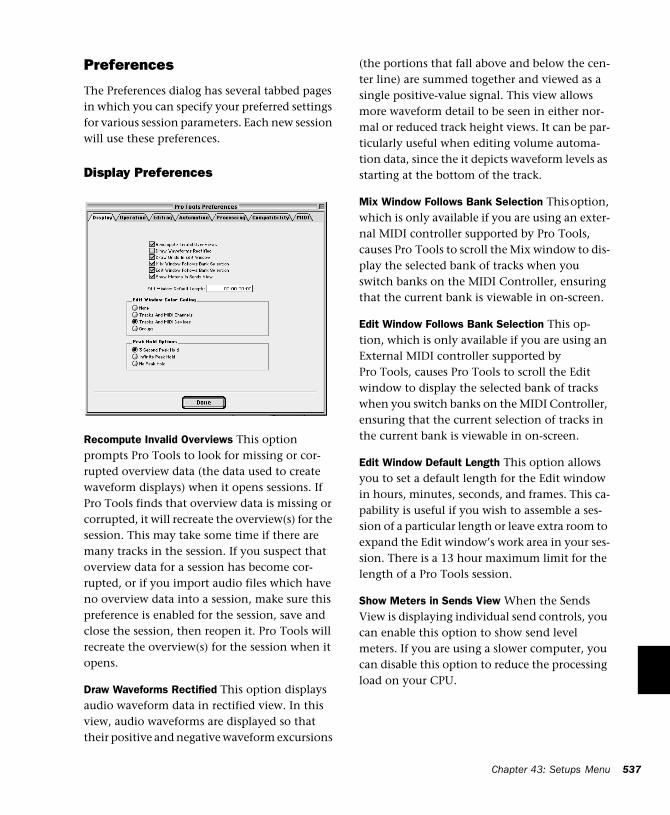
Preferences
The Preferences dialog has several tabbed pages in which you can specify your preferred settings for various session parameters. Each new session will use these preferences.
Display Preferences
Recompute Invalid Overviews This option prompts Pro Tools to look for missing or cor-rupted overview data (the data used to create waveform displays) when it opens sessions. If Pro Tools finds that overview data is missing or corrupted, it will recreate the overview(s) for the session. This may take some time if there are many tracks in the session. If you suspect that overview data for a session has become cor-rupted, or if you import audio files which have no overview data into a session, make sure this preference is enabled for the session, save and close the session, then reopen it. Pro Tools will recreate the overview(s) for the session when it opens.
Draw Waveforms Rectified This option displays audio waveform data in rectified view. In this view, audio waveforms are displayed so that their positive and negative waveform excursions
(the portions that fall above and below the cen-ter line) are summed together and viewed as a single positive-value signal. This view allows more waveform detail to be seen in either nor-mal or reduced track height views. It can be par-ticularly useful when editing volume automa-tion data, since the it depicts waveform levels as starting at the bottom of the track.
Mix Window Follows Bank Selection This option, which is only available if you are using an exter-nal MIDI controller supported by Pro Tools, causes Pro Tools to scroll the Mix window to dis-play the selected bank of tracks when you switch banks on the MIDI Controller, ensuring that the current bank is viewable in on-screen.
Edit Window Follows Bank Selection This op-tion, which is only available if you are using an External MIDI controller supported by Pro Tools, causes Pro Tools to scroll the Edit window to display the selected bank of tracks when you switch banks on the MIDI Controller, ensuring that the current selection of tracks in the current bank is viewable in on-screen.
Edit Window Default Length This option allows you to set a default length for the Edit window in hours, minutes, seconds, and frames. This ca-pability is useful if you wish to assemble a ses-sion of a particular length or leave extra room to expand the Edit window’s work area in your ses-sion. There is a 13 hour maximum limit for the length of a Pro Tools session.
Show Meters in Sends View When the Sends View is displaying individual send controls, you can enable this option to show send level meters. If you are using a slower computer, you can disable this option to reduce the processing load on your CPU.
Chapter 43: Setups Menu 537
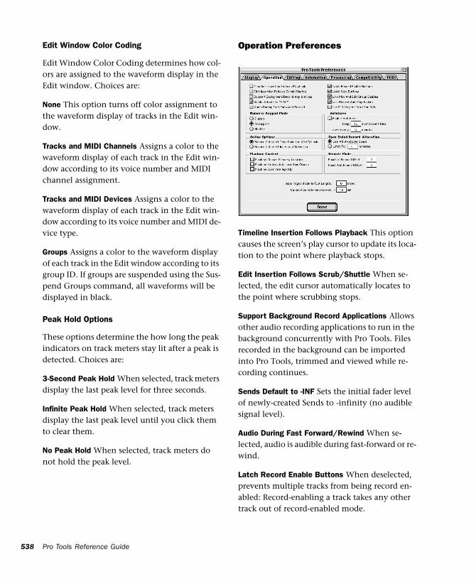
538
Edit Window Color Coding
Edit Window Color Coding determines how col-ors are assigned to the waveform display in the Edit window. Choices are:
None This option turns off color assignment to the waveform display of tracks in the Edit win-dow.
Tracks and MIDI Channels Assigns a color to the waveform display of each track in the Edit win-dow according to its voice number and MIDI channel assignment.
Tracks and MIDI Devices Assigns a color to the waveform display of each track in the Edit win-dow according to its voice number and MIDI de-vice type.
Groups Assigns a color to the waveform display of each track in the Edit window according to its group ID. If groups are suspended using the Sus-pend Groups command, all waveforms will be displayed in black.
Peak Hold Options
These options determine the how long the peak indicators on track meters stay lit after a peak is detected. Choices are:
3-Second Peak Hold When selected, track meters display the last peak level for three seconds.
Infinite Peak Hold When selected, track meters display the last peak level until you click them to clear them.
No Peak Hold When selected, track meters do not hold the peak level.
Pro Tools Reference Guide
Operation Preferences
Timeline Insertion Follows Playback This option causes the screen’s play cursor to update its loca-tion to the point where playback stops.
Edit Insertion Follows Scrub/Shuttle When se-lected, the edit cursor automatically locates to the point where scrubbing stops.
Support Background Record Applications Allows other audio recording applications to run in the background concurrently with Pro Tools. Files recorded in the background can be imported into Pro Tools, trimmed and viewed while re-cording continues.
Sends Default to -INF Sets the initial fader level of newly-created Sends to -infinity (no audible signal level).
Audio During Fast Forward/Rewind When se-lected, audio is audible during fast-forward or re-wind.
Latch Record Enable Buttons When deselected, prevents multiple tracks from being record en-abled: Record-enabling a track takes any other track out of record-enabled mode.
Latch Solo Buttons When deselected, prevents multiple tracks from being soloed. Soloing a track mutes any track that is soloed.
Link Mix and Edit Group Enables When selected, links enabling and disabling of Mix and Edit groups: Enabling Group A in the Edit Window automatically enables Group A in the Mix win-dow.
Use F11 key for Wait for Note When selected, pressing the F11 Function key puts MIDI record-ing in Wait for Note mode.
Numeric Keypad Mode
Numeric Keypad Mode determines how the nu-meric keypad functions. You can always use the numeric keypad to select and enter values in the Event Edit Area, Location Indicators, and Trans-port fields.
Classic Emulates the way Pro Tools worked in versions earlier than 5.0. With the Numeric Key-pad Mode set to Classic, you can play up to two tracks of audio in Shuttle Lock mode. Press Con-trol (Macintosh) or the Start key (Windows), fol-lowed by 0-9 for different play speeds. Press Plus or Minus to reverse direction. Recall Memory Locations by typing the Memory Location num-ber, followed by period.
Transport Allows you to set a number of record and play functions, and also operate the Trans-port from the numeric keypad. With the Nu-meric Keypad Mode set to Transport, you can play up to two tracks of audio in Shuttle Lock mode. Press Control (Macintosh) or the Start key (Windows), followed by 0-9 for different play speeds. Press Plus or Minus to reverse direc-tion. Recall Memory Locations by typing period, the Memory Location number, and period again.
Shuttle Selects a type of shuttling different from that of Shuttle Lock Mode. With the Numeric Keypad Mode set to Shuttle, playback is trig-gered by pressing and holding the keys on the numeric keypad—playback stops once the keys are released. Various playback speeds are avail-able in both forward and reverse. You can also recall Memory Locations by typing period, the Memory Location number, and period again.
Autosave
This preference determines how the Autosave feature functions.
Enable Autosave When selected, Pro Tools auto-matically saves sessions while you work. Use the Keep and Save Every fields to specify the total number of incremental backups that are kept and how often the session is saved.
Online Options
Record Online at Time Code (or ADAT) Lock
When selected, online recording begins as soon as Pro Tools receives and locks to time code or ADAT sync.
Record Online at Insertion/Selection When se-lected, online recording begins at the Edit cursor location. Recording continues until Pro Tools stops receiving time code. If you make a selec-tion, Pro Tools records online for the length of the selection.
Open Ended Record Allocation
This preference determines how much of your available hard drive space is allocated for record-ing. Choices are:
Chapter 43: Setups Menu 539
540
Use All Available Space When selected, the drive’s entire available space is allocated. This can sometimes slow down the recording process for hard drives that use certain file systems, in-cluding HFS+ and NTFS.
Limit To Sets the maximum allowable recording duration. This can help reduce the time it takes to begin recording by allocating only a portion of your hard drive. The number of minutes spec-ified is allocated for each record-enabled track. You may find it necessary to experiment with this number to achieve the desired performance for recording.
Machine Control
These preferences determine how a connected transport responds to Pro Tools. Choices are:
Machine Chases Memory Location When se-lected, navigating to a specific location in a ses-sion with a Memory Location causes a con-nected transport to chase to that location.
Machine Follows Edit Insertion/Scrub When se-lected, navigating to a specific location in a ses-sion by moving the selection point or by scrub-bing a track will cause a connected transport to chase to that location.
Machine Cues Intelligently When selected, if you navigate to a cue point that is more than 10 sec-onds from the current location, Pro Tools will command a connected transport to shuttle to the desired location at full speed to within 10 seconds of the cue point. Cueing will then slow to normal speed until the point is reached. This significantly speeds up tape cueing.
Pro Tools Reference Guide
Remote Mode
Punch In Frame Offset Sets an offset in frames to compensate for punch in timing advances or de-lays.
Punch Out Frame Offset Sets an offset in frames to compensate for punch out timing advances or delays.
Auto Regions Fade In/Out Length Sets a default length for fade ins and fade outs automatically applied to applied to region boundaries. Using automatic fade-ins/fade-outs saves you the trou-ble of editing to zero-crossings or creating nu-merous rendered fades in order to eliminate clicks or pops in playback. Autofades are not written to disk. Value range is from 0 to 10 ms for the Auto Region Fade In/Out Length. A value of zero (the default) means that no auto-fading will occur. The Auto Fade value is saved with the session, and is automatically applied to all free-standing region boundaries until you change it.
Calibration Reference Level Sets a default cali-bration reference level in dB when Pro Tools is in Calibration Mode. See the Pro Tools TDM In-stallation Guide for details on using Calibration Mode.
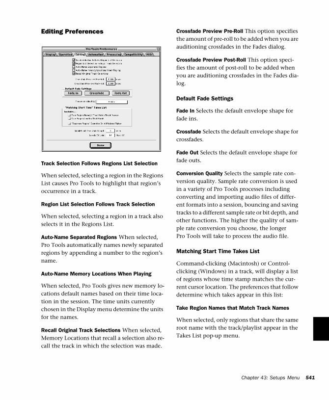
Editing Preferences
Track Selection Follows Regions List Selection
When selected, selecting a region in the Regions List causes Pro Tools to highlight that region’s occurrence in a track.
Region List Selection Follows Track Selection
When selected, selecting a region in a track also selects it in the Regions List.
Auto-Name Separated Regions When selected, Pro Tools automatically names newly separated regions by appending a number to the region’s name.
Auto-Name Memory Locations When Playing
When selected, Pro Tools gives new memory lo-cations default names based on their time loca-tion in the session. The time units currently chosen in the Display menu determine the units for the names.
Recall Original Track Selections When selected, Memory Locations that recall a selection also re-call the track in which the selection was made.
Crossfade Preview Pre-Roll This option specifies the amount of pre-roll to be added when you are auditioning crossfades in the Fades dialog.
Crossfade Preview Post-Roll This option speci-fies the amount of post-roll to be added when you are auditioning crossfades in the Fades dia-log.
Default Fade Settings
Fade In Selects the default envelope shape for fade ins.
Crossfade Selects the default envelope shape for crossfades.
Fade Out Selects the default envelope shape for fade outs.
Conversion Quality Selects the sample rate con-version quality. Sample rate conversion is used in a variety of Pro Tools processes including converting and importing audio files of differ-ent formats into a session, bouncing and saving tracks to a different sample rate or bit depth, and other functions. The higher the quality of sam-ple rate conversion you choose, the longer Pro Tools will take to process the audio file.
Matching Start Time Takes List
Command-clicking (Macintosh) or Control-clicking (Windows) in a track, will display a list of regions whose time stamp matches the cur-rent cursor location. The preferences that follow determine which takes appear in this list:
Take Region Names that Match Track Names
When selected, only regions that share the same root name with the track/playlist appear in the Takes List pop-up menu.
Chapter 43: Setups Menu 541
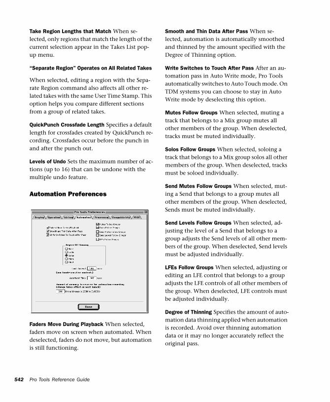
542
Take Region Lengths that Match When se-lected, only regions that match the length of the current selection appear in the Takes List pop-up menu.
“Separate Region” Operates on All Related Takes
When selected, editing a region with the Sepa-rate Region command also affects all other re-lated takes with the same User Time Stamp. This option helps you compare different sections from a group of related takes.
QuickPunch Crossfade Length Specifies a default length for crossfades created by QuickPunch re-cording. Crossfades occur before the punch in and after the punch out.
Levels of Undo Sets the maximum number of ac-tions (up to 16) that can be undone with the multiple undo feature.
Automation Preferences
Faders Move During Playback When selected, faders move on screen when automated. When deselected, faders do not move, but automation is still functioning.
Pro Tools Reference Guide
Smooth and Thin Data After Pass When se-lected, automation is automatically smoothed and thinned by the amount specified with the Degree of Thinning option.
Write Switches to Touch After Pass After an au-tomation pass in Auto Write mode, Pro Tools automatically switches to Auto Touch mode. On TDM systems you can choose to stay in Auto Write mode by deselecting this option.
Mutes Follow Groups When selected, muting a track that belongs to a Mix group mutes all other members of the group. When deselected, tracks must be muted individually.
Solos Follow Groups When selected, soloing a track that belongs to a Mix group solos all other members of the group. When deselected, tracks must be soloed individually.
Send Mutes Follow Groups When selected, mut-ing a Send that belongs to a group mutes all other members of the group. When deselected, Sends must be muted individually.
Send Levels Follow Groups When selected, ad-justing the level of a Send that belongs to a group adjusts the Send levels of all other mem-bers of the group. When deselected, Send levels must be adjusted individually.
LFEs Follow Groups When selected, adjusting or editing an LFE control that belongs to a group adjusts the LFE controls of all other members of the group. When deselected, LFE controls must be adjusted individually.
Degree of Thinning Specifies the amount of auto-mation data thinning applied when automation is recorded. Avoid over thinning automation data or it may no longer accurately reflect the original pass.
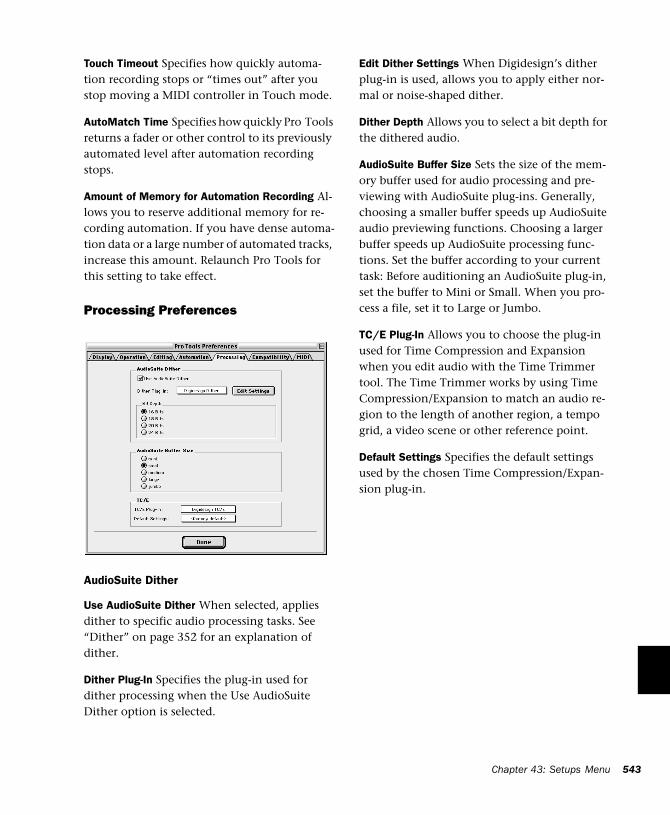
Touch Timeout Specifies how quickly automa-tion recording stops or “times out” after you stop moving a MIDI controller in Touch mode.
AutoMatch Time Specifies how quickly Pro Tools returns a fader or other control to its previously automated level after automation recording stops.
Amount of Memory for Automation Recording Al-lows you to reserve additional memory for re-cording automation. If you have dense automa-tion data or a large number of automated tracks, increase this amount. Relaunch Pro Tools for this setting to take effect.
Processing Preferences
AudioSuite Dither
Use AudioSuite Dither When selected, applies dither to specific audio processing tasks. See “Dither” on page 352 for an explanation of dither.
Dither Plug-In Specifies the plug-in used for dither processing when the Use AudioSuite Dither option is selected.
Edit Dither Settings When Digidesign’s dither plug-in is used, allows you to apply either nor-mal or noise-shaped dither.
Dither Depth Allows you to select a bit depth for the dithered audio.
AudioSuite Buffer Size Sets the size of the mem-ory buffer used for audio processing and pre-viewing with AudioSuite plug-ins. Generally, choosing a smaller buffer speeds up AudioSuite audio previewing functions. Choosing a larger buffer speeds up AudioSuite processing func-tions. Set the buffer according to your current task: Before auditioning an AudioSuite plug-in, set the buffer to Mini or Small. When you pro-cess a file, set it to Large or Jumbo.
TC/E Plug-In Allows you to choose the plug-in used for Time Compression and Expansion when you edit audio with the Time Trimmer tool. The Time Trimmer works by using Time Compression/Expansion to match an audio re-gion to the length of another region, a tempo grid, a video scene or other reference point.
Default Settings Specifies the default settings used by the chosen Time Compression/Expan-sion plug-in.
Chapter 43: Setups Menu 543
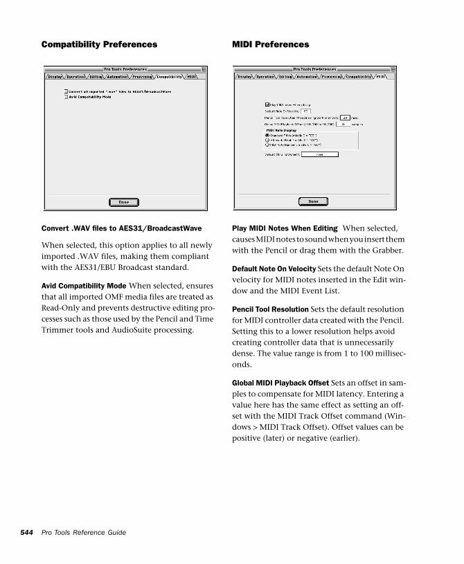
544
Compatibility Preferences
Convert .WAV files to AES31/BroadcastWave
When selected, this option applies to all newly imported .WAV files, making them compliant with the AES31/EBU Broadcast standard.
Avid Compatibility Mode When selected, ensures that all imported OMF media files are treated as Read-Only and prevents destructive editing pro-cesses such as those used by the Pencil and Time Trimmer tools and AudioSuite processing.
Pro Tools Reference Guide
MIDI Preferences
Play MIDI Notes When Editing When selected, causes MIDI notes to sound when you insert them with the Pencil or drag them with the Grabber.
Default Note On Velocity Sets the default Note On velocity for MIDI notes inserted in the Edit win-dow and the MIDI Event List.
Pencil Tool Resolution Sets the default resolution for MIDI controller data created with the Pencil. Setting this to a lower resolution helps avoid creating controller data that is unnecessarily dense. The value range is from 1 to 100 millisec-onds.
Global MIDI Playback Offset Sets an offset in sam-ples to compensate for MIDI latency. Entering a value here has the same effect as setting an off-set with the MIDI Track Offset command (Win-dows > MIDI Track Offset). Offset values can be positive (later) or negative (earlier).
MIDI Note Display Determines how pitches for MIDI notes are displayed in the Edit window and in the MIDI Event List.
Default Thru Instrument Routes MIDI to a De-fault Thru Instrument. This saves you the trou-ble of creating a MIDI track and record enabling it to hear a particular MIDI device and channel. Unlike MIDI tracks, which only listen to the de-vice and channel assigned to its Input Selector, all incoming MIDI data is routed to the Default Thru Instrument. If the Default Thru Instru-ment is assigned to a record-enabled MIDI track, Pro Tools only routes to the record-enabled track.
Chapter 43: Setups Menu 545

546
Pro Tools Reference Guide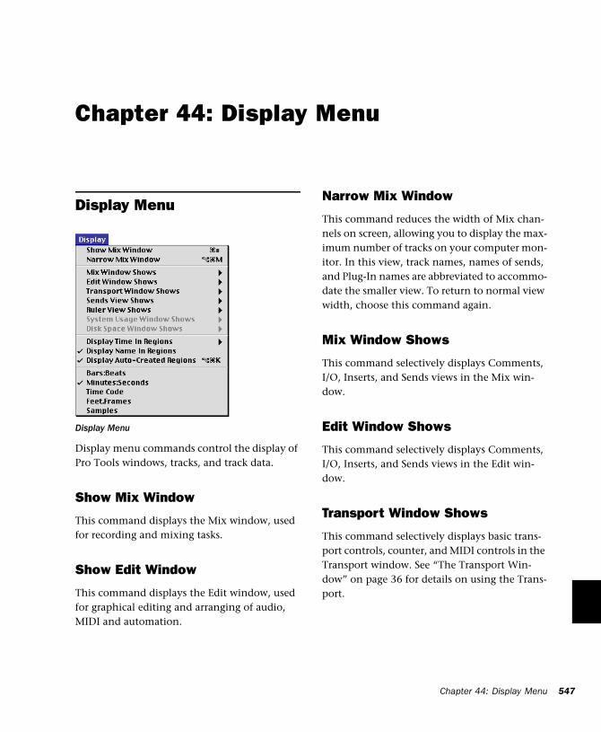
Chapter 44: Display Menu
Display Menu
Display menu commands control the display of Pro Tools windows, tracks, and track data.
Show Mix Window
This command displays the Mix window, used for recording and mixing tasks.
Show Edit Window
This command displays the Edit window, used for graphical editing and arranging of audio, MIDI and automation.
Display Menu
Narrow Mix Window
This command reduces the width of Mix chan-nels on screen, allowing you to display the max-imum number of tracks on your computer mon-itor. In this view, track names, names of sends, and Plug-In names are abbreviated to accommo-date the smaller view. To return to normal view width, choose this command again.
Mix Window Shows
This command selectively displays Comments, I/O, Inserts, and Sends views in the Mix win-dow.
Edit Window Shows
This command selectively displays Comments, I/O, Inserts, and Sends views in the Edit win-dow.
Transport Window Shows
This command selectively displays basic trans-port controls, counter, and MIDI controls in the Transport window. See “The Transport Win-dow” on page 36 for details on using the Trans-port.
Chapter 44: Display Menu 547
548
Sends View Shows
This command displays either send assignments for all sends, or the controls for individual sends.
Ruler View Shows
This command selectively displays various Timebase and Conductor Rulers in the Edit win-dow. In addition to providing a timing reference for track material, Timebase Rulers are used to define Edit selections and Timeline selections. See “Rulers” on page 184 for details on using Rulers.
System Usage Window Shows
This command sets the display format for the System Usage window. The System Usage win-dow shows the usage of DSP and CPU resources during a session. See “About Processing Band-width” on page 376 for details on the System Usage window.
Disk Space Window Shows
This command specifies either a text-based or “gas-gauge” style display format for the Disk Space window. The Disk Space window shows how much recording time is currently available on each hard drive connected to your system.
Pro Tools Reference Guide
Display Time in Regions
This command displays the time stamp of all re-gions in currently placed in tracks. When a re-gion is created, it is time stamped relative to the SMPTE start time specified for the session. This original time stamp is permanently stored with the region and cannot be changed. If a region is ever moved, it can easily be placed at its original position using the Spot dialog.
None Disables time stamp display in regions.
Current Time Displays the time stamp of all re-gions placed in all tracks according to their cur-rent location in the track.
Original Time Stamp Displays the Original Time Stamp of all regions in all tracks.
User Time Stamp Displays the User Time Stamp of all regions in all tracks. When a file is first re-corded, its User Time Stamp is identical to its original time stamp. You can change the User Time Stamp using the Time Stamp Selected command in the Audio Regions List. This allows you to use a custom time stamp for spotting or re-spotting the region to a time location differ-ent from its Original Time Stamp.
Display Name in Regions
This command allows you to hide a region’s name in tracks in the Edit window. This is useful if you are working at a zoom level where region names obscure the view of audio waveforms.
Display Auto-Created Regions
Deselecting this command streamlines the dis-play of region names in the Regions Lists by hid-ing automatically crated regions. These are re-gions that were created as a by-product of cutting, pasting and separating other regions. Since these by-product regions can become nu-merous, hiding them helps you to avoid scroll-ing through unnecessarily long Regions Lists. See “Hiding and Removing Unwanted Regions” on page 257 for details on using this feature.
Bars:Beats
This command displays the Time Scale in Bars & Beats. Use this Time Scale if you are working with musical material that mist align with bars and beats.
Minutes:Seconds
This command displays the time scale in min-utes and seconds.
Time Code(TDM Systems Only)
This command displays the Time Scale in SMPTE frames. The Frame Rate and Session Start time are set from the Session Setup window. Pro Tools supports the following frame rates: 24, 25, 29.97, Non-Drop, 29.97 Drop, 30 Non-Drop, and 30 Drop frames per second.
Feet.Frames(TDM Systems Only)
This command displays the Time Scale in feet and frames for referencing audio-for-film projects. The Feet.Frames time display is based on the 35 millimeter film format.
Samples
This command displays the Time Scale in sam-ples. This format is useful for high-resolution sample editing.
Chapter 44: Display Menu 549

550
Pro Tools Reference Guide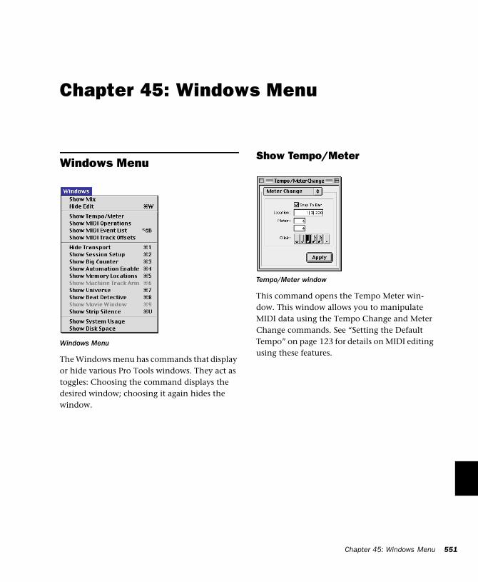
Chapter 45: Windows Menu
Windows Menu
The Windows menu has commands that display or hide various Pro Tools windows. They act as toggles: Choosing the command displays the desired window; choosing it again hides the window.
Windows Menu
Show Tempo/Meter
This command opens the Tempo Meter win-dow. This window allows you to manipulate MIDI data using the Tempo Change and Meter Change commands. See “Setting the Default Tempo” on page 123 for details on MIDI editing using these features.
Tempo/Meter window
Chapter 45: Windows Menu 551
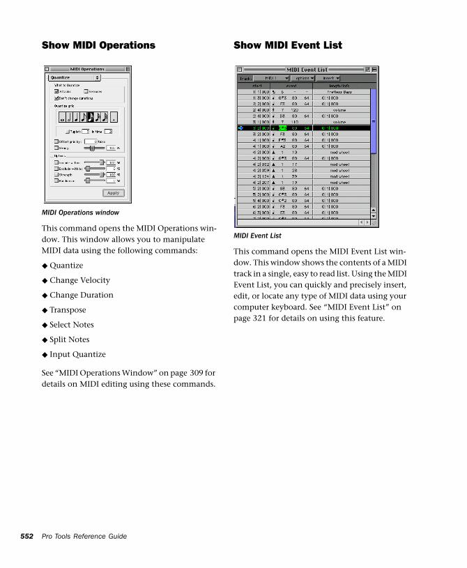
552
Show MIDI Operations
This command opens the MIDI Operations win-dow. This window allows you to manipulate MIDI data using the following commands:
◆ Quantize
◆ Change Velocity
◆ Change Duration
◆ Transpose
◆ Select Notes
◆ Split Notes
◆ Input Quantize
See “MIDI Operations Window” on page 309 for details on MIDI editing using these commands.
MIDI Operations window
Pro Tools Reference Guide
Show MIDI Event List
This command opens the MIDI Event List win-dow. This window shows the contents of a MIDI track in a single, easy to read list. Using the MIDI Event List, you can quickly and precisely insert, edit, or locate any type of MIDI data using your computer keyboard. See “MIDI Event List” on page 321 for details on using this feature.
MIDI Event List
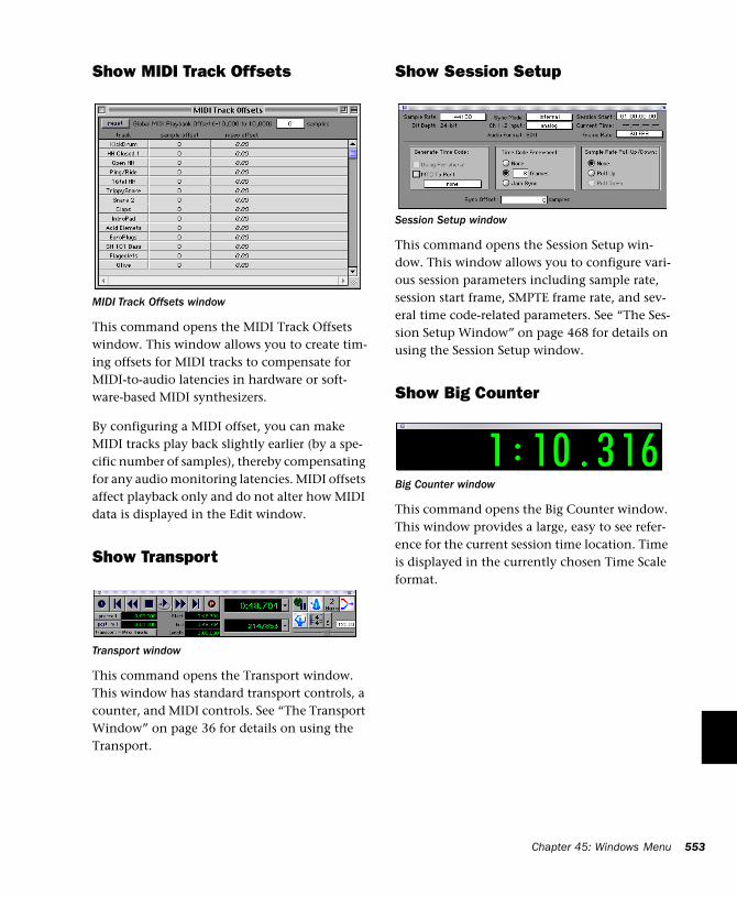
Show MIDI Track Offsets
This command opens the MIDI Track Offsets window. This window allows you to create tim-ing offsets for MIDI tracks to compensate for MIDI-to-audio latencies in hardware or soft-ware-based MIDI synthesizers.
By configuring a MIDI offset, you can make MIDI tracks play back slightly earlier (by a spe-cific number of samples), thereby compensating for any audio monitoring latencies. MIDI offsets affect playback only and do not alter how MIDI data is displayed in the Edit window.
Show Transport
This command opens the Transport window. This window has standard transport controls, a counter, and MIDI controls. See “The Transport Window” on page 36 for details on using the Transport.
MIDI Track Offsets window
Transport window
Show Session Setup
This command opens the Session Setup win-dow. This window allows you to configure vari-ous session parameters including sample rate, session start frame, SMPTE frame rate, and sev-eral time code-related parameters. See “The Ses-sion Setup Window” on page 468 for details on using the Session Setup window.
Show Big Counter
This command opens the Big Counter window. This window provides a large, easy to see refer-ence for the current session time location. Time is displayed in the currently chosen Time Scale format.
Session Setup window
Big Counter window
Chapter 45: Windows Menu 553
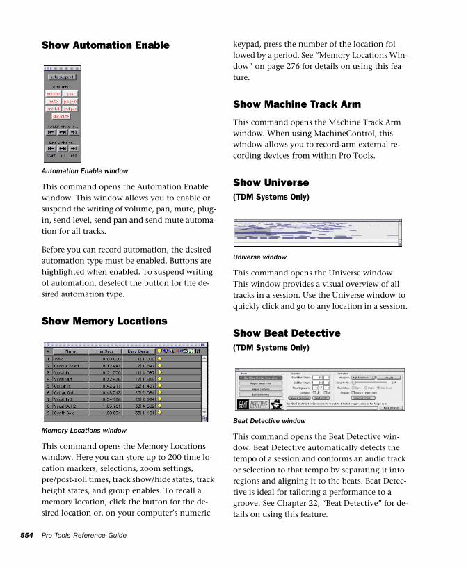
554
Show Automation Enable
This command opens the Automation Enable window. This window allows you to enable or suspend the writing of volume, pan, mute, plug-in, send level, send pan and send mute automa-tion for all tracks.
Before you can record automation, the desired automation type must be enabled. Buttons are highlighted when enabled. To suspend writing of automation, deselect the button for the de-sired automation type.
Show Memory Locations
This command opens the Memory Locations window. Here you can store up to 200 time lo-cation markers, selections, zoom settings, pre/post-roll times, track show/hide states, track height states, and group enables. To recall a memory location, click the button for the de-sired location or, on your computer’s numeric
Automation Enable window
Memory Locations window
Pro Tools Reference Guide
keypad, press the number of the location fol-lowed by a period. See “Memory Locations Win-dow” on page 276 for details on using this fea-ture.
Show Machine Track Arm
This command opens the Machine Track Arm window. When using MachineControl, this window allows you to record-arm external re-cording devices from within Pro Tools.
Show Universe(TDM Systems Only)
This command opens the Universe window. This window provides a visual overview of all tracks in a session. Use the Universe window to quickly click and go to any location in a session.
Show Beat Detective(TDM Systems Only)
This command opens the Beat Detective win-dow. Beat Detective automatically detects the tempo of a session and conforms an audio track or selection to that tempo by separating it into regions and aligning it to the beats. Beat Detec-tive is ideal for tailoring a performance to a groove. See Chapter 22, “Beat Detective” for de-tails on using this feature.
Universe window
Beat Detective window
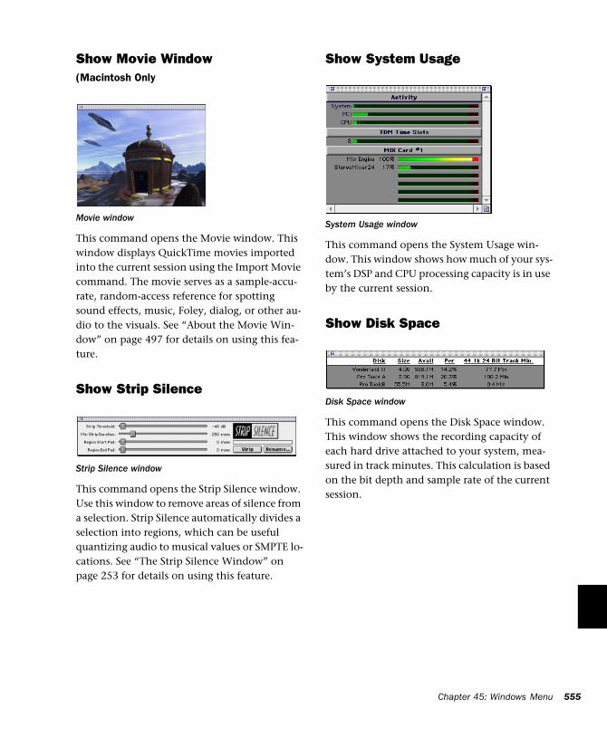
Show Movie Window(Macintosh Only
This command opens the Movie window. This window displays QuickTime movies imported into the current session using the Import Movie command. The movie serves as a sample-accu-rate, random-access reference for spotting sound effects, music, Foley, dialog, or other au-dio to the visuals. See “About the Movie Win-dow” on page 497 for details on using this fea-ture.
Show Strip Silence
This command opens the Strip Silence window. Use this window to remove areas of silence from a selection. Strip Silence automatically divides a selection into regions, which can be useful quantizing audio to musical values or SMPTE lo-cations. See “The Strip Silence Window” on page 253 for details on using this feature.
Movie window
Strip Silence window
Show System Usage
This command opens the System Usage win-dow. This window shows how much of your sys-tem’s DSP and CPU processing capacity is in use by the current session.
Show Disk Space
This command opens the Disk Space window. This window shows the recording capacity of each hard drive attached to your system, mea-sured in track minutes. This calculation is based on the bit depth and sample rate of the current session.
System Usage window
Disk Space window
Chapter 45: Windows Menu 555

556
Pro Tools Reference Guide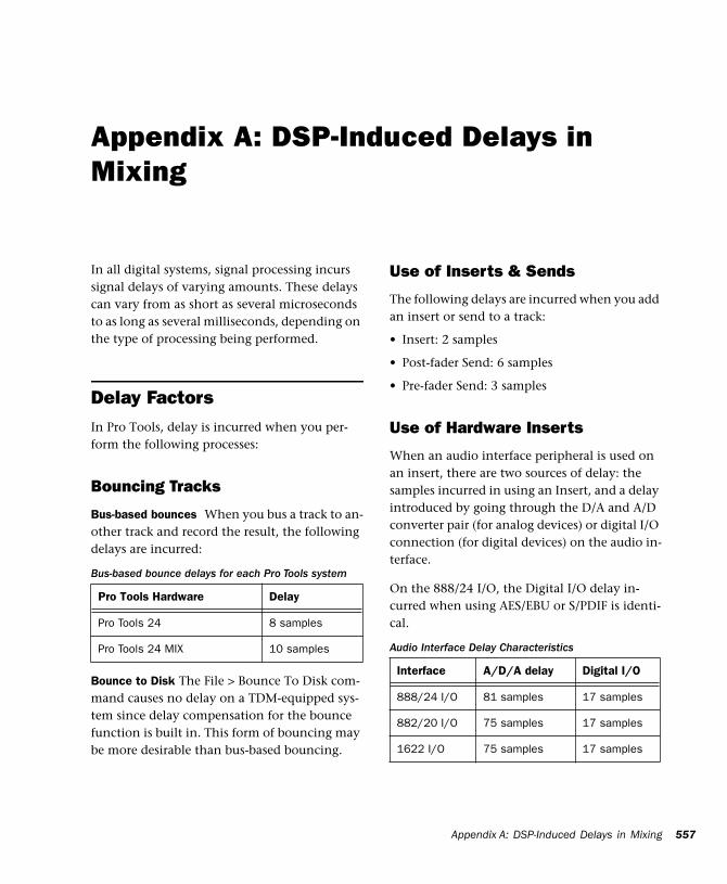
Appendix A: DSP-Induced Delays in Mixing
In all digital systems, signal processing incurs signal delays of varying amounts. These delays can vary from as short as several microseconds to as long as several milliseconds, depending on the type of processing being performed.
Delay FactorsIn Pro Tools, delay is incurred when you per-form the following processes:
Bouncing Tracks
Bus-based bounces When you bus a track to an-other track and record the result, the following delays are incurred:
Bounce to Disk The File > Bounce To Disk com-mand causes no delay on a TDM-equipped sys-tem since delay compensation for the bounce function is built in. This form of bouncing may be more desirable than bus-based bouncing.
Bus-based bounce delays for each Pro Tools system
Pro Tools Hardware Delay
Pro Tools 24 8 samples
Pro Tools 24 MIX 10 samples
Use of Inserts & Sends
The following delays are incurred when you add an insert or send to a track:
• Insert: 2 samples
• Post-fader Send: 6 samples
• Pre-fader Send: 3 samples
Use of Hardware Inserts
When an audio interface peripheral is used on an insert, there are two sources of delay: the samples incurred in using an Insert, and a delay introduced by going through the D/A and A/D converter pair (for analog devices) or digital I/O connection (for digital devices) on the audio in-terface.
On the 888/24 I/O, the Digital I/O delay in-curred when using AES/EBU or S/PDIF is identi-cal.
Audio Interface Delay Characteristics
Interface A/D/A delay Digital I/O
888/24 I/O 81 samples 17 samples
882/20 I/O 75 samples 17 samples
1622 I/O 75 samples 17 samples
Appendix A: DSP-Induced Delays in Mixing 557
558
Compensating for DelaysIf you want to compensate for offsets incurred by these delays, there are two different methods you can use: apply sample-level delay to tracks with the TimeAdjuster plug-in, or physically ad-just tracks in the Edit window by the appropri-ate number of samples.
Using the TimeAdjuster Plug-In
You can use the TimeAdjuster TDM plug-in pro-vided with your Pro Tools system to apply an exact number of samples of delay to the signal path of the tracks you are working with. Up to 2048 samples of delay are available.
Digidesign TDM plug-ins display their delay val-ues in the track delay indicators in the Mix win-dow. TimeAdjuster can be used to match these delay values for tracks that need to remain in phase (such as instruments recorded with multi-ple microphones or stereo pairs).
In the Mix window, Command-click (Macin-tosh) or Control-click (Windows) the Track Level Indicator to toggle between Level (which appears on the display as “vol”), Peak (“pk”) and Channel Delay (“dly”) indications. Delay values are shown in samples.
To use TimeAdjuster to compensate for a time delay:
1 Apply the TimeAdjuster plug-in to the track whose delay you want to increase, and Com-mand-click (Macintosh) or Control-click (Win-dows) its Track Level indicator until the Channel Delay value is displayed for that track.
2 Change the delay time in TimeAdjuster by moving the Delay slider or entering a value in the Delay field, until the track delay value matches that of the first track.
Pro Tools Reference Guide
You can test the delay values by duplicating an audio track and reversing its phase while com-pensating for delay.
If you are using a plug-in whose delay factor are you not familiar with, you can set the delay by ear using one of two methods:
◆ If you are working with phase-coherent track pairs, or tracks that had been multi-miked, you can “null out” the delay. Invert the phase of the target track using the TimeAdjuster Phase Invert button, and adjust the plug-in delay time until the signal disappears. (When they are perfectly synchronized, duplicate signals of opposite po-larity cancel each other out.) When you are fin-ished, disengage the Phase Invert button.
◆ You can also change the delay while listening to the signal in phase, adjusting until any comb-filter effects cancel out.
Nudging Audio Tracks
On audio tracks, you can use the Pro Tools Nudge feature to nudge the affected regions in single-sample (or other) increments, to preserve phase coherency. If it is necessary to nudge a re-gion by a large number of samples, you may want to calculate the equivalent value in milli-seconds and nudge the Region in millisecond increments. If the value doesn’t divide evenly, you can switch the Nudge value back to samples and use these smaller increments for the re-mainder.
The disadvantage of using this method is that it only works with disk tracks (not live inputs), and the timing relationship between tracks is permanently altered, which can affect editing.
Sample Rate and How it Affects Delay
The delay in samples caused by TDM processing is the same regardless of the sample rate because a sample is tied to the rate of the sample clock for the entire system. However, when samples are converted into a time value (milliseconds or microseconds), the sample rate (44.1 versus 48 kHz) must be taken into account.
To convert from samples to milliseconds (and vice-versa) use this formula:
• milliseconds = samples / sample rate (in kHz)
• samples = milliseconds X sample rate (in kHz)
There are 44 samples per millisecond @ 44.1 kHz, and 48 samples/ms. @ 48 kHz.
Here’s an example of how to compensate for a delay:
Imagine that you have used a hardware insert on the 888/24 I/O. According to the guidelines given previously, the total amount of delay in-troduced is:
Insert = 2 samples
888/24 I/O A/D/A = 79 samples
Total = 81 samples
If you are working at 44.1 kHz, set Nudge Value to milliseconds and nudge the region back (ear-lier in time) 2 ms (2 x 44 = 88 samples). Then set Nudge Value to samples, and nudge it forward (later in time) 7 samples for a total of 81 sam-ples.
There are actually 44.1 samples/ms at 44.1 kHz, so Pro Tools rounds down to 44 samples/ms. One time in ten, Pro Tools rounds off to 45 samples/ms. At 48 kHz, no rounding occurs.
Typical Delay Scenarios Below are some typical delay scenarios that you may encounter in a Pro Tools session. The more complex a session becomes, the greater the TDM delay factors may become.
Once you know the delay for your session, set the Nudge Value to that amount (in samples) and nudge the affected regions to compensate for the delay.
Example 3, Pro Tools 24 MIX System
A bus-based TDM bounce with no plug-ins adds 10 samples of delay:
◆ Track 1 routed to Bus 1-2, with pan set <100 = 2 samples
◆ Through Bus 1-2 Mixer and back out to TDM = 5 samples
◆ Record to Track 2 with input set to Bus 1 = 3 samples
Total: 10 samples
Example 2, Pro Tools 24 MIX System
A slightly different bounce adds 14 samples of delay because it involves use of a Send:
◆ Track 1/Send 1 (post-fader) routed to Bus 1 = 6 samples
◆ Through Bus 1-2 Mixer and back out to TDM = 5 samples
◆ Record to Track 2 with input set to Bus 1 = 3 samples
Total: 14 samples
Appendix A: DSP-Induced Delays in Mixing 559
560
Example 1, Pro Tools 24 System
A bus-based TDM bounce with no plug-ins adds 8 samples of delay:
◆ Track 1 routed to Bus 1-2, with pan set <100 = 2 samples
◆ Through Bus 1-2 Mixer and back out to TDM = 3 samples
◆ Record to Track 2 with input set to Bus 1 = 3 samples
Total: 8 samples
Example 2, Pro Tools 24 System
A slightly different bounce adds 11 samples of delay because it involves use of a Send:
• Track 1/Send 1 (post-fader) routed to Bus 1 = 5 samples
• Through Bus 1-2 Mixer and back out to TDM = 3 samples
• Record to Track 2 with input set to Bus 1 = 3 samples
Total: 11 samples
Pro Tools Reference Guide
Appendix B: TDM Mixing and DSP Usage
Pro Tools TDM Technology(TDM Systems Only)
Digidesign’s TDM (or time division multiplexing) technology is based on the concept of a single, high-speed data highway, or bus. In Pro Tools 24 MIX and Pro Tools 24 systems, in-dividual channels from sources such as disk tracks, sends, or busses are sent out from Digide-sign audio cards, and combined together or mul-tiplexed onto the TDM bus. At the receiving end, the audio cards can listen to any connection on the bus, and take whatever data they need.
With Pro Tools 24 MIX and Pro Tools 24 sys-tems, you can choose how to allocate the pro-cessing power of your system. In most cases, you’ll start the allocation process by configuring your mixer, then assigning plug-in effects ac-cording to how much remaining processing power you have.
DSP Allocation(TDM Systems Only)
Digital Signal Processing (or DSP) capability is one of the most powerful elements of your sys-tem. The DSP chips in your system provide the real-time processing power for your TDM Mixer and plug-ins. There is a limit, depending on your system, to how many functions a single DSP chip can power at once. This section con-tains some guidelines for getting the most from your available DSP capacity.
DSP Allocation Basics
As in the analog world, every send bus or output mix that you use demands that a summing mixer exist for that group. On an analog con-sole, the number of these summing mixers is fixed by the physical layout of the console. In the Pro Tools mix environment, this number is variable, and depends on the number of output mixes or sends that you choose to create. Pro Tools allocates DSP power as it is needed to build the mixers for each session.
Appendix B: TDM Mixing and DSP Usage 561
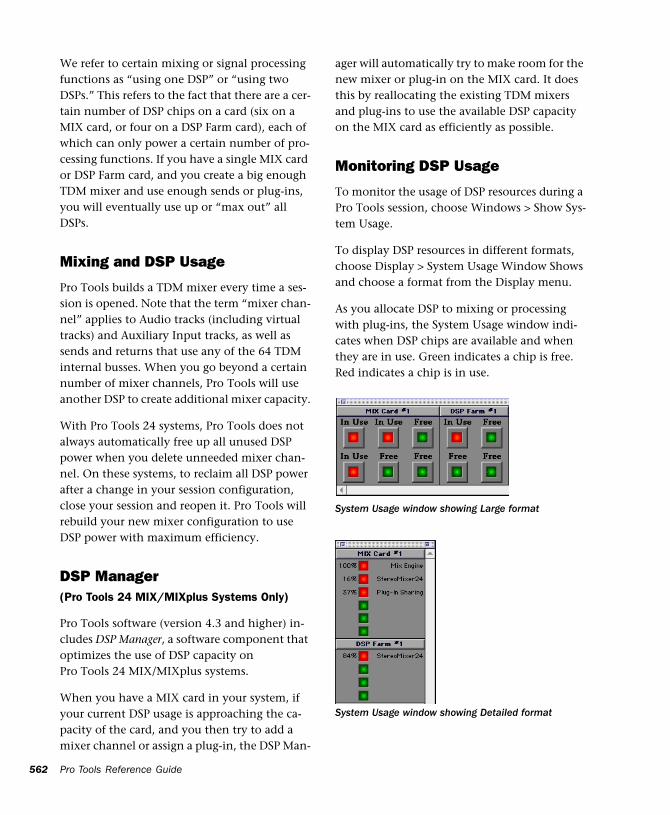
562
We refer to certain mixing or signal processing functions as “using one DSP” or “using two DSPs.” This refers to the fact that there are a cer-tain number of DSP chips on a card (six on a MIX card, or four on a DSP Farm card), each of which can only power a certain number of pro-cessing functions. If you have a single MIX card or DSP Farm card, and you create a big enough TDM mixer and use enough sends or plug-ins, you will eventually use up or “max out” all DSPs.
Mixing and DSP Usage
Pro Tools builds a TDM mixer every time a ses-sion is opened. Note that the term “mixer chan-nel” applies to Audio tracks (including virtual tracks) and Auxiliary Input tracks, as well as sends and returns that use any of the 64 TDM internal busses. When you go beyond a certain number of mixer channels, Pro Tools will use another DSP to create additional mixer capacity.
With Pro Tools 24 systems, Pro Tools does not always automatically free up all unused DSP power when you delete unneeded mixer chan-nel. On these systems, to reclaim all DSP power after a change in your session configuration, close your session and reopen it. Pro Tools will rebuild your new mixer configuration to use DSP power with maximum efficiency.
DSP Manager (Pro Tools 24 MIX/MIXplus Systems Only)
Pro Tools software (version 4.3 and higher) in-cludes DSP Manager, a software component that optimizes the use of DSP capacity on Pro Tools 24 MIX/MIXplus systems.
When you have a MIX card in your system, if your current DSP usage is approaching the ca-pacity of the card, and you then try to add a mixer channel or assign a plug-in, the DSP Man-
Pro Tools Reference Guide
ager will automatically try to make room for the new mixer or plug-in on the MIX card. It does this by reallocating the existing TDM mixers and plug-ins to use the available DSP capacity on the MIX card as efficiently as possible.
Monitoring DSP Usage
To monitor the usage of DSP resources during a Pro Tools session, choose Windows > Show Sys-tem Usage.
To display DSP resources in different formats, choose Display > System Usage Window Shows and choose a format from the Display menu.
As you allocate DSP to mixing or processing with plug-ins, the System Usage window indi-cates when DSP chips are available and when they are in use. Green indicates a chip is free. Red indicates a chip is in use.
System Usage window showing Large format
System Usage window showing Detailed format
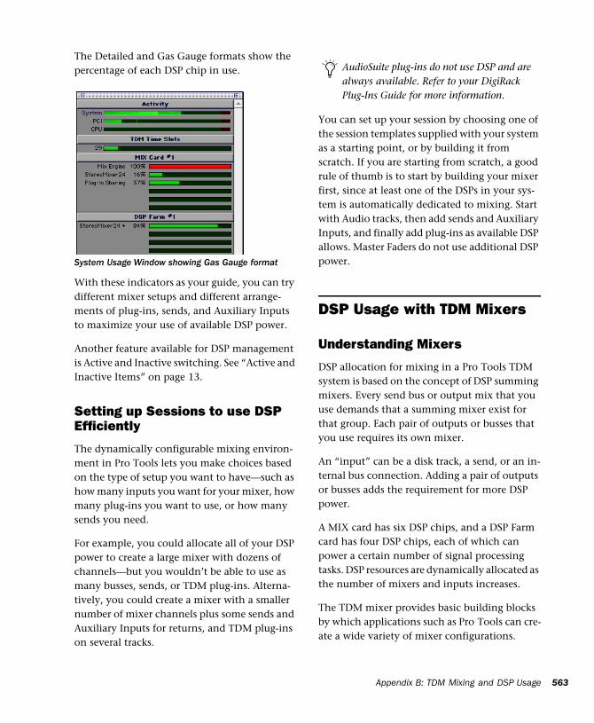
The Detailed and Gas Gauge formats show the percentage of each DSP chip in use.
With these indicators as your guide, you can try different mixer setups and different arrange-ments of plug-ins, sends, and Auxiliary Inputs to maximize your use of available DSP power.
Another feature available for DSP management is Active and Inactive switching. See “Active and Inactive Items” on page 13.
Setting up Sessions to use DSP Efficiently
The dynamically configurable mixing environ-ment in Pro Tools lets you make choices based on the type of setup you want to have—such as how many inputs you want for your mixer, how many plug-ins you want to use, or how many sends you need.
For example, you could allocate all of your DSP power to create a large mixer with dozens of channels—but you wouldn’t be able to use as many busses, sends, or TDM plug-ins. Alterna-tively, you could create a mixer with a smaller number of mixer channels plus some sends and Auxiliary Inputs for returns, and TDM plug-ins on several tracks.
System Usage Window showing Gas Gauge format
You can set up your session by choosing one of the session templates supplied with your system as a starting point, or by building it from scratch. If you are starting from scratch, a good rule of thumb is to start by building your mixer first, since at least one of the DSPs in your sys-tem is automatically dedicated to mixing. Start with Audio tracks, then add sends and Auxiliary Inputs, and finally add plug-ins as available DSP allows. Master Faders do not use additional DSP power.
DSP Usage with TDM Mixers
Understanding Mixers
DSP allocation for mixing in a Pro Tools TDM system is based on the concept of DSP summing mixers. Every send bus or output mix that you use demands that a summing mixer exist for that group. Each pair of outputs or busses that you use requires its own mixer.
An “input” can be a disk track, a send, or an in-ternal bus connection. Adding a pair of outputs or busses adds the requirement for more DSP power.
A MIX card has six DSP chips, and a DSP Farm card has four DSP chips, each of which can power a certain number of signal processing tasks. DSP resources are dynamically allocated as the number of mixers and inputs increases.
The TDM mixer provides basic building blocks by which applications such as Pro Tools can cre-ate a wide variety of mixer configurations.
AudioSuite plug-ins do not use DSP and are always available. Refer to your DigiRack Plug-Ins Guide for more information.
Appendix B: TDM Mixing and DSP Usage 563
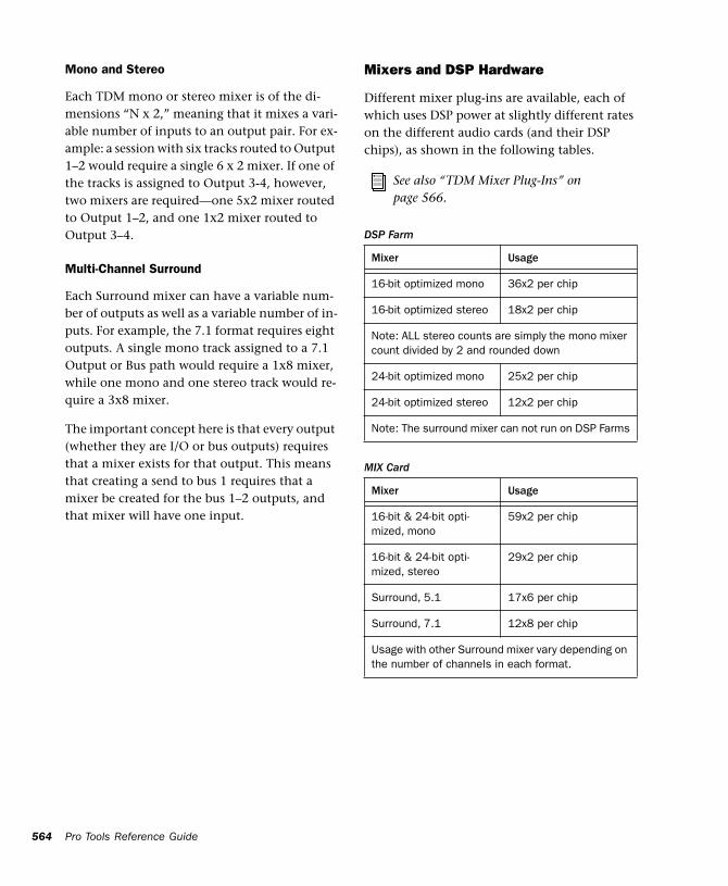
564
Mono and Stereo
Each TDM mono or stereo mixer is of the di-mensions “N x 2,” meaning that it mixes a vari-able number of inputs to an output pair. For ex-ample: a session with six tracks routed to Output 1–2 would require a single 6 x 2 mixer. If one of the tracks is assigned to Output 3-4, however, two mixers are required—one 5x2 mixer routed to Output 1–2, and one 1x2 mixer routed to Output 3–4.
Multi-Channel Surround
Each Surround mixer can have a variable num-ber of outputs as well as a variable number of in-puts. For example, the 7.1 format requires eight outputs. A single mono track assigned to a 7.1 Output or Bus path would require a 1x8 mixer, while one mono and one stereo track would re-quire a 3x8 mixer.
The important concept here is that every output (whether they are I/O or bus outputs) requires that a mixer exists for that output. This means that creating a send to bus 1 requires that a mixer be created for the bus 1–2 outputs, and that mixer will have one input.
Pro Tools Reference Guide
Mixers and DSP Hardware
Different mixer plug-ins are available, each of which uses DSP power at slightly different rates on the different audio cards (and their DSP chips), as shown in the following tables.
See also “TDM Mixer Plug-Ins” on page 566.
DSP Farm
Mixer Usage
16-bit optimized mono 36x2 per chip
16-bit optimized stereo 18x2 per chip
Note: ALL stereo counts are simply the mono mixer count divided by 2 and rounded down
24-bit optimized mono 25x2 per chip
24-bit optimized stereo 12x2 per chip
Note: The surround mixer can not run on DSP Farms
MIX Card
Mixer Usage
16-bit & 24-bit opti-mized, mono
59x2 per chip
16-bit & 24-bit opti-mized, stereo
29x2 per chip
Surround, 5.1 17x6 per chip
Surround, 7.1 12x8 per chip
Usage with other Surround mixer vary depending on the number of channels in each format.
I/O
If the DSP is also being used for I/O processing, then some of the chip’s capacity will be devoted to I/O, yielding slightly lower mixer count (these figures represent maximum numbers when I/O is declared in the Hardware Setup dia-log):
DSP Farm with one I/O Declared
Mixer Usage
16-bit optimized mono 30x2 per chip
16-bit optimized stereo 15x2 per chip
24-bit optimized mono 20x2 per chip
24-bit optimized stereo 10x2 per chip
Note: The surround mixer cannot run on DSP Farms, or any DSP that has I/O declared
MIX Card with one I/O declared
Mixer Usage
16-bit & 24-bit opti-mized, mono
51x2 per chip
16-bit & 24-bit opti-mized, stereo
25x2 per chip
Note: The Surround mixer cannot run on a MIX card with I/O declared
MIX Card with two I/Os declared
Mixer Usage
16-bit & 24-bit opti-mized, mono
43x2 per chip
16-bit & 24-bit opti-mized, stereo
21x2 per chip
Note: The Surround mixer cannot run on a MIX card with I/O declared
Submixing
When there is no space remaining on any DSP for a single mixer to increase the number of in-puts, summing mixers must be created. For ex-ample, on a Pro Tools 24 system, when a 24-bit Optimized mixer needs to grow to more than 26 inputs, a summing mixer is created along with another 1 x 2 mixer to handle the 27th input. Both the original 26 x 2 mixer and the new 1 x 2 mixer are routed to the new summing mixer, whose outputs go to the desired destination (such as output 1-2).
Keep in mind that any delays inherent in creat-ing the summing mixer are equal. Since input signals are delayed equally, phase coherency is preserved.
The number of virtual tracks supported by your particular Pro Tools configuration will ulti-mately determine the maximum number of channels for your TDM mixer.
Sends, Busses, and Master Faders
Each send will add an input to the destination output pair. For example, a send to output 1 will add another input to the output 1–2 mixer. If the send destination doesn’t already have a mixer for its output pair, then a new mixer will be created. A send to bus 3 will make a 1x2 mixer for bus 3–4 if no other bus 3–4 sources have been created yet.
In addition, adding a new track and assigning its input to a bus source will create a mixer for that bus pair if there isn’t one already. For example, creating a new Auxiliary Input track and setting its input to bus 5 will create a 1x2 mixer for bus 5–6, even if no sources have been created yet.
Appendix B: TDM Mixing and DSP Usage 565
566
TDM Mixer Plug-Ins(TDM Systems Only)
Pro Tools TDM systems come with three differ-ent Mixer plug-ins: Surround, 24-bit Optimized, and 16-bit Optimized. In most cases, the Mixer plug-in that was automatically installed with your system is the best one for all around use. The Mixer plug-in that is installed depends on which Pro Tools system you have:
Pro Tools 24 MIX Systems Only The Surround Mixer plug-in is installed by default. When you run your Pro Tools Installer, a copy of the 24-bit Optimized and 16-bit Optimized Mixers are placed in the folder “Plug-Ins (Unused)”.
Pro Tools 24 Systems Only The 24-bit Optimized Mixer is installed by default. When you run the Pro Tools Installer, a copy of the 16-bit Opti-mized Mixer is placed in the folder “Plug-Ins (Unused)”.
Switching TDM Mixer Plug-Ins
To Switch TDM mixer plug-ins:
1 Quit Pro Tools.
2 Open the DAE Folder. The DAE folder is in-stalled at the root level of the System Folder.
3 Open the “Plug-Ins (Unused)” folder, locate the Mixer plug-in that you want to use, and drag it to the Plug-Ins folder.
4 Open the Plug-Ins folder, locate the other Mixer plug-in, and drag it to the “Plug-Ins (Un-used)” folder.
5 Launch Pro Tools.
Pro Tools Reference Guide
Mixer Usage Guidelines
The following conditions apply to mixing with Pro Tools 24 MIX and Pro Tools 24 systems.
◆ One DSP chip is automatically dedicated to mixing in the TDM environment.
◆ As you reach the basic mixer limits for a single DSP chip, the system will automatically begin allocating DSP resources from another chip (if available), making it unavailable for plug-ins.
◆ Each bus or send connection requires DSP to mix signals. This means that each send or Aux-iliary Input that you create will use available DSP.
◆ On Pro Tools 24 systems, the 16-bit Opti-mized Mixer can power more channels per DSP chip than the 24-bit Optimized Mixer plug-in. There may be cases where using the 16-bit Opti-mized mixer will help conserve enough DSP power to allow for additional plug-ins.
On Pro Tools 24 MIX systems, there is no ad-vantage to using the 16-bit Optimized mixer, so you should always use either the Surround mixer, or the 24-bit Optimized mixer.
Plug-In Features
Surround and 24-Bit Optimized
Both the 24-bit Optimized Mixer and the Sur-round Mixer plug-ins provide the following:
◆ Optimized performance for recording and mixing 24-bit audio.
◆ 24-bit digital output, from an audio interface output or Bounce to Disk. Mixing level scaling stores 48-bit results, using a 56-bit accumulator for maximum precision.
◆ 30 dB of mix headroom
◆ Input and Output clip indication: Master Fader meters simultaneously indicate clipping at both the input summing stage and the output level stage.
◆ Multi-channel mixing formats for surround (available with the Surround Mixer on Pro Tools MIX systems only).
16-bit Optimized Mixer
The 16-bit Optimized Mixer provides:
◆ Optimized performance for recording and mixing 16-bit audio
◆ 24-bit digital output mix result from an audio interface output, or when bouncing to disk
◆ More mixing channels (On TDM systems, 36 x 2 mixing channels can be created per DSP)
◆ 18 dB of mix headroom
◆ Output clip indication: Master Fader meters indicate clipping at the input summing stage only.
Preventing Clipping
The 24-bit Optimized and the 16-bit Optimized Mixer plug-ins indicate clipping differently.
24-bit Optimized Mixer With the 24-bit Opti-mized mixer, the Master Fader meters indicate clipping at both the input summing stage and the output level stage at all times. With this mixer, you could lower the Master Fader to re-duce your output level, but the Master Fader meters could still indicate clipping at the input stage.
16-bit Optimized Mixer With the 16-bit Opti-mized Mixer, the Master Fader meters indicate clipping only for the output level stage of the mixer. With this mixer, you could lower the Master Fader to reduce your output level, but any clipping at the input stage would not be in-dicated.
If reducing the output level has no effect on clipping, it could be occurring in one of the fol-lowing places:
◆ At the input summing stage. To prevent clip-ping at the input stage, trim the input summing levels.
◆ At an insert on the Master Fader. If you are us-ing a plug-in on the Master Fader, its meters show the levels on the insert. To prevent clip-ping at the insert, trim levels on any plug-ins or Hardware inserts on the Master Fader.
Trimming Input Summing Levels
With many inputs that contain hi-level signals, it is possible to clip the input summing stage of the 16-bit Optimized Mixer. (This is less likely to happen on the 24-bit Optimized Mixer because of its much greater available headroom.)
To reduce the levels going into the input sum-ming stage of the Mixer plug-in, lower the fader levels of all track faders using the All Mix/Edit group. If you are using mix automation, you will need to use Automation Trim mode or the Trim tool to lower the overall volume of all tracks un-til the levels are low enough to not overload the Master Faders.
Appendix B: TDM Mixing and DSP Usage 567
568
DSP Usage with TDM Plug-InsSome basic guidelines for DSP usage on Pro Tools systems follow:
◆ TDM-equipped systems running Pro Tools 4.3 or higher software use Digidesign’s MultiShell technology, that lets any MultiShell compatible plug-in to share DSP chips on both MIX cards and DSP Farm cards. Up to five types of Multi-Shell compatible plug-ins can share a single DSP chip.
◆ Stereo DSP plug-ins generally use up twice as much DSP as mono plug-ins.
◆ Master Faders don’t require additional DSP. Use them freely to control submix levels, send/bus output levels, and the master output level of your session.
The session templates provided with your sys-tem include several useful preconfigured session setups that make efficient use of DSP resources.
If your computer has unused slots, you can al-ways increase your available DSP resources by adding additional MIX Farm or DSP Farm cards to your system.
Refer to the DigiRack Plug-Ins Guide for de-tails on MultiShell plug-ins.
Pro Tools Reference Guide
DSP Usage and I/O AllocationOn TDM-equipped Pro Tools systems with a sin-gle audio interface, at least one DSP chip on your MIX card (Pro Tools 24 MIX systems) or DSP Farm (Pro Tools 24) is automatically allo-cated to mixing and input and output tasks. See “Mixers and DSP Hardware” on page 564 for specifics.
Even though this is only a small portion of the DSP power available on the chip, it effectively dedicates the entire chip to mixing tasks, mak-ing it unavailable for plug-ins.
If you have an additional audio interface as-signed to a DSP Farm or MIX Farm card, Pro Tools will use a DSP chip on that card for mixing and I/O tasks as well.
If you are not currently using your additional in-terface, you can free up DSP and use it for addi-tional plug-ins.
To reallocate I/O capacity on a DSP Farm or MIX Farm card:
1 Choose Setups > Playback Engine.
2 From the Card pop-up menu, select the MIX Farm or DSP Farm whose DSP you want to real-locate.
3 From the Interface pop-up, select No Inter-face.
4 Click OK to close this dialog.
When the session reopens, the DSP that was al-located to I/O is available for mixing or plug-ins.
Appendix C: Troubleshooting
Backing Up Your workIt is highly recommended that you back up your work on a regular basis, and especially before making changes to your system configuration.
Back Up Your Session Data
Back up your session and audio data frequently. There are a variety of media that are suited to back up projects of various sizes, from auto-mated tape backup systems to high-capacity op-tical drives, to desktop CD-R burners.
The best way to back up a session is to use the Save Session Copy In command to save the ses-sion file and all of its associated files to a new lo-cation.
Back Up Your System Setup
Macintosh Back up your System Folder before upgrading your OS.
Windows Create a system recovery disk after you have finished configuring your system and in-stalling software. This is more useful than a re-covery disk for an unconfigured system.
Common Issues
Pro Tools Won’t Launch
Problem:
When you double-click the Pro Tools applica-tion or a Pro Tools session file, Pro Tools doesn’t launch.
Possible Solutions:
◆ (TDM systems only) Turn off your computer and check to be sure your cables are properly and securely connected to the correct Pro Tools cards and to your audio interfaces.
◆ (Digi 001 systems only) Turn off your com-puter and check to be sure your cable is properly and securely connected to the Digi 001 PCI card and to the Digi 001 I/O Box.
◆ Turn off your computer and check all Pro Tools cards installed in your computer to be sure they are properly seated in their PCI slots, and that any TDM ribbon cables are connected properly.
◆ Verify that Pro Tools cards are installed in the correct slot order in your computer or Expan-sion Chassis.
◆ Check to be sure your computer has the re-quired amount of RAM to launch Pro Tools.
Appendix C: Troubleshooting 569
570
◆ (Macintosh Only) Verify that the DAE appli-cation is installed in the proper location. It should be in the DAE Folder inside your System Folder. If DAE is not installed in the proper loca-tion, use your Pro Tools Installer disc to install it.
◆ (Macintosh Only) Verify that the DigiSystem INIT is installed in the Extensions folder, inside the System Folder. If it is not, use your Pro Tools Installer disc to install it.
◆ (Macintosh Only) Verify that Virtual Memory is turned off. On the Macintosh, open the Mem-ory Control Panel. If Virtual Memory is turned on, turn it off and restart your computer.
Problem:
You get an error message when you try to start the Pro Tools application.
Possible Solutions:
◆ (Macintosh) Make sure the default set of Mac OS System Extensions is enabled, along with the OMS, DigiSystem Init, Direct I/O, and DSP Man-ager Extensions.
◆ Try a complete restart. (Turn off your audio in-terfaces, computer peripherals and your com-puter, and then turn them on again in the proper sequence.)
◆ Use the DigiTest application (installed in the Pro Tools Utilities folder) as a diagnostic tool to verify that your Digidesign cards are opera-tional. You need to restart your computer before and after using the DigiTest utility.
Pro Tools Reference Guide
Audio Interface Isn’t Recognized(TDM Systems Only)
Problem:
When you launch Pro Tools it does not recog-nize an audio interface, or a connected audio in-terface is not available.
Possible Solutions:
◆ Turn off your computer and check to be sure your cables are properly and securely connected to the correct Pro Tools cards and to your audio interfaces.
◆ Verify that your Hardware Setup is correct; check to see that you have selected the correct Interfaces for each I/O card.
◆ If you only have one interface, make sure it is connected to the d24 card (Pro Tools 24), or MIX Core card (Pro Tools 24 MIX).
◆ Make sure SuperClock connections to your audio interface are correct. Disconnect the SuperClock source from the interface and see if the problem persists.
Using DigiTest As a Diagnostic ToolThe DigiTest utility performs diagnostic tests on the Pro Tools cards in your system. If DigiTest reports that any of your cards have failed, click the Info button next to that card. Write down the information that appears and report it to your local Digidesign dealer or a Digidesign Technical Support Representative.
Refer to your TDM System Installation Guide for the specific DigiTest instructions.
Performance FactorsThere are several conditions that may adversely affect the performance of Pro Tools. These in-clude:
Network Connections Close any network con-nections unless you are using them for network interchange of audio data.
Background Applications Any software utilities that run in the background or generate disk ac-tivity, such as virus protection software, disk op-timizing, or file savers, should be turned off or removed.
Screen Savers Screen saver software should be completely removed from your computer before running Pro Tools.
Power Saver Features Some automatic power saver features, such as those that spin down the system hard drive, can affect Pro Tools perfor-mance. These features should be turned off.
Virtual Memory (Macintosh Only) Pro Tools will not launch if Virtual Memory is active. De-activate Virtual Memory and restart your Macin-tosh.
CD-ROM Extensions/Control Panels Some CD-ROM and removable media Extensions and Control Panels have been linked to audio qual-ity problems. Deactivate any performance-en-hancing Extension or Control Panels for such media, and restart your computer.
Before You Call Digidesign Technical Support
Register Your System
As a registered owner of a new Digidesign prod-uct under warranty, you are eligible to receive Digidesign Technical Support. Fill out and sign your Registration Form and mail or fax it to the address supplied with the registration materials.
Refer to the registration materials that came with your system for details on warranty cover-age and the range of services available.
Use Digidesign Resources
In addition to the Pro Tools Guides, your system includes following sources of information:
ReadMe files These contain late-breaking infor-mation and known issues pertaining to Pro Tools software and hardware configura-tions. ReadMe files are installed in the Release Notes and Documentation folder when you install Pro Tools.
Answerbase This is a database of common prob-lems and DAE errors, and their solutions based on the latest information from Digidesign Tech-nical Support. This database is installed in the Digidesign folder when you install Pro Tools.
Web site The Digidesign website includes an area for Technical Support, as well as a User Conference that includes technical discussions. Visit www.digidesign.com and go to the Support area or the User Conference area.
Appendix C: Troubleshooting 571
572
Gather Important Information
Digidesign wants to help you resolve problems as quickly and efficiently as possible. If you have the following information handy when you contact Technical Support, it will make the diag-nosis of your problem easier. Take a few minutes to collect this basic information in one place.
System Information
Computer
◆ Make, Model, processor speed
◆ Amount of system RAM
◆ Operating system (version of Mac OS or Win-dows)
◆ Any Drivers, Extensions, Control Panels, Disk Utilities, or other system-related applications you may have installed.
Digidesign Hardware
◆ Type of cards, interfaces, or peripherals
◆ Where the cards are installed
◆ PCI card order in computer or chassis
◆ Interfaces connected to each card
Hard Drives
◆ Make, Model
◆ Speed (RPM)
◆ Type of SCSI Connection (narrow, wide)
Digidesign Software
◆ Pro Tools software version
◆ (Macintosh) DAE and DSI versions
◆ Plug-in versions
◆ Other Digidesign software
◆ Additional plug-ins from Digidesign Develop-ment Partners
Pro Tools Reference Guide
Other Hardware
If you are using additional hardware, refer to the manufacturer’s documentation for operational details.
The most common hardware additions include the following:
◆ SCSI Accelerators (manufacturer, model, set-tings)
◆ Expansion Chassis (manufacturer, model, bridge chip type)
◆ Video Capture cards (manufacturer, model)
Refer to Digidesign’s compatibility documents or contact your Digidesign dealer to verify that the hardware has been qualified for use with your Pro Tools system.
Other Software
If you are using other audio or video applica-tions, refer to the manufacturer’s documenta-tion for operational details.
Make note of any other software that were run-ning when a problem occurred.
Diagnostic Information
DigiTest
If you ran DigiTest on your system and it gener-ated any errors, be sure to make a note of any er-ror codes or messages.
Other Information
Note any DAE errors or other error codes you en-counter. Also make a note of the ability to repro-duce the problem under different conditions, such as with another session, or after changing settings such as the DAE Preferred Memory Size (Macintosh) or the Hardware Buffer Size (Pro Tools LE).
Glossary
9-pin (Sony 9-pin; DB-9) Industry standard for se-rial machine control of professional video and audio transports, made by Sony and other man-ufacturers. Refers to the DB-9-style physical ex-ternal control connector found on 9-pin-com-patible devices.
A/D conversion Analog-to-digital converters op-erate at various bit-rate resolutions and sam-pling rates.
address (time code address) Specific SMPTE/EBU time code reference or reading, in hours:minutes:seconds:frames.
ADAT lightpipe Industry standard for optical connection of digital audio. Created by Alesis, the lightpipe can simultaneously stream eight channels of digital audio.
AES/EBU Standard Industry professional stan-dard for transferring digital audio between pro-fessional-quality audio devices. Stands for “Au-dio Engineering Society /European Broadcasters’ Union.” Most AES/EBU connections utilize an XLR-style 3-pin connector to carry two channels of digital audio.
AIFF Audio Interchange File Format, an Apple Computer audio file format.
ATR Audio Tape Recorder, of any format, includ-ing a Digital Audio Tape (DAT) deck.
audio interface Among most Pro Tools systems, the audio interface is a separate box that is at-tached with a special cable to the audio card. An audio interface typically has analog and digital audio inputs and outputs, and may be equipped with level meters, level controls, and other fea-tures.
audio region A region of an audio file that is de-fined non-destructively with pointers. See re-gion.
Audiomedia III Digidesign’s entry-level PCI card for Pro Tools, includes S/PDIF and stereo analog inputs and outputs.
AudioSuite plug-in Digidesign’s proprietary file-based, non-real-time plug-in format. AudioSuite processing creates a new audio file with the ef-fect permanently applied.
audition Listening to, or “monitoring,” one or more tracks or audio files. In Pro Tools you can audition files before you load them into the pro-gram. There are also various ways to audition takes from the Audio Regions list and from the Takes List pop-up menu.
auto-created region Automatically-created re-gions are a by-product of editing and punch re-cording over existing regions.
Glossary 573
574
Automation modes Function for the recording and playing changes in levels, pan controls, and virtually every adjustable parameter (including plug-in elements) in Pro Tools. There are several different automation modes in which to write automation data in Pro Tools.
aux See auxiliary I/O.
auxiliary I/O Input and output channels used for internal or external bussing of signals in ways other than through the standard input and output of a channel strip.
auxiliary send See send.
AVoption PCI cards and software that integrates Avid video technology with Pro Tools.
AVoption XL PCI card, video interface, and soft-ware that integrates Avid video technology with Pro Tools.
.AVI Movie file format for the Video for Win-dows component of Microsoft’s Media Player, supported by Pro Tools.
bit depth One of two main specifications that define digital audio quality (the other is sample rate). Bit-depth defines how precisely a sound’s dynamic range is represented. Also called bit-resolution or bit-rate.
BNC Coaxial cable connectors used for video and synchronizer signals.
Bounce To Disk Mixing a segment of audio (on an entire session) internally to disk, without leaving the digital domain. Bit rate, dithering options and other parameters are provided by Pro Tools for bouncing to disk.
breakpoint Step or level on a track’s automation playlist.
bus Carries signals from several outputs to a sin-gle path.
Pro Tools Reference Guide
clipping indicator LED at the top of each channel meter that indicates a level may have run out of headroom, and is approaching clipping.
clock reference Common “speed” reference, which various devices can use to establish syn-chronization during playback and recording.
Conductor Ruler A ruler which can show session data. There are three types of conductor rulers, called Tempo, Meter, and Marker rulers.
continuous controller data MIDI instructions that affect MIDI note parameters, including vol-ume, panning, velocity, pitch bend, and modu-lation.
crossfade Function for fading out from one re-gion as you fade in to another region. Crossfade types and duration are user selectable from within the Edit window. As with fades, portions of audio for which the fade function has been applied are stored in the session’s Fade Files folder.
d24 Digidesign’s 24-bit TDM interface card, needs a DSP Farm card to create a basic Pro Tools TDM system.
DAE (Digidesign Audio Engine) Digidesign’s real-time operating system that provides the core functionality of hard disk recording, digital sig-nal processing, mix automation, and MIDI re-quired by Pro Tools and other Digidesign prod-ucts.
DB-9 See 9-pin.
Digi 001 Digidesign’s all-in-one audio interface for entry-level Pro Tools LE systems, comprised of a PCI card and I/O box. Includes two mic preamps, S/PDIF I/O, ADAT lightpipe I/O, and eight channels each of analog input and output.
Digidesign Audio Engine See DAE.
dither “Noise” added to an audio signal when down-sampling bit rates. Designed to create a smoother transition at lower amplitudes instead of simply “chopping” off lower bits.
drop frame Refers to a variance of SMPTE/EBU time code for NTSC color video (29.97 fps) that omits two frames (frames “0” and “1”) every minute except for every tenth minute.
DSP Digital Signal Processing. In audio terms, DSP refers to manipulation of digital audio—ev-erything from reverberation to changes in level.
DSP Farm PCI card containing DSP chips, the basic building blocks of a Pro Tools TDM sys-tem.
Edit cursor Flashing line that appears when you click on a track in the Edit window.
edit decision list (EDL) List of edits, or events, typically with each event’s respective source in and out times, source reel number, and record in and out times.
Edit insertion point Location within a track where you click (without dragging); also loca-tion at which a region’s start, end, or sync point will be placed.
Edit selection In the Edit window, the actual re-gion highlighted when you make a selection is called the Edit selection, which can be unlinked from Timeline selection. See Timeline selection.
Event List See MIDI Event List.
expansion chassis Expands the capabilities of Pro Tools TDM systems running on Macintosh computers by adding more external PCI slots.
ExpressPro-Tools ATTO’s hard disk utility for the preparation of hard drives for Pro Tools.
fade A selection in which the volume rises or falls, typically from or to -∞. See crossfade.
frames per second (fps) Number of frames that elapse per second, as defined by the four SMPTE/EBU Time Code fps standards. These in-clude:
• 24 fps (for film applications);
• 25 fps (the PAL/SECAM video standard);
• 29.97 fps (the NTSC color video standard) (also see Drop-Frame);
• 30 fps (the NTSC black and white video stan-dard).
Grid mode Used to align regions in tracks to the nearest unit of a user-defined value. When Grid mode is on, the Selector will “snap to” the cur-rently selected grid value, and regions placed in the Edit window will also line up with the se-lected value.
groups Linked tracks in which an action in the I/O section of one of the tracks is mirrored in all tracks in the group. Groups can be created sepa-rately or linked between the Edit and Mix win-dows.
headroom Amount of remaining gain available for a given signal before the onset of unaccept-able distortion.
latency Time delays inherent in internal pro-cessing or generation of audio signals within a computer.
lightpipe See ADAT Lightpipe.
Machine Control Pro Tools functions to control or be controlled by an external transport, typi-cally a VTR or ATR.
Marker Memory Location referenced on a time-line, typically used to store locations to impor-tant points in a session. See Memory Location.
Glossary 575
576
master “Lead” machine or Pro Tools System in a synchronized machine arrangement. Slaves fol-low masters. There can only be one master at any given time.
Master Fader track Governs the overall output of one or more tracks.
Memory Location Pro Tools supports up to 200 Memory Locations, which can include markers, Edit selections, record and play ranges, track set-tings, and other data. They can be viewed and sorted in the Memory Locations window, from which they can also be accessed.
MIDI Event List Pro Tools window that shows the contents of a MIDI track in a column, for easy editing of individual MIDI events.
MIDI Machine Control See Machine Control.
MIDI Time Code See MTC.
MIX Core PCI card which connects to audio in-terface and contains the DSP for a basic Pro Tools Mix TDM system.
MIX Farm PCI card with additional DSP for Pro Tools 24 MIX systems.
MP3 The MPEG Layer 3 compression format is an adjustable-quality audio compression for-mat, developed by the Fraunhofer Institute. The MP3 encoder file is stored in the Codecs folder in the DAE Folder.
MTC (MIDI Time Code) Non-SMPTE form of time code that is used by some devices to send and receive timing information.
non-drop frame Time code that is not in drop-frame format. In the United States, the standard format outside of color video production or post-production is typically 29.97 fps non-drop frame.
Pro Tools Reference Guide
nondestructive editing Leaves audio files intact. As you edit audio within Pro Tools, all you are editing are the regions, or “pointers,” to audio files that are stored on the hard drive.
NTSC Video standards developed by the Na-tional Television Standards Committee. NTSC color video runs at 29.97 frames per second; NTSC black and white video runs at 30 fps. Used primarily in North and South America and Ja-pan.
OMS Open Music System, developed by Op-code. OMS is a “MIDI operating system” for Macintosh computers. It handles the exchange of MIDI data between applications, including timing signals such as MTC.
PFL (pre fade listen) Sometimes called a “cue,” this is a channel’s level before it is attenuated or boosted by the fader setting. Master faders are PFL in Pro Tools. See pre fader.
peak indicator Indicator light designed to warn of the possibility of clipping, which illuminates as a device’s input reaches a preset degree of headroom.
playlist List of edits and files available in the cur-rent session.
positional reference Common reference that provides location information that various de-vices can use to establish synchronization dur-ing playback and recording. Most commonly, the information is delivered in the form of SMPTE/EBU Time Code.
post-fader Output from a track (typically a send) that is governed by the channel’s fader setting.
post-roll Adjustable time which precedes the playback or recording of a selection, in conjunc-tion with Transport, Audition, Online, and QuickPunch functions.
preamp In recording studio terminology, a cir-cuit designed to boost relatively low signal lev-els, such as a microphone output, up to stan-dard line levels of –10dBu or +4dBu. Digi 001 is equipped with two microphone preamps.
pre-fader Output from a track (typically a send) that is independent of the channel’s fader set-ting.
pre-roll Adjustable time which precedes the play-back or recording of a selection, in conjunction with Transport, Audition, Online, and Quick-Punch functions.
ProControl Digidesign’s control surface that communicates with Pro Tools via ethernet. Touch-sensitive, motorized faders, dedicated ef-fects editing section, and extensive parameter automation control are some of ProControl’s unique features.
Pull Up/Pull Down Refers to the deliberate “mis-calibration” of the audio sample rate clock (the audio pitch) in order to compensate for a speed change elsewhere in the production chain. The usual situation in which these rates are encoun-tered is when film footage (at 24 fps) is trans-ferred to color NTSC-standard video tape (at 29.97 fps).
quantize To adjust MIDI note locations or dura-tions to the nearest unit or template structure so that particular rhythmic “feel” is achieved.
QuickTime Apple’s system extension for control of time-based events, such as digitized video movies and digitized sound.
RealAudio Audio compression scheme designed for streaming over the internet.
region Within Pro Tools, a region is a “pointer” to a particular track selection or file. Regions can be dragged from the Regions list to a track.
resolving The process of synchronizing one de-vice to another; more specifically, resolving re-fers to synchronizing a device’s clock to an ex-ternal clock reference.
RTAS plug-in Real-Time AudioSuite plug-ins are Digidesign’s host-based, real-time effects plug-in format.
sample rate One of two main specifications that describe digital audio quality (the other is bit rate resolution). Sample rate refers to how fre-quently incoming audio is sampled per second during conversion from an analog to a digital signal.
SCSI HBA Acronym for Small Computer System Interface (SCSI) and Host Bus Adapter (HBA), Digidesign’s conformed terminology for SCSI cards. SCSI is a type of data bus allowing for the high speed transfer of data between a computer and peripheral devices. An HBA is the card that connects the SCSI buss between the computer and peripheral devices such as hard drives.
send An adjustable buss from a track, which can be routed to effects processors, auxiliary moni-tor mixes, and signal grouping.
session Work file, much like a word processing document or a graphics program file. A Pro Tools session consists of audio and MIDI files, and related data such as fades, playlists, and se-lections. Each separate project you work on should be stored as its own session.
slave Device that “follows” the master during synchronization.
Sound Designer II (SDII) file format Digidesign’s high-quality digital audio file format.
Glossary 577
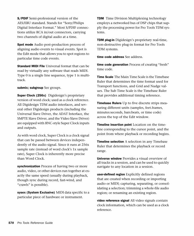
578
S/PDIF Semi-professional version of the AES/EBU standard. Stands for “Sony/Philips Digital Interface Format.” Most S/PDIF connec-tions utilize RCA in/out connectors, carrying two channels of digital audio at a time.
Spot mode Audio post-production process of aligning audio events to visual events. Spot is the Edit mode that allows you to spot regions to particular time code events.
Standard MIDI File Universal format that can be read by virtually any software that reads MIDI. Type 0 is a single line sequence, type 1 is multi-track.
submix; subgroup See groups.
Super Clock (256x) Digidesign’s proprietary version of word clock; used as a clock reference. All Digidesign TDM audio interfaces, and sev-eral other Digidesign products (including the Universal Slave Driver, the ADAT Interface, the SMPTE Slave Driver, and the Video Slave Driver) are equipped with BNC-style Super Clock inputs and outputs.
As with word clock, Super Clock is a clock signal that can be passed between devices indepen-dently of the audio signal. Since it runs at 256x sample rate (instead of word clock’s 1x sample rate), Super Clock is inherently more precise than Word Clock.
synchronization Process of having two or more audio, video, or other devices run together at ex-actly the same speed (usually during playback, though sync during record, fast-wind, and “crawls” is possible).
sysex (System Exclusive) MIDI data specific to a particular piece of hardware or instrument.
Pro Tools Reference Guide
TDM Time Division Multiplexing technology employs a networked bus of DSP chips that sup-ply the processing power for Pro Tools TDM sys-tems.
TDM plug-in Digidesign’s proprietary real-time, non-destructive plug-in format for Pro Tools TDM systems.
time code address See address.
time code generation Process of creating “fresh” time code.
Time Scale The Main Time Scale is the Timebase Ruler that determines the time format used for Transport functions, and Grid and Nudge val-ues. The Sub Time Scale is the Timebase Ruler that provides additional timing reference.
Timebase Rulers Up to five discrete strips mea-suring different units (samples, feet.frames, minutes:seconds, bars:beats, or time code) across the top of the Edit window.
Timeline insertion point Location on the time-line corresponding to the cursor point, and the point from where playback or recording begins.
Timeline selection A selection in any Timebase Ruler that determines the playback or record range.
Universe window Provides a visual overview of all tracks in a session, and can be used to quickly navigate to any location in a session.
user-defined region Explicitly defined regions that are created when recording or importing audio or MIDI; capturing, separating, or consol-idating a selection; trimming a whole-file audio region; or renaming an existing region.
video reference signal All video signals contain clock information, which can be used as a clock reference.
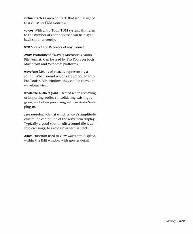
virtual track On-screen track that isn’t assigned to a voice on TDM systems.
voices With a Pro Tools TDM system, this refers to the number of channels that can be played back simultaneously.
VTR Video Tape Recorder of any format.
.WAV Pronounced “wave”; Microsoft’s Audio File Format. Can be read by Pro Tools on both Macintosh and Windows platforms.
waveform Means of visually representing a sound. When sound regions are imported into Pro Tools’s Edit window, they can be viewed in waveform view.
whole-file audio regions Created when recording or importing audio, consolidating existing re-gions, and when processing with an AudioSuite plug-in.
zero crossing Point at which a wave’s amplitude crosses the center line of the waveform display. Typically a good spot to edit a sound file is at zero crossings, to avoid unwanted artifacts.
Zoom Function used to view waveform displays within the Edit window with greater detail.
Glossary 579

580
Pro Tools Reference Guide
Symbols.1 (in surround mixing) 420
Numerics11025 sample rate 40711127 sample rate 40716-bit
Bounce to Disk 40716-bit Optimized Mixer
clipping 567plug-in features 567
1-Band EQ plug-in 51722050 sample rate 40722254 sample rate 40724 FPS 46124-bit
Bounce to Disk 407TDM processing 352
24-Bit Optimized Mixerplug-in capabilities 566
24-bit Optimized Mixerclipping 567
25 FPS (EBU) 46129.97 FPS Drop 46129.97 FPS Non-Drop 460, 4913:2 Pulldown 46230 FPS Drop 46030 FPS Non-Drop 46032-bit, floating 3523-knob panning 4493-Second Peak Hold preference 53844100 sample rate 40748000 sample rate 4074-Band EQ plug-in 517
5.0 paths in 5.1 mixes 4395.1 formats in Pro Tools 4298-bit 407
Aactive 13
tracks 84Active in Background
for MP3 play 406Active in Background option 531ADAT, syncing to 481Add Movie command 526adding
a new playlist 173audio tracks 125Auxiliary Input tracks 332Master Fader tracks 333MIDI tracks 145Sends 339
AIFF file format 402All Notes Off command 308, 523all tracks
hiding 79selecting 201selecting all regions in 197selecting in Timebase Rulers 201showing 79
allocatingDSP 561, 563I/O capacity 568
Amount of Memory for Automation Recording option 543
Assignment viewsends 340
Audio CD Import Options dialog (Macintosh) 99Audio During Fast Forward/Rewind option 190,
538
Index
Index 581
582
audio filesbatch loading with drag & drop 96compacting 259concepts 10default names 116formats 401importing 91locating 105mixed file types 53mixed formats 92
audio format, for session 469audio interfaces 5, 6
input channels 11Other Options 47, 48, 49
audio recordingundoing a take 126
audio regions 168and automation 170fitting to an Edit selection 238stripping silence from 253whole-file 164
Audio Regions Focus 40, 178Audio Regions List 35, 175
displaying file info for audio regions 176dragging from 212finding regions 177sorting 176
Audio Regions List menu 35, 488Auto Rename Selected command 257Clear Selected command 258Compact Selected command 259Display All command 177Export Region Definitions command 98Export Selected As Files command 97Find command 177Rename Selected command 257Selected Unused command 258Show Disk Names option 176Show File Names option 176Show Full Pathnames option 176Sorting option 176Time Stamp Selected command 220
audio tracks 105.1 format 425and Output format 433and surround sessions 432and tempo changes 263bouncing to disk 400channel strips 18
Pro Tools Reference Guide
configuring for recording 125creating a tempo map for 264loop recording 132placing audio in multi-channel tracks 432punch recording 131recording multiple 128signal flow 331Waveform view 28, 165, 168
Audiomedia III 7QuickPunch 156
AudioSuite and dither 353AudioSuite Buffer Size preference 543AudioSuite Dither preferences 543AudioSuite menu 517
DC Offset Removal plug-in 518Delay plug-ins 518Duplicate plug-in 518dynamics plug-ins 517EQ II plug-ins 517Gain plug-in 518Invert plug-in 517Normalize plug-in 518Pitch Shift plug-in 518Reverse plug-in 518Signal Generator plug-in 518Time Compression/Expansion plug-in 518
AudioSuite plug-ins 232audition path 72auditioning
fades 243pre/post-roll 204programs 305selection start/end points 204takes 133
Auto Input Monitoring option 113, 529Auto Regions Fade In/Out Length option 250, 540Auto Rename Selected command 257auto-created regions 164
hiding 257renaming 256
auto-fades 250AutoMatch Indicators 376AutoMatch Time option 375, 543automating
Plug-Ins 380Sends 379switched controls 379tracks 378
automation 369and audio regions 170and Duplicate Track 371and multi-channel pan 453and multiple output assignments 433breakpoints 387buffer size 376capture & apply 395cutting, copying, and pasting 388deleting 382delta (see trim) 372drawing with Pencil 384editing 385editing with Smart Tool 33enabling, suspending 381for grouped tracks 388for hidden tracks 18on multi-channel tracks 387On Stop 393pass-through point 372playlists 173, 370, 377plug-in accuracy in bounce 408relative and absolute 372safing 377smoothing 375snapshot 394special Paste mode 391stepped 386thinning 375, 383To Current or All Enabled 396to start, end, or all 391Trim mode 372trimming 393Write Safe button 360writing 378
Automation Enable window 378, 381Automation Mode Selector 21automation modes
Auto Latch 372Auto Off 371Auto Read 371Auto Touch 372Auto Write 371Trim/Auto Latch 373Trim/Auto Off 372Trim/Auto Read 372Trim/Auto Touch 373Trim/Auto Write 373
Automation Preferences 542AutoMatch Time option 375Degree of Thinning option 375Faders Move During Playback option 374LFEs Follow Groups option 375Memory for Automation Recording option 376Mutes Follow Groups 374Mutes Follow Mix Groups option 83Send Levels Follow Groups option 374Send Mutes Follow Groups 374Smooth and Thin Data After Pass option 374,
383Solos Follow Groups option 374Solos Follow Mix Groups option 83Touch Timeout option 375
Automation Safe Button 360Automation Write Safe button 363Auto-Name Memory Locations While Playing option
273, 541Auto-Name Separated Regions option 210, 541auto-naming
and Strip Silence 254audio files and regions 116QuickPunch regions 157separated regions 210takes 116tracks 116
AutoSave option 539Auto-Spot Regions command 487, 531auto-voiced tracks 21Auxiliary Inputs 347
adding 332and DSP usage 566signal flow 332
Auxiliary Send level, and Master Fader 349Avid Compatibility Mode option 544
and Bounce to Disk 401
Bbank select 16, 302Bar|Beat Markers
and tempo events 266audio with varying tempos 265editing 266from Identify Beat command 264generated with Beat Detective 286moving 266
Bars:Beats Time Scale 185, 549
Index 583
584
bassextension 423management 423
sub content 421redirection 423
Batch Fades dialog 251Beat Detective 279
applications for 280beat triggers 284Collection Mode 290conforming regions 288defining the selection 282detecting transients 283edit smoothing 289generating Bar|Beat Markers 286separating regions 287system requirements 279with multiple tracks 287
Beat Detective window 281beat triggers, editing 284Bi-Phase/Tach 460bit depth, for session 51, 468black burst 491Blocks view 165Bounce options
File Type 507Format 507Import After Bounce 508Resolution 507Sample Rate 507Source 401, 507Use Squeezer 508
Bounce to Disk 401and dither 398and time stamps 400convert during or after 408format 401mono, stereo, interleaved 406sample rate conversion options 407source path 401
Bounce to Disk command 507Bounce to Movie command 502, 525bouncing
to a stereo mix 409to a submix 408to QuickTime movies 502
breakpoints 387Buffer Size 114
Pro Tools Reference Guide
bussingmulti-channel sends 435surround examples 439
Bypass Buttonfor real-time plug-ins 360
bypassing plug-ins 362
CCalculator mode for numeric entry 201Calibration Mode command 112, 532Calibration Reference Level preference 540cancelling record takes 127, 147Capture Region command 209, 512capturing time code 486CDs, importing audio from 98Center% in Output window 452center, surround controls 452centered crossfade 242Change Duration command 318, 521
Change Duration window 318Change Meter command 267, 520
Change Meter window 267Change Tempo command 261, 519
Change Tempo window 262Change Velocity command 316, 520
Change Velocity window 316Channel Delay Indicator 23channel mapping
default path order 74editing 66re-mapping 67
Channel Selector 360for multi-channel plug-ins 436
channel strips 11audio tracks 18MIDI tracks 20
channels inputs 11chasing
controller events 306MIDI notes 306program changes 306
Cinema Stereo 416Classic Numeric Keypad Mode 41, 539Classic, Numeric Keypad Mode 41Clear command 226, 512
Clear Selected command (regions) 258Clear Selection command (movies) 527click 38
configuring 122enabling 121
Click command 522Click Options command 122, 522
Click/Countoff Options dialog 122clicks and pops, avoiding 169clipping 111
and 16-bit Optimized Mixer 567and 24-bit Optimized Mixer 567input sum levels 567
clock, optical and digital sources 367Close Session command 56, 506closing multiple Plug-In windows 361Collection Mode, Beat Detective 290Commands Focus 40Commands Focus button 29Comments View 25, 336comments, entering for tracks 78Compact Selected command 259Compare button 360compatibility
surround formats 422Compatibility Preferences 544comping related takes 135Compress/Expand Edit To Play command 237,
513and multi-channel tracks 238
Conductor button 38Conductor Rulers 184
including in selections 201configuring
click options 122MMC 479Pull Up/Down 473SMPTE 471
conforming QuickTime movies 499connecting
effects units 365external audio devices 365external clock sources 366
Consolidate Selection command 256, 513Continuous Scroll During Playback option 192, 530
and half-screen 192
Continuous Scroll with Playhead option 192, 530and half-screen 192
control surfaces (see MIDI control surfaces)controller events 16, 301
and MIDI regions 172chasing 306editing 302editing with Smart Tool 33inserting 302
Conversion Quality option 99, 407, 500, 541Tweak-head setting 407
Convert .WAV files to AES31/BroadcastWave option 544
Convert After Bounce 408Convert During Bounce 408Convert Plug-In pop-up 360converting session
audio file format 53bit depth 53sampling rate 53
Copy command 227, 511Copy Edit Selection to Timeline command 207,
531Copy Timeline Selection to Edit command 207,
531Copy To Send command 380, 515
Copy To Send dialog 380copying
all automation playlists for a track 228MIDI notes with the Split command 311selections and regions 227track automation to Sends 380track control settings to Sends 346
correlated 436countoff 38, 121CPU Load 376CPU Usage percentage 45Create Fades command 248, 514creating
crossfades 248fade-ins/outs 249groups 87Markers and Memory Locations 272regions 209sessions 50
Crossfade Preference for Pre/Post-Roll option 247, 541
Index 585
586
crossfades 241and dither 353creating with Smart Tool 32equal gain 245equal power 245, 247Fades dialog 242in batches 251linear 247overlap 247pre/post 248removing 248trimming 248types 241with dither 245
Current Cursor Displaylocation 34value 34
current meter 38, 267current tempo 38, 261Current Time option 548custom sample rates 407Cut command 227, 511cutting
automation 389MIDI notes with the Split command 311selections and regions 227
DDAC Muting option 47DAE 9DAE Buffer Size command 49, 534DAT recorder, recording from 158DC Offset Removal plug-in 518default
audition path 72I/O Setup 70output path 72path order 74paths 64
Default Fade Settings 541default meter 122Default Note On Velocity option 296, 544default program change 23, 303Default Settings preference 543default tempo 123, 264Default Thru Instrument option 545
Pro Tools Reference Guide
default track names 116Degree of Thinning option 375, 542Delay plug-ins 518delays (see DSP delays)Delete Fades command 248, 514Delete Selected Groups command 87Delete Selected Tracks command 78, 509deleting
automation 382, 389existing paths 71groups 88in MIDI Event List 327Memory Locations 275MIDI notes 300playlists 174program changes 305sysex events 306tracks 78underlying region data 227unused regions 258
deltatrimming automation 372
destructive editingcompacting audio files 259
Destructive Record mode 119, 130, 529destructive recording 130Digi 001 7
modes and I/O Setup 65punching with footswitch 149, 155QuickPunch 156
Digidesign Audio Engine (see DAE)digital audio 9digital clipping 111digital mastering 410digital signal processing (see DSP)DigiTest 570
as a diagnostic tool 570Direct I/O 570discontiguous selections 197discrete
level control of multi-channel paths 432disk allocation
and cross-platform sessions 118and system volume 118
Disk Allocation command 117, 534Disk Allocation dialog 117
Disk Space Window Shows command 548
Display All command 177Display Auto-Created Regions option 257, 549Display menu 547
Bars:Beats Time Scale 549Disk Space Window Shows command 548Display Auto-Created Regions option 257, 549Display Name In Regions option 168Display Name in Regions option 548Display Time In Regions option 168Display Time in Regions option 548DSP Usage Window Shows option 562Edit Window Shows option 25, 547Feet.Frames Time Scale 549Minutes:Seconds Time Scale 549Mix Window Shows option 17, 547Narrow Mix Window option 85, 547Ruler View Shows option 185, 548Samples Time Scale 549Sends View Shows command 548Show Mix Window command 547System Usage Window Shows command 548Time Code Time Scale 549Transport Window Shows command 547
Display Name In Regions option 168Display Name in Regions option 548Display Preferences 537
Draw Grids in Edit Window option 180Draw Waveforms Rectified option 169Edit Window Color Coding option 85Peak Hold option 24Show Meters in Sends View option 341
Display Time In Regions option 168Display Time in Regions option 548displaying
all regions 177all Rulers 185file info for audio regions 176Meter Ruler 267Original Time Stamps 488region names 168region times 168Tempo Ruler 261User Time Stamps 489
ditherand Bounce to Disk 398and fades 245, 353AudioSuite 353on Master Faders 398resolution and Bounce to Disk 406
Dither Depth option 543Dither Plug-In preference 543divergence
and width 421drawing 452front 451front and rear 451rear 451using 451
Dolby Digital 420Dolby EX 416Dolby Surround 416Draw Grids in Edit Window option 180Draw Waveforms Rectified option 169, 537drum machine style loop recording 150DSP 561
active and inactive items 13allocating 561, 563and Auxiliary Inputs 566and I/O capacity 568and inactive outputs 338and inactive sends 342and Master Faders 568and mixing 562, 563and no output 338and overall resources 13and Send meters 341and TDM Plug-Ins 568I/O and Mixer plug-ins 565monitoring usage 562reclaiming DSP capacity 562
DSP delays 557compensating for 558
DSP Manager 562DSP Usage window 562DTS 416, 420Duplicate command 229, 512Duplicate plug-in 518Duplicate Selected Tracks command 508Duplicate Track
for automation 371duplicating
MIDI note selections 230playlists 173selections and regions 229
Index 587
588
durations, for MIDI notesediting with Change Duration command 318making more legato 319making more staccato 319randomizing 318
dynamic voice allocation 82
EEdit and Timeline selections, unlinked 195edit commands 225
and Edit mode 226clear 226, 227cut 227paste 228
edit cursor 189and scrubbing 192moving to region boundaries 202
Edit Dither Settings preference 543Edit Groups 35
and selections 196Edit Insertion Follows Scrub/Shuttle option 192,
538Edit insertion point
placing regions at 213trimming regions to 216
Edit Markers 196and selection length 199
Edit menu 264Capture Region command 209, 512Clear command 226, 512Compress/Expand Edit To Play command 237,
513Consolidate Selection command 256, 513Copy command 227, 511Copy To Send command 380, 515Create Fades command 248Cut command 227, 511Delete Fades command 248Duplicate command 229, 512Fade To End command 250Fade To Start command 250Fades command 514Heal Separation command 212, 513Identify Beat command 514Identify Sync Point command 217, 489, 513Insert Silence command 255, 514Lock/Unlock Regions command 225, 513
Pro Tools Reference Guide
Merge Paste command 231, 512Mute/Unmute Region command 225, 513Paste command 228, 511Quantize Regions command 224, 513Redo command 511Remove Sync Point command 217Repeat command 230, 512Repeat Paste To Fill Selection command 237,
511Select All command 197, 512Separate Region command 210, 512Shift command 224, 512Strip Silence command 253Thin Automation command 384, 515Trim Automation command 396, 515Trim command 512Trim End To Insertion command 216Trim Start To Insertion command 216Trim To Selection command 211Undo command 174, 511Write Automation command 394, 395, 515
Edit mode buttons 179Edit modes 179
and edit commands 226and placing regions 212Grid 28, 179Shuffle 28, 179Slip 28, 179Spot 28, 179, 485
edit playlists 172Edit selections
auditioning with Playhead enabled 207copied from Timeline selection 207copied to Timeline selection 207sliding in the Ruler 203start, end, and length fields 33
edit smoothing, with Beat Detective 289Edit tools 30Edit window 26
Edit tools 30half-screen 192scrolling from the Ruler 191track controls 27
Edit Window Color Coding option 85, 538Edit Window Default Length option 537Edit Window Follows Bank Selection option 537Edit Window Shows option 25, 547
editingacross multiple tracks 228and Edit modes 179and hidden tracks 18automation 385Bar|Beat Markers 266beat triggers 284breakpoints 387controller events 302during playback 163Grid mode 179in MIDI Event List 326Markers 274Memory Locations 274meter events 268MIDI notes 297MIDI regions 171nondestructive 163non-destructively for audio 170non-destructively for MIDI 172note attributes 300note durations 318note velocities 299, 316program changes 304Shuffle mode 179Slip mode 179Spot mode 179tempo events 262waveforms 169
Editing PreferencesAuto-Name Memory Locations While Playing
option 273Auto-Name Separated Regions option 210Conversion Quality option 99Crossfade Preference for Pre/Post-Roll option
247, 541QuickPunch Crossfade Length option 155Region List Selection Follows Track Selection
option 176, 204Separate Region Operates On All Related
Takes option 135, 210Take Region Lengths That Match option 135Take Region Names That Match Track Names
option 135Track Selection Follows Regions List Selection
option 204effects, printing to disk 397
Enable Automation Parameters Button 360, 363Enable Autosave option 539enabling
automation 381groups 18, 35, 88MIDI input devices 142
encoding and decoding 422Enforce Mac/PC Compatibility option 54, 505EQ II plug-ins 517equal gain crossfades 245equal power crossfades 245, 247Ethernet Controllers page 535Event Edit Area 33
note attributes 300Exit command (Windows) 56, 510Expanded Track Display 167, 387Export MIDI command 103, 509Export Region Definitions command 98Export Selected As Files command 97Export Selected dialog 97Export Session as Text command 100, 509exporting
a session as text 100audio 97audio from regions 97MIDI tracks 103region definitions 98, 489stereo interleaved files 97
extending selections 200to adjacent tracks 201, 202to include adjacent regions 200to Markers and Memory Locations 200to region boundaries 200
Extensions 571external clock sources 366
Ffactory settings 71Fade To End command 250, 514Fade To Start command 250, 514fade-in shapes 246fade-out shapes 244Faders Move During Playback option 374, 542fades 249
and dither options 353auto-fades 250
Index 589
590
creating 249creating with Smart Tool 32in batches 251with dither 245
Fades command 514Fades dialog 242
In Shape 246Link option 245Out Shape 244Use Dither option 245
Fast Forwardincrementally 190locating with 190
Fast Forward button 36Feet.Frames and QuickTime offset 498Feet.Frames command 536Feet.Frames Time Scale 186, 549file formats (audio) 401
AIFF 402MP3 404QuickTime 402RealAudio 402SND resource 402Sound Designer II 401WAV 402
file management 105File menu
Bounce to Disk command 507Close Session command 56, 506Delete Selected Tracks command 78, 509Duplicate Selected Tracks command 508Exit command (Windows) 56, 510Export MIDI command 103, 509Export Session as Text command 509Get Info command 510Group Selected Tracks command 87, 508Import Audio to Track command 93, 509Import MIDI to Track command 102, 509Import Tracks command 510Make Selected Tracks Inactive command 508New Session command 50, 505New Track command 125, 145, 508Open Session command 51, 506Quit command (Macintosh) 56, 510Rename Selected Tracks command 508Revert to Saved command 52, 507Save Session As command 52, 506Save Session command 52, 506Save Session Copy In command 54, 108, 506
Pro Tools Reference Guide
Split Selected Tracks Into Mono command 231, 508
Film 416film speed 462filtering in bass management 423final mixdown 409Find command 177finding regions 177Format (in Bounce to Disk) 406formats
supported multi-channel 416freewheeling time code 470Front Divergence 451Front/Rear Divergence 451
GGain plug-in 518generating time code 469, 474Get Info command 510Global MIDI Playback Offset option 307, 544Go to End button 36Grabber tool 30
editing breakpoints with 385Object Grabber 198selecting MIDI notes with 297Separation Grabber 211
Grid mode 28, 179and moving regions 220Draw Grids in Edit Window option 180Grid Value pop-up menu 179Regions/Markers option 180setting the Grid value 221
grid panners in Mix and Edit 443Grid value 34, 221Group Selected Tracks command 87, 508groups
and automation editing 388and hidden tracks 18and LFEs 375and pan 453and selecting tracks 18and send level, mute 374changing members 88creating 87deleting 88Edit Groups 35enabling 18, 35, 88
Mix Groups 18renaming 88unlinking Edit and Mix Groups 88
Groups List 86Groups List Focus 40Groups List focus 89Groups pop-up menu 87
Delete Selected Groups command 87Display command 87New Group command 87Suspend All Groups command 87
HH/W Buffer Size 114half-screen 192half-speed playback 159half-speed recording 159hard drives
and QuickTime movies 495recording to system volume 118Round Robin Allocation 117
hardwareupdating I/O Setup after changing 65
Hardware BufferCPU Usage Percentage 45
Hardware command 46, 47, 533hardware I/O Inserts 355hardware I/O Sends 339Hardware Setup dialog 45, 47
Buffer Size 114DAC Muting option 47hardware buffer size 45
Heal Separation command 212, 513hidden tracks
and group edits 18and groups 18and selections 196
hidingall tracks 79auto-created regions 257tracks 79
Highest Priority Playback option 495, 526Horizontal Zoom buttons 180host processing 45host processor 9
II/O capacity
allocating 568and DSP usage 568
I/O Labels (see I/O Setup)I/O Settings 71I/O Setup
and surround sessions 426default settings 70displaying unavailable I/O 70factory settings files 71import and export 71importing for surround 428initializing 67last used 71reset paths 65settings files 70Stereo Mix preset 71surround mix examples 439surround mix settings file 72
I/O Setup command 535I/O View 22Identify Beat command 264, 514
Identify Beat dialog 265Identify Sync Point command 217, 489, 513Import Audio dialog 93Import Audio From Current Movie command 501,
525Import Audio From Other Movie command 98, 525Import Audio to Track command 93, 509Import MIDI command 103Import MIDI to Track command 102, 509Import Movie command 496, 525
Import Movie dialog 496Import Tracks command 94, 510importing
and converting audio 92audio 91audio and Conversion Quality 99audio from CDs 98audio from QuickTime movies 501audio into a session 91audio with drag & drop 96MIDI tracks 102multi-channel I/O Settings 428QuickTime movies 496tracks from other sessions 94
Index 591
592
inactive 13Master Faders and assignments 334paths 68paths, global 68sends 342track path assignments 68tracks 84
Infinite Peak Hold preference 538in-place auditioning 73input connections 11, 111
and digital sources 158Input Devices command 142, 523
Input Devices dialog 142Input Filter command 143, 523
MIDI Input Filter dialog 143, 323input levels 111Input Only Monitoring option 114, 530Input Quantize command 144, 522
Input Quantize window 144Input Selector 22Insert controls 25Insert Position Selector 359Insert Silence command 255, 514
and Shuffle Mode 255and Slip Mode 255
insertingcontroller events 302in MIDI Event List 324meter events 267MIDI notes 295program changes 304tempo events 261
Inserts 355as a shared bus 356for hardware I/O 355for plug-ins 355labeling 364on single tracks 356post-fader on Master Faders 333, 356shared within a submix 348
Inserts View 25Interleaved 406
Bounce to Disk 406Inverse linked panning 344Invert plug-in 517
Pro Tools Reference Guide
JJam Sync 470
KKey Input Selector 360Keyboard Focus 39
Audio Regions Focus 40, 178Commands Focus 40Commands focus 29Groups List Focus 40Groups List focus 89MIDI Regions Focus 40, 178
keyboard Input for plug-in parameters 363keyboard shortcuts 363
global key commands 39numeric entry 201recording 126
Llabeling
Inserts and Sends 364paths 64
Last Used 71Latch Record Enable Buttons option 113, 538Latch Solo Buttons option 539latency for recording and monitoring 114LCRS
path examples 428length, for selections 199level faders
sends 25tracks 24
Level Indicator 23level meters
clearing 24for audio tracks 24for MIDI tracks 24for Sends 25
Levels of Undo option 542LFE
and groups 375enable in plug-ins 451example sub-path 439examples of discrete versus contribution 440faders 451plug-in enable 360
LFE Enable Button 360
LFEs Follow Groups option 375, 542Librarian menu 359Limit To option 540linear crossfades 247Link Edit and Timeline Selection option 195, 531Link Enable buttons 360
and multi-channel 436Link Mix and Edit Group Enables option 539Link Record and Play Faders option 114Link Selection button 29, 195linking
inverse panning 344multi-mono plug-ins 436plug-in controls 362stereo panners 343
Local Control 16, 143locating
with Fast Forward/Rewind 190with Location Indicators 191
Location Indicators 34, 190locating with 191
locations, for MIDI notesdragging 298quantizing 314randomizing 314, 315
Lock/Unlock Regions command 225, 513locking regions 225Loop Playback option 205, 530
and audio recording 133and Auto Touch mode 378
loop points 135and Playback Markers 136recalling with Memory Location 138
Loop Record mode 120, 133, 529loop recording
and pre/post-roll 132audio 132MIDI 150
drum machine style 150multiple takes 151
looping selections 205loops and reverb, delay 399Low Latency Monitoring option 115Lt Rt 420LTC (Linear Time Code) 459
MMachine Chases Memory Location option 480,
540Machine Control option 540Machine Control page 535Machine Cues Intelligently option 540Machine Follows Edit Insertion/Scrub option 480,
540main paths 61Main Time Scale 186, 473Make Selected Tracks Inactive command 508managing regions 256Manual Tempo mode 38, 123mapping paths in I/O Setup 66Markers 270
creating 272creating on the fly 273deleting 275editing 274extending selections to 200moving 275sorting 277tick-based and sample-based 271viewing options 276
Master Fadersadding 333and DSP usage 568as master send level control 349inactive 334inserts 356meters pre/post fader 334multi-channel 435paths 337post-fader inserts 333signal flow 333
Master Link Button 360in multi-channel plug-ins 436
master view for tracks 166, 389mastering
digitally 410to disk 409
Matching Start Time Takes List preference 541matrix 419measures
partial 269renumbering 269
Medium Priority Playback option 495, 526
Index 593
594
Memory for Automation Recording option 376Memory Location dialog 270Memory Locations 270, 271
creating 272creating on the fly 273deleting 275deleting all 275editing 274extending selections to 200Markers 270recalling 274renaming 274Selection Memory Locations 271storing punch/loop points 138
Memory Locations window 276view filter 277viewing options for Markers 276
Merge mode (see MIDI Merge mode)Merge Paste command 231, 512meter
current 267default 122
meter events 267editing 268inserting 267
Meter Rulerdisplaying 267extending an Edit selection to 268
meterssends view 341SurroundScope plug-in 453
MIDI 15and signal paths 16audio input to Pro Tools 347common misconceptions 16tracks 10
MIDI Beat Clock command 485, 522MIDI channels 15
assigning 82MIDI clips and Regions List 176MIDI control surfaces 15, 352MIDI controller devices 15, 141
Local Control 16, 143MIDI Controllers page 535MIDI Device/Channel Selector 23, 82MIDI devices 15
Pro Tools Reference Guide
MIDI Event List 321deleting events 327editing events 326inserting events 324navigating in 322Options menu 328selecting events 326View Filter 323
MIDI Event List options 328View Filter command 323
MIDI files (see Standard MIDI Files)MIDI Input Selector 148MIDI Machine Control (MMC) 479
configuring in Pro Tools 479controlling external devices with 479remote track arming 481syncing to a sequencer with 483syncing to an ADAT 481
MIDI menuAll Notes Off command 308, 523Change Duration command 318, 521Change Meter command 267, 520Change Tempo command 261, 519Change Velocity command 316, 520Click Options command 122, 522Input Devices command 142, 523Input Filter command 143, 523Input Quantize command 144, 522MIDI Beat Clock command 485, 522MIDI Thru option 143, 523Quantize command 311, 520Renumber Bars command 269, 520Select Notes command 310, 521Split Notes command 311, 521Transpose command 319, 521
MIDI Merge mode 38, 120, 145MIDI Note Display option 545MIDI notes
attributes for 33, 300chasing 306deleting 300duplicating selected 230editing 297
durations 318pitch 297velocities 299, 316
inserting 295lengths in ticks 187moving 298
quantizing 311selecting 297, 310splitting 311transposing 297, 319trimming start/end points 298
MIDI offsets 307MIDI Operations window 309
parameter options 309MIDI Output Selector 145MIDI Preferences 544
Default Note On Velocity option 296Global MIDI Playback Offset option 307Pencil Tool Resolution When Drawing Controller
Data option 302, 385, 544MIDI recording 141
cancelling takes 147enabling input devices 142Input Filter 143Merge/Replace mode 145monitoring with MIDI Thru 142quantizing on input 144System Exclusive data 152undoing a take 147Wait for Note 144
MIDI regions 170and controller events 172and Merge Paste command 231and punch recording 149guidelines for editing 171
MIDI Regions Focus 40, 178MIDI Regions List 35, 175
and MIDI clips 176dragging from 212finding regions 177sorting 176
MIDI Regions List menu 35Auto Rename Selected command 257Clear Selected command 258Display All command 177Find command 177Import MIDI command 103Rename Selected command 257Select Unused command 258Sorting option 176Time Stamp Selected command 220, 488
MIDI Replace mode 38, 120, 145MIDI Thru option 143, 523
MIDI tracksand MIDI offsets 307and tempo changes 263assigning to multiple channels 146channel strips 20configuring for recording 145default program change 303exporting 103loop recording 150Merge Paste command 231note chasing 306Notes view 165, 170punch recording 148punching on the fly 149record enabling 112recording 141, 145Regions view 165, 171selecting a pitch range in 310Sysex view 305Velocity view 299
Minimum Sync Delay option 481Minutes:Seconds Time Scale 185, 549mix busses 339Mix Groups 18Mix window 17, 19
track controls 20track width 85
Mix Window Follows Bank Selection option 537Mix Window Shows option 17, 547mixed file types 53, 92mixer channels 11Mixer plug-ins 563mixing 415
surround formats 416mixing and DSP usage 562, 563mixing down to stereo 409MMC (see MIDI Machine Control)monitoring
during punch recording 131MIDI recording with MIDI Thru 142record and playback levels 114
monitoring latency 114monitoring modes 113
Auto Input Monitoring 113Input Only Monitoring 114
Index 595
596
monoBounce to Disk 406format 416paths 64
Mono In/Stereo Out 356Movie menu
Add Movie command 526Bounce to Movie command 502, 525Clear Selection command 527Highest Priority Playback option 495, 526Import Audio From Current Movie command
501, 525Import Audio From Other Movie command 98,
525Import Movie command 496, 525Medium Priority Playback option 495, 526Movie Online command 526New Movie Track command 526Normal Priority Playback option 495, 526Set Movie Sync Offset command 498, 526Show Movie Window command 497Undo Add Movie command 527Window Aspect Ratio command 526
Movie Online command 526Movie Tracks 496
scrubbing 497setting sync point 499
Movie window 497movies (see QuickTime movies)moving
Bar|Beat Markers 266Markers 275MIDI notes 298program changes 304sysex events 305
MP3 and Digidesign hardware 406MP3 file format 404MTC (MIDI Time Code) 459
outputting 469multi-channel plug-ins 356, 436multi-channel regions 164multi-channel tracks 128
and automation 387dragging regions to 232names for 117replacing regions in 237signal routing 431splitting 231
Pro Tools Reference Guide
multi-monoplug-in channel selector 436plug-ins 356, 435
Multiple mono 406multiple tracks
and Beat Detective 287audition takes 134editing across 228extending selections to 201, 202fitting audio regions to Edit selection 238nudging regions in 222pasting to 229selecting 201separating regions on 210shuffling regions on 218
MultiShell 568Mute automation 386Mute button 21, 84Mute Frees Assigned Voice option 84, 531Mute/Unmute Region command 225, 513Mutes Follow Groups option 374, 542Mutes Follow Mix Groups option 83muting
regions 225tracks 84
NNarrow Mix Window option 85, 547network connections 571New Group command 87New Movie Track command 526New Session command 50, 505
and last used 71New Track command 125, 145, 508
New Track dialog 125No Auto-Scrolling option 191, 530No Output 338
by deleting paths 66No Peak Hold preference 538nondestructive editing 163
for audio 170for MIDI 172
Nondestructive Record mode 119nondestructive recording 129
recording to a new playlist 130with QuickPunch 155
Normal Priority Playback option 495, 526Normalize plug-in 518Note Chasing option 306notes (see MIDI notes)Notes view 165, 170
mini-keyboard 170scrolling up or down 171
Nudge value 34, 222trimming regions by 217
nudging 221by next Nudge Value 223multiple regions 222region contents 223selection range 199selection start/end points 199selections and regions 222setting the Nudge value 222
numeric entryCalculator mode 201shortcuts 201
Numeric Keypad Mode 539Numeric Keypad modes 41, 539
Classic 41Shuttle 42, 194Transport 41
OObject Grabber 198
and Edit Groups 198Object selections 197offline regions 164OMS MIDI Setup command 536OMS Names command 536OMS patch names 303OMS Studio Setup command 536On Stop 393Online button 36Online option 474, 530, 539online recording 474on-the-fly punch recording
MIDI tracks 149QuickPunch 120, 155
Open Ended Record Allocation option 118, 539Open Session command 51, 506opening multiple Plug-In windows 361
Operation Preferences 538Audio During Fast Forward/Rewind option 190Auto Regions Fade In/Out Length option 250Edit Insertion Follows Scrub/Shuttle option
192Latch Record Enable Buttons option 113Link Record and Play Faders option 114Machine Chases Memory Location option 480Machine Follows Edit Insertion/Scrub option
480Open Ended Record Allocation option 118Record Online option 474Use F11 for Wait for Note 144
Operations menuActive in Background option 531Auto Input Monitoring option 113, 529Auto-Spot Regions command 487, 531Calibration Mode command 112, 532Copy Edit Selection to Timeline command 207,
531Copy Timeline Selection to Edit command 207,
531Destructive Record mode 130, 529Input Only Monitoring option 114, 530Link Edit and Timeline Selection option 195,
531Loop Playback option 205, 530Loop Record mode 133, 529Low Latency Monitoring option 115Mute Frees Assigned Voice option 84, 531Online option 474, 530Play Edit Selection command 207, 531Play Timeline Selection command 207, 531Pre/Post Roll Playback command 138, 530Pre/Post-Fader Metering option 24Pre-Fader Metering command 531QuickPunch mode 529Scroll Options command 530Scrolling Options 191
Opticalas Digi 001 clock source 367
Original Time Stamp 220, 488, 548Other Options dialog 47, 48, 49Output Options
Conversion Quality option 407File Format 401Sample Rate 407Use Squeezer option 408
Output Selector 22
Index 597
598
Output window 24outputs
default 5.1 paths and sub-paths 427format and tracks 433to multi-channel paths 434
overlap crossfades 247overlapping paths 67
PPage Scroll During Playback option 191, 530Pan automation 386Pan Indicator 23Pan Slider 23panning
3-knob 449and groups 453automation and groups 388fine-adjust mode 449grids 443guidelines 438linked stereo 343multi-channel automation playlists 453take over in grid 449trajectory 450X/Y mode 448
parallel mixing 433partial measures 269pass-through point 372Paste command 228, 511pasting
automation 391between automation playlists 228multiple data types 229selections and regions 228to multiple tracks 229with Merge Paste command (MIDI) 231with Repeat Paste To Fill Selection command
237paths
active and inactive 68applying 67audition 72basics 59creating and editing 63creating multi-channel 428default mono and stereo 64default order 74
Pro Tools Reference Guide
default output 72delete existing 71deleting 66for surround 437last used 71main 61mapping 66mono versus stereo 64multi-channel example 67naming 64overlapping 67reset using Default 65Stereo Mix preset 71sub-path surround examples 439
PCI Load 376Peak Hold option 24, 538Peak Indicator 23Pencil tool 31
as Eraser 301drawing automation with 384editing breakpoints with 386inserting MIDI notes with 295repairing waveforms with 232resolution for inserted controller events 302shapes 384
Pencil Tool Resolution When Drawing Controller Data option 302, 385, 544
Peripherals command 534Ethernet Controllers page 535Machine Control page 535MIDI Controllers page 535Synchronization page 534
Phase Invert button 360Pitch Shift plug-in 518pitch, for MIDI notes
transposing with Grabber 297transposing with Transpose command 319
Play button 36Play Edit Selection command 207, 531Play MIDI Notes When Editing option 544Play Timeline Selection command 207, 531playback and Scrolling Options 191playback cursor 189Playback Engine 10
changing 48Playback Engine command 48, 533

Playback Markers 136, 195and Edit selections 196and selection length 199and Timeline selections 206
Playhead 192, 530and Edit selections 207and Timeline selections 207moving to region boundaries 208
playingand on-the-fly selections 197at half-speed 159Edit selections with Playhead enabled 207from a track point 189selections 204Timeline selections with Playhead enabled 207tracks 189
Playlist Selector 27playlists 11, 172
adding new 173and multi-channel tracks 387and nondestructive MIDI editing 172assigning 173automation playlists 173, 370, 377deleting 174duplicating 173edit playlists 172recalling 173recording to new 130renaming 173setting pre/post-roll in 137
plug-in controls, linking 362plug-in inserts 355plug-in parameters
editing 363Plug-In Selector
for real-time plug-ins 360Plug-In Settings menu 359Plug-In window
closing multiple windows 361opening multiple windows 361
Plug-Insand surround mixing 435automating 380automation accuracy in bounce 408bypassing from window 362Channel Selector for multi-mono 436for surround 436
linking 436linking and unlinking 362mixers 566mono-to-stereo 356multi-channel 356multi-mono 356, 435
positional reference 458post crossfades 242, 248pre crossfades 242, 248Pre/Post Roll Playback command 138, 530Pre/Post-Fader Inserts 356Pre/Post-Fader Metering option 24pre/post-roll
and loop recording 132and punch recording 131and recording 137auditioning 204setting 137
Pre/Post-Roll Flags 138, 195Pre-Fader Metering command 531Preferences command 537Pro Tools 24 systems 5
auto-fades 250file management 105
Pro Tools LE 7Pro Tools MIX systems 5
24-bit input and output 410auto-fades 250file management 105pre/post-roll 137QuickPunch 156
Pro Tools TDM 6processing bandwidth 376Processing Preferences 543ProControl, meter configuration 430Program Change window 303program changes 15, 302
and bank select 302auditioning 305chasing 306default, for MIDI tracks 303deleting 305editing 304inserting 304moving 304patch names 303
ProLogic 416
Index 599
600
Pull Up/Down 4633:2 Pulldown 462configuring 473
Punch In Frame Offset preference 540Punch Out Frame Offset preference 540punch points 135
and Playback Markers 136recalling with Memory Location 138
punch recordingand monitoring 131and pre/post-roll 131audio 131MIDI 148MIDI on the fly 149
QQuantize command 311, 520
experimenting with 315Quantize window 312
Quantize Regions command 224, 513and Grid value 221
Quantize window 312Quantize Grid 313Quantize Options 313What to Quantize 312
quantizingMIDI notes 311
attacks vs. releases 312MIDI on input 144regions 224
QuickPunch 120, 155, 529crossfades 155non-TDM systems 156region/take numbering 157TDM systems 156
QuickPunch Crossfade Length option 155, 542QuickTime file format 402QuickTime movies 493, 525
bouncing to 502conforming 494, 499frame length 495importing 496importing audio from 501offset in Feet.Frames 498offsetting 498optimizing for playback 497
Pro Tools Reference Guide
playback quality 495requirements 495setting start time 498spotting 499
Quit command (Macintosh) 56, 510
Rrandomizing
note durations 318note locations 314note velocities 317
RealAudio file format 402real-time editing 163Recall Original Track Selections preference 541Recompute Invalid Overviews preference 537Record button 37, 119Record Enable button 20record enabling tracks 112record modes 119
and MIDI 120Destructive Record mode 119Loop Record mode 120Nondestructive Record mode 119QuickPunch 120switching with Record button 119
Record Online at Insertion/Selection preference 539
Record Online at Time Code (or ADAT) Lock preference 539
Record Online option 474Record Pause mode 129Record Safe mode 20, 113recording 128
a MIDI track 145a mono audio track 125a stereo audio track 127a submix to disk 399additional takes 129at half-speed 159bouncing to disk 400cancelling takes 127destructively 130from a digital source 158from Record Pause mode 129keyboard shortcuts 126monitoring latency 114
multi-channel tracks 128multiple audio tracks 128non-destructively 9, 129non-linear 9online 474stereo tracks 127System Exclusive data 152to a new playlist 130to the system volume 118with a countoff 121with pre/post-roll 137with Round Robin Allocation 117with the click 121
Red Book Audio CDs 502Redo command 511region boundaries
extending selections to 200moving edit cursor to 202moving Playhead to 208
region definitions 98, 489Region List Selection Follows Track Selection
option 176, 204, 541regions 11
aligning to region start points 214auto-created 164auto-naming parameters 257auto-spotting 487capturing 209clearing 226conforming with Beat Detective 288consolidating 256copying 227creating 209crossfading between 248cutting 227default names 116deleting underlying 227displaying all 177displaying names 168displaying times 168dragging from Regions List 212dragging to multi-channel tracks 232duplicating 229exporting as audio files 97extending selections to include 200finding 177healing separations 212
hiding auto-created 257inserting silence into 255locking 225managing 256moving in Grid mode 221multi-channel 164muting 225nudging 222offline 164Original Time Stamp 220pasting 228placing at Edit insertion point 213placing in tracks 212quantizing 224removing unused 258renaming 256repeating 230replacing 235selecting 196selecting all in a track 197separating 210separating with Beat Detective 287separating with Separation Grabber 211shifting 224shuffling 218
on multiple tracks 218sliding 217slipping 219sorting 176spotting 219, 487spotting to movies 500sync points 217, 489time stamping 488trimming by Nudge Value 217trimming start/end points 215trimming to Edit insertion point 216trimming unwanted data from 211User Time Stamp 220user-defined 164, 256, 258whole-file audio regions 164
Regions view 165, 171related takes 134
and Separate Region command 135preferences for 135
Remote Mode option 540remote track arming 481Remove Sync Point command 217
Index 601
602
removingcrossfades 248Sends 339sync points 490
Rename Selected command 257Rename Selected Tracks command 508renaming
auto-created regions 256groups 88Memory Locations 274playlists 173regions 256tracks 116
Renumber Bars command 269, 520Repeat command 230, 512Repeat Paste To Fill Selection command 237, 511repeating selections and regions 230Replace modeReplace Regions command 235
and multi-channel tracks 237Replace Regions dialog 235
reset paths 65resolving sync 491Return to Zero button 36Reverse plug-in 518Revert to Saved command 52, 507Rewind
incrementally 190locating with 190
Rewind button 36Round Robin Allocation 117RTAS processing 45Ruler View Shows option 185, 548Rulers
changing display order 185Conductor Rulers 184displaying all 185scrolling in 191Timebase Rulers 184zooming in 182
Ssafing automation 377sample delays (see DSP delays)sample rate conversion quality 99, 500
Pro Tools Reference Guide
sample rate formats 407custom 407
Samples Time Scale 186, 549Save Session As command 52, 506Save Session command 52, 506Save Session Copy In command 53, 54, 108, 506
Items To Copy 507All Audio Files 507Movie/Video Files 507Session Plug-In Settings Folder 507
saving a copy of a session 53scaling note velocities 299, 317screen savers 571Scroll After Playback option 191, 530Scroll Options command 530scrolling
in the Ruler 191Notes view up or down 171
Scrub Trimmer 216Scrubber tool 31, 192
in Shuttle mode 193selecting with 202
scrubbing 192a single audio track 193and edit cursor 192in Shuttle Lock mode 194Movie Tracks 497on two audio tracks 193playback speed and direction 193resolution 193with Scrub Trimmer 216with the Selector 193
SDDS 416Select All command 197, 512Select Notes command 310, 521
Select Notes window 310Select Unused Regions command 258selecting
a pitch range of notes 310across multiple tracks 201all regions in a track 197all regions in all tracks 197discontiguous regions 197during playback 197grouped tracks 18, 35in MIDI Event List 326
MIDI notes 297, 310notes in a chord 311on all tracks 201regions 196track material 196with Scrubber 202with Selection Indicators 200
Selection Indicators 33, 200and numeric entry shortcuts 201making selections with 200
Selection Memory Location 271moving stored selection 275
selectionsand Bounce to Disk 400and Edit Groups 196and hidden tracks 196and Playback Markers 196auditioning start/end points 204changing length of 199clearing 226consolidating 256copying 227cutting 227discontiguous 197duplicating 229extending 200extending to the Meter Ruler 268extending to the Tempo Ruler 263, 276including Conductor Rulers 201looping 205moving to adjacent tracks 202moving to the next/previous region 203nudging 199, 222nudging start/end points 199Object 197on-the-fly 197pasting 228playing 204removing a track from 202repeating 230shifting 224storing with Memory Locations 271useful techniques 202
Selector tool 30scrubbing with 193selecting MIDI notes with 297
Send controls 25Send Level faders 25
Send Level meters 25Send Levels Follow Groups option 374, 542Send mute 25Send Mutes Follow Groups option 374, 542Send pan 25Sends 338
adding 339and groups 374and multi-channel mixing 434assignment view 340automating 379copying track automation to 380displaying controls for 25, 341for hardware I/O 339for mix busses 339labeling 364mono or stereo 339multi-channel 434removing 339
Sends Default to -INF preference 538Sends View 25Sends View Shows command 548Separate Region command 210, 512
and multiple tracks 210and related takes 135
Separate Region Operates On All Related Takes option 135, 210, 542
Separation Grabber 211Session Setup window 468
Current TC 490session templates 55sessions 10
audio format 469bit depth 51, 468closing 56creating 50creating for surround mixing 426default tempo 264frame rate 469mixed audio formats 53opening 51sample rate 468saving 52start frame 469
Set Movie Sync Offset command 498, 526settings files
import and export 71
Index 603
604
Setups menuDAE Buffer Size command 534Disk Allocation command 117, 534Feet.Frames command 536Feet.Frames Time Scale 186Hardware command 46, 47, 533I/O Setup command 535OMS MIDI Setup command 536OMS Names command 536OMS Studio Setup command 536Peripherals command 534Playback Engine command 48, 533Preferences command 537
Shift command 224, 512Shift dialog 224
shortcuts for keyboard input 363Show Automation Enable command 554Show Beat Detective command 554Show Big Counter command 553Show Disk Names option 176Show Disk Space command 555Show Edit Window command 547Show File Names option 176Show Full Pathnames option 176Show Machine Track Arm command 554Show Memory Locations command 554Show Meters in Sends View option 341Show Meters in Sends View preference 537Show MIDI Event List command 552Show MIDI Operations command 309, 552Show MIDI Track Offsets command 553Show Mix Window command 547Show Movie Window command 497, 555Show Session Setup command 553Show Strip Silence command 555Show System Usage command 555Show Tempo/Meter command 551Show Transport command 553Show Universe command 554Show/Hide Tracks list 17Shuffle mode 28, 179
and locked regions 225and moving regions 218
Shuttle Lock mode 194Shuttle, Numeric Keypad mode 42, 194, 539sibilants 517
Pro Tools Reference Guide
side chain processing 360signal flow
Audio Tracks 331Auxiliary Inputs 332Master Faders 333
Signal Generator plug-in 518signal routing
and default path order 74basics for surround 434example 12surround examples 440
sliding regions 217Slip mode 28, 179
and moving regions 219Smart Tool 31, 32
and audio tracks 32and MIDI tracks 32and multi-channel tracks 33creating crossfades with 32creating fades with 32editing automation with 33editing controller events with 33
Smooth and Thin Data After Pass option 374, 383, 542
smoothing automation 375SMPTE
configuration 471frame formats 460start frame for session 469
SMPTE Slave Driver (SSD) 468generating time code with 474
SMPTE/ITU 416snapshot automation 394, 515
adding to empty automation playlists 394and trim values 396writing over existing automation 395
SND resource file format 402Solo button 20, 83Solo Safe mode 21, 83soloing
tracks 83tracks in a submix 349
Solos Follow Groups option 374, 542Solos Follow Mix Groups option 83sorting
Markers 277regions 176
Sorting option 176
Sound Designer II file format 401Source Path 401speakers
layouts 416suggested 5.1 placement 418surround calibration 419surround placement 418
Split Notes command 311, 521Split Notes dialog 311
Split Selected Tracks Into Mono command 231, 508
splitting stereo and multi-channel tracks 231Spot dialog 219, 486
Use Subframes option 486, 488User Time Stamp button 488
Spot mode 28, 179, 485and moving regions 219trimming regions in 488
spottingauto-spotting 487QuickTime movies 499regions 219, 485, 487
Standard MIDI Files 102exporting 103importing 102Type 0 102Type 1 102
Standard Trimmer 215start frame, for sessions 469stems
surround examples 440stepped control automation 386stereo format 416stereo interleaved files, exporting 97Stereo Mix
I/O Setup factory preset 71stereo tracks
dragging regions to 232names for 117recording 127replacing regions in 237splitting 231
Stop button 36Strip Silence command 253
and region naming 254Strip Silence window 253stuck notes 308
subcontent 421with bass management 423
Sub Time Scale 186, 473subframes 486submixes
applying an Insert to 348bouncing to 408bouncing to disk 399soloing tracks in 349
sub-pathsexamples for surround 437
Support Background Record Applications preference 538
surroundand sends 434basic signal routing 434bass management 423center percentage (%) 452concepts 415configuring Pro Tools and sessions 426delivery formats 422discrete level, solo, mute 432divergence basics 421encoding and decoding 422example 5.1 paths 429formats 415importing I/O Settings 428Lt Rt 420mix compatibility 422mixer specifications 566mixing concepts 422mixing formats 416pan playlists and automation 453panning grids 443Pro Tools formats 416settings files 426speaker arrangements 416terminology 419using paths 437using sub-paths, examples 437
Surround Mixerplug-in features 566specifications 566
SurroundScope 453Suspend All Groups command 87suspending automation 381swing 313, 315
Index 605
606
sync 4573:2 Pulldown 462and film 461Bi-Phase/Tach 460black burst 491film speed vs. video speed 462guide tracks 462LTC 459MIDI Beat Clock 485MMC 479options 467positional reference 458Pull Up/Down 463resolving 491SMPTE frame formats 460time code 458troubleshooting 490VITC 459
Sync Mode 469for digital inserts 365
Sync Offset 470sync points 489
for QuickTime movie 499for regions 217from Beat Detective 289identifying 217, 489
Synchronization page 534syncing to a sequencer
Macintosh 476Windows 478with MMC 483
syncing to an ADAT 481Sysex view 305System Exclusive data 16, 305
and MIDI Thru 142deleting 306moving 305recording 152
System Load 376System Usage 376System Usage Window Shows command 548
TTab to Transients button 29, 203take over (surround pan) 449Take Region Lengths That Match option 135, 542Take Region Names That Match Track Names
option 135, 541
Pro Tools Reference Guide
takesauditioning 133auditioning from Takes List 134default names 116numbering for QuickPunch 157recording additional 129
Takes List pop-up menu 134and multiple tracks 134
tapping in the tempo 124Target Button 360TC/E Plug-In preference 543TDM 561TDM Mixer Plug-Ins 566
switching 566TDM Plug-Ins
and DSP usage 568MultiShell 568
TDM systems 5audio interfaces 6pre/post-roll 137QuickPunch 156voice and track limits 6
technical supportsuggestions 571
tempocurrent 261default 123, 264effects on Markers and Memory Locations 271effects on MIDI and audio 263Manual Tempo mode 123tapping in 124
tempo events 261and Bar|Beat Markers 266editing 262inserting 261
tempo mapfrom Identify Beat command 264
Tempo Rulerdisplaying 261extending an Edit selection to 263, 276
test 408Thin Automation command 384, 515thinning automation 375, 383tick-based and sample-based 271tick-based timing 187time code 458
and Jam Sync 470capturing 486
freewheeling 470generating 469, 474
Time Code Time Scale 186, 549Time Compression/Expansion plug-in 518Time Scale 185
Main 186, 473Sub 186, 473
time stamp 548Time Stamp Selected command 134, 220, 488time stamps and Bounce to Disk 400Time Trimmer 238Timebase Rulers 184
and selecting on all tracks 201and Timeline selections 206Edit Markers 196Playback Markers 195Pre/Post-Roll Flags 195sliding Edit selections 203sliding Timeline selections 207
Timeline Insertion Follows Playback option 538Timeline selections 206
and Playback Markers 206auditioning with Playhead enabled 207copied from Edit selection 207copied to Edit selection 207in Timebase Rulers 206sliding in the Ruler 207start, end, and length fields 37
To All Enabled Parameterswriting automation 396
To Current Parameterwriting automation 396
togglingTrack View 166zoom level 182
tools 30Touch Timeout option 375, 543track controls
Edit window 27Mix window 20
track data 164Track Height 27, 166track layout
default path order 74track level faders 24track level meters 24
Track Name/Comments dialog 77, 116Track Selection Follows Regions List Selection
option 204, 541Track Selector 359Track View 28, 164
Blocks 165Expanded Track Display 167, 387master view 389Notes 165, 170Regions 165, 171Sysex 305toggling 166Velocity 299Waveform 28, 165, 168
Track View Toggle 166track width 85tracks
5.1 format track layout 432adding to selection 201, 202and Record Safe mode 113and surround 431appending new material to end of 130auto-voiced 21color coding 85concepts 10deleting 78entering comments 78grouping 85hiding 79importing 94locating with Fast Forward/Rewind 190making inactive/active 84master view 166, 389moving selections between 202muting 84names 24, 116placing regions in 212playback priority 81playing 189record enabling 112removing from a selection 202selecting across multiple 201selecting all regions in 197selecting all regions in all tracks 197selecting material in 196selecting on all 201soloing 83Track Height 27, 166
Index 607
608
Track View 28, 164transposing 320trimming unwanted data from 211virtual tracks 80
trajectory panning 450transients
detecting with Beat Detective 283tabbing to 203
Transport Master 480Transport Numeric Keypad Mode 539Transport window 36
MIDI controls 38pre/post-roll 37, 137start, end, and length fields 37, 136transport controls 36
Transport Window Shows command 547Transport, Numeric Keypad mode 41Transpose command 319, 521
Transpose window 319transposing 319
by octave 320key 320MIDI notes 297tracks 320
Trim Automation command 396, 515Trim command 512Trim End To Insertion command 216Trim Start To Insertion command 216Trim To Selection command 211Trimmer tool 30, 215
Scrub Trimmer 216Time Trimmer 238
trimmingautomation breakpoints 386, 393crossfades 248input sum levels 567note start/end points 298region start/end points 215regions by Nudge Value 217regions to Edit insertion point 216regions with Scrub Trimmer 216unwanted region and track data 211
Tweak-head setting 407
Pro Tools Reference Guide
Uunavailable I/O
showing 70Undo Add Movie command 527Undo and audio recording 126Undo and MIDI recording 147Undo command 174, 511Universal Slave Driver (USD) 467
and VSOgenerating time code with 476resolving with 468sync options 468
Universe window 183unlinked Edit and Timeline selection 195unlinking plug-in controls 362, 436Use All Available Space preference 540Use AudioSuite Dither preference 543Use F11 for Wait for Note option 144, 539Use Squeezer option 408, 508Use Subframes option 486, 488User Time Stamp 220, 489, 548user-defined regions 164, 256, 258
VVariable Speed Override 471velocities, for MIDI notes
default for inserted 296dragging velocity stalks 299drawing with Pencil 299editing 299, 316fading 317randomizing 317scaling 317scaling with Trimmer 299
Velocity view 299Vertical Zoom buttons 180video capture/playback cards 494video speed 463View Filer, for MIDI Event List 323View Filter command 323views
Comments View 25I/O View 22Inserts View 25Sends View 25
Virtual Memory 571
virtual tracks 80VITC (Vertical Interval Time Code) 459Voice Selector 21voices 21
allocating 82and track priority 81auto-assignment of ascending 81
Volume automation 386VSO (see Variable Speed Override)
WWait for Note 38, 144WAV file format 106, 402
AES31/Broadcast compliant 106Waveform view 28, 165, 168waveforms 168
and zero-crossing 169avoiding clicks and pops 169drawn rectified 169guidelines for editing 169repairing with Pencil tool 232
whole-file audio regions 164Window Aspect Ratio command 526Windows menu
Show Automation Enable command 554Show Beat Detective command 554Show Big Counter command 553Show Disk Space command 555Show Machine Track Arm command 554Show Memory Locations command 554Show MIDI Event List command 552Show MIDI Operations command 552Show MIDI Track Offsets command 553Show Movie Window command 555Show Session Setup command 553Show Strip Silence command 555Show System Usage command 555Show Tempo/Meter command 551Show Transport command 553Show Universe command 554
Write Automation command 394, 395, 515Write Switches to Touch After Pass preference 542Write to Start/All/End buttons 391writing
automation 378automation on stop 393automation to start, end, or all 391snapshot automation 394
Zzero-crossing 169Zoom buttons 29Zoom Preset buttons 29, 182Zoom Toggle 182Zoomer tool 30, 181zooming 180
a track area 181all the way out 181around a track point 181horizontally for all tracks 180in the Ruler 182recalling zoom levels 182storing zoom levels 182vertically for all audio tracks 180vertically for all MIDI tracks 181
Index 609