proactive context transfer in w lan-based access networksproactive context transfer in w lan-based...
TRANSCRIPT
- 1 -
Proactive Context Transfer in WLAN-based Access Networks Ha Duong, Arek Dadej and Steven Gordon
Institute for Telecommunications Research, University of South Australia Mawson Lakes, SA 5095, Australia.
[email protected], {Arek.Dadej, Steven.Gordon}@unisa.edu.au
Abstract- In recent years, many protocols have been developed to support mobility of wireless network nodes, e.g. Mobile IP suite of protocols designed to support IP routing to mobile nodes. However, support for truly seamless mobility requires more than just routing; every service associated with the mobile user needs to be transferred smoothly to the new access network. In this paper, we consider the problem of transferring service state (context) at both the link and IP layers. Based on the rate of SNR change in the wireless access channel, we propose a scheme that proactively transfers context information associated with the mobile user. The proposed scheme estimates the best moment in time for transferring context information, to assure the shortest waiting time of the transferred context at the new access network. We also propose and describe a new concept, forced handover, helpful in proactive transfer of context information when the mobile node moves from one access sub network to another. We present preliminary simulation results and a discussion on the performance of the proposed scheme. The scheme is shown to be helpful in ensuring seamless mobility, while the number of unnecessary handovers resulting from the proactive nature of the scheme can be kept at a controllable level.
Keywords: Context Transfer, handover, WLAN, mobility.
I. INTRODUCTION
The common availability of third generation mobile networks (3G) and Wireless LANs have made wireless networking an increasingly important and popular way of providing Internet access to users on the move. However, the mobility of wireless users has also created a number of technological challenges, especially when Mobile Node (MN) changes the point of attachment to the network. In recent years, a great deal of research effort has been spent on the issue of mobility, and resulted in development of the general framework, as well as specific mechanisms and protocols supporting mobility. For example, the IETF Mobile IP Working Group has developed a solution officially named IP mobility support [2], and commonly known as Mobile IP.
Mobile IP and other mobility support protocols are intended to solve the problem of IP routing (i.e. finding the IP path) to mobile nodes. Typically, however, the access network may also need to establish and keep service state information (service context) necessary to process and forward packets in a way that suits specific service requirements, for example Quality of Service (QoS) state or Authentication, Authorization and Accounting (AAA) state. Another example of context information may be the header compression state established and maintained between the access router (AR) and the mobile node (MN) to reduce the large IP header overhead of short (e.g. voice) packets over a bandwidth-limited wireless link. To provide truly seamless mobility for real-time applications, both the IP level connectivity and the relevant context information have to be established or re-established as quickly as possible. However, the current research [6] indicates that it is impossible to re-establish IP connectivity and service context within the time constraints imposed by real-time applications such as Voice over IP. Therefore, Context Transfer (CT) has been suggested as an alternative way of rebuilding the service context at the new access network.
The IETF Seamoby Working Group (WG) has been working on the Context Transfer Protocol (CTP) draft [7] for three years now, and intends to submit the draft as an experimental RFC in the near future. The CTP describes a simple way to transfer context information from the old AR to the new AR, so that the services can be re-established more quickly. It is expected that CTP can save time and bandwidth, and consequently improve handover performance. Although CTP is now being finalized, there are many issues yet to be resolved when employing the protocol in support of specific services. For example, as CTP only specifies the transfer procedure between two ARs, it is not clear what CTP can or should do in cases when the service involves a number of other network entities. Unfortunately, most services such as AAA, QoS, or security, require participation of not only ARs, but also other network entities. Therefore, some additional time will be required to re-establish service state after the new AR receives context information by means of CTP. This limitation can be considered a result of following a reactive CT approach, and provides a good

- 2 -
motivation to examining the alternative proactive approach of CT.
Recently, a number of researchers have become interested in proactive IP mobility procedures. For example, T. Pagtzis [10] suggested a proactive IP mobility model where MN’s IP connectivity and other context are established at the new point of attachment in advance of the actual handover (transition between points of attachment). The key point in this model is the Mobility Neighbour Vector (MNV) – Routing Neighbour Vector (RNV) mapping. The MNV represents a collection of cells within the neighbourhood reachable from the current cell; while RNV is a collection of routers associated with MNV. Discovery of the MNV-RNV mapping is achieved incrementally by means of dynamic learning i.e. MN’s handover transitions between Access Points (AP) and ARs. While Pagtzis’ work focused on proactive mobility at the IP layer level, Mishra in [1] focused on proactive context caching at the link layer level. In the link level model, after the MN associates with an AP, the AP will forward MN’s context information to neighbour APs. Each AP learns about its neighbours through previous re-associations of mobile nodes.
The shortcoming of the above models is that the authors did not consider the waiting time of the transferred context at the new access network. Timing is an important aspect in context transfer, especially in the case of QoS context. If QoS context is transferred too early in respect to handover, resources held (reserved) in the neighbouring access networks will be wasted until the MN re-establishes IP connectivity at its new point of attachment. Therefore, it is desirable that context information is transferred as close as possible to the handover time. Another key requirement for successful proactive context transfer is handover prediction. If handover prediction fails (e.g. predicted handover does not take place), network resources will be wasted.
In this paper, we propose a proactive scheme for context transfer, based on the rate of SNR change. Our scheme attempts to estimate the best time for proactive CT. We also suggest and describe a new concept of forced handover helpful in assuring that there is sufficient amount of time available for the CT to be successfully completed, so that the transferred context at the new AR is valid when the MN re-establishes IP connectivity at the new point of attachment. The rest of the paper is organized as follows. In the next section, we provide background information on handovers and context transfer in 802.11 Wireless LAN. Our contributions (the proactive CT scheme and the concept of forced handover) are described in section III. The simulation results and the appropriate discussion are presented in section IV. Finally, in
section V we make some concluding remarks and comment on the areas for indented future work.
II. HANDOVERS AND CONTEXT TRANSFER IN 802.11
WIRELESS LAN
In this section, we give an overview of signal strength based handover algorithm in 802.11 WLAN, and two protocols developed by the IETF Seamoby WG, namely the Context Transfer Protocol (CTP) and Candidate Access Router Discovery (CARD) Protocol. These two protocols are expected to work closely with Mobile IP [2] to facilitate seamless handover.
Before starting the discussion, let us clarify the terminology used throughout the remaining part of the paper.
Access Point (AP) - a radio transceiver via which a MN obtains link layer connectivity to the access network.
Access Router (AR) - an IP router residing in an access network, connected to one or more APs, and offering IP connectivity to the MN.
Inter-AP handover – a process of switching (handing over) from one AP to another. In IEEE 802.11 standard, this process is called re-association.
Inter-AR handover - a process of switching from one AR to another AR.
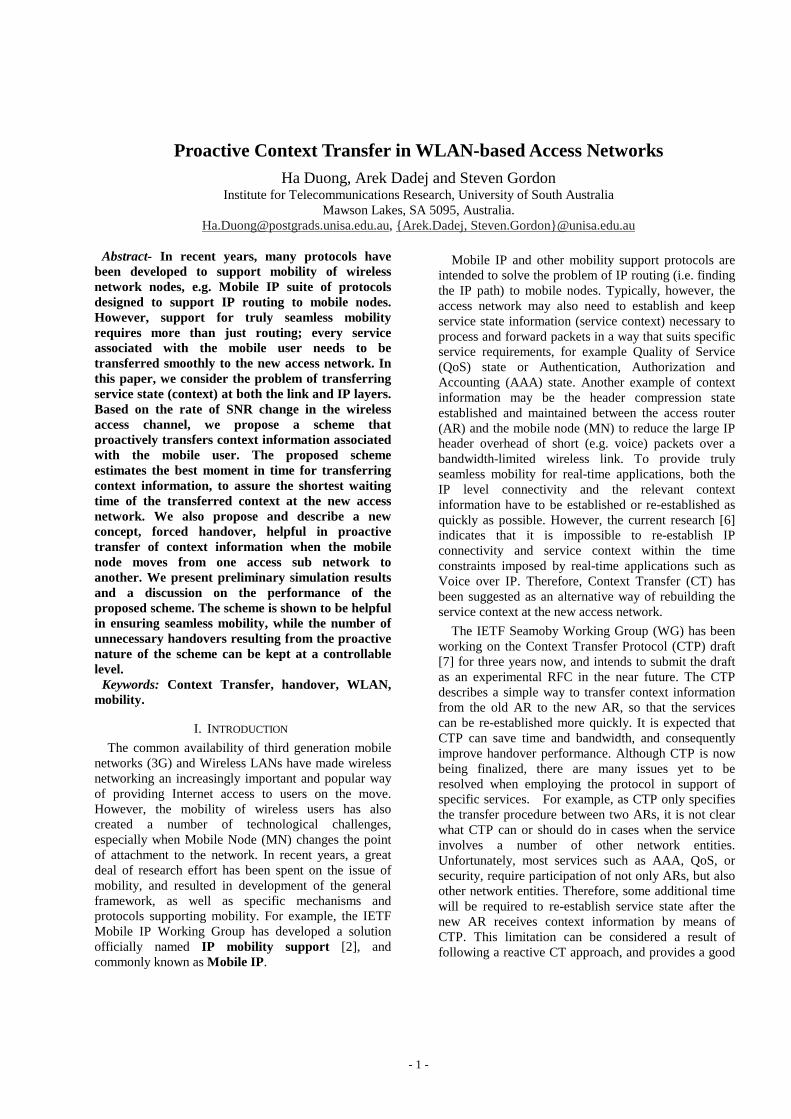
An inter-AP handover may result in an inter-AR handover, depending on whether the old AP and the new AP connect to the same AR or not. As an example, Fig. 1 illustrates a MN roaming in an area served by AR1 and AR2. The MN encounters an inter-AP handover when it moves from the cell served by the AP1 to the cell served by the AP2. However, when the MN switches from AP2 to AP3, it results in an inter-AR handover from AR1 to AR2.
A. 802.11 handover between Access Points based on relative signal strength with hysteresis and threshold.
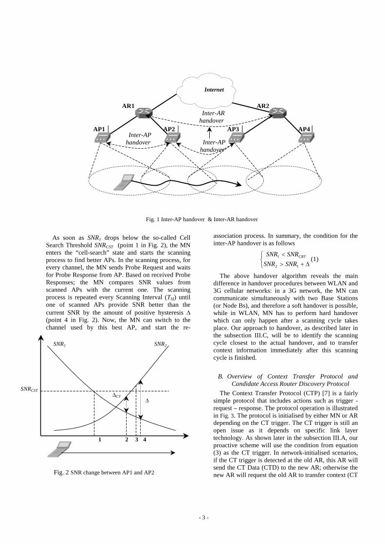
In the 802.11 WLAN, a MN leaving an AP is required to find the next AP and re-associate with this AP. A fundamental question is when does the MN need to switch from one AP to another. Typically, in most of implementations, for example in [8], quality of the communication link is used to make the handover decision, although in some other implementations, e.g. [3], the current load on the APs is also taken into account. In Fig. 2, the typical parameter of communication quality, signal-to-noise ratio (SNR) changes between two adjacent APs, AP1 and AP2. As MN is leaving AP1 toward AP2, the SNR1 from AP1 decreases, and the SNR2 from AP2 increases.
- 3 -
Fig. 1 Inter-AP handover & Inter-AR handover
As soon as SNR1 drops below the so-called Cell Search Threshold SNRCST (point 1 in Fig. 2), the MN enters the “cell-search” state and starts the scanning process to find better APs. In the scanning process, for every channel, the MN sends Probe Request and waits for Probe Response from AP. Based on received Probe Responses; the MN compares SNR values from scanned APs with the current one. The scanning process is repeated every Scanning Interval (TSI) until one of scanned APs provide SNR better than the current SNR by the amount of positive hysteresis ' (point 4 in Fig. 2). Now, the MN can switch to the channel used by this best AP, and start the re-
association process. In summary, the condition for the inter-AP handover is as follows
®̄ '�!�
12
1
SNRSNR
SNRSNR CRT (1)
The above handover algorithm reveals the main difference in handover procedures between WLAN and 3G cellular networks: in a 3G network, the MN can communicate simultaneously with two Base Stations (or Node Bs), and therefore a soft handover is possible, while in WLAN, MN has to perform hard handover which can only happen after a scanning cycle takes place. Our approach to handover, as described later in the subsection III.C, will be to identify the scanning cycle closest to the actual handover, and to transfer context information immediately after this scanning cycle is finished.
B. Overview of Context Transfer Protocol and Candidate Access Router Discovery Protocol
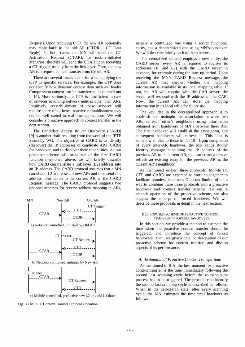
The Context Transfer Protocol (CTP) [7] is a fairly simple protocol that includes actions such as trigger - request – response. The protocol operation is illustrated in Fig. 3. The protocol is initialised by either MN or AR depending on the CT trigger. The CT trigger is still an open issue as it depends on specific link layer technology. As shown later in the subsection III.A, our proactive scheme will use the condition from equation (3) as the CT trigger. In network-initialised scenarios, if the CT trigger is detected at the old AR, this AR will send the CT Data (CTD) to the new AR; otherwise the new AR will request the old AR to transfer context (CT
Fig. 2 SNR change between AP1 and AP2
AP1
AR1
AP2
AR2
AP3 AP4Inter-AP
handover
Inter-AR handover
Inter-AP handover
Internet
SNR1 SNR2
SNRCST 'CT '
1 2 3 4
- 4 -
Request). Upon receiving CTD, the new AR optionally may reply back to the old AR (CTDR – CT Data Reply). In both cases, the MN will send the CT Activation Request (CTAR). In mobile-initiated scenarios, the MN will send the CTAR upon receiving a CT trigger, usually from the link layer. Then, the new AR can request context transfer from the old AR.
There are several issues that arise when applying the CTP to specific services. For example, the CTP does not specify how dynamic context data such as Header Compression context can be transferred, as pointed out in [4]. More seriously, the CTP is insufficient in case of services involving network entities other than ARs. Intuitively, reestablishment of these services will require more time; hence reactive reestablishment may not be well suited to real-time applications. We will consider a proactive approach to context transfer in the next section.
The Candidate Access Router Discovery (CARD) [9] is another draft resulting from the work of the IETF Seamoby WG. The objective of CARD is to identify (discover) the IP addresses of candidate ARs (CARs) for handover, and to discover their capabilities. As our proactive scheme will make use of the first CARD function mentioned above, we will briefly describe how CARD can translate a link layer (L2) address into an IP address. The CARD protocol assumes that a MN can obtain L2 addresses of new APs and then send this address information to the current AR, in the CARD Request message. The CARD protocol suggests two optional schemes for reverse address mapping in ARs,
namely a centralized one using a server functional entity, and a decentralized one using MN’ s handover. We will describe briefly each of them below.
The centralized scheme employs a new entity, the CARD server; every AR is required to register its addresses (IP and L2) with the CARD server in advance, for example during the start up period. Upon receiving the MN’ s CARD Request message, the current AR first checks whether the mapping information is available in its local mapping table. If not, the AR will enquire with the CAR server; the server will respond with the IP address of the CAR. Now, the current AR can store the mapping information in its local table for future use.
The key idea in the decentralized approach is to establish and maintain the association between two ARs as each other’ s neighbours using information obtained from handovers of MN’ s between these Ars. The first handover will establish the association, and subsequent handovers will refresh it. This idea is somehow similar to those in [1][10]. Upon completion of every inter-AR handover, the MN sends Router Identity message containing the IP address of the previous AR to its current AR; this can create a new or refresh an existing entry for the previous AR as the current AR’ s neighbour.
As mentioned earlier, three protocols, Mobile IP, CTP and CARD are expected to work to together to facilitate seamless handover. Our contribution offers a way to combine these three protocols into a proactive handover and context transfer scheme. To ensure smooth operation of the proactive scheme, we also suggest the concept of forced handover. We will describe these proposals in detail in the next section.
III. PROPOSED SCHEME OF PROACTIVE CONTEXT
TRANSFER IN FORCED HANDOVERS
In this section, we provide a method to estimate the time when the proactive context transfer should be triggered, and introduce the concept of forced handovers. Then, we give a detailed description of our proactive scheme for context transfer, and discuss aspects of its performance.
A. Estimation of Proactive Context Transfer time
As mentioned in II.A, the best moment for proactive context transfer is the time immediately following the second last scanning cycle before the re-association process has to be triggered. The procedure to identify the second last scanning cycle is described as follows. When in the cell-search state, after every scanning cycle, the MN estimates the time until handover as follows
Fig. 3 The IETF Context Transfer Protocol Operation
MN New AR Old AR
a) Network controlled, initiated by Old AR
CT Trigger CTD
CTAR CTDR
CT Trigger CT Request
CTD CTAR
CTDR
b) Network controlled, initiated by New AR
CT Trigger CTAR
CT Request
CTD
c) Mobile controlled, predictive new L2 up / old L2 down
- 5 -
� �12
12_
SNRSNRhandoveruntil RR
SNRSNRT �
��' (2)
where RSNR1 and RSNR2 are rates of SNR change for signals from the current AP and the scanned AP respectively. These rate values are obtained and updated on the basis of SNR measurements performed as part of the current and previous scanning cycles.
If the Tuntil_handover is less or equal to the TSI (point 3 in Fig. 2), the current scanning cycle is likely to be the second last (now called scanning-to-CT), and in the next scanning cycle (now called scanning-to-handover), the handover condition is likely to be satisfied. In short, the MN identifies the scanning-to-CT by
SIhandoveruntil TT d_ (3)
To reduce computation, the MN may start to estimate the Tuntil_handover when the following condition is satisfied
®̄ '�!�
CT
CRT
SNRSNR
SNRSNR
12
1 (4)
where 'CT is less than '.
'CT (point 2 in Fig. 2) should be selected such that there is at least one scanning cycle before scanning-to-handover; therefore it can be defined from the following formula
SISNRSNR
CT TRR
�'�'
max1max2
(5)
where RSNR1max and RSNR2max are maximum rates of SNR change from the current AP and the scanned AP. The rate values of interest can be learnt (estimated) from previous measurements, or pre-set.
B. Forced or Active Handover
The above technique can produce a good estimate of the time for proactive CT (scanning-to-CT) and the time for handover (scanning-to-handover). This will be later confirmed by simulation. However, there is not a 100% guarantee that the handover condition (1) will be satisfied at the time of scanning-to-handover. One can argue that if the handover condition (1) is not satisfied at the time of scanning-to-handover, the MN may wait until the next scanning. However, in this case we need to set up a longer waiting time for the transferred context at the new access router, and consequently there may be more resources wasted. We suggest a forced handover, i.e. the MN will make the handover after the scanning-to-handover time is reached, regardless of whether the handover condition (1) is satisfied or not. The main advantage of such forced handover is that the MN knows exactly when the handover will happen, and therefore can set up an
appropriate waiting time for the transferred context at the new access network. The forced handover at the link layer level also allows the MN sufficient time to prepare for the IP level handover. For example, the MN may use the forced handover as a trigger to send an Agent Solicitation message [2] to acquire the Router Advertisement message [2] from a new Foreign Agent (FA); therefore it can reduce the Agent Discovery time (TAD) to as low as one Round Trip Time (RTT) between the MN and the new FA. The TAD can be further reduced if the MN is able to receive the information needed for registration with the new FA through the CARD Reply message (more details will be given in the subsection C). This information enables the MN to create a Registration Request message [2] in advance and send it immediately after the MN re-establishes the link level connection to the new access network. The shortcoming of forced handover is that in some cases, handover is forced to happen when the handover condition (1) is not yet satisfied; therefore, the number of unnecessary handovers may increase. However, this number can be kept at a reasonably low level as shown in the subsection IV.B.
C. Description of the proactive process
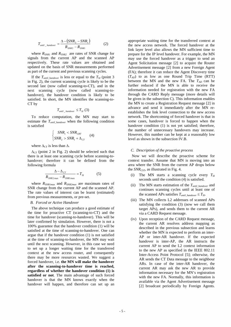
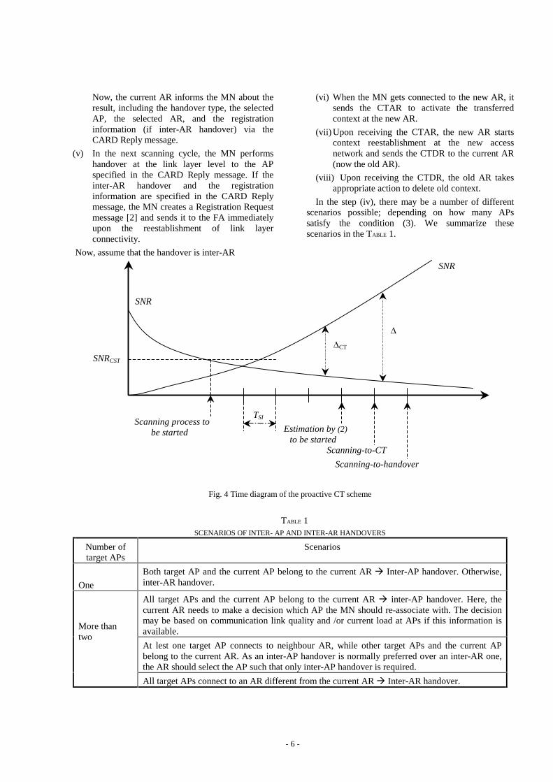
Now we will describe the proactive scheme for context transfer. Assume that MN is moving into an area where the SNR from the current AP drops below the SNRCST, as illustrated in Fig. 4.
(i) The MN starts a scanning cycle every TSI seconds until the condition (4) is satisfied.
(ii) The MN starts estimation of the Tuntil_handover and continues scanning cycles until at least one of the scanned APs satisfies Tuntil_handover d TSI.
(iii) The MN collects L2 addresses of scanned APs satisfying the condition (3) (now we call them target APs), and sends them to the current AR via a CARD Request message.
(iv) Upon reception of the CARD Request message, the current AR resolves address mapping as described in the previous subsection and learns whether the MN is expected to perform an inter-AP or inter-AR handover. If the expected handover is inter-AP, the AR instructs the current AP to send the L2 context information to the new AP as specified in the IEEE 802.11 Inter-Access Point Protocol [5]; otherwise, the AR sends the CT Data message to the neighbour ARs. In case of the inter-AR handover, the current AR may ask the new AR to provide information necessary for the MN’ s registration with the new FA. Normally, this information is available via the Agent Advertisement message [2] broadcast periodically by Foreign Agents.
- 6 -
Now, the current AR informs the MN about the result, including the handover type, the selected AP, the selected AR, and the registration information (if inter-AR handover) via the CARD Reply message.
(v) In the next scanning cycle, the MN performs handover at the link layer level to the AP specified in the CARD Reply message. If the inter-AR handover and the registration information are specified in the CARD Reply message, the MN creates a Registration Request message [2] and sends it to the FA immediately upon the reestablishment of link layer connectivity.
Now, assume that the handover is inter-AR
(vi) When the MN gets connected to the new AR, it sends the CTAR to activate the transferred context at the new AR.
(vii) Upon receiving the CTAR, the new AR starts context reestablishment at the new access network and sends the CTDR to the current AR (now the old AR).
(viii) Upon receiving the CTDR, the old AR takes appropriate action to delete old context.
In the step (iv), there may be a number of different scenarios possible; depending on how many APs satisfy the condition (3). We summarize these scenarios in the TABLE 1.
Fig. 4 Time diagram of the proactive CT scheme
TABLE 1 SCENARIOS OF INTER- AP AND INTER-AR HANDOVERS
Number of target APs
Scenarios
One
Both target AP and the current AP belong to the current AR Æ Inter-AP handover. Otherwise, inter-AR handover.
All target APs and the current AP belong to the current AR Æ inter-AP handover. Here, the current AR needs to make a decision which AP the MN should re-associate with. The decision may be based on communication link quality and /or current load at APs if this information is available.
At lest one target AP connects to neighbour AR, while other target APs and the current AP belong to the current AR. As an inter-AP handover is normally preferred over an inter-AR one, the AR should select the AP such that only inter-AP handover is required.
More than two
All target APs connect to an AR different from the current AR Æ Inter-AR handover.
Scanning process to be started
SNR
SNR
SNRCST
'CT
'
TSI
Estimation by (2) to be started
Scanning-to-CT Scanning-to-handover

- 7 -
D. Performance metrics
While the advantages of forced handovers are very clear, in this paper we also investigate the disadvantages of the proposed scheme, and attempt to assess their significance. To evaluate the proposed proactive scheme, we define a perfect handover as follows:
(a) At the time of the scanning-to-CT, i.e. Tuntil_handover is less or equal TSI, the condition (1) is not yet satisfied
(b) The handover condition (1) is satisfied at the time of the next scanning, the scanning-to-handover.
(c) There is sufficient time for the proactive scheme to be completed.
Fig. 5 shows an example of perfect handover. We define the proactive scheme completion as a state in which the MN is able to send the CARD Request message and receive the CARD Reply message. We denote the completion time as Tcompletion. The violation of any of the three conditions used in the above definition of perfect handover means that the handover is imperfect.
The imperfect handover of type I (Fig. 6) can be considered a “premature” handover that could become an unnecessary handover. Therefore, the probability of this type of imperfect handover (Pim_HO_typeI) determines the upper bound on the probability of unnecessary handover (Pun_HO). The unnecessary handover happens
Fig. 5 Time diagram of perfect handover
Fig. 6 Time diagram of type I imperfect handover
Fig. 7 Time diagram of type II imperfect handover.
Fig. 8 Time diagram of type III imperfect handover when the
completion time is greater than the scanning time TSI. (The type III imperfect handover also occurs if the MN loses the current connectivity before receiving the CARD Reply message.)
SNR1
SNR2
'CT '
Scanning-to-CT Scanning-to-handover
SNR1
SNR2
'CT '
Scanning-to-CT Scanning-to-handover
Tcompletion
SNR1
SNR2
'CT '
Scanning-to-CT Scanning-to-handover
SNR1
SNR2
'CT '
Scanning-to-CT Scanning-to-handover
Tcompletion
- 8 -
when the MN moves in such a way that the handover condition (1) is never satisfied. For example, the MN changes the direction of movement or stops after the scanning-to-CT time. The unnecessary handover wastes network resources; therefore its probability should be as small as possible
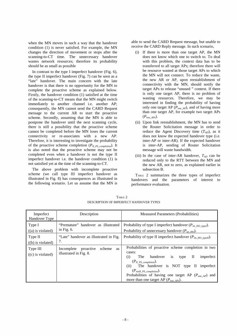
In contrast to the type I imperfect handover (Fig. 6), the type II imperfect handover (Fig. 7) can be seen as a “late” handover. The main concern with the late handover is that there is no opportunity for the MN to complete the proactive scheme as explained below. Firstly, the handover condition (1) satisfied at the time of the scanning-to-CT means that the MN might switch immediately to another channel i.e. another AP; consequently, the MN cannot send the CARD Request message to the current AR to start the proactive scheme. Secondly, assuming that the MN is able to postpone the handover until the next scanning cycle, there is still a possibility that the proactive scheme cannot be completed before the MN loses the current connectivity or re-associates with a new AP. Therefore, it is interesting to investigate the probability of the proactive scheme completion (PII_PS_completion). It is also noted that the proactive scheme may not be completed even when a handover is not the type II imperfect handover i.e. the handover condition (1) is not satisfied yet at the time of the scanning-to-CT.
The above problem with incomplete proactive scheme (we call type III imperfect handover as illustrated in Fig. 8) has consequences as illustrated in the following scenario. Let us assume that the MN is
able to send the CARD Request message, but unable to receive the CARD Reply message. In such scenario,
(i) If there is more than one target AP, the MN does not know which one to switch to. To deal with this problem, the context data has to be transferred to all target APs; therefore there will be resource wasted at those target APs to which the MN will not connect. To reduce the waste, the new AR or AP, upon reestablishment of connectivity with the MN, should notify the target APs to release “unused ” context. If there is only one target AP, there is no problem of wasting resources. Therefore, we may be interested in finding the probability of having only one target AP (Pone_AP), and of having more than one target AP, for example two target APs (Ptwo_APs).
(ii) Upon link reestablishment, the MN has to send the Router Solicitation message in order to reduce the Agent Discovery time (TAD), as it does not know the expected handover type (i.e. inter-AP or inter-AR). If the expected handover is inter-AP, sending of Router Solicitation message will waste bandwidth.
(iii) In the case of inter-AR handover, TAD can be reduced only to the RTT between the MN and the new AR, not to zero, as explained earlier in subsection B.
TABLE 2 summarizes the three types of imperfect handovers and the parameters of interest to performance evaluation.
TABLE 2 DESCRIPTION OF IMPERFECT HANDOVER TYPES
Imperfect Handover Type
Description Measured Parameters (Probabilities)
Type I
((a) is violated)
“Premature” handover as illustrated in Fig. 6.
Probability of type I imperfect handover (Pim_HO_typeI).
Probability of unnecessary handover (Pun_HO).
Type II
((b) is violated)
“Late” handover as illustrated in Fig. 7.
Probability of type II imperfect handover (Pim_HO_typeII).
Type III
((c) is violated)
Incomplete proactive scheme as illustrated in Fig. 8.
Probabilities of proactive scheme completion in two cases: (i) The handover is type II imperfect
(PII_PS_completion). (ii) The handover is NOT type II imperfect
(PnotII_PS_completion). Probabilities of having one target AP (Pone_AP) and more than one target AP (Ptwo_APs).
- 9 -
Of the three types of imperfect handovers, the type I and type III imperfect handovers are more important than type II. The type I imperfect handover is directly related to unnecessary handover, and the type III reduces benefits from the proposed proactive scheme. The type II imperfect is less significant, because it only affects the probability of incomplete proactive scheme as explained in the next section.
IV. S IMULATION RESULTS
In this section, we describe the simulation scenario; present simulation results and follow up with a discussion.
A. Simulation scenario and objectives.
The simulation area is covered by 61 APs distributed uniformly at a distance of 200m from each other. Transmission power of all APs is the same, and there are no obstructions to transmissions as the simulation area is assumed an open outdoor environment. Every AP, excluding the APs residing close to the edges, has 6 neighbour APs. In the simulation area, the MN is moving according to the random waypoint model as follows. After randomly selecting a destination, the MN moves towards the selected destination with a constant velocity v (the velocity v is randomly selected from a range of (0.5 m/s – 5 m/s)). After reaching the destination, the MN stops for the duration of pause time and then selects another destination and speed and moves again.
Based on the discussion of performance metrics in the previous section, the simulation objective is to investigate
(iii) How significant is the probability of unnecessary handover Pun_HO?
(iv) If type II imperfect handover occurs, what is the probability of proactive scheme completion (PII_PS_completion)? This probability is also investigated for cases when the type II imperfect handover DOES NOT occur (PnotII_PS_completion), to complete the picture of proactive scheme completion
(v) What are the probabilities of having one target APs (Pone_AP) and two target APs (Ptwo_APs)?
The above parameters are investigated in the context of different scanning intervals TSI and hystereses '. As we will see in the next subsection, smaller TSI usually give a better performance. It is expected, since with smaller TSI, the estimation of (2) is performed more frequently, hence produces more accurate predictions. On the other hand, smaller TSI means that the MN has to interrupt the current communications more frequently in order to perform scanning.
B. Numerical results and discussion
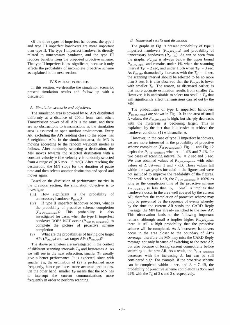
The graphs in Fig. 9 present probability of type I imperfect handovers (Pim_HO_typeI) and probability of unnecessary handovers (Pun_HO). As can be seen from the graphs, Pun_HO is always below the upper bound Pim_HO_typeI, and remains under 1% when the scanning interval TSI = 2 sec, and under 1.5% when TSI = 3 sec. As Pun_HO dramatically increases with the TSI = 4 sec, the scanning interval should be selected to be no more than 3 sec. It is also observed that the Pun_HO is lower with smaller TSI. The reason, as discussed earlier, is that more accurate estimation results from smaller TSI. However, it is undesirable to select too small a TSI that will significantly affect transmissions carried out by the MN.
The probabilities of type II imperfect handovers (Pim_HO_typeII) are shown in Fig. 10. In the area of small ' values, the Pim_HO_typeII is high, but sharply decreases with the hysteresis ' becoming larger. This is explained by the fact that it is easier to achieve the handover condition (1) with smaller '.
However, in the case of type II imperfect handovers, we are more interested in the probability of proactive scheme completion (PII_PS_completion). Fig. 11 and Fig. 12 depict the PII_PS_completion when ' = 1 dB and 7 dB, for two cases of scanning interval TSI = 2 sec and 3 sec. We also obtained values of PII_PS_completion with other values of ' between 1 and 7 dB. Those values fall within the two graphs included in the figures and were not included to improve the readability of the figures. For small ' such as 1 dB, the PII_PS_completion is 100% as long as the completion time of the proactive scheme TPS_completion is less than TSI. Small ' implies that handovers occur in the area well covered by the current AP; therefore the completion of proactive scheme may only be prevented by the sequence of events whereby by the time the current AR sends the CARD Reply message, the MN has already switched to the new AP. This observation leads to the following important remark: although small ' implies higher Pim_HO_typeII, there is still a high probability that the proactive scheme will be completed. As ' increases, handovers occur in the area closer to the boundary of AP’ s coverage; therefore the MN may miss the CARD Reply message not only because of switching to the new AP, but also because of losing current connectivity before switching to the new AR. As a result, the PII_PS_completion decreases with the increasing ', but can be still considered high. For example, if the proactive scheme can be completed within 1 sec, and ' = 7 dB, the probability of proactive scheme completion is 95% and 92% with the TSI of 2 s and 3 s respectively.
- 10 -
Fig. 9 Probability of the type I imperfect handover (Pim_HO_typeI) and probability of the unnecessary handover (Pun_HO).
Fig. 10 Probability of the type II imperfect handover (Pim_HO_typeII).
Fig. 11 Probability of proactive scheme completion (PII_PS_completion) in the case of the type II imperfect handover (scanning time TSI = 2 sec).
Fig. 12 Probability of proactive scheme completion (PII_PS_completion) in the case of type II imperfect handovers (scanning time TSI = 3 sec).
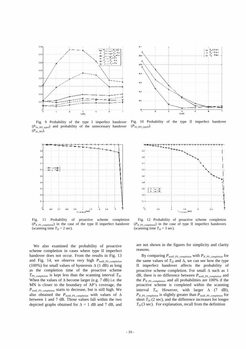
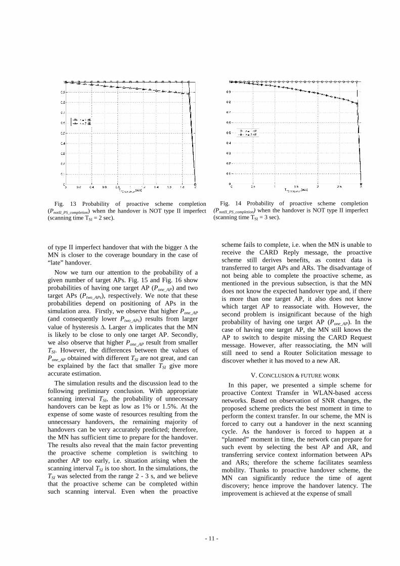
We also examined the probability of proactive scheme completion in cases where type II imperfect handover does not occur. From the results in Fig. 13 and Fig. 14, we observe very high PnotII_PS_completion (100%) for small values of hysteresis ' (1 dB) as long as the completion time of the proactive scheme TPS_completion is kept less than the scanning interval TSI. When the values of ' become larger (e.g. 7 dB) i.e. the MN is closer to the boundary of AP’ s coverage, the PnotII_PS_completion starts to decrease, but is still high. We also obtained the PnotII_PS_completion with values of ' between 1 and 7 dB. Those values fall within the two depicted graphs obtained for ' = 1 dB and 7 dB, and
are not shown in the figures for simplicity and clarity reasons.
By comparing PnotII_PS_completion with PII_PS_completion for the same values of TSI and ', we can see how the type II imperfect handover affects the probability of proactive scheme completion. For small ' such as 1 dB, there is no difference between PnotII_PS_completion and the PII_PS_completion, and all probabilities are 100% if the proactive scheme is completed within the scanning interval TSI. However, with larger ' (7 dB), PII_PS_completion is slightly greater than PnotII_PS_completion for short TSI (2 sec), and the difference increases for longer TSI (3 sec). For explanation, recall from the definition
- 11 -
of type II imperfect handover that with the bigger ' the MN is closer to the coverage boundary in the case of “ late” handover.
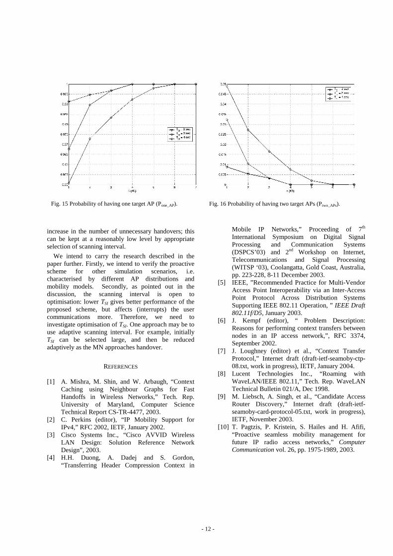
Now we turn our attention to the probability of a given number of target APs. Fig. 15 and Fig. 16 show probabilities of having one target AP (Pone_AP) and two target APs (Ptwo_APs), respectively. We note that these probabilities depend on positioning of APs in the simulation area. Firstly, we observe that higher Pone_AP (and consequently lower Ptwo_APs) results from larger value of hysteresis '. Larger ' implicates that the MN is likely to be close to only one target AP. Secondly, we also observe that higher Pone_AP result from smaller TSI. However, the differences between the values of Pone_AP obtained with different TSI are not great, and can be explained by the fact that smaller TSI give more accurate estimation.
The simulation results and the discussion lead to the following preliminary conclusion. With appropriate scanning interval TSI, the probability of unnecessary handovers can be kept as low as 1% or 1.5%. At the expense of some waste of resources resulting from the unnecessary handovers, the remaining majority of handovers can be very accurately predicted; therefore, the MN has sufficient time to prepare for the handover. The results also reveal that the main factor preventing the proactive scheme completion is switching to another AP too early, i.e. situation arising when the scanning interval TSI is too short. In the simulations, the TSI was selected from the range 2 - 3 s, and we believe that the proactive scheme can be completed within such scanning interval. Even when the proactive
scheme fails to complete, i.e. when the MN is unable to receive the CARD Reply message, the proactive scheme still derives benefits, as context data is transferred to target APs and ARs. The disadvantage of not being able to complete the proactive scheme, as mentioned in the previous subsection, is that the MN does not know the expected handover type and, if there is more than one target AP, it also does not know which target AP to reassociate with. However, the second problem is insignificant because of the high probability of having one target AP (Pone_AP). In the case of having one target AP, the MN still knows the AP to switch to despite missing the CARD Request message. However, after reassociating, the MN will still need to send a Router Solicitation message to discover whether it has moved to a new AR.
V. CONCLUSION & FUTURE WORK
In this paper, we presented a simple scheme for proactive Context Transfer in WLAN-based access networks. Based on observation of SNR changes, the proposed scheme predicts the best moment in time to perform the context transfer. In our scheme, the MN is forced to carry out a handover in the next scanning cycle. As the handover is forced to happen at a “ planned” moment in time, the network can prepare for such event by selecting the best AP and AR, and transferring service context information between APs and ARs; therefore the scheme facilitates seamless mobility. Thanks to proactive handover scheme, the MN can significantly reduce the time of agent discovery; hence improve the handover latency. The improvement is achieved at the expense of small
Fig. 13 Probability of proactive scheme completion (PnotII_PS_completion) when the handover is NOT type II imperfect (scanning time TSI = 2 sec).
Fig. 14 Probability of proactive scheme completion (PnotII_PS_completion) when the handover is NOT type II imperfect (scanning time TSI = 3 sec).
- 12 -
Fig. 15 Probability of having one target AP (Pone_AP).
Fig. 16 Probability of having two target APs (Ptwo_APs).
increase in the number of unnecessary handovers; this can be kept at a reasonably low level by appropriate selection of scanning interval.
We intend to carry the research described in the paper further. Firstly, we intend to verify the proactive scheme for other simulation scenarios, i.e. characterised by different AP distributions and mobility models. Secondly, as pointed out in the discussion, the scanning interval is open to optimisation: lower TSI gives better performance of the proposed scheme, but affects (interrupts) the user communications more. Therefore, we need to investigate optimisation of TSI. One approach may be to use adaptive scanning interval. For example, initially TSI can be selected large, and then be reduced adaptively as the MN approaches handover.
REFERENCES [1] A. Mishra, M. Shin, and W. Arbaugh, “ Context
Caching using Neighbour Graphs for Fast Handoffs in Wireless Networks,” Tech. Rep. University of Maryland, Computer Science Technical Report CS-TR-4477, 2003.
[2] C. Perkins (editor), “ IP Mobility Support for IPv4,” RFC 2002, IETF, January 2002.
[3] Cisco Systems Inc., “ Cisco AVVID Wireless LAN Design: Solution Reference Network Design” , 2003.
[4] H.H. Duong, A. Dadej and S. Gordon, “ Transferring Header Compression Context in
Mobile IP Networks,” Proceeding of 7th International Symposium on Digital Signal Processing and Communication Systems (DSPCS’ 03) and 2nd Workshop on Internet, Telecommunications and Signal Processing (WITSP ‘03), Coolangatta, Gold Coast, Australia, pp. 223-228, 8-11 December 2003.
[5] IEEE, ” Recommended Practice for Multi-Vendor Access Point Interoperability via an Inter-Access Point Protocol Across Distribution Systems Supporting IEEE 802.11 Operation, ” IEEE Draft 802.11f/D5, January 2003.
[6] J. Kempf (editor), “ Problem Description: Reasons for performing context transfers between nodes in an IP access network,” , RFC 3374, September 2002.
[7] J. Loughney (editor) et al., “ Context Transfer Protocol,” Internet draft (draft-ietf-seamoby-ctp-08.txt, work in progress), IETF, January 2004.
[8] Lucent Technologies Inc., “ Roaming with WaveLAN/IEEE 802.11,” Tech. Rep. WaveLAN Technical Bulletin 021/A, Dec 1998.
[9] M. Liebsch, A. Singh, et al., “ Candidate Access Router Discovery,” Internet draft (draft-ietf-seamoby-card-protocol-05.txt, work in progress), IETF, November 2003.
[10] T. Pagtzis, P. Kristein, S. Hailes and H. Afifi, “ Proactive seamless mobility management for future IP radio access networks,” Computer Communication vol. 26, pp. 1975-1989, 2003.