probing systems for cnc machine tools
TRANSCRIPT
H-2000-3020-08-C Technical specifications
Probing systems for CNC machine tools
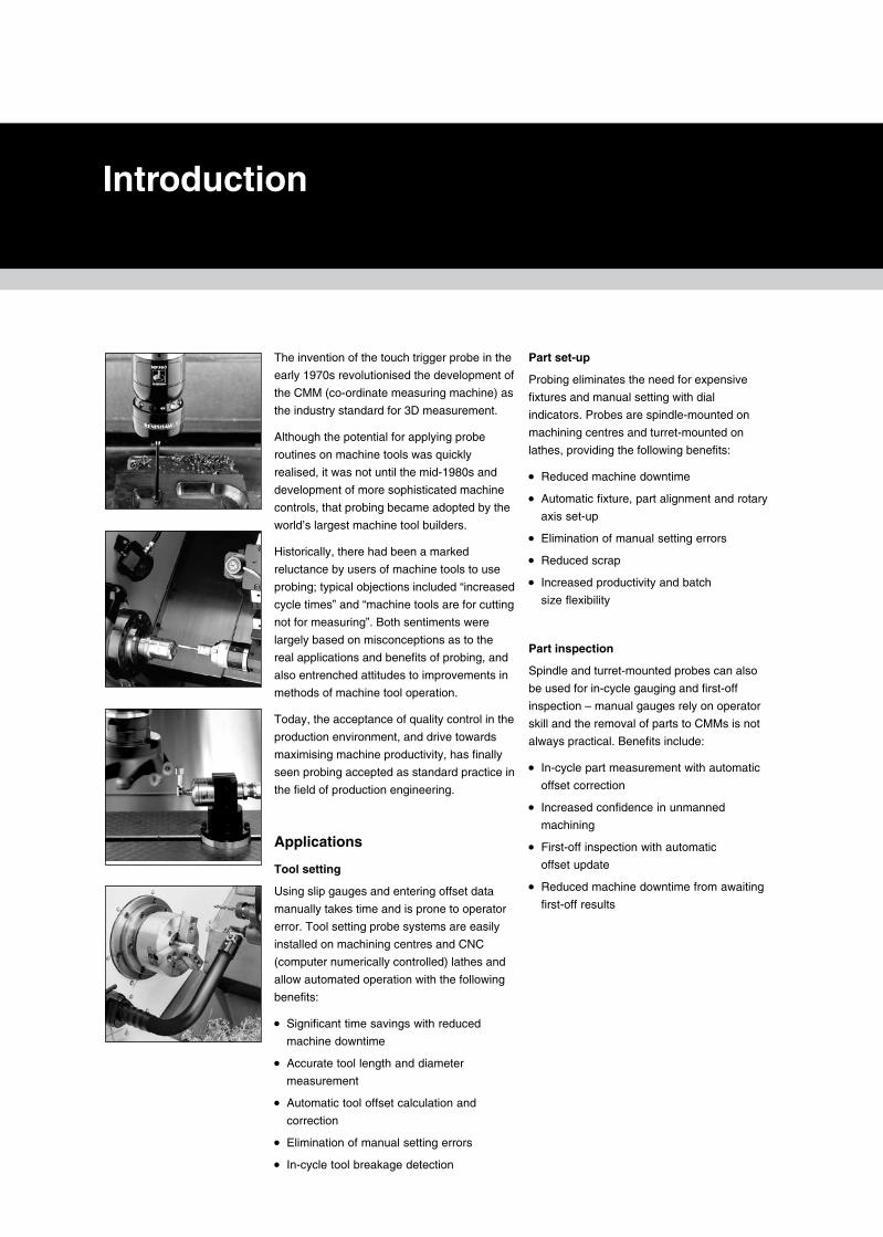
The invention of the touch trigger probe in the
early 1970s revolutionised the development of
the CMM (co-ordinate measuring machine) as
the industry standard for 3D measurement.
Although the potential for applying probe
routines on machine tools was quickly
realised, it was not until the mid-1980s and
development of more sophisticated machine
controls, that probing became adopted by the
world’s largest machine tool builders.
Historically, there had been a marked
reluctance by users of machine tools to use
probing; typical objections included “increased
cycle times” and “machine tools are for cutting
not for measuring”. Both sentiments were
largely based on misconceptions as to the
real applications and benefits of probing, and
also entrenched attitudes to improvements in
methods of machine tool operation.
Today, the acceptance of quality control in the
production environment, and drive towards
maximising machine productivity, has finally
seen probing accepted as standard practice in
the field of production engineering.
Applications
Tool setting
Using slip gauges and entering offset data
manually takes time and is prone to operator
error. Tool setting probe systems are easily
installed on machining centres and CNC
(computer numerically controlled) lathes and
allow automated operation with the following
benefits:
• Significant time savings with reduced
machine downtime
• Accurate tool length and diameter
measurement
• Automatic tool offset calculation and
correction
• Elimination of manual setting errors
• In-cycle tool breakage detection
Introduction
Part set-up
Probing eliminates the need for expensive
fixtures and manual setting with dial
indicators. Probes are spindle-mounted on
machining centres and turret-mounted on
lathes, providing the following benefits:
• Reduced machine downtime
• Automatic fixture, part alignment and rotary
axis set-up
• Elimination of manual setting errors
• Reduced scrap
• Increased productivity and batch
size flexibility
Part inspection
Spindle and turret-mounted probes can also
be used for in-cycle gauging and first-off
inspection – manual gauges rely on operator
skill and the removal of parts to CMMs is not
always practical. Benefits include:
• In-cycle part measurement with automatic
offset correction
• Increased confidence in unmanned
machining
• First-off inspection with automatic
offset update
• Reduced machine downtime from awaiting
first-off results

Contents
1.0 Howtousethisguide
2.0 Transmissionselection
3.0 CNCmachiningcentreandmillingmachineinspectionprobingsystems
�4.0 CNCmachiningcentretoolsettingandbreakagedetectionprobingsystems
5.0 CNClatheandgrinderinspectionprobingsystems
�6.0 CNClathetoolsettingprobingsystems
7.0 Machineinterfaceunits
8.0 Shanksandshankadaptors
9.0 Styliandaccessories
10.0 Software
11.0 Customdesignservice
Probing�systems�for�CNC�machine�tools

Probing�systems�for��CNC�machine�tools
This�document�has�been�designed�to�help�
you�to�select�the�ideal�probing�system�for�
your�machine�tool�application.
Renishaw’sbroadproductrangecovers
inspectionandtoolsettingapplicationson
CNCmachiningcentres,lathesandgrinders,
andmanualmillingmachines.
Comprehensiveprobingsoftware,styliand
accessoriescaterforeveryprobingneed.
Whereastandardproductmaynotsuityour
exactrequirements,Renishaw’scustom
designserviceisavailabletotailorasolution.
Probe�system�selection
Thetypeofprobingsystemthatyouneedwill
dependonyourmachinetoolandthenature
oftheprobingapplication.
Thisdocumentcontainssectionsthatfocuson
themainapplicationsforprobingonmachine
tools(seesections3,4,5and6).Atthestart
ofeachsectionisanintroductiontotheuseof
probingforthatapplication,plusguidanceon
selectionofthemostappropriatesystem.The
remainderofthesectioncontainstechnical
informationabouteachprobe.
Forinspectionprobingsystems,youalsoneed
toconsiderthetypeoftransmissionsystem
thatyourequire.Onceagain,thisdecisionwill
dependonthesizeandconfigurationofyour
machinetool.
Selection�procedure
Step�1
Which�probing�application�do�you�require?
1.Inspection/partset-up
GotoStep2.
2.Toolsetting/brokentooldetection
GotoStep3.
Step�2
What�type�of�transmission�do�you�require�
for�your�inspection�probing�system?
Gotosection2(Transmissionselection),
toidentifythebesttransmissionsystemfor
yourmachinetool.Anoverviewwillhelpyou
tochoose,withadetailedspecificationof
transmissionperformanceonthesubsequent
datapages.
Step�3�
Which�probe�is�best�for�your�application?
Gototheappropriatesection(3,4,5or6)
foryourapplication.Onthefirstpageisan
overviewofRenishaw’sproductsandaguide
forprobeselection.Ifnostandardproduct
meetsyourrequirement,refertosection11
(Customdesignservice).
Step�4�
Check�the�probe�details.
Checkthetechnicalinformationlisted
onthedatapagefortheprobethatyou
haveselectedtoensurethatitmeetsyour
requirements.Ifyoursisaninspectionprobing
application,checkthattheprobecanoperate
withthetransmissionsystemthatyouhave
chosen.
Step�5�
Check�the�interface�details.
Theprobedatapagedefinesthecompatible
electricalinterfaceunitforyourchosenprobe.
Gotosection7(Machineinterfaceunits)to
checkthattheinterfaceissuitableforyour
machinetoolcontroller.
Step�6�
Identify�your�shank�adaptor�requirements.
Section8(Shankadaptors)willhelpyou
eithertomakeyourownshankadaptor,
ortochoosefromRenishaw’srangeof
standarditems.
Other�accessories
Styli
Renishawprobesaresuppliedwithstyli
suitableformostapplications.Section9(Styli
andaccessories)givesfurtherinformationon
Renishaw’sstylusrange.Forfulldetails,refer
toRenishaw’stechnicalspecificationStyli and
accessories (partno.H-1000-3200).
Software
Renishawhasacomprehensiverangeof
probingsoftwarepackagessuitablefor
mostprobingapplications.Checksection10
(Software)toseewhethersuitable
probingsoftwareisavailableforyourmachine
toolcontroller.
FormoredetailsofRenishaw’s
probingsoftware,refertothedatasheets
Probe software for machine tools – program
features(partno.H-2000-2289)andProbe
software for machine tools – program
selection list(partno.H-2000-2298).
Ho
w�t
o�u
se�t
his
�gu
ide
1.1
How�to�use�this�guide
CNC�MACHINE�CONTROL
OMP40
OMI
OMP60
OMM
CNC�MACHINE�CONTROL
MI12
OMP60
OMM
ARenishawprobemustbeableto
communicatewiththecontrolsystem
(CNC)ofthemachineonwhichitisfitted.
Signalsmustpassfromtheprobetothe
machine’scontrollertoregistercontactof
theprobe’sstyluswiththecomponentor
tool.Similarly,signalsmustpassfromthe
machine’scontrollertotheprobetocontrol
thefunctioningoftheprobe.
Thepassageofthesesignalsishandled
byatransmission�system.Thechoiceof
transmissionsystemdependsonthetypeof
probeandthetypeofmachinetooltowhich
itisfitted.
Inspectionprobesformachiningcentres
aretypicallylocatedinatoolcarouseland
areinterchangedlikeconventionaltools.
Onlathes,theprobeistypicallyasemi-
permanentfeatureofarotatingturret.
Inbothcase,signallingbetweenprobe
andCNCgenerallyhastoberemote.
Fortool�settingapplications,typicallythe
probeismountedinafixedlocation,thereby
allowingdirectcommunicationbetweenprobe
andCNC.
Renishawprobesusefourmaintypesof
transmissionsystems:
·� Optical
·� Radio
·� Inductive
·� Director‘hard-wired’
Thefollowingsectionsshowtypicalexamples
ofeachofthesesystems:
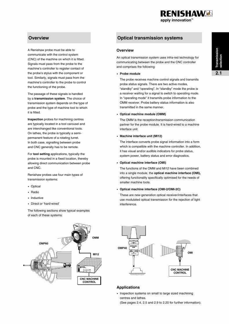
Overview
Anopticaltransmissionsystemusesinfra-redtechnologyfor
communicatingbetweentheprobeandtheCNCcontroller
andcomprisesthefollowing:
·� Probe�module
Theprobereceivesmachinecontrolsignalsandtransmits
probestatussignals.Therearetwoactivemodes,
“standby”and“operating”.In“standby”modetheprobeis
areceiverwaitingforasignaltoswitchtooperatingmode.
In“operatingmode”ittransmitsprobeinformationtothe
OMMreceiver.Probebatterystatusinformationisalso
transmittedinthesamemanner.
·� Optical�machine�module�(OMM)
TheOMMisthereception/transmissioncommunication
partnerfortheprobemodule.Itishard-wiredtoamachine
interfaceunit.
·� Machine�interface�unit�(MI12)
Theinterfaceconvertsprobesignalinformationintoaform
whichiscompatiblewiththemachinecontroller.Inaddition,
ithasvisualand/oraudibleindicatorsforprobestatus,
systempower,batterystatusanderrordiagnostics.
·� Optical�machine�interface�(OMI)
ThefunctionsoftheOMMandMI12havebeencombined
intoasinglemodule,theoptical�machine�interface�(OMI),
offeringfunctionalityspecificallyoptimisedfortheneedsof
smallermachinetools.
·� Optical�machine�interface�(OMI-2/OMI-2C)
Thesearenew-generationopticalreceiver/interfacesthat
usemodulatedopticaltransmissionfortherejectionoflight
interference.
Applications
·� Inspectionsystemsonsmalltolargesizedmachining
centresandlathes.
(Seepages2.4,2.5and2.9to2.20forfurtherinformation).
Tran
smis
sio
n��
sele
ctio
n
2.1
Optical�transmission�systemsOverview
RMI RMP60
CNC�MACHINE�CONTROL
CNC��MACHINE�CONTROL
IMM
MI5
IMP
PROBE
Probing�systems�for��CNC�machine�tools
Tran
smis
sio
n��
sele
ctio
n
2.2
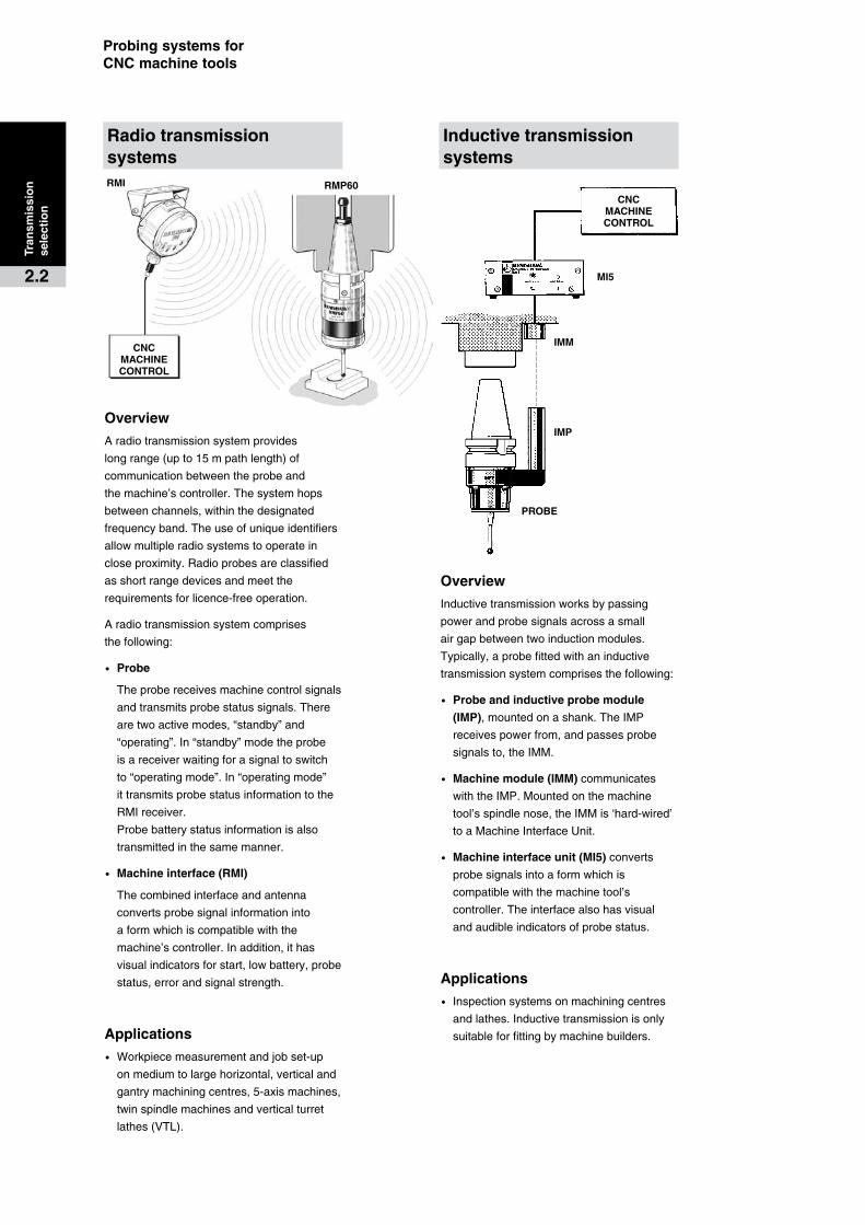
Overview
Aradiotransmissionsystemprovides
longrange(upto15mpathlength)of
communicationbetweentheprobeand
themachine’scontroller.Thesystemhops
betweenchannels,withinthedesignated
frequencyband.Theuseofuniqueidentifiers
allowmultipleradiosystemstooperatein
closeproximity.Radioprobesareclassified
asshortrangedevicesandmeetthe
requirementsforlicence-freeoperation.
Aradiotransmissionsystemcomprises
thefollowing:
·� Probe
Theprobereceivesmachinecontrolsignals
andtransmitsprobestatussignals.There
aretwoactivemodes,“standby”and
“operating”.In“standby”modetheprobe
isareceiverwaitingforasignaltoswitch
to“operatingmode”.In“operatingmode”
ittransmitsprobestatusinformationtothe
RMIreceiver.
Probebatterystatusinformationisalso
transmittedinthesamemanner.
·� Machine�interface�(RMI)
Thecombinedinterfaceandantenna
convertsprobesignalinformationinto
aformwhichiscompatiblewiththe
machine’scontroller.Inaddition,ithas
visualindicatorsforstart,lowbattery,probe
status,errorandsignalstrength.
Applications
·� Workpiecemeasurementandjobset-up
onmediumtolargehorizontal,verticaland
gantrymachiningcentres,5-axismachines,
twinspindlemachinesandverticalturret
lathes(VTL).
Overview
Inductivetransmissionworksbypassing
powerandprobesignalsacrossasmall
airgapbetweentwoinductionmodules.
Typically,aprobefittedwithaninductive
transmissionsystemcomprisesthefollowing:
·� Probe�and�inductive�probe�module�
(IMP),mountedonashank.TheIMP
receivespowerfrom,andpassesprobe
signalsto,theIMM.
·� Machine�module�(IMM)communicates
withtheIMP.Mountedonthemachine
tool’sspindlenose,theIMMis‘hard-wired’
toaMachineInterfaceUnit.
·� Machine�interface�unit�(MI5)converts
probesignalsintoaformwhichis
compatiblewiththemachinetool’s
controller.Theinterfacealsohasvisual
andaudibleindicatorsofprobestatus.
Applications
·� Inspectionsystemsonmachiningcentres
andlathes.Inductivetransmissionisonly
suitableforfittingbymachinebuilders.
Radio�transmission�systems
Inductive�transmission��systems
CNC��MACHINE�CONTROL
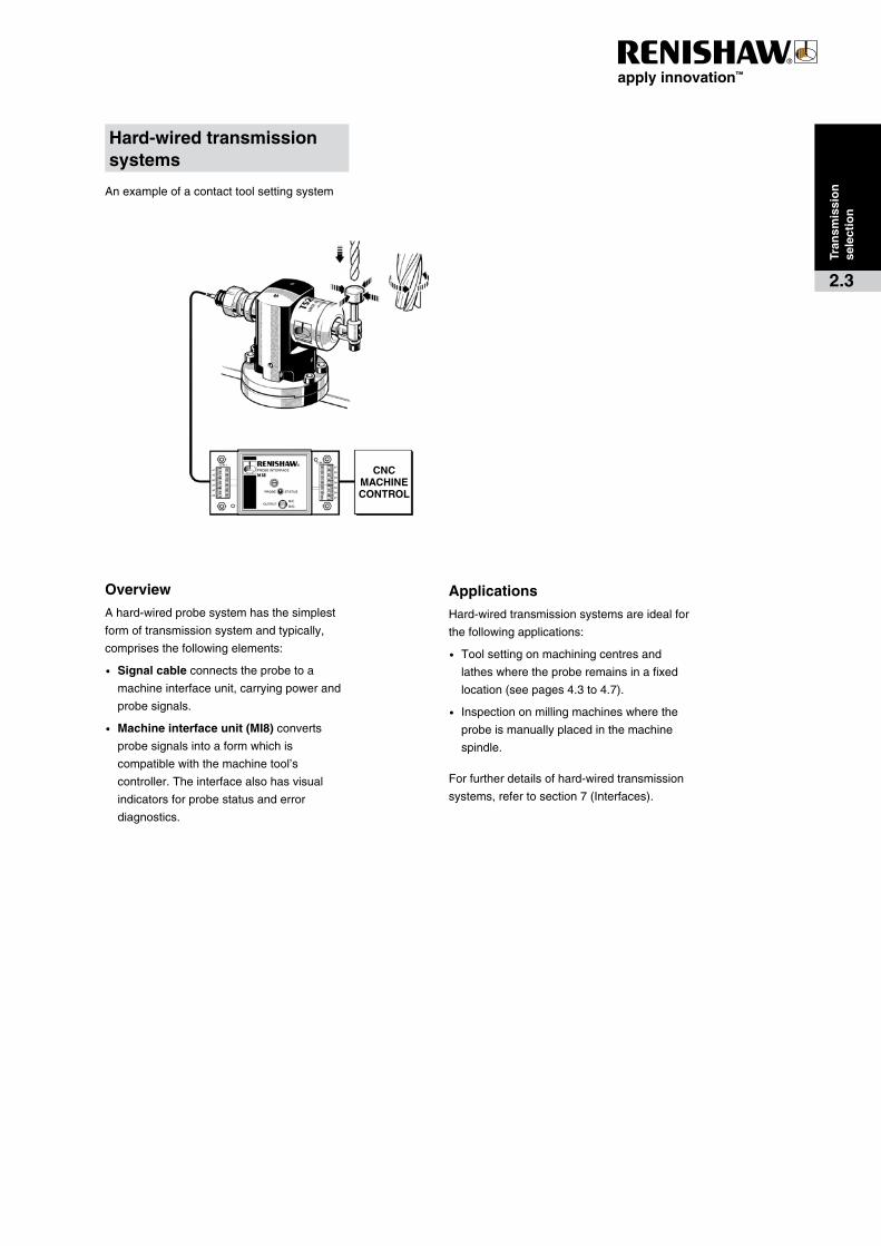
Anexampleofacontacttoolsettingsystem
Tran
smis
sio
n��
sele
ctio
n
2.3
Overview
Ahard-wiredprobesystemhasthesimplest
formoftransmissionsystemandtypically,
comprisesthefollowingelements:
·� Signal�cableconnectstheprobetoa
machineinterfaceunit,carryingpowerand
probesignals.
·� Machine�interface�unit�(MI8)converts
probesignalsintoaformwhichis
compatiblewiththemachinetool’s
controller.Theinterfacealsohasvisual
indicatorsforprobestatusanderror
diagnostics.
Applications
Hard-wiredtransmissionsystemsareidealfor
thefollowingapplications:
·� Toolsettingonmachiningcentresand
latheswheretheproberemainsinafixed
location(seepages4.3to4.7).
·� Inspectiononmillingmachineswherethe
probeismanuallyplacedinthemachine
spindle.
Forfurtherdetailsofhard-wiredtransmission
systems,refertosection7(Interfaces).
Hard-wired�transmission��systems
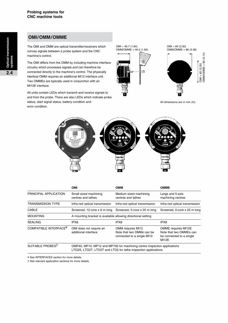
OMI=46.7(1.84)OMM/OMME=46.5(1.83)
OMI=84(3.30)OMM/OMME=86(3.38)
OM
I=
85
(3.3
5)
OM
M/O
MM
E=
80
(3.1
4)
Probing�systems�for��CNC�machine�tools
TheOMIandOMMareopticaltransmitter/receiverswhich
conveysignalsbetweenaprobesystemandtheCNC
machine’scontrol.
TheOMIdiffersfromtheOMMbyincludingmachineinterface
circuitrywhichprocessessignalsandcanthereforebe
connecteddirectlytothemachine’scontrol.Thephysically
identicalOMMrequiresanadditionalMI12interfaceunit.
TwoOMMEsaretypicallyusedinconjunctionwithan
MI12Einterface.
AllunitscontainLEDswhichtransmitandreceivesignalsto
andfromtheprobe.TherearealsoLEDswhichindicateprobe
status,startsignalstatus,batteryconditionand
errorcondition.
Op
tica
l�tra
nsm
issi
on
��sy
stem
s
2.4
OMI� OMM OMME
PRINCIPALAPPLICATION Smallsizedmachining Mediumsizedmachining Largeand5-axis centresandlathes centresandlathes machiningcentres
TRANSMISSIONTYPE Infra-redopticaltransmission Infra-redopticaltransmission Infra-redopticaltransmission
CABLE Screened,12-corex8mlong Screened,5-corex25mlong Screened,5-corex25mlong
MOUNTING Amountingbracketisavailableallowingdirectionalsetting
SEALING IPX8 IPX8 IPX8
COMPATIBLEINTERFACE¥ OMIdoesnotrequirean OMMrequiresMI12 OMMErequiresMI12E additionalinterface NotethattwoOMMscanbe NotethattwoOMMEscan connectedtoasingleMI12 beconnectedtoasingle MI12E
SUITABLEPROBES† OMP40,MP10,MP12andMP700formachiningcentreinspectionapplications LTO2S,LTO2T,LTO3TandLTO2forlatheinspectionapplications
¥SeeINTERFACESsectionformoredetails.†Seerelevantapplicationsectionsformoredetails.
All dimensions are in mm (in).
OMI/OMM/OMME
100.5(3.95)
45(1.77)
90(3.54)
45°
6×pairedholesØ5.3(Ø0.20)permitOMI-2mountinginanalternativeorientation
Adjustablesetting
2.0(0.08)
30
(1.1
8)25
(0
.98)
45
(1.7
)
Mounting�bracket–allowsOMI-2directionalsetting
2.0(0.08)
84(3.30)
40(1.57) 40(1.57)
45(
1.77
)
63(
2.48
)40
(1.
57)
46.7(1.84)
16(0.63)
Op
tica
l�tra
nsm
issi
on
��sy
stem
s
2.5
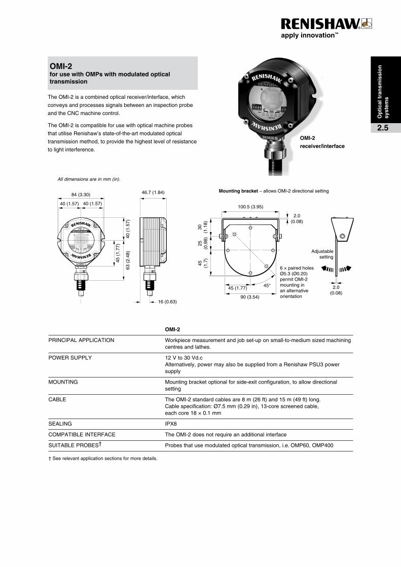
TheOMI-2isacombinedopticalreceiver/interface,which
conveysandprocessessignalsbetweenaninspectionprobe
andtheCNCmachinecontrol.
TheOMI-2iscompatibleforusewithopticalmachineprobes
thatutiliseRenishaw’sstate-of-the-artmodulatedoptical
transmissionmethod,toprovidethehighestlevelofresistance
tolightinterference.
OMI-2
PRINCIPALAPPLICATION Workpiecemeasurementandjobset-uponsmall-to-mediumsizedmachiningcentresandlathes.
POWERSUPPLY 12Vto30Vd.cAlternatively,powermayalsobesuppliedfromaRenishawPSU3powersupply
MOUNTING Mountingbracketoptionalforside-exitconfiguration,toallowdirectionalsetting
CABLE TheOMI-2standardcablesare8m(26ft)and15m(49ft)long.Cablespecification:Ø7.5mm(0.29in),13-corescreenedcable,eachcore18×0.1mm
SEALING IPX8
COMPATIBLEINTERFACE TheOMI-2doesnotrequireanadditionalinterface
SUITABLEPROBES† Probesthatusemodulatedopticaltransmission,i.e.OMP60,OMP400
†Seerelevantapplicationsectionsformoredetails.
OMI-2�for�use�with�OMPs�with�modulated�optical�transmission
All dimensions are in mm (in).
OMI-2�
receiver/interface
Probing�systems�for��CNC�machine�tools
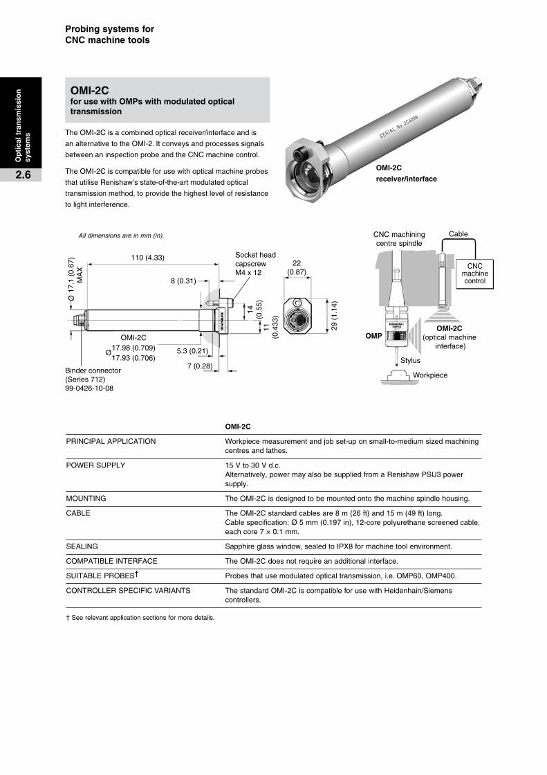
TheOMI-2Cisacombinedopticalreceiver/interfaceandis
analternativetotheOMI-2.Itconveysandprocessessignals
betweenaninspectionprobeandtheCNCmachinecontrol.
TheOMI-2Ciscompatibleforusewithopticalmachineprobes
thatutiliseRenishaw’sstate-of-the-artmodulatedoptical
transmissionmethod,toprovidethehighestlevelofresistance
tolightinterference.
OMI-2C�for�use�with�OMPs�with�modulated�optical�transmission
All dimensions are in mm (in).
OMI-2C�
receiver/interface
110(4.33)
8(0.31)
22(0.87)
29(
1.14
)
11
(0.4
33)
14(0
.55)
OMI-2C17.98(0.709)17.93(0.706)
5.3(0.21)
7(0.28)
SocketheadcapscrewM4x12
Ø
17.1
(0.
67)
MA
X
Ø
Binderconnector(Series712)99-0426-10-08
Stylus
CNCmachiningcentrespindle
Cable
Workpiece
CNCmachinecontrol
OMPOMI-2C
(opticalmachineinterface)
OMI-2C
PRINCIPALAPPLICATION Workpiecemeasurementandjobset-uponsmall-to-mediumsizedmachiningcentresandlathes.
POWERSUPPLY 15Vto30Vd.c.Alternatively,powermayalsobesuppliedfromaRenishawPSU3powersupply.
MOUNTING TheOMI-2Cisdesignedtobemountedontothemachinespindlehousing.
CABLE TheOMI-2Cstandardcablesare8m(26ft)and15m(49ft)long.Cablespecification:Ø5mm(0.197in),12-corepolyurethanescreenedcable,eachcore7×0.1mm.
SEALING Sapphireglasswindow,sealedtoIPX8formachinetoolenvironment.
COMPATIBLEINTERFACE TheOMI-2Cdoesnotrequireanadditionalinterface.
SUITABLEPROBES† Probesthatusemodulatedopticaltransmission,i.e.OMP60,OMP400.
CONTROLLERSPECIFICVARIANTS ThestandardOMI-2CiscompatibleforusewithHeidenhain/Siemenscontrollers.
†Seerelevantapplicationsectionsformoredetails.
Op
tica
l�tra
nsm
issi
on
�sy
stem
s
2.6

RMI�interface
44(1.73)
17.5(0.69)
2.0(0.08)
Blankingplugwithsealingring.
Theplugandsealfiteitherthesideorrearexitcablepositions.
4holesM5x13deepon80p.c.d.
45°
Whenusingrearexitcable,provideaØ25(1.0)holeinmounting
forclearance.
GrooveforrearexitOringseal
97(3.82)
46(1.81) 46(1.81)
45(
1.77
)50
(1.
97)
74(
2.91
)
TheRMIisacombinedtransmitterandreceiverforusewith
theRMP60radioprobe.
Itisdesignedtobeeasilymountedwithin,orcloseto,the
machine,resultinginaquickandsimpleinstallation.
TheRMP60RMIsystemisidealforretrofittingto
existingmachines.
AvisualindicationofsystemstatusisprovidedbyLEDs.
Statusiscontinuouslyupdatedandindicationisprovidedfor
start,lowbattery,probestatus,errorandsignalstrength.
RMI�interface�for�use�with�the�RMP60�probe
All dimensions are in mm (in).
RMI�
PRINCIPALAPPLICATION Workpiecemeasurementandjobset-uponmediumtolargehorizontal,verticalandgantry machiningcentres,5-axismachines,twinspindlemachinesandverticalturretlathes
TRANSMISSIONTYPE Frequencyhoppingspreadspectrumradio(FHSS)
CABLE Ø7.5mm(0.29in),13-corescreenedcable,eachcore18x0.1mm. TheRMIissuppliedwitha15mcableassemblyasstandard. 30mand50mcableassembliesarealsoavailable.
MOUNTING Anoptionalmountingbracketisavailable,allowingdirectionalsetting. TheRMIcablecanbereconfiguredforrearexit.
SEALING IPX8
COMPATIBLEINTERFACE TheRMIdoesnotrequireanadditionalinterface
SUITABLEPROBES† RMP60radiotransmissionprobe
†Seerelevantapplicationsectionsformoredetails.
Rad
io�t
ran
smis
sio
n��
syst
ems
2.7

19
(0.74)
32
(1.25)
36
(1.41)
22
(0.86)
26(
1.02
)26
(1.
02)
20
(0.78)
Ø20
(0.78)
Probing�systems�for��CNC�machine�tools
Ind
uct
ive�
tran
smis
sio
n�
syst
ems
2.8
TheIMMisaninductivemodulethatmay
beattachedtothespindlenoseofaCNC
machiningcentre.Thepreferredconfiguration
hasarearexitcable.
Analternativeconfigurationusesasideexit
cablewhichcanbesuppliedwithvarious
conduitstosuittheapplication.
TheIMMmayalsobefittedtothemain
castingattherearofatoolturretonaCNC
lathe.Inthisinstance,theunitiscylindrical
witharearexitcable.
Inductivetransmissionisnotrecommended
forretrofitinstallations.Machinebuilders
shouldcontacttheirRenishawsupplierfor
furtherdetails.
TheIMMisalsoavailablewithaceramic
faceforapplicationswhereswarfmaycause
erosiontothestandardface.
IMM
PRINCIPALAPPLICATION Machiningcentresandlathes
TRANSMISSIONTYPE Electromagneticinduction
INDUCTIVEMODULEAIRGAP 0.1mm(0.004in)to2.1mm(0.08in)
INDUCTIVEMODULEECCENTRICITY 2.0mm(0.08)max
CABLE Screened,3-core,7/0.2Standard Ø4.3mm(Ø0.17in)x5m(16.4ft)longExtension Various5.5m(18.0ft)to25.5m(83.6ft) Maxlengthpermitted=100m(328ft) Exposedcablesmustbelocatedinprotectiveconduit
CONDUIT(Sideexitunitsonly) Ø11mm(Ø0.43in)flexibleconduit Ø8mm(Ø0.31in)steelconduit
SEALING IPX8
COMPATIBLEINTERFACE¥ MI5
SUITABLEPROBES† MP1orMP3formachiningcentreapplications LP2forlatheapplications
¥SeeINTERFACESsectionformoredetails.†Seerelevantapplicationsectionsformoredetails.
All dimensions are in mm (in).
IMM
Opticalcentreline
90°
Transmission�angles
40
Opticalcentre
line
60°
15°
15°
30°
30°
45°
45°
75°
0°
60°
1(3.3)
2(6.5)
3(9.8)
4(13.1)
5(16.4)
60°
15°
15°
30°
30°
45°
45°
0°
1(3.3)
2(6.5)
3(9.8)
4(13.1)
5(16.4)60°
40
60°
15°
15°
30°
30°
45°
45°
0°
60°
1(3.3)
2(6.5)
3(9.8)
4(13.1)
5(16.4)
60°
15°
15°
30°
30°
45°
45°
75°
0°
60°
1(3.3)
2(6.5)
3(9.8)
4(13.1)
5(16.4)
Opticalcentre
line
75°
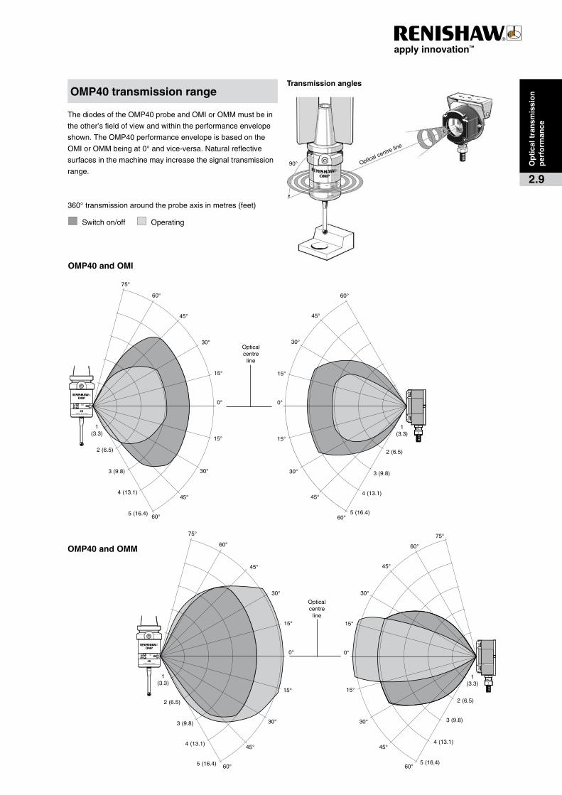
ThediodesoftheOMP40probeandOMIorOMMmustbein
theother’sfieldofviewandwithintheperformanceenvelope
shown.TheOMP40performanceenvelopeisbasedonthe
OMIorOMMbeingat0°andvice-versa.Naturalreflective
surfacesinthemachinemayincreasethesignaltransmission
range.
360°transmissionaroundtheprobeaxisinmetres(feet)
Switchon/off Operating
OMP40�transmission�range
OMP40�and�OMI
OMP40�and�OMM
Op
tica
l�tra
nsm
issi
on
��p
erfo
rman
ce
2.9
Opticalcentreline
90°
Transmission�angles
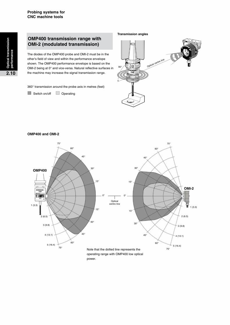
ThediodesoftheOMP400probeandOMI-2mustbeinthe
other’sfieldofviewandwithintheperformanceenvelope
shown.TheOMP400performanceenvelopeisbasedonthe
OMI-2beingat0°andvice-versa.Naturalreflectivesurfacesin
themachinemayincreasethesignaltransmissionrange.
360°transmissionaroundtheprobeaxisinmetres(feet)
Switchon/off Operating
OMP400�and�OMI-2
OMP400�transmission�range�with��OMI-2�(modulated�transmission)
OMP400
OMI-2
0°
Opticalcentreline
60°
45°
45°
15°
30°
30°
15°
60°
0°
60°
45°
45°
15°
30°
30°
15°
60°
75°
4(13.1)
3(9.8)
2(6.5)
1(3.3)
5(16.4)
4(13.1)
3(9.8)
2(6.5)
1(3.3)
5(16.4)75°
75°
75°Notethatthedottedlinerepresentsthe
operatingrangewithOMP400lowoptical
power.
Probing�systems�for��CNC�machine�tools
Op
tica
l�tra
nsm
issi
on
��p
erfo
rman
ce
2.10
Opticalcentreline
90°
Transmission�angles
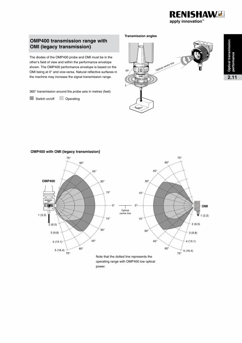
ThediodesoftheOMP400probeandOMImustbeinthe
other’sfieldofviewandwithintheperformanceenvelope
shown.TheOMP400performanceenvelopeisbasedonthe
OMIbeingat0°andvice-versa.Naturalreflectivesurfacesin
themachinemayincreasethesignaltransmissionrange.
360°transmissionaroundtheprobeaxisinmetres(feet)
Switchon/off Operating
OMP400�transmission�range�with��OMI�(legacy�transmission)
OMP400
OMI0°
Opticalcentreline
60°
45°
45°
15°
30°
30°
15°
60°
0°
60°
45°
45°
15°
30°
30°
15°
60°
75°
4(13.1)
3(9.8)
2(6.5)
1(3.3)
5(16.4)
4(13.1)
3(9.8)
2(6.5)
1(3.3)
5(16.4)75°
75°
75°
OMP400�with�OMI�(legacy�transmission)
Notethatthedottedlinerepresentsthe
operatingrangewithOMP400lowoptical
power.
Op
tica
l�tra
nsm
issi
on
per
form
ance
2.11
0°
OMP400
60°
45°
45°
15°
30°
30°
75°
15°
60°
OMM0°
60°
45°
45°
30°
30°
75°
15°
60°
4(13.1)
3(9.8)
2(6.6)
1(3.3)
5(16.4)
4(13.1)
3(9.8)
2(6.6)
1(3.3)
5(16.4)75° 75°
Opticalcentreline
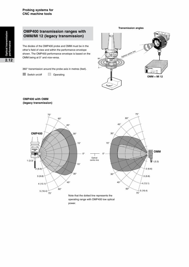
Notethatthedottedlinerepresentsthe
operatingrangewithOMP400lowoptical
power.
Probing�systems�for��CNC�machine�tools
Opticalcentreline
90°
Transmission�angles
OMM�+�MI�12
OMP400�with�OMM�(legacy�transmission)
OMP400�transmission�ranges�with�OMM/MI 12�(legacy�transmission)
ThediodesoftheOMP400probeandOMMmustbeinthe
other’sfieldofviewandwithintheperformanceenvelope
shown.TheOMP400performanceenvelopeisbasedonthe
OMMbeingat0°andvice-versa.
360°transmissionaroundtheprobeaxisinmetres(feet).
Switchon/off Operating
Op
tica
l�tra
nsm
issi
on
��p
erfo
rman
ce
2.12

Opticalcentreline
90°
Transmission�angles
60°
75°
45°
30°
15°
0°
15°
30°
45°
60°
75°
1(3.3)
2(6.5)
3(9.8)
4(13.1)
5(16.4)
6(19.9)
60°
75°
45°
30°
15°
0°
15°
45°
30°
60°
75°
1(3.3)
2(6.5)
3(9.8)
4(13.1)
5(16.4)
6(19.9)
Opticalcentre
lineOMP60
OMI-2
OMI-2
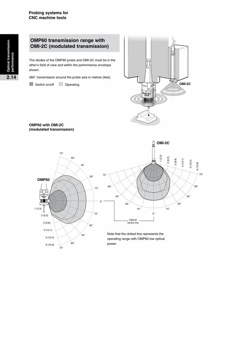
ThediodesoftheOMP60probeandOMI-2mustbeinthe
other’sfieldofviewandwithintheperformanceenvelope
shown.TheOMP60performanceenvelopeisbasedonthe
OMI-2beingat0°andvice-versa.
360°transmissionaroundtheprobeaxisinmetres(feet).
Switchon/off Operating
OMP60�transmission�range�with��OMI-2�(modulated�transmission)
OMP60�with�OMI-2��(modulated�transmission)
Notethatthedottedlinerepresentsthe
operatingrangewithOMP60lowoptical
power.
Op
tica
l�tra
nsm
issi
on
per
form
ance
2.13
OMP60
OMI-2C
0°
Opticalcentreline
60°
45°
45°
15°
30°
30°
15°
60°
0°
60°
45°45°
15°
30° 30°
15°
60°
75°
4(13.1)
3(9.8)
2(6.5)
1(3.3)
5(16.4)
75°6(19.9)
75°75°
1(3
.3)
2(6
.5)
3(9
.8)
4(1
3.1)
5(1
6.4)
6(1
9.9)
OMI-2C
Probing�systems�for��CNC�machine�tools
ThediodesoftheOMP60probeandOMI-2Cmustbeinthe
other’sfieldofviewandwithintheperformanceenvelope
shown.
360°transmissionaroundtheprobeaxisinmetres(feet).
Switchon/off Operating
OMP60�transmission�range�with��OMI-2C�(modulated�transmission)
OMP60�with�OMI-2C��(modulated�transmission)
Notethatthedottedlinerepresentsthe
operatingrangewithOMP60lowoptical
power.
Op
tica
l�tra
nsm
issi
on
��p
erfo
rman
ce
2.14
60°
75°
45°
30°
0°
15°
30°
45°
60°
75°
1(3.3)
2(6.5)
3(9.8)
4(13.1)
5(16.4)
6(19.9)
60°
75°
45°
30°
15°
0°
45°
30°
60°
75°
1(3.3)
2(6.5)
3(9.8)
4(13.1)
5(16.4)
6(19.9)
Opticalcentre
line
15°
15°
OMP60
OMI
Opticalcentreline
90°
Transmission�angles
OMI
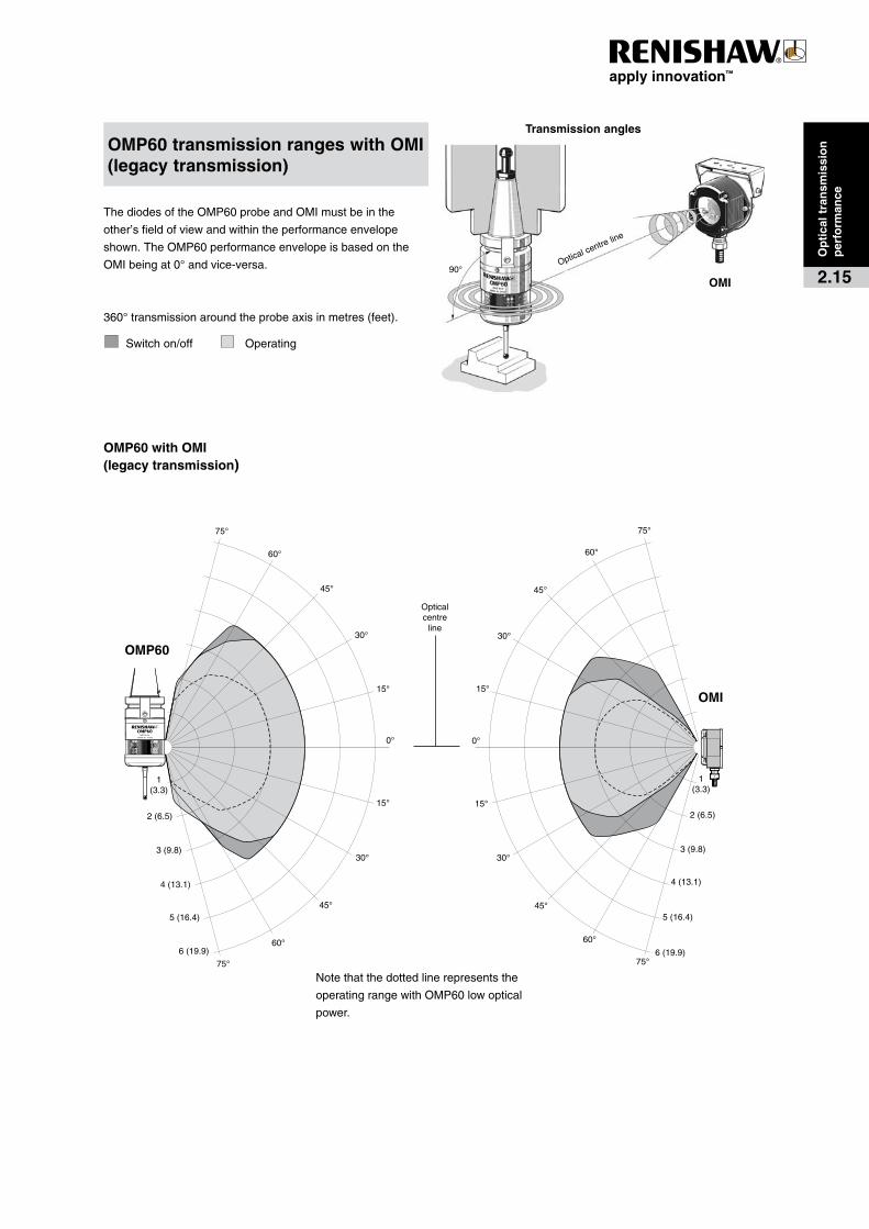
OMP60�transmission�ranges�with�OMI�(legacy�transmission)
ThediodesoftheOMP60probeandOMImustbeinthe
other’sfieldofviewandwithintheperformanceenvelope
shown.TheOMP60performanceenvelopeisbasedonthe
OMIbeingat0°andvice-versa.
360°transmissionaroundtheprobeaxisinmetres(feet).
Switchon/off Operating
Notethatthedottedlinerepresentsthe
operatingrangewithOMP60lowoptical
power.
OMP60�with�OMI�(legacy�transmission)
Op
tica
l�tra
nsm
issi
on
per
form
ance
2.15
Opticalcentreline
90°
Transmission�angles
60°
75°
45°
30°
0°
15°
30°
45°
60°
75°
1(3.3)
2(6.5)
3(9.8)
4(13.1)
5(16.4)
6(19.9)
60°
75°
45°
30°
15°
0°
45°
30°
60°
75°
1(3.3)
2(6.5)
3(9.8)
4(13.1)
5(16.4)
6(19.9)
Opticalcentre
line
15°
15°
OMP60
OMM
OMM�+�MI�12
Probing�systems�for��CNC�machine�tools
Op
tica
l�tra
nsm
issi
on
��p
erfo
rman
ce
2.16
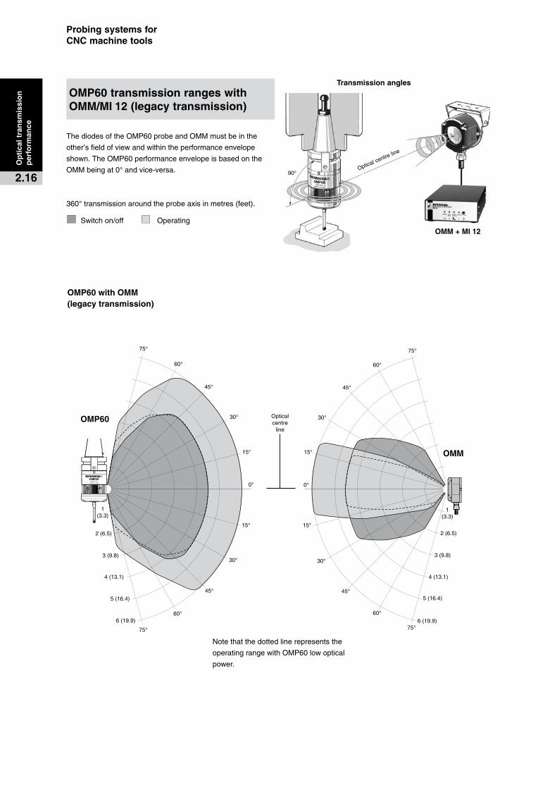
OMP60�with�OMM�(legacy�transmission)
OMP60�transmission�ranges�with�OMM/MI 12�(legacy�transmission)
ThediodesoftheOMP60probeandOMMmustbeinthe
other’sfieldofviewandwithintheperformanceenvelope
shown.TheOMP60performanceenvelopeisbasedonthe
OMMbeingat0°andvice-versa.
360°transmissionaroundtheprobeaxisinmetres(feet).
Switchon/off Operating
Notethatthedottedlinerepresentsthe
operatingrangewithOMP60lowoptical
power.
Transmission�angles
Opticalcentreline
35°
70°
Ver
tical
1(3.3)
2(6.5)
3(9.8)
0°
-15°
-30°
+60°
+15°
+30°+45°
+75°
+90° 0°
-15°
-30°-45° -60°
+60°
+15°
+30°
+45°
Opticalcentreline
1(3.3)
2(6.5)
3(9.8)
1(3.3)
2(6.5)3(9.8)
0°-15°
-30°
-45°
-60°
+60°
+15°+30°
+45°
+75°
+90°
0°
-15° -30°
-45°
-60°
+60°
+15°
+30°
+45°
Opticalcentreline
1(3.3)2(6.5)
3(9.8)
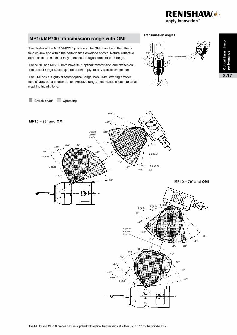
ThediodesoftheMP10/MP700probeandtheOMImustbeintheother’s
fieldofviewandwithintheperformanceenvelopeshown.Naturalreflective
surfacesinthemachinemayincreasethesignaltransmissionrange.
TheMP10andMP700bothhave360°opticaltransmissionand“switchon”.
Theopticalrangevaluesquotedbelowapplyforanyspindleorientation.
TheOMIhasaslightlydifferentopticalrangethanOMM,offeringawider
fieldofviewbutashortertransmit/receiverange.Thismakesitidealforsmall
machineinstallations.
Switchon/off Operating
TheMP10andMP700probescanbesuppliedwithopticaltransmissionateither35°or70°tothespindleaxis.
MP10/MP700�transmission�range�with�OMI
MP10�–�35°�and�OMI
MP10�–�70°�and�OMI
Op
tica
l�tra
nsm
issi
on
per
form
ance
2.17
Transmission�angles
Opticalcentreline
Ver
tical
35°
70°
1(3.3)
2(6.5)
3(9.8)
4(13.1)
5(16.4)
6(19.7)
0°
-15°
-30°
-45°
+60°
+15°
+30°+45°
+75°
+90°
0°
-15°
-30°-45° -60°
+60°
+15°
+30°
+45°
Opticalcentreline
2(6.5)3(9.8)
4(13.1)
5(16.4)6(19.7)
1(3.3)
2(6.5)3(9
.8)4(13.1)5(1
6.4)6(19.7)
0°
-15°
-30°
-45°
-60°
+60°
+15°+30°
+45°
+75°
+90°
0°
-15°-30°
-45°
-60°
+60°
+15°
+30°
+45°
Opticalcentreline
1(3.3)
2(6.5)
3(9.8)
4(13.1)
5(16.4)
6(19.7)
Probing�systems�for��CNC�machine�tools
Op
tica
l�tra
nsm
issi
on
per
form
ance
2.18
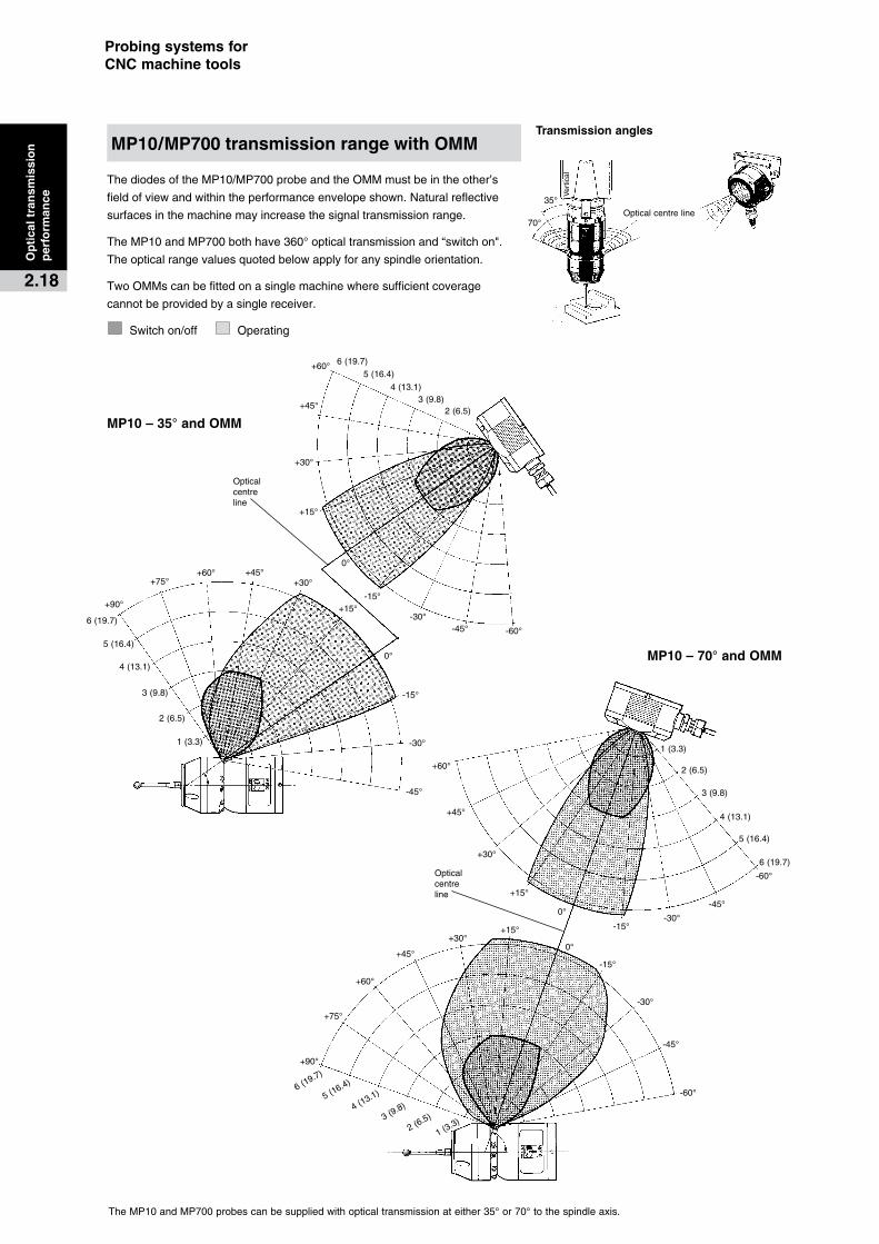
ThediodesoftheMP10/MP700probeandtheOMMmustbeintheother’s
fieldofviewandwithintheperformanceenvelopeshown.Naturalreflective
surfacesinthemachinemayincreasethesignaltransmissionrange.
TheMP10andMP700bothhave360°opticaltransmissionand“switchon".
Theopticalrangevaluesquotedbelowapplyforanyspindleorientation.
TwoOMMscanbefittedonasinglemachinewheresufficientcoverage
cannotbeprovidedbyasinglereceiver.
Switchon/off Operating
TheMP10andMP700probescanbesuppliedwithopticaltransmissionateither35°or70°tothespindleaxis.
MP10/MP700�transmission�range�with�OMM
MP10�–�35°�and�OMM
MP10�–�70°�and�OMM
Opticalcentreline
15°
1(3.3)
1.5(4.9)
2(6.5)
25(8.2)
3(9.8)
Opticalcentreline
-45°
-60°
0°
-15°
-30°
+60°
+75°
+90°
+45°
+30°
+15°
-45°
-60°
0°
-15°
-30°
+60°
+45°
+30°
+15°
1(3.3)
1.5(4.9)
2(6.5)
25(8.2)
3(9.8)
Opticalcentreline
1(3.3)
1.5(4.9)
2(6.5)
25(8.2)
3(9.8)
-45°
-60°
0°
-15°
-30°
+60°
+45°
+30°
+15°
-45°
-60°
0°
-15°
-30°
+60°
+75°
+90°
+45°
+30°
+15°
1(3.3)
1.5(4.9)
2(6.5)
25(8.2)
3(9.8)
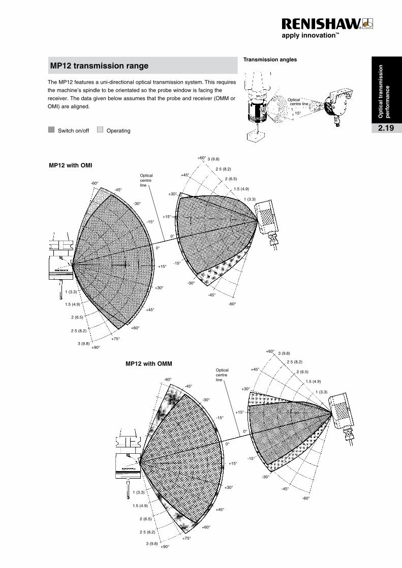
TheMP12featuresauni-directionalopticaltransmissionsystem.Thisrequires
themachine’sspindletobeorientatedsotheprobewindowisfacingthe
receiver.Thedatagivenbelowassumesthattheprobeandreceiver(OMMor
OMI)arealigned.
Switchon/off Operating
MP12�transmission�rangeTransmission�angles
MP12�with�OMM
MP12�with�OMI
Op
tica
l�tra
nsm
issi
on
��p
erfo
rman
ce
2.19
LTO2S
LTO2T/3T
LTO2
+60°
-45°
-60°
+45°
+30°
+15°
0°-15° -30°
-45°
+45°
+30°
+15°
-15°-30°
1(3.3) 2(6.5) 3(9.8)
Opticalcentreline
1(3.3)
2(6.5)
3(9.8)
-60°
+60°
4(13.1)
4(13.1)
+60°
-45°
-60°
+45°
+30°
+15°
0°
-15° -30°
-45°
+45°
+30°
+15°
-15°-30°
1(3.3) 2(6.5) 3(9.8)
Opticalcentreline
1(3.3)
2(6.5)
3(9.8)
4(13.1)
4(13.1)
-60°
+60°
Probing�systems�for��CNC�machine�tools
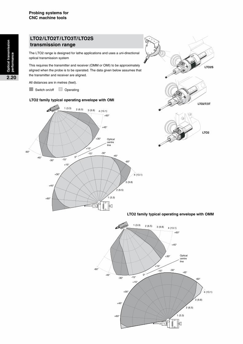
TheLTO2rangeisdesignedforlatheapplicationsandusesauni-directional
opticaltransmissionsystem
Thisrequiresthetransmitterandreceiver(OMMorOMI)tobeapproximately
alignedwhentheprobeistobeoperated.Thedatagivenbelowassumesthat
thetransmitterandreceiverarealigned.
Alldistancesareinmetres(feet).
Switchon/off Operating
LTO2�family�typical�operating�envelope�with�OMI
LTO2�family�typical�operating�envelope�with�OMM
LTO2/LTO2T/LTO3T/LTO2S��transmission�range
Op
tica
l�tra
nsm
issi
on
per
form
ance
2.20
Transmission�angles
CNC�MACHINE�CONTROL
75°
60°
45°
30°
15°
15°
30°
45°
60°
75°
45°
60°
75°
30°
15°
15°
30°
45°
60°
75°90°
5(16)
10(35)
15
(49)
75°
60°
45°
30°
15°
0°
15°
30°
45°
60°75°
15(49)
10(33)
5(16)
5(16)
10(33)
15(49)
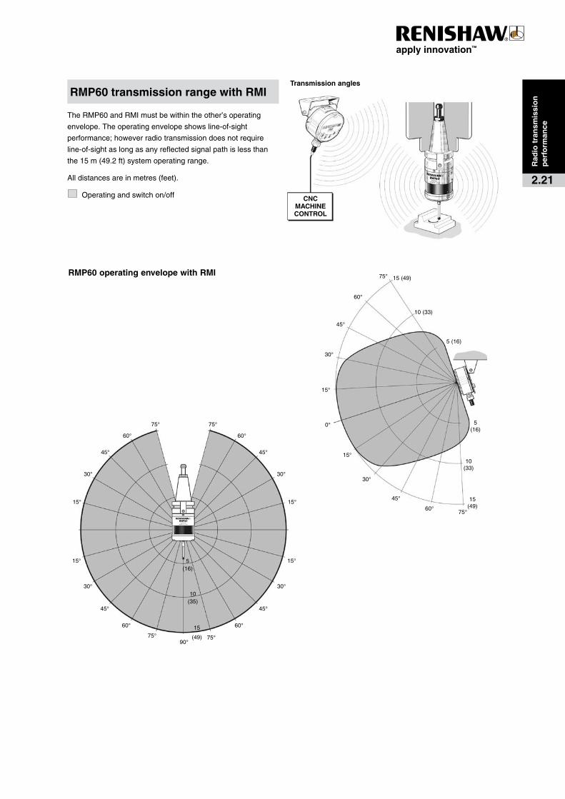
TheRMP60andRMImustbewithintheother’soperating
envelope.Theoperatingenvelopeshowsline-of-sight
performance;howeverradiotransmissiondoesnotrequire
line-of-sightaslongasanyreflectedsignalpathislessthan
the15m(49.2ft)systemoperatingrange.
Alldistancesareinmetres(feet).
Operatingandswitchon/off
RMP60�transmission�range�with�RMI
Rad
io�t
ran
smis
sio
n��
per
form
ance
2.21
RMP60�operating�envelope�with�RMI

Probing�systems�for��CNC�machine�tools
Applications
Renishawprobescanbeusedonmachining
centresandmillingmachinesforcomponent
settingandinspectionapplications.
Component�setting
Theprobeidentifiesthepositionoftheworkpiece,
automaticallyupdatingworkoffsets,andenablingpartstobe
maderightfirsttime.
Thiscanalsobeusedfor:
·� partidentificationforFMSinstallations.
·� componentlocationandalsomisloaddetectiontoavoidscrap.
·� excessmaterialidentificationtobringthecuttertothe
componentquicklyandsafely.
First-off�inspection
Inspectionofthefirstcomponentinabatchonthemachine
toolto:
·� reducethetimethemachineisidleawaitingfeedbackfrom
anoff-lineinspectiondevice.
·� correctanyerrorsautomatically.
In-process�inspection
Measurecomponentsfollowingroughmachiningto:
·� ensurecriticalfinalcutsarecorrect.
·� highlighterrorsbeforetheybecomefaults.
� Machine� Small� Medium� Large
� CNC�machining�centres
Vertical OMP40/MP12 RMP60/OMP60/MP10 RMP60
Horizontal OMP40/OMP60/MP10 RMP60/OMP60/MP10 RMP60
Highaccuracy MP700/OMP400 MP700/OMP400
Milling�machines
CNCmachines MP15 MP11 MP11
Manualmachines Jobcontactprobe
Thefrequencyofinspectionwilldependonthevalueofthe
componentandconfidenceinthemachine’sperformance.
Inspectionofkeyfeaturesonhighvaluecomponentsis
usuallyessentialforunmannedmachiningoperations.
Post�process�inspection
Inspectionofthepartoncethemachiningiscompleted
canbeusedto:
·� provideinformationtocertifythatthecomponentiswithinits
specification.
·� recordpartdimensionsforstatisticalprocesscontrol.
Probe�selection
Onmachiningcentres,probesrequirearemotetransmission
system(seesection2,Transmissionselection).
Thefollowingpagesshowsomeofthemostcommontypes
ofinspectionprobeapplicationsonmachiningcentres:
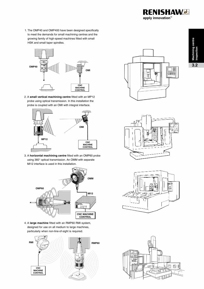
1.TheOMP40�and�OMP400havebeendesignedspecifically
tomeetthedemandsforsmallmachiningcentresandthe
growingfamilyofhigh-speedmachinesfittedwithsmall
HSKandsmalltaperspindles.
2.Asmall,verticalmachiningcentrefittedwithanMP12
compactinspectionprobeusingopticaltransmission.
3.AhorizontalmachiningcentrefittedwithanOMP60probe
featuring360°opticaltransmission.TheOMP60isalso
suitableforlargerverticalmachines.
4.TheRMP60probehasbeendesignedforuseonall
mediumtolargemachines,particularlywhennonline-of-
sightisrequired.
Othercommonapplicationsinclude:
·� Wherehighprecisionisrequired,Renishaw’sOMP400and
MP700‘straingauge’probesarerecommended.Using
opticaltransmission,bothprobesareidealforinspectionof
contouredcomponentsandcomponentsrequiringlongstyli
reach.
·� Onmillingmachines,simplehard-wiredprobesand
‘jobcontact’probesareavailable.
Mac
hin
ing
�cen
tre�
insp
ecti
on
3.1
CNC�machining�centre�and�milling�machine�inspection�probing�systems
CNC��MACHINE�CONTROL
OMP40
OMI
CNC��MACHINE�CONTROL
MP12
OMI
CNC��MACHINE�CONTROL
RMP60RMI
CNC�MACHINE�CONTROL
MI12
OMM
OMP60
1.TheOMP40andOMP400havebeendesignedspecifically
tomeetthedemandsforsmallmachiningcentresandthe
growingfamilyofhigh-speedmachinesfittedwithsmall
HSKandsmalltaperspindles.
3.Ahorizontal�machining�centrefittedwithanOMP60probe
using360°opticaltransmission.AnOMMwithseparate
MI12interfaceisusedinthisinstallation.
4.Alarge�machinefittedwithanRMP60RMIsystem,
designedforuseonallmediumtolargemachines,
particularlywhennon-line-of-sightisrequired.
2.Asmall�vertical�machining�centrefittedwithanMP12
probeusingopticaltransmission.Inthisinstallationthe
probeiscoupledwithanOMIwithintegralinterface.
Mac
hin
ing
�cen
tre
insp
ecti
on
3.2
11°6
(0.24)
50(1.97)
190.75)
Ø40(1.57)
11°
Probing�systems�for��CNC�machine�tools
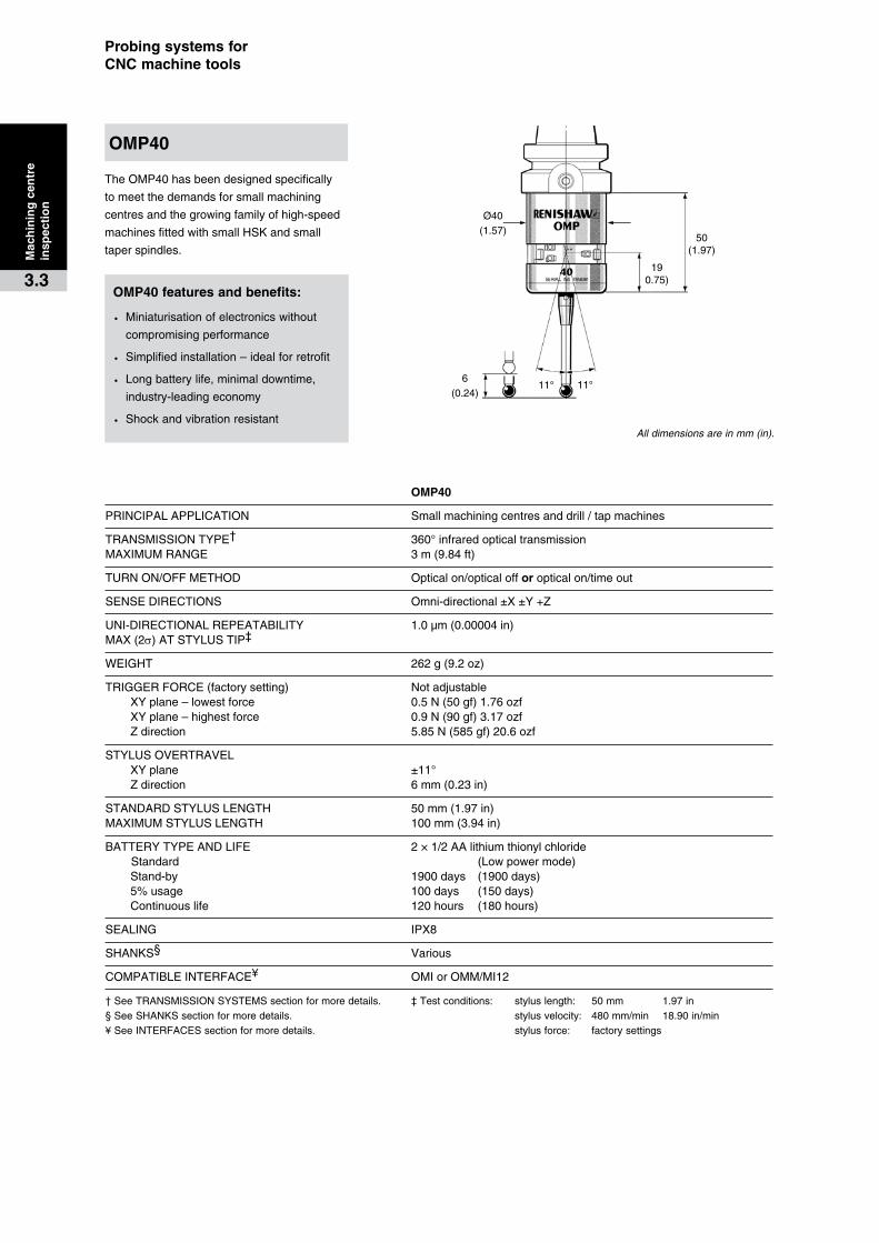
TheOMP40hasbeendesignedspecifically
tomeetthedemandsforsmallmachining
centresandthegrowingfamilyofhigh-speed
machinesfittedwithsmallHSKandsmall
taperspindles.
� �� OMP40
PRINCIPALAPPLICATION Smallmachiningcentresanddrill/tapmachines
TRANSMISSIONTYPE† 360°infraredopticaltransmissionMAXIMUMRANGE 3m(9.84ft)
TURNON/OFFMETHOD Opticalon/opticalofforopticalon/timeout
SENSEDIRECTIONS Omni-directional±X±Y+Z
UNI-DIRECTIONALREPEATABILITY 1.0µm(0.00004in)MAX(2s)ATSTYLUSTIP‡
WEIGHT 262g(9.2oz)
TRIGGERFORCE(factorysetting) Notadjustable XYplane–lowestforce 0.5N(50gf)1.76ozf XYplane–highestforce 0.9N(90gf)3.17ozf Zdirection 5.85N(585gf)20.6ozf
STYLUSOVERTRAVEL XYplane ±11° Zdirection 6mm(0.23in)
STANDARDSTYLUSLENGTH 50mm(1.97in)MAXIMUMSTYLUSLENGTH 100mm(3.94in)
BATTERYTYPEANDLIFE 2×1/2AAlithiumthionylchloride Standard (Lowpowermode) Stand-by 1900days (1900days) 5%usage 100days (150days) Continuouslife 120hours (180hours)
SEALING IPX8
SHANKS§ Various
COMPATIBLEINTERFACE¥ OMIorOMM/MI12
†SeeTRANSMISSIONSYSTEMSsectionformoredetails. ‡Testconditions: styluslength: 50mm 1.97in§SeeSHANKSsectionformoredetails. stylusvelocity: 480mm/min 18.90in/min¥See INTERFACESsectionformoredetails. stylusforce: factorysettings
All dimensions are in mm (in).
OMP40�features�and�benefits:
· Miniaturisationofelectronicswithout
compromisingperformance
· Simplifiedinstallation–idealforretrofit
· Longbatterylife,minimaldowntime,
industry-leadingeconomy
· Shockandvibrationresistant
OMP40
Mac
hin
ing
�cen
tre
insp
ecti
on
3.3

11°6
(0.24)
50.0
(1
.97)
Ø40(1.57)
11°
TheOMP400hasbeendesignedspecificallyforuseonsmallhighspeedmachiningcentresandmouldanddieapplications,especiallywherecompactsizeandhigh3Daccuracymeasurementofcomplexsurfacesisdemanded.
TheOMP400iscompatiblewithallRenishawreceivers,allowingittooperateinmodulatedmodewithOMI-2andOMI-2Cforverygoodresistancetolightinterference.Itwillalsooperateinlegacymode,enablingexistingprobeuserstoupgradetotakeadvantageofthiscompactandhighaccuracyprobe.
All dimensions are in mm (in).
� � OMP400
PRINCIPALAPPLICATION Smallhighspeedmachinesandmouldanddieapplications
TRANSMISSIONTYPE† 360°infraredopticaltransmissionMAXIMUMRANGE OMP400OMI-2 4metres(13.1ft) OMP400OMI 3metres(9.84ft) OMP400OMM 4metres(13.1ft)
TURNON/OFFMETHOD Opticalon/opticalofforopticalon/timeout
SENSEDIRECTIONS Omni-directional:±X,±Y,+Z
UNI-DIRECTIONALREPEATABILITY 0.25µm(0.00001in)MAX(2s)ATSTYLUSTIP‡
PRE-TRAVELVARIATION‡ XYplane ±0.25µm(±0.00001in) XYZ(variationfromatruesphere) ±1.0µm(±0.00004in)
WEIGHT 262g(9.2oz)
TRIGGERFORCE(factorysetting) Notadjustable XYplane–constantforce 0.02N(2gf)0.07ozf +Zdirection 0.15N(15gf)0.53ozf
STYLUSOVERTRAVEL XYplane ±11° +Zdirection 6mm(0.24in)
STANDARDSTYLUSLENGTH* 50mm(1.97in)MAXIMUMSTYLUSLENGTH* 200mm(7.87in)
BATTERYTYPEANDLIFE 2×1/2AAlithiumthionylchloride Standard (Lowpowermode) Stand-by 1900days (1900days) 5%usage 100days (150days) Continuouslife 120hours (180hours)
SEALING IPX8
SHANKS§ Various
COMPATIBLEINTERFACE¥ OMM/MI12,OMI,OMI-2andOMI-2C
†SeeTRANSMISSIONSYSTEMSsectionformoredetails. ‡Testconditions: styluslength: 50mm 1.97in
*M4carbonfibrestyliarerecommended.SeeSTYLI section. stylusvelocity: 480mm/min 18.90in/min§SeeSHANKSsectionformoredetails. stylusforce: factorysettings¥See INTERFACESsectionformoredetails.
OMP400
OMP400�features�and�benefits:
· Superior3Dmeasurementperformanceproberepeatabilityof0.25µm(2s)
· Providesimprovedaccuracyevenwithlongstyli
· IncorporatespatentedRENGAGE™sensingtechnologytoprovidehighaccuracywithimproveddurability
· Designedforuseonsmallhighspeedand5-axismachines
· Highresistancetoshockandvibration
19(0.75)
Mac
hin
ing
�cen
tre
insp
ecti
on
3.4
Ø63(2.48)
76(2.99)
19(0.75)
18° 18°11(0.43)
Probing�systems�for��CNC�machine�tools
Mac
hin
ing
�cen
tre�
insp
ecti
on
3.5
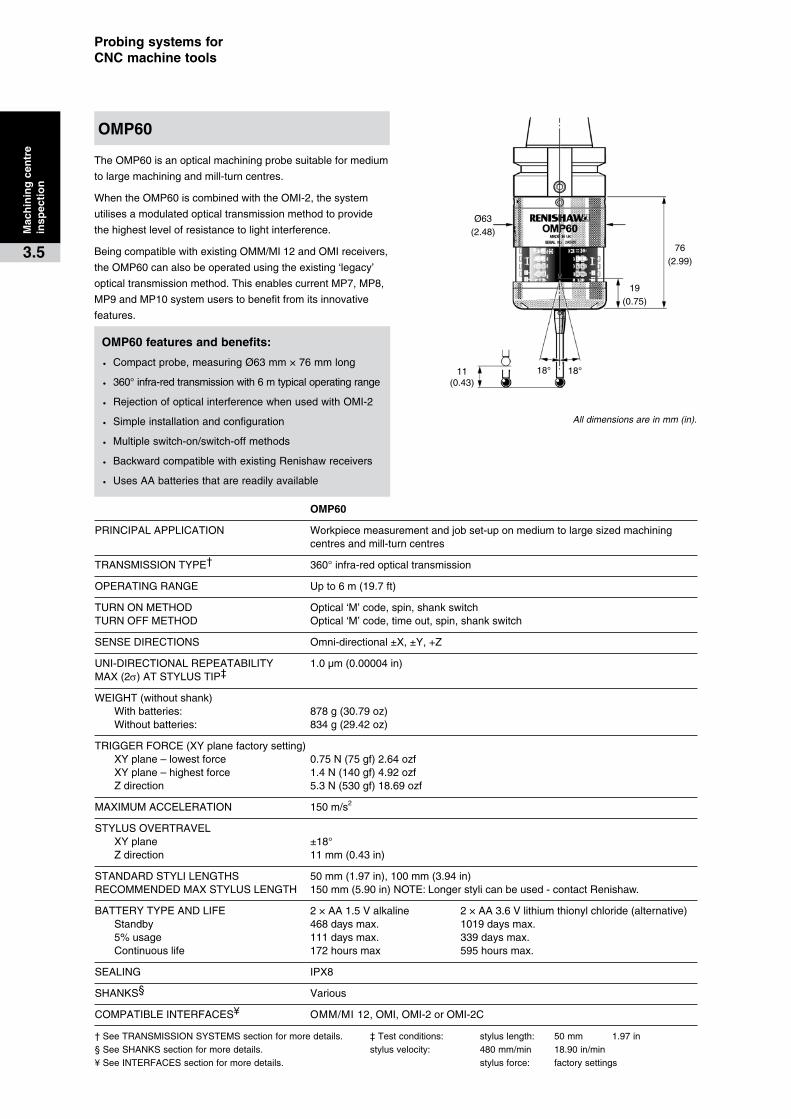
TheOMP60isanopticalmachiningprobesuitableformedium
tolargemachiningandmill-turncentres.
WhentheOMP60iscombinedwiththeOMI-2,thesystem
utilisesamodulatedopticaltransmissionmethodtoprovide
thehighestlevelofresistancetolightinterference.
BeingcompatiblewithexistingOMM/MI 12andOMIreceivers,
theOMP60canalsobeoperatedusingtheexisting‘legacy’
opticaltransmissionmethod.ThisenablescurrentMP7,MP8,
MP9andMP10systemuserstobenefitfromitsinnovative
features.
� ��� OMP60
PRINCIPALAPPLICATION Workpiecemeasurementandjobset-uponmediumtolargesizedmachining centresandmill-turncentres
TRANSMISSIONTYPE† 360°infra-redopticaltransmission
OPERATINGRANGE Upto6m(19.7ft)
TURNONMETHOD Optical‘M’code,spin,shankswitchTURNOFFMETHOD Optical‘M’code,timeout,spin,shankswitch
SENSEDIRECTIONS Omni-directional±X,±Y,+Z
UNI-DIRECTIONALREPEATABILITY 1.0µm(0.00004in)MAX(2s)ATSTYLUSTIP‡
WEIGHT(withoutshank) Withbatteries: 878g(30.79oz) Withoutbatteries: 834g(29.42oz)
TRIGGERFORCE(XYplanefactorysetting) XYplane–lowestforce 0.75N(75gf)2.64ozf XYplane–highestforce 1.4N(140gf)4.92ozf Zdirection 5.3N(530gf)18.69ozf
MAXIMUMACCELERATION 150m/s2
STYLUSOVERTRAVEL XYplane ±18° Zdirection 11mm(0.43in)
STANDARDSTYLILENGTHS 50mm(1.97in),100mm(3.94in)RECOMMENDEDMAXSTYLUSLENGTH 150mm(5.90in)NOTE:Longerstylicanbeused-contactRenishaw.
BATTERYTYPEANDLIFE 2×AA1.5Valkaline 2×AA3.6Vlithiumthionylchloride(alternative) Standby 468daysmax. 1019daysmax. 5%usage 111daysmax. 339daysmax. Continuouslife 172hoursmax 595hoursmax.
SEALING IPX8
SHANKS§ Various
COMPATIBLEINTERFACES¥ OMM/MI12,OMI,OMI-2orOMI-2C
†SeeTRANSMISSIONSYSTEMSsectionformoredetails. ‡Testconditions: styluslength: 50mm 1.97in§SeeSHANKSsectionformoredetails. stylusvelocity: 480mm/min 18.90in/min¥See INTERFACESsectionformoredetails. stylusforce: factorysettings
OMP60�features�and�benefits:
· Compactprobe,measuringØ63mm×76mmlong
· 360°infra-redtransmissionwith6mtypicaloperatingrange
· RejectionofopticalinterferencewhenusedwithOMI-2
· Simpleinstallationandconfiguration
· Multipleswitch-on/switch-offmethods
· BackwardcompatiblewithexistingRenishawreceivers
· UsesAAbatteriesthatarereadilyavailable
OMP60
All dimensions are in mm (in).
76(2.99)
19(0.75)
18° 18°
Ø63
(2.48)
All dimensions are in mm (in).
11(0.43)
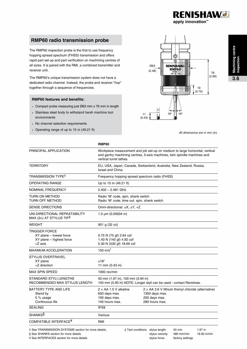
TheRMP60inspectionprobeisthefirsttousefrequency
hoppingspreadspectrum(FHSS)transmissionandoffers
rapidpartset-upandpartverificationonmachiningcentresof
allsizes.ItispairedwiththeRMI,acombinedtransmitterand
receiverunit.
TheRMP60’suniquetransmissionsystemdoesnothavea
dedicatedradiochannel.Instead,theprobeandreceiver“hop”
togetherthroughasequenceoffrequencies.
� ���� RMP60
PRINCIPALAPPLICATION Workpiecemeasurementandjobset-uponmediumtolargehorizontal,vertical andgantrymachiningcentres,5-axismachines,twinspindlemachinesand verticalturretlathes.
TERRITORY EU,USA,Japan,Canada,Switzerland,Australia,NewZealand,Russia, IsraelandChina.
TRANSMISSIONTYPE† Frequencyhoppingspreadspectrumradio(FHSS)
OPERATINGRANGE Upto15m(49.21ft)
NOMINALFREQUENCY 2.402–2.481GHz
TURNONMETHOD Radio‘M’code,spin,shankswitchTURNOFFMETHOD Radio‘M’code,timeout,spin,shankswitch
SENSEDIRECTIONS Omni-directional:±X,±Y,+Z
UNI-DIRECTIONALREPEATABILITY 1.0µm(0.00004in)MAX(2s)ATSTYLUSTIP‡
WEIGHT 901g(32oz)
TRIGGERFORCE XYplane–lowestforce 0.75N(75gf)2.64ozf XYplane–highestforce 1.40N(140gf)4.92ozf +Zaxis 5.30N(530gf)18.69ozf
MAXIMUMACCELERATION 150m/s2
STYLUSOVERTRAVEL XYplane ±18° +Zdirection 11mm(0.43in)
MAXSPINSPEED 1000rev/min
STANDARDSTYLILENGTHS 50mm(1.97in),100mm(3.94in)RECOMMENDEDMAXSTYLUSLENGTH 150mm(5.90in)NOTE:Longerstylicanbeused-contactRenishaw.
BATTERYTYPEANDLIFE 2×AA1.5Valkaline 2×AA3.6Vlithiumthionylchloride(alternative) Standby 650daysmax. 1300daysmax. 5%usage 100daysmax. 200daysmax. Continuouslife 140hoursmax. 280hoursmax.
SEALING IPX8
SHANKS§ Various
COMPATIBLEINTERFACE¥ RMI
†SeeTRANSMISSIONSYSTEMSsectionformoredetails. ‡Testconditions styluslength: 50mm 1.97in§SeeSHANKSsectionformoredetails. stylusvelocity: 480mm/min 18.90in/min¥See INTERFACESsectionformoredetails stylusforce: factorysettings
RMP60�radio�transmission�probe
RMP60�features�and�benefits:
· CompactprobemeasuringjustØ63mmx76mminlength
· Stainlesssteelbodytowithstandharshmachinetool
environments
· Nochannelselectionrequirements
· Operatingrangeofupto15m(49.21ft)
Mac
hin
ing
�cen
tre
insp
ecti
on
3.6
17.5°8(0.31)
21.5
(0.8
5)70
°O
MP
116
.2(
4.57
)
35°
OM
P1
16.7
(4.
59)
Ø62(2.44)
17.5°
Probing�systems�for��CNC�machine�tools
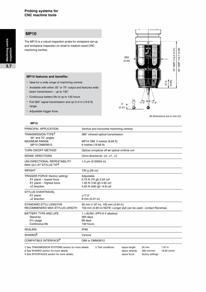
TheMP10isarobustinspectionprobeforworkpieceset-up
andworkpieceinspectiononsmalltomediumsizedCNC
machiningcentres.
� �MP10
PRINCIPALAPPLICATION Verticalandhorizontalmachiningcentres
TRANSMISSIONTYPE† 360°infraredopticaltransmission 35°and70°anglesMAXIMUMRANGE MP10OMI 3metres(9.84ft) MP10OMM/MI12 6metres(19.69ft)
TURNON/OFFMETHOD Opticalon/opticalofforopticalon/timeout
SENSEDIRECTIONS Omni-directional:±X,±Y,+Z
UNI-DIRECTIONALREPEATABILITY 1.0µm(0.00004in)MAX(2s)ATSTYLUSTIP‡
WEIGHT 730g(26oz)
TRIGGERFORCE(factorysetting) Adjustable XYplane–lowestforce 0.75N(75gf)2.64ozf XYplane–highestforce 1.40N(140gf)4.92ozf +Zdirection 4.20N(420gf)14.8ozf
STYLUSOVERTRAVEL XYplane ±17.5° +Zdirection 8mm(0.31in)
STANDARDSTYLILENGTHS 50mm(1.97in),100mm(3.94in)RECOMMENDEDMAXSTYLUSLENGTH 150mm(5.90in)NOTE:Longerstylicanbeused-contactRenishaw.
BATTERYTYPEANDLIFE 1×6LR61(PP39Valkaline) Stand-by 365days 5%usage 98days Continuouslife 140hours
SEALING IPX8
SHANKS§ Various
COMPATIBLEINTERFACE¥ OMIorOMM/MI12
†SeeTRANSMISSIONSYSTEMSsectionformoredetails. ‡Testconditions: styluslength: 50mm 1.97in§SeeSHANKSsectionformoredetails. stylusvelocity: 480mm/min 18.90in/min¥See INTERFACESsectionformoredetails. stylusforce: factorysettings
All dimensions are in mm (in).
MP10
Mac
hin
ing
�cen
tre
insp
ecti
on
3.7
MP10�features�and�benefits:
· Idealforawiderangeofmachiningcentres
· Availablewitheither35°or70°outputandfeatureswide
beamtransmission–upto130°
· Continuousbatterylifeofupto140hours
· Full360°signaltransmissionandupto6m(19.6ft)
range.
· Adjustabletriggerforce
62(2.44)
Ø63(2.48)
11(0.43)
13
(0.5
4)
15° 15°
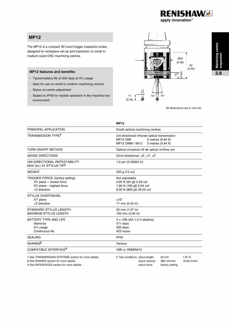
TheMP12isacompact3Dtouch-triggerinspectionprobe,
designedforworkpieceset-upandinspectiononsmallto
mediumsizedCNCmachiningcentres.
� MP12
PRINCIPALAPPLICATION Smallverticalmachiningcentres
TRANSMISSIONTYPE† Uni-directionalinfraredopticaltransmission MP12OMI 3metres(9.84ft) MP12OMM/MI12 3metres(9.84ft)
TURNON/OFFMETHOD Opticalon/opticalofforopticalon/timeout
SENSEDIRECTIONS Omni-directional:±X,±Y,+Z
UNI-DIRECTIONALREPEATABILITY 1.0µm(0.00004in)MAX(2s)ATSTYLUSTIP‡
WEIGHT 420g(15oz)
TRIGGERFORCE(factorysetting) Notadjustable XYplane–lowestforce 0.65N(65gf)2.29ozf XYplane–highestforce 1.60N(160gf)5.64ozf +Zdirection 8.00N(800gf)28.22ozf
STYLUSOVERTRAVEL XYplane ±15° +Zdirection 11mm(0.43in)
STANDARDSTYLUSLENGTH 50mm(1.97in)MAXIMUMSTYLUSLENGTH 100mm(3.94in)
BATTERYTYPEANDLIFE 4×LR6(AA1.5Valkaline) Stand-by 471days 5%usage 205days Continuouslife 425hours
SEALING IPX8
SHANKS§ Various
COMPATIBLEINTERFACE¥ OMIorOMM/MI12
†SeeTRANSMISSIONSYSTEMSsectionformoredetails. ‡Testconditions: styluslength: 50mm 1.97in§SeeSHANKSsectionformoredetails. stylusvelocity: 480mm/min 18.90in/min¥See INTERFACESsectionformoredetails. stylusforce: factorysetting
MP12
Mac
hin
ing
�cen
tre�
insp
ecti
on
3.8MP12�features�and�benefits:
· Typicalbatterylifeof205daysat5%usage
· Idealforuseonsmalltomediummachiningcentres
· Styluson-centreadjustment
· SealedtoIPX8forreliableoperationinthemachinetool
environment
All dimensions are in mm (in).
16.5°
11(0.43)
24.5
(0.9
6)70
°O
MP
116
.2(
4.57
)
35°
OM
P1
16.7
(4.
59)
Ø62(2.44)
16.5°
Probing�systems�for��CNC�machine�tools
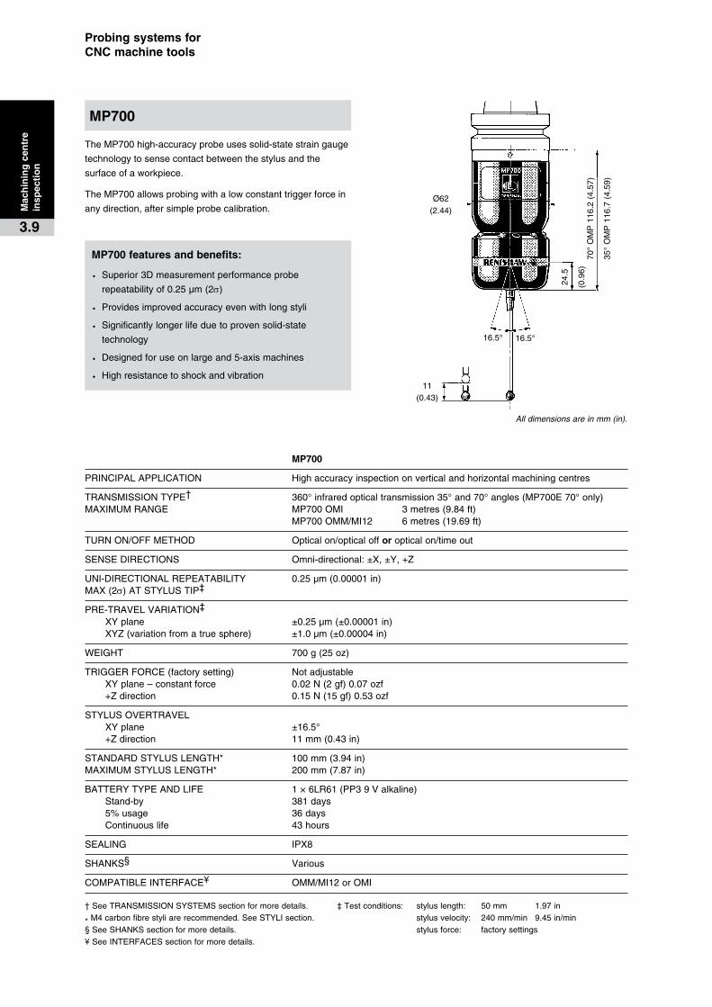
TheMP700high-accuracyprobeusessolid-statestraingauge
technologytosensecontactbetweenthestylusandthe
surfaceofaworkpiece.
TheMP700allowsprobingwithalowconstanttriggerforcein
anydirection,aftersimpleprobecalibration.
All dimensions are in mm (in).
� � MP700
PRINCIPALAPPLICATION Highaccuracyinspectiononverticalandhorizontalmachiningcentres
TRANSMISSIONTYPE† 360°infraredopticaltransmission35°and70°angles(MP700E70°only)MAXIMUMRANGE MP700OMI 3metres(9.84ft) MP700OMM/MI12 6metres(19.69ft)
TURNON/OFFMETHOD Opticalon/opticalofforopticalon/timeout
SENSEDIRECTIONS Omni-directional:±X,±Y,+Z
UNI-DIRECTIONALREPEATABILITY 0.25µm(0.00001in)MAX(2s)ATSTYLUSTIP‡
PRE-TRAVELVARIATION‡ XYplane ±0.25µm(±0.00001in) XYZ(variationfromatruesphere) ±1.0µm(±0.00004in)
WEIGHT 700g(25oz)
TRIGGERFORCE(factorysetting) Notadjustable XYplane–constantforce 0.02N(2gf)0.07ozf +Zdirection 0.15N(15gf)0.53ozf
STYLUSOVERTRAVEL XYplane ±16.5° +Zdirection 11mm(0.43in)
STANDARDSTYLUSLENGTH* 100mm(3.94in)MAXIMUMSTYLUSLENGTH* 200mm(7.87in)
BATTERYTYPEANDLIFE 1×6LR61(PP39Valkaline) Stand-by 381days 5%usage 36days Continuouslife 43hours
SEALING IPX8
SHANKS§ Various
COMPATIBLEINTERFACE¥ OMM/MI12orOMI
†SeeTRANSMISSIONSYSTEMSsectionformoredetails. ‡Testconditions: styluslength: 50mm 1.97in
*M4carbonfibrestyliarerecommended.SeeSTYLI section. stylusvelocity: 240mm/min 9.45in/min§SeeSHANKSsectionformoredetails. stylusforce: factorysettings¥See INTERFACESsectionformoredetails.
MP700
MP700�features�and�benefits:
· Superior3Dmeasurementperformanceprobe
repeatabilityof0.25µm(2s)
· Providesimprovedaccuracyevenwithlongstyli
· Significantlylongerlifeduetoprovensolid-state
technology
· Designedforuseonlargeand5-axismachines
· Highresistancetoshockandvibration
Mac
hin
ing
�cen
tre�
insp
ecti
on
3.9
28.5°
17(0.67)
L
88(3.46)
Ø82
(3.23)
28.5°
R
25.5(1.00)
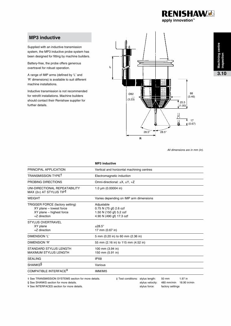
Suppliedwithaninductivetransmission
system,theMP3inductiveprobesystemhas
beendesignedforfittingbymachinebuilders.
Battery-free,theprobeoffersgenerous
overtravelforrobustoperation.
ArangeofIMParms(definedby‘L’and
‘R’dimensions)isavailabletosuitdifferent
machineinstallations.
Inductivetransmissionisnotrecommended
forretrofitinstallations.Machinebuilders
shouldcontacttheirRenishawsupplierfor
furtherdetails.
� � MP3�inductive
PRINCIPALAPPLICATION Verticalandhorizontalmachiningcentres
TRANSMISSIONTYPE† Electromagneticinduction
PROBINGDIRECTIONS Omni-directional:±X,±Y,+Z
UNI-DIRECTIONALREPEATABILITY 1.0µm(0.00004in)MAX(2s)ATSTYLUSTIP‡
WEIGHT VariesdependingonIMParmdimensions
TRIGGERFORCE(factorysetting) Adjustable XYplane–lowestforce 0.75N(75gf)2.6ozf XYplane–highestforce 1.50N(150gf)5.2ozf +Zdirection 4.90N(490gf)17.3ozf
STYLUSOVERTRAVEL XYplane ±28.5° +Zdirection 17mm(0.67in)
DIMENSION‘L’ 5mm(0.20in)to60mm(2.36in)
DIMENSION‘R’ 55mm(2.16in)to115mm(4.52in)
STANDARDSTYLUSLENGTH 100mm(3.94in)MAXIMUMSTYLUSLENGTH 150mm(5.91in)
SEALING IPX8
SHANKS§ Various
COMPATIBLEINTERFACE¥ IMM/MI5
†SeeTRANSMISSIONSYSTEMSsectionformoredetails. ‡Testconditions: styluslength: 50mm 1.97in§SeeSHANKSsectionformoredetails. stylusvelocity: 480mm/min 18.90in/min¥See INTERFACESsectionformoredetails. stylusforce: factorysettings
MP3�inductive
All dimensions are in mm (in).
Mac
hin
ing
�cen
tre
insp
ecti
on
3.10
17.5°
8(0.31)
21.5(0.84)
75(2.95)
Ø60(2.36)
17.5°
Probing�systems�for��CNC�machine�tools
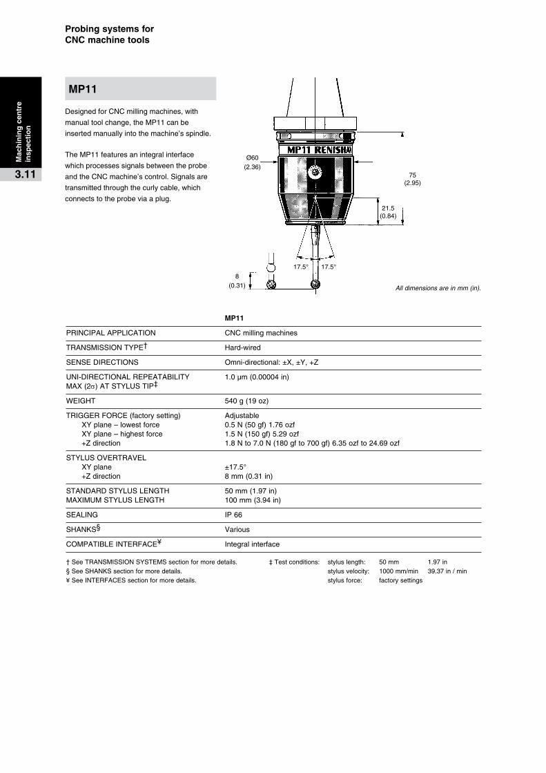
DesignedforCNCmillingmachines,with
manualtoolchange,theMP11canbe
insertedmanuallyintothemachine’sspindle.
TheMP11featuresanintegralinterface
whichprocessessignalsbetweentheprobe
andtheCNCmachine’scontrol.Signalsare
transmittedthroughthecurlycable,which
connectstotheprobeviaaplug.
� � MP11
PRINCIPALAPPLICATION CNCmillingmachines
TRANSMISSIONTYPE† Hard-wired
SENSEDIRECTIONS Omni-directional:±X,±Y,+Z
UNI-DIRECTIONALREPEATABILITY 1.0µm(0.00004in)MAX(2s)ATSTYLUSTIP‡
WEIGHT 540g(19oz)
TRIGGERFORCE(factorysetting) Adjustable XYplane–lowestforce 0.5N(50gf)1.76ozf XYplane–highestforce 1.5N(150gf)5.29ozf +Zdirection 1.8Nto7.0N(180gfto700gf)6.35ozfto24.69ozf
STYLUSOVERTRAVEL XYplane ±17.5° +Zdirection 8mm(0.31in)
STANDARDSTYLUSLENGTH 50mm(1.97in)MAXIMUMSTYLUSLENGTH 100mm(3.94in)
SEALING IP66
SHANKS§ Various
COMPATIBLEINTERFACE¥ Integralinterface
†SeeTRANSMISSIONSYSTEMSsectionformoredetails. ‡Testconditions: styluslength: 50mm 1.97in§SeeSHANKSsectionformoredetails. stylusvelocity: 1000mm/min 39.37in/min¥See INTERFACESsectionformoredetails. stylusforce: factorysettings
All dimensions are in mm (in).
MP11
Mac
hin
ing
�cen
tre�
insp
ecti
on
3.11
5(0.20)
42.75(1.68)
Ø28(1.10)
15(0.59)
15(0.59)
65.5(2.58)
JC30C
5(0.20)
42.75(1.68)
Ø28(1.10)
15(0.59)
15(0.59)
65.5(2.58)
JCP1-M�and�JCP1-I
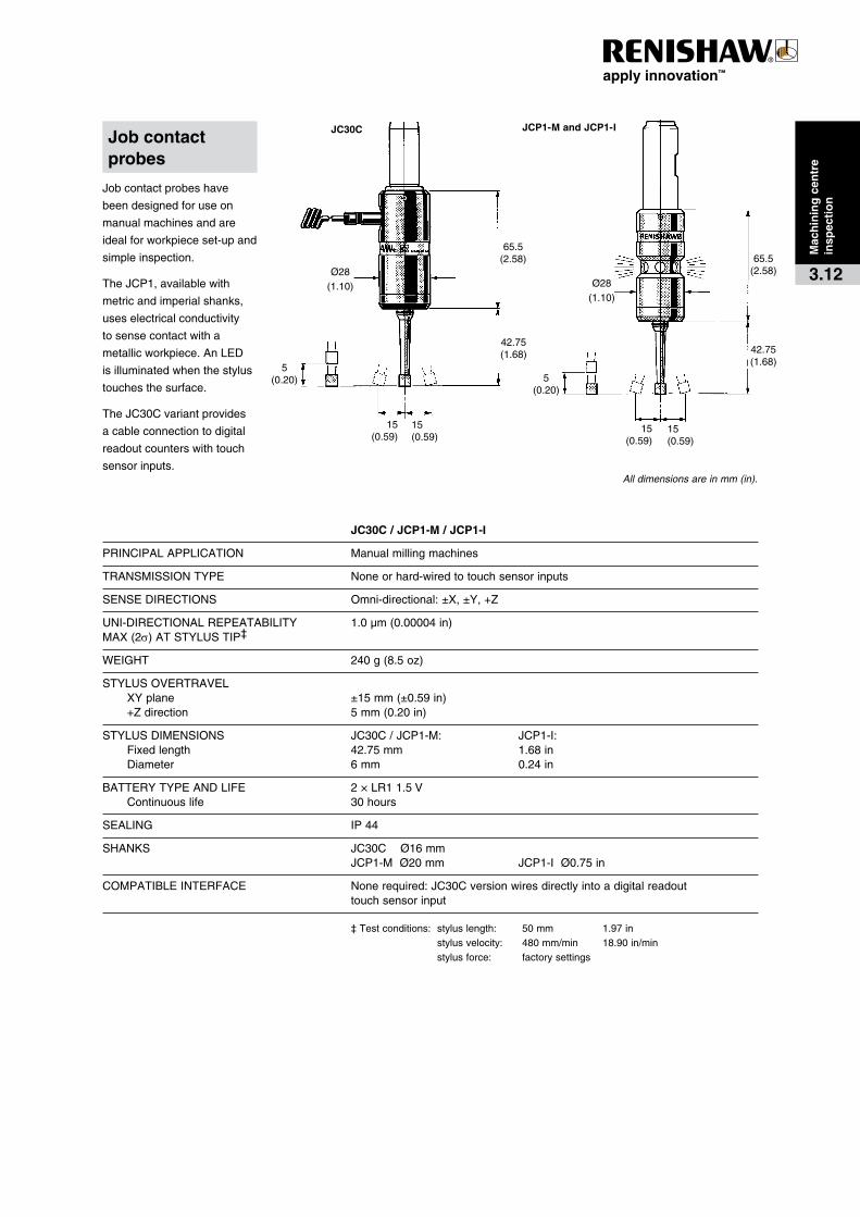
Jobcontactprobeshave
beendesignedforuseon
manualmachinesandare
idealforworkpieceset-upand
simpleinspection.
TheJCP1,availablewith
metricandimperialshanks,
useselectricalconductivity
tosensecontactwitha
metallicworkpiece.AnLED
isilluminatedwhenthestylus
touchesthesurface.
TheJC30Cvariantprovides
acableconnectiontodigital
readoutcounterswithtouch
sensorinputs.
� � JC30C�/�JCP1-M�/�JCP1-I
PRINCIPALAPPLICATION Manualmillingmachines
TRANSMISSIONTYPE Noneorhard-wiredtotouchsensorinputs
SENSEDIRECTIONS Omni-directional:±X,±Y,+Z
UNI-DIRECTIONALREPEATABILITY 1.0µm(0.00004in)MAX(2s)ATSTYLUSTIP‡
WEIGHT 240g(8.5oz)
STYLUSOVERTRAVEL XYplane ±15mm(±0.59in) +Zdirection 5mm(0.20in)
STYLUSDIMENSIONS JC30C/JCP1-M: JCP1-I: Fixedlength 42.75mm 1.68in Diameter 6mm 0.24in
BATTERYTYPEANDLIFE 2×LR11.5V Continuouslife 30hours
SEALING IP44
SHANKS JC30CØ16mm JCP1-MØ20mm JCP1-IØ0.75in
COMPATIBLEINTERFACE Nonerequired:JC30Cversionwiresdirectlyintoadigitalreadouttouchsensorinput
‡Testconditions: styluslength: 50mm 1.97in stylusvelocity: 480mm/min 18.90in/min stylusforce: factorysettings
Job�contact�probes
All dimensions are in mm (in).
Mac
hin
ing
�cen
tre
insp
ecti
on
3.12

Probing�systems�for��CNC�machine�tools
Applications
Renishawprobescanbeusedonmachining
centresfortoolsetting,toolverificationand
toolbreakagedetectionapplications.
Tool�setting
Toolsaredrivenagainsttheprobe’sstylus
withthetooleitherstaticorrotating:
·� Staticlengthsettingfordrills,tapsetc.
·� Rotatinglengthsettingforfacemillsand
otherlargecutters.
·� Rotatingdiametersettingforslotdrills,
boringbarsetc.
Tool�verification
Toollengthsanddiameterscanbechecked
beforeusetoguardagainsterrorsintool
selection.
Tool�breakage�detection
Rapidcheckingoftoollengthstoensurethat
toolsarestillintactaftermachining.
Probe�selection
Onatypicalmachiningcentre,atoolsettingprobecanbelocatedonthebedofthemachine.
However,morecomplexmachinesmay
requireanarmtointroducetheprobetothe
tools.
Thefollowingpageshowssomeofthemost
commontoolsettingprobeapplicationson
machiningcentres.
1.Atypicalverticalmachiningcentrefitted
withaTS27Rcompacttoolsettingprobe.
Thissimpleprobingsystemusesahard-
wiredtransmission.
2.Atypicalverticalmachiningcentrefitted
withafixedNC4non-contacttoolsetting
system.Thissystemincludesanadjuster
packforsimplealignmenttothemachine’s
axes.AlsoavailableistheNC3–a
compactnon-contacttoolsetterandbroken
tooldetectionsystem–andtheNC2,which
providesbrokentooldetection.
3.ATRS1non-contactbrokentooldetection
devicefittedtoatypicalverticalmachining
centre.Thissimpledevicewiresdirectlyinto
themachinecontroller.
AlsoavailableistheTRS1-Sforshort
rangeapplicationsonsmallmachining
centres.
4.AHPMAautomatictoolsettingarmfittedto
ahorizontalmachiningcentrewithamulti-
palletchanger.Thissolutionisidealfor
FMSapplications.FordetailsaboutHPMA
refertotheCNClathetoolsettingprobing
systemssection.
InadditiontorotaryarmsliketheHPMA,
Renishawcanalsoprovidearangeof
customisedtoolsettingsolutions.Refertothe
CustomProductsandAccessoriessectionfor
moredetails.
TS27R�contact�tool�setter
Mac
hin
ing
�cen
tre
too
l�set
tin
g/b
reak
age
4.1
Application� Probing�system�Verticalorhorizontal TS27Rmachinewithfixedbed TRS1/NC3/ NC4
Horizontalmachinewith HPMA/TRS1/multi-palletchanger NC4
CNC�machining�centre�tool�setting�and�breakage�detection�probing�systems

CNC�MACHINE�CONTROLM18/MI8-4
TS27R
CNC�MACHINE�CONTROL
HPMA
TSI�3/3C
CNC�MACHINE�CONTROL
NC4
NCi-4
1.Avertical�machining�centre�fittedwitha
TS27Rtoolsettingprobe.TheTS27Ris
alsoavailablewithstylitosuithorizontal
machiningcentreapplications.
2.Avertical�machining�centrefittedwith
afixedNC4non-contacttoolsetting
system,usinglaser-basedtransmitterand
receiverunits.NC4isalsoavailableasa
separatesystem.
3.AtypicalFMS�machinefittedwithaHPMA
automatictoolsetting.TheHPMAprovides
anautomatedsystemwithwhichthetool
settingprobecanbeintroducedtothetools
exactlywhenrequired.
Mac
hin
ing
�cen
tre�
too
l�set
tin
g/b
reak
age
4.2

73(2.87)
67(2.64)
4.5(0.18)
19.8(0.78)flat
5(0.20)
72(2.83)
3(0.12)
Ø4.7(0.19)
68(2.68)
83(3.27)
32(1.26)
38(1.50)
14.5(0.57)
Probing�systems�for��CNC�machine�tools
PRINCIPALAPPLICATION High-speednon-contacttoolbreakagedetectiononVMCandHMCmachines
LASERTYPE Visibleredlight<1mW670nm.ConformstoAmerican(21CRF1040.10and 1040.11exceptfordeviationspursuanttoLaserNoticeNo.50datedJuly26,2001) andEuropean(IEC60825-1:1993+A1:1997+A2:2001)lasersafetystandards
WORKINGTEMPERATURE 5°Cto50°C
STORAGETEMPERATURE -10°Cto70°C
LIFE Testedto>1millionon/offcycles.
MINIMUMTOOLDIAMETER Ø1mmbrightdrillat2m(6.56ft)andØ0.5mmbrightdrillat0.3m(0.984ft), dependentoninstallation,set-upandtooltype/condition.
PNEUMATICSUPPLY Ø4mmairpipe.Recommendedairpressure:2bar(29psi)to4.5bar(65.25psi), dependentonairpipelength. AirsupplytotheTRS1airregulatorunitmustconformtoISO8573-1:Class5 particlesandmoisture-free. AirsupplytotheTRS1unitmustconformtoISO8573-1:Airqualityofclass1.7.2.
WEIGHT 0.75kg(1.65lb),including10mofcable.
DIMENSIONS Height:83mm(3.27in) Width:38mm(1.50in) Depth:73mm(2.87in)
INPUTVOLTAGE Inputvoltage11Vdcto30Vdc.
CURRENTCONSUMPTION Typicallylessthan45mA.
CABLE 5-coreplusscreencable. Eachcore18/0.1insulated.Ø5.0mm(0.20in)x10m(32ft)
OUTPUT Solidstaterelay(SSR)normally-open/normally-closedcontactmax. 40mA(fusedat50mA).
SEALING SealedtoIPX8withairon
MOUNTING MountingbracketprovidedwithM4mountingholes. AlternativemountingarrangementprovidedbyM4holesintheproducthousing.
TRS1�Single-sided�tool�breakage�detection
TRS1�features�and�benefits:
· Costeffective,fastandreliable
· Featuresnewtoolrecognitiontechnology
· Ultra-quickdetection.Toolspends
approximately1secondinthelaser
beam
· Simpleinstallationandsetup
Mac
hin
ing
�cen
tre
too
l�bre
akag
e�d
etec
tio
n
4.3
Conventionalnon-contactbrokentool
detectionsystemsdependonthelaserbeam
beingblocked(toolOK)ornotblocked(tool
broken).
TheTRS1isdifferent.Itcontainsuniquetool
recognitiontechnologythatcandistinguish
betweenthetoolorcoolantandswarf.TRS1
respondstothepatternoflightreflectedfrom
thetool,offeringbenefitsoverconventional
systems.Itisfastandreliableunderreal
machiningconditions.
Thesingleunitmeansinstallationisquickand
easyandthedevicecanbemountedoutside
oftheworkingenvironment,savingvaluable
spaceonthetable.
All dimensions are in mm (in).
40(
1.58
)
60(
2.36
)
120
(4.7
2)
Bea
m h
eigh
t
104
(4.0
9)
44(
1.73
)
300(11.81)
225(8.89)
Ø30(1.18)
Ø30(1.18)
70(2.76)
18(0.71)
Systemseparation(m)
2si
gma
repe
atab
ility
(±
µm)
Forguidancepurposesonly
Note:Thetrendlineiscalculatedfromtheaverage2sigmarepeatabilityvaluesfrom20NC4systems
TX
RX
77(
3.03
)
Bea
m h
eigh
t
61(2
.40)
8(0.31)
AØ30
(1.18)Ø30
(1.18)
B
C
31(
1.22
)Ø
30(1
.18)
Compact�fixed�system�–�F115�and�F230�models
RX
TX
Ø30(1.18)
31(
1.22
)Ø
30(
1.18
)
Ø30(1.18)
23(0.91)
77(
3.03
)
Bea
m h
eigh
t
61(2
.40)
8(0.31) 33.5
(1.32)
95(3.74)
Compact�fixed�system�–�F95�model
Modular�fixed�system
Ø24(0.95)acrossflats Ø26(1.02)
35(
1.38
)
19(
0.75
)
5.4(0.21)
Ø30(1.18)
Separate�system
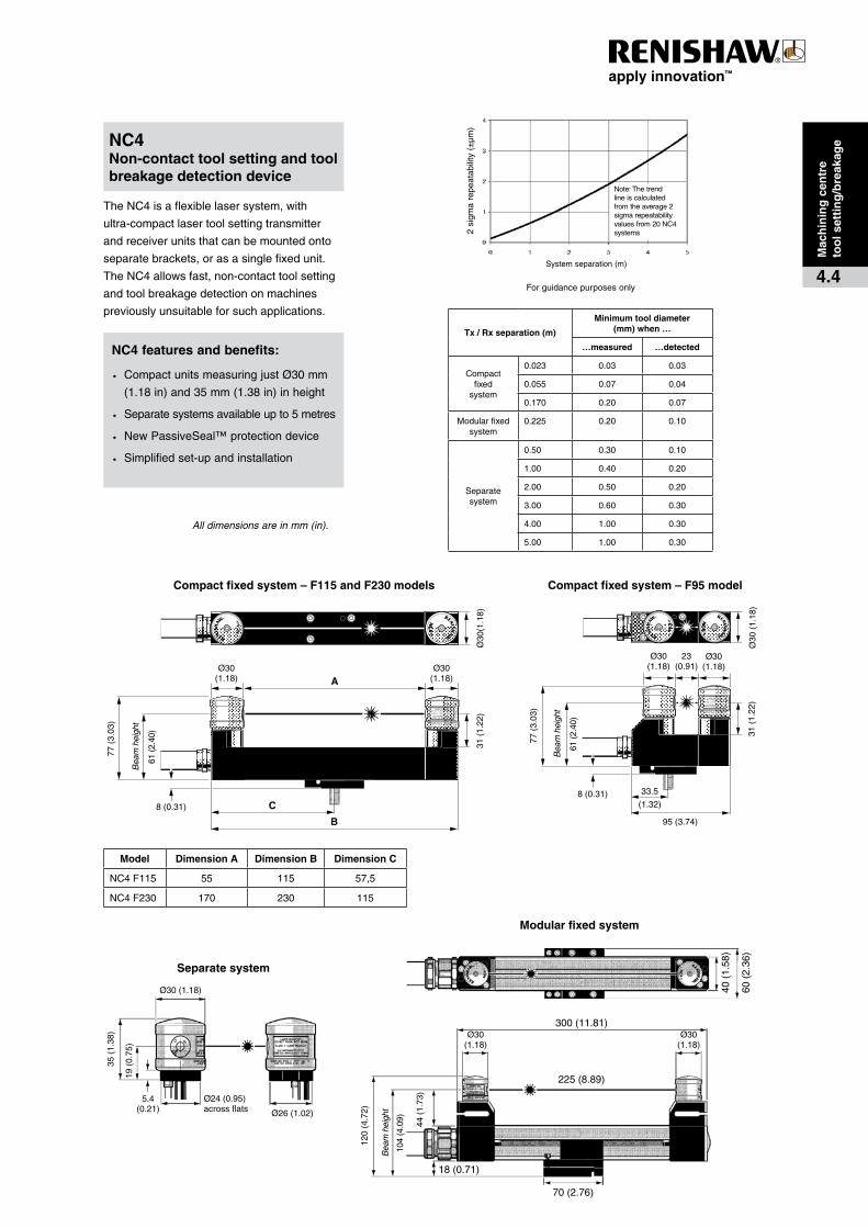
Model Dimension�A Dimension�B Dimension�C
NC4F115 55 115 57,5
NC4F230 170 230 115
TheNC4isaflexiblelasersystem,with
ultra-compactlasertoolsettingtransmitter
andreceiverunitsthatcanbemountedonto
separatebrackets,orasasinglefixedunit.
TheNC4allowsfast,non-contacttoolsetting
andtoolbreakagedetectiononmachines
previouslyunsuitableforsuchapplications.
NC4�Non-contact�tool�setting�and�tool�breakage�detection�device
Mac
hin
ing
�cen
tre�
too
l�set
tin
g/b
reak
age
4.4
All dimensions are in mm (in).
NC4�features�and�benefits:
· CompactunitsmeasuringjustØ30mm
(1.18in)and35mm(1.38in)inheight
· Separatesystemsavailableupto5metres
· NewPassiveSeal™protectiondevice
· Simplifiedset-upandinstallation
Tx�/�Rx�separation�(m)
Minimum�tool�diameter�(mm)�when�…
…measured …detected
Compactfixed
system
0.023 0.03 0.03
0.055 0.07 0.04
0.170 0.20 0.07
Modularfixedsystem
0.225 0.20 0.10
Separatesystem
0.50 0.30 0.10
1.00 0.40 0.20
2.00 0.50 0.20
3.00 0.60 0.30
4.00 1.00 0.30
5.00 1.00 0.30
Probing�systems�for��CNC�machine�tools
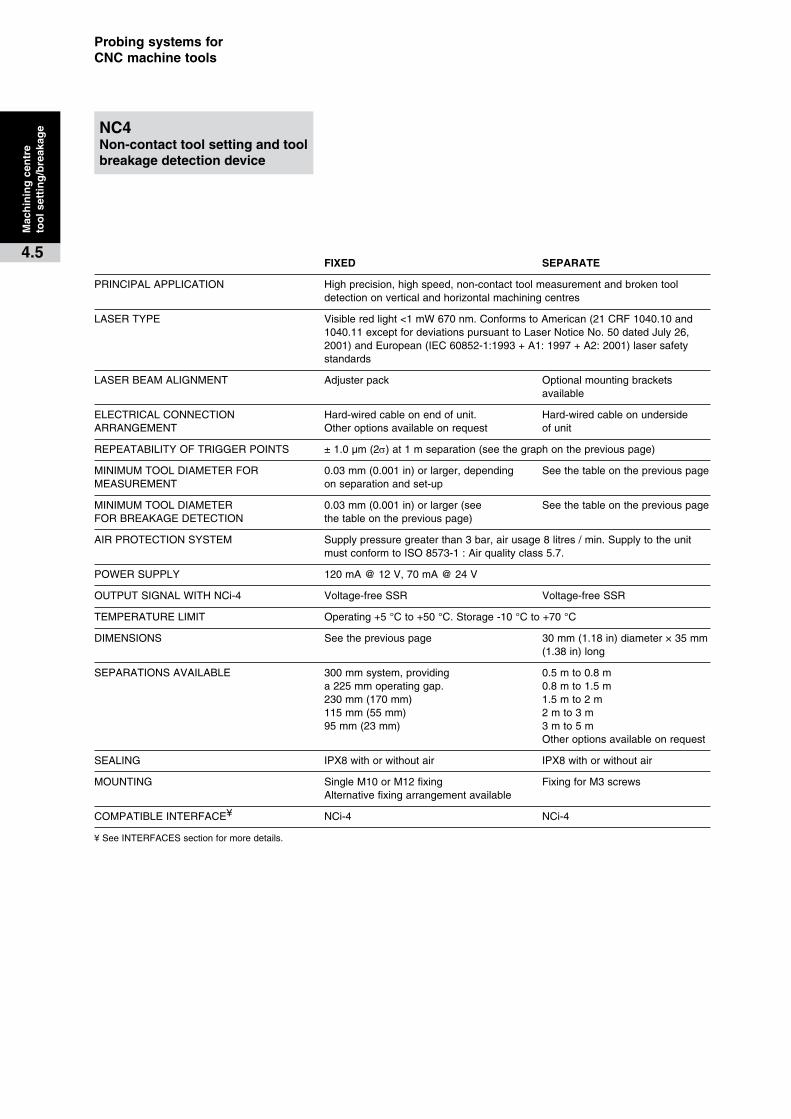
� FIXED� SEPARATE
PRINCIPALAPPLICATION Highprecision,highspeed,non-contacttoolmeasurementandbrokentool detectiononverticalandhorizontalmachiningcentres
LASERTYPE Visibleredlight<1mW670nm.ConformstoAmerican(21CRF1040.10and1040.11exceptfordeviationspursuanttoLaserNoticeNo.50datedJuly26,2001)andEuropean(IEC60852-1:1993+A1:1997+A2:2001)lasersafetystandards
LASERBEAMALIGNMENT Adjusterpack Optionalmountingbrackets available
ELECTRICALCONNECTION Hard-wiredcableonendofunit. Hard-wiredcableonundersideARRANGEMENT Otheroptionsavailableonrequest ofunit
REPEATABILITYOFTRIGGERPOINTS ±1.0µm(2s)at1mseparation(seethegraphonthepreviouspage)
MINIMUMTOOLDIAMETERFOR 0.03mm(0.001in)orlarger,depending SeethetableonthepreviouspageMEASUREMENT onseparationandset-up
MINIMUMTOOLDIAMETER 0.03mm(0.001in)orlarger(see SeethetableonthepreviouspageFORBREAKAGEDETECTION thetableonthepreviouspage)
AIRPROTECTIONSYSTEM Supplypressuregreaterthan3bar,airusage8litres/min.Supplytotheunit mustconformtoISO8573-1:Airqualityclass5.7.
POWERSUPPLY 120mA@12V,70mA@24V
OUTPUTSIGNALWITHNCi-4 Voltage-freeSSR Voltage-freeSSR
TEMPERATURELIMIT Operating+5°Cto+50°C.Storage-10°Cto+70°C
DIMENSIONS Seethepreviouspage 30mm(1.18in)diameter×35mm (1.38in)long
SEPARATIONSAVAILABLE 300mmsystem,providing 0.5mto0.8m a225mmoperatinggap. 0.8mto1.5m 230mm(170mm) 1.5mto2m 115mm(55mm) 2mto3m 95mm(23mm) 3mto5m Otheroptionsavailableonrequest
SEALING IPX8withorwithoutair IPX8withorwithoutair
MOUNTING SingleM10orM12fixing FixingforM3screwsAlternativefixingarrangementavailable
COMPATIBLEINTERFACE¥ NCi-4 NCi-4
¥SeeINTERFACESsectionformoredetails.
Mac
hin
ing
�cen
tre�
too
l�set
tin
g/b
reak
age
4.5
NC4�Non-contact�tool�setting�and�tool�breakage�detection�device

77(3.03) 69
(2.
72)
34
(1.3
4)
80(3.15)
38(1.50)135(5.31)
29(1.14)
26(1.02)
25(0.98)33
.5
(1.3
2)
TheNC3isacompact2-axisnon-contact
toolsettingsystem,withbrokentooldetection
capability.
Toolsassmallas0.2mmdiametercanbe
measuredanywherealongthelaserbeam.
Set-upissimplerthanfocusedlasersystems
asthereisnofocalpointtoidentify.
Itishard-wiredtotheNCi-4interfaceunit,
whichfeaturesaunique'driprejectionmode'.
This'driprejection'featureoffersprotection
againstunwantedtriggersignals.
TheNC3offersimprovedrepeatability,
reductioninairconsumptionandanimproved
rapidtool-breakagedetectioncycleandwith
fasteroperation,givesgreaterrepeatability.
� NC3
PRINCIPALAPPLICATION High-precision/high-speed,non-contacttoolsettingandtool breakagedetection
LASERTYPE Visibleredlight<1mW670nm.ConformstoAmerican(21CRF1040.10and 1040.11exceptfordeviationspursuanttoLaserNoticeNo.50datedJuly26, 2001)andEuropean(IEC60852-1:1993+A1:1997+A2:2001)lasersafety standards
LASERBEAMALIGNMENT Adjusterpack–supplied.Optionsavailable.
ELECTRICALCONNECTION Hard-wiredARRANGEMENT
REPEATABILITYOFTRIGGERPOINTS ±0.15µm(6µin)2s
MINIMUMTOOLDIAMETERFOR Ø0.2mm(0.008in)MEASUREMENT
MINIMUMTOOLDIAMETERFOR Ø0.1mm(0.004in)orlargerBREAKAGEDETECTION
AIRPROTECTIONSYSTEM Supplypressuregreaterthan3bar,airusage6litres/min.Supplymust conformtoISO8573-1:Airqualityclass5.7.Nylonpipingincluded.
POWERSUPPLY 12Vto30V,120mA.
POWERUPTIME <0.5seconds
TEMPERATURELIMIT Operating+5°Cto+50°C Storage-10°Cto+70°C
OUTSIDELENGTH/INTERNAL 135mm(5.31in)/80mm(3.15in)TRANSMITTERANDRECEIVERSEPARATION
SEALING IPX8
MOUNTING SingleM10/M12fixing.M4mountingholesalsoprovided
COMPATIBLEINTERFACE¥ NCi-4
¥SeeINTERFACESsectionformoredetails.
NC3�compact�laser�system
NC3�features�and�benefits:
· Impressiverepeatabilityof±0.15µm(2s)
· Highspeedbrokentooldetectioncycle
· MeasuretoolsofØ0.2mmandlarger.
· DetectbrokentoolsassmallasØ0.1mm
Mac
hin
ing
�cen
tre
too
l�set
tin
g/b
reak
age
4.6
All dimensions are in mm (in).
5.5(0.21)
Ø63.5
(2.50)
106(4.17)
93.7
5(3
.69)
10°10°
81.7
5(3
.22)
Probing�systems�for��CNC�machine�tools
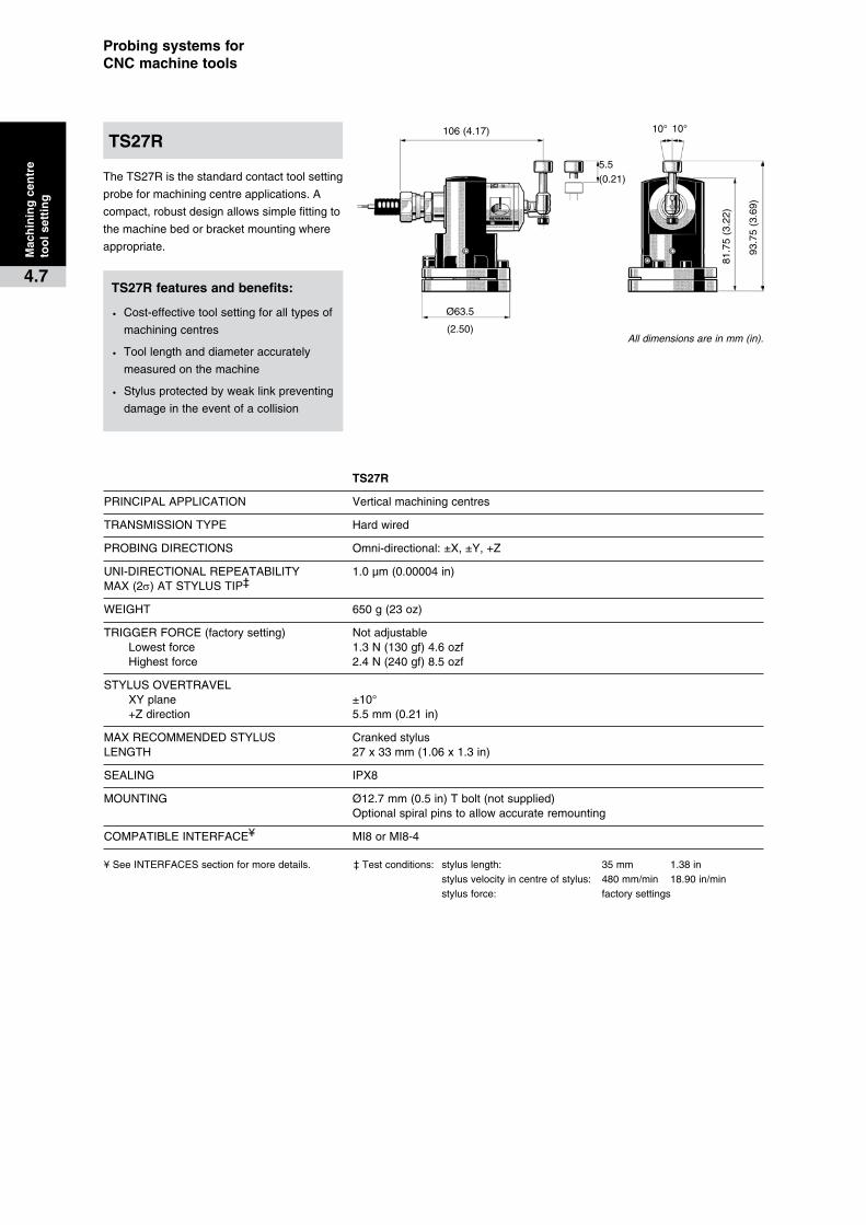
TheTS27Risthestandardcontacttoolsetting
probeformachiningcentreapplications.A
compact,robustdesignallowssimplefittingto
themachinebedorbracketmountingwhere
appropriate.
� � TS27R
PRINCIPALAPPLICATION Verticalmachiningcentres
TRANSMISSIONTYPE Hardwired
PROBINGDIRECTIONS Omni-directional:±X,±Y,+Z
UNI-DIRECTIONALREPEATABILITY 1.0µm(0.00004in)MAX(2s)ATSTYLUSTIP‡
WEIGHT 650g(23oz)
TRIGGERFORCE(factorysetting) Notadjustable Lowestforce 1.3N(130gf)4.6ozf Highestforce 2.4N(240gf)8.5ozf
STYLUSOVERTRAVEL XYplane ±10° +Zdirection 5.5mm(0.21in)
MAXRECOMMENDEDSTYLUS CrankedstylusLENGTH 27x33mm(1.06x1.3in)
SEALING IPX8
MOUNTING Ø12.7mm(0.5in)Tbolt(notsupplied) Optionalspiralpinstoallowaccurateremounting
COMPATIBLEINTERFACE¥ MI8orMI8-4
¥SeeINTERFACESsectionformoredetails. ‡Testconditions: styluslength: 35mm 1.38in stylusvelocityincentreofstylus: 480mm/min 18.90in/min stylusforce: factorysettings
All dimensions are in mm (in).
TS27R
Mac
hin
ing
�cen
tre
too
l�set
tin
g
4.7TS27R�features�and�benefits:
· Cost-effectivetoolsettingforalltypesof
machiningcentres
· Toollengthanddiameteraccurately
measuredonthemachine
· Stylusprotectedbyweaklinkpreventing
damageintheeventofacollision

Applications
Renishawprobescanbeusedonlathes
andgrindersforcomponentsettingand
inspectionapplications.
Component�setting
Theprobeidentifiesthepositionofthe
workpiece,automaticallyupdatingwork
offsets,enablingpartstobemanufactured
rightfirsttime.
Thiscanalsobeusedfor:
·��partidentificationforFMSinstallations.
·��componentlocationandalsomisload
detectiontoavoidscrap.
·� excessmaterialidentificationtobringthe
cuttertothecomponentfastandsafely.
First-off�inspection
Inspectionofthefirstcomponentinabatchon
themachinetoolto:
·��reducethetimethemachineisidleawaiting
feedbackfromanoff-lineinspectiondevice.
·� correctanyerrorsautomatically.
In-process�inspection
Measurecomponentsfollowingrough
machiningto:
·� ensurecriticalfinalcutsarecorrect.
·� highlighterrorsbeforetheybecomefaults.
Post-process�inspection
Inspectionofthepartoncethemachiningis
completed.Thiscanbeusedto:
·� provideinformationtocertifythatthe
componentiswithinitsspecification.
·� recordpartdimensionsforstatistical
processcontrol.
Probe�selection
Onlathes,inspectionprobesrequirearemote
transmissionsystem.Ongrinders,theprobe
istypicallyhard-wiredtotheCNC.
(seesection2,Transmissionselection).
Thenextpageshowssomeofthemost
commonlatheandgrinderinspectionprobe
applications:
1.Asmall,horizontallathefittedwithanLP2
probeusingthe�LTO2opticaltransmission.
2.Agrinderfittedwithahard-wiredLP2H
probe,allowingtheuseoflongerstyli.
3.TheRMP60probehasbeendesignedfor
workpiecemeasurementandjobset-up
onmediumtolargehorizontal,verticaland
gantrymachiningcentres,5-axismachines,
twinspindlemachinesandverticalturret
lathes(VTL).
CNC�lathe�and�grinder�inspection�probing�systems
Lat
he�
and
�gri
nd
erin
spec
tio
n
5.1
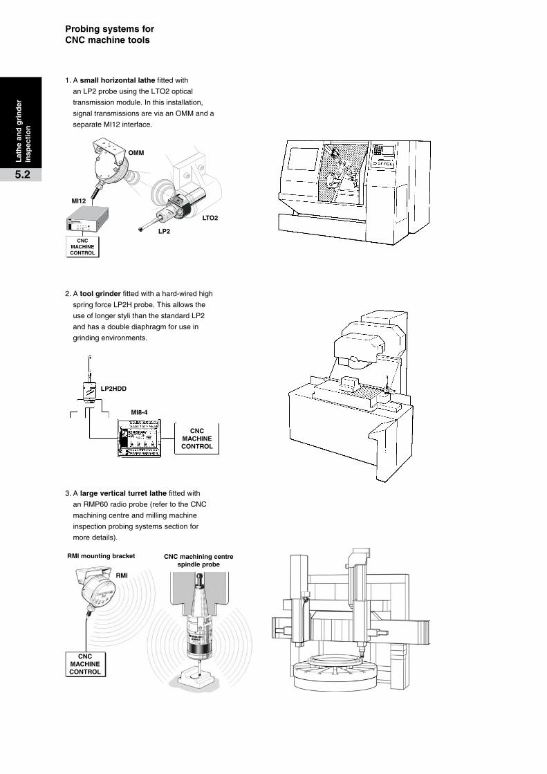
CNC�MACHINE�CONTROL
LTO2
LP2
OMM
MI12
CNC�MACHINE�CONTROL
MI8-4
LP2HDD
CNC�MACHINE�CONTROL
CNC�machining�centre�spindle�probe
RMI�mounting�bracket
RMI
Probing�systems�for��CNC�machine�tools
1.Asmall�horizontal�lathefittedwith
anLP2probeusingtheLTO2optical
transmissionmodule.Inthisinstallation,
signaltransmissionsareviaanOMManda
separateMI12interface.
3.Alarge�vertical�turret�lathefittedwith
anRMP60radioprobe(refertotheCNC
machiningcentreandmillingmachine
inspectionprobingsystemssectionfor
moredetails).
Lat
he�
and
�gri
nd
erin
spec
tio
n
5.2
2.Atool�grinderfittedwithahard-wiredhigh
springforceLP2Hprobe.Thisallowsthe
useoflongerstylithanthestandardLP2
andhasadoublediaphragmforusein
grindingenvironments.
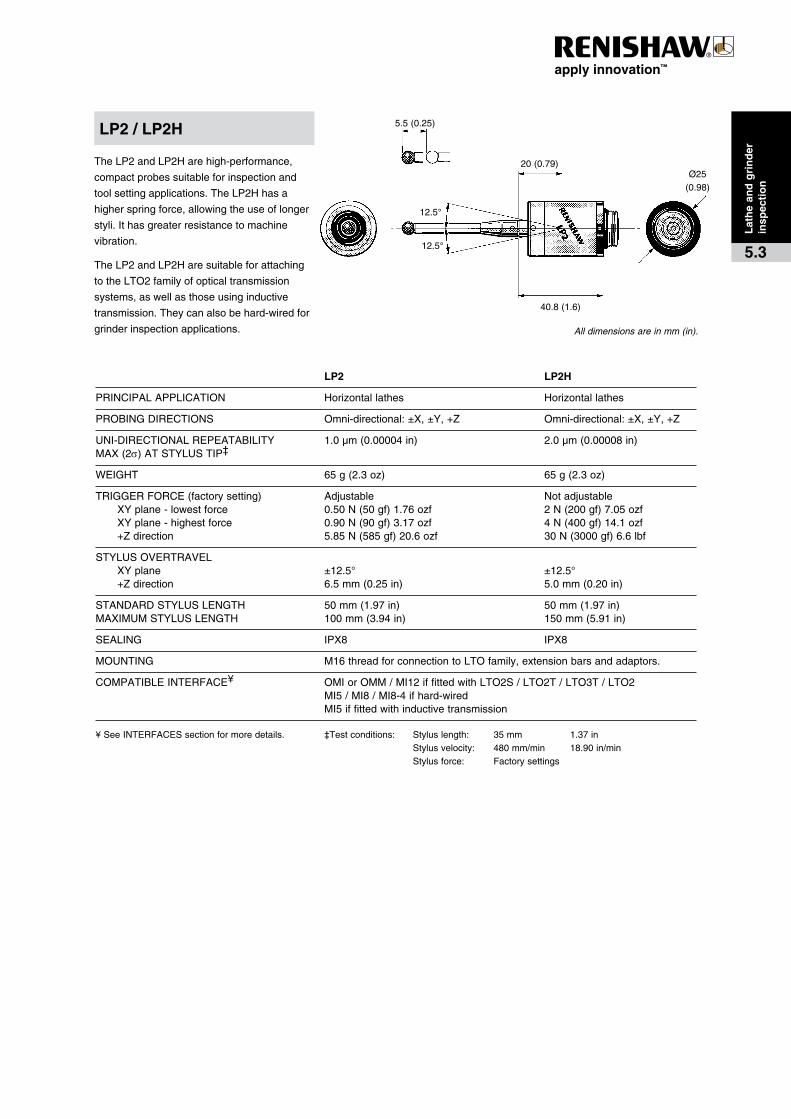
40.8(1.6)
12.5°
Ø25(0.98)
12.5°
20(0.79)
5.5(0.25)
� � LP2� � LP2H
PRINCIPALAPPLICATION Horizontallathes Horizontallathes
PROBINGDIRECTIONS Omni-directional:±X,±Y,+Z Omni-directional:±X,±Y,+Z
UNI-DIRECTIONALREPEATABILITY 1.0µm(0.00004in) 2.0µm(0.00008in)MAX(2s)ATSTYLUSTIP‡
WEIGHT 65g(2.3oz) 65g(2.3oz)
TRIGGERFORCE(factorysetting) Adjustable Notadjustable XYplane-lowestforce 0.50N(50gf)1.76ozf 2N(200gf)7.05ozf XYplane-highestforce 0.90N(90gf)3.17ozf 4N(400gf)14.1ozf +Zdirection 5.85N(585gf)20.6ozf 30N(3000gf)6.6lbf
STYLUSOVERTRAVEL XYplane ±12.5° ±12.5° +Zdirection 6.5mm(0.25in) 5.0mm(0.20in)
STANDARDSTYLUSLENGTH 50mm(1.97in) 50mm(1.97in)MAXIMUMSTYLUSLENGTH 100mm(3.94in) 150mm(5.91in)
SEALING IPX8 IPX8
MOUNTING M16threadforconnectiontoLTOfamily,extensionbarsandadaptors.
COMPATIBLEINTERFACE¥ OMIorOMM/MI12iffittedwithLTO2S/LTO2T/LTO3T/LTO2 MI5/MI8/MI8-4ifhard-wired MI5iffittedwithinductivetransmission
¥SeeINTERFACESsectionformoredetails. ‡Testconditions: Styluslength: 35mm 1.37in Stylusvelocity: 480mm/min 18.90in/min Stylusforce: Factorysettings
TheLP2andLP2Harehigh-performance,
compactprobessuitableforinspectionand
toolsettingapplications.TheLP2Hhasa
higherspringforce,allowingtheuseoflonger
styli.Ithasgreaterresistancetomachine
vibration.
TheLP2andLP2Haresuitableforattaching
totheLTO2familyofopticaltransmission
systems,aswellasthoseusinginductive
transmission.Theycanalsobehard-wiredfor
grinderinspectionapplications. All dimensions are in mm (in).
LP2�/�LP2H
Lat
he�
and
�gri
nd
erin
spec
tio
n
5.3
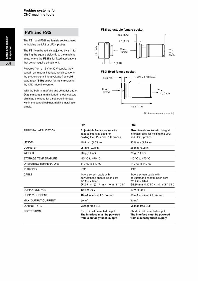
26(
1.02
)
45.5(1.79)
4.5(0.18)
M16x1thread
Cable
8(0.31)
Cable
45.5(1.79)
M16x1thread
4.5(0.18) M22x1-6Hthread
Probing�systems�for��CNC�machine�tools
TheFS1iandFS2iarefemalesockets,used
forholdingtheLP2orLP2Hprobes.
TheFS1icanberadiallyadjustedby±4°for
aligningthesquarestylustiptothemachine
axes,wheretheFS2iisforfixedapplications
thatdonotrequireadjustment.
Poweredfroma12Vto30Vsupply,they
containanintegralinterfacewhichconverts
theprobe’ssignalintoavoltage-freesolid
staterelay(SSR)outputfortransmissionto
theCNCmachinecontrol.
Withthebuilt-ininterfaceandcompactsizeof
Ø25mmx45.5mminlength,thesesockets
eliminatetheneedforaseparateinterface
withinthecontrolcabinet,makinginstallation
simple.
FS1i�and�FS2i
Lat
he�
and
�gri
nd
erin
spec
tio
n
5.4
FS1i�adjustable�female�socket
� FS1i�� FS2i
PRINCIPALAPPLICATION Adjustablefemalesocketwith Fixedfemalesocketwithintegral integralinterfaceusedfor interfaceusedforholdingtheLP2 holdingtheLP2andLP2Hprobes andLP2Hprobes
LENGTH 45.5mm(1.79in) 45.5mm(1.79in)
DIAMETER 25mm(0.98in) 25mm(0.98in)
WEIGHT 70g(2.4oz) 70g(2.4oz)
STORAGETEMPERATURE -10°Cto+70°C -10°Cto+70°C
OPERATINGTEMPERATURE +10°Cto+40°C +10°Cto+40°C
IPRATING IPX8 IPX8
CABLE 4-corescreencablewith 5-corescreencablewith polyurethanesheath.Eachcore polyurethanesheath.Eachcore 7/0.2insulated. 7/0.2insulated. Ø4.35mm(0.17in)×1.0m(3ft3in) Ø4.35mm(0.17in)×1.0m(3ft3in)
SUPPLYVOLTAGE 12Vto30V 12Vto30V
SUPPLYCURRENT 18mAnominal,25mAmax 18mAnominal,25mAmax.
MAX.OUTPUTCURRENT 50mA 50mA
OUTPUTTYPE Voltage-freeSSR Voltage-freeSSR
PROTECTION Shortcircuitprotectedoutput Shortcircuitprotectedoutput. The�interface�must�be�powered� The�interface�must�be�powered�� from�a�suitably�fused�supply.�� from�a�suitably�fused�supply�
FS2i�fixed�female�socket
All dimensions are in mm (in).

40.8(1.6)
Ø25(0.98)
LTO2T�/�3T
Ø62.0(2.44)
50.5(1.99)
61.9(2.44)LTO2T�80.0(3.14)LTO3T
40.8(1.6)
87.0(3.42)
Ø25(0.98)
LTO2S
Ø62.0(2.44)
LTO2
32(1.25)
40.8(1.6)
59.7(2.35)
Ø50.2(1.97)
Ø25(0.98)
LTO2S�/�LTO2T�/�LTO3T�/�LTO2��optical�transmissions
TheLTOfamilywithopticaltransmissionisidealforturret
mountingonallCNClathes.
AllLTOunitscanbefittedwithLP2orLP2Hprobes.
� � LTO2S� LTO2T� LTO3T� LTO2
TRANSMISSIONTYPE† Uni-directionalinfra-redopticaltransmission
PRINCIPALAPPLICATION Large/mediumlathes Mediumlathes Mediumlathes Smalllathes
TURNON/OFFMETHOD Opticalon/opticaloff Opticalon/opticaloff Opticalon/opticaloff Opticalon/timeroff oropticalon/timeroff oropticalon/timeroff oropticalon/timeroff
WEIGHT(includingprobe) 835g 625g 680g 355g
BATTERYTYPEANDLIFE 6LR61(PP39Valkaline)DL123A DL123A(2pieces) DL123A Standby 365days 108days 280days 65days 5%usage 80–98days 42–45days 110–114days 35days Continuouslife 110–140hours 81–88hours 183–225hours 88hours
SEALING IPX8 IPX8 IPX8 IPX8
SHANKS Various Ø25mm(0.98in) Ø25mm(0.98in) Ø25mm(0.98in) Ø25.4mm(1in) Ø25.4mm(1in)
COMPATIBLEINTERFACE¥ OMIorOMM/MI12 OMIorOMM/MI12 OMIorOMM/MI12 OMIorOMM/MI12
†SeeTRANSMISSIONSYSTEMSsectionformoredetails.¥SeeINTERFACESsectionformoredetails.
Inductive�transmissionInductivetransmissionisnotrecommendedforretrofitinstallations.MachinebuildersshouldcontacttheirRenishawsupplierforfurtherdetailsorvisitwebsitewww.renishaw.com.
Extensionbarsandadaptors
arealsoavailableforspecial
applications.
Lat
he�
and
�gri
nd
erin
spec
tio
n
5.5
All dimensions are in mm (in).
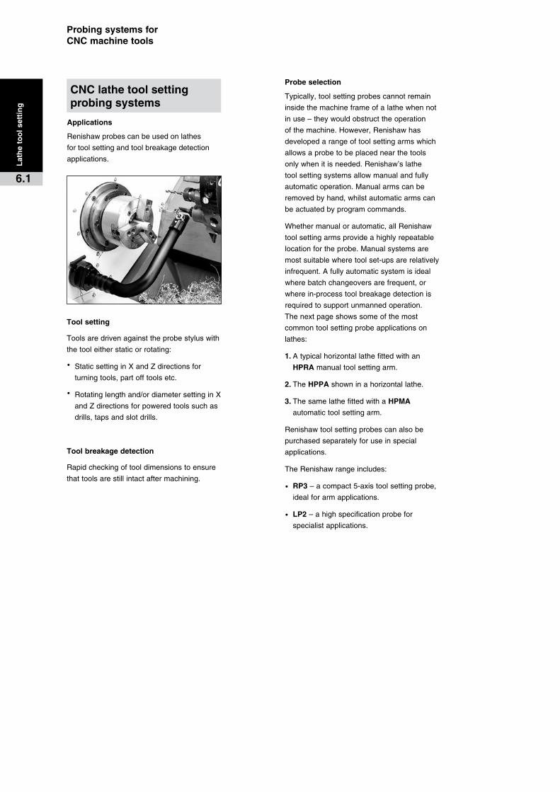
Probing�systems�for��CNC�machine�tools
Applications
Renishawprobescanbeusedonlathes
fortoolsettingandtoolbreakagedetection
applications.
Tool�setting
Toolsaredrivenagainsttheprobestyluswith
thetooleitherstaticorrotating:
·� StaticsettinginXandZdirectionsfor
turningtools,partofftoolsetc.
·� Rotatinglengthand/ordiametersettinginX
andZdirectionsforpoweredtoolssuchas
drills,tapsandslotdrills.
Tool�breakage�detection
Rapidcheckingoftooldimensionstoensure
thattoolsarestillintactaftermachining.
Probe�selection
Typically,toolsettingprobes�cannotremain
insidethemachineframeofalathewhennot
inuse–theywouldobstructtheoperation
ofthemachine.However,Renishawhas
developedarangeoftoolsettingarmswhich
allowsaprobetobeplacednearthetools
onlywhenitisneeded.Renishaw’slathe
toolsettingsystemsallowmanualandfully
automaticoperation.Manualarmscanbe
removedbyhand,whilstautomaticarmscan
beactuatedbyprogramcommands.
Whethermanualorautomatic,allRenishaw
toolsettingarmsprovideahighlyrepeatable
locationfortheprobe.Manualsystemsare
mostsuitablewheretoolset-upsarerelatively
infrequent.Afullyautomaticsystemisideal
wherebatchchangeoversarefrequent,or
wherein-processtoolbreakagedetectionis
requiredtosupportunmannedoperation.
Thenextpageshowssomeofthemost
commontoolsettingprobeapplicationson
lathes:
1.Atypicalhorizontallathefittedwithan
HPRAmanualtoolsettingarm.
2.TheHPPAshowninahorizontallathe.
3.ThesamelathefittedwithaHPMA
automatictoolsettingarm.
Renishawtoolsettingprobescanalsobe
purchasedseparatelyforuseinspecial
applications.
TheRenishawrangeincludes:
·� RP3–acompact5-axistoolsettingprobe,
idealforarmapplications.
·� LP2–ahighspecificationprobefor
specialistapplications.
Lat
he�
too
l�set
tin
g
6.1
CNC�lathe�tool�setting�probing�systems
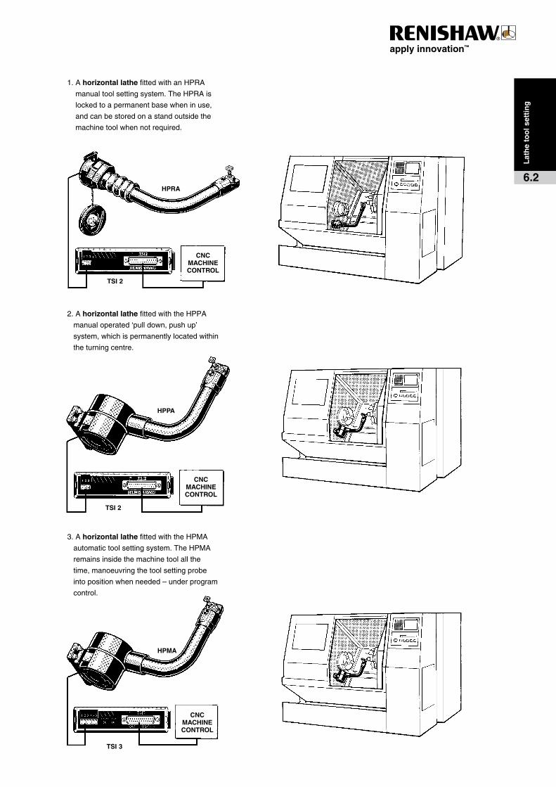
HPPA
TSI�2
CNC�MACHINE�CONTROL
HPMA
TSI�3
CNC�MACHINE�CONTROL
2.Ahorizontal�lathefittedwiththeHPPA
manualoperated‘pulldown,pushup’
system,whichispermanentlylocatedwithin
theturningcentre.
3.Ahorizontal�lathefittedwiththeHPMA
automatictoolsettingsystem.TheHPMA
remainsinsidethemachinetoolallthe
time,manoeuvringthetoolsettingprobe
intopositionwhenneeded–underprogram
control.
HPRA
CNC�MACHINE�CONTROL
TSI�2
1.Ahorizontal�lathefittedwithanHPRA
manualtoolsettingsystem.TheHPRAis
lockedtoapermanentbasewheninuse,
andcanbestoredonastandoutsidethe
machinetoolwhennotrequired.
Lat
he�
too
l�set
tin
g
6.2

S
A
B
Probing�systems�for��CNC�machine�tools
TheHPRAisa‘plug-in’armwhichismanually
locatedinsidethemachinefor
toolsetting,andthenremovedoncethe
processiscomplete.
Thearmislockedintoarepeatablekinematic
locationonamountingbaseduringoperation,
enablingtheprobestylustobere-locatedto
within5µm(2s).
WhennotinusetheHPRAisstoredona
standlocatedonornearthemachine.
�� � HPRA
PRINCIPALAPPLICATION Toolsettingon2-axisand3-axislathes
TYPICALPOSITIONALREPEATABILITY 5.0µm2s 0.0002in(Armsformachineswith6into15inchucks)MAX(2s)ATSTYLUSTIP‡ 8.0µm2s 0.0003in(Armsformachineswith18inand24inchucks)
ARMDIMENSIONS Maximum A 580mm(22.85in) B 450mm(17.73in) S(50mmtooling) 71mm(2.80in)
ARMDIMENSIONS Minimum A 250mm(9.84in) B 211mm(8.31in) S(16mmtooling) 35.7mm(1.41in)
BASEDIAMETER 85mm(3.35in)
SEALING IPX8
PROBE RP3
COMPATIBLEINTERFACE¥ TSI2
¥See INTERFACESsectionformoredetails. ‡Testconditions: styluslength: 22mm 0.87in stylusvelocity: 36mm/min 1.42in/min stylusforce: factorysettings
All dimensions are in mm (in).
Lat
he�
too
l�set
tin
g
6.3
HPRAHigh�precision�removable�arm

S
B
ATheHPPAisasimple,manuallyoperated
‘pull-down,push-up’system,whichis
permanentlylocatedwithintheturning
centreandreadilyavailablefortool
settingoperations.
Aninnovativepatentedrotarydevice
automaticallylocksthearmintoakinematic
location,withnoadditionaladjustmentor
lockingdevicerequired.Thisenablesthe
probe’sstylustobere-locatedtowithin
5µm(2s).
� � HPPA
PRINCIPALAPPLICATION Toolsettingon2-axisand3-axislathes
TYPICALPOSITIONALREPEATABILITY 5.0µm2sx/z 0.0002in(Armsformachineswith6into15inchucks)MAX(2s)ATSTYLUSTIP‡ 8.0µm2sx/z 0.0003in(Armsformachineswith18inand24inchucks)
ARMDIMENSIONS Maximum A 555mm(21.87in) B 458.2mm(18.04in) S(50mmtooling) 71mm(2.80in)
ARMDIMENSIONS Minimum A 250mm(9.84in) B 219.2mm(8.63in) S(16mmtooling) 35.7mm(1.41in)
SEALING IPX8(static)
PROBE RP3
COMPATIBLEINTERFACE¥ TSI2
¥SeeINTERFACESsectionformoredetails ‡Testconditions:styluslength: 22mm 0.87in stylusvelocity: 36mm/min 1.42in/min stylusforce: factorysettings
Lat
he�
too
l�set
tin
g
6.4
HPPAHigh�precision�pull-down�arm
All dimensions are in mm (in).

S
B
A
Probing�systems�for��CNC�machine�tools
TheHPMAisanelectricallypoweredarm
allowingprecisionautomatedtoolsetting.
Rapidactuationallowsin-processtoolsetting
andbrokentooldetectionwithouttheneedfor
operatorintervention.
Thearmswingsdownunderprogramcontrol
andlocksintopositionwithin2seconds.
Afterthetoolshavebeenset,aprogram
commandreturnsthearmtoasafeposition
awayfromthemachiningoperations.
Aninnovativepatentedrotarydevice
automaticallylocksthearmintoakinematic
location,withnoadditionaladjustmentor
lockingdevicerequired.
TheHPMAisavailableinarangeofstandard
armdimensions.Alternatively,customised
armscanbespecifiedwithinthedimension
limitsoutlinedbelow.
HPMA
PRINCIPALAPPLICATION Toolsettingandtoolbreakagedetectionon2-axisand3-axislathes
TYPICALPOSITIONAL 5.0µm2sx/z0.0002in(Armsformachineswith6into15inchucks)REPEATABILITY 8.0µm2sx/z0.0003in(Armsformachineswith18inand24inchucks)
ARMDIMENSIONS Maximum A 555mm(21.85in) B 458.2mm(18.04in) S(50mmtooling) 71mm(2.8in)
ARMDIMENSIONS Minimum A 250mm(9.84in) B 219.2mm(8.63in) S(50mmtooling) 35.7mm(1.4in)
SEALING IPX8(static)
PROBE RP3
COMPATIBLEINTERFACE¥ TSI3
¥SeeINTERFACESsectionformoredetails ‡Testconditions: styluslength: 22mm 0.87in stylusvelocity: 36mm/min 1.42in/min stylusforce: factorysettings
All dimensions are in mm (in).
Lat
he�
too
l�set
tin
g
6.5
HPMAHigh�precision�motorised�arm

9° 9°
2(0.08)
40.25(1.58)
Ø29.5(1.161)
TheRP3probehasbeendesignedprimarily
fortoolsettingapplicationsbutcanalsobe
usedinworkpiecesetup.
TheRP3probeissuitableforOEMinstallation
intopurposebuiltholders.Itutilisesa
universalM4stylusmounting,allowingthefull
rangeofRenishawstylitobeused.
WhenfittingtheRP3toanOEMtoolholder,
anOEMkitisavailablethatenableseasy
connectionfromtheprobeconnection
terminalstotheinterfacecable(forfurther
details,pleasecontactyourlocalRenishaw
office).
Theprobeisextremelyshort,resulting
insignificantadvantagesintoolsetting
applicationsandhastheperformanceof
traditionalRenishawtouchtriggerprobes.
Lat
he�
too
l�set
tin
g
6.6
RP3�probeFor�Renishaw�HP�tool�setting�arms
� � RP3
PRINCIPALAPPLICATION Manualandautomatictoolsettingarmson2-axisand 3-axislathes
TRANSMISSIONTYPE† Hard-wired
PROBEOUTPUTS OEMkitincludingconnectionPCB
PROBINGDIRECTIONS Omni-directional:±X,±Y,+Z
UNI-DIRECTIONALREPEATABILITY 1.0µm(0.00004in)MAX(2s)ATSTYLUSTIP‡
WEIGHT 80g(3oz)
TRIGGERFORCE(factorysetting) notadjustable Lowestforce 1.5N(150gf)5.3ozf Highestforce 3.5N(350gf)12.3ozf +Zdirection 12.0N(1200gf)42.3ozf
STYLUSOVERTRAVEL XYplane ±9° +Zdirection 2mm(0.8in)
MAXRECOMMENDEDSTYLUSLENGTH 48.25mm(1.90in)
SEALING IPX8
MOUNTING Refertotheuserguideforcustomerintegrationdetails
COMPATIBLEINTERFACE¥ MI8-4
†SeeTRANSMISSIONSYSTEMSsectionformoredetails. ‡Testconditions:styluslength: 35mm 1.38in¥SeeINTERFACESsectionformoredetails. stylusvelocity: 8mm/sec 0.31in/sec stylusforce: factorysettings
All dimensions are in mm (in).

131(5.15)
57(2.24)
160(6.3)
100(3.94)
196(7.71)
33(1.30)
MI12�and�MI12E�
MI12-B�
Probing�systems�for��CNC�machine�tools
TheMI12andMI12-Binterfacesprocess
signalsbetweenoneortwoOMMsandthe
CNCmachinecontrol.
ThestandardMI12unitiscontainedwithina
free-standingenclosurewithanoptionalpanel
mountingkitalsoavailable.TheMI12-Bisa
board-onlyversionformountingwithinthe
machinecabinet.
TheMI12Einterfaceformspartofthe
highpoweropticaltransmissionsystem.
Itprocessessignalsbetweenoneortwo
OMMEsandtheCNCmachine’scontrol.For
optimumsystemperformance,theMI12E
shouldonlybeusedwithOMME(s).
All dimensions are in mm (in).
� � MI12�/�MI12-B�/�MI12E
PRINCIPALAPPLICATION Opticaltransmissionprobingsystemsonmachiningcentresandlathes
MOUNTING Free-standingenclosure(optionalpanelmountavailable) TheMI12-Bhasself-adhesivefeetorM4supportstuds
SYSTEMSTATUS Audibleindicator ‘Bleeper’ ErrorLED Illuminatedwhenthebeamisobstructed,theprobeisoutof range,ortheprobeisoff LowbatteryLED Indicatesprobebatteriesshouldbereplaced ProbestatusLED Illuminatedwhentheprobeisseated.Offwhenthestylus isdeflected PowerLED Illuminatedwhenpowerison Startbutton Manual-startpush-buttononthefrontoftheinterface
MACHINESTARTOPTIONS 1.Machinestart OMM/OMMEsendsastartsignalwhencommandedby themachinecontrol 2.Autostart OMM/OMMEsendsastartsignalonceeverysecond whentheprobeisnottransmitting
OUTPUTS Foursolidstaterelay(SSR)outputs 1.Probestatus(orcomplement) 2.Probeskip(orcomplement) 3.Probeerror(orcomplement) 4.Lowbattery
OUTPUTSIGNALFORMAT Outputsignalsmustbecompatiblewiththemachinecontrolinput Maximumcurrent ±50mA Maximumvoltage ±50Vpeak
OTHERI/O Remoteaudibleindicatororlamp(notsuppliedbyRenishaw) Maximumcurrent 100mA Maximumvoltage +50Vdc Outputduration 44ms
POWERSUPPLY TheinterfacecandrawitssupplyfromtheCNC+15Vto+30Vdcandpresents aloadofupto400mA Alternatively,theRenishawPSU3powersupplyunitcanbeused
Inte
rfac
es
7.1
Machine�interface�units
MI12/MI12E/MI12-B�(Optical�transmission)

120(4.72)20
(0.78)
63(2.48)
131(5.16)
178(7.00)
49(1.93)
Inte
rfac
es
7.2
TheMI5interfaceprocessessignalsfromRenishawinductiveprobesandconvertsthesignalsintovoltage-freesolid-staterelay(SSR)output,fortransmissiontothemachine’scontroller.
TheMI8interfaceprocessessignalsfrom
Renishawhard-wiredprobesandconverts
thesignalsintoavoltage-freesolid-staterelay
(SSR)outputforconnectiontothemachine’s
controller.
� MI5
PRINCIPALAPPLICATION Inductiveprobingsystemsonmachiningcentresandlathes
MOUNTING Free-standingenclosure
SYSTEMSTATUS Audibleindicator ‘Bleeper’ ProbeStatusLED Onwhentheprobeisseated. Offwhenthestylusisdeflectedorpowerisoff
OUTPUT 1.ProbeStatus(orcomplement) 2.ProbeSkip(orcomplement)
OUTPUTSIGNALFORMAT Solidstaterelay(SSR)Maximumcurrent 40mApeakMaximumvoltage ±50Vpeak
POWERSUPPLY TheMI5candrawitssupplyfromtheCNC+18Vto+30Vdc TheMI5presentsaloadofupto200mA Alternatively,theRenishawPSU3powersupplyunitcanbeused
� � MI8
PRINCIPALAPPLICATION Hard-wiredprobingsystemsonmachiningcentresandlathes
MOUNTING Selfadhesivefeet,M4studdedsupportorDINrailmounting
SYSTEMSTATUS ProbestatusLED Onwhentheprobeisseated. Offwhenthestylusisdeflectedorpowerisoff
OUTPUT 1.ProbeStatus/StatusBar–configurable
OUTPUTSIGNALFORMAT Solidstaterelay(SSR) Maximumcurrent 50mApeak Maximumvoltage ±50Vpeak
OTHERI/O OutputsareavailableforaremoteprobestatusLED (notsuppliedbyRenishaw).Nominalcurrentis10mA
POWERSUPPLY TheMI8candrawitssupplyfromtheCNC+15Vto+30Vdc TheMI8presentsaloadofupto50mA Alternatively,theRenishawPSU3powersupplyunitcanbeused
All dimensions are in mm (in).
MI5�(Inductive�transmission)
MI8�(Hard-wired�transmission)
All dimensions are in mm (in).
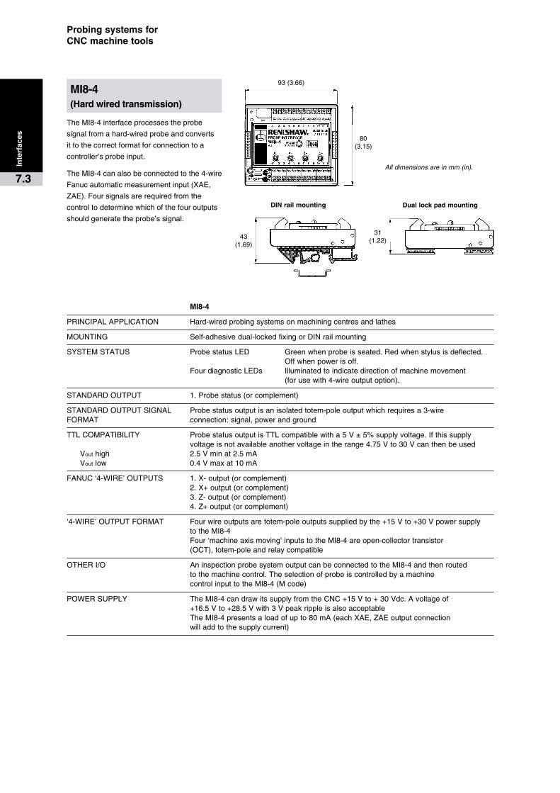
93(3.66)
43(1.69)
31(1.22)
DIN�rail�mounting Dual�lock�pad�mounting
80(3.15)
Probing�systems�for��CNC�machine�tools
TheMI8-4interfaceprocessestheprobe
signalfromahard-wiredprobeandconverts
ittothecorrectformatforconnectiontoa
controller’sprobeinput.
TheMI8-4canalsobeconnectedtothe4-wire
Fanucautomaticmeasurementinput(XAE,
ZAE).Foursignalsarerequiredfromthe
controltodeterminewhichofthefouroutputs
shouldgeneratetheprobe’ssignal.
MI8-4
PRINCIPALAPPLICATION Hard-wiredprobingsystemsonmachiningcentresandlathes
MOUNTING Self-adhesivedual-lockedfixingorDINrailmounting
SYSTEMSTATUS ProbestatusLED Greenwhenprobeisseated.Redwhenstylusisdeflected. Offwhenpowerisoff. FourdiagnosticLEDs Illuminatedtoindicatedirectionofmachinemovement (forusewith4-wireoutputoption).
STANDARDOUTPUT 1.Probestatus(orcomplement)
STANDARDOUTPUTSIGNAL Probestatusoutputisanisolatedtotem-poleoutputwhichrequiresa3-wireFORMAT connection:signal,powerandground
TTLCOMPATIBILITY ProbestatusoutputisTTLcompatiblewitha5V±5%supplyvoltage.Ifthissupply voltageisnotavailableanothervoltageintherange4.75Vto30Vcanthenbeused Vouthigh 2.5Vminat2.5mA Voutlow 0.4Vmaxat10mA
FANUC‘4-WIRE’OUTPUTS 1.X-output(orcomplement) 2.X+output(orcomplement) 3.Z-output(orcomplement) 4.Z+output(orcomplement)
‘4-WIRE’OUTPUTFORMAT Fourwireoutputsaretotem-poleoutputssuppliedbythe+15Vto+30Vpowersupply totheMI8-4 Four‘machineaxismoving’inputstotheMI8-4areopen-collectortransistor (OCT),totem-poleandrelaycompatible
OTHERI/O AninspectionprobesystemoutputcanbeconnectedtotheMI8-4andthenrouted tothemachinecontrol.Theselectionofprobeiscontrolledbyamachine controlinputtotheMI8-4(Mcode)
POWERSUPPLY TheMI8-4candrawitssupplyfromtheCNC+15Vto+30Vdc.Avoltageof +16.5Vto+28.5Vwith3Vpeakrippleisalsoacceptable TheMI8-4presentsaloadofupto80mA(eachXAE,ZAEoutputconnection willaddtothesupplycurrent)
Inte
rfac
es
7.3
MI8-4�(Hard�wired�transmission)
All dimensions are in mm (in).
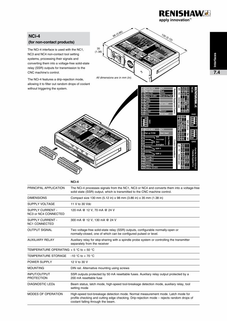
98(3.86)
35(1.38)
130(5.12)
Inte
rfac
es
7.4
TheNCi-4interfaceisusedwiththeNC1,
NC3andNC4non-contacttoolsetting
systems,processingtheirsignalsand
convertingthemintoavoltage-freesolid-state
relay(SSR)outputsfortransmissiontothe
CNCmachine’scontrol.
TheNCi-4featuresadrip-rejectionmode,
allowingittofilteroutrandomdropsofcoolant
withouttriggeringthesystem.
NCi-4�(for�non-contact�products)
� NCi-4
PRINCIPALAPPLICATION TheNCi-4processessignalsfromtheNC1,NC3orNC4andconvertsthemintoavoltage-freesolidstate(SSR)output,whichistransmittedtotheCNCmachinecontrol.
DIMENSIONS Compactsize130mm(5.12in)x98mm(3.86in)x35mm(1.38in)
SUPPLYVOLTAGE 11Vto30Vdc
SUPPLYCURRENT- 120mA@12V,70mA@24VNC3orNC4CONNECTED
SUPPLYCURRENT- 300mA@12V,130mA@24VNC1CONNECTED
OUTPUTSIGNAL Twovoltage-freesolid-staterelay(SSR)outputs,configurablenormally-openor normally-closed,oneofwhichcanbeconfiguredpulsedorlevel.
AUXILIARYRELAY Auxiliaryrelayforskip-sharingwithaspindleprobesystemorcontrollingthetransmitter separatelyfromthereceiver
TEMPERATUREOPERATING +5°Cto+50°C
TEMPERATURESTORAGE -10°Cto+70°C
POWERSUPPLY 12Vto30V
MOUNTING DINrail.Alternativemountingusingscrews
INPUT/OUTPUT SSRoutputsprotectedby50mAresettablefuses.AuxiliaryrelayoutputprotectedbyaPROTECTION 200mAresettablefuse
DIAGNOSTICLEDs Beamstatus,latchmode,high-speedtool-breakagedetectionmode,auxiliaryrelay,tool settingmode
MODESOFOPERATION High-speedtool-breakagedetectionmode.Normalmeasurementmode.Latchmodefor profilecheckingandcuttingedgechecking.Drip-rejectionmode–rejectsrandomdropsof coolantfallingthroughthebeam.
All dimensions are in mm (in).
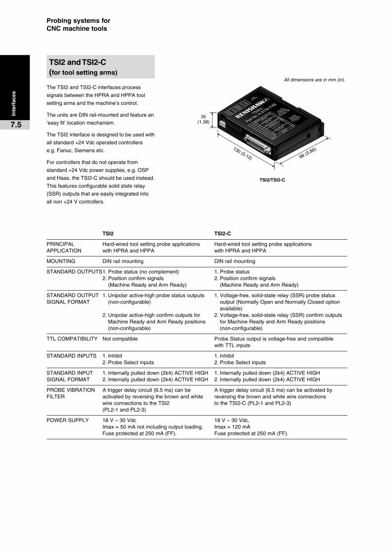
98(3.86)130(5.12)
35(1.38)
TSI2/TSI2-C
Probing�systems�for��CNC�machine�tools
TheTSI2andTSI2-Cinterfacesprocess
signalsbetweentheHPRAandHPPAtool
settingarmsandthemachine’scontrol.
TheunitsareDINrail-mountedandfeaturean
‘easyfit’locationmechanism.
TheTSI2interfaceisdesignedtobeusedwith
allstandard+24Vdcoperatedcontrollers
e.g.Fanuc,Siemensetc.
Forcontrollersthatdonotoperatefrom
standard+24Vdcpowersupplies,e.g.OSP
andHaas,theTSI2-Cshouldbeusedinstead.
Thisfeaturesconfigurablesolidstaterelay
(SSR)outputsthatareeasilyintegratedinto
allnon+24Vcontrollers.
TSI2�� TSI2-C
PRINCIPAL Hard-wiredtoolsettingprobeapplications Hard-wiredtoolsettingprobeapplicationsAPPLICATION withHPRAandHPPA withHPRAandHPPA
MOUNTING DINrailmounting DINrailmounting
STANDARDOUTPUTS1.Probestatus(nocomplement) 1.Probestatus 2.Positionconfirmsignals 2.Positionconfirmsignals (MachineReadyandArmReady) (MachineReadyandArmReady)
STANDARDOUTPUT1.Unipolaractive-highprobestatusoutputs 1.Voltage-free,solid-staterelay(SSR)probestatusSIGNALFORMAT (non-configurable) output(NormallyOpenandNormallyClosedoption available) 2.Unipolaractive-highconfirmoutputsfor 2.Voltage-free,solid-staterelay(SSR)confirmoutputs MachineReadyandArmReadypositions forMachineReadyandArmReadypositions (non-configurable) (non-configurable)
TTLCOMPATIBILITY Notcompatible ProbeStatusoutputisvoltage-freeandcompatible withTTLinputs
STANDARDINPUTS 1.Inhibit 1.Inhibit 2.ProbeSelectinputs 2.ProbeSelectinputs
STANDARDINPUT 1.Internallypulleddown(2k4)ACTIVEHIGH 1.Internallypulleddown(2k4)ACTIVEHIGHSIGNALFORMAT 2.Internallypulleddown(2k4)ACTIVEHIGH 2.Internallypulleddown(2k4)ACTIVEHIGH
PROBEVIBRATION Atriggerdelaycircuit(6.5ms)canbe Atriggerdelaycircuit(6.5ms)canbeactivatedbyFILTER activatedbyreversingthebrownandwhite reversingthebrownandwhitewireconnections wireconnectionstotheTSI2 totheTSI2-C(PL2-1andPL2-3) (PL2-1andPL2-3)
POWERSUPPLY 18V–30Vdc 18V–30Vdc, Imax=50mAnotincludingoutputloading. Imax=120mA Fuseprotectedat250mA(FF). Fuseprotectedat250mA(FF).
Inte
rfac
es
7.5
TSI2�and�TSI2-C��(for�tool�setting�arms)
All dimensions are in mm (in).
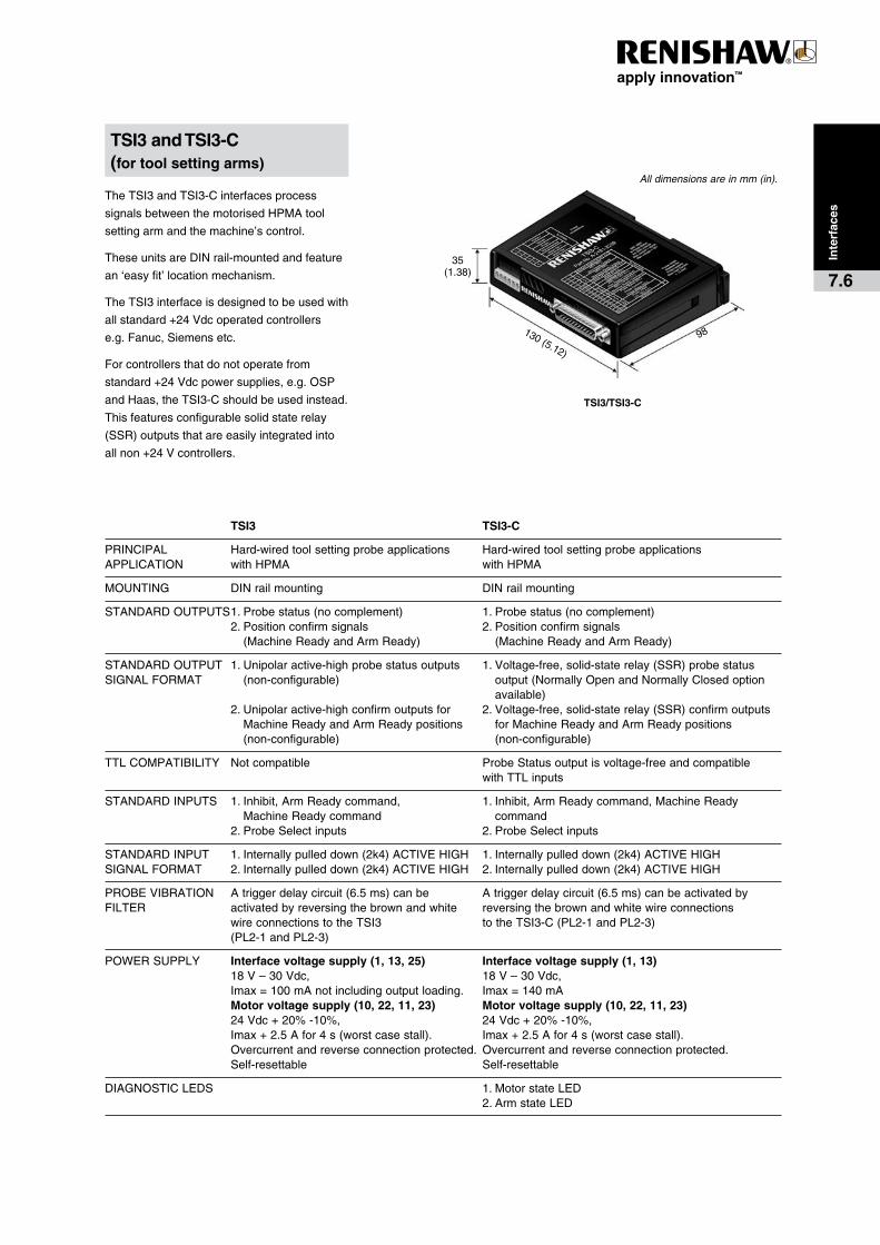
98130(5.12)
35(1.38)
TSI3/TSI3-C
Inte
rfac
es
7.6
TheTSI3andTSI3-Cinterfacesprocess
signalsbetweenthemotorisedHPMAtool
settingarmandthemachine’scontrol.
TheseunitsareDINrail-mountedandfeature
an‘easyfit’locationmechanism.
TheTSI3interfaceisdesignedtobeusedwith
allstandard+24Vdcoperatedcontrollers
e.g.Fanuc,Siemensetc.
Forcontrollersthatdonotoperatefrom
standard+24Vdcpowersupplies,e.g.OSP
andHaas,theTSI3-Cshouldbeusedinstead.
Thisfeaturesconfigurablesolidstaterelay
(SSR)outputsthatareeasilyintegratedinto
allnon+24Vcontrollers.
TSI3�� TSI3-C
PRINCIPAL Hard-wiredtoolsettingprobeapplications Hard-wiredtoolsettingprobeapplicationsAPPLICATION withHPMA withHPMA
MOUNTING DINrailmounting DINrailmounting
STANDARDOUTPUTS1.Probestatus(nocomplement) 1.Probestatus(nocomplement) 2.Positionconfirmsignals 2.Positionconfirmsignals (MachineReadyandArmReady) (MachineReadyandArmReady)
STANDARDOUTPUT1.Unipolaractive-highprobestatusoutputs 1.Voltage-free,solid-staterelay(SSR)probestatusSIGNALFORMAT (non-configurable) output(NormallyOpenandNormallyClosedoption available) 2.Unipolaractive-highconfirmoutputsfor 2.Voltage-free,solid-staterelay(SSR)confirmoutputs MachineReadyandArmReadypositions forMachineReadyandArmReadypositions (non-configurable) (non-configurable)
TTLCOMPATIBILITY Notcompatible ProbeStatusoutputisvoltage-freeandcompatible withTTLinputs
STANDARDINPUTS 1.Inhibit,ArmReadycommand, 1.Inhibit,ArmReadycommand,MachineReady MachineReadycommand command 2.ProbeSelectinputs 2.ProbeSelectinputs
STANDARDINPUT 1.Internallypulleddown(2k4)ACTIVEHIGH 1.Internallypulleddown(2k4)ACTIVEHIGHSIGNALFORMAT 2.Internallypulleddown(2k4)ACTIVEHIGH 2.Internallypulleddown(2k4)ACTIVEHIGH
PROBEVIBRATION Atriggerdelaycircuit(6.5ms)canbe Atriggerdelaycircuit(6.5ms)canbeactivatedbyFILTER activatedbyreversingthebrownandwhite reversingthebrownandwhitewireconnections wireconnectionstotheTSI3 totheTSI3-C(PL2-1andPL2-3) (PL2-1andPL2-3)
POWERSUPPLY Interface�voltage�supply�(1,�13,�25)� Interface�voltage�supply�(1,�13) 18V–30Vdc, 18V–30Vdc, Imax=100mAnotincludingoutputloading. Imax=140mA Motor�voltage�supply�(10,�22,�11,�23)� Motor�voltage�supply�(10,�22,�11,�23) 24Vdc+20%-10%, 24Vdc+20%-10%, Imax+2.5Afor4s(worstcasestall). Imax+2.5Afor4s(worstcasestall). Overcurrentandreverseconnectionprotected. Overcurrentandreverseconnectionprotected. Self-resettable Self-resettable
DIAGNOSTICLEDS 1.MotorstateLED 2.ArmstateLED
TSI3�and�TSI3-C��(for�tool�setting�arms)
All dimensions are in mm (in).
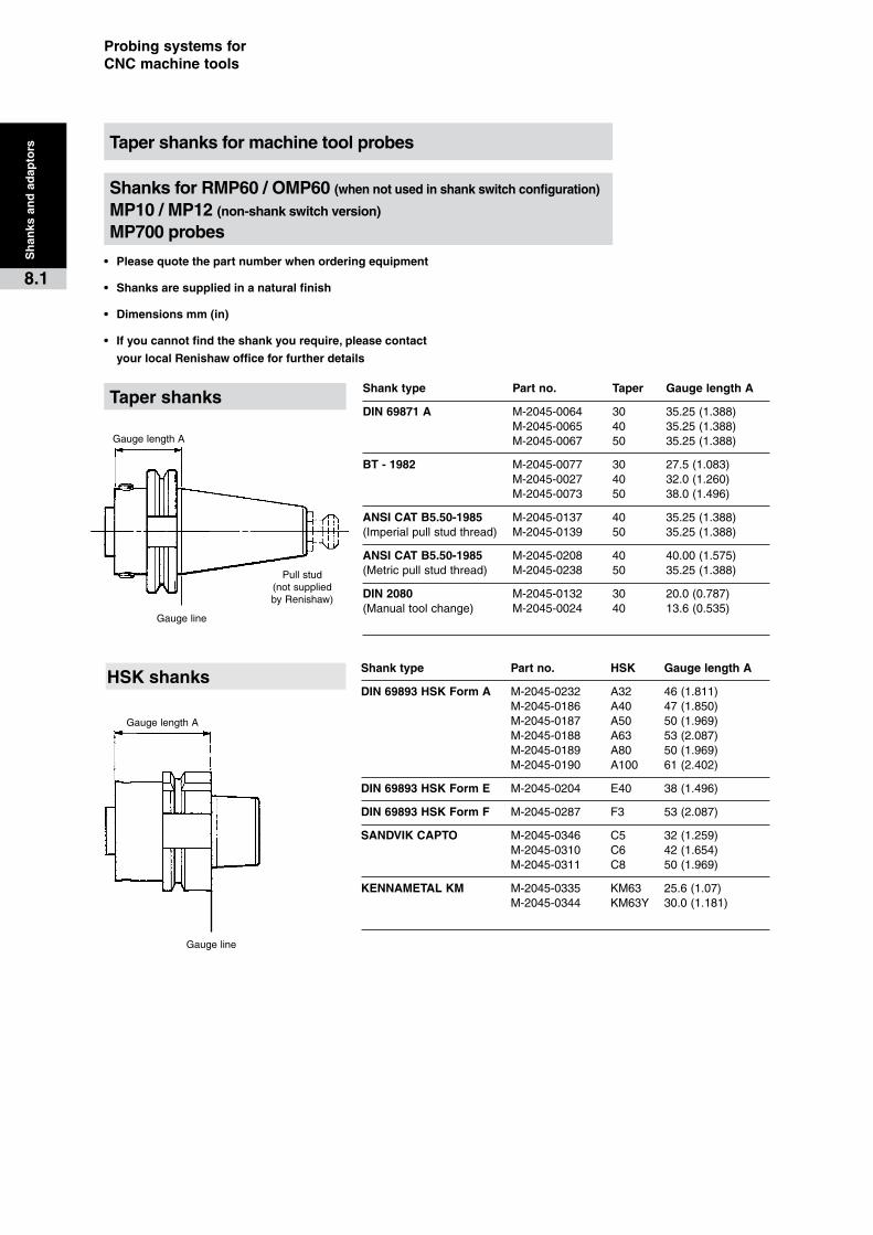
GaugelengthA
Gaugeline
Pullstud(notsuppliedbyRenishaw)
GaugelengthA
Gaugeline
Probing�systems�for��CNC�machine�tools
•� Please�quote�the�part�number�when�ordering�equipment
•� Shanks�are�supplied�in�a�natural�finish
•� Dimensions�mm�(in)
•� If�you�cannot�find�the�shank�you�require,�please�contact�
your�local�Renishaw�office�for�further�details
Sh
anks
�an
d�a
dap
tors
8.1
Taper�shanks�for�machine�tool�probes
Shanks�for�RMP60�/�OMP60�(when�not�used�in�shank�switch�configuration)��
MP10�/�MP12�(non-shank�switch�version)��
MP700�probes
Shank�type� Part�no.� HSK� Gauge�length�A
DIN�69893�HSK�Form�A M-2045-0232 A32 46(1.811) M-2045-0186 A40 47(1.850) M-2045-0187 A50 50(1.969) M-2045-0188 A63 53(2.087) M-2045-0189 A80 50(1.969) M-2045-0190 A100 61(2.402)
DIN�69893�HSK�Form�E M-2045-0204 E40 38(1.496)
DIN�69893�HSK�Form�F M-2045-0287 F3 53(2.087)
SANDVIK�CAPTO M-2045-0346 C5 32(1.259) M-2045-0310 C6 42(1.654) M-2045-0311 C8 50(1.969)
KENNAMETAL�KM M-2045-0335 KM63 25.6(1.07) M-2045-0344 KM63Y 30.0(1.181)
HSK�shanks
Shank�type� Part�no.� Taper� Gauge�length�A
DIN�69871�A M-2045-0064 30 35.25(1.388) M-2045-0065 40 35.25(1.388) M-2045-0067 50 35.25(1.388)
BT�-�1982 M-2045-0077 30 27.5(1.083) M-2045-0027 40 32.0(1.260) M-2045-0073 50 38.0(1.496)
ANSI�CAT�B5.50-1985 M-2045-0137 40 35.25(1.388)(Imperialpullstudthread) M-2045-0139 50 35.25(1.388)
ANSI�CAT�B5.50-1985 M-2045-0208 40 40.00(1.575)(Metricpullstudthread) M-2045-0238 50 35.25(1.388)
DIN�2080 M-2045-0132 30 20.0(0.787)(Manualtoolchange) M-2045-0024 40 13.6(0.535)
Taper�shanks

Shankswitch
Pullstud(notsuppliedbyRenishaw)
Bobbin
GaugelengthA
Gaugeline
Gaugeline
GaugelengthA
Shankswitch
Bobbin
Sh
anks
�an
d�a
dap
tors
8.2
Shanks�for�RMP60/OMP60�probes�when�used�in�shank�switch�configuration
•� Please�quote�the�part�number�when�ordering�equipment
•� Shanks�are�supplied�in�a�natural�finish
•� Bobbin�supplied�with�shank
•� Dimensions�mm�(in)
•� If�you�cannot�find�the�shank�you�require,�please�contact�
your�local�Renishaw�office�for�further�details
Shank�type� Part�no.� Taper� Gauge�length�A
DIN�69871�A M-4038-0231 30 65.00(2.559) M-4038-0053 40 35.25(1.388) M-4038-0232 50 41.00(1.614)
BT�-�1982 M-4038-0233 30 65.00(2.559) M-4038-0234 40 35.25(1.388) M-4038-0235 50 41.00(1.614)
ANSI�CAT�B5.50-1985 M-4038-0236 30 65.00(2.559)(Imperialpullstudthread) M-4038-0237 40 35.25(1.388) M-4038-0238 50 35.25(1.388)
ANSI�CAT�B5.50-1985 M-4038-0239 40 35.25(1.388)(Metricpullstudthread) M-4038-0240 50 35.25(1.388)
Shank�type� Part�no.� HSK� Gauge�length�A
DIN�69893�HSK�Form�A A-4038-0070 A40 65.00(2.559) A-4038-0050 A50 62.00(2.441) A-4038-0063 A63 50.00(1.969) A-4038-0241 A80 42.50(1.673) A-4038-0242 A100 45.50(1.791)
DIN�69893�HSK�Form�E M-4038-0243 E40 65.00(2.559) M-4038-0244 E50 62.00(2.441) M-4038-0245 E63 50.00(1.969)
Taper�shanks�
HSK�shanks�
Bobbin�for�shank�switch�configuration
Part�no.�
A-4038-0303
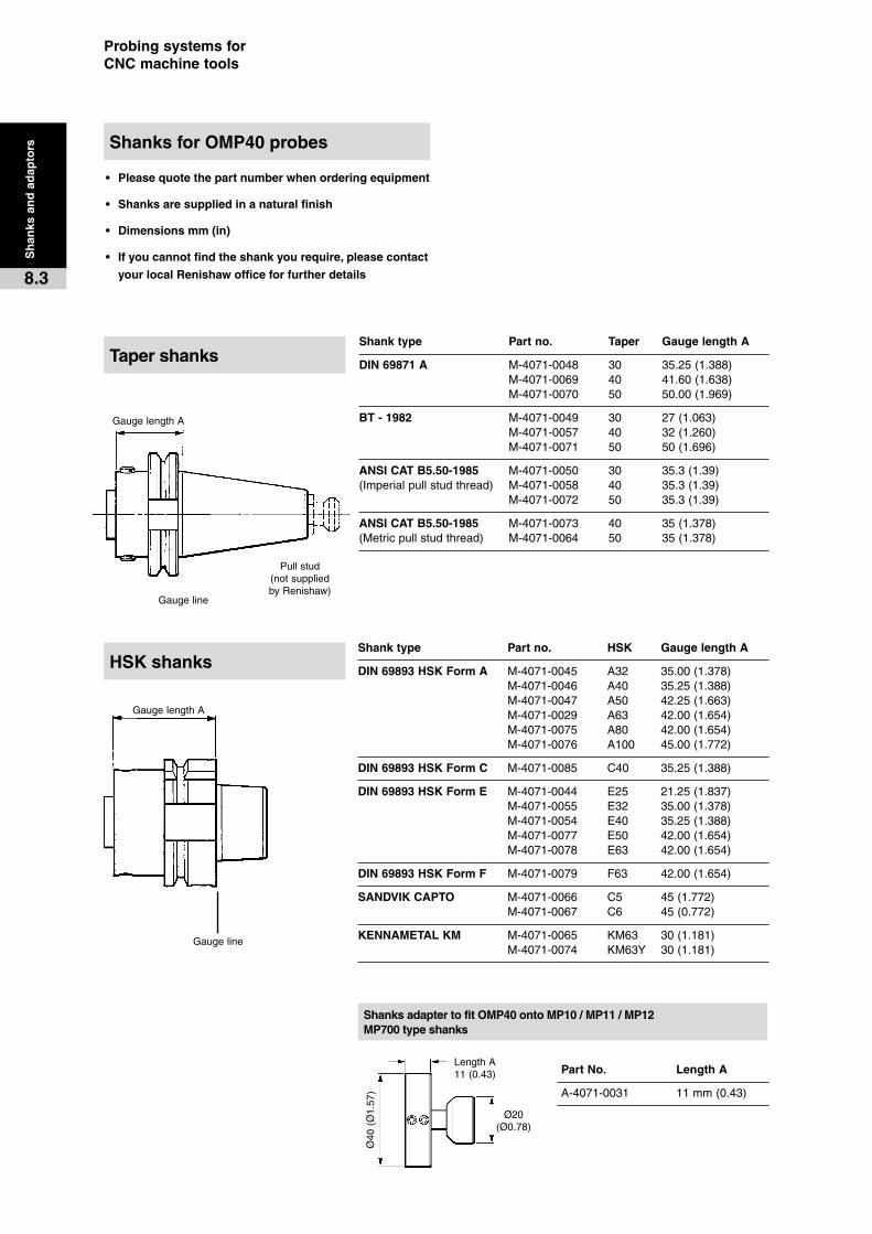
GaugelengthA
Gaugeline
Pullstud(notsuppliedbyRenishaw)
GaugelengthA
Gaugeline
LengthA11(0.43)
Ø40
(Ø
1.57
)
Ø20(Ø0.78)
Probing�systems�for��CNC�machine�tools
Shanks�for�OMP40�probes
Sh
anks
�an
d�a
dap
tors
8.3
Taper�shanks
HSK�shanks
Shank�type� Part�no.� Taper� Gauge�length�A
DIN�69871�A M-4071-0048 30 35.25(1.388) M-4071-0069 40 41.60(1.638) M-4071-0070 50 50.00(1.969)
BT�-�1982 M-4071-0049 30 27(1.063) M-4071-0057 40 32(1.260) M-4071-0071 50 50(1.696)
ANSI�CAT�B5.50-1985 M-4071-0050 30 35.3(1.39)(Imperialpullstudthread) M-4071-0058 40 35.3(1.39) M-4071-0072 50 35.3(1.39)
ANSI�CAT�B5.50-1985 M-4071-0073 40 35(1.378)(Metricpullstudthread) M-4071-0064 50 35(1.378)
Shank�type� Part�no.� HSK� Gauge�length�A
DIN�69893�HSK�Form�A M-4071-0045 A32 35.00(1.378) M-4071-0046 A40 35.25(1.388) M-4071-0047 A50 42.25(1.663) M-4071-0029 A63 42.00(1.654) M-4071-0075 A80 42.00(1.654) M-4071-0076 A100 45.00(1.772)
DIN�69893�HSK�Form�C M-4071-0085 C40 35.25(1.388)
DIN�69893�HSK�Form�E M-4071-0044 E25 21.25(1.837) M-4071-0055 E32 35.00(1.378) M-4071-0054 E40 35.25(1.388) M-4071-0077 E50 42.00(1.654) M-4071-0078 E63 42.00(1.654)
DIN�69893�HSK�Form�F M-4071-0079 F63 42.00(1.654)
SANDVIK�CAPTO M-4071-0066 C5 45(1.772) M-4071-0067 C6 45(0.772)
KENNAMETAL�KM M-4071-0065 KM63 30(1.181) M-4071-0074 KM63Y 30(1.181)
�Part�No.�� Length�A
A-4071-0031 11mm(0.43)
Shanks�adapter�to�fit�OMP40�onto�MP10�/�MP11�/�MP12��MP700�type�shanks
•� Please�quote�the�part�number�when�ordering�equipment
•� Shanks�are�supplied�in�a�natural�finish
•� Dimensions�mm�(in)
•� If�you�cannot�find�the�shank�you�require,�please�contact�
your�local�Renishaw�office�for�further�details

Stylus�extensions
Stylusextensionsgivegreater
reachandallowaccesstodeep
featureswithoutriskof
damagetotheprobe.
Crash�protection
Renishaw’sstyluscrash
protectiondevicesare
designedtobreak,
andprotecttheprobe
fromdamage.
Stylus�crank
Acrankcanallowaccess
tofeaturesthat
areotherwisedifficulttoreach,
andareoftenusedinlathe
inspectionapplications.
Stylus�selection�tips
Yourchoiceofstyluscanhaveanimpacton
measurementresults.Astylusshouldbeasstiffas
possible,soconsiderthefollowingpoints:
1.�Use�the�shortest�stylusthatallowsaccesstoall
thefeaturesthatyouwanttoprobe.
2.�Use�the�largest�ball�diameterthatallowsthe
stylustoenterthesmallestinternalfeatures.
Thiskeepsthestemdiameteraslargeas
possible.
3.�Minimise�the�number�of�joints�inthe
stylusassembly.
Regularstylusdatumingwillensurethatyou
achievethebestmeasurementaccuracy.
Accuracy�at�the�point��of�contact
Stylus��accessories
Sty
li�an
d�a
cces
sori
es
9.1
Asindustryhasdevelopeditsrequirement
forincreasinglydiverseandcomplex
manufacturedparts,inspectionsystems
havehadtoworkhardtokeepup.Theuseof
CMMswithprobingsystemsandin-process
inspectiononmachinetoolsaretwoofthe
solutionsofferedbyRenishawtohelpyou
maximiseyourproductivityandmaintainthe
highestpossiblestandardsofquality.
Successfulgaugingdependsverymuchon
theabilityoftheprobe'sstylustoaccess
afeatureandthenmaintainaccuracyat
thepointofcontact.Renishawhasused
itsexpertiseinprobeandstylusdesignto
developacomprehensiverangeofCMMand
machinetoolstylitoofferyouthegreatest
possibleprecision.
Pleaserefertothestyliandaccessories
technicalspecification(documentH-1000-
3200)formoredetails.
Stylus�types
Renishaw’sstylusrangecoversseveral
differenttypesfordifferentapplications:
Ruby�ball�styli
Thisisthestandardstylus
formostinspection
applications.Ahard,highlysphericaltip
ensureslonglifewithexcellentaccuracy.
Rubyballsareavailablemountedtostems
madefromavarietyofmaterialsincluding
non-magneticstainlesssteel,ceramicanda
specialisedcarbonfibrematerial,Renishaw
GF.
Disc�styli
These‘thinsections’ofa
largesphereareused
toprobeundercuts
andgrooves.
Asimplediscrequiresdatumingononly
onediameter(usuallyaringgauge),but
limitseffectiveprobingtoonlytheXandY
directions.
Tool�setting�styli
Typicallyfittedwitha
squaretip,toolsetting
stylicanhavethreadedor
plainshaftattachments.
Thestylustipfacesaregroundtoensurehigh
squarenessandparallelism.
NotethattheTS27Rtoolsettingprobefor
machiningcentrescanalsobefittedwitha
tungstencarbidediscstylus.
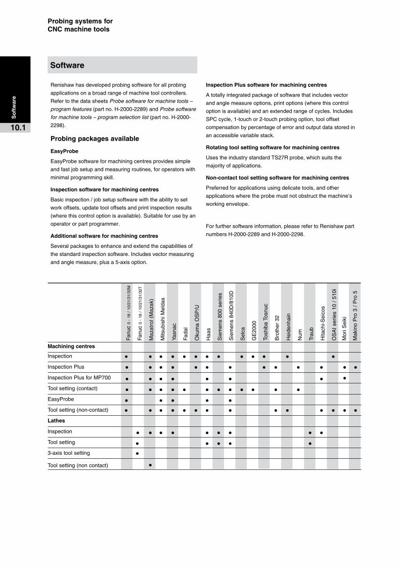
Probing�systems�for��CNC�machine�tools
Software
So
ftw
are
10.1
Renishawhasdevelopedprobingsoftwareforallprobing
applicationsonabroadrangeofmachinetoolcontrollers.
RefertothedatasheetsProbe software for machine tools –
program features(partno.H-2000-2289)andProbe software
for machine tools – program selection list(partno.H-2000-
2298).
Probing�packages�available
EasyProbe
EasyProbesoftwareformachiningcentresprovidessimple
andfastjobsetupandmeasuringroutines,foroperatorswith
minimalprogrammingskill.
Inspection�software�for�machining�centres
Basicinspection/jobsetupsoftwarewiththeabilitytoset
workoffsets,updatetooloffsetsandprintinspectionresults
(wherethiscontroloptionisavailable).Suitableforusebyan
operatororpartprogrammer.
Additional�software�for�machining�centres
Severalpackagestoenhanceandextendthecapabilitiesof
thestandardinspectionsoftware.Includesvectormeasuring
andanglemeasure,plusa5-axisoption.
Inspection�Plus�software�for�machining�centres
Atotallyintegratedpackageofsoftwarethatincludesvector
andanglemeasureoptions,printoptions(wherethiscontrol
optionisavailable)andanextendedrangeofcycles.Includes
SPCcycle,1-touchor2-touchprobingoption,tooloffset
compensationbypercentageoferrorandoutputdatastoredin
anaccessiblevariablestack.
Rotating�tool�setting�software�for�machining�centres
UsestheindustrystandardTS27Rprobe,whichsuitsthe
majorityofapplications.
Non-contact�tool�setting�software�for�machining�centres
Preferredforapplicationsusingdelicatetools,andother
applicationswheretheprobemustnotobstructthemachine’s
workingenvelope.
Forfurthersoftwareinformation,pleaserefertoRenishawpart
numbersH-2000-2289andH-2000-2298.
Machining�centres
Inspection• • • • • • • • • • • • •InspectionPlus• • • • • • • • • • • • •InspectionPlusforMP700• • • • • • • •Toolsetting(contact)• • • • • • • • • • • •EasyProbe• • • • •Toolsetting(non-contact)• • • • • • • • • • • • • •Lathes
Inspection• • • • • • • • •Toolsetting• • • • •3-axistoolsetting• Toolsetting(noncontact) •
Fanu
c0
-18
/1
0/21
/31/
32M
Fanu
c0
-18
/1
0/21
/31/
32T
Maz
atro
l(M
azak
)
Mits
ubis
hiM
elda
s
Yasn
ac
Fada
l
Oku
ma
OS
P/U
Haa
s
Sie
men
s80
0se
ries
Sie
men
s84
0D/8
10D
Sel
ca
GE
2000
Tosh
iba
Tosn
uc
Bro
ther
32
Hei
denh
ain
Num
Trau
b
Hita
chi-S
eico
s
OS
AI
serie
s10
/5
10i
Mor
iSei
ki
Mak
ino
Pro
3/
Pro
5

Productivity+�softwareProgram�probing�at�the�same�time�as��toolpath�generation
So
ftw
are
10.2
Areyoulookingtobemorecompetitive?Lookingtoimprove
qualitywhilstreducingcosts?Soundsatallorder,but
Renishawhasyearsofexperienceindoingjustthisandnow,
withthereleaseofProductivity+™,theimplementationof
probinghasjustbeenmadeeasier.
ThemajorityofRenishaw'scustomersuseitsprobestofind
andestablishthepositionofpartsandtoupdatereference
systems(workco-ordinates)withinthemachine’scontroller.
Thesecyclesarefullyautomated,includingthemachine
controllerupdates,eliminatinghumanerrorandtheneedfor
anoperator.
AnothercommonuseforRenishawprobingistoidentifymetal
conditionspriortofinishmachining.Roughingcutsaremade
andprobed,withtheresultsbeingfedbacktothemachine
controller.Themachinecontrollerthenautomaticallyadjusts
thefinalcutterpathinaccordancewiththefindingsofthe
probe.
Withtheseamlessmergeroftheseprobingroutinesintothe
productionprocess,on-machineconfidenceandmachine
efficiencycanbegreatlyincreased.
TheProductivity+™familyofsoftwarehelpsyoudoallofthis,
morequicklyandefficiently.TheproductsarePCbasedand
allowtheusertocreateprobingroutinesintheofficewiththe
machinestillcuttingandstillbeingproductive.
Productivity+™�Active�Editor�Pro
ActiveEditorProisRenishaw'slatestProductivity+™solution.
Ithasbeencreatedasastand-aloneapplicationwhichallows
userstoimportParasolid®solidmodelsthathavebeenoutput
fromaCADsystem.
Userscaneasilycreateprobingsimplybyclickingonthe
modelandfollowingtheeasy-to-usedialogues.Existing
machineprogramscanbereadandprobingadded,removing
theneedforcuttingandpastingintotexteditorsoron-machine
editing.Thereductionofmanualinterventionmeansless
roomformistakesintheprogramandconsequentlylesstime
lostlookingforerrors.Furthermore,theinclusionofcollision-
detectioninthesoftwarepreventstheprobefrommakingan
inappropriateorpotentiallydamagingmoveduringitscycle.
Itgivestheusergreaterconfidenceintheoutputandless
requirementforproveout.
Productivity+™�Active�Editor
No3Dmodel?–noproblem!ActiveEditorisadialogue
basedapplicationcapableofcreatingprobingcyclesready
formachineuse.Existingmachineprograms,aswithActive
EditorPro,canbereadandprobingaddedtoremovetheneed
forcuttingandpastingintotexteditorsoron-machineediting.
Easy-to-usedialogueswithintegratedhelpmakewriting
probingprogramseasy.Highlevelsofconfidencereducethe
needforproveoutofthepost-processedoutput.
Productivity+™ActiveEditor,aswithActiveEditorPro,can
importexistingmetalcuttingprocessesandinsertRenishaw
probingroutinesfortoolsetting,toolbreakagedetection,
partset-up,orpartinspectionthroughtheuser-friendlyGUI
software.
GibbsCAM�plug-in�
Renishaw’sProductivity+™GibbsCAM®plug-inisthe
idealsolutionforGibbsCAM®userswishingtoadd
probingfunctionalitytotheirsoftware.Designedtooperate
withinGibbsCAM®Version6,7or8,theProductivity+™
GibbsCAM®plug-inwillenableyoutosimulateoperationson
screenandprobewithanewlevelofconfidence.
TheProductivity+™GibbsCAM®plug-inbringsallthebenefits
andfeaturesofthestand-aloneActiveEditorPropackage,
allowingtheusertoinsertRenishawprobingroutinesfortool
setting,toolbreakagedetection,partset-up,orpartinspection.
Inaddition,byusingthefamiliarGibbsCAM®interface,
creatingroutinesismadethatmucheasier.GibbsCAM®plug-
inalsoincorporatesthepowerfulcollisiondetectionfoundin
ActiveEditorPro.
Theprobeistreatedsimplyasanothertoolinthemagazine
andprobingcyclesarecreatedalongsidemetalcutting
operations,becominganintegralpartofthedevelopment
process.ThebeautyoftheGibbsCAM®/Productivity+™
relationshipistheabilitytointroduceprobingtotheprogram
beforeitispost-processed,eliminatingtheneedtoeditthefile
onceonthemachine.
Productivity+™canalsoencourageorrestoregoodworking
practicewithinamanufacturingenvironment.Withprobing
nowanintegralpartoftheCAMprocess,theneedformanual
editingofprobingcyclesisremoved.
ForGibbsCAM®users,theProductivity+™GibbsCAM®
plug-inistheobviouschoicefortheeasyandswiftadditionof
probingcyclestoyourmetalcuttingoperations.
Awidevarietyofmachinetoolcontrollertypesaresupported
bytheProductivity+™familyofsoftware,viaRenishaw
postprocessors.Newpostprocessorsarecontinuallybeing
developed,pleaseaskformoredetail.

Probing�systems�for��CNC�machine�tools
2.��Measure
RenishawOMVusesstoredcalibrationdatafromRenishaw
InspectionPlusprobeset-uproutinestogivethebestpossible
metrologyperformance.Itsupportsmostmajormachine
controllersthroughitsversatilepost-processingsystem.
Ifyouareusingacustomisedsystem,additionalsoftwareis
includedtoallowtheoutputtobetailoredtoyourneeds.
RenishawOMVcanalsotransferdataviaaserialline,
Ethernet,orbyfloppydisk.WhenusingRS232,instant
feedbackduringpointcollectionindicateswhetherthepart
iswithinacceptablelimitsbydisplayingcolouredtolerance
indicatorsontheCADmodel.
3.��Report
RenishawOMVproducesreportsinagraphicalformat,giving
youthefastestpossiblerecognitionofdataandavisualcueto
anynecessaryre-machining.Colour-codedoutputprovidesa
clearandinstantindicationofthetolerancelevelforeachpoint
ofyourpart,whilstplottedchartsindicatethespreadofthe
measurements.
Formoredetail,structurednumericalreportscanbe
configuredtodisplayselectedkeystatisticsaboutthepart,
derivedfromthedata.Theformatofthereportscanbe
configuredtoyourneeds,lendingeachreportaprofessional
andpersonalisedquality.
Withsurfacedatapoints,RenishawOMVcanperformabest-
fitalgorithmtodeterminethemaximumdeviationwithinthe
part.Iftheparthasbeennewlyplacedontothemachinetool,
chosenfeaturescanbeusedtogenerateapoint-line-plane
alignmentandtheprobepathcanbeexportedusingthat
alignmenttoensureaperfectfit.
Renishaw�OMVOn-machine�verification�software�for��machine�tools
What�is�Renishaw�OMV?
RenishawOMVisaMicrosoftWindows™compatiblesoftware
package,whichallowsyoutoperformverificationprocesses
usingyourmachinetool.
WithRenishawOMV,youcan:
• Savetimeandmoneybyverifyingthepartbeforemovingit
fromthemachine.
• Verifyfree-formsurfacesandgeometricfeatures.
• DisplaycaptureddataontheCADmodel.
• Produceclearanddetailedgraphicalreports.
Simplegraphicalreportsandanonlineresultsdisplaygive
youaninstantindicationofthematchofyourparttotheCAD
model,allowinginstantGo/No-godecisions.RenishawOMV
alsofeaturescomprehensivebestfitandalignmentfunctions,
tominimisetheset-uptimerequiredwhenreturningpartsto
themachineafteranexternalprocess.
RenishawOMVprobingcyclescanbeproducedandsimulated
inthedesignoffice,increasingconfidenceontheshopfloor
andreducingproveouttime.NodirectPCconnectionis
requiredtorunthegeneratedprogramonthemachinetool;
thepointscollectedcanbereadbackintothemachineusinga
floppydisk,Ethernet,orRS232.
Renishaw�OMV�features�–�three�simple�steps…
1.��Select
RenishawOMVsupportsallthemajor3Dmodeltypes,
importingintoitsprovenCADmanipulationengine.The
modelisdisplayedfromanyangleandcanbeviewedin
solid,inwireframe,oreventransparently.Fullsupportand
manipulationofCADlevelsallowssectionsofthemodeltobe
hiddenwhennotrequired.
Selectionofgeometricfeaturesisaseasyasclickingonthem.
Thesoftwarealsogivesfullcontroloverprobingstrategies,
withautomaticoruser-definedpointpositioning.Surface
inspectionissimple,too–usethemousetochoosepointsand
theprobepathisautomaticallygeneratedusingtherulesyou
set.
TheentirerangeofRenishawmachinetoolinspection
probesissupportedinRenishawOMV,andnewstylicanbe
constructedusingthesupplieddatabaseofRenishawparts.
RenishawrecommendstheuseofthepatentedOMP400and
MP700probes,whichgiveaccurate,repeatableresultsevery
time.
So
ftw
are
10.3

Renishaw�OMVOn-machine�verification�software�for��machine�tools
CAD�import
RenishawOMVsupportsallthemajor3Dmodeltypes
importingintoitsprovenCADmanipulationengine.Themodel
isdisplayedfromanyangleandcanbeviewedinsolid,in
wireframe,oreventransparently.Fullsupportandmanipulation
ofCADlevelsallowssectionsofthemodeltobehiddenwhen
notrequired.
• AutoCAD • SDRC–Ideas*
• Cimatron* • SET
• VDA/FS • SolidEdge*
• IGES • SolidWorks*
• Parasolids* • STEP
• ProE2000i2* • WildFire*
• ProE2001* • CATIAV5*
• ProE2001i*
Supported�machine�controllers
RenishawOMVsupportsmostmajormachinecontrollers
throughitsversatilepost-processingsystem.Ifyouareusinga
customisedsystem,additionalsoftwareisincludedtoallowthe
outputtobetailoredtoyourneeds.Ifyourcontrollertypeisnot
listed,pleasecontactus:
• AcromaticA2100 • MazakISO
• Fanuc • MitsubishiMeldas
• Haas • MoriSeiki
• Heidenhaini530,426/430(controller options andsoftwaredependent)
• Okuma
• Selca
• HitachiSeiki/Seico5 • Siemens810D/840D
• Makino • Yasnac
So
ftw
are
10.4

Probing�systems�for��CNC�machine�tools
Total�product�service
·� Designandmanufacturingsolutionsbased
onRenishaw’sknowledgeandexperience
inproductapplicationsworldwide.
·� EasyintegrationofRenishaw’sprobing
productsontoyourmachine.
·� Bestapplicationofstandardandcustom
productsoncustomers’machines.
·� Costanddeliverytimesminimisedas
standardpartsareusedwherepossible.
A�team�approach
TheStyliandCustomProductsDivisionis
basedatNewMills,Wotton-under-Edge,
Gloucestershire,UK.Itcomprisesateamthat
encompassesdesign,engineering,production
andmarketing,toensureacomprehensive
andefficientservice.
Manyyearsofexperienceinsatisfyingspecific
customerrequirementsexistwithinthegroup,
whichisbackedbyRenishaw’sworldwide
experienceinprobingrelatedtechnology
andapplications.
ThegroupworkswithRenishaw’scustomer
supportservice,ourdistributorsandultimately
ourcustomertoensurethemosteffective
solutionisfound.
Access�to�Renishaw’s��custom�design�service
Ifyourspecialisedneedscannotbemetfrom
thestandardrangeofproducts,wewillbe
pleasedtomakerecommendationstoyour
regularRenishawsupplier.
Tohelpidentifyyourparticularneeds,your
supplierwillassistyouincompletinga
questionnaire.Hewillneedfulldetailsofthe
specificapplicationforwhichthesystemwill
beused,togetherwithanyenvironmental
constraints.Themakeandmodelofthehost
machinetoolmustbespecified,asshouldthe
requiredtotalaccuracyoftheprobingsystem.
Therequiredtimescaleisalsoimportant.
Theinitialquantityandforecastoffuture
requirementswillnaturallyaffectthefinal
pricequotation.
Custom�design�service
Cu
sto
m�d
esig
n�s
ervi
ce
11.1
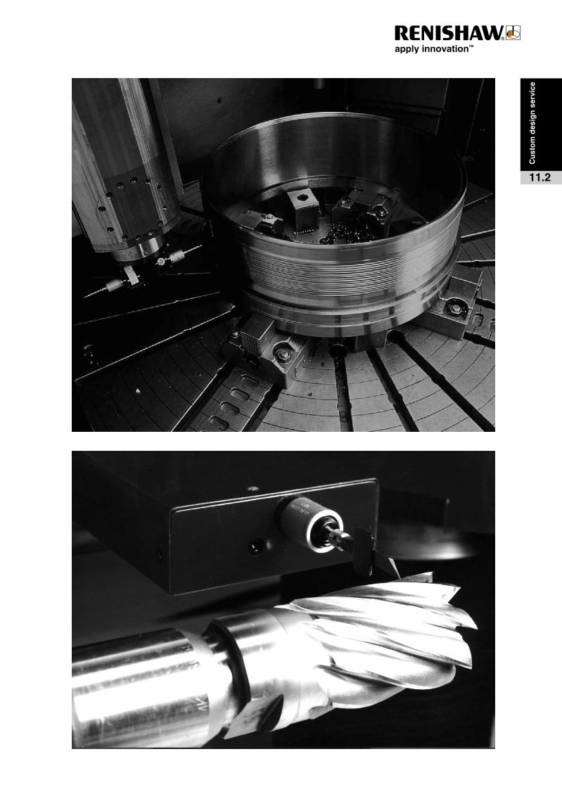
Cu
sto
m d
esig
n s
ervi
ce
11.2

Renishaw plc
New Mills, Wotton-under-Edge, Gloucestershire GL12 8JR United Kingdom
T +44 (0) 1453 524524 F +44 (0) 1453 524901 E [email protected]
www.renishaw.com
Printed in England 3.07 H-2000-3020-08-C
Renishaw applies innovation to provide solutions to your problemsRenishaw is an established world leader in metrology, providing high performance, cost-effective solutions for measurement and increased productivity. A worldwide network of subsidiary companies and distributors provides exceptional service and support for its customers.
Renishaw designs, develops and manufactures products which conform to ISO 9001 standards.
Renishaw provides innovative solutions using the following products:
• Probe systems for inspection on CMMs (co-ordinate measuring machines).
• Systems for job set-up, tool setting and inspection on machine tools.
• Scanning and digitising systems.
• Laser and automated ballbar systems for performance measurement and calibration of machines.
• Encoder systems for high accuracy position feedback.
• Spectroscopy systems for non-destructive material analysis in laboratory and process environments.
• Styli for inspection and tool setting probes.
• Customised solutions for your applications.
© 2001–2007 Renishaw plc. All rights reserved.
RENISHAW® and the probe emblem used in the RENISHAW logo are registered trademarks of Renishaw plc in the UK and other countries. apply innovation is a trademark of Renishaw plc.
Renishaw worldwide Australia
T +61 3 9521 0922 E [email protected]
Austria
T +43 2236 379790 E [email protected]
Brazil
T +55 11 4195 2866 E [email protected]
Canada
T +1 905 828 0104 E [email protected]
The People’s Republic of China
T +86 10 8448 5306 E [email protected]
Czech Republic
T +420 548 216 553 E [email protected]
France
T +33 1 64 61 84 84 E [email protected]
Germany
T +49 7127 981-0 E [email protected]
Hong Kong
T +852 2753 0638 E [email protected]
Hungary
T +36 23 502 183 E [email protected]
India
T +91 80 25320 144 E [email protected]
Israel
T +972 4 953 6595 E [email protected]
Italy
T +39 011 966 10 52 E [email protected]
Japan
T +81 3 5366 5315 E [email protected]
Malaysia
T +60 3 5631 4420 E [email protected]
The Netherlands
T +31 76 543 11 00 E [email protected]
Poland
T +48 22 577 1180 E [email protected]
Russia
T +7 495 231 1677 E [email protected]
Singapore
T +65 6897 5466 E [email protected]
Slovenia
T +386 1 527 2100 E [email protected]
South Korea
T +82 2 2108 2830 E [email protected]
Spain
T +34 93 663 34 20 E [email protected]
Sweden
T +46 8 584 90 880 E [email protected]
Switzerland
T +41 55 415 50 60 E [email protected]
Taiwan
T +886 4 2251 3665 E [email protected]
Thailand
T +66 2746 9811 E [email protected]
Turkey
T +90 216 380 92 40 E [email protected]
UK (Head Office)
T +44 1453 524524 E [email protected]
USA
T +1 847 286 9953 E [email protected]
For all other countries
T +44 1453 524524 E [email protected]