problem 15.4 the beam consists of material with e...
TRANSCRIPT

Problem 15.4 The beam consists of material withmodulus of elasticity E = 14x106 psi and is subjectedto couples M = 150, 000 in−lb at its ends. (a) What isthe resulting radius of curvature of the neutral axis? (b)Determine the maximum tensile stress due to bending?
Solution:The moment of inertia for the cross-section is:
I =πr4
4=
π(2in)4
4= 12.57in4
(a) Using Equation (15-10) to determine the magnitude of the radiusof curvature:
1ρ
=M
EI=
150, 000 in−lb
(14×106 lb/in2)(12.57 in4)= 8.524×10⁻⁴ in−1
ANS: ρ = 1173.2 in = 97.7 ft
Using Equation (15-12) to determine the applied moment:
σMAX =MyMAX
I=
(150, 000 in−lb)(2in)12.57 in4
ANS: σMAX = 23.9ksi
Problem 15.5 The material of the beam in Prob-lem 15.4 will safely support a tensile or compressivestress of 30, 000 psi. Based on this criterion, what is thelargest couple M to which the beam can be subjected?
Solution:Using Equation (15-12) to determine the applied moment:
σMAX =MyMAX
I→ M =
σMAXI
yMAX=
(30, 000 lb/in2)(12.57 in4)2 in
ANS: M = 188, 550 in−lb
Problem 15.6 The material of the beam in Prob-lem 15.4 will safely support a tensile or compressivestress of 30, 000 psi. If the beam has a hollow circularcross-section, with 2-in. outer radius and 1-in. innerradius, what is the largest couple M to which the beamcan be subjected?
Solution:The moment of inertia for the cross-section is:
I =π
4(r4
o − r4i ) =
π
4
[(2 in)4 − (1 in)4
]= 11.78 in4
Using Equation (15-12) to determine the applied moment:
σMAX =MyMAX
I→ M =
σMAXI
yMAX=
(30, 000 lb/in2)(11.78 in4)2 in
ANS: M = 176, 700 in−lb

Problem 15.7 Suppose that the beam in Example 15-1 is made of a brittle material that will safely supporta tensile stress of 20 MPa or a compressive stress of50 MPa. What is the largest couple M to which thebeam can be subjected?
Solution: From the solution to Example 15-1, we know that:
I = 1.85x10⁻⁶ m4
and
y = 0.0475 m
from the top of the cross-section.
Using the maximum tensile stress in Equation (15-12) to determine theallowable moment:
σMAX =MyMAX
I→ M =
σMAXI
yMAX=
(20×106 N/m2)(1.85×10−6 m4)0.08 m − 0.0475 m
M = 1138 N−m
Using the maximum compressive stress in Equation (15-12) to deter-mine the allowable moment:
σMAX =MyMAX
I→ M =
σMAXI
yMAX=
(50×106 N/m2)(1.85×10−6 m4)0.0475 m
M = 1947 N−m
We realize that the bar will fail if either of the calculated momentsis exceeded, so the maximum allowable moment must be the smallermoment.
ANS: M = 1138 N−m
Problem 15.8 What is the maximum tensile stress dueto bending in the beam in Example 15-2, and where doesit occur?
Solution:Summing moments about point B to determine the reaction at pointA:
ΣMB =[
12(w0)(L)
](L
3
)−Ay(L) → Ay = w0L/6 → By = w0L/3
The bending moment is maximum where the shear force equals zero.Summing vertical forces on an arbitrary length of the left-hand portionof the beam:
ΣFy = 0 =w0L
6−[
12
w0
Lx
](x)
ANS: x = 0.577L at the bottom of the cross-section
Summing moments on the free-body diagram at x = 0.577L:
M = −(
w0L
6
)(0.577L)+
[12
(w0
L
)(0.577L) (0.577L)
](0.577L
3
)
M = w0L2(−0.064)
Using Equation (15-12) to determine the bending stress:
(σT )MAX =My
I=
0.064w0L2 (h/2)(h(h)3/12)
ANS: (σT )MAX = 0.384w0L2
h3
Free Body Diagram:
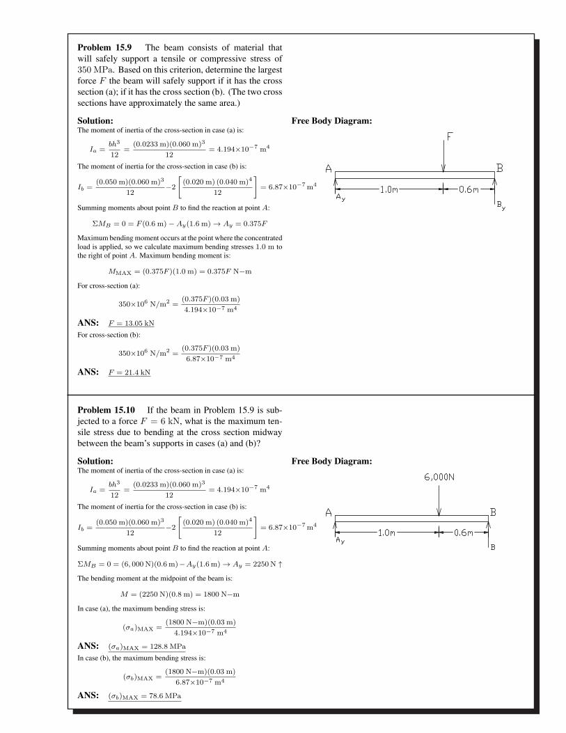
Problem 15.9 The beam consists of material thatwill safely support a tensile or compressive stress of350 MPa. Based on this criterion, determine the largestforce F the beam will safely support if it has the crosssection (a); if it has the cross section (b). (The two crosssections have approximately the same area.)
Solution:The moment of inertia of the cross-section in case (a) is:
Ia =bh3
12=
(0.0233 m)(0.060 m)3
12= 4.194×10⁻⁷ m4
The moment of inertia for the cross-section in case (b) is:
Ib =(0.050 m)(0.060 m)3
12−2
[(0.020 m) (0.040 m)4
12
]= 6.87×10⁻⁷ m4
Summing moments about point B to find the reaction at point A:
ΣMB = 0 = F (0.6 m) − Ay(1.6 m) → Ay = 0.375F
Maximum bending moment occurs at the point where the concentratedload is applied, so we calculate maximum bending stresses 1.0 m tothe right of point A. Maximum bending moment is:
MMAX = (0.375F )(1.0 m) = 0.375F N−m
For cross-section (a):
350×106 N/m2 =(0.375F )(0.03 m)4.194×10⁻⁷ m4
ANS: F = 13.05 kN
For cross-section (b):
350×106 N/m2 =(0.375F )(0.03 m)6.87×10⁻⁷ m4
ANS: F = 21.4 kN
Free Body Diagram:
Problem 15.10 If the beam in Problem 15.9 is sub-jected to a force F = 6 kN, what is the maximum ten-sile stress due to bending at the cross section midwaybetween the beam’s supports in cases (a) and (b)?
Solution:The moment of inertia of the cross-section in case (a) is:
Ia =bh3
12=
(0.0233 m)(0.060 m)3
12= 4.194×10⁻⁷ m4
The moment of inertia for the cross-section in case (b) is:
Ib =(0.050 m)(0.060 m)3
12−2
[(0.020 m) (0.040 m)4
12
]= 6.87×10⁻⁷ m4
Summing moments about point B to find the reaction at point A:
ΣMB = 0 = (6, 000 N)(0.6 m)−Ay(1.6 m) → Ay = 2250 N ↑The bending moment at the midpoint of the beam is:
M = (2250 N)(0.8 m) = 1800 N−m
In case (a), the maximum bending stress is:
(σa)MAX =(1800 N−m)(0.03 m)
4.194×10⁻⁷ m4
ANS: (σa)MAX = 128.8 MPa
In case (b), the maximum bending stress is:
(σb)MAX =(1800 N−m)(0.03 m)
6.87×10⁻⁷ m4
ANS: (σb)MAX = 78.6 MPa
Free Body Diagram:

Problem 15.12 The beam is subjected to a uniformlydistributed load w0 = 300 lb/in. Determine the max-imum tensile stress due to bending at x = 20 in if thebeam has the cross section (a); if it has the cross (b). (Thetwo cross-sections have approximately the same area.)Free Body Diagram:
Solution:The moments of inertia for the cross-sections in the two cases are:
Ia =(4.47 in)(4.47 in)3
12= 33.27 in4
Ib =(6 in)(6 in)3
12− (4 in)(4 in)3
12= 86.67 in4
Equilbiruim to find Ay + By
Free Body Diagram:
ΣMB = 0 = Ay(85) − 25, 500(42.5)
ANS: Ay = 12, 500 N
Summing moments about the cut through the beam at x = 20 in:
M = (12, 750 lb)(20 in) − (6, 000 lb)(10 in) = 195, 000 in−lb
We see that the maximum tensile occurs at the bottom of each cross-section.
In case (a), the maximum tensile stress is:
(σT )MAX =(195, 000 in−lb) (4.47 in/2)
33.27 in4
ANS: (σT )MAX = 13.1 ksi at the bottom of the cross-section
In case (b), the maximum tensile stress is:
(σT )MAX =(195, 000 in−lb)(3in)
86.67 in4
ANS: (σT )MAX = 6.75 ksi at the bottom of the cross-section
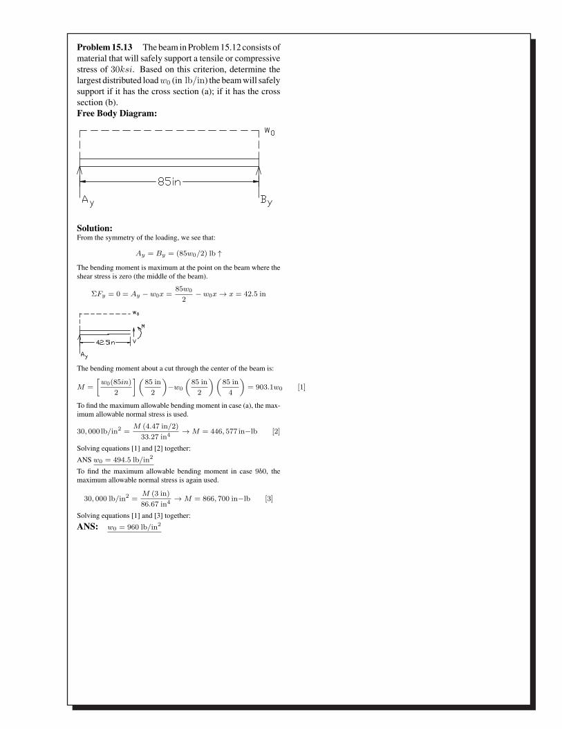
Problem 15.13 The beam in Problem 15.12 consists ofmaterial that will safely support a tensile or compressivestress of 30ksi. Based on this criterion, determine thelargest distributed load w0 (in lb/in) the beam will safelysupport if it has the cross section (a); if it has the crosssection (b).Free Body Diagram:
Solution:From the symmetry of the loading, we see that:
Ay = By = (85w0/2) lb ↑The bending moment is maximum at the point on the beam where theshear stress is zero (the middle of the beam).
ΣFy = 0 = Ay − w0x =85w0
2− w0x → x = 42.5 in
The bending moment about a cut through the center of the beam is:
M =[
w0(85in)2
](85 in
2
)−w0
(85 in
2
)(85 in
4
)= 903.1w0 [1]
To find the maximum allowable bending moment in case (a), the max-imum allowable normal stress is used.
30, 000 lb/in2 =M (4.47 in/2)
33.27 in4 → M = 446, 577 in−lb [2]
Solving equations [1] and [2] together:
ANS w0 = 494.5 lb/in2
To find the maximum allowable bending moment in case 9b0, themaximum allowable normal stress is again used.
30, 000 lb/in2 =M (3 in)86.67 in4 → M = 866, 700 in−lb [3]
Solving equations [1] and [3] together:
ANS: w0 = 960 lb/in2
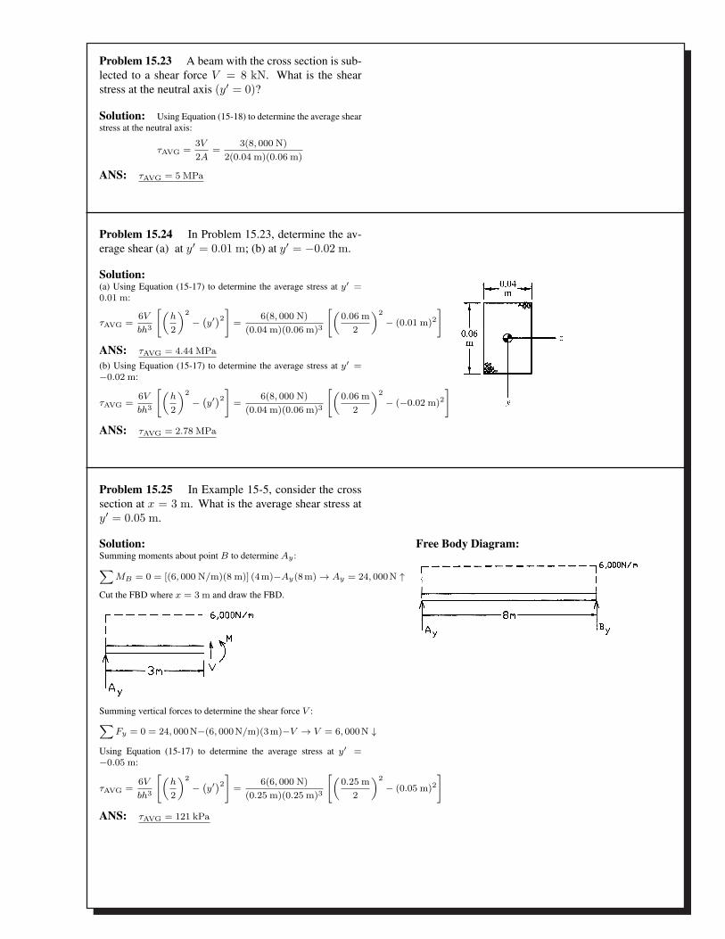
Problem 15.23 A beam with the cross section is sub-lected to a shear force V = 8 kN. What is the shearstress at the neutral axis (y′ = 0)?
Solution: Using Equation (15-18) to determine the average shearstress at the neutral axis:
τAVG =3V
2A=
3(8, 000 N)2(0.04 m)(0.06 m)
ANS: τAVG = 5 MPa
Problem 15.24 In Problem 15.23, determine the av-erage shear (a) at y′ = 0.01 m; (b) at y′ = −0.02 m.
Solution:(a) Using Equation (15-17) to determine the average stress at y′ =0.01 m:
τAVG =6V
bh3
[(h
2
)2− (y′)2] =
6(8, 000 N)(0.04 m)(0.06 m)3
[(0.06 m
2
)2− (0.01 m)2
]
ANS: τAVG = 4.44 MPa
(b) Using Equation (15-17) to determine the average stress at y′ =−0.02 m:
τAVG =6V
bh3
[(h
2
)2− (y′)2] =
6(8, 000 N)(0.04 m)(0.06 m)3
[(0.06 m
2
)2− (−0.02 m)2
]
ANS: τAVG = 2.78 MPa
Problem 15.25 In Example 15-5, consider the crosssection at x = 3 m. What is the average shear stress aty′ = 0.05 m.
Solution:Summing moments about point B to determine Ay :∑
MB = 0 = [(6, 000 N/m)(8 m)] (4m)−Ay(8m) → Ay = 24, 000N ↑Cut the FBD where x = 3 m and draw the FBD.
Summing vertical forces to determine the shear force V :∑Fy = 0 = 24, 000N−(6, 000N/m)(3m)−V → V = 6, 000N ↓
Using Equation (15-17) to determine the average stress at y′ =−0.05 m:
τAVG =6V
bh3
[(h
2
)2− (y′)2] =
6(6, 000 N)(0.25 m)(0.25 m)3
[(0.25 m
2
)2− (0.05 m)2
]
ANS: τAVG = 121 kPa
Free Body Diagram:
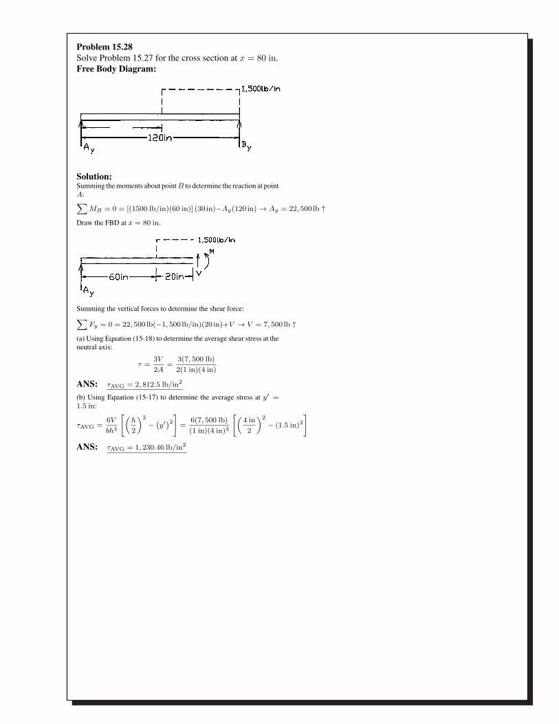
Problem 15.28Solve Problem 15.27 for the cross section at x = 80 in.Free Body Diagram:
Solution:Summing the moments about point B to determine the reaction at pointA:∑
MB = 0 = [(1500 lb/in)(60 in)] (30 in)−Ay(120 in) → Ay = 22, 500 lb ↑Draw the FBD at x = 80 in.
Summing the vertical forces to determine the shear force:∑Fy = 0 = 22, 500 lb(−1, 500 lb/in)(20 in)+V → V = 7, 500 lb ↑
(a) Using Equation (15-18) to determine the average shear stress at theneutral axis:
τ =3V
2A=
3(7, 500 lb)2(1 in)(4 in)
ANS: τAVG = 2, 812.5 lb/in2
(b) Using Equation (15-17) to determine the average stress at y′ =1.5 in:
τAVG =6V
bh3
[(h
2
)2− (y′)2] =
6(7, 500 lb)(1 in)(4 in)3
[(4 in2
)2− (1.5 in)2
]
ANS: τAVG = 1, 230.46 lb/in2

Problem 15.29 What is the maximum magnitude ofthe average shear stress in the beam in Problem 15.27,and where does it occur?Free Body Diagram:
Solution:Summing the moments about point B to determine the reaction at pointA:∑
MB = 0 = [(1500 lb/in)(60 in)] (30 in)−Ay(120 in) → Ay = 22, 500 lb ↑ By = 67, 500 lb ↑We see that the maximum shear stress exists at x = 120 in.ANS: V = 67, 500 lb ↑(a) Using Equation (15-18) to determine the average shear stress at theneutral axis:
τ =3V
2A=
3(67, 500 lb)2(1 in)(4 in)
ANS: τAVG = 25, 312, 5 lb/in2 = 25.3 kip/in2
Problem 15.30 By integrating the stress distributiongiven by Equation (15-17), confirm that the total forceexerted on the rectangular cross section by the shearstress is equal to V .
Solution:Starting with Equation (15-17) and integrating over the dimensions−h/2 to h/2:
τAVG =6v
bh3
∫ h/2
−h/2
[h2
2= (y′)2
]dA
=6v
bh3
∫ h/2
−h/2
[h2
2= (y′)2
]bdy
=6vb
bh3
∫ h/2
−h/2
[h2
2= (y′)2
]dy
Doing the integration:
τAVG =6v
h3
[(h2y′
4− (y′)3
3
)]h/2
−h/2
τAVG =6v
h3
[(h3
8− h3
24
)−(−h3
4− −h3
24
)]
τAVG =6v
h3
[h3
4− −h3
12
]=
6v
h3
[h3
6
]
ANS: τAVG = V
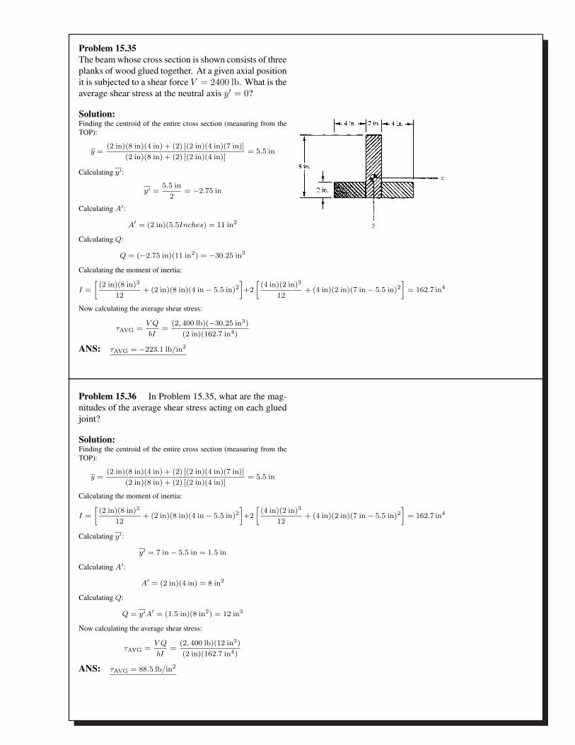
Problem 15.35The beam whose cross section is shown consists of threeplanks of wood glued together. At a given axial positionit is subjected to a shear force V = 2400 lb. What is theaverage shear stress at the neutral axis y′ = 0?
Solution:Finding the centroid of the entire cross section (measuring from theTOP):
y =(2 in)(8 in)(4 in) + (2) [(2 in)(4 in)(7 in)]
(2 in)(8 in) + (2) [(2 in)(4 in)]= 5.5 in
Calculating y′:
y′ =5.5 in
2= −2.75 in
Calculating A′:
A′ = (2 in)(5.5Inches) = 11 in2
Calculating Q:
Q = (−2.75 in)(11 in2) = −30.25 in3
Calculating the moment of inertia:
I =[
(2 in)(8 in)3
12+ (2 in)(8 in)(4 in − 5.5 in)2
]+2[
(4 in)(2 in)3
12+ (4 in)(2 in)(7 in − 5.5 in)2
]= 162.7 in4
Now calculating the average shear stress:
τAVG =V Q
bI=
(2, 400 lb)(−30.25 in3)(2 in)(162.7 in4)
ANS: τAVG = −223.1 lb/in2
Problem 15.36 In Problem 15.35, what are the mag-nitudes of the average shear stress acting on each gluedjoint?
Solution:Finding the centroid of the entire cross section (measuring from theTOP):
y =(2 in)(8 in)(4 in) + (2) [(2 in)(4 in)(7 in)]
(2 in)(8 in) + (2) [(2 in)(4 in)]= 5.5 in
Calculating the moment of inertia:
I =[
(2 in)(8 in)3
12+ (2 in)(8 in)(4 in − 5.5 in)2
]+2[
(4 in)(2 in)3
12+ (4 in)(2 in)(7 in − 5.5 in)2
]= 162.7 in4
Calculating y′:
y′ = 7 in − 5.5 in = 1.5 in
Calculating A′:
A′ = (2 in)(4 in) = 8 in2
Calculating Q:
Q = y′A′ = (1.5 in)(8 in2) = 12 in3
Now calculating the average shear stress:
τAVG =V Q
bI=
(2, 400 lb)(12 in3)(2 in)(162.7 in4)
ANS: τAVG = 88.5 lb/in2