problems in pressure vessel design and manufacture
TRANSCRIPT

AE-104
Problems in Pressure Vessel Design and Manufacture
0. Hellstrom Ragnar Nilson
AKTIEBOLAGET ATOMENERGISTOCKHOLM SWEDEN 1963


AE-104
PROBLEMS IN PRESSURE VESSEL DESIGN AND MANUFACTURE.
O® Hell strOm Ragnar Nil sonUDDEHOLMS AB, DEGERFORS JARNVERK AB ATOMENERGI
Degerfors Stockholm
AbstractThe general desire by the power reactor process makers to in
crease power rating and their efforts to involve more advanced thermal behaviour and fuel handling facilities within the reactor vessels are accompanied by an increase in both pressure vessel dimensions and various difficulties in giving practical solutions of design, materials and fabrication problemsa In any section of this report it is emphasized that difficulties and problems already met with will meet again in the future vessels but then in modified forms and in many cases more pertinent than before* As for the increase in geometrical size it can be postulated that with use of better materials and adjusted fabrication methods the size problems can be taken proper care of* It seems likely that vessels of sufficient large diameter and height for the largest power output, which is judged as interesting in the next ten year period, can be built without developing totally new site fabrication technique® It is, however, supposed that such a fabrication technique will be feasible though at higher specific costs for the same quality requirements as obtained in shop fabrication®
By the postulated use of more efficient vessel material with principally the same good features of easy fabrication in different stages such as preparation, welding, heat treatment, etc as ordinary or slightly modified carbon steels the increase in wall thickness might be kept low® There exists, however, a development work to be done for low-alloy steels to prove their justified use in largo reactor pressure vessels,: ■
Paper presented to the EAES Symposium "KEY PROBLEMS OF NUCLEAR POWER STATIONS LIKELY TO BE BUILT DURING THE NEXT TEN YEARS" at Cannes, France, 8-12 October 1962,Printed and distributed in May 1963,
CONTENTS
Page
Introduction 3Survey of Swedish Reactor Vessels 61, Agesta PHWR Vessel 62. Marviken BHWR Vessel 93* Project study PHWR-400 Vessel 1 14. Project study Bashful-500 Vessel 12Vessel steels and strength evaluation 14Fabrication in shop or at site 18Special shop requirements due to size, weight and design
of the vessel 19Shop fabrication and inspection 20Summary 24Figures 1 - 27 I - XVIII
REFERENCE REMARKThis paper is of course only one contribution among many to a more complete picture of the Swedish development work for nuclear power stations. At the Cannes symposium other important development problems are stated in the following paper: "Major Problems and Development Tests for Heavy Water Pressure Vessel Reactors" by P H Margen.

- 3 -
Introduction
The nuclear power reactor development work in Sweden has since 1958 been lined up with practically total concentration upon heavy water reactors of the pressure vessel design type. The first demonstration of this reactor type in Sweden, the Agesta PHWR reactor is now in the
later stages of construction and will finally be put in order for criticality and the following research program of first core physics and thermal behaviour and further stepwise increasing power production tests in the beginning of 1963, This reactor has been described at different occasions during the last years at conferences and in technical magazines and in this report design features by its vessel are given mainly
in order to create a reference point in the discussion of design and manufacture problems by large reactor pressure vessels. Problems of various kinds which has been treated and brought to practical solutions
in the different stages of the work upon the Agesta vessel are doubtless forming a fertile ground in the work with the following pressure vessels which since some time are brought to more or less detailed pre-project
studies for our future power reactor program. From the general point of view the Agesta reactor - in itself too small and in many features
suspected to be too complicated and technologically too "luxurious" to be claimed an economical power production unit - might be regarded
as starting point for two attractive outlines of pressure vessel unit developments for competitive nuclear power, namely
a) the uniform lattice reactor ("homogenized"), PHWR, and
b) the natural circulation direct cycle boiling reactor equipped with facilities for nuclear superheating, BHWR.
Both these reactors are studied for electricity outputs up to the order of 400 to 500 MWe and the consequenses in design and manufacturing of the adequate pressure vessels are considered. It can be seen from the following report, that even if the Agesta vessel must be re
garded as large and heavy the vessels required for the future reactors are still larger. With respect to most factors which influence the

judgment of their feasibility really important extrapolations of the
engineering achievements of today have to be established.
In the question of which reactor pressure vessel is likely to be built next in Sweden it might be pointed out that a redesign work of the Marviken Power Plant according to an BHWR lay-out is now going on for an output size of 200 MWe - when internal nuclear superheating is included - and that a formal decision on construction can be expected
during the first months of 1963. Planned date for power operations
of this unit is 1968. Full scale units - about 500 MWe output - of BHWR or PHWR might in Sweden be requested for commercial operation in the beginning of the 1970's.
Before going over to the more detailed descriptions of the different problems it might be proper to lay down some background aspects for heavy vessels for nuclear reactor purpose. Design, manufacturing,
inspection and use of pressure vessels for different purposes are in most countries subjected to more or less rigorous regulations and the
application within a new field is consequently among other always regarded from the "Pressure Vessel Code" point of view. In 1956 the regulation aspects in USA were brought to a more common formal basis
by the establishing of the AS ME Boiler and Pressure Vessel Code Interpretation Case No 1224 (Special Ruling), which then time to another was completed by definitions and addenda.
In the beginning of 1958 the tentative regulations were brought together in Case No 1234, which gives the Code aspects upon all pressure vessels working in the primary reactor circuit or aside from that in such circuits which still carry reactor coolant containing lethal substances. Quotation from the interpreta,tion Case No 1234 is made here;
"inquiry; Under what special rules shall a nuclear reactor vessel or a primary vessel, as defined in Case No 1224, be built in order to be built in order to be acceptable for Code construction?

Reply: Pending development of more complete rules to cover
nuclear vessels, it is the opinion of the Committee that a reactor vessel or a primary vessel shall meet the requirements of this Case in order to meet the intent of the Code and to be stamped in accordance
with Case No 1224. Where differences exist the requirements of this Case take precedence over the Code rules for the subjects covered.The requirements of this Case are as follows: (l), (2) -----(6), (7) and (8)."
The design, calculation, general specification of materials, welding fabrication and inspection rules given in the items (1) to (6) are quite well defined additions to and restrictions of normal Code regulations and do not cause much trouble in their interpretation and
technical application.
The items (7) and (8) are of quite another character and do in fact contain general descriptions of what to be taken special care of when designing advanced vessels, specially nuclear vessels. Quota
tion follows here;
"(7) The Code rules are intended to provide minimum safety requirements for new construction, and not to cover deterioration
which may occur in service as a result of corrosion, erosion, radiation effects, instability of the material, or operating conditions such as transient thermal stress or mechanical shock and vibratory loading; nevertheless particular consideration shall be given to these
effects with a view of obtaining the desired life of the vessel.
(8) In view of these severe service requirements, particular consideration shall also be given to materials, construction, and
inspection, including supplementary methods of non-destructive testing, so that soundness and good practice will result. Due regard shall be given to such items as smoothness of welds and to location
and detail of structural attachments. "
- 6 -
Since 1958 there has of course been added more detailed provisional rules and recommendations both by the AS ME Boiler and Pressure Vessel Committee and by safeguard authorities and
societies in other countries,for instance by Lloyd's Register of
Shipping, Land Division, in the Provisional Requirements, I960.These rules - later on collected for instance within the AS ME Nuclear Code Cases No 1270 N, 1271 N, 1272 N, 1273 N, 1274 N and their addenda - do still mostly refer to problems of the same
defined character as covered by the items (1) to (6) above and the items (7) and (8) still are in principle as generally given as in 1958.It is easy to see that the problems which are not distinctly covered
by Code rules may cause the engineer more trouble than those which are covered. It is further quite obvious that the questions which are not covered by Code rules may have a great and perhaps dominant effect upon fabrication and construction costs.
As the evaluation of all these questions on the basis of experienced correlations between used design and intended vessel usage and real vessel behaviour during operation still is poor or lacking, it must be stated that sufficient background for a verified economically optimized design work does not yet exist.
Survey of Swedish Reactor Vessels
A schematic study in size growth for these vessels is demonstrated in Fig. 15 on figure page XIII after the text.
2 - _-Ag e s ta JPTTW_R_V e s s e 1
The Agesta reactor vessel is shown in Fig, 1, 2, 3 and 4 - figure
pages I - IV after the text - and the principle data are to be found in
table 1 at the end of this survey chapter on page 13. Specially interesting parts of the vessel are: .
- 7 -
Bottom dome is of ellipsoid!cal shape with the main nozzles for
inlet and outlet of the coolant. Originally this dome was assumed to be made with a spherical crown radius for the central portion and with a
torus radius for the outer knuckle portion. From extensive strain measuring on a scale model, however, it was gathered that the combination of large nozzles and their full reinforcement would give
stresses of somewhat irritating magnitude for a nuclear vessel. As a
result the shape was changed to ellipsoidical which was judged to give diminished stresses particularly around the nozzles. The theoretical examination was confirmed by the strain measurement results obtained
for the full scale vessel in connection with the final pressure test.
The flat top cover is equipped with light water circulation for balanced heating and cooling guided by and controlled against the reactor coolant temperature. The height of top cover is dictated not only by the need to keep weld seam stresses low but also by the requirement that radiation dose should be kept at low rates for the upper closing plate and the tightening flange so that the top plate could be accessible
whenever the reactor is shut down.
The top cover is penetrated by standpipes for fuelling operation and application of control rod drives. As this reactor has intermittent
fuelling operation at rather short intervals the standpipe closures will be handled quite many times (roughly 200) during the desired total opera
tional lifetime. If these closures are maintainable at non-leakage conditions will be an interesting experience.
The special flange design - the type is shown in Fig. 8 - which permits reactor starting-up and shut-down operations performed within
10 hours each without producing any overstresses in neither the vessel nor the top cover, The flange in itself is tightened by a primary lensformed silver gasket and a secondary seal-welded torus.
All the internal vessel equipment - shielding komponents and water distribution box etc. - is adapted for remote handling by special
- 8 -
decomposition and lifting gages and the vessel itself can be remote control lifted out of the concrete biological shielding.
A delicate problem was formed by the demand for very narrow tolerances for vessel roundness and axial alignment.
All heavy water wet surfaces are claimed to be stainless steel clad and surface finish in order to prevent contamination was demanded
to be high quality, microdepth of profile in the order of 0*016 mm. The stainless cladding was permitted to be supplied as roll-clad or as
deposit weld clad,
A special feature which might be regarded as quite conservative is the arrangement of neutron and thermal shielding. The radial shielding is made from stainless steel cylindrical shells concentrically placed with a very thin annular ring space between and are together forming 1 50 mm steel between the outer radius of the core reflector and the vessel wall. Thus the integrated irradiation dose on the wall will be quite modest even for a core of higher thermal power than the actual one. Furthermore special channels for boxes containing test pieces of vessel steel are arranged in the outer portion of the radial stainless steel shielding. This boxes are remotely handled by a special machine for removal and transport to test facilities, where control results of irradiation embrittlement of the vessel steel can be obtained from time to time.
In order to verify intended design decisions different component investigations were carried out. One of these investigations is represented here by Fig. 10, showing scale model of the vessel. That model was investigated for stress concentrations in the different parts of tank and lid and subjected to pressure cycling in order to verify the leak tightness of the primary silver gasket arrangement. Bottom dome
shape modification was initiated by the test results. Another study is
shown in Fig. 11, which illustrates a detailed study of a flat lid portion

- 9 -
including the part of the standpipe which penetrates the lid. Investigation of stresses and deformations behaviour under thermal cycling and
examination of welding procedure were the preset aims of this work,
which gave some valuable hints to detail modifications.
2. _ Marvikeri BHWR__Vessel
The Marviken reactor is just now - as mentioned in the introduction of this report - in a redesign period. The reactor vessel is
shown in Fig. 5, 6, 7 and 8 - figure pages V - VIII after the text - and the principal data are listed in table 1 on page 13. All features given in this report belong to the redesign version although some of them, e. g. the internal fuel element manipulator, which gives the vessel height, can be found in an earlier PHWR version for Marviken.
While the Agesta vessel has a lot of standpipes for refuelling the Marviken vessel is equipped with only one loading channel penetration. As the control rod hydraulic drives are arranged internally
at the top of core shroud, penetrations for these drive units are
eliminated from the vessel itself. The cylindrical vessel shell is penetrated by feed water piping for control rod drives, medium sized steam piping for pressure relief valves, small size piping for emergency cooling of boiler fuel elements and fuel canning leak detection and medium sized piping for emergency cooling of superheater fuel elements. Those penetrations can be assembled within a rather localized cylinder shell ring portion which has to be reinforced by increase
of wall thickness. Outside of that region the cylinder shell is quite clean and straight.
The severe penetrations problems are concentrated to the bottom
dome where 30 superheater nozzles and some other single position penetrations are arranged. The bottom dome design and manufacture will undoubtly form a work of highest,qualification and careful studies of what should be the detailed technical decisions are underway. Among
10 -
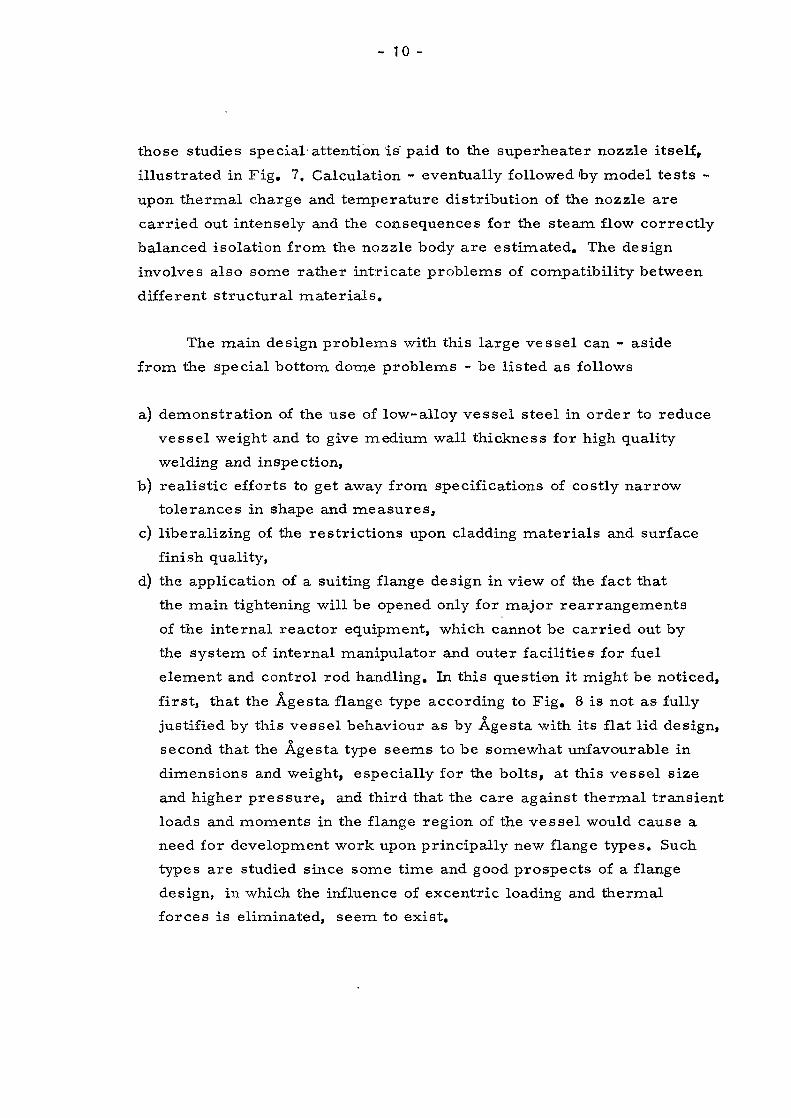
those studies special attention is paid to the superheater nozzle itself,
illustrated in Fig. 7, Calculation - eventually followed by model tests -
upon thermal charge and temperature distribution of the nozzle are carried out intensely and the consequences for the steam flow correctly balanced isolation from the nozzle body are estimated. The design
involves also some rather intricate problems of compatibility between different structural materials.
The main design problems with this large vessel can - aside from the special bottom dome problems - be listed as follows
a) demonstration of the use of low-alloy vessel steel in order to reduce vessel weight and to give medium wall thickness for high quality
welding and inspection,b) realistic efforts to get away from specifications of costly narrow
tolerances in shape and measures,c) liberalizing of the restrictions upon cladding materials and surface
finish quality,d) the application of a suiting flange design in view of the fact that
the main tightening will be opened only for major rearrangements
of the internal reactor equipment, which cannot be carried out by the system of internal manipulator and outer facilities for fuel element and control rod handling. In this question it might be noticed, first, that the Agesta flange type according to Fig. 8 is not as fully justified by this vessel behaviour as by Agesta with its flat lid design, second that the Agesta type seems to be somewhat unfavourable in
dimensions and weight, especially for the bolts, at this vessel size
and higher pressure, and third that the care against thermal transient loads and moments in the flange region of the vessel would cause a need for development work upon principally new flange types. Such types are studied since some time and good prospects of a flange design, in which the influence of excentric loading and thermal forces is eliminated, seem to exist.

In this reactor vessel the neutron and thermal shielding is acquired by a somewhat different arrangement than by the Agesta vessel. Theore
tical and experimental research has given verifying contribution to this
arrangement, which will use a comparatively thin radial stainless steel
shield combined with a thicker layer of heavy water between the steel shield and the vessel wall. The efficiency of this method seams to be
superior to that of using thick stainless steel shielding with exception
for the fact that an increase in heavy water inventory could result.The width of the annular ring space for heavy water outside of the steel shielding is, however, in this case also needed for the thermal process water flow. It can be foreseen that the arrangement of test specimen
channels for time to time watching of the irradiation damage on vessel wall steel would still be kept as an operation condition for this vessel as it is for the Agesta vessel.
3, _Projekt_ study PHWR-400_Vessel
A principal drawing of this pressure vessel is shown in Fig, 9 - figure page IX after the text - and the principle data are listed in table 1 on page 13 . Special features for this vessel are
a) top dome lid is to be removed at each fuel handling occasion as the reactor
is projected to have a fuel handling procedure similar to that of light water reactors,
b) hemispherical bottom dome design requires some considerations with
respect to the main inlet and outlet nozzles which are positioned upin the cylinder flange region of the dome. The control rod drive penetrations in the central zone of the hemisphere would not give major trouble.
As these technical applications have been verified in rather many cases before this study it seems correct to postulate that most of the considerations will be reiterated verification of the soundness and good
sense in design modifications initiated by different manufacturing methods.

-12-
In addition some development work might be included upon more exact
calculation methods for reinforcements in transition regions disturbed by bending moments.
4, Project study Bashful-500 Vessel
The reactor vessel of this study appears in this report mostly in
table 1 on page 13, where the principal data are given for comparison with Marviken BHWR.
Table 2 on page 17 shows some speculations around needed vessel wall thicknesses by the use of different vessel steels.

13 -
Table 1. Survey of Reactor Data
Agesta Marviken Project ProjectPHWR BHWR Study Study
PHWR-400 Bashful-500
Core diameter m 3, 61 4, 90 4, 66 4. 83Core height m 3. 04 5. 02 5. 50 4. 83
Radial reflector m 0.3 0.3 0. 3 0. 33
Top " m 0.3 0.3 0. 3 0. 33
Bottom " m - °. 3 0. 3 0.3 0.33Core thermal output MW / 65
1(125) 570 1200 1360
Design pressure bar 40 57. 5 80 77" temperature °C 251 272 293 291
Saturated steam temp. °C 263 283Superheated steam " °C
Shielding radial thickness in
500 500
Stainless steel mm 150 50 90 (-70)
Heavy water mm 21 110 130 (-45)
Irradiation flux at vessel wall n/crn^ sek
(E - 1 MeV)
91.2 * 107
92)3-4 • lcr
,2)4.2 • ur
,2)—4-6 • 10
Vessel inner diameter m 4. 555 5. 22 5. 10 5.72
Cylindrical shellthickness in vessel ■steel mm 65 61 90 98
Vessel steel ^ ^ carbon-manganese
low-alloy low-alloy low-alloy
Vessel height m 9. 5 22. 1 14. 0 24. 0373)Control rod positions 27 + 2 303) 12
Fuel element handling f top lidpenetrations
Superheater penetrations in37 1 Y removal 1
bottom dome 30 40
1) Steels according to Table 2,2) Estimated values3) Not penetrating the vessel
page 17.

14
Vessel steels and strength evaluation
In Fig. 12 the specification for the Agesta vessel steel is given and
in Fig. 13 the impact qualities of the virgin material before fabrication are demonstrated. From most aspects this steel is quite wellknown beeing a fine grain treatment modification of a Swedish standardized
pressure vessel steel. The requirement of extraordinary low cobolt content for nuclear use is representative for the period when the Agesta
specification was decided. From table 2 and Fig, 14, however, it can
be read that the continued use of a vessel steel with such modest strength values would cause rather high wall thickness and as a result of that quite impossible vessel component weight especially by the larger vessels. The welding procedures and effective inspection possibilities
are also seriously negatively affected by increasing wall thickness. The evaluation of thermal stresses resulting from blocked transient thermal strains is also considered to give strong arguments against thick materials. It is then an automatic consequence that steels with higher strength values and still preserved good behaviour in fabrication and use must be given keen attention. The strength calculation values,38 - 41 kp/mm^ at actual design temperatures, given in table 2, are
representative for low-alloy vessel steels obtainable from Swedish steel-makers today. For the Marviken BHWR reactor vessel the design and manufacturing pretest work with the Fortiweld Normal steel is now going on. This is a boron micro-alloyed fine grain treated carbon
steel and gives in normalized condition a yield point value of minimum 45 kp/mm.2 at room temperature and is since some years used in
comparatively large conventional pressure vessels. As for Charpy2
impact values this steel is specified for guarantee of 3. 5 kpm/cm (25 ft. lbs) at 0 °C. For ordinary carbon vessel steels the specified
Charpy impact value according to the Swedish Pressure Vessel Code is 2.6 kpm/cm^ (15 ft.lbs) at -20 °C.
As can be computed from estimated neutron flux data in table 1 the integrated irradiation damage dose (E > 1 MeV) upon the vessel wall for the Marviken BHWR reactor would be in the order of 3 • 10^ ^n/em ^

15
at 30 years total life time and utilisation rate of 80 %. According to preliminary results from irradiation tests upon this steel this integrated dose might give a fairly large contribution to the rise of brittle
fracture propagation transition temperature. It is today a bit early to state wether this would cause special requirements as to the operation conditions for the reactor. If, however, the safeguard evaluation of the embrittling behaviour would tend to give severe restrictions in the operational schedule it seems likely that a medium-strength vessel steel would be chosen this time. Basical experiments and evaluation work have to be done in order to establish
more explicit use of the scattered and un-correlated knowledge of irradiated steel behaviour.
The calculation and evaluation of strength conditions for the
ductile behaviour of reactor vessel steels are in some respects carried out with more care than what is prescribed by pressure vessel codes applied upon ordinary vessel with dangerous contents. With
respect to undisturbed membrane stresses and mean stress values the considerations have given the result that no argument exists for a more conservative attitude. The unofficial provisional requirements
used as additions within this work are specifically valid for thermal transient stresses and bending stresses. The following list of factors which can form different patterns for the evaluation of safety factors gives the situation?
Type of loading,Uncertainly in load evaluation,Inherent stress conditions,Real correlation stress verses strain,Multiaxial stress-strain correlations (plastic yield behaviour criteria), Deformation hardening and Bauschinger effect,Relaxation (creep at low temperatures),Low cycle fatigue,Corrosion,Normally existing material defects,Faultive material,Influence of fabrication tolerances,

- 16-
Compatibility between different materials,Degree of statical indeterminate condition,Uncertainly in computing methods.
The value of such a rather comprehensive evaluation model depends entirely upon, first real knowledge of reactor operating conditions and second,upon well correlated practical and experimental experience from vessel behaviour as well in design details as in
material characteristics.

- 17 -
Table 2. Reactor Vessel Datai |
AgestaPHWR
PHWR--400
Marviken--BHWR
B ashful - -500
1. Design pressure bar 40 80 57.5 772*. Design temperature °C 250 293 272 2913. Inner diameter m 4. 555 5. 10 5.22 5.724. Vessel steel type carbon- ,x
manganeselow- alloy'6)
low- alloy ^
low- -x alloy'
5, Cylindrical wall thickness*?'(exclusive cladding material)
mm 65 90 61 98
6. Bottom dome wall thickness •
mm 65 905) 95 165
ALTERNATIVE
5. 1 Cylindrical wall thickness for steel according to note 1)
mm 65 165 114 180
5. 2 Cylindrical wall thickness for low- alloy steel according to note 4)
mm 75 52 80
1) Stress calculation value at actual design temperature 24 kp/mm^
2) 11 It u M 11 II tl 38 11
3) M ir n tl It n n 41 11
4) M it it 11 If ri ti 46 ft
5) Hemispherical shape
6) Allowable hoop stress calculation according to the Swedish Pressure Vessel Code, 1959.

- 18 -
Fabrication in shop or at site
The size development of heavy water reactor pressure vessels in Sweden during the next ten years has already been described, Fig. 15, The rapid increase of the over all dimensions and weights needs a careful investigation of the suitableness of fabricating the vessel in shop, at site or a combination of the two. A survey of the requirements for a
heavy water reactor pressure vessel as to weld procedure, machining, tolerances, final assembly, testing and adjusting gives a distinct advantage for shop fabrication. Further it is good reason for a statement
that a complete site erection from pressed plates similar to the fabrication of gas cooled reactors in England is more or less impossible. These facts give rise to the conclusion that a combined fabrication in shop and at site presupposes that the site must be equipped with a
fabrication shop for putting together largest possible prefabricated
components. Such a shop at site must have facilities for welding, machining, lifting, stress relieving etc, A good example of this combined fabrication is the twelve 350 tons heat exchangers for
Trawsfynydd in North Wales.
A complete shop fabrication gives immediately rise to the problem of transporting the vessel from shop to site. The original intention as to the Agesta pressure vessel was to transport it a short distance by rail to the coast and then ship it to site, A combination of delivery date and the special ice conditions in Sweden did change that scheme to a complete railway transport. The departure from Degerfors of the
pressure vessel, the top cover and the outer thermal shield is shown in Fig. 16. This transport item with a diameter of more than 5 meter and a weight of approximately 200 tons gave one of the most complicated transportations ever made in Scandinavia and is impossible to repeat for the much bigger vessel to Marviken, where the original plan for
Agesta has to be used with the modification that the Marviken vessel must be floated to site. It is also possible to predict that it is very
likely that such a transportation scheme even can be used for a 600 MW BHWR pressure vessel, which conclusion is based of to-day''s

knowledge of design and steel properties. Consequently, for the next !0 years reactor construction in Sweden it seems possible to stick to shop fabrication without serious extrapolation of to-day's knowledge, provided that the site is situated on or close to the coast and that the
vessel can safely be taken out of the water and moved to site.
Special shop requirements due to size, weight and design of the vessel
The fact that shop fabrication is a distinct advantage combined
with the above conclusions regarding transport increases the interest to point out the special shop requirements to make a proper job. The
Marviken pressure vessel with an assembly height of 22. 1 m> a maximum diameter of almost 6 m and with requirement for a maximum lift
of almost 200 tons gives a very clear answer as to the shop dimensions, overhead crane capacity and facilities for forming, welding, machining
and stress relieving.
There is no doubt about that there is an increased demand for heavier pressure vessels from the chemical process industry, oil and
petrochemical industry etc., but the above mentioned example of requirements is - generally speaking - ia front of the normal development owing to the fact that such sizes usually can be prefabricated in shop and put together at site.
One of the main differences between a heavy water reactor pressure vessel and an ordinary vessel of the same size is the tolerances. For the Agesta reactor vessel the shell radius tolerance requirements was
-2,5 mm on a radius of 2. 3 m e. g, 0. 2 %, which is 5 times closer than the code rules in Sweden and USA prescribe for an ordinary vessel.It is obvious that these close tolerances require special tools for forming, special studies and equipment for welding and special purpose machining facilities.
Due to the fact that the design and the method of fabrication do not
permit an adjustment of a mistake require special equipment and trained

- 20 -
engineering capacity in order to carry out full scale protesting. A good example is the fabrication of the flat top cover for Agesta, which is a complicated honeycomb structure of 50 mm steel plate. One stage of the fabrication is shown in Fig. 17. When the lower closing plate was finally combined with the grid it was necessary to carry, out the welding with aid of a mirror, which is shown in Fig. 18. A repair of these welds was impossible. Of that reason a thorough study was made as to the dimensional changes and weld quality on full scale test specimens before the fabrication started. Some more examples are
given below.
Shop fabrication and inspection
A statement that a thourough knowledge of the material properties and behaviour during shop fabrication is true in all pressure vessel production. It is no overstatement to say that this knowledge is more
important in a fabrication of a heavy water reactor pressure vessel than it normally would be. Here it is only possible to give some examples such as hot deforming properties and spring back by bending and pressing
dimensional changes by cooling from hot forming, welding and stress relieving; changes of mechanical properties in weld metal, plates and forgings by heat treatment. These examples point out the necessity for a close contact between a well equipped and highly trained laboratory and the shop fabrication in order to be sure that the final product is in full accordance with the specification as to design and mechanical properties.
It can be worth mentioning that in order to be able to judge possible changes in dimensions and material properties during the fabrication of the Agesta pressure vessel a series of full scale tests
were made. These included for example;
1) Hot pressing and heat treatment of 85 mm clad steel plate for the outer shell of the top cover.
2) Cold pressing and stress relieving of 70 mm plate for the shell.3) Hot pressing, heat treatment etc. for a 100 mm steel plate for the
bottom closure.

- 21 -
The above mentioned tests verified the methods to keep the materials properties according to the specification. On the contrary the welding tests showed that some alterations from normal procedure
had to be made and that new welding methods sometimes had to be developed.
Some fabricating problems during a shop fabrication of a heavy water reactor pressure vessel will be illustrated in the following by giving a short description of some production stages of the Agesta
vessel.
The tank bottom started with welding of pressed sections, which is shown in Fig. 19. This spherical shaped segment was hot flanged in a gap press, see Fig, 20, This flanging operation had at the same
time to meet the above mentioned close diameter tolerance for the vessel and the accurate knuckle radii for the ellipsoid!cal shape of the
bottom.
The main welding methods used were manual arc welding and submerged arc welding. Preheating had to be used all the time except for the stainless steel welding. The tank bottom being welded on to the shell from the inside of the vessel by using submerged arc welding is shown in Fig, 21, where the eight main nozzles for inlet and outlet of the coolant and the central support and locking for the outer thermal shield is visible.
A very complicate internal reactor component from the welding and machining point of view was the water distribution box, which is shown in Fig, 22,
The necessity for having facilities for stress relieving is illustrated in Fig, 23, where the pressure vessel just is taken out of the furnace.
The top cover is penetrated by a large number of tubes for fuelling operation and application of control rod drives. All these tubes had to
be welded in and during these operations the top cover was constantly
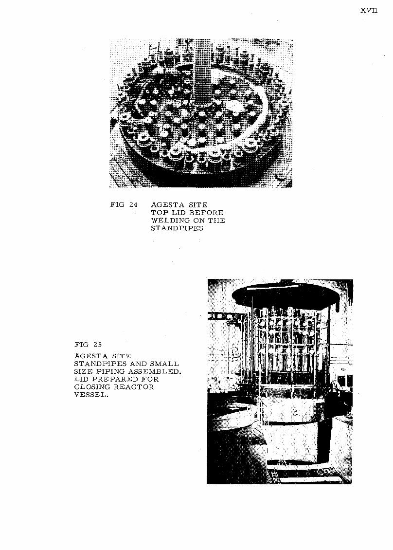
preheated for about six weeks. A view of the top cover after the tube
- 22 -
welding is shown in Fig, 24, The charging tubes and all small tubes for control and detecting applications were welded at site. The top cover after completing of this job is shown in Fig, 25, where the cover is just going to be placed on the tank portion of the vessel.
The inspection program was very extensive and covered at first
the steel production, plate rolling, casting, forging, tubing etc. before the vessel fabrication started. In this fabrication the inspection covered weld operator tests, weld procedure tests, X-ray and ultrasonic investigations and testing of steel coupons for control of the mechanical properties all the way through the fabrication.
It may be of some interest to mention a special investigation, which was made on welds representing the submerged arc type in the tank bottom, Fig. 27, and in the shell of the vessel, Fig. 26,
Fig. 27 shows some results from tensile and shear tests on material from a weld, representing the submerged arc welds in the bottom head. After welding the material has been normalized and stress relieved for a considerable time.
Both tensile and shear tests show that there is no significant difference between surface and centre of the plate material but that there are differences in the weld metal. The centre part of the weld has a somewhat higher analysis according to a greater proportion of base metal being melted and mixed with the weld metal. This gives the centre part of the weld about the same tensile and shear test values as the base metal. In the other parts of the weld these values are lower according to a weaker chemical analysis, but the tensile
test results still meet the UTS-specification of the plate material.

- 23 -
Fig, 26 shows some results from a similar weld that has been
stress relieved only. Here the normal harder peaks in the heat affected zones can be observed and the weld metal shows higher values
than in the previous case.
Interesting test material was received when eight discs were cut out in the tank bottom for the penetrations for the main nozzles for the
coolant. This material had under identical circumstances passed the
same operations as the tank bottom followed by the stress relieving treatment of the vessel, A very thorough investigation was carried out as to microstructure and mechanical properties of the base metal and the welded joints. The results confirmed those obtained by the pretests
and can be summarized in the following way,
a) The yield strength of the pressure vessel steel decreases slightly
after hot pressing,renormalizing and prolonged stress relieving but lies still within the specification.
b) The impact-transition curve for the pressure vessel steel shifts
to a slightly higher temperature by especially prolonged stress
relieving.c) Tensile specimens taken crosswise to the manual arc welded joint
showed a slight drop in the yield strength compared with the pretests but the values obtained were still within the specifications. Impact testing of the weld metal showed that this had kept its good impact properties.
d) Tensile specimens taken crosswise to the submerged arc welded joint did not show any difference in yield strength compared with
’ the pretests. The impact strength of this weld metal was, as the pretests had shown, inferior to that of the base metal and the manual arc weld metal, but still within the specification requirements.
Surplus material of the above mentioned type and origin is delivered to the customer - AB Atomenergi - who has prepared tensile and impact tests specimens, which will be put into the eleven tests

“ 24 -
specimen channels in the outer thermal shield of the rdactor. This material will give interesting information of the radiation damage effect
of the pressure vessel steel at. different intervals during the life time of the reactor.
Summary
The general desire by the power reactor process makers to increase power rating and their efforts to involve more advanced thermal
behaviour and fuel handling facilities within the reactor vessels are accompanied by an increase in both pressure vessel dimensions and various difficulties in giving practical solutions of design, materials and fabrication problems. In any section of this report it is emphasized
that difficulties and problems already met with will meet again in the future vessels but then in modified forms and in many cases more pertinent than before. As for the increase in geometrical size it can be
postulated that with use of better materials and adjusted fabrication methods the size problems can be taken proper care of. It seems likely that vessels of sufficient large diameter and height for the largest power output, which is judged as interesting in the next ten
year period, can be built without developing totally new site fabrication technique. It is, however, supposed that such a fabrication technique will be feasible though at higher specific costs for the same
quality requirements as obtained in shop fabrication.
By the postulated use of more efficient vessel material with principally the same good features of easy fabrication in different stages such as preparation, welding, heat treatment, etc, as ordinary or slightly modified carbon steels,the increase in wall thickness might be kept low. There exists, however, a development work to be
done for low-alloy steels to prove their justified use in large reactor pressure vessels. The problem of brittle fracture has haunted many technicians in various fields since it was first observed upon subjects of rather rough and undefined design and fabrication standard. The fact

- 25 -
that irradiation gives embrittling effects in vessel steels is in itself out of doubt. The question of what this rise of ductility transition temperature would really mean to vessels fabricated at the best
practice of manufacturing is still not answered today. The need for more accurate definition of what safety evaluation against brittle fracture should cover is obvious.
Another interesting problem complex is connected to the demand for higher process temperatures and more sophisticated design in local parts of the vessel. This will quite rapidly bring the aspects of creep and thermal fatigue within the complex of questions to be
dealt with.
Aside from these advanced aspects the interest in building reactor vessels at lower cost rates will give a full batch of problems even
if the prestanda of the vessel would not be required to increase physically. Although there may have been no total failures of reactor vessels
in service until now the serious situation is demonstrated by the fact
that during fabrication, inspection and assembly work threatening defects have been revealed. In some cases the observation was made as late as when the vessel was already assembled to circuitry piping
in the plant. The resulting time delay and additional money expenses have of course a tendency to give rise to unfavourable remarks upon the present aims of nuclear vessel technology. The true situation of nuclear vessel work of today might be stated so that all the way through each problem treatment involves the very best of an ever increasing quality standard practice completed with real extrapolations of the probability judgment of yet sparely clarified effects of various physical influences. As often will be the result from handling technical problems
this way the costs have a vivid tendency to go high. Many of the extra considerations in design and choice of structure materials, fabrication methods, quality control and pertinent inspection are no doubt justified
by the absolute need for safety against nuclear hazards during an economical vessel life time. It could, however, be suspected that the line

26 -
of conservative technical decisions in any problem is a bit unbalanced and not really giving that superior safety, which is justified to pay for. Thus selective studies of which factors in pressure vessel work do really inflict upon vessel safety are needed, so that technical decisions - code regulated or not - leading to specifically high costs without adding
any real or very small favour points in safety and long life vessel use could be eliminated or adequately ranged.
rn/el

FLOOR LEVEL OF

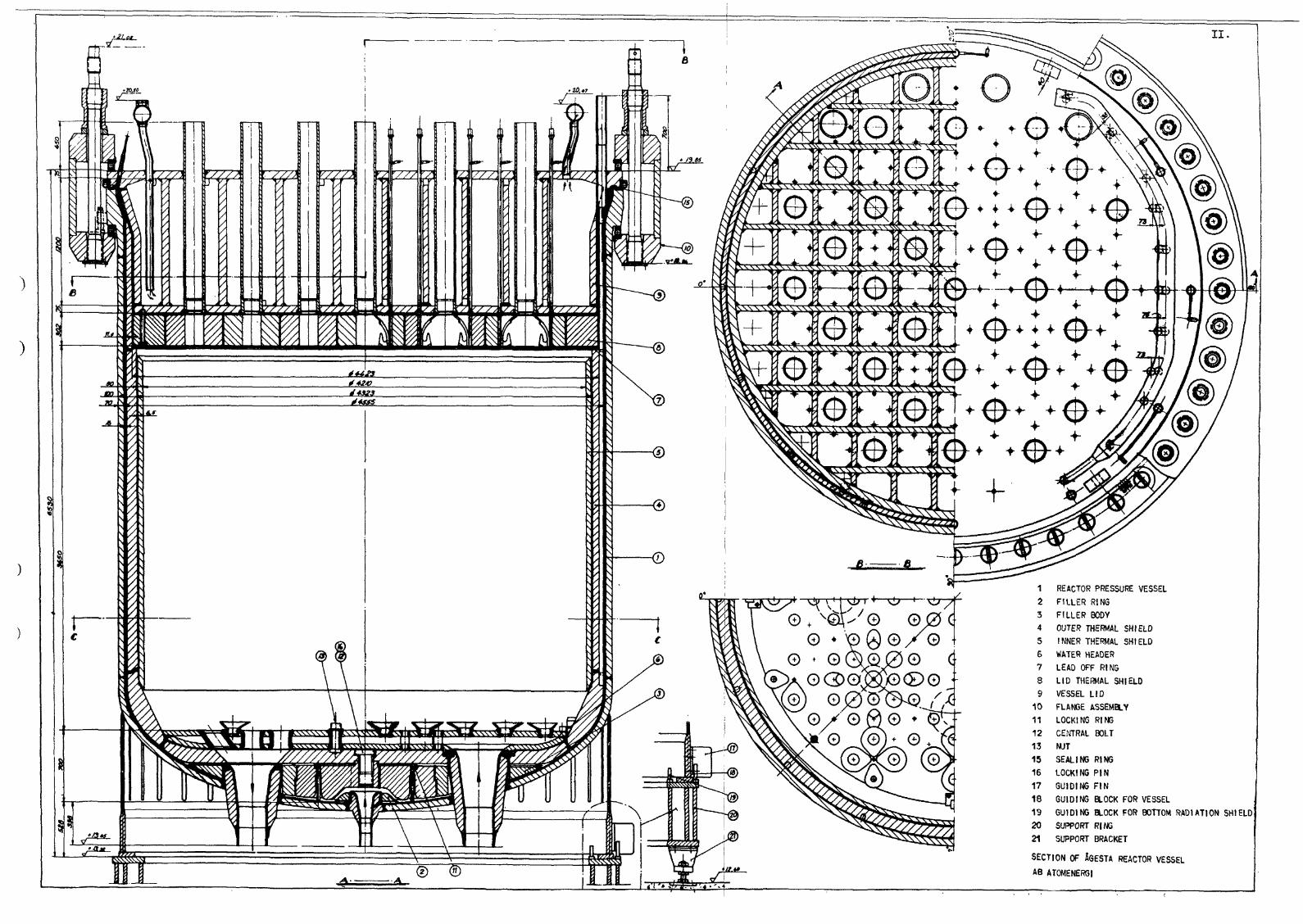
REACTOR PRESSURE VESSEL FILLER RING FILLER BODY OUTER THERMAL SHIELD INNER THERMAL SHIELD WATER HEADER LEAD OFF RING LID THERMAL SHIELD VESSEL LID FLANGE ASSEMBLY LOCKING RING CENTRAL BOLT NUTSEALING RING LOCKING PIN GUIDING FINGUIDING BLOCK FOR VESSEL GUIDING BLOCK FOR BOTTOM RADIATION SHIELD SUPPORT RING SUPPORT BRACKET
SECTION OF iGESTA REACTOR VESSEL
AB ATOMENERGI


Pressure Vessel with filler body
Agesta REACTOR VESSEL TANK DESIGN


AG
ESTA REA
CTO
R VESSEL
TOP LID D
ESIGN
Reactor Lid with
Upper Thermal Shield4 Pipes to pressurizer system
Loading stand
pipe with
control rod
Fuel
Canning Leak
detection
Outlet header for
Lid cooling system
Torus
Guide for Lid
thermal shield
Holding Bolt for
upper thermal shield
in Lid
Fuel Element
Loading Intake header for
Standpipe Bid cooling system
Inspection Tube
Fuel Canning Leak
Detection Tube
Reactor Vessel Wall
Outer thermal
shield


SECTIO
N O
F MA
RV
IKEN
BHW
R VESSE
L
SERVICE WITH BOILING WITH SUPERHEATING
SERVICE WITH BOILING WITHOUT SUPERHEATING


r~ V\ .\ \ \\ n \\\^X
>
0000060O O • o'# Q • ® • O O O'
0000000606 o: 000/oo#o#o#6#o#ooo 00^
49CS
o-e oO • Aj)
(D/#*o • o • o o q 0"0 0^0 o c
o-§22-
oQ
000
o • 00o ot?
0000 • o o'o o o \000#0»(J)#0
O oh 00000000, 0006000
000o o 0/
V,
VI.
reactor pressure vessel
radial thermal shield
(2) BOILER CHANNELS 151 OFF
SUPERHEATER CHANNELS 30 OFF
9 CONTROL RODS 30 OFF
# NEUTRON DETECTORS 9 OFF
© TRANSPORT CHANNEL FOR CONTROL RODS AND FUEL ELEMENTS 1 OFF
MARVIKEN BHWR LATTICE
AB ATOMENERGI


VII
COMPOUNDED IN 2 MM LAYERSOR 4 MM WELDED CLADDING
/rtcerl£L /
MARVTKEN BHWR SUPERHEATER NOZZLES IN
BOTTOM DOME. PROPOSED TEST MODEL DESIGN


I 1VIII.


Preliminary dimensions
PHWR-400 VESSEL WITH MODERATOR
TANK AND SHROUD HEAD


X
FIG 11 TEST MODEL OF FLAT TOP COVER AGESTA VESSEL
MODELVESSEL


XI
U00EH0LMS A B Carbon-Manganese-Steel Agesta
Degerfors Jarnverk2103-R3 Nuclear
Reactor
FIG 12CARBON-MANGANESE STEEL FOR AGESTA . VESSEL SPECIFICATION
Composition
C max. 0,16 11 7.
Si 0,15-0,5
Mn max. 1,6
P
§'
s " 0,03
Cr " 0,1
Ni » 0,1
Cl! " 0,1.
Co " 0,020 " (200 ppm)
N " 0,015
At C max. 0,15- Mn max. 1,7
» ii 0,14- || 1,8
Mechanical Properties
Yield Strength min 30 kp/mm (Lower yield point)
(a 30mm)
Ultimate TensileStrength 48-58 kp/mm
Elongationon 200mm min. 16 •/«
Impact Strength 2(Charpy-V.LS) min. 2,6 kpm/cm
(15 ftlbs) at -20*C
Heat Treatment. Normalising
PlQLe.jnGrid in the lid Upper plate in the lid Supporting ring in locking devise
Backing, material, _of clad _Steel_ plqte _i_n
Shell of the vessel Bottom head Shell of the lid Lower plate in the Ud
Forgings.Ln
Flange of the shell Flange of the lid Loose flanges Nozzles in the bottom head
Impact properties of 2103-R3 steel.Normalised material
kpm/cm Charpy-V specimens
Longitudinal---- 70mm clad steel plate---- Forging 500»320mm
Transverse
Temperature C
-140 -120 -100 -60 -60 -40 -20
FIG 13IMPACT QUALITIES OF THE AGESTA VESSEL STEEL UNIRRADIATED. (FOR IRRADIATION DOSE INTEGRATED- 2x10¹⁸ TRANSITION TEMPERATURE IS RISED LESS THAN 50° C).


XU.
Cylindrical shell thickness
Carbon-mangalese steeltable 2 note l)
= 30 kp/:
150 mm
100 mm .. Low-alloy steel table 2 note 2) and 3 o = 45-50 kp/mm
Low-alloy steel table 2 note 4) o =55 kp/mm^
50 mm ..
(Design pressure) x (inner diameter)
400 (b
f t fAGESTA marviken phwr-
PHWR BHWR -400
FIG 14 INFLUENCE OF STEEL QUALITY UPONWALL THICKNESS
BASHFUL-5 00


25 m --
20 m
15 m --
Agesta PHWR MARVIKEN BHWR
aHScale 1:200
FIG 15 SCHEMATIC STUDY IN SIZE
AB ATOMENERGI


departure from shop of
main parts of the
Agesta vessel
fig i6
FIG 17
SoWMY COMB GRID IN
WELDING POSITIONER
fig 18
IN TOP COVER. Agesta vessel
Mirror


XV
FIG 21
SUBMERGED ARC WELDING OF BOTTOM DOME TO THE CYLINDER SHELL


XVI
FIG 22 TEST ASSEMBLY OF FUEL ELEMENT FUNNELS INTO WATER DISTRIBUTION HEADER. AGESTA VESSEL

XVII
FIG 24 AGESTA SITETOP LID BEFORE WELDING ON THE STANDPIPES
FIG 25AGESTA SITE STANDPIPES AND SMALL SIZE PIPING ASSEMBLED. LID PREPARED FOR CLOSING REACTOR VESSEL.


XVIII.
Results trom shear tests on mikrospecimensfrom a submerged arc weld in plate of 2103-R3 quality.
FIG 26
MICROTESTING OF WELD AND TRANSITION ZONE MATERIAL STRESS RELIEVING ONLY
Shear strength kp/mm
Heat treatment after welding Stress relieving
Results from tensile and shear tests on mikro-specimens from o submerged arc weld in a100mm plate of 21Q3-R3 quality
FIG 27
MICROTESTING OF WELD AND TRANSITION ZONE MATERIAL NORMALIZING AND STRESS RELIEVING
UTS
Shear strength
kp/mm
Heat treatment after welding Normalizing and stress
relieving


LIST OF PUBLISHED AE-REPORTS
1—29. (See the back cover of earlier reports.)30. Metallograohic study of the isothermal transformation of beta phase in
zircaloy-2. By G. Ostberg. 1960. 47 p. Sw. cr. 6:—.31. Calculation of the reactivity equivalence of control rods in the second
charge of HBWR. By P. Weissglas. 1961. 21 p. Sw. cr. 6:—.32. Structure investigations of some beryllium materials. By I. Faldt and G.
Lagerberg. 1960. 15 p. Sw. cr. 6:—.33. An emergency dosimeter for neutrons. By J. Braun and R. Nilsson. 1960.
32 p. Sw. cr. 6:—.34. Theoretical calculation of the effect on lattice parameters of emptying
the coolant channels in a DzO-moderated and cooled natural uranium reactor. By P. Weisglas. 1960. 20 p. Sw. cr. 6:—.
35. The multigroup neutron diffusion equations/1 space, dimension. By S, Linde. 1960. 41 p. Sw. cr. 6:—.
36. Geochemical prospecting of a uraniferous bog deposit at Masugnsbyn, Northern Sweden. By G. Armands. 1961. 48 p. Sw. cr. 6:—.
37. Spectrophotometric determination of thorium in low grade minerals and ores. By A.-L, Arnfeft and I. Edmundsson. I960. 14 p. Sw. cr. 6:—.
38. Kinetics of pressurized water reactors with hot or cold moderators. ByO. Norinder. 1960. 24 p. Sw. cr. 6:—.
39. The dependence of the resonance on the Doppler effect. By J. Ros6n.1960. 19 p. Sw. cr. 6;—.
40. Measurements of the fast fission factor (s) in UOz-elemenls. By O. Ny- lund. 1961. Sw. cr. 6:—.
44. Hand monitor for simultaneous measurement of alpha and beta contamination. By I. O. Andersson, J. Braun and B. Soaerlund. 2nd rev. ed.1961. Sw. cr. 6:—.
45. Measurement of radioactivity in the human body. By 1. U. Andersson and I. Nilsson. 1961. 16 p. Sw. cr. 6i—.
46. The magnetisation of MnB and its variation with temperature. By N. Lundquist and H. P. Myers. 1960. 19 p. Sw. cr. 6:—.
47. An experimental study of the scattering of slow neutrons from HjO and D%0. By K. E. Larsson, S, Holmryd and X. Otnes. 1960. 29 p. Sw. cr. 6:—.
48. The resonance integral of thorium metal rods. By E. Hellstrand and J. Weitman. 1961. 32 p. Sw. cr. 6:—.
49. Pressure tube and pressure vessels reactors; certain comparisons. By P. H. Margen, P. E. Ahlstrom and B. Pershagen. 1961. 42 p. 5w. cr. 6:-—.
50. Phase transformations in a uranium-zirconium alloy containing 2 weight per cent zirconium. By G. Lagerberg. 1961. 39 p. Sw. cr. 6:—.
51. Activation analysis of aluminium. By D. Brune. 1961. 8 p. Sw. cr. 6:—.52. Thermo-technical data for D%0. By E. Axblom. 1961. 14 p. Sw .cr. 6:—.53. Neutron damage in steels containing small amounts of boron. By H. P.
Myers. 1961. 23 p. Sw. cr. 6:—.54. A chemical eight group separation method for routine use in gamma
spectrometric analysis. I. Ion exchange experiments. By K. Samsahl. 1961. 13 p. Sw. cr. o:—.
55. The Swedish zero power reactor RO. By Olof Landergdrd, Kaj Cavallin and Georg Jonsson. 1961. 31 p. Sw. cr. 6:—.
56. A chemical eight group separation method for routine use in gamma spectrometric analysis. II. Detailed analytical schema. By K. Samsahl. 18 p. 1961. Sw. cr. 6:—.
57. Heterogeneous two-group diffusion theory for a finite cylindrical reactor. By Alf Jonsson and Goran Noslund. 1961. 20 p. Sw. cr. 6:—.
58. Q-values for (n, p) and (n, a) reactions. By J. Koniin. 1961. 29 p. Sw. cr. 6:—.
59. Studies of the effective total and resonance absorption cross section for zircaloy 2 and zirconium. By E. Hellstrand, G. Lindahl and G. Lundgren. 1961. 26 p. Sw. cr. 6:—.
60. Determination of elements in normal and leukemic human whole blood by neutron activation analysis. By D. Brune, B. Frykberg, K. Samsahl and P. O. Wester. 1961. 16 p. Sw. cr. 6:—.
61. Comparative and absolute measurements of 11 inorganic constituents of 38 human tooth samples with gamma-ray spectrometry. By K. Samsahl and R. Soremark. 19 p. 1961. Sw. cr. 6:—.
62. A Monte Carlo sampling technique for multi-phonon processes. By Thure Hogberg. 10 p. 1961. Sw. cr. 6:—.
63. Numerical integration of the transport equation for infinite homogeneous media. By Rune Hdkansson. 1962. 15 p. Sw. cr. 6:-—.
64. Modified Sucksmith balances for ferromagnetic and paramagnetic measurements. By N. Lundquist and H. P. Myers. 1962. 9 p. Sw. cr. 6:—.
65. Irradiation effects in strain aged pressure vessel steel. By M. Grounes and H. P. Myers. 1962. 8 p. Sw. cr. 6:—.
66. Critical and exponential experiments on 19-rod clusters (R3-fue1) in heavy water. By R. Persson, C-E. Wikdahl and Z. Zadwdrski. 1962. 34 p. Sw. cr. 6:—.
67. On the calibration and accuracy of the Guinier camera for the determination of interplanar spacings. By M. MoIIer. 1962. 21 p. Sw. cr. 6:—.
68. Quantitative determination of pole figures with a texture goniometer by the reflection method. By M. MoIIer. 1962. 16 p. Sw. cr. 6:—.
69. An experimental study of pressure gradients for flow of boiling wafer in a vertical round duct. Part I. By K. M. Becker, G. Hernborg and M. Bode.1962. 46 p. Sw. cr. 6:—.
70. An experimental study of pressure gradients for flow of boiling water in a vertical round duct. Part II. By K.M. Becker, G. Hernborg and M. Bode. 1962. 32 p. Sw. cr. 6:—.
71. The space-, time- and energy-distribution of neutrons from a pulsed plane source. By A, Claesson. 1962. 16 p. Sw. cr. 6:—.
72. One-group perturbation theory applied to substitution measurements with void. By R. Persson. 1962. 21 p. Sw. cr. 6:—.
73. Conversion factors. By A. Amberntson and S-E. Larsson. 1962. 15 p. Sw. cr. 10:—.
74. Burnout conditions for flow of boiling water in vertical rod clusters. By Kurt M. Becker. 1962. 44 p. Sw. cr. 6:—.
75. Two-group current-equivalent parameters for control rod cells. Autocode programme CRCC. By O. Norinder and K. Nyman. 1962. 18 p« Sw. cr. 6:—.
76. On the electronic structure of MnB. By N. Lundquist. 1962, 16 p. Sw. cr6:—.
77. The resonance absorption of uranium metal and oxide. By E. Hellstrand and G. Lundgren. 1962. 17 p. Sw. cr. 6:—.
78. Half-life measurements of AHe, i*N, 1fO, z*F, #AI, nSem and 110Ag. By J. Konijn and S. Malmskog. 1962 . 34 p. Sw. cr. 6:—.
79. Progress report for period ending December 1961. Department for Reactor Physics. 1962. 53 p. Sw. cr. 6:—.
80. Investigation of the 800 keV peak in the gamma spectrum of Swedish Laplanders. By I. O. Andersson, I. Nilsson and K. Eckerstig. 1962. 8 p. Sw. cr. 6:—.
81. The resonance integral of niobium. By E. Hellstrand and G. Lundgren. 1962. 14 p. Sw. cr. 6:—.
82. Some chemical group separations of radioactive trace elements. By K. Samsahl. 1962. 18 p. Sw. cr. 6:—.
83. Void meosurement by the (y, n) reactions. By S. Z. Rouhani. 1962. 17 P. Sw. cr. 6:—.
84. Investigation of the pulse height distribution of boron trifluoride proportional counters. By I. O. Andersson and S. Malmskog. 1962. 16 p. Sw. cr. 6:—.
85. An experimental study of pressure gradients for flow of boiling water in vertical round ducts. (Part 3). By K. M. Becker, G. Hernborg and M. Bode. 1962. 29 p. Sw. cr. 6:—.
86. An experimental study of pressure gradients for flow of boiling water in vertical round ducts. (Part 4). By K. M. Becker, G. Hernborg and M. Bode. 1962. 19 p. Sw. cr. 6:—.
87. Measurements of burnout conditions for flow of boiling water in vertical round ducts. By K. M. Becker. 1962 . 38 p. Sw. cr. 6:*—.
88. Cross sections for neutron inelastic scattering and (n, 2n) processes. By M. Leimdorfer, E. Bock and L. Arkeryd. 1962. 225 p. Sw. cr. 10:—.
89. On the solution of the neutron transport equation. By S. Depken. 1962. 43 p. Sw. cr. 6:—.
90. Swedish studies on irradiation effects in structural materials. By M. Grounes and H. P. Myers. 1962. 11 p. Sw. cr. 6:—.
91. The energy variation of the sensitivity of a polyethylene moderated BF* proportional counter. By R. Fraki, M. Leimdorfer and S. Malmskog. 1962. 12 p. Sw. cr. 6:—.
92. The bockscattering of gamma radiation from plane concrete walls. ByM. Leimdorfer. 1962. 20 p. Sw. cr. 6:—. '
93. The bockscattering of gamma radiation from spherical concrete walls. By M. Leimdorfer. 1962. 16 p. Sw. cr. 6:—.
94. Multiple scattering of gamma radiation in a spherical concrete wall room. By M. Leimdorfer. 1962. 18 p. Sw. cr. 6:—.
95. The paramagnetism of Mn dissolved in # and ft brasses. By H. P. Myers and R. Westm.1962. 13 p. Sw. cr. 6:—.
96. Isomorfic substitutions of calcium by strontium in calcium hydroxyapatite. By H. Christensen. 1962. 9 p. Sw. cr. 6:—.
97. A fast time-to-pulse height converter. By O. Aspelund. 1962. 21 p. Sw. cr.6:—.
98. Neutron streaming in D;0 pipes. By J. Braun and K. Rand6n. 1962. 41 p. Sw. cr. 6:—.
99. The effective resonance integral of thorium oxide rods. By J. Weitman. 1962. 41 p. Sw. cr. 6:—.
100. Measurements of burnout conditions for flow of boiling water in vertical annuli. By K. M. Becker and G. Hernborg. 1962. 41 p. Sw. cr. 6:—.
101. Solid angle computations for a circular radiator and a circular detector. By J. Konijn and B. Tollander. 1963. 6 p, Sw. cr. 8:—.
102. A selective neutron detector in the keV region utilizing the MF(n, y)3BF reaction. By J. Konijn. 1963. 21 p. Sw. cr. 8:—.
103. Anion-exchange studies of radioactive trace elements in sulphuric acid solutions. By K. Samsahl. 1963. Sw. cr. 8:—.
104. Problems in pressure vessel. Design and manufacture. By O. Hellstrom and Ragnar Nilson. 1963. Sw. cr. 8:—.
Forteckning over publicerade AES-rapporter
1. Analys medeist gamma-spekfrometri. Av Dag Brune. 1961. 10 s. Kr 6z—<
2. Bestrdlningsforandringar och neutronatmosfar i reaktortrycktankar — ndgra synpunkter. Av M. Grounes. 1962. 33 s. Kr 6:—.
Additional copies available at the library of AB Atomenergi, Studsvik, Nyko- ping, Sweden. Transport microcards of the reports are obtainable through the International Documentation Center, Tumba, Sweden.
EOS-tryckerierna, Stockholm 1963