problems of face lighting. - politechnika Śląska
TRANSCRIPT

Problems of Face Lighting.
Without the least intention of detracting from the extremely useful technical nature of the paper which Prof. W. Cramp presented in Birmingham last month at a meeting of the Institute of Mining Engineers, it may be permissible to remark that its greatest value was revealed in its effective generation of a volume of criticisms and opinions of the utmost practical value in regard to face lighting in collieries. Which comment is, after all, another way of paying due tribute to the author of the paper.
Briefly the paper described an ingenious portable—or transferable—lighting system of which the unit consists of a number of small transformers with their primaries connected in series and spaced at intervals in a long length of flexible twin armoured cable. The primary with its half of the core is jointed permanently in the cable length: the secondary with the other half of the core is detachable and, in the form of a “ lamp fitting,” carries the lamp bulb and well-glass. The transformers are designed for constant current primaries and so that whether the core is complete (as with the lamp fitting in place) or incomplete (without the lamp fitting) the primary current, i.e. the current in the flexible cable, remains constant: furthermore should a lamp fitting be in place and the lamp fail, by open circuit or by short circuit, the transformer secondary current would still remain at its predetermined constant value. The suggestion was that a voltage of say 440 volts and a series of 21 transformer lamp fittings might be considered a suitable practicable unit. The author advanced a very attractive case and shewed by details that he had given his subject the most careful consideration from both the technical and practical usage points of view.
We have only given a general broad outline of Prof. Cramp's proposals but we believe it will serve to give the technical mining man a correct idea of the principles and motives involved. Let us now turn for a moment to the discussion and, in reviewing some of the. more prominent opinions which were expressed, hope to gain a further understanding of the paper itself and, above all, of the real perplexities of the mining men who have perforce to tackle this serious problem.
Referring to the suggested use of 440 volts, Dr. Allsop pointed out that the Mines Department did not sanction any pressure higher than 110 volts. The accidental severance of the cable or the breakage of a lighted lamp would introduce grave risks of gas ignition.
An interesting point was raised by Mr. Mitcheson, who in his experience had found that the filaments of 125 volt lamps were loo delicate and that the voltage drop was too much with 25 volt lamps; he, furthermore, wondered whether the hot 12 volt or 25 volt lamp filament was possibly more dangerous in gas than that of the 125 volt lamp. The mechanically stronger filament would lake longer to burn out in the event of the glass bulb being broken.
The cable proposed by Dr. Cramp would only be of 0.003 inch section whereas the present legal minimum for portable electrical apparatus is 0.022 inch, as was pointed out by Dr. W. Hancock. He presumed, however, that possibly a special permit could be obtained in regard to voltages anu conductor sections. Dr. Hancock also indicated the importance of arranging automatic leakage trips and circuit breakers so that a failure or fault on the lighting system should not jeopardise the continuity of the supplies to other electrical services at the face.
In view of the deep shadows and many obstructions to effective light distribution from fixed points, and in view of the complications introduced by a temporary, transportable, mains lighting system, Prof. W. 11. McMillan thought that to supplement the always necessary miners hand lamps or cap lamps with a number of portable high candle power lamps might be preferable to any mains system of installed lights.
The use of series interconnected lighting units did not appeal to Mr. H. 0. Dixon. Parallel connection of the transformer primaries introduced no technical difficulty; the parallel arrangement was much safer in the event of a fault on the mains, and the failure of one primary would not throw out of the whole of the lights as would happen with series interconnection.
The details of the proposed system and the questions involved in the whole subject of face lighting in general were admirably summarised in a written contribution by Mr. J” A. B. Horsley,H.M. Electrical Inspector of Mines. Mr. Horsley rivetted attention closely to the reasons why a concrete system of installed lighting is necessary for modern face working. Hand lamps were for an individual man working : power plant and mechanised working demanded general illumination. The many open-lamp pits, as in Scotland where they are also fully mechanised, should be freely used for trying-out face lighting systems; there their efficacy, costs, durability, etc. could be proved without dangerous risk. Mr. Horsley believed that lights in series on 500 volt mains, or any pressure nearly so high, could be ruled
302 THE MINING ELECTRICAL ENGINEER. March, 1932.
out: he was inclined to consider that the best all round results would be gained by using a pressure not higher than 12 volts. Mr. Horsley could nol see any advantage in the series system and its elaboration to keep the lamp voltage constant: he believed that the normal fluctuations in voltage of the power system, from which the lighting service was drawn, would in effect be the factor controlling the lamp voltage. Realising the force of the contention that fixed lighting points were under certain conditions of working likely to be unsuitable, Mr. Horsley indicated that it was easily ossible to arrange for the lamp bulb fitting to e carried on a short flexible lead. Another im
portant point was the doubt as to whether it would be practicable in the mine to handle about 100 yards of armoured flexible cable with 20 or so awkward and heavy fittings fixed permanently at intervals along its length.
There were many other criticisms by various speakers and contributors, favourable and adverse, than the few we have mentioned. Those selected here will, however, serve to emphasise the fact that the problem of face lighting is far from being solved. The technical side of the matter may be sufficiently well understood, but there is a great deal of work yet to be done in the trial of full size installations in actual service in the mine. The decision of the Mines Department to defer for at least twelve months any steps towards formulating new official mines lighting rules and regulations—and restrictions—was a wise one. Particularly must credit be given to
Dr. Cramp in that he has by his paper been the means of compelling attention to the urgent necessity of engineers, managers and inspectors coming into the closest collaboration for devising and proving satisfactory ways and means of illuminating the underground workings of the modern machine-run colliery.
A.M.E.E. Annual Convention:
1932.This year the Summer Convention and Annual
General Meeting of the Association of Mining Electrical Engineers will take place in Scotland. The preliminary programme of tne round of events extending from the 20th to the 24th of June is published in this number, in the A.M.E.E. Official Notices columns, and it shews that the arrangements are already so far planned as to ensure a notably interesting and enjoyable sequence of tours and ceremonies. Those fortunate people who attended the last Scottish Convention held in Glasgow in 1923 will not require any persuading to book early.
We would advise members of the Association to refer back for a moment to our issue of July 1923 and remember that it is now the great effort of their Scottish colleagues to make certain that this year's convention shall surpass even the wonderful success they attained on the last occasion.
SAFETY CONFERENCE FOR BIRMINGHAM.
Mr. Isaac Foot, M.P., Secretary for Mines, announces that a General Conference on Safety in Mines, representative of all those engaged in the coal mining industry in the Midland and Southern Inspection Division and North Staffordshire, will be held under his Chairmanship at Birmingham, on Saturday, the 30th April, 1932, from 11-0 a.m. to 5-0 p.m. Addresses will be given by Sir Henry Walker. C.B.E., LL.D., H.M. Chief Inspector of Mines: Mr. W. E. T. Hartley, H.M. Divisional Inspector of Mines: Professor R. V'. Wheeler. D.Sc., Director of the Research Stations under the Safety in Mines Research Board; and Major H. M. Hudspeth, D.S.O., M.C., M.Sc.. Mining Engineer to the Safety in Mines Research Board. The addresses will be followed by questions and discussion which will be confined to matters affecting safety. A detailed announcement will be made in due course.
NEW ADDRESS.
The Secretary for Mines announces that as from 11th March, the office of Mr. T. Ashley, H.M. Divisional Inspector of Mines for the Swansea Division will be the 2nd Floor, Dryslwyn House, De la Beche Street, Swansea. The telegraphic address and telephone number will remain unaltered, viz.:— “ Mines Inspector, Swansea,” andSwansea 2367. After normal office hours urgent messages should be addressed to Mr. Ashley at his private residence, “ Moorside,” the Mayals, Blackpill, Swansea (Telephone Number. Mumbles 6451).
THE RENOLD AND COVENTRY CHAIN Co. Ltd.
It is announced that as from March 14th the businesses formerly carried on by—Hans Renold Limited, at the Renold Works. Didsbury, Manchester: and TheCoventry Chain Company Limited, at the Coventry Chain Works, Spon End, Coventry; will be taken over by the Renold and Coventry Chain Co. Ltd.. which will conduct its trading operations from the same addresses as the previous companies. Enquiries, orders and all communications concerning “ Renold,” “ The Coventry,” and
“ Brampton ” products should, therefore, continue to be sent to Manchester or Coventry or to any of the Branch Offices as best suits the convenience of the customers.
ELECTRICAL SHOT-FIRING.
The Explosives in Coal Mines (Electrical Shot-Firing Apparatus) Order, 1932. H.M. Stationery Office; Id. net.) stipulates:
(a) After March 31st every new exploder taken into use in any mine or part of a mine in which permitted explosives are compulsory must be of a type that has been approved by the Board of Trade. Exploders not of approved types now in use in such mines must be replaced by exploders of approved types not later than December 31st next.
(b) The exclusive use of magneto exploders is no longer required; battery and dynamo exploders will be approved if they pass the official tests.
(c) Provisions are included for guarding against exploders being rendered unsafe by unauthorised interference, and for periodical examination and efficient maintenance of approved exploders.
Apparatus approved by the Board of Trade under this Order includes the Davis No. 15X (1932) low-tension exploder and No. IX (1932) high-tension exploder for single shots, both manufactured bv Messrs. John Davis S Son (Derby) Ltd.
These approved exploders are fitted in pressed-metal cases, having tightly-fitting pressed-metal tops, so that they cannot be affected by moisture or excessive dryness and, being pressings, they are not liable to become dented and the gearing damaged. All small parts, where possible, have been eliminated and embodied in one unit. For instance, the key socket hitherto held in position by screws now forms part of the lid. Another important feature of these exploders is that they are locked by means of triangular-shrouded screws which can only be operated by means of a special key, which is in charge of the electrician or some other authorised person. To tire a shot a sharp half-turn of the hand only is required, when contact is made and broken automatically at the end of the stroke.

March, 1932. THE MINING ELECTRICAL ENGINEER. 303
Proceedings of the Association of Mining Electrical
Engineers.
NORTH OF ENGLAND BRANCH.
Alternating Current Motors for Collieries.A. T. ROBERTSON.
(iContinued from page 282).
Types oi Windings.
There are two main types of windings, namely, concentric and basket; and each type has variations. Broadly, the concentric type, shewn in Fig. 18, is used for stators, because each slot accommodates only one coil side, and therefore there is only a very small voltage between the conductors in any slot. Further, the end windings are easy to insulate, and give good, natural cooling; and the connections are easy to check. Thediamond coil basket type, shewn in Fig. 19. is usedfor rotors, because it forms a smooth ring of end windings capable of being bound tightly against centrifugal force, and all coils are formed alike. When the basket type is used on stators, it is usually because it is desiredto take advantage of the fact that the coils can be shortpitched. Fig. 20 shews a cross-breed winding, known as the mush type, which has some of the advantages of both the others. All coils are alike, they form a continuous band of end winding, and each slot accommodatesonly one coil side. Unfortunately, it is only suitable for small wires, and so for small machines; and, further, the end windings lie close together, which means that the insulation needs reinforcing between phases, and the natural cooling is not, perhaps, quite so good as with the concentric type.
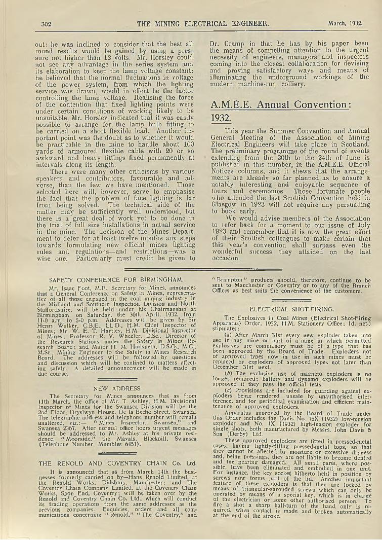
Fig. 21 shews a high voltage stator with a concentric type winding, which should always be used forhigh voltage, because it allows adequate insulation of the
Fig. 19.
end windings. The coils should be formed, impregnated, and moulded with mica along the slot portion, before being fitted into the stator. Open slots enable this to be done without a joint at each turn. This construction makes it easy to replace a coil, or even to rewind on site; but open slots tend to reduce both power factor and efficiency, and allowance for this must be made in the design.
For stators with the semi-closed slots used on medium voltage machines, there are three methods of winding, each having its particular applications:
(1) “ Drop in ” through the mouth of the slot; suitable for powers for which the size of the conductor may be smaller than the mouth of the slot.
(2) “ Pull through” using a stranded conductor when necessary for easy bending by hand; suitable for powers for which there are not more than about 10 conductors per slot.
(3) “ Hairpin ” coils, pushed through from one end, and having joints made between the turns after the coil has been fitted and the second end winding formed;
fig . 18. Fig. 20.
304 THE MINING ELECTRICAL ENGINEER. March, 1932.
Fig. 21.
suitable for machines lying between the sizes of (1) and (2), but to be looked upon as not good practice, on account of the number of joints.
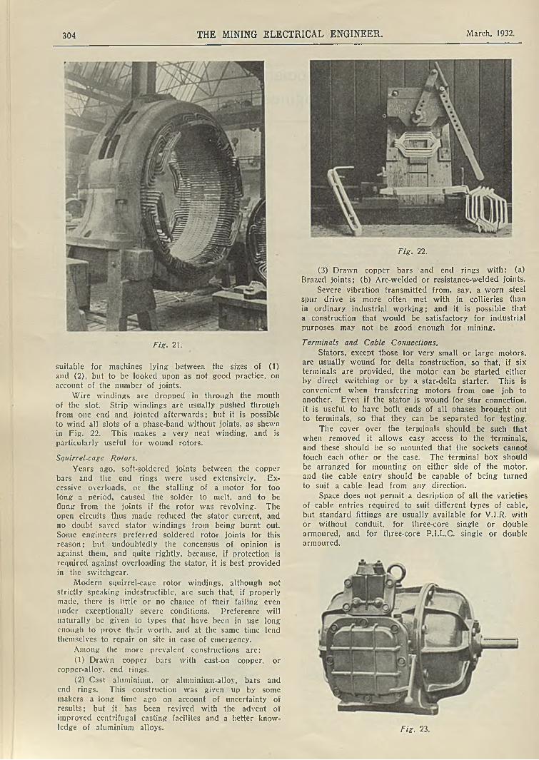
Wire windings are dropped in through the mouth of the slot. Strip windings are usually pushed through from one end and jointed afterwards; but it is possible to wind all slots of a phase-band without joints, as shewn in Fig. 22. This makes a very neat winding, and is particularly useful for wound rotors.
Squirrel-cagc Rotors.
Years ago, soft-soldered joints between the copper bars and the end rings were used extensively. Excessive overloads, or the stalling of a motor for too long a period, caused the solder to melt, and to be flung from the joints if the rotor was revolving. The open circuits thus made reduced the stator current, and no doubt saved stator windings from being burnt out. Sonie engineers preferred soldered rotor joints for this reason; but undoubtedly the concensus of opinion is against them, and quite rightly, because, if protection is required against overloading the stator, it is best provided in the switchgear.
Modern squirrel-cage rotor windings, although not strictly speaking indestructible, are such that, if properly made, there is little or no chance of their failing even under exceptionally severe conditions. Preference will naturally be given to types that have been in use long enough to prove their worth, and at the same time lend themselves to repair on site in case of emergency.
Among the more prevalent constructions are:
(1) Drawn copper bars with cast-on copper, or copper-alloy, end rings.
(2) Cast aluminium, or aluminium-allov, bars and end rings. This construction was given up by some makers a long time ago on account of uncertainty of results; but it has been revived with the advent of improved centrifugal casting facilites and a better knowledge of aluminium alloys.
Fig. 22.
(3) Drawn copper bars and end rings with: (a)Brazed joints; (b) Arc-welded or resistance-welded joints.
Severe vibration transmitted from, say, a worn steelspur drive is more often met with in collieries thanin ordinary industrial working; and it is possible that a construction that would be satisfactory for industrial purposes may not be good enough for mining.
Terminals and Cable Connections.
Stators, except those for very small or large motors, are usually wound for delta construction, so that, if six terminals are provided, the motor can be started either by direct switching or by a star-delta starter. This is convenient when transferring motors from one job to another. Even if the stator is wound for star connection, it is useful to have both ends of all phases brought out to terminals, so that they can be separated for testing.
The cover over the terminals should be such that when removed it allows easy access to the terminals, and these should be so mounted that the sockets cannot touch each other or the case. The terminal box should be arranged for mounting on either side of the motor,
and the cable entry should be capable of being turnedto suit a cable lead from any direction.
Space does not permit a desription of all the varieties of cable entries required to suit different types of cable, but standard fittings are usually available for V.I.R. with or without conduit, for three-core single or double armoured, and for three-core P.I.L.C. single or double armoured.
Fie. 23.

March. 1932. THE MINING ELECTRICAL ENGINEER. 305
Constructions to meet Special Needs.
Flame-proof enclosure to meet the requirements of the Coal Mines Act, where Regulations 127(v) and 132 apply, is necessary on external sliprings, on motors having a commutator or internal sliprings and on every induction motor for portable or semi-portable machines. This means, briefly, that coal face machinery motors must have a complete flame-proof enclosure, whereas only the sliprings require a flame-proof enclosure in motors permanently fixed in positions where there is only a very remote possibility of an explosive atmosphere. Fig. 23 shews a flame-proof motor with a flame-proof switch and dividing box.
To ensure flame-proof enclosure, special precautions are required at all joints, as well as where the shaft and leads to the terminals pass through the enclosure. The terminal box itself should be explosion proof, and so should the motor, whether or not the terminal box is in position. All the enclosures should be strong enough to withstand easily the mechanical stress due to the most violent explosion, namely, about 120 pounds per square inch. A great deal of useful work has been done by the Safety in Mines Research Board on the problem of flame-proof enclosure, and their reports,
together with British Standard Specifications Nos. 229 and 270, are extremely useful to anyone interested in the subject.
Special care should be taken that ordinary totally- enclosed motors are not inadvertently transferred to positions apt to become explosive. They may look innocuous; but if they happen to be situated in a pocket of stagnant air they are probably more likely than a ventilated motor to accumulate an explosive mixture; and if this is exploded the motor may burst, with decidedly unpleasant consequences for anyone near, even if the outside atmosphere is at the time non-fiery.
Coalcutter and Conveyor Motors.
The arduous duties of coalcutter and conveyor motors, together with the exceptional conditions under which they have to work, renders special construction imperative to ensure useful service. Being part of the coalcutter or conveyor head, they should be shaped to fit snugly in position, and should be secured by substantial fixings. The rugged frame enclosure common to all mining motors is necessary if they are to withstand heavy falls and rough handling; and usually the conditions in the mine are such that the enclosure must also be flame-proof. Fig. 24 shews a half-section view of a recently developed conveyor motor and its special cradle. The exceptionally severe duty and working conditions of such motors tend to make failures more prevalent than would be tolerated
with ordinary motors, and so ease of handling and of repair and replacement of damaged parts is essential.
A flame-proof plug and socket made to British Standard Specification No. 279 should be used for the flexible connection to a coalcutter motor. For conveyors, seeing that they are semi-portable machines, it is convenient, though not compulsory under the Coal Mines Act, tohave same form of flame-proof connector in preference to the usual terminals and trifurcating box. This connector may be bolted in position, and need not beinterlocked with the control switch. The fixing should be so arranged that there is no projection likely to be damaged when the motor is being taken in-bye.
Fig. 25 shews a flame-proof coal-drill. complete with handle switch and plug and socket. There are numerous other special constructions of interest, but on an occasion like this it is impossible to refer to them all, and those that have been mentioned are perhaps the most important for the present purpose.
Fig. 24.
APPENDIX.
The Circle Diagram in Simple Form.
A circle diagram, such as is shewn in Fig. 26, enables the performance of any induction motor to be visualised and determined without troubling about the theory of its operation. It is a diagram, not a graph, and it shews the locus of the stator current as it increases from no-load through its whole series of values up to standstill. It can be drawn for any induction motor when three particular constants of the motor are known; and these are easily obtained by test, or from the manufacturen. They are: (1) The no-load current and watts; (2) Theshort circuit current and watts; (3) The short circuit stator copper loss = 3 (short circuit current per phase)2
X (resistance per phase).
From the circle diagram it is possible to scale off, without calculation: the input; the rotor current; the power factor; the torque; the output; the efficiency; and the speed, corresponding to any stator current.
Also the starting torque; the maximum torque; the maximum horse-power; and the maximum power factor that can be obtained. The effect of external rotor resistance on the starting torque and on the speed are also
obtainable. It is, in fact, possible to obtain information about everything but why the motor will not start if
something has gone wrong !
To draw the diagram, first choose a scale of current that suits the size of paper used. If this is, say 10 amperes per inch, then, since 1 in. = 10 amperes, it is possible to determine the values per inch of other variables. Thus, if the voltage is V, 1 in. in watts is 10f3V; and if V is, say 430 volts, 1 in. = 7400 watts.
Fig. 25.

306 THE MINING ELECTRICAL ENGINEER. March, 1932.
AT ANY POINT ON THE CIRCLE. A t p o i n t © ON THE CIRCLE.
S t a t o r C u r r e n t — S , “ 2l"x 10 - 21 A .
In p u t = I. « 1*6* x 7460. - 12 kW.
r o t o r Cu r r e n t ~ R . x Tr. r atio . « I-5V 10 « is a x T r .r a t io .
p o w e r -F a c t o r =Cos $ *$■ -• 7 7
TORQUE » T . “ K'x.52-5 -7 S -S L 8 . -F T ;
Ou t p u t - R - 1-3’x 10 * 13 ne
E f f i c i e n c y - - f - % ■ « ’81 OR 81%
SPEED X S y n .R.RM. -'■ % V x lO O O “ 930 R.PM.
5CALE : r - 10 AMPERES * 7,460 W ATT5 AT 430 VOLTS - 10 HORSE-POWER - 52-5 TOUND5-FEET AT 1000 R-RM,
Fig. 26.
Hence 1 in. = also 10 h.p. for the numerical values chosen, since 1 h.p. is 746 watts. Further, since horsepower X 5250 = torque in pounds-feet X speed in r.p.m. 1 in. = 52,5 pounds-feet if the synchronous speed is
1000 r.p.m. To summarise:
1 in. = 10 amperes.1 in. = 7460 watts.1 in. = 10 h.p.1 in. = 52.5 Ib.-ft.
Point (1) on the diagram is the intersection of a circle of radius = no-load current and a horizontal line at a height above the base = no-load watts; point (2) is a similar intersection for short circuit current and watts; and for point (3) draw a vertical line through point (2) and measure up it from the base a distance equal to the sum of the short circuit stator copper loss and the no-load watts. The diagram is completed by drawinga circle passing through points (1) and (2) with its centre on a level with (1), and by joining (1) and(2) to the origin O and (2) and (3) to (1). Then, for any point (X) on the circle, values of S, I, R, T, and P can be scaled off, and so the performance isdetermined. Complete performance curves can be drawn by taking a series of points round the circle.
The same diagram also represents the behaviour of the motor when stalled, with the rotor connected to an external variable resistance. Point (1) then corres
ponds to open circuit or infinite external resistance, and point (2) to short circuit or zero external resistance. Everything remains as before except P, which now represents the loss in watts in the external resistanceinstead of the power from the shaft. In the examplechosen, the maximum torque will be obtained for starting if the external resistance is about H times the rotor resistance.
LONDON BRANCH.
Insulator Reliability in Service.
R. C. ANDERSEN.
(Paper read 5th January, 1932).
Insulator depreciation in service is a very serious phenomenon of which little to date is known in this country owing to the fact that most of our overhead network represents post-war construction completed within the last decade. Three other factors account as well for our apparent immunity from
insualtor trouble. They are:—
1. The relatively small and completely self-contained characteristic of our erstwhile most important overhead
power systems.
2. The relatively light electrical and therefore mechanical loadings on these systems.
3. Our climate which, from the insulator point of view, leaves little to be desired.
With the development of our National Grid and the inevitable interconnection thereby of all adjacent systems; factors 1 and 2 will automatically cease to operate in our favour. It will then be increasingly evident just how
far British insulator technique in eliminating depreciation has advanced. It is sincerely to be hoped from every point of view, but more especially from the financial, that the depreciation we suffer will be as low as we have a right to expect.
DESCRIPTION OF INSULATOR DEPRECIATION.
What is insulator depreciation ? That is a question the writer has often had put to him. Seeing that insulator reliability in service may be taken to vary inversely as insulator depreciation, it would seem well
worth while shortly to answer the query.
Although porcelain is universally accepted to be the very best product wherewith to manufacture line insulators, nevertheless it has very severe limitations.
Firstly, in the making, it requires to undergo aseries of very complex processes, through every oneof which extraordinary care must be exercised to ensure sound ware.
Secondly, when made, it is crystalline in structure and therefore subject to the weaknesses of all such similar substances.
Thirdly, though very strong in compression it is relatively weak in shear.
Lastly, it has a modulus of elasticity and a coefficient of expansion much less than either cement and malleable cast iron or steel—three materials with which it is inevitably associated in line insulators.
Unless therefore these fundamental physical characteristics of porcelain, M.C.I. and/or steel, are intelligently harmonised in the assembled insulator, the porcelain will crack in service. The crack in time will wander through the body, very materially lowering its dielectric

March, 1932. THE MINING ELECTRICAL ENGINEER. 307
>-wt //y SCY/Ci
n e e -/ -v s t/ iX T O J ? a r c c v m j t s
i - p v V fe r- / / t o r n /*t /y//y
■x-//y r o v r s T c c
Fig. 2.
strength, and then on the slightest provocation—even under a normal switching surge—the insulator will puncture. When this occurs, the insulator is said to be depreciated.
Every operating engineer’s experience encompasses punctures of insulators. Initially the punctures are classified as “ mysterious” and vaguely attributed to.lightning. But with increasing experience Supply Companies’ officials are not slow to discern:—
(a) That these punctures on a given line may increase progressively with time.
(b) That they are associated with specific insulator assemblies.
(c) That they are in no way associated with insulator rating. In other words, that a larger insulator for a given voltage does not imply a lowering of the puncture risk.
(d) That the puncture may or may not visibly damage either the main insulator body or its sheds or, in the case of the suspension insulator, its flange.
Fig. No. 1, which the author is enabled to reproduce thanks to the courtesy of Messrs. G. H. Swingler and W. de Smidt, who incorporated it in a very valuable paper presented by them before the South African Institute of Electrical Engineers, shews eleven insulatorsthat punctured on their system after but four months’ operation. All these insulators punctured from the underside of the top petticoat to the pin, yet it will be observed that whilst three insulators remained absolutely intact all the others had their top sheds blown off.
Fig. No. 2 shews a 7 ins. dia. cap and pin suspension insulator with a neat hole drilled by the puncturing arc right through the cap. Here again theinsulator is superficially intact.
It has been indicated that time is an importantfactor in insulator depreciation. Clearly, this must beso, for it takes time for cracks to wander through the dielectric. This explains why almost all modern insulators function quite efficiently—dependent on good or bad climatic conditions—for a longer or shorter period.
Figs. 3, 4, and 5 are records of insulator depreciation on systems as far remote one from the other as Sweden, Canada and California.
The author is indebted to Mr. Valander for Record No. 1. Despite the differences in geographical situation of these systems, the general form of the curves
Coltatioo oli&culatori tetnoired Itoro 33 kV line between Capetown and ob « h u h 11 ia«ula.t«ritailed «¿this 24 hoon. All the instilfelots were punctured Irorn the ui»Jer*MSe ol the top petticoat to tbe
pm : most o! them had :be top abed completely blot* q oil.
Fig. 3.
J i Q 7 £ : C u r y f t rfrjrgw/V</ ¿ y j
S + //rr j- A r * f v t x / u c / l o f M e XHrrre
& 3_/s/4 /3/c /s/e /seo /see
FIs- 1. Fig. 4. and Fig. 5.

308 THE MINING ELECTRICAL ENGINEER. March, 1932.
for the porcelain to be subjected to a thermal stressof 700 to 900 lbs. per sq. inch. When to this is added normal loading stresses, it no longer appears fantastic to contend that under all conditions of service, very many suspension insulators installed to-day do not have as high a factor of safety as 2, despite what laboratory tests may lead one to conclude. In point of fact, it requires many refinements to be embodied in a suspension insulator to reach the factor of safety of 2 mentioned.
Fig. 6A shews a method of grooving porcelain for
cement keying purposes. Figs. 6B and 6C shew variations of this grooving. All three methods have been
extensively used; yet it is safe to say that no betterway of maltreating porcelain could very well be devised. Not only is the porcelain structure weakened by these indentations (much the same as the weakening
of a pane of glass by scratching it, say, with a diamond) but the form of these indentations is such as inevitably to lead to concentrated stresses in the porcclain due to cement expansion. Rapid insulator cracking or deprecia
tion then is only a matter of time.
Revert to Fig. 1, and note that the porcelain surfaces are grooved. May that not be one of the major causes
of the trouble experienced ? Admittedly most of the insulators assembled in this manner have the grooves treated with some form of compound for which resiliency is claimed. The addition of this compound al
leviates matters only slightly for not only is a portion of the compound absorbed by cement during assembly, but the combination makes absolutely no provision for
the development of hard spots in the cement due to slight chemical changes, which are likely to occur therein with time.
Now there are many examples in our ordinary
workaday world, of sensitive structures equipped withvarious devices, not only to safeguard them from severe mechanical shock but also to ensure that, if they are subjected to consistently heavy loads, the effect of these loads will be spread over large areas and thereby dis
sipated harmlessly through the structure. Such comprise for instance shock absorbers, balloon tyres, spring mattresses, the end bearings of vertical turbo-alternators,
Fig. 6a. Fig. 6b.
is very similar in that the “ no-trouble ” or immunity period, except in the case of curve B2. Fig. 4, is approximately 4 to 5 years. Curve B2 rivets attention; for
it clearly demonstrates that insulators can be manufactured to give a well-nigh perfect service. Incidentally it is a record pertaining to many thousands of insulators of one specific design.
Fig. 6 c.
MECHANISM OF INSULATOR DEPRECIATION.
A harmonious assembly of porcelain, cement and metal has been postulated for successful insulator operation: but what exactly may this statement imply? Briefly, the root of the matter is this: cement and metal both have coefficients of linear expansion, which are very approximately twice that of porcelain. Hence, when an insulator is either contracting due to a fall in temperature, or expanding due to temperature rise, the porcelain is subjected to unbalanced stresses which, since they are directly associated with temperature change, are called thermal stresses. These stresses assume proportions far greater than is generally believed. For instance in an orthodox 10 ins. suspension insulator, it is not unusual
Fig, 7.Fig. 8.

March. 1932. THE MINING ELECTRICAL ENGINEER. 309
SOO JSO 400 *60 / W *
¿■•4S % D i p r t r i j f i o r t
etc elc. Examples are legion. It was similarly anil logically to protect porcelain surfaces to be cemented that Mr. A. C. Austin of the Ohio Brass Company devised the sanded surface. Fig. 7 shews a micro- pliotograph of this development. It comprises the adhesion to plain, and therefore strong, porcelain walls of numberless small porcelain granules. On a hard spot developing in the cement the granule or granules in the immediate vicinity crush slightly and the stress is at once spread over a number of adjacent granules. The safeguarding of the porcelain is obvious.
It did not take long for Mr. Austin to perceive that the sanded surface was only a relatively good panacea for insulator depreciation, however much it was an improvement on grooved or scored porcelain. His next step therefore was to treat the sanded surface, and Fig. 8 shews this advance. Surrounded by a resilient medium the granules now take up the characteristics of light flexible springs and because of this characteristic multipart pin and post insulators in particular have experienced surprisingly low depreciation over a term of years.
The author recently had a remarkable demonstration of this fact. Some hundreds of grooved insulators were supplied and erected simultaneously with approximately the same number of treated sanded units in one of our tropical dependencies, where striking temperature changes arc of daily occurrence and humidities are very high every evening. After 27 months’ operation, the grooved insulators shewed a depreciation varying from 9“° to 46°/o 011 various parts of the system; whereas not a single cracked insulator could be discovered amongst the refined assemblies. Here we have a signal instance of the effect of climate as represented by thermal stresses on insulator life. A depreciation of 46°/b in a little over two years, is astounding; and as a matter of interest Fig. 9 shews the depreciation curve alongside that of Velander’s in Fig. 3. The financial losses due to interruptions were naturally very high.
Fig. No. 10 is a valuable record of the effect of varying climatic conditions 011 insulator depreciation. The line in question was erected on 650 supports and it was located in South Sweden. It will be observed how very much greater the depreciation was in flat open country, due to the thermal stresses associated with the salt deposits to which this section of the line was subjected.
r / j S f y £ A J P S ' / / V S U l/ t T O & 77o r v O/v j ¿ / / Y / r //V
Fig. 10.
PIN INSULATORS.
No reference has yet been made to pin insulatorshape; but a rapid analysis will immediately demonstrate that a correct configuration is fundamental to insulator reliability in service. Expressed another way, the heating to which an insulator is subjected derives directly from its shape. If this is incorrect severe local heating will occur and this in turn will give rise to high thermal stressing and consequent failure bycracking and puncture. Fig. 11 shews typical pin insulator failures of the type to which reference lias been made.
It is well established that deposits on insulatorscause excessive heating; but it does not seem to be as readily appreciated that a correctly designed insulator will suffer much less deposit than one which, in an effort to enhance leakage distance or tlashover or some other specific characteristic, runs counter to the law of electrostatic balance as applied to insulators.
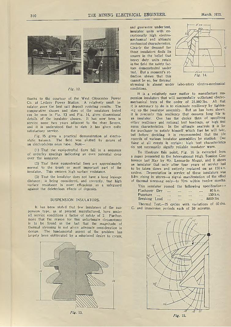
Fig. 12 is a valuable demonstration of the point under review. It shews a salt test being carried outon a series of insulators of different shapes and sizes, with full load applied. The tests were carried out,
310 THE MINING ELECTRICAL ENGINEER. March, 1932.
and guarantee under test, insulator units with exceptionally high electromechanical and ultimate mechanical characteristics.Clearly the demand forthese insulators finds its source in the belief that heavy duty units retainin the field the safety factors demonstrated under test. But a moment’s reflection shews that this cannot be so, for thermal stressing is absent under laboratory electro-mechanical
conditions.
It is a relatively easy matter to manufacture sus
pension insulators that will successfully withstand electromechanical tests of the order of 25,000 lbs. All that it is necessary to do is to eliminate resiliency by tightening up the insulator assembly. But as has been shewn, it is precisely this resiliency that ensures long life to an insulator. One has the choice then of specifying
either resiliency and rational test loadings, or high test room characteristics. In the ultimate analysis it is for the purchaser to satisfy himself which line he will take, but before deciding it is recommended that the liferecords of various insulator assemblies be studied. One thing at all events is certain: high test characteristics
do not necessarily signify reliable insulator ware.
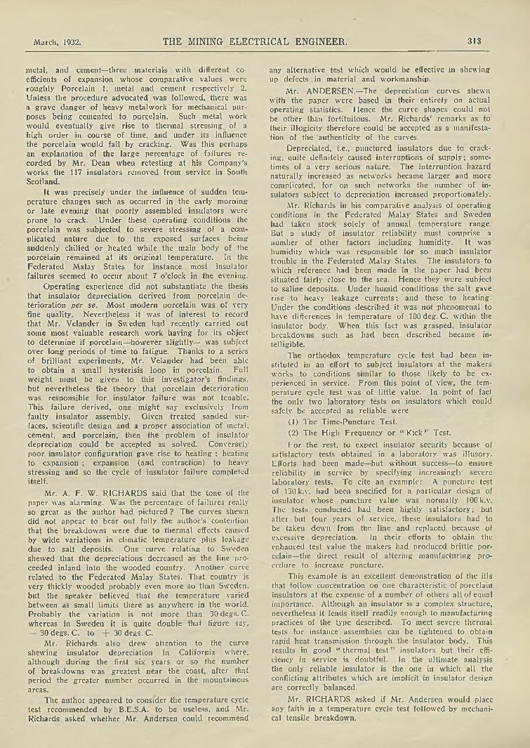
To illustrate this point, Fig. 16 is extracted from a paper presented to the International High Tension Conference last May by Mr. Leonardo Maggi. and it shews an insulator that only after four years of service had to be taken down and entirely replaced on an 130 k.v. system. Depreciation in service of these insulators was 8.8% rising in stores—a signal manifestation of the effect of thermal stressing only—to 70°/o within twelve months.
This insulator passed the following specification:—
Flashover Dry ..................................... 80 k.v.Puncture ........................................ 130 k.v.Breaking Load ........................................ 8800 lbs.
Thermal Test.—25 cycles with variations of 60deg.
C. and immersion periods each of 30 minutes.
Fig. 12.
thanks to the courtesy of the West Gloucester Power Co. at Lydney Power Station. A relatively small insulator gave the best salt deposit resisting results. The comparative shapes and sizes of the insulators tested can be seen in Fig. 13 and Fig. 14, gives dimensional details of the insulator chosen. It has now been in service some two years adjacent to the river Severn, and it is understood that to date it has given quite satisfactory service.
Fig. 15 gives a practical demonstration of electrostatic balance. The field was plotted by means of an electrodeless neon tube. Note—
(1) That the equipotential lines fall in a sequence of orderley spacings indicating an even potential drop over the insulator.
(2) That these equipotential lines are approximately normal to the trunk or most important part of the insulator. This ensures high surface resistance.
(3) That the insulator does not have a long leakage distance; it being considered, and correctly, that high surface resistance is more efficacious as a safeguard against the deleterious effects of deposits.
SUSPENSION INSULATORS.
It has been stated that few insulators of the suspension type, as at present manufactured, have under all service conditions a factor of safety of 2. Furthermore that the reason for this unfortunate circumstance is to be found in the fact that the magnitude of thermal stressing is not given adequate consideration in design. The fundamental aspect of the problem has largely been obliterated by a misplaced desire to create,
Fig. 15.

March, 1932. THE MINING ELECTRICAL ENGINEER. 811
WITH PLAIN SANDED SURFACE.
Note that the insulator was grooved, and that the cap and pin were solidly cemented to the porcelain, resulting: in a good test insulator. The submission of this experience eliminates the necessity further to labour the absolute necessity for resilient assembly.
The treated sanded surface has been described; but in a suspension insulator something more is requiredto safeguard as much as possible the porcelain frombeing subjected to shear loads. Recognition of thishas led in recent years to the development of the multiple stepped pin. But though this increases the bearing surface of the loaded porcelain, it does not materially effect the sharp change within the dielectric from compression to shear. Fig. 17A and B demonstrates this fact. Fig. 17C shews a resilient pin construction with graded fins, which has successfully solved the problem. Insulators equipped with this pin and assembled with the treated sanded surface have an enviable service record, as witness Fig. 4, Curve B2 to which reference has already been made.
Fig. 18 shews further service records of this unit assembly. They go far to substantiate the claim that insulator reliability in service can be obtained with refinements which add but a few pence to the total cost of an insulator. The service records shewn put a quietus to the statement so often made, that cement is the cause of all insulator cracking.
This statement relating to suspension insulators would not be complete without a reference to the spring ring unit shewn in Fig. 19. Here the cement in the pin hole is replaced by lead, though cement is retained for attaching the cap to the insulator head. The design is certainly ingenious, and its record in service will be watched in this country with great interest. As far as the writer is aware, though the spring ring idea is relatively old, this particular set up has yet to sub- tantiate the claims which are being made on its behalf. Certainly with its cemented cap it cannot be classed
800*
Resilient construction, concentration of load limited and distributed due to use of springs or deflection in flns. Spring construction provides for unavoidable inequalities in surfaces and coatings. This w ith low thermal load makes it possible to carry high pay load with lighter frame. (Low test ultimate.)
I n s e r v ic e . Tested Annual
Year3 Q u a n t i ty Defective. Depreciation.
2 12,000 2 0.00834 " 27 0.05629 «i 21S 0.200
WITH TREATED SANDED SURFACE.
4 42,500 30 0.0179» 8,0« 1 0.0035 52,000 128 0.0806 50,000 10 0.0033« 2,564 1 0.0067
( a v e r a g e }61,525 8 0.002
8 6,800 1 0.0029 1,800 5 0.031
Fig. 18.
with those insulators like the Hewlett whose design is definitely based on the assumption that cement is all evil in so far as insulators are concerned.
SUMMARY.
The object of this short paper has been to indicate, as succintly as might be, within the time allotted, the very serious hazards to which insulators are subject in service.
It has been shewn by actual insulator records ona number of systems that cracking or, in another word, depreciation, far from being a myth is a very real occurrence bringing in its train very substantial financial losses due to interruptions. These losses it iswell to observe may easily run into thousands of pounds on a sizable system in even two to three years.
It has been shewn that cracking is due to faulty insulator technique that completely or partially disregards thermal stressing in service. Furthermore that this disregard can be, and generally is, fostered by specifications that are devised to ensure high electrical, electromechanical and purely mechanical characteristics in atest room. The drafting of these specifications is inspired by the belief that a good test insulator must ipso facto be a reliable insulator in service. Few engineering beliefs are more fallacious, and it is to give point to this contention that the seemingly outrageous statement
Fig. 17. Fig. 19.

312 THE MINING ELECTRICAL ENGINEER. March, 1932.
has been made and repeated that only the minority of suspension insulators in service have a factor of safety of 2 under all operating conditions. The statement is worthy of very serious consideration by all operating engineers, whose responsibilities—without being harrassed by insulator troubles—are already extremely onerous.
Fortunately, as Curve B2 in Fig. 4 and the tabulated operating data Fig. 18 have demonstrated, the depreciation problem has effectively been solved: but it has required a number of refinements to do so.
Resiliency of assembly is absolutely vital, but itmust be borne in mind that this resiliency while it results in insulator longevity, mitigates against high electro-mechanical test figures.
The selection of insulators for a new line is always a very difficult problem. There are so many considerations involved that taken together they constitute sufficient material for a separate paper. Suffice for the moment that thermal stressing is responsible for some 90°/° of insulator failures, so that reliability in service can only be assured by those insulator shapes and assemblies which have been designed and manufactured effectively to counteract the dire effects of this thermal stressing.
The outlay on insulators in a complete scheme represents but a very small proportion of the total cost. Yet on their efficiency, perhaps more than on any other single item, depends for its financial success any im
portant power supply. This being a fundamental fact universally accepted as correct, the author submits that the slightly increased expenditure involved in obtaining insulator refinements, is absolutely justified on the score of sound economics.
Discussion.
Mr. O. H. DEAN who had been very closely associated during the last ten years with the design of high tension porcelain insulators more particularly those with cemented caps and pins as used for switchgear supports, said that since 1925 his present Company had assembled and put into service nearly 200,000 porcelain insulators. They were being used in all parts of the world, including New Zealand, India, South and Central Africa, South and Central America, the Federated Malay States, China, Greece and Spain. They had, therefore, met with practically all climatic conditions. During that period, 365 insulators had had to be replaced, for various reasons ; that number was equivalent to only 0.18 per cent. It was interesting to record that every one of the insulators was of the type having scored or knurled heads for securing the metal work to the porcelain. The failures were not confined to any particular size of
porcelain insulator, but were fairly evenly distributed between the 11,000, 33,000 and 66,000 volt porcelains. Approximately 50 units had been replaced in the Federated Malay States, where the climatic conditions were extremely severe ; due not so much to the very high temperature experienced as to the very humid atmosphere. In the South-West of England, 24 units had had to be replaced; in Southern Scotland, 117; and in the Midlands, about 50. Thus, by far the greatest number of replacements had been made in this country. The most interesting point to observe was that the failures had not occurred during the heat of the day, as one would expect them to if thermal stresses were the cause of the majority of failures, but they had occurred in the early morning or late evening, when there were rapid changes of temperature occurring. At these periods also the atmosphere was most likely to deposit moisture, and cement being a porous substance would naturally absorb the moisture more rapidly at
those periods. It would appear, therefore, than in addition to thermal stresses the expansion of the cement due to the absorption of moisture had much to do with insulator failures.
Many failures which had occurred during recent years could have been avoided if the porcelain manufacturers in this country had adopted a more progressive attitude. Mr. Dean recalled that in 1925 he had designed a range of porcelain insulators for switchgear, and had asked porcelain manufacturers if they would finish the insulators with sand glazed surfaces. He was told, however, that such methods had been proved to be unsatisfactory and were not to be recommended, and that the only satisfactory keying between the sheds of the insulator and between the insulator and the metal work was scoring, or roughing. Therefore, on his plans and drawings he had specified the manufacturers’ standard roughing, which proved to be cuts or grooves in the porcelain surface into which the cement had to key. Troubles developed, however, and he had found it necessary to obtain a sand glazed finish from abroad : though he was able to secure porcelains with this finish within the Empire. During the last few years, every insulator supplied by his Company had had a sand glazed finish, and that was found to be satisfactory ; not a single replacement had yet been made. Had he been able to secure that finish earlier, probably a good deal of trouble would have been avoided.
Discussing some of the insulator troubles experienced, Mr. Dean said that in 1929 five insulators had failed on the supply in South Scotland, and as a result 117 porcelains were replaced after having been in service for between two and three years. Those porcelains were tested thoroughly at the works, but only 60 per cent, had stood up to the arc over dry test, although they had been tested at the manufacturer’s works before being put into service and were stamped to shew that they had stood up to the arc over dry test. The results seemed to suggest that possibly deterioration in the porcelain body itself had occurred, because each insulator was carefully examined and there were no signs of cracks or flaws after the electrical breakdown had occurred. He asked for Mr. Andersen’s views as to the possibilities of deterioration of the porcelain itself.
Mr. ANDERSEN, in reply said that ail analysis of insulator depreciation covering the operating record of200.000 insulators supplied at varying intervals and in different batches large and small within the last ten years was inadequate as a basis for judging the efficacy of modern insulator assemblies. Indeed the failures recorded by Mr. Dean went far to substantiate the statements made in the paper. Considering the very equable climate of the British Isles from the point of view of insulator life, Mr. Dean’s experience, covering as it did 117 insulator failures in South Scotland and 50 failures in the Midlands, was very surprising. It led one to enquire if the insulator manufacturers had supplied and assembled the switch insulator metal work.
Mr. DEAN replied that they had not. He qualified the statement regarding the failures in South Scotland, that only five insulators had actually failed, but that 117 insulators were replaced as the result of the five failures.
Mr. ANDERSEN continuing indicated that as even under the most favourable circumstances the insulator art was extremely complex, insulator assemblies of all kinds should be designed and supplied in their entirety by the insulator manufacturer. This procedure would at least ensure a scientific combination of porcelain.
March, 1932. THE MINING ELECTRICAL ENGINEER. 313
metal, and cement—three materials with different coefficients of expansion whose comparative values were roughly Porcelain 1, metal and cement respectively 2. Unless the procedure advocated was followed, there was a grave danger of heavy metalwork for mechanical purposes being cemented to porcelain. Such metal work would eventually give rise to thermal stressing of a high order in course of time, and under its influence the porcelain would fail by cracking. Was this perhaps an explanation of the large percentage of failures recorded by Mr. Dean when retesting at his Company’s works the 117 insulators removed from service in South Scotland.
It was precisely under the influence of sudden temperature changes such as occurred in the early morning or late evening that poorly assembled insulators were prone to crack. Under these operating conditions the porcelain was subjected to severe stressing of a complicated nature due to the exposed surfaces being suddenly chilled or heated while the main body of the porcelain remained at its original temperature. In the Federated Malay States for instance most insulator failures seemed to occur about 7 o’clock in the evening.
Operating experience did not substantiate the thesis that insulator depreciation derived from porcelain deterioration per se. Most modern porcelain was of very fine quality. Nevertheless it was of interest to record that Mr. Velander in Sweden had recently carried out some most valuable research work having for its object to determine if porcelain—however slightly— was subject over long periods of time to fatigue. Thanks to a series of brilliant experiments, Mr. Velander had been able to obtain a small hysterisis loop in porcelain. Full weight must be given to this investigator’s findings, but nevertheless the theory that porcelain deterioration was responsible for insulator failure was not tenable. This failure derived, one might say exclusively from faulty insulator assembly. Given treated sanded surfaces, scientific design and a proper association of metal, cement, and porcelain, then the problem of insulator depreciation could be accepted as solved. Conversely poor insulator configuration gave rise to heating ; heating to expansion ; expansion (and contraction) to heavy stressing and so the cycle of insulator failure completed itself.
Mr. A. F. W. RICHARDS said that the tone of the paper was alarming. Was the percentage of failures really so great as the author had pictured ? The curves shewn did not appear to bear out fully the author’s contention that the breakdowns were due to thermal effects caused by wide variations in climatic temperature plus leakage due to salt deposits. One curve relating to Sweden shewed that the depreciations decreased as the line proceeded inland into the wooded country. Another curve related to the Federated Malay States. That country is very thickly wooded probably even more so than Sweden, but the speaker believed that the temperature varied between as small limits there as anywhere in the world. Probably the variation is not more than 30 degs. C. whereas in Sweden it is quite double that figure say,
— 30 degs. C. to 30 degs. C.
Mr. Richards also drew attention to the curve shewing insulator depreciation in California where, although during the first six years or so the number of breakdowns was greatest near the coast, after that period the greater number occurred in the mountainous areas.
The author appeared to consider the temperature cycle test recommended by B.E.S.A. to be useless, and Mr. Richards asked whether Mr. Andersen could recommend
any alternative test which would be effective in shewing up defects in material and workmanship.
Mr. ANDERSEN.—The depreciation curves shewn with the paper were based in their entirety on actual operating statistics. Hence the curve shapes could not be other than fortituitous. Mr. Richards’ remarks as to their illogicity therefore could be accepted as a manifestation of the authenticity of the curves.
Depreciated, i.e., punctured insulators due to cracking, quite definitely caused interruptions of supply; sometimes of a very serious nature. The interruption hazard naturally increased as networks became larger and more complicated, for on such networks the number of insulators subject to depreciation increased proportionately.
Mr. Richards in his comparative analysis of operating conditions in the Federated Malay States and Sweden had taken stock solely of annual temperature range. But a study of insulator reliability must comprise a number of other factors including humidity. It was humidity which was responsible for so much insulator trouble in the Federated Malay States. The insulators to which reference had been made in the paper had been situated fairly close to the sea. Hence they were subject to saline deposits. Under humid conditions the salt gave rise to heavy leakage currents; and these to heating. Under the conditions described it was not phenomenal to have differences in temperature of lOOdeg. C. within the insulator body. When this fact was grasped, insulator breakdowns such as had been described became in
telligible.
The orthodox temperature cycle test had been instituted in an effort to subject insulators at the makers works to conditions similar to those likely to be experienced in service. From this point of view, the temperature cycle test was of little value. In point of fact the only two laboratory tests on insulators which could safely be accepted as reliable were
(1) The Time-Puncture Test.
(2) The High Frequency or “ Kick” Test.
For the rest, to expect insulator security because of satisfactory tests obtained in a laboratory was illusory. Efforts had been made—but without success—to ensure reliability in service by specifying increasingly severe laboratory tests. To cite an example: A puncture testof 130 k.v. had been specified for a particular design of insulator whose puncture value was normally 100 k.v. The tests conducted had been highly satisfactory; but after but four years of service, these insulators had to be taken down from the line and replaced because of excessive depreciation. In their efforts to obtain the enhanced test value the makers had produced brittle porcelain—the direct result of altering manufacturing procedure to increase puncture.
This example is an excellent demonstration of the ills that follow concentration on one characteristic of porcelain insulators at the expense of a number of others all of equal importance. Although an insulator is a complex structure, nevertheless it lends itself readily enough to manufacturing practices of the type described. To meet severe thermal tests for instance assemblies can be tightened to obtain rapid heat transmission through the insulator body. This results in good “ thermal test” insulators but their efficiency in service is doubtful. In the ultimate analysis the only reliable insulator is the one in which all the conflicting attributes which are implicit in insulator design
are correctly balanced.
Mr. RICHARDS asked if Mr. Andersen would place any faith in a temperature cycle test followed by mechanical tensile breakdown.

314 THE MINING ELECTRICAL ENGINEER. March, 1932.
Mr. ANDERSEN replied that he would not, because porcelain depreciation of the type described was a slow process and it was intimately bound up with the temperature change stresses that only very gradually broke down the crystalline porcelain structure. In England for instance it would be surprising if normal insulator assemblies depreciated to any extent within seven years. The same insulators erected in the Federated Malay States might break down in four and in Canada in five years. These indications were naturally academic and they presupposed operation in areas free from excessive deposits of any description.
Local conditions played a most important part on insulator choice. For example on 33,000 volt systems located respectively in Western Europe, Rhodesia, and Siberia, Mr. Andersen’s experience covered the installation of 2, 4, and 6 units in series. The operating and financial considerations relating to these three systems differed very widely.
Mr. W. C. BARRY expressed concern that the West Gloucester Power Company had chosen an insulator by the use of a salt spray test, as mentioned in the paper, and asked Mr. Andersen to say that a choice could not be made by that means with any degree of security. He also asked for information as to the ability of cement in insulators to withstand vibration, for vibration occurred continuously in overhead lines.
Mr. ANDERSEN explained that the salt tests referred to had been carried out with the object in view of determining insulator shape—not to provide an analysis of insulator construction. The design, at the time, had been experimental.
Cement, as a link between porcelain and metal, was the very best material for withstanding vibration. Its structure was strong. Furthermore no material used for assembling insulators—to Mr. Andersen’s knowledge—had so great a resistance to the heat generated by a power arc as had cement. The tendency of lead to be damaged by power arc heat and power corona generally, was one of the reasons why he was sceptical of the mechanical soundness of lead under vibration.
Mr. BARRY asked for an opinion with regard to the
use of jute.
Mr. ANDERSEN replied that he had an open mind on this matter. A cursory examination of jute fixed pin insulators and spindles in Switzerland had shewn no mechanical disadvantages under vibration, but it did not seem illogical to conclude that under continuous electrical stress jute might deteriorate.
Mr. J. R. COWIE referring to the insulators on switchgear, mentioned by Mr. Dean, asked if they were used on outdoor switches and if there were varying
voltages.
Mr. DEAN replied that they were all used on outdoor switches, and at voltages varying from 11,000
to 66,000 volts.
Mr. COWIE said he supposed they were made by
different manufacturers.
Mr. DEAN agreed, and said that the type of metal work, of course, varied as between the different types. Such a matter as keeping the metal work light was given primary consideration.
Mr. COWIE said that that partly answered the point he intended to make, that it was possible to provide a form of stress distributor banding on an insulator. Whereas an insulator with one form of banding might show signs of stress, a similar insulator with another form of banding might shew no signs of stress. He
referred to a line insulator exhibited by Mr. Andersen, and in the construction of which a bitumastic compound was used. This construction appealed to him, and he wondered whether a great deal of its efficiency was due to the fact that it had greater areas than usual, over which the stresses could be distributed, and that the bitumastic compound formed a seal which closed up the air spaces between the cement and porcelain, so that there was a homogeneous surface with a minimum of stress on it. If air became trapped in these spacesthere would be high stresses, and in time there would be a nitrous acid deposit, which might cause breakdown. The intimate contact of the materials of construction was important. Mr. Cowie regarded the high- frequency test as the most valuable test, because itwould shew up the flaws in an insulator and also those points at which there was not homogeneous contact between the various materials.
Mr. ANDERSEN ventured the opinion that air pockets located in cement away from the porcelain were not particularly harmful, because of the higher electrical conductivity of the cement. On the other hand
air pockets immediately adjacent to the porcelain were definitely dangerous. With these present, heating of a very high order would occur in insulator assemblies under the influence of the high frequency surges implicit in line
operation. It must be borne in mind that this heatingincreased pro rata as the square of the frequency—a verygrave consideration.
In England, where such a large proportion of the overhead network installed was subject to saline and/or industrial deposits, the necessity of assembling; insulators free from air pockets such as had been described was of vital importance.
Messrs. Melsom, Arman and Bibby had recently read a paper before the Institution of Electrical Engineers, in which were contained their surge investigations on various lines in this country. The majority of these surges were caused by deposits, and with the apparatus available when the paper had been written, frequencies something in excess of 3000 cycles per second had been registered. Since then, however, thanks to further investigation and improved apparatus, Mr. Melsom had indicated that the true values of the frequencies studied were approximately a million cycles. Bearing in mind that heating increases as the square of the frequency, one can readily imagine the very intense heating occurring in a badly assembled insulator under the “ deposit ” surging conditions described.
Mr. COWIE said that sometimes one came across a line which gave a lot of trouble, and it was necessary to put in a different form of insulator, which would stand much higher voltages than those formerly used. He knew of a line in which that was actually done, and the apparatus ultimately became the weakest part of the system, so that whilst the line was made safe for a number of years, every time there was a lightning discharge, which might be negative, the apparatus insulators broke down, it then became necessary to redesign the apparatus. It seemed, therefore, that the apparatus designer and the line designer should work more closely together than they had done in the past.
Mr. ANDERSEN ascertained from Mr. Cowie that the line trouble to which he had alluded had manifested itself by punctured insulators. This being so, he submitted that changing the initial insulators for other of a similar assembly—but a size or two sizes larger—was
no solution. Mere size of insulator was of no value. The goal to aim at was refined insulator assembly.

March, 1932. THE MINING ELECTRICAL ENGINEER. 315
The problem of co-ordination of line and switch insulation to which Mr. Cowie had referred was of fundamental importance. Yet its importance was only now gradually beginning to be perceived in a general way. Engineers sometimes asked what was the impulse flash- over characteristic of an insulator ? The question, as it stood, was unanswerable, for an insulator had a hundred and one impulse flash-over characteristics dependent on the wave form to which it was subjected. Again, the same wave forms but of different polarities impinged upon an insulator gave entirely different results. An example might be cited.
A series of tests were carried out to determine rational co-ordination between the line insulators, switch posts and bushings on a 66 k.v. system. Over the range of positive wave forms applied, the switch posts always broke down first and the line insulators next. There was approximately 20,30 k.v. difference in the values of the two series of breakdowns. On applying negative test waves, however, the line insulators consistently flashed over before the posts, but now there was approximately 80/100 k.v. between the two series of test voltages.
This example will serve to demonstrate the complexities attaching to this absorbing subject. Not only must a great number of tests be carried out before definite conclusions are reached, but the testing apparatus available must be capable of producing a very wide range of wave forms both positive and negative. Without such, logical co-ordination, scientifically deduced, is not really possible of attainment.
M IDLAND BRANCH.
A meeting of the Midland Branch was held at the Technical Institute, Mansfield, on Saturday, January 30th, Mr. C. D. Wilkinson presiding. After the minutes of the previous meeting had been read, it was arranged that the next meeting should take place at the University College, Nottingham, on Saturday, March 5th.
The following were elected to membership of the Branch : Mr. Chas. R. Rose, 38 Cambridge Street, Mansfield ; Mr. Arthur C. Thompson, 39 Fourth Avenue, Edwinstowe. The Chairman then called upon Mr. Albert Wilkes to give his paper which was illustrated with a
number of lantern slides.
Machine Mining.A . W ILKES.
In view of the growing importance of machine mining, and of the fact that most Colliery Companies are turning to the question of coalcutting. or conveyors, or both, it is well for this Association to have an opportunity of considering the question from the point of view of the electrical engineer. It is not proposed to deal in this paper with the financial side of the matter,
except in so far as it effects the cost of the electrical plant. The intention is to give a general outline of the various methods in use at the present day, touching on the design and operation of coalcutters and conveyors, both of electric and compressed air types, but more particularly from the electrical standpoint, and also a brief outline of various lay-outs of equipments. The paper may, therefore, be conveniently divided under a series of headings
as follows :—(1) Layouts of electrical plant for dealing with coal
cutters, conveyors and auxiliary machines.
(2) Types of coalcutters and the advantages and disadvantages of the various types.
(3) Types of conveyors, etc.
(4) Auxiliary machines met with in machine mining.
(5) Notes on compressed air machines.
(1) Lay-outs.
In considering the lay-out of plant for machine mining, the first points the electrical engineer has to decide are the provision of suitable gear to deal with the load, and to keep within the provisions laid down in the Electrical Regulations of the C.M.A. For the purpose of this paper, it is assumed that the colliery is already equipped with a generating plant or power supply sufficient for its needs. In all probability, unless the colliery is a new one, in which case the matter will probably have been considered in the initial lay-out
of the plant, cable will have been laid to within reasonable distance of the coal face for haulage purposes. That being so, the work to do is to carry the cabling forward. The system in most general use at the present time is a.c. three-phase, although there are still quite a number of d.c. plants in use.
If the system is three-phase it becomes simply a matter of transmitting from the pit bottom to a substation inbye, at H.T. or E.H.T., and transforming at the sub-station to the voltage required for the machines, usually in the nature of 500 volts. In the case of a d.c. plant, this method is completely ruled out owing to the unsuitability of d.c. for transformation. As being by far the more important this paper will consider only the work entailed in a.c. systems. In Rules 124A and 129 of the Electricity Regulations and Notes thereon, definite rulings are provided : but apart from the definite requirements of the Regulations, it is to the advantage of the electrician to keep the size of main cables, especially on settled roadways where they are not likely to be disturbed, as large as possible, commensurate of course with convenience of handling etc. This is advocated because once the cables are laid, the electrician has the satisfaction of knowing that his main cable is capable of withstanding any extra load which is likely to be added in the future, a very probable contingency in view of the ever-changing conditions of colliery work.
For the main cable, Paper Insulated and Vulcanised Bitumen D.W.A. of about 0.075 to 0.1 square inch is recommended, this size especially under H.T. or E.H.T. being capable of transmitting a fairly large k.v.a.. It is however, most important that care should be taken in opening up and jointing this class of cable, especially in wet mines ; the insulation is of a hygroscopic nature and once damp enters the cable it will readily creep along the length and will seriously damage, if not ruin the cable. One advantage of using paper insulated cable is the fact, that according to research, a larger current carrying capacity is permissible in paper insulated than in ordinary V.I.R. or V.B. cables. The cable should preferably be of D.W.A. rather than S.W.A. as with the two layers of armouring being wound in opposite directions the cable is made much stronger and less liable to birdcage. It is also advantageous that the cable should have a copper sheath which can be inserted in the earth circuit; the copper sheath being connected in parallel with the armouring for the earth conductors considerably reduces the resistance. Cables such as thesehave, in many cases, a resistance in the earth circuitconsiderably less than the resistance of the conductor cores.
From Rule 128(b) and C it will be seen that it is necessary to protect each branch feeder, at the pointwhere it is connected to the main, by an automatic cutout either in the form of fuses or circuit breaker, so
316 THE MINING ELECTRICAL ENGINEER. March, 1932.
as to isolate it in the event of a fault developing. This is obviously a very reasonable ruling as, providing the cut-out is set at a proper value, the faulty cable alone will be affected, leaving the remainder of the plant in operation. The author would, however, definitely rule out the use of fuses for three-phase work because should one fuse blow it is possible for the machine to continue at work on two phases, with the consequent heavy rise of current and risk of a burnt-out motor. Then again, in the case of a fuse blowing once or twice, the temptation is to increase the size of the fuse, a habit which eventually leads to the fuse affording no real protection at all. Fuses also, after being in use for a length of time, tend to weaken by corrosion and there comes a time, generally most inopportunely, when the fuse gives out under normal circuit conditions. The author strongly advocates for all a.c. work the provision of circuit breakers with overload settings in each phase. Until quite recently the general practice was, especially in three- phase work, to use oil-immersed switches, but research and development have so improved the design of air- brcak switches that quite a number are in use and the number is constantly increasing. There is no doubt that in the oil-immersed switch, unless a strict watch with periodical inspection is carried out, there is a danger of the electrician dwelling in a sense of false security, as the constant breaking of the circuit tends to carbonise the oil, which gets dirty, and possibly the head of oil is lowered. This may mean that the arc, instead ofbeing broken under oil, is probably broken just on the surface where the oil is carbonised and may result in an explosion.
In taking off the branch cables, the practice is sometimes to take the main cable through the bus-bars ofa tee-off switch, such switch to control one or two branch cables, and the main cable carried forward to the next switch. The author would suggest that a better method is to take the main cable to a convenient place in the district and there fit up a bank of switches, each switch controlling one, or perhaps two branch cables feeding the gate-end switches. In that method, all the feeder switches are together and therefore convenient for inspection and examination, instead of them being scattered throughout the district.
The feeder cables arc taken from these switches to the gate-end switches to which the trailing cables to the machines are connected. These feeders can be of much smaller section than the main cable and in fact it is advisable to keep their size down as much as possible, Oil account of them having constantly to be moved forward. In view of this, it is strongly recommended that a standardised type of joint box be used so that In lengthening the feeder cables the box can be made-offto the end of the cable on the surface, and all that isrequired of the electrical staff below ground is to conned the two sections of the joint together. There are several forms of this style of joint box on the market, but the smaller the section of the box. the more convenient il will be to handle and the less the risk of breakage due to mining conditions. Several well-known firms advertise the type of box required in The Mining FJeciricat F.n gineer.
In machine working, particularly if conveyors areused, a considerable amount of time is taken up in moving the feeder cables forward in the gates and the proposal put forward by the Electrical Inspector of Mines iu his last report is well worth consideration. (The author read recommendation from report).
In machine working, comprising both cutting andconveying, it is the usual practice for each double con
veyor unit to have either one or two cutters according to the length of the double face and the nature of the cutting. Where only one cutter is used it is only necessary to have one gate-end switch for the cutter, this being in the mother gate. This switch, together with the switches required for feeding the conveyor motors can be mounted together to form one panel which can be moved forward as a complete unit as occasion demands. It is recommended that this bank of switches be mounted on skids to facilitate moving. In the case of a conveyor face requiring the use of two coalcutters, it will be necessary to have at least two switches, as in all probability both machines will require to be at work together.
There is a distinct advantage in a face having two machines, as in the case of a mishap to one machine, there is always the possibility of being able to take the other machine straight through. This is a point worth considering, as the whole success of intensive mining as represented by cutting and conveying depends upon a regular turnover and sequence of operations. Between the gate-end switch, the feeder switches, and the sub-station it is advisable, and in fact is strongly recommended in the Coal Mines Electricity Regulations and the Inspector’s Report, to adopt a graduated leakage protection device, capable of shutting off all current from the affected circuit in the event of a leakage to earth developing. It is particularly necessary for the device to be graduated upwards from the gate-end switch,
so as to preclude the possibility of a very slight leakage upsetting the system a long way back and so interfering with the operation of machines other than the one affected, whilst at the same time offering a reasonable protection in the case of a violent leak.
The usual method of leakage protection device is that of core balance. Theoretically, this method depends on the principle that if there is no leakage, the algebraic sum of the currents flowing at any moment in the three conductors is zero. The core balance transformer has a single core wound with three primary windings, each connected in scries with one phase of the system. There is only one secondary winding, which is connected either direct to the trip coil or to a relay which operates the trip coil. As soon as a leakage occurs on any of the three phases the balance is upset, due to the fact that a greater current will be flowing in the phase which has the leak, consequently, a current flows through the secondary of the transformer and operates the trip coil or the relay which is connected thereto. With this system it is possible to arrange for tripping with any leakage currents varying from 5°'« to 100°'o of the full load rating of the transformer.
In considering the subject of trailing cables it is necessary to decide whether to adopt : (a) remote control or direct switching : (b) some form of earth circuit portcction dcvice.
There is no doubt that remote control has recently come very much to the fore and in view of the repeated remarks of the Electrical Inspector in his speeches and his reports, there is more than a possibility that this will be made compulsory in the not distant future. In remote control gear the switch on the machine completes the pilot circuit which energises a coil in the gate-end switch, this closing the main contacts. In switching off at the machine the pilot circuit is broken first and the actual breaking of the main circuit is accomplished by this tripping the the gate-end switch. There is therefore no making or breaking of the main circuit on the machine itself. Likewise, in case of a failure of supply or tripping of the switch for any reason.

March, 1932. THE MINING ELECTRICAL ENGINEER. 317
the switch at the machine has to be brought to the “ Off ” position and the proper sequence of operation followed before the machine can be restarted. Thus the operation of the machine is absolutely under the control of the man at the machine and there is no possibility of its being started from any outside source. Thus remote control switches provide a combination of switch and earth circuit protection, since the pilot circuit depends on the completion of the earth circuit for
its operation.
In direct switching, the main circuit is broken at the machine itself and it is in connection with this that we should consider the application of some form of Earth Protective Device. The most common of these is the “ Williams-Rowley ” made by Messrs. Switchgear and Cowans Ltd. In this system, there is a transformer in the gate-end switch, the primary of which is connected across one phase of the main circuit through two fuses. One side of the secondary is earthed in the switch, the other side being brought through the switch-retaining coil to the two pilot core sockets of the switch, these being connected in parallel to permit of the pommel being reversed. The pilot core of the trailing cable is connected to the plugs corresponding to these sockets, the earth core being brought out to a terminal in the side of the pommel or, alternatively, to a terminal on the brass plate behind the insulating base. In the Electricity Regulations of 1912, on page 28, it was laid down that the earth core of the trailing cable should be brought out to the side of the pommel so as to be visible
and so to preclude the possibility of the connections becoming disconnected and remaining so until an accident happened. It was thus made compulsory for the trailing cable pommel to be made off with the end of the earth core brought out to the side. The former method referred to in the make of the Switchgear and Cowans' pommel gives this visible earth. It is however, problematical. as to whether this rule still applies, as there is no mention of it in the later editions of the Regulations and Memorandum although it is mentioned in the B.S. Specification. There is the possibility, however, that in lieu of any definite ruling as to this, many electricians and also manufacturers may be unwittingly transgressing. In any case, by the adoption of an earth continuity system, whereby it is impossible to make the apparatus alive until the earth circuit is completed, all such danger as this rule mentions is eliminated.
The pommel at the machine end is made non- reversible. The pilot core socket at the machine end is earthed to the machine. When the trailing cable pommels are inserted, the earth connection is made first ; the main plugs (current carrying) make contact second ; and the pilot core plugs, which are shorter than the main plugs, last. Until the pilot core plugs are in contact, the gate-end switch cannot be closed, as the completing of the pilot and earth circuit energises the retaining coil in the switch and so allows the switch handle to pick up the arm carrying the main switch contacts. Likewise, when either pommel is withdrawn, the pilot circuit breaks first and so trips the switch before the main plugs are withdrawn. The circuit is thus broken before the main plugs are away from the sockets and so all danger of there being any live plugs after the withdrawal of the pommel is averted. It is likewise not possible to close the gate-end switch until the trailing cable, and consequently the earthing, is in position. With the pilot circuit broken, the switch handle is free.
Another system is manufactured by Messrs. Reyrolle. In this the low volt release coil has a supplementary winding and the pilot wire is connected to a circuit in
a shunted magnetic path and thus carries only a circuit of low potential. The current in this circuit has the effect of reducing the magnetic leakage through the auxiliary limb to a minimum, allowing the armature to be attracted in the usual way. If however, the earthed pilot circuit is broken and the current in the subsidiary
winding thereby interrupted, the main magnetic tlu\ is allowed to pass through the auxiliary limb, thereby releasing the armature and tripping the switch through the no-volt coil. The advantage of this system is that it requires no separate potential transformer and no solenoid for closing, being operated through a slight modification of the standard low-volt coil. The pilot circuit has a voltage not exceeding twenty volts and a current not exceeding two amperes. This system may be combined to operate the relay in a leakage protection system. There are other makers of earth circuit protection devices, which are more or less, modifications of the two systems described.
It will be noticed that both in the earth protection and remote control systems it is necessary to have an extra core, or pilot core, in the trailing cable making, for three-phase work, a five-core cable. In this connection it will be well to consider the type of trailing cable required. The original trailing cables used with these systems had incorporated, a core of smaller section for the pilot wire, either in the rubber cradle or as a separate core. In actual practice however, it was found that the bending about of the cable soon caused this small core to break, with the result that the whole system was rendered inoperative. It has been found, however, that if the five cores are made of equal sections, this trouble is eliminated. In the report of the Electrical Inspector of Mines for 1929, several cases of accidents were cited, which were caused by stray fragments of wire puncturing the C.T. sheathing and piercing the main cores, and particular stress was laid on the desirability of a trailing cable having an earthed metallic screen surrounding the live conductors, in other words, a cable with “ Ferflex ” braiding. Although this is most desirable, cables of this description as at present manufactured have the “ Ferflex ” of very fine wires and the tendency is still for this to break up, and the old difficulty of puncturing remains. It would appear therefore, that there is still room for improvement in this respect.Another difficulty in a cable such as this, is that experienced in jointing the “ Ferflex ” when it is necessaryto open out the cable for repair, but there is no doubtthat this disadvantage is outweighed by the extra protection afforded.
Whilst on the question of trailing cables, it is necessary to consider the type of pommel. In this connection it is advisable, if possible, to standardise on one,
or possibly two types of pommels in order that all cables may be interchangeable. A few years ago, there was considerable discussion which went through this Association, as well as other Societies, with a view tostandardising trailing cable plugs, and eventually a design was adopted and particulars issued by B.S.A. of the plug known as the “ BESA Plug.” The BESA plugand socket consists of the usual three pins and sockets, with pilot if desired, and with the earth core brought out to the side of the pommel. The pommel is pushed in or drawn out by means of a threaded bolt, with a wing-nut head and held in position in the socket by a grub screw, the actual pushing in and out of the pommel, is accomplished by means of a metal block shaped to fit in a recess in the pommel and moving along the threaded bolt referred to. The hole in the block is out of centre,
so that when the block gets to the end of the socket.

318 THE MINING ELECTRICAL ENGINEER. March, 1932.
this being at the same time that it reaches the end of the thread on the bolt, it turns round so that it is clear of the groove in the pommel and so allows this to be withdrawn. Likewise, in entering the pommel, the block turns round first into the groove and locks the pommel before pushing it into the socket. This plug and socket has been adopted fairly generally in the North of England, but is by no means so widely used in other parts of the country.
Most machine makers have pommels of their own which they supply with their machines. The pommel supplied by Switchgear and Cowans with their “ Williams Rowley” gate-end switches and which has already been referred to, can be adapted to fit any machine. Another make which is more or less on the same lines as the BESA, but in some respects is an improvement is one in which the plug and socket is made up as a complete unit so as to be readily interchangeable. The pins and sockets are made with a taper fitting, each pin being independently spring loaded by means of a compressible spiral spring at the back of the pin. The pommel is reversible, the main contacts being up and down, above and below the centre with the pilots at either side, these two being brought together on the earth terminal in the switch. The plug is held in position in the socket by means of a key and keyway and is mechanically interlocked with the switch, so that it cannot be either entered or withdrawn unless the switch is in the off position. The plug is pushed in or out by means of a loose nut on the neck behind the cable grip nut, this loose nut screwing in to the end of the socket. The earth cable terminal is fastened to the pommel casing by means of two C.S.K brass set screws. A special feature of this plug is that in making the cables off, it is not necessary to waste any cable, as is the case with plugs where the earth cable is brought through at the back
of the pommel, since all cable ends are the same length.
The part of an equipment which has, more than any other, to withstand a considerable amount of rough usage and which must therefore be of a most robust nature, is the trailing cable. In the early days of coal- cutting, the trailing cables were ordinary V.I.R. leads. As time went on and electrical power became more widely used, so that the Special Regulations dealing with Electricity came into existence, research work was made on the question. Various evolutions through the braided and whip-cord cables were produced until the advent, some twenty years ago, of the C.T.S. cable more or less as known by everyone today. Even since then, various improvements have been made from time to time in details, such as incorporating the Ferflex braiding and surrounding the power cores with an earth shield, until today, one is inclined to wonder whether there are any other very important improvements possible. Mention has already been made of the trailing cable used in conjunction with the Williams-Rowley earth protectionsystem and this type of cable is necessary for the use of a remote control system, in that it is essential to have the extra pilot core for operation in conjunction withthe earth circuit. Whilst on this subject there is to be considered the important question of repairs. In thenotes on Regulation 131 (i) this is specially mentioned. There is always the risk of damage due to the cable coming into contact with sharp pieces of stone or falls of roof so that the above Rule lays it down that :—
“ All flexible cables shall be examined every shift and if damaged replaced by a spare cable, the damaged cable not being used again until after having been properly repaired at the surface.’’
It is important to note that it is not sufficient to re- insulate a fault in a cable with ordinary rubber strip or empire tape; it is, therefore, essential at a colliery where
C.T.S. trailing cables are in use, for a proper vulcanising outfit to be installed. In some cases, however, where there are groups of collieries owned by one Company, a central repair shop is provided where repairs from all the collieries of the group are sent : in such cases anadequate vulcanising outfit is situated there. The proper repair for a C.T.S. cable demands that it shall be vulcanised. This means the faulty section being opened up and, after the necessary repair to the core is executed, being re-insulated with a good quality rubber, the old rubber, at each end of the joint being tapered so that the layers of new rubber can be wound over the old. The new rubber is built up layer by layer until of a slighter thicker diameter than the original. The joint is then placed in the vulcanising bath, usually a bath of paraffin wax heated to a temperature of 300 degs. F., which causes the new rubber of the joint to be homogeneously joined to the original of the cable.
Before leaving the section dealing with electrical lay-out there is one thing, to which the author believes the average electrician does not give the care and attention which its importance warrants and that is the continuity of the earthing system. A little illustration will serve to bring to mind what may happen in the event of the earthing continuity becoming defective. This may occur through the armouring not being properly cleaned when being made off to a joint box, or a lack of properly fitted earth bonds across joint boxes. In this illustration are taken only approximate values for the cables and note only of ohmic resistances and not any increased resistance due to induction. The approximate values however, will serve, also assuming that no leakage protection gear is fitted.
A 0.04 three-core cable will carry 47 amperes at I.E.E. standard. The resistance per 1000 yds. is 0.6063 ohms, approximately, to 500 yds. of cable. In a 500 volt three- phase circuit the volts to earth will be approximately 300 volts. In a well-earthed system, the resistance of the earth circuit should be not more than the resistance of the cores.
Therefore, the total resistance in the earth circuit will be 1.2 ohms and the total leakage current to earth
300
would be --- = 250 amperes. This would be sufficient1.2
to trip the circuit breaker through the ordinary overload coils. But, assume that owing to various causes above mentioned, the resistance of the earth circuit is increased considerably, say to approximately three times this, and we find the following :—
Total resistance would be 2.4 ohms and the leakage 300
current would then be --- == 125 amperes. Possibly2.4
that lower current would not trip the switch sufficiently soon to prevent a dangerous rise of potential.
The volts drop would also be in proportion to the resistance of the cable and earthing system so that we should get 125 X 1.8 = 225 volts. There would therefore be a pressure of roughly, 225 volts with a current of 125 amperes flowing to earth.
If the earth circuit resistance was higher still, say to five times the resistance of the core, the effect would be much more serious and something of this nature :—
Resistance of core 0.6 ohms, resistance of earth, circuit3 ohms giving a total resistance of 3.6 ohms. The current

March, 1932. THE MINING ELECTRICAL ENGINEER. 319
300to earth would then be --- = 83 amperes. The volts
3.6drop would be 83 X 3 = 249 volts. The result would be about 250 volts with 83 amperes flowing to earth.
These illustrations will suffice to prove the importance of maintaining the earth circuit in good condition.
The only sure way of doing this is by a systematic and periodical test of the earthing circuit, with a low reading
ohmmeter or its equivalent.
(2) Types of Coalcutters.
One of the earliest references to coalcutting machines was in about the year 1856 when a bar for carrying picks to undercut the coal was being tried. About the year 1869 the disc or wheel machine was introduced and seems to have been fairly largely used in the coal mines of the Wigan district and also in some salt mines in Cheshire. The chain type of machine was introduced in Scotland about 1874. For several years the disc machine seemed to hold popular sway but was gradually superseded by machines of the bar and chain types. In modern times, the chain machine seems to be more popular than the bar machine, although each type has its advantages, under certain conditions, over the other.
In the modern type of bar machine the cutter picks are fitted into a bar at intervals, this turns and so takes the picks round with it. The picks are made with a taper shank for knocking into the bar, the neck of the shank having a feather which fits into a keyway in the hole in the bar, the picks being thus prevented from turning. It will be readily noticed that the picks, being fixed in the bar at regular intervals, would under the rotary action of the bar simply cut a series of grooves, corresponding to the position of the picks in the coal were no other means adopted. To obviate this, therefore, a rcciporcating action as well as a rotary action is imparted to the bar. This is accomplished by means of two arms, one end fastened to the bar whilst the other is connected to an eccentric, geared to the bevel pinion driving the bar, the bar itself being a sliding fit in the pinion. When the machine is working therefore, the bar is pushed in and out by means of the eccentric rods at the same time that it is turning. Thus it has a reciprocating motion and a rotary motion at the sametime and the picks cover the whole length of the bar. There is a three or four point pick fixed in the end of the bar to take the cut of the end thrust. By this means there is no part of the cut untouched by the picks.
The bar itself is a forging of special quality steel and with a spiral thread machined along it. When the bar is cutting, this thread brings the holings out of the cut with it. There is also fitted at the side of thebar, a plough which forms a channel along which, under the action of the worm, the cuttings pass, thus bringing out more of the cuttings than otherwise would be the case. The bar machine is fitted with two lifting screws under the gear head, each of these working independentlyof the other. The nut is in the form of a worm wheel,the corresponding worm being an integral part of a shaft which goes through the gear head casting to the back of the machine and is worked by means of a hand wheel. By this means, the man at the back of the machine can raise, lower or tilt the bar to suit the conditions of the cutting. It is therefore possible to follow variations in the strata, as when cutting out a band of dirt.
The machine has to be held in to the face by means of stell props, although in good cutting with sharp
picks very little weight comes on to the props. One of
the disadvantages of the bar machines, if it can be called a disadvantage is that the bar has to be swung out to change the picks. A good machine man however, can tell to a nicety when his picks require changing as the back of the machine starts to push out and more weight comes on to the holding-in props. For cutting in tender seams or in coal which settles very easily after being cut the bar machine has a distinct advantage over machines of other types in that the sprag can be set much nearer to the bar than to a chain or disc. Likewise in coal that settles quickly, the disc and, to a smaller extent, the chain jib present fairly large areas under the coal, which may settle on to them and cause jambing : it is therefore necessary to take an extra wide cut to counteract this tendency. With the bar machine however, the area under the coal is practically negligible and the risk of a jamb correspondingly small.
When cutting in coal, tapered bars are generally used in preference to parallel bars. This reduces considerably the amount of coal taken out by the cut and at the same time has a tendency of creating a leverage for the cut coal to be brought down. Machine will work either bar first or bar last.
As already mentioned the modern tendency is all in favour of the chain machine. In this machine the picks are fitted into an endless chain which runs round the groove of a ijb. The general principle of the chain machine is similar to the action of a woodworkers’ band-saw. The jib fits on to a bracket held rigidly in a machined groove of the gear head and can swing round from side to side of the machine, making an arc of a little over 180 degs. This allows the machine to cut either from right to left or left to right. The jib itself is built up with a frame of mild steel bars with
plates of strong boiler plate, the plates extending over the frame for about 3 ins. all round to form the chain race, the edges of the plate having runners of hardened steel along which the chain runs, the lips of the chain running in the groove at the back of the runners. By this means the chain is kept in the jib. The chain sprocket is under the gear head, being driven from the crown wheel inside, suitable reduction gears being interposed between it and the motor or air engine shaft. For several years most makers have used the type of pick box in which the picks are held in position by means of a set screw through the end of the box on to the pick, in some cases these set screws having a hard steel centre in the shape of part of a ball which cuts into the pick and fastens itself. A big disadvantage of this type of box is that the set screws tend to rust up, and get tight in the thread, also that the hard steel centre bites into the pick and spreads the surface, with the result that the pick becomes tight in the box. The latest development in pick boxes, however, consists of a solid forged steel box with either two or three, according to the number of picks required in the box, tapered
slots machined in. The slots are tapered both ways, i.e., the slot is wider at one end than the other and wider at the bottom than the top. The picks are machined from the solid bar of the same shape as the slot in the box and are driven in with a hammer and special tool provided. A thin layer of paper is placed round the pick before it is driven in to the box to form a joint and to stop any jar due to metal to metal contact. Alternate boxes are arranged with the slots in opposite directions, picks being used only in alternate boxes when cutting.
In the set screw type of pick the width of cut is regulated by the distance which the picks are allowed to project out of the box. The machine man can thus
320 THE MINING ELECTRICAL ENGINEER. March, 1932.
give any width of cut which he likes, and if the machine starts to climb he shortens his top picks and lengthens his bottom ones and vice versa. In the wedge type of pick the width of the cut is determined beforehand, and not left to the machine man to settle, and can only be altered by using various sizes of picks. It is claimed, however, that there is no tendency to climb with this type of pick. These picks are easy to change and the whole set can be changed in considerably less time than that required for the screw pick, thus giving a greater net cutting-time.
An adjustment of the chain has to be provided on account of the stretch which takes place when the chain is new. This is done by means of an adjusting screw which forces the jib outwards from the jib bracket. In some chain machines, the jib is racked in to the coal by means of a ratchet handle worked by hand, but in most cases now, this operation is performed by the haulage gear, the rope or chain being brought round and either fastened to the neck of the jib bracket, or passed round a chain sprocket on the jib side of the machine, this working a bevel pinion geared in to a bevel wheel or turntable.
Various devices for locking the jib in the cutting position are adopted in different types of machines. Some makers adopt a spring loaded plunger which engages in a hole in the turntable on reaching the requisite position. Another method consists of a tooth and plunger which is worked up and down by turning a nut : these mesh with the teeth of the turntable mentioned. One advantage of this is that the jib may be locked in any position and can thus be given a forward lead or used trailing or locked in any position for flitting. There is an advantage in this method in that the rope or chain is always on the gob side and therefore accessible, whereas, in the direct pull method, it lias to be brought round the face side of the machine with the resultant inaccessibility.
A feature, common to machines of all types, which has been adopted of late years is the unit principle,i.e., machines are built up as separate units consistingof the power unit, either electric or compressed air, with the haulage gear in front and the gear head, comprising all the requisite reduction gearing for the cutting mechanism, at the rear of the power unit. The machine can be thus dismantled sectionally in the minimum of time and any defect in a particular section dealt with, without interfering with the remainder.
The haulage gear which provides the means of moving the machine along the face is worked througli gearing from a pinion on one end of the motor shaft and in some machines consists of a rack lever operating a pawl on to a ratchet wheel, the actual feed being regulated by means of a cam plate, which allows the pawl to travel over a varying number of teeth as required. The rack lever can also be adjusted, by moving the pin carrying it in its slide, on the rack shaft, the farther away from the centre it is, the more feed is imparted in the racking pawl. This method however, gives a rack and stop motion causing a fluctuation in the working of the machine, and in the power used, at thesame time giving a more or less tearing motion in the coal. This has been eliminated in the latest developments and a smooth continuous motion can now be obtained. One method of accomplishing this is, instead
of one ratchet, three are used, these being worked from a three-throw crank set at 120 degs. as in a three- throw pump, thus, as one ratchet is finishing its push, another is engaged, and following it up, so that each ratchet is actually engaged at zero, or with no weight on.
and the resultant curve is practically a straight line. The ratchets are not worked direct from the crank shaft but through a link motion. A connecting rod is brought from the crank to a quadrant and a link from the quadrant to the ratchet gear. The quadrant is arranged to move through an arc of about 60 degs. by means of an operating rod brought to the front of the machine. When the quadrant is straight, no motion is transmitted from the connecting rods, these simply swinging in the quadrant guides, the links then just rocking on their pins. As it is moved over, the angle between the connecting rods and the links is increased and a motion is transmitted to the links which convey it to the ratchets, the actual amount of feed being determined by the amount which the quadrant is brought over. There is thus an infinitely graduated feed from zero to maixmum, which can be locked in any position required by means of a lock bolt on the feed handle, the feed in any position, even crawling, having the full force of the motive power behind it.
The actual haulage is either by chain or rope ; this is run along the face and anchored a distance away from the machine, this distance being anything up to forty or fifty yards, the haulage gear of the machine gradually winding in the chain or rope : since the outer end is anchored, this winding in causes the machine to travel forward. Chain haulage machines are going out of favour on account of their bulkiness and difficulty in handling, and are giving way to the much moreflexible rope haulage. In the earlier days most machines were run on rails laid along face, but these have been entirely discarded in favour of the skid plate.
The methods of remote control switching havealready been mentioned, it is now necessary to deal with direct switching on. Some makers still adopt the star- delta or tapped transformer method of starting the coalcutter motor, but the tendency of operators when getting a locked jib or stalled machine, is to try and switch direct on to the line and to risk the trouble which falls to the electrician. Most makers, therefore, have nowadopted as standard the switching direct on to the line of the motor, which is always of the squirrel cagetype. This, of course, needs a very robust switch with a good contact area to dissipate the sparking and heating. It is also necessary for the switch to have a quick make and break so as to minimise the amount of spark carried when the circuit is made or broken. The barrel contact with fingers type of switch gives good results with very little maintenance : one consists of a rotary barrel, on the arms of which, are split roller contacts, these rollers being spring loaded in all directions. A spring between the two rollers keeps them in contact with the switch arms, whilst a spring behind a box in the centre of the switch arms pushes the rollers outwards ,thus ensuring a good contact on to the fixed blocks carrying the connecting cables. These are substantial blocks of solid copper which readily dissipate the heat of switching. The barrel is operated by means of a spiral spring which throws over a cam plate a quarter turn, thus goingfrom off to on and on to off always in the same direction. This makes a very effective switch with a quick make and break movement.
(3) Conveyors.
The types of conveyors mostly in use are the belt, and the shaker or pan conveyors. The belt conveyor consists of a rubber canvas belt and is mostly used wherethe seam is level. The shaker conveyor is used wherethe face is level or inclined in favour of the load although it will work quite satisfactorily on slight inclines against

March, 1932. THE MINING ELECTRICAL ENGINEER. 321
the load. There is another type known as the scraper conveyor which works equally well in any conditions. This has for its conveying medium an endless chain which carries the coal with it as it travels along the trough. The shaker conveyor consists of a series of pans having a reciprocating motion produced by means of cams in a similar manner to that used on the surface screens, the jerking motions imparted tending to push the coal forward. The chief drawback to this method is the noise caused by the motion of the pans, and also the high upkeep due to wear and tear. The belt conveyor on the other hand is silent in operation. Most double unit faces, i.e. a conveyor at each side of a mother gate, have either a gate conveyor or a gate-end loader, on to which the coal from the face conveyors is discharged, and which takes the coal and empties it direct into the tubs. In the case of the Gate-end loader the discharging end is elevated so that a tub can be run underneath,but with the belt or chain conveyor, the end has to be lifted by means of girders or chocks to give the requisite height.
(4) Auxiliary Machines.
The heading machine is a much smaller coalcutting machine than the longwall machine and, as its name implies, is primarily used for heading work in opening out new seams or faces for longwall work. It is made for either electric or compressed air drive and is portable with a centre column to be jacked either to the roof or sides. The motion is both rotary and reciprocating. The cutting is done by means of a special bit at the end ofa rod fed into the coal by means of a screw, whilstat the same time it is moved round in the arc of a circle. Various sizes of rods are used following eachother as they get out to their fullest extent. By this means practically any width of heading can be cut.
The arc-wall machine is an adaptation of the longwall machine mounted on a tram which is propelled by its own power. This is also used for heading work but of a heavier character, such as headings fifteen feet
wide or so.
In most cases where intensive mining is practised it is necessary for the coal to be blown after it is cut, so as to facilitate the filling out. This necessitates drilling. Where compressed air is used, this is done by compressed air hammer drills, but where not available
resort has to be made to other methods. Sometimes hand drilling is adopted but in others the holes are drilled by electric coal drills. These are portable machines worked through transformers, on about 125 volts. In some cases the drilling is done by means of a flexible shaft worked from an extension of the coalcutter, and it would appear that this is quite a satisfactory method of doing the work as it would obviate the provision of expensive outfits for supplying the necessary power to the drills.
(5) Compressed Air Machines.
Compressed air as a means of motive power is inefficient : in some cases the efficiency being as low as 25'ft, the maximum being in the region of 60°/o. On the other hand there is the fact that in some collieries electricity is prohibited and were it not for compressed air, machine mining would be out of the question. In the modern air driven coalcutter the turbo motor is invariably used in preference to the reciprocating engine prevously used. It is essential however, in order to keep up the initial efficiency of this machine that allowance should be made for wear in the rotors to be taken up, as it is important that the rotors should be a good fit in each other so as to eliminate any leakage
of air. The consumption of air rapidly rises when the rotors are worn, with a consequent loss of efficiency and extra work on the compressing plant. The air consumption for both turbo and reciprocating engines, is about 400 to 600 cubic feet of free air per minute.
In the turbine type, the speed is very high necessitating a considerable amount of gearing being provided to get the requisite reduction in speed. On the other hand the reciprocating engine can be designed to give a speed of about 600 r.p.m. so that the amount of gearing required is considerably less. The compressed air machine is much noisier in operation than the electric and as a consequence it is practically impossible to hear any working of the strata whilst the machine is running. It is important in the layout of a compressed air system to keep the size of the pipe line as large as possibleso as to reduce losses due to friction. A supply of 650cubic feet of free air per minute passing through a straight pipe 3 ins. in dia. loses approx. 3 lbs. per sq. in. of pressure for every 300 feet of travel ; whereas for4 ins. and 5 ins. pipes the corresponding figures are J- lb. and } lb. per sq. in. respectively. Likewise it is desirable to obviate having any sharp bends, and also to provide adequate receivers, not only for storage purposes but also for drying, as if wet air gets through to the machine there is always a risk of freezing taking place.
In conclusion the author has to tender thanks tothe following firms for their assistance in supplying particulars of their various manufactures and for the loan of slides : ReyroIIes Ltd., Switchgear & Cowans Ltd., Metropolitan Vickers Electrical Co., Ltd., Hardypick Ltd., and George Ellison Ltd. Also to give acknowledgements to the principal of the Technical College for allowing the use of the lantern, and to Mr. Farnell for operating the same.
Discussion.
Mr. C. D. WILKINSON, in opening the discussion, congratulated Mr. Wilkes on his interesting paper, the subject was one with which most of those present had first hand acquaintance. A point of difficulty in obtaining adequate protection was sometimes experienced in places where a single unit conveyor and cutter were used.
One maker had incorporated in his conveyor switch a thermal protective device which protected the conveyor itself, and overload trips with higher settings were provided in the gate-end box to take care of the cable tothe conveyor or the cutter when in use. Mr. Wilkes had
stressed the likelihood of remote control becoming more general. He, the speaker, thought they were all agreed that there were a great many points in its favour. They all knew the very arduous duties with which the direct switch on the machine had to cope. Most makers were limited in the space available for switches on the cutter. It meant that clearances were cut very fine and when, as sometimes happened, a flash took place to earth it resulted in a loss of time. The earth cleared itself, being simply due to a rising arc, and when the electrician tested it was apparently all right again, but timehad been lost. This occurrence emphasised the fact that clearances were very limited on the machine, and the removal of the heavy switching duty to the gate-end switch, where better clearances and shrouding could be given, was a step in the right direction. It limited the voltage on the machine switch to about 25 volts and, moreover, the contacts were more accessible.
A very important point, too, was that the use of remote control prevented many accidents, such as the machine switch being left in the running position and
322 THE MINING ELECTRICAL ENGINEER. March, 1932.
someone closing the gate-end switch, with the result that the chain started to revolve. That possibility with the dangers attending it, was removed by remote control, and most makers now incorporated devices to prevent the gate switch closing on an accidental short circuit of the pilot cores in the trailer.
Another point mentioned by Mr. Wilkes in dealing
with the general lay-out, was the inclusion of a copper Board of Trade sheath in the H.T. feeder cable. The copper sheath was an additional earth conductor, and helped to prevent excessive potentials on the general body of inbye cables and switchgear under fault conditions. Mr. Wilkes had shewn that large potential rises were possible under fault conditions on the inbye L.T. network. It should be remembered that the path of the fault current to the earth plate at the surface was via the H.T. feeder armouring : although the armouring of this feeder had the 50°/° conductance required by the Act, it might still have a comparatively high resistance because the cores of an H.T. feeder were of comparatively small cross section. Consequently the dangerous potential rise indicated by Mr. Wilkes might occur. The best way of eliminating such a danger was by the adoption of leakage protective gear which would isolate a faulty feeder before the fault current assumed a dangerous value.
Mr. Wilkes bad deprecated the ordinary ratchet drive in certain types of machine and approved the continuous drive. He himself had heard it stated that the intermittent drive by ratchet and pawl made the slack coal produced more nutty, where the cut was made in the coal.
Mr. Wilkes had referred to compressed air machines : certainly there were some collieries where compressed air was the only safe medium on the coal face. He, Mr. Wilkinson, thought electricians had a feeling that the use of electrically driven inbye air compressors would solve some of the difficulties. There was no doubt that machine mining had come to stay. It had invaded, and become firmly established in, the top hard seam which they had formerly thought was the stronghold of hand getting. This change was a debatable point, and certainlyone had seen large outputs of good class coal from thetop hard seams where hand getting had been used. In the thinner seams there was a clear case for machine mining. The point which decided the method to beused was the getting cost and the quality of coal whichresulted. Whether the rounder coal which was obtained from machine cut faces meant any better prices than the longer, slabby coal which resulted from hand getting he was unable to say, but even if the prices were the same it might be that machine cut coal found a readier market.
Mr. LEES said he would like to ask a question about the armouring of the cable mentioned, as to whether the armouring was embedded in the cab tyre sheath and as to how it was made up. Was it woven or wrapped, and was there more than one layer ? Also whether the flexible armoured had taken the place of cab tyre at the
coal face ?
Mr. ARM1STEAD invited Mr. Wilkes to give an opinion on the question of oil-immersed as against air-
break gate-end switches.
Mr. N. J. MUSCHAMP said he thought there was some misunderstanding with regard to the cause of different size holings. He did not think that the ratchet motion used with a rope haulage affected this, and it depended more on the rigidity of the cutter pick points and the lacing of the cutter chain. By lacing he meant the sequence of the pick points in the chain. It was possible to alter the size of the holing to a considerable
extent, in the same holing conditions, by altering the lacing. In considering this question of the size of holings it was necessary to bear in mind exactly what the cutting edge of the cutter pick had to do. If this cutting edge was not held rigidly at the correct angle, the holings would not be cut but probably scraped.
Mr. WILKES, in reply to Mr. Wilkinson’s remarks, said on the question of intermittent or smooth motion of coalcutters, he agreed that in certain conditions the intermittent had its advantages as had also, in other conditions, the smooth or continuous feed. In the case of a coal that was easily broken it might be said that the cutting was done simply for the sake of cutting. It was sometimes necessary however, to cut a band of dirt out, dirt that would be getting away in the coal. With coal of a nesh nature the continuous feed had a distinct advantage, but in cases where the cutting was in a hard seam then he agreed with Mr. Wilkinson that the intermittent feed had an advantage, because there was a certain amount of vibration given to the coal. That was one advantage of the taper bar machine. He knew of one case where the cutting was done with a chain machine, and after it was cut they had to taper the coal out from front to back of the cut in order to give it leverage for falling.
With regard to the price of coal, he had not heard it said whether the rounder coal had any distinct advantage in price over the longer or slabby coal.
In reply to Mr. Lees on the question of flexiblearmoured cable, this was fairly widely used in the North of England. In some cases the armouring was laid under the outer cab-tyre sheath, and consisted of small flexible wiring ; in some cases it was braided or woven in the
form of ferflex. He knew of one or two cases where it was used actually up to the machine itself, but in most cases it was simply used in extending, as the face travelled, to a place where it was convenient to putin a length of ordinary armoured cable. It could be coiled up in a similar manner to the ordinary flexiblecable, although of course not in such small coils.
Mr. Armistead had mentioned the question of air- break switches as against oil-immersed switches. Personally he himself was in favour of the air-break, and he thought as time went on, especially as far as gate-end switches were concerned, there would definitely be an end to the use of the oil switch. Oil switches required a lot of looking after, and gate-end switches in particular had a lot of knocking about, and it was impossible to give them the attention they should get. The joints might be flameproof, but it was still possible if the switch was tipped up for the oil to bleed through. The regulations for flame-proofness called for a width of one inch face-to-face joint, which was sufficient to provide against any inflammable gas there might be, but there was still the possibility of the oil level being lowered until it got to the danger point. In the air-break switch there was more clearance allowed than in the oil switch.
Mr. C. D. WILKINSON proposed a vote of thanks to Mr. Wilkes for his paper, which had certainly proved very interesting. It gave them added pleasure to remember that Mr. Wilkes was a member of the Branch. The subject was one which was going to take up a great deal of their time in the future, and it would be useful to be able to refer to the paper.
Mr. GRICE, in seconding, also paid suitable tribute to the author.
■ Mr. WILKES, in responding, said the preparation of the paper had given him some amount of work, but he could recommend the preparation of papers as a means of self-education.

March, 1932. THE MINING ELECTRICAL ENGINEER. 323
SOUTH WALES BRANCH.
At the general meeting of the South Wales Branch held in Cardiff on Nov. 14th last the chair was taken by Maj. Win. Roberts, Branch President. The following members were elected: Patron Member, Sir AlfredCope, K.C.B.; Members, Messrs. W. J. Thomas, S. O. Hughes and J. D. Jenkins; Associate, Mr. W. I. Phillips.
The principal business of the meeting was to continue the discussion of the Paper read by Mr. Joseph Jones entitled “ Fault Protection ” . After the author had submitted a brief resume of his paper, the discussion was opened by Mr. W. A. Hutchings who was followed by Messrs. Idris Jones, R. Robinson, S. B. Haslam, H. Williams, J. B. J. Higham, W. Roberts, to all of whom Mr. Jones suitably replied.
Fault Protection.*
Discussion.Mr. JOSEPH JONES said he was particularly
looking forward to hearing the views of various users of protective gear, who in practice had encountered difficulties under such conditions as were not always visualised by the designers. Mr. Jones emphasised this point by describing a recent electrical breakdown.
Outlining the advantages of an effectively protected system, the speaker indicated that many distribution systems in use today could not efficiently function without adequate protection. A schedule comparing the advantages and disadvantages of a protection system could well be summarised as follows: DisadvantagesCost, Elaboration : Advantages ; Insurance against trouble, Less spare plant required, Modern lay-out, Continuity of service.
In view of the still divided opinion of an earthedneutral versus insulated neutral point, the speaker felt that the meeting could with benefit discuss the matter : the experience of those who appreciated the advantages and disadvantages of each system would be extremely
useful.
Mr. W. A. HUTCHINGS having expressed thanks to Mr. Jones for the very valuable paper on protection recalled that when Mr. Horsley, H.M. Electrical Inspector of .Mines, paid one of his visits to South Wales someyears ago he tried to persuade them to earth the neutral point. The speaker confessed to having felt somewhat nervous about doing so, as he thought the switches would be constantly tripping, with consequent trouble from the management. However, the earthing of the neutral point was done, and today Mr. Hutchings was happily able to record his indebtedness to Mr. Horsley. Mr. Hutchings’ plant had worked with an earth neutral for some years and he had found that it was the means of keeping the insulation in first-class order as laid down by the Coal Mines Act. In his opinion no leakage on one phase to earth should be allowed to remain indefinitely oil a system, it should be cleared ofi as quickly as possible ; if allowed to continue other parts of the system soon broke down to earth, and mattersbecome very seriously involved.
A very important factor in adopting the earthing of the neutral point was because of the dependence upon relays, these should be tested periodically so as to make sure of them functioning when a case arises.
The method of earthing the neutral point, whether it was done solidly or through reactances and resistances, was quite an open matter of opinion and personal
experience.
See The Mining Electrical Engineer, Feb.1932, page 255.
Earthing the neutral point would undoubtedly entail some considerable expense in the case of some of the older collieries ; a weighty factor in these days of rigid economy. If Mr. Hutchings had anything to do with the installation of a new plant, he would most certainly start off by earthing the neutral point.
Major E. IVOR DAVID (President of the Association) raised the very important question of protection against surges during periods of lightning. Within recent years overhead transmission and distribution had developed with rapidity, and the question of lightning protection had long been overdue. Much had been said for horn arresters and chokes and also extra insulation of the lines but, in his opinion the lines arc over insulated. It was true that recently Ferranti surge absorbers had been installed on a number of overhead lines in South Wales with some smoothing of the surges down to about 60 per cent. The Ferranti people, had carried out very close research in this matter and, so Major David, believed, they have now a surge absorber which smooths the overhead lines surges down to 90 per cent. This subject again was a matter of one’s personal experience. It was, however, quite evident that due to the research and development of the Ferranti engineers a means had been found for eliminating practically the whole of trouble during periods of lightning on overhead lines surges, and for their endeavours, a word of praise was due to them.
Mr. IDRIS JONES.— In dealing with the question of fault protection, one must in the first place decide as to which sytem shall be employed, i.e. earthed or insulated neutral. The earthed neutral is undoubtedly to be preferred, and is the only system which permits of the instantaneous isolation for earth leakage faults. The speaker was very strongly in favour of earthing the neutral solidly and only in special cases would he recommend earthing through a resistance.
One might be inclined to the opinion, when the author mentioned the slow growth of a fault, particularly on the feeder cables, that he had been working with an insulated neutral : because, in such a case a fault might be of slow growth but with the neutral earthed and the fault an earth fault, the growth was generally very rapid. With generators, motors, or transformers, it was a different proposition and the duration and growth of a fault would depend on the point of the windings where the breakdown began and the sensitivity of the protective apparatus.
On fairly large systems overload protection for generators was not usually adopted, the generators being to all intents and purposes solidly connected through the circuit breaker to the busbars, thus providing greater stability. The only protection usually provided for were the methods 1, 2, 4 and 5 mentioned by the author.
With regard to the incident mentioned by the author where more than one station was feeding into the network, the closing up of the various interconnector feeders after a trip out must be systematically done and close co-operation between stations was necessary. The practice on the system with which the speaker was connected was that instructions for opening or closing of any main feeders or interconnectors was given from the control room of the largest power station only. By so doing accidents and disturbances to the system due to errors in switching were avoided.
With regard to split conductor protection for feeders. Mr. Idris Jones favoured the practice of installing two three-core cables in preference to one six-core cable ; also where the feeder was mixed, say cable and overhead line, to instal the job as two three-phase three-wire lines

324 THE MINING ELECTRICAL ENGINEER. March, 1932.
with switching arrangements so that either split could be isolated. If a fault happened on one split only, a supply could be maintained on the healthy split ; the split conductor protection was rendered inoperative and reliance made on plain overload protection.
With regard to earth leakage protection of shaft and inbye feeders : it was not a simple matter to obtain stability and sensitivity, therefore grading of the leakage setting was adopted. Shaft feeders were usually set for 60 per cent, of normal rating and the inbye feeders 20 to 30 per cent., and haulage or other motor feeders10 per cent. If one tried to work on much lower settings, than 10 per cent, for haulage motors, the protection would become unstable and the circuit breaker would very often trip out when operating the reversing switches of the haulage motor.
Mr. R. ROBINSON said that the earthed neutral was now accepted as the proper system. There were still a number of instances in South Wales where an insulated neutral system was worked but it remained only on account of lack of the necesary protective apparatus to allow the making a changeover. The idea that, with an insulated neutral point, a system could continue in work temporarily with a fault on one phase, was understood by most colliery electricians as fallacious and that supposed advantage did not exist. It had been pleasing to hear the opinions of Mr. Idris Jones and of Mr. W. A. Hutchings, each having charge of extensive systems, and who both wholeheartedly supported the use of earthed neutral systems. The benefit of the experience of such men should be convincing to any colliery electrician who might still be in doubt.
Where portable plant was in use, it was agreed that the weakest part of the apparatus was necessarily the trailing cable and the nearest approach to the perfect state was that offered by leakage protection : wereassisted by electrical interlocking being of course an additional advantage, and reference to reports on such matters clearly shew the great desirability of fitting both.
Mr. Robinson could not agree with the author that the trips of transformer protective gear should be 200
per cent, to 250 per cent, of full load and could not imagine any insurance company encouraging that heavy margin. The speaker quite appreciated the point that at times, often after a cessation of supply, several large motors might be switched on simultaneously but would suggest that a circuit breaker setting at normal full load rating of the transformer and with a carefully designed time lagging device, would permit the starting loads to be met and at the same time prevent continued overload of the transformer. The author by permitting the settings he suggests, must allow heavy overloads and, in fact, prevents any protection to the transformer windings.
Mr. S. B. HASLAM said that though the author had dealt conservatively and nicely with the point of cost, when it came to be a question of protection, the cost within reason should not be considered: the thing that mattered was to get a protective system which suited requirements and rendered the installation as safe as humanly possible. Mr. Jones had rightly stated that the two points to be aimed at were stability and then sensitivity. It was very difficult to combine these two especially when continually adding load to a system not designed in the first place for the maximum ultimate load. The question of reliability was of the utmost importance and he was glad to hear the author emphasise this: any protective system especially if it incorporated trips and relays must be robust, otherwise it would
become necessary to instal other protective devices to safeguard the first and the projected system become impracticable. Mr. Jones in his paper seemed to deal entirely with the question of internal faults and did not at all refer to the faults that might arise from external causes, such as lightning, or salinary deposits on the insulators. Mr. Haslam said he would like to have the opinions of the author on these faults and the protection against them.
The use of lightning arresters seemed to be going out of favour. Personally, Mr. Haslam considered that a properly designed choke coil should do what was necessary but, unfortunately protection against these faults was rather a negative protection, as it was quite impossible to say whether the devices as installed had ever really saved the plant or not. In America, engineers favoured a system of having a weak link such as a small insulator fairly close to the generating station, the idea being that this weak link would go down first and save the plant, whilst it being near the station was convenient for easy repair. Mr. Haslam mentioned a neat arrangement of an adjustable spark gap which could be fixed on to an insulator connecting to the line and to earth and which could be set to such a degree that any surge above a definite figure could be taken off to earth.
The author had been careful not to give any indication as to which protective system he preferred; a wise precaution as it certainly conduced to a better and more open discussion. Possibly, in his replies, Mr. Jones would be able to give a more definite lead in that respect.
In the paper it was stated that the split conductor system shewed an additional cost of 15 per cent, but that was in comparison with plain overload protection only, Mr. Haslam did not think the comparison was quite fair as overload protection in these days of heavy loads was not sensitive enough provided normal stability was ensured. The author said that split conductor protection was losing favour on voltages higher than 20,000
due to costly cable construction and switchgear, but Mr. Haslam could not quite agree with him. Split conductor switchgear was certainly rather more expensive than switchgear used in connection with the Merz Price system and in all probability, the cable or transmission line was more expensive but there was a definite advantage in having the duplicate lines or two parallel cables, which the speaker preferred to the six-core cable. After all, it was of some benefit to be able to work on one split if the other failed and, personally, his leaning was to the split conductor system as still offering the greatest advantages with the smallest number of disadvantages.
Mr. Idris Jones had referred to the necessity of suitable and sensitive protection of overhead transmission and his remarks were of very great value. Mr. Haslam appreciated that in those systems where the load had grown the use of reactors became almost a necessity, but thought that in view of today’s knowledge, a system should be designed with switches of sufficient capacity and with sufficient reactance in the feeder system to make a reactor unnecessary.
Referring to the old question of earthed as against insulated neutral, the decision largely depended on the requirements. To isolate a fault immediately, .the system must have an earthed neutral, but to give the fault time to develop in the hope that it may be the easier to discover and put right without a shut-down, then the insulated neutral would be preferred—but Mr. Haslam held it to be essential for colliery work that any fault should be immediately isolated.

March, 1932. THE MINING ELECTRICAL ENGINEER. 325
Maj. W. ROBERTS.—On the question of interlocks, these were sometimes called for of such a complicated nature that he had heard them described as the products of the brains of clever people to prevent injury to foolish people who did not deserve the protection. With regard to the closer setting of overloads, the author might consider overloads of the thermal type, which had an inherent time lag, and which could be set, therefore, to much closer limits than some of those quoted in his paper.
It would be interesting to know the opinion of the author concerning the necessity for lightning arresters. A paper read recently before the l.E.E. discounted
altogether the necessity for lightning protection. In America, at the moment, it was overdone, and it had been suggested that this was largely because the Manufacturers were interested in the Supply Companies.
Mr. J. B. J. HIGHAM said it seemed strange that there were still to be found a number of electricians who failed to appreciate the safeguards of the earthed neutral system. Mr. Jones had shewn that there were many who were still in a state of fog on this matter. Difference of opinion was natural in the early days; no one had had much experience and the matter had not been fully investigated. Earthed neutral systems may suffer some disadvantages, but what system was perfect ?
Mr. Higham had not had a long experience with an actual system, but he could give what would, he thought, be a rather enlightening example of what might happen on an insulated system in which the pressure was stepped up and down at various points.
When no test transformer of sufficient high pressure was available for giving the high voltage or one-minute electrification test of a transformer the following method might be adopted. This method was frequently employed in the early days and to the speaker’s knowledge was used as late as 1913/14. In the case under notice the transformer to be tested was a step-up 20 k.v. 120 k.v.and the test pressure was 180 k.v. on the H.T. side.The diagram. Fig. 1. illustrates the connections employed. The excitation of the generator was gradually increased until the pressure of the H.T. side of the transformer under test was brought up to 180 k.v. As the end Bof the leg under test was earthed the end A was ata potential of 180 k.v. If the test was satisfactory the end A was earthed and B disconnected, the test was then repeated. This test only tested out the ends of the winding at 180 k.v., but if A was the phase end which was connected to the line when the transformer was in service and B the star point of the system, the end A was the one that got the stress and this tailed off through the winding to B. This condition was obtained in the test described. Hence, the test was a fair compromise.
If the precaution of earthing the respective L..T. sides was omitted this was what would happen: the distributed capacity of the windings of the transformer
would act as a condenser and the L.T. sides would have their potentials raised to a value which might reach a value equal to one-half of the H.T. pressure. Thus the test transformer and generator might be severely stressed and a breakdown of insulation result. Further, a flash-over at A would create such a surge that serious damage would be certain. Mr. Higham had witnessed the result of an inadvertant neglect of the earthing of the L.T. sides in such a test, and anyone who had seen the “ mess” that resulted would fully appreciate the desirability of the simple precaution of earthing. The case cited served to illustrate what might occur in an insulated system if one line of the H.T. transmission failed
Fig. 1.—Test Transformer. 7',:Transformer under Test. TV
to earth. All L.T. circuits might go down if the dose was repeated often even if they did not actually fail the first time.
Mr. Haslam had said (hat whether the earthed or insulated system was adopted depended on what was required. Mr. Higham would say it depended on what was likely to happen if the neutral was not an earthed one.
Mr. JOSEPH JONES, in reply, mentioned that in his paper certain methods were touched upon as an attempt to evoke discussion between users, designers and sellers. He was pleased to note the success of his aim and had enjoyed the views so freely expressed.
Mr. Hutchings had had recent experience with leakage protection systems and had recently reverted to an earthed neutral system. Mr. Jones remembered one engineer who partly decided to change over his plant to earthed neutral: he knew he had spent one or two sleepless nights over the problem and with trepidation had eventually come to a decision. After a few months’ experience of the earthed neutral he was more than satisfied. Mr. Jones was firmly of the opinion that the earthed system was by far the better system to work upon.
Quoting Mr. Horsley, H.M. Electrical Inspector of Mines, “ If a point of the system is not earthed in the manner permitted by General Regulation 124 (c), there can be no assurance that the faulty circuit will be cut off cither automatically or immediately.” That statement from that source was sufficient to prove that the better system was the earthed neutral.
Mr. Hutchings with his leakage protection had admitted that he felt rather nervous when the system was first changed, thinking it would give him far more trouble than the old system of overload protection, but now after hearing his opinion they were all convinced that he had done the proper thing: it was a note of encouragement to other engineers which they would undoubtedly appreciate.
He thanked Mr. Idris Jones for his remarks in discussion and would like to ask him one question. On a certain 3000 volt system, with the generators earthed through metallic resistances, being linked up to a20.000 volt ring main, it was decided after the ring main system had been in use for several years to earth
the 20,000 volt transmission system at the neutral point of the transformers. The 20,000 transmission system was earthed in that way and the 3000 volt system was connected up with two step-up transformers. The 3000 volt system was no longer allowed to remain earthed, because of the fear of H.F. currents interflowing between the two systems via earth. Were the engineers right when they decided to insulate the 3000 volts system, and run the 20,000 as the only earthed system ?

326 THE MINING ELECTRICAL ENGINEER. March, 1932.
Referring to the comments by Mr. Robinson, Mr. Jones said they were bound to admit that the Coal Mines Regulations Act as regards its application to the use of electricity in mines was a very broad measure and allowed of a fair amount of latitude, enabling the engineer to use his discretion in many instances. As an illustration of this, he might mention general regulation 118, which gives the definition of the term earthed. “ Earthed means connected to the general mass of earth in such a manner as will ensure at all times an immediate discharge of electrical energy without danger.” If that definition were enforced to the letter it would become compulsory for all systems to be earthed at the neutral point. It was not possible to see how that rule could be complied with in any other way than by the earthed neutral system.
Mr. Haslam had said he was sorry costs had been mentioned as of importance when dealing with protective systems: conditions as they are today demand that when introducing plant to modernise an old system the first consideration is “ What is the cost ? ”
Mr. Haslam mentioned that he was rather surprised the split conductor system had been referred to for voltages of 30,000 volts due to the extra cost of manufacturing the cables. The facts were taken from a paper read before the I.E.E. about a year ago in which paper it was stated that one of the reasons why they had not gone in for split-conductor methods on the Grid Scheme was because of the difficulty of manufacturing a cable for such a high voltage.
As to the matter of surge arresters, Mr. Jones said engineers were not agreed as to whether it was best to insulate against lightning or to leave a weak point. Mr. Jones thought the latter was the better plan, because on several installations with which he had been connected some plant had been damaged by lightning discharges. On one particular installation when a lightning storm occurred the system was affected by a flash-over on a certain set of insulators. The insulation was increased and with the next storm the lightning went through to the transformers, whereas if a weak point had been
allowed to remain, the few insulators would have been the comparatively slight local damage and that would probably have been the full extent of it. In one instance there were installed on a transmission line surge arresters and from reports received they were very efficient: he could not say whether they had been subjected to a severe lightning storm since being installed. Actual experience of this kind of trouble was much more valuable than the tests carried out in laboratory or workshop.
Major E. IVOR DAVID, in proposing a vote of thanks to Mr. Jones, commended him upon the workmanlike fashion in which he had put forward his opinions. He agreed with the author on almost every point raised. He was all out for simplicity and did not see any reason why thermal trips should not be designed to have the same characteristics as the motor or feeder they were protecting. The thermal time constant should be the same as for the motor or feeder. He did not think that Mr. Jones had emphasised sufficiently the need for a quick trip to earth. He described it clearly but in his, the speaker’s, opinion quick trip to earth could be of very much broader application than is now usual. He was trying it for parallel feeder por- tection and for transformer protection all in the same system. The line feeders were similar to transformer feeders and both had two overloads and quick trips to earth. If he could have got these of thermal types he would have been better satisfied. He considered this gave about as simple a form of line and transformer protection as possible.
With regard to the question of earthed neutral an interesting example was the case of the Llantrisant Substation. It was the first section of 33,000 volt ring-main to be used in this country and it was operated without E.H.T. switchgear. It was started up with fairly high resistances in both neutrals and finally without any resistance. Never since had there been any hesitation in earthing both neutrals and, moreover, Major David would go so far as to say earth solidly every neutral possible.
Mr. IDRIS JONES, seconding the vote of thanks, took the opportunity of replying to the author’s question as to the earthing of one or more neutrals on the same earthing system. One generator neutral only should be earthed at one time on a system where a number of generators are working in parallel, excepting where those
generators, in the case of a large system, are working at different voltages, or have step-up or step-down transformers connected between the different stations, in which cases one generator at each station should have the neutral earthed. With regard to earthing of neutrals of the various step-up transformers, there is no objection to earthing the neutrals on to the same earth bar irrespective of the voltage of transmissions. It is correct selection of the transformer winding connections that prevents the interflow of H.F. currents.
DONCASTER SUB-BRANCH.
Ideas, Discoveries and Inventions.T . H. W ILLIAM S.
(Inaugural Address by the Branch Chairman, Meeting held 24th October, 1931.)
From time to time the author has discussed with young men the question of the future of mining electrical engineering, and has noticed the tendency for the present generation to imagine that there are no longer such splendid opportunities as existed say twenty or thirty years ago. Surely that is a mistaken impression, for the facilities of acquiring technical knowledge and general education were never so widely prevalent as now ; the advance of science, the opening up of new industries and, in particular, the great development in all branches of electrical work offer unlimited scope to the enterprise and ambition of the young enthusiastic engineer. Even in our particular industry, a great deal remains to be done before perfection can be attained, and though it may be rather like pointing out the obvious the author proposes to review some of the problems which remain unsolved.
Everyone can readily bring to mind many small but extremely simple inventions which are very useful, and seem so very obvious. In this connection it seems almost incredible that a huge fortune was made out of the simple idea of making a point at one end of the ordinary wood screw.
Many people associate inventions with elaborate drawing offices and the most modern machinery, but those who have seen or even read of Faraday’s experimental apparatus may well marvel that these crude picces of handicraft built the foundation for the creation of electrical plant as we know it to-day.
It is said that the first telephone was made out of the bung of a barrel, a piece of skin, a magnet, and a knitting needle. For the encouragement of those who consider the lack of a first class practical and theoretical training a bar to their advancement, mention
March, 1932. THE MINING ELECTRICAL ENGINEER. 327
may be made of men like George Stephenson, Watt, Murdoch and Edison who overcame the handicaps ofpoverty, lack of education, etc. and rose to fame by
reason of their inventive ability.
It is therefore, suggested that when faced with difficulties in connection with plant, or feeling the need of a new device, the engineer should not leave it to the other fellow, but put his mind to work to find out what has already been done by others and to study the problem from every point of view ; then, should anidea come, develop it. It is ideas which count ; there are plenty of people who will make an article oncethey are given the rough idea of what is required.Therefore, do not treasure up ideas but endeavour to utilise them, tell the supervisor, the manufacturer, or anyone who is likely to have real interest in the matter.
Men like Faraday, Graham, Bell and Marconi who were honoured for discovering fundamental principles are few and far between, but thousands have contributed their original ideas and inventive abilities to produce the excellent products in use to-day.
Though a man may not possess a particularly inventive mind he can still assist in the march of progress. He may be in a position to criticise, favourably or maybe adversely, in any case, he can maintain an open an enquiring mind, and keep in touch with modern developments with a view to giving them a fair trial. Everyone has come across the man whose attitude towards anything new is—“ it can’t be done,” and refuses to look into the matter. Such a man stifles his own and general progress.
It must be realised that there are several stages in the development of an invention ; primarily there must be the need for it, this is not always self evident, therefore, the individual who first voices the need performs a very useful service, he may have little or no knowledge of how the need is to be met ; no matter, the seed has been sown and sooner or later someone will come along who sees the possibility of designing
something to meet the need.
The man who brings the idea may have only a smattering of practical knowledge relating to the manufacture and use of some similar article, but it is sufficient for him to outline his idea to practical men who can then proceed to mould it effectively into shape.
There is a saying “ that the onlooker sees most of the game ” and it is a most extraordinary thing that many successful inventions were patented by persons who had no connection with the particular industry in which the device came to be utilised. So often has this happened that it would indeed appear that the discerning outsider is able to obtain a clearer perspective than the one in close touch and is better able to apply the critical eye. It may be due to the habit ofaccepting without serious question the lessons taughtin youth, and copying, consciously or sub-consciously, methods which may or may not be any longer the most expedient. So that when a new idea is brought forwardit is often viewed from a very narrow point, nevertheless even this view may be of use to the inventor and if brought to his notice may enable him to improve his
design.
It is not the fortune of most people to be in intimate touch with inventors, but all can play their part by taking an interest in an invention when it reaches the market, or even the technical press ; for it must be realised that no matter how good an invention may be it has to go through the severe test of practice, before
it can become a commercial success.
As a race we are supposed to be very conservative and reluctant to try the unknown, most of us demand an article which has been tested and proved. All honour to the pioneers who have the courage to try something novel, and even if such trials may prove unsuccessful, valuable lessons are to be gained from the failures.
Mention of failures reminds me of the many people who are busy chasing " will o’ the wisps ” in the shape of impracticable or impossible ideas.
The author knows a very clever and generally intelligent automobile engineer who is convinced that perpetual motion is possible. Many of us have met the man who has invented a device for holding a cage in the shaft in the event of the rope breaking, but who has ignored the fact that the possibility of the device working inadvertently is to create a much greater risk than the device is designed to guard against.
Thousands of pounds a year are spent on research work, and many large firms have suggestion boxes, etc. and reward employes for ideas that are adopted. A committee of officials and workmen discuss the various suggestions monthly, and it is surprising the number of useful ideas which are brought forward, this method has the advantage of encouraging the employee to take an interest in his work and the company to make greater progress.
Research work in mining is, and rightly so, chiefly in relation to safety, but the author believes that it might pay colliery owners to have a colliery staffed with specially trained and experienced men for the purpose of testing various devices which are in use up and down the country.
It is quite a common experience for most of us to make a mental note when visiting another colliery of some new device or method with a view to its adoption on our own plant, but it would be a great boon if all improvements were available at one particular colliery as outli.ied above. Possibly some method of payment could be adopted for those who provided the most useful suggestions.
Reverting from the general to the particular, the author would wish now to draw attention to some of the problems awaiting solution in mining electrical work, and to review some of the recent developments aiming at a solution of these problems. Without entering fully or too deeply into the subject it is possible to bring forward several branches of mining work which are plainly capable of improvement—doubtless many will be able to elaborate on the examples given without much effort.
Coal Face Lighting.
Foremost in the list of much needed improvements is the provision of effective coal face lighting. It is an important subject from the point of view of safety, increase of output, and reduction of the human eye disease known as nystagmus. Many brains are grappling with this problem but surely the mining electrical engineer with his special knowledge of the conditions is in a favourable position, and should be in the forefront so far as practicable originality and inventions are concerned. The question of safety as regards explosions is paramount, and when this feature has been properly dealt with, the other objections which are often brought forward, for example, damage caused to fittings and cables by falls of roof, the difficulties of maintenance, etc. will be overcome with comparative ease. There is every reason for confidence that coal face lighting will be an accomplished fact in a very short time. The query will

32S THE MINING ELECTRICAL ENGINEER March, 1932.
then arise how ever did we manage to carry on without it : and mining electrical men of today will in years to come surprise and entertain their grandchildren with remembrance of the time when men used to carry into the pit and work by the light of a lamp which only gave about one candle power.
Trailing Cables.
If a vote were taken tomorrow of the whole of the colliery electrical staffs in the country regarding which section of their work gave them the most trouble and anxiety, it is more than probable that trailing cables would head the list. It is not to be suggested for a moment that this important problem is likely to be solved by an individual brain wave, for it is essentially a matter which demands the pooling of experience, and it is pleasing to know that it is now receiving the serious attention of all concerned. The individual can assist by recording the nature and number of faults developed under certain conditions, and reporting them to the cable maker concerned. Manufacturers are anxious to hear the views oF users, they arc ready to adopt sound suggestions, and to stimulate others. The author may perhaps be permitted to mention that an idea of his has been incorporated in a new form of trailer which is now under construction. Though some mining men and cable makers have been disheartened almost to the point of despair of a solution being found for this difficult problem, there is no doubt that great progress is being made ; and eventually better, and it is hoped, standardised trailers will be evolved out of the multitude of diverse types being manufactured and tried-out nowadays.
Speed. Control of A.C. Motors.
Many attempts have been made to produce anefficient and simple method of controlling the speed of three-phase induction motors, and though many of them have been ingenious and quite efficient, there are few which can lay claim to simplicity. The standard method of speed control by means of a slipring rotor, resistances, etc., has several disadvantages, notably the speed variation occurs in a series of jumps, the maintenance of the controller contacts means money and the resistances have often been a source of trouble.
The latest development in the field of induction motor speed regulation is by means of what is calledan induction controller. It is applied to squirrel cage motors and in principle consists of an auto-transformer with an infinite number of steps, thus allowing veryfine speed control. In conjunction with a modern high torque motor it is claimed that this device is suitable for use on heavy duties such as haulage gears, etc.
It is clear that, as a reduced voltage is applied to the stator at the starting, heavy current kicks are avoided, and the absence of contacts, resistance gridsetc. make it appear an ideal method of control, particularly as the only moving part of the motor is arotor which has no windings, contacts, or brushes, butconsists of iron and copper parts bolted together. Equipment of this type are now being fitted at a Yorkshire Colliery, and it will be extremely interesting to hearmore about them in a few months’ time.
Telephones and Signals Underground.
At many collieries the question of efficient telephonic communications has never been properly met, for though at most collieries it is a fairly simple question during normal working hours, it is a different matter at the week-ends. During these periods it often
occurs that men are working inbye, but the haulage hands who normally attend to the phones at junctions or intermediate stations are absent. It is not intended to discuss the problem in detail, it is no doubt familiar to most mining men particularly to those employed at smaller collieries. As the magneto telephone is the most suitable for underground use, it would appear to be possible to design an automatic exchange operated by a number of rings on the magneto circuit.
A reliable system of shaft signalling is essential in these days of intense effort, hut it is doubtful whether many mining engineers would be prepared to state that they were absolutely satisfied with some of the shaft signalling systems in common use.
In the days of electrically operated shaft signals the manufacturers failed to meet the demand, and consequently a large number of colliery electricians devised systems of their own, some were quite good, some were otherwise, but most of them were a combination of electrical and mechanical movements. A number of years elapsed before the relay type came 011 to the market, and even then it was not considered altogether suitable, owing to the large number of relays, contacts, etc. embodied in its construction. Considerable improvements have been made, resulting in a reduction of the number of relays, etc.. and though the complaint is still made that they are too complicated, the latest types of shaft signals are worthy of serious consideration.
When advancing the protest that a piece of apparatus is too complicated, it is obviously necessary that there should be 110 doubt in mind that the complications are real and not merely apparent ; often 011 investigation it is found that apparently highly complicated apparatus is really simple, owing to the fact that the same form of very simple mechanism is merely used over and over again.
Another point is that if apparatus is complicated, the manufacturer realises that it is essential to make the apparatus as reliable as possible, the men in charge realise it requires attention and consequently failures may not be as frequent as on the more simpler systems.
Underground signalling is at many collieries the “ Cinderella ” of the electrical plant, due to the fact that it is a simple straightforward job ; consequently, it does not always receive the attention it deserves, but output lost due to faulty haulage signals, is lost to the same extent as output lost if the shaft signals fail.
There is a real need for an indicator for use on haulage systems which will indicate the approximate position of the individual operating the signals ; to those familiar with underground conditions, no further comment is necessary. The author knows that this problem has been tackled, but has not heard of any successful method, at any rate for use on an ordinary two-wire system. In The Mining Electrical Engineer of last month there was a description of a new method of shaft signalling and telephone communication, and in some early future issue we hope to read of the introduction of a distance indicator for haulage signalling systems.
Flame-proof Apparatus.
The, heavy cost of flame-proof gear a few years ago undoubtedly hindered the expansion of electrically driven gear, but nowadays this objection cannot be sustained as the cost of flame-proof apparatus is in many cases but slightly higher than that of industrial type gear. Further, the flame-proof gear by virtue of its robust construction is more suitable for underground use generally, apart from the additional safety its use implies.
March, 1932. THE MINING ELECTRICAL ENGINEER. 329
The development of gas indicating devices and their use in conjunction with relays for opening switchgear in the event of the quantity of gas exceeding a certain percentage, makes one wonder whether the mining electrical engineer will one day be able to place sufficient faith in devices of this nature to warrant him using gear of a non-flame-proof character, even though it might be prudent to have it as strong mechanically as flameproof gear. It may be asked, if the latter be the case, where is the gain ? It would appear that the large number of bolts used on the covers of flame-proof gears could then be reduced, the difficulty of ensuring that the allowable gap be not exceeded would be removed, problems arising from condensation might also be overcome, in short the problems of maintaining apparatus flame-proof underground would cease to exist. Perhaps this is looking rather a long way ahead, but it may become standard practice.
Electric Winder Control.
Possibly the next suggestion may appear to be more of a day dream than even the one just mentioned, for tiic author has an idea that in the future electric winding engines, particularly those of the Ward Leonard type, will be controlled by the banksman. The suggestion may at first sound rather startling, but it is not really far fetched when one remembers the established methods of lift controls, etc. ? There would appear to be no insurmountable difficulties in this connection, though it must be conceded that uneven loads, stretch of ropes, and other factors would have to be taken into account.
The development of remote control gear has been slow, but now that its use has become established it is bound to make rapid progress, for as soon as its value in one direction is realised, other fields suitable for its adoption become evident.
In this connection the photo electric cell may prove a valuable ally, to illustrate this let us assume the colliery management were determined that an endless rope haulage should be evenly loaded, in other words that the distance between tubs must be approximately that specified. By means of the photo electric cell and relays it is possible to stop the motor driving the haulage gear, unless the tubs are evenly spaced. It would appear that present progress is merely on the fringe of remote control : why should not the screensmotor start up when the buzzer sounds six, or whateveris starting time ? This could be done by the sound waves from the buzzer or by clock control. Enoughhas been said to stimulate thought as to some of the more feasible possibilities in this direction. There would be no difficulty in going further to consider the wireless transmission of signals or even of power, or the use of television to enable the manager or the engineer, to see what is happening in such and such a district with
out leaving his office.
As a corrective to this little flight of fancy turn to the commonplace subject of power factor correction. Much has been written round this theme and thereis a danger of it becoming a hardy annual, there is however the question “ Why not fit condensers on motors, and thus effect the improvement where it is
most efficient ? ”
Among the small but important items of colliery electrical equipment may be mentioned what is generally called the shot firing battery, little improvement is evident in its construction during the last few years, but surely perfection has not yet been attained. Methods of firing shots have been receiving serious attention
recently and possibly some developments may be evident in the near future.
Portable drilling machines for use at the coal face have been on the market for some considerable time, but it is only through the introduction of special high grade bits that they give promise of being successful, thus one development assists another.
The Electrical Staff.
The fierce competition in the world’s coal markets is effecting a revolution on mining practice and those who visited the recent exhibition of coal face machinery
in Sheffield will agree that finality had by no means been attained in the field of the applications of machinery in the winning of coal.
As machine mining is intensive mining it would seem obvious that it demands a high degree of organisation and efficiency. In this sphere the mining electrical staff are compelled to play a leading part, and even those holding the higher positions have to possess thorough knowledge of coal face working conditions. In the future there will be a demand for men possessing
high technical qualifications and administrative ability, for the whole output will depend 011 working within well defined limits. It used to be thought that a rough practical man was best able to deal with such machines as coalcutters, but the modern machine requires supervision by men possessing sound technical knowledge allied to experience in mechanical and electrical engineering. It must be realised that efficiency in mining depends upon system, and though system has been applied to the surface, the generating plant, screening plant, main haulages, etc., it is only recently that we have been compelled to adopt systematic methods at the coal face. Though this is now realised, it is found to be a difficult matter to maintain an efficient system, due of course to the changing conditions, and close co-operation is therefore necessary between the various officials and men.
It is evident that in the near future it will not be sufficient for the colliery electrician to be able only to carry out tests and repairs, his duties will lie more in the direction of anticipating the needs of the underground staff as regards cable alteration, the moving up of switchgear as the face advances, and the general supervision of the coal face machinery.
Therefore an urgent question now arises ; how is the demand for the higher grade man going to be met ? The author ventures to suggest that the ordinary haphazard way of training colliery electrical staffs will to be modified. Many of the larger companies have realised this and have taken steps to organise systems of training: Unfortunately this is not general practice.It is difficult for anyone to lay down hard and fast rules as to the best method of training mining electrical staffs, but there is a tendency for large colliery companies to recruit their elecrical engineers from the ranks of university-trained men. Many mining electrical men may be inclined to disagree with this course of action, but the author, personally, believes the practice will in course of time be universal. It is of course understood, that works’ training in mechanical and electrical engineering will form part of the graduate’s training. The problem then arises as to how this training is to be carried out. Should a university course be followed by works training and finally colliery experience, or would it be better to adopt a sandwich system consisting of secondary school training to say, sixteen, work training to eighteen, university up to the age of twenty- one, then colliery work ? Or, again, would it be wiser

330 THE MINING ELECTRICAL ENGINEER. March, 1932.
to have the colliery experience immediately after the secondary school, then the university, followed by the works’ training ? There would appear to be at present no definite standard or even ideas on the subject, and this Association might do worse than consider this question of the training of mining electrical staffs. Hitherto this training has generally been done in rather a loose and indefinite manner : these comments refer to the whole of the staff, for systematic training is required for the apprentice, the shift electrician and the electrical man-in-charge.
Compulsory certification will affect a great influence on this question, and give encouragement, which at the present time is not greatly in evidence. It is not always realised that highly paid staffs generally reduce production costs and the author believes that many collieries are understaffed, hence the failure of systems, followed by increased wages, costs etc. The author trusts that he will not be misunderstood, he does not seek to visualise a new professional class arising to take the executive position in the mining electrical world, but advances these opinions in the hope that the youngster whose parents are not blessed with worldly wealth will, by virtue of hard work, and it will be hard work, be able to make his way through to a University Course and finally attain a position which will repay him for his abilities and efforts.
This address is primarily an endeavour to indicate briefly the wide field open to the inventive mind andto illustrate the means whereby the members of this Association, one and all, can assist in the efforts made to improve the machines and methods used in mining electrical work. Nor has the author lost sight of the fact that the industry is under a cloud of depression, and that remuneration paid for services rendered in mining electrical engineering is not as high as it ought to be, but he is convinced that if the members of this Association put forward their maximum efforts in the directions outlined, their labours will result in increased safety and reduced costs. By accomplishing that theywill assist the coal owners to regain the lost markets,and thus put them in a position to pay adequate salaries and wages.
Mr. J. STAFFORD in proposing thanks to Mr. Williams said that on behalf of the members present he would like to thank Mr. Williams for his veryexcellent practical address which, being of live interest to all, would appeal particularly to the younger members. Regarding the manufacturing side, some people were apt to think that what the manufacturer sent out was always good ; there were others who thought that it was not what it should be, and though they were
highly critical and might have some clear ideas of improvements they would not put those ideas forward.
Mr. Stafford went on to say that as a mechanical man he was very interested in what Mr. Williams had to say about the speed control of a.c. motors. With regard to electric winding Mr. Stafford did not think it was so successful as had been anticipated, it was alright for collieries in isolated spots where boiler plant was not required, but he knew of instances where electric winders had been installed and the owners had reverted to steam because it was more efficient. Mr. Stafford said he was very interested in remote control and, in lighter vein, suggested that some day it might be possible for the boys on the screens to be started picking by remote control.
Mr. C. C. BLEACH was pleased to second the vote of thanks. Regarding the question of power factor regulation by the installation of a static condenser on
the motor, Mr. Bleach mentioned that this was a feature of the motor made by at least one firm. Mr. Williams had stressed the point of the electrical engineer of the colliery being free from routine test and inspection duties to a large extent, the speaker had held that view for many years as an essential part of a successful systematic form of working. The electrical engineer was able to control his staff much better, and to give every branch of his duties his personal attention.
Regarding the training of youths Mr. Bleach said he had inaugurated a system which was working out quite well and he had every confidence in anticipating that it would be the means of producing better colliery electrical engineers. He would emphasise the point that the colliery electrical engineer should have a sound knowledge of the distribution of electricity to the village, works and quarries, etc.. near the colliery ; he was inclined to the opinion that the grid scheme would not in all cases meet the requirements of the demand which was likely to be made upon it.
NORTH WESTERN BRANCH.
Annual Dinner.
The annual dinner of this branch was held at the Engineers’ Club, Manchester, on Saturday, January 9th, 1932. The chair was occupied by the President of the Branch. Mr. S. J. Roseblade, who was supported by Major E. Ivor David, President of the Association, Mr. Q. F. Sills, Vice-President of the Institution of Electrical Engineers, Mr. W. J. Charlton, H.M. Inspector of Mines for the North Western Division, Mr. T. L. McBride, Assistant Inspector of Mines, and Mr. N. Williams, Secretary of the Manchester Geological and Mining Society.
During the evening a number of songs were rendered by Mr. Snape and Mr. Sumner : Mr. Ainsworth acted as accompanist.
The CHAIRMAN extended seasonal greetings to all present, and expressed pleasure at the fact that Major David, who for some time past had not been enjoying the best of health, had sufficiently recovered to make the long journey and be with them that evening.
Mr. WHITTAKER in proposing the toast “ Our guests ” said the branch esteemed it a great privilege to have the honour of welcoming the National President of the Asociation to their annual dinner. To many of them Major David was not known personally but his name was familiar to them all through the published records of the Association. Major David had displayed great energy in discharging the duties of President. It was not necessary to attempt a eulogy of Major David’s capabilities as an engineer ; they were all truly delighted to have him with them.
The second name he desired to associate with the visitors’ toast was that of Mr. Charlton, who was the Divisional Inspector and also an electrical engineer, a duality of qualifications which induced in them the deeper sense of respect. Mr. McBride too was a very welcome guest at their gathering. Events such as they were enjoying that evening were practically the only occasions when as mining electrical engineers they had an opportunity of coming more closely into personal touch with men in the positions of the inspectorate than was possible when official duties had to be performed.
Major E. IVOR DAVID.—One of the pleasures of being President of this Association is to be the guest of the branches in turn. Speaking to members and

March, 1932. THE MINING ELECTRICAL ENGINEER. 331
friends present that evening he said he would like to impress upon them their helpfulness to the Association. It was important that at all meetings, and even at annual dinners, they should get together as many of the true colliery workers as possible. It should not be forgotten that a great deal of the work, in fact 'one might also say all the local work of the Association, was carried on by voluntary workers drawn to some
extent from amongst representatives of firms. Sometimes there were deprecating remarks passed about representatives of firms being members only for a sordid business motive. That opinion was certainly not justified : the Association could not be carry on its work with the signal success which they all enjoyed without the assistance given by those engineers who are connected with manufacturing firms.
Major David said it was very pleasing to have as
their guests the mining inspectors. • Sometimes, in strict business, the relationship between those officials and members was not wholly amicable but however much they may differ on the spot when duties had to be carried out, when they came together under circumstances such as existed that evening they were all the best of friends.
Major David would take the opportunity of pointing out the difference between the Asociation and several of the kindred organisations. The I.E.E., the Mechanicals, and the Civils have a bar to membership in the shape of an examination which necesitates that a certain standard of education must be attained before an application for admission can succeed. This Association, however, accepts its members first, and educates them afterwards; they are instructed' through the meetings and through the columns of the Journal, The Mining Electrical Engineer, and they are encouraged to sit for the Examinations of the Association with the object of gaining certificates to prove their competence in the various grades of work which they must undertake. That was the difference between this Association and many of the other technical institutions. With all due respect to the old-established institutions Major David was inclined to think the Association method was the best; to bring the right men into membership and then to teach them. That was what the Association was founded for, and that was why they got such excellent results from their Journal, which was read not only by members but by many others because it was a fruitful source of information and practical knowledge on every subject dealing with colliery, electrical and other plant. Another important fact to be stressed was that in whatever districts the Association was strong the percentage of accidents was lowest, which in itself could be counted as a proof of the high standing and competence of the members.In this connection Major David recalled an argumentwith one of the members of the mining inspectorate who disagreed with him on that very point. The inspectorsaid that technical men had been injured and killed inthe mines in South Wales, and by way of a reply Major David had been able immediately to give him five cases in which the unfortunate men were unskilled—and lost their lives because they were unskilled. If those men had had the benefit of the educational advantages offered by the Association he, Major David, felt that at leastfour of those men would have been still alive.
Major David expressed the hope that the branch would continue to be successful in its activities and that its membership, now the third or fourth in strenght from a numerical point of view, would grow to something more nearly approaching the level that a branchcovering such a wide and important area should reach.
He knew of the difficulties the collieries in the district
had been going through, they were similar to those experienced in South Wales, but still even in these bad times there was plenty of scope for inducing colliery men and outsiders to join the Association and to take advantage of the technical instruction it provided. Above all he trusted the members would maintain that enthusiasm for the work which was to him an amazingfeature of the colliery electrical engineer.
Mr. W. J. CHARLTON remarked that it was a real pleasure to be present at such a convivial gatheringboth as an individual and as the Divisional Inspectorof Mines. He was glad to be present in his official capacity because undoubtedly the Department he represented looked with an approving eye on the activitiesof the Association. As Major David had pointed out, the membership of such an organisation qualified a man for his job. He agreed with the National President’s observations with regard to membership of representatives of firms. He must confess that living thirteen miles out of town he did not look with particular cheerfulness on having to come to the dinner that evening, but when he expressed his doubt to an old friend on the manufacturing side, Mr. W. T. Anderson, that gentleman looked so crestfallen that he, Mr. Charlton, felt he must be present.
Referring to the remarks of Mr. Whittaker who had described him as an electrical engineer, Mr. Charlton said he could not really claim to be an electrical engineer though it was a fact that for two years during the war period he had acted as electrical inspector, and he was pleased to say he gave nothing away. He looked with satisfaction upon the activities of the Association which had been so successful and it was pleasing to be able to say that they had got through 1931 without any serious electrical accident in the collieries. He hoped that good record would continue.
Mr. T. L. McBRIDE remarked that he too felt that technical societies such as the Association of Mining Electrical Engineers were of great value in the carrying out of colliery work because if people interested in electrical matters got together and discussed problems which were vital in relation to the use of electricity in mines nothing but good could come of it. In all spheres of industry there were troubles to be faced, and the fact that as members of an association they were able to get together and exchange views was a great advantage in helping each other to get over their individual difficulties and problems. He appreciated the invitation to be present that evening, and he could honestly say that as far as he was concerned the time had been profitably spent in that he had had an opportunity of meeting socially many of those with whom he came into contact in the course of his duties.
THE CHAIRMAN remarked that an interesting feature that evening was the presentation to Mr. Magnall of a prize for the best paper read during the last session.
Major DAVID in handing to Mr. Magnall the prize, which included a case of instruments along with a series of books, congratulated the recipient upon the paper he had prepared. He, Major David, had himself written many papers, and incidentally won the gold
medal of the Association, and he therefore was in a position to realise how much time was involved in the preparation of a paper.
Mr. ROOKE AINSWORTH, in proposing the toast of “ Kindred Societies,” remarked that they had the pleasure of welcoming that evening Mr. Sills who was connected with the wonderfully successful Institution of Electrical Engineers, and Mr. N. Williams the secretary of the Manchester Geological and Mining Society. They

332 THE MINING ELECTRICAL ENGINEER. March, 1932.
all appreciated the very valuable work the first named institution had done, and several of their own members were proud to be connected with it. In its quiet way the Association of Mining Electrical Engineers was endeavouring to make progress, and great help and assistance was derived from the papers read at the meetings of the older organisation. It was a further pleasure to have with them a representative of the Manchester Geological and Mining Society, an organisation which was not so strong a body as the electrical engineers, but which, like their own association, was doing very valuable and useful work in the mining world.
Mr. G. F. SILLS, in responding, said this was the third year he had had the pleasure of attending this pleasant function. He could not altogether agree with the remarks of Mr. Ainsworth in reference to the large institutions. After all the large institutions were made up of sections, and if the Association of Mining Electrical Engineers were to be considered as a section of the whole it represented a very complete and large section
He would like to take the opportunity of making reference to some observations of the National President, Major David, which had appeared in one of the technical papers in regard to the inadequate remuneration obtained by colliery engineers. On other occasions he had heard the matter referred to and he heartily agreed
that, considering the responsibility of the work they had to perform, the remuneration was not such as to give that encouragement which was desirable. He had nothing to do with coal except in an indirect way. It was suggested that the Coal Owners’ Association should be approached with the idea of spreading the gospel
of electricity for the simple reason that there was a tendency for coal to be displaced by imported fuel oil and petrol. As mining electrical engineers they were interested in that matter, because part of their work was associated with the getting of the coal necessary for the production of electricity.
The tendency to use oil and petrol for road transport was unfortunate from their point of view, but otherwise electricity was holding its own : indeed the demand for current was increasing rapidly year by year in every phase of industry. He did not know whether one was supposed to speak of these matters in a gathering such as the one they were taking part in that evening, but he wondered whether it would be possible for the Association of Mining Electrical Engineers to take the matter up. He also believed a good deal could be done politically to promote the use of coal for electric traction instead of relying upon imported petrol and heavy oils as primary fuels. The chassis people were interested in the propaganda to promote the use of the heavy oil for buses and other means of conveyance, but he believed there was no commercial quantity of fuel oil made from coal in this country.
Major David had referred to the advantage of having manufacturers’ representatives as members of the Association. He believed it was a fact that most of the practical papers read before various learned societies were contributed by manufacturers’ representatives and if such men did not prepare papers he was afraid very few would be submitted.
Mr. N. T. WILLIAMS remarked that the members of the Manchester Geological and Mining Society were always glad to have an opportunity of associating themselves with kindred societies. Their trouble, as was the case with many technical societies, was to get good attendances at the meetings, but they hoped that the Coal Owners’ Association would help the Society a good deal by providing facilities for members to attend.
It would be a good thing, though the time was not at present opportune, if a common housing scheme were arranged for all the technical societies. There was a movement on foot in London to provide accommodation in one building for Institutions such as the Mining Engineers, Mining and Metallurgy, Iron and Steel, the Chemical Society, the Petroleum Technologists and the Coal Owners, and if a similar scheme could be adopted in Manchester, the members of the various organisations, and there were quite a good number in the city, would be brought into close contact with each other. That, in his opinion, would lead to a general improvement in the attendance at the meetings and the value of the work done generally would be greatly enhanced.
Mr. F. H. WILLIAMSON submitted the toast of The Secretary and the Treasurer of the Branch, Mr. Vincent Hcyes and Mr. Bolton Shaw respectively. Those two men he said, performed the bulk of the work and though committees may come and go, Mr. Heyes and Mr. Bolton Shaw went on for ever. All would agree that Mr. Heyes made the ideal Secretary and it would be impossible to secure a better man than Mr. Bolton Shaw for looking after the money of the Association.
Mr. BOLTON SHAW said he had forgotten how many times he had responded to this toast, but it was ceitainly more than eight. He desired to take the opportunity of thanking the members for the way in which they replied to the customary call for subscriptions; up to the present time he had received nearly three-quarters of the amount due to the Branch for the current session.
Another point to which he wishecT to draw particular attention was the Students’ Section, which languished for lack of interest. He sincerely hoped that some effort would be made to induce the young men to become student members because new blood was essential.
A.M.E.E. COUNCIL MEETING.
A meeting of the General Council of the Association of Mining Electrical Engineers was held 011 February 27th last, in Birmingham. There were present:
Major E. Ivor David, President, in the Chair; Mr. F. Anslow, Past President, Certification and Publications Committees; Mr. J. W. Gibson, Past President, Certification, Examinations, Papers, Underground and Surface Lighting Committees; Mr. G. M. Harvey, Past President, Examinations Committee; Mr. R. Holiday, Past President, Treasurer; Mr. D. Martin, Past President, Advisory Committee; Mr. A. B. Muirhead, Past President, Advisory, Certification, Underground and Surface Lighting Committees; Mr. T. Stretton, Past President, Advisory, Underground and Surface Lighting Committees; Mr. F. Beckett, Vice-President, Finance Committee; Mr. R. Ainsworth, Vice-President, Publications Committee; Mr. A. W. Williams, Advisory and Publications Committees; Mr. H. J. Fisher, Certification, Examinations, Underground and Surface Lighting Committees; Mr. Dawson Thomas, Certification and Prizes Committees; Mr. T. H. Williams, Certification, Examinations and Prizes Committees; Mr. G. E. Gittins, Examinations Committee; Mr. A. C. MacWhirter, Papers Committee; Mr. S. H. Morris, Papers and Publications Committees; Mr. S. A. Simon, Papers Committee; Mr. W. Bolton Shaw, Papers Committee; Mr. J. R. Cowie, Prizes Committee; Mr. A. Dixon, Prizes Committee; Capt. I. Mackintosh, Prizes Committee; Mr. I. T. Dixon, Underground and Surface Lighting Committee; Mr. A. V. Heyes, Underground and Surface Lighting Committee; Mr. W. Webster.

March, 1932. THE MINING ELECTRICAL ENGINEER. 333
Lothians Branch; Mr. J. Walker, Lothians Branch; Mr. J. A. Brown, West of Scotland Branch; Mr. J. Dinnen, West of Scotland Branch; Mr. G. N. Holmes, West of Scotland Branch; Mr. A. F. Stevenson, West of Scotland Branch; Mr. T. M. McGlashan, Ayrshire Branch, Mr. E. E. Shatford, North of England Branch; Mr. J. Stafford, Yorkshire Branch; Mr. S. J. Roseblade, North Western Branch; Mr. A. E. Ashworth, North Wales Branch; Mr. L. Fidler, North Wales Branch; Mr. C.D. Wilkinson, Midland Branch; Mr. E. R. Hudson, Midland Branch; Mr. L. C. Gunnell, Warwickshire Branch; Mr. W. G. Thompson, Warwickshire Branch; Major W. Roberts, South Wales Branch; Mr. H. J. Norton, South Wales Branch; Mr. E. F. Cope, Western District; Mr. T. B. Stanaway, Western District; Mr.H. Brooke, London District; Mr. C. C. H. Smith, Kent Branch; Mr. C. St. C. Saunders, General Secretary.
Mr. J. W. Gibson, the immediate Past President of the Association, on behalf of all those present at the Meeting1, welcomed the President (Major E. Ivor David), upon his recovery from illness.
Letters of apology for absence were received from Messrs. A. Anderson, Past President; W. T. Anderson, Past President, Certification, Underground and Surface Lighting Committees; G. Raw, Past President, Certification and Finance Committees; S. Walton-Brown, Past President and Certification Committee; R. Wilson, Certification Committee, C. C. Reid, Fifeshire Branch; W. G. Gibb, West of Scotland Branch; A. B. Dawson, Cumberland Branch; F. A. Forster, Stoke Branch; and J. W. Cartwright, Stoke Branch.
The Minutes of the General Council Meeting held on October 10th, 1931, having been distributed, were confirmed and signed by the Chairman.
Finance.
Statements were presented setting forth the position of the General, Deposit and Publications Accounts, an analysis of the Branch Funds at December 31st, 1931, the Subscriptions, Entrance Fees and other items received during the same period, and also an analysis of the Membership on the same date.
Branches.
The Quarterly Statements of the Branches w'ere brought before the meeting by the representatives.
The suggestion of the London Branch that Mr. S. Bullock, who was a very old Member of that Branch and who had taken a very active part in the operations of the Association, should be elected an Honorary Member was accepted.
Major Roberts and Mr. Stanaway reported upon the result of a ballot of the Western District Sub-Branch Members, which shewed a very large majority of the members to be in favour of the Sub-Branch being raised to the full status of a Branch. The South Wales Branch was also in favour of the change. It was agreed bythe Council that the Western District Sub-Branch beraised to the status of a Branch, that its title be the “ West Wales Branch,” and that the boundary of its
territory to be as at present.
Publications.
Mr. Ainsworth, on behalf of the Publications Committee, reported upon the progress of the Journal, The Minins Electrical Engineer. A vote of thanks was passed to the Members of the Publications Committee for their
services.
Advisory Committee.
Mr. A. B. Muirhead reported, on behalf of theAdvisory Committee, that there were no particularquestions to bring before the General Council.
Examinations.
It was decided that the next Examinations of the Association by held on Saturday, April 30th, and May 7th, 1932.
Trailing Cables.
A communication was received from the Cable Makers’ Association intimating that a Paper dealing with the Repair of Trailing Cables was being compiled, but that the Association (C.M.A.) was unable as yet to fix the date when this would be available for consideration by the Branches.
Underground and Surface Lighting.
Mr. Muirhead reported on behalf of the Committee, that an extension of one year had been given by theMines Department for completion of reports upon this matter, and also that the Association’s Committee had prepared a preliminary report, which would be followed by a supplementary report at a later date, when more definite data has been obtained regarding Main Road and Coal Face Lighting. He also stated that in theWest of Scotland, Yorkshire, Lancashire and South Wales Districts, practical experiments were being undertaken, in order to obtain definite information upon the feasibility of certain methods of lighting in Main Roads and the Coal Face, and it was desired that the outcome of theexperiments in these Districts and other parts of theKingdom should be reported to the Committee so soon as possible, so that the supplementary report could be compiled and transmitted to the Mines Department. In the meantime it was resolved that the preliminary Report of the Association’s Committee be forwarded to all the Branches for their information and further consideration.
Annual Meeting, 1932.
Mr. A. Dixon reported upon the Programme for the Annual Convention, which in preliminary form and subject to alteration is as follows;
Annual Convention, 20th to 25/A June, 1932.
Headquarters will be at one of the Glasgow Hotels, the visitors assembling on the Monday evening, 20th June.
Tuesday, 21 si June. Morning: Visits to variousWorks will be arranged. Afternoon: Visit to the ClydeValley Hydro Electric Power Station at the Falls of Clyde.
Wednesday, 12nd June. Visit to Edinburgh.
Thursday, 23rd June. Excursion to three or four of the Lochs.
Friday, 2\th June. Business Meetings: Annual Dinner and Dance in the evening: a number of Drives arranged for the ladies.
Nomination of Officers for the Session 1932-33.
Mr. F. Beckett as President of the Association.
Mr. R. Ainsworth and Mr. H. J. Fisher as Vice- Presidents.
Mr. R. Holiday as Treasurer.
British Standards Institution.
Mr. Stretton reported that he had attended several Meetings of the different Committees, but there were no particular points upon which he wished to draw the attention of "the Meeting.
British Industries Fair.
A resolution of appreciation for the hospitality extended to the Members of the General Council on the occasion of the Luncheon on February 26th, 1932, and also for the Tickets, etc. which had been supplied, was passed unanimously.

334 THE MINING ELECTRICAL ENGINEER. March, 1932.
Manufacturers Specialities.
Outdoor Automatic Substation in Remote Part of Scottish Highlands.
The Gatehouse Substation on the Grampian Scheme is believed to be the first outdoor automatic substationof its kind in Great Britain. It is situated in an extremely remote spot on the side of Ben-y-Vrackie inthe Pitlochry district, and will be rendered almost inaccessible by snow drifts during- the winter months. For this reason, automatic method of control and maintenance of the supply is essential. The automatic substation comprises four outdoor cubicles each equipped with an 11,000 volt round tank type oil circuit breaker. Ferguson, Pailin Ltd., instructed by Balfour, Beatty and Co. Ltd., were the contracting engineers.
In the diagram reproduced herewith, Fig. 2, the main features of the electrical arrangement are shewn. The feeders, FI and F2, are normally to be supplied from a predetermined one of two power transformers, T1 in the present instance. Should the 33,000 volt supply feeding this transformer fail, the stand-by transformer T2 is automatically switched into commission. Upon the first transformer T1 being re-energised the service is automatically resumed by this transformer. To avoid shut down of the feeders on faults of a transient nature, the circuit breakers of FI and F2 are each fitted with a Ferguson, Pailin patented automatic reclosing relay. The methods of protection are by deferred-action under-voltage relays on the transformers and by inverse-time definite-minimum overload relays on the feeder circuits, the relays operating the shunt
Fig. 1.—The Substation.
T\ T 2
Fig. 2.
trip coils of the oil circuit breakers from a d.c. supplyprovided by a battery and trickle-charger equipment.The oil circuit breakers are controlled by motor mechanisms, operated from the secondary of one of the two operating transformers, OTt and OT2. This transformer also provides for the tripping, heating and lighting of the four cubicles. Automatic door switches prevent the lamps being inadvertantly left alight.
Transformer Auto-seledive Qear.
A preferential relay S in conjunction with a voltage check relay VC, or VC2 selects which transformer is to provide the low tension auxiliary supply for the motors, etc. The voltage check relay precludes the possibility of the motors attempting to close the oil circuit breakers at a voltage below that required for satisfactory operation by ensuring sufficient voltage on the low tension bus wires. The selection of the two E.H.T. circuits is carried out by the selector relay and due to a preferential bias in favour of T1 this circuit is kept in commission whenever it is in a condition to maintain the supply. Electrical interlocking arrangements are provided by cross connection of the auxiliary contacts on the transformer circuit breakers and on the contactors C to prevent the two circuits from being closed simultaneously and thus paralleling the two transformers.
Feeder Au'o-Reclose Gear.
Both the circuit breakers FI and F2 are equipped with the F.P. automatic reclosing relay AR. An oil circuit breaker fitted with this relay will automatically reclose after tripping out on fault. If the breaker again trips the reclosing mechanism again operates, the number of repeat closing operations being adjustable between one and six. There is a definite time interval between each two operations. The range of time intervals may be:1, 1, 2, and 3 minutes or 5, 10, 20 and 30 seconds.
March, 1932. THE MINING ELECTRICAL ENGINEER. 335
If after a predetermined number of closing operations the breaker once more trips out, it is locked out by a special catch and cannot be reclosed until this catch has been released by hand. When the circuit breaker has been opened on a fault and that fault is cleared before the breaker has completed its full cycle of reclosing operations, the breaker will remain closed and the relay mechanism will reset so that when next brought into operation it will close the predetermined full number of times before being locked out, independent of the number of times it had operated in the previous transient fault. For example, suppose the mechanism to be set for four operations and a transient fault occurs causing the breaker to trip out and reclose three times before the fault is cleared. The mechanism now resets and on the occurrence of the next fault the breaker will operate four times (not once) before being locked out. The relay itself is a compact, self-contained mechanically coupled device and it can be applied to solenoid or motor operating mechanisms of any design or manufacture.
The automatic reclosing breakers are particularly suitable for outlying districts difficult of access, such as the situations of the outdoor cubicles on this Grampian Scheme as mentioned. The electrification of remote rural areas is rendered possible only by the strictest economy in capital cost and operation. Thus in many instances, regular substation operators are not employed in villages and small towns. Under this condition an interruption of the supply due to the automatic functioning of theoil circuit breaker would normally result in a considerable delay in restoring the service as well as a loss in revenue and annoyance to the consumers until an operator could visit the station and reclose the breaker. In the majority of cases the fault is only of a transient nature such as a bough blown across the line, and it is often cleared on reclosing the breaker.
The “ Memdix” Switch.
The Midland Electric Manufacturing Co. Ltd., have just produced a small general service switch with self- contained fuse which is assured of success. The switch movement is of the knob push-and-pull type which has for many years been popular for heavier current switches. Known as the “ Memdix ” the new switch is rated at 10 amps, for use on 250 volts. A quick make and break action is obtained on four phosphor bronze contacts.
The fuse unit is integral with the switch and there are no fuse handles to lose or break. Under the knob or handle of the switch is a receptacle for the storage
of a spare quantity of fuse wire.The outside dimensions are 3 ins. by 2J ins. by 2J ins.
and in view of its low price the Memdix should quickly come into demand for domestic and general installation
work.
Length-Marked Cables.
As is already well known by cable users, the handling of coils and drums has always been an awkward and time-wasting affair, and it is particularly when measuring up lengths, possibly in confined spaces, that time and patience are sorely tried and very often the cable is seriously damaged by rough usage or kinking. Realising these difficulties, the Silvertown Company have introduced a new system of Length-Marking ” which, for the first time, puts the handling of cable on a sound and prac
tical basis.
This new system consists of a special “ Length-Mark ” which appears at every 5 yards throughout the length of the cable. This enables drums and coils to be more easily and speedily managed. Supplies can be paid out according to the “ Length-Mark ” without the need of measuring and can be again coiled up continuously at the same time, thus avoiding tangles and kinks. This ingenious innovation of “ Length-Marking ” is particularly noteworthy for the fact that it enables cable users to see at a glance exactly how much is remaining on partly used coils or drums, and so saves needless paying out, as well as much time and trouble.
We understand the feature, for which patents are pending, is exclusive to Silvertown Cables, which, as is well known, are made by the India Rubber, Gutta Percha and Telegraph Works Co. Ltd.
Change Speed A.C. Motors.
Where two definite speeds are required the change- speed motors described here are particularly useful. They are made at the Witton Works of the General Electric Co. Ltd., and are available in two main types.
Change Pole Motors.
For speed ratios of 2/1, the machine is made with a single stator winding, so arranged that the number of poles produced by the stator winding can be altered in this ratio by changing the connections. It should be noted that, except by the use of quite special switchgear, change-pole motors cannot be made suitable for star- delta starting and must either be switched direct on, or started by an auto-transformer. This is a point not always appreciated.
Double-wound Stator Motors.
These are suitable for any two speeds consistent with the supply frequency and a whole number of pole pairs. As the name suggests, they have two distinct windings on the stator, each of which is responsible for one speed only. Such motors can be made for any method of starting, a change-over switch being necessary to switch from one speed to the other.
By a combination of these two types three-speed and four-speed motors can be made by arranging a doublewound stator motor so that one or both windings are suitable for pole changing.
Two-speed squirrel-cage motors are more frequently used for the following services.
For machine tools, where two operations are done at differing speeds, e.g., a lathe may be arranged to take a rough cut at slow speed and a finishing cut at high speed; tapping machines may be arranged to tap at low speed and withdraw at high speed; a draw bench may be used at different speeds for different gauges.
For boiler house fans where different draughts may be required under different loadings.
For centrifugal pumps, where smaller quantities of fluid may be dealt with at various times.
For technical processes in various industries, such as art silk printing, etc.
For high-speed lifts, involving a special application of two-speed squirrel-cage motors. Formerly, a.c. lift motors were almost invariably of the slipring type but in recent years it has been the practice, both here and in America, to use squirrel-cage motors of the two-speed, high-torque, high-resistance rotor type, started by switching direct on the line. The power required by a lift does not often exceed 20/25 h.p., the majority being of

336 THE MINING ELECTRICAL ENGINEER. March, 1932.
the order of 10/12 h.p. or less. Thus, smaller outputs only are involved. The usual method of working is to start by switching the high-speed winding direct on the line, when the motor develops 2 to 2\ times full-load torque with about 3 to 3i times full-load current; the lift is accelerated and continues to travel on this winding. When approaching the required floor the slow speed winding is switched in and the lift is decelerated down to the sohv speed, the motor acting as a brake and the lift being finally brought to rest by a solenoid brake.
The advantages of two-speed squirrel-cage motors are simplicity of control and the even braking afforded by the slow-speed winding.
British Industries Fair: Birmingham.
0Continued, from page 300).
M. & C. SWITCHGEAR Ltd.
A New Contactor Gate-end Box.
A general description of the various exhibits of this Company was published last month. This, the latest addition to the long line of gate-end switchgear manufactured by the firm is the first of its type on the market and merits more particular attention. It is the A 217 air-break contactor type gate-end box designed for local operation by means of push buttons provided in the cover or for remote control by the provision of a gland and terminal box and separate push bottons.
It comprises a 75 amp. T.P. contactor, a T.P. overload relay with time lag, an incoming armouring gland and outgoing B.S. plug and socket. The contactor is designed for heavy duty. All renewable parts are accessible. The contacts are of drawn copper section and the relay is of exceptionally robust construction.
The contactor and relay are mounted on a substantial insulating base, enclosed in a heavy welded steel plate case with skids. An external terminal box is pro
vided so that the flatne-proof chamber is complete as it leaves the factory and no connections have to be made within the flame-proof enclosure. The whole is arranged in compact form, designed to withstand rough handling, and material has not been sacrificed to keep the price at its low level.
Fig- 1.—The M. & C. Contactor Gate-end Box.
Fig. 2.—Interior Parts of the Gate-end Box.
The incoming cable can be used with the M. & C. S. design of extensible cable boxes in the manner described in the Electrical Inspector’s Report of 1930; that is, cables can be prepared, connected in the armouring glands, and sealed on the surface. Extension lengths can thus be inserted when the gate-end box is moved forward, with the minimum time and labour.
The equipment has all the advantages of air-break gear for coal face equipment, and in addition incorporates the most modern principle of control, viz. the simple push button which practically eliminates the effects of the abuse to which gate-end boxes in general are subjected.
ELECTRO-MECHANICAL BRAKE Co. Ltd.
A prominent display was made by the United Steel Companies Ltd. illustrating the specialities such as steel rails and sleepers, sections and plates, stampings, forgings, wires, etc. of the several associated companies which comprise the concern.
An outstanding feature of the exhibit was a complete tramway bogie made by the Electro-Mechanical Brake Co. Ltd., the whole of the various parts of which were built from steel supplied and worked by The United Steel Companies Limited. This bogie was representative of over 600 which have been supplied to the L.C.C. Tramways and the Metropolitan. Other notable exhibits included a large locomotive tyre and a solid rolled railway carriage wheel in which the wheel-centre and tyre are rolled together from a solid piece of steel.
STANDARD SOLDERS.
To make provision for the incorporation of a further grade of solder (Grade K) suitable for certain classes of machine soldering, the British Standards Institution has recently issued a revised edition of the British Standard Specification for Soft Solders, No. 219-1932. The compositions of the grades A to J remain unchanged, though modifications have been made in some instances in the references to the uses for which the solders are primarily intended. Some additional provisions have been made in the clause relating to the chemical analysis of samples.
A new British Standard Specification for Cored Solder, Rosin Filled, No. 441-1932, has also been issued. This provides for six standard sizes ranging from 8 S.W.G. to 16 S.W.G.. and contains clauses regulating the composition of the solder and of the quality and proportion of the rosin, with provisions for the sampling of the material for examination and analysis.
Copies of these specifications (Nos. 219 and 441- 1932) may be obtained from the Publications Department, British Standards Institution, 28 Victoria Street, London, S.W. 1, price each 2s, 2d. post free.