procedural generation of content in video games - haw...
TRANSCRIPT

Bachelor ThesisSven Freiberg
Procedural Generation of Content in Video Games
Fakultät Technik und InformatikStudiendepartment Informatik
Faculty of Engineering and Computer ScienceDepartment of Computer Science


P R O C E D U R A L G E N E R AT I O N O F C O N T E N T I N V I D E O G A M E S
sven freiberg
Bachelor Thesis handed in as part of the final examination
course of studies Applied Computer Science
Department Computer Science
Faculty Engineering and Computer Science
Hamburg University of Applied Science
Supervisor Prof. Dr. Philipp Jenke
2nd Referee Prof. Dr. Axel Schmolitzky
Handed in on March 3rd, 2016
Bachelor Thesis eingereicht im Rahmen der Bachelorprüfung
Studiengang Angewandte Informatik
Department Informatik
Fakultät Technik und Informatik
Hochschule für Angewandte Wissenschaften Hamburg
Betreuender Prüfer Prof. Dr. Philipp Jenke
Zweitgutachter Prof. Dr. Axel Schmolitzky
Eingereicht am 03. März, 2016

A B S T R A C T
In the context of video games Procedrual Content Generation (PCG)has shown interesting, useful and impressive capabilities to aid de-velopers and designers bring their vision to life. In this thesis I willtake a look at some examples of video games and how they madeused of PCG. I also discuss how PCG can be defined and what mis-conceptions there might be. After this I will introduce a concept for amodular PCG workflow. The concept will be implemented as a Unityplugin called Velvet. This plugin will then be used to create a set ofexample applications showing what the system is capable of.
Keywords:
procedural content generation, software architecture, modular design,game development
Z U S A M M E N FA S S U N G
Procedrual Content Generation (PCG) (prozedurale Generierung vonInhalten) im Kontext von Videospielen zeigt interessante und ein-drucksvolle Fähigkeiten um Entwicklern und Designern zu helfenihre Vision zum Leben zu erwecken. In dieser Thesis werde ich einenBlick darauf werfen, wie sich Spiele PCG in der Vergangenheit zuNutze gemacht haben. Es wird diskutiert, welche Defintion sich fürden Begriff der Procedrual Content Generation (PCG) eignent undwelchen Missverständnissen man begegnen kann. Danach wird einKonzept vorgestellt, dass die Arbeit mit PCG in einer modularen Artund Weise strukturiert. Danach folgt die Beschreibung von Velvet,eine prototypische Implementierung des Konzepts, umgesetzt als Plu-gin für die Unity Engine. Es werden weiterhin Beispielanwendungenpräsentiert, welche die Arbeitsweise und Möglichkeiten des Pluginsveranschaulichen.
Stichworte:
prozedurale generierung, software architektur, modulares design,spieleentwicklung
iv

If we have learned one thing from the history of invention and discovery,it is that, in the long run, and often in the short one,
the most daring prophecies seem laughably conservative.
— Arthur C. Clarke [8]
A C K N O W L E D G M E N T S
I want to really thank my family, especially my father Jürgen Freiberg,who helped me focus on the bigger picture and enabled me to gainback motivation when it was really needed.I also want to thank Prof. Dr. Philipp Jenke for being an open, inter-ested and understanding supervisor, helping and giving advise evenbeyond the topic of this thesis.
v


C O N T E N T S
i introduction 1
1 setup 3
1.1 Overview . . . . . . . . . . . . . . . . . . . . . . . . . . 3
1.2 Termini: Procedural, Content and Generation . . . . . . 3
1.2.1 Procedural . . . . . . . . . . . . . . . . . . . . . . 4
1.2.2 Content . . . . . . . . . . . . . . . . . . . . . . . 5
1.2.3 Generation . . . . . . . . . . . . . . . . . . . . . 5
1.2.4 Summary . . . . . . . . . . . . . . . . . . . . . . 6
1.3 Motivation . . . . . . . . . . . . . . . . . . . . . . . . . . 6
1.3.1 Creativity . . . . . . . . . . . . . . . . . . . . . . 7
1.3.2 Business interest . . . . . . . . . . . . . . . . . . 7
1.4 Goals . . . . . . . . . . . . . . . . . . . . . . . . . . . . . 8
1.4.1 Modularity . . . . . . . . . . . . . . . . . . . . . 8
1.4.2 Chainability . . . . . . . . . . . . . . . . . . . . . 9
1.4.3 Nestability . . . . . . . . . . . . . . . . . . . . . 9
1.4.4 Integration with Unity . . . . . . . . . . . . . . 9
1.4.5 User interface . . . . . . . . . . . . . . . . . . . . 9
1.4.6 Parametrization . . . . . . . . . . . . . . . . . . . 10
1.5 Challenges . . . . . . . . . . . . . . . . . . . . . . . . . . 10
2 a brief history of pcg 11
2.1 Prologue . . . . . . . . . . . . . . . . . . . . . . . . . . . 11
2.2 Looking at some examples . . . . . . . . . . . . . . . . . 11
2.2.1 Rogue . . . . . . . . . . . . . . . . . . . . . . . . 11
2.2.2 Elite . . . . . . . . . . . . . . . . . . . . . . . . . 13
2.2.3 Diablo . . . . . . . . . . . . . . . . . . . . . . . . 15
2.2.4 .kkrieger . . . . . . . . . . . . . . . . . . . . . . . 15
2.2.5 Dwarf Fortress . . . . . . . . . . . . . . . . . . . 16
2.2.6 Left 4 Dead . . . . . . . . . . . . . . . . . . . . . 16
2.2.7 Spore . . . . . . . . . . . . . . . . . . . . . . . . 17
2.2.8 Minecraft . . . . . . . . . . . . . . . . . . . . . . 18
3 common techniques 19
3.1 Prologue . . . . . . . . . . . . . . . . . . . . . . . . . . . 19
3.2 Making Noise . . . . . . . . . . . . . . . . . . . . . . . . 19
3.3 L-Systems . . . . . . . . . . . . . . . . . . . . . . . . . . 21
3.4 Superellipsoids, Superquadrics and the Superformula . 22
3.5 Bézier Curves . . . . . . . . . . . . . . . . . . . . . . . . 23
4 applications of pcg 25
4.1 Prologue . . . . . . . . . . . . . . . . . . . . . . . . . . . 25
4.2 Vegetation . . . . . . . . . . . . . . . . . . . . . . . . . . 25
4.3 Buildings and Cities . . . . . . . . . . . . . . . . . . . . 25
4.4 Narrative . . . . . . . . . . . . . . . . . . . . . . . . . . . 26
vii

viii contents
4.5 Animation . . . . . . . . . . . . . . . . . . . . . . . . . . 26
4.6 Music . . . . . . . . . . . . . . . . . . . . . . . . . . . . . 27
4.7 Tools . . . . . . . . . . . . . . . . . . . . . . . . . . . . . 27
ii velvet : a modular pcg concept 29
5 concept 31
5.1 Prologue . . . . . . . . . . . . . . . . . . . . . . . . . . . 31
5.2 Architecture . . . . . . . . . . . . . . . . . . . . . . . . . 32
5.2.1 Module types . . . . . . . . . . . . . . . . . . . . 32
5.2.2 Chain link . . . . . . . . . . . . . . . . . . . . . . 33
5.2.3 Chain . . . . . . . . . . . . . . . . . . . . . . . . 33
5.2.4 Processing Order . . . . . . . . . . . . . . . . . . 34
6 implementing the unity plugin velvet 35
6.1 Prologue . . . . . . . . . . . . . . . . . . . . . . . . . . . 35
6.1.1 Unity . . . . . . . . . . . . . . . . . . . . . . . . 35
6.1.2 Entity-Component System . . . . . . . . . . . . 36
6.1.3 Entities in Unity . . . . . . . . . . . . . . . . . . 37
6.1.4 Scene Graph . . . . . . . . . . . . . . . . . . . . . 38
6.1.5 Library . . . . . . . . . . . . . . . . . . . . . . . . 38
6.1.6 Unity Util . . . . . . . . . . . . . . . . . . . . . . 38
6.1.7 Reflection . . . . . . . . . . . . . . . . . . . . . . 39
6.2 Overview of Velvet . . . . . . . . . . . . . . . . . . . . . 40
6.3 Core . . . . . . . . . . . . . . . . . . . . . . . . . . . . . 41
6.3.1 Chain Link . . . . . . . . . . . . . . . . . . . . . . 41
6.3.2 Chain Head . . . . . . . . . . . . . . . . . . . . . 42
6.3.3 Variable Bindings . . . . . . . . . . . . . . . . . 43
6.3.4 Randomizations . . . . . . . . . . . . . . . . . . 44
6.3.5 Serialization . . . . . . . . . . . . . . . . . . . . 45
6.4 Editor Extension . . . . . . . . . . . . . . . . . . . . . . 46
6.4.1 Custom Property Drawer . . . . . . . . . . . . . 47
6.4.2 Custom Editor . . . . . . . . . . . . . . . . . . . 48
6.4.3 Custom Window . . . . . . . . . . . . . . . . . . 48
6.4.4 UI Architecture . . . . . . . . . . . . . . . . . . . 49
7 examples 53
7.1 Prologue . . . . . . . . . . . . . . . . . . . . . . . . . . . 53
7.2 Supercylinders . . . . . . . . . . . . . . . . . . . . . . . 53
7.2.1 Modules . . . . . . . . . . . . . . . . . . . . . . . 53
7.2.2 Generation process . . . . . . . . . . . . . . . . . 55
7.2.3 Results . . . . . . . . . . . . . . . . . . . . . . . . 55
7.3 Block World Terrain . . . . . . . . . . . . . . . . . . . . 56
7.3.1 Modules . . . . . . . . . . . . . . . . . . . . . . . 56
7.3.2 Generation Process . . . . . . . . . . . . . . . . . 57
7.3.3 Results . . . . . . . . . . . . . . . . . . . . . . . . 57
7.4 Vortex Tunnels . . . . . . . . . . . . . . . . . . . . . . . 58
7.4.1 Modules . . . . . . . . . . . . . . . . . . . . . . . 58
7.4.2 Generation Process . . . . . . . . . . . . . . . . . 59

contents ix
7.4.3 Results . . . . . . . . . . . . . . . . . . . . . . . . 59
iii closing words 61
8 evaluation 63
8.1 Prologue . . . . . . . . . . . . . . . . . . . . . . . . . . . 63
8.2 Developing modules . . . . . . . . . . . . . . . . . . . . 63
8.3 Development of Velvet . . . . . . . . . . . . . . . . . . 63
8.4 Controlling the generation process . . . . . . . . . . . . 64
8.5 User interface . . . . . . . . . . . . . . . . . . . . . . . . 64
8.6 Performance . . . . . . . . . . . . . . . . . . . . . . . . . 65
9 conclusion 67
9.1 Prologue . . . . . . . . . . . . . . . . . . . . . . . . . . . 67
9.2 Summary . . . . . . . . . . . . . . . . . . . . . . . . . . . 67
9.3 Further work . . . . . . . . . . . . . . . . . . . . . . . . . 67
9.3.1 Different chain implementations . . . . . . . . . 67
9.3.2 Modularization . . . . . . . . . . . . . . . . . . . 68
iv appendix 69
a appendix 71
a.1 Life . . . . . . . . . . . . . . . . . . . . . . . . . . . . . . 71
a.2 Fibonacci like series . . . . . . . . . . . . . . . . . . . . . 73
a.2.1 Basic Algorithm . . . . . . . . . . . . . . . . . . . 73
a.2.2 Generating the data . . . . . . . . . . . . . . . . 74
b references 75
bibliography 77


Part I
I N T R O D U C T I O N
This introductory chapter will give you a brief overview ofthe contents of this thesis and discusses what ProcedrualContent Generation (PCG) is and how it can be defined.This is followed by a short motivation why I think PCG isinteresting and what my goals with this thesis are.


1S E T U P
1.1 overview
In this thesis, I take a look at Procedrual Content Generation (PCG),what this term means and how it has been and is being used in thecontext of video games. I will first argue for the use of PCG from thepoint of creativity as well as buisiness interests. After that I am goinggive an overview of the goals I’ve set to archive in this thesis. The fol-lowing part will be a brief look into the history of pcg in video games.Succeeding this will be a look into some techniques found in PCG andrecent research. The two subsequent chapters will be concerned withthe concept for a modular workflow for PCG and a prove of conceptimplementation in the form of a Unity plugin called Velvet. The lasttwo chapters will be the evaluation of my concept and the prototypeas well as the conclusions I have come to while writing this thesis.
1.2 termini : procedural , content and generation
Before I will make some notes on why I think it is well worth yourtime, incorporating PCG in your workflow, let me first try to define,what the termini procedural, content and generation mean in the con-text of this thesis. In the publication Design metaphors for proceduralcontent generation in games [24], the authors define PCG as:
“the algorithmical creation of game content with limitedor indirect user input”
This definition in turn has been attributed to the article What is pro-cedural content generation?: Mario on the borderline [51], in which JulianTogelius et al. looked at what might and might not be consideredPCG. The difficulties on how to come to terms with a definition, is inmy opinion well summarized in the introduction:
“PCG has been attempted by too many people with toomany different perspectives for this to happen. A graph-ics researcher, a game designer in the industry and an aca-demic working on artificial intelligence techniques wouldbe unlikely to agree even on what “content” is, and muchless which generation techniques to consider interesting.”[51]
3

4 setup
1.2.1 Procedural
The Merriam-Webster dictionary defines procedural as “of or relatingto procedure” [31] and in turn procedure as “a series of actions that aredone in a certain way or order” [32]. I think it is reasonable to arguethat the procedural part of PCG communicates the intent to describethe way something is created, as a sequence of steps, which when fedthe same set of parameters, will yield the same result. To get such aset if instructions or steps, any designer or developer concerned withthe creation of some part of the game, has to do some introspectionon how exactly she proceeds when working on a certain task. Thealternative would be to have a more exploratory workflow, where thedesigner or developer comes up with a basic set of intrustions andworks her way towards the vision.
1.2.1.1 Randomness
Procedural does in no way imply that it has anything to do withrandomness. Although randomly generated values used to initializethe procedural part of PCG are vital for giving it a certain dynamicand unpredictability 1 as well as exploratory feel, randomness is nota necessity for PCG to function. No Man’s Sky is a good exampleof the interplay between deterministic behavior and randomness 2. Itaims to have its universe completely procedurally generated on thefly and not “stored on the disk [...] not stored in the cloud [...] its justgenerated there and then on the fly. When you fly away we just throwthat data away” [15]. In an interview with GameSpot, Sean Murrayfounder of Hello Games said:
“The way the universe is create in No Man’s Sky, the wayeverything is created is this term that we use; procedural[...] We’re [...] really picky about that, we say it’s not ran-dom. [...] ’Cause random to me is this [...] chaotic kindof mess, potentially. But procedural is [...] mathematicalformulas”. [15]
He then goes on to explain how deterministic behavior is used tocreate the universe in No Man’s Sky:
1 In the human sense, not in a machine sense. The argument could be made, thatwith enough information about the state of the game and the entropy of the Pseudo-Random Number Generator (PRNG), every outcome of a procedure seeded with avalue generated by a PRNG could be predicted.
2 At the time of writing this thesis, No Man’s Sky has not yet been released, so theconclusion are soly based on press releases and interviews.

1.2 termini : procedural , content and generation 5
“When you put in the same inputs, which is just: I amhere, this point in the world, you will always get the sameoutput. Which is the mountain in that exact same positionor the rock that’s on top of that mountain, down to the [...]blade of grass. It will always be in the exact same place. Ifanother player comes along and they [...] input the sameinputs, they will get the same outputs.” [15]
But this behavior is not unique to No Man’s Sky. Lots of other gamesuse a similar system. See Elite in section 2.2.2 or .kkrieger in section2.2.4 for further example applications of Procedrual Content Genera-tion (PCG) with focus on predictability and recreatability.
1.2.2 Content
The first types of content one might think are of particular interestwhen it comes to PCG might be traditionally, levels or dungeons, an-imations or textures. I would go so far as to include all pieces of in-formation 3 to be found in a specific game. This might be partially incontext of the mechanics and the game feel. So lets imagine an exam-ple where a game would generate characters participating in its storywith a different set of traits, which in turn would alter the interactionof said characters, therefor creating a unique story. I would argue thatall parts involved in this process, the traits making up the charactersand the story unfolding depending on the characters interaction areeligible to be considered content. So in consequence, there are in myopinion no real boundaries to be set on the topic of what is to beconsidered content or not. Limiting the meaning of the term, couldalso limit what people consider worth creating and therefor mightlose us interesting content to be encountered in research, games andcommercial tools to come.
1.2.3 Generation
The generative part of PCG is where the knowledge on how to createsomething (the procedural part), gets executed to produce the de-sired type of content. That means you have to put into place a systemwhich is capable of being fed a certain set of instructions, preferablyparametrizable so that it will produce a certain result. This is also thepart which describes how the process of creating something is startedand where the result is stored.
3 Even generated code.

6 setup
1.2.3.1 Parameter
An emphasis should be made on the part of being parametrizable.The versatility of Procedrual Content Generation (PCG) comes fromits ability to produce a slight or not so slight alteration on the set ofinstructions it is based on. If you do not allow the procedural part tobe parametrizable, this will still in my opinion be PCG, but may beapplicable for tackling a subset of interesting problems. One of suchsub-problems might be compressing data, in order to save disk ormemory space, with the cost of increased computational effort. Seethe section 2.2.4 about .kkrieger for an example of texture compres-sion with the help of PCG.
1.2.3.2 Starting the process
To procedurally generate some content, this process has to start some-where. Be it an actual human or a machine, pressing a button or call-ing a function. If the processes should be controlled by a developer ordesigner, she would need a user interface containing at least a startbutton. An interesting concept is to allow for some sort of feedbackloop, where previously generated content could evokes some reactionby actors 4 in a game which in turn yields data capable of being fedinto the Procedrual Content Generation (PCG) itself. Therefor if thegame would hypothetically be completely simulated, a specific set ofstart parameters, or a seed, could be used to control the whole dy-namic of the game. This can be in my opinion be very well visualizedthrough a game proposed by John H. Conway in 1970 [17] called Life
(see appendix A.1).
1.2.4 Summary
So in summary, my definition of Procedrual Content Generation(PCG) in the context of video games is:
Using a parametrizable sequence of instructions, yielding thesame result when given the same input, to create content whichis considered to be an integral part of a specific video game.
1.3 motivation
A huge part of the time and effort spent developing a game is theconception and production of assets used to give the game a cer-tain audio-visual style. Integrating those carefully crafted assets beit whole levels, single models, music clips, sound effects or texturesis crucial and sometimes complex undertaking.
4 Player, AI and environment alike.

1.3 motivation 7
This gets quite apparent, when reading different literature mention-ing the creative and technical effort needed to get a vision from anidea to integral part of a game. In the book The Game Asset Pipelinethe author states:
“Just managing the creation of content and getting thatcontent into the right place at the right time is an enor-mous challenge. Hundreds of development hours are lostdealing with asset and pipeline issues, so the need for aworking system is immense.” [6]
Eric Lengyel description of a game asset pipeline from his book:
“The asset pipeline takes care of obtaining the data fromthe tools used for their creation, and then optimizes, splitsor merges, converts, and outputs the final data that can beused by the game engine.” [26]
1.3.1 Creativity
Seeing how the life-cycle of a game asset is rather long, it is imag-inable that feedback processes are also long. I think Procedrual Con-tent Generation (PCG) could proof a valuable piece in the endeavor ofcrafting game assets. On the one hand providing a tool for the devel-opers and designers to automate small, repetitive tasks. On the otherhand, it may open up a more exploratory way of approaching designthrough working together with an algorithm to create content.
1.3.2 Business interest
In the previous paragraph, I talked about the effect PCG could haveon the workflow for designers and developers. In the article GuestEditorial: Procedural Content Generation in Games the authors state:
“In many contemporary game productions, creating allthis game content requires a significantly larger effort andexpense than the actual programming of the game.” [52]
If you look at it from a financial point of view, it might be interestingto explore the use of Procedrual Content Generation (PCG) for thegoal of cutting time. This might free up human resources, to be usedin other areas or simply save money and shorten development cycles.

8 setup
1.4 goals
With this thesis, I want to take a look at how PCG has been, and isbeing used in the context of video games. Furthermore I would liketo propose a concept and prototypical implementation for a modu-lar procedural generation workflow. This will be realized partly asportable dynamically linked library implemented in C# as well as aprototypical implementation of a Unity plugin called Velvet. Whiledeveloping this plugin, I will take a look at how to build a basic userinterface to control the generative part of PCG as well as how to cre-ate a parametrizable system for procedural part. The focus of Velvet
should be:
1.4.1 Modularity
One of the first contacts I had with the concept of modularity wasthe promotion of composition over inheritance in the “Gang of Four”[16] book about design patterns. While the focus of the authors wasmainly the design at the level of code, I would like to also take a lookat a conceptual or workflow level. Especially the concept of breakingdown the procedural part of Procedrual Content Generation (PCG)modules. One early publication on how to decompose a system intomodules in the context of software development can be found in thepaper “On the Criteria To Be Used in Decomposing Systems into Modules”[37]. There the authors state two advantages of modular program-ming:
(1) allow one module to be written with little knowledge of the codein another module, and
(2) allow modules to be reassembled and replaced without reassem-bly of the whole system.
These two principles are almost exactly the vision I had in mind forthe concept. So with this thesis, I want to discuss a design for a sys-tem which adheres to those two principles. Although I would like tostrive for the change from little to no knowledge of code in anothermodule. It should be possible for someone to develop a module andnot having to worry that another module having side effects. The twopoints mention earlier, are in my opinion a very good guideline whenit comes to modular design.

1.4 goals 9
But I think a very important fact is revealed in the conclusion ofthe aforementioned paper “On the Criteria To Be Used in DecomposingSystems into Modules”:
“[...] it is almost always incorrect to begin the decomposi-tion of a system into modules on the basis of a flowchart.We propose instead that one begins with a list of difficultdesign decisions or design decisions which are likely tochange. Each module is then designed to hide such a deci-sion from the others. Since, in most cases, design decisionstranscend time of execution [...]” [37]
My interpretation of what this conclusion tries to communicate, is theimportance of modules being part of the overall design; concernedwith solving a specific sub-problem. A module has to be just indepen-dent enough to not be a static part of a flow chart, bearing the risk ofintroducing side effects, or sharing of information between modules,leading to inter-dependencies and therefor undermining point 2 inthe list above.
1.4.2 Chainability
Modules should take an input and provide an output of the samedata type. This allows for any type of module processing the samedata type to be assembled in a sequential order.
1.4.3 Nestability
It should be possible to nest one or more modules in order to archive atree like data structure, holding the information about the proceduralpart of PCG.
1.4.4 Integration with Unity
The concept should be integrated into the eco-system of the Unityengine and its tools.
1.4.5 User interface
When working in Unity it should be possible for a developer or de-signer to interact with a user interface specifically tailored to whatever generation she might want to do.

10 setup
1.4.6 Parametrization
When creating a chained and nested structure of modules, it shouldbe possible for a developer or designer to pick certain parameters ofany module in any arbitrary depth within the tree structure and bindit on the top level. This would greatly increase the ability to controlthe generation part of PCG.
1.5 challenges
When designing the architecture and developing Velvet, I expect tocome across a set of challenges, which would be amongst others:
• Abstracting the work done to process the modules so that theuser can focus on writing the code needed to create her vision.
• Creating a system allowing me to cater to designers (visual in-terface) and developers (code interface) alike.
• Which value does the system bring to its user?

2A B R I E F H I S T O RY O F P C G
2.1 prologue
In the past games often used Procedrual Content Generation (PCG)to generate parts of the level. This might have been motivated by thememory limitations encountered while developing games in the 1970
and 1980. But it certainly was not the only reason as we will see inthe following descriptions. In this part I want to discuss some of thegames which in my opinion are relevant in the context of PCG andshow a broad application of it. This is not an exhaustive list and as of2016 there are certainly a lot of games making use of PCG in one wayor another. But I will limit this discussion to eight of them.
2.2 looking at some examples
2.2.1 Rogue
At the start of this list is Rogue (see figure 2.1). Arguably one of themost influential games when it comes to not only procedural dun-geon generation1, but also a whole slew of game mechanics 2 todayreferred to as rouge-like (see 2.2.1.1). First developed by Michael Toyand Glenn R. Wichman around 1980 [59], Rogue is what today mightbe considered a dungeon crawling game. The story was not really thefocus, but it had a to offer a considerable amount of depth when itcomes to the use of items such as armor or weapons to combat the26 different enemy types [53]. To beat the game the player has to ex- One enemy for each
character in theEnglish alphabet.
plore the dungeon all the way down to the last level. Each layer orlevel is procedurally generated, initialized by a random set of parame-ters for every new character. Each level in turn is composed of rooms,connected by corridors. This unique combination of game mechanicsand procedural level generation led to the growing of a rich fan base,which is still active today 3.
1 Some suggest [42] that the game called Beneath Apple Manor (BAM) precededRogues effort of procedurally generating dungeons by 2 years. Curiously BAMnever got the some level of attention Rogue received.
2 Including but not limited to turn based movement and actions, and permanent deathof a character.
3 http://web.archive.org/web/20160120145301/http://www.roguebasin.com/
index.php?title=Main_Page
11

12 a brief history of pcg
Glenn R. Wichman, the co-author of the original ver-sion states in his essay A Brief History of "Rogue":
Figure 2.1: Creative artistic ren-dering of the appear-ance of Rogue
“Version 4.2 of BSD UNIXincluded Rogue – sud-denly, the game was avail-able on university comput-ers all over the world. Atthe time, there was noother game like it. Overthe next 3 years, Rogue be-came the undisputed mostpopular game on collegecampuses.” [59]
He attributes the initial success to the rather unusual approach of nothaving the game developer decide what the level would be like, butinstead “[...], the program itself should "build the dungeon", givingyou a new adventure every time you played, and making it possiblefor even the creators to be surprised by the game” [59].
2.2.1.1 Rogue-like
This has originally been a description for a game true to the origi-nal style and rule-set envisioned by Rogue. Namely the proceduraldungeon generation, permanent death of a character, as well as theturn based movement and combat. In recent years games developerand media alike adapted the term for games featuring one or moreof its core mechanics. An example of a game described as rogue-like,despite having very little in common with the original, would be thegame FTL4. It plays in a sci-fy setting and features pausable ship toship combat and crew management as well as permanent death.
4 It is has been tagged as Rogue-like on a major digital marketplace called Steam [55].

2.2 looking at some examples 13
2.2.2 Elite
Another great milestone not only for its use PCG, but also for its rev-olutionary visual style is Elite
5. It used wire-frame 3D graphics 6
with hidden line removal 7 to present the player with a vast virtualuniverse to explore. The game-play is based on a sophisticated flyingsystem, which includes docking to space stations, scooping fuel fromstars or traveling between solar system via hyper-drive. The player isable to earn credits via hauling goods and trading, head hunting pi-rates or flying missions for different factions. I previously (see 2.1)talked about games making an effort towards Procedrual ContentGeneration (PCG) due to memory limitations. Elite certainly was oneof them. In the book Backroom Boys: The Secret Return of the British Bof-fin the author describes the ambitious struggle of the developer tobuild a vast and compelling universe for the player.
“Their first idea had been to furnish the machine withthe details of (say) 10 solar systems they’d lovingly hand-crafted in advance: elegant stars, advantageously dis-tributed, orbited by nice planets in salubrious locations,inhabited by contrasting aliens with varied governmentsand interesting commodities to trade. But it quickly be-came clear that the wodge of data involved was going tomake an impossible demand on memory.” [47]
How impossible this demand really was, has been stated by DavidBraben in an interview [3] with GameSpot:
“We wanted a huge world, but we had 22K of memory–which is probably even less than a single Frontier icontoday.”
2.2.2.1 Generating the universe
With that amount of information the developers of Elite wanted touse in any given solar system, they needed a technique, allowingthem to get a predictable result when generating a system, base on aslittle input information as possible. To archive this David Braben andIan Bell developed a system based on the Fibonacci series. Startingwith the first two digits in the series, all subsequent digits can bepredicted and are consistently recreatable. To conquer the habit ofthe numbers Fibonacci series two grow in size very fast, they simpledropped all digits in the generated numbers, except the last one.
5 https://web.archive.org/web/20100127094607/http://frontier.co.uk/games/
elite
6 Only the edges of a 3D model are rendered.7 The edges in a wire-frame model, covered by surfaces facing the viewer are not
rendered.

14 a brief history of pcg
So if we would start with [1, 2], generating 6 additional numbers,the resulting sequence would be [1, 2, 3, 5, 8, 3, 1, 4]. I provided an sim-ple implementation in then appendix A.1. This simple yet beautifulsystem, allowed Braben and Bell to reduce the size of input informa-tion they needed to encode any given solar system, to to only twointegers [47].
Figure 2.2: Distrubtion of each number from 0 - 9
Analyzing the behavior of this function (see listing A.2) by creating100 lists each with 12 numbers (two initial and 10 subsequent) onthe basis of the permutation of a and b, where 0 ≤ a ≤ 9 and 0 ≤b ≤ 9, this number generating function appears to have a uniformdistribution of occurrence for each number i ∈ [0, 9] (see figure 2.2).This uniformity lead to a very noisy generation, which is why the256 system featured in Elite were - although initially procedurallygenerated - hand picked and reviewed, to make sure they adhered tothe standards 8 set by the publisher.
8 "One of the first galaxies we tried had a system called Arse. We couldn’t use thewhole galaxy. We just threw it away!" [47]

2.2 looking at some examples 15
2.2.3 Diablo
Aside being well acclaimed for its tense atmosphere and sound de-sign, Diablo
9 might be one of the most successful rogue-like (see2.2.1.1) games of contemporary history. Diablo got initially releasedin 1996 and lead the player to Tristram, a plagued town haunted bythe devil himself. The goal of the game is to descent through all dun-geon levels; ultimately entering hell, to fight Diablo in person. ThePCG nature of Diablo has since then been part of its franchise.
To get a slightly different play-through for each character, the de-velopers wanted diverse dungeons. The map generation system, im-plemented in Diablo turned out to be a mix of static and generatedcontent. Prefabricated rooms or parts of rooms 10 and procedurallygenerated ones, as well as an entry and an exit to a dungeon level.Controlled by a seed value, these parts then got assembled to build acoherent dungeon for the player to explore. On his way down towardshell, one could encounter a variaty of items, ranging from weaponsto scrolls and armor. These items where also procedurally generated.Picking for example a rarity, type of weapon and its stats, the algo-rithm then figured out a name describing the assembled parts bypicking words associated with each characteristic.
2.2.4 .kkrieger
In the introduction (see 1.2.3.1) I briefly mentioned, that some gamesused PCG to decrease their memory footprint. An interesting ex-ample of this was shown by the award winning German group ofdemo-makers called Farbrausch
11. In 2003, they released a gamecalled .kkrieger [50] under their subdivision named .theprodukkt.Through the clever use of procedural texture generation at runtimebased on a custom format, they were able to reduce the size of theapplication to only 96kB 12.
9 http://web.archive.org/web/20160224123017/http://us.blizzard.com/en-us/
games/legacy/
10 Important for placing quest items.11 http://web.archive.org/web/20160113194346/http://www.farbrausch.de/
12 Quote from the read-me of .kkrieger “A kilobyte is, historically, defined to be 1024(2^10) bytes, not 1000. Thus .kkrieger is a game in 96k even though it’s actually 98304bytes.”

16 a brief history of pcg
2.2.5 Dwarf Fortress
A procedurally generated and incredibly detailed simulation of differ-ent fantastical civilizations, among which the player takes the role ofthe overseer for a dwarfen society, can be found in Dwarf Fortress
13.Still under development, the game first appeared in 2006 in the formof an alpha version. The PCG in Dwarf Fortress is structured intolayers, splitting responsibilities and promoting emergent game-play.Emergence 14 can lead to fascinating results in complex systems, suchas software and has also been subject to research, trying to providinga way to identify which parts of a system are more likely to causeemergent properties [49]. At the beginning of a session the player canspecify a few parameters and let the game generate a tile based map.Each tile has details on e.g, its elevation, temperature, vegetation, sav-agery 15 or its alignment to either good a evil.
The game then simulates the evolution of the map. Rivers willspring, mountains erode, volcanoes may spew lava and civilizationsmay be brought to life. Each will be tested against the parametersspecified and a set of internal rules, to make sure the map is suffi-ciently playable. Should the test fail, the progress is rejected [60] andthe algorithm will try another approach. After the map generation,the game will then create a fictional history, based on the generatedmap its native civilizations. Over a previously specified range of in-game years civilizations will grow, fight each other, or starve to deathleaving behind abandoned towns and fortresses.
2.2.6 Left 4 Dead
In the online multiplayer game Left 4 Dead16 released in 2008, you
take on the role of one of four survivors in a post-apocalyptic worldoverrun by zombies. The goal of each level is for the survivors toreach the exit. On the way to the exit, the players will have to fendof different kinds of zombies. One of the key features of the game iswhat is called the Director AI. It is responsible for procedurally gen-erate unique narrative structure for each play-through of a level. Bymonitoring the states of the survivors, the AI then sets spawn pointsfor zombies and places items, to modulate the flow of the game.
13 http://www.bay12games.com/dwarves/ (visited Feb. 2, 2016)14 The concept of finding properties in a system which are not associated with any
component of said system.15 Inidicating how ’wild’ a tile is.16 http://web.archive.org/web/20160223063915/http://www.l4d.com/blog/

2.2 looking at some examples 17
2.2.7 Spore
Also released in 2008, Spore17 is a game where you manage and
evolve a species from the beginnings, a single cell organism, throughto a space faring civilization. Over the time you gain evolution pointswhich can be spent to evolve certain traits of your species, giving ittwo more legs, a set of horns or changing its eating habits from carni-vore to herbivore. When designing your creature the game procedu-rally generates a set of animations, like walking, fighting or dancingand generates a set of texture to give the creature a unique look [11].
In later stages it is also possible for the player to create buildingsand vehicles, which will also be animated and textured by the system.Instead of using a flat landscape, the player is placed on a procedu-rally generated spherical planet [9]. Those planets are then spread in agenerated galaxy by using a specially engineered technique based onpseudo-random sequence [61]. Not only the behavior and animationof the creature gets procedurally generated, the background music isalso depending on the parts your creature is build of. In an interviewthe executive producer Lucy Bradshaw describes the system:
“One of our original visions . . . was to do procedural mu-sic, [which we achieved with help from electronic musi-cian Brian Eno]. So, as you create your creature in the edi-tor, if you’re putting on a more aggressive part, the musicstarts to turn a little more ominous. If you’re putting ona more socializing part, it turns a little more perky andhappy. And that happens throughout the game, in fact.”[33]
17 https://web.archive.org/web/20160227170036/http://www.spore.com/getSpore

18 a brief history of pcg
2.2.8 Minecraft
Certainly one of most well known games featuring PCG is Minecraft
18. First released as purchasable alpha build in 2009 and having its fullrelease in 2011, Minecraft is a open-world sandbox game featuringa voxel 19 based environment. Starting the game, the player is askedto either provide a seed or let the game choose one randomly. Thisseed is then used to create the blocks used to form the game world.The landscape comes in different bioms, each with their own uniqueset of blocks. A block could be for example a piece of dirt, sand, stoneor a flower. It not only is very popular with gamers, but also makesfrequent appearance in scientific publications as well. From analyzingthe player behavior in the game and correlating motives in real life[5], using it as a basis for researching Massively Multi-user VirtualEnvironments (MMVE) [12] to enabling “children and adults to co-designwithin an environment regardless of their location” with KidCraft [57].
18 http://web.archive.org/web/20160215173801/https://minecraft.net/
19 A Voxel represents a value on a regular grid in three-dimensional space; contrastinga Pixel as value on a two-dimensional regular grid.

3C O M M O N T E C H N I Q U E S
3.1 prologue
In this chapter we look at some techniques frequently used whenworking with PCG.
3.2 making noise
In computer graphics, noise is commonly associated with image pro-cessing techniques or the procedural generation of textures. The termnoise basically describes a function, often based on statistical meth-ods. The simplest noise is generated by using a PRNG with uniformprobability for all its possible values independent of their position.
(a) White Noise
(b) Colored Per-lin Noise
Figure 3.1: Noise Textures
When interpreting the values asheights and coloring them fromblack when maximal to white whenminimal and projecting it to a tex-ture, it generates the look typi-cal for the so called White Noise(see figure 3.1a). Every value orpixel in this texture is indepen-dent from its neighbor. Some ofthese functions are design to rep-resent a noise space, which in thecase of textures would be two-dimensional. So the function is ca-pable of producing values depend-ing on the two-dimensional coordi-nate provided to it. When trying tocreate a landscape for example, itwould be beneficial to have a moresmooth transition from pixel to pixel.
19

20 common techniques
coherent noise One such type of noise would be Perlin Noisenamed after Ken Perlin, who proposed this algorithm in his 1985
paper An Image Synthesizer [38]. Values in Perlin Noise are coherent;every pixel has a relation to its neighbor. This allows for parts of thenoise space to form recognizable structures. The range of the valuesv produced by the noise function is commonly 0 ≤ v ≤ 1.
superposition To get more control over the structures producedin Perlin Noise, we might use superposition. When superimposingnoise, or signals, the amplitudes of the different sources get addedtogether. For example we could use a set of three octaves (see figure3.2a). An octave is the same function but with increased frequencyand decreased amplitude. Taking the first octave for generating arough outline of the terrain. Then adding the second and third oc-tave to give the graph more details.
(a) Three octaves ofsine noise.
(b) Superpositionof three sineoctaves.
Figure 3.2: Superposition of Noise
Figure 3.1b shows an example where I interpreted the noise valuesproduced by Perlin Noise as a height h, coloring them black to bluefor water in the range of 0 ≤ h ≤ 0.4 and green to yellow for flatlands in the range of 0.4 ≤ h ≤ 0.8. Finally gray for mountains when0.8 ≤ h ≤ 0.95 with white as the mountain top when 0.95 ≤ h ≤1.0, yielding a natural looking textures of what could be seen as alandscape. This approach is used in the terrain generation example(see section 7.3).

3.3 l-systems 21
3.3 l-systems
In 1968, Aristid Lindenmayer wrote about Mathematical models forcellular interaction in development [27], to help describe the complexbehavior of cells in plants. In the paper, she presents a formal sys-tem today known as Lindenmayer-System (L-System). It uses a set ofrules, describing how objects should be rewritten after a generation.Originally Lindemayer used her system to model the growth of redalga, Callithamnion roseum Harvey. A simple example of her systemwould be a set of rules rewriting two variables.
Variables L R
Start L
Rules (L→ LR), (R→ L)
Table 3.1: Simple L-System rule set
When creating a new generation every L gets rewritten as LR andevery R gets rewritten as L. When applying five generations of rewrit-ing we get:
generation state
0 L
1 LR
2 LRL
3 LRLLR
4 LRLLRLRL
Table 3.2: Five L-System generations
If you allow for parametrization in a L-System, it may be referred toas parametric L-System. Contemporary research shows further inter-esting uses. In L-system based interactive and lightweight web3D tree mod-eling [43] Hang Qi et al. presents a 3D Virtual Reality web-application,which allows the user to interactively model a modified version of aparametric L-System to describe the generation of trees. A similar con-cept to the rewriting of an L-System are shape-grammars. They areoften used in the procedural generation of buildings (see section 4.3).

22 common techniques
3.4 superellipsoids , superquadrics and the superfor-mula
Superellipses are geometric figures in a Cartesian coordinateSuperllipses are alsoknown as Lamé
Curve.system formulated by Gabriel Lamé. The shapes can range
(a) 3; 14;6; 21;
(b) 8; -12;52; 4;
(c) 10; -6;6; -1;
(d) 21; 9;5; 16;
Figure 3.3: Supershapes (m; n1;n2; n3; / a = b = 1)
from a rectangle with roundededges, a rhombus to a four-armedstar with concave sides. In the2003 publication A generic geomet-ric transformation that unifies a widerange of natural and abstract shapes[18] author Johan Gielis described ageneralization of Superellipses (seefigure 3.4) capable of producingSupershapes (see figure1
3.3). Theshapes generated by his so calledSuperformula are based on his as-sumptions that “many geometri-cal forms, both in nature and cul-ture, can be interpreted as modi-
fied circles” [18]. Superellipses and Supershapes both exist primar-ily in two-dimensional space. If you elevate Superellipses into three-dimensional space, you get what is commonly called a Superquadrics.There has been some research on using the wide variety of shapesproduced by the Superformula to produce three-dimensional mod-els, showing promising shapes [19]. The upcoming game No Man’sSky features the Superformula [25] to procedurally generate shapesto populate its universe with flora and fauna derived from a singleseed value. Supershapes will also be featured in one of the examplesin the form of Supercylinders (see 7.2).
r (ϕ) =
(| cos(mϕ
4 )a |n2 + | sin(mϕ
4 )b |n3
)− 1n1
Figure 3.4: Superformula in polar coordiantes
1 Shapes were rendered with a tool I developed available at http://web.archive.org/web/20160206142844/https://github.com/BlurryRoots/js13k-2015/releases/
tag/1.0.1

3.5 bézier curves 23
3.5 bézier curves
Named after Pierre Bézier, a french engineer using curves based onthe Bernstein polynomial to design car frames for Renault in 1962, aBézier Curve (see figure 3.5) consists of two nodes P0 and P1, poten-tially augmented with a set of control point.
P0
C0
C1
P1
Figure 3.5: Concpet of a Cubic Bézier curve
If present, control points 2 are used to give the curve between thetwo nodes its curvature. This is done via linear interpolation betweenall points. If we would use no control points, the curve would justconsist of two nodes, which would result in a straight line, sometimescalled a Linear Bézier Curve. Obtaining a position on this curve is donevia linear interpolation. The position R can be obtained by specifyinga normalized fraction t between P0 and P1 in the interval 0 ≤ t ≤ 1.The result can be calculated via R(t) = P0 + t(P1− P0) which can alsobe simplified to R(t) = t(1− t)P0 + tP1. For example, when specifyingt = 0.5 we will get the point R which has the same distance to P0 andto P1; right in the center between the two points. By using one controlpoint, we get what is called a Quadratic Bézier Curve. When using twocontrol points C0 and C1, we get what is commonly known as a CubicBézier Curve, which is used in the Supercylinder example (see section7.2). The position R(t) can be calculated as shown in figure 3.6.
R(t) = (1− t)3P0 + 3(1− t)2tC0 + 3(1− t)t2C1 + t3P1
Figure 3.6: Simplified Cubic Bézier Curve
2 Sometimes called handles.


4A P P L I C AT I O N S O F P C G
4.1 prologue
Not only game developers are interested in the problems and capa-bilities which accompanies Procedrual Content Generation (PCG). Inthis chapter I want to take a look at some examples from currentresearch and some commercial applications using PCG. Rather thanexhaustively listing all current research, I picked a set of references Iconsidered interesting in the context of PCG in video games and forthe topics discussed in this thesis.
4.2 vegetation
Traditionally based on recursive models, like fractals [35] and rewrit-ing systems like the L-System [41], procedural generation of vegeta-tion, especially trees, has been studied considerably. More recent ap-proaches, discuss algorithms capable of taking things like free spaceand and available light into account when growing a tree or shrub[36]. There is also some research in systems capable of analyzing al-ready existing models of trees and “allows developmental stages tobe generated from a single input and supports animating growth be-tween these states” [39]. It is even shown how environmental factorslike wind can be used to shape such developmental stages of growth[40].
4.3 buildings and cities
Current research has shown interesting applications of PCG tech-niques to generate urban environment, cities and buildings. Citigen 1,proposed in a 2007 paper [22] by George Kelly et. al. and later devel-oped in more detail in his thesis [21] focuses on a tree step generationprocess. In the first iteration a rough street network is created, fol-lowed by a more detailed iteration to create subsection road networkand lastly the generation of the buildings populating the spots be-tween the streets. Generating buildings based on a modified versionof L-Systems called shape grammars - using geometric shapes insteadof variables - has also shown promising results [58]. Approachingthe generation of buildings by reinterpreting a 2D city map with astraight skeleton algorithm has also been examined [48].
1 http://web.archive.org/web/20150428035052/http://www.citygen.net/
25
26 applications of pcg
Using a combination of modular building parts procedurally as-sembled at runtime and alternatively baked into a new model, if thenumber of instance would be to high [20] has been presented by thedevelopment team behind the second title in the Mirrors Edge seriesas an effective approach to generate city landscapes.
4.4 narrative
Procedurally generating stories, interaction of characters or even nar-rative puzzles in games have been subject to research. In a 2012 publi-cation [13] the authors describe a system called Puzzle-Dice capable ofgenerating puzzles in the style of adventure games, where the playerhas to interact with objects or characters to progress the story. Proce-durally generating whole stories with believable characters by usingroles and constraints [7], as well as working together with an algo-rithm to write stories [44] have also been subject to recent studies.
4.5 animation
Procedurally generated animations are used for example by particlesystems to visualize smoke or fire in real-time or animate cloth andhair. It is also possible to animate whole characters. Giving for exam-ple, a biped character “life-like, responsive, and non-repetitive” [23]animation has been also subject to research in the field of proceduralgenerated animations. One prominent example would be the creaturegenerator in Spore (see section 2.2.7), where procedural animationwas used to bring user created characters to life. But not only in thecontext of video games are procedural animations showing promis-ing applications. Film studios have created solutions for animatinglarge numbers of digital actors. Engineers from Walt Disney Anima-tion Studios published a paper describing their technology [4] usedin the recently released movie Big Hero 6. Another example would bethe crowd-related visual effects technology used in the film Lord ofthe Rings: Return of the King called MASSIVE. This software is capableof, based on pre-recorded animation clips, procedurally animatingthousands of independent actors. These approaches and technologiesused in film, might also be interesting for the use in video games.

4.6 music 27
4.6 music
Music in video games is an essential part of storytelling and oftenconveys the mood of a character or setting. Using procedurally gen-erated music to underline a certain mood has been examined by apublication [46] from 2014. In it the authors describe a game whichuses procedural music to foreshadow story events. In many videogames, it is also important to keep the player engaged and not haveher loose immersion by repetitive looping music. I a 2012 publication[2] the authors take a look at techniques to introduce variance intogame music.
4.7 tools
One notable software would be Houdini, which tries to combinemany already existing Procedrual Content Generation (PCG) tech-niques into one software. These techniques include procedural mod-eling, as well as animation, particles and physics. Developers of Hou-dini also published a paper [62] about the role of procedural genera-tion in the visual effects pipeline in game development and describ-ing the concepts behind the PCG system used in Houdini.


Part II
V E LV E T: A M O D U L A R P C G C O N C E P T
In this chapter, I will present a design to a modular work-flow for PCG. Starting with a short introduction on whereI got the inspiration for the concept and what problems Itried to address, I proceed with a description of the coreparts of the design. To evaluate the capabilities of the pro-posed design, I will describe a prototypical implementa-tion in form of a Unity plugin.


5C O N C E P T
5.1 prologue
The inspiration for this concept has mainly been drawn from a blogpost titled Procedural Content Generation: Thinking With Modules [14]by developers at Dejobaan Games. In this article the authors presentthe way they structured their Procedrual Content Generation (PCG)code base for the AaaaaAAaaaAAAaaAAAAaAAAAA!!! 1 series. Theyhighlight a major problem, when working with the premise of creat-ing a sufficiently expressive algorithm, to aid them in their endeavorto procedurally generate content for their game.
“It’s really easy to create an algorithm that generates asimple level – but as we made things more complex, im-plementation became disproportionately more difficult.”[14]
To solve this problem, they tried to break apart the different elementsof their procedural generation process into different modules; eachwith their own decoupled responsibility.
“In the three years we’ve been working on Ugly Baby, wehaven’t solved all of these problems, but we’ve had somesuccess when combining simple, modular concepts to pro-duce complex results.” [14]
With this motivation, I want to present my approach to a modularPCG system. Additionally I will focus on the ability to build compos-ite structures with these modules. Furthermore I want to find a wayto parameterize modules as well as the composite structures. The sys-tem will be build as plugin for the Unity Engine (see chapter 6).
1 See company page for further details http://web.archive.org/web/
20160115155547/http://www.dejobaan.com/
31

32 concept
5.2 architecture
Every part of the blueprint for your procedural generation is con-tained within a module. A set of modules can be arranged sequen-tially called a chain. Chains themselves are to be considered a module,so they too can be a part in another chain. In the end, this system pro-duces a graph data structure, in particular a tree of modules. Eachmodule implements a common function to yield its result. This de-sign is also known as the composite design pattern (see figure 5.1). Themotivation to use this pattern is its transparency. While traversing
Component
+ operation()
Leaf
+ operation()
Composite
+ operation()+ add()+ remove()+ getChild()
1
0..*
parent
child
Figure 5.1: UML class diagram for the composite design pattern
the tree to process all its nodes, the part responsible for starting theprocessing, does not need knowledge of the particular type of node itprocesses. A leaf node simply produces a direct result, while a com-posite node would have to start a new traversal process to eventuallyyield its result. The tree of modules can be traversed and thereforprocessed with different strategies (see section 5.2.4). Each moduleshould manage a certain task. While developing the system I foundseveral categories with a specific set of responsibilities which will bedescribed in section 5.2.1.
5.2.1 Module types
generator A generator module is responsible for generating anyunit of information used in the system to eventually assemble a pieceof content. This could be for example a the generating a noise tex-ture, create/load a sound effect, creating set of vertices, to later becombined into a model or simply instantiate a set of pre-designedmodels.
collector A special type of generator is called a collector. A col-lector module is responsible for taking a set of units of information,e.g. a set of game objects and creates a new unit of information with

5.2 architecture 33
them, e.g. a root game object containing all the previous generatedgame objects.
selector Selector modules are responsible for taking units of in-formation and select a subset of this information according to theparameters provided by the user. This might be a sub-model of acomposite model, a vertex, a certain texture or an instrument in amodular piece of music.
manipulator The job of a manipulator module should be thetransformation of units of information provided to the module. Thismight be the translation of a vertex, the rotation of a model, the recol-oring of a texture, or pitching of a sound effect.
5.2.2 Chain link
The chain element is defined as a generic interface (see figure 5.2).
«interface»IChainLink<TData>
+Process(input: TData): TData
Figure 5.2: UML IChainLink
The motivation for genericallytyping the input and outputvalue of the process functionis to allow basically any typeof data to be processed bya module implementing theIChainLink interface. Althoughgeneric, the only type being pro-cessed in this thesis is a list of Unity game objects.
5.2.3 Chain
The Chain is used to link elements together. A chain itself imple-ments the IChainLink interface. The link method adds a new element
«interface»IChainLink<TData>
+Process(input: TData): TData
Chain<TData>+Elements: List<IChainLink<TData> >+Link(module: IChainLink<TData>): Chain<TData>
implements withTData: List<TData>
Figure 5.3: UML Chain
to the chain. The processmethod, will either produce adirect result or call the processmethod of each child modulecontained by this node. Whileprocessing, the results from theprevious module gets fed intothe next module. The methodcan be called with a start valuewhich will be provided to theprocess method of the firstelement.

34 concept
5.2.4 Processing Order
Each chains can be configured to process its modules in two ways.
Pre Processes its own modules first
and funnels results into nested modules.
Post Processes nested modules first
and funnels results into own modules.
Table 5.1: Options for processing order enumeration type

6I M P L E M E N T I N G T H E U N I T Y P L U G I N V E LV E T
6.1 prologue
Beginning with a few words on working with the Unity Engine andhow it is structured. This will be followed by short introduction onwhat Entity-Component System (ECS) are. After this, I will proceedwith describing the usage and inner workings of the prototypical plu-gin implementation of the concept described in the previous chaptercalled Velvet.
6.1.1 Unity
First released in 2005, Unity1 gained a lot of traction and is by todayone of the leading technologies when it comes to game development.It provides a complete set of tools for developing interactive 3D aswell as 2D application. Unity bundles a custom written engine witha useful set of tools for managing assets and streamlining the buildprocess. It also comes with a powerful visual editor. You can extendthe basics of the game engine as well as the editor tools, asset pipelineor even the build process used to package your application. Currentlythere are 23 target platforms supported by Unity.
components When working with Unitys game engine, most ofyour code directly relating to Unity functionality is maintained incomponents. This is because the engines architecture is based on theconcept of an Entity-Component System (ECS) (see section 6.1.2).
When creating a component, you inherit from a base class calledMonoBehaviour 2. Classes inheriting from MonoBehaviour can be asso-ciated with a game object and presented in the inspector window (seesection 6.4) of the visual editor. When compiling the scripts, Unitylooks for the presence of a set of methods with specific signatures. To,for example, execute code when a component is create, you wouldimplement the method void Awake(). If you would want to calcu-late values each frame you would implement a method called void
Update().
1 http://web.archive.org/web/20160223065954/https://unity3d.com/2 Unity uses the Mono framework to run its scripts; a re-implementation of .NETs
compiler and runtime.
35
36 implementing the unity plugin velvet
convention vs . configuration In many cases Unity prefersconvention over configuration. If you want to develop editor exten-sions for example, you would have to create a directory called Editorwithin the project directory. When scanning the project Unity wouldthen recreate the Visual Studio/Monodevelop solution file to includea separate project for the editor extension featuring all source fileswithin the Editor directory.
6.1.2 Entity-Component System
As early as 2002 Scot Bilas, the leading engineer at Gas PoweredGames gave a talk titled A Data-Driven Game Object System 3 at GDCSan Jose. In his talk he presents their technology used to create Dun-geon Siege, which is based on the concept of dissolving game objectsinto components to allow game designers to reassemble them at willwith no software engineer required. He may be considered the firstperson presenting the concept of an Entity-Component System (ECS).In 2007 Adam Martin published a series of blog posts [28] presentinghis thoughts on data driven engine design discussing how data ingame engines should be structured and maintained in the context ofMassive Online Multiplayer (MMO) game development.
Academic publications on the concept of this architecture have alsobeen starting to appear shortly there after. For example the 2012 pub-lished Gear2D: an extensible component-based game engine [10]. Todaythere are a multitude of approaches and names like: Entity System,Entity-Component System (ECS) (which will be the preferred name inthis thesis) or Component-based entity systems. These names all tryto describe the idea of a data driven architecture seperating the datafrom its processing. Coming from a background of object orientedprogramming, we are used to the idea of having an object taking careof its own data and functionality. ECSs split objects into three parts.
entity An entity is nothing more than an ID. This ID is verysimilar to an ID in a relational database. Actually the analogiesto relational databases are pretty much how entities in an Entity-Component System (ECS) can be understood.
“Programming *well* with Entity Systems is very closeto programming with a Relational Database. It would notbe unreasonable to call ES’s a form of “Relation OrientedProgramming”.” [28]
3 http://web.archive.org/web/20160127013253/http://scottbilas.com/games/
dungeon-siege/

6.1 prologue 37
component To give an Entity any meaning, it can be associatedwith data. This data or component could be anything, from the cur-rent position of the Entity within the 3D world, player attributes likehealth, strength or agility, or the mesh data used to render a characteronto the screen. Components can be added, removed or manipulatedduring runtime.
system The last part of an ECS is the System. A System has knowl-edge on how to process a specific component. So for example, if youwould like to have a basic physics system, you would need a positioncomponent, and a physics component (containing e.g. mass and veloc-ity), which could then be processed by a movement system, changingthe position of an entity according to its components data. Due to thedistributed nature of ECSs it is vital to use some sort of event system,to assure the communication between systems. In the physics exam-ple, such an event would be for example, the input system registeringthe button for throttle, in turn notifying the physics system to applya given force to an object, resulting in a new velocity vector depend-ing on the objects mass. Alternatively you could reference systems orcomponents directly, which would create strong coupling.
6.1.3 Entities in Unity
Unity has come up with its own approach to the idea of an ECS. Oninteresting difference is the missing separation of data and its pro-cessing. Components inheriting from MonoBehaviour can implementmethods which will be called every frame or in a fixed amount oftime, so data contained in the component can be updated.
Figure 6.1: Entity in Unity called GameObject
An entity in Unity is a class called GameObject and represents thebasic object within a scene, combining an ID and has one fixed compo-nent; the Transform. A purpose of a Transform is to hold the position,rotation and scale for the game object within the 3D world of Unity(see figure 6.1). Once an entity has been instantiated, further compo-nents can be associated with it.

38 implementing the unity plugin velvet
6.1.4 Scene Graph
Additionally to Unitys approach to structuring game data through anEntity-Component System (ECS) architecture, game objects are alsoarranged in a scene graph. A scene graph is a tree structure used toexpress dependencies between game objects. This is especially handyif you want to construct complex objects comprised of multiple sub-objects. Each sub-object is manipulated relative to its parent object,which enables independent manipulation of sub-objects, but also al-lows for a coherent manipulation of all child objects when its parentobject is manipulated. For example, if we were to construct an islandfull of trees, bushes and gold chests, each of the aforementioned ob-jects could be modeled as separate game object. The island would bethe parent object, harboring all the trees and bushes, as well as thechests. If the position of the island would be changed in the gameworld, all its attached child objects would move and transform rela-tive to the manipulation of its parent. This helps managing complexinteractions between different transforms of game objects.
6.1.5 Library
The basic of the concept is implemented as a separate library calledUnityUtil.Runtime.Procedural, as part of a collection of libraries calledUnity Util (see section 6.1.6). Velvet only uses one class and oneinterface from UnityUtil.Runtime.Procedural. This is the base interfacefor chain links (see section 5.2.2) and an implementation of a chain(see section 5.2.3) based on a simple list. During the development ofthe plugin I found several other interesting designs for chains whichI will discuss in the conclusion (see section 9.3.1).
6.1.6 Unity Util
In this set of libraries I collect useful code 4 commonly shared be-tween most of the projects I do in Unity. One major part is the classBlurryBehaviour, which extends Unitys MonoBehaviour (see section6.1.1) and makes sure all magic methods are available by offering theclass extending it the possibility of overriding virtual functions withslightly different names, but a more consistent naming scheme. Ev-ery method called by Unity - for example when a frame starts andthe component can update its values - begins with On. So for exam-ple the Update() function normally implemented in a MonoBehaviour
is called OnUpdate() in a BlurryBehaviour.
4 Source code available at https://github.com/BlurryRoots/UnityUtil.

6.1 prologue 39
6.1.7 Reflection
The plugin makes use of a technique called reflection. In the publica-tion A tutorial on behavioral reflection and its implementation the authorsdefine reflection as:
“[...] ability for a program to observe or change its owncode as well as all aspects of its programming language(syntax, semantics, or implementation), even at runtime[...]” [29]
It is used by factories (see figure 6.8), to obtain information abouttypes available at runtime and instantiate objects of these types dy-namically. This approach has the advantage of not having to manip-ulate the code which produces objects, when a new type which isinteresting to the factory is introduced by a user. This will be furtherelaborated in section 6.3.4.

40 implementing the unity plugin velvet
6.2 overview of velvet
Figure 6.2: Structure of Velvet
Due to the concept of conventionover configuration applied by Unity,Velvet is split into two main parts.The core (see section 6.3) part in-cludes the adaptation of the chainand chain links to Unitys compo-nent system. It also implements avariable binding system (see section6.3.3), featuring custom variable ran-domization (see section 6.3.4). Thesecond part is the editor extension(see section 6.4) and is comprisedof a set of scripts extending Unitys editor to use custom writtenmodules from within the visual editor instead of plain code. It isloosely based on the architectural design pattern called Model-View-Controller (MVC) (see 6.4.4).
6.3 core 41
6.3 core
«interface»IVariableRandomization
+GetValue(rng: IRandomNumberGenerator): object
VariableBinding+GetField(): FieldInfo+name: string+target: Object+viewName: string+randomize: bool
ChainLink+Process(input: List<GameObject>): List<GameObject>
«interface»ISerializationCallbackReceiver
+OnBeforeSerialize(): void+OnAfterSerialize(): void
«interface»IChainLink<TData>
+Process(input: TData): TData
BlurryBehaviour#OnActivate(enabled: bool): void#OnValueChanged(): void#OnUpdate(): void#...
ChainHead+AddCustomVariable(name: string, target: UnityEngine.Object, viewName: string) : void+ClearBindings(): void+GetVariableBindings(): IEnumerator<VariableBinding>-ProcessChildChainHeads (input: List<GameObject>): List<GameObject>-ProcessOwnChain (input: List<GameObject>): List<GameObject>+order: ProcessingOrder+repeatTimes: int
0..n
1
0..n
1
extends
implements
implements withTData: List<GameObject>
extends
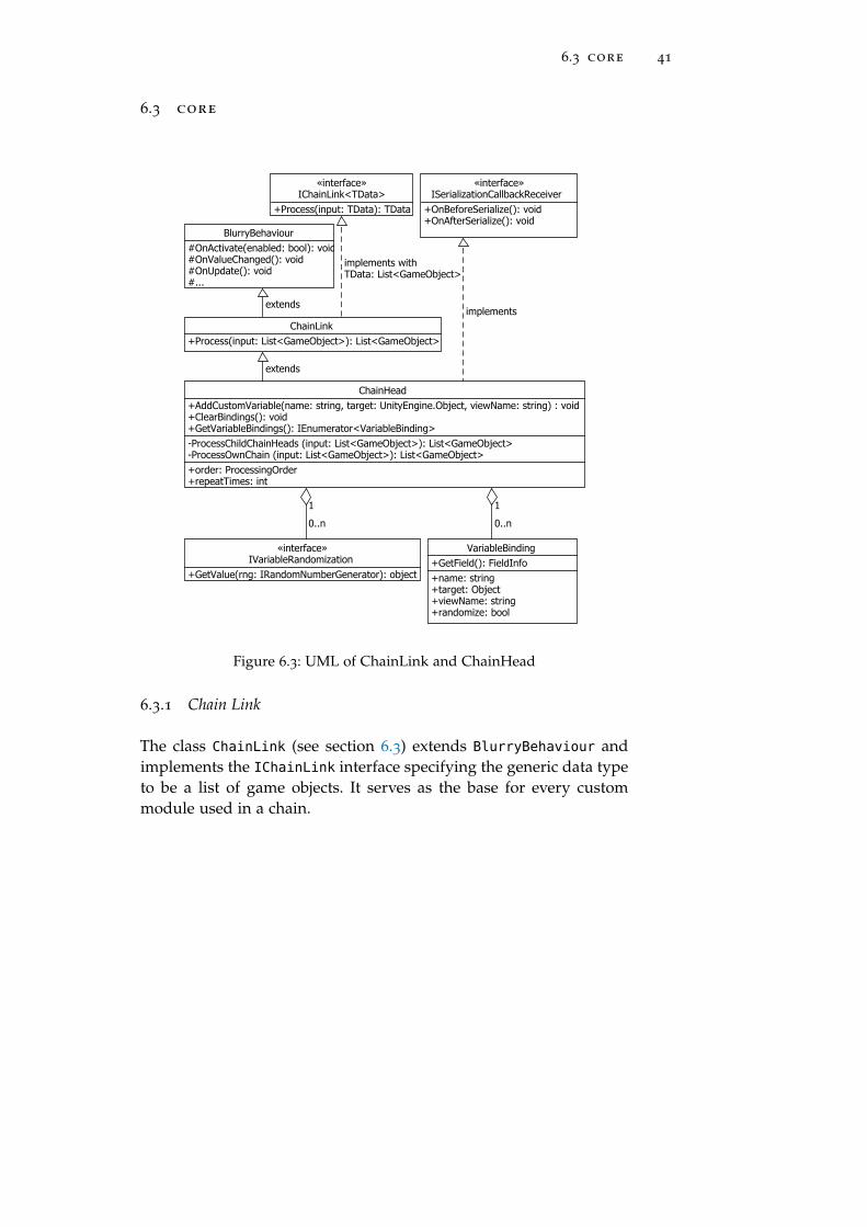
Figure 6.3: UML of ChainLink and ChainHead
6.3.1 Chain Link
The class ChainLink (see section 6.3) extends BlurryBehaviour andimplements the IChainLink interface specifying the generic data typeto be a list of game objects. It serves as the base for every custommodule used in a chain.

42 implementing the unity plugin velvet
6.3.2 Chain Head
The core module is called ChainHead (see figure 6.3). It in-herits from ChainLink, making it possible to have a chainhead part of a chain. Additionally ChainHead implements UnityISerializationCallbackReceiver interface for properly serializingall data. The head is responsible for managing all modules containedwithin its chain, as well as managing all custom variable bindings(see section 6.3.4).
Figure 6.4: Inspector view of a chain head
To create a chain, a game object must be created and associatedwith a chain head component. Every custom module component at-tached to this game object will then be taken into consideration, whenthe chain head is instructed to process its chain. This can either be theuser pressing the Process button or invoking the process function bycode. In the architecture overview, I mentioned the goal of not onlyhaving modules in a sequencial order, but also in a tree-like structure.To archive this, I made use of the already available scene graph struc-ture in Unity. A game object associated with a chain head can havechild game objects. These child objects can then in turn, have theirown chain head component as well as several custom modules.
When the user presses the Process button, the chain head will firstcheck in which order the child chain heads and the modules of itsown chain should be processed. This is done via a simple enumer-ation type called ProcessingOrder, presented to the user in a dropdown menu (see section 5.2.4). After this, the chain head initiatingthe process, queries its object hierarchy for all game objects whichare direct descendants and have a chain head component associatedwith them. The game objects will be kept in the same order as they ap-pear in the scene graph (see figure 6.5). These heads will then be told
Figure 6.5: Hirarchy overview of a chain generating trees
to process their chains one after another. If one of these chain headshappen to have child objects, these children would be processed ac-cording to the strategy configured in their ProcessingOrder.

6.3 core 43
With this approach, all chain head components get processed viaa depth-first strategy. Changing the position of a game object associ-ated with a chain head component within the hierarchy will therebychange the result.
6.3.3 Variable Bindings
To allow developers and designers to use the created chain as oneunit, it would be very handy to have all necessary variables in oneplace. This can be archived through binding variables. A binding iscreated via the chain head editor. When clicking the button Add newbinding, the developer is presented with an input mask (see section6.6). Here she can specify which game object should be selected. Oncea game object is selected, a list of attached modules will be shown. Af-ter selecting a module, the user will be able to select a public variableof the selected module to be bound. After typing in a descriptivename, the binding can be confirmed.
Figure 6.6: Window with mask to add new binding
From now on, every time the user views the inspector view forthis chain head component, it will display the created binding. Thetoggle button, deactivates or activates the randomization (see section6.3.4) of the bound variable. If a binding should not be necessary anymore, it is possible to delete it via the Clear button, or dispose of allbindings via the button Clear all bindings. To make binding variablespossible, I developed a set of editor extensions coupled with runtimetype reflection5. The first step is initiated by the user via the interfaceby dragging a game object associated with a chain head and modulesinto the game object field presented by the New binding window (seefigure 6.6).
When a game object is dropped into the according field, it is ex-amined to determine if it is actually associated with a chain headcomponent. If this is the case the algorithm then asks the chain headto retrieve all modules, associated with its game object. This list isthen rearranged to be visualized as drop down menu. After the userselects a module, it gets examined via reflection for any publicly avail-able field. All fields get collected into a list and presented to the userin yet another drop down menu.
5 Reflection is the ability of a program to inspect or manipulate its runtime metainformation, such as types.

44 implementing the unity plugin velvet
After having selected a field to be bound, the user is then asked tospecify a descriptive name to be displayed when the binding is com-pleted. You can now create the binding by clicking the Confirm button.When confirmed, the editor window then asks the chain head whichrequested the binding to be made to save a new VariableBinding.This value object contains all information necessary for the chain headto save, serialize and visualize the binding. Serialization turned outto be a bit cumbersome when working with a custom data structuredecoupled from Unitys object system. See section 6.3.5 for more infor-mation on serialization. Additionally after creating the binding, thesystem tries to determine how the bound variable might be random-ized.
6.3.4 Randomizations
By specifying a binding, a designer should basically be able to build acoherent structure, or blueprint for her creation. To have random vari-ations within this blueprint and therefor allowing for a diverse set ofresults, custom variable bindings can be initialized by custom valuerandomization. After a binding has been created, it can be random-ized, by clicking the button Randomize. When editing the randomiza-tion options a window is shown, presenting the options available tothe designer (see figure 6.7). The randomization system is based onspecific implementations for each data type, the developer wishes tobe randomized.
Figure 6.7: Randomization options for an integer value
As discussed previously all publicly available fields on a modulecan be bound. So if a developer writes a custom module using a datatype currently not supported, she has to also provide an implemen-tation of a interface IVariabelRandomization. This implementationwill then be used by the binding system to describe the process of ini-tializing a bound variable with random values. The type of variablewhich can be randomized with the implementation has to be specifiedvia a class level attribute called CustomRandomizer. Randomizationsget created when a new binding is set up. To instantiate a randomiza-tion depending on the type of variable ought to be bound, the factorymethod pattern is used (see figure 6.8).

6.3 core 45
«attribute»CustomRandomization+type: Type
ColorRandomization
FloatRandomization
IntegerRandomization
Vector3Randomization
caller
«interface»IVariableRandomization
+GetValue(rng: IRandomNumberGenerator): object
RandomizationFactory+CreateFromBinding (v: VariableBinding): IVariableRandomization
inspects type
produces
Figure 6.8: Factory pattern for creating randomizations
When asking the RandomizationFactory to create a randomization,it will use reflection to search the namespace Velvet.Randomizationsfor classes implementing the IVariabelRandomization and holdingattribute CustomRandomizer. It then examines the type of the boundvariable provided and looks for a randomization responsible for thistype. This allows custom randomizations to be written without theneed to manually extend the factory method.
6.3.5 Serialization
Serialization is the process of taking runtime data and convertingit to a different representation to be stored on hard-drive or trans-mitted over the network. To be able to save the chains including allrandomization options, it is necessary to do some manually serializa-tion. Normally Unity does a pretty good job of serializing all relevantdata from components, game objects, prefabs or assets you create orimport. There is however a problem when it comes to serializing Uni-tys standard types like a Vector3 or a Color. To serialize a class orstruct in a convenient way, it has to have a class level attribute calledSerializable, provided by the .NET framework. Unfortunatly mostof Unitys standard types do not contain this attribute. In order tocircumvent that problem, I created helper classes which have this at-tribute and mirror all public fields of its target class to serialize all nec-essary information. For example the Color value type has fields forred, green, blue and alpha. These fields are also provided by the classColorSerializable. When Unity is about to serialize its data all chainheads get notified via the implemented method OnBeforeSerialize()
provided by the ISerializationCallbackReceiver (see figure 6.3)interface. It then serializes each randomization into a binaryformat6, converting it to string and storing it into a list ofVariableRandomizationSerializable.
6 The binary format used here is base64.

46 implementing the unity plugin velvet
This list is a private field and marked with an attribute providedby Unity called SerializeField. Normally only public fields get se-rialized by Unitys built-in serializer. If a less visible field is markedwith the SerializeField the built-in serializer will include this fieldin the serialization and deserialization process. When Unity is aboutto deserialize its data, the chain heads will also get notified via asecond method called OnAfterDeserialize(), also provided by theserialization callback interface. In this method each element in thelist of VariableRandomizationSerializable will be deserialized andstored in its runtime representation.
6.4 editor extension
The second part is the extension of Unitys visual editor, enablingthe user to add, remove and control modules within a chain andcreate bindings to variables from modules within a chain. All codeextending Unitys editor has to be contained in a directory namedEditor. When scanning the project directories Unity will then collectthese scripts and create a separate project from the normal sourcecode. Unity allows developers to redefine to some extend how dataassociated with your application is present, created or manipulated.The basic structure of Unitys interface are windows (see figure 6.9).
Figure 6.9: Numbered Window overview of Unitys standard interface
A window is a resizable canvas which can be placed freely withinthe main application window of Unity. It can be tapped, horizontallystacked or vertically aligned.

6.4 editor extension 47
windows shown in figure 6 .9 :
inspector (1) The Inspector Window displays the currently se-lected game object and its associated components.
scene (2) In the Scene Window the user can move through thecurrently loaded scene, create, select and manipulate game objectsthem.
game (3) The Game Window shows the game from the perspec-tive of the currently active camera of the scene.
console (4) The Console Window shows errors, warnings andlog outputs to help debug your game.
hierarchy (5) Displays all objects contained in the current scene,the Hierarchy Window allows the developer to create, select and ma-nipulate game objects directly though a textual representation of thescene view.
project (6) In the Project Window, all directories and game assetsare displayed, can be created, renamed, moved or deleted.
6.4.1 Custom Property Drawer
When creating a custom component, a developer is able to tell Unityhow this component should look in the inspector view. The simplestway would be to create a custom property drawer. As far as Unityis concerned, a property is any public field on a component (not tobe confused with C# properties!). When loading a component Unitylooks for publicly available field and tries to draw a representationfor it. Every built-in simple type 7 provided by the basic .NET frame-work and most of Unitys core library types can be drawn by thedefault PropertyDrawer. If you need more than customized ways ofdisplaying public fields you would have to implement a custom edi-tor.
7 See http://web.archive.org/web/20160219110405/https://msdn.microsoft.com/
en-us/library/s1ax56ch.aspx for more on simple types.

48 implementing the unity plugin velvet
6.4.2 Custom Editor
When creating a complex component, which should be presented ina special way, developers can create a custom inspector editor. Thiseditor is responsible for rendering a component when viewed thoughthe inspector window (see section 6.9). To create such an editor, de-velopers can extend a base class called Editor. To tell Unity how thiseditor should be used, the class level attribute CustomEditor has tobe applied, which expects the class type of a component for whichthe custom editor is responsible for. You can now override a functioncalled OnInspectorGUI, which gets called whenever Unity wants to re-draw parts of its interface. For interface elements like labels, buttons,dropdown menus or checkboxes Unity provides a couple of staticclasses exposing functions to draw a certain element. If a developerwants to present text box with an editable floating point number, shecould used the following function:
value = EditorGUILayout.IntField ("value", value); �The functions provided by EditoGUILayout will be positioned by
Unity dynamically when drawing the interface in contrast to justEditoGUI. This is very handy if you have interface elements whichmight change their dimensions depending on the value they currentlyhave.
6.4.3 Custom Window
Being the corner stone of Unitys visual editor, developers can alsocreate their own custom editor windows. This is used in Velvet forthe window to add new bindings, as well as the window to edit avariable randomization. To create a custom window, a class has toinherit from EditorWindow. It then can override a method called OnGUI
which will be called when Unity is about to redraw its interface. Toopen a window, a generic factory method provided by Unity calledGetWindow has to be called.

6.4 editor extension 49
6.4.4 UI Architecture
The design for the user interface extension part of the plugin is basedon the idea of separating presentation and logic. One architecturalpattern often used in such a case is the MVC pattern, on which Iloosely based this architecture (see figure 6.10).
«interface»IEnumerable<TData>
+GetEnumerator(): IEnumerator<TData>
ChainHeadModel-bindings: IEnumerator<VariableBinding>
BindingListModel+HasEnumerator(): bool-bindings: IEnumerator<VariableBinding>
VariableBindingView#UpdateAndDrawValue(value: object): object
BindingListView+OnAddBinding: event+OnClearAllBindings: event+OnEditBinding: event+OnRemoveBinding: event
«interface»IView
+Draw(): void
ChainHeadView+OnProcess: event+OnAddBinding: event+OnClearAllBindings: event+OnEditBinding: event+OnRemoveBinding: event
Editor+OnInspectorGUI(): void+...
ChainHeadEditor-OnProcess(): void-OnAddBinding(): void-OnEditBinding(v: VariableBinding): void-OnRemoveBinding(v: VariableBinding): void-OnClearAllBindings(): void-OnAddCustomVariable(module: Object, name: string, target: Object, alias: string): void
implements withTData: VariableBinding
implements
0..n
implementsimplements
extends
Figure 6.10: Architecture overview
A model is responsible for storing data, while the view is con-cerned with how the data should be presented to the user. The con-troller is where the interaction logic is implemented. Instead of hav-ing a dedicated controller, the basis for managing views and modelswill be the classes inheriting from Editor or EdiorWindow.
chain head editor The ChainHeadEditor is the central part forinteracting with a chain head component through the inspector win-dow of the unity interface. It inherits from Unitys Editor base classand overrides OnInspectorGUI().

50 implementing the unity plugin velvet
Specifying the class level attribute CustomEditor with the type ofChainHead, it instructs Unity to use ChainHeadEditor when renderinga chain head component instead of the standard view.
chain head view When the chain head editor is asked to draw,it uses a view called ChainHeadView. This class knows how to dis-play a ChainHead and has several events to which ChainHeadEditor
can subscribe. This would be for example when the Process buttonis pressed. The chain head view in turn splits the rendering of itsdifferent areas into multiple sub-views.
binding list view After showing the variables for processingorder and repeat times as well as rendering the Process button, thechain head view instructs BindingListView to show the list of cur-rently bound variables. The binding list view first shows the buttonto add a new binding as well as a button to clear all bindings. Ifthere is at least one binding, the binding list creates a view for thevariable and repeats until all variables have been drawn. This is donevia the help of the iterator pattern. C# has a build in interface calledIEnumerator which is used by the foreach loop. Such an enumeratoror iterator can be obtained via the method GetEnumerator which ispart of the IEnumerable interface.
variable binding view Each binding gets drawn by a view ex-tending VariableBindingView (see figure 6.11).
...UpdateAndDrawValue(value)...
caller
«interface»IView
+Draw(): void
VariableBindingView
#UpdateAndDrawValue(value: object): object
Vector3BindingView
IntegerBindingView
GameObjectBindingView
FloatBindingView
ColorBindingView
VariableBindingViewFactory+CreateFromVariable(v: VariableBinding): VariableBindingView
implements
produces
Figure 6.11: Specializations to draw different types of variables
This is because in order to draw a floating point number youhave to use different parts of Unitys editor api than for example fordrawing a color value or a string. By implementing the protected ab-stract method UpdateAndDrawValue each specialization can make useof whatever api is needed to get the value displayed and retrieve anew value in case it has been changed via the user interface.

6.4 editor extension 51
The method then gets internally called when the public drawmethod is invoked. This design is based on the template method pat-tern.
ChainHeadEditor-OnAddBinding(): void-OnAddCustomVariable(module: Object, name: string, target: Object, alias: string): void-...
«interface»IView
+Draw(): void
AddVariableBindingView+OnAddCustomVariable: event
EditorWindow+OnGUI(): void+...
AddVariableBindingEditor+OnAddCustomVariable: event
notifiesasks to show
notifies
calls
implements
extends
Figure 6.12: UML for adding a new binding
adding a binding Variable bindings are created through a cus-tom editor window (see figure 6.12). This window is created by thechain head editor when the user presses the Add new binding button.This click invokes the event handler method OnAddBinding which in-structs the AddViariableBindingEditor to show its view (see figure6.6). When all options are specified and the user presses the Confirmbutton, the chain head editor is notified. It in turn will then instructthe chain head to save a new binding.
EditVariableBindingView+OnToggleRandomization: event
«interface»IView
+Draw(): void
EditorWindow+OnGUI(): void+...
EditVariableBindingEditor+OnToggleRandomizeVariable: event
ChainHeadEditor-OnEditBinding(v: VariableBinding): void-OnToggleRandomizeVariable (v: VariableBinding, state: bool): void-...
implements
calls
notifies
extends
notifiesasks to show
Figure 6.13: UML for editing a binding
editing a binding After a binding has been created, it is possi-ble to configure its randomization options (see figure 6.7) by pressingthe Randomize button. The structure and flow is modeled after thesame concept applied to add a new binding. The chain head editortells the EditVariableBindingEditor to show its window.

52 implementing the unity plugin velvet
The edit variable binding editor, will then use its view to displaythe randomization and notifies the chain head editor in case a valuehas been changed. To visualize the custom randomization used for aspecific data type, I created a extendable system; again based on thefactory method pattern.
VariableBinding+name: string+target: Object+viewName: string+randomize: bool
«attribute»CustomRandomizationView+type: Type
ColorRandomizationView
FloatRandomizationView
IntegerRandomizationView
Vector3RandomizationView
«interface»IVariableRandomization
+GetValue(rng: IRandomNumberGenerator): object
caller
«interface»IView
+Draw(): void
VariableRandomizationViewFactory+Create (IVariableRandomization variable): IView
inspects type
produces
Figure 6.14: Factory of randomization views
randomization view To display a custom randomization inthe randomization option window (see figure 6.7), a similar sys-tem to the binding factory and binding view factory is appliedhere too. When a randomization is about to be displayed it exam-ines the type of randomization and searches for a class holding aCustomRandomizationView attribute specifying that type of random-ization.

7E X A M P L E S
7.1 prologue
To test drive the plugin, I created two examples using Velvet. Thefirst one uses Bézier Curves and the Superformula to create organiclooking cylindrical shapes. The following example creates a blockworld based on Perlin noise. And the third shows the re-use of somecomponents of the two examples before to create curved and twistedtunnels.
7.2 supercylinders
In this examples I made use of the Superformula to create polygonsand a Bézier spline to describe a curve on which I want to positionsaid polygons. After placing the polygons I went through all verticesand build a mesh based on a cylinder; hence the name Supercylinders.I split the responsibility into three modules.
7.2.1 Modules
polygon generator Generating a flat polygon on the basis ofthe Superformula is done via the SupershapePolygonGenerator. Itcan be parameterized with the radius in Unity units, the amount ofvertices used to describe the polygon and the five parameters used bythe Superformula (see figure 3.4). It produces a set of game objectsholding a mesh with vertices representing a Supershape polygon.
position along bézier path mutator This module takes aset of game objects and positions them along a Bézier curve. Aftersetting the positions the game objects get also rotates them so theirforward vector faces the tangent of the curve point. It can be param-eterized by setting the positions of P0 and point P1 as well as thecontrol points of the Bézier Curve. Additionally I added an editorextension for this module to show custom gizmos 1 in the scene view.
1 A gizmo is an visual aid like the position handle to help manipulate objects in thescene view.
53

54 examples
With this gizmos it is possible to control the two points and theirrespective control points of the curve. You can also preview how thepoints along the curve will be position via gizmos showing the nor-mal in red and tangent in yellow (see figure 7.1).
Figure 7.1: Bézier curve gizmos
mesh generation Generating the complete model from poly-gons is the responsibility of this module (see figure 7.2). It fetchesthe vertices of the mesh associated with a game object and createstriangles on the assumption that the resulting shape is cylindrical innature. This is done by first creating quads2 between every set of twoadjacent vertices of polygon Pi and Pi+1.
Figure 7.2: Shaded wireframe view of cylindric mesh
The quad can then be split into two triangles respectively. Aftertriangulating the walls of the cylinder the generator also triangulatesthe front polygon P0 and back polygon Pi+n−1 so the cylinder is closedoff. The algorithm used here just takes the first vertex V0 of the poly-gon P and triangulates with two vertices Vk and Vk+1 where k ≥ 1and is incremented by 2 while k ≤ (|V| − 1). I used this approach,due to its simple implementation, but it will unfortunately lead tostrange results when having concave or star-shaped polygons.
2 A quad is a polygon with four vertices. It is sometimes used as the base element ofsurfaces of complex polygons instead of triangles.

7.2 supercylinders 55
7.2.2 Generation process
Figure 7.3: Supercylinder gener-ation tree
To control the generation processI created a nested structure. Thepolygon_generator object contains achain head an the polygon generatormodule. I separated this module in itsown chain so I can repeatedly gener-
ate polygons to control the amount of resolution I get in the cylinder.Containing the polygon_generator object supercylinder_generatorholds a chain head the Bézier curve module and the mesh generatormodule. By setting the process order to post, I make sure the childobject is processed first. In this case this will first produce the desiredamount of polygons, which will then be passed to the Bézier moduleand finally to the mesh generator module. The figure 7.4 shows fourexamples of Supercylinders I created using this chain.
7.2.3 Results
(a) 2; 1; 4; 8; (b) 4; 2; 9; 6;
(c) 3; 3; 14; 2; (d) 9; 9; 8; 9;
Figure 7.4: Supercylinders based on Supershapes (m; n1; n2; n3; a = b = 1)

56 examples
7.3 block world terrain
In this example, voxels in the shape of cubes get placed on the basisof an height map. This height map is produced by sampling a Perlinnoise function multiple times as described in section 3.2.
7.3.1 Modules
prefab instance generator This generator module is respon-sible for instantiating game objects on the basis of a prefab. A prefabis like a recipes, used by Unity to remember how a game object witha specific set of components should be created. In this case it wouldbe the voxel. A voxel is just a game object containing a cube meshcomponent and a mesh renderer component.
terrain generator The terrain generator takes a set of gameobjects and arranges them on the basis of a height map. It will alsocolor each game object on the basis of its height on the height map.This is done through the use of a noise texture generated by a Perlinnoise function provided by Unity. When the texture is generated, itthen will be traversed and its values, which range from 0 to 1 getinterpreted as heights. Each height range gets assigned a color cor-responding to water (blue), flat land (yellow and green), mountains(gray) and mountain tops (white).
reparent collector This module takes a set of game objectsand attaches them to a newly created parent game object. This al-lows for a easier handling of composite structures so the scene graphdoesn’t get cluttered.

7.3 block world terrain 57
7.3.2 Generation Process
All modules are contained within on chain. The first module gener-ates all voxel needed to form the terrain. These generated voxels willthen be modified by the second module which applies a height off-set and color depending on the generated height map. The reparentmodule will then take the modified voxels and attaches them to acommon parent, so the map can be handles as one object.
7.3.3 Results
(a) (b)
(c) (d)
Figure 7.5: Generated voxel landscapes

58 examples
7.4 vortex tunnels
To examine the reusability of modules, this examples also makes useof the Prefab Module, Bézier Path Module and Reparent Module togenerate curved and twisted vortex-like tunnel structures.
7.4.1 Modules
prefab instance generator See Block World example (sec-tion 7.3.1).
scale mutator Changes the scale factor of a game object to thescale defined in the parameters of this module.
color mutator Changes the color of a game object to the colorspecified in this modules parameters.
circular placement mutator This module takes its inputgame objects and arranges them on a circular path. It is possible tospecify the radius of the circle used to create the path.
reparent collector See Block World example (section 7.3.1).
position along bézier path mutator See Supercylinder ex-ample (section 7.2.1).
partial rotation mutator With this module, all input gameobjects get rotate a certain angle. This angle depends on the param-eters Start Angle and End Angle, as well as the game objects positionin the input list. So if the start is at 0◦ and the end at 360◦ a gameobject in at index 1 in a list of 3 objects would have the rotation 180◦.It is also possible to specify if the rotation should happen in the gameobjects local space or in global space and which angle should be usedto rotate around.
Figure 7.6: Vortex generator bindings

7.4 vortex tunnels 59
7.4.2 Generation Process
Figure 7.7: Vortex generation tree
The generation of this shapeis managed by several nestedchains. First a set of objectsdefined by a prefab are gen-erated by generate_and_place.They then get handed down toscaler to changed the scale fac-tor and color_rows to re-colorthe objects. The instances then get handed up to collect, placedon a circular path and re-parented to form a group. The objectcircular_object_generator acts as a separator to allow the gener-ation of as many circularly placed object groups as needed. After thisstacker has modules to place the groups along a Bézier curve and ro-tated them described in section 7.4.1, as well as yet again re-parentedto form a single object. Finally vortex_generate acts as a hub objectand holds all bindings to the important parameters of the moduleswithin the tree (see figure 7.6).
7.4.3 Results
(a) Tunnel of Cubes (b) Tunnel of Spheres
(c) Tunnel of Cubes (d) Tunnel of Suzannes
Figure 7.8: Vortex Tunnels along a Bézier Curve


Part III
C L O S I N G W O R D S
Following the concept and its prototypical implementa-tion, this chapter will be about taking a look on how wellthe goals set in the introduction of this thesis have beenmet. I will then give a short summary of what has beendiscussed in this thesis and what further work could bedone on the basis of this work.


8E VA L U AT I O N
8.1 prologue
In this chapter I will take a look at how well I met my goals set outin the introduction of this thesis. I will also try to give an impressionon what advantages and disadvantages the proposed concept and inturn the prototypical implementation has.
8.2 developing modules
The goals described in section 1.4.1 state the importance of not havinginter-dependencies and information sharing between modules. Afterimplementing the prototype and developing a set of modules to pro-duce the examples presented in section 7, it turned out to be veryhard to really have no assumptions or knowledge about the informa-tion in the input certain modules will receive. In the Supercylinder(see 7.2) example, I developed a module concerned with constructiona mesh from a set of vertices representing flat Supershape planes. Init I had to assume the shapes come in a circular polygon withoutholes. I guess it is necessary to have certain requirements on the in-formation fed to a module for it to really be able to solve a specificproblem. Chainability, as stated in the goals section (see 1.4.2) as wellas nestability (see 1.4.3) have been archived through the design of theplugin based on the composite pattern in combination with Unitysscene graph.
8.3 development of velvet
Another goal set out in the beginning of this thesis, was the integra-tion of the module workflow into the Unity eco-system. This has beenrealized by developing the plugin Velvet which adapts the library toUnitys ECS and makes use of the scene graph already available inUnity. To allow for a more convenient use of the generation system, Ialso created a set of editor extension within Velvet allowing design-ers to bind variables of modules, allowing for the parametrization(see 1.4.6) of a chain.
63

64 evaluation
8.4 controlling the generation process
Structuring the generation process through the use of Unitys scenegraph proves to be valuable when creating a hierarchy of responsi-bilities. This approach also allows for an easy way of saving chainsthrough the use of prefabs. Because all modules are components at-tached to a game object, this game object can just be linked as a pre-fab, enabling the user to use it as a predefined chain in more thanone place. Changes made in the prefab object will then be appliedto all instances. Being able to tell a chain head how many times itshould be processed, as well as defining the order of execution ofits own chain and child modules helped building a flexible system.Initializing bound variables with random values through the use ofcustom variable randomizations has also proven very valuable to getvariety on the content created through the use of a chain. There arehowever certain limitations on controlling the flow of the generation.It is for example not possible to hold state. If a chain head is invokedmultiple times, it has no knowledge how many times it has beenprocess before. This might be conquered by implementing a customset of selector modules. Although practical and functional, the use ofgame objects and components to represent the generation tree feels abit cumbersome. I think the use of a node based editor would havegreatly benefited the user experience.
8.5 user interface
Initially I though of a node editor as the basis for handling the cre-ation of chains. Comparable to Blenders 1 node editor (see figure8.1) the user would have connect modules and build up a generationgraph that way.
Figure 8.1: Blender 2.67 Node Editor
1 Blender is an free and open source 3D modeling, rendering and animation tool.http://web.archive.org/web/20160222121343/https://www.blender.org/

8.6 performance 65
Due to a multitude of challenges, like the integration of node visu-alizations into the Unity editor or the concept of having input frommore than on module being fed into another module led me to aban-don this approach. There are however interesting commercial Plug-ins in Unitys asset store, featuring node based editing 2, which couldcome in handy for future work. However in place of the node editor,I created a UI system which made use of the basic editor elements al-ready in place: the inspector view and custom editor windows. Com-bined with the scene graph, this approach turned out to work verywell. With a reasonable amount of work, basically any type of moduleof any type of data can be displayed in the inspector view by writingcustom editor scripts for the modules and extending the view systemof Velvet for the visualization of bindings and randomizations. Al-though I think the system to create bindings is functional, the factthat a user has to drag and drop the game object into the new bind-ing window feels a bit cumbersome. It also bears the risk of havinga binding to a module which is not necessary in the same processtree as the head to which it should be bound. I think this might havebeen better implemented as a tree view offering the user a selectionof modules which are actually contained within the object tree.
8.6 performance
Due to the fact, that the primary data type used in the prototype is alist of game objects, the base unit of information used by chains hasto be contained within a game object. This might lead to an substan-tial amount of game objects being instantiated, which could impactmemory and computational resources. It might be interesting to usea more varied set of types to use in the generic chain link system tosee if there are advantages to CPU processing time or memory con-sumption.
2 https://www.assetstore.unity3d.com/en/#!/content/29435 (visited 28.02.2016)


9C O N C L U S I O N
9.1 prologue
Summarizing what has been discussed in this thesis as well as givingan outlook of what future work might be done with Velvet will bethe topic of this chapter.
9.2 summary
In this thesis I looked at some examples of how Procedrual ContentGeneration (PCG) has been used in video games and also what re-cent research has found in some specific areas of PCG. I also exam-ined a set of techniques and examples of areas of application. Thisis followed by the presentation of a modular workflow concept forprocedurally generating content and the description of Velvet, a pro-totypical plugin implementation for Unity. To show the how to workwith Velvet a set of examples have been discussed.
9.3 further work
9.3.1 Different chain implementations
Currently chains can only process their modules in one go. Whentrying out different combinations of modules, it would have been in-teresting for a chain to process its modules over time. This wouldhave allowed for deferred generation, or possibly even procedural an-imation. In generation trees where nested chains could work concur-rently, a chain type featuring asynchronous processing might increaseperformance.
67

68 conclusion
9.3.2 Modularization
I think it might be interesting to investigate further into the topic ofmodularization in the context of procedural generation. Evaluatinghow beneficial the splitting of work in a complex generation systemis and what value it might bring to the developer or designer. Maybethere are specific scenarios where modularization is very fitting, likefor example the generation of worlds or levels described in the sec-tion about Dwarf Fortress (see section 2.2.5). There might howeverbe tasks which do not lend themselves very well to separation. Nev-ertheless, in my opinion, separating parts of a system into smallermodules could benefit the way one approaches procedural genera-tion, by not thinking of a system as one unchangeable recipe, but asa set of responsibilities; potentially exchangeable without loosing theoverall concept.

Part IV
A P P E N D I X


AA P P E N D I X
a.1 life
The rules for Life, though up by mathematician John Horton Conway,are based on a celluar automaton. A concept developed by John vonNeuman and published in 1966 [34]. Figure A.1 shows four snapshotsover 2644 generations of Life
1.
(a) Generation 0 (b) Generation 6
(c) Generation 42 (d) Generatio 2644
Figure A.1: Snapshots over 2644 generations of “life”
The board is made up of cells, which in turn can have 3 differentstates making up a generation (see table A.1).
1 Screenshots from a javascript implementation [56] by Pedro Verruma http://web.
archive.org/web/20160109155314/http://pmav.eu/
71

72 appendix
The game is played according to three simple rules[17]:
state colour meaning
Untouched Grey Has never been alive in any genration before.
Alive Blue Is alive in the current generation.
Dead Green Has been alive in a generation before the current one.
Table A.1: States of a generation in Life
survivals Every counter with two or three neighboring counterssurvives for the next generation.
deaths Each counter with four or more neighbors dies (is removed)from overpopulation. Every counter with one neighbor or nonedies from isolation.
births Each empty cell adjacent to exactly three neighbors–no more,no fewer–is a birth cell. A counter is placed on it at the nextmove.
Although simple, Conway later (originally in 1982) published [1]proof for the existence of a universal constructor 2. Later research [45]on Life lead to the conclusion of computational universality equal toa Turing Machine. In his publication On computable numbers, with anapplication to the Entscheidungsproblem Turing states:
“It is possible to invent a single machine which can beused to compute any computable sequence. “ [54]
The Turing machine a mathematical concept named after its inventorAlan Turing, showing the fundamental capabilities and limitations ofa computation device.
2 A non-trivial self-reproducing machine [30].

A.2 fibonacci like series 73
a.2 fibonacci like series
Below are the listings used to generate the statistics mentioned insection 2.2.2.1.
a.2.1 Basic Algorithm
# splits off the last digit of any given number n
def get_last_digit (n):_k, r = divmod (n, 10)
return r
# generates a list of numbers in a fibonacci fashioned series
# in the form [a, b, (a, b), (b + (a + b)), ...], except each
# entry correspons only to the last digit of its original number
def generate_elite_fibo_list (a, b, length):
x = get_last_digit (a)
y = get_last_digit (b)
z = 0
r = [x, y]
for i in range (0, length):
z = get_last_digit (x + y)
r.append (z)
x = y
y = z
return r
Listing A.1: Fibonacci like series used in Elite

74 appendix
a.2.2 Generating the data
import elite_fibonacci as efib
# generates a list of fibo lists
def generate_samples (al, bl):
n = 10
samples = []
for a in range (0, al):
for b in range (0, bl):
l = efib.generate_elite_fibo_list (a, b, n)
samples.append (l)
return samples
def get_stats ():
samples = generate_samples (10, 10)
occurences = dict ()
for i in range (0, 10):
occurences[i] = 0
for sample in samples:
for number in sample:
occurences[number] = occurences[number] + 1
total = float (sum (occurences.values ()))
percentages = dict ()
for number in occurences:
percentages[number] = float (occurences[number]) / total
return occurences, percentages
Listing A.2: Statistic utilty for elite fibonacci

BR E F E R E N C E S
Here you’ll find references to the figures, tables, listings andacronyms used throughout the thesis.
L I S T O F F I G U R E S
Figure 2.1 Creative artistic rendering of how Roguelooked on an IBM PC (by Michael Toy, KennethC.R.C. Arnold, Jo licensed under CC BY-SA 3.0) 12
Figure 2.2 Distrubtion of each number from 0 - 9 . . . . . 14
Figure 3.1 Noise Textures . . . . . . . . . . . . . . . . . . . 19
Figure 3.2 Superposition of Noise . . . . . . . . . . . . . . 20
Figure 3.3 Supershapes generated with the Superformula 22
Figure 3.4 Superformula in polar coordinates . . . . . . . 22
Figure 3.5 Concpet of a Cubic Bézier curve (Based onpublic domain work of Marian Sigler) . . . . . 23
Figure 3.6 Cubic Bézier Curve . . . . . . . . . . . . . . . . 23
Figure 5.1 Composite design pattern . . . . . . . . . . . . 32
Figure 5.2 UML IChainLink . . . . . . . . . . . . . . . . . 33
Figure 5.3 UML Chain . . . . . . . . . . . . . . . . . . . . . 33
Figure 6.1 Unity game object . . . . . . . . . . . . . . . . . 37
Figure 6.2 Velvet structure . . . . . . . . . . . . . . . . . . 40
Figure 6.3 UML of ChainLink and ChainHead . . . . . . 41
Figure 6.4 Inspector view of a chain head . . . . . . . . . 42
Figure 6.5 Tree strucutre . . . . . . . . . . . . . . . . . . . 42
Figure 6.6 Add binding view . . . . . . . . . . . . . . . . . 43
Figure 6.7 Randomization options . . . . . . . . . . . . . . 44
Figure 6.8 Randomization factory . . . . . . . . . . . . . . 45
Figure 6.9 Unity interface . . . . . . . . . . . . . . . . . . . 46
Figure 6.10 Architecture overview . . . . . . . . . . . . . . 49
Figure 6.11 Variable binding view . . . . . . . . . . . . . . 50
Figure 6.12 UML for adding a new binding . . . . . . . . . 51
Figure 6.13 UML for editing a binding . . . . . . . . . . . . 51
Figure 6.14 Randomization views . . . . . . . . . . . . . . . 52
Figure 7.1 Bézier curve gizmos . . . . . . . . . . . . . . . . 54
Figure 7.2 Shaded wireframe . . . . . . . . . . . . . . . . . 54
Figure 7.3 Supercylinder generation tree . . . . . . . . . . 55
Figure 7.4 Supercylinders . . . . . . . . . . . . . . . . . . . 55
75

Figure 7.5 Generated voxel landscapes . . . . . . . . . . . 57
Figure 7.6 Vortex generator bindings . . . . . . . . . . . . 58
Figure 7.7 Vortex generation tree . . . . . . . . . . . . . . 59
Figure 7.8 Vortex Tunnels . . . . . . . . . . . . . . . . . . . 59
Figure 8.1 Blender 2.67 Node Editor . . . . . . . . . . . . 64
Figure A.1 Life . . . . . . . . . . . . . . . . . . . . . . . . . 71
L I S T O F TA B L E S
Table 3.1 Simple L-System rule set . . . . . . . . . . . . . 21
Table 3.2 Five L-System generations . . . . . . . . . . . . 21
Table 5.1 Processing order . . . . . . . . . . . . . . . . . . 34
Table A.1 Life states . . . . . . . . . . . . . . . . . . . . . . 72
L I S T I N G S
Listing A.1 Fibonacci like series used in Elite . . . . . . . . 73
Listing A.2 Statistic utilty for elite fibonacci . . . . . . . . . 74
A C R O N Y M S
PCG Procedrual Content Generation
MASSIVE Multiple Agent Simulation System in Virtual Environment
PRNG Pseudo-Random Number Generator
BAM Beneath Apple Manor
ECS Entity-Component System
L-System Lindenmayer-System
MVC Model-View-Controller
MMO Massive Online Multiplayer
MMVE Massively Multi-user Virtual Environments
76

B I B L I O G R A P H Y
[1] Elwyn R Berlekamp, John H Conway, and Richard K Guy. Win-ning ways for your mathematical plays, volume 4. AMC, 10:12,2003. (Cited on page 72.)
[2] Axel Berndt, Raimund Dachselt, and Rainer Groh. A surveyof variation techniques for repetitive games music. In Proceed-ings of the 7th Audio Mostly Conference: A Conference on Interac-tion with Sound, AM ’12, pages 61–67, New York, NY, USA, 2012.ACM. ISBN 978-1-4503-1569-2. doi: 10.1145/2371456.2371466.URL http://doi.acm.org/10.1145/2371456.2371466. (Cited onpage 27.)
[3] Emma Boyes. Q & a: David braben - from eliteto today, 2006. URL http://web.archive.org/web/
20140322152829/http://www.gamespot.com/articles/
qanda-david-braben-from-elite-to-today/1100-6162140/.(Cited on page 13.)
[4] Dong Joo Byun, Henrik Falt, Ben Frost, Mir Ali, Eric Daniels, Pe-ter De Mund, and Michael Kaschalk. Procedural animation tech-nology behind microbots in big hero 6. In ACM SIGGRAPH 2015Talks, SIGGRAPH ’15, pages 40:1–40:1, New York, NY, USA, 2015.ACM. ISBN 978-1-4503-3636-9. doi: 10.1145/2775280.2792533.URL http://doi.acm.org/10.1145/2775280.2792533. (Cited onpage 26.)
[5] Alessandro Canossa. Give me a reason to dig: Qualitative associ-ations between player behavior in minecraft and life motives. InProceedings of the International Conference on the Foundations of Dig-ital Games, FDG ’12, pages 282–283, New York, NY, USA, 2012.ACM. ISBN 978-1-4503-1333-9. doi: 10.1145/2282338.2282400.URL http://doi.acm.org/10.1145/2282338.2282400. (Cited onpage 18.)
[6] B. Carter. The Game Asset Pipeline. Charles River Me-dia Game Development. Charles River Media, 2004. ISBN9781584503422. URL https://books.google.de/books?id=
Sr2HKC46ImcC. (Cited on page 7.)
[7] Sherol Chen, Adam M. Smith, Arnav Jhala, Noah Wardrip-Fruin,and Michael Mateas. Rolemodel: Towards a formal model ofdramatic roles for story generation. In Proceedings of the Intel-ligent Narrative Technologies III Workshop, INT3 ’10, pages 17:1–17:8, New York, NY, USA, 2010. ACM. ISBN 978-1-4503-0022-
77

78 bibliography
3. doi: 10.1145/1822309.1822326. URL http://doi.acm.org/10.
1145/1822309.1822326. (Cited on page 26.)
[8] Arthur Charles Clarke. The exploration of space. Harper, 1959.(Cited on page v.)
[9] Kate Compton, James Grieve, Ed Goldman, Ocean Quigley,Christian Stratton, Eric Todd, and Andrew Willmott. Creatingspherical worlds. In ACM SIGGRAPH 2007 Sketches, SIGGRAPH’07, New York, NY, USA, 2007. ACM. doi: 10.1145/1278780.1278879. URL http://doi.acm.org/10.1145/1278780.1278879.(Cited on page 17.)
[10] Leonardo G. de Freitas, Luiggi Monteiro Reffatti, Igor Rafaelde Sousa, Anderson C. Cardoso, Carla Denise Castanho, RodrigoBonifácio, and Guilherme N. Ramos. Gear2d: An extensiblecomponent-based game engine. In Proceedings of the InternationalConference on the Foundations of Digital Games, FDG ’12, pages81–88, New York, NY, USA, 2012. ACM. ISBN 978-1-4503-1333-9. doi: 10.1145/2282338.2282357. URL http://doi.acm.org/10.
1145/2282338.2282357. (Cited on page 36.)
[11] David (grue) DeBry, Henry Goffin, Chris Hecker, Ocean Quigley,Shalin Shodhan, and Andrew Willmott. Player-driven procedu-ral texturing. In ACM SIGGRAPH 2007 Sketches, SIGGRAPH ’07,New York, NY, USA, 2007. ACM. doi: 10.1145/1278780.1278878.URL http://doi.acm.org/10.1145/1278780.1278878. (Cited onpage 17.)
[12] Herman Arnold Engelbrecht and Gregor Schiele. Koekepan:Minecraft as a research platform. In Proceedings of Annual Work-shop on Network and Systems Support for Games, NetGames ’13,pages 16:1–16:3, Piscataway, NJ, USA, 2013. IEEE Press. ISBN978-1-4799-2961-0. URL http://dl.acm.org/citation.cfm?id=
2664633.2664652. (Cited on page 18.)
[13] Clara Fernández-Vara and Alec Thomson. Procedural genera-tion of narrative puzzles in adventure games: The puzzle-dicesystem. In Proceedings of the The Third Workshop on Procedural Con-tent Generation in Games, PCG’12, pages 12:1–12:6, New York, NY,USA, 2012. ACM. ISBN 978-1-4503-1447-3. doi: 10.1145/2538528.2538538. URL http://doi.acm.org/10.1145/2538528.2538538.(Cited on page 26.)
[14] Dejobaan Games. Procedural content generation: Thinkingwith modules, 2012. URL http://web.archive.org/web/
20150820154248/http://www.gamasutra.com/view/feature/
174311/procedural_content_generation_.php. (Cited onpage 31.)

bibliography 79
[15] GameSpot. How does no man’s sky actually work? - re-ality check, 2014. URL https://www.youtube.com/watch?v=
ZVl1Hmth3HE. (Cited on pages 4 and 5.)
[16] Erich Gamma, Richard Helm, Ralph Johnson, and John M.Vlissides. Design Patterns: Elements of Reusable Object-Oriented Software. Addison-Wesley Professional, 1 edition,1994. ISBN 0201633612. URL http://www.amazon.com/
Design-Patterns-Elements-Reusable-Object-Oriented/dp/
0201633612/ref=ntt_at_ep_dpi_1. (Cited on page 8.)
[17] Martin Gardner. Mathematical games the fantastic com-binations of john conway’s new solitaire game "life", 2009.URL http://web.archive.org/web/20090603015231/http:
//ddi.cs.uni-potsdam.de/HyFISCH/Produzieren/lis_
projekt/proj_gamelife/ConwayScientificAmerican.htm.(Cited on pages 6 and 72.)
[18] Johan Gielis. A generic geometric transformation that unifies awide range of natural and abstract shapes. American journal ofbotany, 90(3):333–338, 2003. (Cited on page 22.)
[19] Johan Gielis, Bert Beirinckx, and Edwin Bastiaens. Su-perquadrics with rational and irrational symmetry. In Proceed-ings of the Eighth ACM Symposium on Solid Modeling and Applica-tions, SM ’03, pages 262–265, New York, NY, USA, 2003. ACM.ISBN 1-58113-706-0. doi: 10.1145/781606.781647. URL http:
//doi.acm.org/10.1145/781606.781647. (Cited on page 22.)
[20] Daniel Johansson and Jan Schmid. Building the city of glassin mirror’s edge™. In ACM SIGGRAPH 2015 Talks,SIGGRAPH ’15, pages 65:1–65:1, New York, NY, USA, 2015.ACM. ISBN 978-1-4503-3636-9. doi: 10.1145/2775280.2775282.URL http://doi.acm.org/10.1145/2775280.2775282. (Cited onpage 26.)
[21] G KELLY and H McCABE. An interactive system for procedu-ral city generation. Institute of Technology Blanchardstown, 2008.(Cited on page 25.)
[22] George Kelly and Hugh McCabe. Citygen: An interactive systemfor procedural city generation. In Fifth International Conference onGame Design and Technology, pages 8–16, 2007. (Cited on page 25.)
[23] Ben Kenwright. Generating responsive life-like biped charac-ters. In Proceedings of the The Third Workshop on Procedural Con-tent Generation in Games, PCG’12, pages 1:1–1:8, New York, NY,USA, 2012. ACM. ISBN 978-1-4503-1447-3. doi: 10.1145/2538528.2538529. URL http://doi.acm.org/10.1145/2538528.2538529.(Cited on page 26.)

80 bibliography
[24] Rilla Khaled, Mark J. Nelson, and Pippin Barr. Design metaphorsfor procedural content generation in games. In Proceedings of theSIGCHI Conference on Human Factors in Computing Systems, CHI’13, pages 1509–1518, New York, NY, USA, 2013. ACM. ISBN978-1-4503-1899-0. doi: 10.1145/2470654.2466201. URL http://
doi.acm.org/10.1145/2470654.2466201. (Cited on page 3.)
[25] Raffi Khatchadourian. World without end, 2015.URL http://web.archive.org/web/20160206152806/
http://www.newyorker.com/magazine/2015/05/18/
world-without-end-raffi-khatchadourian. (Cited on page 22.)
[26] E. Lengyel. Game Engine Gems 2. EBL-Schweitzer. CRC Press,2011. ISBN 9781439869772. URL https://books.google.de/
books?id=ujfOBQAAQBAJ. (Cited on page 7.)
[27] Aristid Lindenmayer. Mathematical models for cellularinteractions in development i. filaments with one-sidedinputs. Journal of Theoretical Biology, 18(3):280 – 299,1968. ISSN 0022-5193. doi: http://dx.doi.org/10.1016/0022-5193(68)90079-9. URL http://www.sciencedirect.com/
science/article/pii/0022519368900799. (Cited on page 21.)
[28] T machine aka Adam Martin. Entity sys-tems are the future of mmog development, 2007.URL http://web.archive.org/web/20160128043231/
http://t-machine.org/index.php/2007/09/03/
entity-systems-are-the-future-of-mmog-development-part-1/.(Cited on page 36.)
[29] Jacques Malenfant, Marco Jacques, and Franois Nicolas Demers.A tutorial on behavioral reflection and its implementation. InProceedings of the Reflection, volume 96, pages 1–20, 1996. (Citedon page 39.)
[30] Genaro Juarez Martinez. Introduction to rule 110, 2004.URL http://web.archive.org/web/20160118113708/http:
//uncomp.uwe.ac.uk/genaro/Papers/Papers_on_CA_files/
introRule110/node10.html. (Cited on page 72.)
[31] Merriam-Webster. Dictionary definition of procedural, 2016.URL https://web.archive.org/web/20160114163401/http://
www.merriam-webster.com/dictionary/procedural. (Cited onpage 4.)
[32] Merriam-Webster. Dictionary definition of procedure, 2016.URL http://web.archive.org/web/20160114164249/http:
//www.merriam-webster.com/dictionary/procedure. (Cited onpage 4.)

bibliography 81
[33] Erica Naone. Creating creatures, 2008. URL https://www.
technologyreview.com/s/410281/creating-creatures/. (Citedon page 17.)
[34] John Von Neumann. Theory of Self-Reproducing Automata. Uni-versity of Illinois Press, Champaign, IL, USA, 1966. (Cited onpage 71.)
[35] Peter E. Oppenheimer. Real time design and animation of fractalplants and trees. SIGGRAPH Comput. Graph., 20(4):55–64, August1986. ISSN 0097-8930. doi: 10.1145/15886.15892. URL http:
//doi.acm.org/10.1145/15886.15892. (Cited on page 25.)
[36] Wojciech Palubicki, Kipp Horel, Steven Longay, Adam Runions,Brendan Lane, Radomír Mech, and Przemyslaw Prusinkiewicz.Self-organizing tree models for image synthesis. ACM Trans.Graph., 28(3):58:1–58:10, July 2009. ISSN 0730-0301. doi: 10.1145/1531326.1531364. URL http://doi.acm.org/10.1145/1531326.
1531364. (Cited on page 25.)
[37] D. L. Parnas. On the criteria to be used in decomposing systemsinto modules. Commun. ACM, 15(12):1053–1058, December 1972.ISSN 0001-0782. doi: 10.1145/361598.361623. URL http://doi.
acm.org/10.1145/361598.361623. (Cited on pages 8 and 9.)
[38] Ken Perlin. An image synthesizer. SIGGRAPH Comput. Graph.,19(3):287–296, July 1985. ISSN 0097-8930. doi: 10.1145/325165.325247. URL http://doi.acm.org/10.1145/325165.325247.(Cited on page 20.)
[39] Sören Pirk, Till Niese, Oliver Deussen, and Boris Neubert. Cap-turing and animating the morphogenesis of polygonal tree mod-els. ACM Trans. Graph., 31(6):169:1–169:10, November 2012. ISSN0730-0301. doi: 10.1145/2366145.2366188. URL http://doi.acm.
org/10.1145/2366145.2366188. (Cited on page 25.)
[40] Sören Pirk, Till Niese, Torsten Hädrich, Bedrich Benes, andOliver Deussen. Windy trees: Computing stress response for de-velopmental tree models. ACM Trans. Graph., 33(6):204:1–204:11,November 2014. ISSN 0730-0301. doi: 10.1145/2661229.2661252.URL http://doi.acm.org/10.1145/2661229.2661252. (Cited onpage 25.)
[41] P. Prusinkiewicz and Aristid Lindenmayer. The AlgorithmicBeauty of Plants. Springer-Verlag New York, Inc., New York, NY,USA, 1990. ISBN 0-387-97297-8. (Cited on page 25.)
[42] Psittacine. Beneath apple manor, 2007. URL https:
//web.archive.org/web/20110715125304/http://psittacine.
com/beneath-apple-manor/. (Cited on page 11.)

82 bibliography
[43] Hang Qi, Ruichao Qiu, and Jinyuan Jia. L-system based in-teractive and lightweight web3d tree modeling. In Proceedingsof the 10th International Conference on Virtual Reality Continuumand Its Applications in Industry, VRCAI ’11, pages 589–592, NewYork, NY, USA, 2011. ACM. ISBN 978-1-4503-1060-4. doi:10.1145/2087756.2087871. URL http://doi.acm.org/10.1145/
2087756.2087871. (Cited on page 21.)
[44] Aaron A. Reed. Sharing authoring with algorithms: Procedu-ral generation of satellite sentences in text-based interactive sto-ries. In Proceedings of the The Third Workshop on Procedural Con-tent Generation in Games, PCG’12, pages 14:1–14:4, New York, NY,USA, 2012. ACM. ISBN 978-1-4503-1447-3. doi: 10.1145/2538528.2538540. URL http://doi.acm.org/10.1145/2538528.2538540.(Cited on page 26.)
[45] Paul Rendell. A turing machine in conway’s game life, 2001.URL http://web.archive.org/web/20160114200316/http:
//www.cs.unibo.it/~babaoglu/courses/cas00-01/papers/
Cellular_Automata/Turing-Machine-Life.pdf. (Cited onpage 72.)
[46] Marco Scirea, Yun-Gyung Cheong, Mark J. Nelson, and Byung-Chull Bae. Evaluating musical foreshadowing of videogamenarrative experiences. In Proceedings of the 9th Audio Mostly:A Conference on Interaction With Sound, AM ’14, pages 8:1–8:7,New York, NY, USA, 2014. ACM. ISBN 978-1-4503-3032-9. doi:10.1145/2636879.2636889. URL http://doi.acm.org/10.1145/
2636879.2636889. (Cited on page 27.)
[47] F. Spufford. Backroom Boys: The Secret Return of the British Boffin.Faber & Faber, 2003. ISBN 9780571214969. URL https://books.
google.de/books?id=efp2QgAACAAJ. (Cited on pages 13 and 14.)
[48] Kenichi Sugihara. Automatic generation of 3-d building modelsby straight skeleton. In SIGGRAPH Asia 2011 Sketches, SA ’11,pages 24:1–24:1, New York, NY, USA, 2011. ACM. ISBN 978-1-4503-1138-0. doi: 10.1145/2077378.2077408. URL http://doi.
acm.org/10.1145/2077378.2077408. (Cited on page 25.)
[49] Claudia Szabo and Yong Meng Teo. Post-mortem analysis ofemergent behavior in complex simulation models. In Proceedingsof the 1st ACM SIGSIM Conference on Principles of Advanced Dis-crete Simulation, SIGSIM PADS ’13, pages 241–252, New York, NY,USA, 2013. ACM. ISBN 978-1-4503-1920-1. doi: 10.1145/2486092.2486123. URL http://doi.acm.org/10.1145/2486092.2486123.(Cited on page 16.)

bibliography 83
[50] .theprodukkt. Website of .kkrieger, 2011. URLhttp://web.archive.org/web/20110717024227/http:
//www.theprodukkt.com/kkrieger. (Cited on page 15.)
[51] Julian Togelius, Emil Kastbjerg, David Schedl, and Georgios N.Yannakakis. What is procedural content generation?: Mario onthe borderline. In Proceedings of the 2Nd International Workshopon Procedural Content Generation in Games, PCGames ’11, pages3:1–3:6, New York, NY, USA, 2011. ACM. ISBN 978-1-4503-0872-4. doi: 10.1145/2000919.2000922. URL http://doi.acm.org/10.
1145/2000919.2000922. (Cited on page 3.)
[52] Julian Togelius, Jim Whitehead, and Rafael Bidarra. Guest ed-itorial: Procedural content generation in games. IEEE TRANS-ACTIONS ON COMPUTATIONAL INTELLIGENCE AND AI INGAMES, 2011. (Cited on page 7.)
[53] Michael C. Toy and Kenneth C. R. C. Arnold. A guide to thedungeons of doom, 2003. URL http://web.archive.org/web/
20030803003006/http://home.wanadoo.nl/loche/rogue/guide.
txt. (Cited on page 11.)
[54] A. M. Turing. On computable numbers, with an application tothe entscheidungsproblem. a correction. Proceedings of the LondonMathematical Society, s2-43(1):544–546, 1938. doi: 10.1112/plms/s2-43.6.544. URL http://plms.oxfordjournals.org/content/
s2-43/1/544.short. (Cited on page 72.)
[55] Valve. Store page for ’ftl: Faster than light’, 2014.URL http://web.archive.org/web/20160216173733/http:
//store.steampowered.com/app/212680/. (Cited on page 12.)
[56] Pedro Verruma. Conway’s game of life, 2009. URLhttp://web.archive.org/web/20150318020910/http:
//pmav.eu/stuff/javascript-game-of-life-v3.1.1/. (Citedon page 71.)
[57] Greg Walsh, Craig Donahue, and Emily E. Rhodes. Kidcraft: Co-design within a game environment. In Proceedings of the 33rdAnnual ACM Conference Extended Abstracts on Human Factors inComputing Systems, CHI EA ’15, pages 1205–1210, New York, NY,USA, 2015. ACM. ISBN 978-1-4503-3146-3. doi: 10.1145/2702613.2732921. URL http://doi.acm.org/10.1145/2702613.2732921.(Cited on page 18.)
[58] T. Watzl. Procedural modeling of buildings based on patterns inthe form of Shape-Grammar. 2015. (Cited on page 25.)
[59] Glenn R. Wichman. A brief history of "rogue", 1997.URL http://web.archive.org/web/20071217204920/http:

84 bibliography
//www.wichman.org/roguehistory.html. (Cited on pages 11
and 12.)
[60] Dwarf Fortress Wiki. World generation, 2014. URLhttp://web.archive.org/web/20160205101531/http:
//dwarffortresswiki.org/index.php/World_generation.(Cited on page 16.)
[61] Andrew Willmott. Fast object distribution. In ACM SIGGRAPH2007 Sketches, SIGGRAPH ’07, New York, NY, USA, 2007. ACM.doi: 10.1145/1278780.1278877. URL http://doi.acm.org/10.
1145/1278780.1278877. (Cited on page 17.)
[62] Ken Xu and Damian Campeanuy. Houdini engine: Evolutiontowards a procedural pipeline. In Proceedings of the Fourth Sym-posium on Digital Production, DigiPro ’14, pages 13–18, NewYork, NY, USA, 2014. ACM. ISBN 978-1-4503-3044-2. doi:10.1145/2633374.2633378. URL http://doi.acm.org/10.1145/
2633374.2633378. (Cited on page 27.)

colophon
This document was typeset using the typographical look-and-feelclassicthesis developed by André Miede. The style was inspiredby Robert Bringhurst’s seminal book on typography “The Elements ofTypographic Style”. classicthesis is available for both LATEX and LYX:
https://bitbucket.org/amiede/classicthesis/
Happy users of classicthesis usually send a real postcard to theauthor, a collection of postcards received so far is featured at:
http://postcards.miede.de/
Final Version as of March 2, 2016 (classicthesis version 4.2).


D E C L A R AT I O N
I hereby declare to have worked on this thesis on my own and to havemarked sources appropriately.
Hiermit versichere ich, dass ich die vorliegende Arbeit ohne fremdeHilfe selbständig verfasst und nur die angegebenen Quellen und Hil-fsmittel benutzt habe.
Hamburg, March 2016
Sven Freiberg