proceduralmodelingandanimationwith...
TRANSCRIPT
Procedural Modeling and Animation withQuaternionsUsing design grammars for procedural shape synthesis
Master’s thesis in Computer Science
MATTIAS ANDERSSON
Department of Computer Science and EngineeringCHALMERS UNIVERSITY OF TECHNOLOGYGothenburg, Sweden 2015


Master’s thesis 2015:06
Procedural Modeling and Animation withQuaternions
Using design grammars for procedural shape synthesis
MATTIAS ANDERSSON
Department of Computer Science and EngineeringChalmers University of Technology
Gothenburg, Sweden 2015
Procedural Modeling and Animation with QuaternionsUsing design grammars for procedural shape synthesisMATTIAS ANDERSSON
© MATTIAS ANDERSSON, 2015.
Supervisor: Ulf Assarsson
Master’s Thesis 2015:06Department of Computer Science and EngineeringChalmers University of TechnologySE-412 96 GothenburgSwedenTelephone +46 31 772 1000
Cover: Dodecahedron inscribed within the Coxeter complex.
Typeset in LATEXPrinted by Chalmers ReproserviceGothenburg, Sweden 2015
iv

Procedural Modeling and Animation with QuaternionsUsing model design grammars for procedural shape synthesisMATTIAS ANDERSSONDepartment of Computer Science and EngineeringChalmers University of Technology
AbstractThis master’s thesis investigates a novel approach to procedural modeling usingshape grammars. Model Design Grammars (MDG), a derivative of Context-FreeDesign Grammars (CFDG), are presented as a powerful tool for constructing three-dimensional models. Part of the thesis is about how to represent transforms, suchas rotations, reflections and translations using quaternions. We study the use ofproduction rules to generate hierarchical procedural models and we add the notionof compound transformations for animating objects in a bone hierarchy. We showhow the same idea can be used as an additional tool for procedural modeling. Weshow that there exists an equivalent representation of a 0L-system as an MDGgrammar.
Keywords: shape grammars, L-systems, procedural modeling, skeletal animation,quaternions, transformations, CFDG.
v


AcknowledgementsI wish to thank my supervisor, Ulf Assarsson, for proofreading, giving advice andgood feedback on my thesis work.Thanks to Anders Berg, for accepting the role as an opponent — it should be notedthat he has prepared well, with more than a hundred games as a Wordfeud opponent.One person that deserves special credits is Michael Hansen, who introduced me tocontext-free design grammars in the first place and who has always been a greatfriend with a lot of creative ideas.Thanks to Jon Lennart Aasenden and Eric Grange for creating the development toolSmart Mobile Studio [2], which has been crucial for the implementation of the MDGlanguage and for the development of the SaaS online service OnlineModeler.com [4].I wish to thank my boss, Maral Alaghi, for giving me the opportunity to finish thisthesis work, despite my many other duties.Thanks to Johan Lodin for many interesting conversations about programming andfor his refreshing insights about functional programming.Finally, I would also like to thank Ole-Martin Christensen, Vladimir Conde, BojanaDukic, Hans Brasch, Donal Murtagh, Joakim Möller, Nima Jamaly, Srikanth Gopal,Atul Yadav and Patrik Rynell for great friendship and many interesting discussionsthroughout the years.
Mattias Andersson, Gothenburg, June 2015
vii


Contents
List of Figures x
1 Introduction 11.1 Motivation . . . . . . . . . . . . . . . . . . . . . . . . . . . . . . . . . 11.2 Problem statement . . . . . . . . . . . . . . . . . . . . . . . . . . . . 2
2 Previous Work 52.1 Grammars and modeling languages . . . . . . . . . . . . . . . . . . . 5
2.1.1 Turtle graphics . . . . . . . . . . . . . . . . . . . . . . . . . . 52.1.2 Lindenmayer systems . . . . . . . . . . . . . . . . . . . . . . . 52.1.3 Shape grammars . . . . . . . . . . . . . . . . . . . . . . . . . 62.1.4 GEOMED . . . . . . . . . . . . . . . . . . . . . . . . . . . . . 62.1.5 ASAS . . . . . . . . . . . . . . . . . . . . . . . . . . . . . . . 62.1.6 GENMOD . . . . . . . . . . . . . . . . . . . . . . . . . . . . . 62.1.7 AL . . . . . . . . . . . . . . . . . . . . . . . . . . . . . . . . . 72.1.8 CGA . . . . . . . . . . . . . . . . . . . . . . . . . . . . . . . . 72.1.9 CFDG . . . . . . . . . . . . . . . . . . . . . . . . . . . . . . . 72.1.10 StructureSynth . . . . . . . . . . . . . . . . . . . . . . . . . . 82.1.11 Fugu . . . . . . . . . . . . . . . . . . . . . . . . . . . . . . . . 8
2.2 Quaternions . . . . . . . . . . . . . . . . . . . . . . . . . . . . . . . . 8
3 Theory 113.1 Grammars . . . . . . . . . . . . . . . . . . . . . . . . . . . . . . . . . 11
3.1.1 Context-free grammars . . . . . . . . . . . . . . . . . . . . . . 113.2 Rotations . . . . . . . . . . . . . . . . . . . . . . . . . . . . . . . . . 12
3.2.1 Euler angles . . . . . . . . . . . . . . . . . . . . . . . . . . . . 123.2.2 Axis-angle . . . . . . . . . . . . . . . . . . . . . . . . . . . . . 123.2.3 Matrices . . . . . . . . . . . . . . . . . . . . . . . . . . . . . . 123.2.4 Quaternions . . . . . . . . . . . . . . . . . . . . . . . . . . . . 12
3.3 Quaternions . . . . . . . . . . . . . . . . . . . . . . . . . . . . . . . . 133.3.1 Combining transformations . . . . . . . . . . . . . . . . . . . 133.3.2 Relation to other representations . . . . . . . . . . . . . . . . 15
3.3.2.1 Rotation matrices . . . . . . . . . . . . . . . . . . . 153.3.2.2 Axis-angle . . . . . . . . . . . . . . . . . . . . . . . . 153.3.2.3 Euler angles . . . . . . . . . . . . . . . . . . . . . . . 15
3.3.3 Obtaining the rotation from two vectors . . . . . . . . . . . . 15
ix

Contents
4 Implementation 174.1 Syntax and semantics . . . . . . . . . . . . . . . . . . . . . . . . . . . 17
4.1.1 Directives . . . . . . . . . . . . . . . . . . . . . . . . . . . . . 174.1.2 Production rules . . . . . . . . . . . . . . . . . . . . . . . . . 174.1.3 Drawables . . . . . . . . . . . . . . . . . . . . . . . . . . . . . 184.1.4 Namespaces . . . . . . . . . . . . . . . . . . . . . . . . . . . . 184.1.5 Adjustments . . . . . . . . . . . . . . . . . . . . . . . . . . . . 194.1.6 Iterators . . . . . . . . . . . . . . . . . . . . . . . . . . . . . . 194.1.7 Macros . . . . . . . . . . . . . . . . . . . . . . . . . . . . . . . 19
4.2 Evaluation . . . . . . . . . . . . . . . . . . . . . . . . . . . . . . . . . 204.2.1 Transforms . . . . . . . . . . . . . . . . . . . . . . . . . . . . 20
4.2.1.1 Internal representation of transforms . . . . . . . . . 204.2.2 Rule selection . . . . . . . . . . . . . . . . . . . . . . . . . . . 21
4.2.2.1 Probabilistic selection . . . . . . . . . . . . . . . . . 214.2.2.2 Recursion depth selection . . . . . . . . . . . . . . . 224.2.2.3 Scale selection . . . . . . . . . . . . . . . . . . . . . 224.2.2.4 Functional selection . . . . . . . . . . . . . . . . . . 234.2.2.5 Sequential selection . . . . . . . . . . . . . . . . . . . 23
4.2.3 Termination criteria . . . . . . . . . . . . . . . . . . . . . . . 234.2.4 Continuation . . . . . . . . . . . . . . . . . . . . . . . . . . . 23
4.3 Curve sweeping . . . . . . . . . . . . . . . . . . . . . . . . . . . . . . 244.3.1 Smooth joints . . . . . . . . . . . . . . . . . . . . . . . . . . . 244.3.2 Spline interpolation . . . . . . . . . . . . . . . . . . . . . . . . 244.3.3 Straight lines . . . . . . . . . . . . . . . . . . . . . . . . . . . 26
4.4 Animation . . . . . . . . . . . . . . . . . . . . . . . . . . . . . . . . . 264.4.1 Animation frames . . . . . . . . . . . . . . . . . . . . . . . . . 274.4.2 Camera trajectories . . . . . . . . . . . . . . . . . . . . . . . . 27
4.5 Modeling with transform rules . . . . . . . . . . . . . . . . . . . . . . 28
5 Results 295.1 Level of detail . . . . . . . . . . . . . . . . . . . . . . . . . . . . . . . 295.2 L-systems . . . . . . . . . . . . . . . . . . . . . . . . . . . . . . . . . 295.3 Molecular models . . . . . . . . . . . . . . . . . . . . . . . . . . . . . 305.4 Polyhedra . . . . . . . . . . . . . . . . . . . . . . . . . . . . . . . . . 305.5 Knots . . . . . . . . . . . . . . . . . . . . . . . . . . . . . . . . . . . 32
6 Discussion 35
7 Conclusions 37
Bibliography 39
A Appendix 1 I
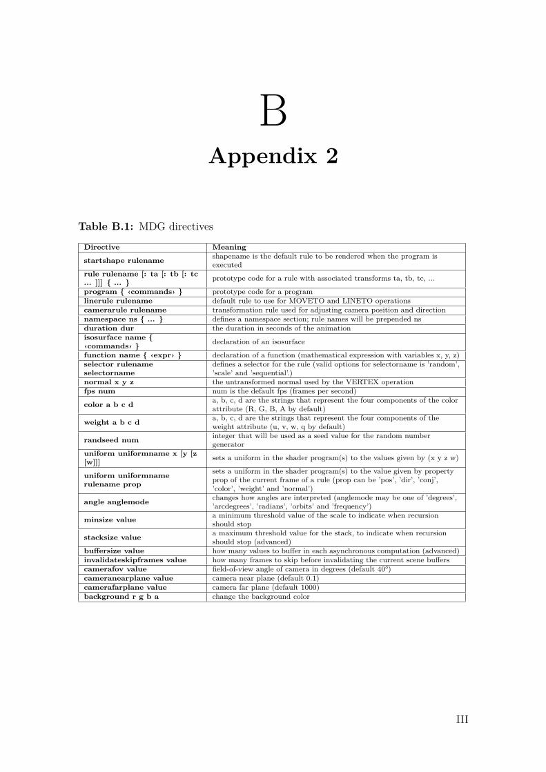
B Appendix 2 III
C Appendix 3 VII
x
List of Figures
2.1 Artwork generated with Context Free. . . . . . . . . . . . . . . . . . 7
4.1 Model generated through probabilistic selection of rules. . . . . . . . 224.2 Different techniques for creating smooth joints. . . . . . . . . . . . . . 254.3 Demonstration of a model created with composite transform rules.
Each transform represents a rotation around the path of the parenttransform. See code in C.3. . . . . . . . . . . . . . . . . . . . . . . . 28
5.1 Sphereflake model, rendered using continuous LOD. . . . . . . . . . . 305.2 There is a straight-forward conversion between the syntax of L-systems
and the MDG grammars. By selecting rules based on recursion depth,we will achieve the same effect as an L-system, but without the needto first construct a symbolic string representation. . . . . . . . . . . 31
5.3 One domain, where compact descriptions of models is essential, iswithin the field of nanoscale molecular science. . . . . . . . . . . . . . 32
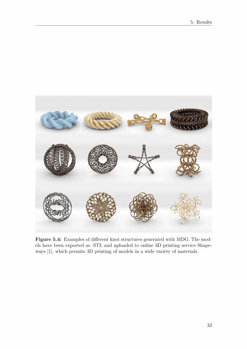
5.4 Examples of different knot structures generated with MDG. The mod-els have been exported as .STL and uploaded to online 3D printingservice Shapeways [1], which permits 3D printing of models in a widevariety of materials. . . . . . . . . . . . . . . . . . . . . . . . . . . . . 33
xi

List of Figures
xii

1Introduction
This thesis will present a novel approach to procedural shape synthesis based on theuse of quaternions and shape grammars. We will examine previous work within threeseemingly distinct fields — shape grammars, quaternions and procedural modeling— and we will show how these fields can be used in conjunction to provide a powerfulsyntactic tool for describing a wide variety of 3D objects.The main contribution of this report will be to highlight why quaternions is a usefultool in the context of procedural modeling and why our implementation of shapegrammars, which we have chosen to term Model Design Grammars (MDG), providea compact representation of such models.Moreover, we will look at the theory of rotations and reflections and we will demon-strate how rigid transformations can be used to build complex geometrical structuresfrom a set of predefined rules.We will look at how common techniques used in modeling, such as extrusions andsurface revolutions can be easily constructed by combining special profile rules withcurve sweeping operations. Additionally, we will examine how to efficiently evaluategrammar rules and what selection criteria to use for our rule selection. We willstudy the topic of skeletal animation and we will show how quaternions can be usedto describe the compound transformations of hierarchical skeletons.
1.1 MotivationProcedural modeling is a common technique employed by both animators and de-signers when constructing three-dimensional objects. Oftentimes, the proceduralgenerator has been hardcoded within the modeling software itself and is exposedonly as a set of adjustable parameters for the designer. This thesis emphasizes adifferent approach, where the designer needs to provide a syntactic description of themodel, before it is generated. This approach gives a greater freedom in representinga large variety of objects. This approach also encourages a scientific understandingof geometry, where the designer can explore many different shapes and geometries,by making small adjustments to the model descriptions.There are many different scientific fields that would benefit from a compact syntac-tical representation of procedural models. In physics, chemistry and biology, it isof great interest to be able to find different representations of molecular structuresand crystal lattice models. In architecture, it is essential to be able to explore newdesigns and to be able to represent symmetries and geometries in a simple way [32].Mathematical descriptions of geometry often provide a great aesthetic value, and
1

1. Introduction
this is can be used for more efficient development of designs in the jewelry industry,where conventional modelmaking is often a major bottleneck [48].Computer games could benefit from procedural models for the same reasons as anyof the above fields, but here we also have the additional benefit of being able to savedisk space by representing complex geometries with simple formulas.The most common way to represent transformations in Euclidean space is probablyby using transform matrices. What are quaternions and why would we want to usethem? There are many reasons why quaternions may be a better representationthan matrices. The following is a list of some of the benefits of using quaternions(the list is partially extracted from the book Visualizing Quaternions by Andrew JHanson [21]):
Shape A unit quaternion represents a point on the hypersphere SO(3).
Metric Provides a meaningful metric to compare and understand different orien-tations.
Interpolability It is possible to perform smooth interpolation between two orien-tations.
Gimbal lock Quaternions avoid the problem of gimbal lock that is present withEuler angles.
Memory A quaterion can represent a rotation using only 4 numbers, whereas a3× 3 rotation matrix requires 9 numbers.
Spinors Unlike rotation matrices, quaternions provide a way to represent spinors,making it possible to distinguish between 360◦ and a 720◦ rotations.
1.2 Problem statementThe thesis project was conceived from a few independent observations made by theauthor:
• Shape grammars is a powerful syntactic tool for representing many differentgeometries1.
• With the notable exception of L-systems, there is little research on other typesof shape grammars for procedural modeling in R3 space.
• Recursive evaluation of production rules gives additional expressive power thatis not available in other modeling languages.
Designing a new shape grammar will involve finding an answer to a few substantialquestions:
• What modifications and additions would make this grammar different fromshape grammars in R2 space, such as CFDG?
1This observation was made by studying shape grammars for representing two-dimensionalvector objects, see e.g. [15]
2

1. Introduction
• What set of geometric transformations would be useful in R3 space?
• What would be a suitable representation for vertices and normals?
• Could shape grammars be used to describe camera paths and compound trans-formations?
• Could shape grammars provide a language for animation?
• What criteria would be used for rule selection and for terminating recursions?
3

1. Introduction
4

2Previous Work
2.1 Grammars and modeling languagesNoam Chomsky is often credited as the father of modern linguistics. He was apioneer in the theory of syntax and in the classification of formal grammars [10, 11].Chomsky classified different grammars according to their expressive power. ContextFree Grammars (CFG) was one of the formal grammars described by Chomsky.These grammars have also been important in the development of procedural shapesynthesis, where they can be used to describe a large number of procedural objects.
2.1.1 Turtle graphicsSeymour Papert developed the LOGO programming language in 1967 [17] and healso invented the notion of a moving turtle that would change location and orien-tation through a set of commands. The FORWARD and BACKWARD commands wouldadvance the turtle a number of units, optionally leaving a trail behind it. The LEFT
and RIGHT commands would change the orientation by a specified angle. Papertproposed turtle graphics as a tool within education to teach young children aboutmathematics [35].
2.1.2 Lindenmayer systemsL-systems and parallel rewriting grammars (PRG) were introduced by Lindenmayerin 1968 [26]. These systems provided a simple formalism for constructing visuallycomplex imagery of biologically developing systems and plant-like organisms [38].0L-systems represent the most basic instances of L-systems, where production rulesapply to each symbol independently of its neighbors in the symbol string. Thissystem is said to be context-free, since the selection process does not depend onthe context. A 2L-system1 will take into account the symbol before and the symbolafter each symbol and use that as a condition for rule expansion. This system canthen be said to be context-sensitive.The final output of an L-system is a string of symbols, that is later evaluated ina separate pass to build the procedural model. With bracketed L-systems, bracketparentheses are used to denote that the current transform space should be pushedor popped from a stack. This means that it is possible to return to a prior state by
1A 1L-system will use only one more symbol as a condition – either to the left or to the rightof the current symbol.
5
2. Previous Work
encapsulating a subtree within brackets. The tree-like fractals generated by thesesystems are sometimes referred to as graftals [45].Przemyslaw Prusinkiewicz has been a major contributor in the research about L-systems [39, 40, 8]. His research about self-organizing growth processes of trees [34]demonstrates how L-systems can be used to achieve a high level of realism. TheTreeSketch system [27], one application of this research, explores the concept ofusing a procedural brush for drawing trees.
2.1.3 Shape grammarsJames Gips and George Stiny are generally credited as having introduced the conceptof shape grammars in 1971 [47, 18, 19]. Shape grammars built upon the grammardefinitions investigated by Chomsky and added a set of rules for substituting symbolswith a shape. The grammars presented by the authors were very closely related toL-systems, in terms of representing transforms and shapes as strings of symbols.
2.1.4 GEOMEDAn early example of using computers for procedural modeling is the GEOMED soft-ware, developed by Bruce Baumgart in 1974 [6, 7]. GEOMED provided a compactnotation for many complex geometric objects, including polyhedra. It supported fea-tures such as curve sweeps along a path using a profile curve and advanced geometrictransformations. While the software was interactive, updating a push-down stackwhen commands were entered, the notation of these commands formed a modelinglanguage that could probably be classified as a shape grammar. Baumgart hardlycited any references in his papers, which makes it difficult to tell what were the maininfluences of his work (possibly because this was also part of a classified ARPA re-search program.) Unmistakingly, this work was highly original and even by today’sstandards it is interesting to look at some of the aspects of his implementation.
2.1.5 ASASAn important contribution in the domain of modeling languages is the Actor/Scrip-tor Animation System (ASAS), introduced by Craig Reynold in 1982 [42]. ASASwas implemented in LISP and was inspired by partly by formal natural language de-scribed by Terry Winograd [49]. There were several generations of the ASAS systemand it was developed into a very versatile tool for both modeling and animation (itwas also used in many TV productions.) Reynolds did not explicitly make any ref-erences to shape grammars, but the language should definitely be considered one ofthe precursors to MDG in that it allowed similar recursive definitions of transforms.
2.1.6 GENMODSnyder et al. rigorously define the mathematical framework needed for generativemodeling [46]. The authors examine concepts such as generators and manifolds.Advanced methods for curve sweeping are investigated, where curves are used as
6
2. Previous Work
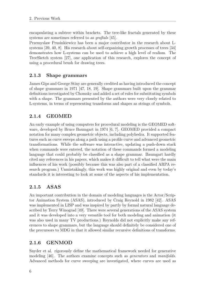
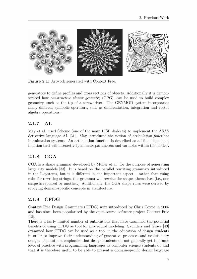
Figure 2.1: Artwork generated with Context Free.
generators to define profiles and cross sections of objects. Additionally it is demon-strated how constructive planar geometry (CPG), can be used to build complexgeometry, such as the tip of a screwdriver. The GENMOD system incorporatesmany different symbolic operators, such as differentiation, integration and vectoralgebra operations.
2.1.7 ALMay et al. used Scheme (one of the main LISP dialects) to implement the ASASderivative language AL [31]. May introduced the notion of articulation functionsin animation systems. An articulation function is described as a “time-dependentfunction that will interactively animate parameters and variables within the model”.
2.1.8 CGACGA is a shape grammar developed by Müller et al. for the purpose of generatinglarge city models [33]. It is based on the parallel rewriting grammars introducedin the L-systems, but it is different in one important aspect – rather than usingrules for rewriting strings, this grammar will rewrite the shapes themselves (i.e., oneshape is replaced by another.) Additionally, the CGA shape rules were derived bystudying domain-specific concepts in architecture.
2.1.9 CFDGContext Free Design Grammars (CFDG) were introduced by Chris Coyne in 2005and has since been popularized by the open-source software project Context Free[15].There is a fairly limited number of publications that have examined the potentialbenefits of using CFDG as tool for procedural modeling. Saunders and Grace [43]examined how CFDG can be used as a tool in the education of design studentsin order to improve their understanding of generative processes and evolutionarydesign. The authors emphasize that design students do not generally get the samelevel of practice with programming languages as computer science students do andthat it is therefore useful to be able to present a domain-specific design language
7
2. Previous Work
that does not add too many new concepts and abstractions. An engine for creatingCFDG grammars using genetic algorithms was implemented in Processing2.Machado and Nunes [28, 29] investigated how CFDG could be used as a tool for evo-lutionary art, where genetic algorithms would transform a set of different grammarsusing mutation and crossover operators.
2.1.10 StructureSynthStructureSynth, a software developed by Mikael Christensen in 2009 [13, 12], incor-porates a CFDG derivative language for threee-dimensional modeling that is prob-ably the closest relative to the MDG modeling language. The author introducesthe notion of rule retirement and substitutions, which is similar to the rule selectionmechanisms using recursion depth presented in this thesis.Christensen also highlights the benefits of using CFDG-based systems for con-strained systems and generative art. Design grammars are restricted in what kind ofobjects they are able to encode, unlike most procedural languages and hence thereis a constrained exploration space that can be exploited in order to construct newmodels by making small alternations to the grammars and to the model parameters.
2.1.11 FuguFugu is a modeling system based on the Lua scripting language [37]. The implemen-tation can be used for modeling, manipulation and animation and it is capable ofgenerating complex organic models. The system encourages both rapid prototypingand experimentation through a set of flexible 3D mesh operations.
2.2 QuaternionsQuaternions were conceived by William Rowan Hamilton already in 1843 [20].Hamilton was a strong proponent of using quaternions as the standard algebraicentity to encode vectors in Euclidean R3 space and for describing their algebraicoperations [21]. In fact, vector algebra operations, such as the cross product andthe dot product were discovered only after analyzing the properties of quaternions.Perhaps the most important quaternion property, namely that of representing orien-tations in R3 space, was demonstrated by Hamilton’s contemporary, Arthur Cayley,in 1845 [9].Clifford algebras provide a generalization of geometrical transformations in Eu-clidean Rn space, in which quaternions constitute a special case for n = 3 [5, 23].H.S.M. Coxeter observed that a quaternion rotation can in fact be represented asthe product of two reflections [14].Shoemake offers a strong argument for using quaternions for camera trajectoriesin computer animation [44]. Why do so many use Euler angles, despite their manydisadvantages? Shoemake argues that this is due to quaternions being a subject thatis generally introduced after the mathematics of Euler angles in higher education.
2Processing is a software tailored specifically for education within media arts [41].
8

2. Previous Work
The use of splining quaternions in keyframe animation systems has also been studiedby Duff [16] and by Pletinckx [36].A major application area for quaternions is within the aerospace industry, where ithas been used in satellite navigation systems for many years [25].Some recent developments within the fields of visualization and quaternions is theuse of quaternion maps for representing orientation frames within protein molecularstructures [22]. Quaternions also provide a useful similarity metric for comparisonof protein structures.
9

2. Previous Work
10
3Theory
We present a theoretical basis for understanding the concepts of our implementation.We will be concerned mostly with the aspects of transformations in Euclidean R3
space. The mathematical component for representing transformations in our imple-mentation is quaternions. This is one alternative that provides certain advantagesand disadvantages compared to other representations.
3.1 Grammars
3.1.1 Context-free grammars
Chomsky defined a context-free grammar as a 4-tuple (V,Σ, R, S), where
1. V is a set of non-terminal symbols,
2. Σ is a set of terminal symbols,
3. R is a set of production rules that map from V to (V ∪ Σ),
4. S is the initial symbol.
5. a grammar G generates a language L1.
Each production rule is defined as a symbol v ∈ V that maps to a string of symbolss1, . . . , sn, such that sk ∈ (V ∪ Σ),∀sk.Both CFDG and the 0L-systems are examples of context free languages. The pro-duction rules are derived from exactly one non-terminal symbol. The so calledIL-systems are context-sensitive, since a production rule is subject to the condi-tion of neighboring symbols in the input string. MDG is a completely context-freelanguage, meaning that any production rule can map only from one non-terminalsymbol. However, MDG also includes the notion of conflicting rules, such that thereare multiple production rules that maps from the same non-terminal. This is infact one of the central aspects of this language, and it allows us to implement veryspecific rule selection mechanisms.
1A language L is said to be context-free, if there exists a G such that L = L(G).
11
3. Theory
3.2 RotationsA few common ways of representing rotations and orientations are outlined. This isan essential component in rigid body dynamics, where the orientation will determinethe motion of a rigid body.
3.2.1 Euler anglesProbably one of the most intuitive ways of representing rotations, in Euclideangeometry, is through the use of Euler angles. Three angles, α, β and γ are used todenote the rotation about three different axes.Additionally, there is a distinction between classic Euler angles and Tait-Bryan orCardan angles2. It is important to realize that for Euclidean geometries in R3 orhigher, rotations are not commutative and it makes a difference in which order yourotate about the axes.
3.2.2 Axis-angleAnother convenient way to represent rotations, is through the axis-angle represen-tation, which consists of a vector a and a rotation θ about the same vector:
(axis, angle) =
axayaz
, θ (3.1)
3.2.3 MatricesMatrices is a common way of representing rotations in computer graphics.We can use separate matrices in order to describe a rotation around each axis in R3:
R(φ, θ, ψ) =
1 0 00 cosφ − sinφ0 sinφ cosφ
︸ ︷︷ ︸
Rx(φ)
·
cos θ 0 sin θ0 1 0
− sin θ 0 cos θ
︸ ︷︷ ︸
Ry(θ)
·
cosψ − sinψ 0sinψ cosψ 0
0 0 1
︸ ︷︷ ︸
Rz(ψ)
(3.2)
Here φ, θ and ψ corresponds to the Tait-Bryan angle representation of a rotation.Similarly, Euler angles may be used, by replacing the third rotation matrix withRx(ψ).
3.2.4 QuaternionsIn quaternion algebra, the vector v is rotated by the quaterion q through the formula
v′ = qvq∗. (3.3)2Classic Euler angles refers to angles where α and γ represents a rotation about the same axis,
while Tait-Bryan or Cardan angles refers to rotations about three distinct axes (also the samething as yaw, pitch and roll.)
12
3. Theory
3.3 QuaternionsWe define a quaternion q as a 4-tuple (qx, qy, qz, qw) with the following properties:
q = (qx, qy, qz, qw) = iqx + jqy + kqz + qw (3.4)i2 = j2 = k2 = −1, jk = −kj = −i, ki = −ik = j, ij = −ji = k. (3.5)
It is usually convenient to divide the quaternion into its vector part qv and its scalarpart qw:
qv = (qx, qy, qw) = iqx + jqy + kqz (3.6)q = (qv, qw) = iqx + jqy + kqz + qw = qv + qw (3.7)
Multiplication between two quaternions q and r is defined as:
qr =(iqx + jqy + kqz + qz)(irx + jry + krz + rw)=i(qzrz − qzry + rwqx + qwrx)
+ j(qzrx − qxrz + rwqy + qwry)+ k(qxry − qyrx + rwqz + qwrz)+ qwrw − qxrx − qyry − qzrz
=(qv × rv + rwqv + qwrv, qwrw − qv · rv)
(3.8)
We define the quaternion conjugate as
q∗ = (qv, qw)∗ = (−qv, qw) = (−qx,−qy,−qz, qw), (3.9)
and the quaternion norm as
N(q) = qq∗ = q∗q = qv · qv + q2w = q2
x + q2y + q2
z + q2w. (3.10)
For every quaternion, there exists a corresponding unit quaternion, also called aversor:
U(q) = q√N(q)
(3.11)
A pure quaternion is defined as a quaternion where qw = 0. These will satisfy therelations q∗ = −q and q2 = N(q)q. A point p = (px, py, pz) in Euclidean space R3,may be represented as a pure quaternion quaternion p = (p, 0) = (px, py, pz, 0).
3.3.1 Combining transformationsThis section demonstrates how quaternion reflection, rotation and scaling transfor-mations are combined (similarly to how multiple affine transformations are combinedwith rotation matrices.)A unit quaternion q will rotate a point x through the formula
R(x,q) = qxq∗. (3.12)
13
3. Theory
Let us consider the same function R(x,q), defined for any quaternions (i.e. bothunit and non-unit quaternions):
R(x,q) = qxq∗ (3.13)
R(x,q) =√
N(q)U(q)x√
N(q∗)U(q∗) (3.14)
R(x,q) =√
N(q)√
N(q∗)U(q)xU(q∗) (3.15)R(x,q) = N(q)U(q)xU(q∗) (3.16)R(x,q) = N(q)R(x,q) (3.17)
Hence, the transformation R(x,q), represents a rotation of the vector x by U(q),and a scaling by the norm N(q). Rather than discarding the information aboutscale, by using only unit quaternions, this may be used as an additional parameterin the transformation.A series of rotations represented by q1,q2 . . . ,qn, can be represented using a singlecomposite quaternion q:
R(x,q1,q2 . . . ,qn) = q1q2 · · ·qnxq∗nq∗n−1 · · ·q∗1 = qxq∗ (3.18)
Similarly, a series of reflections can be represented in the same way:
F(x,q1,q2 . . . ,qn) = q1q2 · · ·qnxqnqn−1 · · ·q1 = qxq (3.19)
What is the general quaternion transformation that combines both rotations, reflec-tions and scaling transformations? Consider the composite function Ψ,
Ψ(x,q1,q2 . . . ,qn) = Ψ1(Ψ2(. . .Ψn(x,qn) . . .),q2),q1), (3.20)
where
Ψk(x,q) = ΨLk (q)xΨR
k (q) =
F(x,q) if reflectionR(x,q) if rotation
(3.21)
with
ΨLk (q) = q, for both rotations and reflections, (3.22)
and ΨRk (q) =
q for reflections,q∗ for rotations.
(3.23)
The formula can further be written as
Ψ(x,q1,q2 . . . ,qn) = ΨL1 (q1) · · ·ΨL
k (qn)xΨRk (qn) · · ·ΨR
k (q1) = qLxqR (3.24)
with qL and qR being the composite left and right side quaternions describing thegeneral transformation of rotation, reflection and scaling.
14
3. Theory
3.3.2 Relation to other representationsQuaternions are conveniently converted into any other representation of rotations.Sometimes a different representation is a better option for a specific domain, suchas shaders, where optimized matrix algebra routines can provide some advantagescompared to quaternions. Rotation matrices also simplify the operations of non-uniform scaling and skewing.
3.3.2.1 Rotation matrices
Conversion of a quaternion (qx, qy, qz, qw) into a 3× 3 affine matrix:1− 2q2y − 2q2
z 2qxqy − 2qzqw 2qxqz + 2qyqw2qxqy + 2qzqw 1− 2q2
x − 2q2z 2qyz − 2qxqw
2qxqz − 2qyqw 2qyqz + 2qxqw 1− 2q2x − 2q2
y
(3.25)
A similar method for converting back to quaternions is described by Akenine-Mölleret al. in [3].
3.3.2.2 Axis-angle
A quaternion is easily obtained from the axis-angle representation:
(qv, qw) =(
sin(θ
2
)v, cos
(θ
2
))(3.26)
The inverse operation (for qw 6= 1):
(v, θ) = qv√
1− q2w
, 2 arccos(qw) (3.27)
3.3.2.3 Euler angles
Euler angles to quaternion conversion is straight-forward:
qφ,θ,ψ =
cos(ψ/2) cos(θ/2) sin(φ/2) − sin(ψ/2) sin(θ/2) cos(φ/2)cos(ψ/2) sin(θ/2) cos(φ/2) + sin(ψ/2) cos(θ/2) sin(φ/2)sin(ψ/2) cos(θ/2) cos(φ/2) − cos(ψ/2) sin(θ/2) sin(φ/2)cos(ψ/2) cos(θ/2) cos(φ/2) + sin(ψ/2) sin(θ/2) sin(φ/2)
(3.28)
3.3.3 Obtaining the rotation from two vectorsSuppose u and v are two known vectors and that v = quq∗ (i.e., v is the vector urotated by the quaternion q.)In this case, it can be shown that
(qv, qw) =(
u× v,u · v√
N(u)N(v))
(3.29)
15

3. Theory
16

4Implementation
This chapter will detail the specifics of the implementation of MDG. Moreover,this chapter will cover the syntactical framework used for the implementation ofthe language itself. It will also cover the methods used for evaluating an MDGgrammar in order to synthesize a shape (any procedural model represented in theMDG language, is considered to be a grammar in itself.) Finally, we will dissect thetopic of compound transformations and animation.
4.1 Syntax and semanticsIn this section we present the syntactical elements that are needed to understandMDG. A reference of the grammar that is used by the MDG parser can be found inA.1. Additionally a description of the different language elements is provided in B.
4.1.1 DirectivesAt the most basic level, an MDG model is defined by a set of global directives, suchas RULE, STARTSHAPE and BACKGROUND. The definition of an MDG grammar consistsof one or more RULE declarations.Support for isosurfaces has been implemented through the ISOSURFACE directive,which generates a mesh model from evaluating a mathematical function on a 3Dvoxel grid, with an explicitly defined bounding box1.Additionally, some directives are used to control global variables, such as BACKGROUND,WEIGHT, CAMERAFOV, MINSIZE and MAXDEPTH.A few directives are related to the shading system. The PROGRAM directive allows usto control the rendering process of the graphics pipeline, by specifying vertex andfragment shaders. It supports rendering in several passes as well as rendering toan off-screen texture. The UNIFORM directive allows us to set the values of specificuniform variables in the shaders (such as the position of light source.)
4.1.2 Production rulesProduction rules are declared according to the pattern where WEIGHT is a value usedas a metric for rule selection. A rule may have multiple declarations, such that therewould be a conflict in name resolution in most procedural programming languages.
1Isosurfaces are generated by the use of an Open Source implementation of the marching cubesalgorithm by Aaron Hochwimmer.
17
4. Implementation
rule RULENAME WEIGHT {
RULEBODY
}
MDG will handle such a conflict according to a rule selection process that dependson the weight of each conflicting rule.The RULEBODY is a list of either iterators or references to other production rules thatwill be evaluated sequentially when this rule is executed.The STARTSHAPE directive is used to determine which rule will be evaluated first.In addition to explicitly defined production rules, there are some built-in implicitrules.
4.1.3 DrawablesWhile a production rule can represent both a terminal and a non-terminal, MDGalso provides a few built-in terminal rules, which have been termed drawables:
• The VERTEX drawable will emit a vertex, transformed by the current transformspace. This will also include information about the current normal vector.Every three vertices will be interpreted as a triangle by the rendering system.
• The MOVETO and LINETO drawables, will connect two vertices by using a separateprofile rule, defined by the LINERULE directive.
• The RESET drawable will reset the transform space to the last coordinate andorientation of either MOVETO or LINETO.
• The ISOSURFACE command defines new drawables that are generated by eval-uating a parametric function in R3-space.
MDG uses a modular approach for drawables, where new drawables can be registereddynamically. Possible extensions would be to import objects from different 3D fileformats.
4.1.4 NamespacesRules may be logically grouped into different namespaces, using the NAMESPACE di-rective. Namespaces are particularly useful when using the MOVETO and LINETO com-mands (see Section 4.3.) Each namespace will maintain its own buffer for thesecommands, which allows us to have multiple lines that are connected using separatecoordinates. It is possible to reference a namespace that has not been declared (e.g.X.LINETO) and it will remember the last coordinate in this particular namespace.This could also be used as a mechanism for reading back rotation and coordinateinformation at higher recursion levels, if combined with the continuation operator(see Section 4.2.4.)
18
4. Implementation
4.1.5 AdjustmentsOne of the main differences between L-Systems and CFDG-based systems, is thatCFDG encodes transformations within the production rules themselves (rather likemany procedural languages.)The following example will perform a rotation of 20◦ around the x-axis and 30◦around the y-axis, moving 10 units along the z-axis and flipping across the z-plane,while simultaneously adding 0.2 and 0.3 to the color parameters R and G:
rule X{
Y {rx 20 ry 30 z 10 fz R 0.2 G 0.3}
}
4.1.6 IteratorsCFDG provides an intuitive method for iteration. Loops have a similar structureas in many procedural languages, but the code does not include a loop index. Thefollowing rule will perform 10 iterations, rotating 5◦ around the x-axis and moving3 units along the z-axis in each iteration:
rule X {
10 * { rx 5 z 3 } Y {}
}
These kind of constructs have not been studied in great detail in other shape gram-mars. Parametric L-systems permit the use of parameter values associated witheach symbol. Such parameters allows a kind of controlled expansion, where termi-nal rules can be associated with a parametric value. However, this is not the same asiteration, since it requires that all symbols in the output string are rewritten beforethe next parametrically controlled expansion step.A special construct was added to the syntax of iterators that we term divisors.Instead of specifying only the number of iterations m, the iterations can also bespecified as m/n, where n is a number that divides the transformation into n smallersteps.
4.1.7 MacrosA macro preprocessor was implemented. The preprocessor supports several usefuldirectives:
@IMPORT directive for including other MDG projects;@FRAGMENTSHADER and @VERTEXSHADER directives for defining shaders;@DEFINE, @IFDEF, @ELSE, @ENDIF for conditional parsing;@MACRO defines a macro and allows parametric expansions;@EXPAND expands a previously defined macro;@PRESETS defines presets that can be accessed in the user interface;
19

4. Implementation
@PARAM parameter value associated with a preset (int, float or bool.)The system fully supports the use of custom shaders. There are many reasons not touse a static shader in a procedural modeling language. Shader design is a whole re-search field in its own and by combining this with a solution for procedural modeling,we get a solution with maximum flexibility in terms of visualization options.
4.2 EvaluationOur production rules are compiled into a derivation tree that can be evaluated eitherthrough depth-first or breadth-first traversal.Other CFDG-based implementations, such as Context Free and StructureSynth usea breadth-first evaluation. This has some advantages, but it will not give the sameresults if we use some of the novel constructs that are introduced in this section,such as continuation and sequential selection.
4.2.1 TransformsFor each rule in the grammar, we precompute a composite transformation, repre-senting translation, scaling, reflection and rotation.Each expression of adjustments, maintains a compact internal representation of thetransformations needed to be carried out. Rather than computing every transfor-mation in the evaluation pass of the syntax tree, a composite transformation isprecomputed for each transform expression. This representation will respect theorder of the all of the transformations (scaling, translation, rotation, reflection androtation), and it will be represented by three distinct quaternions q, q and u.
4.2.1.1 Internal representation of transforms
The internal representation of transforms requires that we maintain a set of threequaternions for each transform expression and for each stack frame. The quaternionsassociated with a transform expression are computed from the transform expressionaccording to the procedure outlined below.
Initialization of variables:
u0 = 0 (translation) (4.1)q0 = q0 = 1 (orientation) (4.2)
Translation by v:
uk+1 = uk + qkvqk (4.3)
Rotation by r:
qk+1 = qkr (4.4)qk+1 = r∗qk (4.5)
20
4. Implementation
Reflection by r:
qk+1 = qkr (4.6)qk+1 = rqk (4.7)
Scaling by a scalar s:
qk+1 = sqk (4.8)qk+1 = sqk (4.9)
The evaluation process is similar. We initialize our variables:
p0 = 0 (translation) (4.10)w0 = w0 = 1 (orientation) (4.11)
When a rule is invoked , the precomputed transform is applied as follows:
pk+1 = pk + wkuwk (4.12)wk+1 = wkq (4.13)wk+1 = qwk (4.14)
Note that these are all the computations that are needed in order to perform all ofthe transformations in each adjustment formula. No extra step is needed for scaling– it is implicit in the multiplication by the (non-unit) quaternions.Note that any value could be chosen for the initialization of pw. The quaternionvectors sent to the vertex shader will be multiplied by the projection matrix andthen it is necessary to set pw = 1 for uniform scaling. However, pw could alsoserve as an additional parameter for controlling the the scale of our model, since ineffect, the coordinates will be mapped to (x/w, y/w, z/w) after multiplication witha projection matrix.
4.2.2 Rule selectionOne of the main ideas of CFDG, and consequently, of MDG, is that it permitsmultiple conflicting production rules. When a rule that has been declared multipletimes is evaluated, only one of its definitions is selected. This does not violate theprinciple of the corresponding grammars being context-free.CFDG resorts exclusively to a stochastic selection process, whereas MDG supportsseveral different alternatives for selection. This is also a feature that provides sig-nificant advantages to L-systems, which have limited capabilities in terms of ruleselection (although parametric, stochastic and context-sensitive L-Systems providesome mechanisms for rule selection.)
4.2.2.1 Probabilistic selection
MDG inherits the default stochastic method for rule selection that is also found inCFDG. The weight value associated with a rule denotes the probability that thisrule will be selected.
21
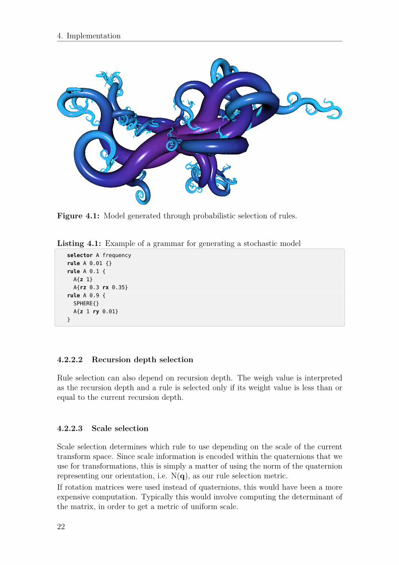
4. Implementation
Figure 4.1: Model generated through probabilistic selection of rules.
Listing 4.1: Example of a grammar for generating a stochastic model� �selector A frequency
rule A 0.01 {}
rule A 0.1 {
A{z 1}
A{rz 0.3 rx 0.35}
rule A 0.9 {
SPHERE{}
A{z 1 ry 0.01}
}� �
4.2.2.2 Recursion depth selection
Rule selection can also depend on recursion depth. The weigh value is interpretedas the recursion depth and a rule is selected only if its weight value is less than orequal to the current recursion depth.
4.2.2.3 Scale selection
Scale selection determines which rule to use depending on the scale of the currenttransform space. Since scale information is encoded within the quaternions that weuse for transformations, this is simply a matter of using the norm of the quaternionrepresenting our orientation, i.e. N(q), as our rule selection metric.If rotation matrices were used instead of quaternions, this would have been a moreexpensive computation. Typically this would involve computing the determinant ofthe matrix, in order to get a metric of uniform scale.
22

4. Implementation
4.2.2.4 Functional selection
Rule selection can be made by evaluating a custom multivariate function f : Rn → R.In our current implementation this function can be a custom expression of ourcurrent position, but this could also be extended to include other parameters, suchas the current orientation, or any other custom parameters that are passed on thestack in the evaluation (similarly to conditions in parametric L-systems.)
4.2.2.5 Sequential selection
Sequential selection provides an ordered deterministic approach to rule selection.Each rule will be executed sequentially n times, where n is the rule weight. Notethat this kind of scheme will cause different results depending on whether depth-firstor breadth-first evaluation is used.
4.2.3 Termination criteriaFrom the previous section, it should be evident that we may terminate a recursionby using a suitable selection criteria.However, it is also useful to have some default criteria for implicit termination. Twosuch criteria have been implemented: Evaluation may stop after a specified numberof recursions, through the maxdepth directive. It may also stop when the scale of thecurrent transform becomes sufficiently small, by using the minsize directive. Thiscorresponds to depth selection and scale selection when using explicit rule selection.
4.2.4 ContinuationEach rule will evaluate each of the production rules defined within its body. Thisforms parent-child relationship between productions. The child rule automaticallyinherits the transform space of its parent rule (transformed by any intermediateadjustment expressions.) When the next rule is evaluated, again it will be relativelyto the parent transform space.However, sometimes it is desirable to actually use the transform space of the pre-ceding rule within the rule body. This concept is denoted continuation, since wewill continue from where the last rule last updated the transform space (possibly ata completely different recursion depth.)Below is shown an excerpt from the code used to generate an SiC crystallographicstructure (see C.4 for the complete model):
rule ABCB {
SiC {} \ // A
SiC {} \ // B
SiC {fx} \ // C (flip x axis)
SiC {} \ // B
MOVETO{fx} // (flip x axis -- for the next ABCB)
}
Each invocation of the SiC rule will adjust the translation of the transform space.By using continuation, we will place the next SiC molecule such that it connects toits neighbor and forms a crystallographic structure. Finally, we use MOVETO in order
23

4. Implementation
to update the transform space through reflection of the yz-plane, so that the nextABCB layer will be correctly transformed.
4.3 Curve sweepingTechniques for performing curve sweeps were implemented. A line is constructed byextruding a profile curve, defined by the LINERULE command, along a trajectory ora motion path.A generalized cylinder is constructed for every line segment that is defined with theMOVETO and LINETO commands2. When LINETO is called an extrusion is constructedfrom the coordinate saved by the last MOVETO or LINETO command. The extrusionconnects the vertices of two profile curves with a triangle strip.The BLENDTO command was implemented as a special variant of LINETO that createsa smoothly interpolated path between the two vertices.
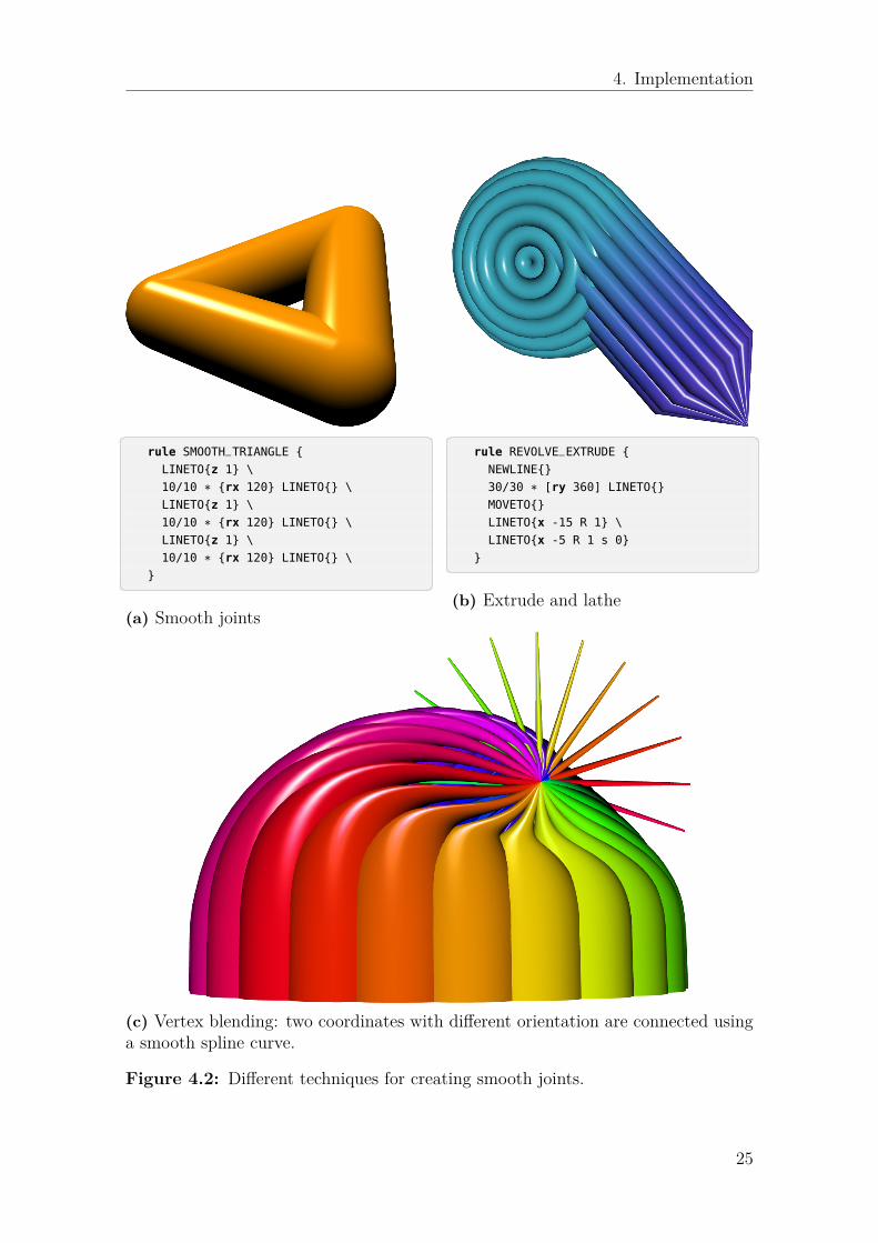
4.3.1 Smooth jointsA common problem in modeling is to connect two separate objects that are definedin two separate transform spaces, so that they join together smoothly. Considertwo different cylinders that are separated by some distance and oriented in differentdirections. We want to find an intermediate surface that connects one cylinder toanother. This problem exists not only in modeling, but also in animation, wheredifferent joints of a skeleton model need to be animated.One technique to address this problem is known as vertex blending or skinning.We know the shape of the surfaces that we want to connect (circles in the case ofcylinders) and we know the transforms that define their origin and orientation. Byinterpolating the two transform spaces using a weight, w ∈ [0, 1], we are able tocompute new vertices that form a smooth joint (our representation of a transformspace and our interpolation function, will determine the smoothness of the surface3.)
4.3.2 Spline interpolationQuaternions have been studied extensively for the purpose of interpolating orienta-tions along motion paths and trajectories. In animation systems this is sometimesreferred to as guiding. The spherical interpolation scheme investigated by Shoemake[44], shows how to perform interpolation such that the orientation changes with evensteps along the unit sphere. This scheme was combined with a Bezier spline inter-polation scheme for coordinates. Duff proposed another interpolation scheme basedon B-splines [16]. Yet another scheme was investigated by Pletinckx [36].The BLENDTO drawable was implemented in MDG in order to not only interpolateposition and orientation, but also to interpolate information about the scale. The
2These commands are meant to be 3D analogues of the same commands found in many 2Dcanvas libraries.
3It has been demonstrated that Dual Quaternions provide a better solution to this problemthan regular quaternions[24].
24
4. Implementation
� �rule SMOOTH_TRIANGLE {
LINETO{z 1} \
10/10 * {rx 120} LINETO{} \
LINETO{z 1} \
10/10 * {rx 120} LINETO{} \
LINETO{z 1} \
10/10 * {rx 120} LINETO{} \
}� �(a) Smooth joints
� �rule REVOLVE_EXTRUDE {
NEWLINE{}
30/30 * [ry 360] LINETO{}
MOVETO{}
LINETO{x -15 R 1} \
LINETO{x -5 R 1 s 0}
}� �(b) Extrude and lathe
(c) Vertex blending: two coordinates with different orientation are connected usinga smooth spline curve.
Figure 4.2: Different techniques for creating smooth joints.
25
4. Implementation
implementation assumes that the line is going to continue in the z-direction4 fromthe source coordinate and orientation pair (u1,q1) to the target coordinate andorientation (u2,q2). The implementation below was derived experimentally:
D =√
N(u1 − u2) · λ (4.15)
v1 = q1
(0, 0, D
N(q1) , 0)
q∗1 (4.16)
v2 = q2
(0, 0,− D
N(q2) , 0)
q∗2 (4.17)
The interpolated coordinate and orientation (u,q) is computed for the interpolantw ∈ [0, 1]:
s = SMOOTHSTEP(w) (4.18)u = LERP(LERP(u1,v1, s), LERP(u2,v2, s), w) (4.19)q = LERP(q1,q2, w) (4.20)
q = q
√√√√LERP(N(q1),N(q2), s)N(q) (4.21)
Figure 4.2c demonstrates the effect of using this technique with the parameter λ =0.75, when splining between different transform spaces.
4.3.3 Straight lines
The LINETO and BLENDTO commands connect two coordinates with different scale andorientation using curve sweeping along a line. The orientation at each coordinatedoes not necessarily need to correspond to the orientation of the line.However, sometimes it is desirable to make the extrusion orthogonal to the linesegment. The SLINETO command was added for this purpose. In order to find thequaternion that represents the orientation of our line, we need to use Equation 3.29.
4.4 Animation
Support for animation was included by observing that in a tree-like recursive repre-sentation of a model, each branch or each shape along the path could be an objectthat could be animated separately.By assigning an articulation function [31] to each bone, we are able to animate mul-tiple attributes, such as orientation, position and color. This has been implementedin a way that permits real-time animation of bones through the use of customizedvertex shaders.
4It is possible to use any direction as a convention.
26

4. Implementation
4.4.1 Animation framesThe concept of animation frames was introduced. In order to understand the im-plementation, we need to distinguish between model rules and transform rules. Atransform rule is a rule that will emit frames, while a model rule is a rule that willemit shapes or vertices.Each rule is associated with a number of transform rules. Animation is achievedthrough a number of different steps:
1. Evaluate the procedural model and construct a hierarchical bone structure,where each bone is a model rule with at least one associated transform rule;
2. Sample animation frames at time t for each bone in the generated model5;3. Build transform matrices used to animate each bone in the vertex shader6.
This step requires conversion from quaternions to matrices, but it will be doneonly once for each transform rule and it has not proven to be a performancebottleneck.
Listing 4.2: The shape generated by model rule A is associated with a number oftransform rules, X1, . . . , Xn.� �
rule A : X1 : X2 : ... : Xn {
... // generate our model
}
rule X1 {
// rotate 360 degrees around z axis and move 10 steps
// along x axis (emit 100 frames in total)
100 / 100 * {rz 360 x 10} FRAME{}
}
rule X2 {
FRAME{}
X2{z 0.1} // move 0.1 steps along z axis (infinite recursion)
}� �How do we rewind to an earlier frame, which has already been evaluated? Eachtransform rule maintains its own cache of sampled animation frames. Hence, rewind-ing the animation is simply a look-up process in the local cache of each transformrule.
4.4.2 Camera trajectoriesThe camera is assigned a rule of its own through the CAMERARULE directive. This ruledescribes a time-dependent trajectory for the motion and orientation of the camera.Model parameters can be used to animate certain properties of the camera, such asfield-of-view or look-at direction.
5Transform rules will emit a frame at a time interval specified by the fps parameter (which canbe changed globally and can also be modified individually for each rule by adjustment expressions.)
6We will maintain an index for every vertex that will determine which bone matrix to use inthe shader.
27
4. Implementation
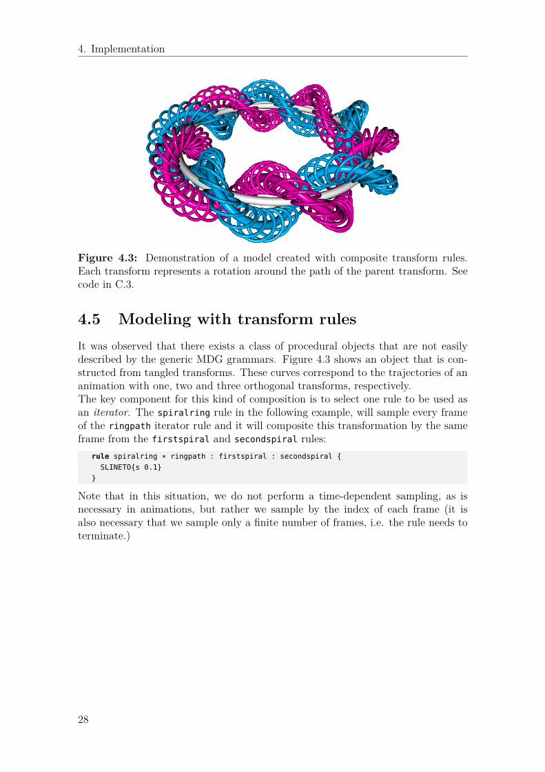
Figure 4.3: Demonstration of a model created with composite transform rules.Each transform represents a rotation around the path of the parent transform. Seecode in C.3.
4.5 Modeling with transform rulesIt was observed that there exists a class of procedural objects that are not easilydescribed by the generic MDG grammars. Figure 4.3 shows an object that is con-structed from tangled transforms. These curves correspond to the trajectories of ananimation with one, two and three orthogonal transforms, respectively.The key component for this kind of composition is to select one rule to be used asan iterator. The spiralring rule in the following example, will sample every frameof the ringpath iterator rule and it will composite this transformation by the sameframe from the firstspiral and secondspiral rules:
rule spiralring * ringpath : firstspiral : secondspiral {
SLINETO{s 0.1}
}
Note that in this situation, we do not perform a time-dependent sampling, as isnecessary in animations, but rather we sample by the index of each frame (it isalso necessary that we sample only a finite number of frames, i.e. the rule needs toterminate.)
28
5Results
A motivating factor in this thesis project has been to find a generic language forthe representation of a great number of geometric objects. Ideally, this should be alanguage that favors simplicity and that can easily be interpreted, even by a non-expert.MDG grammars provide a tool for modeling that not only can represent an objectin a concise way, but can also provide an insight about the geometry of the object athand. It is useful to think about geometries in terms of their descriptions in MDGand to use this as a method for exploration of new structures. In the context ofmolecular physics, you might want to ask “what are the different representations ofthis specific crystal lattice?” or “how can we describe its symmetries in terms of aset of transforms?” MDG grammars provide an answer that is usually meaningfulto the interpretation of these kind of physical or theoretical entities.This section will illustrate with a number of examples how MDG grammars can beused for many different applications, including molecular structures, fractals andpolyhedra.
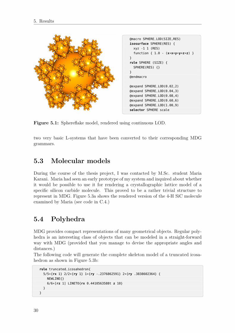
5.1 Level of detailMultiple approaches have been devised to adjust level-of-detail (LOD) when ren-dering complex scenes with many objects. The method known as continuous LOD,will adjust the complexity of a model according to some heuristic function (typicallydistance to the camera.) However, in our recursively evaluated grammars, we maywant to specify a different heuristics, such as the current scale of our transformspace. Figure 5.1 demonstrates how macros can solve the problem of LOD, whereeach expansion of a macro corresponds to an isosurface of a different resolution anda corresponding rule with a weight that is used as a metric for scale selection. Thesmallest spheres are represented as an octahedron with no more than eight vertices.
5.2 L-systemsOne of the questions that arose during the course of this thesis work was whetheror not L-systems can be represented in MDG. As we shall see, there is in fact astraight-forward conversion between 0L-systems and MDG grammars.This involves using depth selection to limit the recursion depth and continuation,to continue from the coordinate and transform of the last rule. Figure 5.2 shows
29
5. Results
� �@macro SPHERE_LOD(SIZE,RES)
isosurface SPHERE(RES) {
xyz -1 1 (RES)
function { 1.0 - (x*x+y*y+z*z) }
}
rule SPHERE (SIZE) {
SPHERE(RES) {}
}
@endmacro
@expand SPHERE_LOD(0.02,2)
@expand SPHERE_LOD(0.04,3)
@expand SPHERE_LOD(0.08,4)
@expand SPHERE_LOD(0.60,6)
@expand SPHERE_LOD(1.00,9)
selector SPHERE scale� �Figure 5.1: Sphereflake model, rendered using continuous LOD.
two very basic L-systems that have been converted to their corresponding MDGgrammars.
5.3 Molecular models
During the course of the thesis project, I was contacted by M.Sc. student MariaKarani. Maria had seen an early prototype of my system and inquired about whetherit would be possible to use it for rendering a crystallographic lattice model of aspecific silicon carbide molecule. This proved to be a rather trivial structure torepresent in MDG. Figure 5.3a shows the rendered version of the 4-H SiC moleculeexamined by Maria (see code in C.4.)
5.4 Polyhedra
MDG provides compact representations of many geometrical objects. Regular poly-hedra is an interesting class of objects that can be modeled in a straight-forwardway with MDG (provided that you manage to devise the appropriate angles anddistances.)The following code will generate the complete skeleton model of a truncated icosa-hedron as shown in Figure 5.3b:� �
rule truncated_icosahedron{
5/5*{rx 1} 2/2*{ry 1} 1*{ry -.2376862591} 2*{ry .3838602364} {
NEWLINE{}
6/6*[rz 1] LINETO{rx 0.4410563588t z 10}
}
}� �30

5. Results
� �n = 6, d = 4, δ = 60◦
YF
XF → YF+XF+YF
YF → XF-YF-XF� �(a) The Sirepinski arrowhead curve andits representation using L-system nota-tion. One of the models presented inPrusinkiewicz’s seminal paper [39].
� �n = 4, d = 5, δ = 60◦
XF
XF → XF+YF++YF-XF--XFXF-YF+
YF → -XF+YFYF++YF+XF--XF-YF� �(b) Peano-Gosper space-filling curve,originally named flowsnake. One of thefractals studied by Mandelbrot in 1977[30].
Figure 5.2: There is a straight-forward conversion between the syntax of L-systemsand the MDG grammars. By selecting rules based on recursion depth, we will achievethe same effect as an L-system, but without the need to first construct a symbolicstring representation.� �
startshape YF
selector XF, YF depth
rule XF 6 { YF{} \ XF{rx 60} \ YF{rx 60} }
rule YF 6 { XF{} \ YF{rx -60} \ XF{rx -60} }
rule XF 7 { SLINETO{z 1} }
rule YF 7 { SLINETO{z 1} }� �Listing 5.1: Equivalent Sirepinski arrowhead curve written in MDG. Note theuse of the continuation character in order to continue from the position andorientation of the last terminal rule.
31

5. Results
(a) 4-H SiC ABCB structure examined by MariaKarani, in her M.Sc. thesis.
(b) Model of a fullerenemolecule, also known as abuckeyball.
Figure 5.3: One domain, where compact descriptions of models is essential, iswithin the field of nanoscale molecular science.
The constants used in this code have been derived analytically, through the formulafor dihedral angles of an icosahedron:
a = 4r3 +√
5(5.1)
r = 1 ⇒ a0 = 0.7639320224 (5.2)r = 1/
√3 ⇒ a1 = 0.4410563588 (5.3)
arctan a0 + arctan 22π = 0.3838602364 (5.4)
14 −
3 arctan a0 + arctan 22π = −0.2376862591 (5.5)
5.5 KnotsSome experimenting with compound transforms resulted in an interesting family ofknot-like models, as shown in Figure 5.4. Despite the simple description of this model(see C.2), it lends itself to experimentation by adjusting the number of revolutionsabout each axis. It was also discovered that if the number of revolutions about eachaxis is denoted nx, ny, nz, then at least two of these numbers need to be co-prime inorder for the path to be connected.
32
5. Results
Figure 5.4: Examples of different knot structures generated with MDG. The mod-els have been exported as .STL and uploaded to online 3D printing service Shape-ways [1], which permits 3D printing of models in a wide variety of materials.
33

5. Results
34
6Discussion
While MDG has been inspired by CFDG, it has also been augmented with severallanguage features that are not part of the latter. The use of divisors in iteratedstatements has been very useful in that it provides an easy way to divide a sequenceof transformations into smaller steps. A common task in modeling is to performa rotation around an axis through a number of steps, which is simply a matter ofdividing by the number of iterations.Unlike CFDG, which performs a breadth-first traversal of the syntax tree, MDGperforms depth-first traversal. This requires less memory (and memory is more ex-pensive in 3D, due to the overhead of additional parameters passed on the stack.)The major drawback of depth-first evaluation is when the evaluation process is visu-alized in real-time, since it will show only sub-branches of the final model (considera tree that grows by one arm at a time, rather than all arms growing by a smallamount simultaneously.) Breadth-first evaluation might also be an advantage incontext-sensitive grammars, such as IL-systems, since the context should be sensi-tive to the current growth iteration. Probably MDG will never be able to supportthe kind of context-sensitive features described by IL-systems (since that actuallyrelies on the parallel rewriting paradigm.)There are also certain observations to be made about the use of transforms in MDG.Should a transform be implemented as a 3 × 3 matrix or as a quaternion? Thereare many reasons to choose one representation or the other. Matrix-matrix andmatrix-vector multiplication is generally faster than the corresponding quaternionmethods. However, quaternions allow us to reduce our memory footprint, by storingonly four values. Additionally, interpolation of orientations is a non-trivial task withtransform matrices. For this application quaternions provide a great advantage.Many textbooks refer to unit quaternions as the only feasible entity in which rota-tions are properly represented. The author of this thesis feels that this is a vaguelymisleading observation. Sometimes it is desirable to use unit quaternions (it simpli-fies some of the analytical expressions and it can be a way to avoid floating-point driftwhen performing many compound transformations.) However, as has been shownin this thesis, a quaternion will still represent a rotation if it is scaled. Additionally,the magnitude of the quaternion provides a useful metric for rule selection.Rule selection can also be made interactive, by reading the state of an input device,such as a mouse or a keyboard. This would be particularly interesting in the contextof transform rules, where an input device could be used to control the animation.Some other interactive aspects would be to make it possible to select different objectsdefined by the transform hierarchies and to manually adjust their orientation andparameter values.
35

6. Discussion
36
7Conclusions
Development of MDG has been an exciting journey and a fruitful learning experi-ence. The result of this thesis is an advanced solution for both animation and mod-eling. Using shape grammars for procedural modeling is not a new phenomenon,but research has been fairly constricted to a few different shape grammars, such asthe many variations of L-systems. CFDG-based modeling systems, prove to be avery powerful alternative to these grammars. The similarity with procedural lan-guages, makes it easy for people with little prior experience of shape grammars tostart modeling. By embedding transformations within the production rules of thelanguage, we add clarity and readability that is sometimes lost when representinggrammars only as symbols.The approach towards motion paths and compound transformation is a novel con-cept in MDG, and has little resemblance with previous implementations. By unitingthe two processes of modeling and animation, it is possible to think about these con-cepts not as distinct abstractions, but rather as two interchangeable methods, wherethere is no firm boundary between an animation path and a shape that is generatedprocedurally along the same path.MDG provides several options for intuitively and easily representing many differentscientific models, such as planetary systems, rigid body dynamics, molecular modelsand plant models. It offers a solution for rapid prototyping and for experimentaldesigns in generative art. There is also a strong case to be made for the use of MDGas a tool within education. Similarly to how CFDG has been used in the educationprograms of design students [43], MDG will provide the same kind of benefits andit will extend the design space into the realm of three dimensions.While it is a subject that deserves further research, this thesis also shows that MDGprovides an excellent option for representing complex geometry, such as regularpolyhedra. These kind of models will also benefit from the reflectional symmetry ofquaternion transformations.We have demonstrated that there exists en easy transformation for converting aLindemayer 0L-system into an MDG grammar. Curiously, 0L-systems are evaluatedbreadth-first, while our implementation requires a depth-first evaluation combinedwith continuation in order to simulate the same system. While it was not demon-strated, it should also be noted that this transformation applies also to stochastic0L-systems. What about bracketed and parametric L-systems? It has not beendemonstrated how these systems can be represented in MDG, but this is certainlyanother possible path of future research.
37

7. Conclusions
38
Bibliography
[1] Shapeways. http://www.shapeways.com/.[2] Jon Lennart Aasenden and Eric Grange. Smart mobile studio. http://
smartmobilestudio.com/.[3] Tomas Akenine-Möller, Eric Haines, and Naty Hoffman. Real-time rendering.
CRC Press, 2008.[4] Mattias Andersson. Onlinemodeler. http://www.onlinemodeler.com/.[5] Michael F Atiyah, Raoul Bott, and Arnold Shapiro. Clifford modules. Topology,
3:3–38, 1964.[6] Bruce G Baumgart. Geomed: Geometric editor. Technical report, DTIC Doc-
ument, 1974.[7] Bruce Guenther Baumgart. Geometric modeling for computer vision. Technical
report, DTIC Document, 1974.[8] Frédéric Boudon, Christophe Pradal, Thomas Cokelaer, Przemyslaw
Prusinkiewicz, and Christophe Godin. L-py: an l-system simulation frameworkfor modeling plant architecture development based on a dynamic language.Frontiers in Plant Science, 3, 2012.
[9] Arthur Cayley. Xiii. on certain results relating to quaternions: To the editorsof the philosophical magazine and journal. 1845.
[10] Noam Chomsky. Syntactic structures. 1957.[11] Noam Chomsky. Aspects of the Theory of Syntax, volume 11. MIT press, 1969.[12] Mikael Hvidtfeldt Christensen. Structuresynth. http://structuresynth.
sourceforge.net/.[13] Mikael Hvidtfeldt Christensen. Structural synthesis using a context free design
grammar approach. In Generative Art International Conference, 2009.[14] HSM Coxeter. Quaternions and reflections. American Mathematical Monthly,
pages 136–146, 1946.[15] Chris Coyne, Mark Lentczner, and John Horigan. Context free art. http:
//www.contextfreeart.org, 2010.[16] Tom Duff. Splines in animation and modeling. State of the Art in Image
Synthesis (SIGGRAPH’86 course notes Number 15, Dallas, TX), 1986.[17] Wallace Feurzeig and Seymour Papert. The logo programming language, 1967.
39
Bibliography
[18] James Gips. Shape grammars and their uses. PhD thesis, Stanford UniversityPalo Alto, CA, 1974.
[19] James Gips. A syntax-directed program that performs a three-dimensionalperceptual task. Pattern Recognition, 6(3):189–199, 1974.
[20] William Rowan Hamilton. On quaternions. In Proceedings of the Royal IrishAcademy, volume 3, pages 1–16, 1847.
[21] Andrew J Hanson. Visualizing quaternions. In ACM SIGGRAPH 2005 Courses,page 1. ACM, 2005.
[22] Andrew J Hanson and Sidharth Thakur. Quaternion maps of global proteinstructure. Journal of Molecular Graphics and Modelling, 38:256–278, 2012.
[23] David Hestenes and Garret Sobczyk. Clifford algebra to geometric calculus: aunified language for mathematics and physics, volume 5. Springer Science &Business Media, 1987.
[24] Ladislav Kavan, Steven Collins, Jiří Žára, and Carol O’Sullivan. Skinning withdual quaternions. In Proceedings of the 2007 symposium on Interactive 3Dgraphics and games, pages 39–46. ACM, 2007.
[25] Jack B Kuipers. Quaternions and rotation sequences, volume 66. Princetonuniversity press Princeton, 1999.
[26] Aristid Lindenmayer. Mathematical models for cellular interactions in de-velopment i. filaments with one-sided inputs. Journal of theoretical biology,18(3):280–299, 1968.
[27] Steven Longay, Adam Runions, Frédéric Boudon, and PrzemyslawPrusinkiewicz. Treesketch: interactive procedural modeling of trees on a tablet.In Proceedings of the international symposium on sketch-based interfaces andmodeling, pages 107–120. Eurographics Association, 2012.
[28] Penousal Machado and Henrique Nunes. A step towards the evolution of vi-sual languages. In First International Conference on Computational Creativity,Lisbon, Portugal, 2010.
[29] Penousal Machado, Henrique Nunes, and Juan Romero. Graph-based evolutionof visual languages. In Applications of Evolutionary Computation, pages 271–280. Springer, 2010.
[30] Benoit B Mandelbrot. Fractals: form, chance, and dimension. WH FreemanSan Francisco, 1977.
[31] Stephen F May, Wayne Carlson, Flip Phillips, and Ferdi Scheepers. Al: Alanguage for procedural modeling and animation. Technical report, Citeseer,1996.
[32] William J Mitchell. The logic of architecture: Design, computation, and cogni-tion. MIT press, 1990.
[33] Pascal Müller, Peter Wonka, Simon Haegler, Andreas Ulmer, and Luc Van Gool.Procedural modeling of buildings, volume 25. ACM, 2006.
40
Bibliography
[34] Wojciech Palubicki, Kipp Horel, Steven Longay, Adam Runions, Brendan Lane,Radomír Měch, and Przemyslaw Prusinkiewicz. Self-organizing tree models forimage synthesis. In ACM Transactions on Graphics (TOG), volume 28, page 58.ACM, 2009.
[35] Seymour Papert. Teaching children to be mathematicians versus teaching aboutmathematics. International journal of mathematical education in science andtechnology, 3(3):249–262, 1972.
[36] Daniel Pletinckx. Quaternion calculus as a basic tool in computer graphics.The Visual Computer, 5(1-2):2–13, 1989.
[37] Ben Porter, Jon McCormack, James Wetter, and Alan Dorin. A procedural 3dmodelling and animation system based on lua. Technical report, 2011.
[38] Aristid Lindenmayer Przemyslaw Prusinkiewicz, Aristid Lindenmayer, James SHanan, F David Fracchia, and Deborah Fowler. The algorithmic beauty ofplants with. 1990.
[39] Przemyslaw Prusinkiewicz. Graphical applications of l-systems. In Proceedingsof graphics interface, volume 86, pages 247–253, 1986.
[40] Przemyslaw Prusinkiewicz, Radoslaw Karwowski, Radomír Měch, and JimHanan. L-studio/cpfg: A software system for modeling plants. In Applicationsof Graph Transformations with Industrial Relevance, pages 457–464. Springer,2000.
[41] Casey Reas and Ben Fry. Processing: a programming handbook for visual de-signers and artists, volume 6812. Mit Press, 2007.
[42] Craig W Reynolds. Computer animation with scripts and actors. In ACMSIGGRAPH Computer Graphics, volume 16, pages 289–296. ACM, 1982.
[43] Rob Saunders and Kazjon Grace. Teaching evolutionary design systems byextending “context free”. In Applications of Evolutionary Computing, pages591–596. Springer, 2009.
[44] Ken Shoemake. Animating rotation with quaternion curves. In ACM SIG-GRAPH computer graphics, volume 19, pages 245–254. ACM, 1985.
[45] Alvy Ray Smith. Plants, fractals, and formal languages. ACM SIGGRAPHComputer Graphics, 18(3):1–10, 1984.
[46] John M Snyder and James T Kajiya. Generative modeling: A symbolic systemfor geometric modeling. In ACM SIGGRAPH Computer Graphics, volume 26,pages 369–378. ACM, 1992.
[47] George Stiny and James Gips. Shape grammars and the generative specificationof painting and sculpture. In IFIP Congress (2), pages 1460–1465, 1971.
[48] Somlak Wannarumon, Erik LJ Bohez, and Kittinan Annanon. Aesthetic evo-lutionary algorithm for fractal-based user-centered jewelry design. ArtificialIntelligence for Engineering Design, Analysis and Manufacturing, 22(01):19–39, 2008.
[49] Terry Winograd. Understanding natural language. Cognitive psychology,3(1):1–191, 1972.
41

Bibliography
42
AAppendix 1
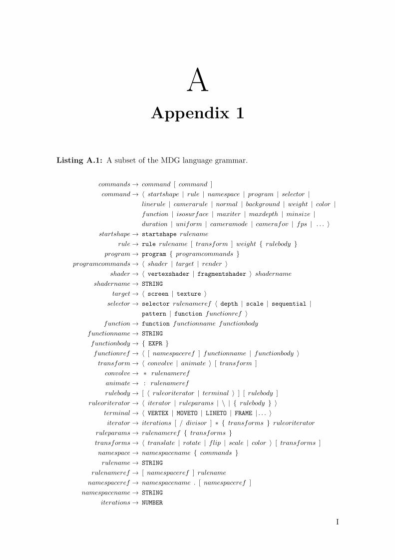
Listing A.1: A subset of the MDG language grammar.
commands→ command [ command ]command→ 〈 startshape | rule | namespace | program | selector |
linerule | camerarule | normal | background | weight | color |function | isosurface | maxiter | maxdepth | minsize |duration | uniform | cameramode | camerafov | fps | . . . 〉
startshape→ startshape rulename
rule→ rule rulename [ transform ] weight { rulebody }program→ program { programcommands }
programcommands→ 〈 shader | target | render 〉shader → 〈 vertexshader | fragmentshader 〉 shadername
shadername→ STRING
target→ 〈 screen | texture 〉selector → selector rulenameref 〈 depth | scale | sequential |
pattern | function functionref 〉function→ function functionname functionbody
functionname→ STRING
functionbody → { EXPR }functionref → 〈 [ namespaceref ] functionname | functionbody 〉transform→ 〈 convolve | animate 〉 [ transform ]convolve→ ∗ rulenameref
animate→ : rulenameref
rulebody → [ 〈 ruleoriterator | terminal 〉 ] [ rulebody ]ruleoriterator → 〈 iterator | ruleparams | \ | { rulebody } 〉
terminal→ 〈 VERTEX | MOVETO | LINETO | FRAME | . . . 〉iterator → iterations [ / divisor ] ∗ { transforms } ruleoriterator
ruleparams→ rulenameref { transforms }transforms→ 〈 translate | rotate | flip | scale | color 〉 [ transforms ]namespace→ namespacename { commands }rulename→ STRING
rulenameref → [ namespaceref ] rulenamenamespaceref → namespacename . [ namespaceref ]
namespacename→ STRING
iterations→ NUMBER
I
A. Appendix 1
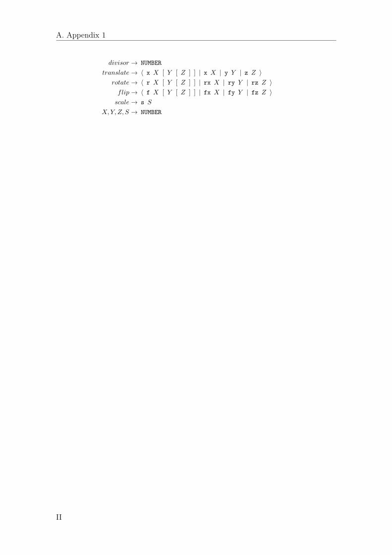
divisor → NUMBER
translate→ 〈 x X [ Y [ Z ] ] | x X | y Y | z Z 〉rotate→ 〈 r X [ Y [ Z ] ] | rx X | ry Y | rz Z 〉flip→ 〈 f X [ Y [ Z ] ] | fx X | fy Y | fz Z 〉scale→ s S
X, Y, Z, S → NUMBER
II
BAppendix 2
Table B.1: MDG directives
Directive Meaning
startshape rulename shapename is the default rule to be rendered when the program isexecuted
rule rulename [: ta [: tb [: tc... ]]] { ... } prototype code for a rule with associated transforms ta, tb, tc, ...
program { ‹commands› } prototype code for a programlinerule rulename default rule to use for MOVETO and LINETO operationscamerarule rulename transformation rule used for adjusting camera position and directionnamespace ns { ... } defines a namespace section; rule names will be prepended nsduration dur the duration in seconds of the animationisosurface name {‹commands› } declaration of an isosurface
function name { ‹expr› } declaration of a function (mathematical expression with variables x, y, z)selector rulenameselectorname
defines a selector for the rule (valid options for selectorname is ’random’,’scale’ and ’sequential’.)
normal x y z the untransformed normal used by the VERTEX operationfps num num is the default fps (frames per second)
color a b c d a, b, c, d are the strings that represent the four components of the colorattribute (R, G, B, A by default)
weight a b c d a, b, c, d are the strings that represent the four components of theweight attribute (u, v, w, q by default)
randseed num integer that will be used as a seed value for the random numbergenerator
uniform uniformname x [y [z[w]]] sets a uniform in the shader program(s) to the values given by (x y z w)
uniform uniformnamerulename prop
sets a uniform in the shader program(s) to the value given by propertyprop of the current frame of a rule (prop can be ’pos’, ’dir’, ’conj’,’color’, ’weight’ and ’normal’)
angle anglemode changes how angles are interpreted (anglemode may be one of ’degrees’,’arcdegrees’, ’radians’, ’orbits’ and ’frequency’)
minsize value a minimum threshold value of the scale to indicate when recursionshould stop
stacksize value a maximum threshold value for the stack, to indicate when recursionshould stop (advanced)
buffersize value how many values to buffer in each asynchronous computation (advanced)invalidateskipframes value how many frames to skip before invalidating the current scene bufferscamerafov value field-of-view angle of camera in degrees (default 40°)cameranearplane value camera near plane (default 0.1)camerafarplane value camera far plane (default 1000)background r g b a change the background color
III
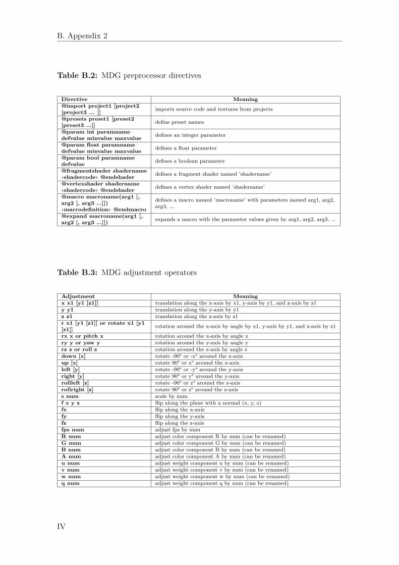
B. Appendix 2
Table B.2: MDG preprocessor directives
Directive Meaning@import project1 [project2[project3 ... ]] imports source code and textures from projects
@presets preset1 [preset2[preset3 ...]] define preset names
@param int paramnamedefvalue minvalue maxvalue defines an integer parameter
@param float paramnamedefvalue minvalue maxvalue defines a float parameter
@param bool paramnamedefvalue defines a boolean parameter
@fragmentshader shadername‹shadercode› @endshader defines a fragment shader named ’shadername’
@vertexshader shadername‹shadercode› @endshader defines a vertex shader named ’shadername’
@macro macroname(arg1 [,arg2 [, arg3 ...]])‹macrodefinition› @endmacro
defines a macro named ’macroname’ with parameters named arg1, arg2,arg3, ...
@expand macroname(arg1 [,arg2 [, arg3 ...]]) expands a macro with the parameter values given by arg1, arg2, arg3, ...
Table B.3: MDG adjustment operators
Adjustment Meaningx x1 [y1 [z1]] translation along the x-axis by x1, y-axis by y1, and z-axis by z1y y1 translation along the y-axis by y1z z1 translation along the z-axis by z1r x1 [y1 [z1]] or rotate x1 [y1[z1]] rotation around the x-axis by angle by x1, y-axis by y1, and z-axis by z1
rx x or pitch x rotation around the x-axis by angle xry y or yaw y rotation around the y-axis by angle yrz z or roll z rotation around the z-axis by angle zdown [x] rotate -90° or -x° around the x-axisup [x] rotate 90° or x° around the x-axisleft [y] rotate -90° or -y° around the y-axisright [y] rotate 90° or y° around the y-axisrollleft [z] rotate -90° or z° around the z-axisrollright [z] rotate 90° or z° around the z-axiss num scale by numf x y z flip along the plane with a normal (x, y, z)fx flip along the x-axisfy flip along the y-axisfz flip along the z-axisfps num adjust fps by numR num adjust color component R by num (can be renamed)G num adjust color component G by num (can be renamed)B num adjust color component B by num (can be renamed)A num adjust color component A by num (can be renamed)u num adjust weight component u by num (can be renamed)v num adjust weight component v by num (can be renamed)w num adjust weight component w by num (can be renamed)q num adjust weight component q by num (can be renamed)
IV
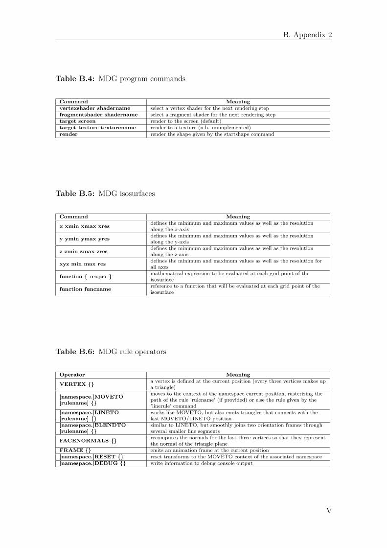
B. Appendix 2
Table B.4: MDG program commands
Command Meaningvertexshader shadername select a vertex shader for the next rendering stepfragmentshader shadername select a fragment shader for the next rendering steptarget screen render to the screen (default)target texture texturename render to a texture (n.b. unimplemented)render render the shape given by the startshape command
Table B.5: MDG isosurfaces
Command Meaning
x xmin xmax xres defines the minimum and maximum values as well as the resolutionalong the x-axis
y ymin ymax yres defines the minimum and maximum values as well as the resolutionalong the y-axis
z zmin zmax zres defines the minimum and maximum values as well as the resolutionalong the z-axis
xyz min max res defines the minimum and maximum values as well as the resolution forall axes
function { ‹expr› } mathematical expression to be evaluated at each grid point of theisosurface
function funcname reference to a function that will be evaluated at each grid point of theisosurface
Table B.6: MDG rule operators
Operator Meaning
VERTEX {} a vertex is defined at the current position (every three vertices makes upa triangle)
[namespace.]MOVETO[rulename] {}
moves to the context of the namespace current position, rasterizing thepath of the rule ’rulename’ (if provided) or else the rule given by the’linerule’ command
[namespace.]LINETO[rulename] {}
works like MOVETO, but also emits triangles that connects with thelast MOVETO/LINETO position
[namespace.]BLENDTO[rulename] {}
similar to LINETO, but smoothly joins two orientation frames throughseveral smaller line segments
FACENORMALS {} recomputes the normals for the last three vertices so that they representthe normal of the triangle plane
FRAME {} emits an animation frame at the current position[namespace.]RESET {} reset transforms to the MOVETO context of the associated namespace[namespace.]DEBUG {} write information to debug console output
V

B. Appendix 2
VI

CAppendix 3
Listing C.1: Basic vertex and fragment shaders used for models.
@fragmentshader FS
precision mediump float;
varying vec3 normal;
varying vec4 vertPos;
varying vec3 cameraPos;
varying vec4 weight;
varying vec4 color;
uniform vec3 lightPos;
uniform vec3 specColor;
uniform float phongPower;
void main() {
vec3 normal = normalize(normal);
if (!gl_FrontFacing) {
normal = -normal;
}
vec3 lightDir = normalize(vertPos.xyz - lightPos);
float lambertian = max(dot(lightDir,normal), 0.0);
float specular = 0.0;
if(lambertian > 0.0) {
vec3 reflectDir = normalize(reflect(lightDir, normal));
vec3 viewDir = normalize(cameraPos - vertPos.xyz);
float specAngle = max(dot(reflectDir, viewDir), 0.0);
specular = pow(specAngle, phongPower);
}
gl_FragColor = vec4( lambertian*color.rgb +
specular*specColor, 1.0 + color.a);
}
@endshader
@vertexshader VS
attribute vec4 aVertexPosition;
attribute vec3 aVertexNormal;
attribute vec4 aVertexWeight;
attribute vec4 aVertexColor;
attribute float aVertexBone;
uniform mat3 uNMatrix;
uniform mat4 uPMatrix;
uniform mat4 uBoneMatrix[60];
uniform vec3 uCameraPos;
varying vec4 vertPos;
varying vec3 cameraPos;
varying vec3 normal;
varying vec4 weight;
varying vec4 color;
mat3 getNormalMat(mat4 mat) {
return mat3(mat[0][0], mat[1][0], mat[2][0], mat[0][1], mat
[1][1], mat[2][1], mat[0][2], mat[1][2], mat[2][2]);
}
void main(void) {
mat4 uMVMatrix = uBoneMatrix[int(aVertexBone)];
vertPos = uMVMatrix * aVertexPosition;
cameraPos = uCameraPos;
gl_Position = uPMatrix * vertPos;
normal = aVertexNormal * getNormalMat(uMVMatrix);
weight = aVertexWeight;
color = aVertexColor;
}
@endshader
program {
vertexshader VS
fragmentshader FS
target screen
render
}
Listing C.2: Model describing a class of knots with a number of revolutions abouteach axis.
startshape START
linerule LINERULE
angle orbits
rule LINERULE {
12/12*{rz 1} VERTEX{x 1}
}
rule START{
NEWLINE{}
ring{s 2 R 1 G 0.3}
}
rule ring * zpath : ypath : xpath {
ALINETO{z 0.2 s 0.3}
}
rule zpath {
4000/4000*[rz 9] FRAME{}
}
rule ypath {
4000/4000*[ry 81] FRAME{}
}
rule xpath {
4000/4000*[rx 16] FRAME{}
}
VII
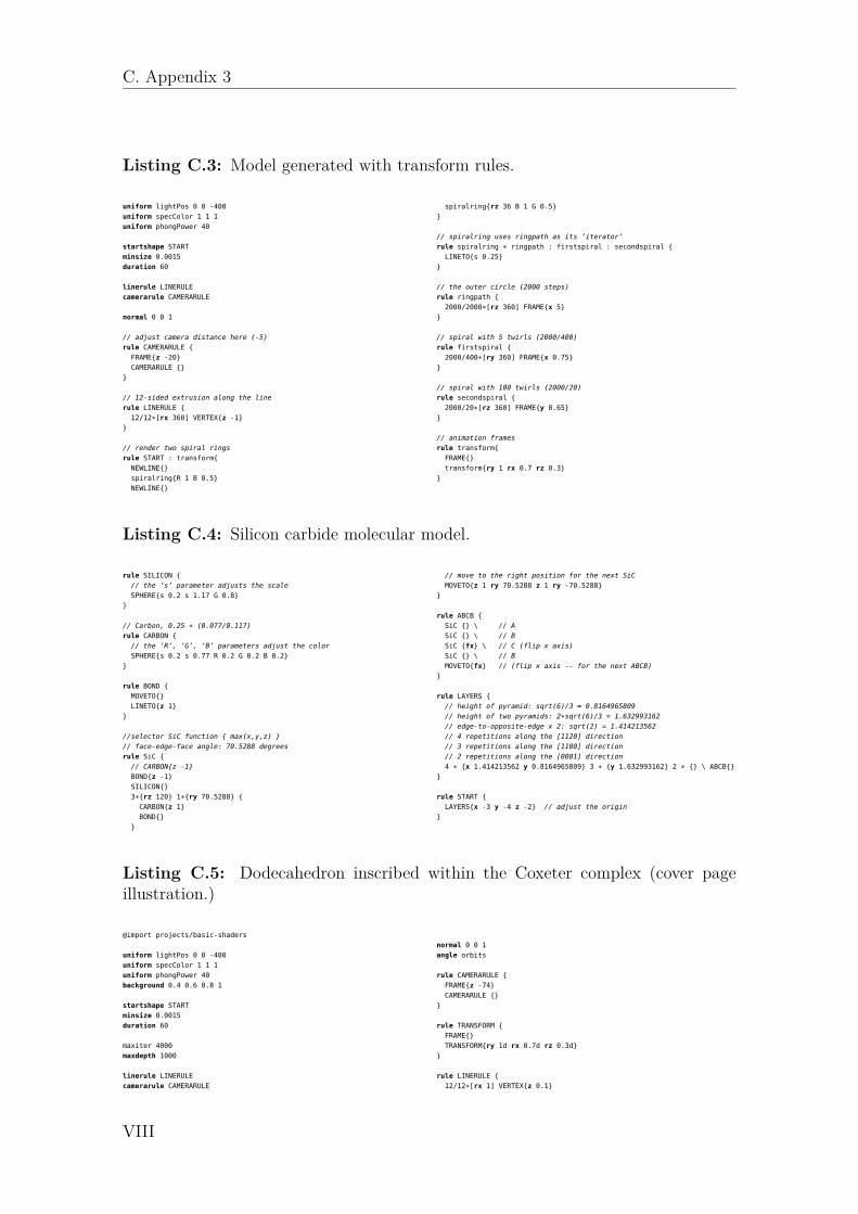
C. Appendix 3
Listing C.3: Model generated with transform rules.
uniform lightPos 0 0 -400
uniform specColor 1 1 1
uniform phongPower 40
startshape START
minsize 0.0015
duration 60
linerule LINERULE
camerarule CAMERARULE
normal 0 0 1
// adjust camera distance here (-5)
rule CAMERARULE {
FRAME{z -20}
CAMERARULE {}
}
// 12-sided extrusion along the line
rule LINERULE {
12/12*[rx 360] VERTEX{z -1}
}
// render two spiral rings
rule START : transform{
NEWLINE{}
spiralring{R 1 B 0.5}
NEWLINE{}
spiralring{rz 36 B 1 G 0.5}
}
// spiralring uses ringpath as its ’iterator’
rule spiralring * ringpath : firstspiral : secondspiral {
LINETO{s 0.25}
}
// the outer circle (2000 steps)
rule ringpath {
2000/2000*[rz 360] FRAME{x 5}
}
// spiral with 5 twirls (2000/400)
rule firstspiral {
2000/400*[ry 360] FRAME{x 0.75}
}
// spiral with 100 twirls (2000/20)
rule secondspiral {
2000/20*[rz 360] FRAME{y 0.65}
}
// animation frames
rule transform{
FRAME{}
transform{ry 1 rx 0.7 rz 0.3}
}
Listing C.4: Silicon carbide molecular model.
rule SILICON {
// the ’s’ parameter adjusts the scale
SPHERE{s 0.2 s 1.17 G 0.8}
}
// Carbon, 0.25 * (0.077/0.117)
rule CARBON {
// the ’R’, ’G’, ’B’ parameters adjust the color
SPHERE{s 0.2 s 0.77 R 0.2 G 0.2 B 0.2}
}
rule BOND {
MOVETO{}
LINETO{z 1}
}
//selector SiC function { max(x,y,z) }
// face-edge-face angle: 70.5288 degrees
rule SiC {
// CARBON{z -1}
BOND{z -1}
SILICON{}
3*{rz 120} 1*{ry 70.5288} {
CARBON{z 1}
BOND{}
}
// move to the right position for the next SiC
MOVETO{z 1 ry 70.5288 z 1 ry -70.5288}
}
rule ABCB {
SiC {} \ // A
SiC {} \ // B
SiC {fx} \ // C (flip x axis)
SiC {} \ // B
MOVETO{fx} // (flip x axis -- for the next ABCB)
}
rule LAYERS {
// height of pyramid: sqrt(6)/3 = 0.8164965809
// height of two pyramids: 2*sqrt(6)/3 = 1.632993162
// edge-to-opposite-edge x 2: sqrt(2) = 1.414213562
// 4 repetitions along the [1120] direction
// 3 repetitions along the [1100] direction
// 2 repetitions along the [0001] direction
4 * {x 1.414213562 y 0.8164965809} 3 * {y 1.632993162} 2 * {} \ ABCB{}
}
rule START {
LAYERS{x -3 y -4 z -2} // adjust the origin
}
Listing C.5: Dodecahedron inscribed within the Coxeter complex (cover pageillustration.)
@import projects/basic-shaders
uniform lightPos 0 0 -400
uniform specColor 1 1 1
uniform phongPower 40
background 0.4 0.6 0.8 1
startshape START
minsize 0.0015
duration 60
maxiter 4000
maxdepth 1000
linerule LINERULE
camerarule CAMERARULE
normal 0 0 1
angle orbits
rule CAMERARULE {
FRAME{z -74}
CAMERARULE {}
}
rule TRANSFORM {
FRAME{}
TRANSFORM{ry 1d rx 0.7d rz 0.3d}
}
rule LINERULE {
12/12*[rx 1] VERTEX{z 0.1}
VIII
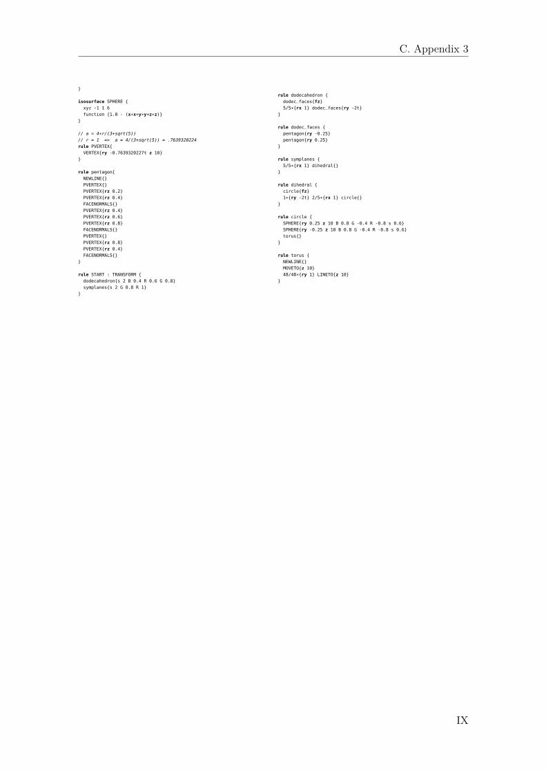
C. Appendix 3
}
isosurface SPHERE {
xyz -1 1 6
function {1.0 - (x*x+y*y+z*z)}
}
// a = 4*r/(3+sqrt(5))
// r = 1 => a = 4/(3+sqrt(5)) = .7639320224
rule PVERTEX{
VERTEX{ry -0.7639320227t z 10}
}
rule pentagon{
NEWLINE{}
PVERTEX{}
PVERTEX{rz 0.2}
PVERTEX{rz 0.4}
FACENORMALS{}
PVERTEX{rz 0.4}
PVERTEX{rz 0.6}
PVERTEX{rz 0.8}
FACENORMALS{}
PVERTEX{}
PVERTEX{rz 0.8}
PVERTEX{rz 0.4}
FACENORMALS{}
}
rule START : TRANSFORM {
dodecahedron{s 2 B 0.4 R 0.6 G 0.8}
symplanes{s 2 G 0.8 R 1}
}
rule dodecahedron {
dodec_faces{fz}
5/5*{rx 1} dodec_faces{ry -2t}
}
rule dodec_faces {
pentagon{ry -0.25}
pentagon{ry 0.25}
}
rule symplanes {
5/5*{rx 1} dihedral{}
}
rule dihedral {
circle{fz}
1*{ry -2t} 2/5*{rx 1} circle{}
}
rule circle {
SPHERE{ry 0.25 z 10 B 0.8 G -0.4 R -0.8 s 0.6}
SPHERE{ry -0.25 z 10 B 0.8 G -0.4 R -0.8 s 0.6}
torus{}
}
rule torus {
NEWLINE{}
MOVETO{z 10}
48/48*{ry 1} LINETO{z 10}
}
IX