proceedings of 28th european space thermal analysis … · summer solstice winter solstice 10 apr....
TRANSCRIPT
79
Appendix G
An overview of CHEOPS Instrument thermal design and analysis
Romain Peyrou-Lauga(ESA, The Netherlands)
Giordano Bruno(University of Bern, Switzerland)
28th European Space Thermal Analysis Workshop 14–15 October 2014

80 An overview of CHEOPS Instrument thermal design and analysis
Abstract
CHEOPS (CHaracterizing ExoPlanet Satellite) is the first ESA S-class mission and is dedicated to searchfor planet transits by means of ultrahigh precision photometry on bright stars already known to hostplanets. The University of Bern is in charge of the CHEOPS instrument, which is a single aperture, highaccuracy photometer operating between 0.4 and 1.1 micron. The focal plane detector consists of a singleCCD operated at -40 ◦C and requires a thermal stability better than 10 mK. The presentation will providean overview of the thermal design and of the thermal analysis of the instrument.
28th European Space Thermal Analysis Workshop 14–15 October 2014

An overview of CHEOPS Instrument thermal design and thermal analysis
Giordano Bruno (University of Bern)Romain Peyrou‐Lauga (ESA) Thermal analysis workshop – ESTEC – 14‐15 Oct. 2014
Thermal analysis workshop – ESTEC – 14‐15 Oct. 2014
• CHEOPS is the first ESA’s Science Programme of class S (Small mission).
CHEOPS MISSION
• The purpose of the mission is tocharacterise already known exoplanets: it will measure the bulk density of«super‐Earth»‐ and «Neptune»‐mass planets, for future in‐depthcharacterisation studies of exoplanets in these mass ranges.
• A sun synchronous LEO orbit has beenchosen with LTAN 6:00 am and altitudefrom 620 to 800 km.
• The Satellite Attitudes/pointings have been defined on the basis of the allowed observation field, which in turn, must respect the Earth stray light exclusion angles.
An overview of CHEOPS Instrument thermal design and analysis 81
28th European Space Thermal Analysis Workshop 14–15 October 2014
Thermal analysis workshop – ESTEC – 14‐15 Oct. 2014
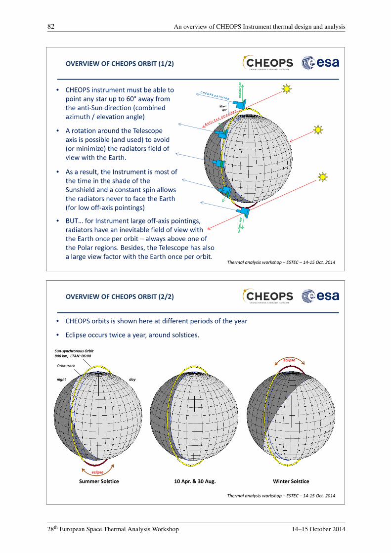
OVERVIEW OF CHEOPS ORBIT (1/2)
• CHEOPS instrument must be able topoint any star up to 60° away fromthe anti‐Sun direction (combinedazimuth / elevation angle)
• As a result, the Instrument is most ofthe time in the shade of theSunshield and a constant spin allowsthe radiators never to face the Earth (for low off‐axis pointings)
• A rotation around the Telescopeaxis is possible (and used) to avoid(or minimize) the radiators field ofview with the Earth.
• BUT… for Instrument large off‐axis pointings, radiators have an inevitable field of view withthe Earth once per orbit – always above one ofthe Polar regions. Besides, the Telescope has also a large view factor with the Earth once per orbit.
Radiator FoV
Thermal analysis workshop – ESTEC – 14‐15 Oct. 2014
OVERVIEW OF CHEOPS ORBIT (2/2)
night day
Sun‐synchronous Orbit 800 km, LTAN: 06:00
eclipse
eclipseOrbit track
Summer Solstice Winter Solstice10 Apr. & 30 Aug.
• CHEOPS orbits is shown here at different periods of the year
• Eclipse occurs twice a year, around solstices.
82 An overview of CHEOPS Instrument thermal design and analysis
28th European Space Thermal Analysis Workshop 14–15 October 2014

Solar Arrays panels
SunshieldCHEOPS Instrument
Star Tracker
CHEOPS PlatformInstrument
Cover (open)
InstrumentRadiators
Sunshield
Platformradiators
• Enveloping dimensions: 1.5 m × 1.4 m × 1.5 m
CHEOPS SPACECRAFT
Thermal analysis workshop – ESTEC – 14‐15 Oct. 2014
• Spacecraft overall mass < 250 kg
• Instrument radiators dimension is limited by the max allowed volume for the Spacecraft accomodation in the launcher
• 60 W of continuous power provided to the Instrument by the Spacecraft
Thermal analysis workshop – ESTEC – 14‐15 Oct. 2014
CHEOPS INSTRUMENT THERMAL REQUIREMENTS
FPA Radiator: ‐70°C to +40°C
FEE Radiator: ‐70°C to +40°C
Front End Electronic (FEE): set‐point +4°CStability < 50 mK
FPA CCD: set‐point ‐40°CStability < 10 mK
Telescope tube (TEL): Set‐point: ‐10°CStability < 10 K
Telescope baffle (BCA): ‐80°C to +60°C
Thermal insulation
Thermal insulation
An overview of CHEOPS Instrument thermal design and analysis 83
28th European Space Thermal Analysis Workshop 14–15 October 2014

Thermal analysis workshop – ESTEC – 14‐15 Oct. 2014
Radiators: White paint = 0.8, EOL = 0.25
External black MLI: = 0.84, = 0.93
Thermal analysis workshop – ESTEC – 14‐15 Oct. 2014
CHEOPS INSTRUMENT THERMAL ARCHITECTURE: COATINGS THERMO‐OPTICAL PROPERTIES
TEL + BCA vanes: black paint: = 0.9, = 0.95
Internal VDA MLI: = 0.05
Mirror front side: silver coating: = 0.03, = 0.12Mirror rear side: bare zerodur: = 0.8, = 0.5
Thermal insulation
Thermal analysis workshop – ESTEC – 14‐15 Oct. 2014
FPA CCD operational heater line (PID controller)
CCD cover: black inside, gold outside
Silver thermal strap
Beryllium capacitor gold coated
FPA radiator back side: Alodine 1200 + VDA MLI
FPA cold‐block: gold coated
CCD survival heater line + thermistors (ON/OFF)
CHEOPS INSTRUMENT THERMAL ARCHITECTURE: FPA THERMAL DESIGN
The FPA thermal control includes:
• High conductance thermal pathbetween the detector and theradiator (high conductancematerials)
• High thermal inertia capacitorto help temperaturestabilization
• Mechanical decouplingbetween the detector and theradiator
• Thermal insulation from theradiative and conductiveenvironment
• PID law controlled heating line
FPA radiator front side: white painted = 0.8, EOL = 0.25
84 An overview of CHEOPS Instrument thermal design and analysis
28th European Space Thermal Analysis Workshop 14–15 October 2014

Thermal analysis workshop – ESTEC – 14‐15 Oct. 2014
FPA radiator front side: white painted = 0.8, EOL = 0.25 FPA radiator back side:
Alodine 1200 + VDA MLI
Beryllium capacitor gold coated
Silver thermal strap
FEE cover gold coated
FEE structure gold coated
FEE survival heater line + thermistors (ON/OFF)
FEE operational heater line (PID controller)
CHEOPS INSTRUMENT THERMAL ARCHITECTURE: FEE THERMAL DESIGN
FEE cover gold coated
The FEE thermal controlpresents similar featuresthan the FPA (as seenpreviously):
• High conductance
• High thermal inertia
• Mechanical decoupling
• Thermal insulation
• PID law
Thermal analysis workshop – ESTEC – 14‐15 Oct. 2014
CHEOPS INSTRUMENT THERMAL ARCHITECTURE: TELESCOPE THERMAL CONTROL
Thermal analysis workshop – ESTEC – 14‐15 Oct. 2014
Structural tube
VDA MLI
Operational heaters (black kapton)
TEL tube
Survival heaters(black kapton)
ON/OFF control Type
External MLI
The Telescope thermal control includes:
• 2 sets of MLI (one for each tube)
• Several local heating lines to counter gradients
An overview of CHEOPS Instrument thermal design and analysis 85
28th European Space Thermal Analysis Workshop 14–15 October 2014

Thermal analysis workshop – ESTEC – 14‐15 Oct. 2014
UP‐TO‐DATE CHEOPS GEOMETRICAL MODEL
FPA Radiator
FEE Radiator
FPA RadiatorFEE Radiator
Heat shield
Platform
Optical bench
Thermal analysis workshop – ESTEC – 14‐15 Oct. 2014
• An extensive survey has beenperformed by ESA at SRR, of all thepossible attitudes, with Azimuth andElevation steps of 5°/10° inside therequired range (blue line in thepicture)
THERMAL ANALYSIS AT SRR
• Azimut has been defined wrt the ecliptic plane, while the Elevation wrt toortogonal plane to the ecliptic plane, containing the Sun and the Satellite
86 An overview of CHEOPS Instrument thermal design and analysis
28th European Space Thermal Analysis Workshop 14–15 October 2014

Thermal analysis workshop – ESTEC – 14‐15 Oct. 2014
• The stability/gradients maps of theTEL tube, Mirrors, FPA CCD and FEEhave been worked out, allowing toidentify the attitude worst condition.
THERMAL ANALYSIS AT SRR
• Two worst cases have beenidentified:
• cold case: 10th of April in anti‐sun pointing
• hot case: winter solstice, pointing at the boundary of the observed field
Thermal analysis workshop – ESTEC – 14‐15 Oct. 2014
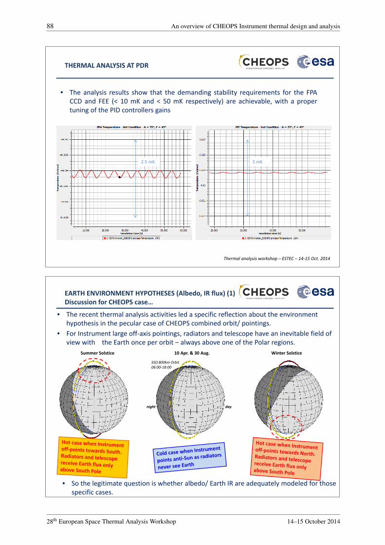
THERMAL ANALYSIS AT PDR
• The insights of the SRR have been developed by Unibe in Systema / Thermica• The margin policy has been consolidated:
• an uncertainty of ‐10°C on the FPA and FEE set‐points in hot condition, for theFPA and FEE radiators design
• An uncertainty of +10°C on the FPA and FEE set‐points in cold condition, forthe TC power sizing
CHEOPS ABOVE SOUTH POLE: A=0°, E= 60°, Direct solar flux(Systema/Thermica)
An overview of CHEOPS Instrument thermal design and analysis 87
28th European Space Thermal Analysis Workshop 14–15 October 2014
Thermal analysis workshop – ESTEC – 14‐15 Oct. 2014
THERMAL ANALYSIS AT PDR
• The analysis results show that the demanding stability requirements for the FPACCD and FEE (< 10 mK and < 50 mK respectively) are achievable, with a propertuning of the PID controllers gains
2.5 mK 5 mK
night day
SSO 800km Orbit06:00‐18:00
Summer Solstice Winter Solstice10 Apr. & 30 Aug.
EARTH ENVIRONMENT HYPOTHESES (Albedo, IR flux) (1)Discussion for CHEOPS case…
• The recent thermal analysis activities led a specific reflection about the environmenthypothesis in the pecular case of CHEOPS combined orbit/ pointings.
• For Instrument large off‐axis pointings, radiators and telescope have an inevitable field ofview with the Earth once per orbit – always above one of the Polar regions.
• So the legitimate question is whether albedo/ Earth IR are adequately modeled for thosespecific cases.
88 An overview of CHEOPS Instrument thermal design and analysis
28th European Space Thermal Analysis Workshop 14–15 October 2014

Thermal analysis workshop – ESTEC – 14‐15 Oct. 2014
Max albedo: 0.35 to 0.4
Min Earth IR temp: 240 K to 244 K (201 W/m2 to
Max Earth IR temp: 260 K to 264 K
For the SRR and PDR, usual values of albedo and IR flux were used. Min albedo + min IR flux were cumulated with min Sun flux (winter), which is conservative. As the radiators can receive Earth flux only above the Polar regions, we legitimately wonder if our hypothesis were not too conservative, leading to oversize the FPA and FEE radiators
Gilmore Handbook proposes a set of albedo / IR flux hypotheses depending on the latitude and the season:
night day
EARTH ENVIRONMENT HYPOTHESES (Albedo, IR flux) (2)Common hypotheses…
Yearly average albedo (Guilmore Hdbk)
Min albedo: 0.2 to 0.25
North
South
Yearly average Earth IR temp. (Gilmore Hdbk)
North
South
EARTH ENVIRONMENT HYPOTHESES (Albedo, IR flux) (3)Using measured values of albedo/IR flux
• The idea is then to use real data of albedo / IR flux to get a realistic environment for thethermal simulation. NASA’s CERES experiment provide daily geolocalised data for bothalbedo and IR flux (http://ceres.larc.nasa.gov/)
• Alex Green (PhD UCL/ESA) has computed 5 years of CERES data (2007‐2011) to obtainaveraged albedo /IR flux depending on the latitude, the season but also the orbit.
Albedo
Average yearly IR Earth temp. as viewed from SSO 800km LTAN 6h appears to 250 ±4K.
Statistic orbital averaged value of Albedo for SSO 800km LTAN:6h (CERES data 2007‐2011)
Statistic orbital averaged value of Earth IR temperature for SSO 800km LTAN:6h (CERES
data 2007‐2011)
Average yearly albedo as viewed from SSO 800km LTAN 6h appears to 0.38 ± 0.07.
An overview of CHEOPS Instrument thermal design and analysis 89
28th European Space Thermal Analysis Workshop 14–15 October 2014

Thermal analysis workshop – ESTEC – 14‐15 Oct. 2014
Measured albedo / IR flux (CERES 2007‐2012):EARTH ENVIRONMENT HYPOTHESES (Albedo, IR flux) (4)
Yearly average albedo (CERES data) (shown in Winter solstice)
Yearly average Earth IR temp. (CERES data)
South Pole
South Pole
South Pole
North Pole
North Pole
South Pole
• Another possibility of using CERES data is to take into account local value(depending on latitude):
Yearly average Earth IR temp. (Gilmore data)
Yearly average albedotemp. (Gilmore data)
Earth IR temp. (PDR hyp.)
Earth IR temp. (PDR hyp.)
THANK YOU !Any questions…?
90 An overview of CHEOPS Instrument thermal design and analysis
28th European Space Thermal Analysis Workshop 14–15 October 2014