proceedings of the 14th international middle east … · the linear and rotary induction motors...
TRANSCRIPT

Model Predictive Control of A Speed Sensorless Linear
Induction Motor Drive
Ahmed Abd Eltawwab Hassan,and Yehia Sayed
Mohamed Takashi Hiyama, and Tarek Hassan Mohamed
Faculty of Engineering Minia University Faculty of Electrical Engineering & Computer Science,
Kumamoto University
Minia, Egypt.line Kumamoto, Japan. e-mail address ([email protected]) e-mail address ([email protected])
Abstract - In this paper, the model predictive control (MPC)
technique has been used to control the speed of the linear
induction motor (LIM) drive. The mathematical model of the
LIM has been described in the stationary frame. The longitudinal
end effects of the linear induction motor are taken into account
as external load.The concept of field orientation is used to
decouple the mover speed from the secondary flux. The MPC
technique has been designed such that the effect of the
uncertainty due to motor parameters variation and load
disturbance could be reduced. A simplified LIM model is
introduced in the MPC structure so as to minimize the
computational load. To decrease the associated maintenance cost,
and increase reliability, the most common model reference
adaptive system (MRAS) structure is used to estimate the motor
speed. An adaptive full-order observer based on LIM equation is
used to estimate the primary current and secondary flux.
Lyapunov’s stability criterion is employed to estimate the motor
speed. The same algorithm deduced from Lyapunov’s stability
criterion is given to estimate the stator resistance, which results in the speed estimation error. Digital simulations are provided to validate the effectiveness of
the proposed scheme. The results show that the proposed system
possesses the advantages of good transient performance and
robustness in face of uncertainties. A performance comparison
between the proposed MPC controller and both of sliding mode
and PI control schemes is carried out confirming the superiority
of the proposed MPC technique.
The proposed system has the advantages of increased reliability,
and low cost due to the elimination of the mechanical speed
sensor .
Keywords: Linear induction motor – Field orientation – Electrical elevator – PI controller - model predictive control .
.
1. INTRODUCTION
Linear induction motor has been widely used in a variety
of applications like as transportation, conveyor systems,
actuators, material handling, sliding door closers, curtain
pullers, robot base movers, and so on. It has several advantages such as high starting thrust, simple mechanical
construction, silence, no backlash, and less friction [1-4]. Both
the linear and rotary induction motors have similar driving
principles. However, the control characteristics of the LIM are
more complicated. This is attributed to the time varying motor
parameters as a result of change in operating conditions such
as mover speed, temperature, and rail configuration. Moreover,
there are uncertainties existed in practical applications of the
LIM [5-7] which usually composed of unpredictable plant
parameter variations, external load disturbance, and un-modeled and nonlinear dynamics. Therefore, the LIM drive
system must provide high tracking performance, and high
dynamic stiffness to overcome the above difficulties.
Because of their simplicity and effectiveness, PI controllers
are considered as the most widely used controllers which have
been employed in the electrical machine control systems [8-9].
However, The use of PI controllers for speed control of
induction machine drives is characterized by an overshoot
during tracking mode and exhibits poor load disturbance
rejection.
The fast improvements in power electronic devices and
microelectronics has made possible the application of the field oriented control (FOC) technique on the induction motor
drives [9-10]. It has been applied successfully to the LIM by
aligning the d-axis of the primary current with the secondary
flux linkage. However, the main drawbacks of FOC are the
sensitivity of the system performance to the parameters
variation and inadequate rejection of external disturbances and
load changes.
The direct torque control (DTC) technique [11] was developed
to overcome the drawbacks of the FOC method. The DTC
technique has the merits of fast response and less parameter
dependency. On contrast, the flux and torque waveforms contain large ripples.
Sliding mode control (SMC) is one of the effective means to
control the induction motor drives [12-13]. It has many good
features such as fast dynamic response, simplicity of design
and implementation, and robustness to parameter variations or
load disturbance. However, undesirable chattering appears in
the control effort which excites unmodeled high frequency
plant dynamics and causes unexpected instability.
In the past few years, there has been considerable interest in
the applications of advanced and intelligent control methods to
deal with the nonlinearities and uncertainties of the LIM drive
system. Linear quadratic Gaussian method, neural, fuzzy and
318
Proceedings of the 14th International Middle East Power Systems Conference (MEPCON’10), Cairo University, Egypt, December 19-21, 2010, Paper ID 173.
genetic techniques have been employed for this purpose [14-
17]. In spite of the success of the previous methods to control
the speed or position of the linear motor, new control
techniques are needed to face the large uncertainties existed.
On the other hand, the MPC appears to be an efficient strategy to control many applications in industry [18-19]. It has many
advantages such as very fast response, and robustness against
load disturbance and parameters uncertainty. Moreover, the
MPC controller can provide the optimal solution while
respecting the given constraints.
From the viewpoints of reliability, robustness, and cost,
several approaches have been proposed that addresses the
elimination of the mechanical sensors from induction motor
control schemes. Using current and voltage measuring
devices, the speed of the induction motor can be determined without the need to speed sensors. Several schemes of speed
estimators have been proposed [23-25], among them, the
MRAS approach has relative simplicity and low
computational effort and gives good performance [24].
Several MRAS structures are possible.
In this paper, the speed control of the field oriented LIM drive
has been developed based on MPC technique, The field
orientation principle is used to decouple the mover speed from
the secondary flux amplitude. The MRAS technique is
employed to estimate the the mover speed. The MPC
technique law produces its optimal output derived from a quadratic cost function minimization based on simplified LIM
model. The end-effect of LIM is modeled as an external load force
dependent on the mover speed[28-29]. The technique calculates
the optimal control signal while respecting the given
constraints over the mover speed and developed force. The
speed sensorless LIM drive with the proposed MPC controller
has been tested against parameters uncertainty and load
disturbance using computer simulation. The performance of
the MPC has been validated versus the SMC and the
traditional PI controllers. Simulation results proved that the
proposed controller can be applied successfully to control the speed sensorless LIM drive very efficiently.
The paper is organized as follows: Section 2 presents the
dynamic model of the linear induction motor. Indirect field
oriented technique is described in section 3. General
consideration about MPC and its cost function are presented in
section 4. A description of a common MRAS estimator is
found in section 5. The implementation scheme of the
sensorless LIM drive together with the MPC controller is
described in section 6. Simulation results and general remarks
are presented in section 7. Finally, the conclusions are given in
section 8.
2. LIM Dynamic Model
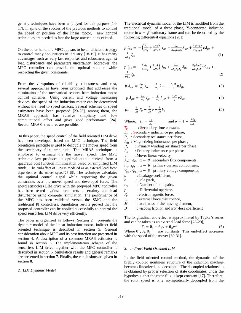
The electrical dynamic model of the LIM is modified from the
traditional model of a three phase, Y-connected induction
motor in stationary frame and can be described by the
following differential equations [20]:
(1)
(2)
(3)
(4)
(5)
Where,
, and
: Secondary time constant,
: Secondary inductance per phase,
: Secondary resistance per phase,
: Magnetizing inductance per phase,
: Primary winding resistance per phase,
: Primary inductance per phase
: Mover linear velocity,
: secondary flux components,
: primary current components,
: primary voltage components,
: Leakage coefficient, h : Pole pitch,
: Number of pole pairs.
: Differential operator.
: electromagnetic force,
: external force disturbance,
: total mass of the moving element,
: viscous friction and iron-loss coefficient
The longitudinal end-effect is approximated by Taylor’s series
and can be taken as an external load force [28-29],
(6)
Where are constants. This end-effect increases
with the speed of the mover [30-31].
3. Indirect Field Oriented LIM
In the field oriented control method, the dynamics of the
highly coupled nonlinear structure of the induction machine
becomes linearized and decoupled. The decoupled relationship
is obtained by proper selection of state coordinates, under the hypothesis that the rotor flux is kept constant [17]. Therefore,
the rotor speed is only asymptotically decoupled from the
319

rotor flux, and is linearly related to the torque current only
after the rotor flux becomes in the steady state case.
The flux model of the LIM can be described in the d-q
synchronous frame as:
(7)
(8)
Where:
: secondary flux components,
: primary current components,
: synchronous linear velocity ,
:supply frequency.
In an ideally decoupled induction motor, the secondary flux
linkage axis is forced to be aligned with the d-axis, and the
field orientation conditions can be applied. It follows that:
, and (9)
Using equation (9), the desired secondary flux linkage in
terms of can be found from equation (7) as
(10)
Moreover, equation (8) can be combined with equations (9)
and (10) to give the feedforward slip velocity signal as
follows:
(11)
The electromagnetic force can be described in the d-q
synchronous frame as [17]:
(12)
Where is the force constant which is equal to:
With the implementation of the field oriented control, equation
(12) can be rewritten using equations (9) and (10) as:
(13)
Where
If the d-axis primary current (flux current component) is kept
constant at the rated value, therefore the electromagnetic
force is directly proportional to the q-axis current; which can
be realized via closed loop control. In this case, if the q-axis
current (load current component) is rapidly changed in
response to the load variation, this will be followed by a rapid
change in the motor developed force and the LIM will exhibit
a high dynamic performance.
4. model predictive control
Due to its simplicity and effectiveness as a control
technique. MPC has proved to efficiently control a wide range of applications in industry such as : chemical process, petrol
industry, electromechanical systems and many other
applications. The MPC scheme is based on an explicit use of a
prediction model of the system response to obtain the control
actions by minimizing an objective function. Optimization
objectives include minimization of the difference between the
predicted and reference response, and the control effort
subjected to prescribed constraints. The effectiveness of MPC
is demonstrated to be equivalent to the optimal control. It
displays its main strength in its computational expediency,
real-time applications, intrinsic compensation for time delays, treatment of constraints, and potential for future extensions of
the methodology. At each control interval, the first input in the
optimal sequence is sent into the plant, and the entire
calculation is repeated at subsequent control intervals. The
purpose of taking new measurements at each time step is to
compensate for unmeasured disturbances and model
inaccuracy, both of which cause the system output to be
different from the one predicted by the model[18-19].
Figure 1 shows a simple structure of the MPC controller. An
internal model is used to predict the future plant outputs based
on the past and current values of the inputs and outputs and on the proposed optimal future control actions. the prediction has
two main components : The free response which being
expected behavior of the output assuming zero future control
actions, and the forced response which being the additional
component of the output response due to the candidate set of
future controls. For a linear systems, the total prediction can
be calculated by summing both of free and forced responses,
reference trajectory signal is the target values the output
should attain. The optimizer is used to calculate the best set of
future control action by minimizing the cost function J, the
optimization is subject to constraints on both manipulated and
controlled variables [21,22]. The general object is to tighten the future output error to zero,
with minimum input effort. The cost function to be minimized
is generally a weighted sum of square predicted errors and
square future control values, e.g. in the Generalized Predictive
Control (GPC) :
(14)
320

Where are the lower and upper prediction horizons
over the output, is the control horizon, are
weighting factors. The control horizon permits to decrease the
number of calculated future control according to the relation:
for .
represents the reference trajectory over the future
horizon .
Constraints over the control signal, the outputs and the control
signal changing can be added to the cost function:
(15)
Solution of equation (14) gives the optimal sequence of
control signal over the horizon while respecting the given
constraints of equation (15).
Model Predictive Control have many advantages, in
particularly it can pilot a big variety of process, being simple
to apply in the case of multivariable system, can compensate the effect of pure delay by the prediction, inducing the
anticipate effect in closed loop, being a simple technique of
control to be applied and also offer optimal solution while
respecting the given constraints. On the other hand, this type
of restructure required the knowledge of model for the system,
and in the present of constraints it becomes a relatively more
complex regulator than the PID for example, and it takes more
time for on-line calculations
Model
Model
Past
Past
outputs
controls
Optimizer
Free responce
Reference
trajectory
Forced
response
Total
response
Future
controls
Cost function
J
Constraints
_+
+ +
Future
errors
Fig. 1 A simple structure of the MPC controller
5 Adaptive speed and primary resistance estimations
Equations (1-4) are used as the reference model and can be
used rewritten in matrix form as:
(16)
Where:
, , ,
,
,
,
,
,
, and
I , J are unit matrix and skew symmetric matrix respectively
where:
The full order adaptive observer for the primary current and
secondary flux can be deduced using equation (16) as
follows :
(17)
Where “^” signifies the estimated value.
Since the primary current can be measured easily, then it is
selected as the error feedback value. Subtracting equation 17
from 16 and assuming = would result :
(18)
Where and G is the observer gain matrix.
The error between the states , and can be used to derive
a speed adaptive control mechanism which adjusts the
estimated speed .
A Lyapunov’s function can be selected as [27]:
(19)
Where, Q , F are both positive symmetric matrices, and
The derivative of with respect to time is as follows:
(20 )
Where and
Using the Lyapunov’s stability theory [26], we can construct a
mechanism to adapt the mechanical speed from the asymptotic
convergence’s condition of the current estimation errors :
(21)
Also, according to the same Lyapunov’s theory, the primary
resistance Rs can be estimated as:
(22)
Where kPv , kIv, kPR, kIR are PI parameters of speed and stator
resistance adaptive estimators respectively, and
is the
integral Laplace operator. The block diagram which illustrates
the use of MRAS to estimate the mover speed and the primary resistance of the LIM is shown in Fig. (2).
321

LIM
B
P[is ,λr]^ ^
∫ C[is ,λr]
^^T
T
f(is-is)^
A+G
v^
^λr
^
-
+
is ^
+
+
e
is us
Fig. 2 Estimation of the mover speed and primary resistance
of the LIM using MRAS technique.
6. System configuration
The block diagram of the indirect field oriented LIM drive
system including the proposed MPC controller is shown in
Fig. 3.
The indirect field oriented LIM drive system consists of
LIM, current controlled voltage source inverter, hysteresis
current controller, field orientation mechanism, and coordinate
translators. On the other hand, the primary currents and
stator votages are obtained using coordinate
translation of measured primary currents and voltages
respectively, and used as input signals of MRAS observer to
give the estimated speed v
which used for closed loop control
and compared with the reference speed. The estimated and
reference speeds are fed to the model predictive controller in
order to obtain the force current command . The flux current
command is set at rated value. The force and flux current
commands are used to obtain the slip command using
equations (11). This latter is added to the actual speed, and the
sum is integrated to obtain the field angle . Therefore the
commanded phase currents are obtained using coordinate
translation of
, and
. The 3-phase primary currents are
measured and fed to hysteresis current controller. The current
controlled pulse width modulation with hysteresis controller regulates the actual primary phase currents to closely follow
the sinusoidal commanded currents.
Using indirect field oriented technique, the transfer function of
the motor can be deduced using equation (5) as:
Transfer function
(23)
For easy implantation, the simplified linearized model of the
LIM described by equation (23) is employed in the structure
of the MPC controller.
RectifierPWM
inverter
Sa Sb Sc
ia ib ic* * *
Hysteresis
Current
controller
Coordinate
translator
Optimizer
Linearizedmodel
_
+
L
Slip
Callculator
iq*
id*
+
np
+Π / h ∫
LIM
v
ve
3-phasecurrents
θe
MPC controller
v*
3-phase C
MRAS
Vαs , Vβs
iαs , iβs
V^
^
Fig. 3 Block diagram of the indirect field oriented Linear
induction motor drive
7. Results and Discussions
Computer simulations have been carried out in order to
validate the effectiveness of the proposed scheme. The Matlab
/ Simulink software package has been used for this purpose. The data of the LIM used for simulation procedure are [17]:
3-phase, Y-connected, 8-pole, 3-kW, 60-Hz, 180-V, 14.2 A.
The motor detailed parameters are listed below in table .1.
The parameters of the MPC controller are set as follows:
Prediction horizon = 60,
control horizon = 40,
Weights on manipulated variables = 0 ,
Weights on manipulated variable rates = 0.1 ,
Weights on the output signals = 100,
Sampling interval = 0.0003 sec.
Constraints are imposed over the developed force, and motor speed as :
Max. developed force = 1000 N.
Min. developed force = 0 N.
Max. mover speed = 1.5 m/sec.
Min. mover speed = -1 m/sec.
The parameters of MRAS observer are:
KIv= 5000000 and KPv= 200.
KIR= 10000 and KPR= 5.
Firstly, the dynamic response of the system is investigated
under the condition of load disturbance effect. Figure (4)
322

shows the simulation results of the proposed scheme in this
case assuming nominal motor parameters. The LIM is
assumed to start at t=0 and accelerated up to 1 m/sec in the
first 0.1 second, then the motor speed is kept constant at this
value during the next 0.8 second, and decelerated till zero
speed is reached during the next 0.1 sec (short acceleration
and deceleration times are suitable for the used small LIM ).
The results from the top to the bottom are: the reference,
estimated and actual speeds, d-q secondary flux components,
3-phase primary currents, developed force, and the external
load force (The load force is assumed to be stepped from 350 N to 700 N at t = 0.5 second. In additional to that force produced by
the end effect (putting .).
It has been noticed that the reference and both of estimated
and actual speeds are aligned and good tracking performance
has been achieved in spite of the load disturbance. Also the
figure indicates that the actual d-axis secondary flux is equal
to the set value (0.0568 wb) while the actual q-axis flux is kept
zero during the simulation period. This means that the field
orientation condition has been realized which leads to high
dynamic performance drive. The figure reports also that the
developed force follows the increase of the load disturbance.
Similarly, the primary phase currents respond quickly to the
speed and load variations.
Fig. (4) Dynamic response of the proposed system with load
disturbance and the end effect: a) estimated and actual speeds, b) d-q
secondary flux components, c) 3-phase primary currents,
d)developed force, and e)load force plus force represents the end effect.
.
Secondly, the robustness of the MPC controller against
parameter uncertainty was validated, in this case, the
secondary resistance was increased by 15% in the LIM model
( ), while it is kept at its nominal
value in both of the controller and the slip calculator, also, the
mover mass amount was increased by 50% ( ) only in the motor model, where
and
represent the nominal values of and . And the stator
resistance of the motor had a step change
and
the nominal value of . This case was
studied at law speed (0.2 /s).
Figure. 5 depicts the speed response of the MPC controller in
this case of uncertainty at half load ( ), it has been
indicated that very fast response has been achieved using the
MPC controller. In addition, we can see that, the estimated
stator resistance can trace the real motor resistance using the
proposed MRAS, this effects significantly on the speed
response especially at the change moments of the stator
resistance of the motor as shown in Fig.6.
Fig. (5) Dynamic responses of the proposed system under
parameters mismatch condition: a) estimated and actual speeds,
b) estimated value of the stator resistance, c) developed force, and
e)the force represents the end effect.
.
Fig. (6) Focusing on dynamic responses of the proposed
system at stator resistance changes.
323

The tracking performance of the sensorless LIM drive together
with the MPC controller is investigated at low speed (0.1 m/s).
Also, the load force is assumed to be stepped from 350 N to
700N. at t = 0.5 second plus that force represents the end
effect. Figure 7-a shows the actual speed of the MPC
response compared to the SMC ( with detailed parameters
listed in [13]) and PI (Ki =7 , Kp =0.6 ) responses in that case
of study. It has been noticed that with the MPC controller,
good tracking performance has been achieved even at the time
of the load disturbance. This is because the MPC provides feedback compensation for the load disturbance. In contrast,
both SMC and PI controllers need a period of time in order to
attain the steady state value either from start or after the load
disturbance took place ( SMC controller needs about 0.018
sec. and PI controller needs about 0.18 sec.) . Also, Fig.7-b
illustrates the estimated speeds of the three systems. It has
been noticed that with the MRAS observer, the reference,
estimated and actual speeds are aligned at low reference speed
(0.1 m/s).
Fig. 7 MPC response versus SMC and PI responses at low
speed.
8. Conclusion
This paper investigates sensorless robust speed control of a
linear induction motor drive based on the model predictive
control technique. The field orientation principle is used to
asymptotically decouple the mover speed from the secondary
flux. The complete nonlinear dynamic model of the system
has been described in the stationary frame. The end effect is
considered in the dynamic model of the LIM. The MRAS
technique has been used to estimate the mover speed and primary resistance.
Digital simulations have been carried out in order to validate
the effectiveness of the proposed scheme. The proposed
scheme has been tested through mismatched parameters and
load force disturbance at both high and low speeds. Simulation
results show that the proposed MPC controller response has
many advantages such as: very fast response, robustness
against parameter uncertainties and load changes, well
tracking of speed trajectory at all speeds and has almost no
current and force ripples. In additional, the proposed MRAS
observer of the motor speed and primary resistance produces
good speed estimation at high and low reference speeds , and
under the effect of motor parameters variation. A performance
comparison between the proposed controller and both of
sliding mode control and a conventional PI control schemes is carried out. It is clear from the results that the MPC controller
response is much faster than that of the SMC or the PI
responses and able to deal with load changes more efficiently.
REFERENCES
[1] I. Takahashi, and Y. Ide," Decoupling control of thrust and attractive force
of a LIM using a space vector control inverter", IEEE Trans. Indust. Appl,
Vol. 29, No.1, 1993, pp.161-167.
[2] I. Boldea, and S. A. Nasar,"Linear electric actuators and generators",
Cambridge University Press, UK, 1997.
[3] Z. Zhang, T. R Eastham, and G.E. Dawson,"Peak thrust operation of linear
induction machines from parameter identification", Proc. of IEEE IAS, 1995,
pp. 375-379.
[4] G. Bucci, S. Meo, A. Ometto, and M. Scarano,"The control of LIM by a
generalization of standard vector techniques", Proc. Of IEEE IAS, 1994, pp.
623-626
[5] A. Gastli, "Compensation for the effect of joints in the secondary
conductors of a linear induction motor", IEEE Trans. On Energy Conversion,
Vol. 13, No.2, June 1998, pp. 111-116.
[6] A. Gastli, "Improved Field Oriented Control of an LIM Having Joints in
its Secondary Conductors", IEEE Trans. On Energy Conversion, Vol. 17,
No.3, Sept. 2002, pp. 349-355.
[7] G.H. Abdou, and S. A. Sherif," Theoritical and experimental design of
LIM in automated manufacturing systems", IEEE Trans. Indust. Appl, Vol.
27, No.2, 1991, pp.286-293.
[8] C. M. Liaw, and C. W. Tseng,"High performance speed controller for
voltage source inverter fed induction motor drives", IEE Proc.-B, Vol.139,
No. 3, May 1992, pp. 220-226.
[9] C. M. Ritter, and J. L. Silvino, "An alternative sensorless field orientation
method", IEEE Trans. On Energy Conversion, Vol. 14, No.4, Dec. 1999, pp.
1335-1340.
[10] D. W. Novotony and T. A. Lipo," Vector control and dynamics of ac
drives", Oxford, U.K.:Clarendon, 1996
[11] LascuC., I. Boldea, and F. Blaabjerg, “A modified direct torque control
of induction motor sensorless drive” IEEE Trans. Ind. Application, Vol. 36,
pp.122-130, 2000.
[12]R. J. Wai, “Adaptive sliding mode control for induction servomotor
drive”, IEE Proc.- Electr. Power Appl., Vol. 147, No. 6, November 2000.
[13] A.A.Hassan, Yehia S. Mohamed, and T. H. Mohamed, “Sliding mode
control of a linear induction motor drive”, 13 th Middle East Power Systems
Conference, MEPCON' 2009, Assiut University, Egypt, December 2023, 2009
[14] K.J. AstrÖm-B.J.Wittnmark,”adaptive control system design’,Book,
Adisson Wesily publishing, 1995.
[15] Faa-Jeng Lin, and Rong-Jong Wai,"Hybrid control using recurrent fuzzy
neural network for linear induction motor servo drive", IEEE Trans. On Fuzzy
Systems, Vol. 9, No.1, Feb. 2001, pp.102-115.
[16] Faa-Jeng Lin, Rong-Jong Wai, Wen-Der Chou, and Shu-eng
Hsu,"Adaptive backstepping control using recurrent neural network for linear
induction motor drive", IEEE Trans. On Industrial Electronics, Vol. 49,
No.1,Feb. 2002, pp.134-145.
[17] Faa-Jeng Lin, Hsin-Jang Shieh, Kuo-Kai Shyu, and Po-Kai Huang,"On-
line gain tuning IP controller using real coded genetic algorithm", Electric
Power System Research 72 , 2004, pp. 157-169.
[18] Thomas J., D. Dumur, J. Buisson and H. Gueguen. Model Predictive
Control for Hybrid Systems under a State Partition based MLD Approach
324
(SPMLD). International conference on informatics in control, automation and
robotics ICINCO’04, Vol. 3, pp. 78-85, Setúbal, 2004.
[19] A. A. Hassan , J. Thomas, " Model Predictive Control of Linear
Induction Motor Drive", 17th IFAC World Congress, Seoul, Korea, July 6-11,
2008.
[20] Faa-Jeng Lin, and Rong-Jong Wai,"Robust control using neural network
uncertainty observer for linear induction motor servodrive", IEEE Trans. On
ower Electronics, Vol. 17, No.2, March 2002, pp.241-251.
[21] Clarence W. De Silva “ Mechatronic systems : devices, design, control,
operation and monitoring”, book published by crc press, Taylor & Francis
Group, 2008.
[22] E. F. Camacho, and C. Bordons, “ Model Predictive Control”, Book,
published by Springer-Verlag London limited 1999.
[23] C. Schauder, “Adaptive speed identification for vector control of
induction motors without rotational transducers,” IEEE Trans. Ind. Applicat.,
vol. 28, pp. 1054–1061, Sept./Oct. 1992.
[24] L. Zhen and L. Xu, “Sensorless field orientation control of induction
machines based on a mutual MRAS scheme,” IEEE Trans. Ind. Electron., vol.
45, pp. 824–831, Oct. 1998.
[25] G. Guidi and H. Vmida, “A novel stator resistance estimation method for
speed-sensorless induction motor dirivers,” IEEE Transactions on Industry
Applications, vol. 36, no. 6, pp. 1619-1627, 2000.
[26] Z. Li, S. Cheng, and K. Cai, “The Simulation Study of Sensorless
Control for Induction Motor Drives based on MRAS”, 2008 Asia Simulation
Conference —7th Intl. Conf. on Sys. Simulation and Scientific Computing
[27] X. T. Liu, “Applied adaptive control,” Northwestern Polytechnical
University Press, China, 2003.
[28] Lian Cheng-Yao Hung, Chian-Song Chiuand Li-Chen Fu,.:” Robust
Adaptive Control of Linear Induction Motors with Unknowned-effect and
Secondary Resistance”, IEEE Trans. On Energy Conversion, Vol. 23, No. 2,
June 2008
[29] C. I. Huang, K. O. Chen, H. T. Lee, and L. C. Fu, “Nonlinear adaptive
backstepping motion control of linear induction motor,” in Proc. Amer.
Control Conf., Anchorage, AK, May 2002, pp. 3099–3104.
[30] E. F. da Silva, C. C. dos Santos, and J. W. L. Nerys, “Field oriented
control of linear induction motor taking into account end-effects,” in Proc.
AMC’04, Kawasaki, Japan, Mar., pp. 689–694.
[31] J. H. Sung and K. Nam, “A new approach to vector control for a linear
Induction motor considering end effects,” IEEE Ind. Appl. 34th IAS Annu.
Meeting, Phoenix, AZ, pp. 2284–2289, Oct. 1999.
325