proceedings of the 2017 model-based enterprise (mbe) … · nist advanced manufacturing series...
TRANSCRIPT

NIST Advanced Manufacturing Series 100-11
Proceedings of the 2017 Model-Based
Enterprise (MBE) Summit
Thomas Hedberg, Jr.
Mark Carlisle
This publication is available free of charge from:
https://doi.org/10.6028/NIST.AMS.100-11
NIST Advanced Manufacturing Series 100-11
Proceedings of the 2017 Model-Based
Enterprise (MBE) Summit
Editors:
Thomas Hedberg, Jr.
Mark Carlisle
Systems Integration Division
Engineering Laboratory
This publication is available free of charge from:
https://doi.org/10.6028/NIST.AMS.100-11
October 2017
U.S. Department of Commerce
Wilbur L. Ross, Jr., Secretary
National Institute of Standards and Technology
Walter Copan, NIST Director and Undersecretary of Commerce for Standards and Technology

DISCLAIMER
This report was prepared as an account of work co-sponsored by National Institute of Standards and
Technology (NIST). The views and opinions expressed herein do not necessarily state or reflect those of
NIST. Certain commercial entities, equipment, or materials may be identified in this document to
illustrate a point or concept adequately. Such identification is not intended to imply recommendation or
endorsement by the NIST, nor is it intended to imply that the entities, materials, or equipment are
necessarily the best available for the purpose.
National Institute of Standards and Technology Advanced Manufacturing Series 100-11
Natl. Inst. Stand. Technol. AMS 100-11, 44 pages (October 2017)
This publication is available free of charge from:
https://doi.org/10.6028/NIST.AMS.100-11

This
public
atio
n is
availa
ble
free o
f charg
e fro
m: h
ttps://d
oi.o
rg/1
0.6
028
/NIS
T.A
MS
.100
-11
i
Table of Contents
1. Introduction ........................................................................................................................... 1
2. Keynote and Invited Speakers ............................................................................................. 1
3. MBE Summit Trends ............................................................................................................ 3
3.1. Systems Engineering.................................................................................................................. 3
3.2. Design.......................................................................................................................................... 4
3.3. Manufacturing and Quality ...................................................................................................... 4
3.4. Overall ........................................................................................................................................ 5
4. MBE Gaps and Challenges .................................................................................................. 5
5. MBE Next Steps .................................................................................................................... 6
6. Speaker Executive Summaries............................................................................................. 7

This
public
atio
n is
availa
ble
free o
f charg
e fro
m: h
ttps://d
oi.o
rg/1
0.6
028
/NIS
T.A
MS
.100
-11
1. Introduction
On April 3-6, 2017, the National Institute of Standards and Technology (NIST) hosted the Model-Based
Enterprise (MBE) Summit to identify challenges, research, implementation issues, and lessons learned in
manufacturing and quality assurance where a digital three-dimensional (3D) model of the product serves
as the authoritative information source for all activities in the product's lifecycle. The MBE Summit was
co-sponsored by NIST, the U.S. Department of Defense (DoD), and American Society of Mechanical En-
gineers (ASME). The 2017 theme was “Normalizing the Model-Based Enterprise.” For the first time, there
was an “MBE 101” session for attendees interested in learning about Model-Based Enterprise and the ben-
efits MBE may bring to their companies.
The MBE Summit has developed into a key event for parties with an interest in advancing incorporation of
digital 3D product models into activities throughout the product lifecycle. Held annually since 2009 at
NIST, the Summit’s evolution reflects the maturation path of MBE technologies. The first event concen-
trated primarily on improvements to DoD Technical Data Package (TDP) specifications. In subsequent
years, topic areas increasingly expanded to address challenges not only in individual areas (design, manu-
facturing, inspection, etc.), but also in the mechanisms necessary to permit the uninterrupted flow of infor-
mation across and beyond an organization’s enterprise (e.g., supply chain). As organizations continue to
work towards harnessing the benefits that an MBE environment can provide, the number and professional
diversity of Summit participants have steadily grown each year. In the most recent years, these participants
seem to share the sense that the largest impediments to implementation of MBE are no longer technological,
but institutional. Although this indicates significant progress, many challenges remain. The Summit’s or-
ganizers continue to seek the best means to help make MBE not only practical but prevalent.
The 2017 MBE Summit registration grew over 90% from the 2016 MBE Summit. The 2017 MBE Summit
program included one keynote, three invited speakers, four plenary presentations, an industry panel, and 40
technical presentations. In addition, at the end of the Summit, ASME held a workshop on forming MBE
Standards. The DoD Digital Engineering Data and Modeling Working Group (DEDMWG) also met.
The MBE Summit began with an address from Dr. Howard H. Harary, the Director of the Engineering
Laboratory (EL) at NIST. Dr. Harary spoke about a recent economic analysis1 released by NIST that found
smart manufacturing advancements would save manufacturers $57.4 billion per year. Smart manufacturing
processes use digital information to optimize product, factory, and supply-chain operations. However, small
enterprises face significant barriers to adoption of the needed technologies because they do not have the
capital, like large enterprises and Original Equipment Manufacturers (OEMs), to support the types of in-
vestments required. Dr. Harary emphasized that enhancements in smart manufacturing are needed to enable
technology and infrastructure adoption.
2. Keynote and Invited Speakers
The keynote speaker was Drura Parish, the CEO of MakeTime. Drura Parrish is a third-generation U.S.
manufacturer and entrepreneur, who started MakeTime in 2013. Conceived as a two-sided online market-
place matching suppliers with excess capacity to manufacturers in need of parts, today MakeTime is a tech
company dedicated to streamlining computer-numerical-control (CNC) machining production. MakeTime
is developing technology that automates the procurement process, puts the supply chain online, and elimi-
nates the request for quote (RFQ).
Mr. Parish spoke about the epistemology of manufacturing. In terms of the technological timeline, distrib-
uted manufacturing is relatively new. Enabled by the ubiquitous connections made possible through the
cloud and the digitization of work, distributed manufacturing takes a decentralized approach to manufac-
turing that geographically localizes supply chains and federates them regionally. The result is a supply
1 The Economic Impact of Technology Infrastructure for Smart Manufacturing, https://www.nist.gov/publications/economic-
impact-technology-infrastructure-smart-manufacturing
1

This
public
atio
n is
availa
ble
free o
f charg
e fro
m: h
ttps://d
oi.o
rg/1
0.6
028
/NIS
T.A
MS
.100
-11
ecosystem that is, by nature, more stable and less precarious than its more traditional counterparts. Until
recently, the risk mitigation offered by distributed manufacturing was its primary appeal. As exponential
improvements in machine learning come online, however, big data is charting a course for a distributed
manufacturing renaissance that belies all expectations. Given that distributed manufacturing just got here,
Mr. Parish asked how can it already be in a renaissance.
Mr. Parish went on to explain that trying to make sense of and apply the troves of data we have generated
and collected has been cumbersome due to a lack of proper tools. As powerful neural nets decrease in cost
and increase in use, a lack of tools is fast-becoming a wealth of tools. Now, a distributed manufacturing
base isn’t just a path to more sustainable, local, and risk-free production; it’s also a mine of relevant infor-
mation and a playground for deep learning. We’re at the edge of making discoveries – about processes,
about prices, about parts and products themselves – we could have never made before. The next phase of
manufacturing is an epistemological one. Data is remaking how, why, and what exists in real time and
space.
In addition to the keynote and invited speakers, a plenary panel discussion was presented. The panelists
were Ryan Kelly from MakeTime, Jack Baker from GoWesty – a MakeTime customer, and Rett Myers
from Clark Machine Tool & Die – a MakeTime supplier. The panel started with a discussion on the
MakeTime model and how it enables both customers and suppliers to successfully achieve their goals.
Topics discussed during the panel included model-based practices (i.e., paperless processes) and distributed
manufacturing.
The summit also included three invited speakers, one each from academia, government, and industry. Dr.
Leon McGinnis, Professor Emeritus from the Stewart School of Industrial and Systems Engineering at
Georgia Institute of Technology, represented the academic sector, and spoke about the logistics domain.
He said that while decisions about system design, planning, and control have major impacts on the cost and
often the quality of the resulting product, logistics decision makers have no unified specification of their
logistics systems, few computation decision support tools, and almost no end-to-end integration of deci-
sions or analysis. Dr. McGinnis proposed that a major untapped opportunity exists to translate key learnings
of MBE from the product domain to the logistics domain. He said that we can leverage the lessons learned
from other domains using models (e.g., MBE, model-based systems engineering, computer-aided technol-
ogies (CAx)) to improve production systems decision making. The community can do this by integrating
production-system knowledge into the system-design process.
Mr. Robert Gold, Director of the Engineering Enterprise Office of the Deputy Assistant Secretary of De-
fense for Systems Engineering of the United States Department of Defense (DoD), represented the govern-
mental sector and spoke about the intersection of systems engineering and manufacturing. Mr. Gold high-
lighted the work in his office to support more systems thinking in manufacturing operations. Specifically,
Mr. Gold’s office is focused on integrating information by eliminating isolated data sources and connecting
systems models to multiple knowledge repositories. Mr. Gold said the DoD is faced with several systems
engineering challenges, one of which is the need for flexible designs that can adapt with innovation and are
resilient to unknown missions and threats. This requires people to have integrated information available
from across the lifecycle at the time design decisions are being made.
Lastly, Ms. Ambre Cauley, the Research and Development Portfolio Manager at Ingalls Shipbuilding, rep-
resented the industrial sector and presented how MBE alters the product lifecycle and industry with digital
shipbuilding methods. Ingalls Shipbuilding is the largest employer in the state of Mississippi. Ms. Cauley
presented some of the technologies that were developed and deployed in shipyards and the value those
technologies brought to shipbuilding operations. In addition, Ms. Cauley highlighted the need to move
towards more digital technologies, because the company has exhausted its ability to lower business costs
and increase efficiencies in a paper-based environment. However, Ms. Cauley said business and people
must continue to evolve and be open to technology changes. Areas in the shipyard being changed by digital
technologies include data architectures, communication mechanisms, obsolescence management, infor-
mation security, and U.S. Navy acceptance procedures.
2

This
public
atio
n is
availa
ble
free o
f charg
e fro
m: h
ttps://d
oi.o
rg/1
0.6
028
/NIS
T.A
MS
.100
-11
The remainder of this report will provide the reader with an overview of the output from the 2017 MBE
Summit. Section 2 of this report highlights the major trends observed during the 2017 MBE Summit. Sec-
tion 3 presents gaps and challenges in MBE that were identified by the MBE Summit attendees. Section 4
presents the MBE next steps that were discussed by the attendees. Lastly, the 2017 MBE Summit featured
four technical tracks where speakers presented research and solutions related to MBE: (1) Systems Engi-
neering, (2) Design, (3) Manufacturing, and (4) Quality. Executive summaries submitted by the speakers
are included in Section 5.
3. MBE Summit Trends
An analysis of the speaker-submitted abstracts was conducted to investigate the topics and trends that were
presented at the 2017 MBE Summit. Word clouds were generated to visualize the topics. The following
sub-sections are the analysis results of the technical tracks and the overall Summit.
3.1. Systems Engineering
Figure 1. Word cloud of the topics presented in the Systems Engineering technical track.
Figure 1 presents the word cloud for the topics presented in the System Engineering technical track. 633
unique words were extracted from the abstracts of the presentations in the Systems Engineering technical
track. MODEL, SYSTEM, and PRODUCT are the top three terms from the track. This should be no surprise
because the Model-Based Systems Engineering (MBSE) is a popular trend currently in the Systems Engi-
neering domain.
3

This
public
atio
n is
availa
ble
free o
f charg
e fro
m: h
ttps://d
oi.o
rg/1
0.6
028
/NIS
T.A
MS
.100
-11
3.2. Design
Figure 2. Word cloud of the topics presented in the Design technical track.
Figure 2 presents the word cloud for the topics presented in the Design technical track. 579 unique words
were extracted from the abstracts of the presentations in the Design technical track. MODEL, DESIGN,
and TEST are the top three terms from the track. MODEL is obvious because Model-Based Definition is a
hot topic in the Design community. However, TEST was surprising.
3.3. Manufacturing and Quality
Figure 3. Word cloud of the topics presented in the Manufacturing and Quality technical track.
Figure 3 presents the word cloud for the topics presented in the Manufacturing and Quality technical track.
775 unique words were extracted from the abstracts of the presentations in the Manufacturing and Quality
technical track. MODEL, DATA, and PRODUCT are the top three terms from the track. The results of the
Manufacturing and Quality technical track align with the current trends (e.g., Model-Based Manufacturing,
Data Analytics) observed within the Manufacturing domain.
4

This
public
atio
n is
availa
ble
free o
f charg
e fro
m: h
ttps://d
oi.o
rg/1
0.6
028
/NIS
T.A
MS
.100
-11
3.4. Overall
Figure 4. Word cloud of the topics presented in the entire 2017 MBE Summit.
Figure 4 presents the word cloud for the topics presented throughout the entire 2017 MBE Summit. 999
unique words were extracted from the abstracts of the presentations during the Summit. MODEL, PROD-
UCT, SYSTEM, DESIGN, DATA, MANUFACTURED, DIGITAL, INFORMATION, ENGINEER, and
PROCESS are the top ten terms from the 2017 MBE Summit.
MODEL as the number-one term overall for the Summit is not surprising because each track and the Sum-
mit as whole are significantly interested in the models. In addition, the Summit is all about Model-Based
Enterprise, which requires a model. However, something interesting was observed during the 2017 MBE
Summit. Technical Data Package (TDP) and Product and Manufacturing Information (PMI) were less
prominent this year. For example, TDP ranks 254 out of 999. In years past, TDP would have ranked much
higher. One reason for this shift in topics discussed during the Summit could be due to the maturing of the
MBE concept and community. More solutions for MBE were presented this year. Whereas, gaps, chal-
lenges, and barriers in MBE dominated the discussion in previous MBE Summits. The community is be-
ginning to discuss how to leverage MBE, which includes how data, information, and systems thinking can
support industry adoption of MBE.
4. MBE Gaps and Challenges
While a shift toward solutions has been witnessed at the MBE Summit, gaps and challenges do remain. The
Summit attendees were asked about the gaps and challenges in MBE that they face today. The following
list is the output from the discussion about gaps and challenges that took place during the closing session
of the 2017 MBE Summit.
• Getting cultures to change and be more open to automation. Recognizing that jobs roles may need
to change to allow the automation
• The lifecycle encompasses the birth of an idea all the way to decommissioning of that idea
o Most of the discussion about MBE is starting in the middle of the lifecycle
o Need to discuss more about the beginning of the lifecycle (e.g., stakeholder needs, trades
studies) Systems thinking
• Does the product lifecycle consist of only a single digital thread?
o How do we capture different contexts?
o What about different viewpoints?
• How do we help the small-to-medium enterprises (SMEs) understand and/or gather requirements?
5

This
public
atio
n is
availa
ble
free o
f charg
e fro
m: h
ttps://d
oi.o
rg/1
0.6
028
/NIS
T.A
MS
.100
-11
o SMEs are struggling to figure out how to complete the model-based workflow
o Acceptable risk levels and definitions of the levels are needed
• Policy
o How do we write contracts well enough so we can enable MBE and affect positive change
in culture?
o How do we influence the executives and business decision makers?
o The people who have power―How do we legitimatize MBE to them?
• Cost benefits
o We need more empirical data.
o How do we publicize the business benefit more widely? How can we show our upper man-
agement that there is an immediate benefit as well as a significant long-term benefit from
MBE?
o How do we get our win-win-win solution? That is: how do we help the industry, our busi-
ness, and our supply chain?
o Why not look at Building Information Modelling (BIM)?
▪ There are similarities and differences between manufacturing and the BIM world.
▪ Big difference: BIM users picks their suppliers at the very beginning. Manufactur-
ing companies (e.g., OEMs) do not have as much control (as BIM users do) over
picking suppliers earlier in the lifecycle.
• Legacy data and sustainment is a huge problem. The supply base is changing. The suppliers that
were there 20 years ago, and were experts on those legacy systems, are no longer there today.
o We are losing the industrial base and manufacturing support to ensure defense readiness
and timely commercial availability repair parts.
o We need a MBE certification, like ISO 9001, for the supply chain
• Change management
o This week, many solutions and studies that were presented are single iterations
o Why are we not talking more about changes?
o Industry needs better change-management processes with derivative datasets
▪ It is a big deal and a risk that needs to be managed.
▪ The Quality Information Framework (QIF) standard has “Qpids,” which are per-
sistent IDs. We need similar solutions in the other popular derivative datasets.
• Standards vs. solution differentiators
o Solution providers want to provide you tools that are better than the competition. But we
want standards to help with interoperability. How do we overcome this problem?
• Need to reach consensus on terms such as “master” and “authorization”
5. MBE Next Steps
Given that the MBE Summit attendees identified a long list of gaps and challenges that remain in the MBE
domain, the attendees were asked about the recommended next steps in MBE. The following list is the
output from the discussion about next steps that took place during the closing session of the 2017 MBE
Summit.
• Trusted product models, data certification, and data traceability methods and solutions should be
pursued. Also, industry needs trusted and tested solutions.
o The quality role lives and dies by the Product and Manufacturing Information (PMI), but
quality does not receive a guarantee that they can trust the models.
o For adoption to be successful, trust must be enabled.
o What is the definition of a good model today? It is the ability to reuse a design model in
another computer-aided design (CAD) platform. Models need to be reusable in other down-
stream processes.
6

This
public
atio
n is
availa
ble
free o
f charg
e fro
m: h
ttps://d
oi.o
rg/1
0.6
028
/NIS
T.A
MS
.100
-11
• Manufacturing and other downstream consumption of model-based definition (MBD) models must
be a higher priority than the drawing graphic sheet. Industry needs more downstream adoption of
MBD.
o There have been pilot projects; Industry needs realized commercial solutions
o What are the requirements for PMI to help CAM? We know there is a big savings in coor-
dinate-measure machines / systems (CMM/CMS). But how does Industry realize the same
savings on the CAM side?
o How can we take the final product definition and help generate all the in-process models?
• Downstream processes need to demand MBDs from the upstream process. This would ensure up-
stream outputs align with downstream inputs.
• Need to define and standardize the use cases of MBD / MBE
o What does that workflow look like?
• Look at systems dynamics
• We need MBD recommended practices and practice standards (e.g., PMI to surface not an edge)
o Training, retraining, knowledge management
6. Speaker Executive Summaries The remaining pages of this report are executive summaries submitted by the presenters and/or speakers
from the 2017 MBE Summit. The views and opinions expressed herein do not necessarily state or reflect
those of NIST. Certain commercial entities, equipment, or materials may be identified in this document to
illustrate a point or concept adequately. Such identification is not intended to imply recommendation or
endorsement by the NIST, nor is it intended to imply that the entities, materials, or equipment are neces-
sarily the best available for the purpose.
7

This
public
atio
n is
availa
ble
free o
f charg
e fro
m: h
ttps://d
oi.o
rg/1
0.6
028
/NIS
T.A
MS
.100
-11
Systems Engineering
Digitalization of Systems Engineering – Examples and Benefits for the Enterprise
Rob Beadling
DS Government Solutions
Waltham, MA, USA
Garrett Thurston
Dassault Systemes A&D Industry Team
Waltham, MA, USA
Brian Chambers
DS Government Solutions
Waltham, MA, USA
Across many industries, wherever products are
comprised of automated systems of systems for
improved performance, there is an increasing
challenge that can only be solved through ad-
vanced system engineering processes. An exam-
ple for defense is the Navy’s surface combatant
design challenge where future electric power
loads will be driven by new, much more power-
hungry weapons and sensors. The solution must
be an optimized combination of power genera-
tion and energy storage systems. The Navy
needs to architect, model, and simulate in ac-
cordance with real-world scenarios to ensure
power is available for the ultimate combat effec-
tiveness of future systems.
At present, most engineering organizations are
still working in silos. Non-integrated file-based
tools and file-based management systems are still
the norm. The resulting disconnected tools and
processes are very inefficient. Platform architec-
tures are needed to accelerate engineering devel-
opment and downstream processes. Platforms
help businesses convert data that they have me-
ticulously created and maintained in their legacy
systems into corporate assets, paving the way for
higher re-use and efficiency. Platforms digitalize
the process along the value chain, providing real
time access to all stake-holders in a transparent
and auditable manner. Platforms also prepare
businesses for the impending digital transfor-
mation.
A platform can be a framework to digitalize sus-
tainable innovation. It unites engineers, suppliers,
consumers and regulators, across the globe, and
provides capabilities to model and simulate
meaningful use case scenarios. With a platform,
information flow and full traceability can be
maintained across the system engineering pro-
cess: from Requirements to Functional Architec-
ture, to Logical Definition, to Physical Design.
Related modeling and simulation I/O can also be
associated with the correct version of the prod-
uct/system as it develops for Validation. At the
same time, the platform allows businesses to lev-
erage their legacy data by indexing data in their
existing systems to become more data-driven in
their internal processes.
Analogies to the complex surface combatant de-
sign case above can be found in several places in
Industry today. For example, all automotive
OEMs are facing new challenges with Electric
Car and Hybrid Electric Vehicle Development.
Overall car architectures offer more possibilities:
Rear or front Electric motor? Two Electric mo-
tors? Motor in wheel? Hybrid architectures also
allow the possibility of integrating the Electric
motor in the driveline. Core components like the
batteries are undergoing massive evolution. Bat-
teries are vulnerable to heat, aging, Charge/dis-
charge cycles and other issues. Electrical motor
performance is also altered by heat. Safety, fast
charging, and longevity are big concerns.
To meet the challenges, BMW has developed and
publicly documented their platform-based Di-
mensioning of Electric Drive System (DEDRIS).
The aim of DEDRIS is to develop and fix the re-
quirements to the electric drive system and its
components during three iteration loops. Particu-
larly when using modular components, a constant
check between the requirements to the electric
drive system and the achievable solution is nec-
essary. This ensures that the choice of the compo-
nents will lead to a consistent overall system de-
sign. The process is schematically shown in FIG-
URE 1.
8

This
public
atio
n is
availa
ble
free o
f charg
e fro
m: h
ttps://d
oi.o
rg/1
0.6
028
/NIS
T.A
MS
.100
-11
FIGURE 1 Process chart of the dimensioning of
electric drive system (DEDRIS): Meinert, Enger, Wiebkind, Diegelmann: The Plug-in Hy-
brid Technology of the New BMW X5 eDrive; MTZ
(Motorentechnische Zeitschrift), Issue 5/2015
BMW took advantage of multi-scale simulation
capabilities. They also employed 1D simulations
of dynamic behavior to model and simulate the
performance of the integrated hybrid-electric
drive train and chassis. The 1D simulation work
was accelerated by the fact that it was fully inte-
grated with their 3D modeling capability. The
product of their efforts was the BMW X5 eDrive
System.
Another high-end car company used a similar,
platform-based, digitalized system engineering
approach for hybrid-electric drive train develop-
ment. They reported that what would normally
have been a one-year project was reduced by 6
months. Their productivity also allowed them to
build four prototypes instead of the three they had
originally planned. Their efficiency enabled a
€2M savings for the project.
The complexity of engineering and manufactur-
ing challenges that we face in business and our
nation’s defense are increasing, but so are the op-
portunities to advance our R&D capabilities to
meet them. Digitalization and platform-based ap-
proaches can capture and manage all system re-
quirements, allow experts to collaborate, and en-
able optimization through systematic physics-
based simulations. From the System of Systems
view down the atomic-level, we can simulate per-
formance to validate our conclusions before we
commit them to hardware. A single source of
truth for project data can be maintained through-
out the process to ensure precise traceability of
simulation models and results back to Require-
ments.
Our collective success in developing the highly-
automated systems of the future requires that we
make development processes faster, more trans-
actional and more integrated. Web-based and
platform-based engineering streamline the acces-
sibility and maintenance of consistent infor-
mation. Technical solutions developed in online
digital environments will also be able to feed Cer-
tification, Contract and Program execution as
well as the digital manufacturing and lifecycle
support of systems currently under development
9
This
public
atio
n is
availa
ble
free o
f charg
e fro
m: h
ttps://d
oi.o
rg/1
0.6
028
/NIS
T.A
MS
.100
-11
Systems Engineering
“Model Based (x) – Sparking a Systems Engineering leading practice for Innovative Pro-
ject, Plant and Process Development”
Gerald Deren
Siemens Digital Factory
Phoenix AZ, USA
As is the case with any competitive market, engi-
neers are under constant pressure to finish their
projects within tight schedule and at low cost so
the company can get their products to market
faster. It's a known fact that whoever does it will
have an added advantage over their competitors
driving many to seek a Model Based approach to-
wards solving that challenge.
Model Based is not a new concept and actually
has been become a core competency many com-
panies across many industries over 20+ years. In
the early 80’s, Model based was referred to as the
“Master Model” concept or part/product centric
design. Numerous companies’ product develop-
ment domains have embraced this approach with
great success and have been able to execute to en-
joy a competitive advantage.
Having experienced that success, and seeing their
competition do so, many companies are looking
towards this approach to better work within their
environments.
A key learning is that “Model Based” has started
to take on different forms of focus, depending on
what part of the life cycle you are actually work-
ing in.
MBSE = Model Based Systems Engi-
neering
MBE = Enterprise, Engineering, Envi-
ronment…
MBD = Design, Definition, Drafting…
MBM = Manufacturing…
MBQ = Quality
But the key to success is the way they start their
journey in their systems engineering practice.
The focus of this topic is to discuss a PLM based
MB(x) approach and discusses some of the gains
certain customers have seen. MB(x) is NOT a sin-
gle answer and does not define a correct way for
all to adopt it but it does make visible the need for
companies to enable a discipline with respect to
communication, collaboration, and measurement
throughout the entire product development
lifecycle.
10

This
public
atio
n is
availa
ble
free o
f charg
e fro
m: h
ttps://d
oi.o
rg/1
0.6
028
/NIS
T.A
MS
.100
-11
Systems Engineering
Defining the Minimum Information Model for a Model-based Definition
Nathan W. Hartman, Ed.D.
Purdue University
West Lafayette, IN, USA
Alexander Miller
Purdue University
West Lafayette, IN, USA
Jesse Zahner
Purdue University
West Lafayette, IN, USA
In a model-based enterprise (MBE) the “model”
serves as a container, not only of shape definition
(i.e., geometry, PMI, annotations, etc.), but also of
behavioral (i.e., materials, functional logic,
genealogy, etc.) and contextual (i.e., supply chain,
in-use, assembly, etc.) data as well – a model-based
definition (MBD). As industry transitions to the use
of annotated 3D models in lieu of 2D drawings as a
communications mechanism, there is ongoing
debate about which information elements to include
in the model.
The minimum information model (MIM) is not a
blanket that fits over every industry sector and job
role. An important differentiation stated in this
study was that of the difference between the
“minimum” information model and the “common”
information model. The common information
model (CIM) is all information related to the
product definition at any stage in the lifecycle. It
assumes to represent the model-based information
for the lifecycle, where any information that is used
or necessary would be included. The minimum
information model (MIM) is the minimum
information needed to conduct activities in a
specific workflow. It does not persist beyond the
workflow in which it is currently used. A designer’s
minimum information model is different from a
machinist’s minimum information model, which
would again be different for a supplier manager.
Understanding the characteristics of the data
needed during these lifecycles is important to both
adequate compliance, information fidelity, and to
minimizing costs. This research study aimed at
identifying the necessary information elements in a
model as the model progresses through the
lifecycle.
The first stage of the study used a broad survey to
identify elements of the minimum information
model, and assess industry adoption of MBD
techniques. Participants responded regarding the
information that they needed to complete the tasks
assigned to them within their respective workflow,
as well as their typical medium for information
exchange, and the capabilities of software to carry
the information they needed. This provided insight
into both the requirements of the minimum
information model, and the user's perception of
model-based definition tools. A minimum
information model did not result from this stage,
but it did provide a more complete understanding
of the problem. This understanding was a
foundation for a follow-on research effort through
a Delphi study.
The second stage of the MIM study used the Delphi
method to reach expert consensus. The Delphi
Round 1 survey asked questions about workflows,
roles within the company, and elements necessary
for a specific workflow. It also included whether the
respondent used models, drawings, or a
combination of both. All questions for Delphi
Round 1 aimed at identifying information needed
for a specific workflow, but also identified
information deemed as unnecessary or lost
throughout the product’s lifecycle. Twenty-two
information elements resulted from Delphi Round
1. Delphi Round 2 survey asked participants to rate
the twenty-two elements on a scale from one (not
important) to seven (very important). Participants
responded twice: once in regards to their workflow
and once in regards to the lifecycle (ignoring
workflows). Interviews of ten industry practitioners
during Delphi Round 2 provided context to the
survey responses. Round 2 of the Delphi resulted in
ten of the elements being either redundant or
completely unnecessary, so they were eliminated.
Delphi Round 3 is currently underway to determine
the importance of the unique information elements
from Round 2.
11

This
public
atio
n is
availa
ble
free o
f charg
e fro
m: h
ttps://d
oi.o
rg/1
0.6
028
/NIS
T.A
MS
.100
-11
Design
Good Testing is Hard, Bad Testing is Easy
Robert R. Lipman
National Institute of Standards and Technology
Gaithersburg, MD, USA
Software and standards are key enablers of the
Model-Based Enterprise. Design software is
used to generate 3D model-based designs (MBD)
from product requirements. ASME and ISO
standards specify how product and
manufacturing information (PMI) is created in a
CAD software. Standards also specify how
information is stored and exchanged through
derivative file formats.
The NIST MBE PMI Validation and
Conformance Testing Project created a test
system to measure conformance of CAD software
to ASME standards for geometric dimensioning
and tolerancing. The test system has five main
components: (1) test case definition and expert
review, (2) test CAD model creation based on the
test case definition, (3) verification of the CAD
models against the test case definitions, (4)
generation of derivative STEP, JT, and 3D PDF
files by the Implementor Forums and, (5)
validation of the derivative files against the CAD
models and test case definitions.
There are many different types and characteristics
of testing. Conformance and interoperability
testing tests the transfer of information between
two systems. Syntax, structure, and semantic
testing tests information in derivative files.
Representation and presentation testing tests
semantic and graphic PMI. Good testing also
requires a well-defined scope, testing
methodology, test cases, testing criteria, testing
tools, and results reporting.
Did the NIST testing project do good testing
(hard) or bad testing (easy)? The nine test cases
that were modeled in four CAD systems contain
a wide variety of geometric and dimensional
tolerances (GD&T), however, the GD&T was not
intended to represent best practice. In that
respect, it tested CAD software very well for
modeling PMI but might not be representative of
an end-user’s use of GD&T. A lot of verification
and validation testing results were collected, in a
semi-automated method, regarding the modeling
of semantic and graphic PMI. Detailed results
were shared with the CAD system developers so
that issues could be addressed. However, for the
public, the raw results were distilled into
percentages of success for modeling PMI in
several graphic and semantic categories. The
methodology did not weight the raw results for
the importance of a type of error. Graphic PMI
errors that can be correctly interpreted by a
human were given equal weight to semantic PMI
errors that would affect the downstream
consumption of the information by
manufacturing and inspection processes. The
distribution of the types of GD&T in a test case
can also skew the results. Better methodologies
need to be developed to identify the importance
of PMI verification and validation errors.
Overall the NIST testing project has been a great
success in terms of identifying issues with how
PMI is modeled in CAD software and exported to
derivative files which has resulted in better CAD
software for the end-user. All the project’s test
cases, CAD models, STEP files, and results are
available at https://go.usa.gov/mGVm.
12

This
public
atio
n is
availa
ble
free o
f charg
e fro
m: h
ttps://d
oi.o
rg/1
0.6
028
/NIS
T.A
MS
.100
-11
Design
Comply with the NIST PMI Test Requirements using SOLIDWORKS
Oboe Wu
DS SOLIDWORKS
Waltham, MA, USA
Christopher Pagliarini
DS SOLIDWORKS
Waltham, MA, USA
The national institute of standards and technology
(NIST) initiated the MBE PMI Validation and
Conformance Testing Project in 2012 to help
measure and improve the product and manufactur-
ing information (PMI) quality by four CAD sys-
tems. SOLIDWORKS was selected in the project
since the inception. From 2012 to 2017, SOLID-
WORKS has made substantial progress to comply
with the PMI test requirements and support practi-
cal manufacturing needs.
The enhancements can be categorized into two ar-
eas, PMI definition and PMI organization. For
PMI definition, the primary focus has been on the
representational PMI to drive the downstream
manufacturing automations. For example, SOLID-
WORKS Model-Based Definition (MBD) 2016
added the capability to automatically create and
display the corresponding coordinate system upon
selecting a feature control frame. This enhance-
ment not only facilitates the human comprehen-
sion of the geometric dimensioning and toleranc-
ing (GD&T), but also opens API calls for manu-
facturing software applications to reuse the coordi-
nate systems.
Besides the representational PMI definition, spe-
cial effort has been committed to improving the
end user experiences to ease the transition from
2D drawings to MBD. For example, the selection
of features has been much easier in SOLID-
WORKS MBD 2017 than in SOLIDWORKS
2012. Rather than having to select the inner face
of a hole, users can simply pick a hole edge, simi-
lar to the 2D drawing convention. SOLIDWORKS
then intelligently presents users with the most
probable feature definition options based on the
selected edge.
Next, PMI organization is the key to making the
PMI consumable and actionable. The NIST test
cases all defined specific views to organize the
models and annotations. SOLIDWORKS MBD
2015 introduced 3D Views to better comply with
these NIST requirements. 3D Views allow users to
create visual bookmarks of specific orientations,
zooming factors, display states, annotation views,
model styles and configurations. This comprehen-
sive capturing of a model and PMI can help users
build a storyline of the design specifications for
the downstream data consumers.
Additional PMI improvements beyond the current
NIST test scope are also added to the ongoing re-
leases, such as the 3D PMI comparison between
revisions, STEP242 export per the ISO standard
10303-242:2014 and the viewing of CAD models
and PMI from other CAD platforms in eDrawings
2017 per the military standard 31000A:2013.
With the solid enhancements from SOLID-
WORKS 2012 to 2017, SOLIDWORKS users can
meet the NIST PMI test requirements with much
better functionalities and greater confidence. From
the industry’s perspective, a larger number of high
quality models with PMI will be created and dis-
tributed to assist the overall advancement of
model-based enterprise (MBE) initiatives.
13

This
public
atio
n is
availa
ble
free o
f charg
e fro
m: h
ttps://d
oi.o
rg/1
0.6
028
/NIS
T.A
MS
.100
-11
Design
Evolve or Dissolve - Effective MBD/MBE Strategy and Benefits
Jennifer Herron
Action Engineering
Lakewood, CO, USA
Discovering your organization’s primary
motivation and pain points are essential to
effectively implement an MBD/MBE strategy.
Action Engineering’s CEO shared three top areas
for companies to focus in order to be successful in
implementing Model-Based Definition (MBD)
inside a Model-Based Enterprise (MBE).
Smart manufacturing requires a digital enterprise.
A digital enterprise requires digital data. Digital
data for production definition is call Model-Based
Definition (MBD). When smart engineering is
digitally associated with smart manufacturing, then
the Return on Investment (ROI) can be fully
achieved. Using the QIF format created after MBD
is defined on a product to create QIF MBD, QIF
Plans and to execute product measurements is an
example of generating savings through automation
during the downstream product lifecycle.
Today MBD has four parts, 3D geometry,
Annotations*, Attributes* and Presentation* (* As
defined in the ASME Y14 series). MBD is different
from drawings because the MBD author creates
unambiguous definition of the product where there
is no room left for human interpretation. Thus, per
trends we see from Lifecycle Insights, using MBD-
based product definition, we may begin to reduce
scrap rates of 40%, and reduce the amount of
change orders by 9%.
If you are an organization ready to begin your
MBD/MBE journey, first acknowledge your pain
points, and measure them. Determine and define if
an MBD/MBE strategy will reduce that pain.
Evaluate your organization by examining Design,
Manufacturing, Quality, Procurement, and Data
Management processes at a detailed level. At this
point, business value can be determined and an
effective MBD/MBE roadmap and strategy can be
derived and executed. Once your organization has
evolved from a low MBD/MBE capability to a
Best-In-Class capability, then your continuous
improvement processes may be able to eliminate
human consumption elements in place in MBD
today, such as Presentation.
However, it is easy to get overwhelmed. Action
Engineering recommends organizations focus on
these top three strategies: Robustly evaluate
software tools and plan for regular maintenance of
those tools, Define MBD and execute consistently,
and Derive a robust CAD source, derivative and
interoperability strategy.
14

This
public
atio
n is
availa
ble
free o
f charg
e fro
m: h
ttps://d
oi.o
rg/1
0.6
028
/NIS
T.A
MS
.100
-11
Quality
Automatic Generation of Optimized CMM Program from MBD on the DMDII Digital
Manufacturing Commons and Enabled by QIF
Daniel Campbell
Metrosage
Sugar Land, TX, USA
James Barkley
DMDII
Chicago, IL, USA
Victor Mikushin
Capvidia
Leuven, Belgium
Dr. Ed Morse
University of North Carolina Charlotte
Charlotte, NC, USA
John Schmelzle
US Naval Air Warfare Center (NAVAIR)
Lakehurst, NJ, USA
Murray Desnoyer
Origin International Inc.
Toronto, ON, Canada
As GD&T requirements are increasingly
incorporated into the Model Based Definition
(MBD) in the form of semantic Product and
Manufacturing Information (PMI), direct and
automated CMM program generation becomes
possible, significantly reducing errors and labor
costs. Moreover, in recent years the quality
community has become increasingly aware of the
implications of measurement uncertainty and its
role in pass/fail assessments risks. Assessment of
task-specific measurement uncertainties in
coordinate metrology via simulation is now a
reality, and provides a basis for optimizing
measurement strategies to reduce measurement
uncertainties, and for the reporting of the resultant
task-specific uncertainty value for each GD&T
assessment. The ability to generate optimized
CMM programs directly from the MBD represents
a dramatic innovation in dimensional quality
control.
To ensure access to this cutting-edge technology by
large organizations and SMEs alike, Metrosage,
Capvidia, UNCC, and NAVAIR have teamed up
with the Digital Manufacturing and Design
Innovation Institute (DMDII) to use their Digital
Manufacturing Commons (DMC) as a platform.
The DMC is an open-source, open architecture
communication platform which enables plug-and-
play functionality across the entire digital thread. It
facilitates systems engineering across the
manufacturing enterprise by allowing for the
aggregation, storage, and analysis of product data
by modular processes.
Software packages from Capvidia, Metrosage, and
Origin International will be linked together on the
DMC by use of the Quality Information Framework
(QIF) data format. This ANSI standard allows for
the propagation of semantic MBD and
Measurement data.
Deployment of this automated tool on the DMC
will enable an online community of users from
organization of all types and sizes to benefit from
the latest in advanced MBD technology.
15

This
public
atio
n is
availa
ble
free o
f charg
e fro
m: h
ttps://d
oi.o
rg/1
0.6
028
/NIS
T.A
MS
.100
-11
Manufacturing
CH53K Design Models; Can They Support System Sustainment Requirements?
Thomas K. Parks
Senior Fellow, LMI
McLean, VA, USA
Dick Tiano
Senior Program Manager, ATI
Summerville, SC, USA
The CH-53K King Stallion helicopter program is
currently in the Engineering and Manufacturing
Development Phase of the acquisition cycle. The
program intends to design, develop, and maintain
the platform using three-dimensional (3D) models
documented in CATIA computer-aided design
(CAD) software.2 The program’s planned approach
for delivering 3D technical data as CAD mod-
els/files to support system sustainment presents a
challenge for the Defense Logistics Agency (DLA)
since their current provisioning and procurement
processes are built to accommodate and use two-
dimensional (2D) technical data, not 3D models.
CH-53K 3D model issues relative to supporting the
sustainment process are not unique. A number of
other developing Department of Defense (DoD)
weapon system programs plan to use 3D models as
part of a model-based enterprise (MBE) approach
throughout the system’s life cycle. Unfortunately,
guidance regarding 3D data completeness and for-
mat requirements is lacking. Additionally, the sys-
tem designers who develop the native CAD files,
which should be the basis for all follow-on manu-
facturing and sustainment activities, often do not
include (or even consider) the requirements for
these activities in the baseline 3D models. Exacer-
bating this basic issue is the need to transfer model
data to sustainment organizations in a format they
can use (i.e., neutral file format) instead of the
CATIA software format. Addressing the issues of
adequately documenting and transferring 3D model
data is extremely important for DLA and the DoD
because many new weapon systems will soon be
engaging DLA for assistance and sustainment sup-
port.
DLA and the CH-53K program have identified a
solution for the 3D technical data challenge, that
may become the benchmark for addressing similar
challenges with other DoD weapon system acquisi-
tion programs. Specifically, they found that the 3D
PDF plus STEP file format is the best solution for
providing CH53K 3D technical data to support sus-
tainment.3 But this solution will only work if the
base models are adequately documented and anno-
tated.
The proposed solution, if adopted by DoD, will
have a direct effect on system designers and the
way MBE is implemented across the Military Ser-
vices’ weapon system programs. To assist DLA,
PMA261, and other Program Offices in calculating
the basic and expected annual costs of implement-
ing a 3D PDF solution, we compiled all of the re-
quirements and the associated labor hours and costs
into a cost analysis tool.
2 CATIA software is Dassault Systems’ proprietary 3D
interactive application and product development platform for creating
system design models.
3 “STEP” is the informal term for “Standard for the Exchange of
Product model data.”
16

This
public
atio
n is
availa
ble
free o
f charg
e fro
m: h
ttps://d
oi.o
rg/1
0.6
028
/NIS
T.A
MS
.100
-11
Manufacturing
MBD Implementation Dos and DONTs
Oboe Wu
DS SOLIDWORKS
Waltham, MA, USA
Model-based definition (MBD) practices have
gained substantial traction in the past ten years from
2007 to 2017 as of this writing. For example, a se-
ries of SOLIDWORKS customer base surveys sug-
gested that the percentage of manufacturers who
define or plan to define annotations directly to 3D
models rather than 2D drawings has increased from
1.5 percent in 2009, to 16 percent in 2013, then to
20 percent in 2015. Figure 1 showed the Geoffrey
Moore technology adoption curve, onto which the
above percentages are plotted.
Figure 1. Do you define or plan to define annota-
tions to your 3D models? (Survey sample sizes:
700 in 2009, 847 in 2013 and 524 in 2015).
In this growing trend, the common question about
MBD is transitioning from “why implement” to
“how to implement”. However, the implementation
scope is comprehensive and well beyond software
or hardware tools. A successful implementation re-
quires significant shifts across the extended enter-
prises including both internal teams and external
suppliers. A wise approach for interested manufac-
turers is first to understand the lessons learned by
peers, which can help avoid repeating the same mis-
takes and follow recommended practices. There-
fore, Table 1 collected practical implementation ex-
periences from dozens of MBD pioneers around the
globe as DOs and DONTs from the people, process
and product aspects. These three high-level aspects
are explained as follows:
People: human mindset and organizational
structures.
Process: methodologies, procedures, and
tools.
Product: product design, manufacturing
and maintenance.
Table 1. MBD Implementation DOs and DONTs
Implementa-
tion aspects DOs DONTs
People Secure the
leadership
support
Don’t take too
big a bite at
first
Process Automate
workflows Don’t exclude
printouts
Product Organize and
present anno-
tations clearly
Don’t skip
calling out
critical annota-
tions
Both near-term and long-term recommendations
are discussed, but the focus is on relevant and prac-
tical solutions as of 2017 because the immediate
priority is to ease the transition from the 2D draw-
ing processes to model-based processes, rather than
ideal workflows in ten years.
17

This
public
atio
n is
availa
ble
free o
f charg
e fro
m: h
ttps://d
oi.o
rg/1
0.6
028
/NIS
T.A
MS
.100
-11
Manufacturing
Model-based Product Manufacturing Information (MPMI)
Tom Rando
Electric Boat Corp.
Groton, CT, USA
Heidi Preston
Electric Boat Corp.
Groton, CT, USA
Previously, the engineering drawing was the docu-
ment of record that captured the normative direc-
tions for building, inspecting and testing. The
drawing-based process had the advantage that its
information was authoritative and complete. It had
the drawback that it was too coarse grained to sup-
port a lean work instruction. An engineering draw-
ing contains appreciably more dimensions than ap-
ply to a particular operation. The smallest address-
able unit of dimension data is the drawing sheet,
but sheets, too, contain many more dimensions
than needed for an operation.
The 3D model contains enough information to de-
fine fully the form and fit of ship components; par-
adoxically, it does not contain enough information
to build or inspect systematically. From among the
infinitude of dimensions latent in the 3D model,
there are a handful of dimensions needed to fabri-
cate, assemble, install or inspect each component
piece of the submarine. The MBE challenge is to
determine automatically which dimensions are
those critical dimensions. Each such critical di-
mension is an entity defined by a set of data, and
this entity can be called an MPMI object.
A common misconception is that moving to 3D is
what makes an IPDE ‘model-based.’ In fact, what
constitutes ‘model-based’ is when there is a digital
model in which the important components of an
enterprise or product model are objects with iden-
tifiers (names) that are available to users and to
software applications. An MPMI object must have
a persistent database-friendly identifier. The paper
describes an approach to select, author and man-
age MPMI objects that support lean 3D work in-
structions.
18

This
public
atio
n is
availa
ble
free o
f charg
e fro
m: h
ttps://d
oi.o
rg/1
0.6
028
/NIS
T.A
MS
.100
-11
Manufacturing
Don’t Do Digital Design Wrong: Use of 3D Technical Data Doesn’t End at Manufacturing
Thomas K. Parks
Senior Fellow, LMI
McLean, VA, USA
Dick Tiano
Senior Program Manager, ATI
Summerville, SC, USA
Today’s MBE discussion focuses on the early
phases of the digital thread, design and manufactur-
ing, and rightly so. It is imperative that we effi-
ciently and effectively develop and engineer
weapon system designs that meet their intended
purpose/requirements and that can be manufactured
economically and rapidly. But, there is another,
critical, often overlooked, aspect of getting the de-
sign right. The design as documented in the model
should be the bedrock for supporting and maintain-
ing a weapon system throughout its operational life.
Between 65% and 80% of all weapon system life
cycle costs are incurred during operations and sus-
tainment, a period that spans 80% to 95% of the
system’s life. Not thinking ahead and failing to
build the model for sustainment can cripple a pro-
gram for decades, driving up costs and driving
down readiness. 3D design done right is an enabler
of smart sustainment.
So, how are operations and sustainment impacted
by the design models developed during the early
phases of the digital thread? All of the cataloging
and provisioning documentation that defines each
part should be based on the digital model/design.
Every part used for repair and planned maintenance
should be produced using the digital model/design.
Every technical manual and work instruction for
carrying out those repair and maintenance actions
should be based on the digital model/design. Every
system design change and every corresponding part
that needs to be built, stocked, and maintained,
should be based on the digital model/design.
System engineers and designers creating the digital
models need to think about what happens with their
product/model downstream in the life cycle and en-
sure that it can meet the associated requirements.
Maintenance – 3D models can and should
flow seamlessly into bills of material, inte-
grated parts breakdown, maintenance in-
structions, and integrated electronic tech-
nical manuals.
Configuration management – as changes
are made to the system, models should be
updated and flow seamlessly throughout
maintenance and supply. The days of rec-
ord of changes, for twice annual updates
should be a thing of the past.
Procurement –if a part is required for
maintenance and it is not stocked, it must
be purchased from a manufacturer. In this
instance, a well-documented model, anno-
tated with essential metadata is an absolute
prerequisite for purchasing the part. But,
there’s more to it than just documentation
and annotation. The model must be reada-
ble and useable by all the prospective man-
ufacturers to meet government ‘fairness re-
quirements’ for contracting.
The Defense Logistics Agency (DLA) in con-
junction with several Service engineering sup-
port activities (ESAs) has identified a solution
for the 3D technical data challenge, that may
become the benchmark for addressing similar
challenges with other DoD weapon system ac-
quisition programs. Specifically, they found
that the 3D PDF plus STEP4 file format is the
best solution for providing 3D technical data to
support sustainment. However, this solution
will only work if the base models are ade-
quately documented and annotated during the
design phase.
4 “STEP” is the informal term for “Standard for the Exchange of
Product model data.”
19

This
public
atio
n is
availa
ble
free o
f charg
e fro
m: h
ttps://d
oi.o
rg/1
0.6
028
/NIS
T.A
MS
.100
-11
Manufacturing
CAD Reusability and the Role of Modeling Information in the MBE Context
Jorge D. Camba
University of Houston
Houston, TX, USA
Manuel Contero
Universidad Politécnica de Valencia
Valencia, Spain
Pedro Company
Universidad Jaume I
Castellón, Spain
Modern approaches to product development rely on
digital 3D models as the primary data source for all
activities throughout the product life cycle. In this
context, the quality of the CAD model, which is
inherently rich in information, and the efficient
flow of information from design to manufacturing
and other support processes are crucial.
Many efforts in the area of MBE have focused on
optimizing the flow of information running through
the product’s lifecycle. But current mechanisms
can also facilitate the flow of information across
single activities by integrating unstructured
information in a manner that facilitates reusability
and communication, and centralizes design
knowledge, thus creating even richer models.
Our vision is that improving digital product
representation and data quality and its connection
to design knowledge can lead to more efficient
product development processes. By improving the
quality of the digital data source at the early stages
of the product lifecycle, the need for revisions,
redesigns, and back and forth communication can
be drastically reduced, which maximizes the
reusability of the digital product and improves
subsequent downstream processes. The execution
of this vision is based on three primary ideas: (1)
ensure digital product models and modeling
processes achieve the highest possible quality at all
linguistic levels while they are being created, (2)
analyze, correct, and repair defects (particularly at
higher semantic levels) to guarantee the reliability
and robustness of master digital models, and (3)
enrich models with design information and
mechanisms to centralize knowledge and facilitate
design communication.
Just as the quality of a software system depends on
the correctness and efficiency of its code, the
quality of products depends on the quality of their
design processes, which then depend on the quality
of their data. In this regard, there are currently no
formal criteria to reliably implement and assess the
correctness, validity, and efficiency of a digital
product model and its associated data. Current
strategies rely on qualitative guidelines based on
user experience or existing practices, which may
contain biases and dependencies. This lack of
understanding has evolved into inefficient digital
models built through trial and error and excessive
use of brute force. Designers have become adept at
building reasonably reliable models out of
unreliable parts, which usually leads to
maintainability and reusability problems. In fact,
just understanding the internal structure of an
existing model can be extremely difficult even for
its original creator after a certain amount of time.
These models can easily result in significant losses
in terms of time and production costs. Finally, as
digital models gradually become more complex and
information-rich, the availability and access to
design knowledge becomes even more relevant.
Therefore, our understanding of digital design and
manufacturing would not be complete without
developing these fundamental concepts.
20
This
public
atio
n is
availa
ble
free o
f charg
e fro
m: h
ttps://d
oi.o
rg/1
0.6
028
/NIS
T.A
MS
.100
-11
Manufacturing
Activities on Product Service Platforms Interoperability in Europe
Dr.-Ing. Dipl.-Kfm. Christoph Runde
Intelligent Manufacturing Systems (IMS)
Brussels, European Union
The increasing economic importance of pre- pro-
duction and post-production value creation (in re-
lation to manufacturing itself) indicates the need
for product-service- systems (PSS) and for plat-
forms to design PSS. The creation of such PSS
design platforms is very challenging, because
PSS development needs to take into account all
PSS relevant stakeholders (e.g. product manufac-
turer, customer, sensor and part suppliers, pro-
duction and process engineers) and all PSS rele-
vant data sources (e.g. design data, manufactur-
ing data, MES data, production process data, us-
age date, ...). Establishing PSS thus means a sig-
nificant integration task. Integration in turn postu-
lates interoperability.
Interoperability in PSS development is necessary;
however, there are interoperability hurdles,
which can be segmented into three pillars: syntac-
tic, semantic and organizational challenges. Syn-
tactic interoperability hurdles include, how dif-
ferent sources of product usage information (PUI,
such as PEIDs, operation logfiles, maintenance
logfiles, social media networks, helpdesks, ERP
systems) can be integrated with target IT systems
in PSS development (e.g. CAx, simulation, fore-
casting, data analytics). Semantic integration is-
sues address how information and knowledge
from different lifecycle phases, processes and do-
mains can be integrated into the PSS develop-
ment processes and systems. This is required to
address general PSS and sector-specific require-
ments. Organizational interoperability challenges
are caused by multiple stakeholders’ integration
needs, including 3rd parties such as social media
networks, actors from different processes and
knowledge domains (e.g. PSS design, operation,
maintenance, customers and end-users from both
B2B and consumer contexts).
Within the European Union's initiative in the
area of the Factories of the Future, a number of
running European projects (Connected Facto-
ries, Diversity, Falcon, ICP4Life, Manutelli-
gence, ProRegio and Psymbiosys) deals with the
development of integrated product service sys-
tems. The projects address interoperability as-
pects and contribute to standards in this field (O-
DF, O- LM, O-MI, OSLC, RAMI4.0, OWL,
STEP, KbeML,...). The above mentioned pro-
jects met in Brussels on November 21, 2016 to
exchange their views on PSS platform
interoperability. Key questions discussed were,
if existing frameworks as RAMI4.0 could serve
as an integration platform, which extensions are
thus needed, and where to derive requirements
from. Further research topics were identified,
including pre- production and post-production
aspects, search engines for lifecycle data of
things, long-term availability and exploitability
of data, data ownership, safety, security and pri-
vacy issues, PSS interoperability across sectors,
digital twin use cases. Also the “Factories of the
Future 2020 Roadmap”, created by the “Euro-
pean Factories of the Future Research Associa-
tion (EFFRA)” names a number of related re-
search issues on PSS interoperability within its
chapters on
collaborative product service sys-tems design environments for SME involvement,
product service simula-tion for sustainability im-pact,
data collection, analysis and anonymization during product us-age.
21

This
public
atio
n is
availa
ble
free o
f charg
e fro
m: h
ttps://d
oi.o
rg/1
0.6
028
/NIS
T.A
MS
.100
-11
Manufacturing
Service-Oriented Architectures for Smart Manufacturing
Nenad Ivezic
National Institute of Standards and Technology
Gaithersburg, MD, USA
Boonserm (Serm) Kulvatunyou
National Institute of Standards and Technology
Gaithersburg, MD, USA
Today, manufacturing enterprises are supported by
large, monolithic systems assembled in a hierarchical
fashion, following rigid enterprise architectures.
However, as both (1) the components, equipment,
and devices gain in networking, processing, and in-
telligence capabilities and (2) the service-oriented ar-
chitecture-based methods gain in systems manage-
ment capabilities, the capabilities of the monolithic
systems and even devices can now be offered as ser-
vices of varying complexity. The SOM vision is that
the industrial applications will be rapidly and cost-
efficiently composed from the new capabilities of-
fered as message-exchanging services in the cloud.
Transitioning to the new SOM world, however, pre-
sents many challenges.
Among the challenges, a leading one is achieving in-
teroperability of services in the SOM systems. For
that reason, we focus on message standards – a key
part of systems integration solutions where interop-
erability of message-exchanging services is affected.
The key issue is that the message standards are cur-
rently hard to use. Two causes for that are (1) mes-
sage standards complexity and (2) lack of support for
their reuse. Today, each case of message standards
use for systems integration is a one-of situation, with
no ability to reuse experience and information from
similar integration cases.
To address this issue, we need to re-engineer the mes-
sage standards development and usage approaches.
We are following a model-driven approach, with the
benefits at both design and implementation phases of
the messaging standard use – to create message pro-
files for specific integration requirements. First, at
the time of gathering systems integration require-
ments, a business process analyst can gather integra-
tion requirements as digital, computer-processable
specification – we call it business process context.
This activity is supported by formal models of busi-
ness processes, repository of these business pro-
cesses, and tools that allow analyses of these pro-
cesses.
Next, at the time of actually creating a message profile
based on the integration requirements, a computer-as-
sisted process called ‘semantic restriction’ is where an
integration engineer applies the business process con-
text information to syntax-independent standard mes-
sage definition to get the actual profile – a syntax-in-
dependent, context-specific profile message. This is
possible by relying on syntax-independent standard
message definitions that are accessible from a model-
based standards repository. As a result, it is a matter of
automated process to generate a language specific rep-
resentation of the standard profile, for a given target
language specification.
Such a re-engineered process offers potential for man-
aging complexity of message standards by reuse of the
knowledge and experiences across the integration ef-
forts and standards usages. At the time of integration
requirements gathering, there is opportunity to collect
and share, in digital form, the business process models
and contexts derived from these models that inform
message profiling. In addition, at the time of semantic
restriction, there is opportunity to collect and share the
decisions that go into syntax-independent, context-
specific profile messages for future reuse in similar
integration cases. This ultimately will improve the
quality of the message standard and accelerate the in-
tegration processes.
At NIST, we are developing tools to support this
model-driven approach to development and use of
messaging standards. The Semantic Refinement Tool
(SRT) is focused on semantic refinement activity and
standards representation generation. The Business
Process Cataloging and Classification System
(BPCCS) is focused on supporting the SRT tool by
managing business process models and their con-
straints to provide basis for reuse in the form of busi-
ness process contexts. This presentation will review
the motivation, approach, and functionalities of the
two tools.
22

This
public
atio
n is
availa
ble
free o
f charg
e fro
m: h
ttps://d
oi.o
rg/1
0.6
028
/NIS
T.A
MS
.100
-11
Manufacturing
Digital Twins for Through-Life Support - Setting the Requirements
Dr. John Erkoyuncu
Through-life Engineering Services Centre,
Cranfield University, Bedford, Beds, UK
Prof. Rajkumar Roy
Through-life Engineering Services Centre,
Cranfield University, Bedford, Beds, UK
The development of complex computer modelling,
simulations and connectivity between products
introduces new and unique opportunities to elicit
service value. The opportunities, risks and
requirements of such technology are not fully
understood. Accordingly, this presentation will set-
out a roadmap for the use of digital twins within a
through-life perspective while focusing on the in-
service phase of complex engineering products.
Digital Twin (DT) is defined as a digital
representation of a physical item or assembly. The
digital representation holds data from multiple
sources across the product lifecycle. This data can be
analyzed to predict current, future state and simulate
conditions in both design and operational
environments.
The ‘Global Horizons Report’ (United States Air
Force Global Science and Technology Vision, 2013)
states that the DT could reduce development cycle
time by 25%. However, yet there is no demonstrable
success for DTs as it is still a notional concept held
back. However, as yet there is no demonstrable
success for DTs as it is still a notional concept held
back. There are a number of fundamental research
gaps that cause this e.g.:
• Developing an unbroken data link (e.g. between
the engineering CAD model loaded in the
CNC).
• A lack of models available that elaborate from a
real system, condition or environment used to
generate results that can simulate this same
condition or environment.
The talk will focus on, if we had a through life
‘digital twin’ or virtual avatar of a product design
and/or an individual physical product, what…
• …would its uses be?
• …benefits would it bring?
• …else would be required to achieve those
benefits?
• …characteristics and capabilities would the
digital twin need to have?
• …impact would the current stage in the product
life cycle have on the above?
The talk will focus on two digital twin demonstrations
in areas of remote maintenance and design for service.
The demonstrators will allow to:
• Define the cardinal decision points, people and
questions that need to be addressed.
• How to design a ‘digital twin’ that would support
more effective decision making.
• Verify the value of the ‘digital twin’ with selected
user communities.
• Map the data sources, transportation and
processing routes required to support the ‘digital
twin’.
The presentation will also highlight some of the key
areas that DTs can help to improve, including:
• Tailored maintenance delivered specific to a
component serial number.
• Better informed decision making capability in the
design stage to future-proof the implications of
proactive maintenance actions.
• Just in Time (JIT) spares provisioning from the
supplier reducing customer requirements to
warehouse and administer spares, and reduced
maintenance burden on spares with a ‘shelf life’.
23

This
public
atio
n is
availa
ble
free o
f charg
e fro
m: h
ttps://d
oi.o
rg/1
0.6
028
/NIS
T.A
MS
.100
-11
Design
Supply Chain MBE/TDP Improvement
Andrew Hall
Rolls-Royce North America
Indianapolis, IN, USA
The development of model-based enterprise (MBE)
methodology, the use of the model-based definition
(MBD) as the conduit for product data communica-
tion and dissemination, and the concept of the Digital
Thread of contiguous product data through the prod-
uct lifecycle have gained increasing awareness
within U.S. Government acquisition and procure-
ment communities and the U.S. manufacturing sec-
tors. Model-based methodologies can offer signifi-
cant improvements in communication among the
participants in product lifecycle workflows and im-
provements in accuracy and efficiency in moving
and using product data at many different enterprise
levels. Yet, it requires both technological and meth-
odological advancement to realize the true benefits,
and changes in how organizations work to make
those benefits last.
An organization becomes a MBE organization when
they effectively utilize model-based definitions to
drive product lifecycle processes, and to more effec-
tively make business decisions – not only design, but
also supplier interactions, sustainment and mainte-
nance, or technical publications.
MBE can offer significant long-term time and cost
savings by enabling enriched product definitions, en-
terprise wide information integration, and data re-use
through supply chain and the entire product lifecycle.
It can also facilitate a systematic framework for
knowledge sharing through the internal and external
supply chain.
Because of the complexity of implementing MBE
through the supply chain, it is crucial to establish
standards for both processes and data formats among
different PLM/CAD tools and model-based work
practices among companies. The primary objective
of this project will not focus on developing com-
pletely new technologies. Instead this project aims to
utilize current and emerging MBE technologies to
achieve substantial change by stretching product def-
inition methodology beyond part geometry and into
annotated semantic (i.e., associative) models, behav-
ioral parameters, and contextual definition throughout
the product lifecycle. The proposed program objec-
tives are:
• Improve knowledge/data sharing through supply
chain
• Accelerate maturation of full MBD technology
via AP242
• Accelerate maturation of DMC infrastructure
• Improve MBD training curriculum at colleges and
industry
• Collaboration with America Makes to apply MBD
for additive manufacturing processes
This is achieved by addressing two main activities:
• The PDM/PLM/MBE interoperability area, the
process from the part modeling, PLM, all the way
to actual model consumption in the manufacturing
stage will be developed and demonstrated through
a simulated production environment.
• The bi-directional TDP data flow process man-
agement and reuse of information through the
supply chain, including using the mobile plat-
form. Systematic knowledge capture and sharing
through the supply chain will be developed and
demonstrated.
The team consists of four levels of suppliers- Airframe
OEM (Lockheed Martin), engine OEM (Rolls Royce,
program lead), Internal/External Inspection (Rolls-
Royce inspection group and Zeiss), SME for additive
manufacturing (3rd Dimension). PLM/CAD/CAM
technology providers include ITI Transcendata, An-
ark, Siemens and Microsoft. Academia member is
Purdue University. NIST has offered to be the tech-
nical consultant; NCDMM and Y-12 from the Oa-
kridge Lab will also be an observing member of the
team to advice on additive manufacturing and cyber-
security issues respectively.
24
This
public
atio
n is
availa
ble
free o
f charg
e fro
m: h
ttps://d
oi.o
rg/1
0.6
028
/NIS
T.A
MS
.100
-11
Systems Engineering
System Analysis Integration for Smart Manufacturing and Logistics Systems
Conrad Bock
National Institute of Standards and Technology
Gaithersburg, MD, USA
Timothy Sprock
National Institute of Standards and Technology
Gaithersburg, MD, USA
Designing and operating modern manufacturing systems
is difficult because information about the systems and
their analysis is expressed in redundant and incompatible
ways across multiple engineering disciplines (such as
electrical, materials, and process models). The Systems
Analysis Integration for Smart Manufacturing Opera-
tions Project supports smarter manufacturing by ena-
bling faster and cheaper integration of manufacturing
systems models and engineering analysis models. The
project will deliver methods and protocols for unifying
discipline-specific engineering analysis information and
integrating that information with existing unified sys-
tems modeling information. Some of the areas currently
being addressed are physical interaction and signal flow
simulation, finite element analysis, and discrete event
simulation and optimization for manufacturing and lo-
gistics.
As product complexity increases and lifecycles shorten,
design of manufacturing and logistics systems early in
the product lifecycle are critical to success. Manufactur-
ing and logistics engineers must create and analyze sys-
tem designs in a cost-effective manner throughout the
product lifecycle. Industrial engineers have a broad vari-
ety of analysis methodologies to support design and de-
cision making for manufacturing and logistics systems.
Most of these require significant time and expertise to
manually construct analysis models, such as simulation
models. These methodologies would be simpler and less
time-consuming with automatic formulation and con-
struction of analysis models from an independent repre-
sentation of the system. Multiple analysis models could
be generated from a single system model, rather than
constructing a single analysis model by hand, as is com-
monly done. This requires manufacturing and logistics
systems to be modeled at the same level of detail as the
product being delivered.
Through formal system-analysis integration methods,
analysis models that conform to a standard definition of
the system can be targeted for reuse and automation.
Most analysis models commonly used in manufacturing
and logistics are constructed from some abstraction of
the system. Reusable abstractions can be captured in sys-
tem reference models and analysis libraries. Our re-
search seeks to harvest the underlying abstractions, make
them formal, and provide a method to automate the for-
mulation of analysis models from the abstraction. Reus-
ability of system-analysis integration methods relies
heavily on constructing the right abstraction of the do-
main. If the abstraction does not apply to a broad enough
class of systems, then the return on the investment to
construct the transformation methods and tools is not
substantially greater than integrating each class of sys-
tems individually.
We have developed a multi-layer abstraction that can be
reused across a large family of related systems called
Discrete Event Logistics Systems (DELS), which in-
clude manufacturing and logistics systems and other
auxiliary systems necessary to enable modern enter-
prises. They are dynamic systems that transform discrete
flows through a network of interconnected subsystems.
These include systems such as supply chains, manufac-
turing systems, transportation networks, warehouses,
and health care delivery systems. Traditionally, each
specialized kind of DELS has been regarded as a distinct
class of systems requiring its own dedicated research and
development. However, these systems share a common
abstraction, i.e. products flowing through processes be-
ing executed by resources configured in a facility
(PPRF), and they appear together in integrated models
of the enterprise. For example, production systems might
integrate storage and fulfillment capabilities as well as
material handling and transportation systems, and supply
chains might integrate flows between warehouses, trans-
portation systems, and manufacturing or health care fa-
cilities.
25

This
public
atio
n is
availa
ble
free o
f charg
e fro
m: h
ttps://d
oi.o
rg/1
0.6
028
/NIS
T.A
MS
.100
-11
Systems Engineering
MBE, MBSE and MaaS – Unleash Your Supply Chain
Dr. J Simmons, PhD
Phoenix Integration
Washington, DC, USA
Anthony Davenport
Phoenix Integration
Baltimore, MD, USA
Utilizing the combination of MBSE and MBE,
Systems Engineers are now able to utilize tools
like ModelCenter to connect their domain expert’s
high fidelity simulation models (both physics and
costs) directly to their systems engineering models
– creating an environment for making decisions at
all levels of the design. The next big step is to look
toward Model as a Service (MaaS), where OEM
simulation workflows are connected directly to
supplier-based manufacturing simulation
workflows to drive down production costs while
still hitting performance goals; all while ensuring
Intellectual Property is appropriately managed at
all levels. Phoenix Integration has 22 years
working with major defense OEMs helping them
realize the benefits of MBE-MBSE-MaaS.
Over the last decade or more, there has been a
steady increase in the use of modeling and
simulation technologies for engineering analysis
and design. These technologies have allowed
engineers in a wide range of industries to shorten
the design cycle and reduce product development
costs by minimizing the use of physical
prototypes. The full benefits of modeling and
simulation, however, have not yet been fully
realized.
To achieve the full benefits of modeling and
simulation, organizations must more thoroughly
adopt Model-Based Engineering (MBE) design
processes. In a Model-Based Engineering
environment, simulation is used early and
throughout the design process to support critical
design decisions and tradeoffs. This allows design
problems to be avoided before they occur and
avoids costly and time consuming rework. By
studying multiple alternatives early and often,
intelligent decisions can be made and optimal
solutions can be found.
When bi-directionally coupled with the system
engineering subset MBSE (Model Based System
Engineering), MBE offers the ability for systems
engineers and domain experts to realize changes
throughout the entire product lifecycle to include
conceptual design, performance analysis and
manufacturing analysis.
Phoenix Integration, a 20+ year veteran in MBE,
has developed an innovative software framework
called ModelCenter for flexibly meeting the needs
of Model Based Engineering. Working within the
ModelCenter framework, engineers can create and
maintain a library of modeling and simulation
tools and simulation workflows, automatically
execute the workflows, leverage high performance
computing resources to perform trade studies and
ask “what-if” questions, and archive, manage, and
share the resulting data and metadata across their
organization and their supply chain.
Engineering organizations using ModelCenter can
achieve large Cost and Productivity improvements
by:
Reducing Errors caused by ad-hoc and
manual processes
Improving the Efficiency of their
engineering analysis and design processes
Identifying Potential Problems Early
when they can be corrected without large
costs
Making Better Design Decisions
Creating Better Products
Capturing Engineering Knowledge
Enabling Collaboration among team
members to include Supply Chain
Reusing Data and Knowledge on future
projects
26

This
public
atio
n is
availa
ble
free o
f charg
e fro
m: h
ttps://d
oi.o
rg/1
0.6
028
/NIS
T.A
MS
.100
-11
Design
Functional Verification of Complex Engineering Designs using System-Level Modeling
Paul Goossens
Maplesoft
Waterloo, Ontario, Canada
Joydeep Banerjee, PhD
Maplesoft
Waterloo, Ontario, Canada
Andy Ko, PhD
Phoenix Integration
Blacksburg, VA, USA
As engineered products become increasingly com-
plex, manufacturers are forced to rethink their de-
sign processes, and there has been a growing adop-
tion of the systems design & develop process. This
approach provides a framework whereby complex
multi-disciplinary systems can be broken down into
subsystems to a level of granularity that allows var-
ious design teams to focus on the smaller subsys-
tems, then carefully integrate them and test their be-
haviors against specifications throughout the pro-
cess.
In order to reduce the cost and disruption caused by
late-stage design changes, there is a lot of attention
is being paid to processes and tools to help identify
and address possible design issues as early in the
process as possible. In particular, we have the emer-
gence of Model-based Systems Engineering
(MBSE) tools to manage the vast amount of inter-
related design requirements, and Model-based De-
sign (MBD) tools to allow engineers to develop
conceptual designs of the system to address those
requirements.
MBSE promises to manage the design requirements
of complex systems in a tightly integrated fashion,
allowing for efficient requirements validation
throughout the design process. A detailed case-
study will demonstrate how a change in the speci-
fied operating conditions for an electric vehicle can
be simulated to reveal the impact on the battery de-
sign requirements very early in the design process.
The ModelCenter integration environment allows
the combination of design requirements in SysML
with multi-domain system models in MapleSim for
functional verification of the design concept. This
highly integrated environment enables the engi-
neering design team to readily verify a proposed
system against its specification long before invest-
ing in the prototyping stage.
The ability to automate the verification of func-
tional requirements is a major step forward in the
system-design process, significantly reducing pro-
ject risks and unexpected late-stage design changes.
More information about this case-study can be
found at: www.maplesoft.com\mbse
27
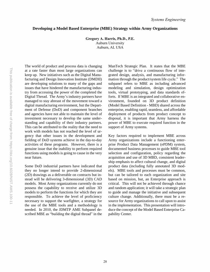
This
public
atio
n is
availa
ble
free o
f charg
e fro
m: h
ttps://d
oi.o
rg/1
0.6
028
/NIS
T.A
MS
.100
-11
Systems Engineering
Developing a Model Based Enterprise (MBE) Strategy within Army Organizations
Gregory A. Harris, Ph.D., P.E.
Auburn University
Auburn, AL USA
The world of product and process data is changing
at a rate faster than most large organizations can
keep up. New initiatives such as the Digital Manu-
facturing and Design Innovation Institute (DMDII)
are developing solutions to many of the gaps and
issues that have hindered the manufacturing indus-
try from accessing the power of the completed the
Digital Thread. The Army’s industry partners have
managed to stay abreast of the movement toward a
digital manufacturing environment, but the Depart-
ment of Defense (DoD) and component branches
and agencies have not able to maintain the level of
investment necessary to develop the same under-
standing and capability of their industry partners.
This can be attributed to the reality that the need to
work with models has not reached the level of ur-
gency that other issues in the development and
fielding of DoD systems achieve in the day-to-day
activities of these programs. However, there is a
genuine issue that the inability to perform required
functions using models is going to cause in the very
near future.
Some DoD industrial partners have indicated that
they no longer intend to provide 2-dimensional
(2D) drawings as a deliverable on contracts but in-
stead will be delivering 3-dimensional (3D) CAD
models. Most Army organizations currently do not
possess the capability to receive and utilize 3D
models to perform the functions for which they are
responsible. To achieve the level of proficiency
necessary to support the warfighter, a strategy for
the use of the MBE tools and a methodology is
needed. In 2010, the JDMTP AME Subpanel de-
scribed MBE as “building the digital thread” in the
ManTech Strategic Plan. It states that the MBE
challenge is to “drive a continuous flow of inte-
grated design, analysis, and manufacturing infor-
mation through the product/system life cycle.” The
subpanel refers to MBE as including advanced
modeling and simulation, design optimization
tools, virtual prototyping, and data standards ef-
forts. If MBE is an integrated and collaborative en-
vironment, founded on 3D product definition
(Model Based Definition - MBD) shared across the
enterprise, enabling rapid, seamless, and affordable
deployment of products from product concept to
disposal, it is important that Army harness the
power of MBE to execute required function in the
support of Army systems.
Key factors required to implement MBE across
Army organizations include a functioning enter-
prise Product Data Management (ePDM) system,
documented business processes to guide MBE tool
selection and configuration, policy regarding the
acquisition and use of 3D MBD, consistent leader-
ship emphasis to affect cultural change, and digital
product data (including fully annotated 3D mod-
els). MBE tools and processes must be common,
but can be tailored to each organization and site
based on mission, but, an Enterprise approach is
critical. This will not be achieved through chance
and random application; it will take a strategic plan
to guide and manage the initiative and subsequent
culture change. Additionally, there must be a re-
source for Army organizations to call upon to assist
in the implementation. This presentation will intro-
duce the concept of the Model Based Enterprise Ca-
pability Center.
28

This
public
atio
n is
availa
ble
free o
f charg
e fro
m: h
ttps://d
oi.o
rg/1
0.6
028
/NIS
T.A
MS
.100
-11
Systems Engineering
The Model Based Enterprise & Systems Engineering: A Black Swan Inspired Perspective
Lisa D. Murphy, Ph.D.
Siemens PLM
Atlanta, GA, USA
In his groundbreaking book The Black Swan, Nas-
sim Taleb introduces the concept of “silent evi-
dence” while discussing cognitive barriers to un-
derstanding highly improbably events. The prem-
ise of silent evidence is that we extrapolate not from
the starting base to today but from today’s outcome
backward, leaving us with a misleading under-
standing of the likelihood of relatively ordinary
events, as we only see today what was successful,
not all the dead-ends, abandoned paths, and solu-
tions not pursued.
By starting to define what information supports the
Model Based Enterprise (MBE) from the product
definition needed for manufacturing, we may expe-
rience the silent evidence fallacy as we move up-
stream into the product development flow. Factors
that make MBE silent evidence significant include
the nature of the product development process that
moves from abstract to concrete, that the level of
uncertainty increases as you go backward into the
development history, that legacy systems often
have different paths, and may have different infor-
mation, different tools, and different data formats.
Notably, even new designs may have elements
starting at different times and maturing at different
rates. And our methodologies for product develop-
ment are seldom pure as the process diagrams sug-
gest, but end up with a mix of approaches that often
remain incompletely documented.
The number and types of models produced is often
difficult for people not involved in managing the
data across the lifecycle to see, and the relationships
between them are not always as direct and linear as
we imagine (a side effect of silent evidence). Mod-
els that used to be expensive and time consuming
to produce are now produced by the thousands ra-
ther than the dozens. Model of a particular type are
no longer only found in a given development phase;
for example, we are seeing the same type of 1-D
physics model being used in the systems engineer-
ing and architecting phase to identify the variables
that matter for optimization so they can be factored
into requirements and passed along to design and
testing activities. This is the equivalent of virtual
integration, which is like starting up the right side
of the Systems Engineering V model from the Sys-
tems Architecting step, rather than from Implemen-
tation.
It has been a promise of MBE (and a goal of engi-
neering and program management) to replace
costly physical tests with models and simulations,
and in many cases, that effort is progressing. For
example, the large, cumbersome, time consuming,
and expensive test called the Iron Bird where phys-
ical instances of all controls are run the same dis-
tance with the same turns and angles they would
have upon installation has now been replaced by
one aircraft manufacturer with a Virtual Iron Bird
simulation model.
Another experience of modeling in MBE related to
testing is less familiar, and that is modeling to sim-
ulate the physical test rig with the test article in it.
While someday it may be possible to do away with
all testing, until then, tests that are costly and dan-
gerous such as fuel cells can have critical cases sim-
ulated by modeling the fuel cells in the test rig, al-
lowing tests to be run faster and safer. These mod-
els are significant in the development process but
are very unlikely to appear in a product-based view
of a product’s models.
The Black Swan concept of silent evidence can help
remind us that the digital thread looks different
moving forward than it does moving backward. As
the nature, types, and uses of models continues to
expand across the system development life cycle,
we will have to take care to avoid a digital tangle.
29

This
public
atio
n is
availa
ble
free o
f charg
e fro
m: h
ttps://d
oi.o
rg/1
0.6
028
/NIS
T.A
MS
.100
-11
Design
STEP for Downstream Consumption
Robert Kirkwood
President, Integration-Guard
Nashua, NH, USA
1. Overview The speaker shows a new technique: Virtual Persis-
tent Identifiers (VPI) to enable sustained integra-
tion (associativity) using STEP files as they are cur-
rently exported by any major CAD vendor. The
technique is shown to work for Casting Design, NC
Programs, FEA-Solids, and FEA-Shells. In each
case the files are exchanged using STEP files as ex-
ported/imported to a variety of CAD applications.
Sustained integration meaning that after the initial
integration, successive iterations only require an in-
cremental effort.
2. Problem statement MBE implementations face a dichotomy regarding
CAD formats. Standard format (e.g. STEP) versus
proprietary formats. Proprietary formats have one
remaining advantage, they are better at staying in-
tegrated over successive design iterations of the
given format. The sooner that advantage has been
neutralized, the sooner we may expect accelerated
adoption of STEP for MBE.
3. Conclusions 1. STEP data as currently exported by every
CAD vendor is already sufficiently to sup-
port sustained integration (associativity).
2. The VPI technique is a new technique to
enable sustained integration. It mitigates
most of the rework trauma associated with
design changes via export/import of neutral
formats.
3. Broken integration (associativity) can be
repaired
4. The ‘E’ in MBE does not mean that a
daunting enterprise-wide implementation
is the only option.
4. Recommendations 1. Manufacturers: Permit vendor compli-
ance with company MBE standards via
STEP. Keep the same functional stand-
ards, just recognize that STEP might sat-
isfy those standards.
2. CAD vendors: Allow that data might be
imported with valid persistent identifiers.
3. CAD vendors: Use the optional attribute
for entity names to export persistent identi-
fiers.
4. All: Educate your executives The issue is IDs/namespaces, not transla-
tion/format
5. All: STEP test parts could include some
cases of successive versions.
6. All: Send challenge cases
5. Supporting information Proprietary integration and point-to-point transla-
tors rely on absolute persistent identifiers on the
various geometric entities. This persistence ena-
bles downstream applications referencing the
model data to stay integrated across successive ver-
sions. Each translation to/from neutral formats like
STEP re-sequences those identifiers with each iter-
ation, rendering the identifiers different from those
in the CAD system and no longer persistent. Vir-
tual persistent identifiers to not attempt to use the
same identifiers as are in the source CAD model.
Instead, the identifiers in each successive version
are mapped back to the originally translated identi-
fiers. Thus, the virtual persistent identifiers present
themselves to the downstream application as being
persistent even though they differ from those in the
originating CAD system.
No engineer wants to be burdened with a new task
managing identifiers in his imported geometry. De-
sign Change Vectors (DCV®) provides notation and
tools allow an engineer to assure virtual persistent
identifiers without significant new effort. Design
Change Vectors allows changes to solid models to
be recognized (subtraction), added (merging), and
created as parallel to other changes.
30

This
public
atio
n is
availa
ble
free o
f charg
e fro
m: h
ttps://d
oi.o
rg/1
0.6
028
/NIS
T.A
MS
.100
-11
Design
Best Practices for Creating MIL-STD-31000A Technical Data Packages (TDP) using (3D)
PDF and STEP Executive Summary
Jerry McFeeters
3D PDF Consortium
Cincinnati, OH, USA
In early 2016, the 3D PDF Consortium began
planning test round two for the 3D PDF Imple-
menter Forum. Early in the planning stages it be-
came apparent that there was a need to extend be-
yond the interoperability testing used by tradi-
tional implementer forums. The Consortium
members wanted to extend the testing to include
the document capabilities of the PDF format. A
quick survey of our membership determined that
the test round should be focused on testing the
ability to create an optimized TDP conforming to
MIL-STD-31000A using the STEP and PDF for-
mats.
In order to prepare for this unique undertaking, the
3D PDF Consortium solicited and received from
PDES, Inc. members, MBD360, Action Engineer-
ing and others who were intimately familiar with
MIL- STD-31000A. After several meetings, the
project scope was defined and the Implementer
Forum was initiated in 2016.
One of the products of this effort is a paper
containing Best Practices for utilizing STEP
and 3D PDF to meet MIL-STD-31000A
standards. The following is an outline of
some of the best practices that are recom-
mended:
• Use Adobe Acrobat DC or Adobe Acro-
bat Reader DC
• Use the Best Standards for 3D
• ISO 32000 (PDF)
• ISO 14739 (PRC)
• ECMA-363, 3rd Edition (U3D)
• Add Structure Using Portfolios and At-
tachments
• Make sure all attachments have a
description
• Use folders to logically organize
attachments
• Use hyperlinks to easily open at-
tachments from inside the portfo-
lio
• Attach CAD and/or STEP file
• While PRC can represent pre-
cise geometry, very few pro-
grams can read this data from a
PDF file
• Workflows that require a precise
CAD model, such as CAM,
should attach a neutral STEP file
and/or native CAD file
• Use JavaScript to support ANSI Y14.41
• Ensure Your Document Is Portable
In conclusion, it was determined that 3D PDF
has unique features that make it an excellent
format for TDP including Collections/Attach-
ments, XFDF support, and JavaScript support.
Recommendations for future rounds of the 3D
PDF Implementer Forum includes the explo-
ration of ways to more tightly integrate 3D
PDF with STEP and other open formats.
31

This
public
atio
n is
availa
ble
free o
f charg
e fro
m: h
ttps://d
oi.o
rg/1
0.6
028
/NIS
T.A
MS
.100
-11
Design
Design Decision Support for MBE with Information Modeling
Douglas Eddy
University of Massachusetts at Amherst
Amherst, MA, USA
Sundar Krishnamurty
University of Massachusetts at Amherst
Amherst, MA, USA
Ian Grosse
University of Massachusetts at Amherst
Amherst, MA, USA
The advancements in additive manufacturing (AM)
and the renaissance of interest in semantic represen-
tation for knowledge management in support of the
product design digital thread advances have led to the
convergence of several main thematic research
scopes to support advanced manufacturing. Along
these lines, ongoing research at the Center for e-De-
sign at UMass Amherst has focused on parallel and
interconnected research themes addressing advance-
ments in the state-of-the-art in AM, focusing on the
development of a product design architecture by in-
clusion of design for AM concepts in an information
model at early design stage. The overall goal of our
project is to model information associated with a
product’s digital thread based on the context and
meaning of such information in a way that facilitates
robust and reliable early design and process deci-
sions. This is a compelling need to address currently
due to the emerging trends in large amounts of data
and information to manage, along with the paradigm
shift in the design of products caused by the ever-
expanding capabilities of additive manufacturing
(AM) processes. Thus, the foundation of this work
is an ontological framework tool and approach that
can both organize design and manufacturing
knowledge in a reusable way that facilitates accurate
early decision-making. Our work introduces con-
cepts related to AM within the existing Manufactur-
ing Service Description Language (MSDL) ontol-
ogy, developed at Texas State to identify process
plans for conventional manufacturing. Our approach
utilizes both part and process information to identify
which combination of processes can produce a de-
sired product. Here, first order logic rules provide
the fundamental basis in the selection of the best-
suited candidate process combination in product re-
alization, thus enabling seamless comparison of AM
with other manufacturing alternatives.
Given the aforementioned paradigm shift in early
product design decisions caused by rapidly improving
AM capabilities, early process selection is now
significantly more consequential. Thus, better and
different methods must decide early based on
available information whether to design a part for AM
or conventional manufacturing. To this end, our
eDesign team at UMass Amherst has developed a
formal decision-based design support system focusing
on the unique differences between design for
manufacturing and design for additive manufacturing.
A salient feature of this approach is its unique ability
to identify inflection points at various production
quantities at which the design of choice can change
from conventional manufacturing to AM and vice-
versa. To test applicability of our approach in a
practical industry environment, we collaborate with
FTL Labs to fill a specific need. Here, the ontological
approach extends to relate CAD-based design features
to metal Direct Energy Deposition AM process
capabilities. The ability to reason upon such
information can provide visual prompts to a designer
in a CAD interfaced software tool about any needs for
design revisions to enable fail proof manufacturing.
Furthermore, a reusable knowledge base can expand
over time to improve process predictability in advance
by enhanced querying and reasoning.
Having developed the conceptual approaches to both
manage the knowledge and utilize that knowledge in
early stage decisions, a remaining challenge concerns
developing the relationship of domain-specific
information in a framework consistent with other
domains. Towards this goal, our future work will
focus on building and connecting established
engineering design domain concepts within the Basic
Formal Ontology to test for consistency and reasoning
capability within this established high-level
knowledge foundation.
32

This
public
atio
n is
availa
ble
free o
f charg
e fro
m: h
ttps://d
oi.o
rg/1
0.6
028
/NIS
T.A
MS
.100
-11
Quality
A Digital Product Realization Revolution
Enabled by Persistent Model-Based Product Characteristics
Curtis W. Brown
Honeywell FM&T*
Kansas City, MO, USA
* Department of Energy’s Kansas City National Security campus operated and managed by Honeywell Federal
Manufacturing & Technologies, LLC under contract number DE-NA0002839.
The purpose of this presentation is to advocate for
those that are on the Model-Based Enterprise
(MBE) journey to travel along a newer route with
the most impactful benefits. The proposed MBE
way must be via the Digital Product Acceptance
Road by means of the “new” Model-Based Prod-
uct Characteristics Bridge. This presentation re-
views various technologies and digital interopera-
bility standards that have arrived or matured that
can revolutionize closed-loop automation within a
MBE business strategy. Specifically, the presenta-
tion promotes the fundamental use of persistent
product characteristics, digitally consumed early
in the product lifecycle and throughout the enter-
prise. The results will transform manufacturing
quality into an agile and valued contributor to the
manufacturing business.
Manufacturing Quality is a customer requirement.
It is not free, nor is it optional; however, it can be
achieved faster, better, cheaper, and smarter with
model-based innovations and standards-based dig-
ital interoperability. Successful manufacturing or-
ganizations recognize that production definition is
a valuable asset for their companies and it is nec-
essary to realize and accept their product. Tradi-
tionally, this was accomplished through 2D static
drawings. Today, this product definition can be
captured as a digital product definition (DPD).
The DPD, aka model-based definition (MBD),
uses a computer-aided design system that fully de-
scribes the shape geometry, metadata, and any
product and manufacturing information (PMI)
necessary to help communicate design intent.
An added advantage for transitioning to MBD is
the significant opportunity to enable the Quality
organization with Model-Based Product Charac-
teristics. A Product Characteristic is a tolerance or
specification applied to a feature or product that
requires verification to assure that the product sat-
isfies requirements. Product Characteristic desig-
nators and their assocated criticality levels are es-
sential for quality and inspection processes. At
present, this information is identified and labeled
just-in-time at the inspection department thru the
process of “ballooning the drawing”. Imagine the
case where this product, manufacturing & inspec-
tion information (PMII), (PMI with model-based
product characteristics), could be defined digitally
and earlier in the lifecycle within the MBD and
persists throughout the enterprise.
A Bill of Characteristics (BoC) is a listing of prod-
uct characteristics required for manufacturing
quality to consume and verify product acceptance.
A complete MBD with PMII can generate a BoC.
Furthermore, the Quality Information Framework
(QIF), an American national standard for digital
interoperability, can effectively represent a model-
based BoC. This model-based BoC information
would drive downstream processes and then allow
for closed loop measurement results to be fed back
to the MBD.
33

This
public
atio
n is
availa
ble
free o
f charg
e fro
m: h
ttps://d
oi.o
rg/1
0.6
028
/NIS
T.A
MS
.100
-11
Quality
Measurement Data Analytics using QIF
Daniel Campbell
Capvidia
Sugar Land, TX, USA
Modern metrology systems consist of a patchwork
of various individual hardware and software
packages, each of which produce massive amounts
of Data. Globalization of industry and vast,
connected supplier networks help to add to the
available amount of Data. With the advent of
Industry 4.0, Data exchange becomes a key part of
industrial processes.
A significant problem we now face is: how does an
organization best leverage all this available Data?
Under current practices, most measurement Data is
not exploited at all, and when it is, it is typically
accomplished via limited, proprietary tools or
complex PLM customizations. To extract
Knowledge about industrial processes from this
vast amount of measurement Data, it must first be
organized into Information with meaning and
context.
There exists a better solution which enables Model
Based Enterprise to fully leverage all its
measurement Data. The context and meaning
behind measurement Data can be provided by the
Quality Information Framework (QIF). QIF is an
XML-based ontology for manufacturing Data, all
built on semantic links to the 3D model. This
solution arose organically via a body of industry
experts ranging from manufacturers (end users),
software vendors, research organizations, and
National Measurement Institutes, all coordinated
by the Dimensional Metrology Standards
Consortium (DMSC).
We showed how software tools can be used to
analyze enormous repositories of measurement
Information in the QIF format. Advanced analytics
and Business Intelligence (BI) methodologies can
be applied towards this Information to understand
trends, root causes, and otherwise increase
manufacturing Knowledge.
34

This
public
atio
n is
availa
ble
free o
f charg
e fro
m: h
ttps://d
oi.o
rg/1
0.6
028
/NIS
T.A
MS
.100
-11
Manufacturing
Applying visual variables to manufacturing data for enhanced decision-making
William Z. Bernstein
National Institute of Standards & Technology
Gaithersburg, Maryland, USA
Since Jacques Bertin’s seminal work on visual var-
iables [1], significant effort has been focused on
mapping visual primitives, such as color, position,
and size, to domain-specific data. To realize an ap-
propriate mapping of visual variables, several de-
velopment procedures are required, including ini-
tial design, prototyping and implementation, inter-
face evaluation with human subjects, as well as in-
tegration into existing computer systems. These
steps are no different when applying the same set of
visualization principles to manufacturing. How-
ever, manufacturing presents unique challenges for
interface developers, such as the connection of dis-
parate databases, complexity in different stake-
holder perspectives and roles, domain-specific data
representations, such as STEP and MTConnect, as
well as the prevalence of significant data uncer-
tainty.
In this presentation, we present three different ef-
forts in applying guiding information visualization
principles to make sense of manufacturing-related
data. The three prototypes include an interactive ex-
ploration tool that allows users to make sense of
manufacturing sensor data (i.e. MTConnect) and its
relationships to design models [2], an interactive in-
terface that allows users to explore relationships of
key performance indicators and their underlying
metrics [3], and a workflow for visualizing the sim-
ilarities of capabilities of manufacturing processes
[4]. All three instances use data elements and rep-
resentations that follow existing standards, such as
ISO 22400 and MTConnect. From these different
visualization prototypes, we have begun to distill
best practices for mapping visual variables to man-
ufacturing data to enhance practical and direct de-
cision-making. An initial set of these “design pat-
terns” focuses on the development of visual analyt-
ics tools to aid in sustainable product design [5].
In the near-term future, we plan to install the Data
& Information Visualization & Exploration (DIVE)
Lab, to more deeply explore aspects related to hu-
man interaction and the evaluation of these inter-
faces. One of the main goals of the DIVE lab is to
demonstrate our visualization prototypes and to test
their utility on a distributed, collaborative system,
where multiple stakeholders are interacting and ex-
ploring a common dataset from different perspec-
tives based on their specific role. A practical use
case here would be a machine operator on the shop
floor detecting a problem at a workstation and then
passing a message to a manager that can interact
with metadata regarding that issue. We plan to im-
plement a testbed version of this use case to explore
new opportunities in developing interface design
guidelines for such distributed collaborative envi-
ronments. Our hope is that these best practices, or
“design patterns”, will quicken the design, proto-
typing and implementation processes of new visu-
alization-based interfaces for data-driven decision-
making.
ACKNOWLEDGEMENTS
The author thanks Kevin Li, Dr. Moneer Helu,
Thomas Hedberg Jr., Allison Barnard Feeney, Dr.
Michael Brundage, KC Morris, and John Horst,
who all contributed to examples presented in this
presentation.
REFERENCES 1. Bertin, J., 1983. Semiology of graphics: diagrams, networks,
maps.
2. Bernstein, W. Z., Hedberg Jr, T. D., Helu, M., Barnard Feeney, A.,
“Contextualizing manufacturing data for lifecycle decision mak-
ing.” International Journal of Product Lifecycle Management. Un-der review.
3. Brundage, M. P., Bernstein, W. Z., Morris, KC, Horst, J. A., “Using
graph-based visualizations to explore key performance indictor re-lationships for manufacturing production systems.” Proceedings
of the CIRP 2017 LCE. To appear.
4. Li, K., Bernstein, W. Z., 2017. “Developing a capability-based similarity metric for manufacturing processes.” Proceedings of the
ASME 2017 MSEC. To appear.
5. Ramanujan, D., Bernstein, W. Z., Ramani, K., 2017. “Design pat-
terns for visualization-based tools in sustainable product design.”
Proceedings of the ASME 2017 IDETC/CIE. To appear.
35

This
public
atio
n is
availa
ble
free o
f charg
e fro
m: h
ttps://d
oi.o
rg/1
0.6
028
/NIS
T.A
MS
.100
-11
Manufacturing
Model-based Visualization for Resistance Spot Welded Assembly Design
Kyoung-Yun “Joseph” Kim, Ph.D., Md. Tarique Hasan Khan,
Fahim Ahmed, and Gary Witus, Ph.D.
NSF Center for e-Design
Wayne State University
Resistance Spot Welding (RSW) is one of the most
common sheet metal welding processes in various
manufacturing industries including the automotive
industry. However, the utilization of the RSW pro-
cess data is still limited due to disconnected welded
assembly design models and associated process
data challenges. Model-based engineering provides
an opportunity to combine and visualize the data
from different lifecycle stages of a welded assem-
bly product in a unified platform.
This study presents a model-based visualization ap-
proach to integrate RSW weldability knowledge
with assembly models. For this study, a semantic
weldability prediction method is used to effectively
predict the weldability of RSW processes, while re-
ducing the data inconsistency effects.
For this purpose, real industry RSW quality da-
tasets are utilized to extract weldability decision
rules with data mining algorithms. An RSW ontol-
ogy, which serves as a formal assembly design
model, is developed and builds a shareable RSW
weldability knowledge.
A CAD system stores the geometric assembly de-
sign information and the STM (SpatioTemporal
Mereotopology) ontology is connected to the de-
sign database in this work. Afterward, welded as-
sembly design and weldability knowledge sets are
extracted from the two ontology-based models and
integrated with a X3DOM data to visualize the as-
sembly design and weldability knowledge. To con-
firm if the unified platform can visualize the 3D as-
sembly models with the predicted weldability, dif-
ferent welded assembly models are tested.
In the demonstration, the visualization platform
successfully distinguishes assembly effects before
and after welding and provides a formal and share-
able assembly design knowledge including welda-
bility.
36
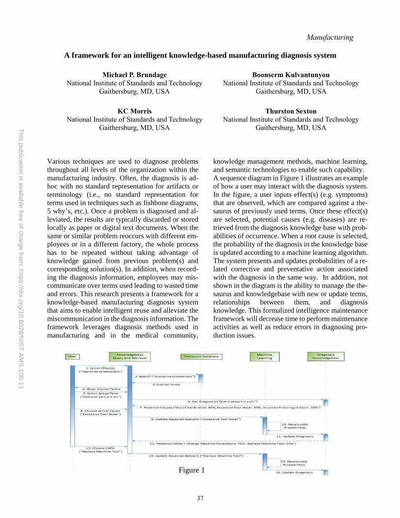
This
public
atio
n is
availa
ble
free o
f charg
e fro
m: h
ttps://d
oi.o
rg/1
0.6
028
/NIS
T.A
MS
.100
-11
Manufacturing
A framework for an intelligent knowledge-based manufacturing diagnosis system
Michael P. Brundage
National Institute of Standards and Technology
Gaithersburg, MD, USA
Boonserm Kulvantunyou
National Institute of Standards and Technology
Gaithersburg, MD, USA
KC Morris
National Institute of Standards and Technology
Gaithersburg, MD, USA
Thurston Sexton
National Institute of Standards and Technology
Gaithersburg, MD, USA
Various techniques are used to diagnose problems
throughout all levels of the organization within the
manufacturing industry. Often, the diagnosis is ad-
hoc with no standard representation for artifacts or
terminology (i.e., no standard representation for
terms used in techniques such as fishbone diagrams,
5 why’s, etc.). Once a problem is diagnosed and al-
leviated, the results are typically discarded or stored
locally as paper or digital text documents. When the
same or similar problem reoccurs with different em-
ployees or in a different factory, the whole process
has to be repeated without taking advantage of
knowledge gained from previous problem(s) and
corresponding solution(s). In addition, when record-
ing the diagnosis information, employees may mis-
communicate over terms used leading to wasted time
and errors. This research presents a framework for a
knowledge-based manufacturing diagnosis system
that aims to enable intelligent reuse and alleviate the
miscommunication in the diagnosis information. The
framework leverages diagnosis methods used in
manufacturing and in the medical community,
knowledge management methods, machine learning,
and semantic technologies to enable such capability.
A sequence diagram in Figure 1 illustrates an example
of how a user may interact with the diagnosis system.
In the figure, a user inputs effect(s) (e.g. symptoms)
that are observed, which are compared against a the-
saurus of previously used terms. Once these effect(s)
are selected, potential causes (e.g. diseases) are re-
trieved from the diagnosis knowledge base with prob-
abilities of occurrence. When a root cause is selected,
the probability of the diagnosis in the knowledge base
is updated according to a machine learning algorithm.
The system presents and updates probabilities of a re-
lated corrective and preventative action associated
with the diagnosis in the same way. In addition, not
shown in the diagram is the ability to manage the the-
saurus and knowledgebase with new or update terms,
relationships between them, and diagnosis
knowledge. This formalized intelligence maintenance
framework will decrease time to perform maintenance
activities as well as reduce errors in diagnosing pro-
duction issues.
Figure 1
37

This
public
atio
n is
availa
ble
free o
f charg
e fro
m: h
ttps://d
oi.o
rg/1
0.6
028
/NIS
T.A
MS
.100
-11
Manufacturing
MBD Supplier Readiness
Jennifer Herron
Action Engineering
Lakewood, CO, USA
Your organization may be “all in” – but what about
your suppliers? Are your suppliers willing to keep
pace or lagging behind? Are you keeping them “in
the loop”? The benefits of Model-Based Definition
(MBD) for your organization cannot be fully real-
ized until your suppliers are operating at your capa-
bility level. Data from ROI of MBD surveys con-
ducted by Action Engineering and Lifecycle In-
sights were shared. The high-level results from sup-
plier survey data are:
• Manufacturing is a no-brainer because having
models is better than only drawings when
building parts
• Reduced time in quoting may yield significant
savings
• How to accomplish digital inspection is still
fuzzy. The following are needed: standard
practices, software tools, training and product
definition that supports digital inspection
• A properly instantiated Digital Enterprise may
lead to production cost savings
The bottom line is: suppliers are ready to receive
model-based data, but the organization is unaware
of the readiness. Often an un-intentional wall is cre-
ated between Engineering and willing suppliers that
prevents the circulation of 3D digital data. Action
Engineering’s CEO discussed methods to open
doors between engineering and suppliers. Many or-
ganizations discover that their source issue is the
lack of resources within Procurement that can ena-
ble the flow of MBD data to willing suppliers.
38

This
public
atio
n is
availa
ble
free o
f charg
e fro
m: h
ttps://d
oi.o
rg/1
0.6
028
/NIS
T.A
MS
.100
-11
Manufacturing
Enabling Automated CNC Measurement on the Digital Thread
William Sobel
System Insights
Emeryville, CA, USA
Martin Hardwick
STEP Tools Inc
Troy, NY, USA
Larry Maggiano
Mitutoyo America
Aurora, IL, USA
John Horst National Institute of Standards and Technology
Gaithersburg, MD, USA
The digital thread will not be based on a single
standard or single vendor solution. It will require
many standards composed into a cohesive model of
production across all dimensions including design,
engineering, planning, scheduling, execution,
measurement, and quality – to name a few. The
challenge will be to harmonize the standards defi-
nitions and models to achieve an open end-to-end
representation of the manufacturing digital thread.
Semantic standards provide the foundation of a
composable software architecture where each
standard provides capabilities that are necessary to
the information flow. We will discuss good soft-
ware architecture practices and how the separation
of responsibilities between STEP, MTConnect and
QIF allows for synergies by exploring an important
use case for manufacturers. The use case is to per-
form accurate and timely dimensional measure-
ments of part features, while those parts are being
produced. Unsurprisingly, the multitude of infor-
mation generated and consumed by metrology
equipment and machine tool software is largely
proprietary, and without expensive translation,
changing software vendors and machine tool ven-
dors can be very costly. The implementation of pro-
prietary software- based on-machine dimensional
metrology has reduced production costs for solu-
tion providers and manufacturers, despite the trans-
lation costs. However, widely adopted digital
thread standards will reduce costs even further.
Therefore, a joint working group between the
MTConnect Institute and the Dimensional Metrol-
ogy Standards Consortium (DMSC) has been
formed to provide a standards-based solution to this
problem.
We describe how we are using the digital thread to
enable the automated, hands free, and real time, val-
idation of MBD design tolerances. The method uses
STEP to describe design requirements, MTConnect
to communicate machining results, and QIF to re-
port inspection results and statistics. The method
relates the three protocols by inserting Universally
Unique Identifiers (UUID’s) into the three types of
files. When a point is touched, an enhanced
MTConnect data stream communicates the UUID
of the relevant tolerance with the sampled point co-
ordinates. When sufficient points have been sam-
pled, the CMM evaluates their coordinates and
sends a report to the rest of the enterprise using QIF.
The CNC and CMM can be at different locations,
and both may be either actual or virtual. The meas-
urements can be made using contact or non-contact
systems, and they can take place on or off the CNC.
The input to the process is a STEP AP242 file with
tolerances on the part model. The output is a QIF
file describing the results of evaluating the toler-
ances for a given part instance. The enabling tech-
nology is a digital twin server that monitors the re-
sults of the manufacturing processes and reports the
coordinates of the sampled points in the design
space of the part.
39
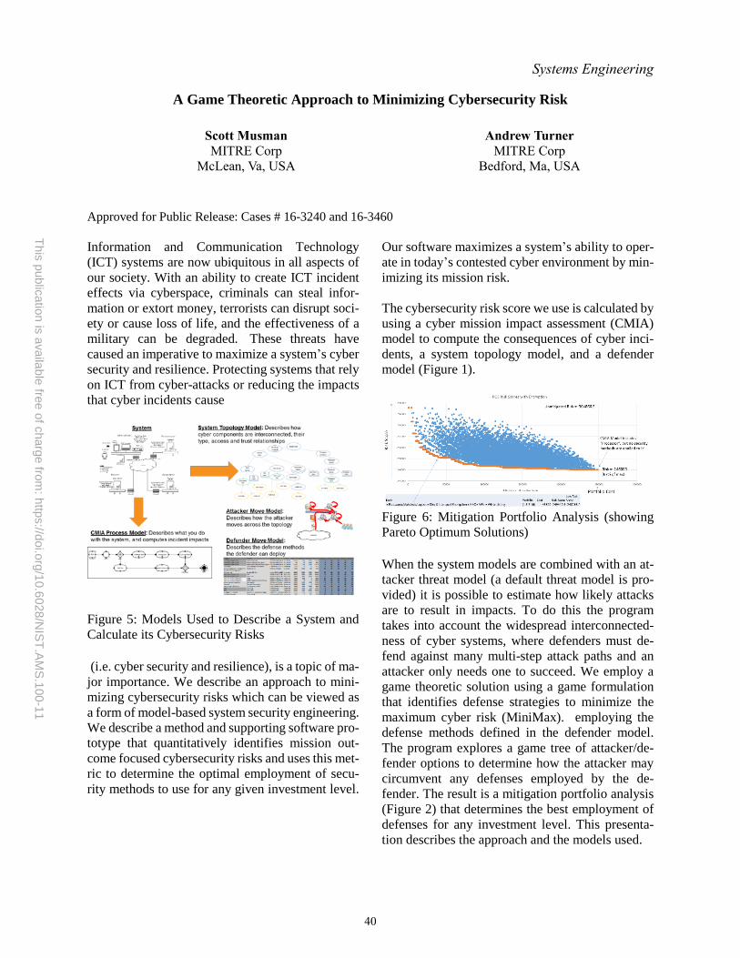
This
public
atio
n is
availa
ble
free o
f charg
e fro
m: h
ttps://d
oi.o
rg/1
0.6
028
/NIS
T.A
MS
.100
-11
Systems Engineering
A Game Theoretic Approach to Minimizing Cybersecurity Risk
Scott Musman
MITRE Corp
McLean, Va, USA
Andrew Turner
MITRE Corp
Bedford, Ma, USA
Approved for Public Release: Cases # 16-3240 and 16-3460
Information and Communication Technology
(ICT) systems are now ubiquitous in all aspects of
our society. With an ability to create ICT incident
effects via cyberspace, criminals can steal infor-
mation or extort money, terrorists can disrupt soci-
ety or cause loss of life, and the effectiveness of a
military can be degraded. These threats have
caused an imperative to maximize a system’s cyber
security and resilience. Protecting systems that rely
on ICT from cyber-attacks or reducing the impacts
that cyber incidents cause
Figure 5: Models Used to Describe a System and
Calculate its Cybersecurity Risks
(i.e. cyber security and resilience), is a topic of ma-
jor importance. We describe an approach to mini-
mizing cybersecurity risks which can be viewed as
a form of model-based system security engineering.
We describe a method and supporting software pro-
totype that quantitatively identifies mission out-
come focused cybersecurity risks and uses this met-
ric to determine the optimal employment of secu-
rity methods to use for any given investment level.
Our software maximizes a system’s ability to oper-
ate in today’s contested cyber environment by min-
imizing its mission risk.
The cybersecurity risk score we use is calculated by
using a cyber mission impact assessment (CMIA)
model to compute the consequences of cyber inci-
dents, a system topology model, and a defender
model (Figure 1).
Figure 6: Mitigation Portfolio Analysis (showing
Pareto Optimum Solutions)
When the system models are combined with an at-
tacker threat model (a default threat model is pro-
vided) it is possible to estimate how likely attacks
are to result in impacts. To do this the program
takes into account the widespread interconnected-
ness of cyber systems, where defenders must de-
fend against many multi-step attack paths and an
attacker only needs one to succeed. We employ a
game theoretic solution using a game formulation
that identifies defense strategies to minimize the
maximum cyber risk (MiniMax). employing the
defense methods defined in the defender model.
The program explores a game tree of attacker/de-
fender options to determine how the attacker may
circumvent any defenses employed by the de-
fender. The result is a mitigation portfolio analysis
(Figure 2) that determines the best employment of
defenses for any investment level. This presenta-
tion describes the approach and the models used.
40