proceedings of the international conference september 20 ...1).pdf · structural health assessment...
TRANSCRIPT

STRUCTURAL HEALTH ASSESSMENT OFTIMBER STRUCTURES
Proceedings of the International Conference September 20-22, 2017 Istanbul, Turkey
Organized by HASAN KALYONCU UNIVERSITY
FACULTY of FINE ARTS and ARCHITECTURE (HKU-GSMF)
& YILDIZ TECHNICAL UNIVERSITY
RESEARCH CENTER for PRESERVATION of HISTORICAL HERITAGE (TA-MIR)
Edited by E. Görün ARUN

The papers herein are published in the form as submitted by the authors after scientific reviewing. Minor changes have been made where obvious errors and discrepancies were met.
Cover Design: Ali Osman Kuruşcu
© Hasan Kalyoncu University Havalimanı Yolu 27410 Şahinbey, Gaziantep, Turkey
Sponsor:
ISBN: 978-605-62703-7-6
Baskı / Printed and Bound:
SHATIS’17 Structural Health Assessment of Timber Structures September 2017
iii
PREFACE
The SHATIS International Conference on Structural Health Assessment of Timber Structures is a meeting organized every two years by countries with a rich history in timber structures and an advanced industrial and academic background in the wood sector. After 3 successful conferences in Portugal, Italy and Poland the 4th edition of the SHATIS in 2017 is in Istanbul, Turkey.
Timber is a gift of nature offering a lot of benefits mainly as a construction material to build vehicles, ships, dwellings and larger structures since early history. It was also used together with masonry to improve masonry’s structural behavior due to its high tensile strength as compared to masonry. Timber roofs and domes covered architectural spaces with masonry walls. There are diverse applications of timber in all ancient cultures all over the world and Anatolia or Asia Minor, has a very rich heritage in this respect. For example, the 2800-years old Gordion Tumulus near Eskişehir-Ankara, which is still standing, is completely in timber. In Central Anatolia, there are medieval mosques built completely in timber. Unfortunately, today most timber dwellings are under the danger of deterioration through the crucial environmental problems of urbanization, natural hazards, ignorance and new demands of the society.
Structural health assessment of timber structures focuses on traditional and contemporary timber structures bridging links between timber architecture and engineering, wood-based industries and the building sector in general. The theme of the conference covers a broad range of areas, including restoration and strengthening, inspection and monitoring, non-destructive testing, experimental results and laboratory testing, analytical and numerical approaches, historical aspects and general methodology, innovative and traditional materials technology, case-studies, codes and guidelines.
SHATIS’17 is organized jointly by the Hasan Kalyoncu University Faculty of Fine Arts and Architecture and Yıldız Technical University Research Center for Preservation of Historical Heritage. This biannually held conference provides an international and interdisciplinary forum for researchers, experts and people from application to exchange their experience and knowledge and disseminate information on preservation of timber structure. Its aim is to enhance knowledge, increase awareness of the current technology and methodology and encourage studies of different disciplines working on timber structures. Contributions of different disciplines from 20 countries present their own experience and ongoing research activities in an interdisciplinary way.
The papers presented in this Conference Proceedings have been chosen through the triple blind evaluation method of the Conference Scientific Committee. We wish to acknowledge and express our sincere gratitude to the Scientific Committee for spending their precious time in reviewing; editing and making significant recommendations to the authors. Special thanks to our sponsors and supporters for their invaluable and generous financial and technical contributions which indeed provide important link between the people in application and academia.
It is hoped that these contributions may be useful for professionals and researchers engaged in the problems of preservation and for those who have interest in the Timber structures. Dr. Görün Arun On behalf of the SHATIS’17 Organizing Committee September 2017

COMMITTEES
INTERNATIONAL ADVISORY COMMITTEE
Zeynep Ahunbay, ICOMOS Turkey Jerzy Jasieńko, Wroclaw University of Technology, Poland Maurizio Piazza, University of Trento, Italy Paulo Lourenço, University of Minho, Portugal Jose Saporiti, National Lab. for Civil Engineering, Portugal
SCIENTIFIC COMMITTEE Zeynep Ahunbay, (ICOMOS Turkey) Ünal Akkemik (Istanbul University, Turkey) Fevziye Aköz (Hasan Kalyoncu University, Turkey) Gülay Altay (Boğaziçi University, Turkey) Ronald Anthony (Anthony & Associates, Inc., CO, USA) Nusret As (Istanbul University, Turkey) Clara Bertolini (Politecnico di Torino, Italy) Jorge Branco (University of Minho, Portugal) Aynur Çiftçi (Yıldız Technical University, Turkey) Thierry Descamps (Université de Mons, Belgium) Milos Drdácký (ITAM, Czech Republic) Andeas Falk (KTH Royal Inst.of Technology, Stockholm) Artur Feio (University Lusíada, Portugal) Massimo Fragiacomo (University of L'Aquila, Italy) Zeynep Eres (Istanbul Technical University, Turkey) Marin Hasan (University of Zagreb, Croatia) Minjuan He (Tongji University, China) Jerzy Jasieńko (Wroclaw Univ. of Technology, Poland) André J.M. Jorissen (Eindhoven Univ.of Technology) Jochen Köhler (Norwegian University of Science and Technology, Norway) Ali Osman Kuruşcu (Yıldız Technical University, Turkey) Paulo B. Lourenço (University of Minho, Portugal) Deniz Mazlum (Istanbul Technical University, Turkey) Federico Mazzolan (Univ. of Naples "Federico II", Italy) María Morales-Conde (University of Seville, Spain) Marius Mosoarca (Timisoara Univ. of Politechnic, Romania) Lina Nunes (National Laboratory for Civil Engineering, Portugal) Maria Adelaide Parisi (Politecnico di Milano, Italy) Maurizio Piazza (University of Trento, Italy) Mariapaola Riggio (Oregon State University, USA) Vladimir Rodríguez (Univ. Politècnica de Catalunya, Spain) José Saporiti (National Laboratory for Civil Engineering, Portugal) Nadide Seçkin (Kırklareli University, Turkey) Hélder Sousa (ISISE, University of Minho, Portugal) Gennaro Tampone (University of Florence, Italy) Roberto Tomasi (Norwegian Univ. of Life Sciences, Norway) Eleftheria Tsakanika (Technical University of Athens, Greece) Meltem Vatan Kaptan (Bahcesehir University, Turkey) Nabi Yüzer (Yıldız Technical University, Turkey)
ORGANISING COMMITTEE Görün Arun (Chair), Hasan Kalyoncu University Nur Urfalıoğlu (Co-chair), Yıldız Technical University Ali Osman Kuruşcu, Yıldız Technical University Özge Bozgeyik, Hasan Kalyoncu University M.Esat Güneş, Yıldız Technical University Tuğrul Tırpan, Hasan Kalyoncu University
iv

CONTENTS
Preface ……………………………………………………………………. iii
Committees ………………………………………………………………… iv
CHAPTER I Historic Timber Structures
Structural Development of Earthquake-Resistant Timber Buildings in the Light of Archaeological Findings in Anatolia – Hülya Dışkaya………………….……………..
3
The Typology of the Historical Timber Bridges of Turkey - Süheyla Yılmaz, Hal-ide Sert, Nurdan Apaydın …………………………………………………………………..
13
The Expansion of Mansard Roofs Accross Europe in 18th Century- Krzysztof Ały-kow, Magdalena Napiórkowska-Ałykow…………………………….……………………
25
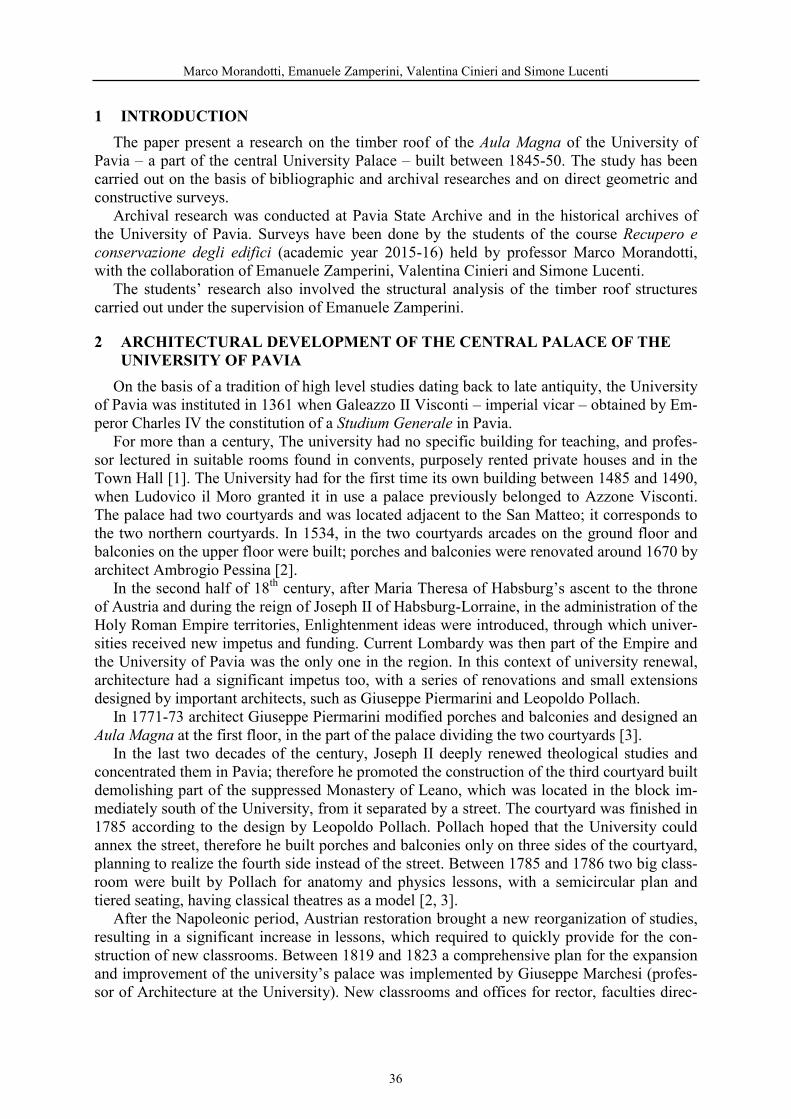
The Timber roof of the Aula Magna of the University of Pavia - MarcoMorandotti, Emanuele Zamperini, Valentina Cinieri, Simone Lucenti…….…………
35
Historical Building with Timber Frame in the Liguria Region: an Inventory Proposal - Anna Bruzzone, Riccardo Forte, Silvia Gelvi, Daniela Pittaluga, FeliceRagazzo, Linda Secondini, Gerolamo Stagno………………………..………………….. 47
Timber Structures in Georgian Cultural Heritage (For Case of Southern Georgia, Region Samtskhe-Javakheti) - A. Tamar Khoshtaria, B. Nino Chachava,C. Malkhaz Lekveishvili ………………………………………………………................... 57
CHAPTER II Traditional Practices
Persian Wooden Structures: Challenges in Repair, Strengthening and Restoration – Mehrdad Hejazi…………………………………………………………………….... 71
The Ottoman House / Evaluation of Structure and Form - Ibrahim Canbulat ………. 83
Sacred Architecture in Montenegro - Case Study: Dobrilovina Monastery - Church of Saint George (1609) and Kučanska Mosque (1797) - Igbala Šabović Kerović,Biljana Šćepanović ………………………………………………………………………...... 95
Surface Coatings of Exposed Timber Elements in the Second Half of the Nineteenth Century in Ottoman Istanbul - Damla Acar ………………………………... 107
Rapid In-site Survey and Assessment Method for Structural Members in Tradi-tional Chinese Timber Structure - Chao Gao, Juan Wang, Qing Shan Yang………… 119
v

The Venetian Floor of the “Bailo Building” in Chalcis, Greece; Deciphering Its Lost Construction Details - Yorgos Kourmadas, Eleftheria Tsakanika, PanagiotaTaxiarchi ……………………………………………………………………………………… 131
Structural and Ornamental Use of Timber in Hagia Triada Church, Ayvalık- Gökhan Okumuş, Nurşah Cabbar, Merve Öztürk, Azime Aladağ, Cansu Ekici, Merve Gökcü, Miray Kısaer, Fuat Gökçe, Nimet Özgönül, Özgün Özçakır ……...…. 143
A Complex Assessment of Historic Roof Structures - Alexandra-Iasmina Keller,Marius Mosoarca……………………….……………………………………………………. 157
CHAPTER III Timber Framed Structures
Timber 2.0: Resilience and Vulnerability of Wood Construction in Earthquakes and Fires - Randolph Langenbach ……………………………………......................... 171
Insight into the Traditional Timber Frame Walls: Herculaneum Evidence Versus Braced Frame Structures in Portugal and in Italy - Stefania Stellacci ........ 185
Historic Timber Frame Structures: A Comparison of Different Constructive Systems and Their Resistance to Seismic Actions - Elisa Poletti, Andreea Dutu,Nicola Ruggieri, Florent Vieux-Champagne ……………………………………..…... 197
Seismic analysis of timber frames and various infills in Romania - Eliza Bulimar,Andreea Dutu, Daniel Ioan Dima, Razvan Ietan …………………………………….. 207
Construction Systems of Timber Structures in China and Italy: A First Comparison of Conservation Approaches - Shiruo Wang, Maria Rosa Valluzzi,Claudio Modena …………………………………………………………………..…….... 219
An Eighteenth Century Postal Palace of August III in Kutno – Its Original Architecture and Half-Timbered Frame Construction - Ulrich Schaaf ……………. 231
Evaluation of the Constructive Material Features of a Medieval Timber Framing in Arquata Scrivia “Gotic House”, Francesco Saverio Fera, Lucia Macario, Ni-cola Ruggeri, Gerolamo Stagno, Rita Vecchiattini ………………………………..…. 243
CHAPTER IV Experimental Methods and Tests
Assessment of Timber Structures. Looking to the past to plan the future - JoseSaporiti Machado ………………………………………………………..………………. 257
Yenikapı Byzantine Shipwrecks, Istanbul-Turkey - Ufuk Kocabaş …………….... 269
Estimation of Timber Members' Properties Combining Direct and Indirect Information: Two Applications - Dulce Henriques, Ana Cândido ……..………….. 281
vi

Characteristics and Evaluation of Termite Damage to Historical Wooden Buildings in South Korea - Kim Si Hyun …………………………………………...…. 293
Damage Evolution in Wood under Tensile Loading Monitored by Acoustic Emission - Imen Yahyaoui, Marianne Perrin, Xiaojing Gong, Hang Li …………. 301
Monitoring Method Analysis for Effective Measure of Wooden Architectural Heritage - Ha Na Lee, A. Dai Whan, K. Hwan Chol, Y. Hyun Woo, K. Dong Yeol 313
Residual Life Prediction of Ancient Timber Components Based on Cumulative Damage Model: A Literature Review - Wang Zhongcheng, Na Yang ………..…… 321
Assessment of the Jupiter Joint‘s In-plane and Out-of-plane Mechanical Behav-iour under Combined Actions - Elena Perria, Martin Kessel, Michele Paradiso,Mike Sieder ……………………………………………………………………………..…. 329
Indirect Sonic Stress Waves Method to Predict the Cross-Sectional Variation of Bending Modulus of Elasticity of a Timber Member - Maria Jesus MoralesConde, Jose Saporiti Machado ………………………………………………………….. 341
Moisture Content Monitoring in Glulam Structures by Embedded Sensors - HangLi, Marianne Perrin, Florent Eyma, Xavier Jacob, Vincent Gibiat ………….…..… 349
The Analysis of the Long-Term Structural Health Monitoring of a Typical Ancient Tibetan Building - Tin Guo, Na Yang ……………………………………… 361
Strengthening of Traditional Buildings with Slim Panels of Cross-Laminated Timber (CLT) - Anders Bjørnfot, Francesco Boggian, Anders Steinsvik Nygård,Roberto Tomasi …………………………………………………………………….……… 369
CHAPTER V Structural Evaluation and Safety Assessment
Safety Assessment and Strengthening of Ica Cathedral In Peru: The Hidden Timber Skeleton - Paulo B. Lourenço, Maria Pia Ciocci, Satyadhrik Sharma ….... 383
Experimental and Numerical Investigations on Timber-Concrete Connections with Inclined Screws - Beatrice Berardinucci, Simona Di Nino, Amedeo Gregori, Mas-simo Fragiacomo, Franco Moar ……………………………………………………….... 395
Assessment of the Structural Performance of a Norwegian Historic Timber Structure: Værnes Church - Filippo Frontini, Jan Siem, Dag Nilsen…………..……. 407
Seismic Performance Evaluation of Traditional Quincha Panels using the Capacity Spectrum Method - Daniel Torrealva, Roberto Marcio Silva ……………………..… 419
vii
Problems of Durability of Timber Structures Under Use Class 2 - Alfonso Lozano,David Lorenzo, Mar Alonso, Josu Benito ……………………………….……………… 431
Structural Assessment of Timber Hanging Truss in Salt Magazines in Pag - JurajPojatina, David Anđić, Hrvoje Turkulin, Marin Hasan……………………………….. 441
A Database Construction Tool for Seismic Vulnerability Assessment of Timber Roof Structures - Maria Adelaide Parisi, Chiara Tardini, Davide Vecchi …………. 451
Effect of Queti-Inclination on Mechanical Properties of Typical Tibetan Timber Beam-Column Joint - Qin Shujie, Na Yang ……………………………..……………… 463
Seismic Behavior of a Two-Story House from the Historical Center of Lima – A Mixed System Adobe Masonry and Quincha System - Daniel Torrealva, Arturo E.Santa-Maria ……………………………………………………………………………..….. 473
Predicting Mechanical Properties of Timber Elements by Regression Analysis Considering Multicollinearity of Non-Destructive Test Results - Hélder S. Sousa,Jorge M. Branco, José Saporiti Machado and Paulo B. Lourenço ……………….…. 485
Numerical Modelling of the Cyclic Behaviour of Timber-Framed Structures using OpenSees - Relja Lukic, Elisa Poletti, Graça Vasconcelos, Hugo Rodrigues ……… 495
Load-Bearing Capacity of Historic Timber with Focus on the Wood Corrosion - Wolfgang Rug, Gunter Linke ………………………………………………………..…….. 505
Determination of Bearing Strength of Wood Peg Connection - Gi Young Jeong,Jin Hyuk Kong ………………………………………………………………………………. 517
CHAPTER VI Intervention, Restoration and Prevention
In Progress Restoration of the Golden Palace Monastery in Mandalay, Myanmar - Stephen J. Kelley ……………………………………………………………………………. 525
Restoration Principles, Design and Practice – a Case Study from Safranbolu, the UNESCO World Heritage City - Ibrahim Canbulat …………………………….......... 537
Recent Developments in Remedial and Non-Pressure Wood Protection Systems: Boron-based Compounds - S. Nami Kartal, Evren Terzi ……………………………... 549
Conservation and Restoration of Brazilian Colonial Architecture - Benedito Tadeude Oliveira, Vanessa Araujo Braide ………………………………………………….….. 559
Reconstruction of a Wooden "Polish Manor" with the Use of Solid Wood Layered Floors - Anna Rozanska, Anna Policinska - Serwa, Wojciech Korycinski, PiotrBeer …………………………………………………………………………………………… 569
viii

Numerical Study on the In-plane Behaviour of Existing Timber Diaphragms Strengthened with Diagonal Sheathing - Ermes Rizzi, Mirko Capovilla, IvanGiongo, Maurizio Piazza …………………………………………………………….…….. 581
Single Step Joint Design and Reinforcement with Self-Tapping Screws - MaximeVerbist, Jorge Branco, Elisa Poletti, Thierry Descamps, Paulo Lourenço ….……… 593
Author Index ……………………………………………………………………………605
ix

CHAPTER I
HISTORIC TIMBER STRUCTURES

STRUCTURAL DEVELOPMENT OF EARTHQUAKE-RESISTANT TIMBER BUILDINGS IN THE LIGHT OF ARCHAEOLOGICAL
FINDINGS IN ANATOLIA
Hülya Dışkaya
Mimar Sinan Fine Arts University, [email protected]
Keywords: Structure, Earthquake-Resistant, Timber, Archaeological Finds, Anatolia
Abstract
Turkey has undergone numerous devastating earthquakes due to being located on the Mediterra- nean Seismic Belt throughout its history. The date of transition to a settled order in Anatolian peninsula bases on approximately 13.000 years and it has been a cradle for many cultures and civilizations. These cultures understood the seismic character of the country and developed earthquake-resistant buildings with timber which was a lightweight and ductile material in this trial and error platform.
The descriptions on archaeological finds have been an important factor in the reflection of his- torical chronology of past life styles and structural forms. This could cover a wide area such as hieroglyph and cuneiform texts and weapons in hunting rituals, musical instruments in religious or wedding ceremonies, architectural spaces and structural definitions.
Turkey has its specific kind of timber buildings that helped the people to survive the destructive earthquakes. In this research it is seen that these buildings have become more earthquake- resistant in terms of both structural and architectural design in the course of time. Understanding these structures is important for reaching the past knowledge and future production of timber buildings.
In this paper, the historical development of earthquake-resistant timber building pro- duction in Anatolia is investigated. Firstly the seismic structure of, forestry lands and timber residential placements were researched in relation to each other. Accordingly, the interrelationship between sustainable development process of plan types and structural systems were analysed under the light of archaeological finds. Consequently the structural characteristics that render a traditional timber building earthquake-resistant were studied and the most advanced structural systems were demonstrated in connection with their predecessors.
3

Hülya Dışkaya
1 INTRODUCTION
Turkey has undergone numerous devastating earthquakes due to being located on the Medi- terranean Seismic Belt throughout its history. The date of transition to a settled order in Anato- lian peninsula bases on approximately 13.000 years from today and it has been a cradle for many cultures and civilizations. These cultures not only discovered the tools necessary for sus- taining their lives but they also understood the seismic character of the country and developed earthquake-resistant buildings with timber which was a lightweight and ductile material in this trial and error platform.
Although the highly inflammable timber material caused several fires that have wiped out thousands of houses, even whole districts and cities, timber material is always used as a lacing element in the structures against earthquakes throughout the history.
Aware of being an earthquake country, timber construction was enforced by Ottoman Period Building Codes (Ebniye Regulations) for rescuing human lives [1]. After the invention of rein- forced concrete in the middle of 1950s, construction with the wood was abandoned. Multi- storey modern buildings were constructed in and around the cities, causing occupants of timber buildings to leave their dwellings in favour of concrete ones. The timber houses were left to their fate and due to lack of care and improper restorative interventions, these buildings lost their structural integrity.
Although the usage information cannot be accessed directly, because of the timber is a per- ishable material, its usage could be understood with the help of archaeological excavations as well as definitions on cuneiform tablets, clay models and drawings on various pots [2].
2 SEISMIC STRUCTURE OF ANATOLIA
The continuous movements of different continental plates have led to the formation of many fault lines in Anatolia. The motion of Arabian Plate causes the majority of earthquakes [3]. The 92% of the land of Turkey is located in earthquake zones [4]. The North Anatolian Fault Line stretches from Anatolia split into three parts in the Sea of Marmara [5] and from there to Greece and Italy (Fig.1) [3].
Figure 1: Fault lines and terrestrial plates in Turkey Figure 2: Forest Map of Turkey (Celep, Z., Kumbasar, N.) (T.R. Ministry of Environment and Forestry)
2.1 Relationship between fault lines, forests and timber structure settlements The abundance of material that can easily be found around was one of the most effective
factors for determining the traditional structure type as well as the fault lines. The dense forests constitute was an important data for using timber material to construct traditional buildings on the fault lines (Fig. 3) [2].
4
Structural Development of Earthquake-resistant Timber Buildings in the Light of Archaeological finds in Anatolia
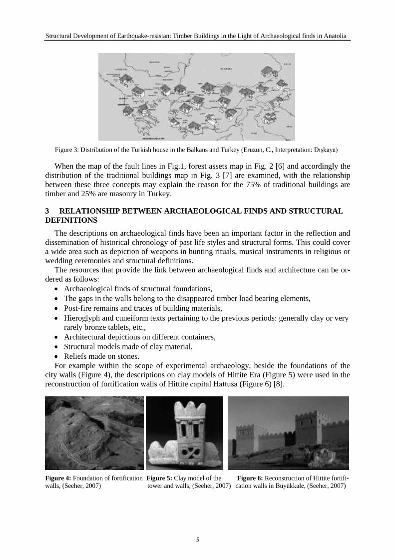
Figure 3: Distribution of the Turkish house in the Balkans and Turkey (Eruzun, C., Interpretation: Dışkaya)
When the map of the fault lines in Fig.1, forest assets map in Fig. 2 [6] and accordingly the distribution of the traditional buildings map in Fig. 3 [7] are examined, with the relationship between these three concepts may explain the reason for the 75% of traditional buildings are timber and 25% are masonry in Turkey.
3 RELATIONSHIP BETWEEN ARCHAEOLOGICAL FINDS AND STRUCTURAL DEFINITIONS
The descriptions on archaeological finds have been an important factor in the reflection and dissemination of historical chronology of past life styles and structural forms. This could cover a wide area such as depiction of weapons in hunting rituals, musical instruments in religious or wedding ceremonies and structural definitions.
The resources that provide the link between archaeological finds and architecture can be or- dered as follows:
Archaeological finds of structural foundations, The gaps in the walls belong to the disappeared timber load bearing elements, Post-fire remains and traces of building materials, Hieroglyph and cuneiform texts pertaining to the previous periods: generally clay or very
rarely bronze tablets, etc., Architectural depictions on different containers, Structural models made of clay material, Reliefs made on stones.
For example within the scope of experimental archaeology, beside the foundations of the city walls (Figure 4), the descriptions on clay models of Hittite Era (Figure 5) were used in the reconstruction of fortification walls of Hittite capital Hattuša (Figure 6) [8].
Figure 4: Foundation of fortification Figure 5: Clay model of the Figure 6: Reconstruction of Hittite fortifi- walls, (Seeher, 2007) tower and walls, (Seeher, 2007) cation walls in Büyükkale, (Seeher, 2007)
5

Hülya Dışkaya
3.1 Architectural features of the houses correlation between archaeological findings The room has always been the most important part of the Turkish house - like the early ma-
sonry settlements or tents of nomadic tribes’ examples, where the main life activities like eat- ing, sleeping and having bath were happening.
The data of the archaeological excavations could give some important knowledge for clari- fying the plan type evolution in Anatolia. The correlation between the plans of early Bronze Age settlements in Beycesultan (Fig.7) [9] and the early 17th Century Halil Ağa Mansion in Bursa-Mudanya (Fig.8) [10] could help to understand the developmental transformation in plan types after approximately 7000 years.
Figure 7: Bronze Age House in Beycesultan Figure 8: Halil Ağa House (Eldem, S. H. E., Inter- (Naumann, R.) pretation: Dışkaya)
Sofa was the manufacturing area of the house where the whole productions of the home were made and the rooms were opening to it. Turkish house plan types have been classified according to their sofa types, these are: without sofa, with outer sofa, with inner sofa and with central sofa. The plans of the houses are classified also according to have an iwan (eyvan) and a kiosk (köşk) or having both. The interpretation of sofa classification according to their plan development process in time can be monitored in Table 1 [11].
Table 1: Plan Types of Various Turkish House Samples, (Eldem, 1984, Interpretation: Dışkaya)
3.2 Structural features of the houses correlation between archaeological finds The structural features of the buildings were changing depending on their geographical
placement, climate conditions and material choice in historical evaluation process. Even if a structure that is constructed with entirely of wood which is not accessed today, it
can be said that the main structural system was formed on stone foundations with mud brick walls composed with timber load bearing elements according to the excavations.
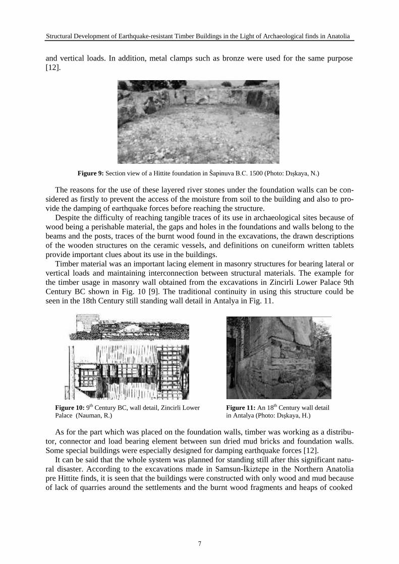
In the formation of foundations the small river stones were used as layers and the orthostatic foundation walls were built on top of them as large cut stones (Figure 9). These cut stones were connected to each other in a unique and intricate way to increase their resistance to horizontal
6
Structural Development of Earthquake-resistant Timber Buildings in the Light of Archaeological finds in Anatolia
and vertical loads. In addition, metal clamps such as bronze were used for the same purpose [12].
Figure 9: Section view of a Hittite foundation in Šapinuva B.C. 1500 (Photo: Dışkaya, N.)
The reasons for the use of these layered river stones under the foundation walls can be con- sidered as firstly to prevent the access of the moisture from soil to the building and also to pro- vide the damping of earthquake forces before reaching the structure.
Despite the difficulty of reaching tangible traces of its use in archaeological sites because of wood being a perishable material, the gaps and holes in the foundations and walls belong to the beams and the posts, traces of the burnt wood found in the excavations, the drawn descriptions of the wooden structures on the ceramic vessels, and definitions on cuneiform written tablets provide important clues about its use in the buildings.
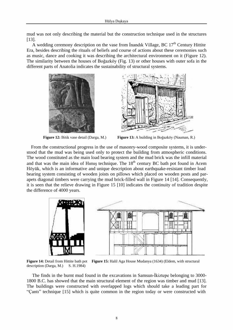
Timber material was an important lacing element in masonry structures for bearing lateral or vertical loads and maintaining interconnection between structural materials. The example for the timber usage in masonry wall obtained from the excavations in Zincirli Lower Palace 9th Century BC shown in Fig. 10 [9]. The traditional continuity in using this structure could be seen in the 18th Century still standing wall detail in Antalya in Fig. 11.
Figure 10: 9th Century BC, wall detail, Zincirli Lower Figure 11: An 18th Century wall detail Palace (Nauman, R.) in Antalya (Photo: Dışkaya, H.)
As for the part which was placed on the foundation walls, timber was working as a distribu- tor, connector and load bearing element between sun dried mud bricks and foundation walls. Some special buildings were especially designed for damping earthquake forces [12].
It can be said that the whole system was planned for standing still after this significant natu- ral disaster. According to the excavations made in Samsun-İkiztepe in the Northern Anatolia pre Hittite finds, it is seen that the buildings were constructed with only wood and mud because of lack of quarries around the settlements and the burnt wood fragments and heaps of cooked
7
Hülya Dışkaya
mud was not only describing the material but the construction technique used in the structures [13].
A wedding ceremony description on the vase from İnandık Village, BC 17th Century HittiteEra, besides describing the rituals of beliefs and course of actions about these ceremonies such as music, dance and cooking it was describing the architectural environment on it (Figure 12). The similarity between the houses of Boğazköy (Fig. 13) or other houses with outer sofa in the different parts of Anatolia indicates the sustainability of structural systems.
Figure 12: vase detail (Darga, M.) Figure 13: A building inBoğazköy (Nauman, R.)
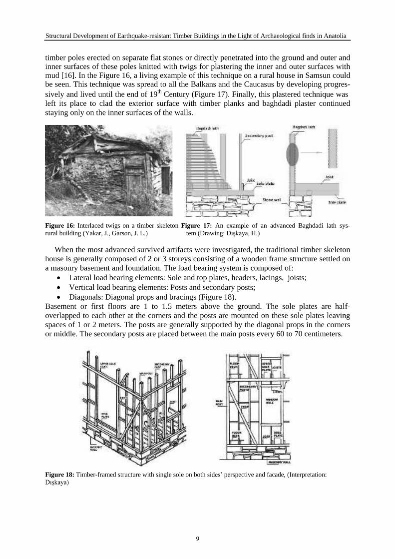
From the constructional progress in the use of masonry-wood composite systems, it is under- stood that the mud was being used only to protect the building from atmospheric conditions. The wood constituted as the main load bearing system and the mud brick was the infill material and that was the main idea of Hımış technique. The 18th century BC bath pot found in AcemHöyük, which is an informative and unique description about earthquake-resistant timber load bearing system consisting of wooden joists on pillows which placed on wooden posts and par- apets diagonal timbers were carrying the mud brick-filled wall in Figure 14 [14]. Consequently, it is seen that the relieve drawing in Figure 15 [10] indicates the continuity of tradition despite the difference of 4000 years.
Figure 14: Detail from Hittite bath pot Figure 15: Halil Aga House Mudanya (1634) (Eldem, with structural description (Darga, M.) S. H.1984)
The finds in the burnt mud found in the excavations in Samsun-İkiztepe belonging to 3000- 1800 B.C. has showed that the main structural element of the region was timber and mud [13]. The buildings were constructed with overlapped logs which should take a leading part for “Çantı” technique [15] which is quite common in the region today or were constructed with
8
Structural Development of Earthquake-resistant Timber Buildings in the Light of Archaeological finds in Anatolia
timber poles erected on separate flat stones or directly penetrated into the ground and outer and inner surfaces of these poles knitted with twigs for plastering the inner and outer surfaces with mud [16]. In the Figure 16, a living example of this technique on a rural house in Samsun could be seen. This technique was spread to all the Balkans and the Caucasus by developing progres- sively and lived until the end of 19th Century (Figure 17). Finally, this plastered technique wasleft its place to clad the exterior surface with timber planks and baghdadi plaster continued staying only on the inner surfaces of the walls.
Figure 16: Interlaced twigs on a timber skeleton Figure 17: An example of an advanced Baghdadi lath sys- rural building (Yakar, J., Garson, J. L.) tem (Drawing: Dışkaya, H.)
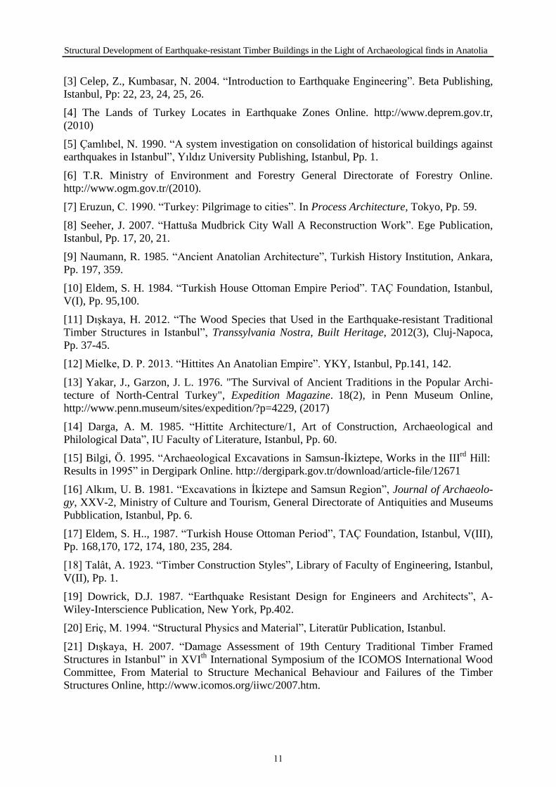
When the most advanced survived artifacts were investigated, the traditional timber skeleton house is generally composed of 2 or 3 storeys consisting of a wooden frame structure settled on a masonry basement and foundation. The load bearing system is composed of:
Lateral load bearing elements: Sole and top plates, headers, lacings, joists;Vertical load bearing elements: Posts and secondary posts;Diagonals: Diagonal props and bracings (Figure 18).
Basement or first floors are 1 to 1.5 meters above the ground. The sole plates are half-overlapped to each other at the corners and the posts are mounted on these sole plates leaving spaces of 1 or 2 meters. The posts are generally supported by the diagonal props in the cornersor middle. The secondary posts are placed between the main posts every 60 to 70 centimeters.
Figure 18: Timber-framed structure with single sole on both sides’ perspective and facade, (Interpretation: Dışkaya)
9

Hülya Dışkaya
The posts, props and the secondary posts are tied together with the lintels (hatıl) or lacings (kuşak) [17]. Heights of the structures are determined by building regulations (ebniye ni- zamnameleri) and the heights of the storeys were 3.50 to 3.70 meters. Thebuilding’s internal skeleton system is generally enclosed by bagdadi laths. The outside of the building were plas- tered or covered with boarding planks depending on the region. This boarding system wraps around the building and acts like a curtain wall. Structure projections consist of prop, console with joist and overlapped console joists and its load was transferred to the main posts by diag- onal braces. Construction of the roof was simple. Generally, a setting roof was constructed. The roof bindings were placed with 1.5, 2.0 or 2.5 meter spaces between them while the purlins were placed every 1.5 to 2.0 meters apart. The ridge joists were placed directly on the roof post and the rafters were placed on the purlin every 30 to 40 centimetres [17]. During the 19th century, the bottom surfaces of the eaves [18] began to be covered. Wrought nails were used inthe connections of node points. In the short term loadings these iron nails [19], has the same ductile manner [20], with the timber material that was used in the construction [21].
4 CONCLUSIONS
Turkey is a country that has its specific kind of timber buildings that helped the people tosurvive the destructive earthquakes. Depending on a variety of reasons like fire, lack of care these examples decreased in the course of time. Although leaving these buildings in favour ofmore modern concrete ones, the features having the timber buildings as well as timber material did not lose their importance as living examples produced in this geography.
In this research it is seen that these buildings not had been developed only in a structural way but they also have become more earthquake-resistant in terms of architectural design and plan type.
The continuity of the information transmission and transfer undoubtedly has contributed tothe perfection of earthquake-resistant timber buildings both architecturally and structurally inthe course of time. The 19th century timber frame system Turkish house should be the result ofa mixture of various timber structure productions from raised flooring house inŠapinuva totimber post system linked with twigs and plastered over with mud inİkiztepe-Samsun and di- agonal propped houses of Boğazköy-Hattuša-Çorum.
Understanding these structures that proved themselves with the structural systems, durabil- ity and strength of their materials against time is important for reaching the past knowledge and future production of timber buildings.
5 ACKNOWLEDGEMENTS
I would like to thank the Hittitologist and photographer Neslihan Dışkaya for contributing this paper with important information about Anatolian Archaeology and for kindly sharing the photographs from her personal archive.
REFERENCES
[1] Cezar, M. 2002.“Ottoman Capital City Istanbul”. Erol Kerim Aksoy Foundation, Istanbul, Pp. 327-380.
[2] Dışkaya, H. 2006.“Historical Development of Traditional Earthquake-Resistant Construc- tion Techniques in Anatolia”. Proceedings of the V. Conference onSAHC’2006, V.1. Edited byLourenco, P. B. , Roca, P., Modena, C., Agrawal, S. MacMillan Advanced Research Series. Delhi, Pp:167-174.
10
Structural Development of Earthquake-resistant Timber Buildings in the Light of Archaeological finds in Anatolia
[3] Celep, Z., Kumbasar, N. 2004.“Introduction to Earthquake Engineering”. Beta Publishing,Istanbul, Pp: 22, 23, 24, 25, 26.
[4] The Lands of Turkey Locates in Earthquake Zones Online. http://www.deprem.gov.tr,(2010)
[5] Çamlıbel, N. 1990.“A system investigation on consolidation of historical buildings against earthquakes in Istanbul”, Yıldız University Publishing, Istanbul, Pp. 1.
[6] T.R. Ministry of Environment and Forestry General Directorate of Forestry Online.http://www.ogm.gov.tr/(2010).
[7] Eruzun, C. 1990. “Turkey: Pilgrimage to cities”. In Process Architecture, Tokyo, Pp. 59.
[8] Seeher, J. 2007.“Hattuša Mudbrick City Wall A Reconstruction Work”. Ege Publication, Istanbul, Pp. 17, 20, 21.
[9] Naumann, R. 1985. “Ancient Anatolian Architecture”, Turkish History Institution, Ankara, Pp. 197, 359.
[10] Eldem, S. H. 1984.“Turkish House Ottoman Empire Period”. TAÇ Foundation, Istanbul, V(I), Pp. 95,100.
[11] Dışkaya, H. 2012.“The Wood Species that Used in the Earthquake-resistant Traditional Timber Structures inIstanbul”, Transsylvania Nostra, Built Heritage, 2012(3), Cluj-Napoca,Pp. 37-45.
[12] Mielke, D. P. 2013. “Hittites An Anatolian Empire”. YKY, Istanbul, Pp.141, 142.
[13] Yakar, J., Garzon, J. L. 1976. "The Survival of Ancient Traditions in the Popular Archi- tecture of North-Central Turkey", Expedition Magazine. 18(2), in Penn Museum Online,http://www.penn.museum/sites/expedition/?p=4229, (2017)
[14] Darga, A. M. 1985.“Hittite Architecture/1, Art of Construction, Archaeological and Philological Data”, IU Faculty of Literature, Istanbul, Pp. 60.
[15] Bilgi, Ö. 1995.“Archaeological Excavations in Samsun-İkiztepe, Works in the IIIrd Hill:Results in1995” in Dergipark Online. http://dergipark.gov.tr/download/article-file/12671
[16] Alkım, U. B. 1981.“Excavations in İkiztepe and Samsun Region”, Journal of Archaeolo- gy, XXV-2, Ministry of Culture and Tourism, General Directorate of Antiquities and Museums Pubblication, Istanbul, Pp. 6.
[17] Eldem, S. H.., 1987. “Turkish House Ottoman Period”, TAÇ Foundation, Istanbul, V(III),Pp. 168,170, 172, 174, 180, 235, 284.
[18] Talât, A. 1923.“Timber Construction Styles”, Library of Faculty of Engineering, Istanbul, V(II), Pp. 1.
[19] Dowrick, D.J. 1987.“Earthquake Resistant Design for Engineers and Architects”, A- Wiley-Interscience Publication, New York, Pp.402.
[20] Eriç, M. 1994. “Structural Physics and Material”, Literatür Publication, Istanbul.
[21] Dışkaya, H. 2007. “Damage Assessment of 19th Century Traditional Timber FramedStructures inIstanbul” in XVI th International Symposium of the ICOMOS International WoodCommittee, From Material to Structure Mechanical Behaviour and Failures of the Timber Structures Online, http://www.icomos.org/iiwc/2007.htm.
11

12
THE TYPOLOGY OF THE HISTOR ICAL TIMBER BRIDGES OF TURKEY
S.Yılmaz1, H.Sert1 N.Apaydın1
1 Historical Bridges Division, Department of Structures, General Directorate of Highways, Ankara, Turkey
Keywords: Conservation, preservation, historical timber bridges, typology.
Abstract
Timber was probably the first material used by humans to construct a bridge structures since Ne-olithic era. The oldest man-made bridges were probably were done by laying tree trunks across streams in girder fashion. Later, many timber bridges were built all over the world, using many variants of beams, cantilevers, trusses and arches.
In Turkey, The Hittite Bridge in Ambarlıkaya near Hattuşa, the capital city of the Hittite Empire,
today in Çorum Province, known as the oldest bridge constructed with wooden beams laid across
Ambarlıkaya gorge. In Turkey, historical tim-ber bridges belonging to ancient times couldn’t
survive till now while only a few belonging to 19thcentury are still standing and still reflect the materials and construction technologies of thepast. Those bridges, therefore, are very valuable and deserve to be discovered in terms of their technical specifications.
The present study is an effort to classify the historical timber bridges in Turkey that have survived up until today. To do that, the study has started with literature survey about the historical development and classification of timber bridges throughout the history in the world. By using that knowledge, the historical timber bridges in Turkey, were classified in groups depending on their construction technologies. Discovery of the visible and invisible tech-nical features of historical timber bridges has vital importance for transferring that knowledge to conservation practitioners for repairs and maintenance of these bridges. This research is, in fact, a useful and effective attempt to transfer that knowledge achieved in the past to young genera-tions.
13

S.Yılmaz, H.Sert, N.Apaydın
1 INTRODUCTION
Anatolia which has witnessed the development of various civilizations for centuries was covered with road network to meet the communicational, militaristic and commercial re-quirements of the societies. Within this process, as part of the transportation system the bridg-es have turned out to be the supplementary elements of the cultural history as beneficial structures serving for commercial, economic, militaristic, social and cultural purposes.
In addition to constructing new roads and bridges, improving the existing historical bridges through maintenance and repair is also among the primary duties of the General Directorate of Highways. According to the Division of Historical Bridges' Inventory (as of December 2016), it has been observed that there exists a total of 1948 each bridges in our country the majority of which is located on 1st degree seismic zone, dating back to Hittite Period(1), Urartian(1), Roman(142), East Roman(26), Seljuk(160), Ottoman (1509) and Early Republican(105) Peri-ods with 316 bridges dating back to Ottoman Period, abroad the majority of which is located in Bosnia and Herzegovina. 1948 ea bridges are classified in accordance with their construc-tion technique as follows: Stone(1834), Wooden(38), Iron (34), Reinforced Concrete (42) [1], [2].
Timber was probably the first material used by humans to construct a bridge structures since Neolithic era. The oldest man-made bridges were probably were done by laying tree trunks across streams in girder fashion. Later, many timber bridges were built all over the world, using many variants of beams, cantilevers, trusses and arches.
2 HISTORICAL DEVELOPMENT AND CLASSIFICATION OF TIMBER BRIDGES IN THE WORLD
The papers will only be published if the author participates in the conference. At least one of the authors must register and pay his/her registration fee before the deadline for their paper to be included in the final program of the Conference. Once a paper has been uploaded, it will not be possible to edit the document. Timber has been widely used as construction material from the first examples of bridge building to the modern designs. There are several ad-vantages of timber as a construction material. It has a high strength to weight ratio; it is natu-ral, renewable and sustainable, has low embodied energy content during manufacture; and with regular surface treatments and protection, longer service life can be ensured easily. It is also ideal for the applications where aesthetics and beauty is important [3].
Since the primitive ones built with tree trunks to the modern examples built with industrial timber, timber bridges have been built in several structural types; beam, cantilever, suspended, arch, truss, and in hybrid form such as trussed arches. Timber bridges are generally built for pedestrian, animals, cyclists or light vehicles; however with the technological developments they become suitable for relatively higher loads [3].
2.1 Timber Beam Bridges The first and earliest examples of timber bridges are fallen tree trucks across a river which
can be simply defined as a horizontal beam supported at each ends [4]. It is esti-mated that 17,000 years ago covered logs laid flat made up the first wooden bridges, but with spans limited to about ten meters. Herodotus described structures with increased spans to cross the Euphrates or certain tributaries of the Nile 2,000 to 3,000 years ago. Most detail is found on a bridge completed in some 2790 years ago. Generally during antiquity, technical progress in wood structures should be credited to ship building, in particular by the Egyp-tians, the Phoenicians, the Greeks and the Celts [5].
14
The Typology of The Historical Timber Bridges of Turkey
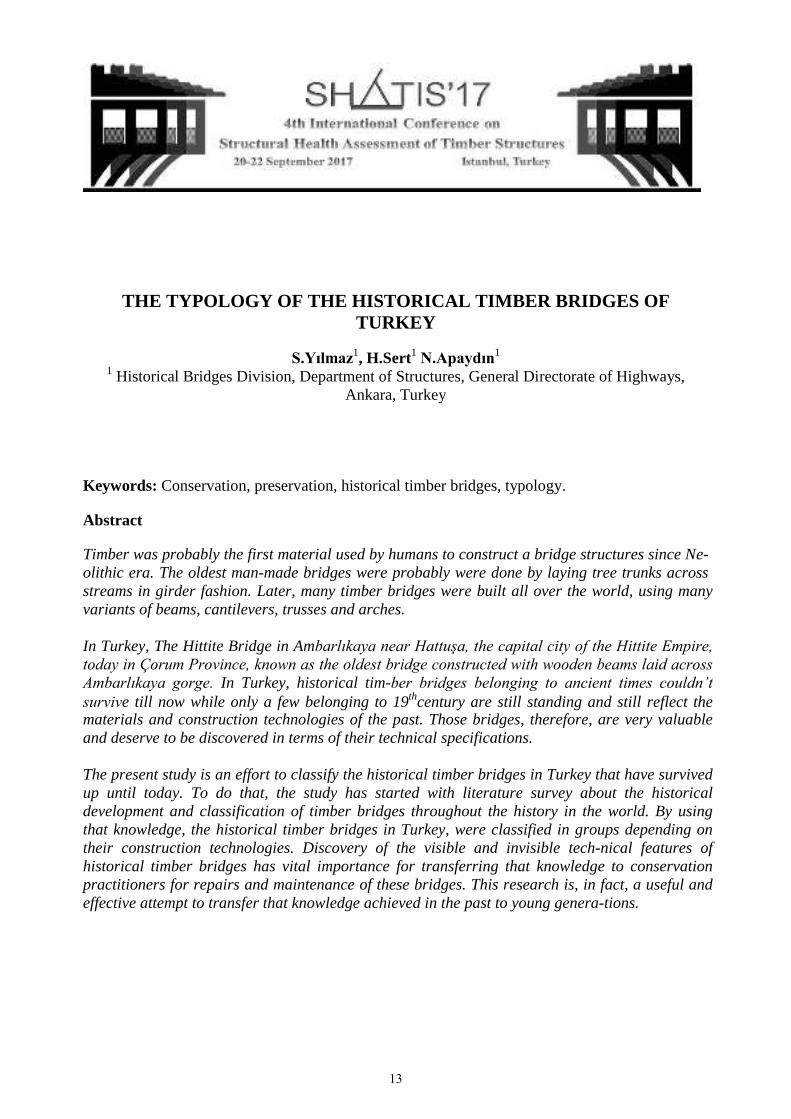
In ancient times, floating boats with intermediate piers were used as bridges to transit from one side to the another. Darius Bridge over the Bosphorus was constructed in 6th century B.C., where 674 boats crossed an obstacle of about 1500 meters [5]. Later, the Romans built timber beam bridges to ease transport; in particular, one of those bridges, known as Caesar’s Bridge (55 BC), is well documented by the Italian architect An-drea Palladio (1508–1580) (Malo, 2016). The bridge was built with simple, ready-made units and was easy to erect and then to dismantle after the passage of the army. At 5 to 6 meters wide, it was built in only 10 days, near Neuwied, where the width of the river was 140 meters (Setra 2006), (Figure 1). In 16th century, Andrea Palladio, the great architect of the renaissance, constructed timber beam bridge across the Brenta River in Bassano del Grappa (Italy) and it is described in a ta-ble of his treatise “The Four Books of Architecture”. The structure was repaired many times because of river floods and damages caused by war, but the one that is admired today is es-sentially the same bridge designed by the famous architect. The structure is a 5 span truss bridge, made entirely with wooden framework [3]. (Figure 2).
Figure 1: Caesar’s Bridge [5]. Figure 2: Palladio’s Bridge [5].
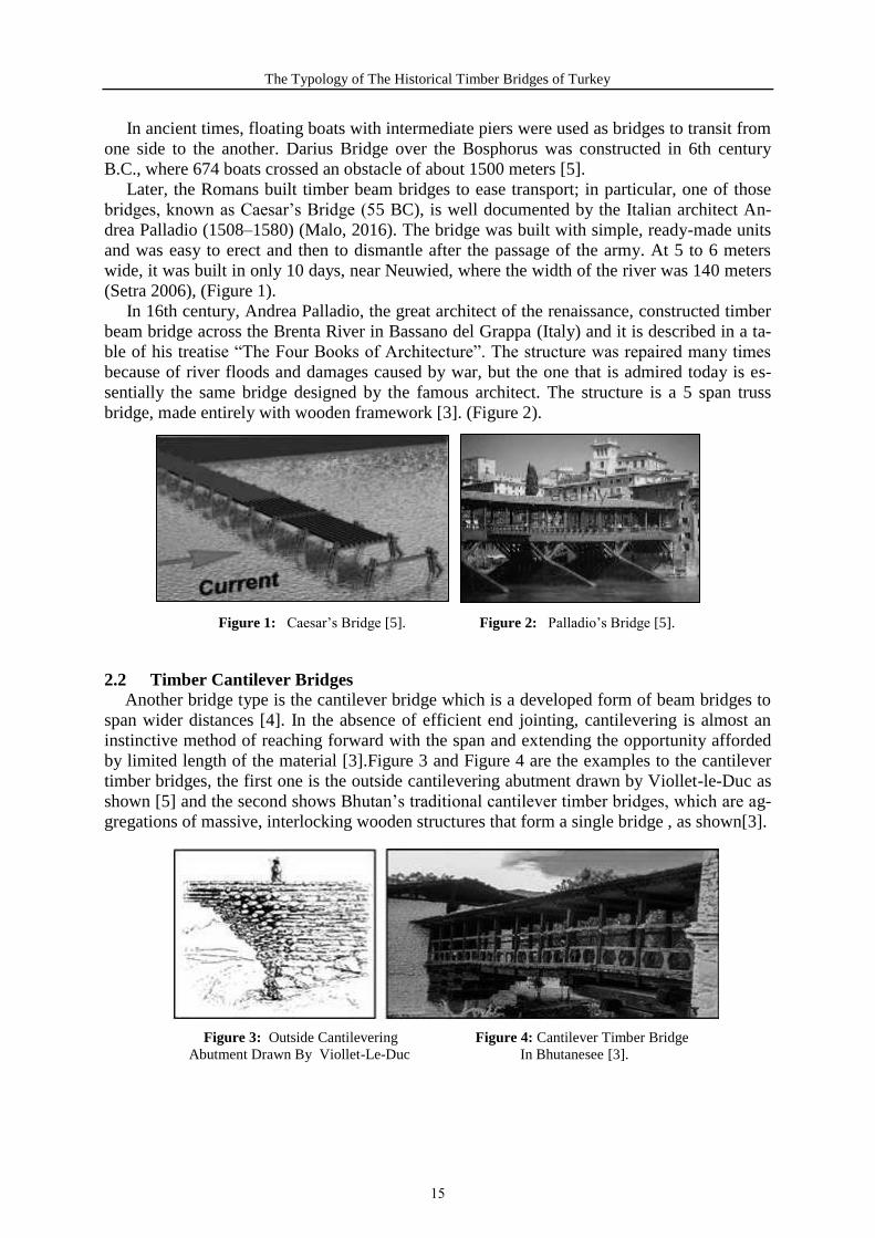
2.2 Timber Cantilever Bridges Another bridge type is the cantilever bridge which is a developed form of beam bridges to
span wider distances [4]. In the absence of efficient end jointing, cantilevering is almost an instinctive method of reaching forward with the span and extending the opportunity afforded by limited length of the material [3].Figure 3 and Figure 4 are the examples to the cantilever timber bridges, the first one is the outside cantilevering abutment drawn by Viollet-le-Duc as shown [5] and the second shows Bhutan’s traditional cantilever timber bridges, which are ag-gregations of massive, interlocking wooden structures that form a single bridge , as shown[3].
Figure 3: Outside Cantilevering Figure 4: Cantilever Timber Bridge Abutment Drawn By Viollet-Le-Duc In Bhutanesee [3].
15

S.Yılmaz, H.Sert, N.Apaydın
2.3 Timber Suspension BridgesSuspension timber bridges also date back to the early times. Basically, a suspension bridge
is formed with a rope hanging between the supports [4].For the last two century the suspen-sion bridge design has showed a great progress thanks to the developments in material science and construction technology.
Ideas for prototype suspension bridges probably came from hanging vines or stems. In subtropical parts of the world, palms with lengthy stems were used for constructing suspen-sion bridges [6].(Figure 5)
Figure 5: Early Highway Type Of Rope Bridge. This Example İs From The İsland Of Javaand Has An Apparent Span Of Approximately 100 Feet (Photo Courtesy Of
The American Society Of Civil Engineers: © 1976) [6].
According to the M. Goykoviç, before the Mostar arched stone bridge was constructed, there had been the wooden suspended bridge with span of 35 meter and it was at the altitude of 53.20 m above the sea level, and above the high water level (50.70 above the sea level on this place). His hypothetical reconstruction drawing of the pre-Ottoman bridge in Mostar is shown in Figure 6 [7].
While the reconstruction of Ottoman Mostar Bridge between 2002-2004, during the exca-vation works, holes for the placement of timber beam elements and iron nails were found in the bridge site, which verified hypothesis of Goykoviç [8] (Figure 7).
Figure 6: Hypotetical Reconstruction of the Figure 7: Archeological Investigation Pre-Ottoman Bridge in Mostar [7]. Proved Historical Development of The
Bridge Site [8].
2.4 Timber Arch BridgesThe first examples of arch bridges were built with stone, which has high compressive
strength so works well in compression. In time examples were built also with wood, brick,
16

The Typology of The Historical Timber Bridges of Turkey
iron, steel, and prestressed concrete [9].Building arch bridges was the practical way for span-ning large distances for many years. During the Roman Period, for the Emperor Trajan, multi arched timber Trajan Bridge was constructed with approx. 1200 m long. Leading to the modern day, Serbian River banks, for more than 1000 years this was the longest arch bridge ever constructed. It carried the Via Flamina, a road that began in Northern Italy and passed the shores of the Adriatic, crossing the Alps. Trajan bridge was depicted on Trajan Column [3].(Figure 8,9)
Figure 8: Reconstruction Drawing Figure 9: Trajan Column of Trajan Bridge and Timber Arch Bridge Depicted On It
China has a lot of wooden arch bridges that were with unique construction techniques and skills. The use of techniques of beams, tenons and mortises make wooden arch bridges in Fu-jian Province and Zhejiang Province distinctive and commendable called as rainbow and wo-ven bridges which were constructed by weaving straight logs crisscross together ( Figure 10, 11).
Figure 10, Figure 11: Chinese Timber Arch Bridge(Rainbow, Woven Bridge)
2.5 Timber Truss Bridges In the 16 century, Italian architect Palladio described the truss bridge in his I Quattro Libri
dell’ Architettura. Truss is the structural type which consists of triangles formed with the connected straight members. The straight members are subjected to both tension and com-pression forces and these forces are balanced in a truss. There are various types of trusses however they all have the advantage of the strength and a rigidity of a triangle [10],[4]. The first examples of truss bridges were constructed with wood. With the industrial revolution, the iron and steel replaced the wood in 19th century [10]. Palladio’s trussed footbridges which are statically determinate shows his ideas were re-markably advanced for the time 1579, recognizing the importance of achieving clear spans and using iron straps and bolts (Figure 12)
17

S.Yılmaz, H.Sert, N.Apaydın
Figure 12: Palladio’s truss bridge (From Four Books of Andrea Palladio’s Architecture,1736)
3 STRUCTURAL CLASSIFICATION OF TIMBER BRIDGES IN TURKEY
Traditionally timber was used in bridge construction, however stone is stronger and as a result able to better withstand natural conditions. Therefore, very few bridges dating back to 150 years ago as a maximum have survived to date [1].
Although it is a well known case that there exist 35 each bridges constructed generally by the local communities in Black Sea Region, the photographs for only 25 each of such bridges have been found out while it has been as curtained that 15 each of the same have survived to the present time [1]. The most superior properties of timber against stone are its lightness and tensile and flexural strength. Such features of timber allowed construction of overflow struc-tures and safer passageway for the larger spanning[3].
The timber bridges located in our country are mostly built on masonry piers and settled on the blocks supported by the main girder forming part of the massive flat system by overlap-ping the longitudinal and transverse beams on each other. The timber materials are used on the floor coverings, pillars and parapets while some of the bridges are covered by roofs. The trees such as pine, oak and chestnut have commonly been used in the construction of the bridges and the timber materials have been connected through clearance method using iron nails. In Turkey, timber bridges survived today were constructed in:
Beam,Cantilever,Suspension andHybrid forms.
3.1 Timber Beam BridgesThe first and earliest examples of timber bridges were constructed with fallen tree trucks
across a river which can be simply defined as a horizontal beam supported at each ends. In Turkey, The Hittite Bridge in Ambarlıkaya near Hattuşa, the capital city of the Hittite
Empire, today in Çorum Province, known as the oldest bridge constructed with wooden
18

The Typology of The Historical Timber Bridges of Turkey
beams laid across Ambarlıkaya gorge as Rudolf Naumann suggested. Inside the gorge there are many cupules or holes in the wall possibly to place the beam construction to hold a wood-en platform or a footway [11]. According to the Nauman, the bridge was constructed to pass 8.50 m span of the yard by stones on to the cavernous rocks in the form of stairs while the paved superstructure is passed through timber beams [11]. (Figure 13).
Figure 13: Reconstruction Drawing of Hittite Timber Bridge [11].
Second example from Turkey is Pulur which is also known as Yavuz Sultan Selim Bridge in Figure 14,15. It is located in Erzurum, Pulur Province, on Pulur River. It was constructed 15th century during the Ottoman Period with 135.35 m lenght and 5.50 m. width with four spans. While its piers were constructed with stone, the superstructure were passed by timber beam structure over it covered by soil covering. Bridge was restored by General Directorate of Highways between 2010-2012 [12].
Figure 14, Figure 15: Historical Pulur Bridge in Erzurum [12]
The third example of a timber beam bridge is Historical Yakaören Bridge in Abana Dis-trict in Kastamonu from late of 19th century. It is 18.50 m length and 2.80 m in width with one span of 11.52 m. It passes the river with two wooden logs with a 40 cm radius assembled over the stone abutments. The timber beam structure was supported under and over by strut-ting timber elements shown in Figure 16and 17. [13].
19

S.Yılmaz, H.Sert, N.Apaydın
Figure 16, Figure 17: Historical Yakaören Bridge in Kastamonu(Photographs taken by S.Yılmaz, June 2016)
3.2 Timber Cantilever Bridges A cantilever bridge is a developed form of beam bridges to span wider distances [4]. In
Turkey, timber bridges constructed with cantilevered beams are generally in hybrid forms be-cause of the additional construction forms. Here only cantilever timber bridge examples will be given from Turkey.
Historical Buzlupinar Bridge on Madenli Stream in Buzlupınar Village, in Çayeli district of Rize province. The bridge was burned out during a fire in 1906 and reconstructed by the inhabitants after the fire. The bridge is approximately 35 m in length and 2.20 m in width and its 21. 80 m span length decreased to 12.50 m by cantilever transverse and longitudinal beams overlapping to each other. Because the superstructure of the bridge was fallen down in1980s, it was restored by General Directorate of Highways between 2012-2016 [14],[10] (Figure 18,19).
Figure 18, Figure 19: Historical Buzlupınar Bridge in Rize [10].
3.3 Timber Suspension Bridges Basically, a suspension bridge is formed with a rope hanging between the supports [4]. In
Turkey, there are examples of timber suspension bridges hanged by structural timber ele-ments.
Historical Dörtocak Köprüsü is from 19th century in Tosya District in Kastamonu with 11.20m length and 3.90m width. One bridge was constructed over the river spanning 10 m with five wooden beams with a radius of 35 cm assembled on side Stone abutments. The su-perstructure of the bridge constructed with timber beam logs were hanged by timber elements. On the deck, trail woods were placed along the bridge deck for the easy access of coaches [15] (Figure 20,21).
20

The Typology of The Historical Timber Bridges of Turkey
Figure 20, Figure 21: Historical Dörtocak Bridge in Kastamonu (Photographs taken by S.Yılmaz, June 2016)
3.4 Timber Hybrid Bridges In Turkey, hybrid forms were generally used with the combination of cantilever and sus-
pension bridges. The first example is Historical Bayramören Bridge, located on Melan (Soğanlı) Stream in Bayramören Sub-District in Çankırı District, was built in order to provide access between vineyards and truck gardens on the other bank of the stream and the settlement area. It has been rumored that the bridge dates back to 150 years ago. The bridge is approximately 64.80 m in lenght and 4.00 m in width with double spanned of 12.21m and 17.03m.
The bridge has constructed with hybrid system which combines cantilever and suspension structural systems together. That is, the main timber girders were supported by the cantilever system established through overlapping and locking transverse and longitudinal beams on the stone piers and also the main timber girders were hanged by suspension timber elements at the same time. (Figure 22).The bridge floors were formed on the main girders at a height of 9.00 m from the base level and trail woods were placed along the bridge floors. Bridge was recon-structed by General Directorate of Highways between 2000-2001. (Figure 23, Figure 24) [16].
Figure 22: Historical Bayramören Bridge in Çankırı (Before restoration) [16].
Figure 23,24: Historical Bayramören Bridge in Çankırı (After restoration)[16].
21

S.Yılmaz, H.Sert, N.Apaydın
The second example is Historical Başkotanı Bridge located in Kabadüz District in Ordu. Bridge was constructed in 19th century with approximately 30 m lenghth and 2m width with one span of 18 m. The bridge has constructed with hybrid system that the main timber girders were supported by the cantilever system established through overlapping and locking trans-verse and longitudinal beams and also the main timber girders were hanged by suspension timber elements at the same time (Figure 25), [17].
Figure 25: Historical Başkotanı Bridge in Ordu constructed with hybrid system[17]
4 CONCLUSION
In Anatolia, historical timber bridges belonging to ancient times couldn’t survive till now while only a few belonging to 19thcentury are still standing and still reflect the materials andconstruction technologies of the past. Those bridges, therefore, are very valuable and deserve to be discovered in terms of their technical specifications.
The present study is an effort to classify the historical timber bridges in Turkey that have survived up until today. Classification is the first step to study and understand each bridge, in order to record its preservation state as well as to document the morphology and typology of the existing bridges. By this way, the knowledge achieved in the past on timber bridge con-struction could be discovered for their repair and maintenance, therefore their long-term sur-vival. The data achieved by the study is expected to be a useful and effective attempt to transfer the knowledge achieved in the past to young generations.
REFERENCES
[1] General Directorate of Highways (GDH), Inventory of the Division of Historical Bridges, Ankara, Turkey, 2016
[2] Sert, H.et.al., Specifications, Legislation, Inventory, Projects and Maintenance – Repair of Historical Bridges, GDH Publication No: 268, GDH Printing House, Ankara, Turkey, 2009.
[3] Mettem, C. J., Timber Bridges. New York, NY: Spon Press, 2011.
[4] Brown, D. J., Bridges: Threee Thousand Years of Deyfing Nature, St. Paul, MN, USA: MBI Publishing Company. 2001.
[5] Setra, Technical Guide Timber Bridges How to Ensure Their Durability, Ministere de l’Ecologie du Development et de I’Amenagement Durables, 2006.[6] Ritter, Michael A., Timber Bridges: Design, Construction, Inspection, and Maintenance, Washington, DC: 944 p, 1990.
22
The Typology of The Historical Timber Bridges of Turkey
[7] Pašić, A., The Old Bridge (Stari most) in Mostar, Research Centrefor Islamic History, Art, and Culture. Istanbul, 1995.
[8] Sert, H., Mostar Köprüsü, Icanas 38.İnternational Congress Of Asian And North African Studies,, Atatürk Supreme Council Of Culture, Language And History, Ankara,Turkey, 2007.
[9] Denison, E., & Stewart, I., How To Read Bridges: A Crash Course In Engineering And Architecture. New York, Ny 10010: Rizzoli, 2012.
[10] Çabuk, E., Structural Modelling, Analysis And Evaluation Of The Historic Buzlupinar Bridge And Recommendations For Its Reconstruction, Master Thesis, Metu, Ankara, Turkey, 2015.
[11] Nauman ,R., Eski Anadolu Mimarliği, Turkish Historical Society, Ankara,Turkey 2007. [12] General Directorate Of Highways (Gdh), Historical Pulur Bridge Restoration Projects And Technical Report, Gdh Archieve, Archieve Registration No:.12/İ.25/N.86/ Rup-2012, Ankara, Turkey, 2012.
[13] General Directorate Of Highways (Gdh), Historical Yakaören Bridge Restoration Pro-jects And Technical Report, Gdh Archieve, Archieve Registration No:. B.15/İ.37/N.86/ Rup-2015, Ankara, Turkey, 2015.
[14] General Directorate Of Highways (Gdh), Historical Buzlupinar Bridge Restoration Pro-jects And Technical Report, Gdh Archieve, Archieve Registration No:. : B.10/İ.53/N.86/ Rup-2012, Ankara, Turkey, 2012.
[15] General Directorate Of Highways (Gdh), Historical Dörtocak Bridge Restoration Pro-jects And Technical Report, Gdh Archieve, Archieve Registration No:. : B.15/İ.37/N.85/ Rup-2015, Ankara, Turkey, 2015.
[16] General Directorate Of Highways (Gdh), Historical Bayramören Bridge Restoration Projects And Technical Report, Gdh Archieve, Archieve Registration No:B.15/İ.37/N.85/ Rup-2015, Ankara, Turkey, 2015.
[17] General Directorate Of Highways (Gdh), Historical Başkotani Bridge Restoration Pro-jects And Technical Report, Gdh Archieve, Archieve Registration No: B.10/İ.55/N.25/ Rup-2016, Ankara, Turkey, 2016.
23

24

THE EXPANSION OF MANSARD ROOFS ACROSS EUROPE IN 18TH CENTURY
Ałykow K.1, Napiórkowska-Ałykow M.1 1 Team of Civil Engineers AŁYKOW, Lubań/ Poland
Keywords: Church, Rafter Framing, Roof Framing Expansion, Baroque, Mansard Roof
Abstract
The expansion of wooden roof structures in Europe has been discussed many times before. Also, some at-tempts have been made to classify rafter framing according to special features of their structural frame-work, not only with reference to the development of their design techniques, but also, for example, from the dendrological standpoint [1]..
The size of wooden roof structures was subject to considerable changes over the centuries, beginning from the largest in the 13th century, and then gradually decreasing by the 18th century.
Yet, apart from the technical knowledge in its strict sense, the shape of the Baroque churches and cathe-drals, and accordingly the form of their wood structural framing was also influenced by both the political situation of the time and the circumstances resulting from certain religious doctrines. The appearance of wooden barrels in the Baroque era which feigned vaulting, and made it possible to cover extensive spaces, had a significant impact on the change of the structural framework.
In this article, the authors present the trends in the expansion of shape and form of rafter framing used in the hall churches across Central Europe in the 18th century. The authors attempt to analyze the trends in the development of carpentry techniques for the timber-framed Mansard roofs in the Baroque era, used in sacred architecture across Europe, resulting from the political circumstances of which the direct influence on the development of carpentry techniques was reflected in the implemented building technologies.
25

Ałykow K., Napiórkowska-Ałykow M.
1 INTRODUCTION
The development of roof structures began in Northern France and Belgium in the 12th cen-tury and was very dynamic in the 13th as well as between 15th and 17th centuries. In the 14th and 18th centuries a significant decline in that development could be noticed. The size of tim-ber roof structures were subject to substantial changes over the centuries, beginning from the most significant ones in the 13th century and gradually decreasing all the way up to the 18th century. In literature [2] of the 18th century there were only two mentions of rafter framings which were significant from the standpoint of the development of these types of structures.
The first one was the stretcher construction with lying trusses (“liegender Stuhl”) enabling the insertion of the vault into the roof framework.
2 THE DEVELOPMENT OF RAFTER FRAMING IN EUROPE
The development of roof framing which led to the creation of a pitched roof with various roof angles (roof structures with a pitch of the same angle had already been known in Poland, for instance, as the “Cracow’s Roof”) may be observed as illustrated by the examples present-ed below (Fig. 1) [2].
Figure 1: An example of the development of timber roof structures in Northern France and Belgium [1]
The structures designed in France in the 17th century by an architect François Mansart, named after his name as mansard roof, which were used in France predominantly in distinc-tive buildings and mansions, gained huge popularity in German speaking countries [3] and were dominant structures throughout the 18th century until the Louis XIV’s Classicism style came into being, when gable single-panel roofs were back in fashion. What is characteristic is that in the French sacred buildings gable roofs were still predominant structures whereas the mansard roof used for building sanctuaries, due to the Huguenot carpenters who had settled in the region of Hesse and Prussia, was described as the “Huguenot style” (Fig. 2).
Despite the fact that the timber roof structures, which evolved in the Baroque period to take the form of a mansard roof, are in principle analogous throughout Europe, when analyz-ing the described structures situated south and west of Silesia [4, 5], one may arrive at the conclusion that at least with reference to this analysis, the most crucial are those studies which refer to the description of the development of timber roof structures in German-speaking terri-tories [6, 7].
What is interesting is that the farther east we go, the more mansard structures we can find, whereas west of France these types of structures did not gain such recognition. Similarly, the bordering region for the existence of these types of structures is the Silesia Region, while east of Silesia these structures are rare in secular buildings and they are not present in religious buildings at all [8, 9].
26
The expansion of mansard roofs across Europe in 18th century
Figure 2: The development of rafter framing in Europe
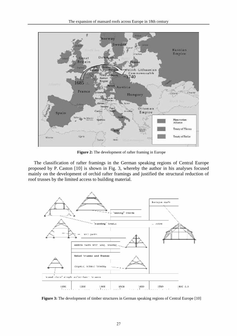
The classification of rafter framings in the German speaking regions of Central Europe proposed by P. Caston [10] is shown in Fig. 3, whereby the author in his analyses focused mainly on the development of orchid rafter framings and justified the structural reduction of roof trusses by the limited access to building material.
Figure 3: The development of timber structures in German speaking regions of Central Europe [10]
1685~1740
27

Ałykow K., Napiórkowska-Ałykow M.
Timber roof structures found in the territories of German speaking Central Europe have been described a number of times in German literature, beginning as early as in the 17th cen-tury [11], with a great number of publications appearing particularly at the turn of the 19th and 20th centuries[12], which was the effect of a rapid development of engineering sciences that originated in the 19th century and reached its peak at the turn of the 20th century.
It has to be recognized, though, that it was only in German-speaking countries that the mansard structures where in the roof trusses the truss beam was replaced with its residual form – the rafter [13] – are so common. Such significant interference with the static arrange-ment of the structure forced the builders of those times to additionally enforce the structure around the mansard by using the additional, earlier redundant, structural elements in the form of lying trusses and various types of struts allowing for the proper distribution of stresses [14]. Rafter framings used since the Middle Ages had remained a relic of the sacred buildings structure but they were still used in the 19th century in churches with half-timbered walls[15]. When analyzing the structure of the main coupes in rafter framing of naves with very broad span, one can also notice their similarity to the wooden structures of bridge spans [16]. This is especially visible within the rafter-lying truss-tie beam structural elements, which is even more visible when this type of static arrangement is additionally stiffened with struts. It is not without significance here that this particular period marks the beginning of the development of technical sciences, which soon after – at the time of the industrial revolution – assumed its systematized forms, that could be noticed particularly at the military technical academies of Paris and Berlin, where the main focus was given to the advancement of bridge construction technologies and the development of their scientific principles.
3 THE DEVELOPMENT OF TIMBER ROOF STRUCTURE IN POLAND
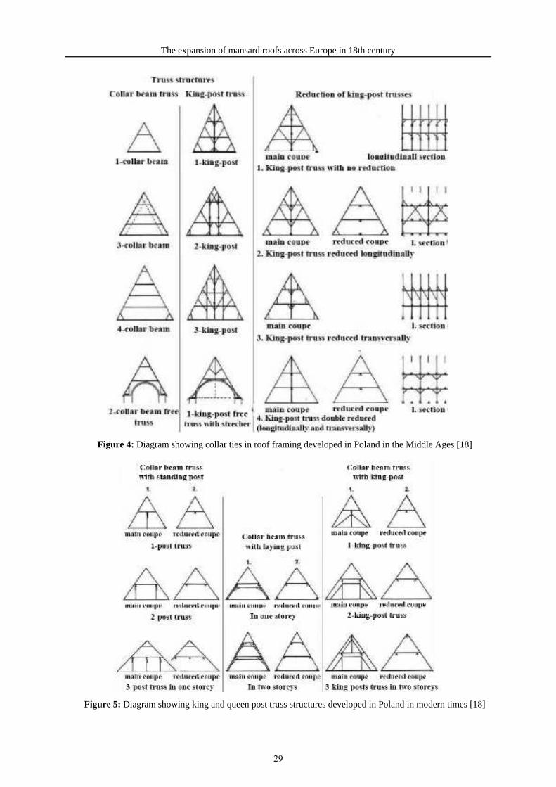
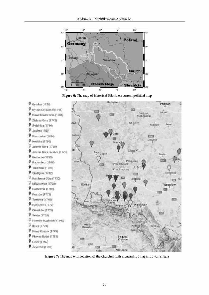
In those regions which constituted Poland [17] some timber roof structures dating from 14th century onwards have been preserved, however, when they were erected in the 18th cen-tury their number did not decline which was so characteristic of the areas of Northern France and Belgium; it was quite the opposite, the 18th century dominance of orchid rafter framings (Fig. 4) [18] ended and was replaced by stretcher construction with lying trusses (Fig. 5) [18].
4 THE GEOGRAPHIC RANGE OF 18TH-CENTURY MANSARD STRUCTURES IN POLAND
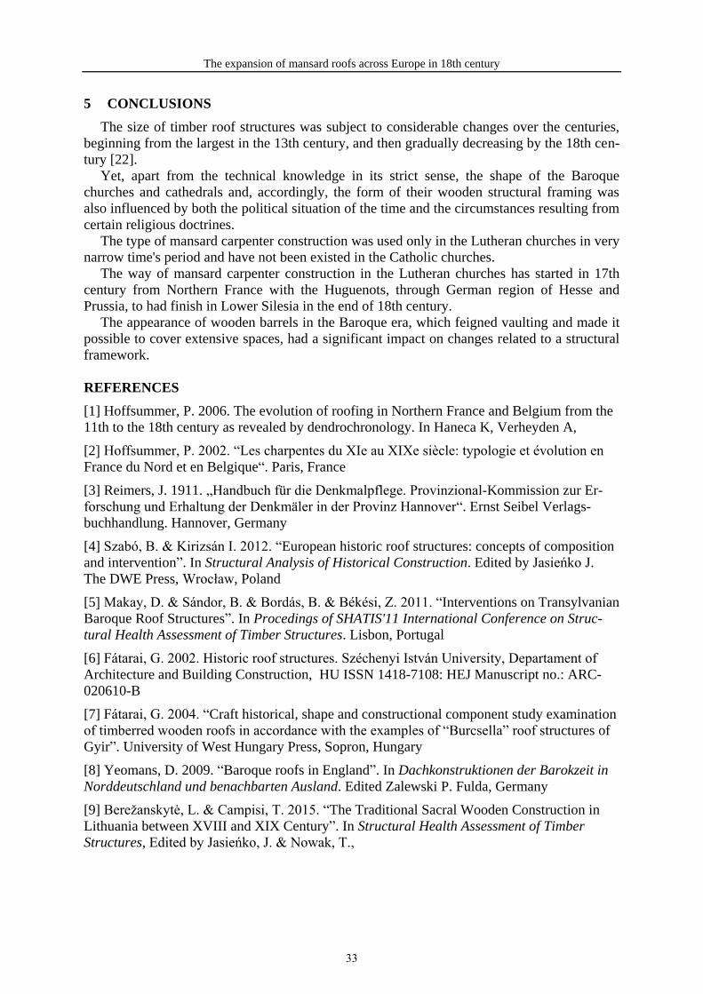
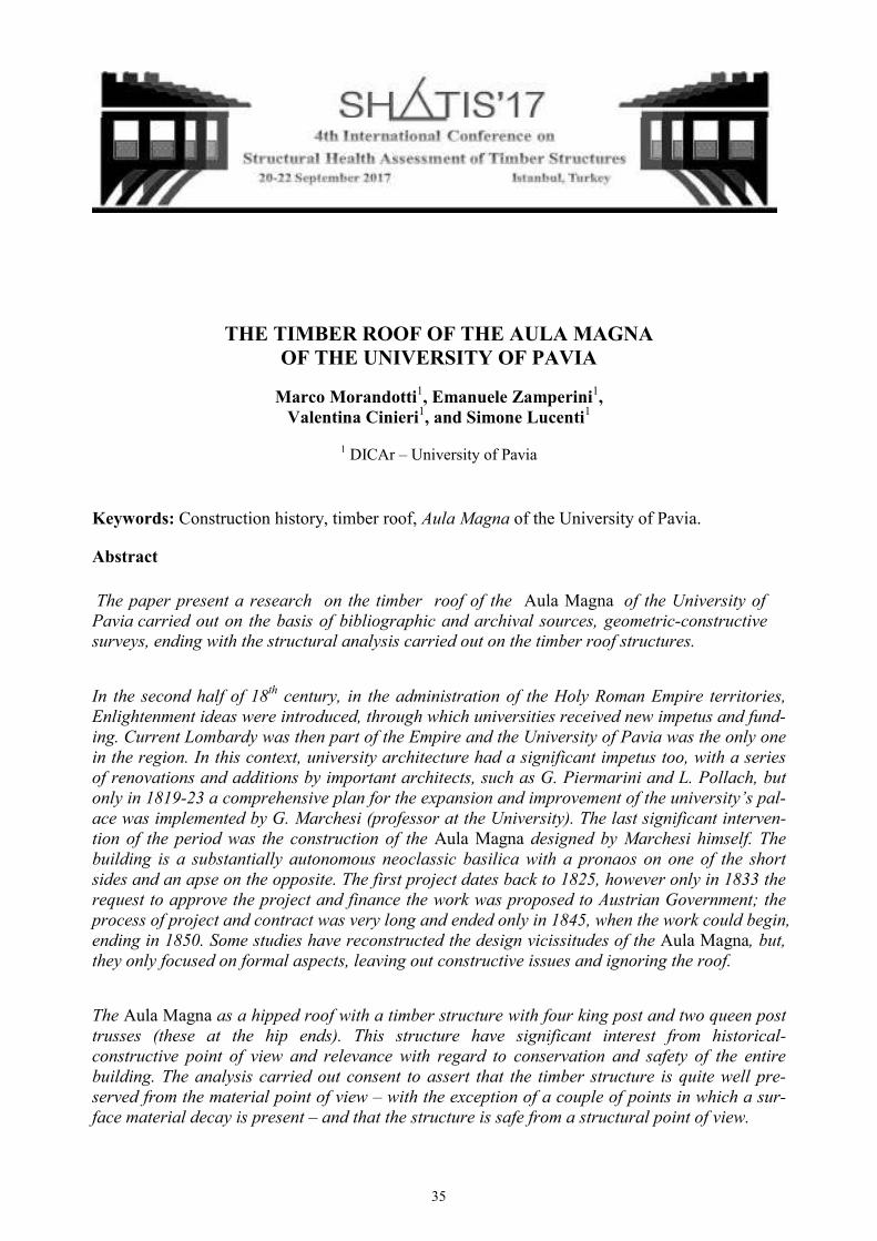
Based on the analysis of the development of construction characteristic for those times it is possible to observe gradual expansion of mansard structures across the area of current Lower Silesia region (Fig. 6). The map shown below depicts the location pattern of the churches with a mansard roofing (Fig. 7.) As we can observe it’s the areas of Lower Silesia region, which were mostly under the strongest influence of mansard construction style characteristic for 17th and 18th centuries.
28
The expansion of mansard roofs across Europe in 18th century
Figure 4: Diagram showing collar ties in roof framing developed in Poland in the Middle Ages [18]
Figure 5: Diagram showing king and queen post truss structures developed in Poland in modern times [18]
29
Ałykow K., Napiórkowska-Ałykow M.
Figure 6: The map of historical Silesia on current political map
Figure 7: The map with location of the churches with mansard roofing in Lower Silesia
30

The expansion of mansard roofs across Europe in 18th century
Figure 8: The map with location of the churches with mansard roofing
The authors have analyzed some churches, which are located in Lower Silesia region and have been erected in 18th centuries (Fig. 8). The main information about the construction of roofing are shown in the Table 1.
Table 1: The main information about construction of roofing.
Num
ber
Loca
tion
of th
e ch
urch
Yea
r of
ere
ctio
n R
afte
r ce
nter
s [m
] T
he s
pan L
of
rafte
r fr
amin
g [m
]
The
hei
ght H
of
rafte
r fr
amin
g [m
]
The
woo
d co
n-su
mpt
ion
by 1
m²
of r
oof s
lope
[m
³]
L
1 Iłowa 1729 1.15 17.65 12.35 0.098 2 Nowy Kościół 1749 1.34 17.15 9.00 0.097 3 Kosiska 1750 0.80 14.85 8.10 0.108 4 Cieplice 1779 1.15 23.58 13.60 0.140 5 Pławna Dolna 1781 1.50 19.00 12.35 0.161 6 Siedlęcin 1782 1.27 16.15 11.60 0.139 7 Ocice 1782 1.20 17.60 9.41 0.119 8 Żeliszów 1797 1.54 19.00 11.93 0.206
Figure 9. and 10. presents the trends in the expansion of shape and form of rafter framing used in the hall churches, which have been analyzed by the authors [19, 20, 21].
1) Iłowa (1729) 2) Nowy Kościół (1749) 3) Kosiska (1750) 4) Cieplice (1779)
H
1
2
3
4
5
6
7
8
1
8 2
6 7
5
3
4
31

Ałykow K., Napiórkowska-Ałykow M.
5) Pławna Dolna (1781) 6) Siedlęcin (1782) 7) Ocice (1782) 8)Żeliszów (1797)
Figure 9: The trends in the expansion of shape and form of rafter framing [19, 20, 21]
a) b)
c) d)
e) f)
g) h)
Figure 10: Selected churches from the Table 1. a) Iłowa, b) Nowy Kościół c) Kosiska, d) Cieplice, e)Pławna Dolna, f) Siedlęcin, g) Ocice, h) Żeliszów
32
The expansion of mansard roofs across Europe in 18th century
5 CONCLUSIONS
The size of timber roof structures was subject to considerable changes over the centuries, beginning from the largest in the 13th century, and then gradually decreasing by the 18th cen-tury [22].
Yet, apart from the technical knowledge in its strict sense, the shape of the Baroque churches and cathedrals and, accordingly, the form of their wooden structural framing was also influenced by both the political situation of the time and the circumstances resulting from certain religious doctrines.
The type of mansard carpenter construction was used only in the Lutheran churches in very narrow time's period and have not been existed in the Catholic churches.
The way of mansard carpenter construction in the Lutheran churches has started in 17th century from Northern France with the Huguenots, through German region of Hesse and Prussia, to had finish in Lower Silesia in the end of 18th century.
The appearance of wooden barrels in the Baroque era, which feigned vaulting and made it possible to cover extensive spaces, had a significant impact on changes related to a structural framework.
REFERENCES
[1] Hoffsummer, P. 2006. The evolution of roofing in Northern France and Belgium from the 11th to the 18th century as revealed by dendrochronology. In Haneca K, Verheyden A,
[2] Hoffsummer, P. 2002. “Les charpentes du XIe au XIXe siècle: typologie et évolution en France du Nord et en Belgique“. Paris, France
[3] Reimers, J. 1911. „Handbuch für die Denkmalpflege. Provinzional-Kommission zur Er-forschung und Erhaltung der Denkmäler in der Provinz Hannover“. Ernst Seibel Verlags-buchhandlung. Hannover, Germany
[4] Szabó, B. & Kirizsán I. 2012. “European historic roof structures: concepts of composition and intervention”. In Structural Analysis of Historical Construction. Edited by Jasieńko J. The DWE Press, Wrocław, Poland
[5] Makay, D. & Sándor, B. & Bordás, B. & Békési, Z. 2011. “Interventions on Transylvanian Baroque Roof Structures”. In Procedings of SHATIS'11 International Conference on Struc-tural Health Assessment of Timber Structures. Lisbon, Portugal
[6] Fátarai, G. 2002. Historic roof structures. Széchenyi István University, Departament of Architecture and Building Construction, HU ISSN 1418-7108: HEJ Manuscript no.: ARC-020610-B
[7] Fátarai, G. 2004. “Craft historical, shape and constructional component study examination of timberred wooden roofs in accordance with the examples of “Burcsella” roof structures of Gyir”. University of West Hungary Press, Sopron, Hungary
[8] Yeomans, D. 2009. “Baroque roofs in England”. In Dachkonstruktionen der Barokzeit in Norddeutschland und benachbarten Ausland. Edited Zalewski P. Fulda, Germany
[9] Berežanskytė, L. & Campisi, T. 2015. “The Traditional Sacral Wooden Construction in Lithuania between XVIII and XIX Century”. In Structural Health Assessment of Timber Structures, Edited by Jasieńko, J. & Nowak, T.,
33

Ałykow K., Napiórkowska-Ałykow M.
[10] Caston, P. 2006. “Historic Roof Trusses between 1500 and 1700 in German-speaking Central Europe: Documentation, Analysis and Development”. In Procedings of the Second International Congress on Construction History. Queens’ College Press, Cambridge, UK
[11] Wilhelm, J. 1868. „Architectura Civilis“. Paul Fuerstens Verlag, Nuremberg, Germany
[12] Schmidt, E. & Landsberg, T. 1897. „Dachstuhl-Konstruktionen und Dächer“. Stuttgart, Germany
[13] Köck, B. & Holzer S. M. 2009. „Baroque Timber Roofs without a Continuous Tiebeam”. In Proceedings of the Third International Congress on Construction History. Cottbus, Ger-many
[14] Köck, B. 2011. “Barocke Dachwerke: Konstruktion und Tragverhalten”. Institut für Mathematik und Bauinformatik Universität der Bundeswehr München. Neubiberg, Germany
[15] Langewiesche, K. R. 1983. „Fachwerkkirchen in Hessen“. Marburg, Germany
[16] Gadola, R. 2009. „Tragwerk und Raumform in Grubenmanns Kirchen”. TEC21 42-43
[17] Ganowicz, R. 2000. „Historyczne więźby dachowe polskich kościołów – Historyczny rozwój ciesielskich konstrukcji dachowych w polskich kościołach”. Poznań, Poland
[18] Tajchman, J. 2005. „Propozycja systematyki i uporządkowania terminologii ciesielskich konstrukcji dachowych występujących na terenie Polski od XIV do XX w”. In Monument Edited by Morysiński T., Warszawa, Poland
[19] Ałykow K. & Napiórkowska-Ałykow M. 2012. „The influence of the 19th century tech-nical solution of the work oof the Baroque hall churches”. In Structural Analysis of Historical Constructions, Edited by Jasieńko.
[20] Ałykow K. & Napiórkowska-Ałykow M. 2013. „The influence of faulty 19th century technical solution on work of 18th century rafter framing as exemplified by church in Nowy Kościół in Lower-Silesia, Poland - case study”. In Advanced Materials Research, Trans Tech Publications 778(2013) Pp: 903-910.
[21] Ałykow K. & Napiórkowska-Ałykow M. 2015. „First the roof than the walls. Influence of the political situation on the building technology”. In Structural Health Assessment of Tim-ber Structures. Edited by Jasieńko, J. & Nowak, T. [22] Chrzanowski, T., Piwocki, K. 1981. „Drewno w polskiej architekturze i rzeźbie ludowej”. Warszawa, Poland
34
1 1
1 1
1 DICAr – University of Pavia
Construction history, timber roof, of the University of Pavia.
Aula Magna
Aula Magna
Aula Magna
Aula Magna
35
Marco Morandotti, Emanuele Zamperini, Valentina Cinieri and Simone Lucenti
The paper present a research on the timber roof of the of the University of Pavia – a part of the central University Palace – built between 1845-50. The study has been carried out on the basis of bibliographic and archival researches and on direct geometric and constructive surveys.
Archival research was conducted at Pavia State Archive and in the historical archives of the University of Pavia. Surveys have been done by the students of the course
(academic year 2015-16) held by professor Marco Morandotti, with the collaboration of Emanuele Zamperini, Valentina Cinieri and Simone Lucenti.
The students’ research also involved the structural analysis of the timber roof structures carried out under the supervision of Emanuele Zamperini.
On the basis of a tradition of high level studies dating back to late antiquity, the University of Pavia was instituted in 1361 when Galeazzo II Visconti – imperial vicar – obtained by Em-peror Charles IV the constitution of a in Pavia.
For more than a century, The university had no specific building for teaching, and profes-sor lectured in suitable rooms found in convents, purposely rented private houses and in the Town Hall [1]. The University had for the first time its own building between 1485 and 1490, when Ludovico il Moro granted it in use a palace previously belonged to Azzone Visconti. The palace had two courtyards and was located adjacent to the San Matteo; it corresponds to the two northern courtyards. In 1534, in the two courtyards arcades on the ground floor and balconies on the upper floor were built; porches and balconies were renovated around 1670 by architect Ambrogio Pessina [2].
In the second half of 18th century, after Maria Theresa of Habsburg’s ascent to the throne of Austria and during the reign of Joseph II of Habsburg-Lorraine, in the administration of the Holy Roman Empire territories, Enlightenment ideas were introduced, through which univer-sities received new impetus and funding. Current Lombardy was then part of the Empire and the University of Pavia was the only one in the region. In this context of university renewal, architecture had a significant impetus too, with a series of renovations and small extensions designed by important architects, such as Giuseppe Piermarini and Leopoldo Pollach.
In 1771-73 architect Giuseppe Piermarini modified porches and balconies and designed an at the first floor, in the part of the palace dividing the two courtyards [3].
In the last two decades of the century, Joseph II deeply renewed theological studies and concentrated them in Pavia; therefore he promoted the construction of the third courtyard built demolishing part of the suppressed Monastery of Leano, which was located in the block im-mediately south of the University, from it separated by a street. The courtyard was finished in 1785 according to the design by Leopoldo Pollach. Pollach hoped that the University could annex the street, therefore he built porches and balconies only on three sides of the courtyard, planning to realize the fourth side instead of the street. Between 1785 and 1786 two big class-room were built by Pollach for anatomy and physics lessons, with a semicircular plan and tiered seating, having classical theatres as a model [2, 3].
After the Napoleonic period, Austrian restoration brought a new reorganization of studies, resulting in a significant increase in lessons, which required to quickly provide for the con-struction of new classrooms. Between 1819 and 1823 a comprehensive plan for the expansion and improvement of the university’s palace was implemented by Giuseppe Marchesi (profes-sor of Architecture at the University). New classrooms and offices for rector, faculties direc-
36
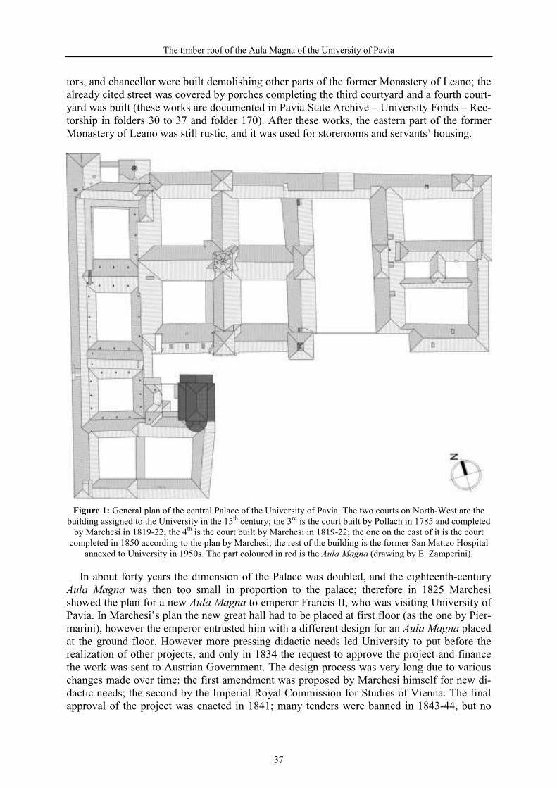
The timber roof of the Aula Magna of the University of Pavia
tors, and chancellor were built demolishing other parts of the former Monastery of Leano; the already cited street was covered by porches completing the third courtyard and a fourth court-yard was built (these works are documented in Pavia State Archive – University Fonds – Rec-torship in folders 30 to 37 and folder 170). After these works, the eastern part of the former Monastery of Leano was still rustic, and it was used for storerooms and servants’ housing.
General plan of the central Palace of the University of Pavia. The two courts on North-West are the building assigned to the University in the 15th century; the 3rd is the court built by Pollach in 1785 and completed
by Marchesi in 1819-22; the 4th is the court built by Marchesi in 1819-22; the one on the east of it is the court completed in 1850 according to the plan by Marchesi; the rest of the building is the former San Matteo Hospital
annexed to University in 1950s. The part coloured in red is the (drawing by E. Zamperini).
In about forty years the dimension of the Palace was doubled, and the eighteenth-century was then too small in proportion to the palace; therefore in 1825 Marchesi
showed the plan for a new to emperor Francis II, who was visiting University of Pavia. In Marchesi’s plan the new great hall had to be placed at first floor (as the one by Pier-marini), however the emperor entrusted him with a different design for an placed at the ground floor. However more pressing didactic needs led University to put before the realization of other projects, and only in 1834 the request to approve the project and finance the work was sent to Austrian Government. The design process was very long due to various changes made over time: the first amendment was proposed by Marchesi himself for new di-dactic needs; the second by the Imperial Royal Commission for Studies of Vienna. The final approval of the project was enacted in 1841; many tenders were banned in 1843-44, but no
37
Marco Morandotti, Emanuele Zamperini, Valentina Cinieri and Simone Lucenti
building contractor showed up because the base bid price was too low, since it was based on costs estimated several years before; only in 1845 the contract was awarded and the work could begin. Marchesi (then almost seventy) gave up the direction of the work, which was en-trusted to Giovanni Battista Vergani (professor of Drawing at the University), who directed them until their end in 1850, after a long break due to the revolutionary movements of 1848.
Evidence for these works are in many documents stored in Pavia State Archive (University Fonds – Rectorship – folder 170, file 1), a manuscript containing the technical report, the specifications and bill of quantities of works signed by Marchesi is stored in the Manuscript fonds of the University Library of Pavia ( ), instead none of the origi-nal drawing by Marchesi has been discovered in the archives consulted; an effective synthesis of historical events is present in [4].
Marchesi’s project completed the University Palace by placing the in the east-ernmost part of the former monastery of Leano, giving an end to the renovation of the rest of the complex. The building is a substantially autonomous neoclassic basilica with a pronaos on one of the short sides and an apse on the opposite.
Since then the works done on the Palace were partial renovations or superelevation only, and none of them significantly involved the or immediately adjacent spaces. Only in 1950s the Palace expanded again – more than doubling in dimension – with the an-nexation of the buildings of the former San Matteo Hospital.
From a geometric point of view we can describe the Great Hall as formed by five distinct volumes: the pronaos, the properly called hall, the apse, and the two lateral longitudinal body, parallel to the hall and corresponding to the internal balconies.
The pronaos has an autonomous gable roof; the apse has a semi truncated conical roof end-ing at the top with a skylight now covered with a single pitch with curved tiles; the lateral bodies are single pitched, in the back of the hall they are connected to the roof of the rest of the building, in the front they end with a hip; the roof above the properly called hall is a hipped roof. Since the other parts of the roof are not accessible and of minor constructive im-portance, the paper will focus on the hipped roof of the hall.
The Great Hall photographed from south-west. We can see the hipped roof of the hall and the roof of the apse shaped as a truncated cone with a single pitch covering the former skylight (photo by E. Zamperini).
38

The timber roof of the Aula Magna of the University of Pavia
In the manuscript – signed by architect Giuseppe Marchesi – containing the technical re-port, the specifications and bill of quantities (Manoscritto ticinese 354 stored at the University Library of Pavia) there is a detailed description of the designed roof structure of the hall, how-ever, the depicted roof has some substantial differences from the existing one; most likely these differences arise from changes decided in phase of construction.
The has a timber structure with four king post and two queen post trusses (these in the mid of the hipped ends); at each of the two extremities there are a couple of hip rafters, one “half principal” rafter going from the vertex of the roof (end of the ridge) to the middle of the eave and other two from the queen posts to the quarters of the eave (fig. 3).
The roof depicted in the technical report has five king post trusses (necessarily placed be-tween the two vertex of the roof), two hip rafters and a “half principal” rafter at each hip end, and two smaller rafters that depart from the mid of each hip rafter and go to the walls (fig. 4).
Scheme of the existing timber structure of the as it has been surveyed. We can see: four king post trusses (in red); two queen post trusses (in magenta); the hip rafters (in cyan); the rafters direct as
the maximum slope lines of the roof (in blue); the purlins (in green) (drawing by E. Zamperini).
Scheme of the timber structure of the as it is described in the technical report. We can see: five king post trusses (in red); the hip rafters (in cyan); the rafters direct as the maximum slope lines of the roof
(in blue); the purlins (in green) (drawing by E. Zamperini).
39
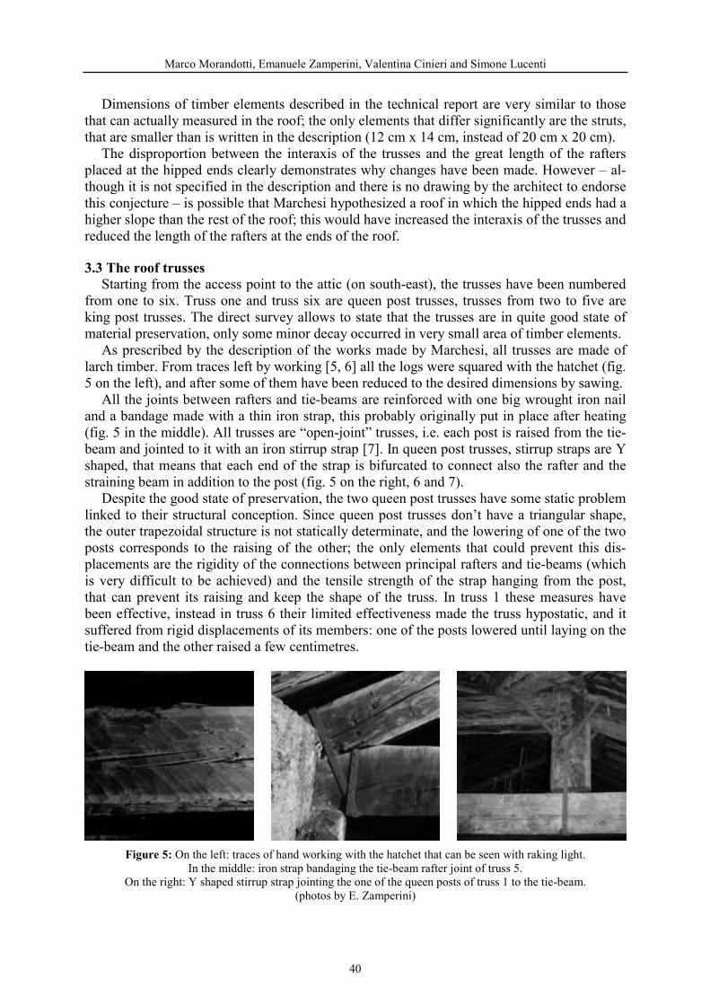
Marco Morandotti, Emanuele Zamperini, Valentina Cinieri and Simone Lucenti
Dimensions of timber elements described in the technical report are very similar to those that can actually measured in the roof; the only elements that differ significantly are the struts, that are smaller than is written in the description (12 cm x 14 cm, instead of 20 cm x 20 cm).
The disproportion between the interaxis of the trusses and the great length of the rafters placed at the hipped ends clearly demonstrates why changes have been made. However – al-though it is not specified in the description and there is no drawing by the architect to endorse this conjecture – is possible that Marchesi hypothesized a roof in which the hipped ends had a higher slope than the rest of the roof; this would have increased the interaxis of the trusses and reduced the length of the rafters at the ends of the roof.
Starting from the access point to the attic (on south-east), the trusses have been numbered from one to six. Truss one and truss six are queen post trusses, trusses from two to five are king post trusses. The direct survey allows to state that the trusses are in quite good state of material preservation, only some minor decay occurred in very small area of timber elements.
As prescribed by the description of the works made by Marchesi, all trusses are made of larch timber. From traces left by working [5, 6] all the logs were squared with the hatchet (fig. 5 on the left), and after some of them have been reduced to the desired dimensions by sawing.
All the joints between rafters and tie-beams are reinforced with one big wrought iron nail and a bandage made with a thin iron strap, this probably originally put in place after heating (fig. 5 in the middle). All trusses are “open-joint” trusses, i.e. each post is raised from the tie-beam and jointed to it with an iron stirrup strap [7]. In queen post trusses, stirrup straps are Y shaped, that means that each end of the strap is bifurcated to connect also the rafter and the straining beam in addition to the post (fig. 5 on the right, 6 and 7).
Despite the good state of preservation, the two queen post trusses have some static problem linked to their structural conception. Since queen post trusses don’t have a triangular shape, the outer trapezoidal structure is not statically determinate, and the lowering of one of the two posts corresponds to the raising of the other; the only elements that could prevent this dis-placements are the rigidity of the connections between principal rafters and tie-beams (which is very difficult to be achieved) and the tensile strength of the strap hanging from the post, that can prevent its raising and keep the shape of the truss. In truss 1 these measures have been effective, instead in truss 6 their limited effectiveness made the truss hypostatic, and it suffered from rigid displacements of its members: one of the posts lowered until laying on the tie-beam and the other raised a few centimetres.
On the left: traces of hand working with the hatchet that can be seen with raking light. In the middle: iron strap bandaging the tie-beam rafter joint of truss 5.
On the right: Y shaped stirrup strap jointing the one of the queen posts of truss 1 to the tie-beam. (photos by E. Zamperini)
40

The timber roof of the Aula Magna of the University of Pavia
Northern façade of truss 1 (drawing by S. Albertario, F. Lipari, M. Pasini, X. Qushku).
Southern façade of truss 6 (drawing by G. Bolognesi, M. Borreca, A. Chiesa, G. Ferri).
The four king post trusses are very similar to each other, however due to some differences in the materials used (localized defects of timber) and because of decay phenomena, each of them has some peculiarity.
The tie-beams of truss 2, 4 and 5 have some big knots next to each other. This concentra-tion of knots gives timber high local grain deviations, leading to the opening of cracks that weaken the resistance of the tie-beam, particularly to bending moment. The three tie beams have been repaired during time; probably truss 4 was repaired during building works, since the materials used are similar to those used for joints between rafters and tie-beams (fig. 5 in the middle and 8). Tie-beams of trusses 2 and 5 have been strengthened with a different sys-tem: a pair of iron bars approximately 1.5 cm thick, 5 cm wide and 170 cm long are placed below the tie-beam in correspondence of the damage and they are kept in place with a couple of iron stirrups tightened with a screw and nut system. Stirrups pressing the iron bars against timber generate a high friction that makes strengthening system effective (fig. 9).
System used for the strengthening of the tie-beam of truss 5 (photo by E. Zamperini).
41

Marco Morandotti, Emanuele Zamperini, Valentina Cinieri and Simone Lucenti
System used for the strengthening of the tie-beams of truss 2 and 4 (photo by E. Zamperini).
Northern façade of truss 2 (photoplan by M. Canestrale, R. De Marco, R. Delogu, G. Godio).
Southern façade of truss 3 (drawing by L. Cavanna, C. Garlaschelli, E. Liberale, G. Vergine).
42
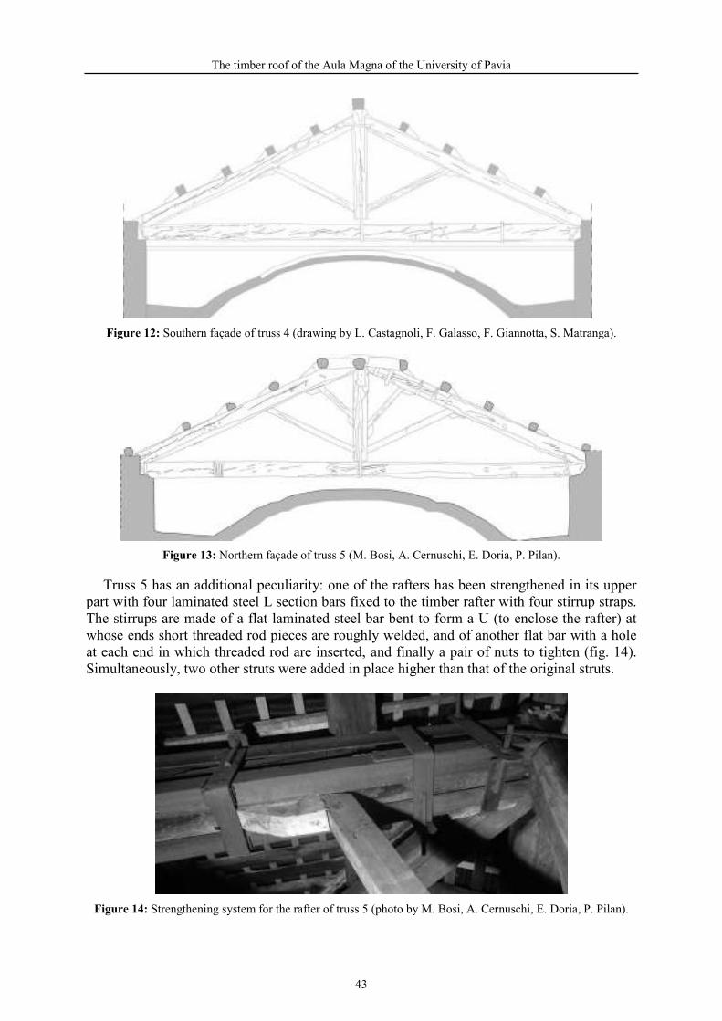
The timber roof of the Aula Magna of the University of Pavia
Southern façade of truss 4 (drawing by L. Castagnoli, F. Galasso, F. Giannotta, S. Matranga).
Northern façade of truss 5 (M. Bosi, A. Cernuschi, E. Doria, P. Pilan).
Truss 5 has an additional peculiarity: one of the rafters has been strengthened in its upper part with four laminated steel L section bars fixed to the timber rafter with four stirrup straps. The stirrups are made of a flat laminated steel bar bent to form a U (to enclose the rafter) at whose ends short threaded rod pieces are roughly welded, and of another flat bar with a hole at each end in which threaded rod are inserted, and finally a pair of nuts to tighten (fig. 14). Simultaneously, two other struts were added in place higher than that of the original struts.
Strengthening system for the rafter of truss 5 (photo by M. Bosi, A. Cernuschi, E. Doria, P. Pilan).
43
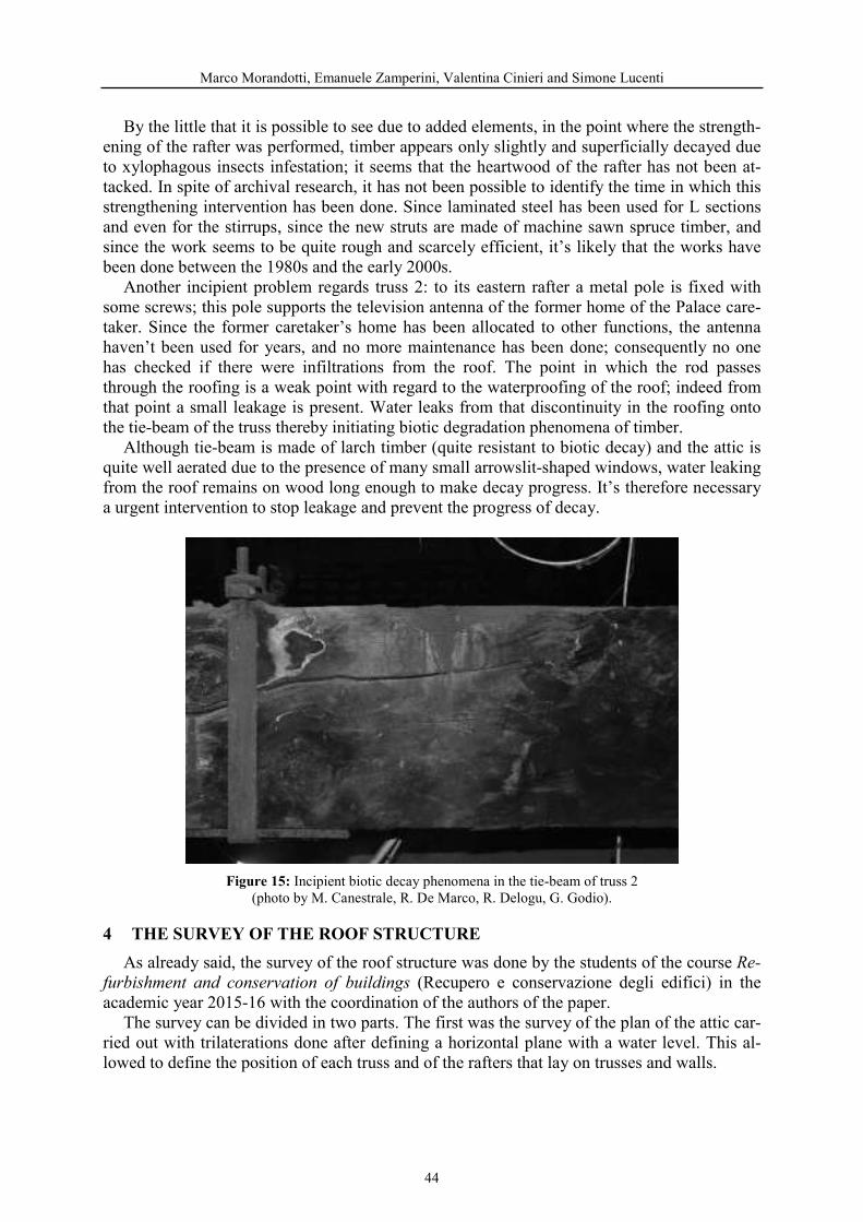
Marco Morandotti, Emanuele Zamperini, Valentina Cinieri and Simone Lucenti
By the little that it is possible to see due to added elements, in the point where the strength-ening of the rafter was performed, timber appears only slightly and superficially decayed due to xylophagous insects infestation; it seems that the heartwood of the rafter has not been at-tacked. In spite of archival research, it has not been possible to identify the time in which this strengthening intervention has been done. Since laminated steel has been used for L sections and even for the stirrups, since the new struts are made of machine sawn spruce timber, and since the work seems to be quite rough and scarcely efficient, it’s likely that the works have been done between the 1980s and the early 2000s.
Another incipient problem regards truss 2: to its eastern rafter a metal pole is fixed with some screws; this pole supports the television antenna of the former home of the Palace care-taker. Since the former caretaker’s home has been allocated to other functions, the antenna haven’t been used for years, and no more maintenance has been done; consequently no one has checked if there were infiltrations from the roof. The point in which the rod passes through the roofing is a weak point with regard to the waterproofing of the roof; indeed from that point a small leakage is present. Water leaks from that discontinuity in the roofing onto the tie-beam of the truss thereby initiating biotic degradation phenomena of timber.
Although tie-beam is made of larch timber (quite resistant to biotic decay) and the attic is quite well aerated due to the presence of many small arrowslit-shaped windows, water leaking from the roof remains on wood long enough to make decay progress. It’s therefore necessary a urgent intervention to stop leakage and prevent the progress of decay.
Incipient biotic decay phenomena in the tie-beam of truss 2 (photo by M. Canestrale, R. De Marco, R. Delogu, G. Godio).
As already said, the survey of the roof structure was done by the students of the course (Recupero e conservazione degli edifici) in the
academic year 2015-16 with the coordination of the authors of the paper. The survey can be divided in two parts. The first was the survey of the plan of the attic car-
ried out with trilaterations done after defining a horizontal plane with a water level. This al-lowed to define the position of each truss and of the rafters that lay on trusses and walls.
44

The timber roof of the Aula Magna of the University of Pavia
The second part of the survey is the survey of the trusses. First of all an horizontal refer-ence line was defined with the water level and materialized on the tie-beams with a string. A different horizontal line was defined for each truss with reference to its peculiarities, but each truss could be positioned in relation to others thanks to the general horizontal level already fixed. After this, on each rafter and post a string was placed; the exact position of these strings could be defined using the plumb line. Thanks to the so built “string skeleton” the dimensions of the timber elements could be measured and properly fixed in the vertical plan: in various points of the string a section of the element was surveyed, measuring the distance of the upper and lower part of the timber from the string. Finally, the envelope of the sections allowed to draw the façades of the trusses. Also the construction details of the joints were surveyed with reference to the string skeleton, in order to have the certainty of a high level of precision.
During the research, a preliminary structural model of the roof was realized. The model in-cludes the six trusses, the rafters at the hip ends and all the purlins. External loads have been applied to purlins as an uniformly distributed load. Given the large sections of timber ele-ments used for both trusses and for rafters and purlins, none of the components of the roof is subjected to significant stresses.
However the analysis gives some useful information about the roof: the most stressed ele-ments are the rafters placed on the median of the hip ends, followed by the straining beams of the queen posts that are subject both to relevant bending moment and to compression. The high stresses in the rafter at the hip ends testify the impossibility to built the roof as it was de-scribed in the manuscript by Marchesi with hip ends having the same slope of other pitches: indeed in that case, the rafter would have the same length and loads of real roof, but no inter-mediate support thus being overly stressed.
Structural scheme of the timber structure of the roof: diagrams of bending moments.
Another useful information regards truss 5 in which the new struts are added. As it was easy to predict, the effect of the new struts is negative, indeed they increase the stresses in the rafter, instead of reducing them. Thanks to the load of two purlins, the upper part of the rafter
45
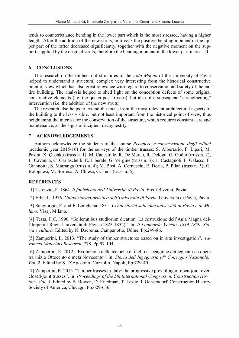
Marco Morandotti, Emanuele Zamperini, Valentina Cinieri and Simone Lucenti
tends to counterbalance bending in the lower part which is the most stressed, having a higher length. After the addition of the new struts, in truss 5 the positive bending moment in the up-per part of the rafter decreased significantly, together with the negative moment on the sup-port supplied by the original struts; therefore the bending moment in the lower part increased.
The research on the timber roof structures of the of the University of Pavia helped to understand a structural complex very interesting from the historical constructive point of view which has also great relevance with regard to conservation and safety of the en-tire building. The analysis helped to shed light on the conception defects of some original constructive elements (i.e. the queen post trusses), but also of a subsequent “strengthening” intervention (i.e. the addition of the new struts).
The research also helps to extend the focus from the most relevant architectural aspects of the building to the less visible, but not least important from the historical point of view, thus heightening the interest for the conservation of the structure, which requires constant care and maintenance, as the signs of incipient decay testify.
Authors acknowledge the students of the course (academic year 2015-16) for the surveys of the timber trusses: S. Albertario, F. Lipari, M. Pasini, X. Qushku (truss n. 1); M. Canestrale, R. De Marco, R. Delogu, G. Godio (truss n. 2); L. Cavanna, C. Garlaschelli, E. Liberale, G. Vergine (truss n. 3); L. Castagnoli, F. Galasso, F. Giannotta, S. Matranga (truss n. 4); M. Bosi, A. Cernuschi, E. Doria, P. Pilan (truss n. 5); G. Bolognesi, M. Borreca, A. Chiesa, G. Ferri (truss n. 6).
[1] Terenzio, P. 1864. . Eredi Bizzoni, Pavia. [2] Erba, L. 1976. . Università di Pavia, Pavia. [3] Sangiorgio, P. and F. Longhena. 1831.
. Visaj, Milano. [4] Testa, F.C. 1996. “Sollemnibus studiorum dicatum. La costruzione dell’Aula Magna del-l’Imperial Regia Università di Pavia (1825-1852)”. In:
Edited by N. Dacrema. Campanotto, Udine, Pp:249-86. [5] Zamperini, E. 2013. “The study of timber structures based on in situ investigation”.
, 778, Pp:97-104. [6] Zamperini, E. 2012. “Evoluzione delle tecniche di taglio e segagione dei legnami da opera tra inizio Ottocento e metà Novecento”. In:
Edited by S. D’Agostino. Cuzzolin, Napoli, Pp:729-40. [7] Zamperini, E. 2015. “Timber trusses in Italy: the progressive prevailing of open-joint over closed-joint trusses”. In:
Edited by B. Bowen, D. Friedman, T. Leslie, J. Ochsendorf. Construction History Society of America, Chicago, Pp:629-636.
46

HISTORICAL BUILDING WITH TIMBER FRAME IN THE LIGURIA REGION: AN INVENTORY PROPOSAL
Anna Bruzzone1, Riccardo Forte 2, Silvia Gelvi1, Daniela Pittaluga3, Felice Ragazzo4, Linda Secondini1, Gerolamo Stagno5
1Architect 2Architect PHD Universite Paris 1 Panthéon-Sorbonne
Architect PHD U iversity of Ge oa Politec ic Faculty DA&D Ge oa Art of Wood Desig Professor U iversity of Sapie za Ro e Architect Specialist i Mo u e t Restauratio STD Ge ova
Keywords: Timber frame structures, historical buildings, assessment, analysis, diagnosis
Abstract
The Liguria region emphasizes a widespread and little known historical asset with timber framing structures dated back to the 19th and 20th century.
The herein contribution derives fromstudies included in some thesis1 developed in the Dipartimento di Architettura e Design of Università di Genova with the cooperation of several public institution and professors of other universities. An essential tool for the conservation, generally speaking, of the cultural heritage, is its knowledge. To that purpose this contribution proposes a template aimed at inventorying timber framed buildings in the Liguria region.
The template follows a tree-like structure, so that information can be recorded from the scale of the whole construction to the single parts constituting the wooden framed masonry. It includes the geometrical features of the building emphasizing possible irregularities in plan and along the height, from which torsional motions could trigger under earthquakes. Other fields of the template follow the hierarchical organization that characterizes wooden structure divided in members and structural units connected by joints and auxiliary beams to form a structural system. For such combination, the template provides data on the geometry, dimensions and regarding materials features relatively to the stone and mortar type and to the wooden specie of the framing. The degrade is also listed and is detected by means of several types of laboratories and in situ tests. It is divided in the template in that derived from causes of mechanical nature and due to biotical agent, deducing the reliability level of the load bearing structure.
47
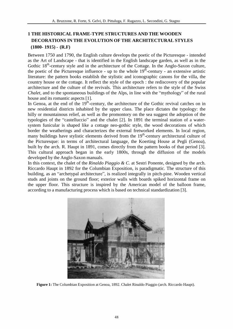
A. Bruzzone, R. Forte, S. Gelvi, D. Pittaluga, F. Ragazzo, L. Secondini, G. Stagno
1 THE HISTORICAL FRAME-TYPE STRUCTURES AND THE WOODEN DECORATIONS IN THE EVOLUTION OF THE ARCHITECTURAL STYLES
(1800- 1915) - (R.F)
Between 1750 and 1790, the English culture develops the poetic of the Picturesque - intended as the Art of Landscape - that is identified in the English landscape garden, as well as in the Gothic 18th-century style and in the architecture of the Cottage. In the Anglo-Saxon culture, the poetic of the Picturesque influence - up to the whole 19th-century - an extensive artistic literature: the pattern books establish the stylistic and iconographic canons for the villa, the country house or the cottage. It reflect the style of the epoch : the rediscovery of the popular architecture and the culture of the revivals. This architecture refers to the style of the Swiss Chalet, and to the spontaneous buildings of the Alps, in line with the “mythology” of the rural house and its romantic aspects [1]. In Genoa, at the end of the 19th-century, the architecture of the Gothic revival catches on in new residential districts inhabited by the upper class. The place dictates the typology: the hilly or mountainous relief, as well as the promontory on the sea suggest the adoption of the typologies of the “castelluccio” and the chalet [2]. In 1891 the terminal station of a water- system funicular is shaped like a cottage neo-gothic style, the wood decorations of which border the weatherings and characterizes the external fretworked elements. In local region, many buildings have stylistic elements derived from the 19th-century architectural culture of the Picturesque: in terms of architectural language, the Koerting House at Pegli (Genoa), built by the arch. R. Haupt in 1891, comes directly from the pattern books of that period [3]. This cultural approach began in the early 1800s, through the diffusion of the models developed by the Anglo-Saxon manuals. In this context, the chalet of the Rinaldo Piaggio & C. at Sestri Ponente, designed by the arch. Riccardo Haupt in 1892 for the Columbian Exposition, is paradigmatic. The structure of this building, as an “archetypal architecture”, is realized integrally in pitch-pine. Wooden vertical studs and joints on the ground floor; exterior walls with boards spiked horizontal frame on the upper floor. This structure is inspired by the American model of the balloon frame, according to a manufacturing process which is based on technical standardization [3].
Figure 1: The Columbian Exposition at Genoa, 1892. Chalet Rinaldo Piaggio (arch. Riccardo Haupt).
48
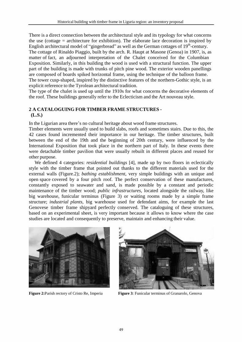
Historical building with timber frame in Liguria region: an inventory proposal
There is a direct connection between the architectural style and its typology for what concerns the use (cottage = architecture for exhibition). The elaborate lace decoration is inspired by English architectural model of “gingerbread” as well as the German cottages of 19th-century. The cottage of Rinaldo Piaggio, built by the arch. R. Haupt at Masone (Genoa) in 1907, is, as matter of fact, an adjourned interpretation of the Chalet conceived for the Columbian Exposition. Similarly, in this building the wood is used with a structural function. The upper part of the building is made with trunks of pitch pine wood. The exterior wooden panellings are composed of boards spiked horizontal frame, using the technique of the balloon frame. The tower cusp-shaped, inspired by the distinctive features of the northern-Gothic style, is an explicit reference to the Tyrolean architectural tradition. The type of the chalet is used up until the 1910s for what concerns the decorative elements of the roof. These buildings generally refer to the Eclecticism and the Art nouveau style.
2 A CATALOGUING FOR TIMBER FRAME STRUCTURES - (L.S.)
In the Ligurian area there’s no cultural heritage about wood frame structures. Timber elements were usually used to build slabs, roofs and sometimes stairs. Due to this, the 42 cases found incremented their importance in our heritage. The timber structures, built between the end of the 19th and the beginning of 20th century, were influenced by the International Exposition that took place in the northern part of Italy. In these events there were detachable timber pavilion that were usually rebuilt in different places and reused for other purpose.
We defined 4 categories: residential buildings [4], made up by two floors in eclectically style with the timber frame that pointed out thanks to the different materials used for the external walls (Figure.2); bathing establishment, very simple buildings with an unique and open space covered by a four pitch roof. The perfect conservation of these manufactures, constantly exposed to seawater and sand, is made possible by a constant and periodic maintenance of the timber wood; public infrastructures, located alongside the railway, like big warehouse, funicular terminus (Figure 3) or waiting rooms made by a simple frame structure; industrial plants, big warehouse used for defendant aims, for example the last Genovese timber frame shipyard perfectly conserved. The cataloguing of these structures, based on an experimental sheet, is very important because it allows to know where the case studies are located and consequently to preserve, maintain and enhancing their value.
Figure 2:Parish rectory of Cristo Re, Imperia Figure 3: Funicular terminus of Granarolo, Genova
49

A. Bruzzone, R. Forte, S. Gelvi, D. Pittaluga, F. Ragazzo, L. Secondini, G. Stagno
2.1 Experimental sheet – (S.G.) To understand the building techniques of the timber structures, we elaborated an experimental sheet. Moreover, it tries to underline the analogies between them. Our aim is to create an experimental practical code for frame structures, in order to systematically classify and store the building procedures. We reserve therefore a chance to provide constructive assumptions as compatible with the visible structure. Many of the buildings are in use or inhabited and it was a limit because the characterizing elements couldn’t be analysed with an invasive approach. We reserve therefore a chance to provide constructive assumptions as compatible with the visible structure [5].
This sheet is divided into two sections; the first one on macroscale level, while the second one on a microscale focus, pointing out the technical details. We move on to a deeper analysis of the building, making a difference between the elements of the load bearing structure and the envelope ones. The sheet has drawing list of all the relevant element of a timber structure aimed to help and understand quickly the case study An important section is focused on timber’s durability to find out the better intervention aimed to maintain and preserve the buildings (Figure 4).
Figure 4: Joint schedule of the experimental sheet
2.2 Analysis of the degradation phenomena – (A.B.) Once obtained a complete overview of the existence of several wooden framed buildings in the territory of Liguria, the detection of the health conditions for the whole structures were required in order to prepare a common maintenance plan for all the located buildings.
For a detailed understanding of the storage conditions at the current state it has been necessary to develop a fast compile-method, complete and applicable to all buildings which takes into account both the nature and the location of any degradation phenomena. The purpose of such identification and meticulous filling, that goes beyond the normal survey practice that uses standardized tables to be filed in the pipeline for each wooden element, is the identification of what are the recurrent degradation phenomena, found in most buildings and what the causes.
For this aim has been prepared a questionnaire to support standard compile-filing, wherein is provided a space for a manual relief.
50
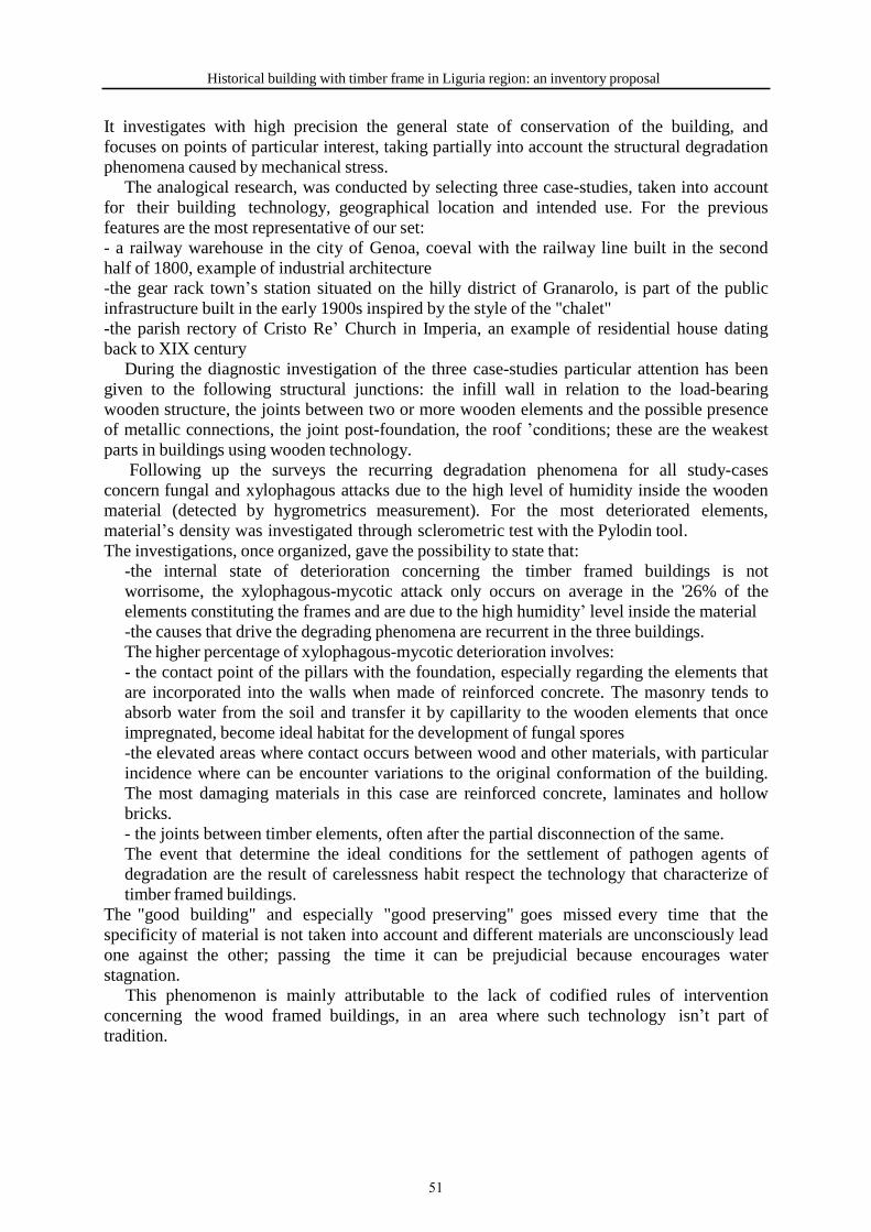
Historical building with timber frame in Liguria region: an inventory proposal
It investigates with high precision the general state of conservation of the building, and focuses on points of particular interest, taking partially into account the structural degradation phenomena caused by mechanical stress.
The analogical research, was conducted by selecting three case-studies, taken into account for their building technology, geographical location and intended use. For the previous features are the most representative of our set: - a railway warehouse in the city of Genoa, coeval with the railway line built in the second half of 1800, example of industrial architecture -the gear rack town’s station situated on the hilly district of Granarolo, is part of the public infrastructure built in the early 1900s inspired by the style of the "chalet" -the parish rectory of Cristo Re’ Church in Imperia, an example of residential house dating back to XIX century
During the diagnostic investigation of the three case-studies particular attention has been given to the following structural junctions: the infill wall in relation to the load-bearing wooden structure, the joints between two or more wooden elements and the possible presence of metallic connections, the joint post-foundation, the roof ’conditions; these are the weakest parts in buildings using wooden technology. Following up the surveys the recurring degradation phenomena for all study-cases concern fungal and xylophagous attacks due to the high level of humidity inside the wooden material (detected by hygrometrics measurement). For the most deteriorated elements, material’s density was investigated through sclerometric test with the Pylodin tool. The investigations, once organized, gave the possibility to state that:
-the internal state of deterioration concerning the timber framed buildings is not worrisome, the xylophagous-mycotic attack only occurs on average in the '26% of the elements constituting the frames and are due to the high humidity’ level inside the material -the causes that drive the degrading phenomena are recurrent in the three buildings. The higher percentage of xylophagous-mycotic deterioration involves: - the contact point of the pillars with the foundation, especially regarding the elements that are incorporated into the walls when made of reinforced concrete. The masonry tends to absorb water from the soil and transfer it by capillarity to the wooden elements that once impregnated, become ideal habitat for the development of fungal spores -the elevated areas where contact occurs between wood and other materials, with particular incidence where can be encounter variations to the original conformation of the building. The most damaging materials in this case are reinforced concrete, laminates and hollow bricks. - the joints between timber elements, often after the partial disconnection of the same. The event that determine the ideal conditions for the settlement of pathogen agents of degradation are the result of carelessness habit respect the technology that characterize of timber framed buildings.
The "good building" and especially "good preserving" goes missed every time that the specificity of material is not taken into account and different materials are unconsciously lead one against the other; passing the time it can be prejudicial because encourages water stagnation. This phenomenon is mainly attributable to the lack of codified rules of intervention concerning the wood framed buildings, in an area where such technology isn’t part of tradition.
51

A. Bruzzone, R. Forte, S. Gelvi, D. Pittaluga, F. Ragazzo, L. Secondini, G. Stagno
3 DIAGNOSTIC SURVEY – (G.S.)
The construction knowledge, especially in historical building, is based not only on visual observation. Requisite is to assess the conservation status to define the proceeding due to maintenance. In this specific case we applied the complete methodology using non-destructive tests to obtain a classification, according to the guide lines of Norm UNI 11119 [6] for existing elements, supplement with the ones of UNI 11035-1/2/3. [7] To understand the wood species, we used macroscopic and microscopic analysis with precision instruments that analyze wood cores and slices samples parallel or perpendicular to grain as the UNI 11118 suggests.[8]( Figure 5-6)
Through in situ reliefs we find out the wood moisture applying experimentally the Norm UNI [9] and we carried out data detected on three directions of the element’s grain, analyzing it in different positions of the elements in relation to vulnerability, for example in the heads or in the middle of the beams.
Figure 5:Microtome used to cut extremly thin slices Figure 6: Wood core extracted from a beam.
The assessment of density was carried out using the sclerometer Pilodyn (Figure 7) or the Mechanical DRC Wood Pecker, in some cases incremented with an experimental sclerometer with an elliptical nail.This mechanical test is limited cause the nail is 5 cm long and can’t evaluate the whole section of the beam. For a better assess we used an electronical hammer RESI F 400 (Figure 8) that create dendrogramm diagram to evaluate instantly the beam and increment the next measures. The presence of xilophagan insects was examined by auscultation with AUDIOTERMES HELPEST 21; this analysis, parts of a thesis degree [10], was applied both to bearing and not- bearing elements. We find different situations related to the environmental parameter because the timber framed structure are located near the sea or on the hills behind the city at an altitude of 500 meters. Monitoring the structure during an year allow to better understand their behavior and the durability data of the wooden elements. In the experimental sheet is important to remark the different and various articles insert, that even define the kind of joint or connection of each single element. This is important because it is a step forward to increment a topic not developed by the Technical Norm.
52

Historical building with timber frame in Liguria region: an inventory proposal
Figure 7: Mechanical Sclerometer Pylodyn Figure 8: Resi F.400
4 THE JOINTS OF THE TIMBER FRAME STRUCTURE BETWEEN XIX AND XX CENTURY AND THE TIMBER CONSTRUCTION IN LIGURIA - (F.R.)
In Italy between XIX and XX century, the joints of the timber frame structures were inspired by the essays of three important authors: Nicola Cavalieri San Bertolo [11], Bartolomeo Saldini [12], Francesco Masciari-Genoese [13]. In general, these essays are referred to similar french treaties. As regard, industrial aspect or properly productive, is basilar to focus on the pioneering activity of Cavalier Ferruccio Gay, who works at the beginning of ‘900. The factory, no longer existing, has the registered office in Via Labicana 126 in Rome, not very far from Colosseum, in front of Basilica of San Clemente. According to Ing. Adolfo Mazza, the founder of the ETERNIT society that create not an essay, but a consistent and various catalog for commercial purpose, Cav. Gay decided “to dress” his timber frames structures with cement and asbesto’s panels. About this, in this period, the material wasn’t considered critical harmfull, as demonstrate in the last years. The wooden prefab activity of Cav. Gay developed substantially in four directions: the fast assembly requirement for the colonial italian expansion in the northern part of Africa; the requirement of emergency structures to face the severe seismic events in Stretto of Messina – Reggio Calabria in 1908 and in Piana del Fucino in 1915; the requirement of light-weight structures for the developing of the new railway; the trade of prefab constructions for tourist places, leisure and wellness, similar to the high minded residences.
According to what we know today, in addition to roman house, there is a detailed data about a villa built in Reggio Calabria in 1909, lost due to a fire, and another coeval one in Messina, no longer existing. There are some vague notice and data about a series of constructions in the libian’s territory and about another structure in the thermal city of Fiuggi, not very far from Rome. However the most beautiful and significant ones that Cav. Gay produced are in Via Giordano Bruno in Genova. This two residential buildings are based on different architectonical vision; the first, similar to the roman’s house, shows a motif of decoration in Liberty style; the second one instead shows a prevalence of synthetic volumes. Regardless of the architectonic vision, the structural aspect is composed by a the timber frame with double layer of wooden planks and in the exterior side by Eternit panels. In the vertical beams, sometimes more than two meters long, the planks are stiffed by iron forks seated in iron elements fixed on the planks with screws. This particular kind of connection ensure that the gutter planks, created for the heads of the beams, take parts of a more complex connection method. The bearing beam are jonted with “side-halved”,”stop-splayed scarf with key”(Figure
53

A. Bruzzone, R. Forte, S. Gelvi, D. Pittaluga, F. Ragazzo, L. Secondini, G. Stagno
9) or “dovetail”. In some cases the beams are simply drew close and connected by iron tiebeams or bolts. In conclusion , iron hand made elements are usually used in each situation of elements convergence. (Figure 10)
Figure 9: “stop-splayed scarf with key” joint that connect two sleeper in the foundation. San Sperato House (Reggio Calabria); similar to the one of Cav. Ferruccio Gay at the beginning of ‘900.
Figure 10: Metallic handmade elements to stiff and reinforce angle beams in the upper part of the structure. San Sperato House (Reggio Calabria); similiar to the one of Cav. Ferruccio Gay at the beginning of ‘900.
5 CONSERVATION AN RESTORATION: IDEOLOGICAL CONSIDERATION – (D.P.)
Architectural Heritage of wooden frame structures is a particular component of the Ligurian heritage. We cannot say that it is an essential component but still it deserves attention and study. A research was undertaken a few years ago at the University of Genoa - DSA - Department of Sciences for Architecture (now DAD - Department of Architecture and Design) [10] to assess how this particular construction technology was present in Liguria; surprisingly the inspections on the territory showed that more structures were preserved than previously thought. Then the investigation continued, developing a methodology of observation and recording, and elaborating a real own survey card that would allow to collect as much information as possible on these structures. At the end of this phase we interpreted data
54

Historical building with timber frame in Liguria region: an inventory proposal
critically, trying to grasp the reasons for the usage of this particular wood technology in a region, such as Liguria, rather reluctant to use such a material. An interesting result: in certain historical moments, there was a particular increase and diffusion of wood frame structures thanks to some models developed during the International Exhibitions that took place in the late Nineteenth and early part of the Twentieth century; these models, suitably revised and adapted, were then replicated in contemporary buildings.
Does it make sense to recover and maintain this heritage? In this regard, the words of a theorist of restoration, great master Alois Riegl [14], appear to be very relevant. Several times in his writings he says that normally there is not an absolute value in the architectural heritage, it only has a relative value, related to its importance for its specific territory. But Riegl said also that in certain cases an absolute value is present: if an heritage represents a singular point in the evolution of a production line, if it namely has determined an important step, leading to innovations compared to the previous production, if it heavily conditioned subsequent production, in those cases even a relatively modest building becomes a “Special Architectonic Heritage”, and it must be protected and preserved in any case.
The framed wooden houses in Ligurian region, to all intents and purposes, may as well be such a case, despite their small number. For sure they constitute a singular element, a special building technique for those times, conceived with peculiar perspective. Losing these structures, losing these elements would mean losing a significant part of the building history of this region, it means losing a part of history that is intertwined and fused with international history.
Conservation of this heritage, avoidance of its loss means first knowing it and documenting it and then to adopt good maintenance practices [15]; so even if the material itself, presents some vulnerabilities, you can pass on to future generations this important cultural heritage. (D.P.)
REFERENCES
[1]. Patetta L. 1991. L’architettura dell’eclettismo. Fonti, teorie, modelli 1750-1900, Milan, Città Studi, , Pp: 9-41. [2]. Giubilei M.F. 1990. “Materiali per una storia dell’architettura neogotica genovese di fine secolo”. In Il Neogotico nel XIX e XX secolo, Edited by R. Bossaglia and V. Terraroli, Milan, Mazzotta, vol. II., Pp: 63, 66-67. [3]. 1886. “Chalets. Bozzetti R. Haupt Arch. - Scala 1:100”. Ricordi di Architettura. [4] Pesso L., Sul consolidamento delle fabbriche nelle Calabrie contro i danni dei terremoti, Parma, 1895 [5] Pittaluga D., Stratificazioni lignee: problemi di lettura, interpretazione e conservazione, in Atti del convegno internazionale “ Conservare e restaurare il legno”, Bressanone 2009, ed. Arcadia ricerche , Venezia 2009, pp. 95-106 [6] UNI 11119 NORMA ITALIANA BENI CULTURALI MANUFATTI LIGNEI Strutture Portanti degli Edifici Ispezione in situ per la diagnosi degli elementi in opera Luglio 2004 [7] UNI 11035-1 NORMA ITALIANA Legno Strutturale CLASSIFICAZIONE A VISTA DEI LEGNAMI SECONDO LA RESISTENZA MECCANICA Parte 1 Terminologia e misurazione delle caratteristiche APRILE 2010 [8] UNI 11118 NORMA ITALIANA BENI CULTURALI MANUFATTI LIGNEI CRITERI PER L’DENTIFICAZIONE DELLE SPECIE LEGNOSE MAGGIO 2004 [9] UNI EN 13183 -2 UMIDITA’ LEGNO STIMA TRAMITE METODO ELETTRICO 2003
55
A. Bruzzone, R. Forte, S. Gelvi, D. Pittaluga, F. Ragazzo, L. Secondini, G. Stagno
[10] S.Gelvi –L.Secondini, Studi e Ricerche Su Sistemi Intelaiati In Legno in ambito ligure, Conoscere per conservare.Rel.Prof Arch D.Pittaluga Correl. Prof Ing G.Mor Arch G.Stagno Univ.tè degli Studi di Genova Scuola Politecnica Dip.to DA&D 2016-2017 A.Bruzzone Stato di Conservazione degli edifici antichi a telaio ligneo. Indagine conoscitiva delle strutture storiche in territorio Ligure Rel.re Prof Arch Daniela Pittaluga Corel. Ri Prof Dott Scienze Forest.li Marco Togni Arch G.Stagno [11] Cavalieri, San Bertolo, N., Istituzioni di Architettura Statica e Idraulica, R. Petraroja Editore, Napoli, 1868-69. [12] Saldini, B., L’architettura del legno, Tipografia degli Ingegneri, Milano, 1886-1888. [13] Masciari-Genoese, F., Trattato di costruzioni antisismiche, Ulrico Hoepli Editore, Milano, 1915. [14] S.Scarrocchia, A.Riegl: theory and practice of the preservation of monuments. Anthology of writings, speeches, reports 1898-1905, with a choice of critical essays, Bologna, CLUEB, 1995. See also B. P. Torsello, "What is restoration? Nine scholars in comparison", Marsilio Editori, Venezia, [15] D. Pittaluga, “ Questioni di Archeologia dell’Architettura e Restauro” , ed. Ecig, Genoa 2009.
56

TIMBER STRUCTURES IN GEORGIAN CULTURAL HERITAGE (FOR CASE OF SOUTHERN GEORGIA, REGION SAMTSKHE-JAVAKHETI)
A. Tamar Khoshtaria 1, B. Nino Chachava 2, C. Malkhaz Lekveishvili 3
1 2 Georgian Technical University, Faculty of Architecture, Urban Planning and Design, Tbilisi, Georgia
3 Nple “Engineering Idea”, Kote Afxazi Str.18/2, 0105 Tbilisi, Georgia
Keywords: Timber Structures, Cultural Heritage, Preservation, Tourism Cluster
Abstract
Cultural heritage in Samtskhe-Javakheti Region of Southern Georgia needs urgent rehabilitation activities. Renovation and care of Timber building constructions is very important for the preservation of historical appearance, identity and tourism sector devel- opment - leading branch of the region. Wooden architecture of Georgia has a long history. In west Georgia timber decorative balconies were common. In Southern Georgia, there are houses from Middle Ages with special type of timber ceiling design.
In Samtskhe-Javakheti from 19-th century original type of wooden construction has formed, as mixture of Russian and German experience, established on Georgian ground and fulfilled with local materials. This approach created absolutely unique architectural samples, most of those can be found in resort cities of Borjomi municipality and resort Abastumani. Partly these buildings are constructed from mixed materials like stone, bricks, others are completely wooden. Usage of wood can be found also in stone buildings, as design of roofing construction, columns, lace styled frontons and lodges. Many buildings are constructed with a technic of Fachwerk. Timber heritage is very typical for resorts of Samtskhe-Javakheti. Buldings are con- structed with healthy, hard pine timber. It can be explained with good tradition of wood pro- cessing technology from the right time of three logging until last processing; with usage of natural varnishes, paints and anti-fungal treatments. The official list of architectural heritage houses of Borjomi is available by the municipality. In Abastumani there are up to 122 cultural heritage buildings decorated with timber details. Wooden log houses of 19-th and 20-th century can also be founded in resorts Tsagveri and Bakuriani, there nice family hotels are arranged.
Preserving, care of unique wooden architecture is very important for identity of region and country, development of sustainable tourism. In framework of our research we consider structural and style peculiarities for each case.
57

A. Tamar Khoshtaria, B. Nino Chachava and C. Malkhas Lekveishvili
1 INTRODUCTION
Samtskhe-Javakheti region is a wide and very specific region in Southern Georgia. Samtskhe-Javakheti was called “Southern Georgian Gate” due to the geopolitical conditions, trade ways and cultural features. Region with its administrative center Akhaltsikhe is also a communication hub and is bordering to Turkey and Armenia. Samtskhe-Javakheti region comprises recently 6 Municipalities: Adigeni, Akhaltsikhe, Akhalkalaki, Aspindza, Borjomi and Ninotsminda. Adigeni, Akhaltsikhe and Aspindza districts were included in the historic province Samtskhe; Borjomi’s old name is Tori; Akhalkalaki and Ninotsminda districts are equal to the historical Javakheti Province. “Samtskhe-Javakheti is the oldest historic territory of Georgia and is considered as the cradle of Georgian culture.” [1]
1.1 Brief Description Samtskhe-Javakheti Region is characterized by the lot of touristic attractions. These are
several protected landscapes: Natural Park of Borjomi-Kharagauli, Strict nature reserve of Borjomi, managed reserves: Ktsia-Tabatskuri, Tetrobi and protected areas of Javakheti: Ja- vakheti national park, Sulda, Kartsakhi, Khantchali, Budgasheni and Madatafi managed re- serves. Great touristic routes passes through this region. Numerous ancient and medieval cultural heritage monuments fascinates its guests: Vardzia, cave monastery complex, called city of caves; Sapara, Zarzma, Timotesubani, Tchulevi and other monasteries; Khertvisi, Tmogvi, Atskuri fortresses and numerous other cultural monuments declare about long histo- ry of this area. Between them are different types of buildings, beginned by ancient and medie- val dwellings with timber ceilings in Meskhetian villages Saro and Tchatchraki of Aspindza Municipality, up to city cultural heritage houses of 19th and the beginning of 20th centuries in resorts Borjomi and Abastumani, which are rich on timber construction details and mixed techiques. Building materials, wood and stone, are mainly local. Wood supply of Samtskhe- Javakheti was used also for construction of the city heritage buildings in past centuries in the Capital of Georgia, Tbilisi. Tourism is one of the leading branches of the country and also for Samtskhe-Javakheti region. The group of the resorts and recreation places could be defined as Tourism and recreation cluster of Samtskhe-Javakheti. This cluster includes well known re- sorts like Borjomi and Abastumani, and less known settlements, which can become tourism attraction places in near future. Under this conditions is very important to pay attention to the beautiful architectural heritage, to develop programs, plans and projects for the preservation, protection and rehabilitation. Greatest attraction places are rich on cultural heritage, and long- term approach is significant for the sustainable results.
1.2 Objectives Objectives of this article are to analyse the types of medieval dwellings and later 19th cen-
tury living houses, which are outstanding with their timber constructions and decorative carv- ing elements between great number of Samtskhe-Javakheti’s cultural heritage.
1.3 Methodology For this research were used the graphical, technical and economical data materials based
on existing historical heritage data; architectural - archeological drawings, 3D Scanning and CAD technology. Projects of the architectural and engineering company “Engineering Idea” were considered.
58
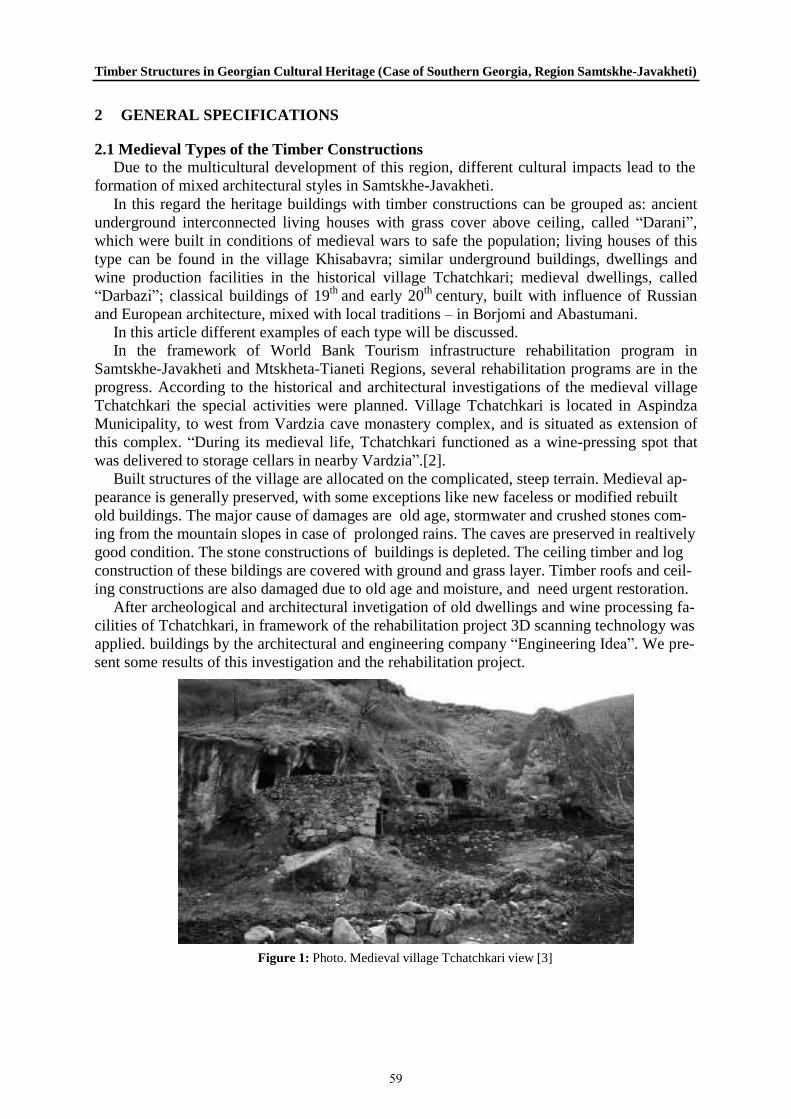
Timber Structures in Georgian Cultural Heritage (Case of Southern Georgia, Region Samtskhe-Javakheti)
2 GENERAL SPECIFICATIONS
2.1 Medieval Types of the Timber Constructions Due to the multicultural development of this region, different cultural impacts lead to the
formation of mixed architectural styles in Samtskhe-Javakheti. In this regard the heritage buildings with timber constructions can be grouped as: ancient
underground interconnected living houses with grass cover above ceiling, called “Darani”, which were built in conditions of medieval wars to safe the population; living houses of this type can be found in the village Khisabavra; similar underground buildings, dwellings and wine production facilities in the historical village Tchatchkari; medieval dwellings, called “Darbazi”; classical buildings of 19th and early 20th century, built with influence of Russian and European architecture, mixed with local traditions – in Borjomi and Abastumani.
In this article different examples of each type will be discussed. In the framework of World Bank Tourism infrastructure rehabilitation program in
Samtskhe-Javakheti and Mtskheta-Tianeti Regions, several rehabilitation programs are in the progress. According to the historical and architectural investigations of the medieval village Tchatchkari the special activities were planned. Village Tchatchkari is located in Aspindza Municipality, to west from Vardzia cave monastery complex, and is situated as extension of this complex. “During its medieval life, Tchatchkari functioned as a wine-pressing spot that was delivered to storage cellars in nearby Vardzia”.[2].
Built structures of the village are allocated on the complicated, steep terrain. Medieval ap- pearance is generally preserved, with some exceptions like new faceless or modified rebuilt old buildings. The major cause of damages are old age, stormwater and crushed stones com- ing from the mountain slopes in case of prolonged rains. The caves are preserved in realtively good condition. The stone constructions of buildings is depleted. The ceiling timber and log construction of these bildings are covered with ground and grass layer. Timber roofs and ceil- ing constructions are also damaged due to old age and moisture, and need urgent restoration.
After archeological and architectural invetigation of old dwellings and wine processing fa- cilities of Tchatchkari, in framework of the rehabilitation project 3D scanning technology was applied. buildings by the architectural and engineering company “Engineering Idea”. We pre- sent some results of this investigation and the rehabilitation project.
Figure 1: Photo. Medieval village Tchatchkari view [3]
59

A. Tamar Khoshtaria, B. Nino Chachava and C. Malkhas Lekveishvili
Main principles are to keep maximum authenticity, usage of traditional construction meth- ods and local building materials. The rehabilitation project includes reinforcement of founda- tions, walls and ceilings; waterproofing measurements, restoring of ceiling logs and timber constructions and all necessary activities to preserve and protect unique medieval village.
Figure 2: Photos of Tchatchkari dwellings. Medieval log and timber ceiling constructions.
Figure 3: Medieval village Tchatchkari rehabilitation project, timber ceiling example
60

Timber Structures in Georgian Cultural Heritage (Case of Southern Georgia, Region Samtskhe-Javakheti)
These dwellings are partially under the ground and the roofing is covered with green plant- ing. The timber constructions of the ceiling are preserved up today. Protecting of the heritage was enhanced by the planning of waterproofing and reinforcement measurements.
Figure 4: Tchatchkari. Sections of the building, existing and planned conditions
Samtskhe-Javakheti called also Meskheti in Middle ages. Meskhetian Darbazi is the next type of the medieval dwellings, using timber techniques. Darbazi houses are presented mostly in East and Southern Georgia. In Samtskhe-Javakheti they are preserved mainly in the histori- cal mountainous village Saro, located in Aspindza Municipality, which is characterized by these types of the historical dwellings. Darbazi is a very specific timber ceiling construction which has a form of the crown, with light source in the middle. Darbazis were up to 400 sq. m., with carved decorative details in the interior. Meskhetian darbazi differs from same type of dwelling in Kartly with its better natural lighting and focus on the central oven. In Meskhe- tian type were used coniferous wood contructions. [4]. Recently Darbazis in village Saro will be restored and rehabilitated in frames of the rehabilitatiobn program of Municipal Develop- ment Fund of Georgia.
61

A. Tamar Khoshtaria, B. Nino Chachava and C. Malkhas Lekveishvili
Darbazis are really fascinating due to their original construction. From three sides building Darbazi is under the ground, similar to Daranis, and only entrance is free.
Figure 5: Meskhetian Darbazi Types [4,5]
Old Georgian technology of the wood protection was very interesting, healthy, simple, and related to the beekeeping tradition.
The historical timber constructions could resist through hundreds of years, because all steps of the wood processing were strictly preserved. From the right time of the logging, which was done in winter time, up to the storage in shadow, drying on the ventilated place and processing with protective materials. For wood protection beewax was used in Georgia. Beewax was warmed together with oil, mixed in the right proportion, and then in the warm condition applied to the wooden details several times. After such protection timber construc- tion details and carves could remain resistant against moisture, fungus and other harmful im- pacts.
2.2 Buildings of 19th and 20th century From the beginning of 19th century Georgia was influenced by the Russian Kingdom. In
Samtskhe-Javakheti occurred big changes. Russian royal court was interested in Georgian re- sorts, and they invited many professionals to investigate resort potential and to develop differ- ent branches of appropriated industry.
Climatic and balneology resorts Borjomi and Abastumani were researched due to the rich spa features: termal and mineral water sources, beautiful natural landscapes and clean, very transparent air.
Professionals, who worked under instruction of Russian nobles, were mainly Germans. German doctor A. Remmert investigated mineral water sources in Borjomi and Abastumani. He dedicated a lot of afforts to develop these resorts and also contributed to landscape archi- tecture of the resorts by the planning of public spaces, gardens and parks.
62
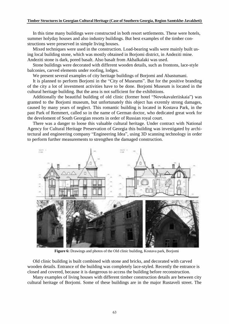
Timber Structures in Georgian Cultural Heritage (Case of Southern Georgia, Region Samtskhe-Javakheti)
In this time many buildings were constructed in both resort settlements. These were hotels, summer holyday houses and also industry buildings. But best examples of the timber con- structions were preserved in simple living houses.
Mixed techniques were used in the construction. Load-bearing walls were mainly built us- ing local building stone, which was mostly obtained in Borjomi district, in Andeziti mine. Andeziti stone is dark, pored basalt. Also basalt from Akhalkalaki was used.
Stone buildings were decorated with different wooden details, such as frontons, lace-style balconies, carved elements under roofing, lodges.
We present several examples of city heritage buildings of Borjomi and Abastumani. It is planned to perform Borjomi in the “City of Museums”. But for the positive branding
of the city a lot of investment activities have to be done. Borjomi Museum is located in the cultural heritage building. But the area is not sufficient for the exhibitions.
Additionally the beautiful building of old clinic (former hotel “Novokavaleriiskaia”) was granted to the Borjomi museum, but unfortunately this object has exremly strong damages, caused by many years of neglect. This romantic building is located in Kostava Park, in the past Park of Remmert, called so in the name of German doctor, who dedicated great work for the develoment of South Georgian resorts in order of Russian royal court.
There was a danger to loose this valuable cultural heritage. Under contract with National Agency for Cultural Heritage Preservation of Georgia this building was investigated by archi- tectural and engineering company “Engineering Idea”, using 3D scanning technology in order to perform further measurements to strengthen the damaged construction.
Figure 6: Drawings and photos of the Old clinic building, Kostava park, Borjomi
Old clinic building is built combined with stone and bricks, and decorated with carved wooden details. Entrance of the building was completely lace-styled. Recently the entrance is closed and covered, because it is dangerous to access the building before reconstruction.
Many examples of living houses with different timber construction details are between city cultural heritage of Borjomi. Some of these buildings are in the major Rustaveli street. The
63
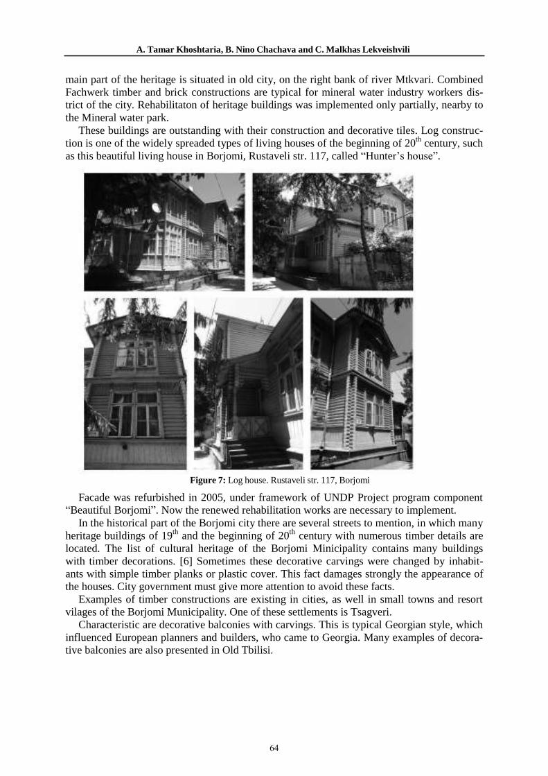
A. Tamar Khoshtaria, B. Nino Chachava and C. Malkhas Lekveishvili
main part of the heritage is situated in old city, on the right bank of river Mtkvari. Combined Fachwerk timber and brick constructions are typical for mineral water industry workers dis- trict of the city. Rehabilitaton of heritage buildings was implemented only partially, nearby to the Mineral water park.
These buildings are outstanding with their construction and decorative tiles. Log construc- tion is one of the widely spreaded types of living houses of the beginning of 20th century, such as this beautiful living house in Borjomi, Rustaveli str. 117, called “Hunter’s house”.
Figure 7: Log house. Rustaveli str. 117, Borjomi
Facade was refurbished in 2005, under framework of UNDP Project program component “Beautiful Borjomi”. Now the renewed rehabilitation works are necessary to implement.
In the historical part of the Borjomi city there are several streets to mention, in which many heritage buildings of 19th and the beginning of 20th century with numerous timber details are located. The list of cultural heritage of the Borjomi Minicipality contains many buildings with timber decorations. [6] Sometimes these decorative carvings were changed by inhabit- ants with simple timber planks or plastic cover. This fact damages strongly the appearance of the houses. City government must give more attention to avoid these facts.
Examples of timber constructions are existing in cities, as well in small towns and resort vilages of the Borjomi Municipality. One of these settlements is Tsagveri.
Characteristic are decorative balconies with carvings. This is typical Georgian style, which influenced European planners and builders, who came to Georgia. Many examples of decora- tive balconies are also presented in Old Tbilisi.
64
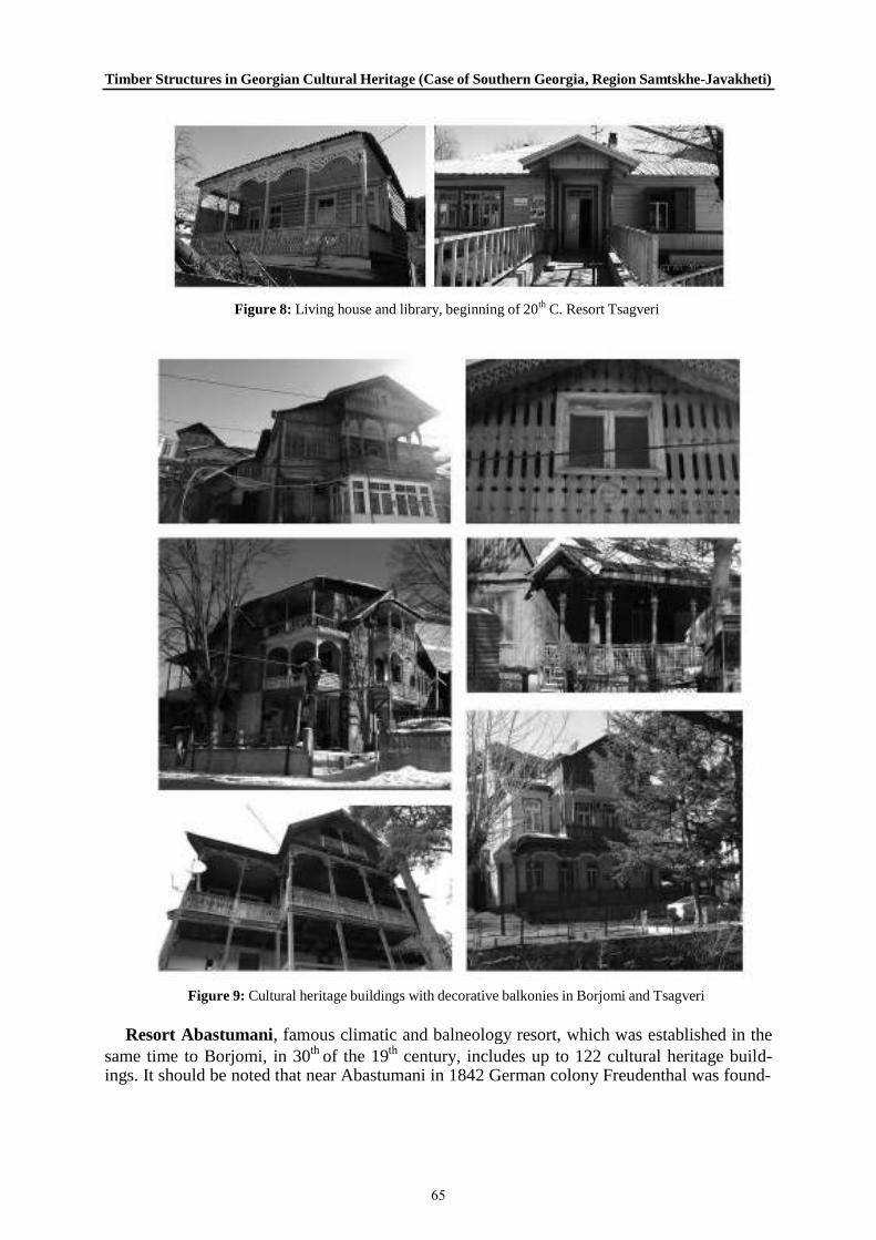
Timber Structures in Georgian Cultural Heritage (Case of Southern Georgia, Region Samtskhe-Javakheti)
Figure 8: Living house and library, beginning of 20th C. Resort Tsagveri
Figure 9: Cultural heritage buildings with decorative balkonies in Borjomi and Tsagveri
Resort Abastumani, famous climatic and balneology resort, which was established in the same time to Borjomi, in 30th of the 19th century, includes up to 122 cultural heritage build- ings. It should be noted that near Abastumani in 1842 German colony Freudenthal was found-
65

A. Tamar Khoshtaria, B. Nino Chachava and C. Malkhas Lekveishvili
ed [7]. Germans moved later in 1948 to Sartichala, but however, their traces could be felt in Abastumani. The church of Abastumani was planned by German architect Otto Simonson, under instruction of Russian prince George Romanov. Doctor Remmert, who worked for Rus- sian Kingdom for the development of both resorts – Borjomi and Abastumani, was burried in Abastumani.
Architecture of Abastumani is an excellent example of the positive eclectism, interesting synthesis of European, Georgian and Russian architecture. Heritage houses of Abastumani are rich on wooden timber details and are widely decorated with lace-style carvings.
Unfortunately, one of the outstanding buildings, comletely wooden palace of prince George, later named as sanatorium “Meskheti” was strongly damaged by fire in 2008. Only small part of the building survived. This and also other buildings suffered from many years of neglect.
Figure 10: Abastumani. Heritage Buildings with timber structures
Recently is planned to refurbish and restore the cultural heritage of Abastumani, Municipal Development Foundation of Georgia is preparing this project. Rehabilitation measurements
66
Timber Structures in Georgian Cultural Heritage (Case of Southern Georgia, Region Samtskhe-Javakheti)
should be done much earlier, in order to safe Abastumani’s rich potential. Many buildings are in such condition that refurbishment works are very difficult to implement.
Strategy for the Sustainable Develoment was elaborated for Abastumani, [8], but Borjomi is still in need for such solution. Urgent rehabilitation is necessary for the both resorts.
One of important factors for tourism is safety. Especially in the case of this region high seismic intencity (VIII point according the richter scale) is a fact. Timber constructions are very resistant against seismic hazard, and the log houses are one of the best examples in this case.
It should be noted that branding issue is very important for the development of resort cities and cultural heritage protection is one of the leading factors for the sucsessful result.
3 CONCLUSIONS
Sustainable development of tourism and recreation cluster of Samtskhe-Javakheti de- pends strongly on the cultural heritage protection. Resort cities are attractive for tourists and guests not only for beautiful landscapes and healing features, but for their exclusive appearance.
Numerous cultural heritage buildings are valuable due to their decorative timber details, which are sensitive. Long-term rehabilitation programs and high professional approach are necessary to implement for the protection of these monuments.
Timber constructions in living houses are resistant in seismic regions, and this tradition should be continued and improved.
REFERENCES
[1] About Samtskhe-Javakheti, Highlander travel, http://www.georgia- tours.eu/administrative-division/samtskhe-javakheti/, (2014), accessed 02.04.2017
[2] New life comes to Georgia’s 12th Century winemaking Tchatchkari Village.
http://agenda.ge/news/65190/eng (2016).
[3] Cultural heritage monument of national significance was given to the village chachkari, http://www.ipress.ge/new/52307-kulturuli-memkvidreobis-dzegls-sofel-chachkars-erovnuli- mnishvnelobis-kategoria-ganesazghvra, (2016), accessed in 31.03.2017
[4]. Sumbadze L., Wood carving in the folk Architecture, in Saunje, Dzeglis megobari, 1967, v.12, pp. 54-65 http://saunje.ge/index.php?id=1310&lang=ka
[5] Saro Houses Rehabilitation, http://mtisambebi.ge/news/people/item/293-saros-darbazis- tipis-saxlebis-reabilitazias-2-mln-300-atasi-lari-moxmardeba (2017)
[6] Materials of the Department of Culture of Borjomi Municipality and of Borjomi Local History Museum 2010-2012. In Georgian.
[7] Tatarashvili N., German Settlements and Architectural Heritage in Georgia, Architecture building bridges between people and times, Deutsch-Georgishes jahr 2017, Pp: 33-45.
[8] G.Gotsiridze, M.Tumanishvili, V.Vardosanidze, T.Khoshtaria, G. Abuladze, T. Bagdavadze, T. Papachashvili, M. Makhatadze, T. Bakuradze, L. Tumanishvili, Stepantsminda, Dusheti, Abastumani Development Strategy for Sustainable Development, Final Report, GIS & RS Consulting Center Geographic, 2015.
67

68

CHAPTER II
TRADITIONAL PRACTICES
69

70

PERSIAN WOODEN STRUCTURES: CHALLENGES IN REPAIR, STRENGTHENING AND RESTORATION
Mehrdad Hejazi1, Bina Hejazi2, and Saba Hejazi3
1Department of Civil Engineering, University of Isfahan, Isfahan, Iran, ISCARSHA/ICOMOS
2Institute of Material Testing, Department of Civil Engineering and Environment, University of Stuttgart, Stuttgart, Germany
3Department of Architecture and Urbanism, Art University of Isfahan, Isfahan, Iran
Abstract
This paper explains Persian wooden structures and challenges in their repair, strengthening and restoration.
Structural features include foundation, wall, roof and floors. Main causes of damage are ageing, moisture, air pollution, insects and fire. Traditional methods of structural strengthening have specific characteristics that protect the structures satisfactory.
Today’s methods of repair, strengthening and restoration of wooden buildings include traditional methods and modern ones. In some modern restoration methods irreversible and excessive interventions are implemented. The insect attack and fire are also major threats to wooden buildings.
Keywords: Persian, Wooden Structures, Restoration, Strengthening, Insect, Fire
71

Mehrdad Hejazi
1 INTRODUCTION
The use of wood as the building material in Iran has a long history which dates back to the first millennium. At that time wood was used to make the roofs, beams and columns of some buildings. The extensive use of wood in the construction of large wooden buildings came into practice in the seventeenth century A.D. In that era, huge wooden structures were constructed [1].
Structural features of Persian wooden structures, traditional methods of structural strength-ening, today’s methods of repair, strengthening and restoration, and other challenges in Persian wooden buildings are presented as follows.
2 STRUCTURAL FEATURES OF PERSIAN WOODEN STRUCTURES
2.1 Foundation
2.1.1 Sogti foundation A hole is excavated to reach the hard soil for construction of this type of foundation. A sogt
is a wooden round-section inserted in the hole. The hole is filled with rubble, on which a layer of clay soil is compacted (Figure 1). The sogt is tarred before installation in order to be protected against moisture [2-5].
Figure 1: Sogti foundation
2.1.2 Zogali foundation In moist ground, a zogali foundation is constructed, of which a part is outside the ground. A
hole with a section of 150 cm square is excavated in the ground. It is filled with lime concrete and is covered with a waterproof layer of compacted clay and duff. A number of logs with a diameter of 30 to 40 cm and a length of 100 cm are bonded by plant root or long nails and placed on the lime concrete foundation. The next sets of bonded logs are laid on the top and perpendicular to the previous set of logs to reach the required height (Figure 2).
2.2 Wall
2.2.1 Vargin wall This type of wall is the oldest method of constructing wooden walls in mountainous areas in
Northern Iran. Singular lime concrete foundations are construction under the junctions of walls.
72
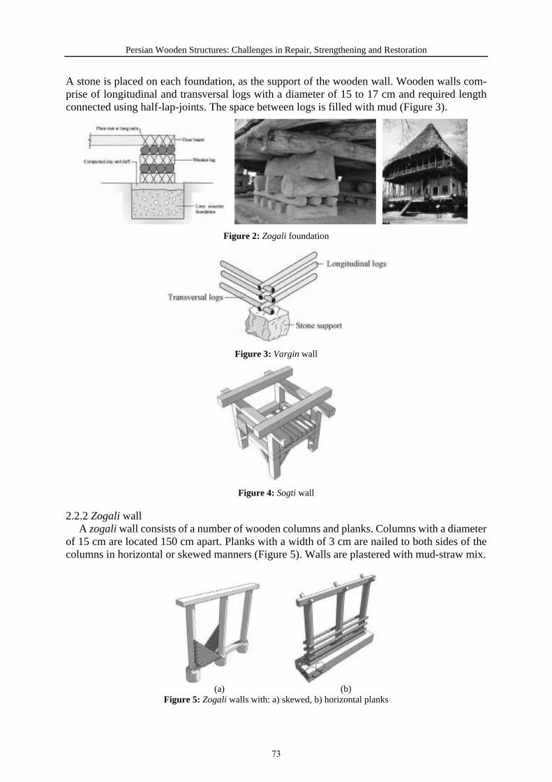
Persian Wooden Structures: Challenges in Repair, Strengthening and Restoration
A stone is placed on each foundation, as the support of the wooden wall. Wooden walls com-prise of longitudinal and transversal logs with a diameter of 15 to 17 cm and required length connected using half-lap-joints. The space between logs is filled with mud (Figure 3).
Figure 2: Zogali foundation
Figure 3: Vargin wall
Figure 4: Sogti wall
2.2.2 Zogali wall A zogali wall consists of a number of wooden columns and planks. Columns with a diameter
of 15 cm are located 150 cm apart. Planks with a width of 3 cm are nailed to both sides of the columns in horizontal or skewed manners (Figure 5). Walls are plastered with mud-straw mix.
(a) (b) Figure 5: Zogali walls with: a) skewed, b) horizontal planks
73

Mehrdad Hejazi
2.3 Roof
2.3.1 Galipush A wooden truss is the load bearing structure of the roof that transmits loads to the walls. It
is placed on a ring beam, which is in turn on the walls. Inclined members of the truss are con-nected by small branches. The truss is covered with reed or rice stems (Figure 6).
(a) (b)
(c) (d)
Figure 6: A galipush roof: (a) ring beam, (b) inclined elements of the truss, (c) small branches connecting the inclined members of the truss, (d) reed stems covering the truss
2.3.2 Latpush In this type of roof timber elements have a square cross-section and laths are used for final
covering of the roof (Figure 7).
Figure 7: A latpush roof: use of truss made of elements with a square cross-section, and laths for final covering
74
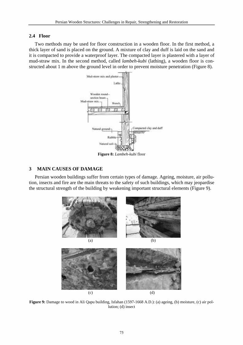
Persian Wooden Structures: Challenges in Repair, Strengthening and Restoration
2.4 Floor
Two methods may be used for floor construction in a wooden floor. In the first method, a thick layer of sand is placed on the ground. A mixture of clay and duff is laid on the sand and it is compacted to provide a waterproof layer. The compacted layer is plastered with a layer of mud-straw mix. In the second method, called lambeh-kubi (lathing), a wooden floor is con-structed about 1 m above the ground level in order to prevent moisture penetration (Figure 8).
Figure 8: Lambeh-kubi floor
3 MAIN CAUSES OF DAMAGE
Persian wooden buildings suffer from certain types of damage. Ageing, moisture, air pollu-tion, insects and fire are the main threats to the safety of such buildings, which may jeopardise the structural strength of the building by weakening important structural elements (Figure 9).
(a) (b)
(c) (d)
Figure 9: Damage to wood in Ali Qapu building, Isfahan (1597-1668 A.D.): (a) ageing, (b) moisture, (c) air pol-lution; (d) insect
75

Mehrdad Hejazi
4 TRADITIONAL METHODS OF STRUCTURAL STRENGTHENING
A number of measures are taken to improve the structural behaviour of wooden buildings; both against vertical loads and earthquakes. These measures can be categorised into actions for: 1) the foundation, 2) connections and 3) lateral elements. The actions may be implementedduring the construction of the structure or for strengthening after the structure has been dam-aged. Some measures are described as follows.
A stoneware pipe is inserted in the foundation for each wooden column. The diameter of the pipe is a few centimetres larger than that of the column. The lower part of the column is tarred and placed inside the pipe. The clearance of the column inside the pipe lets the column move during the earthquake and dissipates the earthquake energy (Figure 10). Zogali foundation is also capable of dissipate the energy of the earthquake transmitted from the ground to the build-ings (Figure 2).
Beam-column connections are constructed as a part of earthquake dissipating system so as to move and rotate. If the length of the groove in the beam is larger than that of at the top of the column, the beam can slightly move (Figure 11(a)). If the beam is connected to the column by strap and nail or bolt, with a clearance of 2 mm between the strap and the beam, the beam can rotate (Figure 11(b)).
Varjin, sogti and zogali walls are stiff enough to act as shear walls. The ring beam at the top of walls integrates the whole structure to resist earthquakes (Figures 3-5).
Figure 10: The clearance of the wooden column inside the pipe for dissipating the earthquake energy
(a) (b)
Figure 11: (a) Movement, (b) rotation of beam at its connection with column to dissipate earthquake energy
76
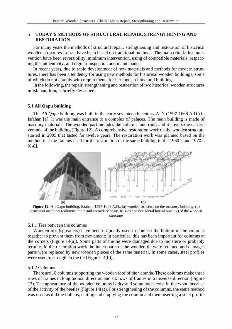
Persian Wooden Structures: Challenges in Repair, Strengthening and Restoration
5 TODAY’S METHODS OF STRUCTURAL REPAIR, STRENGTHENING AND RESTORATION
For many years the methods of structural repair, strengthening and restoration of historical wooden structures in Iran have been based on traditional methods. The main criteria for inter-vention have been reversibility, minimum intervention, using of compatible materials, respect-ing the authenticity, and regular inspection and maintenance.
In recent years, due to rapid development of new materials and methods for modern struc-tures, there has been a tendency for using new methods for historical wooden buildings, some of which do not comply with requirements for heritage architectural buildings.
In the following, the repair, strengthening and restoration of two historical wooden structures in Isfahan, Iran, is briefly described.
5.1 Ali Qapu building
The Ali Qapu building was built in the early seventeenth century A.D. (1597-1668 A.D.) in Isfahan [1]. It was the main entrance to a complex of palaces. The main building is made of masonry materials. The wooden part includes the columns and roof, and it covers the eastern veranda of the building (Figure 12). A comprehensive restoration work on the wooden structure started in 2005 that lasted for twelve years. The restoration work was planned based on the method that the Italians used for the restoration of the same building in the 1960’s and 1970’s [6-8].
(a) (b) Figure 12: Ali Qapu building, Isfahan, 1597-1668 A.D.: (a) wooden structure on the masonry building, (b)
structural members (columns, main and secondary beam, trusses and horizontal lateral bracing) of the wooden structure
5.1.1 Ties between the columns Wooden ties (spreaders) have been originally used to connect the bottom of the columns
together to prevent them from movement; in particular, this has been important for columns at the corners (Figure 14(a)). Some parts of the tie were damaged due to moisture or probably termite. In the restoration work the intact parts of the wooden tie were retained and damages parts were replaced by new wooden pieces of the same material. In some cases, steel profiles were used to strengthen the tie (Figure 14(b)).
5.1.2 Columns There are 18 columns supporting the wooden roof of the veranda. These columns make three
rows of frames in longitudinal direction and six rows of frames in transverse direction (Figure 13). The appearance of the wooden columns is dry and some holes exist in the wood because of the activity of the beetles (Figure 14(a)). For strengthening of the columns, the same method was used as did the Italians; cutting and emptying the column and then inserting a steel profile
77

Mehrdad Hejazi
(Figure 14(b)). It is interesting that despite the fact that it was assumed that the inside of the wooden columns were damaged by termites, there was no sign of termite and the wood was relatively intact.
(a) (b)Figure 13: Floor ties between the columns: (a) corner, (b) strengthened with steel profiles
(a) (b) Figure 14: Columns: (a) dry and insect holes, (b) strengthening by cutting and inserting steel profiles (irreversi-
ble and excessive intervention)
The connection of the columns to their base is originally simple using a tenon and mortise connection, capable of small rotation (Figures 15(a), (b)). During recent restoration a reinforced concrete foundation with a steel base plate on the top has been constructed under each column. Then the steel profile inside the column has been welded to the base plate making a rigid con-nection; hence, changing the simple connection to a rigid connection (Figure 15(c)).
The same has happened to the connection between the column and beam. Originally the beam has been connected to the lower column using a long iron nail making a simple connection to enable it to rotate (Figure 16(a)). During the restoration work the beam has been covered with a steel plate at the junction with the column and a rigid connection has been created be-tween the beam and the column (Figure 16(b)).
Unfortunately this method of strengthening of the columns and their connections is irreversi-ble and too much intervention is implemented; hence, the authenticity of the structure and its original structural behaviour is compromised.
78
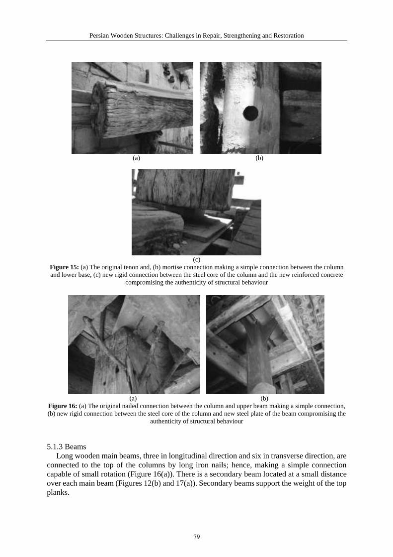
Persian Wooden Structures: Challenges in Repair, Strengthening and Restoration
(a) (b)
(c) Figure 15: (a) The original tenon and, (b) mortise connection making a simple connection between the column and lower base, (c) new rigid connection between the steel core of the column and the new reinforced concrete
compromising the authenticity of structural behaviour
(a) (b) Figure 16: (a) The original nailed connection between the column and upper beam making a simple connection, (b) new rigid connection between the steel core of the column and new steel plate of the beam compromising the
authenticity of structural behaviour
5.1.3 Beams Long wooden main beams, three in longitudinal direction and six in transverse direction, are
connected to the top of the columns by long iron nails; hence, making a simple connection capable of small rotation (Figure 16(a)). There is a secondary beam located at a small distance over each main beam (Figures 12(b) and 17(a)). Secondary beams support the weight of the top planks.
79

Mehrdad Hejazi
In recent restoration, a steel plate has been placed around the beam at its junction with the column and the original simple connection has been changed into a rigid connection between the steel core of the column and the steel plate around the wooden beam (Figure 16(b)). The structural behaviour of the new connection is completely different from the original simple connection that allowed rotation between the column and the beam.
In some parts, wooden beams have been strengthened with steel profiles (Figure 17(b)).
(a) (b) Figure 17: (a) Secondary beam over the main beam over the column with a steel cable lateral bracing attached to
the main beam, (b) a steel profile for strengthening the wooden beam
5.1.4 Lateral bracing The original lateral bracing of the wooden structure consists of a number of wooden elements
distributed horizontally around the roof inside the bays (Figure 12(b)). For the original structure with simple connections on both ends of the column and with no lateral resistance, the horizon-tal lateral bracing inside the roof was used to transfer the lateral load to the side thick wall.
In recent restoration, a number of steel cables have been added to the roof of the wooden structure in most of the bays (Figure 18). These steel cables seem to be too stiff compared to the wooden beams, to which they are connected. Hence, it is probable that they would damage the wooden beams in case of an earthquake. Additionally, as it was mentioned before, the sim-ple frames of the structure have been converted to rigid frames and as a result the lateral load will be distributed between the frames and the horizontal lateral bracing; hence, the authenticity of the original lateral load bearing system is fundamentally changed.
Figure 18: Wooden horizontal bracing system replaced by a steel cable bracing system that is too stiff
80
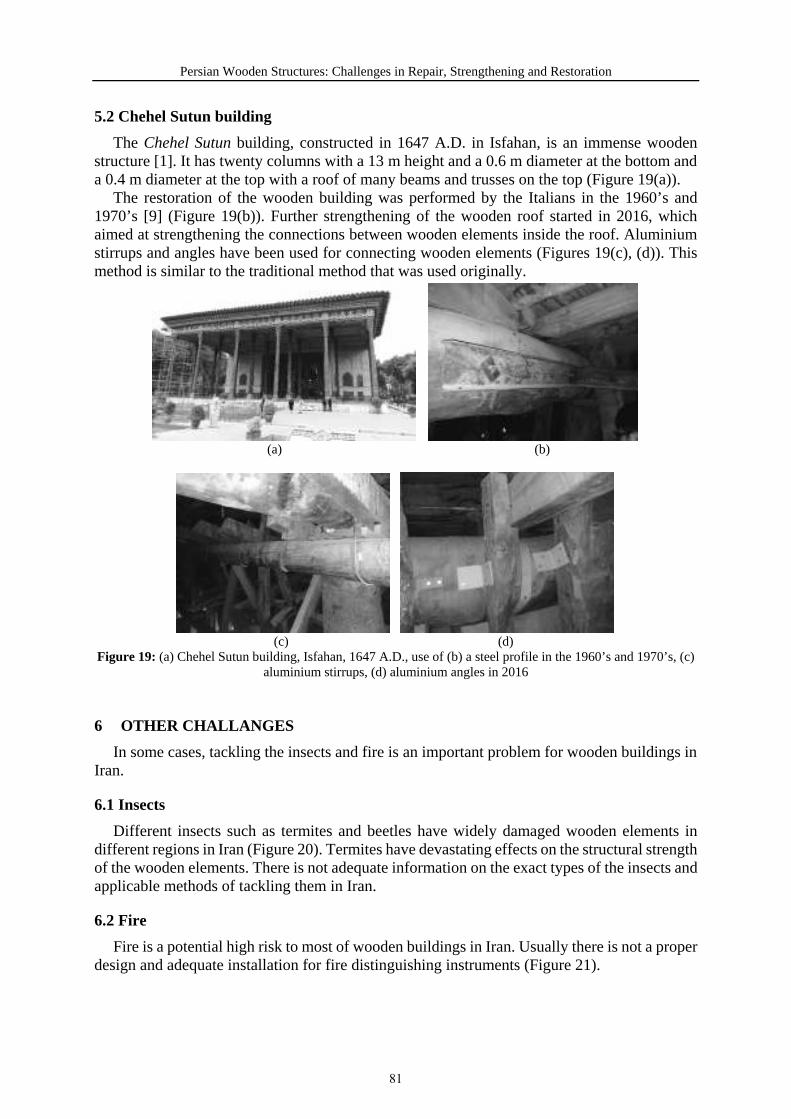
Persian Wooden Structures: Challenges in Repair, Strengthening and Restoration
5.2 Chehel Sutun building
The Chehel Sutun building, constructed in 1647 A.D. in Isfahan, is an immense wooden structure [1]. It has twenty columns with a 13 m height and a 0.6 m diameter at the bottom and a 0.4 m diameter at the top with a roof of many beams and trusses on the top (Figure 19(a)).
The restoration of the wooden building was performed by the Italians in the 1960’s and 1970’s [9] (Figure 19(b)). Further strengthening of the wooden roof started in 2016, which aimed at strengthening the connections between wooden elements inside the roof. Aluminium stirrups and angles have been used for connecting wooden elements (Figures 19(c), (d)). This method is similar to the traditional method that was used originally.
(a) (b)
(c) (d) Figure 19: (a) Chehel Sutun building, Isfahan, 1647 A.D., use of (b) a steel profile in the 1960’s and 1970’s, (c)
aluminium stirrups, (d) aluminium angles in 2016
6 OTHER CHALLANGES
In some cases, tackling the insects and fire is an important problem for wooden buildings in Iran.
6.1 Insects
Different insects such as termites and beetles have widely damaged wooden elements in different regions in Iran (Figure 20). Termites have devastating effects on the structural strength of the wooden elements. There is not adequate information on the exact types of the insects and applicable methods of tackling them in Iran.
6.2 Fire
Fire is a potential high risk to most of wooden buildings in Iran. Usually there is not a proper design and adequate installation for fire distinguishing instruments (Figure 21).
81
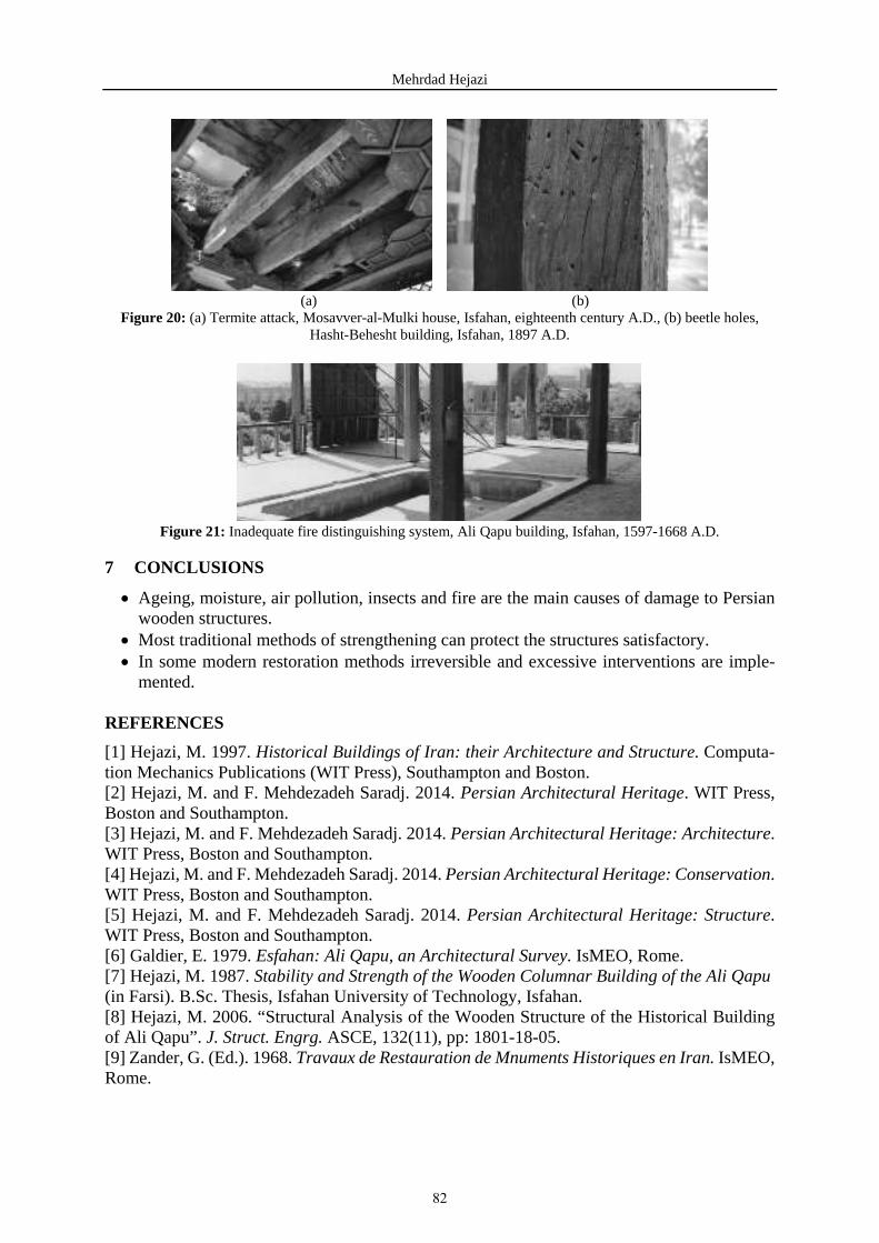
Mehrdad Hejazi
(a) (b) Figure 20: (a) Termite attack, Mosavver-al-Mulki house, Isfahan, eighteenth century A.D., (b) beetle holes,
Hasht-Behesht building, Isfahan, 1897 A.D.
Figure 21: Inadequate fire distinguishing system, Ali Qapu building, Isfahan, 1597-1668 A.D.
7 CONCLUSIONS
Ageing, moisture, air pollution, insects and fire are the main causes of damage to Persian wooden structures.
Most traditional methods of strengthening can protect the structures satisfactory. In some modern restoration methods irreversible and excessive interventions are imple-mented.
REFERENCES
[1] Hejazi, M. 1997. Historical Buildings of Iran: their Architecture and Structure. Computa-tion Mechanics Publications (WIT Press), Southampton and Boston. [2] Hejazi, M. and F. Mehdezadeh Saradj. 2014. Persian Architectural Heritage. WIT Press, Boston and Southampton. [3] Hejazi, M. and F. Mehdezadeh Saradj. 2014. Persian Architectural Heritage: Architecture. WIT Press, Boston and Southampton. [4] Hejazi, M. and F. Mehdezadeh Saradj. 2014. Persian Architectural Heritage: Conservation. WIT Press, Boston and Southampton. [5] Hejazi, M. and F. Mehdezadeh Saradj. 2014. Persian Architectural Heritage: Structure. WIT Press, Boston and Southampton. [6] Galdier, E. 1979. Esfahan: Ali Qapu, an Architectural Survey. IsMEO, Rome. [7] Hejazi, M. 1987. Stability and Strength of the Wooden Columnar Building of the Ali Qapu (in Farsi). B.Sc. Thesis, Isfahan University of Technology, Isfahan. [8] Hejazi, M. 2006. “Structural Analysis of the Wooden Structure of the Historical Building of Ali Qapu”. J. Struct. Engrg. ASCE, 132(11), pp: 1801-18-05. [9] Zander, G. (Ed.). 1968. Travaux de Restauration de Mnuments Historiques en Iran. IsMEO, Rome.
82
THE OTTOMAN HOUSE / EVALUATION OF STRUCTURE AND FORM
İbrahim Canbulat
Master of Architecture
Keywords: Ottoman House, Ottoman Architecture, Timber Structure, Wooden Frame, Wooden House
Abstract
Even if in limited number of samples of Ottoman houses remained, the written sources from the Ottoman period that we accessed show how the Ottoman state power kept a tight grip on the city and its structures, so that the construction practice defined as vernacular architecture was scientifically and technologically managed and supervised from the 16th century onwards at the latest. The newly emerging socioeconomic requirements of those eras led to an important stage in the development of the Ottoman house. While declaring that the Ottoman house had reached its magnificent peak in 19th century, we were also witnessing the collapse of the wooden Otto-man house in the meantime.
Several Ottoman houses that are within the framework of our study today are facing significant structural problems. I do not know how such problems are being solved during the restoration processes. In this presentation, I will be using the archaeological research findings to discuss how the wooden frame emerged, how timber elements were standardized by the Supreme Porte orders, how this shaped the Ottoman house, how it not only shaped it but also successfully developed an urban fabric that was earthquake resistant, and how the building dimensions were this time clearly identified through the Building Codes that was enforced around the end of the 18th century.
Ottoman Houses started emerging on the building technologies of ancient Anatolia developed in the past 8 – 10.000 years. Archeological surveys show the initiation of wooden frames in Neolithic Period. Not in an uninterrupted line but consequential findings and records are evi-dences of the survival of wooden frame in all consecutive periods. Constantinople / Istanbul became a stage for the rebirth of the wooden houses in 16. Century after a devastating earth-quake. The efficiency and flexibility of wooden frame were fully utilized by Ottomans to create a very impressive civil architecture. Unfortunately, wooden skeleton evolved but could not sur-vive after 19. Century and lost competition to masonry and later to reinforced concrete.
83

İbrahim Canbulat
1. INTRODUCTION
It appears that the frame used in Ottoman houses developed because of a technological evo-lution that dates to ancient times. When we carefully examine the archaeological findings, writ-ten resources and finally the Ottoman houses that have survived into the present, we are able to determine its development. I am talking about a process of no less than approximately 8,000-10,000 years. Local construction technologies first and foremost use local materials, and de-velop techniques that will fulfill their requirements. The vernacular structure especially evolves through processes of trial and error. However, earthquakes prove the biggest test for structural systems.
Even if in scant supply, the written resources from the Ottoman period that we accessed show how the Ottoman state power kept a tight grip on the city and its structures, [1] so that the construction practice defined as “architect-less architecture” (vernacular) was scientifically and
technologically managed and supervised from the 16th century onwards at the latest. [2] The
timber structure supply that emerged during the period when the Ottoman state power was man-aging the area of construction ultimately reached perfection in its resilience against earth-quakes.
Almost all the Ottoman houses in Anatolia that have survived until today date back to the
19th century. There are only about 10 of these timber mansions dating back to the 18th century,
and the historical value of almost all of them has been lost due to incorrect restoration. It is very sad that research studies on Ottoman houses can only be conducted on a very limited number of examples that remain. [3] Even though restoration activities continue at full steam today, research studies on Ottoman houses have fallen off the academic agenda. The studies that
Figure 1: Müderrisler Evi (House of the Professors) Safranbolu, 1786-7 (Photo by the Author)
84

Ottoman House / Evaluation of Structure and Form
started during the mid 20th century have been unable to expand outside of the areas of art his-tory and architectural history, which are generally based on documentation and determination of origin and typology. [4] Due to the restoration works that have been gradually picking up speed in the last 20 years, we need to bring about an in-depth vision to the Ottoman house urgently. We cannot de ne a restoration activity only within the context of the accurate imple-mentation of ICOMOS rules. Preliminary works that are performed for restoration projects to-day are limited to surveys, wear and decay reports, and at most, to some material analyses. Basically, in the long run, traditional structure and construction technologies become the basis for restoration works. I am sorry to say that most architects who have been involved in restora-tion works have had insufficient knowledge in this area.
For almost 20 years I have been deeply interested in the restoration of wooden structures. Over this time, I realized that some structural mistakes had been frequently repeated on the constructions I was working on. Settlement and collapse due to a mismatch of [5] structural solutions in different stories are the most common mistakes that I have observed. As I started to inquire about their probable causes, I discovered that these issues emerged in the 19th century [6]. The newly emerging requirements of that century led to an important stage in the develop-ment of the Ottoman house. While declaring that the Ottoman house had reached its magnificent peak in that century, we were also witnessing the collapse of the wooden Ottoman house in the meantime. Having reached perfection as the result of thousands of years of trial and error, the Ottoman houses using wooden frame systems unfortunately failed to meet the new necessities of the 19th century. Several Ottoman houses that are within the framework of our study today are facing significant structural problems. I do not know how such problems are being solved during the restoration processes. But I’m afraid to say that the structural engineers with whom we cooperate in the field of restoration, which is an interdisciplinary domain, do not have suf-ficient experience in this area.
In this presentation, I will be using the archaeological research findings to discuss how the frame system emerged, how timber elements were standardized by the Divan-ı Hümayun (Ot-toman Supreme Court) decrees, how this shaped the Ottoman house, how it not only shaped it but also successfully developed an urban construction stock that was earthquake resistant, and how the structural dimensions were this time clearly identified through the Ebniye Nizamnamel-eri (Building Codes) that was enforced around the end of the 18th century. It would be wrong to discuss this without mentioning the social-economic environment of the Ottomans. Finally, I will share my arguments regarding how the architectonics of the Ottoman houses that emerged over a zone that stretched from Anatolia to the Balkans formed under the influences (impacts) I listed above.
2. DEVELOPMENT OF WOODEN FRAME
Established around camp huts made from tree branches were initially being used in the Paleolithic Period (10,000 BC), [7] and after a while people started plastering them with clay. In the Pre-Pottery Neolithic Period (8200-6000 BC) “with a floor that was raised on a founda-tion with a cellular layout, to be covered by wattle and a layer of clay plaster.” [8] At Höyücek Barrow in the Turkish Lake District, which was dated back to 7600/7511-7387/7311 BC, “thin screens in the form of wattle plastered with clay” were found. [9] The relationship between timber and earth can also be seen in the İkiztepe Settlement dating back to the Late Chalcolithic Early Bronze Periods (5000-3000 BC). Traces of branches and leaves can clearly be seen on the clay pieces that were found at the excavation site and appear to have ceramification in a fire. [10]
85

İbrahim Canbulat
The most comprehensive examples of early wooden frame houses are coming out from the Ilıpınar Settlement (Figure 2) which is on the western shore of İznik Lake and excavated by Jacob Roodenberg of The Netherlands Institute for the Near East, Leiden. Ilıpınar Settlement is dated to 6000-5400 BC., Neolithic and should be a small village of early farmers. Normally, wooden structural elements cannot be found after that much of long time due to woods perish in nature. After excavation and examining of 7 m deep layered archaeological fill, not only the holes of the wooden poles were discovered, but also fossilized wood itself as poles, beams and planks. The Ilıpınar houses were in three kinds which can be itemized as Post-Wall, Mud-Slab and Mud-Brick. Post-Wall system is closely related to wooden frame whereby the posts were placed in 50cm deep pits and were infilled with pisé blocks about 25-30 cm sizes. There wasn’t any wattle or lathe application on posts. It is assumed that these houses were used in planting and harvesting seasons but not in winter due to their low insulating capability. These houses were used in the first half of the period for 300 years together with Mud-Slab houses. Then they were abandoned in Holocene Period most probably due to climatic changes, but once more appeared about 2,000 years later in Early Bronze Age at Hacılartepe. [11]
Many years later and for the first time we come across a timber framing system in a written source. [12] Having lived in the 1st century BC, Vitruvius had drastically negative opinions on lath and plaster. He says, “... given the fact that it is at times necessary to use it to save money or for partitions in unsupported gaps, the correct method of construction is explained below”, and then points at the masonry walling techniques that he explained before, providing an elab-orate description of various types of timber and their preparation processes. We cannot find any other detail regarding frames in this resource. However, I cannot help but agree with Vitruvius on lath and plaster. At the Elçi Han (Ambassadors’ Inn) where Dernschwam stayed when he visited Istanbul in the 16th century, the sections of rooms were also constructed with lath and plaster applied on frames. [13] What is interesting is that Vitruvius’ lath and plaster application, which was used as a partition in unsupported areas (those with structural problems), will appear again in the 19th century Istanbul houses in quite an active way. On the engraving featured in Schweigger’s book that shows two 16th century two-storey Istanbul houses with one ground floor, we finally see a structure that has both stone fillings and cruciform frames. [14] Therefore, we should consider that between the 1st and 16th century somewhere in the Mediterranean basin and over a long period of time timber cruciform frames were being put into practice as a solution to improve the durability of structures against earthquakes. My research studies have been de-veloping in a way which shows that wooden frame structures emerged in 16th century Anatolia.
Figure 2: Il ıpınar Excavation and Ilıpınar Post-Wall House (Roodenberg, Jacob 1999)
86
Ottoman House / Evaluation of Structure and Form
3. WOODEN FRAME
There are many published studies [15] on the frame that was used in the Ottoman house. However, they have been unable to go beyond the frameworks that were used in the second dimension (planar) and in the facade. [16] What I will try to examine thoroughly in this presen-tation is the necessity to analyze the frame as a three-dimensional system under dynamic and static loads.
I believe that in the 16th century, wooden framing had survived at the periphery of the Otto-man Empire. It became widespread in the 16th century when it was deliberately brought to Is-tanbul, and perhaps it was made a mandatory practice to observe. As I will mention in the following paragraphs, this period overlaps with the aftermath of the September 10, 1509 earth-quake, known as the Kıyamet-I Suğra (Little Apocalypse), and from this point of view, the real objective would have been to prioritize a structural style that was earthquake-resistant. Other-wise, Istanbul is not located in a fertile geography in terms of forest products. [17] Therefore, it is not an appropriate practice for the definition of local architecture, which employs local materials. In that sense, in the early 16th century it shouldn’t be considered odd that most the buildings in Istanbul were masonry. As a matter of fact, Istanbul always had to import from afar to meet its timber needs. However, the fact that framing is quite easy and fast to install must have been considered a good solution in Istanbul. [18]
There are two records from the documents of the Divan-ı Hümayun that standardized the dimensions of the timber that was to be brought to Istanbul. [19] These two documents start by saying the following, “It has been mandated to the Istanbul judge and to the chief architect that the timber they have cut and brought to Istanbul for some important buildings are not cut ac-cording to the customs, they are cut too short, and since it is decided that this does not bene t the practice and damages the building, as it was cut since the old times”. This shows that the Ottoman State power was striving to supervise not only the quality of the timber that was to be used in Istanbul, but also most of the construction site over the matter of timber.
4. “ON THE VARIETY OF TIMBERS TO BE USED IN ISTANBUL”
We see in two documents from the Ottoman Supreme Court archive that the dimensions of the timber to be used in Istanbul were very elaborately described. So much so that the timber construction elements which have been identified echo a Meccano toy set. [20] Almost every item was individually named, and their widths, lengths and heights were set out. Some were specified by their origins, while others were identified by the species of tree. The list dated May 19, 1568 defines 20 different elements, while 14 years later, the list that was finalized in March 6, 1582 indicates 54 new elements. I believe that the second list added new timber construction elements compared to the first list. Even though it is possible to form a view on what some could have been like based on their dimensions, the resources show no records of the others.
I classify the structural timber construction elements that were on the list in 2 sections: The first list shows a beam with the same cross-section (7x5 inch), but in two different lengths (12 and 15 zira). I believe it is beneficial to first examine the cross-section. My experiences have shown that joists in old structures are carved with a single log axe. This method ensures both the static symmetry of the timber, and the maximum use of hard wood at the center of the cross-section, while it enables the timber element to reach its highest breaking resistance. What is more, the cross-sectional dimensions for the highest breaking resistance of a joist that will be obtained for a single log (or its maximum section modulus) is at the rate of 1 / √2, which are its optimum dimensions. [21] This makes 1 / 1.41 and 5 / 7 inch gives a very similar value to this. This detail just in itself points at a very significant knowledge of engineering behind this list. Two new cross-sections (12 and 8-inch-deep) were added to the second list, but their widths were not indicated. At this point, I argue that the person or people who prepared the list must
87

İbrahim Canbulat
have assumed that the 1 / √2 ratio would be widely used for widths. According to this, the cross-sections would be 12x8.5* and 8x5.7* inches.
Another group of joists on the list are the “Joists to be constructed on tolma posts”. There is only one cross-section given for this group. This is around 6x4.2* inches for the optimum cross-section I described above, and it indicates joists with a cross-section of 19x13*cm. The distance between these joists to be placed underneath the floor, and spread over the walls or on the verdinar bases, may be changed based on the load they carry and the moment length. I have determined the average distance between the joists in the houses of Safranbolu as being 52 cm. Eldem, determines this distance between joists to be 40 cm. I must specify that the houses which Eldem provides as examples are structures from the 18th -19th century. In Eldem, it is indicated that the joist gaps vary from 40-70cm and that both the gaps and joist cross-sections in the older houses are larger. [22] Arseven, states that the floors were terracotta. [23] This indicates an unusual dead load that is more than the weight of the timber joists. The thickness of the wood on the list that may be used as flooring is 1 or 1.5 inches (3 and 4.5 cm). And this indicates very low dead loads. As it can be seen, having only one joist cross-section on the list is not a very limited specification. It is obvious that the gaps between joists were determined in accordance with the experiences of the master carpenter. Whether used on the fir joists or the wall framing posts, the lengths of the joists were indicated as 8, 10, 12, 14 and 16 zira. These correspond to 6.06, 7.58, 9.09, 10.61 and 12.12 meters in the metric system. Here again we see floor joists with lengths that exceed the dimensions of the rooms. I will discuss the reasons why in the following sections.
The fact that the list was elaborately prepared, and more importantly, that it is technically perfect within the context of the static I pointed out above, makes it seem that the list was prepared by the Hassa Mimarları (Imperial Corps of Archi-tects), and it was submitted to the Palace to be made a Supreme Court Decree. [24]
5. TOWARDS THE OTTOMAN HOUSE
Bursa’s Sarayönü District house (Figure 3), a drawing and a description of which can be found in Eldem, is the oldest Ottoman house I could find in the literature. [25] Eldem describes this house as “possibly dating back to the oldest and earliest period.” The reason it is important for me is the fact that it dates to the same century when the Supreme Court issued the decrees regu-lating the timber dimensions that were mandated to be used in Istanbul. There is no documented house in Istanbul that dates to the 16th century and has survived until today. My goal was to conduct a static analysis of the Sarayönü House, the survey of which exists, along with the identified timbers, and study the structural dimensions from that per-spective. The house whose drawing you see is comprised of a ground floor and one upper floor. It is surrounded on three sides by a stone wall that I estimate as being 1 zira wide. The house was car-ried by a frame that was bearing on the stone wall.
Figure 3. Bursa, Sarayönü House, (Eldem 1984, V.
I, Pp: 50)
88
Ottoman House / Evaluation of Structure and Form
While it is understood to be in a garden, it is generally different to the typical houses of that period with courtyards where the garden and the exterior door open to the indoors of the build-ing. In both floors, there are courtyards [26] that become integrated with the garden, and the rooms (and the barn on the ground floor?) can be accessed from the courtyard. While the struc-ture has windows that directly open to the outside, the windows and top windows, as seen in most of the houses in that period, open to the courtyard. The ground floor plan of the structure is not provided; on both floors, there are posts on the side of the courtyard that faces the garden. The ground layer of the wall that goes across the structure must be made of stone; the upper layer seems to be a cabinet (frame plus brick in filling).
The drawing shows that the posts on the courtyard front facing the garden are approximately 3 zira long. and 4 zira long on the upper floor, and that they have sections of approximately 6x6 inches. The most interesting aspect of this is that the beam between the posts and which crosses the courtyard (from outside to outside) is 16 zira long, whereas the floor joists that were put on top are 12 zira long (from outside to outside in total). The lengths of both bases are the longest dimensions stated on the lists. I have found that the gaps between the posts are 3 zira long. I assume that the joists used under the flooring are 7x5 inches, and that the main joist is 8x5.7* inches. The critical gap in the floor joists occur in the wider section which is under the rooms, and this gap seems to be 6 zira from the drawing. The width of the courtyard is calcu-lated as 4 zira. [27] I will try to summarize below the gaps that I have calculated and the (stand-ard) cross-sections that I selected from the timber list, as well as the static analysis I have conducted regarding the timber structure. The size of the movable load, for which I will conduct a static analysis, is still not certain. There is no furniture in Ottoman houses. Therefore, the first thing that comes to mind is that it should be light movable loads. However, I see that this is not an accurate assumption. Unfortunately, due to limited space, I cannot go through the calcula-tions here. At this point, I attribute the fact that the joists to be used in Istanbul had redundantly long and large cross-sections to three causes: � We encounter a lower critical moment in the continuous joist option, and the joists defect
less under a dead load, while under a movable load they prevent excessive spring back. � Joists go beyond the whole structure from end to end and function as joiner beams. geome-
try is obtained by the triangles that are created. Cantilevers too under the projections also provide stability.
� While choosing the cross-sections of the joists (and the post), the risk of fire must absolutelybe taken into consideration.
Consequently, the effects of the 1509 earthquake and the fires that ravaged Istanbul lead the Supreme Court Decree to try to define a new Ottoman house structure. The oldest Ottoman House, the drawings and photographs of which I have been able to find, located in Bursa’s Sarayönü Neighborhood, appears to have been built with exactly those standard timbers bought from the market. From this point of view, perhaps the house with the above-mentioned plan was a typical house that was developed and commonly used in the Ottoman periphery (without neglecting the fact that Bursa was the first capital of the Ottomans). At this point, I can com-fortably claim that a typical house in Istanbul was brought from outside and that, according to the results of the static analyses I explained above, there is significant technological knowledge behind the list.
6. EBNİYE NİZAMNAMELERİ During the 19th century and later, the structural stock of Istanbul started to turn to masonry,
especially due to fires. By the time we get to 1918, the only neighborhoods within Istanbul’s city walls with a great amount of timber houses were Zeyrek, Süleymaniye, Soğuk Çeşme and Küçük Ayasofya, -partially- because of the fires. [28] The state power had made a significant
89

İbrahim Canbulat
number of decisions regarding fire intervention and fire prevention, and tightly supervised their implementation. Decrees and charters regarding the restriction of building heights and expan-sion of streets were all enforced with that purpose in mind. We will go back to this topic later.
However, because of encouraging masonry construction in Istanbul, the structure stock in Istanbul would rapidly become masonry. The orders and regulations that are found in Serim Denel’s book called Batılılaşma Sürecinde İstanbul’da Tasarım ve Dış Mekanda Değişim ve Nedenleri, [29] which are directly related to our topic, were enforced almost always by taking Istanbul into consideration as a city where there was the risk of fire. While some of them are directly for fire prevention, those that bring forth rules on building heights, street widths, and similar dimensions, are eventually written with the purpose of preventing the expansion of fire or easing fire intervention. An important group of commands and regulations are full of sanc-tions that almost complicate the transition to a masonry structure. [30]
D’Ohsson writes the building heights were carefully supervised to reduce the risk of fireand to enable fire intervention. [31] Sanz says that Sinan Pasha used to walk atnight incognito [32] “... to find out whetherthe city was taking the necessary precautions against fires. Since there were verysmall timber houses in Istanbul, it wouldbe very hard to save them during a fire.” It is only natural that there had been various coercive directives published in this matter.
The restrictions regarding the building heights that were enforced with the Building Codes inevitably affected the heights of the floors. According to the Building Codes dating back to H1137 it is understood that non-Muslims had already not been able to build more than two stories. As for the Muslims, the way to fit into a total 9m height had been to make the mezza-nines low. While all resources indicate that mezzanines hosted services and therefore were made low, the measurement that was enforced for the whole structure was initially applied to the upper floor and inevitably to the ground floor [33], while balance was set aside for the mezzanine. While it was not written clearly before H1137 (1717). I do believe that there had been a floor height restriction. Indeed, there was some sort of regulation regarding the lengths of the studs that would enter Istanbul.
Even though the state power had wanted the new residences to be masonry with the assump-tion that it would be hard to burn, it had not been successful in this matter. As a precaution, the regulation dated H1131 “... orders the demolition of small timber houses that have been built instead of large residences, such as palaces and mansions that make it harder for the fire to spread with their wide courtyards, so that they won’t fill in the vacant lots.” [34] The interesting point here is that this is a documentation of the previously gentrified Istanbul going back to simple structures. Apparently when it comes to the 17th century, the socio- economic structure of Istanbul had been going through some changes. It is striking to see that the development had gone in a different direction compared to the periphery. According to Kuban there are several lost palaces, the locations of which are lost to us now. [35]
When the 1848-1849 Building Codes were accepted, the issue of emphasizing masonry ra-ther than timber was repeated, as it was highly encouraged in the past. Furthermore, the char-acteristics and form of construction of the stones, timber and mortar material that were to be used were determined in detail. The content of almost all provisions were considered a fire prevention. Paragraph II of Regulation 1 dating back to Evail H1264 (1848) says “Those who build houses and shops in wooden construction will make masonry wall up to the altitude of two zira (1,52 m), and if they cannot afford they must make among the ten houses and the shops
. Later, it was known that the practice of stone fire walls built between every five house had spread after the middle of the last century.” Also, “So much so that, a document dating back to
90
Ottoman House / Evaluation of Structure and Form
7 Rebiyülevvel H1175 (1762), determines the conditions of materials and construction and in-dicates that: ‘... and the stone masons and merchants that attempt to apply the structural re-strictions will be hanged as a warning to others”. [36]
7. CONCLUSION
Ottoman Houses started emerging on the building technologies of ancient Anatolia devel-oped in the past 8 – 10.000 years. Archeological surveys show the initiation of wooden frames in Neolithic Period. Not in an uninterrupted line but consequential findings and records are evidences of the survival of wooden frame in all consecutive periods. Constantinople / Istanbul became a stage for the rebirth of the wooden houses in 16. Century after a devastating earth-quake. The efficiency and flexibility of wooden frame were fully utilized by Ottomans to create a very impressive civil architecture. Unfortunately, wooden skeleton evolved but could not sur-vive after 19. Century and lost competition to masonry and later to reinforced concrete.
It appears that after the great earthquakeof 1509, all houses were rapidly replacedwith timber structures within 50 years and therefore the 1879 earthquake was dodgedwith very little losses, but now we have ignored the experiences learned in the daysof the Ottoman Empire, once again leaving Istanbul at risk when another earthquakehits. I attach importance to the evolution of the Ottoman house from two aspects. Especially in Northern Anatolia there is a high risk of earthquakes. The frame thatwas used in the Ottoman house could still have been used, however it is completely forgotten now. While timber is successfully being used for houses in several countries, it is considered almost improper even to suggest it in Turkey. The second important issue is the application of the principles of a frame system to modern building designs considering the durability of this system against earthquakes. There is a group of sci-entists, although very few, who are working on this subject both in our country, and around the world. As I mentioned in the introduction, restoration processes are being conducted without an in-depth knowledge on the Ottoman house structure and the engineers who are involved in them are suggesting exaggerated solutions. The solutions they suggest and have applied every now and then are comprised of small pieces and reduce the flexible frame into a reinforced concrete and steel carcass, encouraging rigidity. This may create unwanted consequences, such as the accumulation of shocks and making them even more destructive, rather than stretching the jolts during an earthquake. The last paragraph deserves its own individual essays.
91
İbrahim Canbulat
REFERENCES
[1] Although control and auditing of the construction sphere seem only in the capital cities, the experiences used to be carried to provinces and even to the villages by the builders. [2] At this point, the Greek - Roman - Byzantine continuity should not be neglected. [3] However, various books by Eldem, S. H. 1984, 1986, 1987. Türk Evi / Osmanlı Dönemi, 3 volumes, T.A.Ç., İstanbul and Arseven, C. E. 1956. Türk Sanatı Tarihi / Menşeinden Bugüne Kadar Mimari, Heykel, Resim, Süsleme ve Tezyini Sanatlar. Milli Eğitim Basımevi, İstanbul, V. 3 (Architecture) include a limited number of house surveys that they dated retroactively back to the 16th century. [4] Arseven 1956; Aksoy, E. 1963 “Orta Mekân: Türk Sivil Mimarisinde Temel Kuruluş Pren-sibi” Mimarlık ve Sanat, İstanbul, Nr. 7-8, Pp: 39-92; Goodwin, G. 1971. A History of Ottoman Architecture, Thame & Hudson, London; Arel, A. 1982. Osmanlı Konut Geleneğinde Tarihsel Sorunlar. EÜ, Güzel Sanatlar Fakültesi, İzmir; Eldem 1984; Kuban, D. 1995. The Turkish Ha-yat House. Eren, İstanbul; Küçükerman, Ö. & Ş. Güner 1995. Anadolu Mirasında Türk Evleri. T.C. Kültür Bakanlığı, Ankara; Altıner, Ahmet Turan & Budak, Cüneyt 1997. The Konak Book. A Tepe Publication, İstanbul; Sözen, Metin 2001. Türklerde Ev Kültürü, Doğan Kitapçılık, İs-tanbul; Yürekli, H. & F. Yürekli 2005. Türk Evi / Gözlemler Yorumlar, Yapı Yayın, İstanbul; Bektaş, Cengiz. 2007. Türk Evi, Bilişim, İstanbul; Tanyeli, Uğur “Anadolu’da Bizans, Osmanlı Öncesi ve Osmanlı Dönemlerinde Yerleşme ve Barınma Düzeni”, Edited by Yıldız Sey, Tarih-ten Günümüze Anadolu’da Konut ve Yerleşme. Tarih Vakfı, İstanbul, Pp: 405–471, followed a different route than others as he could address important questions regarding the Ottoman house using first-hand resources and construction materials such as wood, glass, etc. [5] Arel 1982, Pp: 36 and Akın, Nur 2001. Balkanlarda Osmanlı Dönemi Konutları, Literatür, İstanbul, Pp: 270 are both aware of this problem, however they do not elaborate as to its causes. [6] Based on the dendrochronology analyses conducted at the IU, Faculty of Forestry. [7] Acar, E. “Anadolu’da Tarihöncesi Çağlardan Tunç Çağı Sonuna Kadar Konut ve Yer-leşme”, Tarihten Günümüze Anadolu’da Konut ve Yerleşme, Edited by Y. Sey, Tarih Vakfı, İstanbul, Pp: 381, f. 4. [8] Acar, Pp: 383, f. 8. [9] Duru, R. “Göller Bölgesi’nde Neolitik Köyden Kasabaya Geçiş” Der. Y. Sey, Tarihten Gü-nümüze Anadolu’da Konut ve Yerleşme, Tarih Vakfı, İstanbul, Pp: 51 and Özdoğan, Mehmet ve Nezih Baş gelen 1999 Neolithic in Turkey / the Cradle of Civilization, 2 Volumes: Text & Plates, Arkeoloji ve Sanat Yayınları, İstanbul. Pp: 7, f. 7. [10] Dönmez, Ş. ve E. Naza-Dönmez 2005 “Aspects of Traditional Village Architecture in the Central Black Sea Region” Ethno-archaeological Investigations in Rural Anatolia, Volume 2, Ed. T. Tahaoğlu, Ege Yayınları, İstanbul, Pp: 165, f. 5. [11] Roodenberg, Jacob 1999 “Ilıpınar, an Early Farming Village in the İznik Lake Basin” Neolithic in Turkey / the Cradle of Civilization, Text & Plates, Edited by Mehmet Özdoğan & Nezih Başgelen, Arkeoloji ve Sanat Yayınları, Pp: Text: 193-; and also: Roodenberg, Jacob. “Change in food production and its impact on an early 6th millennium communityin north-west Anatolia. The example of Ilıpınar”. Paraehristorische Zeitschrift, 2012; 87(2), Pp. 223-235. Mr. Roodenberg was very kind to edit my wordings and quoted by his e-mail dated June 21, 2017 that “The early post-wall structures found at Ilıpınar are repeated many centuries of the Neolithic period throughout eastern and even central Europe. For instance, in Bulgaria similar ground plans of Neolithic houses have been excavated.”
92

Title of the Paper
[12] Vitrivius 1998 Mimarlık Üzerine On Kitap. Albert A. Howard’dan Çeviren: Suna Güven, Şevki Vanlı Mimarlık Vakfı, Ankara., Pp: 42 and 20. [13] Dernschwam, H. 1987 İstanbul ve Anadolu’ya Seyahat Günlüğü, Çeviren: Y. Önen, Kültür ve Turizm Bakanlığı, Ankara, Pp: 62 [14] Schweigger, S. 2004 Sultanlar Kentine Yolculuk / 1578 – 1581, Yayına Haz. H. Stein, Çeviren: S. Türkis Noyan, Kitap Yayınevi, İstanbul, Pp: 121, f. 17. Sey, Y. Der. 1999 Tarihten Günümüze Anadolu’da Konut ve Yerleşme, Tepe Mimarlık Kültürü Merkezi, Ankara, Pp: 144, f. 112, and Tanyeli, Pp: 441, f. 39 descriptions taken from Schweigger. However, their sourcesare not given. The book does not contain this image: https://books.google.co.uk/books?id=1nYBAAAAQAAJ&printsec=frontcover&dq=schweig-ger&hl=en&sa=X&redir_esc=yv=onepage&q=schweigger&f=false. This image shows the platforms explained in Scheweigger 2004, Pp: 150-151 located in the structure of St. Paul where Christian slaves took shelter. Most probably, it could be one of the pictures that he complains about, having given them to a friend of his to send to Germany, never to be received. [15] Frame: timber- framed system; half-timbered in England, Holzfackwerk in Germany, co-lombage and pan de bois in France, edificios pombalinos in Portugal, casa baraccata in Italy, dhajji-dewari in India, bahareque in Central and South America, and entramados in Spain. While frame is called “çatkı” in our modern-day resources, according to Arseven 1956, Pp:536 if the frame is filled with bricks, stones or timber it is called a “dolap”, if it is filled with adobe brick, then it is called “hımış”, in Turkey. On the other hand, “bağdadi” is the name given to walls that are made by hammering laths on both sides of the frame and then plastering them. Structures made from wood on the outside and lath work on the inside are called “ahşap inşaat” Arseven, 1956, Pp: 746. However, today all framed structures are considered timber framing. According to Evliya Çelebi, in 17
th century Istanbul there were 3 adobe brick manufacturers for
every one brick manufacturer. This gives us an idea about the estimates of frame filling Kuban 1995, Pp: 238. [16] Arseven 1956, Pp: 744-; Eldem, S. H. 1967 Yapı / Birinci Seri, DGSA, Y. Mimarlık Bö-lümü, İstanbul, G; Eldem 1987, V. III, Pp: 168-; Bansdorff, M. etc. Editors 1995 Gökçüoğlu Evi / A House in Bağlar, the Summer Town of Safranbolu, Turkey / Anatomy of a Building, Tampere University of Technology, Department of Architecture, Publication of the Laboratory of Building Anatomy and Pathology, Tempere.; Ekinci, Z. 2005 Anadolu Türk Evi Geleneğinde Birgi Örneği ve Sandıkoğlu Konağı / Bir Konağın Kurgusu, Yapı Yayın, İstanbul; K Kaya, Ş., B. Uysal ve M. R. Sümerkan 2001 “Tarihi Safranbolu Evlerinin İskelet Yapısı” Ahşap Kültürü / Anadolu’nun Ahşap Evleri, Der. A. Özköse, Kültür Bakanlığı, Ankara; Bachmann, M. 2008 “Amcazade Yalısı’nda 2007/2008 Yılı Röleve Çalışmalarında Yapı Tarihçesi ve Tekniği Bakı-mından Yeni Bilgiler”, Ahşap İstanbul / Konut Mimarisinden Örnekler, Der. M. Bachmann ve M. B. Tanman, İstanbul Araştırma Enstitüsü, İstanbul, Pp: 204-252. [17] Schweigger 2004, Pp: 120: Furthermore, in Istanbul, “there was a scarcity of structural timber, walling stone, lime and other construction materials.” [18] I am working on “Habitation of Istanbul after the Conquest” basing on census and foun-dation registries where I have found the earliest wooden houses passing from Byzantine Con-stantinople to Ottoman Istanbul. It is under editing for publishing. [19] Altınay, A. R. 2000 Onuncu Asr-i Hicride İstanbul Hayati, Hazırlayan Abdullah Uysal, T.C. Kültür Bakanlığı, Kültür Eserleri, Ankara., Pp: 102-103 and 109-111 [20] http://www.meccano.com/ [21] Bullard, S. H. & V. Yamada 1991 “Optimal width and depth for maximum breaking load of wood beams” Resource Management and Optimization, 8(2), Pp: 67-72, Harwood Academic Publishers, Reading.
93
İbrahim Canbulat
[22] Eldem 1987, V. III, Pp: 163, 168. [23] Arseven 1956, Pp: 744. [24] Kuban, D. 2010 İstanbul, bir Kent Tarihi / Bizantion, Konstantinopolis, İstanbul, Türkiye İş Bankası, İstanbul. Pp: 347 says, “...as understood from both the written sources, and the observations of foreign travelers, the concept of an ordinary residence and a construction tech-nique was very weak. The development of the residential concept in Istanbul lagged behind that of monumental architecture.” I absolutely disagree with this suggestion. [25] Eldem 1984, V. I, Pp: 50-51. In Arseven 1956, Pp: 541, f. 1081, there is one more house that is presented as “the plans of an old house built in 1591 in Ankara.” However, since there is only one plan available and that Bursa was the first capital, I have focused my study on Bursa’s Sarayönü House. [26] Avlu: çardak, hayat, zülle, sergah, Edirne: devir sofası [27] A plotting scale is added to the drawings where the dimensions are not indicated. [28] Bachmann, M. ve M. B. Tanman 2008 Ahşap Istanbul / Konut Mimarisinden Örnekler, Istanbul Araştırma Enstitüsü, Istanbul., Pp: 111-113. [29] Denel, S. 1982 Batılılaşma Sürecinde İstanbul’da Tasarım ve Dış Mekanda Değişim ve Nedenleri, ODTÜ, Mimarlık Fakültesi, Ankara. [30] As a matter of fact, the ban goes back to much earlier times; citing İnalcık, Kuban 2010, Pp: 326, n. 32 states that a document from 1559 bans building more than 2 stories and projec-tions. In my opinion, the newly-enforced Building Codes clarified the issue. [31] D’Ohsson Pp: 147. [32] Sanz Pp: 141. This must be at the time when Sultan Suleiman during his Amasya trip had appointed Sinan Paşa as the Sadaret Governor. [33] Compiled from Denel 1982. [34] Denel 1982, Pp: 62. [35] Kuban 2001, Pp: 19-. [36] Denel 1982, Pp: 63-64.
94
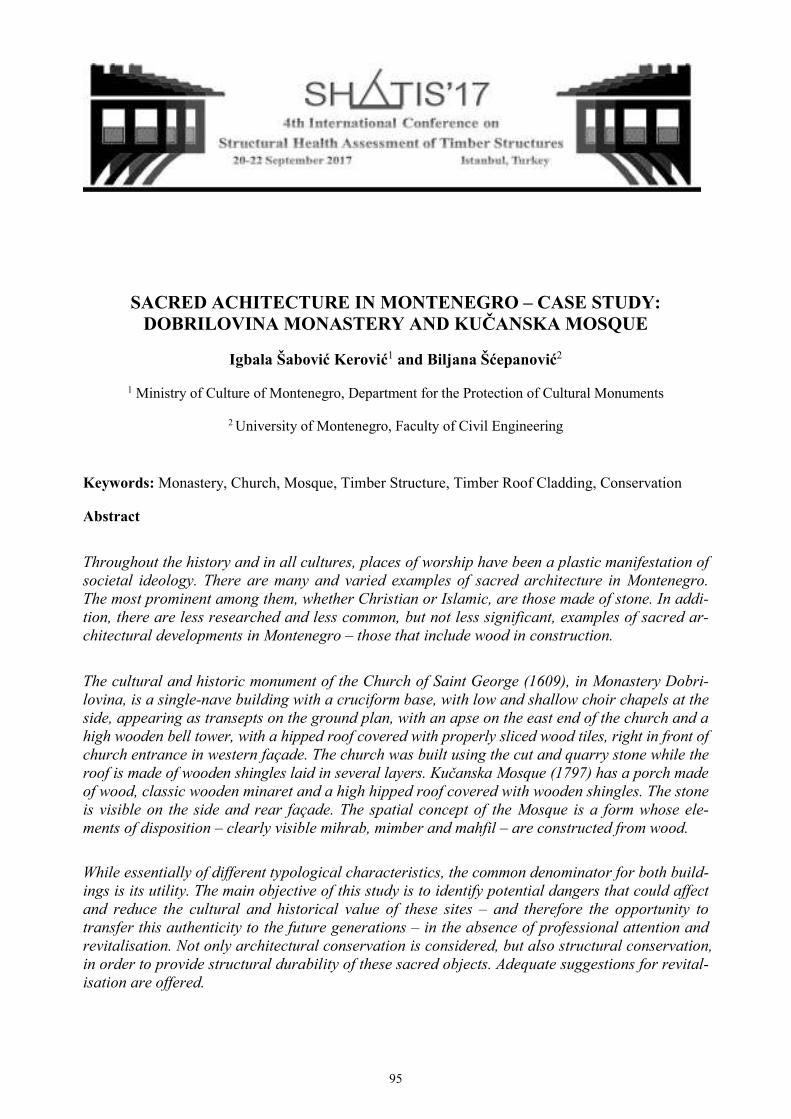
SACRED ACHITECTURE IN MONTENEGRO – CASE STUDY: DOBRILOVINA MONASTERY AND KUČANSKA MOSQUE
Igbala Šabović Kerović1 and Biljana Šćepanović2
1 Ministry of Culture of Montenegro, Department for the Protection of Cultural Monuments
2 University of Montenegro, Faculty of Civil Engineering
Keywords: Monastery, Church, Mosque, Timber Structure, Timber Roof Cladding, Conservation
Abstract
Throughout the history and in all cultures, places of worship have been a plastic manifestation of
societal ideology. There are many and varied examples of sacred architecture in Montenegro.
The most prominent among them, whether Christian or Islamic, are those made of stone. In addi-
tion, there are less researched and less common, but not less significant, examples of sacred ar-
chitectural developments in Montenegro – those that include wood in construction.
The cultural and historic monument of the Church of Saint George (1609), in Monastery Dobri-
lovina, is a single-nave building with a cruciform base, with low and shallow choir chapels at the
side, appearing as transepts on the ground plan, with an apse on the east end of the church and a
high wooden bell tower, with a hipped roof covered with properly sliced wood tiles, right in front of
church entrance in western façade. The church was built using the cut and quarry stone while the
roof is made of wooden shingles laid in several layers. Kučanska Mosque (1797) has a porch made
of wood, classic wooden minaret and a high hipped roof covered with wooden shingles. The stone
is visible on the side and rear façade. The spatial concept of the Mosque is a form whose ele-
ments of disposition – clearly visible mihrab, mimber and mahfil – are constructed from wood.
While essentially of different typological characteristics, the common denominator for both build-
ings is its utility. The main objective of this study is to identify potential dangers that could affect
and reduce the cultural and historical value of these sites – and therefore the opportunity to
transfer this authenticity to the future generations – in the absence of professional attention and
revitalisation. Not only architectural conservation is considered, but also structural conservation,
in order to provide structural durability of these sacred objects. Adequate suggestions for revital-
isation are offered.
95
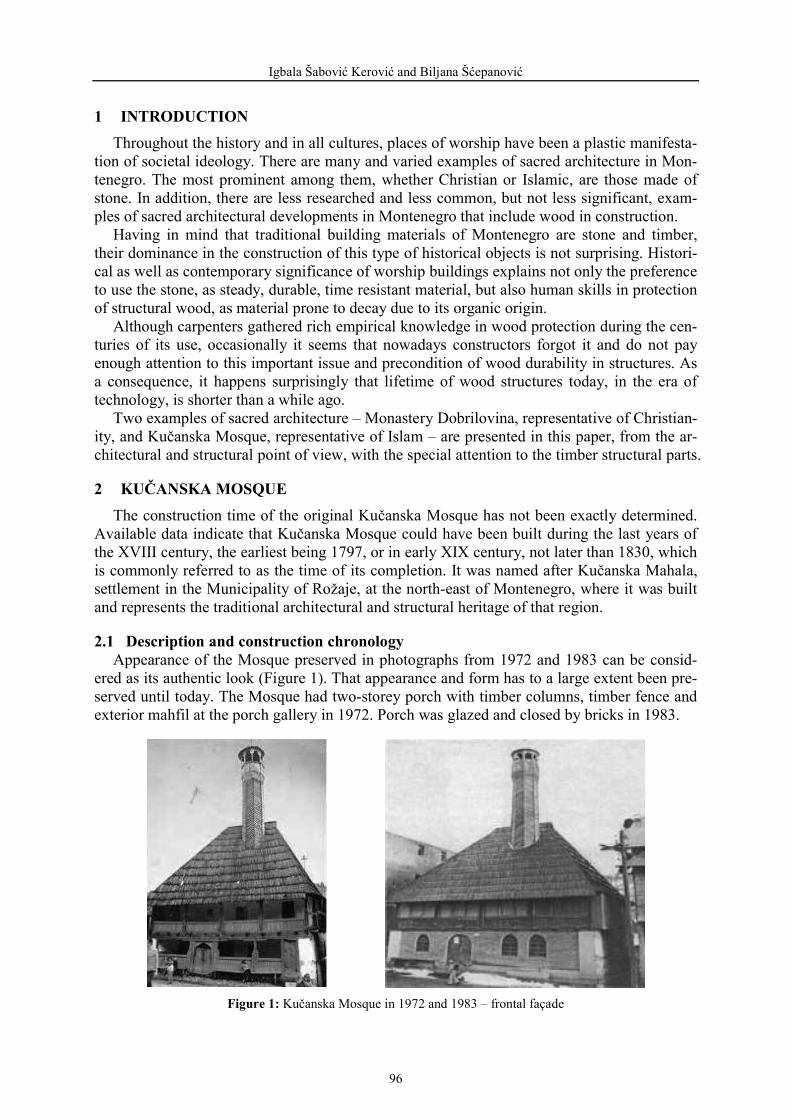
Igbala Šabović Kerović and Biljana Šćepanović
1 INTRODUCTION Throughout the history and in all cultures, places of worship have been a plastic manifesta-
tion of societal ideology. There are many and varied examples of sacred architecture in Mon-tenegro. The most prominent among them, whether Christian or Islamic, are those made of stone. In addition, there are less researched and less common, but not less significant, exam-ples of sacred architectural developments in Montenegro that include wood in construction.
Having in mind that traditional building materials of Montenegro are stone and timber, their dominance in the construction of this type of historical objects is not surprising. Histori-cal as well as contemporary significance of worship buildings explains not only the preference to use the stone, as steady, durable, time resistant material, but also human skills in protection of structural wood, as material prone to decay due to its organic origin.
Although carpenters gathered rich empirical knowledge in wood protection during the cen-turies of its use, occasionally it seems that nowadays constructors forgot it and do not pay enough attention to this important issue and precondition of wood durability in structures. As a consequence, it happens surprisingly that lifetime of wood structures today, in the era of technology, is shorter than a while ago.
Two examples of sacred architecture – Monastery Dobrilovina, representative of Christian-ity, and Kučanska Mosque, representative of Islam – are presented in this paper, from the ar-chitectural and structural point of view, with the special attention to the timber structural parts.
2 KUČANSKA MOSQUE The construction time of the original Kučanska Mosque has not been exactly determined.
Available data indicate that Kučanska Mosque could have been built during the last years of the XVIII century, the earliest being 1797, or in early XIX century, not later than 1830, which is commonly referred to as the time of its completion. It was named after Kučanska Mahala, settlement in the Municipality of Rožaje, at the north-east of Montenegro, where it was built and represents the traditional architectural and structural heritage of that region.
2.1 Description and construction chronology Appearance of the Mosque preserved in photographs from 1972 and 1983 can be consid-
ered as its authentic look (Figure 1). That appearance and form has to a large extent been pre-served until today. The Mosque had two-storey porch with timber columns, timber fence and exterior mahfil at the porch gallery in 1972. Porch was glazed and closed by bricks in 1983.
Figure 1: Kučanska Mosque in 1972 and 1983 – frontal façade
96
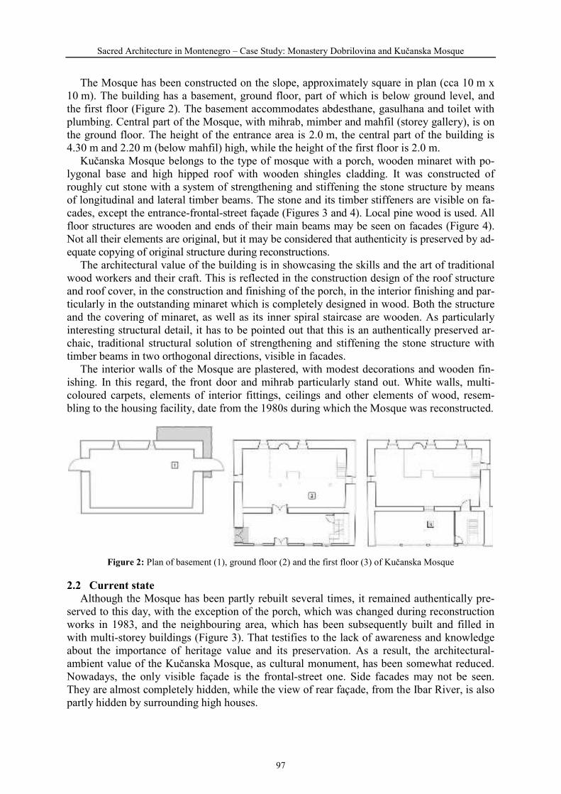
Sacred Architecture in Montenegro – Case Study: Monastery Dobrilovina and Kučanska Mosque
The Mosque has been constructed on the slope, approximately square in plan (cca 10 m x 10 m). The building has a basement, ground floor, part of which is below ground level, and the first floor (Figure 2). The basement accommodates abdesthane, gasulhana and toilet with plumbing. Central part of the Mosque, with mihrab, mimber and mahfil (storey gallery), is on the ground floor. The height of the entrance area is 2.0 m, the central part of the building is 4.30 m and 2.20 m (below mahfil) high, while the height of the first floor is 2.0 m.
Kučanska Mosque belongs to the type of mosque with a porch, wooden minaret with po-lygonal base and high hipped roof with wooden shingles cladding. It was constructed of roughly cut stone with a system of strengthening and stiffening the stone structure by means of longitudinal and lateral timber beams. The stone and its timber stiffeners are visible on fa-cades, except the entrance-frontal-street façade (Figures 3 and 4). Local pine wood is used. All floor structures are wooden and ends of their main beams may be seen on facades (Figure 4). Not all their elements are original, but it may be considered that authenticity is preserved by ad-equate copying of original structure during reconstructions.
The architectural value of the building is in showcasing the skills and the art of traditional wood workers and their craft. This is reflected in the construction design of the roof structure and roof cover, in the construction and finishing of the porch, in the interior finishing and par-ticularly in the outstanding minaret which is completely designed in wood. Both the structure and the covering of minaret, as well as its inner spiral staircase are wooden. As particularly interesting structural detail, it has to be pointed out that this is an authentically preserved ar-chaic, traditional structural solution of strengthening and stiffening the stone structure with timber beams in two orthogonal directions, visible in facades.
The interior walls of the Mosque are plastered, with modest decorations and wooden fin-ishing. In this regard, the front door and mihrab particularly stand out. White walls, multi-coloured carpets, elements of interior fittings, ceilings and other elements of wood, resem-bling to the housing facility, date from the 1980s during which the Mosque was reconstructed.
Figure 2: Plan of basement (1), ground floor (2) and the first floor (3) of Kučanska Mosque
2.2 Current state Although the Mosque has been partly rebuilt several times, it remained authentically pre-
served to this day, with the exception of the porch, which was changed during reconstruction works in 1983, and the neighbouring area, which has been subsequently built and filled in with multi-storey buildings (Figure 3). That testifies to the lack of awareness and knowledge about the importance of heritage value and its preservation. As a result, the architectural-ambient value of the Kučanska Mosque, as cultural monument, has been somewhat reduced. Nowadays, the only visible façade is the frontal-street one. Side facades may not be seen. They are almost completely hidden, while the view of rear façade, from the Ibar River, is also partly hidden by surrounding high houses.
97

Igbala Šabović Kerović and Biljana Šćepanović
Figure 3: Frontal (street) and rear (courtyard) façade of Kučanska Mosque in 2017
Figure 4: Details of frontal and rear façade of Kučanska Mosque – current state
98

Sacred Architecture in Montenegro – Case Study: Monastery Dobrilovina and Kučanska Mosque
The north-eastern part of the harem (adjacent to the building) is closed, with metal struc-ture and glass (visible on the left side of frontal façade and on the right side of rear façade, Figure 3), thereby forming a new pre-space i.e. the side entrance to the Mosque (yellow shad-ed in Figure 2), and putting out of function the original front entrance. As a result, side pas-sage to the remaining part of the Mosque courtyard covering an area close to the shore of the river Ibar is closed, while the visual aspect of the street façade has been disturbed (Figure 3).
The original semi-open entrance porch was rebuilt with bricks, while the storey gallery of porch with timber columns and wooden fence has been glazed in 1983 (Figures 1 and 4).
For the purpose of structural stabilisation, stone structure was strengthened at the south-western corner of the building by concrete retaining wall (25 years ago, according to the offi-cials of the Islamic Community of Rožaje), in the basement area (yellow shaded in Figure 2; visible on the left side of rear façade in Figures 3 and 4). From the structural point of view, the goal was accomplished and no need to question the structural quality of this solution even today. However, from the architectural aspect, this is significant devastation of the Mosque value.
Inadequate choice of modern lighting (chandeliers, ceiling fixtures, wall lamps etc.), as well as heating radiators and other visible installations reduce the value of the Mosque interior.
Timber structural elements and timber cladding are assessed by visual screening as of good quality, well protected and maintained.
2.3 Conservation The elaboration of adequate restoration and conservation project should consider: interior (from aesthetic, artistic, historical and cultural point of view) – using adequate solutions for installations, the appropriate choice for furniture and individual exhibits which are not sufficiently original;
exterior (from the architectural aspect) – removing and/or hiding contemporary installa-tions, AC units etc. that violate original appearance of the Mosque; removing the flanked extension along the north-eastern façade; re-establishing the authentic appearance, mate-rialisation and organisation, as well as original function of the entrance porch, with the front entrance; analysing possibility of replacement of massive concrete retaining wall on side-rear-façade corner with less visible and lighter structural retrofitting solution;
structure – thorough inspection of complete structure, both stone and timber parts; inter-vention in case of cracks, dampness or any other deterioration, particularly caring of mortar in stone walls; intervention in case of cracking, splitting or decay of timber; ade-quate protection and further maintenance of well-preserved or new elements of timber structure and/or cladding, so to provide durability and prolong their lifetime.
3 MONASTERY DOBRILOVINA Little is known about the founding of the Monastery of St George in Dobrilovina. It cer-
tainly existed before 1592 when the Turkish government issued permission for the repair of the ruined church in Dobrilovina. Among the locals it is also known as Mala Morača (Little Morača), because its appearance resembles Morača Monastery, and it is thought to be a lega-cy of the Nemanjić Dynasty, just like Morača Monastery. The church that may be seen today was built in 1609, as evidenced by the inscription above the naos door. There had been also an older church in this location. During the tumultuous history, from 1609 until the beginning of the XX century, the Monastery suffered several changes. Situated in the picturesque area of the Tara Canyon, among the rocky cliffs, on the gentle plateau of the village Gornja Dobri-lovina, the Municipality of Mojkovac, at the north of Montenegro, it is one of the most signif-icant cultural and historic monuments of this region.
99

Igbala Šabović Kerović and Biljana Šćepanović
3.1 Description and construction chronology In the middle of the XVIII century the Monastery was reconstructed and the church was re-
covered with wooden shingles. During the XIX century the Monastery was attacked, ruined and repaired several times. Reconstruction from the 1880 is clearly observed on the frontal (western) façade of the narthex. During these works, fresco-painting on the exterior side of frontal façade wall was ruined and wooden porch that had been in front of the church, having role of fresco-painting protection, was replaced by wooden bell tower. Nowadays the Monastery is recognisable by its prominent wooden bell tower in front of the entrance-western façade of the church. The church was reconstructed last time in 1990 when new monastery lodgings were built as well (Fig-ure 5). The ruins of the old lodgings are in the immediate vicinity of the Monastery courtyard.
The church was fresco-painted at the beginning of XVII century. Due to the frequent de-structions, frescoes have been only partially preserved, and plaster ornaments of vine leaves and rosettes, made in a very shallow relief, can also be seen.
Figure 5: The church of St George and new lodgings (1990) in Monastery Dobrilovina, 2017
Figure 6: Monastery Dobrilovina – church plan and longitudinal section
The Church of St George is a single-nave building with a cruciform base, formed by main nave with the lateral transept ended in rectangular, shallow and low choir chapels at the sides. Semi-circular apse is on the east and narthex on the west end of the main church nave. Circular dome is above the crossing of main nave and lateral transept (Figure 6). The Monastery church was built of cut and quarry stone, settled in rather regular horizontal rows, with lime mortar.
Main nave has gabled roof, choir chapels are with pent roof, while the roof of dome and apse is in cone shape. Complete roof structure is made of wood, above stone structure. Roof cladding is made of wooden shingles laid in several layers, over the timber roof structure.
A high wooden bell tower has a hipped roof covered with properly sliced wooden shingles. The lower part of the bell tower is built in the form of an open portico (Figure 7).
100

Sacred Architecture in Montenegro – Case Study: Monastery Dobrilovina and Kučanska Mosque
Figure 7: Wooden bell tower of Monastery Dobrilovina
101
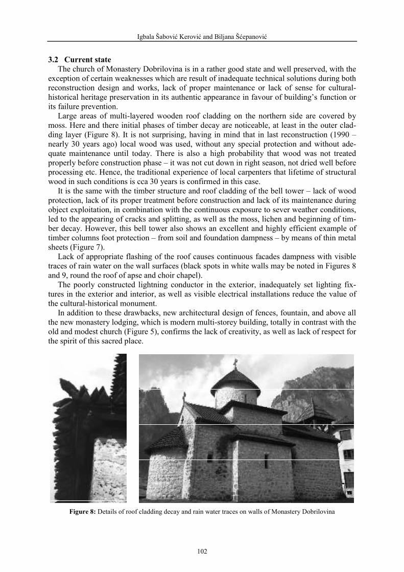
Igbala Šabović Kerović and Biljana Šćepanović
3.2 Current state The church of Monastery Dobrilovina is in a rather good state and well preserved, with the
exception of certain weaknesses which are result of inadequate technical solutions during both reconstruction design and works, lack of proper maintenance or lack of sense for cultural-historical heritage preservation in its authentic appearance in favour of building’s function or its failure prevention.
Large areas of multi-layered wooden roof cladding on the northern side are covered by moss. Here and there initial phases of timber decay are noticeable, at least in the outer clad-ding layer (Figure 8). It is not surprising, having in mind that in last reconstruction (1990 – nearly 30 years ago) local wood was used, without any special protection and without ade-quate maintenance until today. There is also a high probability that wood was not treated properly before construction phase – it was not cut down in right season, not dried well before processing etc. Hence, the traditional experience of local carpenters that lifetime of structural wood in such conditions is cca 30 years is confirmed in this case.
It is the same with the timber structure and roof cladding of the bell tower – lack of wood protection, lack of its proper treatment before construction and lack of its maintenance during object exploitation, in combination with the continuous exposure to sever weather conditions, led to the appearing of cracks and splitting, as well as the moss, lichen and beginning of tim-ber decay. However, this bell tower also shows an excellent and highly efficient example of timber columns foot protection – from soil and foundation dampness – by means of thin metal sheets (Figure 7).
Lack of appropriate flashing of the roof causes continuous facades dampness with visible traces of rain water on the wall surfaces (black spots in white walls may be noted in Figures 8 and 9, round the roof of apse and choir chapel).
The poorly constructed lightning conductor in the exterior, inadequately set lighting fix-tures in the exterior and interior, as well as visible electrical installations reduce the value of the cultural-historical monument.
In addition to these drawbacks, new architectural design of fences, fountain, and above all the new monastery lodging, which is modern multi-storey building, totally in contrast with the old and modest church (Figure 5), confirms the lack of creativity, as well as lack of respect for the spirit of this sacred place.
Figure 8: Details of roof cladding decay and rain water traces on walls of Monastery Dobrilovina
102

Sacred Architecture in Montenegro – Case Study: Monastery Dobrilovina and Kučanska Mosque
3.3 Conservation The following should be considered through the elaboration of adequate restoration and
conservation project: implementation of archaeological and conservation research of the Monastery courtyard, with the aim to provide conditions for adequate design approach in the organisation of the courtyard, in line with the authentic position and plan of courtyard and belonging buildings and objects;
analysis of the possibility of lodging relocation outside the Monastery courtyard, which would improve the visual amenity value of the church;
restoration and repair of the church – detailed inspection of all timber structural and clad-ding elements in church roof and bell tower, followed by necessary repair/replacement; ad-equate timber protection and further maintenance of all wooden elements; appropriate roof flashing in order to protect lower layers of timber parts and stone walls from damp-ness and rain water traces; removal of existing water traces on stone facades; removal and/or hiding of visible contemporary installations that disturb traditional church interior and exterior appearance.
4 CONCLUSIONS Certain weaknesses of both sites are result of missing professional treatment in the imple-
mentation of adequate reconstruction, through its design as well as through realisation phase, or due to the lack of buildings maintenance. Previous reconstructions and recovery works were mostly governed by need to provide function of these objects or to prevent their collapse. Earli-er lack of awareness and knowledge about the importance of heritage value and its preservation is obvious. As a result, the architectural-ambient value of the Monastery Dobrilovina (Figure 9) and the Kučanska Mosque (Figure 10), as cultural and historical monuments of great signifi-cance for their regions, has been somewhat reduced. Fortunately, they are not seriously structur-ally endangered and they are in full, active and safe use. However, it is right moment to inspect their structures thoroughly and, depending on results, to suggest and realise adequate repair works, as a part of much more comprehensive rehabilitation and conservation project that will take into consideration different aspects – cultural, historical, architectural as well as structural.
In order to protect these heritage monuments from further devastation, to improve their current state and to maintain their authentic values for future generations, the first step would be detailed and organised research on their authenticity and originality. Findings would be valid base for elaboration of high quality rehabilitation, preservation and conservation design, which need to engage in team work professionals of different profiles and specialisations: his-torians, artists, architects, structural engineers etc. Special attention should be devoted to the realisation phase, particularly regarding timber structural parts. All specificities of wood as a building material (organic, non-homogeneous, anisotropic, of grain structure etc.) should be carefully considered and respected, starting from the (well chosen) moment of wood cutting, through controlled processing of timber structural and cladding elements up to their skilful assembling in construction. Traditional techniques, crafts and building materials should be giv-en an advantage in the restoration and conservation design and realisation. Contemporary mate-rials and methods should be used only in case traditional skills and materialisation may not provide adequate results. Local materials, primarily wood, should have priority in use. Last but not least, adequate wood protection (primarily structural, but also chemical) and its mainte-nance, as well as proper maintenance of the whole structure is necessary in order to provide durability and long lifetime of objects.
103

Igbala Šabović Kerović and Biljana Šćepanović
Figure 9: Monastery Dobrilovina – the Church of St George
Figure 10: Kučanska Mosque
104

Sacred Architecture in Montenegro – Case Study: Monastery Dobrilovina and Kučanska Mosque
REFERENCES [1] Deroko, A. 1962. Monumentalna i dekorativna arhitektura u srednjovjekovnoj Srbiji. Be-ograd. [2] Main design on Monastery Dobrilovina recovery, Ministry of Culture of Montenegro, 1983. [3] Bećirbegović, M. 1999. Džamije sa drvenom munarom u Bosni i Hercegovini. Sarajevo. [4] Čilikov, A., Pejović, T. 2011. Pravoslavni manastiri u Crnoj Gori. Beograd. [5] Šabović Kerović, I. 2011. Transformation of typo-morphological features of settlements of
oriental origin in Montenegro. PhD thesis, Faculty of Architecture, University of Sarajevo. [6] Elaborate on valorisation of heritage property Kučanska Mosque, Ministry of Culture of Montenegro, Cetinje, 2016.
105

106
SURFACE COATINGS OF EXPOSED TIMBER ELEMENTS IN THE SECOND HALF OF THE NINETE ENTH CENTURY IN OTTOMAN
ISTANBUL
Damla Acar1
1 Turkish National Assembly, National Palaces Department, Istanbul, Turkey
Keywords: Nineteenth Century Istanbul, Timber Surface Coatings, Linseed Oil Paint, Animal Glue Paint
Abstract
Traditional surface coatings, which are the most fragile elements of historic timber constructions, are rarely present on-site. Most of the exposed timber surfaces are scraped or re-painted in the process of conservation. Even if the original surface coating layers are present the laboratory analyses are not precise in detecting the type or ratio of the elements that constitute the coating.
This paper traces the surface coating techniques applied on the exposed timber façades in nine- teenth century Ottoman Istanbul, through Ottoman textbooks, building cost estimates, and con- tracts preserved in different archives in Turkey. Late nineteenth century Ottoman textbooks written for the newly established Military Engineering Schools in Istanbul distinguish between two main types of timber surface coatings; Linseed oil-lead based pastes and paints and water- animal glue based pastes and paints. These textbooks give the ratio of materials such as animal glue, boiled linseed oil, turpentine oil and French lead white included in the coatings and de- scribe the application of the multi-layered finishing.
Ottoman building cost estimates and con- tracts prepared by Imperial Building Department (Ebniye-i Seniyye Anbarı) in the second half of the nineteenth century reveal the predominant usage of linseed oil based pastes and paints as surface coatings of timber façades. The characterization of nineteenth century surface coatings is of crucial importance for timber façade conservation, since the contemporary synthetic pastes and paints are usually incompatible with historic fabric or timber materials and are aging differ- ently from the traditional coatings.
107

Damla Acar
1 INTRODUCTION
Timber or half-timber buildings used to be the traditional constructions in many regions of Turkey: Western, Central and Southern Anatolia and Black Sea region. Half-timber structure constructed with adobe or brick filled timber frame (hımış) was the traditional residential con- struction method from the sixteenth to mid-nineteenth century in Ottoman Istanbul as well. These hımış constructions were gradually replaced by the timber frame buildings without any infill in the second half of the nineteenth century [1]. Load bearing system was not the only sub-system that was affected by the rationalization of construction techniques at that period; the façade finishing technique had its own evolution pattern. The slaked lime plaster or earth- en clay plasters that covered the façades of many hımış buildings in Istanbul were replaced by timber covering planks nailed to the posts and vertical braces of the timber frame. The plas- tered façades of hımış buildings co-existed with timber plank covered façades during the nine- teenth century; however plasters almost completely disappeared from the cityscape of timber neighborhoods at the beginning of the twentieth century. (Fig.1) Thus, timber framed build- ings covered with thin timber planks constitute the common image of traditional residential architecture in Istanbul today. (Fig.2)
Figure 1: Küçük Ayasofya Cami Street in 1870s (G. Berggren)
108
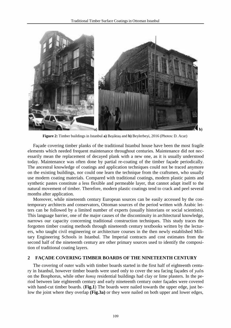
Traditional Timber Surface Coatings in Ottoman Istanbul
a) b)
Figure 2: Timber buildings in Istanbul a) Beşiktaş and b) Beylerbeyi, 2016 (Photos: D. Acar)
Façade covering timber planks of the traditional Istanbul house have been the most fragile elements which needed frequent maintenance throughout centuries. Maintenance did not nec- essarily mean the replacement of decayed plank with a new one, as it is usually understood today. Maintenance was often done by partial re-coating of the timber façade periodically. The ancestral knowledge of coatings and application techniques could not be traced anymore on the existing buildings, nor could one learn the technique from the craftsmen, who usually use modern coating materials. Compared with traditional coatings, modern plastic paints and synthetic pastes constitute a less flexible and permeable layer, that cannot adapt itself to the natural movement of timber. Therefore, modern plastic coatings tend to crack and peel several months after application.
Moreover, while nineteenth century European sources can be easily accessed by the con- temporary architects and conservators, Ottoman sources of the period written with Arabic let- ters can be followed by a limited number of experts (usually historians or social scientists). This language barrier, one of the major causes of the discontinuity in architectural knowledge, narrows our capacity concerning traditional construction techniques. This study traces the forgotten timber coating methods through nineteenth century textbooks written by the lectur- ers, who taught civil engineering or architecture courses in the then newly established Mili- tary Engineering Schools in Istanbul. The Imperial contracts and cost estimates from the second half of the nineteenth century are other primary sources used to identify the composi- tion of traditional coating layers.
2 FAÇADE COVERING TIMBER BOARDS OF THE NINETEENTH CENTURY
The covering of outer walls with timber boards started in the first half of eighteenth centu- ry in Istanbul, however timber boards were used only to cover the sea facing façades of yalıs on the Bosphorus, while other hımış residential buildings had clay or lime plasters. In the pe- riod between late eighteenth century and early nineteenth century outer façades were covered with hand-cut timber boards. (Fig.1) The boards were nailed towards the upper edge, just be- low the joint where they overlap (Fig.3a) or they were nailed on both upper and lower edges,
109

Damla Acar
which were inclined so as to prevent the water leakage into the building. (Fig.3b) The second half of the nineteenth century witnessed the emergence of timber boards with tenon-mortise or half-grooved connections. These timber boards became factory-shaped at the end of the nine- teenth century with the establishment of Ahırkapı Timber Factory in Istanbul [2]. (Fig.4)
a) b)
Figure 3. Timber façade covering boards from a) Ali Talat drawings [3] and b) Tuzcuğlu House at Beylerbeyi [4]
a) b)
Figure 4. Machine shaped boards a) drawing and b) façade of a house at Prinkipo Island, Istanbul (Drawing and Photo: D. Acar)
Either hand-cut or factory-shaped, façade covering boards were cut from pine trees grown in Western Anatolia (near Izmir) or Western Black Sea region (near Bartın). The origin of the
110
Traditional Timber Surface Coatings in Ottoman Istanbul
timber could be easily traced through the imperial contracts or accounts from the second half of the nineteenth century [5]. The thickness of timber boards varied between 1,5 cm and 3 cm. The boards were nailed to the vertical timber braces and posts with thin wrought iron nails or factory produced wire nails. (Fig.4b) Without any protective coating, the humid marine cli- mate of Istanbul would cause fast deterioration of exposed timber planks. The following sec- tion focuses on application of protective façade coatings in the second half of the nineteenth century in Istanbul.
3 TRADITIONAL COATINGS OF EXP OSED TIMBER FAÇADES
3.1 Linseed oil based pastes and paints Linseed oil based pastes used in the second half of the nineteenth century in Istanbul were
basically prepared with finely grounded lead mineral (kaba üstübeç) in a boiled linseed oil medium. A textbook on “Architecture and Construction Technology” by Ömer Şevki (1894) points out that the lead mineral is quarried from Istinye (in the vicinity of Istanbul) and is finely grounded before mixed with boiled linseed oil [6]. The chemical composition of lead mineral extracted from Istiniye quarry is unknown today. Two to three kilograms of finely crushed lead mineral were mixed with one kilogram of boiled linseed oil to make a paste [6, 7]. This paste was applied on joints of timber boards, nailheads, knots and cracks before the priming paint layer [6]. (Table 1) Some sources state that the knots on the timber boards should be burned with nitric acid (kezzap) before painting [8].
The first coating layer applied on the exposed timber surface is the priming paint layer prepared with two kilograms of “Spanish lead white” (İspanyol üstübeci), one kilogram of boiled linseed oil and one kilogram of boiled turpentine oil (neft) as thinner [6]. Good quality turpentine oil is described in nineteenth century textbooks as clear liquid oil which smells like pinewood, whereas bad quality turpentine oil is described as black-yellowish liquid, smelling like gas oil [9]. Thus, it is understood that good turpentine oil was produced mainly from co- nifers’ resin. The best quality turpentine oil used in nineteenth century Istanbul was imported from America and Marseilles, however “Moscow turpentine” and “Euboea (Eğriboz) turpen- tine” were also recorded in the imperial Ottoman contracts [10].
“Spanish lead white” used in the priming paint layer was either a lead white pigment im- ported from Spain or it was a generic name used to identify the composition of the pigment. “Spanish white” is described in the early nineteenth century sources as “finely prepared chalk” [11] or “pure clay possessing little or no coloring quality” [12]. However, “Spanish white” could be mixed with lead oxide (PbO - ceruse) in different proportions and used as white pigment as well [13]. Although the chemical composition of the pigment named “Span- ish lead white” (İspanyol üstübeci) is unknown, it is emphasized in the Ottoman textbooks that the pigment should be used only in the priming paint layer, which suggests that it is not the best quality lead white pigment [6]. (Table 1)
After drying of the priming paint layer, linseed oil paste was applied as a second coating layer on all exposed timber surfaces. The paste is applied as a very thin coat. The textbooks warn about the application of thick linseed oil putty coat, which easily cracks in the process of drying and damages the upper paint layers [6]. (Table 1) The priming paint prepared with “Spanish lead white” in a boiled linseed oil medium, thinned with turpentine was applied again on the putty layer. Putty and priming paint coats were left to dry for 15 days before the application of the upper paint layers [8]. (Table 1)
The last coats to be applied on the timber façade were two paint layers prepared by mix- ing three kilograms of “French lead white” (Fransız üstübeci), one kilogram of boiled linseed oil and one kilogram of boiled turpentine oil as thinner [6, 9]. (Table 1) The addition of any
111
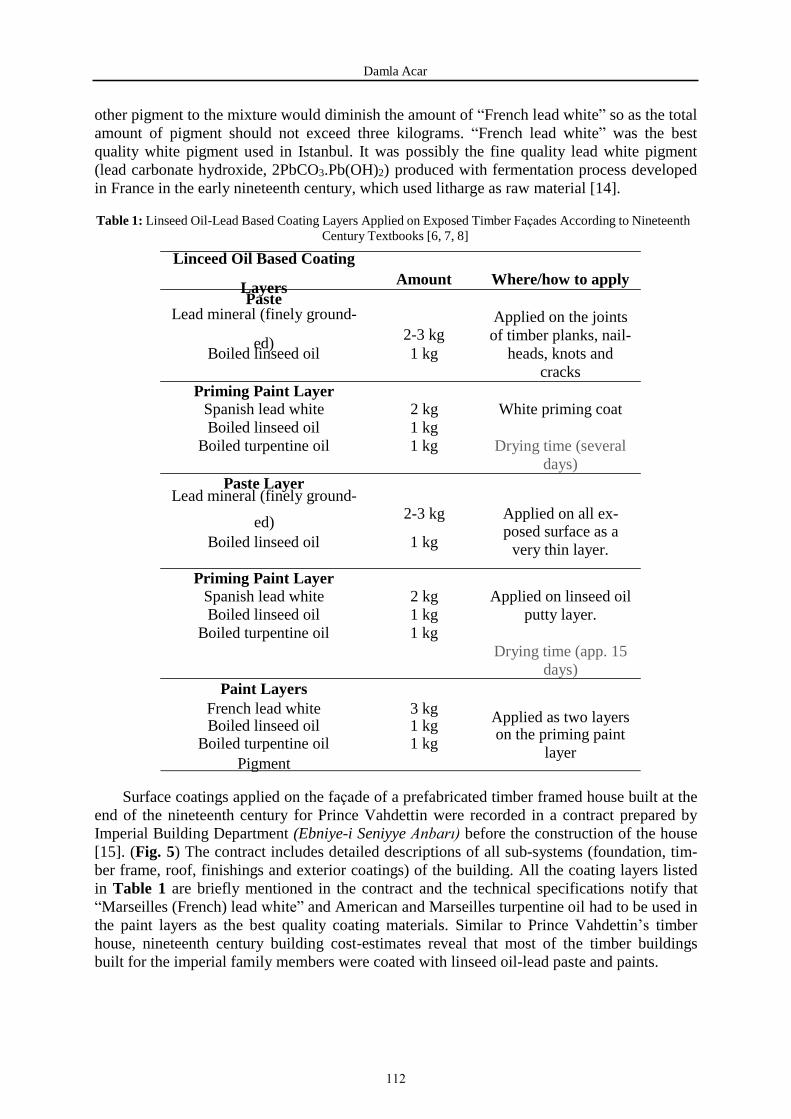
Damla Acar
other pigment to the mixture would diminish the amount of “French lead white” so as the total amount of pigment should not exceed three kilograms. “French lead white” was the best quality white pigment used in Istanbul. It was possibly the fine quality lead white pigment (lead carbonate hydroxide, 2PbCO3.Pb(OH)2) produced with fermentation process developed in France in the early nineteenth century, which used litharge as raw material [14].
Table 1: Linseed Oil-Lead Based Coating Layers Applied on Exposed Timber Façades According to Nineteenth Century Textbooks [6, 7, 8]
Linceed Oil Based Coating
Layers Amount Where/how to apply Paste
Lead mineral (finely ground-
ed) 2-3 kg Boiled linseed oil 1 kg
Priming Paint Layer
Applied on the joints of timber planks, nail-
heads, knots and cracks
Spanish lead white 2 kg White priming coat Boiled linseed oil 1 kg
Boiled turpentine oil 1 kg
Paste Layer Lead mineral (finely ground-
Drying time (several days)
ed) 2-3 kg Applied on all ex- posed surface as a
Boiled linseed oil 1 kg
Priming Paint Layer
very thin layer.
Spanish lead white 2 kg Applied on linseed oil Boiled linseed oil 1 kg
Boiled turpentine oil 1 kg
Paint Layers
putty layer.
Drying time (app. 15 days)
French lead white 3 kg Applied as two layers Boiled linseed oil 1 kg Boiled turpentine oil 1 kg
on the priming paint layer
Pigment
Surface coatings applied on the façade of a prefabricated timber framed house built at the end of the nineteenth century for Prince Vahdettin were recorded in a contract prepared by Imperial Building Department (Ebniye-i Seniyye Anbarı) before the construction of the house [15]. (Fig. 5) The contract includes detailed descriptions of all sub-systems (foundation, tim- ber frame, roof, finishings and exterior coatings) of the building. All the coating layers listed in Table 1 are briefly mentioned in the contract and the technical specifications notify that “Marseilles (French) lead white” and American and Marseilles turpentine oil had to be used in the paint layers as the best quality coating materials. Similar to Prince Vahdettin’s timber house, nineteenth century building cost-estimates reveal that most of the timber buildings built for the imperial family members were coated with linseed oil-lead paste and paints.
112
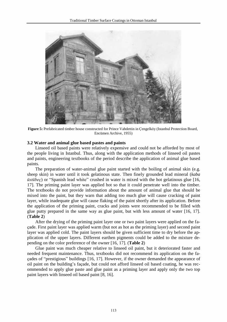
Traditional Timber Surface Coatings in Ottoman Istanbul
Figure 5: Prefabricated timber house constructed for Prince Vahdettin in Çengelköy (Istanbul Protection Board, Encümen Archive, 1955)
3.2 Water and animal glue based pastes and paints Linseed oil based paints were relatively expensive and could not be afforded by most of
the people living in Istanbul. Thus, along with the application methods of linseed oil pastes and paints, engineering textbooks of the period describe the application of animal glue based paints.
The preparation of water-animal glue paint started with the boiling of animal skin (e.g. sheep skin) in water until it took gelatinous state. Then finely grounded lead mineral (kaba üstübeç) or “Spanish lead white” crushed in water is mixed with the hot gelatinous glue [16, 17]. The priming paint layer was applied hot so that it could penetrate well into the timber. The textbooks do not provide information about the amount of animal glue that should be mixed into the paint, but they warn that adding too much glue will cause cracking of paint layer, while inadequate glue will cause flaking of the paint shortly after its application. Before the application of the priming paint, cracks and joints were recommended to be filled with glue putty prepared in the same way as glue paint, but with less amount of water [16, 17]. (Table 2)
After the drying of the priming paint layer one or two paint layers were applied on the fa- çade. First paint layer was applied warm (but not as hot as the priming layer) and second paint layer was applied cold. The paint layers should be given sufficient time to dry before the ap- plication of the upper layers. Different earthen pigments could be added to the mixture de- pending on the color preference of the owner [16, 17]. (Table 2)
Glue paint was much cheaper relative to linseed oil paint, but it deteriorated faster and needed frequent maintenance. Thus, textbooks did not recommend its application on the fa- çades of “prestigious” buildings [16, 17]. However, if the owner demanded the appearance of oil paint on the building’s façade, but could not afford linseed oil based coating, he was rec- ommended to apply glue paste and glue paint as a priming layer and apply only the two top paint layers with linseed oil based paint [8, 16].
113

Damla Acar
Table 2: Water-Animal Glue Based Coating Layers Applied on Exposed Timber Façades According to Nine- teenth Century Textbooks [16, 17]
Water-Glue based coating
layers Amount Where/How to apply Glue Paste
Lead mineral (finely ground-
ed) Applied on the joints of
Water Animal glue (gelatinous state)
Priming paint layer Lead mineral (finely ground-
timber planks, knots and cracks.
Applied hot.
ed) or Spanish lead white 1 kg
Applied hot. Water 0,56 kg
Animal glue (gelatinous state)
Paint Layers Lead mineral (finely ground-
ed) or Spanish lead white 1 kg
Water 0,56 kg
Animal glue (gelatinous state) Pigment (earthen)
Drying time
First layer applied warm. Second layer applied
cold.
Drying time for each lay- er
4 DISCUSSION AND CONCLUSION
Timber covered buildings were decorated with either linseed oil-lead based coatings or water-glue based paints in the nineteenth century. While linseed oil paints were used predom- inantly on the façades of ‘prestigious’ buildings in prosperous neighborhoods, water-animal glue based paints were the common practice in the poor neighborhoods. Linseed oil-lead based paints cycles of external re-decoration varied between 5 to 10 years [18], while glue based paints needed more frequent maintenance. Ottoman sources reveal that, traditional tim- ber coatings were prepared using local materials like lead mineral quarried from Istiniye, boiled linseed oil and animal skin glue together with imported materials like “Spanish lead white”, “French lead white” and turpentine oil. Since the ratio and the type of materials in- cluded in each coating layer are clearly described in the nineteenth century Ottoman textbooks, the traditional linseed oil-lead coatings or water-animal glue coatings can be easily repro- duced and used. However the usage of lead based paints is strictly regulated in many coun- tries due to their toxicity. To avoid the harmful effect of lead white, zinc oxide have been used as white pigment since mid-nineteenth century in Europe, but the paint layer of zinc white and linseed oil have not been as flexible as the layer composed of lead white and linseed oil. In order to retain certain flexibility of the paint layer lead/zinc blend have been also used as white pigment in linseed oil medium [19]. Lead-free linseed oil paints are used mainly in Scandinavian countries, but there is not enough evidence about how they age in humid marine climate.
Nowadays architects and restorers generally apply modern paints with plastic binders on exposed timber surfaces in the restoration works. However, these external wall coatings used for finishing the exposed timber walls are incompatible with historic fabric or materials and are aging differently from the traditional finishes. Traditional linseed oil-lead based paint
114

Traditional Timber Surface Coatings in Ottoman Istanbul
weather in a characteristic way, rather than become brittle and cracking, the paint gradually ‘chalk’ away to a matt surface. (Fig. 6) Weathered surface could be easily recoated after a few years without removing any rest paint from the surface. The texture and surface of weathered historic buildings significantly influence the public attitude towards timber heritage.
a)
b)
Figure 6: Roof forefront of Prince Kemaleddin’s house in Dolmabahçe Palace showing the aging of a) linseed oil paint (1966 – Turkish National Palaces Archive) and b) modern plastic paint (2008 – D.Acar)
Apart from the damages to texture, the brittle and unflexible film layer formed by modern plastic paints tends to crack and enclose the rainwater under the detached paint layers. The rainwater that cannot evaporate from the surface triggers the activity of wood decaying fungi, which leads to fast deterioration of authentic timber covering planks and the structural timber elements. Moreover, one has to remove all the plastic paint from the surface of the timber be- fore recoating, which is time consuming and threatens the integrity and texture of the surface.
The identification of the original composition, authentic application methods and ageing pattern of the traditional timber coatings, could be a starting point for building chemicals in- dustry on the way to develop non-toxic pigment which has the chemical properties of lead- white pigment.
115

Damla Acar
5 REFERENCES
[1] Acar, D. 2017. “Evolution and Rationalization of Timber Frame Design in Istanbul in the Second Half of the Nineteenth Century”. Journal of Architectural Conserva- tion, DOI:10.1080/13556207.2017.1330384, Pp:1-21.
[2] Acar, D. and Mazlum D. 2016. “Timber-Framed Houses Built for the Court Members Af- ter the 1894 Earthquake in Istanbul: Rationalization of Construction Techniques”. Interna- tional Journal of Architectural Heritage, vol.10, no:5, Pp:604-619.
[3] Ali Talat. 1911. Mühendis Mektebinde Tedris Olunan Ahşap İnşaat Eşgali (Timber Con- structions Textbook to be Taught in Engineering School – Drawings). Istanbul Technical University Library, Rare Books Archive. Figure 203.
[4] Orbay, A. 2013. “The Tuzcuoğlu House at Beylerbeyi and Restoration as an Opportunity to Re-Interpret a Building”. In Symposium on Restoration and Conservation of Timber Struc- tures 2 Proceedings, Istanbul Metropolitan Municipality, Pp. 45-51.
[5] Turkish Prime Ministry Ottoman Archives (BOA), HH.EBA. 23/50 and 23/52, Accounts of building materials, date: 1874; BOA, HH.d.28738, p.73-75, 181-183, 243-247, Imperial contracts listing the timber types bought between 1893 and 1895.
[6] Ömer Şevki. 1894. Fenn-i İnşaat ve Mimari (Architecture and Construction Technologies). Istanbul Municipality Atatürk Library, Rare Books Archive, p.133.
[7] Hasan Tevfik. 1887. Usul-i Keşf-i İnşaat (Construction Cost Estimation). Erzurum Ata- türk University Library, Rare Books Archive, p.54.
[8] Ahmed Şükrü. 1884. Fenn-i Mimari (Architecture Technologies). Erzurum Atatürk Uni- versity Library, Rare Books Archive. p.92.
[9] Celal Esad (Arseven). 1908. Yapı Malzemesi (Construction Materials). Erzurum Atatürk University Library, Rare Books Archive. p.138.
[10] BOA, HH.d. 28738, date: 1893-1896, Imperial Contracts’ Register, Pp. 18-19, 79-80, 162-163.
[11] Macfarquhar, C. and Gleig, G.(ed.). 1834. Ensyclopedia Britannica. Vol.5, Part 1, p.157.
[12] Campbell, O. 1841. Treatise on Carriage, Sign and Ornamental Painting. Published by Russel R.Lewis, N.Y., p.3.
[13] Eastaugh, E., Walsh, V., Chapin, T., and Siddall, R. 2008. Pigment Compedium- A Dic- tionary and Optical Microscopy of Historic Pigments. Elsevier , p.97.
[14] Ibid. ,Pp. 239-240.
[15] BOA, Y.PRK.HH. 28/26, date:1894, Construction Contract signed by Serge Tscherba- koff for the construction of timber house for Prince Vahdettin.
[16] Ömer Şevki. 1894. Fenn-i İnşaat ve Mimari (Architecture and Construction Technolo- gies). Istanbul Municipality Atatürk Library, Rare Books Archive, p.134-135.
[17] Celal Esad (Arseven). 1908. Yapı Malzemesi (Construction Materials). Erzurum Atatürk University Library, Rare Books Archive. p.140-141.
[18] Mccaig, I. and Ridout, B. (ed.). 2012. Timber, English Heritage Practical Building Con- servation, English Heritage, p.401.
116

Traditional Timber Surface Coatings in Ottoman Istanbul
[19] Mitchell-Rose, C. “Paint, Wood and Weather”, article reproduced from The Building Conservation Directory (2007) http://www.buildingconservation.com/articles/paintwoodweather/paintwoodweather.htm, ac- cess date: 27.03.2017.
117

118

RAPID IN-SITE SURVEY AND ASSESSMENT METHOD FORSTRUCTURAL MEMBERS IN TRADITI ONAL CHINESE TRADITIONAL
TIMBER STRUCTURE
G. Chao, W. Juan and Y. Qing Shan
Beijing’s Key Laboratory of Structural Wind Engineering and Urban Wind Environment, School of Civil Engineering, Beijing Jiaotong University, Beijing 100044, China.
Keywords: Traditional Chinese traditional timber structure, Structural members, Rapid, In-site survey, Assessment method, Visual grading
Abstract
The proper timber structure assessment is of great importance to assure safe service of buildings as well as to preserve cultural heritage objects for future generations. In order to quickly andaccurately assess the conditions of load-bearing structural members in traditional Chinese tradi-tional timber structure, a rapid in-site survey and assessment method has been proposed.
General surveys based on visual observation and simple measurements are conducted on thestructural components including column, beam and Dou-gong(bracket sets) from the following five aspects which are condition of material, condition of structural member, condition of joint,deformation of structural member and condition of reinforcement. Definitions of damage point for different structural members are defined. Grading of structural members is determined ac-cording to the number of damaged points.
Non-destructive Testing methods are carried out for the severely damaged members as well as the randomly selected members to validate the results of general survey. The method has been applied on a traditional multilayer timber building called Feiyun Pavilion in Shanxi Province, China. Results show that the conditions of structural components can be evaluated quickly and accurately and the proposed method provides basis for the daily inspection, maintenance and re-inforcement of wooden structures of heritage buildings.
119

G.Chao Gao, W. Juan Wang, Y. Qingshan
1 INTRODUCTION
As cultural heritage, ancient building has drawn more and more people's attention. As an independent system in the world architecture system, traditional Chinese traditional timber structure building as shown in Figure 1 is generally composed of three parts: platform, timber structural frame, and roof, regardless of size and grade. Among them, the timber skeleton in-cluding column, girder, purlin, bracket sets and other structural members is the main load-bearing part of the Traditional Chinese ancient buildings. No matter what kind of architecture form or roof form it is in, column, girder and bracket sets are the most important structure members of the timber skeleton. However, due to the biology characteristics of the wood, most timber structural members have damages in different degrees after years of change [1].Damage would affect the load bearing performance of the buildings in varying degrees, espe-cially if the main load-bearing structural members have extreme damages, the overall safety of the building will be threatened. Therefore, it is very important to detect the damages of the main load-bearing structural members and take corresponding measures to ensure the safety of the Chinese traditional timber structure and to extend the precious cultural heritage of mankind. At the present stage, there are mainly two kinds of damage detection methods for Chinese traditional timber structure, one is visual inspection with simple qualitative detection, and the other is the Non-destructive Testing by equipment, which tests the physical and me-chanical properties of structural members [2]. Visual inspection method requires rich practical experiences, otherwise it would lead to some detection errors. Non-destructive Testing is not easy for the daily management of the cultural relics preservation institute because of the ex-pensive equipment, complicated operation, and cumbersome data analysis [3-5]. In summary, a rapid in-site survey and assessment method for load-bearing structural members of Chinese traditional timber structure is needed to meet the requirements of daily inspections and timely detect various damages of the structure.
Figure 1: Composition of Chinese traditional timber structure
2 CONCEPT AND FRAME OF RAPID SURVEY AND ASSESSMENT METHOD
As mentioned, load-bearing structural members in Chinese traditional timber structure in-clude load-bearing timber columns, timber girders and bracket sets as shown in Figure 2. A large number of studies have shown that the main forms of damages to the timber structure include decay, worm damage, column tilt, girder deflection, tenon pulling out from the mor-tise and so on. It should be noted that, existing reinforcement measures of the structural mem-bers may also cause damages due to improper reinforcement or loss of their original functions. The main concept and frame of the rapid survey and assessment method is shown in Figure 3,
120
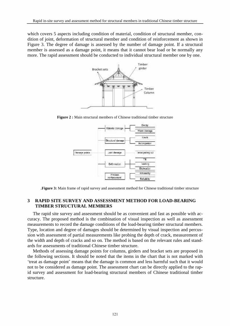
Rapid in-site survey and assessment method for structural members in traditional Chinese timber structure
which covers 5 aspects including condition of material, condition of structural member, con-dition of joint, deformation of structural member and condition of reinforcement as shown in Figure 3. The degree of damage is assessed by the number of damage point. If a structuralmember is assessed as a damage point, it means that it cannot bear load or be normally any more. The rapid assessment should be conducted to individual structural member one by one.
Figure 2 : Main structural members of Chinese traditional timber structure
.Figure 3: Main frame of rapid survey and assessment method for Chinese traditional timber structure
3 RAPID SITE SURVEY AND ASSESSMENT METHOD FOR LOAD-BEARING TIMBER STRUCTURAL MEMBERS
The rapid site survey and assessment should be as convenient and fast as possible with ac-curacy. The proposed method is the combination of visual inspection as well as assessment measurements to record the damage conditions of the load-bearing timber structural members. Type, location and degree of damages should be determined by visual inspection and percus-sion with assessment of partial measurements like probing the depth of crack, measurement of the width and depth of cracks and so on. The method is based on the relevant rules and stand-ards for assessments of traditional Chinese timber structure.
Methods of assessing damage points for columns, girders and bracket sets are proposed in the following sections. It should be noted that the items in the chart that is not marked with ‘treat as damage point’ means that the damage is common and less harmful such that it would not to be considered as damage point. The assessment chart can be directly applied to the rap-id survey and assessment for load-bearing structural members of Chinese traditional timber structure.
121
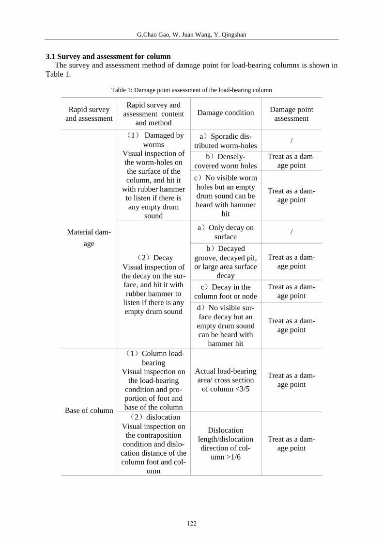
G.Chao Gao, W. Juan Wang, Y. Qingshan
3.1 Survey and assessment for column The survey and assessment method of damage point for load-bearing columns is shown in
Table 1.
Table 1: Damage point assessment of the load-bearing column
Rapid survey and assessment
Rapid survey and assessmentcontent
and methodDamage condition Damage point
assessment
Material dam-
age
1 Damaged by worms
Visual inspection of the worm-holes on the surface of the column, and hit it
with rubber hammer to listen if there is any empty drum
sound
a Sporadic dis-tributed worm-holes
/
b Densely-covered worm holes
Treat as a dam-age point
c No visible worm holes but an empty drum sound can be heard with hammer
hit
Treat as a dam-age point
2 Decay Visual inspection of the decay on the sur-face, and hit it with rubber hammer to
listen if there is any empty drum sound
a Only decay on surface
/
b Decayed groove, decayed pit, or large area surface
decay
Treat as a dam-age point
c Decay in the column foot or node
Treat as a dam-age point
d No visible sur-face decay but an empty drum sound can be heard with
hammer hit
Treat as a dam-age point
Base of column
1 Column load-bearing
Visual inspection on the load-bearing
condition and pro-portion of foot and base of the column
Actual load-bearing area/ cross section
of column <3/5
Treat as a dam-age point
2 dislocation Visual inspection on the contraposition
condition and dislo-cation distance of the column foot and col-
umn
Dislocation length/dislocation direction of col-
umn >1/6
Treat as a dam-age point
122
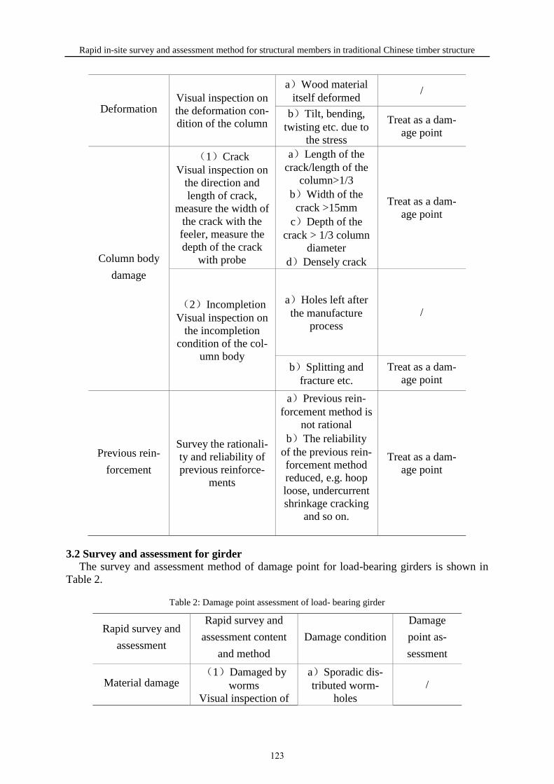
Rapid in-site survey and assessment method for structural members in traditional Chinese timber structure
Deformation Visual inspection on the deformation con-dition of the column
a Wood material itself deformed
/
b Tilt, bending, twisting etc. due to
the stress
Treat as a dam-age point
Column body
damage
1 Crack Visual inspection on
the direction and length of crack,
measure the width of the crack with the feeler, measure the depth of the crack
with probe
a Length of the crack/length of the
column>1/3 b Width of the crack >15mm
c Depth of the crack > 1/3 column
diameter d Densely crack
Treat as a dam-age point
2 Incompletion Visual inspection on
the incompletion condition of the col-
umn body
a Holes left after the manufacture
process /
b Splitting and fracture etc.
Treat as a dam-age point
Previous rein-
forcement
Survey the rationali-ty and reliability of previous reinforce-
ments
a Previous rein-forcement method is
not rational b The reliability
of the previous rein-forcement method reduced, e.g. hoop loose, undercurrent shrinkage cracking
and so on.
Treat as a dam-age point
3.2 Survey and assessment for girder The survey and assessment method of damage point for load-bearing girders is shown in
Table 2.
Table 2: Damage point assessment of load- bearing girder
Rapid survey and
assessment
Rapid survey and
assessment content
and method
Damage condition
Damage
point as-
sessment
Material damage 1 Damaged by
worms Visual inspection of
a Sporadic dis-tributed worm-
holes /
123

G.Chao Gao, W. Juan Wang, Y. Qingshan
the worm-holes on the surface of the
girder, and hit it with rubber hammer to
listen if there is any empty drum sound
b Densely-covered worm
holes
Treat as a damage point
c No visible worm holes but an empty drum sound can be heard with
hammer hit
Treat as a damage point
2 Decay Visual inspection of the decay on the sur-
face of the girder, and hit it with rubber hammer to listen if there is any empty
drum sound
a Only decay on surface
/
b Decayed groove, decayed pit, or large area surface decay
Treat as a damage point
c Decay in the end of the girder
Treat as a damage point
d No visible sur-face decay but an empty drum sound can be heard with
hammer hit
Treat as a damage point
Deformation
Visual inspection on the deformation con-dition of the girder
body
a Wood material itself deformed
/
b Tilt, distorting, bending, twisting
etc. due to the stress
Treat as a damage point
Girder damage
1 Crack Visual inspection on
the direction and length of the crack,
measure the width of the crack with the feeler, measure the depth of the crack
with probe
a Length of the crack/span >1/3 b Width of the crack >10mm
c Depth of the crack 1/3
height(width) of the girder
d Densely crack
Treat as a damage point
2 Incompletion Visual inspection on
the incompletion condition of the gird-
er body
a Holes left after the manufacture
process /
b Splitting and fracture etc.
Treat as a damage point
124

Rapid in-site survey and assessment method for structural members in traditional Chinese timber structure
Joint damage Visual inspection on the pull-out condition
of the tenon
The amount of the pull-out tenon 1/4 of the tenon
Treat as a damage point
Previous rein-
forcement
Survey the rationality and reliability of pre-vious reinforcement
method
a Previous rein-forcement method
is not rational b The reliability
of the previous reinforcement
method reduced , e.g. hoop under-current shrinkage cracking and so
on.
Treat as a damage point
3.3 Survey and assessment for bracket set The survey and assessment method of damage point for bracket sets is shown in Table 3.
Table 3: Damage point assessment of bracket sets
Rapid survey and
assessment
Rapid survey and
assessment content
and method
Damage condition
Damage
point as-
sessment
Material damage
1 Damaged by worms
Visual inspection oF the worm-holes on the surface of the bracket set
a Sporadic distribut-ed worm-holes
/
b Densely-covered worm holes on the
major bearing block
Treat as a damage point
2 Decay Visual inspection
on the decay of the bracket sets surface
a Whole bracket sur-face decayed b Decayed groove or decayed pit on the ma-
jor bearing block
Treat as a damage point
Dislocation Visual inspection on the dislocation condition of the
a Dislocation of the whole bracket
Treat as a damage point
bracket
b Dislocation of ma-jor bearing block
Treat as a damage point
c Dislocation of oth-er individual compo-nent excluding the
major bearing block
/
Bracket damage 1 Crack
Visual inspection on the location and
a Cracks on the ma-jor bearing block, and the cracks are wide or
Treat as a damage point
125
G.Chao Gao, W. Juan Wang, Y. Qingshan
condition of crack dense b Bracket obviously
or densely cracked
2 Incompletion Visual inspection
on the condition of the bracket incom-
pletion
a Deficiency of par-tial component
b Fracture of the bracket
Treat as a damage point
3 Pulling out tenon
Visual inspection on the connection
condition of brack-et
a Amount of vertical tenon pulling out of the major bearing
block 1/5 bracket opening
b Amount of vertical tenon pulling out of the major bearing block warp 1/5 bracket opening
Treat as a damage point
4 THE ASSESSMENT GUIDELINE OF LOAD-BEARING STRUCTURAL MEMBERS
According to the results of the rapid survey and assessment of the load-bearing structural members in Chinese traditional timber structure, damages of the structural members can be identified and classified according to the number, distribution and degree of damage points. The assessment results are classified into two levels and four grades according to Table 4. In the first level, structural members are non-hazardous including grade A and grade B while in the second level, structural members are dangerous including grade C and grade D.
Table 4: Damage grading assessment of the structure
Level Grade Risk Dealing suggestion
1 A Safe
May not take measures
B SafePartially take
measures
2 C Dangerous
Should take measures
D Dangerous Should take imme-
diate measures
The damage identification results of the load-bearing structural members can be used as reference for further inspection and the base of the whole structure system inspection. The specifications of damage grading are shown in Table 5.
126

Rapid in-site survey and assessment method for structural members in traditional Chinese timber structure
Table 5: Damage grading
Level Grade Standard Suggestion
1
A
The original damage points in the components have been properly rein-forced, and no new dam-
age points are found
Keep the original status of the structural mem-ber and pay attention to
daily inspection
B
a 1-2 damage points are newly discovered, but
they would not affect the normal use of the compo-nent and threaten the par-tial or whole safety of the
structure b) 3 or more than 3 dam-age points in same type
are newly discovered, but the damage points wont affect the normal use of
the component and threat-en the partial or whole safety of the structure c Original damage
points in the components have been properly rein-
forced, but there are indi-vidual reinforcement to be re-processed, otherwise it will affect the normal use
of the components
Necessary measures should be taken to the damage point, and fre-quent manual inspec-tion should be carried
out, development of the damage should be
monitored
2 C
a 1-2 damage points are newly discovered, and the damage points affect the normal use of the compo-
nent, even threaten the partial or whole safety of the structure, but the dan-
ger would not happen immediately
b 3 or more than 3 dam-age points in different
types are newly discov-ered, and it may affect the
partial or whole safety, but the danger may not happen immediately c Original damage
Necessary measures should be taken to the damage point, and fur-ther inspection to the component should be conducted with detec-
tion equipment
127

G.Chao Gao, W. Juan Wang, Y. Qingshan
points are not properly reinforced, and it would affect the normal use of the component, but not
affect the partial or whole safety of the structure
D
a The newly discovered damage points may affect the partial of whole safe-ty, accident may happen at any time, it should be processed immediately. b The original damage points are not properly reinforcement, and it
would affect the normal use of the partial or the whole structure. Safety accident may happen at any time, it must be pro-
cessed immediately
Measures should be taken immediately
5 PRACTICAL EXAMPLE OF THE PROPOSED METHOD
Feiyun Pavilion is located in Wan-rong County, south of Shanxi Province in China, which had originally been built during the Yuan Dynasty (1400 A.D.). But the existing Feiyun Pavilion as shown in Figure 4 was rebuilt at some point between 1506 and 1521 A.D. It was constructed with three floors, with a gable-and-hip roof and double-deck eaves on the top sto-ry. It is 23.19 meters high with a square plan. The load-bearing system of the building is the timber skeleton with structural members like column, beam and bracket sets etc., and both eastern and western sides are built with brick walls.
Figure 4: The geography location and elevation drawing of Feiyun Pavilion
Feiyun Pavilion as shown in Figure 5 has been in an overall repair during 2011-2013, no assessment have been conducted after the repair. A rapid in-site survey and assessment on the 129 columns, 204 girders and 212 bracket sets have been conducted with the proposed meth-od. Table 6 shows the numbers of the examined structural members. The tools used in the
128

Rapid in-site survey and assessment method for structural members in traditional Chinese timber structure
survey and assessment process including ruler, feeler, box ruler, plumb and so on shown in Figure 6.
Figure 5: The columns, girders of the third floor and the bracket set on the top of Feiyun Pavilion
Table 6: Numbers of the examined structural members of Feiyun Pavilion
floor number column girder bracket set
first floor 33 52 76
second floor 64 108 76
third floor 32 44 60
total amount 129 204 212
Figure 6: Straight ruler, feeler, box ruler and plumb
The rapid survey and assessment record the damage condition and previous reinforcement condition of Feiyun Pavilion. After the assessment results were sorted out, each structural members was graded with the results shown in Figure 7. Components with grades A and B can be considered in a non-hazardous state, which accounted for 87% columns, 97% girder and 100% bracket sets. The above structural members only need to be taken the necessary measures for individual damage points. Columns and girders with Grade C are in dangerous states. There are no components with Grade D.
Figure 7: The results of the grading
0%
50%
100%
150%
A B C D A B C D A B C D
First floor Second floor Third floor
Column
Girder
Bracket sets
129

G.Chao Gao, W. Juan Wang, Y. Qingshan
In order to test the reliability and effectiveness of the posed method, non-destructive test-ing methods are carried out for the severely damaged members as well as the randomly se-lected members. Testing equipment are FAKOPP stress wave measuring instrument and RESIST0GRAPH 4453-P micro-drill resistance meter, the detection objects covering a total of 30% columns and girders. Some test results are shown in the Figure 8.
Figure 8: Micro-drill resistance testing graph
Non-destructive testing result shows that 89.4% of the structural members which are iden-tified as grade C by the rapid assessment method have internal defects and 16.7% of the other structural members except grade C structural members are internally defective. It can be seen that the proposed rapid survey and assessment method is considered to be effective.
6 CONCLUSION
In this paper, a rapid survey and assessment method with grading classification for the structural members which is suitable for daily inspection for traditional Chinese timber struc-tures is presented. The number of damage points is taken as the reference to grade the damage status of the components. The rapid survey and assessment method has been carried out on columns, girders and bracket sets of Feiyun Pavilion. Damages of the structural members were detected and graded. The results show that more than 90% structural members of the examined structural members are grade A and B, in accordance with the Feiyun Pavilion sta-tus after the overall repair. Non-destructive testing methods have been carried out for the se-verely damaged members as well as the randomly selected members to validate the proposed method. Results show that they are in good agreement with the assessment results.
In summary, the proposed method can accurately evaluate the status of the structure com-ponents, providing basis for the daily inspection, maintenance and reinforcement of wooden structures of heritage buildings.
REFERENCES
[1] Calderoni, C. , Matteis, G.D., Giubileo. C. , and Mazzolani, F. M. 2010. “Experimental correlations between destructive and non-destructive tests on ancient timber elements” .J. Eng. Struct , 32 (2), Pp:442-448
[2] Niemz, P. and Mannes, D. 2012. “Non-destructive testing of wood and wood-based mate-rials”. J.CULT.HERIT, 13(3) , Pp: S26-S34.
[3] Wang, X., Ross, R. J., and Clellan, M. 2001. “ Nondestructive evaluation of standing trees with a stress wave method” .J. WOOD. FIBER. SCI, 33(4) , Pp: 522-533.
[4] Gwaze, D., Stevenson, A. 2008. “Genetic variation of wood density and its relationship with drill resistance in short leaf pine” .J. SOUTH. J . APPL. FOR, 32(3) , Pp: 130-133.
[5] Imposa, S., Mele, G., Corrao, M., Coco, G., and Battaglia, G. 2014. “Characterization of Decay in the Wooden Roof of the S. Agata Church of Ragusa Ibla (Southeastern Sicily) by Means of Sonic Tomography and Resistograph Penetration Tests” .J. INT J ARCHIT HERIT, 8(2) , Pp: 213-223.
130

THE VENETIAN FLOOR O F THE “BAILO BUILDING” IN CHALCIS, GREECE: DECIPHERING ITS LOST CONSTRUCTION DETAILS
Yorgos Kourmadas¹, Eleftheria Tsakanika², Panagiota Taxiarchi1
1 Conservation and Restoration of Historic Buildings and Sites, NTUA, Athens, Greece
2 School of Architecture, National Technical University of Athens, Athens, Greece
Keywords: Chalcis/Negroponte, Venetian gothic floor, Timber lacings/tie-beams, Timber floor restoration, Cantinelle
Abstract
The so-called “Bailo building” in Chalcis, Greece, was constructed over three periods: Its south-
ern part was built in the 14th century by the Venetian rulers of the city as a public loggia, its northern part in the late 18th century as a typical Ottoman residence, and it was finally renovated in the 19th century in the neoclassical style. Recently, the building was restored and will be used as a public cultural space.
The Venetian wing that survived as a two-storied masonry construction missing almost all of its original timber floor and roof, confronted the restoration team, of which the authors were part, with questions and dilemmas about its original form and the way it should be restored. The ex-tremely few authentic timber remains proved to be an invaluable source of information and the solution to the restoration puzzle. The main working tool was a thorough constructional analysis of the scarce timber remains, coupled with dendrochronological, historical and bibliographical research that led to the identification of the floor as a variant of the “Venetian gothic floor” type,
of which very few have survived, most notably at the Doge’s Palace in Venice.
This research procedure led firstly to a graphic reconstruction of the floor and the resulting cof-fered ceiling underneath, giving the opportunity to safely disprove previous misinterpretations. The timber floor/ceiling was consequently reconstructed in its original form. Furthermore, on-the-spot examination of the masonry walls revealed the use of anti-seismic reinforcement techniques, in the form of an intricate system of invisible horizontal timber lacings within the masonry, a system quite common in Greece but absent in Venice. These timber lacings were restored and connected to the reconstructed timber floor that was reconstructed according to a final design that improved its diaphragmatic action. Thus, the reconstruction of the floor and its connection to the masonry walls through the timber lacings, is set to improve the seismic behavior of the entire building
131

Yorgos Kourmadas, Eleftheria Tsakanika, Panagiota Taxiarchi
1 INTRODUCTION
This paper is about the recent restoration project of the “Venetian gothic floor” of the so-called “Bailo building” in Chalcis, Greece. The building is a very rare example of late medieval Venetian secular architecture in Greece. The restoration was undertaken by the Euboea Ephorate of Antiquities, the local antiquities department of the Greek Ministry of Culture. The restoration was based on an approved preliminary project [1]. The authors belonged to the restoration team, as architect, consulting civil engineer and archaeologist respectively.
Historical Context Chalcis is a city located in central Greece, built on the narrow strait separating the island
of Euboea from the mainland. Its strategic location was instrumental in its role as a major port of the Eastern Mediterranean since antiquity. Chalcis was a strong polis in ancient times, was renamed Evripos in the early Middle Ages, as part of the Byzantine Empire, and was conquered by the Crusaders in 1204, during the 4th Crusade, along with the rest of the island of Euboea. The island was divided between three Lombard families, who became its new feudal lords [2]. Chalcis was then renamed Negroponte and served as the capital of the central of the three territories, at the same time remaining the most important city and port of the island. When, after 1256 the Lombard rulers came under Venetian suzerainty, a separate Venetian emporion was attested within the city walls [3]. The Venetian merchant community was headed by the bailo, the Most Serene Republic’s envoy. When, after 1390, the whole island passed under direct Venetian domination, the bailo became the political and military governor of the colony of the Regno di Negroponte, with his seat always in Chalcis. The “Bailo building” was erected within the Venetian city of Negroponte during the early-to-mid 14th century. It lies directly opposite the basilica of Agia Paraskevi, a church that is believed to be the old Dominican priory church of Negroponte. Agia Paraskevi has been extensively researched, as its central nave features an original early 14th century (personal communication with Olivia Pignatelli, Oct. 2013) truss roof construction, made of larch timber imported from the Alps (larix decidua Mill.) [4]. Negroponte was conquered by the Ottomans in 1470AD – and renamed Eğriboz- and an extension of the “Bailo building” was built to its north. Finally, when after 1833 Chalcis was incorporated into the newly founded Kingdom of Greece, it retrieved its ancient name. The“Bailo building” got a façade makeover to match the neoclas-sical taste prevalent in the 19th century.
Figure 1. a- Perspective bird-eye view from NE without the roofs b- The eastern façade prior to restoration works. In both pictures the Venetian wing lies to the left of the dashed line
2 DESCRIPTION ΟF THE BUILDING
The “Bailo building”, as it stands today, has the form of a two-storied house with a new timber tiled roof. The original Venetian part corresponds roughly to the southern half of the
132

building (Fig.1). Upon entering the building, looking to the left, one can see a colonnade consisting of two reused palaeochristian Corinthian columns supporting three ogival gothic arches (Fig.2). It used to be a loggia open to public space in Venetian times, before the Ottoman extension enclosed it. In fact, the surviving part of the building was itself a public loggia, a civic building comprising a covered open space on the ground floor, where various administrative functions, such as tribunals and public announcements took place, and a large hall on the first floor, where councils convened [5].The Ottoman extension of the building, to the north, consists of a stone masonry ground floor and a mixed masonry and timber-framed- wall first floor (Fig.1a) with timber floors and roof, that together with the older Venetian wing consti-tuted a stately residence [6]. (From now on, when referring to the building, what is meant will be the Venetian wing of the “Bailo building”, except if otherwise stated).
Figure 2. The gothic Venetian loggia looking from the north, during restoration work. The two transversal arches are Ottoman era additions. The transversal Ottoman-era wall within the loggia has already been removed
2.1 State of preservation When restoration started, the Venetian wing of the building was in the following state: -The stone masonry walls were unplastered and in relatively good condition, since consolidation works had been carried out in the past by the Ministry of Culture.
-The timber first floor was missing, except for some scarce remains, as will be described below.
-The ground floor space of the loggia was vertically bisected by a stone wall, built in Ottoman times, all the way to the first-floor level.
-One floor higher, at the base of a modern timber roof, there was a row of timber beams that once supported either a second floor, or a flat terrace.
2.2 Stone masonry and timber lacings The walls are well built of local limestone, in rows of relatively equal height. Pieces of
broken ceramics are used as wedges that fill the gaps between the stones. This is a technique widely employed in the area up to the 20th century. It is speculated that in its original form, the building would have been plastered. Most of the wall surfaces had been consolidated by rejoining in the 1980s and 1990s. During the recent restoration work (2010-2015), we have had the chance to better examine the stone walls, and to do several investigative sections which revealed that a non- visible system of horizontal timber lacings/tie-beams, incorporated within the masonry, was used as an anti-seismic reinforcement of the building. At the same time, some of these timbers functioned as lintels for the doors and windows. These timber
133

Yorgos Kourmadas, Eleftheria Tsakanika, Panagiota Taxiarchi
“belts” encircle and tie the building at 4 distinct levels (Fig.3a). Some of the longitudinal timbers of the reinforcement system are double, with two timbers within the wall width, connected at intervals with transversal pieces of wood. In all cases but for one, they are invisible, as they are placed behind a row of stone masonry (Fig.3b). The species analysis showed that these lacings were constructed of oak. The use of this durable species of wood was probably intentional, since it is more resistant to humidity and decay than the coniferous timber used for the floor beams. The lacing longitudinal timbers feature relatively large cross- sections, measuring from 20-16cm x 19-12 cm. Only in the case of the southern wall, that was substantially thinner, were smaller cross-sections (9cm x 9cm) used at the level of the floor.
Figure 3. a. Cross-section of the Venetian wing before the restoration, with the 4 levels of timber tie-beams highlighted. b. Sketch of the 1st tie-beam layout with dimensions (S wall). c. Longitudinal Z shaped connection. d. Corner connection of tie-beams
Concerning the location and layout of the timber reinforcing system: The lowest timber lacing is double and corresponds to the lintels of the ground-floor
openings. This is the only timber “belt” that does not encircle the building, as it is interrupted by the loggia colonnade. The second level corresponds to the first floor. Two longitudinal timbers lie
underneath the corbels of the floor. The internal longitudinal timbers of this level, in the two long walls (S and N) were the only timber lacings that were visible, as they protruded from the wall in the form of a sculpted cornice. A third single longitudinal timber lacing is situated between the corbels and the first-floor beams. The third timber lacing corresponds to the lintels of the first-floor openings and is
double. whereas the fourth lies underneath the second-floor corbels and is single, placed in the
middle of the wall width. As mentioned, in all double timber lacings, the two longitudinal timbers were connected
with transversal smaller timbers nailed on them. The longitudinal connections that had to ensure the continuity of the system was well crafted. Forces were transferred mainly by the Z shaped cuttings (Fig.3c) at the end of the timbers enhancing the interlocking of the system and,
134

consequently, the tying of the building. Nails were used in order to keep the connected members in contact. At the building corners, the longitudinal timbers of intersecting walls were connected to a half-lap joint with the addition of large nails. In the case of the “Bailo building”, most of the timber lacings are integral part of the timber floor construction and this is the reason that they have been extensively presented
2.3 First floor remains The only visible surviving elements of the original floor were one timber beam adjacent to the eastern wall, and underneath its northern end, a wooden corbel This type of corbels, feature a typical sculpted profile, and are known in the Venetian dialect as barbacani. On the southern wall, one could easily discern, still encased within the masonry, the wooden remnants of the original timber beams of the floor and their corresponding corbels, which had been sawn-off at some point in the past (Fig.4a). On the northern wall, only the gaps of the timber elements were discernible.
Figure 4. a. The remains of the original timber 1st floor, trapped inside the southern wall. To the left, the in situ 1st beam (with another beam placed over it, probably during the Ottoman period). b. The remains of the 12th beam, with its southern corbel and underlying cornice/tie beam
Buffling to scholars in the past, as contrary to common structural sense, was the fact that the corbels were not placed directly under the beams, but lay ~8 cm lower. As was mentioned before, a horizontal single timber lacing ran between the beams and the corbels, separating them. This was clearly visible at the remains of the sawn-off beams and corbels of the southern wall. In the case of the existing beam, this gap had been filled in the past with small stones and ceramics. It had been speculated that this gap was due to a construction error, or to a mis-understanding, by local craftsmen, of how they should combine the Venetian floor with their local technique of timber reinforcements of the masonry. A “mistake” that was supposedly later corrected in the construction of the second floor, where corbels are attached to beams, as we shall see. As envisaged by the restoration project, the Ottoman wall bisecting the loggia was to be removed, in order for the ground floor to become unified again. During dismantling, it became apparent, that within this wall, there was hidden in its original position, another Venetian beam with one of its corresponding corbels, and in a much better condition than the previous one (Fig4b). Again here, one could see the intriguing gap between corbel and beam. This beam used to be the 12th one, counting from E to W. The front timber lacing underneath the corbel was in this case able to retain its original sculpted cornice profile as it had been protected by the Ottoman mason work. Inclined grooves could be observed on both vertical sides of the beams, at both ends, as well as on both vertical sides of the corbel (Fig.7). Another interesting feature, found in both the existing corbels and the sawn-off ones, was the way they were nailed onto the underlying lacing. Not all corbels were nailed. The ones that were, had a triangular recess cut out on their one side, through which a large nail, approximately 15 cm long, was nailed to the lacing (Fig7a). Corbels rested on both longitudinal timbers of the lacing (external and internal), but the nailing detail could only be observed in the case of the internal lacing. The timber beams were also connected to their underlying lacing, by a cut-out recess.
135
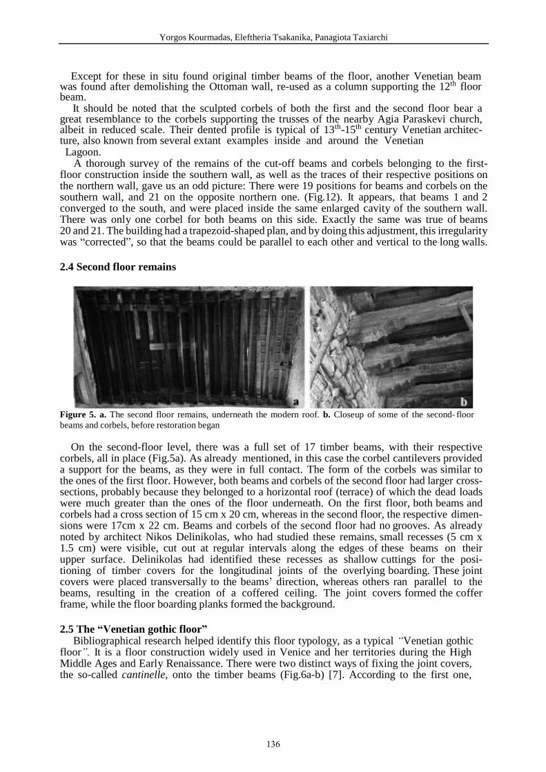
Yorgos Kourmadas, Eleftheria Tsakanika, Panagiota Taxiarchi
Except for these in situ found original timber beams of the floor, another Venetian beam was found after demolishing the Ottoman wall, re-used as a column supporting the 12th floor beam. It should be noted that the sculpted corbels of both the first and the second floor bear a great resemblance to the corbels supporting the trusses of the nearby Agia Paraskevi church, albeit in reduced scale. Their dented profile is typical of 13th-15th century Venetian architec-ture, also known from several extant examples inside and around the Venetian Lagoon.
A thorough survey of the remains of the cut-off beams and corbels belonging to the first-floor construction inside the southern wall, as well as the traces of their respective positions on the northern wall, gave us an odd picture: There were 19 positions for beams and corbels on the southern wall, and 21 on the opposite northern one. (Fig.12). It appears, that beams 1 and 2 converged to the south, and were placed inside the same enlarged cavity of the southern wall. There was only one corbel for both beams on this side. Exactly the same was true of beams 20 and 21. The building had a trapezoid-shaped plan, and by doing this adjustment, this irregularity was “corrected”, so that the beams could be parallel to each other and vertical to the long walls.
2.4 Second floor remains
Figure 5. a. The second floor remains, underneath the modern roof. b. Closeup of some of the second- floor beams and corbels, before restoration began
On the second-floor level, there was a full set of 17 timber beams, with their respective corbels, all in place (Fig.5a). As already mentioned, in this case the corbel cantilevers provided a support for the beams, as they were in full contact. The form of the corbels was similar to the ones of the first floor. However, both beams and corbels of the second floor had larger cross-sections, probably because they belonged to a horizontal roof (terrace) of which the dead loads were much greater than the ones of the floor underneath. On the first floor, both beams and corbels had a cross section of 15 cm x 20 cm, whereas in the second floor, the respective dimen-sions were 17cm x 22 cm. Beams and corbels of the second floor had no grooves. As already noted by architect Nikos Delinikolas, who had studied these remains, small recesses (5 cm x 1.5 cm) were visible, cut out at regular intervals along the edges of these beams on their upper surface. Delinikolas had identified these recesses as shallow cuttings for the posi-tioning of timber covers for the longitudinal joints of the overlying boarding. These joint covers were placed transversally to the beams’ direction, whereas others ran parallel to the beams, resulting in the creation of a coffered ceiling. The joint covers formed the coffer frame, while the floor boarding planks formed the background.
2.5 The “Venetian gothic floor” Bibliographical research helped identify this floor typology, as a typical “Venetian gothic floor”. It is a floor construction widely used in Venice and her territories during the High Middle Ages and Early Renaissance. There were two distinct ways of fixing the joint covers, the so-called cantinelle, onto the timber beams (Fig.6a-b) [7]. According to the first one,
136

prevalent approximately from 1300 to 1425 AD, cantinelle were directly nailed onto the beams’ upper surface. Boarding planks were then nailed onto the cantinelle. This resulted in the planks not being in contact with the beams themselves. The second technique, prevalent from about 1425 to 1550, saw the cantinelle inserted into recesses cut out on the beams’ upper edges. In this way, boarding planks were in full contact to the upper surface of the beams. According to literature, both techniques had simultaneously been used for an overlapping pe-riod of time, so they do not constitute a safe dating indication [7]. The second floor of the “Bailo building” was constructed according to the second technique, as the existing recesses indicate. Examination of the upper surfaces of the only two surviving first floor beams showed no sign of such recesses. Furthermore, re-examining the gap between the two surviving beams and their corbels, we were able to identify in both of them, remains of cantinelle nailed directly onto the upper surface of the corbels (Fig.6c-d). It was thus proven that this floor was constructed according to the first technique, by directly nailing the cantinelle on the beams, and the boarding onto the cantinelle. The very few remnants of cantinelle found showed us the thickness of the planks used for the cantinelle (1.5 cm), and the dimensions of the coffers. What is more important, the puzzle of the gap between corbels and beams of the first floor was solved, proving that it was not a construction mistake as previously thought. A secondary lowered coffered ceiling, two coffers wide, had existed at this position, running parallel to the long walls of the rooms -an interesting decorative feature that offered plasticity (Fig.7b,11b).
Figure 6. Left: The two ways of fastening cantinelle and the boarding of the “gothic venetian floor” according to Menichelli and Scappin:a.Cantinelle nailed onto beams, b.Cantinelle placed inside cut-out recesses. Right: Examining the Cantinelle remains on the surviving corbels.c.The 1st beam corbel d. the 12th one.
Interestingly, one of the few surviving examples from Venice, where this exact same technique is used, is at the Doge’s Palace. The floor over the Sala del Piovego and underneath the Sala del Maggior Consiglio features a similar two leveled coffered ceiling, and the same gap between the corbels and the floor beams [8]. That floor in Venice has a documented construction date of 1340 AD. A still unpublished dendrochronological research of the “Bailo building” timbers, conducted by associate professor Tomasz Wazny at the University of Arizona, proved both floors and the timber lacings to be contemporary, and dated at the first half of the 14th century AD. The timber of both corbels and beams was Greek fir (abies cephalonica). So, it appears that in the remote Venetian colony of Negroponte, the forms and techniques used in the construction of this public building, were closely following the trends from the mother city, and actually from its most prominent contemporary building, the Doge’s Palace. Examining similar Venetian examples, we were able to identify the grooves on both cor-bels and beams of the first floor, as the positions where once the pettenelle were positioned. These are slightly inclined planks that seal the gap between each pair of beams and corbels. Furthermore, pettenelle were used as decorative surfaces, where heraldry symbols were typically painted. The pettenelle on both sides of the surviving two corbels, were obviously touching
137
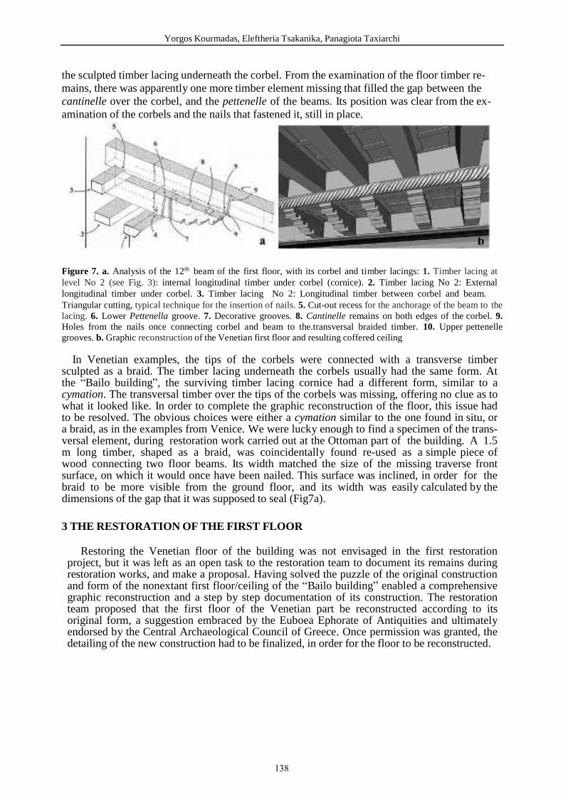
Yorgos Kourmadas, Eleftheria Tsakanika, Panagiota Taxiarchi
the sculpted timber lacing underneath the corbel. From the examination of the floor timber re-mains, there was apparently one more timber element missing that filled the gap between the cantinelle over the corbel, and the pettenelle of the beams. Its position was clear from the ex-amination of the corbels and the nails that fastened it, still in place.
Figure 7. a. Analysis of the 12th beam of the first floor, with its corbel and timber lacings: 1. Timber lacing at level No 2 (see Fig. 3): internal longitudinal timber under corbel (cornice). 2. Timber lacing No 2: External longitudinal timber under corbel. 3. Timber lacing No 2: Longitudinal timber between corbel and beam. Triangular cutting, typical technique for the insertion of nails. 5. Cut-out recess for the anchorage of the beam to the lacing. 6. Lower Pettenella groove. 7. Decorative grooves. 8. Cantinelle remains on both edges of the corbel. 9. Holes from the nails once connecting corbel and beam to the.transversal braided timber. 10. Upper pettenelle grooves. b. Graphic reconstruction of the Venetian first floor and resulting coffered ceiling
In Venetian examples, the tips of the corbels were connected with a transverse timber sculpted as a braid. The timber lacing underneath the corbels usually had the same form. At the “Bailo building”, the surviving timber lacing cornice had a different form, similar to a cymation. The transversal timber over the tips of the corbels was missing, offering no clue as to what it looked like. In order to complete the graphic reconstruction of the floor, this issue had to be resolved. The obvious choices were either a cymation similar to the one found in situ, or a braid, as in the examples from Venice. We were lucky enough to find a specimen of the trans-versal element, during restoration work carried out at the Ottoman part of the building. A 1.5 m long timber, shaped as a braid, was coincidentally found re-used as a simple piece of wood connecting two floor beams. Its width matched the size of the missing traverse front surface, on which it would once have been nailed. This surface was inclined, in order for the braid to be more visible from the ground floor, and its width was easily calculated by the dimensions of the gap that it was supposed to seal (Fig7a).
3 THE RESTORATION OF THE FIRST FLOOR
Restoring the Venetian floor of the building was not envisaged in the first restoration project, but it was left as an open task to the restoration team to document its remains during restoration works, and make a proposal. Having solved the puzzle of the original construction and form of the nonextant first floor/ceiling of the “Bailo building” enabled a comprehensive graphic reconstruction and a step by step documentation of its construction. The restoration team proposed that the first floor of the Venetian part be reconstructed according to its original form, a suggestion embraced by the Euboea Ephorate of Antiquities and ultimately endorsed by the Central Archaeological Council of Greece. Once permission was granted, the detailing of the new construction had to be finalized, in order for the floor to be reconstructed.
138

33.1 Restoration Prin iples and O je tives The main principles and objectives of the floor reconstruction project included:
Preserving as much of the scarce surviving original timber material as possible. Reconstructing the floor in its original form, by maintaining the original construction
technique. Securing that the resulting floor would be safe and compliant with actual structural
specifications, as the building was planned to become a public venue. Improving the overall seismic response of the building through the reconstruction of
the floor, enhancing its diaphragmatic action. Ensuring the floor’s durability against decay from mould and insects.
3.2 Assessment and reuse of the original timber elements An assessment of the two original timber beams had to be made, before they could be-deemed suitable for use. After visual examination, both beams were found to be free from woodworm infestation. However, they had suffered mass loss due to other reasons. The easternmost beam (the 1st one) had in the past been partially burned and lost part of its upper surface. Likewise, the northern end of the 12th beam, had very diminished dimensions due to mould decay. After the carbonised and decayed parts were removed respectively, thorough resistograph testing was carried out, that found the beams to be sound all through their mass. They were subsequently completed with new substitution parts from fir wood slices, screwed onto the original timbers. For the 12th beam, it was decided for extra security, that it be moved to the vacant westernmost position, where it would have to withstand half the loads than in its original one. However, its corbel and adjacent cornice were never moved, they remained and were conserved in situ (Fig.10a). It was decided that the other beam that had been reused in Ottoman times as a column be placed in its original position, under the new 12th beam, as an important element of the building’s construction history [Fig.11a].
3.3 New timber material It should be noted that in the 1990s the Greek Ministry of Culture had bought a large quantity of chestnut beams for use in the “Bailo building” restoration, a project that was afterwards shelved. What’s more, exact replicas of the corbels had been produced, again in chestnut. All this material was stockpiled for eventual later use. Once the timbers were examined, they were found to be of very good quality and in a good condition. Even though analysis showed the original floor timbers to be made of fir wood, it was decided to use them in the reconstruction, because of their enhanced structural strength, and most importantly, because of the great cost and delay that acquiring new timbers would involve. The structural model of the new floor was calculated by civil engineer Theodoros Palantzas, who found the new chestnut beams, with the same dimensions as the original ones, to be sufficient. The corbels, were, however found not to have the necessary length, in order to be inserted into the southern wall all the way to the external lacing timber. They were some 40cm shorter, and would not function as cantilevers, if used. It was thus decided to order new ones with the necessary length for the southern side of the floor, again made of chestnut wood. For the northern wall, that was anyway thinner, their size was ideal. The only adjustment to be made was that they were lacking the pettenelle grooves, that had to be carved out. For the planks of the boarding and the pettenelle and cantinelle, it was decided to buy fir timber, as the great width of the boards (30 cm), could not have been obtained from deciduous species. The missing parts of the timber lacings would be constructed of chestnut, as it is closer to the original oak, and more resistant to humid conditions. Finally, the restoration team decided that the decorative braid which was originally found to be made of juniper wood, would be carved in chestnut that is also a hard wood. All new timbers were double coated with a water-based fungicide and insecticide beforehand, as well as on the spot, when cutting was involved.
139
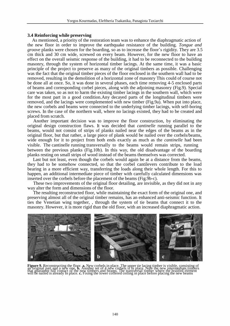
Yorgos Kourmadas, Eleftheria Tsakanika, Panagiota Taxiarchi
3.4 Reinforcing while preserving As mentioned, a priority of the restoration team was to enhance the diaphragmatic action of the new floor in order to improve the earthquake resistance of the building. Tongue and groove planks were chosen for the boarding, so as to increase the floor’s rigidity. They are 3.5 cm thick and 30 cm wide, screwed on every beam. However, for the new floor to have an effect on the overall seismic response of the building, it had to be reconnected to the building masonry, through the system of horizontal timber lacings. At the same time, it was a basic principle of the project to preserve as many of the original timbers as possible. Challenging was the fact that the original timber pieces of the floor enclosed in the southern wall had to be removed, resulting in the demolition of a horizontal zone of masonry This could of course not be done all at once. So, it was done in several phases, each time removing 4-5 enclosed parts of beams and corresponding corbel pieces, along with the adjoining masonry (Fig.9). Special care was taken, so as not to harm the existing timber lacings in the southern wall, which were for the most part in a good condition.Any decayed parts of the longitudinal timbers were removed, and the lacings were complemented with new timber (Fig.9a). When put into place, the new corbels and beams were connected to the underlying timber lacings, with self-boring screws. In the case of the northern wall, where no lacings existed, they had to be created and placed from scratch. Another important decision was to improve the floor construction, by eliminating the original design construction flaws. It was decided that cantinelle running parallel to the beams, would not consist of strips of planks nailed near the edges of the beams as in the original floor, but that rather, a large piece of plank would be nailed over the corbels/beams, wide enough for it to project from both ends exactly as much as the cantinelle had been visible. The cantinelle running transversally to the beams would remain strips, running between the previous planks (Fig.10b). In this way, the old disadvantage of the boarding planks resting on small strips of wood instead of the beams themselves was corrected. Last but not least, even though the corbels would again be at a distance from the beams, they had to be somehow connected, so that the corbel cantilevers contribute to the load bearing in a more efficient way, transferring the loads along their whole length. For this to happen, an additional intermediate piece of timber with carefully calculated dimensions was inserted over the corbels before the placement of the beams (Fig.9b-c). These two improvements of the original floor detailing, are invisible, as they did not in any way alter the form and dimensions of the floor. The resulting reconstructed floor, while maintaining the exact form of the original one, and preserving almost all of the original timber remains, has an enhanced anti-seismic function. It ties the Venetian wing together, , through the system of tie beams that connect it to the masonry. However, it is more rigid than the old floor, with an increased diaphragmatic action.
Figure 9. Reconstructing the floor. a. New corbels in place. The upper tie lacing timber is visible, consisting of an original part and a new one. b. Another set of 4 new corbels is in place. Note the new intermediate timbersthat guarantee full contact of the new timbers and beams. The transversal timber where the braided element will be nailed is already In place. c. Fixing the lower coffered ceiling in place before placing the new beams
140

The Venetian Floor of the “Bailo Building” in Chalcis, Greece: Deciphering its Lost Construction Details
Figure 10. a. The in situ remaining original 12th corbel and underlying cornice, with the new corbels and beams. The lower coffered ceiling between corbels and beams is already in place. Discernible is the original braid element, that was found reused in the Ottoman wing by chance. b. Constructing the coffered ceiling over the beams. The cantinelle running transversally to the beams are made of strips as original, whereas the ones parallel to the beams are made of planks projecting over the edges of the beams, ensuring full contact of floor boarding and beams. Note some tongue and groove boarding planks that have already been screwed into place
4 CONCLUSIONS As evidenced by the above described restoration process (documentation, analysis, as-sessment and reconstruction proposal) followed at the “Bailo building”, even when timber remains are scarce and evidence seems to be extremely little, it may be possible to discover the original structural system and architectural form, through a thorough constructional analysis combined with historical and bibliographical research. Since this investigation is usually not possible during the restoration study, it must be specified and assured as an indis-pensable part of the restoration works. The whole project has to be re-analysed and re- assessed in order to reach a solid base for the final restoration/reconstruction proposal. In the “Bailo building” restoration project, a lot of the most valuable information came to light during these works. Valuable information not only about the Venetian construction techniques used for the timber floors and ceilings, but moreover about their combination with the local timber lacing reinforcement system. In Venice, as almost everywhere in Italy, this intricate system, incorporated within the masonry, is largely absent. Timber beams encased in the walls were only used as supports for floor beams (bedding elements), and therefore, were not encircling and tying the buildings together. This system, used since prehistoric times in seismically active Greece [9], was adopted in a building of otherwise Venetian architecture, in order to improve its earthquake resistance. It is a very interesting example of cultural osmosis in building technology
Figure 11. a. The reconstructed floor. The Ottoman era support column made of a reused Venetian beam was put back into place, as an important testimony of the building’s construction history. b. Closeup of ceiling
141
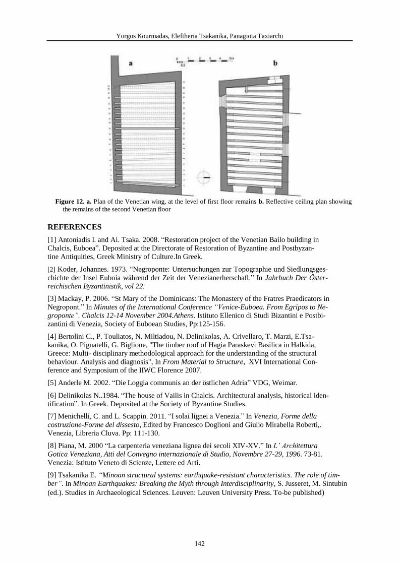
Yorgos Kourmadas, Eleftheria Tsakanika, Panagiota Taxiarchi
Figure 12. a. Plan of the Venetian wing, at the level of first floor remains b. Reflective ceiling plan showing the remains of the second Venetian floor
REFERENCES
[1] Antoniadis I. and Ai. Tsaka. 2008. “Restoration project of the Venetian Bailo building in Chalcis, Euboea”. Deposited at the Directorate of Restoration of Byzantine and Postbyzan-tine Antiquities, Greek Ministry of Culture.In Greek.
[2] Koder, Johannes. 1973. “Negroponte: Untersuchungen zur Topographie und Siedlungsges-chichte der Insel Euboia während der Zeit der Venezianerherschaft.” In Jahrbuch Der Öster-reichischen Byzantinistik, vol 22.
[3] Mackay, P. 2006. “St Mary of the Dominicans: The Monastery of the Fratres Praedicators in Negropont.” In Minutes of the International Conference “Venice-Euboea. From Egripos to Ne-groponte”. Chalcis 12-14 November 2004.Athens. Istituto Ellenico di Studi Bizantini e Postbi-zantini di Venezia, Society of Euboean Studies, Pp:125-156.
[4] Bertolini C., P. Touliatos, N. Miltiadou, N. Delinikolas, A. Crivellaro, T. Marzi, E.Tsa-kanika, O. Pignatelli, G. Biglione, "The timber roof of Hagia Paraskevi Basilica in Halkida, Greece: Multi- disciplinary methodological approach for the understanding of the structural behaviour. Analysis and diagnosis", In From Material to Structure, XVI International Con-ference and Symposium of the IIWC Florence 2007.
[5] Anderle M. 2002. “Die Loggia communis an der östlichen Adria” VDG, Weimar.
[6] Delinikolas N..1984. “The house of Vailis in Chalcis. Architectural analysis, historical iden-tification”. In Greek. Deposited at the Society of Byzantine Studies.
[7] Menichelli, C. and L. Scappin. 2011. “I solai lignei a Venezia.” In Venezia, Forme della costruzione-Forme del dissesto, Edited by Francesco Doglioni and Giulio Mirabella Roberti,. Venezia, Libreria Cluva. Pp: 111-130.
[8] Piana, M. 2000 “La carpenteria veneziana lignea dei secoli XIV-XV.” In L’ Architettura Gotica Veneziana, Atti del Convegno internazionale di Studio, Novembre 27-29, 1996. 73-81. Venezia: Ιstituto Veneto di Scienze, Lettere ed Arti.
[9] Tsakanika E. “Minoan structural systems: earthquake-resistant characteristics. The role of tim-ber”. In Minoan Earthquakes: Breaking the Myth through Interdisciplinarity, S. Jusseret, M. Sintubin (ed.). Studies in Archaeological Sciences. Leuven: Leuven University Press. To-be published)
142
STRUCTURAL AND ORNAMEN TAL USE OF TIMBER IN HAGIA TRIADA CHURCH, AYVALIK
OKUMU Ş Gökhan1, CABBAR Nurşah 2, ÖZTÜRK Merve 3, ALADAĞ Azime, EKİCİ Cansu, GÖKÇÜ Merve, KISAER Miray, GÖKÇE Fuat, ÖZGÖNÜL Nimet, ÖZÇAKIR
Özgün1Middle East Technical University, Faculty of Architecture,
Department of Architecture, Graduate Program in Conservation of Cultural Heritage
2-3Middle East Technical University, Faculty of Architecture, Department of Architecture, Graduate Program in Conservation of Cultural Heritage
Keywords: Co servatio , Ti er-Fra e Stru tural Syste , Hagia Triada Chur h, Ayvalık
A stra t
his pape has e e ged ithi the s ope of "Desig i A hite tu al Co se atio " ou se of METU, Depa t e t of A hite tu e, G aduate P og a i Co se atio of Cultu al He itage i the fall se este of . This pape ai s to e eal the a ious st u tu al a d o a e tal uses of ti e a d a al ze the o st u tio details of Hagia T iada Chu h. Hagia T iada, a th e tu G eek O thodo Chu h i
A alık as e a i ed.
Hagia T iada Chu h is lo ated i A alık hi h as a i po ta t G eek settle e t du i g th a d th e tu . The hu h as uilt i 4 as the last hu h o f hu hes settled i the to . It has a asili al pla ith th ee a es a d a galle floo a o e the a the lo ated i est. Co posite s ste
applied to the uildi g, sto e aso a d ti e f a e st u tu e is used togethe . Mai oute alls a d a the e e o st u ted ith the sto e aso hile the oof a d galle floo e e o st u ted
ith the ti e f a e. I additio , oof s t u tu e is a ied o olithi ti e olu s hi h di ide the a es a d the oof st u tu e is o e ed o a e ted ti e eili gs. Si e the hu h is ostl de olished, o st u tio te h i ues that ha e e a e ha a te isti s of ti e s ste a e o se ed i a detailed a .
The Hagia T iada Chu h efle ts the details of afts a ship, ti e o st u tio s ste a d te h i ues, ate ial usage a d a tisti featu es of its pe iod. This is e i po ta t i te s of do u e tatio e ause all the i fo atio o ti e o st u tio te h i ue of its pe iod is gathe ed
ith detailed e a i atio a d do u e tatio . The efo e, the e a i atio a d do u e tatio of the uildi g gai s o e i po ta e to o se e it a d t a sfe i it to futu e ge e atio s.
143

G. Okumuş, N. Cabbar, M. Öztürk
1 INTRODUCTION
This study and research has emerged within the scope of "Design in Architectural Conservation" course of METU, Department of Architecture, Graduate Program in Conservation of Cultural Heritage in the fall semester of 2017. This course is conducted by Inst. Dr. Fuat Gökçe, Inst. Dr. Nimet Özgönül and Ress. Asst. Özgün Özçakır. The course was realized with the participation of Azime Aladag, Nurşah Cabbar, Cansu Ekici, Merve Gökçü, Miray Kıser, Gökhan Okumuş and Merve Öztürk.
The purpose in this studio work1; to define conservation / repair interventions and designing conservation projects for an architectural heritage by understanding, interpreting and evaluating what is done. Hagia Triada, a 19th century Greek Orthodox Church in Ayvalık was examined.
In the scope of this paper a review of the use of timber material and construction techniques from the analysis of studio work for the Hagia Triada Church was compiled and interpreted. Hagia Triada is located in Ayvalik; which is an important Greek settlement, especially during 18th and 19th century, in Ottoman Era. Hagia Triada is the last built Church, among the 11 Churches in Ayvalık, dated to 1846. The asset represents the artistic and technical specialties of its time and by embodying a wide variety of the usage of timber it is distinctive in comparison with the other churches in Ayvalık.
This paper aims to put forth the outcomes of the survey done among the Church and its context. Structural and material problems in the building which have not been used for many years caused great damage to the structure. In this case, the structural state and the construction technique of building could be analyzed in detail.
1.1 General Aspects of Ayvalik
Ayvalık is a coastal settlement in Balıkesir province which shows an integrity with the island set situated at the west part of inner sea of Mtylene (Lesbos) and northern part of Aegean. The history of this region is dating back to antique period but Ayvalık became significant in 18th and 19th century due to the olive and olive oil production. This particular situation was enhanced also by being a coast city.
Ayvalık is located linearly in north-south direction throughout the sea shore. This linearity is formed by virtue of the natural boundaries in east and west. By being a port city its commercial and industrial center became the core of the settlement. This core is constituted by several shops, stores and factories and it is surrounded by residential areas. On the periphery of the settlement, olive groves and forests are located.(Figure 3)
The other major character of the city was its demographic structure. The population living in Ayvalık was mostly Greek speaking Christians under Ottoman rule. This strongly affected the physical aspects of the city.
According to Psarros (Figure 1), development of Ayvalık is directly related to Churches. A church creates the center of a neighborhood. Considering Psarros scheme representing Ayvalık’s urban development; around 1500’s the very first settlement emerged in the surrounding of Taxiarhis, which is known as the oldest church of Ayvalık but built up again in
1 The method of the survey consists of three stages. Firstly literately research about the Church and its settlement was gathered. Secondly, on site survey was done for ten days aiming to collect information about technical and spatial features of the Church, urban texture where it is situated and to understand the historical context with the relation to other churches. On the site survey, to attain a three dimensional model and measured drawing, the Church was scanned with laser scanner from forty two stations with a maximum of two centimeter lapse. Especially for architectural and system details sketches were done and hand measurements were taken. And finally all the outputs coming from first two stages were synthesized. These syntheses lead to document and evaluate Hagia Triada.
144

Structural And Ornamental Use Of Timber In Hagia Triada Church, Ayvalik
1844, at 1750’s the city had been expanding to north and south direction with four neighborhoods focusing to an another church. After the Foundation of Kydonies Academy in 1804 the prosperity accelerated and Ayvalık also became an education center. Up to 1821 three more neighborhoods were set already. Unfortunately the conflicts between Greek citizens and Ottoman rulers end up with evacuation and destruction of Ayvalık from 1821 to 1832. After the allowance to settle in Ayvalık in 1832, its growth again started. Four Churches and related neighborhoods were built between 1832 and 1850. The consequences of First World War and Turkish Independence War changed the social form of Anatolia entirely. In accordance with Treaty of Lausanne in 1923, the Greek and Turkish population exchange was carried thought by both country rulers. New settlers of Ayvalık were mainly the Turks once living in Mytilene and Macedonia. The population migrated to Ayvalık was lesser and also culturally different then the former residents so most of the buildings were unused or modified. On the other hand there wasn’t any dramatic change in the physical form of the city until today.
Figure 1. Urban Development of Ayvalık and the location of Churches (11: Hagia Triada Church)
1.2 General Aspects of Hagia Triada Church
Hagia Triada is one of the seven Churhes in Ayvalık that was survived until today. It located is between the residential areas and the forests at the periphery, very close to the south entrance of the city. (Figure 2-3) The church was built up in 1846. It is standing on a podium, at the center of a large courtyard which is inclined. Today the courtyard walls are decadent. The remains and some traces of walls are observed. The traces show that there were 2 entrances to the courtyard from the street. The main entrance was defined by a monumental bell tower which is no longer standing. The secondary entrance was at the south. Evidences also show that there were cisterns and graves at the courtyard. Some components of the courtyard like original pebble flooring and the fountain at the north can be seen today. It has a basilical plan consisting of three naves oriented in west-east axis. The central nave is wider than the east and west ones. Side naves and central nave are separated from each other by five timber columns each. Central nave’s floor level is lower than side naves on the other hand; its roof is fairly higher. In the east part there is a semicircle apse. Bema which is a special place for reverends is two steps higher than central
145
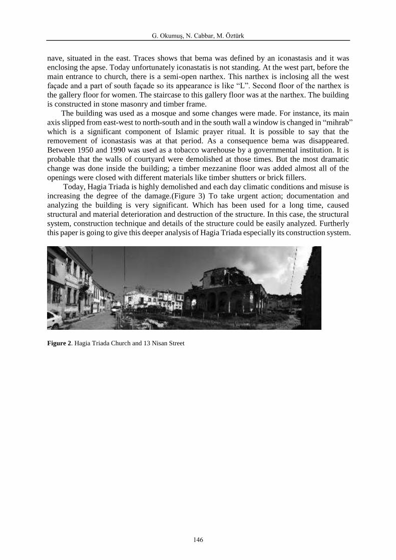
G. Okumuş, N. Cabbar, M. Öztürk
nave, situated in the east. Traces shows that bema was defined by an iconastasis and it was enclosing the apse. Today unfortunately iconastatis is not standing. At the west part, before the main entrance to church, there is a semi-open narthex. This narthex is inclosing all the west façade and a part of south façade so its appearance is like “L”. Second floor of the narthex is the gallery floor for women. The staircase to this gallery floor was at the narthex. The building is constructed in stone masonry and timber frame. The building was used as a mosque and some changes were made. For instance, its main axis slipped from east-west to north-south and in the south wall a window is changed in “mihrab” which is a significant component of Islamic prayer ritual. It is possible to say that the removement of iconastasis was at that period. As a consequence bema was disappeared. Between 1950 and 1990 was used as a tobacco warehouse by a governmental institution. It is probable that the walls of courtyard were demolished at those times. But the most dramatic change was done inside the building; a timber mezzanine floor was added almost all of the openings were closed with different materials like timber shutters or brick fillers. Today, Hagia Triada is highly demolished and each day climatic conditions and misuse is increasing the degree of the damage.(Figure 3) To take urgent action; documentation and analyzing the building is very significant. Which has been used for a long time, caused structural and material deterioration and destruction of the structure. In this case, the structural system, construction technique and details of the structure could be easily analyzed. Furtherly this paper is going to give this deeper analysis of Hagia Triada especially its construction system.
Figure 2. Hagia Triada Church and 13 Nisan Street
146
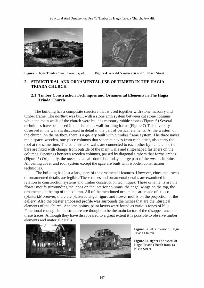
Structural And Ornamental Use Of Timber In Hagia Triada Church, Ayvalik
Figure 3 Hagia Triada Church Front Façade Figure 4. Ayvalık’s main axis and 13 Nisan Street
2 STRUCTURAL AND ORNAMENTAL USE OF TIMBER IN THE HAGIA TRIADA CHURCH
2.1 Timber Construction Techniques and Ornamental Elements in The Hagia Triada Church
The building has a composite structure that is used together with stone masonry and timber frame. The narthex was built with a stone arch system between cut stone columns while the main walls of the church were built as masonry rubble stones.(Figure 6) Several techniques have been used in the church as wall-forming forms.(Figure 7) This diversity observed in the walls is discussed in detail in the part of vertical elements. At the western of the church, on the narthex, there is a gallery built with a timber frame system. The three naves main space, wooden, one-piece columns that separate naves from each other, also carry the roof at the same time. The columns and walls are connected to each other by tie bar. The tie bars are fixed with clamps from outside of the main walls and ring-shaped fasteners on the columns. Openings between wooden columns, passed by diagonal timbers that forms arches. (Figure 5) Originally, the apse had a half-dome but today a large part of the apse is in ruins. All ceiling cover and roof system except the apse are built with wooden construction techniques. The building has lost a large part of the ornamental features. However, clues and traces of ornamented details are legible. These traces and ornamental details are examined in relation to construction systems and timber construction techniques. These ornaments are the flower motifs surrounding the icons on the interior columns, the angel wings on the top, the ornaments on the top of the column. All of the mentioned ornaments are made of stucco (plaster).Moreover, there are plastered angel figure and flower motifs on the projection of the gallery. Also the plaster embossed profile was surrounds the niches that are the liturgical elements of the church. At some points, paint layers were found as various tones of blue. Functional changes in the structure are thought to be the main factor of the disappearance of these traces. Although they have disappeared to a great extent it is possible to observe timber elements and material details.
Figure 5.(Left) Interior of Hagia Triada Church
Figure 6.(Right) The aspect of Hagia Triada Church from 13 Nisan Street
147
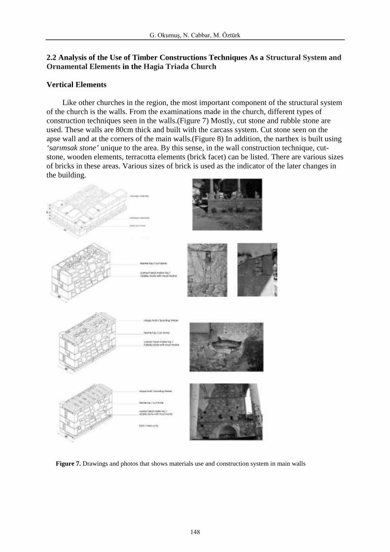
G. Okumuş, N. Cabbar, M. Öztürk
2.2 Analysis of the Use of Timber Constructions Techniques As a Structural System and Ornamental Elements in the Hagia Triada Church
Vertical Elements
Like other churches in the region, the most important component of the structural system of the church is the walls. From the examinations made in the church, different types of construction techniques seen in the walls.(Figure 7) Mostly, cut stone and rubble stone are used. These walls are 80cm thick and built with the carcass system. Cut stone seen on the apse wall and at the corners of the main walls.(Figure 8) In addition, the narthex is built using ‘sarımsak stone’ unique to the area. By this sense, in the wall construction technique, cut-stone, wooden elements, terracotta elements (brick facet) can be listed. There are various sizes of bricks in these areas. Various sizes of brick is used as the indicator of the later changes in the building.
Figure 7. Drawings and photos that shows materials use and construction system in main walls
148
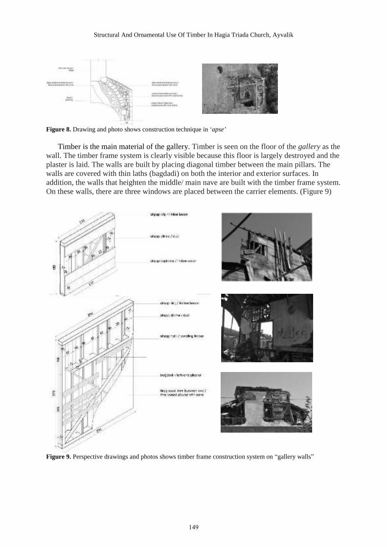
Structural And Ornamental Use Of Timber In Hagia Triada Church, Ayvalik
Figure 8. Drawing and photo shows construction technique in ‘apse’
Timber is the main material of the gallery. Timber is seen on the floor of the gallery as the wall. The timber frame system is clearly visible because this floor is largely destroyed and the plaster is laid. The walls are built by placing diagonal timber between the main pillars. The walls are covered with thin laths (bagdadi) on both the interior and exterior surfaces. In addition, the walls that heighten the middle/ main nave are built with the timber frame system. On these walls, there are three windows are placed between the carrier elements. (Figure 9)
Figure 9. Perspective drawings and photos shows timber frame construction system on “gallery walls”
149

G. Okumuş, N. Cabbar, M. Öztürk
Another vertical bearing element is the columns. According to structural systems and materials, there are two different columns in the building. The first is the columns made of cut stones (sarımsak stone) in the narthex.(Figure 10) In these columns, there are three parts, these are stone base, monolithic stone column and top stone capital the element connected each other with metal dowel/anchor. It is determined that there is a connection between the base of column, the body and the heading with metal elements. Another type is the timber columns.(Figure 11) Timber vertical carriers can be seen in two points in the building. There are mono block timber columns that are 8m length which separates the side naves from the middle nave. The column body is formed by the pounding laths on the main timber column. After that the pressure resistance was increased by wrapping the rope on it. This rope has 1-2 cm thickness and is wrapped from the bottom of the column to the top. The last layer of the column is plaster. This construction system is rare in terms of region and period. The base and the ornamental details made of plaster, is attached to the body with wooden fasteners and nails. The 10 columns created by this construction system provide the separation of the interior space. Eight of these columns are 40 cm in diameter.The diameter of the two columns in the Bema is 30 cm. There are no bases in these columns. This feature is also a sign that this area has an iconostasis that has been lost over time. Another timber column is used on the gallery floor. The structural difference between these two timber columns is a layer of rope. On the second is not used the rope. The 6 short vertical columns placed on the main walls are about 28 cm in diameter. These elements help to carry the roof of the gallery floor. The structure is supported by the tie bars between the columns. (Figure 12) The tie bars are fixed with clamps from outside the main wall. On the top of columns, there are ring-shaped fasteners. These tie bars work both in the north-south direction and in the east-west direction. The tie bars are also used in between stone columns in the narthex.
Figure 10. Drawins and photos shows the layers and construction system of the columns of‘Narthex’
150

Structural And Ornamental Use Of Timber In Hagia Triada Church, Ayvalik
Figure 11. Structural system of timber columns
Timber columns in the interior are decorated with ornamented column capital. Under this heading there is a timber base. A skeleton was created for the ornaments by nails were laid on the wooden base. In the interior timber columns, there are elliptical timber elements with pictures on them. On these elements, a notched texture was created for plastering and for keeping the ornaments.The timber columns and headings on them are connected to each other by using metal elements.
Figure 12. Drawings and photos shows that metal joint details and elements used in the narthex and interior columns.
151
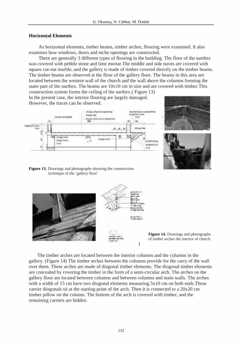
G. Okumuş, N. Cabbar, M. Öztürk
Horizontal Elements
As horizontal elements, timber beams, timber arches, flooring were examined. It also examines how windows, doors and niche openings are constructed. There are generally 3 different types of flooring in the building. The floor of the narthex was covered with pebble stone and lime mortar.The middle and side naves are covered with square cut-out marble, and the gallery is made of timber covered directly on the timber beams. The timber beams are observed at the floor of the gallery floor. The beams in this area are located between the western wall of the church and the wall above the columns forming the outer part of the narthex. The beams are 10x10 cm in size and are covered with timber.This construction system forms the ceiling of the narthex.( Figure 13) In the present case, the interior flooring are largely damaged. However, the traces can be observed.
Figure 13. Drawings and photographs showing the construction technique of the ‘gallery floor’
Figure 14. Drawings and photographs of timber arches the interior of church
The timber arches are located between the interior columns and the columns in the gallery. (Figure 14) The timber arches between the columns provide for the carry of the wall over them. These arches are made of diagonal timber elements. The diogonal timber elements are concealed by covering the timber in the form of a semi-circular arch. The arches on the gallery floor are located between columns and between columns and main walls. The arches with a width of 15 cm have two diogonal elements measuring 5x10 cm on both ends.These carrier diogonals sit at the starting point of the arch. Then it is connected to a 20x20 cm timber pillow on the column. The bottom of the arch is covered with timber, and the remaining carriers are hidden.
152
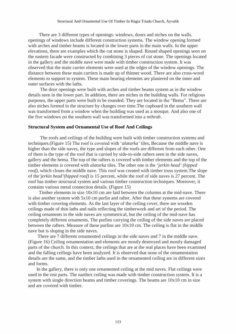
Structural And Ornamental Use Of Timber In Hagia Triada Church, Ayvalik
There are 3 different types of openings: windows, doors and niches on the walls. openings of windows include different construction systems. The window opening formed with arches and timber beams is located in the lower parts in the main walls. In the upper elevations, there are examples which the cut stone is shaped. Round shaped openings seen on the eastern facade were constructed by combining 3 pieces of cut stone. The openings located in the gallery and the middle nave were made with timber construction system. It was observed that the main carrier elements were used at the edges of the window openings. The distance between these main carriers is made up of thinner wood. There are also cross-wood elements to support to system. These main bearing elements are plastered on the inner and outer surfaces with the laths. The door openings were built with arches and timber beams system as in the window details seen in the lower part. In addition, there are niches in the building walls. For religious purposes, the upper parts were built to be rounded. They are located in the “Bema”. There are also niches formed in the structure by changes over time.The cupboard in the southern wall was transformed from a window when the building was used as a mosque. And also one of the five windows on the southern wall was transformed into a mihrab.
Structural System and Ornamental Use of Roof And Ceilings
The roofs and ceilings of the building were built with timber construction systems and techniques.(Figure 15) The roof is covered with ‘alaturka’ tiles. Because the middle nave is higher than the side naves, the type and slopes of the roofs are different from each other. One of them is the type of the roof that is carried by side-to-side rafters seen in the side naves, gallery and the bema. The top of the rafters is covered with timber elements and the top of the timber elements is covered with alaturka tiles. The other one is the ‘jerkin head’ (hipped roof), which closes the middle nave. This roof was created with timber truss system.The slope of the‘jerkin head’(hipped roof) is 15 percent, while the roof of side naves is 27 percent. The roof has timber structural system and various timber construction techniques. Moreover, it contains various metal connection details. (Figure 15) Timber elements in size 10x10 cm are laid between the columns at the mid-nave. There is also another system with 5x10 cm purlin and rafter. After that these systems are covered with timber covering elements. As the last layer of the ceiling cover, there are wooden ceilings made of thin laths and nails reflecting the timberwork and art of the period. The ceiling ornaments in the side naves are symmetrical, but the ceiling of the mid-nave has completely different ornaments. The purlins carrying the ceiling of the side naves are placed between the rafters. Measure of these purlins are 10x10 cm. The ceiling is flat in the middle nave but is sloping in the side naves. There are 7 different ornamented ceilings in the side naves and 7 in the middle nave. (Figure 16) Ceiling ornamentation and elements are mostly destroyed and mostly damaged parts of the church. In this context, the ceilings that are at the real places have been examined and the falling ceilings have been analyzed. It is observed that none of the ornamentation details are the same, and the timber laths used in the ornamented ceiling are in different sizes and forms. In the gallery, there is only one ornamented ceiling at the mid naves. Flat ceilings were used in the rest parts. The narthex ceiling was made with timber construction system. It is a system with single direction beams and timber coverings. The beams are 10x10 cm in size and are covered with timber.
153
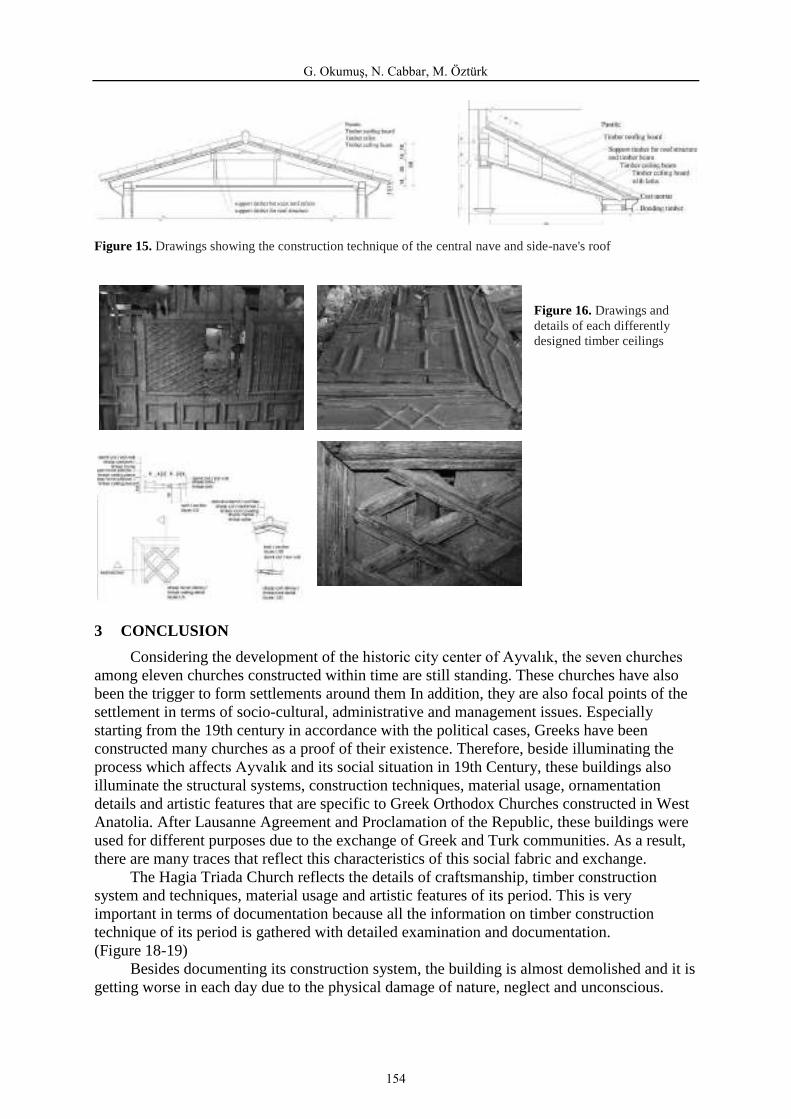
G. Okumuş, N. Cabbar, M. Öztürk
Figure 15. Drawings showing the construction technique of the central nave and side-nave's roof
Figure 16. Drawings and details of each differently designed timber ceilings
3 CONCLUSION
Considering the development of the historic city center of Ayvalık, the seven churches among eleven churches constructed within time are still standing. These churches have also been the trigger to form settlements around them In addition, they are also focal points of the settlement in terms of socio-cultural, administrative and management issues. Especially starting from the 19th century in accordance with the political cases, Greeks have been constructed many churches as a proof of their existence. Therefore, beside illuminating the process which affects Ayvalık and its social situation in 19th Century, these buildings also illuminate the structural systems, construction techniques, material usage, ornamentation details and artistic features that are specific to Greek Orthodox Churches constructed in West Anatolia. After Lausanne Agreement and Proclamation of the Republic, these buildings were used for different purposes due to the exchange of Greek and Turk communities. As a result, there are many traces that reflect this characteristics of this social fabric and exchange. The Hagia Triada Church reflects the details of craftsmanship, timber construction system and techniques, material usage and artistic features of its period. This is very important in terms of documentation because all the information on timber construction technique of its period is gathered with detailed examination and documentation. (Figure 18-19) Besides documenting its construction system, the building is almost demolished and it is getting worse in each day due to the physical damage of nature, neglect and unconscious.
154

Structural And Ornamental Use Of Timber In Hagia Triada Church, Ayvalik
Therefore, the examination and documentation of the building gains more importance to conserve it and transfer in it to future generations.
Figure 17. Section of construction system describing the structural system and construction techniques
1
2
3
4
6 5 Figure 18. 3D model drawings describing the structural system and construction technique of the Hagia Triada Church (1. Main walls of main space and narthex: pink and yellow ‘sarımsak stone’ 2. Construction and addition of monolithic timber columns 3. Construction of the columns system 4. Construction of the gallery flooring 5. Construction of the gallery floor with ‘timber frame walls’ 6.Construction of the central nave (main space) and side-nave's roof.)
155
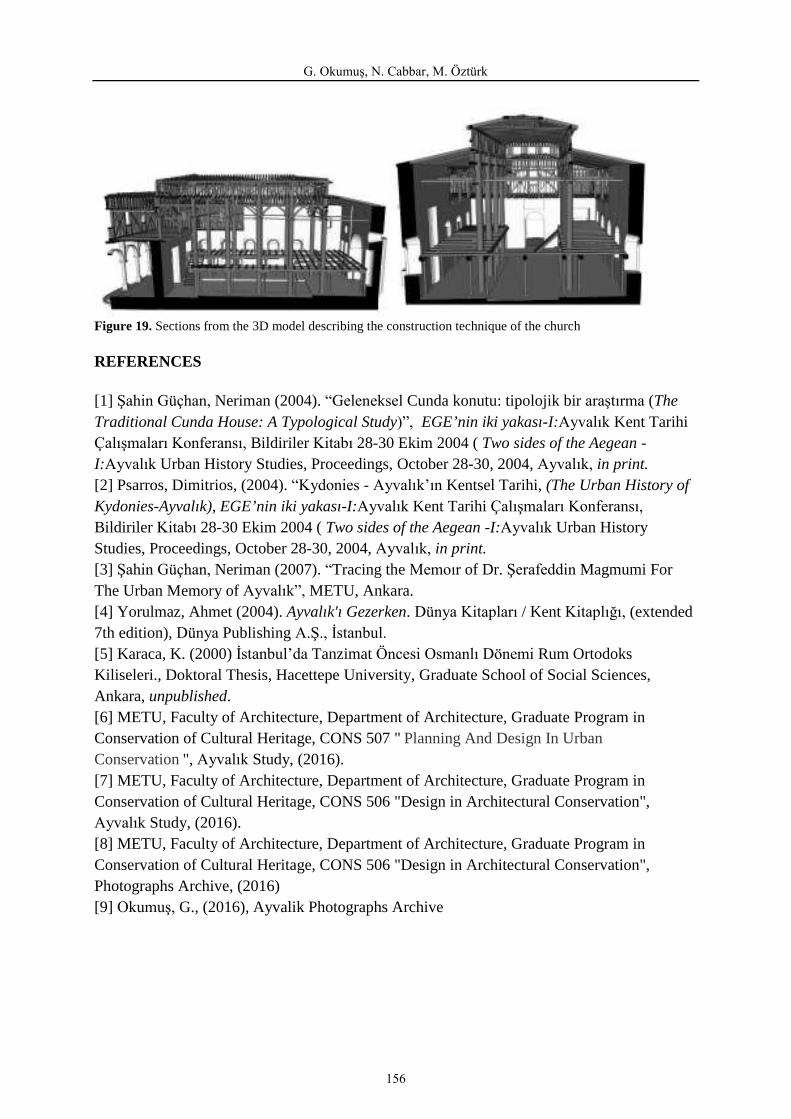
G. Okumuş, N. Cabbar, M. Öztürk
Figure 19. Sections from the 3D model describing the construction technique of the church
REFERENCES
[1] Şahin Güçhan, Neriman (2004). “Geleneksel Cunda konutu: tipolojik bir araştırma (The Traditional Cunda House: A Typological Study)”, EGE’nin iki yakası-I:Ayvalık Kent Tarihi Çalışmaları Konferansı, Bildiriler Kitabı 28-30 Ekim 2004 ( Two sides of the Aegean -I:Ayvalık Urban History Studies, Proceedings, October 28-30, 2004, Ayvalık, in print. [2] Psarros, Dimitrios, (2004). “Kydonies - Ayvalık’ın Kentsel Tarihi, (The Urban History of Kydonies-Ayvalık), EGE’nin iki yakası-I:Ayvalık Kent Tarihi Çalışmaları Konferansı, Bildiriler Kitabı 28-30 Ekim 2004 ( Two sides of the Aegean -I:Ayvalık Urban History Studies, Proceedings, October 28-30, 2004, Ayvalık, in print. [3] Şahin Güçhan, Neriman (2007). “Tracing the Memoır of Dr. Şerafeddin Magmumi For The Urban Memory of Ayvalık”, METU, Ankara. [4] Yorulmaz, Ahmet (2004). Ayvalık'ı Gezerken. Dünya Kitapları / Kent Kitaplığı, (extended 7th edition), Dünya Publishing A.Ş., İstanbul. [5] Karaca, K. (2000) İstanbul’da Tanzimat Öncesi Osmanlı Dönemi Rum Ortodoks Kiliseleri., Doktoral Thesis, Hacettepe University, Graduate School of Social Sciences, Ankara, unpublished. [6] METU, Faculty of Architecture, Department of Architecture, Graduate Program in Conservation of Cultural Heritage, CONS 507 " Planning And Design In Urban Conservation ", Ayvalık Study, (2016). [7] METU, Faculty of Architecture, Department of Architecture, Graduate Program in Conservation of Cultural Heritage, CONS 506 "Design in Architectural Conservation", Ayvalık Study, (2016). [8] METU, Faculty of Architecture, Department of Architecture, Graduate Program in Conservation of Cultural Heritage, CONS 506 "Design in Architectural Conservation", Photographs Archive, (2016) [9] Okumuş, G., (2016), Ayvalik Photographs Archive
156