proceedings - rochester institute of technologyedge.rit.edu/.../p16102_technical_paper.docx · web...
TRANSCRIPT
Multidisciplinary Senior Design ConferenceKate Gleason College of EngineeringRochester Institute of TechnologyRochester, New York 14623
Project Number: P16102
DEPLOYABLE CUBESAT SOLAR ARRAYS USING NOVEL FABRICATION TECHNIQUES FOR MASS SAVINGS AND COMPONENT REDUCTION
Paul CurtinMechanical Engineering
Anthony HennigMechanical Engineering
Robert MastiMechanical Engineering
Tristian McRaeMechanical Engineering
Abstract
This paper details the development of a 1U CubeSat frame to help provide enhanced capabilities for an on-
campus Space Exploration Research Group. This novel CubeSat frame design features printed ULTEM-9085
elements that provide strength, weight savings, and part count reductions, decreased cost, and enhanced reliability,
while adding the functionality of a deployable three face solar array by integrating hinge and stopper elements
directly into the frame. The final deployable features 2 faces that can swing into line with a third, maximizing the
solar cell area while keeping with the requirements for a 1U CubeSat. Machined aluminum rails provided structural
rigidity and compliance with the CubeSat Launch Requirements, while a lower printed ULTEM plate also served as
a platform for a nichrome hot knife and standoffs to encourage better thermal cutting of a nylon retention line while
also keeping the bottom face mostly opened for scientific payloads. Ultimately, this system provided a considerable
mass benefit for capability growth (180 grams for frame and deployable elements), demonstrated reliance and
functionality and high temperature extremes (-80 to 80 Centigrade), met launch requirements for loading and
vibration, and was responsive to a deployment command (reaction in sub 1 second). Future work would look at
scaling the capabilities of this system to 2U or 3U or adding more deployable sections.
Copyright © 2016 Rochester Institute of Technology

Proceedings of the Multidisciplinary Senior Design Conference Page 2
IntroductionRochester Institute of Technology’s new Space Exploration (SPEX) student-faculty research group was created in 2014 with the goal of bringing RIT into the field of CubeSat construction and experimentation. CubeSats are small vehicles used by industry, government, and universities to enable small scale experimentation with space systems. The Multidisciplinary Senior Design program of the Kate Gleason College of Engineering of RIT allows senior engineering students to contribute to a field, work on a project, or develop a technology capability for a group or customer on campus or in industry.
CubeSats are a low-cost method for performing small scale experiments in space at the picosatellite scale (10cmx10cmx10cm for 1U to 10cmx10cmx30cm for 3U). However, with their small size comes an even smaller surface area in which to collect solar energy (the typical approximation for CubeSats is one watt-hour per side per orbit). [1] CubeSat deployable solar arrays are available for purchase, however they are too expensive to be of use to RIT SPEX. Additionally, the inclusion of a deployable solar array adds a large number of components to the fabrication process and also increases the probability of failure for the entirety of the mission.
The objective is to create a deployable solar array for use in a 1U CubeSat capable of integrating with a general CubeSat bus while supplying the necessary power to subsystems for both the pre-deployed start-up phase and mission phase. It must also be capable of reliably deploying after enduring the launch conditions described in the CubeSat Launch Initiative and P-POD User Guides, be inexpensive to manufacture in comparison to similar systems, and be less complex than similar systems. Additionally, it must also deal with detumble before deployment as seen in the bat chart in Figure 1.
Space Operating Environment and Launch RequirementsWith CubeSats, design factors come from policies, launch services requirements, and space operating environmental factors. As per LSP-REQ-317.01 Revision B, this CubeSat frame was designed to meet Sinusoidal Vibration, Thermal Cycling, Thermal Bake out, Shock, and Random Vibration tests that were outlined in that document for launch. [2] Additionally, the CubeSat Design Specification, Revision 13, from was used to define the external dimensions of the 1U CubeSat (Section 1-1U CubeSat Design Specification), mass and inertia requirements
(Section 3 to Section 4), and provide a general acceptance checklist (Section 1-1U CubeSat Acceptance Checklist). [3] A baseline hypothetical payload was also designed of a mass and thermal analog to better refine vibration, loading and thermal tests.
Design ProcessThe Multidisciplinary Senior Design Process program of RIT’s Kate Gleason College of Engineering provided the student engineers with two fifteen week semesters to design and develop the systems architecture for the CubeSat frame. In general, the process went through a problem definition phase, systems design, subsystem design, detailed design, build and test prep, integrated build and test, and ultimately final testing and deliverables. Over the course of the year, the development was defined, built and prototyped using low-cost high-speed ABS additive manufacturing, then shifting over to finalized machining and industrial quality printing for the final flight ready hardware.
Initial direction came from the external faculty customer, and launch requirements. Benchmarking was made against industry standards such as the Clyde Space Design standard and other conceptual deployable solar cells. Early during the design process, the use of additive manufacturing to integrate elements of the hinge design was realized looking through industry research such as Fluitt’s work at Calpoly San Luis on the feasibility of 3d printed materials for CubeSat missions and the mechanical design elements of CAPE2. [4] [5]
Project P12015
Figure 1: Conceptual Use Case Bat Chart
Proceedings of the Multi-Disciplinary Senior Design Conference Page 3
From this review, a basic structure of four rails made of hard anodized aluminum would form the rails, with an additive manufactured hot plate with 70Ω/foot single loop nichrome coils to heat and break nylon fishing line retaining wires, a hub plate with integrated with hinges and stops such that two deployable plates could be attached to it. On the hot plate, there are also two standoffs to ensure the heat generated by the nichrome loops only broke the retaining line that were to be also printed out.
A great deal of time was spent on material selection for the additive manufacturing elements. Starting with Fluitt’s work on additive manufacturing for spaceflight, common printable materials like ABS and PLA are not acceptable for flight. [4] Then, carbon fiber nylon composite was explored for additive manufacturing, but the nature of the nylon matrix/binder to outgas prevented that from being used. [6] Ultimately, ULTEM-9085, which is available to print through high end industrial machines, was ideal to be used for this application, due to its high strength, high thermal resistance, dampening characteristics which indicated it could survive random, sinusoidal, and loading vibrations. [7]
Prototype I & Prototype IIInitial systems were designed within the first fifteen week period of the course (Figure 4), and printed out at the end of that first course and throughout the beginning of the next fifteen week period (Figure 2).
From these mechanical designs, structural ribs were added to a variety of components to increase their physical strength and simulated resistance to vibration loading. It was identified that with everything made out of ABS plastic, the weakest parts were the hub plate with the hinge elements, and the hot plate, which retained all the rails together at the bottom. Additionally, initial testing of the deployment mechanisms showed that the sharp angles used in the
retaining wire path would impinge the retainer line, leading to a redesign of the
Product 0Product 0 featured full metal rails to near specification from the CubeSat standard to demonstrate that the final printing of the CubeSat would meet the needed specifications for flight and the customer requirements, as well as testing the fabrication
procedures (Figure 3). Here, the hinge was further developed to ensure greater reliability and more strength.
Copyright © 2016 Rochester Institute of Technology
Figure 4: Prototype I CAD Model (Solidworks)
Figure 2: ABS Print of Prototype II, for Structural and Deployment Design
Figure 3: Product 0 Development

Proceedings of the Multidisciplinary Senior Design Conference Page 4
Product I (Final Product)
The Product I featured the first set of Ultem 9085 components supplied from Stratasys Direct Manufacturing and integrated with the frame elements. A mass analog was developed (weighing 915 grams), that also had the cross sectional area of the Pumpkin CubeSat PCB Specification (Figure 5). [8] and added mass to increase the rotational inertia components of the analog. This final frame with added hardware weighed in at approximately 1.2 kg, well within the CubeSat Standard, and the frame itself weighed approximately 180 grams (include rail elements, Ultem parts, deployable mechanism, but not solar panels or mass analog). When deployed, the CubeSat could produce upwards of 3U faces of deployment towards the sun, increasing the power capabilities of
1U CubeSats substantially (Figure 6).
Product IIProduct II demonstrated the final revision of the CubeSat frame, using curved elements to suspend the retention lines, notches on the end of the case for tensioning, and taller standoffs to prevent nichrome wire breakage during testing. Tan parts indicated fully complete structure assembly parts, and black parts were the deployable structure upon which solar cells would be stowed (Figure 7). The final revision required some finishing to ensure tolerance fitting and full 180 degree deployment of the solar array elements (Figure 8).
Figure 7: Final CubeSat Frame
Figure 8: Final Deployed CubeSat Design (No mass analog installed)
Subsystems and Their FabricationThe final CubeSat specification features three major subsystems used in conjunction: The Structural Subsystem, the Deployable Subsystem, and the Deployment Mechanism Subsystem. To help best approximate the actual mass of the system, acrylic
Project P12015
Figure 5: Deployed Product I
Figure 6: Product I Deployed with Mass Analog (915 grams, Meeting Pumpkin PCB Cross Section)

Proceedings of the Multi-Disciplinary Senior Design Conference Page 5
solar panels with analogous mass were developed (approximately 20 grams made to the NanoPower solar cell specification) as well as a mass analog made with the outline of the Pumpkin CubeSat Solar Panel PCB layout.Structural Subsystem
The structural subsystem was designed to the CubeSat standard with anodized aluminum rails, mounting points for two NanoPower solar cells holding the sides together and two plates on the top and bottom to keep all systems square. Instead of relying on a typical skin frame for CubeSats, the structural system is primarily skeletal and allows for simple manufacture and assembly ( Figure 9). In the end of the rail assembly, there are two deployment springs and two internal deployment switch plungers as per the CubeSat standard.
Deployable Subsystem
The Deployable Subsystem features two frame elements with solar panels (sans Magnetorquers) and attached to the hub plate, the main printed connector with both the hinge, shaft, and spring for deployment.[9] The Hub Plate has a single stainless steel shaft in the middle (2 mm in diameter), with torsional springs (0.05 inch-pounds) to push the deployable solar cell assemblies into place ( Figure 10).
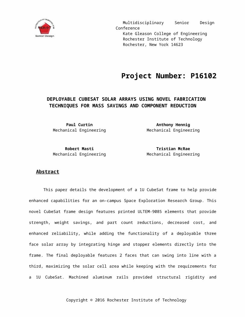
Deployment Mechanism SubsystemThe Deployment Mechanism was two hot knives set up with a long nylon 10 pound fishing line path using 70 ohm/feet single coil around the line. [10] The deployment mechanism was set up such that one hot knife could deploy both cells, but a redundant knife could deploy the other side ( Figure 11).
Copyright © 2016 Rochester Institute of Technology
Figure 9: Structural Subsystem with Aluminum Rails, ULTEM 9085 Hot and Hub Plates and Static Solar Cells
Figure 10: Deployable System with ULTEM Printed Rails and Moving Solar Panels, with one in stowed and one in deployed position. Please note that the hub plate (plate with large x in the middle) is represented twice in both this and Figure 9.

Proceedings of the Multidisciplinary Senior Design Conference Page 6
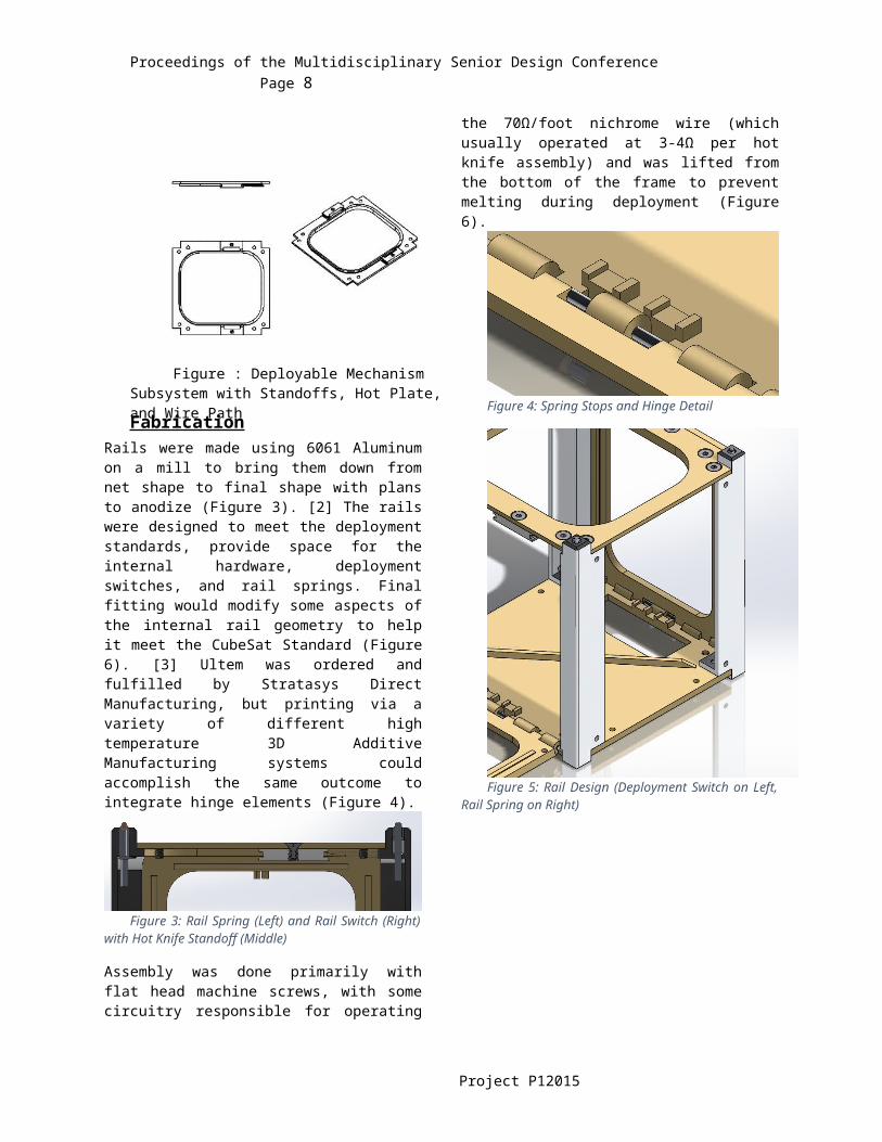
FabricationRails were made using 6061 Aluminum on a mill to bring them down from net shape to final shape with plans to anodize (Figure 12). [2] The rails were designed to meet the deployment standards, provide space for the internal hardware, deployment switches, and rail springs. Final fitting would modify some aspects of the internal rail geometry to help it meet the CubeSat Standard (Figure 15). [3] Ultem was ordered and fulfilled by Stratasys Direct Manufacturing, but printing via a variety of different high temperature 3D Additive Manufacturing systems could accomplish the same outcome to integrate hinge elements (Figure 13).
Figure 12: Rail Spring (Left) and Rail Switch (Right) with Hot Knife Standoff (Middle)
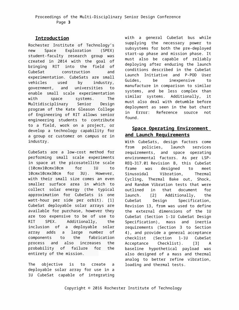
Assembly was done primarily with flat head machine screws, with some circuitry responsible for operating the 70Ω/foot nichrome wire (which usually operated at 3-4Ω per hot knife assembly) and was lifted from the bottom of the frame to prevent melting during deployment (Figure 15).
Figure 13: Spring Stops and Hinge Detail
Figure 14: Rail Design (Deployment Switch on Left, Rail Spring on Right)
Figure 15: Nichrome Hot Knife Assembly and Tensioning Lock
Testing
SimulationsSimulations have been consistently done within CubeSat to determine the physical characteristics of the flight ready frame. Using analytical solvers, such as COMSOL, the vibration Eigenfrequencies, thermal characteristics and expansion, and load experienced by the frame at a 6g acceleration.
Table Top Deployment TestThe simplest test ran, the table top deployment test ensured the system could repeatedly deploy during flight. By putting the CubeSat on its side, such that the
Project P12015
Figure 11: Deployable Mechanism Subsystem with Standoffs, Hot Plate, and Wire Path

Proceedings of the Multi-Disciplinary Senior Design Conference Page 7
panels rotated along the ground plane and there were no torques caused by gravity, and it was a better recreation of the space environment. To meet the needs for flight, and in light of the generally high failure rate of CubeSats to begin with, a success gate was put in place of 90%-95%, which was tested against during this process. Power draw measured was 5 volts at .2 Amps for 1 second (typically 0.5 sconds), requiring approximately 20 mAh to operate.
Fit TestingThe CubeSat Acceptance Checklist (Revision 13) was used to see if the flight ready frame could integrate with the PPOD. [3] Generally, some sanding, and very little material removal was necessary to fit the frame to the CubeSat dimensions. The Ultem and metal components were typically designed 0.1-0.5 mm too large, to accommodate for this process.
Sinusoidal VibrationA corresponding design project in the school was also designing a launch vehicle simulator operating on an average sweep of sinusoidal vibrations throughout the ranges experience during launch of the SpaceX Falcon 9 v1.0, Atlas V, and Delta IV. This test ran for one minute and was done three times, loading at six to eight gee’s in the rail direction, and vibrating from 10 to 100 hertz. No cracks were found, and the hot knife assemblies were undamaged.
Thermal Creep TestThe fishing line retention line was subjected to a variety of extreme temperatures to ensure that the line would keep during launch and detumble and still deploy when the command was given. One test involved placing the CubeSat in a conventional over between 50 and 80 degrees centigrade for nine hours. The other involved placing the CubeSat frame directly on dry ice at -80 degrees centigrade. For both, there was less than 0.1 mm change in solar cell movement because of change in the retention line and deployed easily (Figure 16
Figure 16: Thermal Bake Test
High Altitude Balloon TestTo test deployment at low pressure and low temperature, the hardware rode on the side of a High Altitude Balloon. Deployment happened two hours into mission elapsed time, at an altitude of approximately 60,000 feet. At this altitude, there was less than 10% atmosphere and low temperatures, and a deployment was recorded (Figure 17).
Figure 17: Picture from HAB Test
Time to RemoveThe frame was disassembled quickly to determine how efficiently the internal payloads could be removed by a support staff on the ground. This involved just using the hand tools used to put the system together and was to benefit the student groups who would inherit the project next. This also revealed that compared to benchmarked solutions, the total large part count of 10 (6 ULTEM and 4 Machined Rails) provided a great deal of benefit in design, execution, and assembly.
Engineering Test ResultsFrom the previous tests, the following performance characteristics were determined (Table 2: PerformanceCharacteristics ).
In comparison to benchmarked solutions, this system features the following assembly characteristics (Table1: Assembly Characteristics).
ULTEM-9085 Printed Parts 1 Hub Plate1 Hot Plate2 Deployable Wings2 Hot Knife Standoffs
Machined Elements 4 Rails, 2 Deployment Switches
Purchased Elements Springs, Pins, Deployment, Nichrome, Etc.
Manufacture Time 20 hours
Copyright © 2016 Rochester Institute of Technology
Proceedings of the Multidisciplinary Senior Design Conference Page 8
Assembly Time 5 hoursTable 1: Assembly Characteristics
Undeployed Photovoltaic Area
100 cm2
Deployed Photovoltaic Area 300 cm2
System Mass 180 gramsAvailable Interior Space 96x95x89 mm
(Pumpkin CubeSat PCB Standard)
Exterior Protrusion Space 4 mmLaunch Rating Partial (Falcon
9v1, Atlas V, Delta IV)
Lowest Eigenfrequencies-Simulation
332 Hz394 Hz
Temperature Range -60 to 80 degrees Centigrade
Time from Command to Deploy
2 seconds
Center of Mass Change <1cmApproximate Cost (May 2016)
$500 USD
Time to Remove Internals 3 minutesTable 2: Performance Characteristics
Conclusions, Recommendations, and Final WorkThis final CubeSat design provides several advantages against current benchmarked solutions in the field.
Reduced Component Count Reduced Mass Reduced Cost Enhanced Capability Simplified Assembly and Fabrication Scalability
Ultimately, this CubeSat frame is nearly ready to be implemented in the field, with final design and testing to be done at full scale vibration, thermal-vacuum and off-gassing, and shock/loading tests. As it stands right now, it helps economically and efficiently implement a three face deployable assembly at a 1U CubeSat scale.
Currently, many 1U CubeSats do not feature deployable arrays due to the number of added parts, increased cost, and increased mass. By being able to provide this solution at the mass for typical Commercial-Off-The-Shelf frame designs, greater functionality, better science missions, and more
reliable power generation could be expected at the 1U scale. Future work would also include potentially scaling this system up for a four face deployable or seeing if it could be extended to also help 2U and 3U CubeSat frames. Final testing is still heavily desired, but preliminary work through this project indicate that this is a superior 1U CubeSat deployable solution.
References
Project P12015

Proceedings of the Multi-Disciplinary Senior Design Conference Page 9
[1] I. Vertat and A. Vobornik, "Efficient and Reliable Solar Panels for Small CubeSat Picosatellites," International Journal of Photoenergy, vol. 2014, 2014.
[2] A. Mitskevich, "Launch Services Program Program Level Dispenser and CubeSat Requirements Document," 14 January 2014. [Online]. Available: http://www.nasa.gov/pdf/627972main_LSP-REQ-317_01A.pdf. [Accessed September 2015].
[3] A. Mehrparvar, "CubeSat Design Specification," 20 February 2014. [Online]. Available: http://cubesat.org.cubesat.org/images/developers/cds_rev13_final2.pdf. [Accessed September 2015].
[4] D. Fluitt, "Feasibility Study into the Use of 3D Printed Materials in CubeSat Flight Missions," California Polytechnic State University, San Luis Obispo Aerospace Engineering, San Luis, 2012.
[5] A. Bajpayee, "Mechanical Design of CAPE2 – the second CubeSat being designed under the Cajun Advanced Picosatellite Experiment (CAPE)," 2010. [Online]. Available: http://mstl.atl.calpoly.edu/~bklofas/Presentations/DevelopersWorkshop2010/31_Bajpayee_CAPE2.pdf. [Accessed October 2015].
[6] 3DXTech, "Product Data Sheet-3DX Nano ESD," December 2014. [Online]. Available: http://www.3dxtech.com/content/3DXNano_ESD_PETG_Data_Sheet_v1.pdf. [Accessed November 2015].
[7] Stratasys Direct Manufacturing, "Stratasys Direct Manufacturing Builds the First 3D Printed Parts to Function on the Exterior of a Satellite," [Online]. Available: https://www.stratasysdirect.com/case-studies/nasa-3d-printed-satellite/. [Accessed December 2015].
[8] AWR, "CubeSat Kit PCB Specification A5," 26 September 2003. [Online]. Available: http://www.cubesatkit.com/docs/CSK_PCB_Spec-A5.pdf. [Accessed September 2015].
[9] GOM SPACE, "NanoPower Solar Panels P110 Series," 2016. [Online]. Available: http://gomspace.com/?p=products-p110. [Accessed November 2015].
[10] Jacobs Online, "Nichrome 60 Wire," 2016. [Online]. Available: http://jacobs-online.biz/nichrome_wire.htm. [Accessed November 2015].
Acknowledgements
The Senior Design Program of the Kate Gleason College of Engineering and our faculty guide Professor Edward Hanzlik ([email protected]) and customer Dr. Dorin Patru ([email protected]).
Special thanks to Boeing for supporting the development of this project through funds, and Stratasys Direct Manufacturing-Buffalo for providing free Ultem-9085 printed parts for use.
Copyright © 2016 Rochester Institute of Technology