proceedings work-in-progress session of lctes...
TRANSCRIPT

ProceedingsWork-in-Progress Session
of LCTES 2012
June 12-13, 2012Beijing, China
Edited by Jan Reineke
Message from the WiP Chair
Dear Colleagues:
Welcome to Beijing and to the Work-in-Progress (WiP) session of LCTES 2012. I ampleased to present to you six papers on WiP that describe innovative research contribu-tions in the broad field of languages, compilers, tools and theory for embedded systems.The six accepted papers were selected from nine submissions.
The purpose of the LCTES WiP session is to provide researchers in academia and industryan opportunity to discuss their research ideas and to gather feedback from the communityat large. Special thanks go to the Work-in-Progress Program Committee members Patri-cia Derler, Daniel Grund, Nan Guan, Claire Maiza, Hiren D. Patel, and Benny Akessonfor their good work in reviewing the submissions.
Jan ReinekeWork-in-Progress ChairLCTES 2012

Program Committee
Patricia Derler University of California, Berkeley, USADaniel Grund Saarland University, GermanyNan Guan Uppsala University, SwedenClaire Maiza Verimag, FranceHiren D. Patel University of Waterloo, CanadaJan Reineke Saarland University, GermanyBenny Akesson Eindhoven University of Technology, Netherlands

Table of Contents
Object Oriented Programming in C: A Case Study of TMS320C6418 1Tanin Afacan . . . . . . . . . . . . . . . . . . . . . . . . . . . . . . . . . . . . . .
Dynamic Code Generation: An Experiment on Matrix Multiplication 5Damien Courousse and Henri-Pierre Charles . . . . . . . . . . . . . . . . . . . . .
Static Analysis of Worst-Case Inter-Core Communication Latency in CMPswith 2D-Mesh NoC 9Yiqiang Ding and Wei Zhang . . . . . . . . . . . . . . . . . . . . . . . . . . . . .
Adaptable and Precise Worst Case Execution Time Estimation Tool 13Vladimir-Alexandru Paun and Bruno Monsuez . . . . . . . . . . . . . . . . . . .
WCET Estimation of Multi-Core Processors with the MSI Cache CoherencyProtocol 17Pradeep Subedi and Wei Zhang . . . . . . . . . . . . . . . . . . . . . . . . . . . .
Introducing Service-oriented Concepts into Reconfigurable MPSoC on FPGAfor Coarse-grained Parallelization 21Chao Wang, Li Xi, Peng Chen, Junneng Zhang, Xiaojing Feng and Xuehai Zhou

Object Oriented Programming in C:
A Case Study of TMS320C6418
Tanın Afacan
Aselsan A.Ş.
Ankara, Turkey [email protected]
Abstract
This paper presents an empirical study of the impact of Object
Oriented Programming Implementation in C on the memory and
execution time of a fixed-point Digital Signal Processor from
Texas Instruments; TMS320C6418 [1]. Actually, the object-
oriented approach introduces a significant performance penalty
compared to classical procedural programming. One can find the
studies of the object-oriented penalty on the system in terms of
execution time and memory allocation in the literature. Since, to
the author’s best knowledge the study of the overheads of Object
Oriented Programming implementation in C for the embedded
systems is not widely published in the literature. Besides, it is
possible to implement Object Oriented Design in a procedural
language. The basic Object Oriented Programming features can be
implemented in C such as creating objects, polymorphism, virtual
functions, sub-classing, and inheritance. The main contribution of
the paper is to bring further evidence that embedded system
software developers have to consider the complexity and
performance of Object Oriented Programming implementation in
C in the embedded system programming. The results of the
experiment show that Object Oriented Programming
implementation in C adds significant complexity to the system,
although it gives almost the same memory allocation and
performance results as Object Oriented Programming
implementation in an object-oriented language such as C++.
Keywords: Digital Signal Processor (DSP), Object Oriented Programming (OOP), C, Object Oriented Design, C++
1. Introduction
Object Oriented Programming (OOP) is a paradigm and methodology for software development and design [2] based upon the idea of breaking the complex software system down into its various objects, combining the data and the functions that operate on the designed entity. Even though the object-oriented approach is known to introduce a significant performance penalty compared to classical procedural programming [3], OOP has proved to be one of the major steps towards more productive and systematic software design [4]. In principle, any design could be realized without OOP methodology but in complex software projects the productivity and conceptual clarity of OOP typically far exceeds the traditional approaches [4]. Therefore, OOP has become very popular in the past years for software development and design.
As a consequence of the fast growing complexity and size of embedded systems, the requirements for embedded software development are changing [5]. The effort spent on developing the system becomes more important, compared to the per-unit cost of
the device. It should become clear that OOP is a proper methodology for digital signal processor (DSP) programming [4]. In addition, OOP is a good methodology in DSP research and development as well.
Besides that, in embedded systems, ANSI C is the most commonly used language for DSP programming [6]. C has the advantages of high availability of compilers for wide range target processors, a well-deserved reputation for run-time efficiency [7]. Therefore, the embedded system software developers have not been very eager to adapt new technologies; especially the language adoption was very slow. Nevertheless, OOP is both a general methodology and a way of thinking, and a tool for programming [4]. It is possible to design and write programs based on OOP ideas without any specific OOP language, but if you choose correct language, you will be rewarded with a straightforward design and an even easier implementation [8]. Therefore, OOP features can be implemented in any programming language, but some languages are more suitable and flexible than others. One effective disadvantage of present OOP languages is the reduction in performance because of the object formalism. However, optimizing compilers keep trying to minimize or eliminate the overheads of the object-oriented languages [5].
Since C is commonly used in micro-controllers and it is possible to implement OOP in C, most of the features of OOP can be implemented via some techniques in C.
The goal of the paper is to supply the empirical memory allocation and performance data, while the performance is usually the major concern [9], to help the embedded system software developers to consider OOP implementation in a procedural language such as C. The second goal of the paper is to discuss the effect of OOP implementation in C to the reliability of the embedded system software.
2. Experiment
The experiment is done on TMS320C6418 of a custom design board. TMS320C6418 is one of the new generation highest-performance processors. TMS320C6418 has the operating frequency of 500 MHz. “Optimization Level” option of the compiler is set to “None” and “Opt. Speed vs. Size” option of the compiler is set to “Size Critical”.
For the experiment, two designs are examined. First design is Debounce example; a toggle button for a microwave is modeled, which has the simple relations and simple implementation also short code length. Second design is Queue/Cached Queue example that has relatively complex relations, complex implementation and longer code length.
Figure 1 and Figure 2 show the sample UML class diagrams of Debounce and Queue/CachedQueue examples [7]. These designs
1
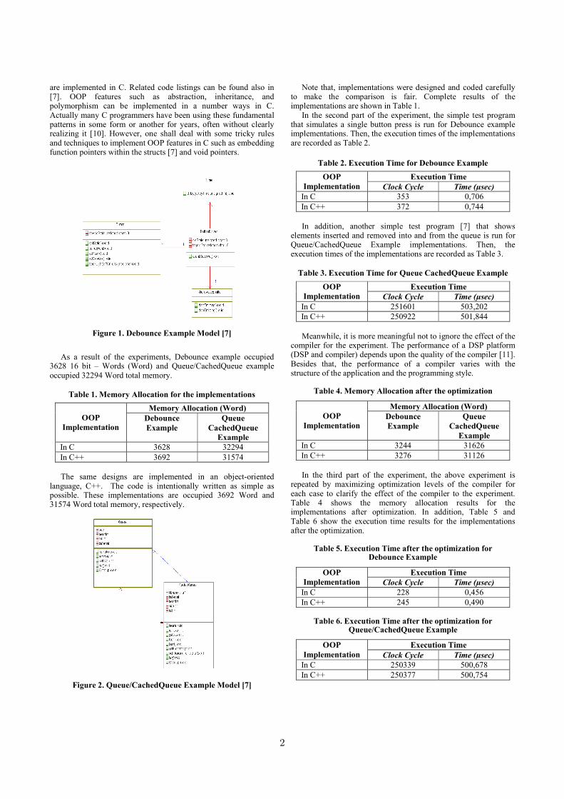
are implemented in C. Related code listings can be found also in [7]. OOP features such as abstraction, inheritance, and polymorphism can be implemented in a number ways in C. Actually many C programmers have been using these fundamental patterns in some form or another for years, often without clearly realizing it [10]. However, one shall deal with some tricky rules and techniques to implement OOP features in C such as embedding function pointers within the structs [7] and void pointers.
Figure 1. Debounce Example Model [7]
As a result of the experiments, Debounce example occupied
3628 16 bit – Words (Word) and Queue/CachedQueue example occupied 32294 Word total memory.
Table 1. Memory Allocation for the implementations
OOP
Implementation
Memory Allocation (Word)
Debounce
Example
Queue
CachedQueue
Example
In C 3628 32294
In C++ 3692 31574
The same designs are implemented in an object-oriented language, C++. The code is intentionally written as simple as possible. These implementations are occupied 3692 Word and 31574 Word total memory, respectively.
Figure 2. Queue/CachedQueue Example Model [7]
Note that, implementations were designed and coded carefully to make the comparison is fair. Complete results of the implementations are shown in Table 1.
In the second part of the experiment, the simple test program that simulates a single button press is run for Debounce example implementations. Then, the execution times of the implementations are recorded as Table 2.
Table 2. Execution Time for Debounce Example
OOP
Implementation
Execution Time
Clock Cycle Time (µsec)
In C 353 0,706
In C++ 372 0,744
In addition, another simple test program [7] that shows elements inserted and removed into and from the queue is run for Queue/CachedQueue Example implementations. Then, the execution times of the implementations are recorded as Table 3.
Table 3. Execution Time for Queue CachedQueue Example
OOP
Implementation
Execution Time
Clock Cycle Time (µsec)
In C 251601 503,202
In C++ 250922 501,844
Meanwhile, it is more meaningful not to ignore the effect of the compiler for the experiment. The performance of a DSP platform (DSP and compiler) depends upon the quality of the compiler [11]. Besides that, the performance of a compiler varies with the structure of the application and the programming style.
Table 4. Memory Allocation after the optimization
OOP
Implementation
Memory Allocation (Word)
Debounce
Example
Queue
CachedQueue
Example
In C 3244 31626
In C++ 3276 31126
In the third part of the experiment, the above experiment is
repeated by maximizing optimization levels of the compiler for each case to clarify the effect of the compiler to the experiment. Table 4 shows the memory allocation results for the implementations after optimization. In addition, Table 5 and Table 6 show the execution time results for the implementations after the optimization.
Table 5. Execution Time after the optimization for Debounce Example
OOP
Implementation
Execution Time
Clock Cycle Time (µsec)
In C 228 0,456
In C++ 245 0,490
Table 6. Execution Time after the optimization for Queue/CachedQueue Example
OOP
Implementation
Execution Time
Clock Cycle Time (µsec)
In C 250339 500,678
In C++ 250377 500,754
2

3. Discussion
Results of the experiment show that OOP implementation in C comes with almost same memory allocation, and execution time as OOP implementation in C++. With the above results, one might be convinced that OOP implementation in C shall be used in embedded systems because OOP in C does not have any overhead compared to OOP in C++. Actually, learning to use object-oriented techniques in C will not only make it easier to write your own objects in C, it will make it easier to understand the many toolkits and libraries that use these concepts [12]. However, Objects implemented in C are complex and the code becomes harder to debug and maintain. Even though, a tool is used to generate C code automatically from object-oriented design, implementations are hard to modify and maintain. The inclusion of object-oriented concepts into traditional languages sophisticated them, in that programmers had the flexibility to use or not to use the object-oriented extensions and benefits [13]. Although these languages became more complex, those extensions enabled programmers who had considerable experience with those traditional procedure languages to explore incrementally the different concepts provided by the object-oriented paradigm [13]. Nevertheless, when using a procedural language in OOP such as C, programmers had to exercise more discipline than when using a pure object-oriented language because it was too easy to deviate from sound object-oriented principles [13]. A powerful feature of object-oriented languages is the inheritance that allows classes to be arranged in a hierarchy and inherit behavior from classes above them. However, the danger in trying to force object-oriented concepts into a language that does not provide inheritance is that weird constructions may be produced, impairing software development, and jeopardizing the quality of the resulting software [13]. Specially, the polymorphism results in more errors and OOP is more difficult to recognize and understand, but again if a procedural language is used with an object-oriented design [15]. Actually, in embedded systems reliability is essential; indeed, embedded software may control a safety- or security-critical system where an error can have catastrophic consequences [8]. In addition, complexity is one of the important attribute of reliability and higher complexities increase the probability of error occurrences and decreases reliability of the software [17].
Alongside the recognized advantages, there seems to be a general feeling among procedural language programmers that object-oriented languages can result in inefficient code when compared with coding the same application in a procedural language. Like all such general knowledge, this need not be true; it all depends on which object-oriented language features you use and how you use them [14]. There are advantages of using an object-oriented language [16]. Object-oriented languages are able to distinguish an object’s internal, add user-defined types to augment the native types, create new types by importing or reusing the description of existing types and localizes responsibility for behavior. In addition, the change of approach that comes with object orientation provides improved debugging and maintenance.
Meanwhile, C++ offers the embedded programmer some striking advantages over C [16]. It can be used in place of C without change for most applications. Nevertheless, most running C code compiles and runs as C++ code. It extends C by including additional critical features that support object-oriented and generic programming. C++ also embraced generic programming using templates. It remedies some of C’s defects such as relying on the preprocessor, lack of type-safety, unrestricted casting. C++ also provides more scoping constructs and allows namespace scope and nested class scope, both unavailable in C.
As a point, C++ is a superset of C. This also demonstrates that moving to C++ is not an all or nothing event. Actually, the C
programmer is nearly a C++ programmer. Moving from C to C++ is relatively simple and does not require a break with existing C practice [16]. It is also possible to choose among the C++ features those that are useful in the application and ignore others at the beginning.
Therefore, in complex software, the use of OOP in an object-oriented language such as C++ will lead to cleaner architecture, a better reuse of code, and one will start to get comparable timings or even a significant gain over a code with written in C.
Specially, real-time embedded applications require the features for promoting reliability, maintainability, reusability, and other broad software engineering goals such as compile-time type checking, support for encapsulation and information hiding, namespace management parameterizable templates and object-oriented programming features [8].
In addition that the supporting evidence was found that programmers produce more maintainable code with an object-oriented language as C++ than a standard procedural language as C [15].
However, DSP manufactures announce new generation chips, almost every year, offering improved performance, reduced code size and more on-chip memory to help the developers to implement their embedded systems in object-oriented languages with less memory and performance overheads.
Finally, I also keep in my mind that the effect of the compiler for my experiment. The results of third part of the experiment did not change the direction of previous results. Furthermore, I believe that effect of the compiler do not change the conclusion. However, surprisingly I have had almost the same optimization ratios for the implementation in C and C++ in terms of execution time and memory allocation contrary to common belief of C++ programs are harder to optimize than programs written in languages like C [15]. It also shows that the sophisticated compilers try hard to optimize the performance of object-oriented languages. Optimization percentages of the compiler for the implementations are shown in Table 7 and Table 8, respectively. Note that, Debounce example has higher optimization ratios in terms of memory allocation and execution time because it has short code length and the simpler test program compared to Queue/CachedQueue example.
Table 7. Optimization Ratios for Debounce Example
OOP
Implementation
Optimization
Execution Time
Optimization
Total Memory
In C % 35,41 % 10,58
In C++ % 34,13 % 11,26
Table 8. Optimization Ratios for Queue/CachedQueue Example
OOP
Implementation
Optimization
Execution Time
Optimization
Total Memory
In C % 0,50 % 2,06
In C++ % 0,21 % 1,41
Future work would deal with other procedural languages in
order to generalize the discussion to OOP in procedural languages. In addition, future work would deal with power consumption as it is done with memory allocation and execution time.
3

4. Conclusion
According to the recent studies, it has been shown that OOP is a good methodology in embedded system research and development. ANSI C still is the most commonly used language for embedded system programming. Besides that, most of the features of OOP can be implemented via tricky techniques in C. However, OOP implementation in C adds the significant complexity to the implementations without any memory allocation and performance advantages. Nevertheless, the higher design and coding complexities increase the probability of error occurrences and decrease reliability of the software. Moreover, the new generation DSPs and compilers keep helping the developers to gain the advantages of object-oriented languages by improved performance, more on-chip memory, reduced and optimized code size. Consequently, there is no doubt that most new software systems will be object-oriented and will be implemented in object-oriented languages.
Acknowledgment
I would like to thank my colleagues and the anonymous reviewers for their helpful comments and suggestions.
References
[1] TMS320C64x/C64x+ DSP CPU and Instruction Set Reference Guide: August 2006.
[2] M. Karjalainen, 1992. Object-Oriented Programming of DSP processors: a case study of QuickC30, in International Conference on Acoustic, Speech and Signal Processing. ICASSP-92 Vol 5, 1992
[3] A. Chatzigeorgiou, 2003. Performance and power evaluation of C++ object-oriented programming in embedded processors, Information and Software Technology 45, p. 195-201.
[4] M. Karjalainen, 1990. DSP Software Integration by Object-Oriented Programming: a case study of QuickSig. IEEE ASSP Magazine, 1990, p. 21-31.
[5] T. Afacan, 2011. State Design Pattern Implementation of a DSP Processor: A Case Study of TMS5416C, Proceedings of the IEEE Symposium on Industrial Embedded Systems (SIES), 2011, P.67-70.
[6] D. Batten, S. Jinturkar, J. Glossner, M. Schulte and P. D'Arcy, A New Approach to DSP intrinsic Functions. Proceedings of the 33rd Annual Hawaii International Conference on System Sciences, Jan. 2000, pp.908-918.
[7] B. P. Douglass, 2011. Design Patterns For Embedded Systems in C. Newness, Burlington, MA, USA,
[8] R. Philippe, H. Thomas, 2007. Programming Embedded Systems, Seminar, Embedded Systems, WS 06/07, Leopold-Franzens-University of Innsbruck Institute of Computer Science.
[9] Erh-Wen Hu, Cyril S. Ku, Andrew T. Russo, Bogong Su and Jian Wang, 2009. Performance Analysis of Digital Signal Processors Using SMV. Benchmark in International Journal of Signal Processing, 5;3, 2009, p. 223.
[10] M. Samek, 2002. Pratical Statecharts in C/C++. CMPBooks, San Francisco, CA, USA.
[11] M. Genutis, E. Kazanavicius, O. Olsen, 2001. Benchmarking in DSP, ISSN 1392-2114 ULTRAGARSAS, Nr.2 (39), 2001.
[12] G. Lebl, 2000. Object Oriented Programming in C, Linux Magazine, October 15th, 2000, http://www.linux-mag.com/id/628/.
[13] L. F. Capretz, 2003. A Brief History of the Object-Oriented Approach, ACM SIGSOFT, Software Engineering Notes. Vol. 28, No. 2, March, 2003 pp.1- 10.
[14] A. Lundgren, 2010. The Inefficiency of C++, Fact or Fiction?, EETimes Tech Papers, White Paper, June 2010.
[15] S. Henry, M. Humphrey, Science, Virginia Polytechnic Institute and State University, 1988. Comparison of an Object-Oriented Programming Language to a Procedural Programming Language for Effectiveness in Program Maintenance, Technical Report TR-88-49, Computer Science, Virginia Polytechnic Institute and State University, 1988.
[16] I. Pohl, 2001. C++ by Dissection, Addison Wesley, USA.
[17] A. Yadav, R. A. Khan, 2009. Measuring Design Complexity – An Inherited Method Perspective, ACM SIGSOFT, Software Engineering Notes. Vol. 34, No. 4, July 2009, pp.1- 5.
4
Dynamic Code Generation: anExperiment on Matrix Multiplication
Damien Courousse Henri-Pierre CharlesCEA-LIST, Lastre [email protected]
AbstractIn this paper we detail the implementation of a typical CPU-boundedprocessing kernel: matrix multiplication. We used deGoal, a tooldesigned to build fast and portable binary code generators. Wewere able to outperform a traditional compiler: we obtained aspeedup factor of 2.22 and 1.86, respectively for integer and floating-point multiplication with 256 × 256 matrices. Furthermore, codespecialization on the data to process allows us to further increase theperformance of the multiplication kernel by a factor of more than20 in favorable conditions.
Categories and Subject Descriptors D.3.4 [Programming Lan-guages]: Processors—Translator writing systems and compiler gen-erators; C.1.2 [Processor Architectures]: Multiple Data StreamArchitectures—Parallel processors
General Terms Performance, Design, Algorithms
Keywords dynamic code generation, run-time optimization, em-bedded systems, parallel computing
1. IntroductionSince the early beginning of computer history, one has neededprogramming languages as an intermediary translation betweenalgorithms and machine-readable instructions. Typically, from asimple viewpoint, running an algorithm on a computer requires thefollowing steps: (1) the developer translates the algorithm into asource file containing programming language instructions, (2) acompiler translates these programming language instructions intomachine code, (3) the processor reads and executes the machineinstructions, loads the input data and produces the data results.Because compilation is performed before the program is run, itis not possible to produce machine code on the basis of knowledgeof the execution context, which can be only known at run-time. Thismeans that one has either to assume about the characteristics ofthe execution context (and to provide verification mechanisms), orto add extra instructions to adapt the program behavior. The otherway to deal with this problem is to generate the program’s machinecode at run-time, after the execution context is known. This can beachieved by instruction translation or compilation at run-time [1]. Awell-known example is the Java programming language, designed to
Permission to make digital or hard copies of all or part of this work for personal orclassroom use is granted without fee provided that copies are not made or distributedfor profit or commercial advantage and that copies bear this notice and the full citationon the first page. To copy otherwise, to republish, to post on servers or to redistributeto lists, requires prior specific permission and/or a fee.LCTES 2012 June 12–13, 2012, Beijing, ChinaCopyright c© 2012 ACM [to be supplied]. . . $10.00
enhance application portability: Java source code is written without apriori knowledge of the platform that will execute the final machinecode, thanks to a virtual machine that does the match with themachine instructions supported by the target architecture.
Run-time compilation is also useful for large-scale parallel com-puter systems, where an application component can be populatedon a lot of processing elements. This issue is applicable to all large-scale multi-processor platforms: from High Performance Computersin data centers to multiprocessor Systems-on-Chip (MPSoCs) infuture embedded devices. In this case, one would need either (1) ageneric implementation that one can parametrize at instantiation butthat will suffer from the performance overhead brought by a genericimplementation, or (2) to modify and re-compile the componentdynamically at run-time after one knows where it will be finallyexecuted.
deGoal was designed with the two issues described above inmind to provide application developers the ability to implementapplication kernels tunable at run-time depending on the executioncontext, on the characteristics on the target processor, and further-more on the data to process [2]. In Just-In-Time compilers (JITs)all the application code is generated at run-time, which allows toperform optimizations covering the whole scope of the application,but also incurs a strong performance overhead. Usually in process-ing applications, most of the execution time is spent in a very smallportion of the whole application source code, which is most of thetime a computation-intensive task also called kernel. We assumethat improving the performance of kernels can leverage the overallapplication performance. Therefore, the idea using deGoal is toembed ad hoc run-time code generators in a software application.Each code generator is specialized to produce the machine code ofone application kernel. This enables the production of very fast codegenerators (10 to 100 times faster than common JITs).
The rest of this paper is organized as follows: section 2 introducesthe core idea of deGoal and how this tool can be integrated in alarger-scale application, section 3 details the use of our tool onmatrix multiplication for the processors of a MPSoC, section 4details the results achieved, and section 5 presents related works.
2. Overview of deGoal2.1 Kernels and compilettesThe two categories of software components around which our codegeneration technique is built are called kernels and compilettes:
Kernel A kernel is a small portion of code, which is part of a largerapplication, and which is most of the time under strong performanceconstraints; our technique focuses on the optimization at run-timeof these small parts of a larger application in order to improve thekernel’s performance. In the context of this paper, good performanceis understood as low execution time and/or low memory footprint.
5

.cdg- C source- degoal high-level ASM
.C staticbinary
runtimebinary
REWRITE TIME(source to source)
STATIC COMPILATION
TIME
RUN TIME(data adaptation)
degoaltoc C compiler compilette
dataHW desc.
developer
compilette
kernel
compilette
Figure 1. deGoal workflow: from the writing of application’ssource code to the execution of a kernel generated at run-time
Compilette A compilette is designed to generate the code ofkernels at run-time. It can be understood as a small compiler thatis executed at application’s run-time. We use the term compiletteto underline the fact in order to achieve very fast code generation,this small run-time compiler does not embed all the optimizationtechniques usually carried out by a static compiler. The binary codeof a compilette is generated during the static compilation along withthe rest of the application.
Compilettes are described using a mix of standard C and of ahigh-level ASM language [2], which describes the instructions thatwill be generated at run-time. However, on the contrary to commonASM languages, it is possible to parametrize these instructionswith values known at run-time, and to use vector variables. Moreprecisely, it is possible to manipulate vectors of registers, whosesize will be determined at the time of code generation, when the useof registers in the programming context is known.
2.2 Workflow of code generationThe building of an application using deGoal is illustrated in figure 1and explained below:
Writing the source code (application development time) Thistask is handled by the application developer, and/or by high-leveltools. The source code of compilettes is written in specialized .cdgfiles, while the rest of the application software components arewritten using a standard programming language, such as C.
Generation of C source files (rewrite time) This step consists in asource-to-source transformation: the .cdg source files mixing high-level ASM instructions and standard C are translated into standardC source files by degoaltoc, which is one of deGoal tools. Atthis phase architecture-dependent features can be introduced inthe C source files generated, for example register allocation andvectorization support.
Compilation of the application (static compilation time) Thesource code of the application now consists in a set of standard Csource files, including the source code of the compilettes. The binarycode of the application is produced by a standard C compiler. Thisstep is the same as in the development of a standard C application.
Generation of kernel’s binary code (run-time) At run-time, thecompilette generates optimized binary code for the kernel(s) tooptimize. This task can be executed on a processor that is differentof the processor that will later run the kernel. Furthermore, thecompilette’s processor and the kernel’s one do not necessarily needto have the same architecture. A compilette can be run several times,for example as soon as the kernel needs to be regenerated for newdata to process. We have detailed on figure 1 two particular inputs ofthe compilette: data and hardware description. The originality of ourapproach indeed relies in the generation of a binary code optimizedfor a particular set of application data. At the same time, the codegeneration is able to introduce hardware-specific features.
clear(C)for (y=0; y < n; y++) {
for (x=0; x < q; x++) {for (i=0; i < p; i++) {
C[x,y] = C[x,y] + A[i,y] * B[x,i]}
}}
Figure 2. Reference implementation of the matrix multiplication(in pseudo C code)
/* generation of the kernel’s code */(kernel, v) = compilette(A, B, C)
/* compute matrix multiplication */clear(C)for (y=0; y < n; y++) {
for (i=0; i < p; i+= v) {kernel(y, i)
}}
Figure 3. optimized implementation of the matrix multiplicationusing deGoal (in pseudo-code)
Kernel execution (run-time) The program memory buffer filledby the compilette is run on the target processor (not shown infigure 1).
3. Implementation of matrix multiplicationThis section describes the implementation of a processing kernelfor matrix multiplication in order to illustrate the use of deGoal.We describe first a reference implementation, which is staticallycompiled with the platform’s compiler. We then describe twoimproved implementations using deGoal: the first exploits matrixproperties such as matrix size, element size, and memory addresses;the second exploits the values of matrix elements.
3.1 Reference implementationOur aim is to perform matrix multiplication as described in equa-tion 1, where a, b and c stand respectively for elements of matrices[A], [B] and [C] of sizes n× p, p× q and n× q:
∀i ∈ {1, . . . , n},∀j ∈ {1, . . . , q}, cij =
p∑
k=1
aikbkj (1)
The reference implementation of this algorithm is illustratedin figure 2. We used it as a reference implementation for ourexperimental measurements.
3.2 First implementation in a compiletteA simplified overview of our implementation of the matrix multi-plication using deGoal is illustrated figure 3. compilette is thecode generator that produces an optimized kernel function kernel,which encompasses the inner-most loop from figure 2: it performsa vector multiplication between a row in A and a column in B, andaccumulates the result into the corresponding element of C. Thecode generated for kernel depends on the properties of matricesA, B and C : row and column sizes, memory alignment and addressof the data in memory. These values are precomputed and propa-gated into the instructions of kernel at code generation time. Inconsequence, the only parameters needed by kernel are the rowand column numbers of matrix C.
6

clear(C)
// generate the kernel’s structure(kernel_templ, v) = template_gen(A, B, C);
// process matrix multiplicationfor (y=0; y < n; y++){
for (i=0; i < p; i+=v){// specialize instructions on matrices’ datakernel = data_gen(kernel_templ, A, y, i);if (NULL != kernel)
kernel(y, i);} }
Figure 4. Implementation of the matrix multiplication (pseudo-code) with code specialization on matrix values
This implementation of kernel is very similar to the referenceimplementation introduced above, at the exception that
• all the constants describing matrix properties, which are knownat code generation time, have been propagated into the generatedcode.
• loops are reordered to minimize the number of memory loads.Considering the reference implementation of figure 2, we rear-ranged the loops to minimize memory loads for matrix A: theloop on x in done internally in kernel, and that the loop oni is raised one level up (figure 3). In other words, this meansthat once a line in matrix A is loaded, we compute all the relatedelements in matrix C.
As we will show in the results section, these improvements alonealready contribute to a good improve performance.
3.3 Kernel specialization on matrix valuesIf the matrices to process are sparse or contain remarkable datavalues, it is possible to further increase performance by specializingthe generated code depending on the element values of the matrixto process (figure 4). This time, the code generation is split intwo phases: template_gen generates the global structure of theprocessing kernel that is not likely to change upon data values in A.At each processing loop, data_gen fills the kernel’s code upon datavalues in the row vector to process in A. When there is nothing toexecute (for example, all matrix values in the current row in A arenull), data_gen returns NULL and we immediately move to the nextloop step.
This technique involves an extra overhead for code generationbecause the kernel’s code at each step in the innermost loop, but, aswe will show below, this overhead can be compensated very quickly.
4. Experimental results4.1 Target architectureWe target in this work the embedded platform called Platform 2012(P2012) [6], under development by STMicroelectronics and CEA. Itis composed of multiple clusters connected through an asynchronousnetwork-on-chip allowing each cluster to have its own voltage andfrequency domain. Each cluster aggregates 16 cores dedicated toprocessing, plus one extra core dedicated to task management. All ofthe cluster processors are STxP70-4 cores from STMicroelectronics.
We have added support for the STxP70 to deGoal. TheSTxP70-4 processor is a 32-bit RISC core. It comes with a variable-length instruction encoding and a dual VLIW architecture allowingtwo instructions to be issued and executed at each cycle. Two setsof hardware loop counters are provided to enable loop execution atmaximum speed without cycle overheads due to software control.
The core processor contains an internal extension for integer multi-plication, and an optional single-precision floating point extensionused in this experiment.
The P2012 SDK is delivered with a full toolchain for compiling,debugging, profiling and simulation in functional and cycle-accuratemodes. Our experiment is based on the platform’s toolchain and onthe cycle-accurate simulator of the STxP70 core.
4.2 Experimental setupWe have evaluated our optimized version of the matrix multiplicationagainst the reference implementation described in section 3.1.
The reference implementation is compiled in -O3. Loop un-rolling, support of hardware loop counters and of the floating-pointextension are also enabled. The best performance was obtained withan implementation close to the pseudo code described in figure 2.
The code generated by deGoal’s compilette does not depend oncompiler optimizations, because it is generated at run-time by thecompilette. Hence whatever the compiler optimizations selected, theexecution time of the generated kernel remains constant. Compileroptimizations have however an effect on the performance of thecompilette, because it is statically compiled as a standard applicationcomponent. In our performance measurements, we have used thesame compiler options to compare the reference implementationand our implementation using deGoal.
We have also exploited the VLIW extension of the STxP70-v4core, using the appropriate compilation flags. On the compilette’sside, VLIW support is integrated in the cdg pseudo-ASM languageof deGoal. As a consequence, it is not exposed to the developerand the compilette is tailored to automatically exploit this feature assoon as the processor supports it.
4.3 Measure of the code generation timeWe have instrumented the compilette to measure the time spentin code generation at run-time: code generation takes from 25 to80 cycles per instruction generated. The speed of code generationvaries significantly, mainly because of instruction bundling, andbecause of the extra computations done at the end of code generation,for example computing the jump addresses. The best results areachieved for unrolled loops without instruction bundling.
The code generation time is not taken into account in the speedupresults presented below, because it is not necessary to regenerate thecode for each matrix multiplication. As an indicator, code generationrepresents 15 to 20 % of the execution time for a multiplication of16× 16 matrices, and less than 0,01 % for 256× 256 matrices.
4.4 Performance of the processing kernelsFigure 5 illustrates the performance improvements achieved usingdeGoal as compared to the reference implementation compiledwith full optimization, for two cases of code generation: using thehardware loop counters provided by the STxP70 core (HW loop),and fully unrolling the kernel’s code (unrolled). The speedupfactor s represents the reduction factor of the execution duration ofour implementation as compared to the reference implementation.We calculate it as follows: s = t(ref)
t(degoal) , where t(ref) measures thetime execution of the reference implementation, t(degoal) the timeexecution of the generated kernel.
Our compilette brings a good overall performance improvement:when the matrix size is 256× 256 elements, we achieve a reductionof the execution time of 2.22 times for integer multiplication, and of1.86 times for floating-point multiplication.
Figure 6 illustrates the speedup factor measured when using codespecialization on the data of matrix A, as presented in section 3.3.We illustrate here the most favorable case where matrix A is theidentity matrix. In this case, the looped implementation shows ahuge speedup because of the instructions removed from the kernel
7

16 32 64 128 256matrix size
1.5
1.6
1.7
1.8
1.9
2.0
2.1
2.2
2.3
spee
dup
fact
or
int, HW loopint, unrolledfpx, HW loopfpx, unrolled
Figure 5. Speedup factor measured, for integer multiplication(plain line) and floating-point multiplication (dashed line), accordingto the implementation described in section 3.2.
16 32 64 128 256matrix size
0
5
10
15
20
25
spee
dup
fact
or
int, HW loopint, unrolledfpx, HW loopfpx, unrolled
Figure 6. Speedup factor measured, for integer multiplication(plain line) and floating-point multiplication (dashed line), accordingto the implementation described in section 3.3.
when null values are met in matrix A. The unrolled version is notefficient, considering the favorable experimental conditions, becausea part of the code generation is performed during kernel’s execution,and code unrolling requires a lot more instructions to be generated.
5. Related workThere is an extensive amount of literature about dynamic compi-lation, mainly related to Just-In-Time compilers (JITs) [1]. JITsdynamically select the parts of the program to optimize without apriori knowledge on the input code. This usually requires to embeda large amount of intelligence in the JIT framework, which meansa large footprint and a significant performance overhead. In orderto target embedded systems, some research works have tried totackle these limitations: memory footprint can be reduced to a fewhundreds of KB [4], but the binary code produced often presentsa lower performance because of the smaller amount of optimizingintelligence embedded in the JIT compiler [5].
The approach chosen in deGoal is similar to partial evaluationtechniques [3], which consists in pre-computing during the staticcompilation passes the maximum of the generated code to reducethe run-time overhead. At run-time, the finalization of the machinecode consists in: selecting code templates, filling pre-compiledbinary code with data values and jump addresses. Using deGoalwe compile statically an ad hoc code generator for each kernel tospecialize. The originality of our approach relies in the possibilityto perform run-time instruction selection depending on the data toprocess [2].
Our approach allows to generate code at least 10 times faster thantraditional JITs: JITs hardly go below 1000 cycles per instructiongenerated while we obtain 25 to 80 cycles per instruction generatedon the STxP70 processor.
6. ConclusionWe have shown that deGoal can easily compete with a highlyoptimized code produced by a static compiler with little effort:the code produced has better performance than a code staticallycompiled with full optimization, and furthermore the quality of thecode produced with deGoal is consistent and does not depend oncompiler’s options. deGoal also allows to specialize the code of aprocessing kernel for a particular set of run-time data, which is notpossible using a static compiler. We have shown that in favorableconditions the performance increase can be huge.
In this paper, we have illustrated the benefits of using deGoalto optimize processing kernels. Because deGoal is related to thegeneration of machine binary instructions, its scope is actuallyrestricted to the processor. In order to use these optimizationtechniques in large scale platforms, e.g. MPSoCs or HPC clusters,one must rely on tools of higher level for the parallelization ofan application on multiple processing elements. Future work willpresent how it is possible to integrate kernels optimized withdegoal’s compilettes in large scale applications.
deGoal is currently under active development. It is able to pro-duce code for multiple platforms: Nvidia GPUs, ARM processors,the STxP70, and other RISC processors under NDA.
AcknowledgmentsThe authors wish to acknowledge the support of the EU Commissionunder the SMECY project (ARTEMIS Joint Undertaking under grantagreement number 100230) in part funding the work reported in thispaper.
References[1] J. Aycock. A brief history of just-in-time. ACM Computing Surveys, 35:
97–113, June 2003.[2] H.-P. Charles. Basic infrastructure for dynamic code generation. In H.-P.
Charles, P. Clauss, and F. Petrot, editors, workshop ”Dynamic Compi-lation Everywhere”, in conjunction with the 7th HiPEAC conference,Paris, France, january 2012.
[3] C. Consel and F. Noel. A general approach for run-time specializationand its application to C. In Proceedings of the 23th Annual Symposiumon Principles of Programming Languages, pages 145–156, 1996.
[4] A. Gal, C. W. Probst, and M. Franz. HotpathVM: an effective JITcompiler for resource-constrained devices. In VEE ’06, pages 144–153,New York, NY, USA, 2006. ACM.
[5] N. Shaylor. A just-in-time compiler for memory-constrained low-powerdevices. In Java VM’02, pages 119–126, Berkeley, CA, USA, 2002.USENIX Association.
[6] STMicroelectronics and CEA. Platform 2012: A many-core pro-grammable accelerator for ultra-efficient embedded computing innanometer technology. In CMC Research Workshop on STMicroelec-tronics Platform 2012, 2010.
8

The Static Analysis of Worst-Case Inter-CoreCommunication Latency in CMPs with 2D-Mesh NoC
Yiqiang Ding Wei ZhangElectrical and Computer Engineering,Virginia Commonwealth University
{dingy4,wzhang4}@vcu.edu
AbstractNetwork-on-Chip (NoC) is adopted to provide fast and efficientcommunications in chip multiprocessors (CMPs), especially formany-core processors. However, dynamic processor allocation andjob scheduling in CMPs make it hard to predict the traffic patternsin NoC statically, therefore it is complex and challenging to analyzethe worst-case latency of the communications from a real-timeapplication executing on CMPs with NoC, which is important toobtain the worst-case execution time (WCET) of the application.In this paper, we study the static analysis of the maximum value ofthe worst-case latencies of all possible communications in a CMPwith a packet-switching 2D-Mesh NoC, which is called the worst-case inter-core communication latency (WICL). A basic approachis proposed to estimate the WICL of a 2D-Mesh NoC in the ideallyworst-case scenario. Our experiments show that the overestimationis within 80%.
1. IntroductionChip multiprocessors (CMPs) have become an attractive approachto build high-performance multi-core real-time systems. In CMPs,delays caused by wires dominate over those generated by gates,which favors short and energy efficient links rather than long buses.Therefore Network-on-chip (NoC) has become the best approach toprovide fast and efficient communications in CMPs, especially formany-core systems.
The latency of the communication in NoC is a part of the exe-cution time of an application executing on CMPs with NoC. Alsoas CMPs are used in the hard real-time systems, it is desirable toinclude the worst-case latency of communications in NoC into theanalysis of the worst-case execution time of a real-time application.However, it is quite challenging to analyze the worst-case latencyof the communication in NoC for a real-time application running inCMPs with NoC because of the following reasons: First, the trafficcharacteristics of the target application can not be exactly knownbefore run-time. To be specific, as dynamic processor allocation isusually adopted in CMPs, the core assigned to the target applica-tion is determined at run-time. So the source location in NoC of thetraffic from the target application could be any node in the NoC.Also as the traffics from the target application are either betweenthe core and the memory or between two cores, both the destination
[Copyright notice will appear here once ’preprint’ option is removed.]
location and the sending speed of the traffic from the target applica-tion are hardly known before the run-time; Second, the worst-caselatency of traffic from a target application not only includes thelatency to be transmitted between the source node and the destina-tion node, but also includes the delay caused by the contention fromother traffics of co-running applications in NoC. However, both dy-namic processor allocation and job scheduling can lead to varioustraffic patterns for possible co-running traffics, which are hardlypredicted statically. Furthermore, some techniques used in NoC toimprove the average network performance, for example adaptiverouting algorithms, make the analysis of the worst-case latency ofthe communications of a real-time application executed in CMPswith NoC, if not possible, quite complicated.
There are some research works aiming at providing guaranteedtiming requirements for NoCs. Multiple techniques are proposedin these works, including the support of special hardware mech-anisms [4], using priority-based mechanisms [10], time-triggeredsystems [7], AEthereal network [2], and time division multiple ac-cess [9]. Also some researchers have studied the analysis of theinter-core communication latency in NoCs. Fadi Sibai [11] cal-culated the inter-core communication latency in NoCs with dif-ferent types of topology by accumulating the average latency topass each router on an inter-core communication path. S. Foroutan,et.al.[6] proposed to construct a reduced Markov chain model foreach node of the inter-core communication path and recursivelyuse the local mean latencies to obtain the mean latency of the com-plete path. However, these works only consider the average-caseinter-core communication latency in NoCs. Furthermore, T. Fer-randiz et.al.[5] proposed a method to compute an upper-bound onthe worst-case inter-core communication delay of a packet in aSpaceWire network (a special type of network-on-chip). It assumesthere is no queue (buffer) in the input links and estimates the upper-bound of the latency to transfer a packet through a link dependingon the worst-case delay to wait for other packets to be transferredthrough this link before it. Y. Qian et. al [8] presented an analysistechnique to derive per-flow communication delay bound. Basedon a network contention model, this technique employs networkcalculus to first compute the equivalent service curve for an indi-vidual flow and then calculated its packet delay bound. However,all these works are done based on the assumption that the trafficpatterns in a given NoC (like the number of flows, the speed, thesource and destination of each flow) are known a priori, and theworst-case inter-core communication latency is calculated for eachknown flow.
The static analysis of the WICL of a 2D-Mesh NoC can helpsupport the static WCET analysis of the real-time application exe-cuting on a CMP which inter-core communications are based on theNoC, where dynamic processor allocation and job scheduling leadto the uncertainty of the traffic patterns in the NoC before run-time;A basic approach is proposed to estimate the WICL of a homoge-
1 2012/5/9
9

neous 2D-Mesh NoC in case of the ideally worst-case scenario; itfirst bounds the worst-case waiting delay in each router on the pathof a traffic-flow from the worst-case traffic pattern of the ideallyworst-case scenario, which also defines theworst-case input chan-nel contentionand theworst-case output channel contentionin arouter; then the worst-case latencies of all traffic-flows are calcu-lated and sorted to find the maximum value which is considered asthe observed WICL of the NoC. And the traffic-flow with the WICLis named as the worst-case traffic-flow of the 2D-Mesh NoC.
2. The Worst-case Inter-Core CommunicationLatency
In our study, the topology of the NoC in CMPs is assumed tobe 2D-Mesh as shown in Figure 1. The NoC consists of multiplerouters, each of which is attached by a core with a link, and twoadjacent routers in the same row/column are connected by twodirected links. As shown in Figure 2, the core component of arouter is the crossbar switch, and in general there are one inputchannel and one output channel connected with one side of thecrossbar switch. For convenience, the directions of four sides ofthe crossbar switch are named as North, East, South and West inclockwise order. Also each input/output channel on each side isconnected with the input/output link attached to the router fromthe same direction. The NoC studied is based on packet switchingmechanism [3], so each input channel has a buffer to queue theincoming packets from the input link connected with it, while eachoutput channel only has the space for a packet transmitted currentlyon the output link connected. In this paper, we assume the store-and-forward flow control [12] is used in the router using packetswitching, and the packets queued in the buffer of an input channelare scheduled by the fifo scheduling algorithm.
Figure 1. The architecture of the 2D-Mesh NoC in CMPs.
As the latencies of the inter-core communications are an impor-tant part of the execution time of a real-time application running onCMPs with a 2D-Mesh NoC, it is desirable to include the analysisof the worst-case latency of the inter-core communication into thestatic WCET analysis of the real-time application. However, Thestatic analysis of the WICL in a 2D-Mesh NoC is challenging be-cause of the uncertainty of traffic characteristics in the NoC causedby the dynamic processor allocation and job scheduling applied inCMPs. First, the source and the destionation of the inter-core com-munications of the real-time application analyzed is hard to knowstatically, because it can be allocated to any core in the CMP atrun-time even though job migration among the cores is not consid-ered, also it possibly communicates with any application allocatedto other cores at run-time; Second, the traffic characteristics of theinter-core communications from other co-running applications be-fore run-time as well.
An inter-core communication can be described as atraffic-flow which consists of multiple packets traversing the NoC at the
Figure 2. The architecture of the router in a 2D-Mesh NoC.
same route, and these packets are sent from the source core at afixed/various speed. For a packet, the time during the transmissionbetween its source and destinatin is denoted as thepacket networklatency. In a 2D-Mesh NoC, given the deterministic routing algo-rithm, the link bandwidth and the packet size, assuming the routeof a traffic-flowF includes a set of routersSetr and a set of linksSetl, the packet network latency of a packetP in F can be repre-sented by Equation 1 which includes the sum of the transmit laten-cies on all routers in the route and the sum of the transmit latenciesof all links as well. Because the packet size and the link bandwidthare both fixed, the transmit latencis on the links for all packets ina traffic-flow are the same, and the variation of the packet networklatency of different packets in a traffic-flow originates from the vari-ation of the transmit latency in the routers which can be representedby Equation 2. While the latency of routing (Trouting) and the la-tency to pass the crossbar switch (Tswitch) are both fixed given aspecific configuration of the router, the waiting delay in the router(Twait) not only depends on the configuration of the router, suchas the flow control mechanism, the scheduling algorithm and thebuffer size, but also is affected by the traffic characteristics of otherconcurrent traffic-flows withF , because the resources in a routerare contended by the packets from all possible traffic-flows passingit.
Network Latency of P =∑
Routeri∈Setr
latency in Routeri+
∑
Linkj∈Setl
latency on Linkj
(1)
Latency in Ri for P = Trouting + Tswitch + Twait (2)
Although the packet network latencies of various packets ina traffic-flow vary because of the various waiting delay in eachrouter at the route, the maximum of all packet network latenciesof the traffic-flow should be bounded and denoted asthe worst-case latency of a traffic-flow. Thus if an inter-core communicationof an application can be represented by this traffc-flow, the totallatency of the inter-core communication in the worst-case can beestimated by the worst-case latency of this traffic-flow and thenumber of packets to be transmitted. It should be noted that theestimation of the number of packets to be transmitted is out ofthe scope of this study. However the uncertainty of the processorallocation for an application executing on a CMP with a 2D-MeshNoC before run-time makes it difficult to know the traffic-flowrepresenting its inter-core communication statically, which could
2 2012/5/9
10

happen between any two cores. It is unsafe to use the worst-caselatency of any traffic-flow to estimate the total latency of the inter-core communication of an application in the worst case. Hence it isnecessay to bound the maximum value of the worst-case latency ofany possible traffic-flow in a 2D-Mesh NoC, namely the worst-caseinter-core communication latency (WICL) of the 2D-Mesh NoC.
One the one hand, the foundation of the static analysis of theWICL of a 2D-Mesh NoC is to explore the worst-case scenariowhere the worst-case network resource contentions happen underthe possible traffic patterns in the NoC (eg. the overall traffic char-acteristics of the concurrent traffic-flows in the NoC). On the otherhand, it should consider the effects from the configuration of therouters in the NoC, such as the flow control, the scheduling algo-rithm, the routing algorithm, and the size of the buffer. It also as-sumes that there is no packet loss during the transmission, becauseif any packet is lost, the worst-case latency of the traffic-flow whichthe packet is in should be considered as infinite, so the WICL mustbe infinite (or can not be bounded), which does not make sense forthe static WCET analysis of a real-time application. The 2D-MeshNoC studied in this paper uses two routing algorithms respectively:X-Y routing [12] and Odd-Even (OE) routing [12], and store-and-forward flow control with fifo scheduling is used.
3. Ideally Worst-Case ScenarioAssuming anN × N 2D-Mesh NoC withN2 cores, it is possiblethat there exist the maximumN2× (N2−1) traffic-flows simulta-neously in the NoC, in case that each core is multicastingN2 − 1traffic-flows to otherN2 − 1 cores respectively. It is called as theideally worst-case traffic pattern. The path of a traffic-flow undera deterministic routing algorithm is fixed, and it includes multi-ple routers and the links connected with them. Given a number oftraffic-flows, the number of traffic-flows passing a link, the inputchannel and the output channel connected with the link can be cal-culated and is called as thetraffic-flow weightof these entities. Inthe ideally worst-case traffic pattern, the number of traffic-flowspassing an entity reaches the maximum value which is called as theworst-case traffic-flow weight ofthis entity.
As mentioned in Section 2, the packet network latencies of thepackets in a traffic-flow vary because of thewaiting delayin therouter. Therefore the worst-case latency of a traffic-flow happenswith the worst-case waiting delay in each router on its path in caseof the worst-case traffic pattern. The worst-case waiting delay of apacketP from a traffic-flowF in a routerR happens if the worst-case contention happens when this packet passes the router. Theworst-case contentions can be classfied into two aspects as follows:
1. The worst-case input channel contention: if P entersR fromthe input channelCinput, andCinput is in the state of the worst-case traffic-flow weightWinput, which means there areWinput
packets includingP in the buffer ofCinput from all traffic flowspassingCinput, P is transmitted after the transmission of allotherWinput-1 packets;
2. The worst-case output channel contention: if P exitsR fromthe output channelCoutput, and Coutput is in the state ofthe worst-case traffic-flow weightWoutput, which means thereare Woutput packets includingP requiring the transmissionfrom Coutput from all traffic flows,P is transmitted after thetransmission of all otherWoutput-1 packets;
Besides the worst-case contentions, the estimation of the worst-case waiting delay for a packet from a traffic-flow differs by us-ing different flow control mechanisms and packet scheduling algo-rithms. In case of store-and-forward flow control and fifo schedul-ing, the worst-case waiting delay for a packetP from a traffic-flowF in a router on its path can be estimated following Algorithm 1
which satisfies the worst-case contentions in both the input chan-nel and the output-channel. The variables used in the algorithm areexplained from Line 1 to 10. As the packets from the same in-put channelICt with P can exit the router either fromOCt orother output channels (except the output channel in the same direc-tion with ICt), the worst-case waiting delay ofP is calculated bychecking all output channels which passed by any packet fromICt.For any output channelOCj passed by the packets fromICt, theworst-case delay forP to wait for the transmission of the packetsfrom other input channels can be represented by(Nj −Nt j)× Tl
as shown in Line 15 and 17 according to the worst-case outputchannel contention model. In general, the worst-case delay to waitfor the transmission of the packets fromICt to OCj equals to(Ts +Tr +Tl)×Nt j as shown in Line 17 according to the worst-case input channel contention model. Especially in case thatOCj
isOCt, the number of packets to wait for byP isNt j−1 as shownin Line 15 becauseP is also counted inNt j .
Algorithm 1 Worst-case Waiting Delay Analysis1: Dw : the worst-case waiting delay of P in the router2: ICt: the input channel where P enters the router3: ICi: any input channel of the router4: OCt: the output channel where P exits the router5: OCj : any output channel of the router6: Ts: switching latency of a packet in a router7: Tr : routing latency of a packet in a router8: Tl: transmit latency of a packet through the link connected withOCj
9: Nt j : the number of flows exiting the router throughOCj from ICt
10: Nj : the total number of flows exiting the router throughOCj
11: begin12: for eachOCj except the output channel in the same direction withICt do13: if Nt j >0 then14: if OCj is OCt then15: Dw += (Ts + Tr + Tl) × (Nt j − 1) + (Nj − Nt j) × Tl
16: else17: Dw += (Ts + Tr + Tl) × Nt j + (Nj − Nt j) × Tl
18: end if19: end if20: end for21: return Dw
22: end
By integrating the worst waiting delay of a packet of a traffic-flow in each router on its path into Equation 1 and Equation 2, theworst-case latency of the traffic-flow can be calculated. Therefore,the WICL of a 2D-Mesh NoC in the ideally worst-case scenariocan be estimated by the basic approach as followings:
1. Calculate the path for each traffic-flow under the ideally worst-case traffic pattern according to a deterministic routing algo-rithm;
2. Calculate the worst-case traffic-weight of all input channels andoutput channels in each router of the NoC;
3. Calculate the worst-case latency of each traffic-flow under theideally worst-case traffic pattern;
4. Sort the worst-case latencies of all the traffic-flows, and themaximum latency is considered as the WICL of the NoC.
4. Evaluation MethodologyIn order to validate the basic approach, an analyzer is built to esti-mate the WICL of a 2D-Mesh NoC, and the NoC simulator Nirgam[1] is extended to support the simulation of the ideally worst-casescenario. In addition, the simulator adopts some intermediate re-sults outputted from the analyzer,which is the buffer size of theinput channel of the routers.
The latency is measured in CPU cycles; the packet size is setas 5 bytes and the bandwidths of all links are set as 5 bytes/cycle.The network size ranges from2× 2, 3× 3, 4× 4, 5× 5, 8× 8 to
3 2012/5/9
11

X-Y routingsize estimated observed estimated/observed2 × 2 27 25 1.083 × 3 133 114 1.174 × 4 406 299 1.365 × 5 977 63 1.538 × 8 6067 3456 1.76
10 × 10 14464 8016 1.80
Table 1. the comparison of the WICL of a 2D-Mesh NoC usingX-Y routing in both estimated scheme and observed scheme withdifferent network sizes, which is measured in cycles
OE routingsize estimated observed estimated/observed2 × 2 31 28 1.113 × 3 239 198 1.214 × 4 918 654 1.405 × 5 3190 2048 1.568 × 8 33924 18256 1.85
10 × 10 122444 65472 1.87
Table 2. the comparison of the WICL of a 2D-Mesh NoC usingOE routing in both estimated scheme and observed scheme withdifferent network sizes, which is measured in cycles
X-Y routing OE routingsize estimated observed estimated observed2 × 2 3 3 3 33 × 3 5 5 7 74 × 4 7 7 10 105 × 5 9 9 17 178 × 8 15 15 37 37
10 × 10 19 19 55 55
Table 3. the number of hops in the worst-case traffic-flow in bothestimated case and observed case with different network sizes
10× 10. The router uses X-Y routing and OE routing respectively,and both routing and switching are assumed to cost 1 cycle. Thesize of the buffer in each input channel is set to the total size ofmultiple packets, which equals to the maximum of the worst-casetraffic-weight of the input channels of a given 2D-Mesh NoC.
5. Experimental ResultsAs shown in Table 1 and Table 2, the estimated WICL of a 2D-Mesh NoC is larger than the observed one for each network sizein the ideally worst-case scenario by using X-Y routing and OErouting respectively; As it is possible that the estimated worst-case traffic-flow is different from the observed one, in order toverify the worst-case traffic-flow estimated by the basic approach,Table 3 compares the number of hops in the worst-case traffic-flowbetween estimated and observed for each network size and eachrouting algorithm. The results demonstrate that the basic approachcan safely bound the WICL of a 2D-Mesh NoC with both X-Yrouting and OE routing in the ideally worst-case scenario.
However, the estimated WICLs from the basic approach are notaccurate comparing with the observed ones. The overestimationmainly comes from the worst-case all-to-all traffic pattern, andstrictly worst-case contention in a router assumed in the worst-casescenario. With the increase of the networ size, it is more difficultto achieve these two worst-case conditions in a 2D-Mesh NoCand each router in it in the simulation. So the overestimation fromthe estimated results increases if the network size is enlarged. Inaddition, the WICL as well as the overestimation in OE routing is
larger than those in X-Y routing, because OE routing does not leadto the shortest path for a traffic-flow, but X-Y routing does.
6. ConclusionsAlthough NoC can provide fast and efficient inter-core communica-tions to real-time systems, it brings new challenge to WCET anal-ysis of real-time applications running on CMPs. It is desirable tostatically obtain the worst-case latency of the inter-core commu-nications of the applications, which is difficult because of the un-certainty of the traffic pattern before run-time brought by dynamicprocessor allocation and job scheduling in CMPs. In this paper, abasic approach is proposed to estimate the WICL of a 2D-MeshNoC with two routing algorithms in the worst-case scenario, and itcan estimate the WICL safely but not tightly according to the exper-imental results. In the future work, we plan to study an enhancedapproach to estimate the WICL of a 2D-Mesh NoC more accu-rately in a realistically worst-case scenario. Also, we would like toexplore the WICL analysis for applications with static task-to-coremappings.
References[1] Nirgam: A simulator for noc interconnect routing and application
modeling. http://nirgam.ecs.soton.ac.uk/home.php.
[2] K. Goossens, J. Dielissen, and A. Radulescu. AEthereal Network onChip: Concepts, Architectures, and Implementations. In IEEEDesignand Test of Computers. September-October, 2005.
[3] W. Dally and B. Towles. Route packets, not wires: on-chipintercon-nection networks. In DAC, 2001.
[4] J. Diemer and R. Ernst. Back suction: Service guarantees for latency-sensitive on-chip networks. In ACM/IEEE International Symposiumon NOCS, 2010.
[5] T. Ferrandiz, F. Frances, and C. Fraboul. A method of computationfor worst-case delay analysis on spacewire networks. InIndustrialEmbedded Systems, 2009. SIES ’09. IEEE International Symposiumon, pages 19 –27, july 2009.
[6] S. Foroutan, Y. Thonnart, R. Hersemeule, and A. Jerraya. Amarkovchain based method for noc end-to-end latency evaluation. InParallelDistributed Processing, Workshops and Phd Forum (IPDPSW),2010IEEE International Symposium on, pages 1 –8, april 2010.
[7] C. Paukovits and H. Kopetz. Concepts of switching in the time-triggered network-on-chip. InEmbedded and Real-Time ComputingSystems and Applications, 2008. RTCSA ’08. 14th IEEE InternationalConference on, pages 120 –129, aug. 2008.
[8] Y. Qian, Z. Lu, and W. Dou. Analysis of worst-case delay boundsfor on-chip packet-switching networks.Computer-Aided Design ofIntegrated Circuits and Systems, IEEE Transactions on, 29(5):802 –815, may 2010. ISSN 0278-0070.
[9] J. Rose, P. Eles, Z. Peng, and A. Andrei. Predictable worst-case execu-tion time analysis for multiprocessor systems-on-chip. InElectronicDesign, Test and Application (DELTA), 2011 Sixth IEEE InternationalSymposium on, pages 99 –104, jan. 2011.
[10] Z. Shi and A. Burns. Real-time communication analysis for on-chipnetworks with wormhole switching. InProceedings of the SecondACM/IEEE International Symposium on Networks-on-Chip, NOCS’08, 2008.
[11] F. Sibai. Resource sharing in networks-on-chip of large many-coreembedded systems. InParallel Processing Workshops, 2009. ICPPW’09. International Conference on, pages 513 –519, sept. 2009.
[12] B. T. William J. Dally. Principles and practices of interconnectionnetworks. Morgan Kaufmann, 2004.
AcknowledgmentsThis work is partially supported by NSF grant CCF 0914543.
4 2012/5/9
12

Adaptable and PreciseWorst Case Execution Time Estimation Tool
Vladimir-Alexandru PaunUEI, ENSTA ParisTech
Paris, [email protected]
Bruno MonsuezUEI, ENSTA ParisTech
Paris, [email protected]
AbstractReal-time systems are everywere. When they are integrated intosafety-critical systems, the verification of their properties becomesa crucial part. Besides the growth in complexity of the embeddedsystems, platforms are getting more and more heterogeneous. Be-ing able to validate their non-functional properties is a complex andresource consuming task. One of the main reasons is that currentlyavailable solutions focus on delivering precise estimation throughtools that are highly dependent on the underlying platform as inorder to provide precise and safe results, the architectureof thesystem must be take into account. In this project we address theseissues by developing a prototype that maintains a good levelof pre-cision while being adaptable to a variety of platforms by separatingas much as possible the worst case execution time estimationstagefrom the hardware modeling aspects.
General Terms Hard Real-Time Systems, precision, safety, adapt-ability
Keywords WCET, Abstract State Machine, Symbolic Execution
1. IntroductionWith regard to the respect of the timing constraints, real-time sys-tems are classified in two categories: hard real-time systems (thenon respect of a deadline can lead to catastrophic consequences)and soft real-time systems (missing a deadline can cause perfor-mance degradation and material loss). We analyze hard real-timesystems that need precise and safe determination of the worst caseexecution time (WCET) bounds that are crucial in the certificationprocess. Traditionally two approaches are used, namely dynamicand static methods [1]. We only consider the latest as dynamicmethods, in the traditional sense, fail to deliver safe estimationsfor modern platforms that contain, for example, pipelines or cachememories and tend to greatly underestimate the WCET.
In order to give a safe estimation of the WCET, all the interac-tions and reachable states of the system must be analyzed or overapproximated, hence the need of an analysis that takes into accountthe exact underlying architecture. We choose to separate asmuch aspossible the modeling part from the analysis part in order toachievethe flexibility needed to adapt to new hardware.
Permission to make digital or hard copies of all or part of this work for personal orclassroom use is granted without fee provided that copies are not made or distributedfor profit or commercial advantage and that copies bear this notice and the full citationon the first page. To copy otherwise, to republish, to post on servers or to redistributeto lists, requires prior specific permission and/or a fee.
LCTES ’12 12-13 June, Beijing.Copyright c© 2012 ACM [SAGEM DS]. . . $10.00
In our approach we start from the system’s model and the binarythat will be executed on the final platform. An extension of theSymbolic Execution (SE) [2], theconjoint SE, will generate allthe reachable states of the processor, under the supervision of aprediction module that will fusion identical and similar states inorder to contain the state space explosion and give details regardingthe global precision loss of the WCET estimation.
For the processor model we choose to use a model based onthe Abstract State Machines (ASMs). The major advantages ofus-ing ASMs for the processor modelings can be summarized as fol-lows: shortness of description (e.g. 200 lines for the ARM7 proces-sor [3]), readability of the specification, cycle accuracy,acceptablesimulation speed and the ease of conception (the ASM RefinementMethod - piecemeal decomposition of a system into constituentparts which are treated separately to manage complexity - the ASMrefinements can then be verified using generalized forward simula-tion for example [4]).What further differentiates the ASM model isthe possibility to prove its correctness using several formal verifi-cation approaches (e.g. by model checking, [5] based on the ASMWorkbench, [6], a comprehensive tool environment supporting thedevelopment and computer-aided analysis and validation ofASMmodels). Daho et all. use TLA+ logic for the deductive verificationof ASMs in [7].
In the following we first take a look into the state of the artconcerning timing analysis and we continue with the descriptionof the high level architecture of our tool. Subsequently we take acloser look into the formal model used to simulate the hardwarethat gives us the edge in the adaptability of our tool followed by apresentation of the WCET estimation steps and the transformationsneeded to contain the combinatorial explosion.
2. Related worksMany of the available timing analysis tools show a list of compati-ble hardware and present each new platform taken into account asa new feature. OTAWA, introduced by Casse and Sainrat [8], isatoolbox designed to enable the implementation of research algo-rithms that are combined in order to compute estimations of theWCET. Their abstraction layer separates the analysis from the tar-get hardware and the instruction set architecture. The use of theparametrized model of a generic platform helps thus addressing avariety of architectures. However, the model seams to lack preci-sion as it fails to capture the precise behavior of the platform. Ab-sInt’s a^3 tool determines the WCET through several phases, aswe can see in [9] and [10]. It uses abstract interpretation for thevalue analysis, the cache analysis, and the pipeline analysis (e.g. inbuilding the set of possible processor states in input/output of eachbasic block). Each hardware analysis provides an abstract seman-tics of the hardware that describe the behavior of those components
13

on the abstract values. This step must be repeated for every newarchitecture taken into account.
3. The global architecture of the WCETestimation tool
The two main entries of the tool are the processor model and theprogram binary, as depicted in Figure 1. The processor is regarded
as the union of its componentsµP =n⋃
i=0
Ci and modeled as a
hierarchical timed abstract state machine, described further in thepaper, that has the useful feature of enabling multiple definitions fora same componentCi. A supervisor that we call theOracle decideswhat abstraction level is best suited for the current context in orderto optimize theprecision to state explosion ratio. A value analysisstage is used to obtain information regarding the instruction order,their addresses and the control flow graph of the program. Sym-bolic execution is used to symbolically execute each instruction ofthe program. This means that each variable has initially a symbolicvalue (as we generally do not posses exact information on itsvalue)that gets refined by accumulating all the informations and decisionstaken during execution. One of the advantages of this methodis thatit manages to simulate the interactions inside the processor in de-tail, for example capturing by construction the timing anomalies[12]. TheSE generates all reachable states of the processor, mean-ing that we have to manage a rapidly increasing state space. Ourfusion stage consists in merging as much states as possible with-out affecting too much the precision of the estimation. We achievethis by using the prediction module that will first identify the statesthat are good candidates for merging and then estimate the impactof the fusion on the global analysis. After browsing and evaluatingthe processor’s states, the time corresponding to the worstpath isselected.
Processor
Hierarchical
ASM Model
Program
Value
Analysis
CFG
instr order
instr address
Symbolic inputs
State
FusionWCET
Prediction Module
Conjoint
Symbolic
Execution
C1
C1
ASM1
C1
ASMm
Cn
Cn
ASM1
Cn
ASMp
...
...
...Oracle
choose
abstraction
level
train
oracle
Figure 1. Global architecture of the WCET estimation tool
4. Timed Hierarchical Abstract State Machines4.1 Abstract State Machine Formalism
The sequential ASM Thesis, introduced in [13] proves the isomor-phic modeling of any algorithm. The sequential ASM algorithmconsists of a set ofrules applied tostates in a sequence of stepsassimilated to arun. States are structures in the sense of first-orderlogic, with relations treated as Boolean-valued functions. A finitecollection of function names having a fixed arity is called avocab-ulary, Γ. A stateS of vocabularyΓ is a non-empty setX, togetherwith the interpretation of all function names inΓ over X, there-fore holding the values of all the variables at a specific step. Up-dates represent the simplest change that can occur to a state by thechange of the interpretation of a function at one particulartuple ofarguments. LetR be a rule that gives rise to a set of updates. Inorder to executeR at S all the updates are triggered in the corre-sponding update set. Thus we have theupdate rule, theblock rule,a sequence of transitions rules that are executed simultaneously, theconditional ruleif g then R0 else R1 endif, etc.
4.2 Hierarchical Timed ASM
Possessing a precise and versatile model of the processor isveryimportant. Nevertheless having access to an usable HDL code, israrely the case for platforms used in hard real-time systems, thatare fairly outdated, and even if it exists, their is no common, unifieddescription language. Ideally we should use the description of theprocessor as an input and generate an usable model for the analysis.As the lack of availability and standardization makes the task im-possible, the need to create a model for each platform is mandatory.This is one of the bottlenecks in the adaptability of currenttools.We consider that the modeling part should be therefore a separated,straightforward engineering task that can be made on the fly,with-out disposing of precise knowledge with regard to the rest ofthetool. Therefore we chose to use the ASM, a model that bridges thegap between human understanding and formulation of real-worldproblems and the deployment of their algorithmic solutions, in ourcase, the modeling of the processor. The ASM showed its efficiencyas a specification method in numerous practical applications (e.g.see [14], [15]).
Using a human readable and machine executable languagemakes the difference when it comes to speeding up the processofthe hardware description. However some important featureswerenot included in the original version of the ASMs [13] like thetim-ing aspects hence updates are considered immediate. Ouimetet all.[16] introduced the concept of durative actions by adding delaysdirectly in the syntax; our approach is similar. In [17] a prototypeof a simulator for reactive timed ASMs that verifies the respectof requirements specifications. Besides the timing aspectswe en-rich the original model with hierarchical feature that enables us togive different definitions on several abstraction levels ofthe sameprocessor component.
The goal of hierarchical ASMs is to provide at any time duringthe analysis, the right level of abstraction in order to prevent thecombinatorial explosion. We know that we do not always disposeof precise information during the analysis (e.g. data memory ad-dress, availability in the cache, etc.). Therefore using the most pre-cise component description, the fetching mechanism for example,would be useless, on the other hand, a less precise, more abstract,definition can help reduce the number of generated states.
The hierarchical definition of components integrates seamlesslyinto the ASM formalism. Basically, theoracle is an ASM modulethat imports all the necessary function definitions and exports theneeded functions or rules. Each hierarchical module is defined asa control state ASM, cf. [15], using in its condition the resultfrom theoracle that automatically decides which implementation is
14

appropriate for the current context. Theoracle has several generalstrategies and it is further guided by information dependent onthe current analyzed platform. A dynamic mode is also availablethat changes the default decision strategies based on the historyof its success. However, having to compare different executions inparallel in order to confirm the strategies is costly and willonlybe used as a last resort. Equivalence classes for the data shuffle areunder study in order to determine a pattern dependent on the degreeof precision that we dispose on the data.
selected(Fetch1)
and
FetchOK
Fetch1 rule
selected(Fetch1)
and
FetchOK
Fetch2 rule
forall fetch in FETCHER
forall comp in uP
Select(DECODE) rule
Select(FETCH) rule
...
Figure 2. Theoracle and the fetcher modules
Figure 2 shows theoracle and two fetcher models, pictoriallydepicted in a fashion inspired by the control state ASMs of Borgeret all.,[15], equivalent to the ASM definition bellow.
FETCH =forall fetch in FETCHER do{FETCH1(fetch), FETCH2(fetch)}
In Figure 3 we have two definitions of the Fetch stage, the firstone corresponding to the more abstract version that will typically bechosen by theoracle if we have no precise information on the exactfetch address. Generally we have a family of abstraction foreach
component of the processor,αCi =m⋃
j=0
αj so thatCi
αj→ Cαj
i . Let
T(Cαj
i ) be the contribution of the abstract component to the globalexecution time. We must haveT(C
αj
i ) w T(Ci).
5. Conjoint Symbolic ExecutionThe use ofSE to analyze the intra-processor interactions has beenimplemented with good results in [11], however the method suffersfrom the lack of a precise hardware model and inaccurate mergingstrategies that lead to important overestimations. The basic SE con-sists in replacing the variables with symbolic values and extendingthe operations in order to take this into account. The interpretationof the assignment rule is straightforward. Letp(pc) beQ, p(xi) beEi andp(α ← β) be the oldp where the value ofα is changedto β. A special treatment is applied to conditional instructions thatuse thepc to explore all the possible scenarios. The expressionsconjoined in thepc are of formQ > 0 whereQ is a polynomial
FETCH
if FetchOK then
FetchQueue:=getNextInstr()
t:+=[t_min, t_max]
endif
if FetchOK then
FetchAddr:=getExactFetchAddr()
howMany:=FetchAddr MOD 4
FetchQueue:=BurstAccess(
FetchAddr,howMany)
t:+=[t_BurstFetch]
endif
Figure 3. Different definitions of the fetcher
over symbolic values. LetR be this expression. We thus have threepossible cases. We can determine from thepc that the condition isalways true(pc ⊃ R andpc 6⊃ ¬R), analogue for always falseor we can not determine if the condition is true or false,pc ⊃ Rand pc ⊃ ¬R, therefore the execution will continue along bothbranches, generating two new paths.
The first step of our conjointSE deals with the program’s CFGthat is regarded as an input for the processor’s modelSE.
6. Smart State FusionOne of the major drawbacks of the SE comes from its qualityof generating every feasible path, that for a real-life industrialprogram generates a combinatorial explosion that is not obviouslycontainable. What still remains challenging today is to handle thisexplosion while still remaining precise enough that translates tofinding a good way of eliminating some of the states. We choosethetechnique of states fusion that will try to generate an abstract statecapable of capturing the respective states features, with regards tothe goal, but remain as compact as possible. It has been provenin [18] that because of the finite number of states a processorcanhave and because of the constrains generated by the executioncontexts at a certain point we will have states that regardless ofthe different history, will generate identical or very similar newstates. One major step in having precise fusions is to determinewhen to make them and what changes to apply. States can be oftwo types: identical, meaning that they have either all the elementsthat are the same, in this case we can suppose that an eventualfusion will not impact the precision of the analysis, or similar,some of the components are not the same so we proceed to anotheranalysis to determine to which extent they are different. Thereforesimilar states can be strongly or weakly similar, meaning that theimpact of the fusion will be acceptable or not. For the instant thisestimation is done dynamically by our prediction module. Its goal isto evaluate the impact in the future of a fusion by unrolling the treefor several steps (generally equal to the pipeline depth), continuingthe execution along the paths before and after fusion and comparingthe result. Further details about this technique can be found in [18].
15
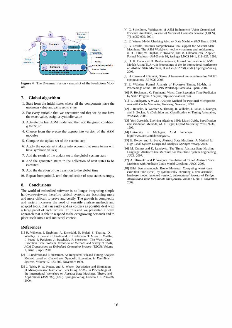
Figure 4. The Dynamic Fusion - snapshot of the Prediction Mod-ule
7. Global algorithm1. Start from the initial state: where all the components have the
unknown value andpc is set totrue
2. For every variable that we encounter and that we do not havethe exact value, assign a symbolic value
3. Activate the first ASM model and then add the guard conditiong to thepc
4. Choose from theoracle the appropriate version of the ASMmodules
5. Compute the update set of the current step
6. Apply the update set (taking into account that some terms willhave symbolic values)
7. Add the result of the update set to the global system state
8. Add the generated states to the collection of next states to beexecuted
9. Add the duration of the transition to the global time
10. Repeat from point 2. until the collection of next states is empty
8. ConclusionsThe world of embedded software is no longer integrating simplehardware/software therefore critical systems are becoming moreand more difficult to prove and certify. The growth in complexityand variety increases the need of versatile analyze methodsandadapted tools, that can easily and as costless as possible deal witha large panel of architectures. To this end we presented a novelapproach that is able to respond to the evergrowing demands and toplace itself into a real industrial context.
References[1] R. Wilhelm, J. Engblom, A. Ermedahl, N. Holsti, S. Thesing, D.
Whalley, G. Bernat, C. Ferdinand, R. Heckmann, T. Mitra, F. Mueller,I. Puaut, P. Puschner, J. Staschulat, P. Stenstrom The Worst-CaseExecution Time Problem Overview of Methods and Survey of Tools,ACM Transactions on Embedded Computing Systems (TECS), Volume7, Issue 3, April 2008.
[2] T. Lundqvist and P. Stenstrom, An Integrated Path and Timing AnalysisMethod based on Cycle-Level Symbolic Execution, inReal-TimeSystems, Volume 17, 183-207, November 1999.
[3] J. Teich, P. W. Kutter, and R. Weper, Description and Simulationof Microprocessor Instruction Sets Using ASMs, in Proceedings ofthe International Workshop on Abstract State Machines, Theory andApplications (ASM ’00), (Eds.). Springer-Verlag, London, UK, 266-286,2000.
[4] G. Schellhorn, Verification of ASM Refinements Using GeneralizedForward Simulation,Journal of Universal Computer Science (J.UCS),7(11):952-979, 2001.
[5] K. Winter, Model Checking Abstract State Machine,PhD Thesis, 2001.
[6] G. Castillo, Towards comprehensive tool support for Abstract StateMachines: The ASM Workbench tool environment and architecture,in D. Hutter, W. Stephan, P. Traverso, and M. Ullmann, eds., AppliedFormal Methods -FM-Trends 98, Springer LNCS 1641, 311–325, 1999.
[7] H. H. Daho and D. Benhamamouch, Formal Verification of ASMModels Using TLA +, in Proceedings of the 1st international conferenceon Abstract State Machines, B and Z (ABZ ’08), (Eds.). Springer-Verlag,2008.
[8] H. Casse and P. Sainrat, Otawa, A framework for experimenting WCETcomputations,ERTS06, 2006.
[9] R. Wilhelm, Formal Analysis of Processor Timing Models,inProceedings of the 11th SPIN Workshop Barcelona, Spain, 2004.
[10] R. Heckmann, C. Ferdinand, Worst-Case Execution Time Predictionby Static Program Analysis, http://www.absint.com.
[11] T. Lundqvist, A WCET Analysis Method for Pipelined Microproces-sors with Cache Memories, Goteborg, Sweeden, 2002.
[12] J. Reineke, B. Wachter, S. Thesing, R. Wilhelm, I. Polian, J. Eisinger,and B. Becker, A vDefinition and Classification of Timing Anomalies,WCET06, 2006.
[13] Yuri Gurevich, Evolving Algebras 1993: Lipari Guide, Specificationand Validation Methods, ed. E. Brger,Oxford University Press, 9–36,1995.
[14] University of Michigan, ASM homepage.http://www.eecs.umich.edu/gasm/.
[15] E. Borger and R. Stark, Abstract State Machines: A Method forHigh-Level System Design and Analysis,Springer-Verlag, 2003.
[16] M. Ouimet and K. Lundqvist, The Timed Abstract State MachineLanguage: Abstract State Machines for Real-Time System Engineering,JUCS, 2007.
[17] A. Slissenko and P. Vasilyev, Simulation of Timed Abstract StateMachines with Predicate Logic Model-Checking,JUCS, 2008.
[18] Bilel Benhamamouch, Bruno Monsuez: Computing worst caseexecution time (wcet) by symbolically executing a time-accuratehardware model (extented version),International Journal of Design,Analysis and Tools for Circuits and Systems, Volume 1, No. 1, November2009.
16

Permission to make digital or hard copies of all or part of this work for personal or classroom use is granted without fee provided that copies are not made or distributed for profit or commercial advantage and that copies bear this notice and the full citation on the first page. To copy otherwise, or republish, to post on servers or to redistribute to lists, requires prior specific permission and/or a fee. LCTES’12 June 12–13, 2012, Beijing, China. Copyright © 2012 ACM 1-59593-XXX-X/0X/000X…$5.00.
WCET Estimation of Multi-Core Processors with the MSI Cache Coherency Protocol
Pradeep Subedi and Wei Zhang Electrical and Computer Engineering Virginia Commonwealth University
Richmond, VA 23284 [email protected]
Abstract
To safely exploit multi-core processors for hard real-time systems, it is a necessity to be able to estimate the worst case execution time (WCET) of parallel programs running on a multi-core pro-cessor. For parallel programs sharing data, the cache-coherency protocol used in a multicore processor may turn an otherwise cache hit into “invalidated” or a miss, making it hard to safely estimate the WCET. In this paper, we focus on studying a multi-core processor with the cache coherency protocol MSI (Modified, Shared and Invalid). We present an approach to extend the ab-stract interpretation technique to model and statically analyze additional states caused by the MSI protocol. Our approach can safely estimate the WCET of parallel programs running on a mul-ticore processor with the MSI protocol.
Categories and Subject Descriptors
C.3 [Special-purpose and Application-based Systems]: Real-time and Embedded Systems
General Terms
Design, Performance.
Keywords WCET, Multi-core
1. Introduction
In hard real-time systems, it is crucial to compute the upper bound of the execution time of a real-time task [1], also known as worst-case execution time (WCET). One method to estimate the WCET is to exhaust all the possible program paths, for a given input through measurement, but this method may be infeasible for large programs or complex architectures with a large set of initial states. Another method is to obtain the WCET by static analysis of the program. The static analysis of the sequential programs running on a uniprocessor is done by finding the longest feasible path in the program’s control flow, and takes into consideration the tim-ing of the micro-architectural components of the system [3, 5]. For the parallel programs running on a multi-core processor with a cache-coherency protocol, in addition to considering the resource contention and inter-thread conflicts among the program threads,
it becomes crucial to calculate the worst-case delay caused by maintaining the cache coherence between different cores.
Many research efforts on WCET analysis of multi-core proces-sors [6, 7] have focused on bounding the inter-core cache interfer-ences in the shared caches. However, to the best of our knowledge, no prior work has studied the effect of cache-coherency in WCET estimation, which may be unsafe for real-time applications that have concurrent threads sharing data. By comparison, this paper examines a timing analysis method to safe-ly estimate the WCET of parallel programs running on a multi-core processor with the MSI cache coherency protocol.
2. System and Application Model
In a multi-core processor, each core usually has a private L1 in-struction cache and an L1 data cache. The L2 cache can be either shared or private. In this work, we assume a dual-core processor with a shared L2 cache as shown in Figure 1. We assume a real-time thread and another real-time or non-real-time thread are run-ning concurrently on these two cores, potentially sharing some data through both read (i.e. load) and write (i.e. store) operations. The MSI protocol [9] is used for ensuring cache coherency.
The MSI protocol has three states: Modified, Shared and Inva-lid. If a cache block is in the modified state, the cache block is valid in only one cache, and it implies exclusive ownership of the cache. A shared cache block implies that the cache block is valid, and maybe shared by multiple processors. The Invalid state of a cache block means that the copy of the data in the current cache block is outdated (because another thread from another core has modified it) and it must be updated from the shared cache or the memory. More details about the MSI can be found in [9].
Due to the existence of different cache states, the worst-case delay of memory accesses and eventually the WCET can be af-fected. For instance, even if the cache analysis indicates an access
Figure 1. A dual-core processor with shared L2 cache
17

may be always a “hit”, if the state of this cache block is “Invalid” due to a previous write by another concurrent thread, this other-wise “hit” will basically be converted into a miss by reloading the data from the lower-level memory for keeping data coherent. Therefore, we need a new method that is aware of the cache co-herency protocols to safely estimate the WCET for multicores.
3. Analysis Framework
In this section, we will present an overview of the analysis framework for a multi-core processor with the MSI cache coher-ency protocol. Figure 2 overviews our analysis framework, which involves three major steps, including the address evaluation, the cache analysis with the MSI protocol, and the WCET estimation.
3.1 Assumptions
First, we assume that the loop bounds are known through either static analysis or user annotation. Second, we assume the program has no infeasible paths. Third, we assume that the multicore pro-cessor uses the Least Recently Used (LRU) cache replacement policy and the MSI protocol for cache coherency. Forth, we as-sume there is no timing anomaly or domino effect.
To focus on cache analysis, we do not model the shared bus in this work. In our analysis, we use a shared address array �� to model all the memory blocks that are shared by different cores. We associate a tag to each shared memory block, which indicates whether a core has recently modified any data or not. More specif-ically, if the tag of a memory block m in �� is I1 (or I2), it means it is modified by core 2 (or core 1) and thus the corresponding data in core 1 (or core 2) become invalid. And if the state is s, it indi-cates the block is in the shared state.
3.2 Address Evaluation
Since we analyze both the data and the instruction caches, we need to get the set of addresses accessed by the given task. In-struction references are relatively straightforward to analyze [6]. For data references, we use the register expansion framework [2] to identify the relative addresses of all memory blocks. For each register that is used to specify the address of a load or store in-struction, we perform register expansion recursively to trace the source registers and computation is performed to evaluate the set of memory blocks accessed by that instruction. If a load instruc-tion and a store instruction are mapped to the same memory block, they can potentially cause cache coherency misses unless one can statically prove that the load occurs before the store.
Based on the assembly codes of two tasks (or threads) task 1 and task 2 running on the core 1 and core 2 respectively, two con-trol flow graphs are created and analyzed. First we analyze all the load and store instructions in tasks 1 and 2. Then the set of ad-dresses accessed by task 1 and task 2 are stored in two arrays. If any two sets of addresses are overlapped, then our algorithm iden-tifies that they point to a shared address in the main memory, which is then added into the shared address array �� .
3.3 Cache Coherency Aware Analysis of Caches
For cache analysis, the abstract interpretation method is used. Although we use the method presented in [5], we make some changes to the method to include the effect of the cache coheren-
cy. A memory block m in the shared array �� is represented as mj, where j represents the status of the block and can be I2 (i.e., modi-fied by the task running on core 1, thus invalid for the task run-ning on core 2), I1 (i.e., modified by the task running on core 2, thus invalid for the task running on core 1), or S (i.e., shared). The
function �ℎ�����, � takes a memory block m and the shared
array �� as inputs and returns the state of the memory block in the shared array. For instance, if a memory block m0 is in the shared array and its state is S, then the above mentioned function returns S, meaning the data is in the shared state in the cache.
Algorithm 1 shows how the states inside the shared array �� are changed. This algorithm is run after the evaluation of the shared variables. The initial state of all the shared memory blocks is as-sumed to be x (i.e. unknown).
Algorithm 1. Change of states inside shared array ��, with the read and write operations if (analyzing in core 1) then
for (all instructions of the task running on core 1)
if (the instruction is read) then
st = state of a memory block possibly referenced by the instruction
if (st is x or I1) then
set states of all memory blocks possibly referenced by this
instruction to S;
end if
end if
if (instruction is write) then
set states of all memory blocks possibly referenced by this
instruction to I2;
end if
end for
end if
if (analyzing in core 2) then
for (all instructions of the task running on core 2)
if (the instruction is read) then
st = state of a memory block possibly referenced by the instruction
if (st is x or I2) then
set states of all memory blocks possibly referenced by this
instruction to S;
end if
end if
if (the instruction is write) then
set states of all memory blocks possibly referenced by this
instruction to I1;
end if
end for
end if
Figure 2. Our analysis framework
18

For a task running on core 2, the state in �� is also changed as mentioned in the algorithm. For every write the task sets the state to I1 and for read operations accessing memory blocks having
state I2 (in ��), the state is changed to S and the data is fetched from the lower-level memory.
In the following, we consider an A-way set associative cache with a number of cache sets F=< f1,…,fn/A > where n = capaci-ty/line size, a cache set fi consisting of A cache lines fi = < l1,…,lA>, and all the store operations to this set represented by a set of memory blocks M= {m1,…,ms}. The function ��: � ↦ � determines the cache set where a memory block will be stored (% denotes the modulo addition): ��� � = �� ; where i= adr(m) %(n/A) +1. The function adr: M ↦N0 gives the address of each memory block [4].
The cache update function is a state update function that models the LRU replacement strategy. The following function takes a cache set and a block and returns the updated cache as follows.
����, �� =
������
["# ↦ "� ↦ ��"�$#�| & = 2 … ℎ "� ↦ ��"��| & = ℎ + 1 … +,; &� ∃". ∶ ��".� = ["# ↦ "� ↦ ��"�$#�| & = 2 … +0; 1�ℎ�2&�
3
The notation [y ↦ z] denotes a function that maps y to z.
The abstract set state �: 56↦278 maps set lines to a set of
memory blocks. An abstract cache state 9: � ↦:; maps sets to
abstract set states. :; denotes the set of all abstract set states and <; denotes the set of all abstract cache states. The abstract update function is modeled as
�=>;�9, � = 9[��� � ↦ �= � ?�9���� ��, @, The join functions that we use for must, may, and persistence
analysis are based on [4].The join function for must analysis is similar to set intersection, except that if a memory blocks has two different ages in two abstract cache states, the join function takes the oldest age. A;B;��#, �C� = �
where, ��"D� = E |∃"� , "F2&�ℎ ∈ �1�"��, ∈ �2�"F� �H D = max�a, b�0
∩ E | ∈ �#�"N��H ∄"P2&�ℎ ∈ �C�"P�03 ∩ E | ∈ �#�"N��H ∄"P2&�ℎ ∈ �C�"P�03 The join function for may analysis and persistence analysis
are similar to the above except that in may analysis, set union is performed and the minimum age is taken, and in persistence anal-ysis set union is used and the maximum age is taken. The abstract interpretation method [5] is used at both L1 and L2.
For the level 1 instruction and data caches, must, may and per-sistence analyses are firstly conducted. In case of an instruction cache, the analysis is done as specified in [5]. The L2 cache anal-ysis is similar to the L1 cache analysis except that it does not take into consideration the blocks that are classified as AH (i.e. Always Hits [5]) in L1 caches.
The references are provided with Always (A), Never (N), and Uncertain (U) tags for the L2 cache analysis.
L1 Classification L2 tag
AH AM
NC
N A U
Table 1. L2 tag for different L1 classification of memory blocks
If a reference tag is N, the abstract cache state is not updated
because they do not access the L2 cache at all. For the reference with tag U, two abstract cache states are created; one updates the reference while another does not update the reference and both of them are then joined later.
Since the L2 cache is a unified cache, for each instruction, ini-tially the abstract cache state is updated by using the update func-tion of the instruction cache analysis first. If the instruction is a load/store instruction, and it references a set of memory blocks M, then the result of the update function for instruction cache is up-dated by the update function of the data cache analysis.
Now we have to take into consideration the cache conflicts in L2 because it is shared and a task T2 executing on core 2 can potentially conflict with task T1 executing on core 1. This brings changes in the hit/miss classification of the memory blocks in T1. Since the references with N tag never access L2 cache, we need not consider these references for the conflict analysis. Now if the memory block in T1 is classified as AM or NC, then the cache state remains the same because the interfering task cannot down-grade it further. So only the memory blocks with AH are affected. Since the memory blocks can be evicted from the cache, we clas-sify these interfering memory blocks as Non-classified (NC). For set-associative caches, the method introduced in [7] can be used for conflict analysis, where the age of the memory block is taken into consideration and if the number of conflicting memory blocks from the conflicting tasks is less than or equal to the N-age of memory block in T1, where N is the associativity of the cache. The cache state of the memory block is not modified because it will not be evicted from the cache, resulting in the AH for the L2 cache. The age of a memory block is equal to the line number of the cache block that the memory block is mapped into.
3.4 WCET estimation
Table 2 shows the worst-case access latency for a reference that is taken into consideration during the WCET estimation for a basic block, where hitL1 is the latency of a hit at the level 1 cache; hitL2
is the latency due to a miss in the L1 cache but a hit in the level 2 cache; and missL2 is the latency due to misses in both the level 1 and the level 2 caches (i.e., the data must be fetched from the main memory). After finding out the worst case latencies for all the memory references, our algorithm then sums up these worst case latencies to derive the WCET of caches without considering the cache coherency misses.
L1 cache L2 cache Worst-case Access
Latency
AH - hitL1
AM AH hitL2 AM AM missL2 AM NC missL2 NC AH hitL2 NC AM missL2 NC NC missL2
Table 2. Access Latency of a reference in the worst case given its classification
19

To safely estimate WCET for real-time tasks that share data across different cores, we must incorporate the delay caused by cache coherency misses. Algorithm 2 described below presents our method of finding the worst-case delay caused by all the in-validations inside a basic block, which provides an important basis to derive the WCET for a multicore processor with the MSI protocol.
Algorithm 2. Latency caused by invalidation of memory block m inside a basic block b; shared (��, ) returns the state of memory block in shared array; I1 means invalid for core 1; and I2 means invalid for core 2.
costinvalidation =0;
invalidation=0;
inst= first instruction of the basic block;
repeat
if (inst is a read instruction) then
n = number of memory blocks possibly accessed by inst;
if (n==1) then
if(shared (��, )==I1) then
if (analyzing core 1 and reference classification is
not (AM for L2 or NC for both L1 and L2) ) then
invalidation=invalidation+1;
end if
else
if (shared (��, )==I2) then
if (analyzing core 2 and reference classi-
fication is not (AM for L2 or NC for
both L1 and L2)) then
invalidation=invalidation+1;
end if
end if
end if
else
if (n>1) then
mk = any one memory block possibly referenced;
for(all possible mk)
if(shared (��, Q)==I1) then
if (analyzing core 1 and reference classification is
not (AM for L2 or NC for both L1 and L2)) then
invalidation= invalidation+1;
end if
else
if (shared (��, Q)==I2) then
if (analyzing core 2 and reference classifica-
tion is not (AM for L2 or NC for both L1 and
L2)) then
invalidation= invalidation+1;
end if
end if
end if
end if
end if
end if
until (all instructions in basic block b finish)
costinvalidation = invalidation*missL2 latency;
return costinvalidation
Suppose latb is the worst case latency for a basic block b without considering invalidation and bi is the number of execution times of basic block i, then total cost for that basic block can be computed as the follows, where costinvalidation can be calculated by using the Algorithm 2.
∑ (latb+costinvalidation)×bi
Now the longest path search [8] or the implicit path enumeration technique (IPET) [10] can then be applied to obtain the WCET of the whole thread. 4. Concluding Remarks and Future Work In this paper, we have presented the challenge of timing analysis for multicore processors with cache coherency protocols. To ad-dress this problem, we extend the abstract interpretation technique to model additional cache states, which can safely derive the worst-case cache performance by considering coherent cache misses. Our ongoing work includes implementation and validation of the proposed static analysis, and the exploration of additional techniques to improve the tightness of analysis, for example, us-ing timing overlapping information among concurrent threads to reduce overestimation.
References
[1] R. Wilhelm et al., The worst-case execution-time problem- overview of methods and survey of tools. Trans. Emb. Comp. Syst., vol. 7, no. 3, 2008.
[2] G. Balakrishnan and T.W. Reps., Analyzing memory accesses in x86 executables. CC, 2004.
[3] S. Chattopadhyay, A. Roychoudhury., Unified Cache Model-ing for WCET Analysis and Layout Optimizations. Proceed-ings of the 2009 30th IEEE Real-Time Systems Symposium, p.47-56, December 01-04, 2009.
[4] M. Alt, C. Ferdinand, F. Martin, and R. Wilhelm., Cache behaviour prediction by abstract interpretation. SAS. Springer-Verlag, 1996.
[5] H. Theiling, C. Ferdinand, and R. Wilhelm. Fast and precise WCET prediction by separated cache and path analyses. Re-al-Time- Systems, 18(2/3), 2000.
[6] S. Chattopadhyay, A. Roychoudhury and T. Mitra., Modeling Shared Cache and Bus in Multi-cores for Timing Analysis. 13th International Workshop on Software and Compilers for Embedded Systems (SCOPES), 2010.
[7] Y. Li, Vivy S., Yun Liang, T. Mitra and A.Roychoudhury., Timing Analysis of Concurrent Programs Running on Shared Cache Multi-cores. IEEE Real-time System Symposium (RTSS), 2009.
[8] V. Suhendra, T. Mitra, A. Roychaudhary, and T. Chen. Effi-cient detection and exploitation of infeasible paths for soft-ware timing analysis. Proceedings of the Design Automation Conference, 2006.
[9] Yan Solihin, Fundamentals of Parallel Computer Architec-ture, Solihin Publishing and Consulting LLC, 2009.
[10] Y. S. Li and S. Malik. Performance analysis of embedded software using implicit path enumeration. In Proc. of the ACM SIGPLAN Workshop on Languages, Compilers, and Tools for Real-Time Systems, 1995.
Acknowledgement
This work is partially supported by NSF grant CCF 0914543.
20

Introducing Service-oriented Concepts into Reconfigurable MPSoC on FPGA for Coarse-grained
Parallelization Chao Wang1,2+ Xi Li1 Peng Chen2 Junneng Zhang2 and Xuehai Zhou1
1University of Science and Technology of China, Hefei, Anhui China, 230027 2Suzhou Institute of Advance Study, USTC, Suzhou, Jiangsu, China, 215123
{saintwc,zjneng, qwe123}@mail.ustc.edu.cn {llxx,xhzhou}@ustc.edu.cn
ABSTRACT
High level programming into hardware is posing significant challenge for reconfigurable modular embedded systems. In this paper we propose SOREP: a Service-oriented Reconfigurable Prototype, which introduces service-oriented architecture (SOA) concepts to reconfigurable multiprocessor system on chip (MPSoC) on field programming gate arrays (FPGA) for coarse-grained parallelization. SOA concepts can provide a uniform programming model as well as computing resources integration manners to MPSoC hardware. With the benefits of SOA and state-of-the-art reconfigurable technologies, novel MPSoC design paradigms are encountering new opportunities for traditional technical challenges, including reconfigurable task execution, programming models and out-of-order scheduling. For demonstration, a service-oriented reconfigurable MPSoC prototype has been built on FPGA, regarding embedded processors and IP cores as computing servants. The preliminary results demonstrate the prototype can achieve more than 95% of the theoretical peak speedup on average.
Categories and Subject Descriptors
D.4.1 [Process Management]: Multiprocessing/ multiprogramming / multitasking
General Terms Algorithms, Design
Keywords Service-oriented architecture, multiprocessor system-on-chip, reconfigurable computing,
1. Introduction and Motivation FPGA based reconfigurable MPSoC has been considered as one of the promising future microprocessor design paradigms [1]. However, current MPSoC developers are still suffering from limited programming ability and high complexity during the design of different architectures for various applications [2]. Whenever hardware is reconfigured, developers need to redesign the middleware, programming models or even the tool chains. Moreover, runtime task partition and scheduling schemes need also to be carefully reconsidered, which in case could dramatically drag down the degree of task parallelization. In order to address the
above challenges, our research tentatively introduces service-oriented concepts into reconfigurable MPSoC.
SOA concepts have been successfully applied in software engineering and web services, and it’s shifting towards lower level, such as operating systems [3]. However, to our best knowledge, so far, few existing literature have been conducted to introduce SOA to reconfigurable hardware architecture designs. Instead, most state-of-the-art FPGA based research platforms are constructed in specific hardware, which means users need to acquire the specific hardware configurations and scheduling schemes of the system to handle the tasks distribution manually. Otherwise, the parallelization degree could be dramatically dragged down due to unsophisticated programmer’s experiences. Therefore, the automatic parallelization degrees are still worth pursuing.
From the weakness exploration of current studies, the motivation of this paper is to integrate SOA with MPSoC to absorb the advantages of both concepts. From the exploration of SOA concepts’ benefits, we can conclude that there are at least two significant advantages through integrating SOA to MPSoC platform. Firstly, servant integration interfaces are well defined, which facilitate researchers to add/remove modularized function units expeditiously during prototype system construction. Secondly, with unified API, users are no longer concerned about the target hardware, which means the partition and mapping is handled by SOREP automatically. This feature will significantly ease the burden of programmers, shorten MPSoC design cycle, and reduce the complexity to construct a heterogeneous single chip cloud.
In this paper, we tentatively propose a prototype to demonstrate SOA concepts into heterogeneous reconfigurable multi-core platform design. Based on the previous research of [4], this paper builds a hardware prototype on FPGA with state-of-the-art dynamic partial reconfigurable technologies. We claim following contributions:
1) This paper brings SOA concepts into real reconfigurable MPSoC hardware, and builds a service-oriented reconfigurable prototype SOREP. SOREP is implemented on state-of-the-art Xilinx FPGA with multiple Microblaze processors and adaptable IP cores. The reconfigurable characteristics demonstrate the high flexibility and scalability of SOREP.
21

2) SOREP provides an efficient experimental research platform to attack traditional key challenges including IP reconfiguration, task partition, and out-of-order task scheduling. First, a self reconfigurable task execution model based on state-of-the-art Xilinx Early Access Partial Reconfiguration (EAPR) is carried out to minimize the reconfiguration overheads. Second, when the reconfiguration is ready, tasks are adaptively remapped to computing servants without rewriting or recompilation. Third, we also apply renaming techniques from instruction level to chip level which can automatically detect inter-task data hazards, and then distribute tasks to computing servants for out-of-order execution.
The novelty of SOREP against current state-of-the-art MPSoC architectures are listed as follows:
1) SOA concepts bring unified programming models and servant integration interfaces, which can largely facilitate researchers to construct flexible experimental platforms. Therefore developers can concentrate on the key issues of scheduling, on chip interconnection methodologies, and reconfigurable technologies, etc. SOREP can ease the burden of MPSoC architects and shorten the time to market (TTM) of chips.
2) SOREP maintains middleware to fully support automatic parallelization, including adaptive task partition and out-of-order scheduling. In our approach, the middleware is designed under the IP dynamic reconfigurable condition. We integrate those methods into a SOREP framework, which can be easily customized to build an application-specific MPSoC.
2. SOREP Architecture and Concepts Before SORA architecture is introduced, we define the following terms at first.
Service: A service is defined as a specific kind of functions with programming interfaces. All services are packaged into libraries and can be invoked by function calls.
Servants: Servants refer to functional modules dedicated to provide services to run specific tasks in hardware. All servants are IP cores packaged in same manners.
Figure 1 [a] illustrates the similarity of traditional SOA concepts. All services are provided via front-end uniform interfaces with service definitions. In the back stage, each service is composed of specific functionalities transferred from software libraries and data bases through the uniform service interfaces. Similarly, the situation on MPSoC is presented in Figure 1 [b], where the service definition interfaces are turned into the application programming interfaces (APIs), and each service providers are turned into either a microprocessor, or a DSP/hardware IP core.
SOREP architecture consists of servants classified in two categories: one Scheduling Servants is employed for task partitioning, mapping and run-time scheduling. As the kernel component, scheduling servant also plays a key role in exploration for inter-task data dependencies. It can be regarded as non-scalable as we move from one to ten to hundreds of cores. However, it is possible to instantiate additional scheduling servants if the architecture scale is increased to more than 8 cores. Computing Servants are designed to provide computing services and can be further classified into hardware and software servants. Software servants run on microprocessors with libraries, while hardware servants are implemented in IP cores to run only one specific kind of tasks.
The scheduling servant is connected to computing servants and peripheral modules through via FSL channels. All the hardware servants are loaded from IP libraries dynamically. The middleware is composed of three levels: application, middleware layer and communication layer.
2.1 Application layer Application layer consists of service API, run-time libraries, and application profiling. In order to maintain the consistent user programming behaviors, system should provide unified high-level abstract interfaces. The entire API is utilized for spawning computational tasks and receiving results from scheduling servant to computing servants. Moreover, in order to fully benefit from the advantages of the self-reconfiguration techniques, APIs are be kept unchanged after hardware reconfiguration. In order to prevent the considerable overheads of maintaining memory consistency,
[a] Typical Service-Oriented Architecture [b] Mapping Services to MPSoC
Figure 1. Typical Service-Oriented Architecture and Services model on MPSoC
22

we utilize message passing mechanisms like MPI). Two types of primitives are provided: blocking interfaces will stall the execution and wait until results return, while non-blocking interfaces will continue, results will return through interrupts.
2.2 Middleware layer In this Section, we give an overview of the services middleware layer, which includes task partitioning, scheduling and reconfigurable task execution models.
(1) Automatic task partitioning The automatic task partition methods supervise the
procedure of how a single task is divided and then mapped to IP core. As each IP core can run only one kind of task, a task-to-servant table is employed to identify the target servant for each task. The table maintains a mapping of tasks to servants to virtualize the selection of the destination core. Each table entry contains the task ID currently running on that core as well as a count of the number of issued tasks destined for that core.
(2) Out-of-order task scheduling Scheduling servant is in charge of when the task can be
issued. For tasks which are independent from each other, they can be issued simultaneously. However, in many cases, inter-task data hazards (such as RAW hazards) make the tasks run in sequence.
In order to fully exploit the potential task level parallelism, we demonstrate traditional Scoreboarding and Tomasulo algorithms from instruction level to chip level for out-of-order task execution. Both techniques are common knowledge in textbooks used to detect data hazards automatically, while Tomasulo also can further eliminate WAW hazards by renaming technologies. Since the two technologies are quite familiar to architectural researchers, we will directly show some experimental results in Section 4.
(3) Reconfigurable task execution model At start-up, certain IP cores are loaded as servants in
prior to task execution to provide an initialized run-time environment. When the target servant is ready, it can receive service requests from scheduling servant, run the task, and then return the result by raising an interrupt. However, if the target is not loaded during execution, current hardware should be reconfigured dynamically. Furthermore, if there are no more free areas in the chip, some of the present IP cores should be switched out. FIFO or LRU policies can be utilized under different conditions. For demonstration, self reconfiguration technologies based on Xilinx EAPR are introduced to support servant replacement.
3. SOREP Prototype on FPGA We implemented a prototype for SOREP on a state-of-art Xilinx Virtex-5 XC5VLX110T FPGA. One Microblaze processor is used for scheduling servant, and another Microblaze processor is employed as software computing servant. Also, four hardware computing servants were integrated, including Data Accumulation (adder), and three EEMBC DENBench test cases of IDCT, AES_ENC and AES_DEC. For each service, one software computing servant is designed in C library running on Microblaze, and one hardware computing servant is described in HDL and packaged as IP core.
Figure 2 presents the self reconfigurable prototype in single FPGA. We integrate four hardware servants which can be substituted to other servants in the IP library. The reconfiguration procedure is manipulated by an internal controller without user interaction. Based on the hardware prototype, Figure 2 also gives a sample test case with the running time for each type of single task. The running time for each type of task is given in Figure 2. When the specific API is invoked during execution, an automatic adaptive
Figure 2. SOREP prototype built in single FPGA and sample applications
23

mapping scheme will decide the target computing servant for each task. In this paper, due to the page limitations, we only give a demonstrative experiment to compare to mechanisms in parts of the total design.
All applications are running on the scheduling servant at first and then scheduled to certain computing servant. For demonstration, we use a greedy strategy: when there is available hardware computing servants, the task will be sent to hardware. Unfortunately, if all the hardware servants are occupied, the task will be dispatched to software computing servants. If all the software is also occupied, then SOREP can only wait for other applications to complete and first tries to schedule the application in hardware. This method is considered to show the effectiveness of partition scheme, and can be replaced by other algorithms to get a better result.
Within the hardware and programming interfaces, we measured the performance and accuracy of the FPGA platform, with the Scoreboarding and Tomasulo scheduling algorithms respectively.
Figure 3. Comparison between Scoreboarding and Tomasulo
The empirical result of the test case in Figure 2 is presented in Figure 3. The length of sequences N indicates the first N tasks listed in Figure 2. The empirical results are quite close to the theoretical speedup, with most of the results more than 95% accuracy. In our scope, this result shows that Scoreboarding and Tomasulo algorithms can run tasks out-of-order with lower overheads than Task superscalar [5]. Compared to Scoreboarding, Tomasulo has higher scheduling overheads, which leads to a bigger gap between experimental and theoretical value. However, since Tomasulo can not only detect WAW and WAR hazards but also eliminate them by register renaming, the overall speedup is significantly larger than Scoreboarding.
We have also demonstrated the self-reconfigurable MPSoC prototype with Xilinx EAPR methods, and more than one IP cores can be reconfigured at run-time, with the FPGA chip-programming time at 409 ms approximately (For AES and DES IP modules).
In the prototype, we have integrated two Microblaze processors and four servants, as well as peripheral blocks. The system has been synthesized and Table I outlines the hardware cost for the entire system in single FPGA. SORA system takes 26% area in LUTs and 7% in registers overall, which means we can integrate more than 20 servants at the same time. Considering the abundant hardware resources
supplied in FPGA, the resources are acceptable to construct a heterogeneous CMP.
TABLE I. SYSTEM HARDWARE COSTS OF THE ARCHITECTURE
Resource Status PercentNumber of Slice Registers 6493 out of 17280 7.00%
Number of Slice LUTS 18209 out of 69120 26% Number used as logic 17577 out of 69120 25%
Number used as Memory 601 out of 17920 3% Number of External IOBs 4 out of 640 1%
Number of BUFGs 3 out of 32 9%
4. Conclusion and Future work
In this paper, we introduced SOA concepts to MPSoC platform for chip level parallelization. SOA concepts bring new opportunities to traditional MPSoC challenges including unified programming interfaces, automatic task partitioning, and out-of-order scheduling scalable hardware reconfigurations. Empirical results on FPGA shows that SOA can efficiently facilitate researchers to construct application specific MPSoC with adoptable modules with high flexibility. Both the software scheduling overheads and hardware utilization are acceptable.
This work is still working-in-progress and there are numerous future directions worth pursuing. First, task partition and adaptive mapping methodologies will be essential to efficiently support automatic parallelization. Second, although significant researches are underway for programming, little work has been done on integrating reconfigurable FPGAs with conventional programming paradigms. Finally, the chip-level parallelization also proposes new challenges on out-of-order task scheduling, to break the area and resources limitations of FPGA devices.
References [1]. Shekhar, B. and Andrew A.C. 2011. The future of
microprocessors. Communications of ACM, 54, 5(May. 2011), ACM, New York, NY, 67-77. DOI= http://doi.acm.org/10.1145/1941487.1941507
[2]. Satnam, S. 2011. Computing without processors. Communications of ACM, 54, 8 (Aug. 2011), ACM, New York, NY, 46-54. DOI=http://doi.acm.org/10.1145/ 1978542.1978558
[3]. David W., Anant A., Factored operating systems (fos): the case for a scalable operating system for multicores. 2009, ACM SIGOPS Operating Systems Review, 43, 2 (Apr.2009), ACM, New York, NY, 76-85. DOI=http://dx.doi.org/10.1145/1531793.1531805
[4]. Wang, C., Zhang J., et al. (2011). SOMP: Service-Oriented Multi Processors. Proceedings of the 2011 IEEE International Conference on Services Computing, IEEE Computer Society: 709-716. DOI=http://dx.doi.org/10.1109/SCC.2011.26
[5]. Etsion Y., Cabarcas F., Rico A., Ramirez A., et al., Task Superscalar: An Out-of-Order Task Pipeline, in Proceedings of the 2010 43rd Annual IEEE/ACM International Symposium on Microarchitecture. 2010, IEEE Computer Society. p. 89-100. DOI=http://dx.doi.org/10.1109/MICRO.2010.13
24