process automation made personal - brucontrol.com · o flexible & simple scripting language for...
TRANSCRIPT
BRUCONTROL Process Automation Made Personal
BruControl Version 1.1 & Firmware v45
Updated 5/7/2019
BruControl v1.1 2
BruControl Copyright 2019. Proprietary and Confidential.
Table of Contents
Features and Highlights .................................................................................................................. 6
Overview ......................................................................................................................................... 8
System Requirements ................................................................................................................... 10
Quick Start ..................................................................................................................................... 12
BruControl Hardware .................................................................................................................... 13
Interface Considerations ............................................................................................................... 13
Device Types ................................................................................................................................. 14
Interface Wiring Maps .................................................................................................................. 15
Control System Considerations ..................................................................................................... 15
Interface Setup .............................................................................................................................. 16
Application Setup .......................................................................................................................... 17
Application Files ............................................................................................................................ 17
BruControl Application ................................................................................................................. 19
Application Environment .............................................................................................................. 19
Application Settings ...................................................................................................................... 19
Interfaces .................................................................................................................................. 20
Configuration ............................................................................................................................ 22
Security ..................................................................................................................................... 23
License ....................................................................................................................................... 24
Environment ............................................................................................................................. 25
Data Exchange ........................................................................................................................... 26
Email .......................................................................................................................................... 27
About ......................................................................................................................................... 29
Touch Keypad ................................................................................................................................ 29
Interface Communication ............................................................................................................. 30
Workspaces ................................................................................................................................... 31
Elements ....................................................................................................................................... 32
Environment Security.................................................................................................................... 33
User Control .................................................................................................................................. 33
BruControl v1.1 3
BruControl Copyright 2019. Proprietary and Confidential.
Device Elements ............................................................................................................................ 33
Digital Input ............................................................................................................................... 34
Counter Input ............................................................................................................................ 35
Analog Input .............................................................................................................................. 37
SPI Sensor Input ........................................................................................................................ 38
1-wire Temperature Input ........................................................................................................ 39
Hydrometer Input ..................................................................................................................... 40
Digital Output ............................................................................................................................ 41
PWM Output (Analog Output) .................................................................................................. 43
Duty Cycle Output ..................................................................................................................... 45
Hysteresis Output ..................................................................................................................... 46
PID Output ................................................................................................................................ 48
Deadband Output ..................................................................................................................... 50
Device Element Calibrations ......................................................................................................... 53
Linear Offset .............................................................................................................................. 55
Linear Multiplier/Divider .......................................................................................................... 55
Floor .......................................................................................................................................... 56
Ceiling ........................................................................................................................................ 56
Resistance Temperature (RTD) ................................................................................................. 57
Thermistor (Steinhart-Hart) ...................................................................................................... 57
Celsius to Fahrenheit ................................................................................................................ 58
Fahrenheit to Celsius ................................................................................................................ 58
Kelvin to Fahrenheit .................................................................................................................. 58
Fahrenheit to Kelvin .................................................................................................................. 58
Lookup Table ............................................................................................................................. 58
Text Format ............................................................................................................................... 59
Practical Applications ................................................................................................................ 60
Timer Elements ............................................................................................................................. 60
Alarm Elements ............................................................................................................................. 62
Graph Elements............................................................................................................................. 63

BruControl v1.1 4
BruControl Copyright 2019. Proprietary and Confidential.
Global Elements ............................................................................................................................ 65
Inspector Elements ....................................................................................................................... 66
Button and Switch Elements ......................................................................................................... 67
Element Appearance ..................................................................................................................... 69
Data Exchange Protocol ................................................................................................................ 74
Single Global ............................................................................................................................. 74
Multiple Globals ........................................................................................................................ 75
Scripts ............................................................................................................................................ 75
BruControl Script Language .......................................................................................................... 78
Introduction .................................................................................................................................. 78
Name Convention and Syntax ....................................................................................................... 78
Sections ......................................................................................................................................... 78
Execution Delays ........................................................................................................................... 79
Comments & Formatting .............................................................................................................. 79
Variables ........................................................................................................................................ 80
Element Properties ....................................................................................................................... 82
Variable Precision ......................................................................................................................... 85
Sync ............................................................................................................................................... 86
Wait ............................................................................................................................................... 86
If-Else ............................................................................................................................................. 87
Subroutines ................................................................................................................................... 88
Timers ........................................................................................................................................... 89
Alarms ........................................................................................................................................... 89
Buttons and Switches .................................................................................................................... 90
Workspace Display ........................................................................................................................ 90
Script Execution ............................................................................................................................ 91
Print ............................................................................................................................................... 91
Display ........................................................................................................................................... 92
Appendix ....................................................................................................................................... 94
Interface Preparation .................................................................................................................... 94
BruControl v1.1 5
BruControl Copyright 2019. Proprietary and Confidential.
Interface Overview ........................................................................................................................ 95
Interface Firmware Versions ......................................................................................................... 96
Interface Recommendations ........................................................................................................ 96
Interface Firmware Installation and Setup ................................................................................... 97
Interface Control Codes ................................................................................................................ 99
Device Elements Enabled / Affected via Scripts ......................................................................... 100
WINC1500 Wi-Fi Considerations ................................................................................................. 101
SPI Sensor Considerations ........................................................................................................... 102
BruControl as a Server ................................................................................................................ 102
Power Failures ............................................................................................................................. 102
Power-On Device Configurations ................................................................................................ 103
Linear Calibration Principles ....................................................................................................... 103
Analog Input Considerations ....................................................................................................... 105
Upgrade From v1.0 ..................................................................................................................... 106
Version History ............................................................................................................................ 107
Technical Assistance ................................................................................................................... 109
BruControl v1.1 6
BruControl Copyright 2019. Proprietary and Confidential.
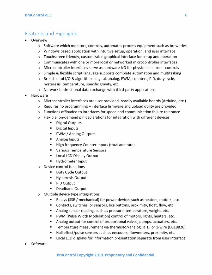
Features and Highlights • Overview
o Software which monitors, controls, automates process equipment such as breweries o Windows based application with intuitive setup, operation, and user interface o Touchscreen friendly, customizable graphical interface for setup and operation o Communicates with one or more local or networked microcontroller interfaces o Microcontroller interfaces serve as hardware I/O for physical electronic controls o Simple & flexible script language supports complete automation and multitasking o Broad set of I/O & algorithms: digital, analog, PWM, counters, PID, duty cycle,
hysteresis, temperature, specific gravity, etc. o Network bi-drectional data exchange with third-party applications
• Hardware o Microcontroller interfaces are user provided, readily available boards (Arduino, etc.) o Requires no programming – interface firmware and upload utility are provided o Functions offloaded to interfaces for speed and communication failure tolerance o Flexible, on-demand pin declarations for integration with different devices
Digital Outputs Digital Inputs PWM / Analog Outputs Analog Inputs High frequency Counter Inputs (total and rate) Various Temperature Sensors Local LCD Display Output Hydrometer Input
o Device control functions Duty Cycle Output Hysteresis Output PID Output Deadband Output
o Multiple device type integrations Relays (SSR / mechanical) for power devices such as heaters, motors, etc. Contacts, switches, or sensors, like buttons, proximity, float, flow, etc. Analog sensor reading, such as pressure, temperature, weight, etc. PWM (Pulse Width Modulation) control of motors, lights, heaters, etc. Analog output for control of proportional valves, pumps, actuators, etc. Temperature measurement via thermistor/analog, RTD, or 1-wire (DS18B20) Hall effect/pulse sensors such as encoders, flowmeters, proximity, etc. Local LCD displays for information presentation separate from user interface
• Software

BruControl v1.1 7
BruControl Copyright 2019. Proprietary and Confidential.
o Windows application serving as one unified setup and control environment o Modern intuitive touch-panel interface with selectable themes o Small CPU/memory footprint runs on most PC hardware o Multi-page "Workspaces" for display and control of different machines & systems o Customizable graphical representation and control of physical devices o Real-time display, control, and configuration of devices, timers, alarms, buttons o Continuous device data collection, providing immediate access to historical data o Flexible graphing of selectable values for historical data presentation/analysis o Multiple, fully customizable layouts with user selectable images and formatting o Supports multiple control types per physical device (e.g. Duty Cycle and PID) o Communicates with multiple local or remote interfaces for unlimited I/O o Local interfaces connect via USB & remote interfaces via standard TCP network o Requires no programming for setup or user interface configuration o Flexible & simple scripting language for process automation / autonomy o Scripting includes flow control, variable handling, device control, and properties o Concurrent Scripts to manage different machine systems and perform multi-tasking o Parameters and calibrations independently configurable for each device o Layered calibrations including Thermistor, RTD, Offset, Multiplier, Lookup, etc. o Data Exchange permits communication with external networked systems o Security system to limit unauthorized changes to environment or device states o Multiple configurable alarms with hardware activations and email notifications o Multiple count-up or count-down timers with direct-acting alarm capabilities o Multiple variables for handling and monitoring data or operation performance o Multiple buttons or switches for user interaction with automated processes
BruControl v1.1 8
BruControl Copyright 2019. Proprietary and Confidential.
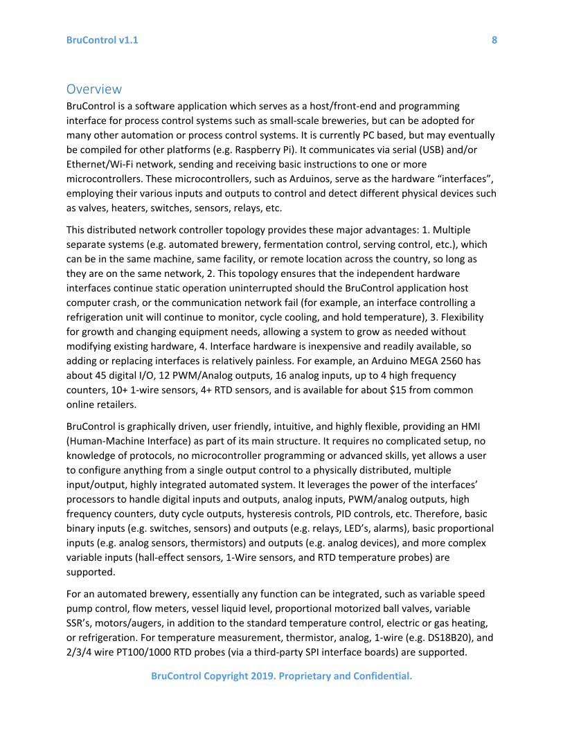
Overview BruControl is a software application which serves as a host/front-end and programming interface for process control systems such as small-scale breweries, but can be adopted for many other automation or process control systems. It is currently PC based, but may eventually be compiled for other platforms (e.g. Raspberry Pi). It communicates via serial (USB) and/or Ethernet/Wi-Fi network, sending and receiving basic instructions to one or more microcontrollers. These microcontrollers, such as Arduinos, serve as the hardware “interfaces”, employing their various inputs and outputs to control and detect different physical devices such as valves, heaters, switches, sensors, relays, etc.
This distributed network controller topology provides these major advantages: 1. Multiple separate systems (e.g. automated brewery, fermentation control, serving control, etc.), which can be in the same machine, same facility, or remote location across the country, so long as they are on the same network, 2. This topology ensures that the independent hardware interfaces continue static operation uninterrupted should the BruControl application host computer crash, or the communication network fail (for example, an interface controlling a refrigeration unit will continue to monitor, cycle cooling, and hold temperature), 3. Flexibility for growth and changing equipment needs, allowing a system to grow as needed without modifying existing hardware, 4. Interface hardware is inexpensive and readily available, so adding or replacing interfaces is relatively painless. For example, an Arduino MEGA 2560 has about 45 digital I/O, 12 PWM/Analog outputs, 16 analog inputs, up to 4 high frequency counters, 10+ 1-wire sensors, 4+ RTD sensors, and is available for about $15 from common online retailers.
BruControl is graphically driven, user friendly, intuitive, and highly flexible, providing an HMI (Human-Machine Interface) as part of its main structure. It requires no complicated setup, no knowledge of protocols, no microcontroller programming or advanced skills, yet allows a user to configure anything from a single output control to a physically distributed, multiple input/output, highly integrated automated system. It leverages the power of the interfaces’ processors to handle digital inputs and outputs, analog inputs, PWM/analog outputs, high frequency counters, duty cycle outputs, hysteresis controls, PID controls, etc. Therefore, basic binary inputs (e.g. switches, sensors) and outputs (e.g. relays, LED’s, alarms), basic proportional inputs (e.g. analog sensors, thermistors) and outputs (e.g. analog devices), and more complex variable inputs (hall-effect sensors, 1-Wire sensors, and RTD temperature probes) are supported.
For an automated brewery, essentially any function can be integrated, such as variable speed pump control, flow meters, vessel liquid level, proportional motorized ball valves, variable SSR’s, motors/augers, in addition to the standard temperature control, electric or gas heating, or refrigeration. For temperature measurement, thermistor, analog, 1-wire (e.g. DS18B20), and 2/3/4 wire PT100/1000 RTD probes (via a third-party SPI interface boards) are supported.

BruControl v1.1 9
BruControl Copyright 2019. Proprietary and Confidential.
Interfaces need to be connected to ancillary hardware as appropriate, for example, mechanical and solid state relays would be used to power high voltage devices. In addition, while BruControl provides the main HMI, a local LCD displays may be connected to interface hardware to report values locally (for example, a fermentation controller displaying temperature at the location of the fermenter).
BruControl is easily configured, so a completely automated brewery or machine controller can be built in stages without having to start from scratch with each iteration. Additional interfaces can be added as a user’s system grows. BruControl gives the user the ability to separate different machines or machine subsystems into different processes, so a distributed control system can be built as the user sees fit.
One of BruControl’s biggest advantages is its incorporation of a unique, yet simple scripting language that allows the user to program automatic management of the physical inputs, outputs, and other data. As many Scripts can run concurrently as desired. This functionally creates a multi-tasked process control environment. This scripting language is well documented and easy to adopt, even for non-programmers. Basic functions like sections, time delays, if/then/else, waits, variable manipulation/mathematics, element properties, timer and alarm management, and script execution are included. Scripts can be run, paused, stepped-through, or started in different places.
To build a control system run by BruControl, the user first plans, sources, and builds the physical control system hardware (e.g. control panel), selecting an interface (microcontroller) and its associated ancillary hardware and devices. Each pin on the interface will be connected to appropriate hardware for that device’s function. For example, a digital output on the interface could be connected to an SSR which will electronically switch power to a heating element. Schematics for such systems are often found online, or through BruControl’s support. The user then uploads the BruControl provided firmware into the interface. The user need not have any programming tools, and the firmware code is not user-editable. There will be different versions of the firmware depending on the interface hardware used. The interfaces can be connected via their native serial (USB) connection or the via Network. If via network, Ethernet or Wi-Fi hardware must be incorporated natively or via a shield (plug-in board) or module into the interface. The user then runs the BruControl application, first linking it to the interface(s), then creating virtual devices tied to that interfaces’ pins (ports).
The biggest challenge for a user setting up a BruControl system (like any controller system) will be hardware integration. Stated simply, knowledge and experience with electrical integration, low and high voltage wiring, electrical noise management, schematic writing and reading, electrical safety, and building control systems is needed. Integration hardware will include mechanical or solid state relays and boards, power supplies, high voltage contactors, sensors, switches, lighted indicators, daughter boards, and all associated wiring and terminations. Certain inputs or outputs may need additional custom circuitry such as resistors, capacitors, etc.
BruControl v1.1 10
BruControl Copyright 2019. Proprietary and Confidential.
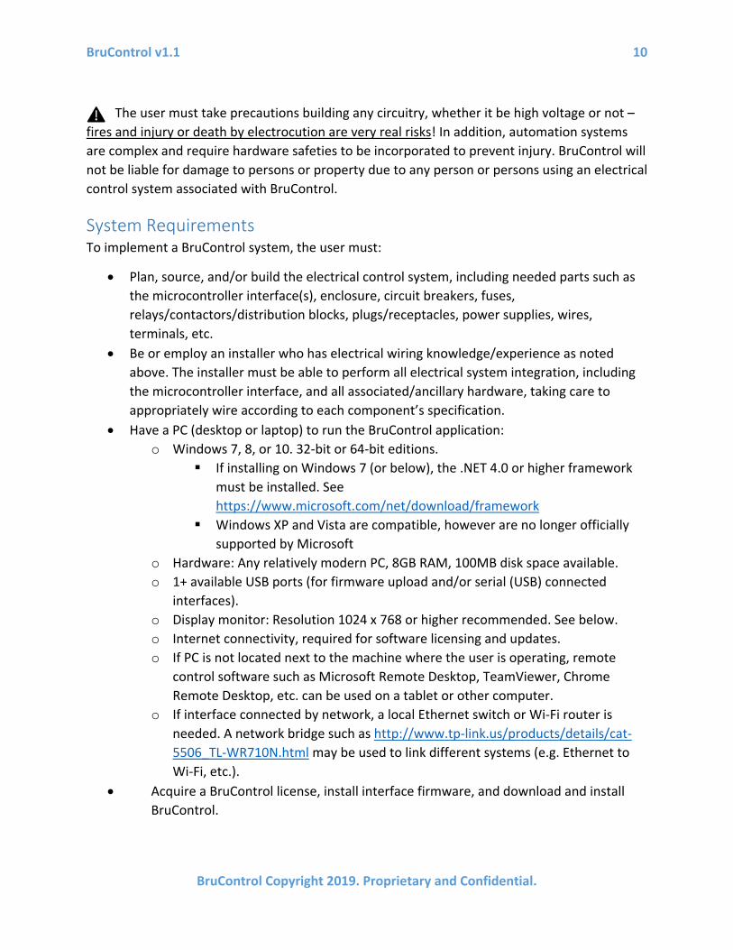
The user must take precautions building any circuitry, whether it be high voltage or not – fires and injury or death by electrocution are very real risks! In addition, automation systems are complex and require hardware safeties to be incorporated to prevent injury. BruControl will not be liable for damage to persons or property due to any person or persons using an electrical control system associated with BruControl.
System Requirements To implement a BruControl system, the user must:
• Plan, source, and/or build the electrical control system, including needed parts such as the microcontroller interface(s), enclosure, circuit breakers, fuses, relays/contactors/distribution blocks, plugs/receptacles, power supplies, wires, terminals, etc.
• Be or employ an installer who has electrical wiring knowledge/experience as noted above. The installer must be able to perform all electrical system integration, including the microcontroller interface, and all associated/ancillary hardware, taking care to appropriately wire according to each component’s specification.
• Have a PC (desktop or laptop) to run the BruControl application: o Windows 7, 8, or 10. 32-bit or 64-bit editions.
If installing on Windows 7 (or below), the .NET 4.0 or higher framework must be installed. See https://www.microsoft.com/net/download/framework
Windows XP and Vista are compatible, however are no longer officially supported by Microsoft
o Hardware: Any relatively modern PC, 8GB RAM, 100MB disk space available. o 1+ available USB ports (for firmware upload and/or serial (USB) connected
interfaces). o Display monitor: Resolution 1024 x 768 or higher recommended. See below. o Internet connectivity, required for software licensing and updates. o If PC is not located next to the machine where the user is operating, remote
control software such as Microsoft Remote Desktop, TeamViewer, Chrome Remote Desktop, etc. can be used on a tablet or other computer.
o If interface connected by network, a local Ethernet switch or Wi-Fi router is needed. A network bridge such as http://www.tp-link.us/products/details/cat-5506_TL-WR710N.html may be used to link different systems (e.g. Ethernet to Wi-Fi, etc.).
• Acquire a BruControl license, install interface firmware, and download and install BruControl.

BruControl v1.1 11
BruControl Copyright 2019. Proprietary and Confidential.
BruControl is intended to be touch-screen friendly. For example, there are no mouse right-clicks. The buttons, fonts, and menus are large to accommodate touch, but the unintended consequence of overfilling a screen can happen on smaller resolution displays. Therefore, a display with adequate vertical screen resolution and display scaling must be selected. The vertical resolution is the second number in a screen resolution format. For example, 1920 x 1080 (or 1080p) is 1080. In this table, any display scale less than the maximum shown is OK. Resolution/scale combinations that indicate ‘OK w/opt’ means for the application to be properly viewed, either the taskbar must be set to auto-hide, or the application’s display scaling must be disabled.
Vertical Resolution Maximum Scale
allowable Result 1080 125% OK
1080 150% OK w/opt
1050 125% OK
1050 150% OK w/opt
1024 125% OK w/opt
1000 125% OK w/opt
960 125% OK w/opt
900 125% OK w/opt
768 100% OK w/opt
To auto-hide the task bar, right-click the Taskbar, select Settings, then turn on ‘Automatically hide the taskbar’. To disable display scaling, right-click the BruControl.exe or shortcut file, select ‘Properties’…’Compatibility’ tab... ‘Settings’… check ‘Disable display scaling on high DPI settings’.

BruControl v1.1 12
BruControl Copyright 2019. Proprietary and Confidential.
Quick Start
Complete instructions for interface selection, wiring, firmware setup, and application usage follow. However, for experienced or technical users, this Quick Start guide may facilitate initial setup.
1. Review the system requirements for your computer in System Requirements above. 2. Follow Interface Firmware Installation and Setup steps. 3. Purchase a BruControl license at brucontrol.com/buy. You will receive an email within
12 hours when your license is authorized. 4. Follow Application Setup steps. 5. Once BruControl is running, open the Settings (gear icon). Select the ‘Interfaces’ tab.
Select ‘ADD…’ and fill-in or select the appropriate settings for the interface. Select ‘OK’ and close the Settings.
6. Create a test device be selecting the Menu icon, then ‘ADD DEVICE’. Select the Interface name and select the port # of the onboard LED (per the Interface Wiring Map for your interface). Select ‘Digital Output’ as the device type.
7. Enable the device. Select OK, then select the device element to toggle it’s ON and OFF state. The LED onboard the interface should illuminate and turn off accordingly.
8. You are ready to continue setting up your BruControl system!
BruControl v1.1 13
BruControl Copyright 2019. Proprietary and Confidential.
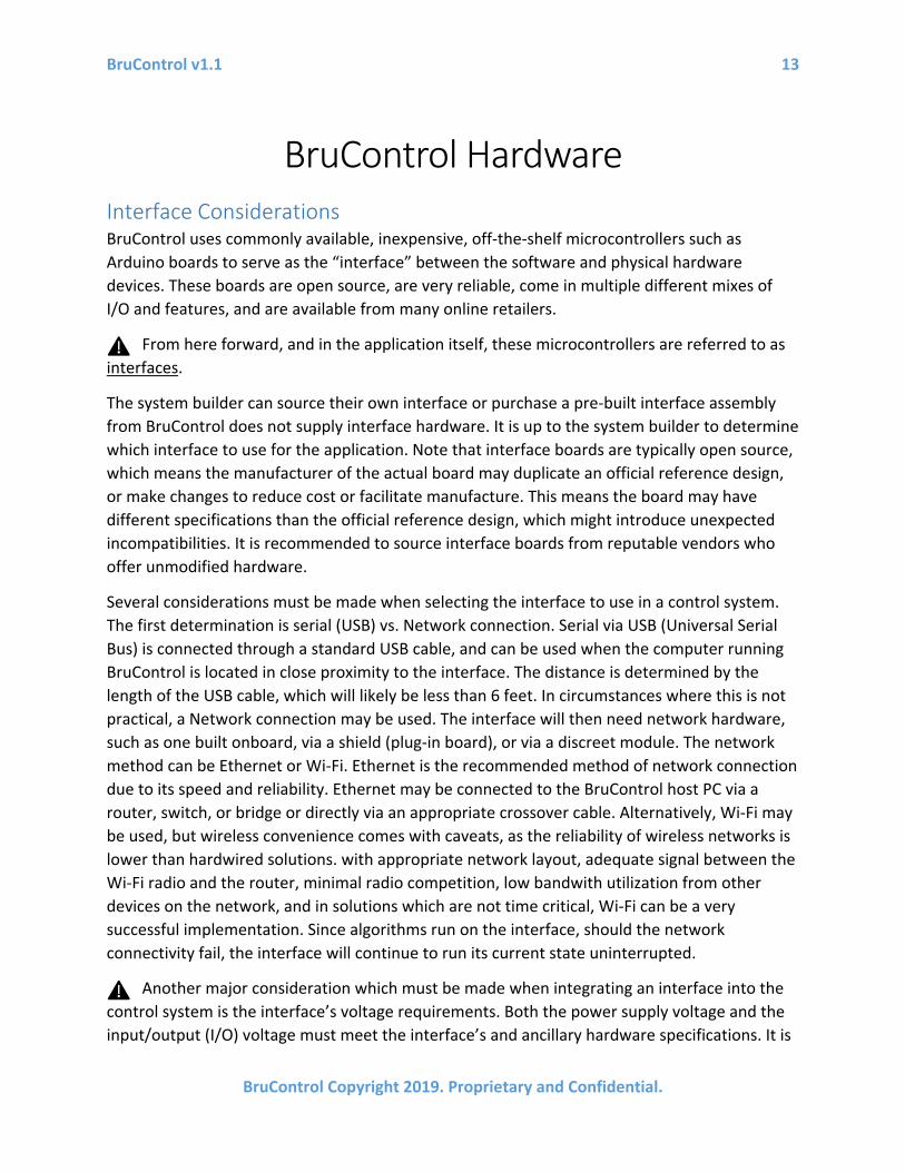
BruControl Hardware Interface Considerations BruControl uses commonly available, inexpensive, off-the-shelf microcontrollers such as Arduino boards to serve as the “interface” between the software and physical hardware devices. These boards are open source, are very reliable, come in multiple different mixes of I/O and features, and are available from many online retailers.
From here forward, and in the application itself, these microcontrollers are referred to as interfaces.
The system builder can source their own interface or purchase a pre-built interface assembly from BruControl does not supply interface hardware. It is up to the system builder to determine which interface to use for the application. Note that interface boards are typically open source, which means the manufacturer of the actual board may duplicate an official reference design, or make changes to reduce cost or facilitate manufacture. This means the board may have different specifications than the official reference design, which might introduce unexpected incompatibilities. It is recommended to source interface boards from reputable vendors who offer unmodified hardware.
Several considerations must be made when selecting the interface to use in a control system. The first determination is serial (USB) vs. Network connection. Serial via USB (Universal Serial Bus) is connected through a standard USB cable, and can be used when the computer running BruControl is located in close proximity to the interface. The distance is determined by the length of the USB cable, which will likely be less than 6 feet. In circumstances where this is not practical, a Network connection may be used. The interface will then need network hardware, such as one built onboard, via a shield (plug-in board), or via a discreet module. The network method can be Ethernet or Wi-Fi. Ethernet is the recommended method of network connection due to its speed and reliability. Ethernet may be connected to the BruControl host PC via a router, switch, or bridge or directly via an appropriate crossover cable. Alternatively, Wi-Fi may be used, but wireless convenience comes with caveats, as the reliability of wireless networks is lower than hardwired solutions. with appropriate network layout, adequate signal between the Wi-Fi radio and the router, minimal radio competition, low bandwith utilization from other devices on the network, and in solutions which are not time critical, Wi-Fi can be a very successful implementation. Since algorithms run on the interface, should the network connectivity fail, the interface will continue to run its current state uninterrupted.
Another major consideration which must be made when integrating an interface into the control system is the interface’s voltage requirements. Both the power supply voltage and the input/output (I/O) voltage must meet the interface’s and ancillary hardware specifications. It is

BruControl v1.1 14
BruControl Copyright 2019. Proprietary and Confidential.
critical that the appropriate voltages are implemented when designing and building a system, otherwise component failures will occur. Some models run on 5VDC power and logic, some are 3.3VDC logic, and some are 3.3VDC logic but are 5VDC tolerant. 5VDC is a common standard for ancillary hardware, whereas 3.3V is not. For example, relay boards exist in 5V versions, though most will switch with a 3.3V input signal. Analog sensors typically range 0-5V, so these should be evaluated carefully. The interface should generally be powered via the VIN pin or DC jack so that the internal regulator is used as a layer of filtering, but can be powered via the USB port. In either circumstance, it is important a clean, regulated supply voltage is used.
Another consideration is ancillary hardware requirements current needs. The pins from the interfaces can source (provide positive voltage) or sink (provide a path to ground), but have limited voltages and currents they can accommodate. For example, the Arduino MEGA has a per-pin limit of 15mA, but it is recommended devices which only use 5mA or less are implemented. In this example, a solid-state relay (SSR) should be selected which only requires 5mA or less at 5VDC to be triggered. All interfaces have per pin and maximum total current limitations – the manufacturers specification sheet should be consulted.
Certain interfaces have memory in them which allows for settings to be stored permanently, whereas others only have temporary storage. BruControl uses this memory to store settings for interfaces connecting via default Network. Interfaces with permanent memory will retain their network settings each time the firmware is installed or updated, whereas interfaces with temporary storage will require their settings to be re-entered each time their firmware is installed or updated (identified by “Until new FW” in the table below). Note that in both circumstances, the interface can be powered off and on without losing its network settings.
A Screw Shield is recommended for mounting and ease/reliability of wiring termination. Note that some screw shields do not allow for an additional shield to be attached, which would prevent a Network or other I/O shield from being used. BruControl support or the BruControl website can help system builders source appropriate shields and combinations.
See the Appendix for the overview of interfaces, specifications, limitations, combinations, etc.
Device Types BruControl can address many different device types. In most cases, supporting hardware will be required to integrate them into the system. For example, a motor will need to be powered through a relay circuit to convert the low power signal from the interface into a high-power switch. The “input” or “output” direction refers to the interface’s perspective. The types of physical devices that BruControl can address include:
1. Digital Outputs – these are commanded on/off devices such as motors, heaters, refrigeration compressors, motorized valves, solenoids, relays, etc.
2. Digital Inputs – these are the read states of on/off switches, sensors, contacts, etc.

BruControl v1.1 15
BruControl Copyright 2019. Proprietary and Confidential.
3. PWM Outputs (Analog Outputs) – these are commanded variable or proportional devices which respond to different command levels for a range of performance. These include proportional valves, pumps, actuators, etc. Specifically, PWM can control motors, lights, heaters, etc. by reducing the net power to those devices. PWM can be converted into an Analog Output via additional circuitry such as a RC low-pass filter.
4. Analog Inputs – these are the read voltages of variable or proportional sensors such as pressure, temperature (analog or thermistor), flow, etc.
5. Counter Inputs – these are read high-speed pulsed proportional sensors such as encoders or hall effect sensors.
6. Special temperature sensors – these are read variable sensors for measuring temperature and include Resistive Temperature Devices (RTDs), or 1-wire temperature sensors.
7. Special device sensors – these sensors provide data from particular devices used in processing applications, like electronic hydrometers.
Interface Wiring Maps Once an interface is selected, it will need to be integrated into the control system. Each of the interface’s pins can support specific Device Types (noted above). Therefore, each physical device must be wired to a suitable input or output type. The types (and corresponding letter codes) are Digital Input or Output (D), PWM Output/Analog Output (P), Analog Input (A), Counter Input (C), and special temperature sensors RTDs (R) and 1-wire (O).
There is a different Interface Wiring Map for each interface and each firmware that is installed. The variations in firmware include connection types (Serial [USB], Ethernet Network, Wi-Fi Network, or Yun Network), and whether it is capable of interfacing with RTD boards (for use with RTD sensors).
Once the appropriate interface/firmware combination is selected, the interface should be wired according to that column. Each interface pin will show the letter codes which reflect the types of devices that can be wired to it. See the Interface Wiring Maps section of the website for current Interface Wiring Maps.
Control System Considerations Ancillary electronic hardware are the components the interface is integrated in to create the complete control system. As noted above, the wiring of the ancillary electronic hardware is a critical portion of the control system, and doing so incorrectly can pose danger to persons or property, potentially causing injury or death! A proper schematic should always be followed when wiring a control system. Appropriate wire size, termination, and components for the task must be incorporated. Proper wiring techniques and standards should be followed. Most importantly, upstream protective circuitry must be incorporated and meet building code

BruControl v1.1 16
BruControl Copyright 2019. Proprietary and Confidential.
specifications. Protective circuitry includes breakers and/or fuses placed at each branch circuit. A GFI / GCFI should be included for any control system involving liquid or any possibility for alternate ground paths.
In systems where high voltage, high power, or high energy, or high strength devices (HV) are used, or where downstream devices potentially interface with human contact, several considerations should be made. First, it is recommended a two-stage interrupt is employed. For example, the first stage would be switch which powers the control main power (either directly or via contactor) should be activated first. This circuit powers low voltage devices, such as the BruControl interface’s DC power supply, but does not enable HV electronic components or devices. This ensures that the control system is properly running and prepared before allowing high voltage devices to become activated. A second switch (interlock or E-Stop, for example) can then be activated to allow those devices to be powered. This second switch should be manually controlled, not via the interface software control, but there may be circumstances where this is possible.
When designing and wiring a BruControl Interface, the appropriate Interface Wiring Map should be selected and followed. These maps indicate which device types can be wired to which interface pins. Each map will depend on the type of downstream hardware that is being implemented and the firmware which is installed on the interface.
When testing and debugging a new BruControl system, it should be performed with the low voltage circuitry first, and the HV side interlocked or de-powered. Automated machinery can be very unpredictable, so a stepwise testing methodology should be employed to ensure each subsystem is functioning as expected.
Do not perform “production runs” without conducting simulated runs prior. As with automation hardware, automation scripts will have bugs and/or perform in unexpected or unanticipated ways. It is critical that the builder test with source materials that can afford to be wasted prior to using real materials in a product environment. For example, for a Brewery, a water run should be performed before initiating an actual brew.
Interface Setup To prepare an interface for use with BruControl, firmware (software which runs on the microcontroller) must first be installed into the interface. Typically, interface firmware is created and uploaded using an integrated development environment (IDE). For those without programming or microcontroller experience, this is a complicated process of learning, writing, uploading, testing, re-writing, etc. BruControl’s solution removes this complexity by creating a firmware install and setup process which does not require any software installation.
See the Interface Preparation and Interface Firmware Overview and Setup sections of the Appendix for the specific interface being used.
BruControl v1.1 17
BruControl Copyright 2019. Proprietary and Confidential.
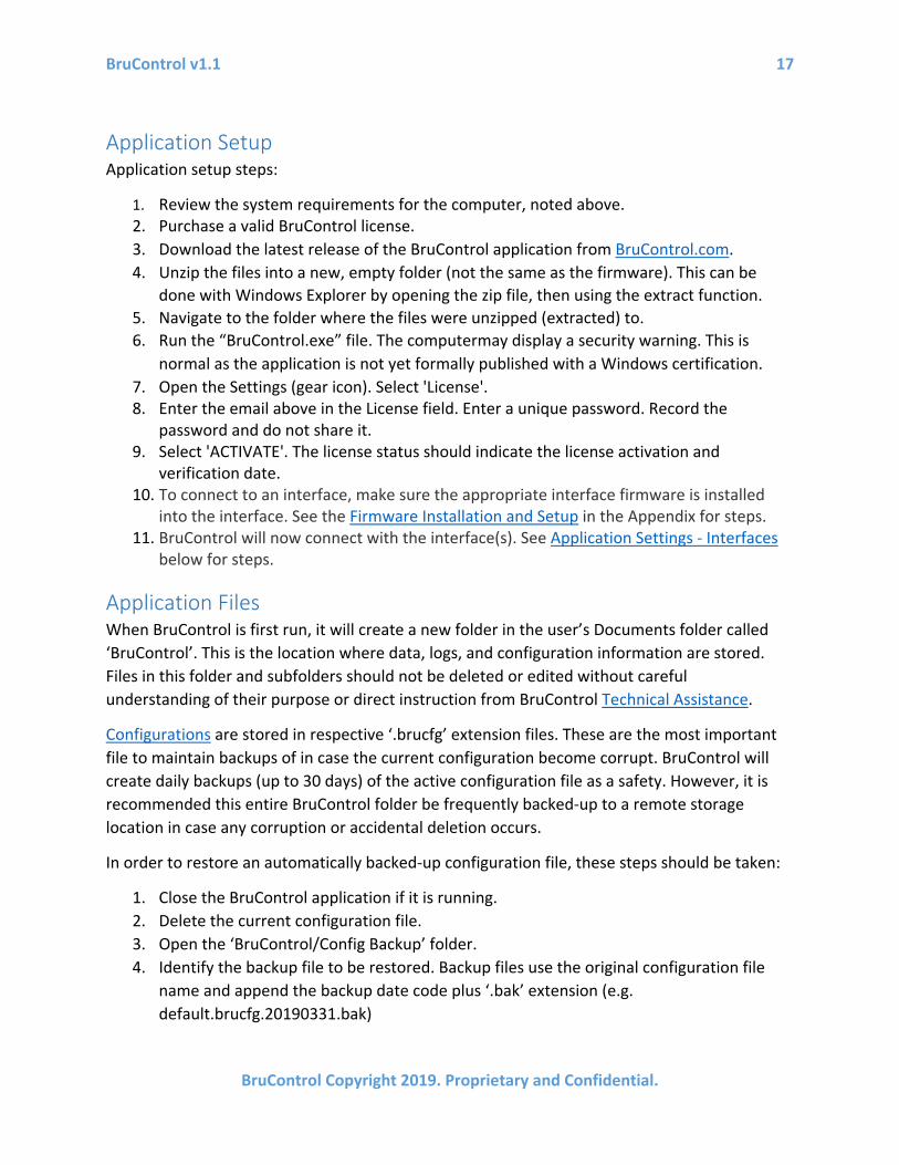
Application Setup Application setup steps:
1. Review the system requirements for the computer, noted above. 2. Purchase a valid BruControl license. 3. Download the latest release of the BruControl application from BruControl.com. 4. Unzip the files into a new, empty folder (not the same as the firmware). This can be
done with Windows Explorer by opening the zip file, then using the extract function. 5. Navigate to the folder where the files were unzipped (extracted) to. 6. Run the “BruControl.exe” file. The computermay display a security warning. This is
normal as the application is not yet formally published with a Windows certification. 7. Open the Settings (gear icon). Select 'License'. 8. Enter the email above in the License field. Enter a unique password. Record the
password and do not share it. 9. Select 'ACTIVATE'. The license status should indicate the license activation and
verification date. 10. To connect to an interface, make sure the appropriate interface firmware is installed
into the interface. See the Firmware Installation and Setup in the Appendix for steps. 11. BruControl will now connect with the interface(s). See Application Settings - Interfaces
below for steps.
Application Files When BruControl is first run, it will create a new folder in the user’s Documents folder called ‘BruControl’. This is the location where data, logs, and configuration information are stored. Files in this folder and subfolders should not be deleted or edited without careful understanding of their purpose or direct instruction from BruControl Technical Assistance.
Configurations are stored in respective ‘.brucfg’ extension files. These are the most important file to maintain backups of in case the current configuration become corrupt. BruControl will create daily backups (up to 30 days) of the active configuration file as a safety. However, it is recommended this entire BruControl folder be frequently backed-up to a remote storage location in case any corruption or accidental deletion occurs.
In order to restore an automatically backed-up configuration file, these steps should be taken:
1. Close the BruControl application if it is running. 2. Delete the current configuration file. 3. Open the ‘BruControl/Config Backup’ folder. 4. Identify the backup file to be restored. Backup files use the original configuration file
name and append the backup date code plus ‘.bak’ extension (e.g. default.brucfg.20190331.bak)

BruControl v1.1 18
BruControl Copyright 2019. Proprietary and Confidential.
5. Copy the selected folder and paste it in the ‘BruControl’ folder. Delete the date code and ‘.bak’ extension to leave a proper configuration file extension of ‘.brucfg’.
6. Start the BruControl application and select the appropriate configuration matching the restored file if necessary.
BruControl v1.1 19
BruControl Copyright 2019. Proprietary and Confidential.
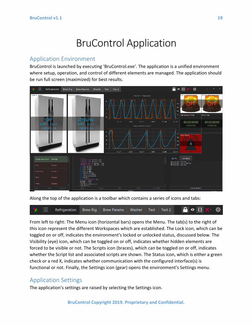
BruControl Application Application Environment BruControl is launched by executing ‘BruControl.exe’. The application is a unified environment where setup, operation, and control of different elements are managed. The application should be run full screen (maximized) for best results.
Along the top of the application is a toolbar which contains a series of icons and tabs:
From left to right: The Menu icon (horizontal bars) opens the Menu. The tab(s) to the right of this icon represent the different Workspaces which are established. The Lock icon, which can be toggled on or off, indicates the environment’s locked or unlocked status, discussed below. The Visibility (eye) icon, which can be toggled on or off, indicates whether hidden elements are forced to be visible or not. The Scripts icon (braces), which can be toggled on or off, indicates whether the Script list and associated scripts are shown. The Status icon, which is either a green check or a red X, indicates whether communication with the configured interface(s) is functional or not. Finally, the Settings icon (gear) opens the environment’s Settings menu.
Application Settings The application’s settings are raised by selecting the Settings icon.
BruControl v1.1 20
BruControl Copyright 2019. Proprietary and Confidential.
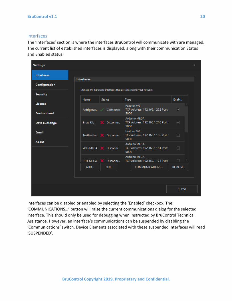
Interfaces The ‘Interfaces’ section is where the interfaces BruControl will communicate with are managed. The current list of established interfaces is displayed, along with their communication Status and Enabled status.
Interfaces can be disabled or enabled by selecting the ‘Enabled’ checkbox. The ‘COMMUNICATIONS…’ button will raise the current communications dialog for the selected interface. This should only be used for debugging when instructed by BruControl Technical Assistance. However, an interface’s communications can be suspended by disabling the ‘Communications’ switch. Device Elements associated with these suspended interfaces will read ‘SUSPENDED’.
BruControl v1.1 21
BruControl Copyright 2019. Proprietary and Confidential.
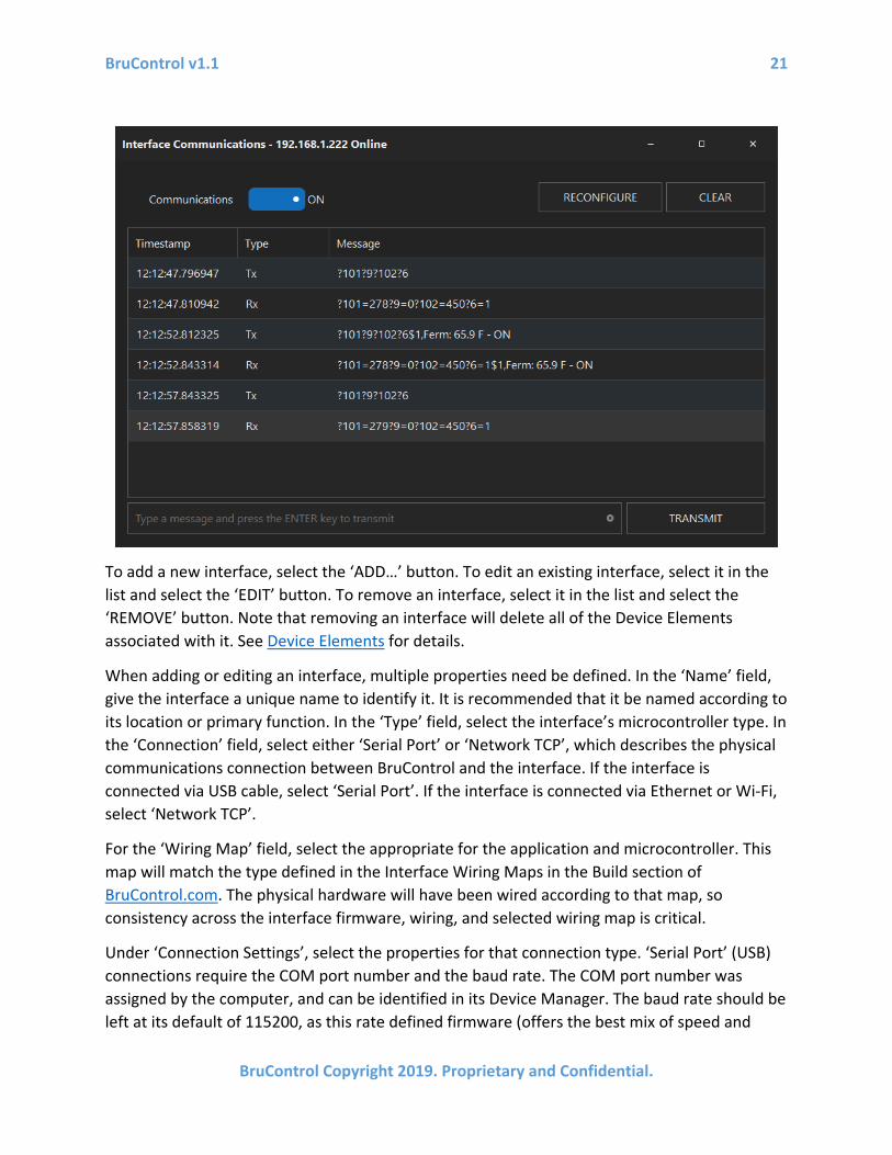
To add a new interface, select the ‘ADD…’ button. To edit an existing interface, select it in the list and select the ‘EDIT’ button. To remove an interface, select it in the list and select the ‘REMOVE’ button. Note that removing an interface will delete all of the Device Elements associated with it. See Device Elements for details.
When adding or editing an interface, multiple properties need be defined. In the ‘Name’ field, give the interface a unique name to identify it. It is recommended that it be named according to its location or primary function. In the ‘Type’ field, select the interface’s microcontroller type. In the ‘Connection’ field, select either ‘Serial Port’ or ‘Network TCP’, which describes the physical communications connection between BruControl and the interface. If the interface is connected via USB cable, select ‘Serial Port’. If the interface is connected via Ethernet or Wi-Fi, select ‘Network TCP’.
For the ‘Wiring Map’ field, select the appropriate for the application and microcontroller. This map will match the type defined in the Interface Wiring Maps in the Build section of BruControl.com. The physical hardware will have been wired according to that map, so consistency across the interface firmware, wiring, and selected wiring map is critical.
Under ‘Connection Settings’, select the properties for that connection type. ‘Serial Port’ (USB) connections require the COM port number and the baud rate. The COM port number was assigned by the computer, and can be identified in its Device Manager. The baud rate should be left at its default of 115200, as this rate defined firmware (offers the best mix of speed and

BruControl v1.1 22
BruControl Copyright 2019. Proprietary and Confidential.
reliability), unless special versions are used. ‘Network TCP’ (Ethernet or Wi-Fi) connections require the interface’s IP address. This is either assigned manually or by the router via DHCP, which was selected when the interface firmware was set up. Port 5000 is the default port and is defined as such in the firmware. See Interface Setup for details.
For ‘Refresh Interval’ select the amount of time appropriate to that interface. See Interface Communication for details.
‘Response Timeout’ refers to the amount of time BruControl will wait to receive a response from the interface before flagging the communications error and attempting to reconnect. The default of 3 seconds is adequate for local wired connections such as serial (USB) and Ethernet. It should be increased to 5 or more for Wi-Fi connections or where the interface is on a WAN (Wide Area Network).
Configuration BruControl uses Configurations to define the properties of the entire Environment, including the interfaces, Workspaces, Elements, Scripts, etc. This allows for one application to work with entirely different systems. It can also be used to differentiate production from test machines or
BruControl v1.1 23
BruControl Copyright 2019. Proprietary and Confidential.
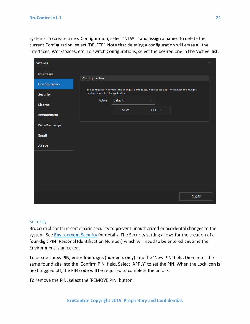
systems. To create a new Configuration, select ‘NEW…’ and assign a name. To delete the current Configuration, select ‘DELETE’. Note that deleting a configuration will erase all the interfaces, Workspaces, etc. To switch Configurations, select the desired one in the ‘Active’ list.
Security BruControl contains some basic security to prevent unauthorized or accidental changes to the system. See Environment Security for details. The Security setting allows for the creation of a four-digit PIN (Personal Identification Number) which will need to be entered anytime the Environment is unlocked.
To create a new PIN, enter four digits (numbers only) into the ‘New PIN’ field, then enter the same four digits into the ‘Confirm PIN’ field. Select ‘APPLY’ to set the PIN. When the Lock icon is next toggled off, the PIN code will be required to complete the unlock.
To remove the PIN, select the ‘REMOVE PIN’ button.

BruControl v1.1 24
BruControl Copyright 2019. Proprietary and Confidential.
License BruControl uses a license system to ensure authorized installations are utilized. This system requires that the host computer access a remote web server to confirm authorization. The host computer must be connected to the internet for initial activation. Thereafter, BruControl will confirm authorization every few hours. If authorization cannot be achieved because the host computer is not connected to the internet, it will continue to function for 30 days before requiring authorization confirmation.
The first step in a new installation is to activate the license. To do so, enter the credentials of the licensee, including the ‘Email’ and ‘Password’ in their respective fields, then select the ‘ACTIVATE’ button. The license will be verified, and the ‘License Status’ will be updated to reflect its status and level.
Levels include ‘BASIC’, ‘ADVANCED’, and ‘PROFESSIONAL’. Ensure the activated license level matches the purchased or acquired license.

BruControl v1.1 25
BruControl Copyright 2019. Proprietary and Confidential.
The ‘BASIC’ license allows BruControl to control one Serial Interface. The ‘ADVANCED’ license adds the ability to control unlimited Serial and Network connected Interfaces. The ‘PROFESSIONAL’ license adds the ability for third-party applications to communicate with the BruControl application via a Data Exchange Protocol.
To release the license for installation on another computer, contact BruControl Technical Assistance.
Environment The Environment setting allows for customization of the application’s appearance. The general coloring, fonts, button types, etc. can be globally changed using the ‘Theme’ selection. Light, dark, and various other themes are available. It is recommended to use ‘The Bezier’ Theme and any chosen sub-theme, as this will provide the best performance on high-resolution monitors.
The Element Grid Size setting determines a grid upon which the Element’s location, width, and height are located upon. This is known as “Snap to Grid”. This helps the user align Elements and

BruControl v1.1 26
BruControl Copyright 2019. Proprietary and Confidential.
create a uniform layout or array of elements. The default is ‘10x10’ Pixels. Setting to ‘1x1 Pixels’ effectively turns off this function.
Elements have a default appearance, which is defined here. Each new Element will be created with these default settings. To change Elements’ default appearance, select the ‘ELEMENT APPEARANCE…’ button. The explanation for each of the fields in ‘Appearance Settings’ can be found in Element Appearance.
The application can be minimized to the Windows system tray rather than being minimized to the Windows task bar. This is commonly done in server-type applications to prevent users from accidentally closing the application. To enable this function, enable it via the ‘Minimize to system tray’ switch.
Data Exchange BruControl contains a function to facilitate data exchange with other applications. It utilizes a server type HTTP service to communicate the values of certain Global variables. In order to for

BruControl v1.1 27
BruControl Copyright 2019. Proprietary and Confidential.
this service to function correctly, the URL reservation must be established on the host computer. To do this, select ‘RESERVE URL’. Then to enable the service, set the ‘Service’ switch to ‘Enabled’. See Data Exchange Protocol for utilization of this function. Note: The Data Exchange Service requires a PROFESSIONAL’ level license.
Email BruControl contains an Email Notification system which will allow the application to send a notification email in certain circumstances, primarily when an Alarm is activated.
To enable this notification system, turn the ‘Email Notifications’ switch on. Then add one or more email addresses to be notified using the ‘ADD…’ button. The selected email address in the list can be removed with the ‘REMOVE’ button.
Establish the sending email account using the ‘ACCOUNT SETTINGS…’ button. In this box, select a pre-configured email server by selecting one in the list, or use the ‘Custom’ entry to provide

BruControl v1.1 28
BruControl Copyright 2019. Proprietary and Confidential.
discreet server settings. When using ‘Custom’, the ‘SMTP Host’, ‘SMTP Port’, and ‘Use SSL’ settings must be configured.
Enter the email account credentials for the selected account in the ‘Username’ and ‘Password’. Ensure the entire email address is used for the ‘Username’. Select ‘SEND TEST MESSAGE…’ to test the email account is correct and the Email Notification system is functioning.

BruControl v1.1 29
BruControl Copyright 2019. Proprietary and Confidential.
About
The ‘About’ tab displays the current version and build number. This should be provided when contacting BruControl Technical Support.
Touch Keypad Many numerical fields throughout the application contain a built-in touch keypad to facilitate data entry. These fields are demarked by a 9-dot matrix icon at the right end of the field. To access the keypad, select the icon.
The keypad contains normal number buttons, plus backspace and clear buttons. ‘OK’ and ‘CANCEL’ buttons will keep or ignore the entry, respectively.

BruControl v1.1 30
BruControl Copyright 2019. Proprietary and Confidential.
Interface Communication BruControl communicates with each interface using messages to command and/or query its devices on a timed basis. BruControl uses a queuing system, so that messages are sent only when they need to be and the communication timer elapses. This timer is called the Refresh Interval, and is set by the interface’s connection settings. See Application Settings/Interfaces for details. By default, this interval is every 1 second, but can be made faster or slower. For serial (USB) and Ethernet connections, this default is recommended. For Wi-Fi connections, 1 – 3 seconds are recommended.
The devices connected through that interface are then communicated with individually according to their Refresh Multiple. The Refresh Multiple is set in a device’s properties (device ‘i’ icon… General tab… Element… Refresh Multiple) and is 1 by default. Multiplying the interface’s Refresh Interval by a specific device’s Refresh Multiple results in its actual refresh interval. For example, if an interface’s Refresh Interval is 3 seconds and its device’s Refresh Multiple is 2, the refresh interval for that device is 6 seconds. This means that updates to or queries from that device will occur every six seconds.
Device’s statuses and values are updated according to these periods, so it is important to keep these in mind when expecting device’s values to update. Scripts may need be written to accommodate these delays. For example, a time delay may need to be introduced in the Script if a device output is contingent upon another device’s value.
Note that interface internal algorithms like Hysteresis, PID, or Deadband Outputs are not affected by this schedule. Only the communication between the interface and BruControl is.

BruControl v1.1 31
BruControl Copyright 2019. Proprietary and Confidential.
The benefit to a higher Refresh Interval and/or Refresh Multiple is reduced communication overhead, and potentially faster interface execution (depending on its calculation load and CPU speed), and should be adjusted according to the control system’s reporting needs and connection quality. For example, a refrigeration unit need not report its temperature to BruControl but every 30 seconds or more, whereas a fast-changing heating vessel’s temperature device may need be reported every 1 second. Increasing these settings can help reduce network traffic (slightly) and possibly increase reliability.
Workspaces
A Workspace is an “open canvas” where the user can add, organize, and manage different graphical “Elements”. The area under the toolbar is the current Workspace area. Workspaces are highly flexible, allowing for an easily customized layouts per the user’s needs. The environment can host multiple Workspaces. Each Workspace can represent multiple combined control systems, a single control system, or just a sub-section of a control system. Each Workspace can hold as many or as few Elements as desired, and Elements can be moved anywhere in the Workspace. Elements can also be sized and formatted as desired to create unique appearances.
Workspaces are created via Menu… Add Workspace. The current Workspace is shown by the highlighted tab in the toolbar, and other Workspaces can be selected there. Dragging a Workspace tab left or right reorganizes the tab order. The current Workspace can be renamed via Menu… Rename Workspace. The current Workspace can be wiped clean of all its elements via Menu… Clear Workspace. Finally, the current Workspace can be deleted via Menu… Delete Workspace.
When a Workspace is deleted, its Elements are also deleted.

BruControl v1.1 32
BruControl Copyright 2019. Proprietary and Confidential.
The current Workspace can be further customized by adding a background image via Menu… Background Image… then Browse… to select .JPG or .PNG image to display. The Width and Height options allow for size customization. To fill the whole workspace, it is recommended to enter the monitor’s display resolution. To remove the selected image, click the X icon in the file selection field. The image is automatically scaled to fill the Workspace.
Elements Elements represent different components of the control system, and each displays real time information related to its function. This serves as the HMI (Human-Machine Interface). The Elements can be placed, moved, and sized, and formatted as desired.
Element’s properties are accessed by selecting its information icon, represented by a circular ‘i’ in its upper right corner. The Element can be moved by dragging this icon. In addition, the Element can be resized by dragging the resize indicator in its lower right corner. Elements will align according to the grid established in Settings… Environment. Both the information and resize icons are only available when the environment is unlocked. Elements can be moved across Workspaces using the ‘WORKSPACE…’ button in its properties dialog. In addition, Elements may be deleted using the ‘DELETE’ button in its properties dialog.
BruControl will automatically assign a name when an Element is created, but these names can be changed.
Elements must be given unique names, otherwise conflicts will occur.
The Element types are as follows:
1. Device Elements – Graphical representations for control and reporting of physical devices.
2. Timer Elements – Software timers which can be used to monitor or control processes in the control system.
3. Alarm Elements – Software alarms activated and deactivated manually or automatically to alert a user, depending on control system conditions.
4. Graph Elements – Line graphs which plot data to present values over time. 5. Global Elements – Software elements which hold and display user data or values. 6. Button Elements – Software elements which allow the user to generate inputs to the
control system. 7. Switch Elements – Software elements which allow the user to generate an on/off input
to the control system. 8. Inspector Elements – Software elements which display variables used in scripts.
BruControl v1.1 33
BruControl Copyright 2019. Proprietary and Confidential.
Environment Security When the environment is locked, elements cannot be edited, moved or resized. Workspaces cannot be edited or deleted and their tabs cannot be re-ordered. This is to prevent accidental or unauthorized changes to the control system. In order to unlock the environment, the user un-toggles the Lock icon, and enters the Pin Code if one is established in the Security tab of the Settings.
User Control Most Elements contain a property called ‘User Control’, which is set in their respective properties. Scripts also have a User Control property. This allows for the user to interact with pieces of the control system without inappropriately making global changes.
If User Control is disabled, the Element’s or Script’s control or value cannot be changed when the environment is locked. When this is enabled, the control or value can be changed even when the Environment is locked. User Control disabled by default.
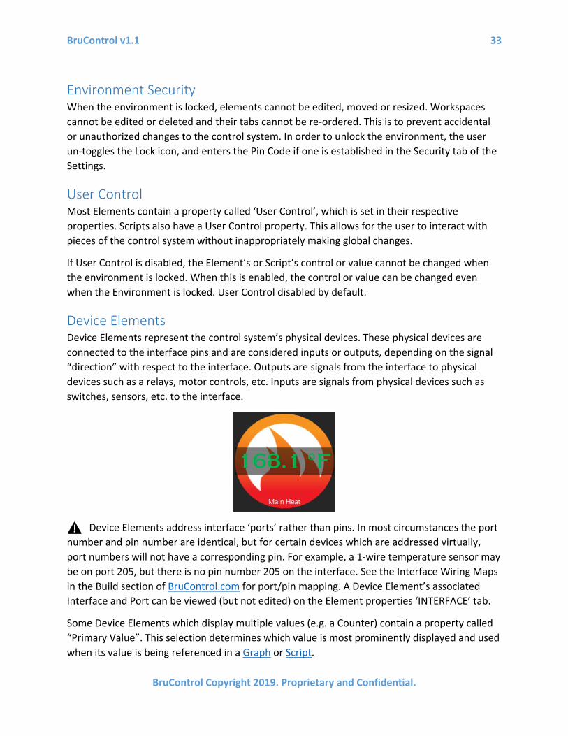
Device Elements Device Elements represent the control system’s physical devices. These physical devices are connected to the interface pins and are considered inputs or outputs, depending on the signal “direction” with respect to the interface. Outputs are signals from the interface to physical devices such as a relays, motor controls, etc. Inputs are signals from physical devices such as switches, sensors, etc. to the interface.
Device Elements address interface ‘ports’ rather than pins. In most circumstances the port number and pin number are identical, but for certain devices which are addressed virtually, port numbers will not have a corresponding pin. For example, a 1-wire temperature sensor may be on port 205, but there is no pin number 205 on the interface. See the Interface Wiring Maps in the Build section of BruControl.com for port/pin mapping. A Device Element’s associated Interface and Port can be viewed (but not edited) on the Element properties ‘INTERFACE’ tab.
Some Device Elements which display multiple values (e.g. a Counter) contain a property called “Primary Value”. This selection determines which value is most prominently displayed and used when its value is being referenced in a Graph or Script.

BruControl v1.1 34
BruControl Copyright 2019. Proprietary and Confidential.
Create a new Device Element by selecting Menu… Add Device. In the New Device box, select the name of the Interface where the device is wired, select the port, and the select the type of device is physically wired to that port.
The physical devices represented by its Device Element are not actually addressed by the interface until the Device Element enabled. When a Device Element is disabled, it is essentially idle, and it will not be controllable or present any value. To enable a device, open the Device Element’s properties and change the ‘Enabled’ switch to on. Disabled devices will report ‘DISABLED’.
Multiple Device Elements can be configured to address an individual port, but not simultaneously. Enabling a Device Element which addresses a particular port will automatically disable other enabled Device Elements which address the same port.
Digital Input These are binary devices which read the voltage of the interface’s pin. These types of devices are noted above under Device Types, list #2. The state is presented as the Element’s value and will either be ON or OFF depending if the voltage is high or low. High is above ~65% and low is below ~30% of the interface’s operating voltage (approximate values, depends on the interface’s CPU).
Digital Inputs have no User Control, as they are read-only Elements.
The only specific property for a Digital Input is the ‘Active Low’ switch. This setting is OFF by default, which means that a high voltage equates to an ON state. If this property is enabled, the setting will become active low, meaning that a low voltage equates to the ON state of the Device Element. Note that this setting is not strictly an inversion in the application. It causes the interface to enable a pull-up resistor in the pin, which will ensure the voltage reads high voltage unless a ground (low) signal is applied.

BruControl v1.1 35
BruControl Copyright 2019. Proprietary and Confidential.
Counter Input These are devices which count the number and rate of voltage change cycles on the interface’s pin. These types of devices are noted above under Device Types, list #5. Each time the voltage changes from a high to a low voltage, the counter is incremented. See voltage definitions in Digital Input for details. Therefore, the Counter Input is measuring the number of pulses received on its respective pin. Both the total (total pulses) and rate (pulses per second) are presented as the Element’s values.
Counter Inputs have no User Control, as they are read-only elements.

BruControl v1.1 36
BruControl Copyright 2019. Proprietary and Confidential.
The only specific property for a Counter Input is the ‘Sampling Period’ field. This property controls the historic window of time that the rate is being calculated over. It is set to 1 second by default, but can be as long as 10 seconds. This property does not affect the pulses per second rate, but acts to smooth the values over time. For example, if this property were set to 5 seconds, the total number of pulses received over 5 seconds would be reported.
A Counter Input’s total value is maintained as long as the interface is powered. Its count limit is approximately 4.29 x 10⁹ (~4.3 billion), and when exceeded will revert to zero. To reset this value, disable the device and re-enable it, delayed by a period of time which is at least longer than the device’s refresh interval. This disable and enable sequence can be performed manually via the Counter Input Properties or via a script.

BruControl v1.1 37
BruControl Copyright 2019. Proprietary and Confidential.
Analog Input These are variable devices which read the voltage of the interface’s pin. These types of devices are noted above under Device Types, list #4. The value along a range proportional to the reference voltage is averaged and presented as the Element’s value. The number of divisions in the ranges will be commensurate with the interface’s Analog to Digital Converter (ADC) resolution, which is dependent on the interface’s CPU model (see Interface Overview in the Appendix). If an interface’s resolution is 10 bits (210 = 1024), the reported value along the range will be divided into 1024 steps, where 0 indicates 0 volts and 1023 indicates a voltage equal to or above reference voltage (typically either 5V or 3.3V, depending on the reference voltage and respective wiring). The reference voltage is typically the CPU voltage. Therefore, for example, with 1024 voltage divisions and a 5V reference voltage, the step from one reported value to the next represents an increase of approximately 4.9mV. See the Schematics section on BruControl’s website for details on wiring analog sensors.
Analog Inputs have no User Control, as they are read-only elements.
There are two specific properties for an Analog Input. The first is the ‘Avg Weight’ (average weight) field which has a range of 1 to 100 percent and a default of 25 percent, and the second is the ‘Poll Rate’ field which has a range of 250 to 25,000 milliseconds (25 seconds) and a default of 500 milliseconds. A new measurement, or “sample” of the voltage on the interface’s pin is taken continuously, according to the time interval of the ‘Poll Rate’. This sampling is independent of how often this device’s value is read by BruControl (determined by its actual refresh interval). That sample is then averaged into the a running average with the weight dictated by the ‘Avg Weight’.
This averaging is performed for digital smoothing of the samples, which functionally reduces noise common with analog devices and circuitry. Therefore, for example, with these default settings, a new analog voltage measurement will be taken twice a second, and the resulting average will be equal to 75% of the existing average and 25% of the new sample. If the current sample needs be displayed, the ‘Avg Weight’ should be set to 100%. See Analog Input Considerations for more information on filtering.

BruControl v1.1 38
BruControl Copyright 2019. Proprietary and Confidential.
SPI Sensor Input These are variable devices which read a RTD (Resistive Temperature Device) probe’s temperature via a separate board connected via SPI (Serial Peripheral Interconnect). See the Schematics section on BruControl’s website for details of these boards. These types of devices are noted above under Device Types, list #6. The value along a range proportional to the temperature is presented as the Element’s value. Note: SPI Sensor Inputs are available only when the associated Interface’s Settings have the correct Wiring Map selected (e.g. “With RTD).
SPI Sensor Inputs have no User Control, as they are read-only elements.

BruControl v1.1 39
BruControl Copyright 2019. Proprietary and Confidential.
There are two specific properties for a SPI Sensor Input. The first is the ‘Avg Weight’ (average weight) field which has a range of 1 to 100 percent and a default of 25 percent, and the second is the ‘Poll Rate’ field which has a range of 250 to 25,000 milliseconds (25 seconds) and a default of 500 milliseconds. A new measurement, or “sample” of the value of the SPI board is taken continuously, according to the time interval of the ‘Poll Rate’. This sampling is independent of how often this device’s value is read by BruControl (determined by its actual refresh interval). That sample is then averaged into the a running average with the weight dictated by the ‘Avg Weight’.
This averaging is performed for digital smoothing of the samples, which functionally reduces noise common with analog devices and circuitry. Therefore, for example, with these default settings, a new analog voltage measurement will be taken twice a second, and the resulting average will be equal to 75% of the existing average and 25% of the new sample. If the current sample needs be displayed, the ‘Avg Weight’ should be set to 100%. High impedance sensors such as RTDs are mildly prone to noise, so an average weight such as 75% or more can be used.
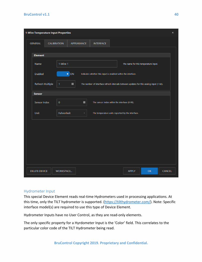
1-wire Temperature Input These are variable devices which read a 1-wire (DS18B20) sensor’s temperature. These types of devices are noted above under Device Types, list #6. The temperature of the device is presented as the Element’s value.
1-wire Temperature Inputs have no User Control, as they are read-only elements.
There are two specific properties for a 1-wire Temperature Input. The first is the ‘Sensor Index’, which has a range of 0-99, and the second is the reported value’s unit. When an interface is first powered, all the 1-wire sensors connected to it are enumerated, with each receiving a unique index, numbered from 0 upward. For example, if a system has three sensors, they will be assigned indexes 0, 1, and 2 respectively.
The Sensor Index is used to associate a Device Element to a specific sensor. The actual index will need be determined by trial and error, but once the index is selected, it will always be maintained, unless additional sensors are added or removed from the interface.
BruControl v1.1 40
BruControl Copyright 2019. Proprietary and Confidential.
Hydrometer Input This special Device Element reads real-time Hydrometers used in processing applications. At this time, only the TILT hydrometer is supported. (https://tilthydrometer.com/). Note: Specific interface model(s) are required to use this type of Device Element.
Hydrometer Inputs have no User Control, as they are read-only elements.
The only specific property for a Hyrdometer Input is the ‘Color’ field. This correlates to the particular color code of the TILT Hydrometer being read.

BruControl v1.1 41
BruControl Copyright 2019. Proprietary and Confidential.
Digital Output These are binary devices which command the interface’s pin to be a high or low voltage. These types of devices are noted above under Device Types, list #1. The state is presented as the Element’s state and will either be ON or OFF depending if the voltage is high or low. High is ~90% and low is ~10% of the interface’s operating voltage (approximate values, depends on the interface’s CPU). By default, when the Device Element is ON, the interface pin’s voltage is high (Active High).

BruControl v1.1 42
BruControl Copyright 2019. Proprietary and Confidential.
Digital Outputs have a property for User Control, as they are commanded elements. When the property is enabled or the environment is unlocked, selecting the Element’s ON or OFF value will invert its state. This can be used to quickly turn a device on or off. Digital Outputs can be turned ON or OFF permanently, or they may be automatically inverted after a defined period of time using the One-Shot function.
There are four specific properties for a Digital Output. The first is the ‘State’ switch, which is the state of the interface output. The second is the ‘One-Shot Time’, which when defined above zero, will automatically revert the output after this period of time elapses, according to the third property, ‘One-Shot Direction’. Therefore, for example, when a ‘One-Shot Time’ is defined as 2000 and the ‘One-Shot Direction’ is set as “ON -> OFF”, the output will automatically turn OFF 2000 milliseconds after it turns ON (but will not automatically turn ON if turned OFF).
The last property is the ‘Active Low’ switch, which inverts the output, meaning that an ON state creates low voltage on the interface pin. This would be used with an “Active Low” or “Low Trigger” relay board, for example.

BruControl v1.1 43
BruControl Copyright 2019. Proprietary and Confidential.
PWM Output (Analog Output) These are variable devices which command the interface’s pin to be pulsed at a fixed high frequency but with varied pulse widths. These types of devices are noted above under Device Types, list #3. PWM stands for Pulse Width Modulation, which is a rectangular output wave where the ON time and OFF time add up to a consistent period. That period equates to a frequency which is ~500 Hz, ~1000 Hz, or similar, depending on the interface and pin. A PWM value of 50% will create a square wave output, whereas a value of 75% will create an output which is on for 75% of the period, then off for the remaining 25%. The net effect to devices which “average” this output creates the effect of varying power. An analog voltage can be

BruControl v1.1 44
BruControl Copyright 2019. Proprietary and Confidential.
created from a PWM Output with appropriate hardware, such as a low pass filter to convert the PWM Output to an Analog Output. See the Schematics section on BruControl’s website for details. The value along a relative range proportional to the ON time percentage is presented as the Element’s value. By default, that range is 0-255.
PWM Outputs have a property for User Control, as they are commanded elements. When the property is enabled or the environment is unlocked, selecting the Element’s value will bring up a box where this value can be changed.
There is one specific property for a PWM/Analog Output, ‘Value’. This is the Device Element’s value.

BruControl v1.1 45
BruControl Copyright 2019. Proprietary and Confidential.
Duty Cycle Output These are binary devices which command the interface’s pin voltage high and low at a definable frequency and pulse width. These types of devices are noted above under Device Types, list #1. The current state of the output is presented as the Element’s state and will be either ON or OFF. The current ON time percentage is presented as the Element’s value. An ON value equates to high voltage on the interface pin.
It is important to differentiate the difference between Duty Cycle and PWM Outputs. PWM’s frequency is high and fixed, and the intent for this type of output is to lower the net power to a physical device without the ON and OFF states being noticeable with respect to human perception. Their downstream switching and physical devices (such as a transistor and motor) must be able to operate at the high PWM frequencies. Duty Cycle Outputs are technically PWM and also have the goal of reducing net power over time, but switch ON and OFF at a much lower frequency and are geared for switches and devices which cannot switch at high speed (such as a solid-state relay and a heating element). In addition, the Duty Cycle’s cycle length is configurable. The ON and OFF states are perceptable to human and machine alike. For example, in a 5 second period, a PWM Output will switch ON and OFF 5000 times each, whereas a Duty Cycle with a 2500 millisecond time will switch only ON and OFF twice each.
Duty Cycle Outputs have a property for User Control, as they are commanded elements. When the property is enabled or the environment is unlocked, selecting the Element’s value will bring up a box where this value can be changed.
There are two specific properties for a Duty Cycle Output. The first is the ‘Duty Cycle’ output, which is the percentage of time the output is ON and high voltage is applied to the interface pin. This is the Device Element’s value, and its default is 50%. The second is the ‘Cycle Time’ in milliseconds, which is the total period of time for a ON/OFF cycle to be completed. Its reciprocal is the frequency, so a period of 1000 milliseconds (1 second) equates to a frequency of 1 Hz. Its default is 1000 milliseconds.

BruControl v1.1 46
BruControl Copyright 2019. Proprietary and Confidential.
Hysteresis Output These are binary devices which command the interface’s pin voltage high or low depending on an input signal. These types of devices are noted above under Device Types, list #1. The input signal may be an Analog Input, an SPI Sensor Input, or a 1-wire Temperature Input. The hysteresis algorithm lets a control system achieve a target within a definable range. This range is called the hysteresis window, and is designed to prevent rapid cycling of the output due to slight changes in the input signal compared to the target (like a standard temperature thermostat). The current state of the output is presented as the Element’s value and will be either ON or OFF. An ON value equates to high voltage (when the Active Low property is

BruControl v1.1 47
BruControl Copyright 2019. Proprietary and Confidential.
disabled) or low voltage (when the Active Low property is enabled) on the interface pin. The input and target values are also presented.
Hysteresis Outputs have a property for User Control, as they are commanded elements. When the property is enabled or the environment is unlocked, selecting the Element’s values will bring up a box where the target value can be changed.
There are four specific properties for a Hysteresis Output. The first is the ‘Input Device’ selection, which is the Device Element’s input signal to be compared to the target. The second is the ‘Target’, which is the input signal the hysteresis output will try to achieve by turning the element’s device ON or OFF. The third is the ‘ON Offset’, which is difference from the Target where the input signal value upon which the output will turn ON. Fourth is the ‘On Delay’, which is the minimum period of time for the output to be turned ON once it was turned off. This is designed to prevent short-cycling of certain devices, like refrigeration compressors, which need a delay between power cycles.
Hysteresis works by comparing the ‘Input Device’ input signal, the ‘Target’, and the ‘ON Offset’. The Target value plus the ‘ON Offset’ creates the on setpoint.
If the ‘ON Offset’ is negative, the on setpoint will be below the ‘Target’, and the output will turn ON when the input signal falls below or equal to the on setpoint, then turn OFF when the input signal rises above or equal to the ‘Target’. This is how a typical heating application would be accomplished. For example, if the Hysteresis device were powering a heater, the Input Device would be a temperature probe, and if the ‘Target’ were set at 68 and the ‘ON Offset’ were set at -3, the output would turn ON when the temperature falls below 65, then turns off when the temperature rises above 68.
If the ‘ON Offset’ is positive, the on setpoint will be above the ‘Target’ and the output will turn ON when the input signal rises above below or equal to the ‘ON Setpoint’, then turn OFF when the input signal falls below or equal to the ‘Target’. This is how a typical cooling application would be accomplished. For example, if the Hysteresis device were powering a refrigerator, the Input Device would be a temperature probe, and if the ‘Target’ were set at 34 and the ‘ON Offset’ were set at 3, the output would turn ON when the temperature rises above 37, then turns off when the temperature falls below above 34.
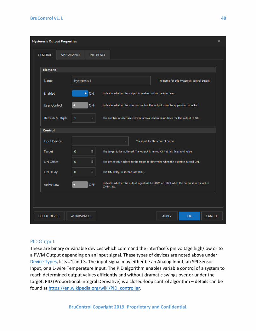
BruControl v1.1 48
BruControl Copyright 2019. Proprietary and Confidential.
PID Output These are binary or variable devices which command the interface’s pin voltage high/low or to a PWM Output depending on an input signal. These types of devices are noted above under Device Types, lists #1 and 3. The input signal may either be an Analog Input, an SPI Sensor Input, or a 1-wire Temperature Input. The PID algorithm enables variable control of a system to reach determined output values efficiently and without dramatic swings over or under the target. PID (Proportional Integral Derivative) is a closed-loop control algorithm – details can be found at https://en.wikipedia.org/wiki/PID_controller.
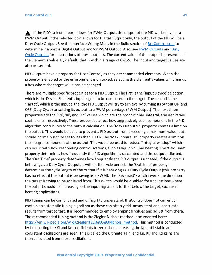
BruControl v1.1 49
BruControl Copyright 2019. Proprietary and Confidential.
If the PID’s selected port allows for PWM Output, the output of the PID will behave as a PWM Output. If the selected port allows for Digital Output only, the output of the PID will be a Duty Cycle Output. See the Interface Wiring Maps in the Build section of BruControl.com to determine if a port is Digital Output and/or PWM Output. Also, see PWM Outputs and Duty Cycle Outputs for descriptions of these outputs. The current value of the output is presented as the Element’s value. By default, that is within a range of 0-255. The input and target values are also presented.
PID Outputs have a property for User Control, as they are commanded elements. When the property is enabled or the environment is unlocked, selecting the Element’s values will bring up a box where the target value can be changed.
There are multiple specific properties for a PID Output. The first is the ‘Input Device’ selection, which is the Device Element’s input signal to be compared to the target. The second is the ‘Target’, which is the input signal the PID Output will try to achieve by turning its output ON and OFF (Duty Cycle) or setting its output to a PWM percentage (PWM Output). The next three properties are the ‘Kp’, ‘Ki’, and ‘Kd’ values which are the proportional, integral, and derivative coefficients, respectively. These properties affect how aggressively each component in the PID algorithm contributes to the output calculation. The ‘Max Output %’ property creates a limit on the output. This would be used to prevent a PID output from exceeding a maximum value, but should normally not be set to less than 100%. The ‘Max Integral %’ property creates a limit on the integral component of the output. This would be used to reduce “integral windup” which can occur with slow responding control systems, such as liquid volume heating. The ‘Calc Time’ property determines how frequently the PID algorithm is calculated and the output adjusted. The ‘Out Time’ property determines how frequently the PID output is updated. If the output is behaving as a Duty Cycle Output, it will set the cycle period. The ‘Out Time’ property determines the cycle length of the output if it is behaving as a Duty Cycle Output (this property has no effect if the output is behaving as a PWM). The ‘Reversed’ switch inverts the direction the target is trying to be achieved from. This switch would be disabled for applications where the output should be increasing as the input signal falls further below the target, such as in heating applications.
PID Tuning can be complicated and difficult to understand. BruControl does not currently contain an automatic tuning algorithm as these can often yield inconsistent and inaccurate results from test to test. It is recommended to employ empirical values and adjust from there. The recommended tuning method is the Ziegler-Nichols method, documented here: https://en.wikipedia.org/wiki/Ziegler%E2%80%93Nichols_method. This method is conducted by first setting the Ki and Kd coefficients to zero, then increasing the Kp until stable and consistent oscillations are seen. This is called the ultimate gain, and Kp, Ki, and Kd gains are then calculated from those oscillations.
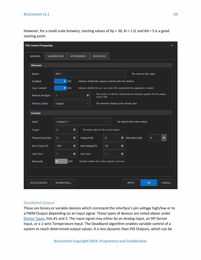
BruControl v1.1 50
BruControl Copyright 2019. Proprietary and Confidential.
However, for a small scale brewery, starting values of Kp = 30, Ki = 1.0, and Kd = 5 is a good starting point.
Deadband Output These are binary or variable devices which command the interface’s pin voltage high/low or to a PWM Output depending on an input signal. These types of devices are noted above under Device Types, lists #1 and 3. The input signal may either be an Analog Input, an SPI Sensor Input, or a 1-wire Temperature Input. The Deadband algorithm enables variable control of a system to reach determined output values. It is less dynamic than PID Outputs, which can be

BruControl v1.1 51
BruControl Copyright 2019. Proprietary and Confidential.
better suited to control systems that benefit from a slower response, such as automatic valve control. Deadband Outputs also use an initial output to set the system in an appropriate output region.
If the Deadband’s selected port allows for PWM Output, the output of the Deadband will behave as a PWM Output. If the selected port allows for Digital Output only, the output of the Deadband will be a Duty Cycle Output. See the Interface Wiring Maps in the Build section of BruControl.com to determine if a port is Digital Output and/or PWM Output. Also, see PWM Outputs and Duty Cycle Outputs for descriptions of these outputs. The current value of the output is presented as the Element’s value. By default, that is within a range of 0-255. The input and target values are also presented.
Deadband Outputs have a property for User Control, as they are commanded elements. When the property is enabled or the environment is unlocked, selecting the Element’s values will bring up a box where the target value can be changed.
There are multiple specific properties for a Deadband Output. The first is the ‘Input Device’ selection, which is the Device Element’s input signal to be compared to the target. The second is the ‘Target’, which is the input signal the Deadband Output will try to approximate by turning its output ON and OFF (Duty Cycle) or setting its output to a PWM percentage (PWM Output).
The ‘Deadband Offset’ property determines the range of values, centered about the Target, for which the Deadband Device Element’s output will remain unchanged. Its value is associated with the amount above or below the target. Therefore, the total Deadband range is twice this amount. The ‘Inner Band Offset’ property determines the range of values, centered about the Target and excluding the Deadband, for which the Deadband Device Element’s output will change, either positively or negatively, by the Inner Band Drive. Its value is associated with the amount above or below the target. Therefore, the total Inner Band range is twice this amount.
The ‘Initial Output’ property determines the Deadband Device Element’s output value when the device is first enabled.The ‘Inner Band Drive’ and ‘Outer Band Drive’ properties determine the output change that occurs with each calculation cycle in the inner band and outer band, respectively. The ‘Calc Time’ property determines how frequently the Deadband algorithm is calculated and the output adjusted. The ‘Out Time’ property determines the cycle length of the output if it is behaving as a Duty Cycle Output (this property has no effect if the output is behaving as a PWM). The ‘Reversed’ switch inverts the direction the target is trying to be achieved from. This switch would be disabled for applications where the output should be increasing as the input signal falls further below the target, such as in heating applications.

BruControl v1.1 52
BruControl Copyright 2019. Proprietary and Confidential.
Simply stated, when the input is within the deadband, the output remains unaffected. If the input falls inside the deadband threshold, but inside the inner band, it will increase (if input is below the target) or decrease (if input is above the target) with each calculation cycle by the inner band drive amount. If the input is outside the inner band threshold, it will increase (if input is below the target) or decrease (if input is above the target) with each calculation cycle by the outer band drive amount. See the graphic below for guidance.
Deadbands should not be used when there is a significant time lag in the control system’s response and/or the input is not near the target, as it will likely aggressively overshoot during approach, since the additive nature of this algorithm approximates a PID with an unlimited integrator. PID Outputs should be used in those applications.
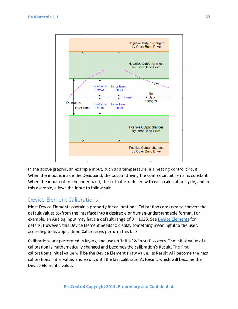
BruControl v1.1 53
BruControl Copyright 2019. Proprietary and Confidential.
In the above graphic, an example input, such as a temperature in a heating control circuit. When the input is inside the Deadband, the output driving the control circuit remains constant. When the input enters the inner band, the output is reduced with each calculation cycle, and in this example, allows the input to follow suit.
Device Element Calibrations Most Device Elements contain a property for calibrations. Calibrations are used to convert the default values to/from the interface into a desirable or human-understandable format. For example, an Analog Input may have a default range of 0 – 1023. See Device Elements for details. However, this Device Element needs to display something meaningful to the user, according to its application. Calibrations perform this task.
Calibrations are performed in layers, and use an ‘initial’ & ‘result’ system. The Initial value of a calibration is mathematically changed and becomes the calibration’s Result. The first calibration’s Initial value will be the Device Element’s raw value. Its Result will become the next calibrations Initial value, and so on, until the last calibration’s Result, which will become the Device Element’s value.

BruControl v1.1 54
BruControl Copyright 2019. Proprietary and Confidential.
For example, in the example below, this Analog Input is measuring 548 as its raw value, which is the first calibration’s Initial value. A thermistor calculation is applied, yielding Result of 301.4 (which is the temperature in Kelvin). That value is then passed to the next calibration which is an offset calculation, yielding a Result of 28.2 (this offset calculation converts Kelvin to Celsius). That value is then passed to a temperature conversion calculation, resulting in a final Device value of 82.8.
To add a calibration layer, select the ‘CALIBRATION’ tab of a Device Element’s properties. Select the Property of that Device Element, which will typically be its value. Select the ‘ADD…’ button, select the type of calibration to be applied, then enter the appropriate properties and enable it via the ‘Enabled’ switch. To edit a specific calibration, select it in the list, then select ‘EDIT…’. Calibrations can be selectively disabled via ‘EDIT…’ as well. To move a specific calibration up or down in the list, select it in the list, then select the ‘MOVE UP’ or ‘MOVE DOWN’ buttons. Note

BruControl v1.1 55
BruControl Copyright 2019. Proprietary and Confidential.
doing this will affect the order of the calculations as well as the order of the list. To delete a specific calibration, select it in the list, then select the ‘REMOVE’ button.
Linear Offset Linear Offset calibrations add a value to the input to create the output value. This calibration can be used to increase or decrease a value by any amount desired, affecting a linear system’s “intersection”. The ‘Offset’ amount can be positive or negative, as in this example, where the temperature in Kelvin is converted to Celsius by adding -273.15 (equivalent to subtracting 273.15).
Linear Multiplier/Divider Linear Multiplier or Divider calibrations multiply or divide the input by a value to create the output value. This calibration can be used to increase or decrease a value by any amount desired, affecting a linear system’s “slope”. The ‘Multiplier’ amount can be positive or negative, as in this example, where the temperature in Celsius is partially converted to Fahrenheit by multiplying the input by 1.8 (note there is a native conversion, below). Divider values are the divisor in the division operation.

BruControl v1.1 56
BruControl Copyright 2019. Proprietary and Confidential.
Floor Floor calibrations limit the output to be no lower than this property. Caution should be applied when using these calibrations, as they affect dependent Device Elements (e.g. Hysteresis Output) in unexpected ways.
Ceiling Ceiling calibrations limit the output to be no higher than this property. Caution should be applied when using these calibrations, as they affect dependent Device Elements (e.g. Hysteresis Output) in unexpected ways.
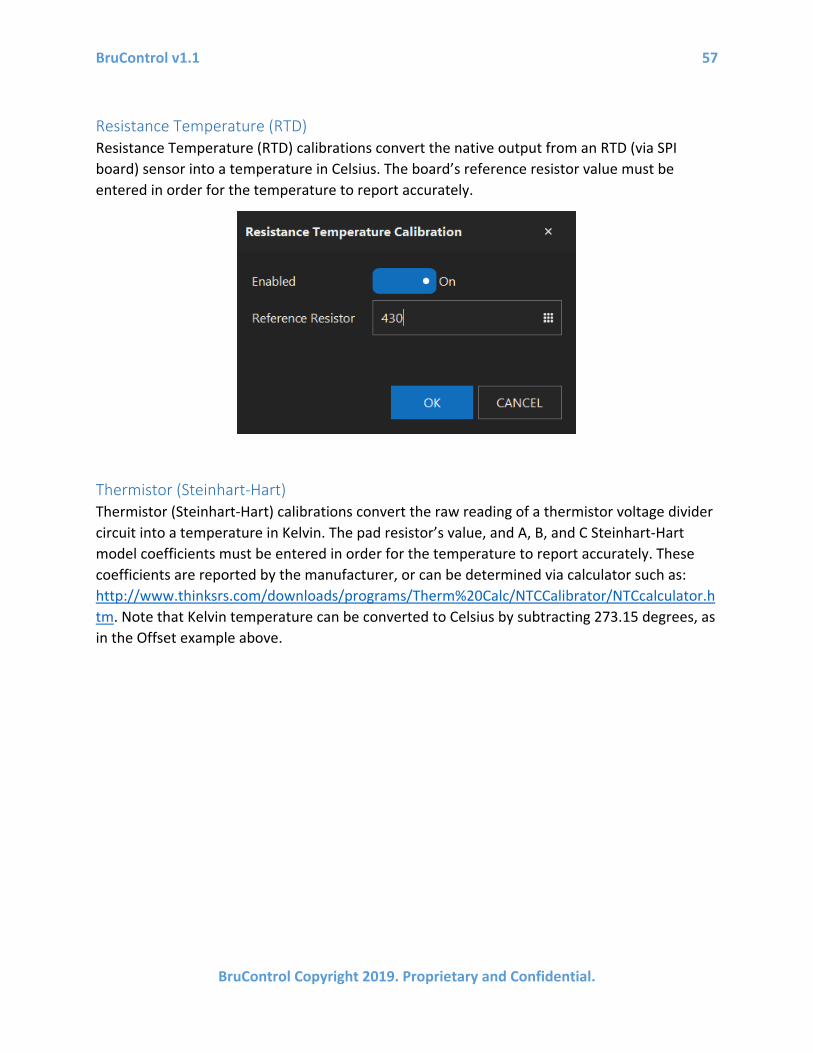
BruControl v1.1 57
BruControl Copyright 2019. Proprietary and Confidential.
Resistance Temperature (RTD) Resistance Temperature (RTD) calibrations convert the native output from an RTD (via SPI board) sensor into a temperature in Celsius. The board’s reference resistor value must be entered in order for the temperature to report accurately.
Thermistor (Steinhart-Hart) Thermistor (Steinhart-Hart) calibrations convert the raw reading of a thermistor voltage divider circuit into a temperature in Kelvin. The pad resistor’s value, and A, B, and C Steinhart-Hart model coefficients must be entered in order for the temperature to report accurately. These coefficients are reported by the manufacturer, or can be determined via calculator such as: http://www.thinksrs.com/downloads/programs/Therm%20Calc/NTCCalibrator/NTCcalculator.htm. Note that Kelvin temperature can be converted to Celsius by subtracting 273.15 degrees, as in the Offset example above.

BruControl v1.1 58
BruControl Copyright 2019. Proprietary and Confidential.
Celsius to Fahrenheit Celsius to Fahrenheit calibrations convert the temperature in Celsius into Fahrenheit.
Fahrenheit to Celsius Celsius to Fahrenheit calibrations convert the temperature in Fahrenheit into Celsius.
Kelvin to Fahrenheit Kelvin to Fahrenheit calibrations convert the temperature in Kelvin into Farenheit.
Fahrenheit to Kelvin Fahrenheit to Kelvin calibrations convert the temperature in Farenheit into Kelvin.
Lookup Table Lookup Table calibrations are very powerful as they can convert nearly any input value into any output value. These calibrations allow for the conversion of non-linear, parametric, or polynomial value pairs. These can be used to correct non-linear errors in an interface’s ADC (analog-digital converter) or approximate any desired calibration curve.
The calibration Initial value is checked against the X values in the lookup table. Where matched, the corresponding Y value is applied as the calibration’s Result. When the Initial value falls between two X values, the calibration Result is the value interpolated between the corresponding Y values. This interpolation is linear, so if higher accuracy is required over a

BruControl v1.1 59
BruControl Copyright 2019. Proprietary and Confidential.
broad range of X and Y values, the number of value pairs in the lookup table should be increased. Decimals may be used in X values as needed.
Note: X values will automatically be sorted from the lowest value to the highest value in order. However, the X values MUST exceed the range of possible minimum and maximum Initial values that will enter the lookup table to prevent calculation errors. It is recommended the differences between each X value in the table be consistent across the whole table.
X and Y data value pairs can be manually added using the ‘ADD’ button. X values will automatically be added in increasing value order. To edit or remove a value pair, select the pair line and select ‘EDIT…’ or ‘REMOVE’ respectively.
Value pair tables can be created using an external tool such as Excel, then the table imported into the lookup table using the ‘IMPORT…’ button. Tables must be in *.CSV (Comma Delimited) format. In addition, a table can be exported for backup purposes using the ‘EXPORT…’ button.
Text Format The Calibration properties box also allows for adjustment of the final value’s text format. To change the number of decimal places presented as the Device Element’s value, select the desired number in ‘Decimal Places’. To add a prefix or suffix to the Device Element’s value,
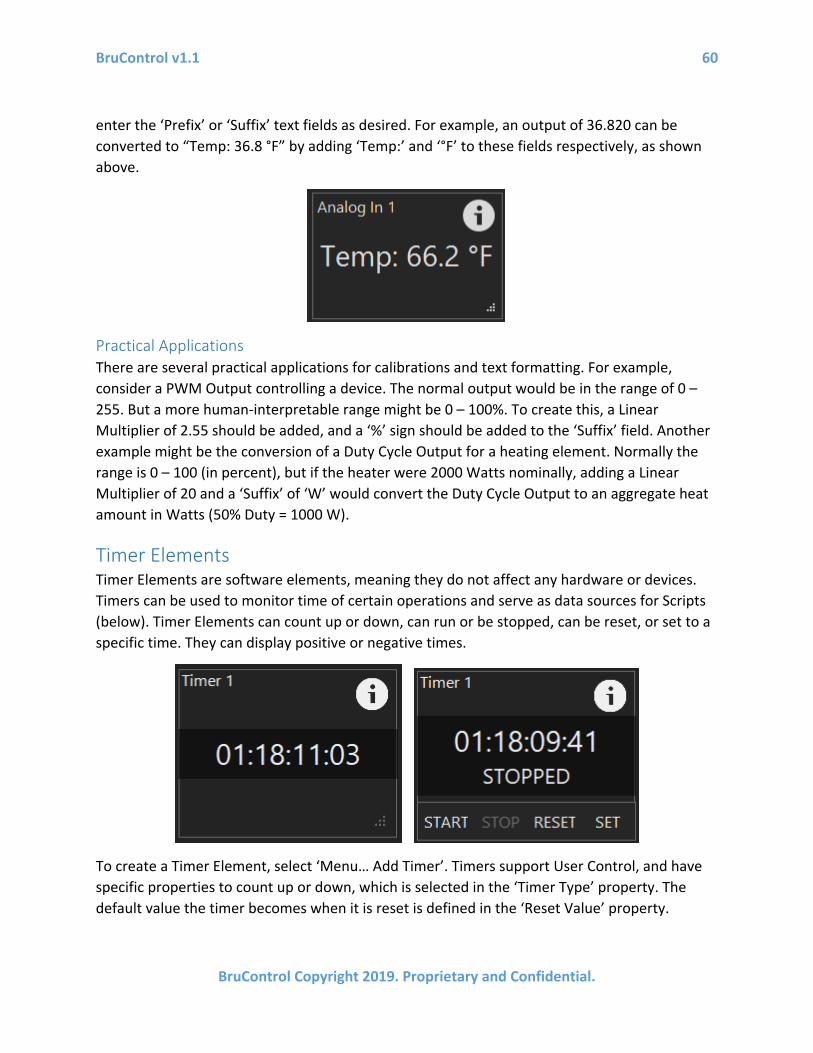
BruControl v1.1 60
BruControl Copyright 2019. Proprietary and Confidential.
enter the ‘Prefix’ or ‘Suffix’ text fields as desired. For example, an output of 36.820 can be converted to “Temp: 36.8 °F” by adding ‘Temp:’ and ‘°F’ to these fields respectively, as shown above.
Practical Applications There are several practical applications for calibrations and text formatting. For example, consider a PWM Output controlling a device. The normal output would be in the range of 0 – 255. But a more human-interpretable range might be 0 – 100%. To create this, a Linear Multiplier of 2.55 should be added, and a ‘%’ sign should be added to the ‘Suffix’ field. Another example might be the conversion of a Duty Cycle Output for a heating element. Normally the range is 0 – 100 (in percent), but if the heater were 2000 Watts nominally, adding a Linear Multiplier of 20 and a ‘Suffix’ of ‘W’ would convert the Duty Cycle Output to an aggregate heat amount in Watts (50% Duty = 1000 W).
Timer Elements Timer Elements are software elements, meaning they do not affect any hardware or devices. Timers can be used to monitor time of certain operations and serve as data sources for Scripts (below). Timer Elements can count up or down, can run or be stopped, can be reset, or set to a specific time. They can display positive or negative times.
To create a Timer Element, select ‘Menu… Add Timer’. Timers support User Control, and have specific properties to count up or down, which is selected in the ‘Timer Type’ property. The default value the timer becomes when it is reset is defined in the ‘Reset Value’ property.
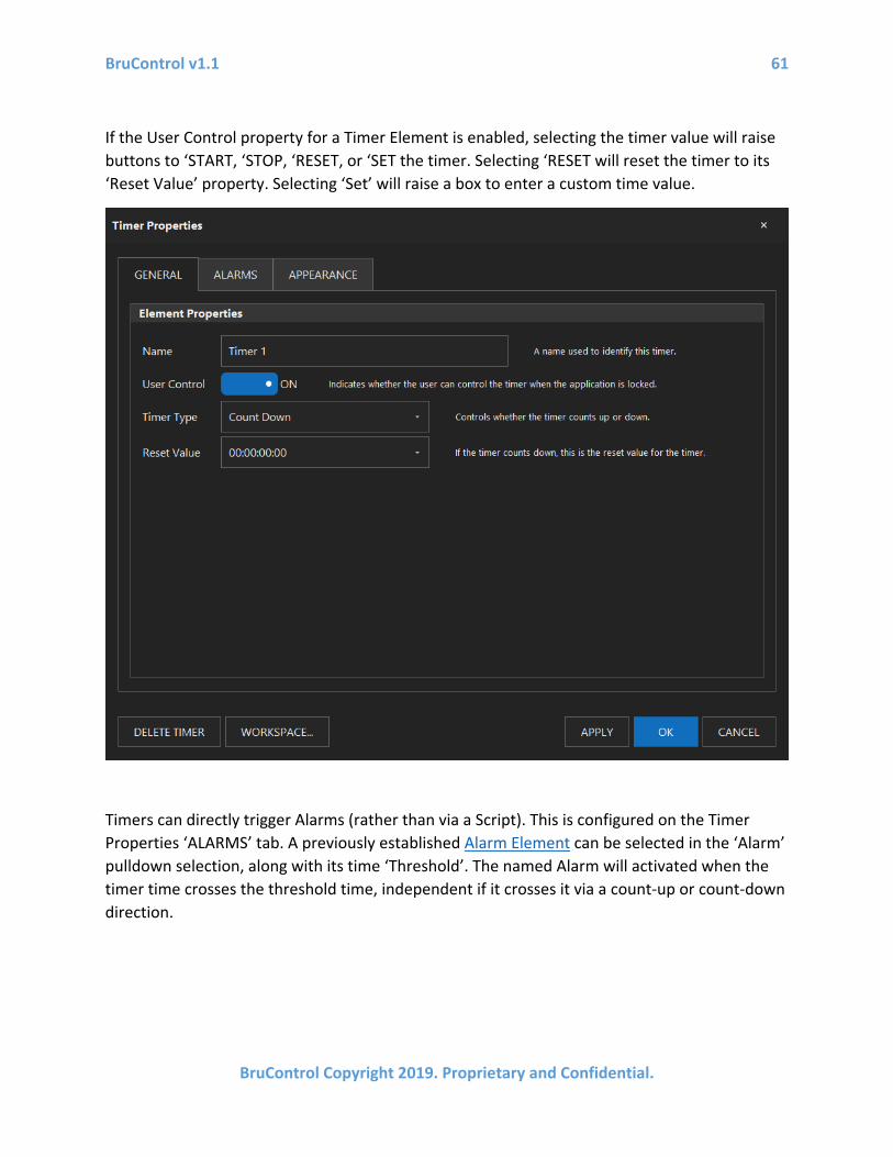
BruControl v1.1 61
BruControl Copyright 2019. Proprietary and Confidential.
If the User Control property for a Timer Element is enabled, selecting the timer value will raise buttons to ‘START, ‘STOP, ‘RESET, or ‘SET the timer. Selecting ‘RESET will reset the timer to its ‘Reset Value’ property. Selecting ‘Set’ will raise a box to enter a custom time value.
Timers can directly trigger Alarms (rather than via a Script). This is configured on the Timer Properties ‘ALARMS’ tab. A previously established Alarm Element can be selected in the ‘Alarm’ pulldown selection, along with its time ‘Threshold’. The named Alarm will activated when the timer time crosses the threshold time, independent if it crosses it via a count-up or count-down direction.

BruControl v1.1 62
BruControl Copyright 2019. Proprietary and Confidential.
Alarm Elements Alarm Elements are software elements, meaning they do not necessarily affect any hardware or devices. Alarms can be used to notify a user of a certain condition. Alarms provide notification via their displayed state (ON or OFF), via a configurable alert sound, via email, and/or via the activation of a definable Digital Output. If that Digital Output is tied to a physical alarm, the alarms will be activated and deactivated together.
To create an Alarm Element, select ‘Menu… Add Alarm’. Alarms support User Control, therefore selecting the Alarm Element’s state will toggle its activation. This allows for a user to deactivate the alarm even when the Environment is locked.
Alarm Elements have several specific properties. To send an email when an alarm is activated, enable the ‘Email Notification’ switch. Email notifications are configured in the Application Settings above. BruControl will play an alert sound when an alarm is activated. To change from the ‘Default’ sound, select the ‘Custom’ option and select a wave format (.wav) file from the computer’s library using the ‘BROWSE’ button. The default sound will automatically loop, but

BruControl v1.1 63
BruControl Copyright 2019. Proprietary and Confidential.
for custom sounds, looping is an option via the ‘Loop’ switch. To turn on a Digital Output along with the alarm activation, select an appropriate Device Element in the ‘Digital Output’ field. The selected Digital Output can be on any interface, but the Device Element must already be enabled in order for the alarm to change the Device Element’s state.
Graph Elements Graph Elements are software elements, meaning they do not affect any hardware or devices. Graphs are used to record and display values of different elements’ properties over time. These properties may be values, states, etc. Graph Elements plot time as the horizontal axis and the selected property as the vertical axis. The axis bounds are automatically sized to accommodate the data to be plotted.

BruControl v1.1 64
BruControl Copyright 2019. Proprietary and Confidential.
To create a Graph Element, select ‘Menu… Add Graph’. Graphs do not support User Control as they are read-only elements.
Graphs Elements have several specific properties. ‘Refresh Interval’ determines how often the graph is refreshed (redrawn), and is selectable from 1 to 60 seconds. ‘Time Span’ defines the maximum amount of time to plot going backwards from the last plot, and is selectable in days, hours, minutes, and seconds. Note that data will be recorded and maintained for up to 30 days.
Up to two data sources can be simultaneously plotted. The ‘Primary Value’ will be plotted on using the left vertical axis, and the ‘Secondary Value’ will be plotted using the right vertical axis. To set automatic axis scaling, set the ‘Axis Scale’ switch to ‘Automatic’. To manually scale, set this switch to ‘Manual’.
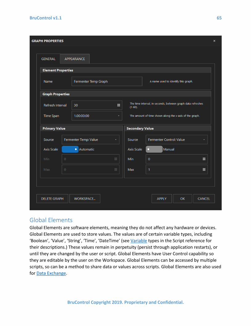
BruControl v1.1 65
BruControl Copyright 2019. Proprietary and Confidential.
Global Elements Global Elements are software elements, meaning they do not affect any hardware or devices. Global Elements are used to store values. The values are of certain variable types, including ‘Boolean’, ‘Value’, ‘String’, ‘Time’, ‘DateTime’ (see Variable types in the Script reference for their descriptions.) These values remain in perpetuity (persist through application restarts), or until they are changed by the user or script. Global Elements have User Control capability so they are editable by the user on the Workspace. Global Elements can be accessed by multiple scripts, so can be a method to share data or values across scripts. Global Elements are also used for Data Exchange.

BruControl v1.1 66
BruControl Copyright 2019. Proprietary and Confidential.
Inspector Elements Inspector Elements (previously called Variable Elements in v1.0) are software elements, meaning they do not affect any hardware or devices. Inspector Elements are used to display variables used in Scripts. See Scripts for details. Variables which can be displayed may be numeric values, time values, boolean states (true/false), or text strings.
To create an Inspector Element, select ‘Menu… Add Inspector.

BruControl v1.1 67
BruControl Copyright 2019. Proprietary and Confidential.
Inspector Elements support User Control, which will permit their value to be changed if enabled.
Inspector Elements have several specific properties. ‘Script’ defined which Script the variable is stored in. ‘Variable Name’ is the name of the variable in the Script to be displayed.
Button and Switch Elements Button Elements and Switch Elements are software elements, meaning they do not necessarily affect any hardware or devices. These allow for the user to interact with the control system through Scripts. See Scripts for details.

BruControl v1.1 68
BruControl Copyright 2019. Proprietary and Confidential.
To create a Button Element, select ‘Menu… Add Button’. To create a Switch Element, select ‘Menu… Add Switch. Both Button Elements and Switch Elements support User Control, therefore buttons and Switches may only function when the Environment is unlocked or User Control is enabled for that button.
Neither Button Elements nor Switch Elements have editable properties.
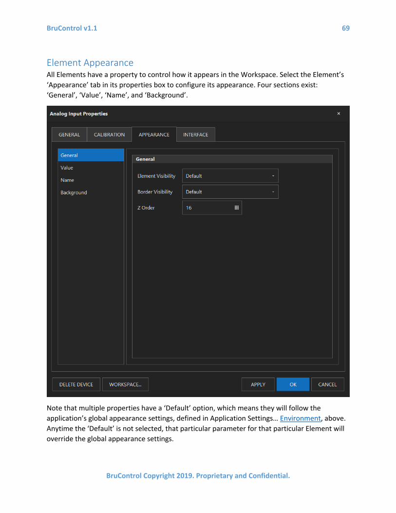
BruControl v1.1 69
BruControl Copyright 2019. Proprietary and Confidential.
Element Appearance All Elements have a property to control how it appears in the Workspace. Select the Element’s ‘Appearance’ tab in its properties box to configure its appearance. Four sections exist: ‘General’, ‘Value’, ‘Name’, and ‘Background’.
Note that multiple properties have a ‘Default’ option, which means they will follow the application’s global appearance settings, defined in Application Settings… Environment, above. Anytime the ‘Default’ is not selected, that particular parameter for that particular Element will override the global appearance settings.

BruControl v1.1 70
BruControl Copyright 2019. Proprietary and Confidential.
The ‘General’ section is used to set the Element’s appearance. ‘Element Visibility’ defines the whole Element’s visibility, with options for ‘Default’, ‘Visible’, ‘Hidden’, and ‘Hidden Locked’. ‘Visible’ means the Element will always be visible. ‘Hidden’ means the Element will always be hidden unless the Visibility icon is toggled on. ‘Hidden Locked’ means the Element will be hidden when the Environment is locked, unless the Visibility icon is toggled on.
‘Border Visibility’ defines the Element’s border’s visibility, with options for ‘Default’, ‘Visible’, ‘Hidden’, and ‘Hidden Locked’. ‘Visible’ means the Element will always be visible. ‘Hidden’ means the Element will always be hidden. ‘Hidden Locked’ means the Element will be hidden when the Environment is locked.
‘Z Order’ determines which Element will be given display priority when Elements overlap. Lower Z Order numbers indicate higher priority. To change an Element’s priority, select the up/down arrows. Doing so will adjust the Element’s position in the list, thereby re-ordering the entire list. When new Elements are created, they are assigned the highest priority (Z Order = 1) and the remainder of the list is shifted to a lower priority (Z Order number increased by one).

BruControl v1.1 71
BruControl Copyright 2019. Proprietary and Confidential.
The ‘Value’ section is used to set the appearance of the value inside the Element. ‘Display Type’ sets how an Element’s value is represented. ‘Text’ is the default, and the data is presented in clear text. ‘Digital Gauge’ presents the data in a classic LED/LCD multi-segment display format. ‘Circular Gauge’ presents the data in a needle & dial format. ‘Linear Guage’ presents the data in a vertical or horizontal straight gauge format. ‘LED’ presents ON/OFF data using a colored LED type indicator. Each of these settings have customizable sub-settings which will change to configure the display type.
For the Text Display Type, the sub-settings include the ‘Font’ (customizable system font), the ‘Enlargement’ (increased font size up to 30 points), the ‘Alignment’ (Top, Middle, Bottom and
BruControl v1.1 72
BruControl Copyright 2019. Proprietary and Confidential.
Left, Center, Right), the ‘Back Color’ (color behind the text), the ‘Fore Color’ (color of the text), ‘OFF Text’, and ‘ON Text’. These last two options will replace binary digital ON/OFF values with customizable text. For example, for a Hysteresis Device, when it is ON, the Element could report “POWERED” instead. For Digital Gauge, Circular Gauge, and Linear Gauge Display Types, a ‘Style’ can be selected as a pre-defined gauge style. The other sub-settings should be self-explanatory for these Display Types. For the ‘LED Indicator’ Display Type, an LED will replace binary digital ON/OFF values for devices which use those. The ON and OFF colors are selectable.
The ‘Name’ section is used to set the appearance of the Element name. Sub-settings ‘Font’, ‘Visibility’, ‘Alignment’, ‘Back Color’, and ‘Fore Color’ are the same as the Value, but apply to the Element name.
The ‘Background Image’ section is used to set an image within the Element as its backdrop. The image will be stretched to accommodate the width and height of the Element. Up to three images may be queued, with the active one selected via the ‘Selected Image’ pulldown. To define an image, use ‘BROWSE…’, and select one in JPEG, Portable Network Graphics, or Bitmap (.jpg, .jpeg, .png, or .bmp) format from the computer’s library. Selecting the circular X icon will remove the image and revert the element to its default state.
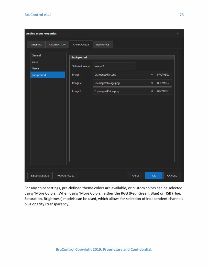
BruControl v1.1 73
BruControl Copyright 2019. Proprietary and Confidential.
For any color settings, pre-defined theme colors are available, or custom colors can be selected using ‘More Colors’. When using ‘More Colors’, either the RGB (Red, Green, Blue) or HSB (Hue, Saturation, Brightness) models can be used, which allows for selection of independent channels plus opacity (transparency).
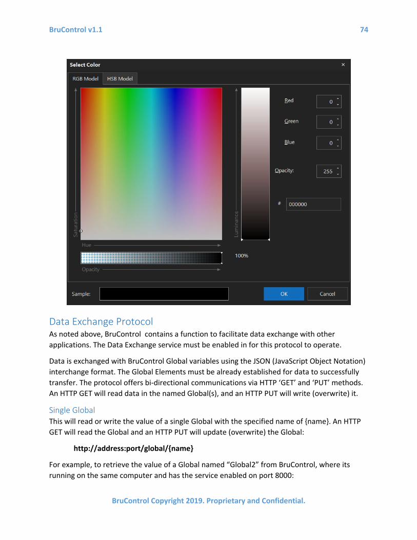
BruControl v1.1 74
BruControl Copyright 2019. Proprietary and Confidential.
Data Exchange Protocol As noted above, BruControl contains a function to facilitate data exchange with other applications. The Data Exchange service must be enabled in for this protocol to operate.
Data is exchanged with BruControl Global variables using the JSON (JavaScript Object Notation) interchange format. The Global Elements must be already established for data to successfully transfer. The protocol offers bi-directional communications via HTTP ‘GET’ and ‘PUT’ methods. An HTTP GET will read data in the named Global(s), and an HTTP PUT will write (overwrite) it.
Single Global This will read or write the value of a single Global with the specified name of {name}. An HTTP GET will read the Global and an HTTP PUT will update (overwrite) the Global:
http://address:port/global/{name}
For example, to retrieve the value of a Global named “Global2” from BruControl, where its running on the same computer and has the service enabled on port 8000:
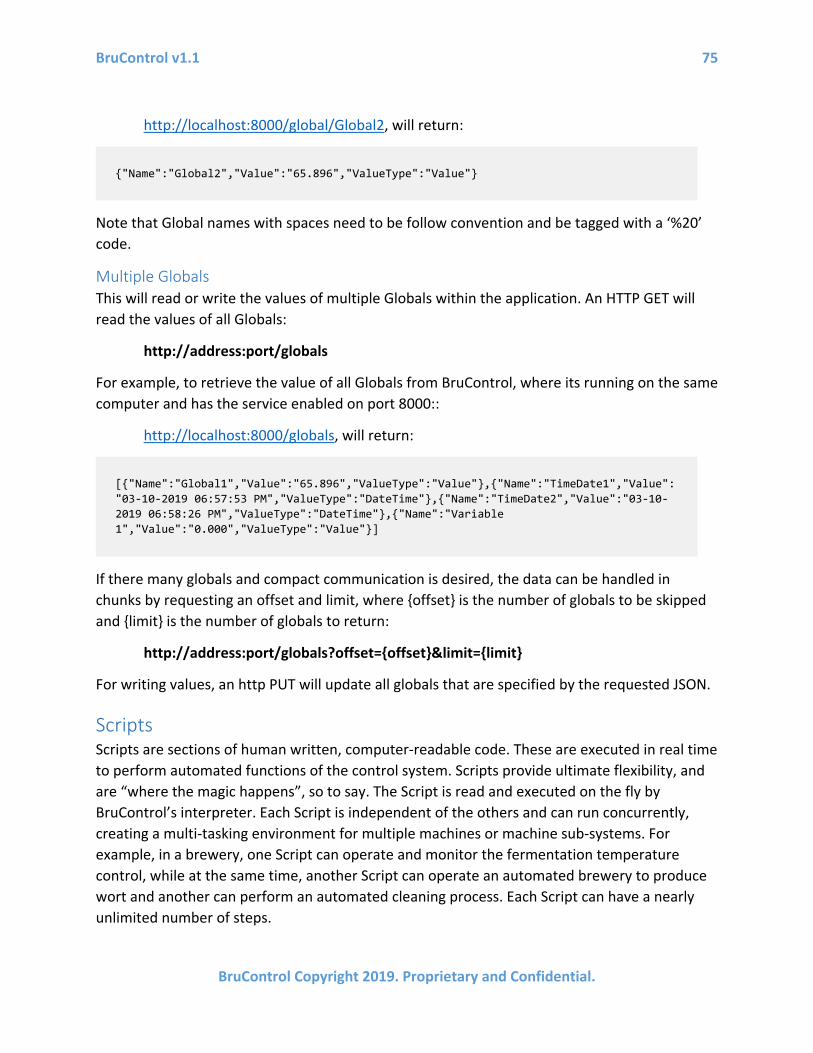
BruControl v1.1 75
BruControl Copyright 2019. Proprietary and Confidential.
http://localhost:8000/global/Global2, will return:
Note that Global names with spaces need to be follow convention and be tagged with a ‘%20’ code.
Multiple Globals This will read or write the values of multiple Globals within the application. An HTTP GET will read the values of all Globals:
http://address:port/globals
For example, to retrieve the value of all Globals from BruControl, where its running on the same computer and has the service enabled on port 8000::
http://localhost:8000/globals, will return:
If there many globals and compact communication is desired, the data can be handled in chunks by requesting an offset and limit, where {offset} is the number of globals to be skipped and {limit} is the number of globals to return:
http://address:port/globals?offset={offset}&limit={limit}
For writing values, an http PUT will update all globals that are specified by the requested JSON.
Scripts Scripts are sections of human written, computer-readable code. These are executed in real time to perform automated functions of the control system. Scripts provide ultimate flexibility, and are “where the magic happens”, so to say. The Script is read and executed on the fly by BruControl’s interpreter. Each Script is independent of the others and can run concurrently, creating a multi-tasking environment for multiple machines or machine sub-systems. For example, in a brewery, one Script can operate and monitor the fermentation temperature control, while at the same time, another Script can operate an automated brewery to produce wort and another can perform an automated cleaning process. Each Script can have a nearly unlimited number of steps.
{"Name":"Global2","Value":"65.896","ValueType":"Value"}
[{"Name":"Global1","Value":"65.896","ValueType":"Value"},{"Name":"TimeDate1","Value":"03-10-2019 06:57:53 PM","ValueType":"DateTime"},{"Name":"TimeDate2","Value":"03-10-2019 06:58:26 PM","ValueType":"DateTime"},{"Name":"Variable 1","Value":"0.000","ValueType":"Value"}]
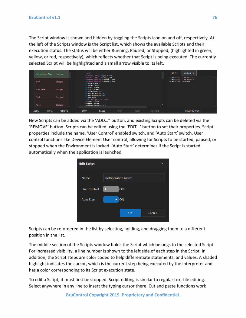
BruControl v1.1 76
BruControl Copyright 2019. Proprietary and Confidential.
The Script window is shown and hidden by toggling the Scripts icon on and off, respectively. At the left of the Scripts window is the Script list, which shows the available Scripts and their execution status. The status will be either Running, Paused, or Stopped, (highlighted in green, yellow, or red, respectively), which reflects whether that Script is being executed. The currently selected Script will be highlighted and a small arrow visible to its left.
New Scripts can be added via the ‘ADD…” button, and existing Scripts can be deleted via the ‘REMOVE’ button. Scripts can be edited using the ‘EDIT…’ button to set their properties. Script properties include the name, ‘User Control’ enabled switch, and ‘Auto Start’ switch. User control functions like Device Element User control, allowing for Scripts to be started, paused, or stopped when the Environment is locked. ‘Auto Start’ determines if the Script is started automatically when the application is launched.
Scripts can be re-ordered in the list by selecting, holding, and dragging them to a different position in the list.
The middle section of the Scripts window holds the Script which belongs to the selected Script. For increased visibility, a line number is shown to the left side of each step in the Script. In addition, the Script steps are color coded to help differentiate statements, and values. A shaded highlight indicates the cursor, which is the current step being executed by the interpreter and has a color corresponding to its Script execution state.
To edit a Script, it must first be stopped. Script editing is similar to regular text file editing. Select anywhere in any line to insert the typing cursor there. Cut and paste functions work

BruControl v1.1 77
BruControl Copyright 2019. Proprietary and Confidential.
normally. See BruControl Script Language for the available commands and statements and their respective syntaxes.
Below the Script window are buttons to control the Script’s execution. ‘STOP’ stops a running or paused Script and ‘PAUSE’ pauses a running Script. When a Script is stopped, ‘RUN’ loads and starts it in one step, while ‘LOAD’ prepares the script for execution in memory. When a Script is paused, ‘RESUME’ continues automatic execution, ‘STEP’ executes the next line below the cursor then pauses again, ‘RESET’ tells the interpreter to discard any script variables in memory and move the cursor to the beginning of the script, and ‘SET HERE’ moves the cursor to the section heading of the selected step. See BruControl Script Language for Sections details.
To the right of the Scripts window is the ‘OUTPUT/VARIABLES’ section. The ‘OUTPUT’ tab shows the history of a Script’s execution and errors with timestamps. This is used to debug Script syntax. The ‘CLEAR OUTPUT’ button will erase this history. The ‘VARIABLES’ tab shows the variables currently defined in the Script and their respective values. This is used for monitoring variable values.

BruControl v1.1 78
BruControl Copyright 2019. Proprietary and Confidential.
BruControl Script Language Introduction This section provides information about the scripting language used in BruControl. Scripts are sections of specific syntax text, and are editable like a simple text editor. Each Script is executed in sequential line order by the BruControl interpreter.
It is recommended to edit Scripts using a keyboard based computer for ease or writing, speed, and manipulation. The text editor supports basic editing control commands such as CTRL+C for ‘copy’, CTRL+X for ‘cut’, CTRL+V for ‘paste’, CTRL+Z for ‘undo’. In addition, CTRL+F or CTRL+H will raise Find or Find & Replace dialogs, respectively.
Name Convention and Syntax Elements must not have duplicate names, otherwise the interpreter may confuse one
element with another. Elements may be named with text, spaces, numbers, etc. to differentiate. Since Device Elements can address the same device, it is recommended that the type of control be included in the name for clarity, for example “Boil Kettle PID” rather than “Boil Kettle”.
Unlike structured or compiled languages, spaces are not ignored by the interpreter. Therefore, the syntax of the statements often require a single space to separate their properties, as demonstrated in the examples below.
Capitalization is followed with respect to Element names only. Statements, properties, and variables do not require or follow capitalization. For example, an Element name of “DigitalOut” is not the same as “digitalout”, but statements ‘stop’, ‘Stop’, or ‘STOP’ are all evaluated equally by the interpreter.
Sections Code is grouped into named sections. A section heading is declared using square braces. A ‘goto’ statement is used to jump execution to a specific section.
Syntax:
[mysection], where mysection is the name of the section.
goto “mysection”, where mysection is the name of the section.
Example:
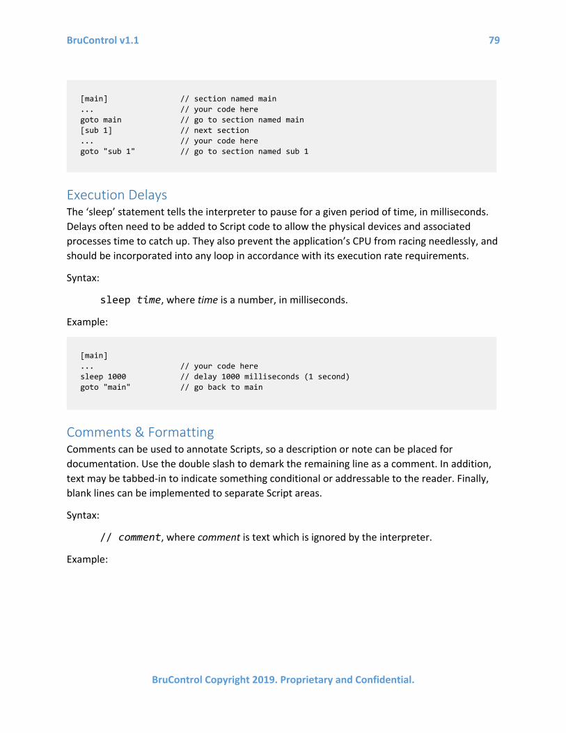
BruControl v1.1 79
BruControl Copyright 2019. Proprietary and Confidential.
Execution Delays The ‘sleep’ statement tells the interpreter to pause for a given period of time, in milliseconds. Delays often need to be added to Script code to allow the physical devices and associated processes time to catch up. They also prevent the application’s CPU from racing needlessly, and should be incorporated into any loop in accordance with its execution rate requirements.
Syntax:
sleep time, where time is a number, in milliseconds.
Example:
Comments & Formatting Comments can be used to annotate Scripts, so a description or note can be placed for documentation. Use the double slash to demark the remaining line as a comment. In addition, text may be tabbed-in to indicate something conditional or addressable to the reader. Finally, blank lines can be implemented to separate Script areas.
Syntax:
// comment, where comment is text which is ignored by the interpreter.
Example:
[main] // section named main ... // your code here goto main // go to section named main [sub 1] // next section ... // your code here goto "sub 1" // go to section named sub 1
[main] ... // your code here sleep 1000 // delay 1000 milliseconds (1 second) goto "main" // go back to main

BruControl v1.1 80
BruControl Copyright 2019. Proprietary and Confidential.
Variables The scripting interpreter provides support for the following types of variables.
• value – A numeric value, which can be an integer or decimal • time – A time value, which represents a span of time, formatted as hh:mm:ss • datetime – A date and time value, which represents a point in time • bool – A boolean value, which can be either true or false • string – A character string, which can be any text, marked in quotes
Before a variable can be used, it must be declared using the ‘new’ statement. Note that assignments require an equals sign, separated by spaces on each side. Note that variables do not follow capitalization. For example, ‘Variable’, ‘variable’, and ‘VARIABLE’ will refer to the same variable in the interpreter. A specific variable can be removed from the interpreter memory using the ‘delete’ statement. Alternatively, all variables can be removed from the interpreter memory using the ‘clear’ statement.
Syntax:
new type name, where type is the variable type and name is the name of the variable.
name = value, where value is the value to assign to the variable name.
delete name, where name is the variable to be removed from interpreter memory.
clear, will delete all variables in interpreter memory.
Example:
// This script section is to handle fluid filling of the first vessel [loop] ... // your code here
sleep 1000 // tabbed in for readability ... // your code here ... // your code here following a blank line

BruControl v1.1 81
BruControl Copyright 2019. Proprietary and Confidential.
Numeric variables can be manipulated using simple arithmetic math functions such as addition, subtraction, multiplication, division. Example:
Variables can be assigned to Element values. In addition, single inline mathematics are available. This means there can be one operator only (+, -, etc.). Example:
Note that inline mathematics applies to element properties, but will be ignored for ‘if’ or ‘wait’ statement evaluations.
Mathematic concatenation of strings is available. Note that since the numeric value will be converted to text if used inline. Example:
Date/time values can be manipulated and used to set points in time. The now date/time variable is intrinsic to BruControl and can be used to reflect the date & time at that moment. Example:
new value x new time t new datetime dt new bool b new string s x = 23 t = 00:00:10 dt = "03-18-2018 09:00:00 PM" b = true delete x clear
new value x x = 7 // the value of x is now 7 x += 3 // the value of x is now 10 x *= 2 // the value of x is now 20
new value x new value y x = "Sensor" Value // the value of x is now the value of element Sensor y = x + 5 // the value of y is now 5 more than x z = 10 + "Level" Value // the value of z is now 10 more than the value of Level
new string str str = "Temp: " + "Vessel Temp" Value
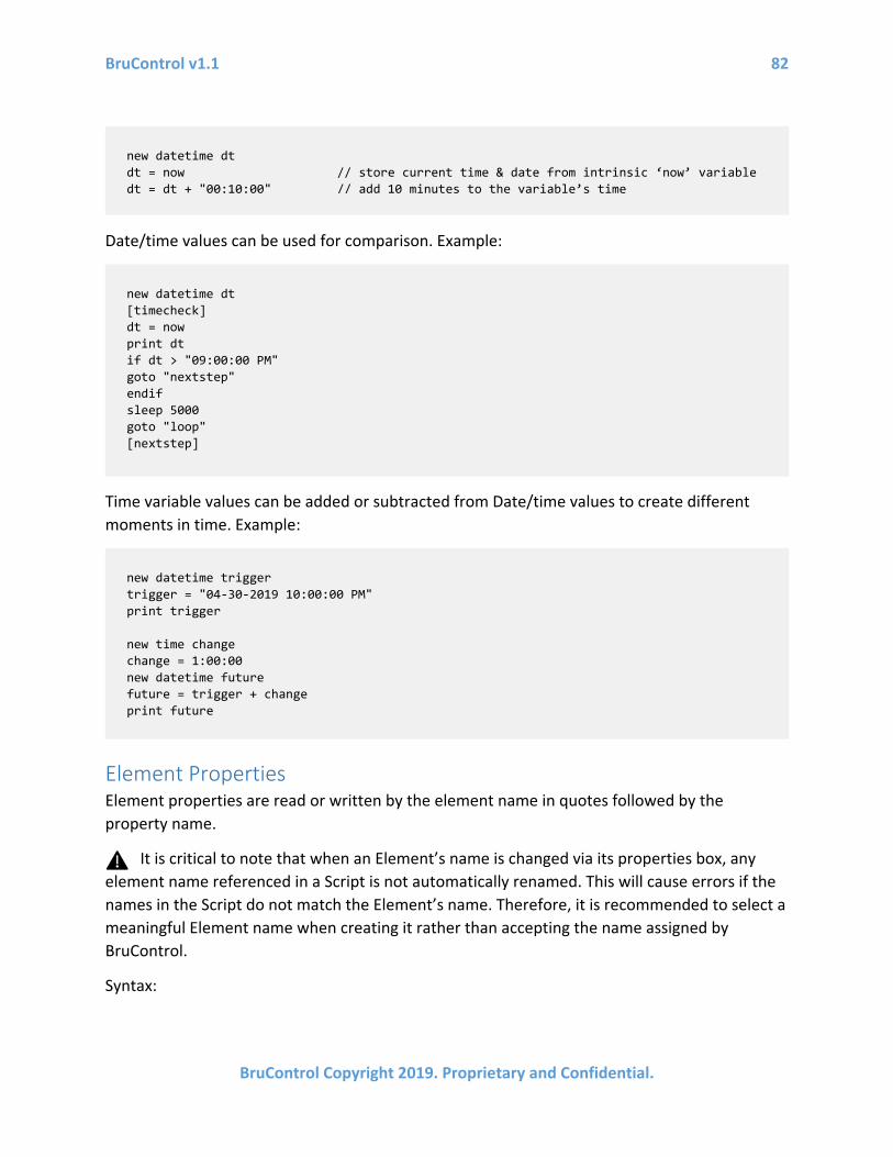
BruControl v1.1 82
BruControl Copyright 2019. Proprietary and Confidential.
Date/time values can be used for comparison. Example:
Time variable values can be added or subtracted from Date/time values to create different moments in time. Example:
Element Properties Element properties are read or written by the element name in quotes followed by the property name.
It is critical to note that when an Element’s name is changed via its properties box, any element name referenced in a Script is not automatically renamed. This will cause errors if the names in the Script do not match the Element’s name. Therefore, it is recommended to select a meaningful Element name when creating it rather than accepting the name assigned by BruControl.
Syntax:
new datetime dt dt = now // store current time & date from intrinsic ‘now’ variable dt = dt + "00:10:00" // add 10 minutes to the variable’s time
new datetime dt [timecheck] dt = now print dt if dt > "09:00:00 PM" goto "nextstep" endif sleep 5000 goto "loop" [nextstep]
new datetime trigger trigger = "04-30-2019 10:00:00 PM" print trigger new time change change = 1:00:00 new datetime future future = trigger + change print future

BruControl v1.1 83
BruControl Copyright 2019. Proprietary and Confidential.
“element” property = value, where element is the element name, property is the property associated with the element, and value is the value being assigned to the element/property pair.
Example:
The following Element properties, applicable values in parentheses are available:
• All Elements o Name (string) o Visibility (default/visible/hidden/hiddenlocked) o DisplayText (string) o Background (1, 2, or 3)
• All Device Elements o Enabled (true/false) o Connected (true/false)
• Digital Output o ActiveLow (true/false) o State (true/false) o OneShot (number) o OneShotDirection (0/1, where 0 = ON-> OFF and 1 = OFF -> ON)
• Digital Input o ActiveLow (true/false) o Value (true/false)
• Duty Cycle o DutyCycle (number) o Interval (number) o Value (true/false)
• Analog Input o PollRate (number) o AvgWeight (number) o RawValue (uncalibrated number) o Value (calibrated number)
• Analog Output o Value (number)
• Counter o SamplingPeriod (number) o Total (number)
"Analog In 1" Enabled = true "Analog In 1" PollRate = 500 "Digital Output 1" State = off "Hysteresis 1" Target = 45

BruControl v1.1 84
BruControl Copyright 2019. Proprietary and Confidential.
o RawRate (uncalibrated number) o Rate (calibrated number)
• 1-Wire o SensorIndex (number) o Unit (Fahrenheit or Celsius) o RawValue (uncalibrated number) o Value (calibrated number)
• Hysteresis o InputPortID (number) o Target (number) o OnOffset (number) o OnDelay (number) o Value (true/false)
• PID o InputPortID (number) o Target (number) o Kp (number) o Ki (number) o Kd (number) o Reversed (true/false) o CalcTime (number) o OutTime (number) o MaxIntegral (number) o MaxOutput (number) o RawValue (uncalibrated number) o Value (calibrated number)
• Deadband o InputPortID (number) o Target (number) o DeadbandOffset (number) o InnerBandOffset (number) o InnerBandDrive (number) o OuterBandDrive (number) o InitialOutput (number) o Reversed (true/false) o CalcTime (number) o OutTime (number) o RawValue (uncalibrated number) o Value (calibrated number)
• SPI Sensor Input o PollRate (number) o AvgWeight (number) o RawValue (uncalibrated number)
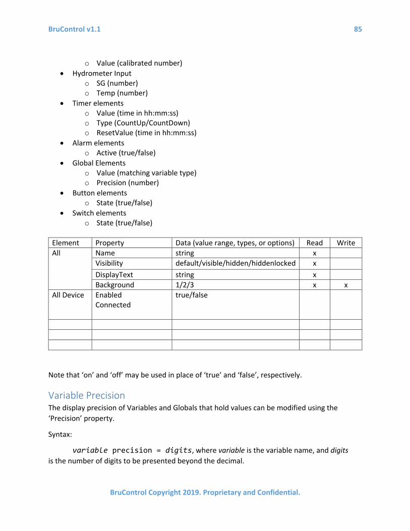
BruControl v1.1 85
BruControl Copyright 2019. Proprietary and Confidential.
o Value (calibrated number) • Hydrometer Input
o SG (number) o Temp (number)
• Timer elements o Value (time in hh:mm:ss) o Type (CountUp/CountDown) o ResetValue (time in hh:mm:ss)
• Alarm elements o Active (true/false)
• Global Elements o Value (matching variable type) o Precision (number)
• Button elements o State (true/false)
• Switch elements o State (true/false)
Element Property Data (value range, types, or options) Read Write All Name string x
Visibility default/visible/hidden/hiddenlocked x DisplayText string x Background 1/2/3 x x
All Device Enabled Connected
true/false
Note that ‘on’ and ‘off’ may be used in place of ‘true’ and ‘false’, respectively.
Variable Precision The display precision of Variables and Globals that hold values can be modified using the ‘Precision’ property.
Syntax:
variable precision = digits, where variable is the variable name, and digits is the number of digits to be presented beyond the decimal.
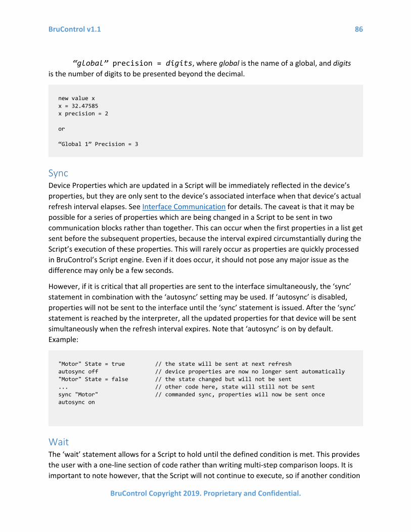
BruControl v1.1 86
BruControl Copyright 2019. Proprietary and Confidential.
“global” precision = digits, where global is the name of a global, and digits is the number of digits to be presented beyond the decimal.
Sync Device Properties which are updated in a Script will be immediately reflected in the device’s properties, but they are only sent to the device’s associated interface when that device’s actual refresh interval elapses. See Interface Communication for details. The caveat is that it may be possible for a series of properties which are being changed in a Script to be sent in two communication blocks rather than together. This can occur when the first properties in a list get sent before the subsequent properties, because the interval expired circumstantially during the Script’s execution of these properties. This will rarely occur as properties are quickly processed in BruControl’s Script engine. Even if it does occur, it should not pose any major issue as the difference may only be a few seconds.
However, if it is critical that all properties are sent to the interface simultaneously, the ‘sync’ statement in combination with the ‘autosync’ setting may be used. If ‘autosync’ is disabled, properties will not be sent to the interface until the ‘sync’ statement is issued. After the ‘sync’ statement is reached by the interpreter, all the updated properties for that device will be sent simultaneously when the refresh interval expires. Note that ‘autosync’ is on by default. Example:
Wait The ‘wait’ statement allows for a Script to hold until the defined condition is met. This provides the user with a one-line section of code rather than writing multi-step comparison loops. It is important to note however, that the Script will not continue to execute, so if another condition
new value x x = 32.47585 x precision = 2 or “Global 1” Precision = 3
"Motor" State = true // the state will be sent at next refresh autosync off // device properties are now no longer sent automatically "Motor" State = false // the state changed but will not be sent ... // other code here, state will still not be sent sync "Motor" // commanded sync, properties will now be sent once autosync on

BruControl v1.1 87
BruControl Copyright 2019. Proprietary and Confidential.
must be evaluated, an If-Else loop should be employed, or another Script should be run concurrently. The conditions can be named elements properties, as listed above. The valid comparison operators are ‘==’, ‘!=’ , ‘>=’, ‘>’, ‘<=’, ‘<’ for equals, not equals, greater than or equals, greater than, less than or equals, and less than respectively. Note that equals requires double equals signs. A timeout can be added by adding a time delay in milliseconds after the condition.
Syntax:
wait “element” property {comparison} value [timeout], where element is the element name, property is the property associated with the element, {comparison} is an applicable operator (above), value is the comparison value, and timeout is an optional failsafe time.
Examples:
If-Else ‘if’ and ‘else’ statements are supported for comparisons. They must be terminated with an ‘endif’ statement. The ‘if’ statement can be used to compare variables, element properties or immediate values. The valid comparison operators are ‘==’, ‘!=’, ‘>=’, ‘>’, ‘<=’, ‘<’ for equals, not equals, greater than or equals, greater than, less than or equals, and less than respectively. Note that equals comparators require double-equals signs.
Syntax:
if “element” property {comparison} value, where element is the element name, property is the property associated with the element, {comparison} is an applicable operator (above), and value is the comparison value.
if variable {comparison} value, where variable is the variable name, {comparison} is an applicable operator (above), and value is the comparison value.
if variable {comparison} variable, where first and second variable are two different variable names, and {comparison} is an applicable operator (above).
Example:
wait "Analog In 1" Value >= 50 // pause until the value equals or exceeds 50 wait "Alarm" Active == true // waits until alarm is active wait "Alarm" Active == true 2000 // waits until alarm is active, or until 2s elapses wait "Timer" Value > 00:00:05 // waits until the timer exceeds 5 seconds
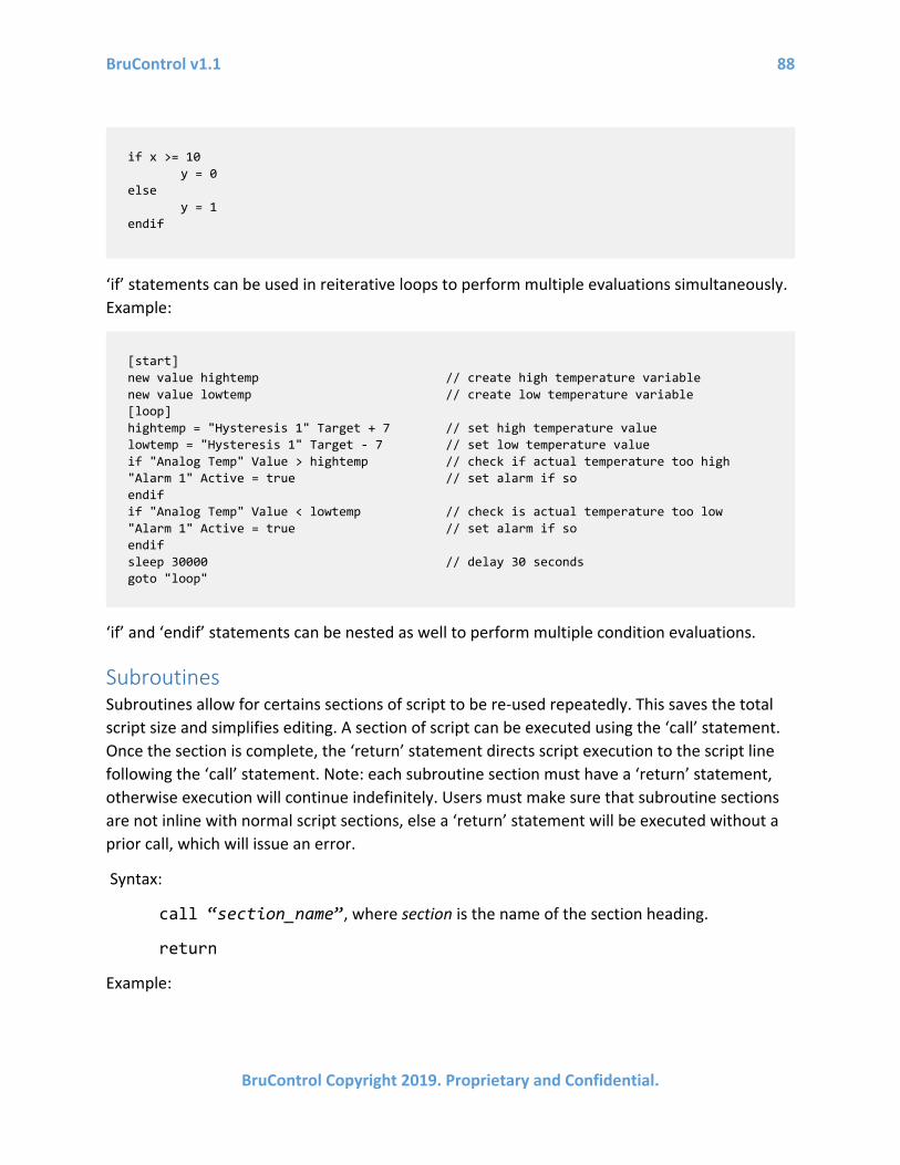
BruControl v1.1 88
BruControl Copyright 2019. Proprietary and Confidential.
‘if’ statements can be used in reiterative loops to perform multiple evaluations simultaneously. Example:
‘if’ and ‘endif’ statements can be nested as well to perform multiple condition evaluations.
Subroutines Subroutines allow for certains sections of script to be re-used repeatedly. This saves the total script size and simplifies editing. A section of script can be executed using the ‘call’ statement. Once the section is complete, the ‘return’ statement directs script execution to the script line following the ‘call’ statement. Note: each subroutine section must have a ‘return’ statement, otherwise execution will continue indefinitely. Users must make sure that subroutine sections are not inline with normal script sections, else a ‘return’ statement will be executed without a prior call, which will issue an error.
Syntax:
call “section_name”, where section is the name of the section heading.
return
Example:
if x >= 10 y = 0
else y = 1
endif
[start] new value hightemp // create high temperature variable new value lowtemp // create low temperature variable [loop] hightemp = "Hysteresis 1" Target + 7 // set high temperature value lowtemp = "Hysteresis 1" Target - 7 // set low temperature value if "Analog Temp" Value > hightemp // check if actual temperature too high "Alarm 1" Active = true // set alarm if so endif if "Analog Temp" Value < lowtemp // check is actual temperature too low "Alarm 1" Active = true // set alarm if so endif sleep 30000 // delay 30 seconds goto "loop"

BruControl v1.1 89
BruControl Copyright 2019. Proprietary and Confidential.
Timers Timer Elements can be controlled from a script. ‘Start’, ‘Stop’, ‘Reset’, and ‘Restart’ functions are available. ‘Start’ will start a stopped timer from its existing time. ‘Stop’ will stop a running timer, but not reset it. ‘Reset’ will reset a timer to its default set in its properties. It will continue to run if it was already running. ‘Restart’ will reset a timer and start it running in one step.
Syntax:
start “Timer”, where Timer is the name of the Timer Element.
stop “Timer”, where Timer is the name of the Timer Element.
reset “Timer”, where Timer is the name of the Timer Element.
restart “Timer”, where Timer is the name of the Timer Element.
A Timer Element’s current value can be read or written using the standard Element/property pairs. Example:
Alarms Alarm Elements can be activated or disactivated in a script using ‘Active’ property. Example:
[start] new value x [main] "Global 1" Value = x call "countup" sleep 3000 goto "main" [countup] x += 1 return
new time t t = "Timer 1" Value
“Alarm 1” Active = true ... “Alarm 1” Active = false ...
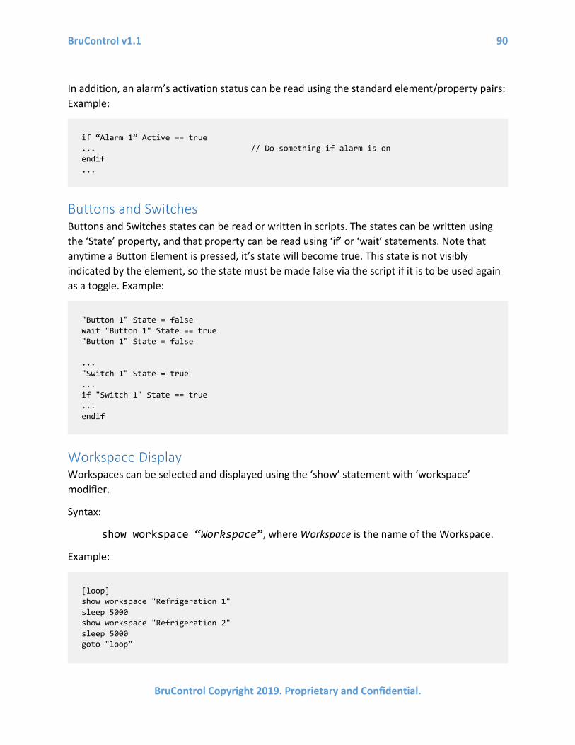
BruControl v1.1 90
BruControl Copyright 2019. Proprietary and Confidential.
In addition, an alarm’s activation status can be read using the standard element/property pairs: Example:
Buttons and Switches Buttons and Switches states can be read or written in scripts. The states can be written using the ‘State’ property, and that property can be read using ‘if’ or ‘wait’ statements. Note that anytime a Button Element is pressed, it’s state will become true. This state is not visibly indicated by the element, so the state must be made false via the script if it is to be used again as a toggle. Example:
Workspace Display Workspaces can be selected and displayed using the ‘show’ statement with ‘workspace’ modifier.
Syntax:
show workspace “Workspace”, where Workspace is the name of the Workspace.
Example:
if “Alarm 1” Active == true ... // Do something if alarm is on endif ...
"Button 1" State = false wait "Button 1" State == true "Button 1" State = false ... "Switch 1" State = true ... if "Switch 1" State == true ... endif
[loop] show workspace "Refrigeration 1" sleep 5000 show workspace "Refrigeration 2" sleep 5000 goto "loop"

BruControl v1.1 91
BruControl Copyright 2019. Proprietary and Confidential.
Script Execution Any script can start, stop, pause, or resume, other scripts, including itself, using the ‘start’, ‘stop’, ‘pause’, or ‘resume’ statements, respectively, followed by the script name in double quotes. In addition, ‘load’ can be used to prepare a Script in the interpreter’s memory, though ‘start’ causes the Script to be loaded and then run in on step. Note: scripts that do not run indefinitely should self terminate with a ‘stop’ statement, else an error will be issued.
Syntax:
start “script”, where script is the name of the script to start.
stop “script”, where script is the name of the script to stop.
pause “script”, where script is the name of the script to pause.
resume “script”, where script is the name of the script to resume.
load “script”, where script is the name of the script to load.
Example (script named “Script 1”):
Print The ‘print’ command will generate text output into the Script window ‘OUTPUT’ tab. This can be used for debugging in a Script, or to generate information during the course of a Script’s execution.
Syntax:
print “text”, where text is the text to be printed.
print variable, where variable is the variable to be printed.
Example:
[start] start "Script 2" // start another script ... // your code here stop "Script 1" // self terminate this script
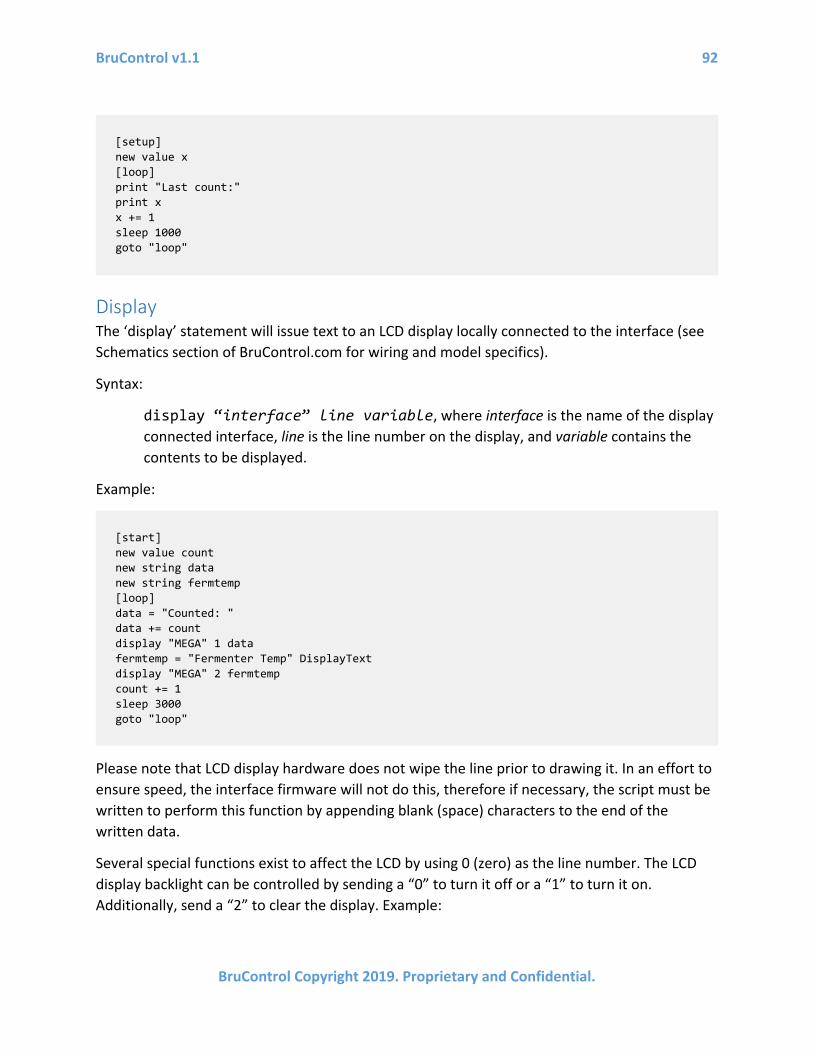
BruControl v1.1 92
BruControl Copyright 2019. Proprietary and Confidential.
Display The ‘display’ statement will issue text to an LCD display locally connected to the interface (see Schematics section of BruControl.com for wiring and model specifics).
Syntax:
display “interface” line variable, where interface is the name of the display connected interface, line is the line number on the display, and variable contains the contents to be displayed.
Example:
Please note that LCD display hardware does not wipe the line prior to drawing it. In an effort to ensure speed, the interface firmware will not do this, therefore if necessary, the script must be written to perform this function by appending blank (space) characters to the end of the written data.
Several special functions exist to affect the LCD by using 0 (zero) as the line number. The LCD display backlight can be controlled by sending a “0” to turn it off or a “1” to turn it on. Additionally, send a “2” to clear the display. Example:
[setup] new value x [loop] print "Last count:" print x x += 1 sleep 1000 goto "loop"
[start] new value count new string data new string fermtemp [loop] data = "Counted: " data += count display "MEGA" 1 data fermtemp = "Fermenter Temp" DisplayText display "MEGA" 2 fermtemp count += 1 sleep 3000 goto "loop"

BruControl v1.1 93
BruControl Copyright 2019. Proprietary and Confidential.
Note that due to the way the BruControl application handles commands to the interface, consecutive calls for the same special function code will not be transmitted to the interface. Therefore, a repeat message such as the “clear display” code will not be sent. To bypass this, different display data should be consecutively sent, prior to the refresh interval expiring. Example:
[displaycodes] new string CC // declare a new string variable CC = "0" // set the variable to “backlight off” code display "MEGA" 0 CC // turns LCD backlight off sleep 3000 // allow time for command to be sent to interface CC = "1" // set the variable to “backlight on” code display "MEGA" 0 CC // turns LCD backlight on sleep 3000 // allow time for command to be sent to interface CC = "2" // set the variable to “clear display” code display "MEGA" 0 CC // clear the entire display stop "script" // self terminate this script
... // your code here CC = “temp data” // set the variable to temporary data display “MEGA” 0 CC // queue the message CC = “2” // re-write the message with the desired data display “MEGA” 0 CC // send the data sleep 3000 // allow for the message to be sent to the interface ... // your code here

BruControl v1.1 94
BruControl Copyright 2019. Proprietary and Confidential.
Appendix Interface Preparation Micro-controller interfaces are delicate electronics and must be handled with care. Proper attention should be paid to electrostatic discharge which will render electronics useless. Ensure static electricity is discharged prior to handling.
Shields are plug-in style boards which make adding accessories simple, requiring no soldering or wiring. Shields stack upon interface boards using pin-headers and in many circumstances, multiple can be added. For example, network connectivity can be added to an interface via network shield, or both a network shield and a screw-terminal shield can be added to an interface to create an easy to wire network connectable interface. For example, here is an Ethernet v1 (WizNet 5100 based) shield plugged into (on top of) an Arduino MEGA:
When plugging shields in, be careful that the pins are appropriately aligned and squeeze together along the headers, not the middle of the boards.
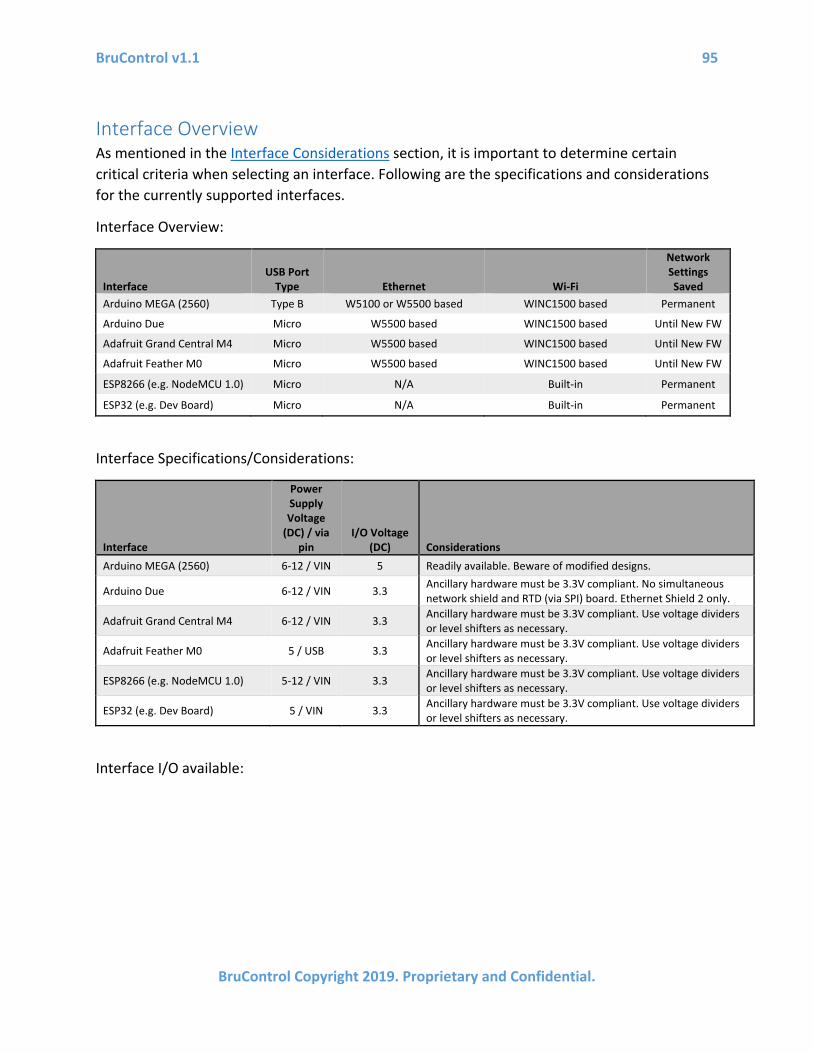
BruControl v1.1 95
BruControl Copyright 2019. Proprietary and Confidential.
Interface Overview As mentioned in the Interface Considerations section, it is important to determine certain critical criteria when selecting an interface. Following are the specifications and considerations for the currently supported interfaces.
Interface Overview:
Interface USB Port
Type Ethernet Wi-Fi
Network Settings Saved
Arduino MEGA (2560) Type B W5100 or W5500 based WINC1500 based Permanent
Arduino Due Micro W5500 based WINC1500 based Until New FW
Adafruit Grand Central M4 Micro W5500 based WINC1500 based Until New FW
Adafruit Feather M0 Micro W5500 based WINC1500 based Until New FW
ESP8266 (e.g. NodeMCU 1.0) Micro N/A Built-in Permanent
ESP32 (e.g. Dev Board) Micro N/A Built-in Permanent
Interface Specifications/Considerations:
Interface
Power Supply Voltage
(DC) / via pin
I/O Voltage (DC) Considerations
Arduino MEGA (2560) 6-12 / VIN 5 Readily available. Beware of modified designs.
Arduino Due 6-12 / VIN 3.3 Ancillary hardware must be 3.3V compliant. No simultaneous network shield and RTD (via SPI) board. Ethernet Shield 2 only.
Adafruit Grand Central M4 6-12 / VIN 3.3 Ancillary hardware must be 3.3V compliant. Use voltage dividers or level shifters as necessary.
Adafruit Feather M0 5 / USB 3.3 Ancillary hardware must be 3.3V compliant. Use voltage dividers or level shifters as necessary.
ESP8266 (e.g. NodeMCU 1.0) 5-12 / VIN 3.3 Ancillary hardware must be 3.3V compliant. Use voltage dividers or level shifters as necessary.
ESP32 (e.g. Dev Board) 5 / VIN 3.3 Ancillary hardware must be 3.3V compliant. Use voltage dividers or level shifters as necessary.
Interface I/O available:

BruControl v1.1 96
BruControl Copyright 2019. Proprietary and Confidential.
Interface
Max Digital Inputs and
Outputs Network/Serial
Max PWM (Analog) Outputs
Network/Serial
Max Analog Inputs
Network/Serial
Analog Inputs
Voltage Divisions
Max 1-wire
Temp Sensors
Max RTD
Temp Sensors
Max Counters
Arduino MEGA (2560) 45 / 49 14 / 14 16 / 16 1024 10 4 4
Arduino Due 51 / 51 12 / 12 12 / 12 4096 10 4 4
Adafruit Grand Central M4 4096 10 4 4
Adafruit Feather M0 13 / 16 8 / 11 6 / 6 4096 10 4 4
ESP8266 (e.g. NodeMCU 1.0) 9 / 9 9 / 9 1 / 1 1024 10 4 4
ESP32 (e.g. Dev Board) 4096 10 4 4
Interface Firmware Versions BruControl microcontroller interfaces run different versions of firmware depending on the microcontroller model, communication method, and/or accessory hardware. The firmware version is denoted in its filename using the following format: BruControl.version.board.options. For example: ‘BruControl.44.MEGA.ER.hex’. The board will apply to the physical model of microcontroller being used. Options vary according to their communication method and accessory hardware compatibility. Not every board and options combinations will be available. See Interface Wiring Map for specific combinations. The following tables explain the firmware letter codes:
Options code letter 1 Communication method to BruControl software E Ethernet network via v1 (W5100 based) or v2 (W5500 based) shield or board. Network
settings configured via Network Setup using BruControl InterfaceSetup Network Setup menu. BruControl can communicate via Serial via USB port and cable as long as it is not simultaneously connected to the interface via network (network takes priority).
W Wi-Fi network via default shield or board, based upon Atmel WINC1500 chipset or native ESP8266 or ESP32. Network settings configured via Network Setup using BruControl InterfaceSetup Network Setup menu. BruControl can communicate via Serial via USB port and cable as long as it is not simultaneously connected to the interface via network (network takes priority).
S Serial via USB port and cable only, using default 115200 baud rate. No network settings required. Note: some firmware versions are provided in optional baud rates, denoted by a ‘_#’ suffix, for example ‘S_230400’.
Options code letter 2 Accessory hardware compatibility (blank) None
R RTD (Resistive Temperature Device such as Pt100) via amplifier board over SPI interface. Note: All firmware versions after 44N contain RTD capability, and no option code letter 2 will be used.
Interface Recommendations While multiple interfaces and network / accessory hardware combinations have been tested to ensure proper functionality and performance, it is possible a combination will not work as expected. The current recommended interfaces are as follows:
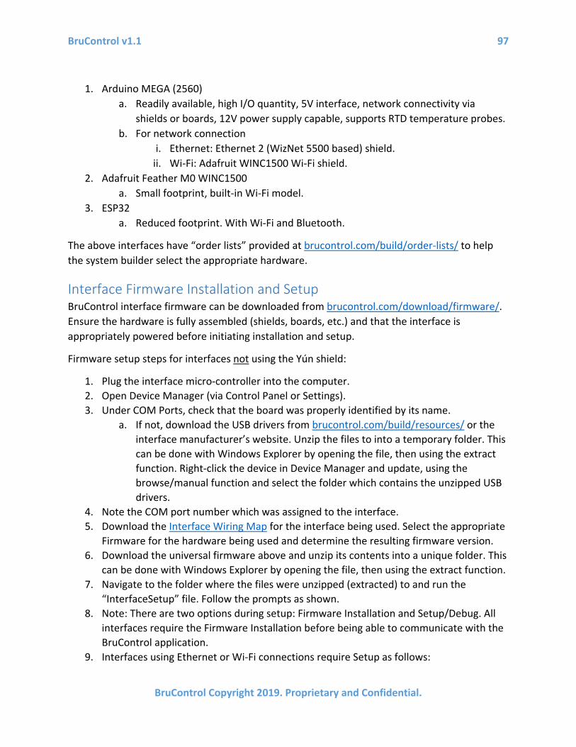
BruControl v1.1 97
BruControl Copyright 2019. Proprietary and Confidential.
1. Arduino MEGA (2560) a. Readily available, high I/O quantity, 5V interface, network connectivity via
shields or boards, 12V power supply capable, supports RTD temperature probes. b. For network connection
i. Ethernet: Ethernet 2 (WizNet 5500 based) shield. ii. Wi-Fi: Adafruit WINC1500 Wi-Fi shield.
2. Adafruit Feather M0 WINC1500 a. Small footprint, built-in Wi-Fi model.
3. ESP32 a. Reduced footprint. With Wi-Fi and Bluetooth.
The above interfaces have “order lists” provided at brucontrol.com/build/order-lists/ to help the system builder select the appropriate hardware.
Interface Firmware Installation and Setup BruControl interface firmware can be downloaded from brucontrol.com/download/firmware/. Ensure the hardware is fully assembled (shields, boards, etc.) and that the interface is appropriately powered before initiating installation and setup.
Firmware setup steps for interfaces not using the Yún shield:
1. Plug the interface micro-controller into the computer. 2. Open Device Manager (via Control Panel or Settings). 3. Under COM Ports, check that the board was properly identified by its name.
a. If not, download the USB drivers from brucontrol.com/build/resources/ or the interface manufacturer’s website. Unzip the files to into a temporary folder. This can be done with Windows Explorer by opening the file, then using the extract function. Right-click the device in Device Manager and update, using the browse/manual function and select the folder which contains the unzipped USB drivers.
4. Note the COM port number which was assigned to the interface. 5. Download the Interface Wiring Map for the interface being used. Select the appropriate
Firmware for the hardware being used and determine the resulting firmware version. 6. Download the universal firmware above and unzip its contents into a unique folder. This
can be done with Windows Explorer by opening the file, then using the extract function. 7. Navigate to the folder where the files were unzipped (extracted) to and run the
“InterfaceSetup” file. Follow the prompts as shown. 8. Note: There are two options during setup: Firmware Installation and Setup/Debug. All
interfaces require the Firmware Installation before being able to communicate with the BruControl application.
9. Interfaces using Ethernet or Wi-Fi connections require Setup as follows:
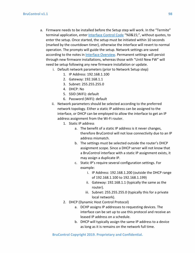
BruControl v1.1 98
BruControl Copyright 2019. Proprietary and Confidential.
a. Firmware needs to be installed before the Setup step will work. In the “Termite” terminal application, enter Interface Control Code “%0&15;”, without quotes, to enter the setup. Once started, the setup must be initiated within 10 seconds (marked by the countdown timer), otherwise the interface will revert to normal operation. The prompts will guide the setup. Network settings are saved according to the notes in Interface Overview. Permanent settings will persist through new firmware installations, whereas those with “Until New FW” will need be setup following any new firmware installation or update.
i. Default network parameters (prior to Network Setup step) 1. IP Address: 192.168.1.100 2. Gateway: 192.168.1.1 3. Subnet: 255.255.255.0 4. DHCP: No 5. SSID (WiFi): default 6. Password (WiFi): default
ii. Network parameters should be selected according to the preferred network topology. Either a static IP address can be assigned to the interface, or DHCP can be employed to allow the interface to get an IP address assignment from the Wi-Fi router.
1. Static IP address a. The benefit of a static IP address is it never changes,
therefore BruControl will not lose connectivity due to an IP address mismatch.
b. The settings must be selected outside the router’s DHCP assignment scope. Since a DHCP server will not know that a BruControl interface with a static IP assignment exists, it may assign a duplicate IP.
c. Static IP’s require several configuration settings. For example:
i. IP Address: 192.168.1.200 (outside the DHCP range of 192.168.1.100 to 192.168.1.199)
ii. Gateway: 192.168.1.1 (typically the same as the router).
iii. Subnet: 255.255.255.0 (typically this for a private local network).
2. DHCP (Dynamic Host Control Protocol) a. DCHP assigns IP addresses to requesting devices. The
interface can be set up to use this protocol and receive an leased IP address on a schedule.
b. DHCP will typically assign the same IP address to a device as long as it is remains on the network full time.

BruControl v1.1 99
BruControl Copyright 2019. Proprietary and Confidential.
c. Should a device drop off the network for a period of time, the DHCP server may assign that IP address to a new device. In that circumstance, BruControl will lost connectivity with the interface.
d. To ensure that the interface always receives the same IP address, DHCP “reservations” can be established in the router based upon the interface’s MAC address.
3. During Wi-Fi setup, the SSID and Password need be entered. a. SSID (WiFi): your Wi-Fi access point ID b. Password (WiFi): your Wi-Fi access point password
i. Note: WPA and WPA2 encrytions are supported. iii. Network connectivity issues should be debugged using the interface’s
debug control code (below). 10. Note: Anytime an IP address is changed, the host BruControl computer’s network card
may confuse the interface’s MAC address with two IP address, hindering communication. Rebooting the host computer will resolve this problem. In addition, anytime the interface is switched from Static IP address mode to DHCP mode, the interface should be reset after the network configuration is completed.
11. Note: When DHCP is enabled, the interface must be reset (restarted) after the settings are first saved.
Interface Control Codes BruControl Interfaces accept special control codes to enter setup or report debug information. These codes function via serial (USB) connection only to terminal program. This information can be reviewed using the “Termite” terminal application included in the Firmware Installation files.
1. Setup: a. To enter Setup, enter “%0&15;” (excluding quotes) into the terminal entry field
and press Enter. 2. Debug Reporting:
a. To initiate debug reporting, enter “%1&14;” (excluding quotes) into the terminal entry field and press Enter.
b. Each time this code is entered, the debug level is increased by one level. BruControl Interface Firmware provides three levels of debug reporting:
i. Level 0 indicates no reporting. ii. Level 1 indicates basic reporting.
iii. Level 2 indicates detailed reporting. c. To decrease debug reporting level, enter: “%2&17;” (excluding quotes) into the
terminal entry field and press Enter.

BruControl v1.1 100
BruControl Copyright 2019. Proprietary and Confidential.
BruControl cannot communicate with an interface via serial (USB) which has debug reporting enabled. Therefore this must be disabled (Level 0) before communicating with BruControl.
3. (Re) initialize 1-wire: a. To re-initialize the 1-wire sensor network (and report the number found on the
bus if Debug Level 1+ is enabled), enter: “%3&16;” (excluding quotes) into the terminal entry field and press Enter.
b. Alternatively, the 1-wire sensor network can be re-initialized via the BruControl Interface Communications dialog. To do so, enter: “%3” into the Transmit field and select ‘TRANSMIT’.
4. (Re) initialize LCD display: a. To initialize the LCD display (and report its connection if Debug Level 1+ is
enabled), enter: “%4&11;” (excluding quotes) into the terminal entry field and press Enter.
b. Alternatively, the LCD display can be re-initialized via the BruControl Interface Communications dialog. To do so, enter: “%4” into the Transmit field and select ‘TRANSMIT’.
5. Store interface power-on device configuration: a. To store the current enabled Device Elements, enter “%5&10;” (excluding
quotes) into the terminal entry field and press Enter. b. Alternatively, the current enabled Device Elements can be stored via the
BruControl Interface Communications dialog. To do so, enter: “%5” into the Transmit field and select ‘TRANSMIT’.
c. To disable stored devices, ensure that all Device Elements are disabled, then store the configuration.
Device Elements Enabled / Affected via Scripts Per above, the BruControl application sends messages to the interfaces to command how its pins/ports should perform. Normally, these messages are sent following changes to Device Elements conducted by the user. These messages are also sent following changes to Device Elements affected by scripts when Autosync is enabled (see Sync).
For example, a script loop might repeatedly turn a Digital Output ON. If this happens, the message will repeat with each refresh cycle, causing the output to not query its state on the next refresh cycle, therefore will not successfully display its ON or OFF state in its Device Element. Therefore, the script editor should build in logic that prevents Device Elements from being repeatedly updated. This applies to any Device Element that is repeatedly updated. In this example, the script checks for the state of a Digital Output to make sure it is OFF before setting it ON, rather than just setting it ON repeatedly.

BruControl v1.1 101
BruControl Copyright 2019. Proprietary and Confidential.
WINC1500 Wi-Fi Considerations Wi-Fi shields and boards which use the Atmel WINC1500 Wi-Fi module have some considerations which should be addressed.
First, these modules contain their own firmware (which is separate from the interface firmware), and boards often ship with an outdated version of that firmware. The BruControl firmware referenced in this manual is compatible with WINC1500 firmware version 19.5.2 or 19.5.4. If a Wi-Fi shield was purchased via BruControl, the firmware will be properly updated before shipment. However, if a Wi-Fi shield was purchased directly from a reseller, it should be updated. To update the firmware:
1. Download the Arduino IDE Editor from https://www.arduino.cc/en/Main/Software. Download the ZIP file for non-admin installations. This is portable and will not require a formal installation.
2. Unzip the files into a temporary folder and run the ‘arduino.exe’ file. 3. Connect the interface (with shield attached) via USB cable. 4. Under ‘Tools’, select the appropriate board type and COM port. 5. Under ‘File… Examples… WiFi101…’, select ‘Firmware Updater’. 6. Select ‘Sketch…Upload’. 7. After it has been uploaded, select ‘Tools… WiFi101 Firmware Updater’ 8. Select the appropriate COM port and version, then select the ‘Update Firmware’ button. 9. Install the interface firmware per above.
Second, Wi-Fi shields which use these modules draw a relatively large amount of power. Note: for built-in modules, the manufacturer will disclose any specific power requirements. Expect approximately 200 mA at 5V, which means for example that when powered via an Arduino MEGA 2560’s 5V regulator (5V pin), almost half of its available power will be used. Therfore, if powering other accessories via the 5V pin like RTD amplifiers, sensors, or sourcing power to active high devices (like relay boards), this limit may be exceeded. In that case, those devices should be powered via an external 5V power supply. All power supplies’ grounds should be tied together in a ‘star’ pattern to make sure voltage references are correct.
[loop] ... if “Digital Output 1” state == off “Digital Output 1” state = on endif ... sleep 3000 goto “loop”

BruControl v1.1 102
BruControl Copyright 2019. Proprietary and Confidential.
SPI Sensor Considerations In firmware versions prior to 44N, RTD (via SPI) capable ports were actively pulled up to high voltage upon interface start-up. This ensured that RTD devices on the SPI bus did not communicate when they were intended. As a result, RTD ports were limited to a fixed number of certain ports. Starting in version 44N, the ports are not pulled up. This will allow for any digital I/O port to be used as an RTD port. Certain RTD amplifier boards contain built-in pull-up resistors which will ensure no communication until commanded. The system builder should make sure that any SPI sensor contains these pull-up resistors on board, otherwise add them (10 – 47k should be adequate).
BruControl as a Server BruControl is intended to be run as an “automation server”, meaning it should run full time. However, for applications where it is only needed when a machine is being used, shutting it down after is acceptable. When device elements are actively running, BruControl will request if those device elements should be disabled upon shutdown. If devices are not disabled, they will continue to run in their steady-state mode. For example, a Digital Output which is ON will remain ON, or a Hysteresis device which is running to hold a temperature will continue to do so.
Windows automatically applies updates to add features and reduce software bugs, but in doing so will often restart its host computer. This may be undesirable for a server system, in which case the automatic restarts can be disabled via the Task Scheduler and/or Registry. See https://tunecomp.net/disable-automatic-reboot-after-updates-installation-in-windows-10/ for guidance.
Power Failures BruControl interfaces are micro-controllers which do not have dynamic non-volatile memory, meaning their current running states (devices, etc.) are lost when their power drops or they are reset via a reset button or strong electromagnetic interference. If BruControl is running, the interface’s current running state will be restored once they connect. However, if it is not, or a communication interruption occurs, the interface will not resume its current running state. In important applications where power-failure tolerance is required, a battery backup is recommended. Certain interfaces, such as the Adafruit Feather M0 WINC1500 have native battery ports, which allow a Li-Po battery to be connected. These keep the battery charged, and draw upon the battery power when the supply power drops. Other interfaces such as the Arduino MEGA would require support from additional hardware, such as the Adafruit PowerBoost (https://www.adafruit.com/product/2465). Alternatively, a UPS of appropriate design and power storage can be implemented into the control system hardware. Another option to handle power failures is to store power-on devices configurations, below.
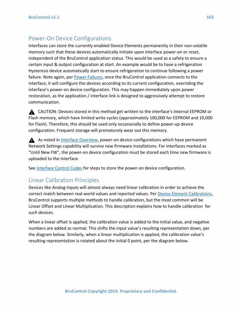
BruControl v1.1 103
BruControl Copyright 2019. Proprietary and Confidential.
Power-On Device Configurations Interfaces can store the currently enabled Device Elements permanently in their non-volatile memory such that these devices automatically initiate upon interface power-on or reset, independent of the BruControl application status. This would be used as a safety to ensure a certain input & output configuration at start. An example would be to have a refrigeration Hysteresis device automatically start to ensure refrigeration to continue following a power failure. Note again, per Power Failures, once the BruControl application connects to the interface, it will configure the devices according to its current configuration, overriding the interface’s power-on device configuration. This may happen immediately upon power restoration, as the application / interface link is designed to aggressively attempt to restore communication.
CAUTION: Devices stored in this method get written to the interface’s internal EEPROM or Flash memory, which have limited write cycles (approximately 100,000 for EEPROM and 10,000 for Flash). Therefore, this should be used only occasionally to define power-up device configuration. Frequent storage will prematurely wear out this memory.
As noted in Interface Overview, power-on device configurations which have permanent Network Settings capability will survive new firmware installations. For interfaces marked as “Until New FW”, the power-on device configuration must be stored each time new firmware is uploaded to the interface.
See Interface Control Codes for steps to store the power-on device configuration.
Linear Calibration Principles Devices like Analog Inputs will almost always need linear calibration in order to achieve the correct match between real-world values and reported values. Per Device Element Calibrations, BruControl supports multiple methods to handle calibration, but the most common will be Linear Offset and Linear Multiplication. This description explains how to handle calibration for such devices.
When a linear offset is applied, the calibration value is added to the initial value, and negative numbers are added as normal. This shifts the input value’s resulting representation down, per the diagram below. Similarly, when a linear multiplication is applied, the calibration value’s resulting representation is rotated about the initial 0 point, per the diagram below.
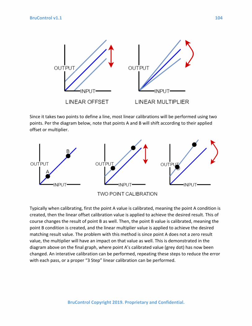
BruControl v1.1 104
BruControl Copyright 2019. Proprietary and Confidential.
Since it takes two points to define a line, most linear calibrations will be performed using two points. Per the diagram below, note that points A and B will shift according to their applied offset or multiplier.
Typically when calibrating, first the point A value is calibrated, meaning the point A condition is created, then the linear offset calibration value is applied to achieve the desired result. This of course changes the result of point B as well. Then, the point B value is calibrated, meaning the point B condition is created, and the linear multiplier value is applied to achieve the desired matching result value. The problem with this method is since point A does not a zero result value, the multiplier will have an impact on that value as well. This is demonstrated in the diagram above on the final graph, where point A’s calibrated value (grey dot) has now been changed. An interative calibration can be performed, repeating these steps to reduce the error with each pass, or a proper “3 Step” linear calibration can be performed.

BruControl v1.1 105
BruControl Copyright 2019. Proprietary and Confidential.
To do this, first a linear offset is applied to get point A’s result to equal zero. The difference now between its actual desired value and zero should be noted as ‘z’. Next, point B is calibrated by applying a linear multiplier, with its resulting value calibrated to be a value that is its desired value minus z. Finally, a third calibration is applied, using a linear offset to shift point A back to the desired value. This is done by setting z as the offset value. Future calibrations are made simple using this method as well.
Analog Input Considerations The analog inputs of an interface divide the voltage on the respective pin into one of several thousand steps (see Analog Inputs). These inputs are very sensitive to minor voltage changes, with for example, a 3.3V reference divided into 4096 steps equates to 0.805 millivolts-per-step. This level of sensitivity will invariably result in reading variations even when the input voltage circuit is not changing. This is a result of ambient electrical noise and built-in error in the analog-to-digital converter circuit on the interface. Filtering should be employed to reduce noise and create a reading that is more steady over time.
First, electrical filtering and isolation should be implemented on all circuits. Isolation refers to placing and routing low voltage devices and wiring separate from high voltage wiring. Shielded wiring can also help. Usage of filter inductors and capacitors are also highly recommended.
Second, software filtering or “digital smoothing” should also be implanted on all inputs where reading speed is not critical. The ‘Avg Weight’ property of an analog input affects its digital smoothing, with lower numbers (~20%) yielding more consistent readings but react to changes more slowly. Conversely, higher averages (~75%) respond to changes more rapidly but also will report more variation from noise. High impedance sensors like thermistors are more prone to noise, therefore should have an ‘Avg Weight’ of around 10-30%, whereas low impedance sensors like proportional voltage sensors can have an average weight which is higher, such as 75% or more. Capacitors should always be placed in parallel with high impedance sensors to reduce noise and ensure rapid accurate readings.

BruControl v1.1 106
BruControl Copyright 2019. Proprietary and Confidential.
For example, High impedance sensors like thermistors are more prone to noise, therefore should have an ‘Avg Weight’ of around 10-30%, whereas low impedance sensors like proportional voltage sensors can have an average weight which is higher, such as 75% or more.
For example, here is a graph of a sensor where the ‘Avg Weight’ property was changed from 100% to 20% at the arrow:
Upgrade From v1.0 When upgrading from v1.0 to v1.1, it is important to follow these instructions completely:
1. Backup existing BruControl data folder. This folder is located in the user’s “Documents” folder. Make a duplicate of this folder and copy it to a safe location, preferably on another drive (USB key, network share, cloud store, etc.).
2. Extract the files into a new, unique BruControl application folder. Do not delete the previous version in case you need to restore.
3. Close the existing BruControl application if running, and make sure to select “DISABLE ALL AND SHUTDOWN”.
4. v1.1 includes updated Interface Wiring Maps. In some circumstances, interface wiring maps have been changed (for example, RTD specific maps have been eliminated). The installer must compare the existing v1.0 Interface Wiring Map with the v1.1 version to ensure the existing interface wiring, pin and port definitions match the v1.1 map. If any of the wiring, pins, or ports are different:
a. The installer should correct the interface wiring. b. The Device Elements which reference incorrect ports should be deleted and re-
created to address the correct ports. c. Alternatively, v1.0 Interface Definition files (.brumc files) are included in a
“v1_Interface_Definitions” folder. i. To use these maps, copy the desired Interface Definition file from the
“v1_Interface_Definitions” folder to the BruControl installation folder, overwriting the v1.1 Interface Definition file.

BruControl v1.1 107
BruControl Copyright 2019. Proprietary and Confidential.
5. Execute the new version of BruControl, and carefully check that all Elements, Scripts, Workspaces, etc. are functioning as expected. Restore the previously back-ed up folder if needed.
Version History V1.1 includes the following updates:
• Various bug & missing documented functionality fixes • User interface update
o Menu updated o Settings icon moved to right o SVG theme called "The Bezier" faster drawing and good for high resolution
displays - RECOMMEND USING o Minimize to system tray option
• Element display o Value
Digital gauge Circular gauge Linear gauge
o State LED indicator OFF/ON custom text
• Elements o Ability to move across workspaces o Background images
Multiple can be assigned and selected Backgrounds can be changed via script (see scripts below)
• Device Elements o TILT sensor Device Element (ESP32 only, on virtual ports 220 – 224) o Deadband Device Element
• Properties dialogs o APPLY button to inspect changes o Touchscreen button keypad for all numerical dialogs
• Interfaces o Analog resolution beyond 10-bit (per interface capability) PENDING FIRMWARE
UPDATE o Interfaces can be disabled in Interfaces Settings dialog via checkbox
• Timers o State and value (within 30 seconds) saved upon application restart o Spans now include days

BruControl v1.1 108
BruControl Copyright 2019. Proprietary and Confidential.
o Two alarm thresholds can be set natively (no script required) • Scripts
o Wait statements with timeouts can be stepped over during pause mode o Commands
Element Backgrounds • Syntax: "Element 1" background = 1
Workspace display • Syntax: show workspace “Workspace”
o Subroutines Sections of code can be re-used for simplicity Syntax:
• To start execution of section: call “section_name” • To return to call point: return
o Real time functions New date/time variable value
• Declare date/time variable o Syntax: new datetime my_date
• Assign a time o Syntax: my_date = “09:05:45”
• Current time o Syntax: my_date = now
o Scripts are stopped in application startup, not paused • Data Exchange
o Data exchange in and out of Globals o Professional license required
• Configuration files o Automatic daily backups with 30-day history in BruControl/Config Backup folder o To restore, manual copy/paste/rename is required
• Calibration o Added Kelvin -> Fahrenheit o Added lookup table o Added Divider (rather than using inverse multiply)
• Variables – MAJOR CHANGE o “Inspector Elements”
Replace “Variable” Elements Same operation as before: display values of discrete in-script variables
o “Global” Elements New type of element which stores a value, text, time, date/time Value exists in the element, not in a script

BruControl v1.1 109
BruControl Copyright 2019. Proprietary and Confidential.
Value lasts in perpetuity (saved inside configuration files) Values saved into configuration file for perpetuity Can be accessed via multiple scripts (also to share data across scripts)
o Previous in-script variables Operate as before
Technical Assistance Technical assistance, troubleshooting, and build resources are available via:
1. Website: BruControl.com 2. Community Forum: Brucontrol.com/community 3. HomeBrewTalk Forum: HomeBrewTalk 4. Email BruControl Technical Support: [email protected]