process for system architecture and requirements...
TRANSCRIPT


PROCESS FOR
SYSTEM ARCHITECTURE
AND REQUIREMENTS
ENGINEERING

Also Available from DORSET HOUSE PUBIJSHING Co.Adaptive Software Development:A Collaborative Approach to Managing Complex Systemsby James A. Highsmith III foreword by Ken OrrISBN: 0-932633-40-4 Copyright ©2000 392 pages, softcover
Complete Systems Analysis: The Workbook, the Textbook, the Answersby James & Suzanne Robertson foreword by Tom DeMarcoISBN: 0-932633-50-1 Copyright ©1998,1994 624 pages, softcover
Designing Quality Databases with IDEF1X Information Modelsby Thomas A. Bruce foreword by John A. ZachmanISBN: 0-932633-18-8 Copyright ©1992 584 pages, hardcover
Exploring Requirements: Quality Before Designby Donald C. Gause and Gerald M. WeinbergISBN: 0-932633-13-7 Copyright ©1989 320 pages, hardcover
The Practical Guide to Business Process Reengineering Using IDEFOby Clarence G. Feldmann foreword by John V. TiesoISBN: 0-932633-37-4 Copyright ©1998 240 pages, softcover
The Psychology of Computer Programming: Silver Anniversary Editionby Gerald M. Weinberg ISBN: 0-932633-42-0 Copyright ©1998 360 pages, softcover
Quality Software Management, Vol. 4: Anticipating Changeby Gerald M. WeinbergISBN: 0-932633-32-3 Copyright ©1997 504 pages, hardcover
Surviving the Top Ten Challenges of Software Testing: A People-Oriented Approachby William E. Perry and Randall W. RiceISBN: 0-932633-38-2 Copyright ©1997 216 pages, softcover
Strategies for Real-Time System Specificationby Derek J. Hatley and Imtiaz A. Pirbhai foreword by Tom DeMarcoISBN: 0-932633-11-0 Copyright ©1988, 1987 408 pages, hardcover
Find Out More about These and Other DH Books:Contact us to request a Book & Video Catalog and a free issue of The Dorset HouseQuarterly, or to confirm price and shipping information.
DORSET HOUSE PUBLISHING Co., INC.353 West 12th Street New York, NY 10014 USA1-800-DH-BOOKS (1-800-342-6657) 212-620-4053 fax:[email protected] http://www.dorsethouse.com

PROCESS FOR
SYSTEM ARCHITECTURE
AND REQUIREMENTS
ENGINEERING
Derek Hatley Peter Hruschka Imtiaz Pirbhai
Dorset House Publishing353 West 12th StreetNew York, NY 10014

Library of Congress Cataloging-in-Publication Data
Hatley, Derek J., 1934-Process for system architecture and requirements engineering / Derek Hatley, Peter
Hruschka, Imtiaz Pirbhai.p. cm.
ISBN 0-932633-41-2 (pbk.)1. System design. 2. System analysis. I. Hruschka, Peter, 1951- II. Pirbhai, Imtiaz A.,
1953-111. Title.
QA76.9.S88 H3735 2000005.1 '2»dc21
00-060997
All product and service names appearing herein are trademarks or registeredtrademarks or service marks or registered service marks of their respective own-ers and should be treated as such.
Cover Design: David W. McClintockCover Graphic: Detail from Figure 11.2Cover Author Photographs: Hatley photo: O'Connor-Rice Studios; Hruschka
photo: James Robertson; Pirbhai photo: Stewart Auer.
Copyright © 2000 by Derek J. Hatley, Peter Hruschka, and Shams Pirbhai. Publishedby Dorset House Publishing Co., Inc., 353 West 12th Street, New York, NY 10014.
All rights reserved. No part of this publication may be reproduced, stored in a retrievalsystem, or transmitted, in any form or by any means, electronic, mechanical, photocopy-ing, recording, or otherwise, without prior written permission of the publisher.
Distributed in the English language in Singapore, the Philippines, and Southeast Asiaby Alkem Company (S) Pte. Ltd., Singapore; in the English language in India,Bangladesh, Sri Lanka, Nepal, and Mauritius by Prism Books Pvt., Ltd., Bangalore,India; and in the English language in Japan by Toppan Co., Ltd., Tokyo, Japan.
Printed in the United States of America
Library of Congress Catalog Number: 00-060997
ISBN: 0-932633-41-2 1211 10987654321
Digital release by Pearson Education, Inc., June, 2013

DEDICATION
A wonderful friend and fine colleague of ours started thisbook: He laid out the basic ideas and the structure, anddeveloped some of the materials. Then, suddenly and unex-pectedly, and in the prime of his life, he passed away. Wemiss him sorely.
We are grateful to his brother Shams for providing uswith the original materials, and honored at being given theopportunity to complete the project. It is not the same book itwould have been had he completed it, but we hope it comessomewhere close to his expectations.
It is unusual to dedicate a book to one of its authors, butthese are unusual and tragic circumstances. So, we humblydedicate Process for System Architecture and RequirementsEngineering to the memory of a true visionary in the field ofsystem development:
Imtiaz Pirbhai.

ACKNOWLEDGMENTS
We are deeply indebted to Kamal Hammoutene, Alan Hecht,Mark Maier, Vince Peterson, and Tanehiro Tatsuta for theirpainstaking reviews of the draft of this book and for theirexcellent comments and suggestions. The book is far betterfor their efforts.
We thank the editorial staff at Dorset House Publish-ing—Nuno Andrade, Debbie Carter, David Crohn, WendyEakin, Bob Hay, Mike Lumelsky, David McClintock, MattMcDonald, and Mike Richter—for the excruciating detailwith which they examined, tore apart, and reconstructedour English. This, too, greatly improved the final product.
Finally, we thank the many participants in our seminarsand workshops for their enthusiasm and for teaching us atleast as much as we taught them.

Contents
Figures xv
Part I Concepts 1
Chapter 1 Introduction 31 . 1 PURPOSE AND SCOPE 31.2 THE SYSTEM DEVELOPMENT PROCESS 41.3 UNDERLYING PRINCIPLES 41 .4 WHAT'S IN A NAME? 51.5 AUDIENCE FOR AND STRUCTURE OF THE BOOK 61.6 A PARTICIPATIVE CASE STUDY ON THE WEB 71.7 A CAVEAT 8
Chapter 2 What Is a System? 92.1 SYSTEM CHARACTERISTICS 9
2.1.1 Introduction to Systems 92.1.2 System Hierarchies 112.1.3 Multiple Hierarchies 1 42.1.4 System Networks 1 42.1.5 System Life Cycle and Errors 1 52.1.6 Order and Chaos 1 62.1.7 System Predictability 1 72.1.8 Dealing with Complexity 1 7
2.2 VIEWS OF A SYSTEM 182.2.1 The Processing View 1 92.2.2 The Processor View 202.2.3 The What/ How View 2 1
vii

viii CONTENTS
2.2.4 The Level of Intelligence View 222.2.5 The Static /Dynamic View 23
2.3 SYSTEM REQUIREMENTS 242.3.1 The Sources of Requirements 24
2.3.1.1 Customers 24
2.4
Chapter3.1
3.2
3.3
3.4
2.2.2.2.
2.3.1.2 Users 252.3.1.3 Managers 252.3.1.4 Industry Standards 252.3.1.5 The Development Process 262.3.1.6 Others 26
3.2 What Exactly Are Requirements, Anyway? 263.3 A Model of Requirements 283.4 Quality 363.5 Requirement Management and Analysis 37
2.3.5.1 Requirement Gathering 372.3.5.2 Requirement Integrity Analysis 382.3.5.3 Requirement Feasibility Analysis 382.3.5.4 Requirement Detailing 382.3.5.5 Requirement Deriving 392.3.5.6 Requirement Categorizing 39
SYSTEM SUMMARY 40
3
A
A Framework for Modeling Systems 41MODEL FRAMEWORK 4 1
MODELS IN GENERAL 4 13.3.
2. 1 Models Are Useful Abstractions 422.2 Model Representations and Reuse 43
EXPLOITING SYSTEM HIERARCHIES 453.3.3.3.
3. 1 Why Exploit Hierarchies? 463.2 What Are the Benefits and Pitfalls of Layered Systems? 463.3 How Many Models? 473.4 Where Do We Stop? 48
EXPLOITING THE WHAT/ How CLASSIFICATION 493.4. 1 Separation of What and How 503.4.2 The Architecture Template 5 13.4.3 Using the Architecture Template 53
3.5 EXPLOITING THE INFORMATION/MATERIAL/ENERGY CLASSIFICATION 553.5.1 A Generic Subsystem Structure 553.5.2 Categories of a Deliverable System 573.5.3 Categories of a People System 60
3.6 LAYERED MODELS: THE TRUTH AT LAST! 603.6.1 Aggregation /Decomposition Relationship in Models 643.6.2 Abstraction/Detailing Relationship in Models 65

CONTENTS ix
3.6.3 Supertype/Subtype Relationship in Models 663.6.4 Controlling/Controlled Relationship in Models 673.6.5 Layered Models Summary 68
3.7 MODEL FRAMEWORK SUMMARY 70
Chapter 4 System Development Models 724. 1 OVERVIEW 724.2 ARCHITECTURE MODEL 74
4.2.1 Introduction 744.2.2 Basic Modeling Elements 76
4.2.2.1 Architecture Module 774.2.2.2 Terminator 784.2.2.3 Architecture Flow 794.2.2.4 Message 814.2.2.5 Flows and Messages 834.2.2.6 Inheritance Relationship 854.2.2.7 Architecture Interconnect 86
4.2.3 Context Diagram 874.2.4 Networks and Hierarchies 904.2.5 Architecture Communication Model 92
4.2.5.1 Architecture Flow Diagram 944.2.5.2 Architecture Message Diagram — Network Style 974.2.5.3 Architecture Message Diagram — Hierarchy Style 994.2.5.4 Architecture Module Specification 1014.2.5.5 Message Specification 102
4.2.6 Architecture Interconnect Model 1034.2.6.1 Architecture Interconnect Diagram 1 044.2.6.2 Architecture Interconnect Specification 1 06
4.2.7 Architecture Inheritance Model 1064.2.7.1 Module Inheritance Diagram 107
4.2.8 Architecture Dictionary 1084.2.9 Architecture Model Balancing 1 10
4.2.9. 1 Architecture Message Diagram Balancing 1114.3 REQUIREMENTS MODEL 112
4.3.1 Introduction 1124.3.2 Entity Model 115
4.3.2.1 Basic Modeling Elements 1164.3.2.2 Attribute 1164.3.2.3 Entity Class 1164.3.2.4 Relationship 1184.3.2.5 Special Relationships 1214.3.2.6 Class Diagram 1254.3.2.7 Entity Class Specification 1264.3.2.8 Relationship Specification 1274.3.2.9 Attribute Specification 129
4.3.3 Process Model 130
x CONTENTS
4.3.3. 1 Basic Modeling Elements 1314.3.3.2 Data Flow 1314.3.3.3 Process 1334.3.3.4 Store 1344.3.3.5 Terminator 1354.3.3.6 Data Context Diagram 1354.3.3.7 Data Flow Diagram 1374.3.3.8 Detailing Diagrams 1394.3.3.9 Process Specification 141
4.3.4 Control Model 1434.3.4. 1 Control Flow 1444.3.4.2 Control Specification 1464.3.4.3 Sequential Machines — State Transition Diagrams and
State Charts 1474.3.4.4 Other Representations of Sequential Machines 1514.3.4.5 Combinational Machines — Decision Tables and
Process Activation Tables 1 534.3.5 The Control Flow Model: Basic Elements 155
4.3.5.1 Control Flow 1554.3.5.2 CSPECBar 156
4.3.6 Control Context Diagram 1564.3.7 Control Flow Diagram 157
4.3. 7. 1 Rules and Guidelines for CFDs and CSPECs 1 594.3.8 Separation of Data and Control 160
4.4 REQUIREMENTS DICTIONARY 1624.4.1 Timing Requirements 1644.4.2 Requirements Model Balancing 1664.4.3 Architecture Template and Enhanced Requirements Model 1664.4.4 Requirements Model Summary 169
4.5 REQUIREMENTS /ARCHITECTURE RELATIONSHIPS 1704.5.1 Scope Differences 1714.5.2 Superbubbles 1724.5.3 Traceability 1764.5.4 Architecture Model/Requirements Model Balancing 177
4.6 A NOTE ON OBJECT ORIENTATION 178
4.7 SYSTEM MODELS SUMMARY AND FURTHER READING 180
Chapter 5 The System Development Process 1815.1 PROCESS, METHODS, AND TOOLS 181
5.2 THE NATURE OF THE DEVELOPMENT PROCESS 1835.2.1 The Evolution of the Development Process 1835.2.2 The Concurrent Development Process 1845.2.3 The Meaning of Concurrent Development 187
5.3 THE PROCESS AND THE METHODS 190

CONTENTS xi
5.4
5.5
Chapter6.1
6.2
6.3
6.4
6.5
6.66.7
5.3. 1 System Specification Models 1915.3.2 Requirement Enhancement and Allocation 1945.3.3 Requirement Deriving and Detailing 1945.3.4 Traceability 197ROLES OF THE SYSTEM ARCHITECT AND SYSTEM ENGINEER 2005.4.1 Requirement Management 2025.4.2 Feasibility Analyses, Trade-Off Studies, and Prototypes 2025.4.3 Project Coordination 2035.4.4 Manual Procedures and Other Operator Functions 2035.4.5 Companion IR&D Projects 204SYSTEM DEVELOPMENT PROCESS SUMMARY 204
6 Applying the Models to Development 205OVERVIEW 205
UNDERSTANDING THE GENERIC DEVELOPMENT STRUCTURE 206
EXAMPLE: A PATIENT-MONITORING SYSTEM 2096.3.1 Problem Statement: Nurses' Tasks 2106.3.2 Modeling the Environment 2106.3.3 Building the Context-Level Model 2136.3.4 Technology Constraints for the Patient-Monitoring System 2196.3.5 Creating the Enhanced Requirements Model 2206.3.6 Building the Architecture Level 1 Model 224
6.3. 6. 1 Architecture Model Allocation 2246.3.7 Interconnects and Further Enhancements 2286.3.8 Completing the Architecture 2296.3.9 Developing the Lower-Level Models 233CONFIGURING SOFTWARE AND COMPUTER HARDWARE 2366.4.1 Single-Hardware/Multiple-Software Configuration 2396.4.2 Multiple-Hardware/Single-Software Configuration 241MODELING THE NUMEROUS HARDWARE TECHNOLOGIES 2446.5.1 Electrical 2456.5.2 Electronic 2476.5.3 Electromechanical 2476.5.4 Mechanical 2486.5.5 Hydraulic and Pneumatic 2486.5.6 Optical 2496.5.7 Chemical 2496.5.8 Manufacturing 2506.5.9 Detailed Hardware Design 2506.5. 10 Mixed Technologies 250COMPUTER HARDWARE LAYERS 251SOFTWARE LAYERS 2536.7.1 Structured Design 254

xii CONTENTS
6.7.2 CODARTS 2556.7.3 Object Orientation 2566.7.4 Lessons from the History of Software 2586.7.5 Software Categories 2596.7.6 Software Architectures 268
6.8 SUMMARIES 2736.8.1 System Summary 2736.8.2 Software Summary 274
Chapter 7 System Development Overview Using a Meta-Model 2757.1 INTRODUCTION 2757.2 A META-MODEL FOR DEVELOPMENT PROJECTS 2767.3 AN ESSENTIAL MODEL OF THE DEVELOPMENT PROCESS 2777.4 THE ENHANCED DEVELOPMENT MODEL 2817.5 THE DEVELOPMENT ARCHITECTURE CONTEXT 2847.6 DEVELOPMENT PROCESS ARCHITECTURE 2887 . 7 DEVELOPMENT PROCESS TASK ALLOCATION 2917.8 VARIATIONS ON THE ARCHITECTURE TEMPLATE 29 1
Part II Case Study: Groundwater Analysis System 297Chapter 8 Initial Problem Statement 299
8. 1 OVERVIEW 2998.2 REQUIRED CAPABILITIES 3008.3 REQUIRED PERFORMANCE 3018.4 REQUIRED CONSTRAINTS 301
8.4.1 Input/Output Constraints 30 18.4.2 Design Constraints 301
8.4.2.1 Other Design Constraints 303
Chapter 9 Modeling the Known Pieces 3049.1 OVERVIEW 3049.2 THE REQUIREMENTS CONTEXT 3049.3 THE SYSTEM TIMING SPECIFICATION 3059.4 THE ENTITY MODEL 3079.5 THE EXISTING SAMPLING MODULE 311
Chapter 10 Building Upon the Known Pieces 31610. 1 TOP-LEVEL ESSENTIAL MODEL 31610.2 ENHANCING THE ESSENTIAL MODEL 331
10.2.1 User-Interface Processing 331
CONTENTS xiii
10.2.2 Input and Output Processing 33110.2.3 Maintenance and Support Functions 33410.2.4 The Enhanced Requirements Models 334
10.3 ARCHITECTURE CONTEXT 34110.4 BUILDING UP FROM THE EXISTING SAMPLING MODULE 343
10.4. 1 An Intermediate Module 34410.4.2 Central versus Distributed Processing 34410.4.3 Sample Analyzer Requirements 345
10.5 WHAT Do WE HAVE, AND WHAT Is MISSING? 346
Chapter 11 Filling In the Blanks 348
11.1 INTRODUCTION 34811.2 ARCHITECTURE MODULES 3481 1.3 ALLOCATING THE ENHANCED REQUIREMENTS MODEL 3491 1.4 ENHANCING THE ALLOCATED MODELS 3571 1.5 ADDING THE ARCHITECTURE FLOWS AND INTERCONNECTS 36211.6 FLOW-TO-INTERCONNECT ALLOCATIONS 36211.7 MERGING THE TOP-DOWN AND BOTTOM-UP PIECES 364
Chapter 12 Completing the Models 375
12.1 INTRODUCTION 37512.2 ACCURACY ALLOCATION 37512.3 TIMING ALLOCATION — CONCURRENT ARCHITECTURE MODULES 37612.4 ARCHITECTURE MODULE SPECIFICATIONS 378
12.4.1 Architecture Module Specification: Groundwater Analysis System 37812.4.2 Architecture Module Specification: Sample Analyzer 380
12.5 ARCHITECTURE INTERCONNECT SPECIFICATIONS 38212.5.1 Architecture Interconnect Specification: Local Bus 382
12.6 REQUIREMENTS AND ARCHITECTURE DICTIONARIES 383
Chapter 13 Groundwater Analysis System Summary 387
13.1 OVERVIEW 387
Appendix Changes, Improvements, and MisconceptionsSince the Methods' Introduction 389
A. 1 A LEARNING EXPERIENCE 389A. 2 CHANGES AND IMPROVEMENTS 390
A. 2 . 1 Superbubbles 390A.2.2 Addition of Object-Oriented Constructs 39 1A.2.3 The Total, Multileveled Methods Structure 391A. 2. 4 Architecture Interconnect Context Diagram 391

xiv CONTENTS
A. 2 . 5 Entity Model 392A.2.6 Hardware/Software Interface 392A.2.7 Functions of Time in Data and Control Processes 392A. 2. 8 Extended Traceability 393A. 2. 9 Derived Requirements 393A. 2. 10 Special Cases of Architecture Flows and Interconnects 393A. 2. 1 1 The Architecture Template as a Meta-Model 394A. 2. 12 PSPEC Guidelines 394A. 2. 13 Extended Guidelines on Separation of Data and Control 394A. 2. 14 Extended Guidelines for Architecture Module and
Interconnect Specifications 395A.2. 1 5 Data Flows from CSPECs 395A.2. 16 Use of State Charts in CSPECs 396A.2.17 Elimination of Sequential and One-Shot Decision
Tables and Process Activation Tables 396A. 2. 18 Manual (Human) Subsystems 396A. 2 . 1 9 Primitive Process Notation 396A.2.20 Stores Shown on Multiple Levels 397A.2.21 Descriptions of Data Flow Diagrams 397
A. 3 MISCONCEPTIONS ABOUT THE METHODS 397A. 3. 1 The Methods Are Mostly for Real-Time and
Embedded Applications 397A. 3. 2 The Requirements Method Is More Important
Than the Architecture Method 398A. 3. 3 The Most Significant Feature of the Requirements
Model Is the Control Model 398A. 3. 4 Everything Involving Control Must Use the Control Model 398A. 3. 5 Everything Involved in Control Must Involve Control Flows 399A.3.6 All Discrete-Valued Flows Must Be Control Flows 399A. 3. 7 The Methods Employ a Strictly Top-Down
Decomposition Approach 399A. 3. 8 The Methods Are Little Different from Basic Structured Analysis 399A. 3. 9 The Methods Mostly Apply to Software 399A.3. 10 The Methods Are Incompatible with Object-Orientation 400A.3. 1 1 PSPECs Must Contain Sufficient Detail for Detailed Design 400A.3. 12 The Models Should Be Executable 400
Glossary 401
Bibliography 419
Index 425
Figures
Figure 2.1:Figure 2.2:Figure 2.3:Figure 2.4:Figure 2.5:Figure 2.6:Figure 2. 7:Figure 2.8:Figure 2.9:
Figure 3.1:Figure 3.2:Figure 3.3:Figure 3.4:Figure 3.5:Figure 3. 6:Figure 3.7:Figure 3.8:Figure 3.9:Figure 3. 10:Figure 3. 11:
Universal Hierarchy of Systems 1 3Avionics Context and Content Hierarchy 13A Subsystem Network 1 5System Errors 1 5Project Chaos and Order 1 6System Processing 1 9Will the Real System Please Stand Up! 21System Classification 23A Class Diagram of Requirements 29
The Role of a Model 42The Bathtub Model 44Equations Representing the Bathtub Model 44A Data Flow Diagram Representing the Bathtub Model 45A Context Diagram of the Model in Figure 3.4 45Hierarchies to Reduce Complexity 46Partitioning a System 49The Architecture Template 51The Template Bridging Requirements and Architecture Models 53Classification of Activities in a Manual System 54Classification of Activities in an Automated System 55
xv

xvi FIGURES
Figure 3. 12:
Figure 3. 13:Figure 3. 14:
Figure 3. 15:Figure 3. 16:Figure 3. 1 7:Figure 3. 18:Figure 3. 19:
Figure 4.1:Figure 4.2:Figure 4.3:Figure 4.4:Figure 4.5:Figure 4.6:Figure 4.7:Figure 4.8:Figure 4.9:Figure 4. 10:Figure 4.11:Figure 4. 12:Figure 4. 13:Figure 4.14:Figure 4. 15:Figure 4. 16:Figure 4. 1 7:Figure 4. 18:Figure 4. 19:Figure 4.20:Figure 4.21:Figure 4.22:Figure 4.23:Figure 4.24:Figure 4.25:Figure 4.26:Figure 4.27:Figure 4.28:Figure 4.29:
Separating Material/ Energy Processing fromInformation Processing 56Generic Description of Subsystem Responsibilities 5 7A Template for Subsystems of a Deliverable,Human-Operated System 58Subsystems of a Cruise Control System 59A Template for an Organization That Builds Deliverable Systems 61Subsystems of a Garment Factory 62Summary of Relationships in Layered Models 69The Modeling Framework 71
A Summary of the Development Models 73Overview of the Architecture Model 75Various Architecture Modules 77Architecture Module Symbols 78Terminator Symbols 79Architecture Flow Symbols 79Message Symbol 81Flows and Messages 84Inheritance Symbols 86Interconnect Sy mbols 8 7Architecture Flow Context Diagram 88Architecture Message Context Diagram 89Architecture Interconnect Context Diagram 90A Class Diagram of Architecture Diagrams 91Communication Hierarchies, Networks, Layers, and Partitions 93Architecture Flow Diagram 94Architecture Flow Diagram with Push and Pull Indicators 95Child Architecture Flow Diagram 96Architecture Message Diagram 97Architecture Message Diagram — Hierarchy Style 1 00Interconnect Hierarchies, Networks, Layers, and Partitions 1 04Architecture Interconnect Diagram 1 04Child Interconnect Diagram 1 05Inheritance Model 107Module Inheritance Diagram 1 08Architecture Dictionary 1 09Requirements Model Overview 113Chemical Reaction Analogy 114Entity Model Overview 115

FIGURES xvii
Figure 4.30:Figure 4.31:Figure 4.32:Figure 4.33:Figure 4.34:Figure 4.35:Figure 4.36:Figure 4.37:Figure 4.38:Figure 4.39:Figure 4.40:Figure 4.41:Figure 4.42:Figure 4.43:Figure 4.44:Figure 4.45:Figure 4.46:Figure 4.47:Figure 4.48:Figure 4.49:Figure 4.50:Figure 4.51:Figure 4.52:Figure 4.53:Figure 4.54:Figure 4.55:Figure 4.56:Figure 4.57:Figure 4.58:Figure 4.59:Figure 4.60:Figure 4.61:Figure 4.62:Figure 4.63:Figure 4.64:Figure 4.65:Figure 4.66:Figure 4.67:Figure 4.68:Figure 4.69:
Entity-Class Symbols 118A Binary Relationship 119A Ternary Relationship and a Recursive Relationship 119Superclass / Subclass Relationship 121Different Kinds of Subclasses 1 22Aggregation Relationship 1 23Associative Entity Classes 1 25A Class Diagram 1 26Process Model Overview 1 30Data Flow Symbol 1 32Splitting a Flow 1 32Process Symbol 133Store Symbols 134Data Context Diagram 1 36Data Flow Diagram 137Process Detailing and Description 1 40Generic PSPEC Format 1 42Different Styles for PSPECs 1 43Requirements Model with Control Model Highlighted 1 45Classification ofCSPEC Components 146Typical Combinational CSPEC 147Typical Sequential CSPEC 147A Generic State Chart 1 48Alternative Representation for State Models 1 52Generic Form of a Decision Table 1 53A CSPEC Combining Decision Table and Activation Table 1 54Control Flow Symbol 1 55A CSPEC Bar with Incoming and Outgoing Control Flows 1 56Control Context Diagram 157Control Flow Diagram 1 58Data Conditions 1 59Hints on Distinguishing Data and Control Flows 161Hints on Distinguishing Processes and Their Control 161Notation for Structuring Dictionary Entries 1 63Properties of Basic Dictionary Entries 1 63Architecture Template 167Logical and Physical Interfaces 1 68Requirements Model Summary 1 70Changing Requirements Scope 1 72Superbubbles 1 73

xviii FIGURES
Figure 4.70:Figure 4.71:
Figure 5.1:Figure 5.2:Figure 5.3:Figure 5.4:Figure 5.5:Figure 5.6:Figure 5.7:
Figure 6.1:Figure 6.2:Figure 6.3:Figure 6.4:Figure 6.5:Figure 6.6:Figure 6. 7:Figure 6.8:Figure 6.9:Figure 6. 10:Figure 6.11:Figure 6. 12:Figure 6. 13:Figure 6. 14:
Figure 6.15:Figure 6.16:Figure 6. 17:Figure 6. 18:
Figure 6. 19:Figure 6.20:Figure 6.21:Figure 6.22:Figure 6.23:Figure 6.24:Figure 6.25:
Figure 6.26:
Allocation of a Split Process 1 75Generic Traceability Matrix 1 76
The Total System Life Cycle 1 82Order of Precedence: Process, Methods, Tools 183Concurrent Work Flow 1 89System Specification Models 191Avionics Hierarchy 1 93Mappings Between Specification Layers 1 95The Traceability Tree 1 99
A Roadmapfor the System Specification Model 207Environment Model for Nurse's Patient-Monitoring Task 211Environment Model with Superbubble for Context Definition 213Requirements Context Diagramfor Patient-Monitoring SystemOption for an Expanded Context 216DFDO, Observe And Analyze Patients 217
214
Selected Requirements Dictionary Entries for Flows on DFDO 218Process Specifications for Processes in DFDO 218Enhanced DFDO Patient-Monitoring System 220DFD5, Communicate With Nurses 221AFCD, Patient-Monitoring System 223A/CD Patient-Monitoring System 225Enhanced DFDO with Allocation Superbubbles 226DFD5, Communicate With Nurses, with Superbubblesfor Allocation 227AFDO, Patient-Monitoring System 229AIDO: Patient-Monitoring System 230Traceability Matrix for the Patient-Monitoring System 231DFDfor Requirements Allocated to the PortableMonitoring Computers 235Hardware /Software Configurations 237Central Monitoring Computer AFD 238Central Monitoring Computer AID 239Single-Hardware/Multiple-Software Module Configuration AFDSingle-Hardware/Multiple-Software Module Configuration AIDMultiple Hardware and Software with Static Allocation 242Multiple-Hardware /Distributed-Software withDynamic Allocation 243
240241
Software Enhancements for Single-Hardware/Multiple-Softwarewith Dynamic Allocation 243

FIGURES xix
Figure 6.27:
Figure 6.28:Figure 6.29:Figure 6.30:Figure 6.31:Figure 6.32:Figure 6.33:Figure 6.34:Figure 6.35:Figure 6.36:Figure 6.37:Figure 6.38:Figure 6.39:Figure 6.40:Figure 6.41:
Figure 7. 1 :
Figure 7.2:Figure 7.3:Figure 7.4:Figure 7.5:Figure 7.6:Figure 7. 7:Figure 7.8:Figure 7.9:Figure 7.10:Figure 7.11:Figure 7.12:Figure 7.13:
Figure 9.1:Figure 9.2:Figure 9.3:Figure 9.4:Figure 9.5:Figure 9.6:Figure 9. 7:
Traceability Matrix for Single-Hardware /Multiple-Softwarewith Dynamic Allocation 244AFD and AID with Power and Ground Distribution 246AFD and AID of an Electromechanical Device 24 7AFD and AID of a Mechanical Subsystem 248A Manufacturing Process 251Typical Computer Hardware Configuration 253Typical Structure Chart 254Forming Architecture Modules 260Suggested Information-Hiding Categories 262Illustration of Abstract Interfaces 263Early Software Architectures 269Horseshoe Architecture 2 70An Alternative View of a Control Hierarchy Architecture 270A Workflow-Centered Architecture 271Business Object-Oriented Architecture 272
The Architecture Template, Adapted for a SystemDevelopment Project 2 76Development Process Requirements Context 277DFDO, Develop System 279DFDl, Specify Deliverable System 280EDFDO: Enhanced Develop System 282Development Process Architecture Context 286Development Process Architecture Modules 289Hardware /Software Template 292System Integration Template 293Customer Specification Template 293System Specification Template 294Hardware Specification Template 294Software Specification Template 295
Context Diagram 305System Timing Specification 306Initial Entity Model 309Enlarged Entity Model 310Enhanced Requirements Model, Existing Sampling Module 312Selected PSPECs of Enhanced Existing Sampling Module 314Architecture Model for Existing Sampling Module 315
xx FIGURES
FigureFigureFigure
FigureFigureFigureFigureFigureFigureFigureFigureFigure
Figure
FigureFigureFigureFigureFigureFigureFigureFigureFigureFigure
FigureFigureFigureFigureFigureFigureFigureFigure
FigureFigureFigure
10.10.10.
10.10.10.10.10.10.10.10.10.
10.
10.10.10.10.10.10.10.10.10.10.
10.10.10.10.10.10.10.10.
11.11.11.
1:2:3:
4:5:6:7:8:9:10:11:12:
13:
14:15:16:17:18:19:20:21:22:23:
24:25:26:27:28:29:30:31:
1:2:3:
DFDO, Analyze Groundwater 317CSPECO, Analyze Groundwater 318DFDl , Sample And Mix Specimen And Reagent, withAssociated PSPECs 319DFD2, Stabilize Mixture, with Associated PSPECs 320DFD3, Test Mixture, with Associated PSPECs 321DFD4, Analyze Raw Results, with Associated CSPEC, PSPECsDFD4.5, Interpret Analysis, with Associated PSPECs 323DFD4.6, Calibrate For Pollutant, with Associated PSPECs 324DFD5, Respond To Operator Requests, with Associated PSPECCSPEC5, Respond To Operator Requests 326
322
325
DFD5. 1 , Route Operator Requests, with Associated PSPECs 327DFD5.3, Store And Select Historical Results, withAssociated PSPECs 328PSPEC6, Read Specimen Data; and PSPEC 7, RemoveAnalyzed Specimen And Data 328DFD8, Select Specimens, Pollutants, And Reagents 329PSPECS. 1 , Run Specimen 329PSPECS. 2, Rerun Specimen 330PSPEC8.3, Select Pollutant And Reagent 330EDFDO, Enhanced Analyze Groundwater 332PSPECs in Maintenance and Support Region of EDFDO 335PSPEC in Input-Processing Region of EDFDO 336PSPECs in User-Interface Region of EDFDO 336DFDl 7, Get Operator Entries, with Associated PSPECs 337DFD14, Display System Status And Mode, withAssociated PSPECs, CSPEC 338DFDl 2, Print Results, with Associated PSPECs 339DFDl 3, Transmit Results, with Associated PSPECs 339DFDl 9, Monitor Operational Status, with Sample PSPECs 340Enhanced CSPECO 34 1Architecture Flow Context Diagram 342Architecture Interconnect Context Diagram 343Sample Analyzer Architecture Modules 345Requirements for Optical Sensor, Waste Handler, andReagent Handler 346
Architecture Modules 349Allocated EDFDO, Analyze Groundwater 350DFDs of Split Processes, with Specific Superbubble Allocation 352
FIGURES xxi
FigureFigureFigureFigureFigureFigure
FigureFigureFigureFigureFigureFigureFigure
FigureFigureFigureFigureFigureFigureFigure
Figure
Figure
FigureFigure
11.4:11.5:11.6:11.7:11.8:11.9:
11.10:11.11:11.12:11.13:11.14:11.15:11.16:
11.17:11.18:11.19:11.20:11.21:11.22:11.23:
12.1:
12.2:
12.3:12.4:
System-Level Traceabillty Matrix 353DFD, Sample Analyzer 02 355DFD, Workstation 01 355CSPEC, Workstation 01 356DFD, Operator Procedures 06 356DFDs for Printer 04, Transceiver 05, andBar Code Reader 03 357EDFD, Sample Analyzer 02 358EDFD, Workstation 01 360EDFD, Bar Code Reader 03 362Sy stem-Level AFD 363System-Level AID 363Modified DFDl , with Allocations 364Allocated Child Diagrams of DFDl, with TypicalAssociated PSPECs 365DFD2, Stabilize Mixture, with Allocations 366DFD2.3, Conclude Stabilization, with Associated PSPECs 367Sample Analyzer Traceability Matrix 368EDFD, Sample Analyzer Processor 3 70EDFDsfor Optical Sensor, Waste Handler, and Reagent Handler 372Sample Analyzer AFD 3 73Sample Analyzer AID 3 74
Groundwater Analysis System AFD, withDual Concurrent Sample Analyzer Modules 377Groundwater Analysis System AID, withDual Concurrent Sample Analyzer Modules 378Requirements Dictionary 383Architecture Dictionary 385

This page intentionally left blank

Chapter 3A Framework for
Modeling Systems
3.1 A MODEL FRAMEWORK
In the preceding chapter, we discussed numerous facets of systems in the cate-gories of general characteristics, views, and requirements.
We now focus on the development of such systems. In this chapter, weexplore the role of models in system development and introduce a framework toorganize the many different models created during the development process. Thisframework captures what we know about systems, including the properties dis-cussed in Chapter 2.
The framework serves as a road map for the development process, providing acue for what models to build and how to build them. It assists us in keeping allthe models related and linked to each other. In the first sections that follow, westart with a discussion of models and their usefulness.
3.2 MODELS IN GENERAL
Most industries use models for purposes such as studying requirements for sys-tems, examining feasibility and manufacturability, and determining how to buildan actual system. In the computer hardware and software industry, models areused for some parts of the development process (usually for software require-
41

42 PROCESS FOR SYSTEM ARCHITECTURE AND REQUIREMENTS ENGINEERING
ments or design, or for hardware layout), but no techniques are widely used formodeling the entire system. Before discussing such modeling techniques, we dis-cuss why models are useful.
3.2.1 Models Are Useful Abstractions
As Figure 3.1 shows, a model is an abstraction highlighting some aspects of real-world systems in order to depict those aspects more clearly. A model has an objec-tive (the question we want it to answer) and a viewpoint (the point of view of one ormore stakeholders: users, developers, and so on). Abstract models reduce thecomplexity of the real world to digestible chunks that are simpler to understand.
Figure 3.1: The Role of a Model
On the other hand, abstract models are just representations, omitting someaspects of real-world systems, at least temporarily, but mapping what we hope tounderstand into a form that we can understand. Different types of modelsanswer different types of questions about the system they represent, but even ifwe build a hundred different models, they could not answer every possible ques-tion about the system. That can only be done by the final system itself.
If we decide to build more than one model of a given system to investigate dif-ferent aspects, then we should somehow organize these models according to theirrelationships to each other and to the system. This is why we need a framework.

3: A FRAMEWORK FOR MODELING SYSTEMS 43
3.2.2 Model Representations and Reuse
Before we discuss the framework for modeling systems, we expand on the idea ofusing models in two ways: First, models can be expressed using different nota-tions; second, good models can be reused in different applications.
Though they appear very different from each other, Figures 3.2 through 3.5can all represent the same scenario. Consider this description of a junior highschool:
Students enter school in seventh grade. Most of the students pro-ceed to eighth grade, but some skip directly to ninth. Nobody grad-uates directly from eighth grade, but some leave school beforegraduating. The rest go on to ninth grade and then graduate.
In Figure 3.2, "The Bathtub Model"—adapted by permission from General Princi-ples of Systems Design by Gerald M. Weinberg and Daniela Weinberg [Weinberg88]—flows into and out of the various tubs can represent the flows of studentsinto and out of grades. Tubs 1, 2, and 3 represent 7th, 8th, and 9th grades,respectively. S indicates the set of students entering school. PI represents thestudents progressing to 8th grade. Ql depicts the small number of studentsskipping 8th grade and going directly to 9th grade. P2 shows the normal progressfrom 8th to 9th grade. Q2 and Q3 show students leaving school without graduat-ing. P3 represents the students graduating from 9th grade.
The Weinbergs use the bathtub model to explain the set of differential equa-tions given here as Figure 3.3: Those equations can abstract the same juniorhigh school situation in a different manner. Nl, N2, and N3 either can representthe quantities of water in the three tubs or can indicate the number of students inthree grades. Nl' represents the rate of change of Nl over time, and so on.
Figure 3.4—a Structured Analysis data flow diagram—shows yet another rep-resentation of the bathtub model, and of the same real-world system.
Finally, Figure 3.5 gives the context diagram for Figure 3.4, once again repre-senting the same real-world system, but in a more abstract form.
The models in Figures 3.2 through 3.5 also can show how models can bereused. The four models can be used to illustrate different applications, fittingthe following description of a company's training program just as well as they fitthe junior high school scenario, and just as well as they could fit many other sim-ilar scenarios.

44 PROCESS FOR SYSTEM ARCHITECTURE AND REQUIREMENTS ENGINEERING
Everyone joining Company X starts as an unskilled worker. Thecompany's policy is to provide training and education for itsemployees. No one is allowed to work without some minimal voca-tional training that gets him or her into the semi-skilled labor pool.Those who have college degrees move to the skilled category,bypassing the semi-skilled pool. After five years in the semi-skilledcategory, workers automatically progress to the skilled pool. Even-tually, employees either leave for better opportunities or retire.
Figure 3.2: The Bathtub Model
N1' = S-(P1 +Q1)N2'= P1 - (P2 + Q2)
N31 = (Q1 + P2) - (P3 + Q3)
Figure 3.3: Equations Representing the Bathtub Model

3: A FRAMEWORK FOR MODELING SYSTEMS 45
Figure 3.4: A Data Flow Diagram Representing the Bath-tub Model.
Figure 3.5: A Context Diagram of the Model in Figure 3.4.
3.3 EXPLOITING SYSTEM HIERARCHIES
In Sections 2.1.2 and 2.1.3, we explained that all real-world systems consist ofsubsystems, or—looking in the other direction—that every system is part of alarger system. In other words, systems come in hierarchies. Using these hierar-chies is the first step in constructing our modeling framework.

46 PROCESS FOR SYSTEM ARCHITECTURE AND REQUIREMENTS ENGINEERING
3.3.1 Why Exploit Hierarchies?
Why do we want to exploit the idea of system hierarchies? Because we want toreduce complexity by not thinking about everything at once.
• At the highest level of a model, we establish the place of the system inits environment and define the broad objectives of the system and itsrelationships with that environment (for example, communication andphysical linkage).
• Using these broad objectives, we proceed into the requirements andarchitecture of our system, remembering that it can be manual, auto-mated (by various technologies), or both. Creating an architecture forthe system partitions it into subsystems that can themselves be con-sidered self-contained systems—similar to the top-level system. Byiterating this partitioning procedure, as illustrated in Figure 3.6, wesimplify the problem by treating each subsystem, sub-subsystem, andso on, as a system in its own right, with its external interconnectionsand interactions represented in the level above.
Figure 3.6: Hierarchies to Reduce Complexity.
3.3.2 What Are the Benefits and Pitfalls of Layered Systems?
There are many benefits in hierarchically organized systems and subsystems.Every layer of system definition supplies some of the requirements for the layer

3: A FRAMEWORK FOR MODELING SYSTEMS 47
below. At the top, a firm link is established between the system and its environ-ment. If we can stabilize the upper-level requirements and architecture early, thelower-level design can proceed much more effectively. We can anticipate high-risksubsystems and use prototyping to resolve those risks. Working on a certain levelof abstraction helps us concentrate on that level and not get too detailed too fast.
One point needs to be strongly emphasized:
System specification and development are not necessarily top-downprocesses.
Overlooking this heuristic can be a major pitfall. The fact that, for convenience,many of our descriptions of the process are presented top-down does not detractfrom this statement; neither does the top-down appearance of the figures. Thetop layers do not have to be complete before we can work on the lower layers; insome cases, it is appropriate to work upward from the lower layers. Think ofdevelopment as a concurrent or iterative process—there is always some workgoing on in every layer.
The layered model results in a specification hierarchy and a representation ofthe requirements flows between layers. The process of filling in the frameworkand developing these models is discussed in Chapter 5, and illustrated in Part II.
Integration is key to developing the system: "The whole is greater than thesum of its parts." The systems we develop require that all of their components areintegrated: software with software; hardware with hardware; software with hard-ware; automated with manual; and especially, system with environment. So,despite developing many separate models, we need subsystems linked to othersubsystems, and layers linked to higher and lower layers. This is the purposeand benefit of the modeling framework.
3.3.3 How Many Models?
Many methods insist on building one large analysis model (as in StructuredAnalysis or entity-relationship modeling) and, separately, one large design model(as in Structured Design or in many object-oriented methods). We, too, use the"divide and conquer" approach in our framework, but we ensure that the sub-models are integrated.
How many models do we build, then? If we consider an integrated set of sub-models as a single model, then we build a model for the overall system and amodel for each of its subsystems, sub-subsystems, and so on. Each of these

48 PROCESS FOR SYSTEM ARCHITECTURE AND REQUIREMENTS ENGINEERING
models itself can contain numerous models of its own: models for requirements,design, architecture, information structures, interconnects, and many more.Good methods, and tools that automate them, will support all of these multifari-ous models and the links between them.
3.3.4 Where Do We Stop?
We have established that every system is part of a larger system. Looking in theother direction, How far down should we decompose a subsystem into furthersubsystems?
In larger systems, system developers will stop at the level where direct systemresponsibility ends, or where they have no constraints to impose internally to asubsystem. Then, specialists in those subsystems can decide whether to con-tinue with the same process or to switch to some other approach that is specificto their discipline. For example,
• we decompose a multidisciplinary system into parts that are, say,mechanical or hydraulic, and pass those subsystems to the corre-sponding specialists
• in MIS, we often decompose until we can clearly differentiate betweenhuman activities (for example, clerks doing part of the work) and soft-ware activities (computer programs doing the remaining work)
• in embedded, real-time systems, we might decompose until we have abetter understanding of the hardware/software split
A software subsystem can usually be decomposed into further subsystems, andan organizational subsystem can be organized as cooperating groups of furtherorganizational subsystems. The techniques, methods, and tools for specializedsubsystem development are often more mature and better automated than thoseused for overall system development. In this book, we do not discuss specializedhardware, software, or organizational methods, but instead refer to other publica-tions on these topics.
On the other hand, we do not have to decompose every system into subsystemsthat comprise only one technology. Sometimes, the system levels stop where sev-eral related technologies are used in a single subsystem. For example, in ahydraulic subsystem with electromechanical valves, it would not make much senseto separate these two technologies, because they exist to support each other.

3: A FRAMEWORK FOR MODELING SYSTEMS 49
Figure 3.7 shows various alternatives for decomposing subsystems: The top-level decomposition separates a human subsystem from a purely mechanical sub-system and leaves a multi-technology subsystem to be further decomposed. Onthe next level, a software subsystem is further decomposed into two software sub-systems. At the lowest level, we find a software subsystem, a human subsystem,and a subsystem that uses mixed technology but is treated as one unit.
In later chapters, we discuss more criteria to determine where to stop decomposing.
Figure 3.7: Partitioning a System.
3.4 EXPLOITING THE WHAT/HOW CLASSIFICATION
The next step in constructing our modeling framework is to use the what /howclassification of systems that we discussed in Section 2.2.3. As you may havenoticed in Figure 3.6, every specification consists of two parts: system require-ments and system architecture. Both of these parts contain models. The systemrequirements model is a technology-independent model of the problem the systemis to solve: It represents the what The system architecture model is a technol-ogy-dependent model of the solution to the problem: It represents the how.These two models are created for the entire system and for every subsystem—hardware, software, human, or mixed technology—down to the lowest level.
50 PROCESS FOR SYSTEM ARCHITECTURE AND REQUIREMENTS ENGINEERING
3.4.1 Separation of What and How
The separation of the what and the how is extremely important for the following(and possibly other) reasons:
• It is often very useful to understand a problem (the what) indepen-dently of any particular solution (the how). (Conversely, there are sit-uations where it is useful to develop a single architecture that will sat-isfy a whole class of problems.)
• Any given problem has many possible solutions. Selection of a partic-ular solution (the how) is a trade-off process; we often need to makenumerous different trade-offs while keeping the problem statement(the what) unchanged.
• The separation supports the generally recognized principle of separa-tion of concerns, which means dealing with only one part of the sys-tem's complexity at a time. The requirements model (the what) onlyhas to cope with essential problems; the architecture model (the how)has to cope with many constraints imposed by technology, organiza-tion, and so forth.
• Finally, seldom do we build systems totally from scratch. Most sys-tems we build are either implementations using new technology (onlychanging the how) or the integration of several previous systems intoa new system.
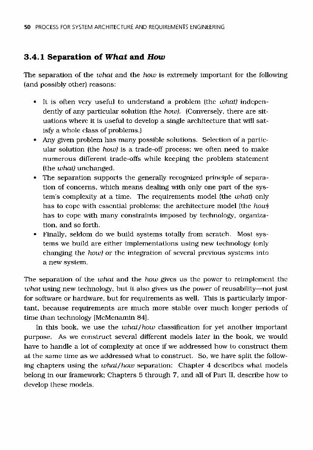
The separation of the what and the how gives us the power to reimplement thewhat using new technology, but it also gives us the power of reusability—not justfor software or hardware, but for requirements as well. This is particularly impor-tant, because requirements are much more stable over much longer periods oftime than technology [McMenamin 84].
In this book, we use the what /how classification for yet another importantpurpose. As we construct several different models later in the book, we wouldhave to handle a lot of complexity at once if we addressed how to construct themat the same time as we addressed what to construct. So, we have split the follow-ing chapters using the what/how separation: Chapter 4 describes what modelsbelong in our framework; Chapters 5 through 7, and all of Part II, describe how todevelop these models.

3: A FRAMEWORK FOR MODELING SYSTEMS 51
As mentioned, Chapters 5 through 7 describe the how of constructing themodels, but in Part II, we describe the how of applying these models to some realsystems—from that perspective, Chapters 5 through 7 represent the what! Thisis analogous to the layered structure of systems, in which architectural or designdecisions in one layer result in requirements in the layer below. This same princi-ple applies to this book, which itself is a kind of system.
The purpose of Part II and of the on-line model is to exemplify what real proj-ects must do—the what, the how, and also the when. The when refers to projectplanning and scheduling, including such issues as which tasks are conductedconcurrently, and which sequentially. Throughout the 1970's and 1980's, sim-plistic process models like the waterfall model predominated. We know now thatthere are no simple solutions to project planning and scheduling. Rather, theseare decisions that must be made for each project, by project management. It isthe manager's job to observe the process, to watch and interpret the results ofindividual steps, to take into account many constraints, and based on all of that,to reconfigure dynamically the what, the how, and the when of the project.
3.4.2 The Architecture Template
Our modeling framework employs an extension of the what /how split to classifysystems, subsystems, their components, and their activities according to ageneric architecture template. Figure 3.8 shows that this architecture templateclassifies a system or subsystem into five categories:
Figure 3.8: The Architecture Template.
1. The center region contains the main functions of the system: the corefunctional processing. Here, we model things that the systemabsolutely has to do, things that belong to the essence of the system,independent of any technology.
52 PROCESS FOR SYSTEM ARCHITECTURE AND REQUIREMENTS ENGINEERING
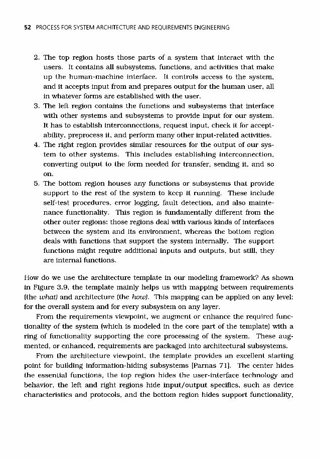
2. The top region hosts those parts of a system that interact with theusers. It contains all subsystems, functions, and activities that makeup the human-machine interface. It controls access to the system,and it accepts input from and prepares output for the human user, allin whatever forms are established with the user.
3. The left region contains the functions and subsystems that interfacewith other systems and subsystems to provide input for our system.It has to establish interconnections, request input, check it for accept-ability, preprocess it, and perform many other input-related activities.
4. The right region provides similar resources for the output of our sys-tem to other systems. This includes establishing interconnection,converting output to the form needed for transfer, sending it, and soon.
5. The bottom region houses any functions or subsystems that providesupport to the rest of the system to keep it running. These includeself-test procedures, error logging, fault detection, and also mainte-nance functionality. This region is fundamentally different from theother outer regions: those regions deal with various kinds of interfacesbetween the system and its environment, whereas the bottom regiondeals with functions that support the system internally. The supportfunctions might require additional inputs and outputs, but still, theyare internal functions.
How do we use the architecture template in our modeling framework? As shownin Figure 3.9, the template mainly helps us with mapping between requirements(the what) and architecture (the how). This mapping can be applied on any level:for the overall system and for every subsystem on any layer.
From the requirements viewpoint, we augment or enhance the required func-tionality of the system (which is modeled in the core part of the template) with aring of functionality supporting the core processing of the system. These aug-mented, or enhanced, requirements are packaged into architectural subsystems.
From the architecture viewpoint, the template provides an excellent startingpoint for building information-hiding subsystems [Parnas 71]. The center hidesthe essential functions, the top region hides the user-interface technology andbehavior, the left and right regions hide input/output specifics, such as devicecharacteristics and protocols, and the bottom region hides support functionality,

3: A FRAMEWORK FOR MODELING SYSTEMS 53
such as service and maintenance modules, and many more. An alternative namefor the template might be the information-hiding template.
Once we establish the functionality of the system and subsystems, we caneasily categorize and extract the core requirements for future reuse.
Figure 3.9: The Template Bridging Requirements andArchitecture Models.
3.4.3 Using the Architecture Template
In this section, we present two examples of using the architecture template toclassify the functionality of systems. To demonstrate that it can be used on anylayer of a system hierarchy and for any kind of application (automated or not), westart with an organizational system composed of automated and manual parts.
The template in Figure 3.10 illustrates the activities that are performed bynurses at their station in a hospital. We can divide the activities into the five cat-egories. By doing so, if the procedures for helping visitors (in the user-interfacepart of the template) are changed, the rest of the system can remain unchanged.The same is true for changing the policy for checking stock supplies in the main-tenance region, and for any changes involving just a single region of the template.

54 PROCESS FOR SYSTEM ARCHITECTURE AND REQUIREMENTS ENGINEERING
Figure 3.10: Classification of Activities in a Manual System.
This nurses' station is a subsystem of an overall hospital system, for which wecould also classify the activities. Depending on the purpose of the whole hospitalmodel, the nurses' station would be part of the system core or may be consideredpart of the maintenance subsystem (to support the doctors).
The second example is of an automated system. Using the hospital applica-tion, we show how to classify the automated activities of a patient-monitoring sys-tem in Figure 3.11.
The architecture template is a very powerful modeling tool that we use repeat-edly to classify system or subsystem activities. Not only can it be used to bridgethe requirements/architecture models, it can be used very early in a project,before we even know the requirements or make decisions on the architecture, todiscover topics to be treated in more detail later. It can also be used in distribut-ing work among project members, allowing them to work concurrently.
USERINTERFACE
• HELP VISITORS• GUIDE PATIENTS TO DOCTORS' OFFICES• ANSWER PHONE CALLS• RESPOND TO PATIENT EMERGENCY CALLS
MAIN FUNCTION
• MONITOR PATIENT HEALTH• DISPENSE PRESCRIBED MEDICATIONS• ADMINISTER ROUTINE TESTS• KEEP PATIENT HEALTH RECORDS• KEEP PATIENT BILLING RECORDS• ASSIST DOCTOR ON ROUNDS
OUTPUTPROCESSING
• CHECK OUTPATIENTS
•ISSUE ALERTS TODOCTORS ANDSTAFF
• FILE REPORTS•ORDER SUPPLIES• SEND PATIENT
BILLING TOACCOUNTINGDEPARTMENT
SUPPORT
• MONITOR DESK OPERATIONS• CHECK NURSES' SCHEDULES• CHECK STOCK SUPPLIES
INPUTPROCESSING
•CHECK IN PATIENTS• SCHEDULE PATIENT
MONITORING• RECEIVE AND LOG
INCOMINGMEDICATION
• RECEIVE SUPPLIES

3: A FRAMEWORK FOR MODELING SYSTEMS 55
USER • GET NURSE ENTRIESINTERFACE •VALIDATE NURSE ENTRIES
• DISPLAY ALERTS• FORMAT AND DISPLAY PATIENT-MONITORING STATUS
INPUTPROCESSING
• MEASURE PATIENTVITAL SIGNS
• MEASURE PATIENTMOTION
•VALIDATE VITALSIGN SENSORREADINGS
• ISSUE EQUIPMENTFAILURE ALERT
MAIN FUNCTION
• SET UP SCHEDULE FOR MONITORING• FIND UNSAFE VITAL SIGN RANGE FOR
PATIENTS• COLLECT DATA FOR PATIENT• PERFORM ANALYSIS FOR SELECTED
PATIENT•ISSUE PATIENT ALERT
SUPPORT• UPDATE PATIENT SAFE RANGES• UPDATE EQUIPMENT OPERATING
RANGES
OUTPUTPROCESSING
• PRINT REPORT
Figure 3.11: Classification of Activities in an AutomatedSystem.
3.5 EXPLOITING THE INFORMATION/MATERIAL/ENERGYCLASSIFICATION
The final step in constructing our modeling framework is to classify systemsaccording to their information, material, and energy processing characteristicsthat we discussed in Section 2.2.1.
3.5.1 A Generic Subsystem Structure
In Chapter 2, we showed that everything a system does can be classified intomaterial processing, energy processing, and information processing. Since mater-ial and energy processing are quite different from information processing, we cantreat these two areas separately. If we combine this decision with the idea of cate-gorization provided by the architecture template, we end up with the system parti-tioning shown in Figure 3.12, which divides the processing into finer classifica-tions. These finer classifications become subsystems of the overall system. AsFigure 3.12 shows, there are subsystems that do the two different types of pro-cessing, but the overall, or boundary, subsystem does both. Figure 3.13 explainsmore about the functions of the various subsystems.

56 PROCESS FOR SYSTEM ARCHITECTURE AND REQUIREMENTS ENGINEERING
Figure 3.12: Separating Material/Energy Processing fromInformation Processing.
Note that there is no box in material/energy processing equivalent to the deciderin information processing. With today's systems, the decision-making function isalmost always an information processing function. Consequently, Figures 3.13through 3.16 all have a blank entry in the material/energy processing side.

3: A FRAMEWORK FOR MODELING SYSTEMS 57
Boundary:Subsystem(s) that form a barrier around a system, shielding it from its environment.
InformationProcessing Subsystems
User Interface:Subsystem(s) to allow informationexchange with external human users.
Input Decoder:Subsystem(s) to convert the coding ofexternal information for internal use.
Functional Transformer:Subsystem(s) to transform inputinformation into output information.
Memory:Subsystem(s) to retain for later useinformation, its relationships, and itsorganization.
Decider:Subsystem(s) to control (for example,enable, inhibit, or trigger) functionaltransformers.
Output Encoder:Subsystem(s) to convert the coding ofinternal information for external use.
Support:Subsystem(s) to support systemmonitoring, servicing, andreconfiguration .
Material/EnergyProcessing Subsystems
User Interface:Subsystem(s) to allow material/energyexchange with external human users.
Input Converter:Subsystem(s) to transformmaterial/energy from external to internalforms.
Material/Energy Transformer:Subsystem(s) to transform and associatematerial/energy inputs to outputs.
Material/Energy Storage:Subsystem(s) to store material/energy forlater use.
Output Converter:Subsystem(s) to transformmaterial/ energy from internal to externalforms.
Supporter:Subsystem(s) to enable maintenance,growth, and reconfiguration.
Figure 3.13: Generic Description of Subsystem Responsibilities.
3.5.2 Categories of a Deliverable System
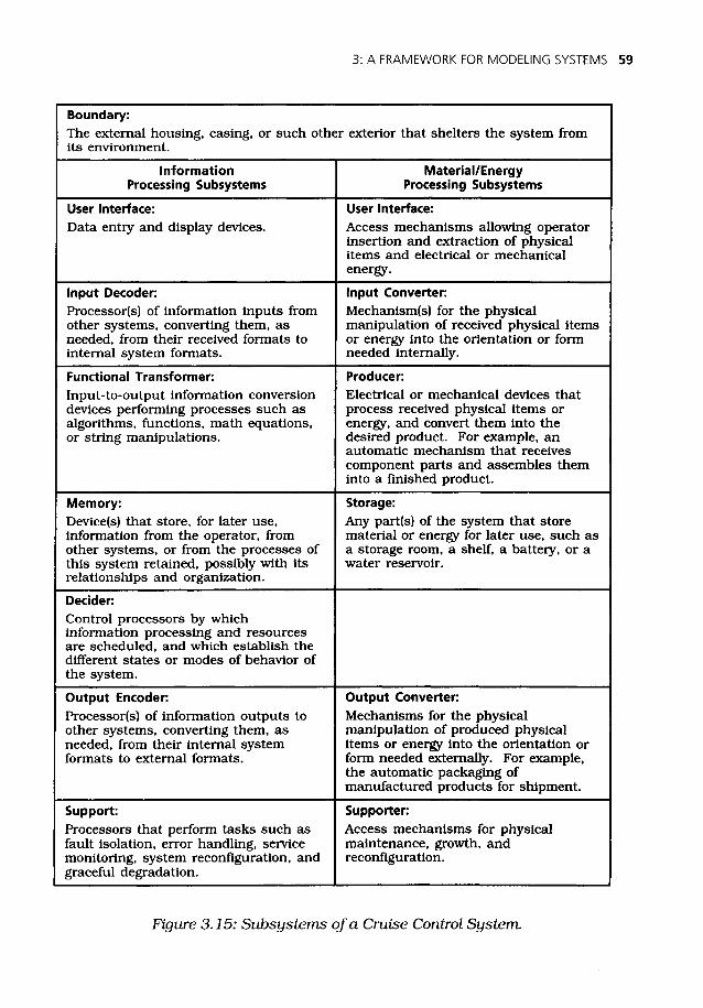
For a deliverable system, product, or component, the categorization scheme intro-duced above can be a useful starting point for brainstorming the subsystems.Figure 3.14 makes the generic categories of Figure 3.13 specific to all deliverablesystems, and Figure 3.15 makes them specific to a cruise control system.
Note that the categories in the generic template are applicable to many sys-tems, although there are usually some that are not applicable to a specific sys-tem. Consider the generic categories a pattern for thinking about a system andits subsystems.

58 PROCESS FOR SYSTEM ARCHITECTURE AND REQUIREMENTS ENGINEERING
Boundary:The external housing, casing, or such other exterior that shelters the system fromits environment.
InformationProcessing Subsystems
Material/EnergyProcessing Subsystems
User Interface:Data entry and display devices.
User Interface:Access mechanisms allowing operatorinsertion and extraction of physicalitems and electrical or mechanicalenergy.
Input Decoder:Processor(s) of information inputs fromother systems, converting them, asneeded, from their received formats tointernal system formats.
Input Converter:Mechanism(s) for the physicalmanipulation of received physical itemsor energy into the orientation or formneeded internally.
Functional Transformer:Input-to-output information conversiondevices performing processes such asalgorithms, functions, math equations,or string manipulations.
Producer:Electrical or mechanical devices thatprocess received physical items orenergy, and convert them into thedesired product. For example, anautomatic mechanism that receivescomponent parts and assembles theminto a finished product.
Memory:Device(s) that store, for later use,information from the operator, fromother systems, or from the processes ofthis system retained, possibly with itsrelationships and organization.
Storage:Any part(s) of the system that storematerial or energy for later use, such asa storage room, a shelf, a battery, or awater reservoir.
Decider:Control processors by whichinformation processing and resourcesare scheduled, and which establish thedifferent states or modes of behavior ofthe system.
Output Encoder:Processor(s) of information outputs toother systems, converting them, asneeded, from their internal systemformats to external formats.
Output Converter:Mechanisms for the physicalmanipulation of produced physicalitems or energy into the orientation orform needed externally. For example,the automatic packaging ofmanufactured products for shipment.
Support:Processors that perform tasks such asfault isolation, error handling, servicemonitoring, system reconfiguration, andgraceful degradation.
Supporter:Access mechanisms for physicalmaintenance, growth, andreconfiguration.
Figure 3.14: A Template for Subsystems of a Deliverable,Human-Operated System.
3: A FRAMEWORK FOR MODELING SYSTEMS 59
Boundary:
The external housing, casing, or such other exterior that shelters the system fromits environment.
InformationProcessing Subsystems
Material/EnergyProcessing Subsystems
User Interface:
Data entry and display devices.User Interface:
Access mechanisms allowing operatorinsertion and extraction of physicalitems and electrical or mechanicalenergy.
Input Decoder:
Processor(s) of information inputs fromother systems, converting them, asneeded, from their received formats tointernal system formats.
Input Converter:
Mechanism(s) for the physicalmanipulation of received physical itemsor energy into the orientation or formneeded internally.
Functional Transformer:
Input-to-output information conversiondevices performing processes such asalgorithms, functions, math equations,or string manipulations.
Producer:
Electrical or mechanical devices thatprocess received physical items orenergy, and convert them into thedesired product. For example, anautomatic mechanism that receivescomponent parts and assembles theminto a finished product.
Memory:
Device(s) that store, for later use,information from the operator, fromother systems, or from the processes ofthis system retained, possibly with itsrelationships and organization.
Storage:
Any part(s) of the system that storematerial or energy for later use, such asa storage room, a shelf, a battery, or awater reservoir.
Decider:
Control processors by whichinformation processing and resourcesare scheduled, and which establish thedifferent states or modes of behavior ofthe system.
Output Encoder:
Processor(s) of information outputs toother systems, converting them, asneeded, from their internal systemformats to external formats.
Output Converter:
Mechanisms for the physicalmanipulation of produced physicalitems or energy into the orientation orform needed externally. For example,the automatic packaging ofmanufactured products for shipment.
Support:
Processors that perform tasks such asfault isolation, error handling, servicemonitoring, system reconfiguration, andgraceful degradation.
Supporter:
Access mechanisms for physicalmaintenance, growth, andreconfiguration.
Figure 3.15: Subsystems of a Cruise Control System.
60 PROCESS FOR SYSTEM ARCHITECTURE AND REQUIREMENTS ENGINEERING
3.5.3 Categories of a People System
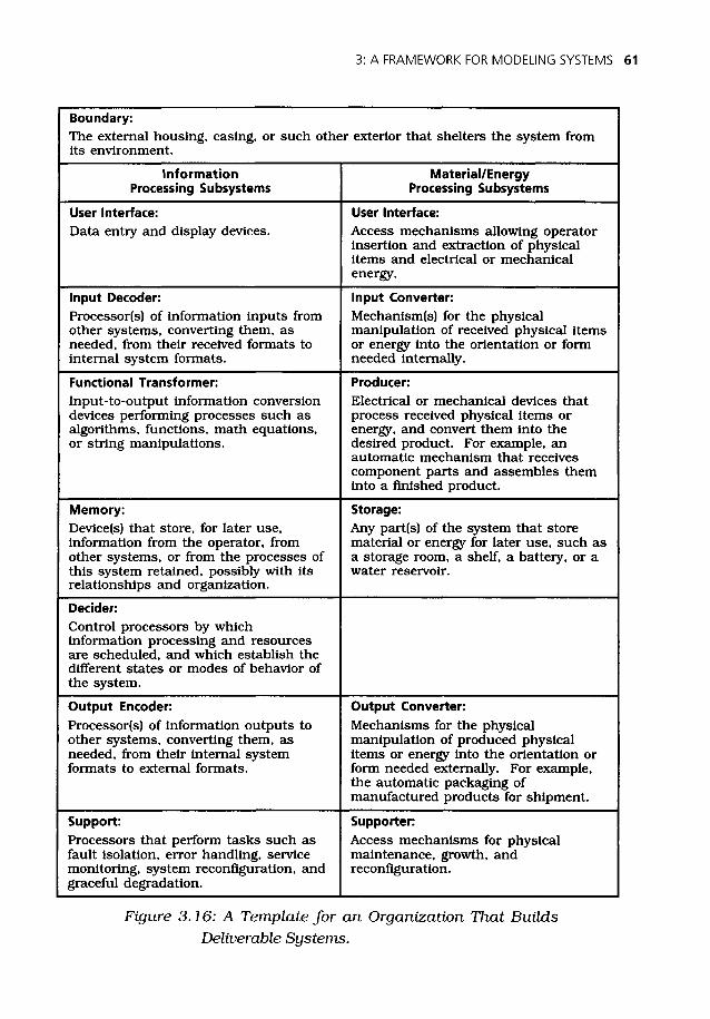
The systems we build reflect the organizations that build them. With this inmind, we can devise a categorization of organizational systems, such as of wholecompanies, departments, or groups of people cooperating to achieve a certaingoal. Figure 3.16 maps the generic categories onto an organizational structuredescribing the various subsystems in such a context. Figure 3.17 shows cate-gories specific to a garment factory. This kind of categorization helps to distin-guish between value-adding functions and overhead functions in an organization:It can be used as a starting point for modeling business processes and identifyingessential parts of them.
3.6 LAYERED MODELS: THE TRUTH AT LAST!
We discussed numerous characteristics and features of models in the previoussections, but we kept the important issue of layered models for the end of thischapter. In any discussion of systems, models of systems, or the process of build-ing systems, the term "layer" plays an important role. Here, we explore severalunique aspects of layers, and of the different relationships between layers,between elements in one layer, and between elements in different layers.
One purpose of this section is to dispel a couple of myths. First, there is themyth that all layered models fall into the category of functional decomposition or,worse yet, top-down functional decomposition. And second, that layered modelsare fundamentally incompatible with object orientation.
In the first pages of Strategies for Real-Time System Specification, we intro-duced a diagram titled, "The Total System Life Cycle," little realizing at the timejust how significant it was. It showed various layers of the system modelingprocess and layers of specifications resulting from that process. We elaborate onthat diagram in Figure 5.1 of this book, but for now, we discuss some of its impli-cations. What we have realized since creating that diagram is that there istremendous similarity between systems, system models, and the system develop-ment process. Layers are an important part of these similarities, but they are alsothe source of some confusion. There is not just one kind of relationship betweenlayers or elements of layers: We can identify several basic relationships that keeprecurring in different systems, system models, and in the development process.
3: A FRAMEWORK FOR MODELING SYSTEMS 61
Boundary:The external housing, casing, or such other exterior that shelters the system fromits environment.
InformationProcessing Subsystems
Material/EnergyProcessing Subsystems
User Interface:Data entry and display devices.
User Interface:Access mechanisms allowing operatorinsertion and extraction of physicalitems and electrical or mechanicalenergy.
Input Decoder:Processor(s) of information inputs fromother systems, converting them, asneeded, from their received formats tointernal system formats.
Input Converter:Mechanism(s) for the physicalmanipulation of received physical itemsor energy into the orientation or formneeded internally.
Functional Transformer:Input-to-output information conversiondevices performing processes such asalgorithms, functions, math equations,or string manipulations.
Producer:Electrical or mechanical devices thatprocess received physical items orenergy, and convert them into thedesired product. For example, anautomatic mechanism that receivescomponent parts and assembles theminto a finished product.
Memory:Device(s) that store, for later use,information from the operator, fromother systems, or from the processes ofthis system retained, possibly with itsrelationships and organization.
Storage:Any part(s) of the system that storematerial or energy for later use, such asa storage room, a shelf, a battery, or awater reservoir.
Decider:Control processors by whichinformation processing and resourcesare scheduled, and which establish thedifferent states or modes of behavior ofthe system.
Output Encoder:Processor(s) of information outputs toother systems, converting them, asneeded, from their internal systemformats to external formats.
Output Converter:Mechanisms for the physicalmanipulation of produced physicalitems or energy into the orientation orform needed externally. For example,the automatic packaging ofmanufactured products for shipment.
Support:Processors that perform tasks such asfault isolation, error handling, servicemonitoring, system reconfiguration, andgraceful degradation.
Supporter:Access mechanisms for physicalmaintenance, growth, andreconfiguration.
Figure 3.16: A Template for an Organization That BuildsDeliverable Systems.

62 PROCESS FOR SYSTEM ARCHITECTURE AND REQUIREMENTS ENGINEERING
Boundary:The building(s) that house the garment factory and its offices.
InformationProcessing Subsystems
Material/EnergyProcessing Subsystems
User Interface:People who negotiate the designs andcontracts with customers.
User Interface:Direct factory sales outlet, returnsdepartment.
Input Decoder:Purchase order processing, inventoryingof received materials.
Input Converter:People unpacking received materials,repackaging them in a form thatsupports the production process;people from personnel departmentscreening new hires.
Functional Transformer:Design department and equipment thattransforms customer requests intoactual designs to be manufactured.
Producer:Production line personnel andequipment that convert the receivedmaterials into finished garmentsaccording to the selected designs.
Memory:Storage of the designs, accountingrecords, shipping records, the employeerecords, and so on.
Storage:Supply cabinets, storage lockers, stockroom, and so on.
Decider:Management that determines theproduction schedules, the factory plans,and the coordination of the factory floor.
Output Encoder:People responsible for invoicing thecustomers, for waste disposalcoordination, and so on.
Output Converter:The shipping department, delivery truckdrivers, and so on.
Support:Customer accounting, payrolldepartment, and so on.
Supporter:The facilities and maintenance crewswho remove trash and keep the factoryin operating condition.
Figure 3.17: Subsystems of a Garment Factory.

3: A FRAMEWORK FOR MODELING SYSTEMS 63
Systems, models of systems, and the system development process share thefollowing attributes:
• They are layered.• The layers—once they are identified—form a structure that can be
read and interpreted in any sequence: from the top layers to the lowerlayers, from right to left, from bottom to top, and so on. Moreover, thelayers can be developed in any sequence: top to bottom, right to left,bottom to top, and so on, and the interpretation and developmentsequences are quite independent of each other.
• The number of elements per layer typically increases downward, giv-ing the whole structure a pyramidal shape; but note that we some-times have an independent structure of elements within one of themain layers. For such a structure, the basic statement of this para-graph is still true: The number of elements tends to increase down-ward.
• The elements forming the layered structure can be considered a set,either of activities or of entities. In any particular system, systemmodel, or development project, these elements may be carried out orused in some prescribed sequence, concurrently, or in any combina-tion of sequence and concurrency.
• Elements in the layers usually communicate and cooperate up, down,and sideways within and between layers. Communication and coop-eration can be in the form of information, material, or energy, depend-ing on the kind of system, model, or process in question. Some earliermodels restricted the development process by asserting, for example,that all information flows vertically through the top layer, and thatonly information (not material or energy) can be communicated withthe outside world. However, our model recognizes that information,material, and energy can all flow sideways to and from individual lay-ers, and can all interact with the outside world.
• Every layer includes, deals with, or is associated with, some require-ments, some architecture or design, some construction or implemen-tation, and some integration and testing. Also, each layer usuallyrequires planning, quality assurance, management, and other items,but we are not addressing these in this book.

64 PROCESS FOR SYSTEM ARCHITECTURE AND REQUIREMENTS ENGINEERING
An important conclusion for us is that layered models—for systems or as meta-models for system development processes—do not inherently imply any particularsequence. They represent a static structure (of a system, its development, thedevelopment process, or models of any and all of these) that can be populated inany convenient sequence that makes sense for the problem at hand. This pointwas beautifully made by Parnas—arguably the father of information-hiding struc-tures—in [Parnas 86].
So, the layers and the elements in layers are nondirectional, but we are inter-ested in their relationships. There are probably many types of relationships in lay-ered models, but four of them are of special interest in system development:aggregation/decomposition, abstraction/detailing, supertype/subtype, and con-trolling/controlled. Let us look at each of these in detail, discussing properties oftheir relationships and examples from our methods and other well-knownapproaches.
3.6.1 Aggregation/Decomposition Relationship in Models
The architecture model, resulting from the architecture method, is an example ofan aggregation/decomposition model. Such models characterize real physical ele-ments, their sub-elements or parts, and their super-elements or assemblies. Ele-ments in the higher layers actually consist of the elements in the lower layers, orconversely, elements in the lower layers are decompositions of those in the higherlayers. The structure is also known as a whole/part structure [Coad 91] or a con-tainer/content structure: A given layer provides the container for the layer below,which is the content of the layer above. In entity-relationship modeling, entitiescan be linked by composed-of or consists-of relationships. In manufacturingterms, it is an assembly/subassembly/component structure. This type of struc-ture is pervasive in engineering and in everyday life.
An aggregate actually involves more than just collecting sub-elements into aset. The sub-elements must also interface with each other, requiring linkagesbetween them that may not be evident when they are considered separately. Thisis why we discuss enhancement of abstract requirements, using the architecturetemplate, in our methods when the requirements are mapped into real physicalmodules.
We can better imagine aggregation/decomposition structures applied at thesystem levels, where physical hardware of various kinds is involved. For software,which does not have a physical form, it is not so clear. The trick is to imagine

3: A FRAMEWORK FOR MODELING SYSTEMS 65
that software does have a physical form. A complete software program or assem-bly can be considered as an architecture module at the highest software layer;major subprograms it contains are modules in the next layer down; sub-subpro-grams or subroutines (if any) form a further layer, and so on. As we discuss else-where in this book, a transition can be made from an aggregation/decompositionmodel to an object-oriented representation by defining modules to be aggregateobjects, as described, for example, in [Page-Jones 95, Section 4.2]. Once in theobject-oriented domain, other structures may apply, depending on the particularobject-oriented approach used.
To summarize the usage of this relationship: We build layers to show physicalpackaging of elements into larger groups or assemblies. In each layer, we candefine physical interfaces between elements or between groups. The groupingforms a sort of fence around its elements, potentially protecting the visibility ofthe interior elements or regulating the access to them. In software development,we use terms like information hiding, scope, and visibility control to describe thenature of the aggregation/decomposition relationship.
3.6.2 Abstraction/Detailing Relationship in Models
When we use an abstraction/detailing relationship in models, the higher layersare simply more abstract expressions of the lower layers, or conversely, the lowerlayers are more detailed expressions of the higher layers. The most familiarexample of this relationship occurs in Structured Analysis (SA), usually repre-sented by data flow diagrams. (Note that the control model of the real-time exten-sions of SA does not use this relationship—see Section 3.6.4.) The process modelpart of the requirements model, being founded on SA, uses the abstraction/detail-ing relationship for processes and their child diagrams. In a sense, the wholerequirements model—if applied correctly—is abstract throughout because it con-sists only of narrative statements (albeit in structured form) that do not necessar-ily correspond to real physical groupings of processes, entities, or control struc-tures.
The abstraction/detailing relationship often has been erroneously namedabstraction/decomposition. Although we, too, have been guilty of using this ter-minology, we now disagree with it. First, abstraction and decomposition are notopposites, and the essence of these relationship name pairs is that they should beopposites, reflecting the upward and downward viewpoints in a layered model.Second, decomposition is the opposite of aggregation, which is why we use it in

66 PROCESS FOR SYSTEM ARCHITECTURE AND REQUIREMENTS ENGINEERING
the aggregation/decomposition relationship described above, where something isbroken into the elements it contains. Consider this: An abstract requirementstatement does not contain the more detailed requirements statements thatdescribe it; however, a physical system element does contain the separable sub-elements of which it is an aggregate. If we take the elements of a physical systemand assemble them, we get the physical system; if we assemble a set of detailedrequirements, we merely have a collection of detailed requirements—the abstractand detailed requirements exist independently of each other, with an abstrac-tion/detailing relationship between them.
Our categorizations of layered structures, then, have led us to an interestingparadox. The terms to which we objected earlier—functional decomposition andtop-down functional decomposition—are frequently applied to Structured Analysisand its data flow diagrams, yet data flow diagrams, when used correctly to repre-sent abstract requirements, do not involve decomposition at all: They involvedetailing. When we use Structured Analysis to create essential models accordingto our own guidelines and those in [McMenamin 84] and [Robertson 98], we arenot decomposing downward through the layers; we are adding detail. Goingupward, we are not packaging or aggregating; we are abstracting.
Of course, if you are misusing SA to represent the aggregation and decomposi-tion of physical structures, then anything goes, and we cannot take responsibilityfor the results (which are usually awful).
How do detailing of the required capabilities and decomposition of the physi-cal structure relate to each other? As a system is developed, they proceed in par-allel, with sufficient detail added to the required capabilities to satisfy the needs ofa particular physical layer. This point is illustrated further in Part II.
3.6.3 Supertype/Subtype Relationship in Models
In the supertype/subtype relationship, an element in the higher layer—the super-type—includes all of the features that are common to its associated elements in thelower layer—its subtypes. These features—in the simplest case—are attributes (asthey are called in information modeling) that are inherited by the elements on thelower layer. Starting from the lower level, supertypes are formed for sets of ele-ments that share common attributes. Thus, we might have at the top level "vehi-cle," and at the level below "ship," "aircraft," and "land vehicle." Below "land vehi-cle," we might have "bicycle," "motorcycle," "ATV," and "automobile." This tells us,for example, that an automobile is a land vehicle and a land vehicle is a vehicle.
3: A FRAMEWORK FOR MODELING SYSTEMS 67
Supertype/subtype models are important in object orientation. This relation-ship is the foundation for inheritance—one of the essential and most powerful fea-tures of object orientation. Attributes of "vehicle," in the above example, areinherited by all the other elements, and attributes of "land vehicle" are inheritedby all of the elements in its subtypes. Object orientation has taken this relation-ship and extended it to more complex forms of inheritance than just attributeinheritance: The lower layer may also inherit functions (or operations, or "meth-ods," as they are sometimes called) and the behavior of the supertypes.
Supertype/sub type relationships are also referred to as generalization/spe-cialization relationships, class hierarchies, inheritance structures, and "is-a" hier-archies. With the supertype/subtype relationship, it is important that the super-type contains all the commonalities of the subtypes. The main use of this rela-tionship is to discover commonalities and to describe them only once, thus reduc-ing redundancy. The structure then allows the lower layers to inherit whatevercommonalities have been discovered.
Now that we have defined the supertype/subtype relationship, we can see thatthe relationship is, in fact, a subtype of the abstraction/detailing relationship. Asupertype is an abstraction of its subtypes, and the subtypes are detailedinstances of the supertype. So, all supertype/subtype relationships are alsoabstraction/detailing relationships, but the converse is not true: Not all abstrac-tion/detailing relationships are supertype/subtype relationships, because not allabstraction/detailing relationships follow the "is-a" principle. For example, aprocess on a data flow diagram and its child diagram are an abstraction/detailingpair, but it is not true that a child diagram "is-a" parent process.
3.6.4 Controlling/Controlled Relationship in Models
This relationship distinguishes between up and down by having the upper layerscontrol elements of the lower layers. Other terms used for this relationship arethe control hierarchy, or the is-boss-of/is-supervised-by relationship. Sometimes,we simply say that the higher element uses the lower elements. The higher layermust have knowledge of the lower layer but the lower layer—that is, the one beingused—does not necessarily have to know anything about the boss. In terms ofclient/server models, the client is the boss that delegates work to the server; theserver provides certain services that are performed whenever a client asks forthem.

68 PROCESS FOR SYSTEM ARCHITECTURE AND REQUIREMENTS ENGINEERING
In the requirements method, the control model controls processes in theprocess model, by activating or deactivating them. In the architecture method, wecan model client/server behavior to avoid iterative cycles between architecturemodules.
Structured Design, the software design method, provides another example of acontrolling/controlled relationship. In its main graphical model, the structurechart, a given module invokes (that is, it uses, calls, or controls the execution of)modules in the layer below. Structured Design is one of several methods that canbe used in conjunction with the requirements and architecture methods, asdescribed in Strategies for Real-Time System Specification, Section 24.3, and inChapter 4 of this book.
3.6.5 Layered Models Summary
We hope we have succeeded in dispelling the myth that all layered models arebuilt top-down using decomposition, and have shown that this simplistic, one-size-fits-all view of these models is wrong. The four types of relationships in lay-ered models, described above, are distinctly different from each other; they allserve distinct and important roles in system development; and they can be inte-grated smoothly, where appropriate, with other models, including object-orientedmodels. Figure 3.18 summarizes the key aspects of the four relationships in andbetween layers or their elements.
Even though the four relationships are different, it is convenient to have atleast one terminology that can be used with all of them. For this purpose, the"family tree" relationship analogy—of parent/child, grandparent/grandchild, andancestor/descendant—is commonly used. Although close inspection shows thatthe analogy does not really fit all four of the relationships (for example, childrenare not decompositions of their parents), these terms sufficiently describeabove/below relationships.
We can now enlarge on the statements of Section 2.1.3 "Multiple Hierarchies."The four layered models we have described can be—and frequently are—usedsimultaneously to represent different aspects of one system. Using the require-ments and architecture methods, the required functional capabilities of a systemare captured by the process model—an abstraction/detailing model; the requiredbehavioral capabilities are captured by the control model—a controlling/con-trolled model; information structures in the system might include supertype/sub-type relationships, captured in an entity-relationship model; and the physical

3: A FRAMEWORK FOR MODELING SYSTEMS 69
Aliases
DownwardUsage
UpwardUsage
Where Used,Roles
Purpose ofUsage
Aggregation/Decomposition
Whole/part;container/content;composed-of;consists-of;assembly/subassembly/component
Decompose;dismantle
Aggregate;assemble
Architecturemodel;objectorientation(aggregateobjects);requirements andarchitecturedictionaries
Physical packaging;information-hiding;defining scope andvisibility
Abstraction/Detailing
(Erroneously:abstraction/decomposition)
Add detail;specialize
Make abstract;generalize
Requirementsmodel;StructuredAnalysis; nestingin statecharts
Coping withcomplexity;reducingcomplexity
Supertype/Subtype
Generalization/specialization;class hierarchy;inheritancestructure;"is-a" hierarchy
Inherit;specialize
Set membership;"is-a";generalize;categorize
Architecture modelwhen used withobjectorientation;entity-relationship-attributemodeling
Similar toabstraction/detailing;in addition:inheritance ofattributes,functions, behavior
Controlling/Controlled
Is-boss-of/is-supervised-by;useshierarchy;client /server
Control
Controlledby
Controlmodel (ofrequirementsmodel);StructuredDesign;systemcontrolstructures(occurswithin alayer as wellas betweenlayers)
Separationof concerns;creatingnoncyclicclient/serverstructures;simplifyingcooperation
Figure 3.18: Summary of Relationships in Layered Models.
structure is captured by the architecture model—an aggregation/decompositionmodel. Thus, to model a single system, not only can we use layered models of thesame kind, as described in Section 2.1.3, we can also use layered models of differ-ent kinds. This allows us to represent different views of the system separately,but, when done as part of the requirements and architecture methods, the linksbetween these views are carefully maintained.
70 PROCESS FOR SYSTEM ARCHITECTURE AND REQUIREMENTS ENGINEERING
This highlights the great flexibility of layered models. They are extraordinarilyversatile, and allow us to represent just about any facet of systems and systemdevelopment separately and at any desired level of detail, but with the links to theother facets also represented.
3.7 MODEL FRAMEWORK SUMMARY
Our modeling framework, shown in Figure 3.19—which is derived from Fig-ure 3.7—now combines all the ideas described in this chapter. For most systems,especially larger ones, we exploit the idea that systems come in hierarchies. Wehave layers of specifications for the system, subsystems, sub-subsystem, and soon. But note that the flows between the layers go both ways—up and down.There is no sequence of development implied in this framework. We build groupsof models as we discover subsystems in the hierarchy, and we do so in any orderwe want.
Forming subsystems is a difficult architectural or design decision, butexploitation of the information/material/energy classifications and of the genericsubsystem categorization will guide us along the way. For software developers,we have many more guidelines in Chapter 6.
Each group of models separates the what from the how: We build separaterequirements and architecture models. To help with the transition between whatand how models, we build enhanced requirements models based on the architec-ture template. Thus, each group of models consists of three separate but relatedtypes: requirements, enhanced requirements, and architecture. Note that thearrows between the three models in the subsystems of Figure 3.19 go both ways—again, allowing these models to be developed in any sequence.
The information-hiding categories described in Section 3.6 are helpful forstructuring all three models. They are generic enough to be applicable in manydifferent application areas, yet precise enough to give a head start for partitioning.In many large applications, such subsystems have produced flexible, extendable,and maintainable systems. The case study in Part II demonstrates this idea witha specific example from a unique application domain.

3: A FRAMEWORK FOR MODELING SYSTEMS 71
Figure 3.19: The Modeling Framework.

This page intentionally left blank

Index
abstract interface module 261, 263-66abstraction/ detailing 65-66, 67, 92, 233,
272, 274, 402ACD See architecture context diagramAda-based Design Approach for Real-Time
Systems (ADARTS) 255, 402AFCD See architecture flow context dia-
gramAFD See architecture flow diagramaggregation 272, 402aggregation/ decomposition 64-65, 92, 93,
96, 99, 103, 106, 123, 233, 257,258, 402
rules and guidelines 123A/CD See architecture interconnect context
diagramAID See architecture interconnect diagramaircraft example 193, 1 94ATS See architecture interconnect specifica-
tionAMCD See architecture message context
diagramAMD See architecture message diagramAMS See architecture module specificationarchitect 200-204, 273, 402
architecture 226, 268-73, 348, 393, 403channel 204, 357, 393, 403communication model 92-103, 403context 286-87, 346context level 206, 222diagram 90-92, 107, 227, 403inheritance model 106-8interface 343level 393,400method 4, 7, 64, 179, 190-99, 200,
205, 244, 245, 250, 253, 257, 273,275, 389, 391, 396, 398, 400, 404
structure 274architecture context diagram (ACD) 75,
215, 222, 284, 288, 341-43, 391,392, 403
architecture dictionary (AD) 75, 80, 92,108-10, 111-12, 177, 197, 233,362, 376, 385-86, 388, 403
rules and guidelines 110architecture flow 79-82, 83, 84, 88, 94,
177, 206, 222, 223, 229, 239, 249,250, 357, 362, 373, 383, 388,393-94, 403
rules and guidelines 110
425

426 INDEX
architecture ftow context diagram (AFCD)75, 87, 88-89, 171-72, 222, 223,224, 284-85, 288, 241-42, 392,403
rules and guidelines 88-89architecture ftow diagram (AFD) 76, 91, 92,
94-96, 97, 98, 103, 108, 110, 111,172, 174, 228, 229-30, 238ff., 247,248, 254, 255, 258, 348, 363, 373,376-77, 380, 381,393
rules and guidelines 95-96architecture inheritance model 403architecture interconnect 86-87, 240, 249,
250, 362, 393, 403rules and guidelines 87
architecture interconnect context diagram(AICD) 75, 87, 88-90, 171, 223,225, 288, 341^3, 382, 392, 403
architecture interconnect diagram (AID) 76,103, 104-6, 110, 111, 229-30,238ff., 245-46, 247, 248, 258, 288,290, 362, 363, 373-74, 376, 378,381, 391-92,403
rules and guidelines 105-6architecture interconnect specification (AIS)
76, 106, 111, 239, 250, 382, 388,395, 403
rules and guidelines 106Architecture Level 1 Model 220-23,
224-27, 228, 229, 233architecture message context diagram
(AMCD) 75, 87, 89, 403architecture message diagram (AMD) 76,
89, 91-92, 97-98, 99-100, 103,110, 111,403
balancing 111-12hierarchy style 99-100network style 97-98
architecture model 64, 69, 72, 74-112,135, 136, 141, 142, 164, 167, 169,170, 177, 180, 190, 192, 194, 197,200, 206, 209, 224-27, 230,233-34, 257ff., 274, 276, 277,288-89, 304, 311, 315, 316, 318,334, 387-88, 391, 396, 398ff., 404
allocation of 224-27balancing 110-12
development 233requirements model and 170-78
architecture module 76, 77ff., 81, 83, 85,88, 92, 94ff., 103ff., 108, 112, 138,172, 174ff., 192, 194, 196, 198,224ff., 230, 233, 236, 247, 250,254, 256-57, 259-61, 264, 267-68,271, 274, 290, 315, 345, 347ff.,352, 357, 362, 366, 377, 382,387-88, 390, 395, 404
concurrent 376rules and guidelines 78
architecture module specification (AMS) 76,92, 101-2, 106, 110, 111-12, 126,198, 212, 230, 250, 252, 303, 375,378-82, 388, 395, 404
rules and guidelines 101-2architecture template 53-54, 88, 97, 99,
166-69, 171-72, 198, 220-21, 224,228, 257, 259, 261, 275, 276,291-95, 331, 393, 394, 404
customer specification 293hardware/ software 292hardware specification 295rules and guidelines 1 68-69software specification 295system integration 293system specification 295variations on 291-95
assembly / subassembly / component 193associative entity class 123-25
attributes and 123-25rules and guidelines 125
attribute 116, 123-25, 162, 164, 233, 267,308, 404
associative entity classes and 123-25rules and guidelines 116
automated tool 8, 183, 200, 212, 397, 404Axiom/ Sys 404, 423
balancing 1 77-78 , 404black box 186, 226, 244, 315, 404Boehm, Barry W. 184, 419Booch, Grady 85, 119, 178, 180, 256,
419,421Brooks, Frederick P., Jr. 256, 419bubtangle 78, 404

INDEX 427
buffer 221,263input and output 266output-processing 22 1support 262user interface 22 1
capability 315, 404Capability Maturity Model (CMM) 181, 404,
420cardinality See multiplicityCASE 3, 4, 164, 183, 254, 352, 389, 396,
399, 405case study 6, 7, 8, 171, 180CCD See control context diagramCFD See control Jlow diagramchannel 76, 198, 288, 342, 349, 362, 381,
405Chen, Peter 118,419child 405
diagram 65, 96, 98, 105, 138, 158,172, 174, 196, 221, 226, 227, 234,364-65, 393
model 236processes 233
child architecture Jlow diagram 234, 288child control Jlow diagram 158child DFD 138, 140, 142child process specification 140cZass diagram 28, 33, 73, 90-92, 115,
125-26, 128, 170, 281, 307-8,397, 405
rules and guidelines 126class model 270Clemens, Paul C. 399, 422client 277-78, 281, 405
requirements 278, 281, 284system 277-78
client/ server 274CMM See Capability Maturity ModelCoad, Peter 64, 256, 420COBOL 269CODARTS 255-56, 268, 405combinational machine 153-54, 405commercial off-the-shelf system (COTS)
252, 405component 162, 175, 234, 247, 259,
271-72, 278, 345, 405kinds of 278
composed-of 193Concurrent Design Approach for Real-Time
Systems (CODARTS) 255-56, 268,405
concurrentengineering 184, 187-90, 291, 405model 188-90process 268
consists of 143-44constraint 301-3
design 301-2input/ output 301other 303
content perspective 1 2context 12, 213, 215
control vs. 160-61diagram 87, 88, 96, 138, 285, 304-5,
406control 406
hierarchy 271layers 269mode* 68, 113-14, 139, 143-56, 166,
169, 170, 206, 233, 267-68, 395,398-99, 406
module 269process 161, 165, 168, 169, 406
control context diagram (CCD) 156-57,171-72, 406
rules and guidelines 157control/ data flow diagram (C/DFD) 172,
174, 352enhanced 172
control flow 106, 114, 129, 131, 144, 151,155-56, 157, 158, 159-60, 161,162, 164, 169, 399
input 153model 155-56output 153-54rules and guidelines 155-56sources for 144
control Jlow diagram (CFD) 131, 156-60,164, 166, 168, 221, 406
data condition 1 59rules and guidelines 1 59-1 60
controlling /controlled 64, 67-68, 93, 97,254, 258, 268-69, 271-72, 274,406
control specification (CSPEC) 101, 114,

428 INDEX
144, 146-47, 150, 154ff., 158,159-60, 161, 164, 166, 169, 174ff.,227, 233, 334, 352, 356, 388, 395,396, 406
bar 156, 158, 159-60, 174, 175, 407guide 175, 407
COTS 252, 405Crosby, Philip B. 36, 420CSPEC See control specificationcustomer 307-8, 342, 407
requirements 376, 387customer specification 210, 299-303, 305,
318, 322, 326, 331, 338, 341, 375,378, 380
for groundwater analysis system299-303
DARTS 255data 407
condition 160, 166, 169, 407control and 394-95flow 383, 399, 407information modeling and 24model 267, 395, 407
database management system (DBMS) 268data context diagram (DCD) 131, 135-37,
157, 171,407rules and guidelines 136-37
dataflow 83, 106, 129, 131-33, 137ff.,144, 150, 155, 157ff., 164, 169,249, 395, 399, 407
rules and guidelines 1 32-133dataflow diagram (DFD) 65, 110, 131,
137-39, 140, 159-60, 164, 166,168, 169, 216, 217, 218, 227, 230,233-35, 275, 278-80, 317-25,327-29, 334, 337-40, 352, 355-57,362, 364-67, 390, 395, 397, 407
definition of 137elements of 137-38rules and guidelines 138-39
dataflow model 155data process 165, 168data store 131, 164, 175, 270, 278, 407
splitting a 175DBMS 268DCD See data context diagramDDL 268
decision table (DT) 154, 158, 160, 268,408
DeMarco, Tom 130, 420Deming, W. Edwards 36, 420derived requirement 32, 141, 364, 391,
393, 408design 257, 301-2, 408Design Approach for Real-Time Systems
(DARTS) 255, 301-2, 408detailing diagrams 139-41
with child DFD 1 39^ 1u>ithPSPEC 139-41
development process 181, 183-90, 205,275, 277-78, 408
architecture 288-90concurrent development process
184-87evolution of 183-84model 278, 291PSARE 6, 181, 413task allocation 29 1
DFD See dataflow diagramdictionary See architecture dictionary,
requirements dictionarydomain 273, 288DT See decision tabledynamic allocation 177, 242-44, 408
EDFD See enhanced dataflow diagramEeles, Peter 271,420encapsulation 256-57Engineering of Computer-Based Systems
(ECBS) 244, 409enhanced control/data flow diagram
(EC /DFD) 172enhanced dataflow diagram (EDFD) 222,
233, 282-83, 284, 291, 332-33,335-36, 349-51, 357-62, 364,370-72,380-81,409
enhancementof models 221,277,281-84,288,290of requirements 206, 222, 224-25,
228, 343, 348, 388, 409of requirements model 166, 220-23,
225-26, 228, 233, 259, 275-76,289, 311-12, 315, 334, 342, 346,349-56, 387, 409
entity 233, 307-8, 409

INDEX 429
model 112-14, 119-29, 166-67, 169,170, 174, 180, 304, 307-11, 392
modeling 121, 124specification 308, 409
entity class 32, 33, 73, 116-18, 120, 121,123-24, 126, 127, 128, 129, 162,164, 409
rules and guidelines 118specification 126-27
environment 210, 212, 217, 222, 331,391,409
essential model 222, 271, 276, 284-85,290, 291, 312, 315, 316-30,331-40, 346, 409
enhancing the 33 1 -40essential requirements 166, 222, 289, 311,
357, 388event 160, 409Existing Sampling Module 311-15external stakeholders 285
feasibility analyses 202-3field programmable gate arrays (FPGA) 252flight management system 149-50flow 76, 81, 83-85, 88, 95, 100, 106, 109,
131, 132-33, 134-35, 136, 138,139, 153, 158, 161, 198, 212, 217,218, 222, 227, 229, 233, 240, 247,249, 257, 274, 288, 304, 311, 344,357, 362, 381, 394, 395, 410
controlled 144data 144input 144messages and 83-85output 144, 304stores and 131,212
flow diagram 106, 133, 177, 278, 410child architecture 96
Junction 254, 410functional primitive 1 39
Gomaa, Hassan 255, 420groundwater analysis system 6, 249, 250,
299-388, 391, 396Existing Sampling Module for 302,
304, 311-15, 343-16, 348, 364-66,379, 381, 387
Groundwater Specimen for 307-8, 311Sample Analyzer Module for 344^7,
348-49, 355, 358-59, 370-71,376-78, 379-80, 381, 387
hardware layers 251 -52hardware /software 236-14, 392
configuration 239, 241interfaces 239, 392partitioning 14
hardware technologies 244-51chemical 249electrical 245-16electromechanical 247electronic 247hardware design 250hydraulic 248-19manufacturing 250mechanical 248mixed technologies 250-51optical 249pneumatic 248-^9
Harel, David 147, 396, 420Hatley, Derek 3, 180, 420-21Hatley/Hruschka/Pirbhai methods (H/H/P)
6, 7, 136, 299, 315, 389, 401, 410Hatley /Pirbhai methods (H/P) 3, 5, 389,
410H/H/P methods See Hatley/Hrusch-
ka/Pirbhai methodshierarchy 46, 67, 410
aggregation/ decomposition 93, 99class 67control 269, 271controlling /controlled 93is-a 67networks and 90-92supertype/ subtype 107
hospital monitoring system 6H/P methods See Hatley / Pirbhai methodsHruschka, Peter 5, 422Humphrey, Watts 183
IEEE 244"-ilities" 303, 380implementation 267-68, 410INCOSE 410

430 INDEX
information hiding 256, 259, 262, 269module 261, 410
information /material /energy 55-60, 161,212, 257
information model 206, 233, 261, 410inheritance 76, 77, 86, 107, 256-57, 258,
268, 274, 410structure 274
inheritance relationship 85-86, 106, 107,108
rules and guidelines 86input and output
flows 82, 138processing 331
input processing 187, 410interconnect 87, 206, 212, 228, 230, 234,
245, 249, 250, 344, 382, 392,393-94, 395, 410
interface 236,277,288,315,331,410International Council on Systems Engineer-
ing (INCOSE) 410is-a relationship 121, 122,411
Jackson, Michael 255, 421Jackson System Development (JSD) 255Jacobson, Ivor 178, 180, 256, 271, 419, 421
layer 185-87,270-71,280-81,411application 269architectural 223control 269Deliverable System Development 186Implementation 185in model 60-70,411structure 205, 253in systems 46-47, 185Top System Element 1 86
Maier, Mark 18,421,422Manhattan Island example 27-28McConnell, Steve 16, 421McMenamin, Stephen 66, 112, 180, 421message 76, 79, 81-85, 97, 100, 256-57,
411definition of 81diagrams 98flows and 83-85
rules and guidelines 82message /call 98message specification 102-3, 111, 411
definition of 102-3meta-model 275-96,411method 178, 181-83, 200, 209, 250, 256,
389, 390,397-400,411See also Hatley/Hruschka/Pirbhai
method (H/H/P), Hatley / Pirbhaimethod (H/P)
process, tool, and 181-83MID 76, 106, 107-8, 110model 205-74, 275, 278, 280, 311, 344,
346-47, 393,411See also architecture model concurrent
model, control model, meta-modelrequirements model
abstraction/ detailing 68, 192, 197aggregation /decomposition 64, 69,
192-93, 197client /server 67context- level 210environment 212, 213, 217, 222essential 222layered 60-70,411requirements /architecture /design 191supertype/ subtype 67system specification 191-93,207
modeling elements 76-87See also architecture flow, architecture
interconnect, architecture model,Jlow, inheritance relationship, mes-sage, and terminator
module 87, 100, 106, 168, 212, 225, 233,247, 249, 254, 259, 268, 315, 344,347, 349, 357, 393, 396, 411
See also architecture moduleapplication 270control 269hardware 236hardware /software 237software 236, 240specification 376
module inheritance diagram (MID) 76, 106,107-8, 110,411
rules and guidelines 108multiple architecture models 174-75

INDEX 431
multiple hierarchies 9multiple inheritance 107multiplicity 119-20, 121, 124, 128, 305,
308, 412
Naval Research Laboratory's Software CostReduction Method 255
networks 90-92
object orientation (OO) 67, 94, 178-79,256-58, 268, 271, 391, 392, 399,412
architecture and 272constructs of 391methods of 178-79, 257, 271
object-oriented design (OOD) 255, 256-57,412
output processing 221, 276, 412
Page-Jones, Meilir 86, 254, 255, 258, 421Palmer, John 102,421Parnas, David 52, 64, 255, 259, 299,
421-22partitioning 49, 412PAT See process activation tablepatient-monitoring system 6, 209-36, 238,
252architecture 229-33Architecture Level 1 Model 220-23,
224ff., 233context-level model 213-18enhanced requirements model 220-23enhancements 228environment 2 1 0-1 3interconnects 228lower-level models 233problem statement 210technology constraints 2 1 9-20
people-made systems 9, 10, 11, 27Pirbhai, Imtiaz 413, 420Premerlani, William 422primitive 164, 413process 16, 131, 133, 137, 138, 139, 154,
174, 176, 177, 181-83, 200, 212,221, 233, 249, 250, 271, 277, 284,395, 398, 399, 413
See also Process for System Architec-ture and Requirements Engineering(PSARE)
activators 154, 395definition of 133method 413methods, tools, and 181-83model 113-14, 130-42, 150, 166, 167,
170, 180, 206, 233, 267, 270, 395,398, 399, 413
module 250rules and guidelines 133for system development 16
process activation table (PAT) 146, 154,268, 396, 413
Process for System Architecture andRequirements Engineering (PSARE)6, 181,413
processing view 18, 20-21processors 230processor view 18, 19-20process specification (PSPEC) 139-43, 144,
150, 161, 164, 166, 169, 174, 175,196, 212, 216, 217, 221, 233, 267,311, 314, 318-25, 327-30, 334,335-40, 364-65, 367, 376, 388,393ff., 400, 413
rules and guidelines 142^43, 394Programmable Logic Arrays (PLAs) 20programming language 268, 269project coordination 203prototype 202, 413PSARE 6, 181, 413PSPEC See process specificationpush and pull indicators 81, 82, 83-85,
94, 95, 97, 99
quality 36-37quick-ticketing system (QTS) 7
RD See requirements dictionaryreal-time (RT) 48, 398-99, 413Rechtin, Eberhardt 18, 37, 422relationship 118, 121, 123-25, 129, 162,
164,267,307-8,311,413abstraction/ detailing 65-66, 92aggregation/ decomposition 64-65, 92,
123binary 118-19doss 91controlling /controlled 67-68generalization/ specialization 67

432 INDEX
is-a 121, 122is-boss-of/ is-supervised-by 67multiplicity 119-20name 119-20n-ary 128parent /child 198rules and guidelines 1 20-2 1specification 127-28, 413subclass /superclass 92, 121superclass /subclass 121supertype/ subtype 66-67, 85symbols 118-20
requiredcapability 210,219,387,413constraint 387, 414
requirements 24-40, 226, 228, 230, 233,235, 242, 257, 264, 281, 285,288-89, 299-303, 304, 307-8,345^6, 347, 348-49, 380, 387-88,390, 393, 414
See also requirements modelaggregation/ decomposition of 33capabilities and 26-27, 33, 39categorizing 39-40, 202class diagram 28ff., 32, 34, 36constraints 26, 27, 33, 34, 39, 301-3core 267customers and 24decomposing 202defined 26-28deriued 30-31, 39, 194-97, 198, 202,
393detailing 30-31, 38-39, 194-97enhancement and allocation 194, 202,
267entity class 38-39essential 167-68, 222, 266, 393external 37-38, 185feasibility analysis of 38, 202functional 26, 138gathering of 30, 37-38, 202hiding 264, 266-67integrity analysis of 38, 202management of 37-40, 202managers and 24, 25performance 27, 32-33, 164, 196,
375, 387, 414primitive 32-34, 194, 196for quality 36-37
sources of 24-26specification 299stakeholders 24ff., 200, 266standards as source for 24, 25sub /superty ping relationship and 34for timing 164-65, 375, 377users and 24, 25, 331
requirement context diagram 172, 214,277, 284, 290, 304-5, 341
requirement entity class 28, 38-39requirements / architecture relations hips
See also superbubbles, traceabilitybalancing 177-78scope differences 171 -72
requirements dictionary (RD) 75, 113, 129,131, 132, 155, 162-70, 177, 218,221, 233, 311, 376, 383-84, 388,414
requirements-driven systems 22requirements flow 250requirements method 4, 7, 160-61, 179,
190-99, 200, 205, 244, 250, 257,273, 275, 389, 391, 392, 396, 398,400, 414
requirements model 28-36, 65, 72, 84,112-61, 162ff., 169-70, 171, 174,177, 180, 190, 192, 194, 197, 200,206, 209, 218, 221, 222, 224,233-34, 249, 250, 261, 267, 270,275, 279, 304, 311, 315, 316, 318,347, 366, 387, 39 Iff., 398ff.
architecture model and 170-78balancing 141, 166components of 169is-a relationship 34summary of 169-70
Robertson, James 66, 180, 422Robertson, Suzanne 66, 180, 422Rumbaugh, James 178, 256, 421, 422
SA See Structured AnalysisSD See Structured Designsequential machine 147-48, 149-50,
151-53, 414defined 147-48other representations of 151 -53
Sheard, Sarah 200, 422Shenhar, Aaron J. 189,422Shlaer, S. 256, 422

INDEX 433
Society of Concurrent Engineering (SOCE) 422software architecture 259, 272-72software design 269-70
methods 254, 258software development 84-85, 254-58, 393
history of 254-58software layers 253-73specifications 311,315,414spiral model 184stakeholder 289, 414starvation of bubbles 139,414state 415state chart 154, 158, 160, 396, 415state machine 152state transition 165, 415state transition diagram (STD) 146, 147,
148, 149, 150, 151, 268, 396, 415state transition matrix (STM) 146, 415state transition table (STT) 1 46, 4 1 5state /event matrix 152, 415state /state matrix 152,415STG See Structured Technology Groupsto/i?N 131, 134-35, 137, 138, 157, 162,
\ 164, 168, 174, 176, 177, 212, 227,'233, 257, 397, 415
flows and 131,387rules and guidelines 134-35symbol for 134-135, 397
Strategies Ifor Real-Time System Specifica-tiorii 3, 4, 5, 6, 60, 68, 79, 84, 106,144; 146, 147, 151, 164, 165, 181,214, ^389, 397
StructSoft 415structure 64, 97
aggregation /decomposition 103, 106assembly/ scubas sembly/ component
64 \container/ content 64controllirfCg/ controlled 97message /call 98wJnole/part 64
Structured Analysis (SA) 34, 47, 65-66,73, 92, 96, 110, 130, 131, 135,136, 141, 209, 397, 398, 400, 415
/ Structured Design (SD) 47, 68, 86, 102,254-55, 258, 268-69, 415
structured English 142, 394, 415structured methods 1 78-79 ,415Structured Technology Group (STG) 416subtype /supertype 122, 256, 416superbubbles 171, 172-75, 176, 213-14,
225-27, 228, 230, 233-34, 291,349, 364, 390, 416
rules and guidelines 1 74-75traceability and 176-77
superclass / subclass 121 -23rules and guidelines 122-23
supertype /subtype 64, 66-67, 85, 107,121,416
system 10-40, 205, 416See also system developmentapproach 9architect 200-204, 273, 402architecture 49, 74, 224, 245, 281,
290, 395artifacts 5categories of 17-18classification 23complexity of 17-18components of 10concept of 9engineer 200-204,214engineering 290, 416errors 1 5hierarchies 11-13, 14life cycle 15, 182module specification 375networks 14-15people-made 9, 10, 11, 27properties of 12requirements 24-40, 49requirements context 216requirements driven 22role of 200-204specification of 20, 280, 388stakeholders 281views of 18-24
system development 4, 16, 181-204,275-96, 318, 348, 389, 416
essential model of 277-81meta-modelfor 276nature of 183-90

434 INDEX
overview of 275-76patient-monitoring system example
209-36process and methods 16, 190-99process, methods, and tools 181-83
Taylor, David A. 271, 422terminator 76, 78-79, 87, 88-89, 109,
131, 135, 136, 137, 144, 156, 157,204, 214, 222-23, 277, 284-85,288, 290, 341-42, 349, 392, 417
definition of 78examples of 277-78, 285, 288naming rales 79symbol/or 78
testing 187, 417timing specification (TSPEC) 166, 177-78,
196, 222, 304, 305-7, 346, 377,381, 392, 417
tools 181-83, 200, 423traceability 176-77, 185, 196, 197-99,
226, 236, 393, 417traceability matrix 101, 176-77, 194, 197,
198, 228, 230-33, 234, 242, 244,352-54, 366, 368-69, 380, 388,390, 393, 417
rales and guidelines 176-77trade-off study 202, 347, 348, 376, 377,
382, 417training 423TSPEC See timing specificationTurbocase/Sys 418, 423
Unified Modeling Language (UML) 7, 85,118, 121, 125, 178, 179, 180, 418
use case 180,418user 394user interface 89, 221, 259, 261, 264-65,
269, 271-73, 276, 290, 418user-interface processing 33 1
views of a system 1 8-24activity level 19, 23-24intelligence level 19, 22-23processing 18, 19-20processor 18, 20-21what/ how 18, 21-22
waterfall model 183-84, 188, 189, 190Weinberg, Daniela 43, 422Weinberg, Gerald M. 43, 422what /how classification 49-54, 142
architecture model and 50requirements model and 50separation of 50-5 1 , 70
whole /part 64, 193www.psare.com 7,36,391,423
Yourdon, Edward 254, 420, 423