process safety and reliability in designing grass-roots ... · reliability in designing grass-roots...
TRANSCRIPT
6900 Lugano Switzerland, Via G. Pocobelli 6 Tel +41.91.960.72.00 Fax +41.91.960.72.91/2 www.casale.ch [email protected]
PROCESS SAFETY AND RELIABILITY IN DESIGNING
GRASS-ROOTS CASALE AMMONIA AND UREA PLANTS
by P. Talarico, P. Bertini,
Casale Group Lugano - Switzerland
presented at
23rd AFA International Fertilizers Technical Conference & Exhibition
Tunis, Tunisia June 29 – July 1, 2010
2
PROCESS SAFETY AND RELIABILITY IN DESIGNING GRASS-ROOTS CASALE AMMONIA AND UREA
PLANTS
by P. Talarico, P. Bertini,
Casale Group Lugano - Switzerland
Abstract Ammonia and Urea Casale are companies well known for their activity in the field of ammonia and urea plants. In the last decade the two companies have designed and built grass-roots ammonia and urea units that are now on stream. During the design of these plants many aspects has been taken into considerations, in addition to process performances. The aspects relevant to process safety and reliability have been taken care with special consideration. This paper describes the design choices made by Casale in order to reach, in its plants, the highest standard of process safety and reliability.
3
FOREWORD Safety in the design of petrochemical process plants, primarily relies on the application of various codes of practice or design, which are based upon the wide experience and knowledge of professional experts and specialists in the industry. Such application is backed up by the experience of local plant managers, engineers and operators who have direct experience in the relevant plant operation. The aspects relevant to process plant safety and reliability have to be taken with special consideration since the beginning of the project and should be developed in each step of the project life covering all plant equipment, units, instrumentation, process control, emergency shut down system and safety relief system. Plant safety and reliability do not end with the start up of the plant but continues during the entire life of the plant operation involving mainly the routine maintenance with the scope to keep in good order any equipment, units, instrumentation, process control, emergency shut down system and safety relief system avoiding any possible degradation of their reliability and as consequence compromising the safety operation of the entire plant. This paper describes the choices made by Casale during design and engineering stages of its plants in order to reach the highest standard of process safety and reliability. The important steps followed, during the design and engineering of a new grass root plant, are listed here after.
- Definition of the most appropriate flow scheme and operative parameters of each equipment / unit according to the “state of the art” of the available proven technology.
- Definition of the most appropriate design condition and material selection for all equipment / units of the whole plant.
- Analysis and definition of the required instrumentation for monitoring and also control the plant operation within the defined operative parameters along the plant.
- Analysis and definition of the required instrumentation and emergency shut down system for preventing operation outside the defined operative parameters that may offset the reliability and safety operation of any equipment, units or plant sections.
- Analysis and definition of the safety relief system able to manage any possible overpressure that may be caused by plant mal-operations, utility failure of failure of process control and emergency interlock system.
- HAZOP study - SIL analysis - Selection of the most appropriate supplier of any equipment, with particular care for the
critical items, which can assure not only the best performance but also the most proven design from a reliability and safety point of view.
4
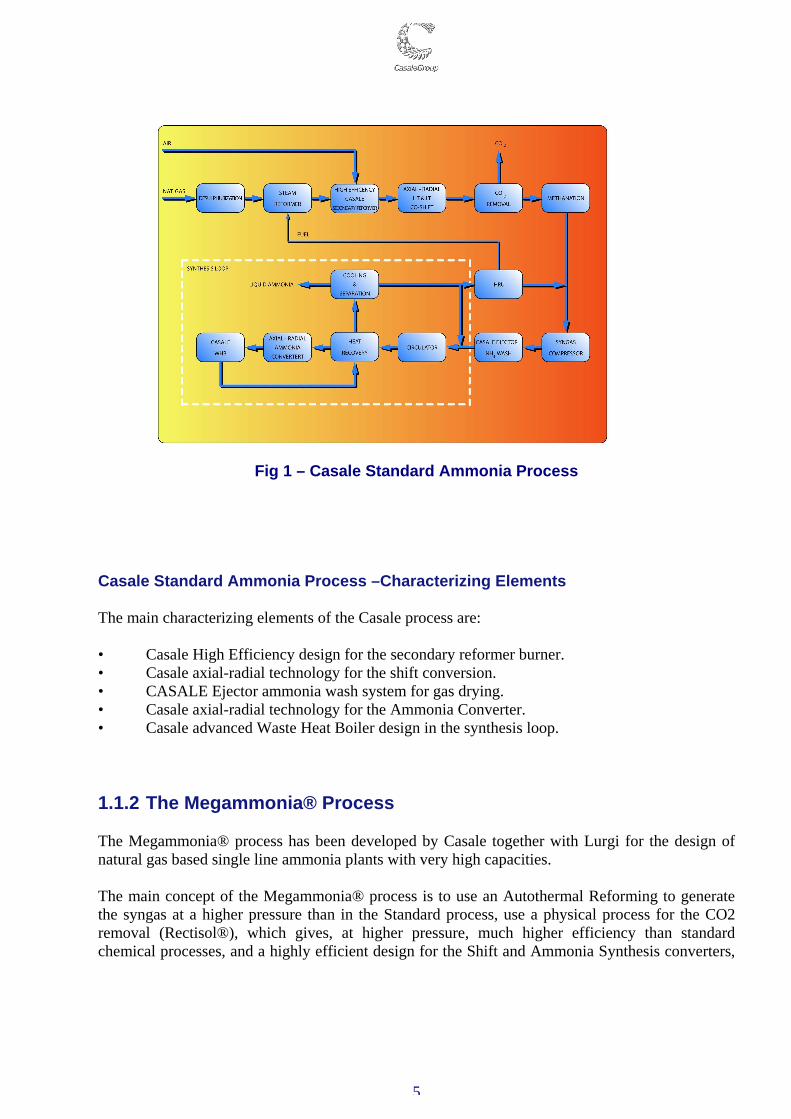
1. PROCESS FLOW SCHEME A new Ammonia or Urea plant start with the definition of the most suitable process flow scheme. Ammonia and Urea Casale has developed advanced technologies for the design of grass-root ammonia and urea plants, according to which new plants have been built or are under construction. 1.1 GRASS-ROOTS AMMONIA PLANTS Ammonia Casale can offer very efficient designs for the construction of grass-roots ammonia plants. For plant capacities up to 2500-3000 MTD, Casale proposes its Standard process, while if a capacity higher than 3000 MTD is required Casale can design the plant according to the Megammonia process. 1.1.1 The Standard Ammonia process The Casale Standard process for natural gas based ammonia plants is based on the classical steam reforming route. The main process steps are, as shown in fig.1: • Desulphurization • Primary and Secondary Reforming • HT and LT Shift Conversion • CO2 removal • Methanation • Syngas drying • Compression • Ammonia Synthesis • Hydrogen Recovery
5
Fig 1 – Casale Standard Ammonia Process
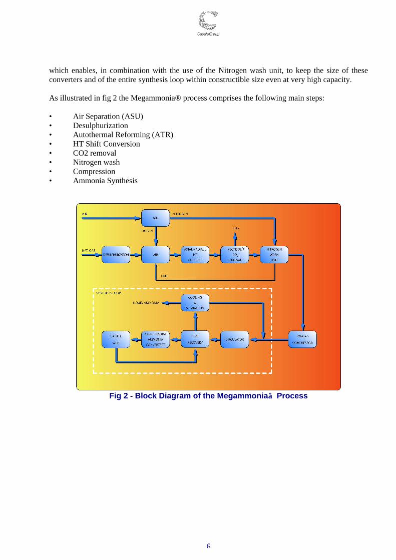
Casale Standard Ammonia Process –Characterizing Elements The main characterizing elements of the Casale process are: • Casale High Efficiency design for the secondary reformer burner. • Casale axial-radial technology for the shift conversion. • CASALE Ejector ammonia wash system for gas drying. • Casale axial-radial technology for the Ammonia Converter. • Casale advanced Waste Heat Boiler design in the synthesis loop. 1.1.2 The Megammonia® Process The Megammonia® process has been developed by Casale together with Lurgi for the design of natural gas based single line ammonia plants with very high capacities. The main concept of the Megammonia® process is to use an Autothermal Reforming to generate the syngas at a higher pressure than in the Standard process, use a physical process for the CO2 removal (Rectisol®), which gives, at higher pressure, much higher efficiency than standard chemical processes, and a highly efficient design for the Shift and Ammonia Synthesis converters,
6
which enables, in combination with the use of the Nitrogen wash unit, to keep the size of these converters and of the entire synthesis loop within constructible size even at very high capacity. As illustrated in fig 2 the Megammonia® process comprises the following main steps: • Air Separation (ASU) • Desulphurization • Autothermal Reforming (ATR) • HT Shift Conversion • CO2 removal • Nitrogen wash • Compression • Ammonia Synthesis
Fig 2 - Block Diagram of the Megammonia Process
7
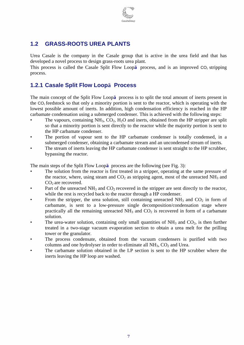
1.2 GRASS-ROOTS UREA PLANTS Urea Casale is the company in the Casale group that is active in the urea field and that has developed a novel process to design grass-roots urea plant. This process is called the Casale Split Flow Loop process, and is an improved CO2 stripping process. 1.2.1 Casale Split Flow Loop Process The main concept of the Split Flow Loop process is to split the total amount of inerts present in the CO2 feedstock so that only a minority portion is sent to the reactor, which is operating with the lowest possible amount of inerts. In addition, high condensation efficiency is reached in the HP carbamate condensation using a submerged condenser. This is achieved with the following steps: • The vapours, containing NH3, CO2, H2O and inerts, obtained from the HP stripper are split
so that a minority portion is sent directly to the reactor while the majority portion is sent to the HP carbamate condenser.
• The portion of vapour sent to the HP carbamate condenser is totally condensed, in a submerged condenser, obtaining a carbamate stream and an uncondensed stream of inerts.
• The stream of inerts leaving the HP carbamate condenser is sent straight to the HP scrubber, bypassing the reactor.
The main steps of the Split Flow Loop process are the following (see Fig. 3): • The solution from the reactor is first treated in a stripper, operating at the same pressure of
the reactor, where, using steam and CO2 as stripping agent, most of the unreacted NH3 and CO2 are recovered.
• Part of the unreacted NH3 and CO2 recovered in the stripper are sent directly to the reactor, while the rest is recycled back to the reactor through a HP condenser.
• From the stripper, the urea solution, still containing unreacted NH3 and CO2 in form of carbamate, is sent to a low-pressure single decomposition/condensation stage where practically all the remaining unreacted NH3 and CO2 is recovered in form of a carbamate solution.
• The urea-water solution, containing only small quantities of NH3 and CO2, is then further treated in a two-stage vacuum evaporation section to obtain a urea melt for the prilling tower or the granulator.
• The process condensate, obtained from the vacuum condensers is purified with two columns and one hydrolyser in order to eliminate all NH3, CO2 and Urea.
• The carbamate solution obtained in the LP section is sent to the HP scrubber where the inerts leaving the HP loop are washed.
8
Fig. 3 - Split Flow Loop Process
Casale Split Flow Loop process –Characterizing Elements The main elements characterizing the HP loop of the Split Flow Loop process are: • the Casale Full Condenser • the Casale-Dente high efficiency trays • the Casale High Efficiency Hydrolyser used in the process condensate treatment unit.
9
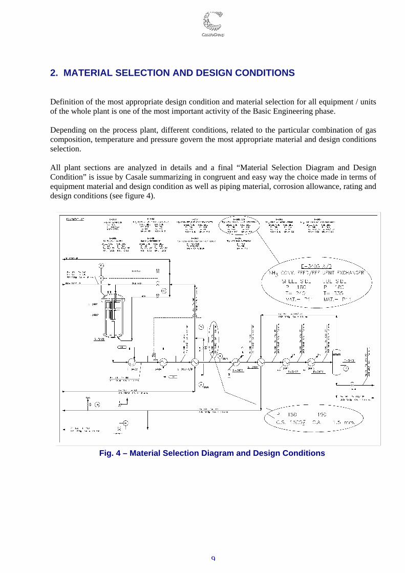
2. MATERIAL SELECTION AND DESIGN CONDITIONS Definition of the most appropriate design condition and material selection for all equipment / units of the whole plant is one of the most important activity of the Basic Engineering phase. Depending on the process plant, different conditions, related to the particular combination of gas composition, temperature and pressure govern the most appropriate material and design conditions selection. All plant sections are analyzed in details and a final “Material Selection Diagram and Design Condition” is issue by Casale summarizing in congruent and easy way the choice made in terms of equipment material and design condition as well as piping material, corrosion allowance, rating and design conditions (see figure 4).
Fig. 4 – Material Selection Diagram and Design Conditions
10
2.1 AMMONIA PLANT MATERIAL SELECTION The material selection for the front end of ammonia plant is basically governed by the fact that the process gas is practically a hydrogen rich gas at high temperature and moderate pressure. The front section of the ammonia plant fall therefore in what is called hydrogen service and the material selection must respect the minimum requirement stated by the API standard 941. The material selection takes moreover in consideration any possible chemical corrosion and the use of stainless steel is adopted wherever required in order to increase plant safety and reliability assuring trouble free plant run. The material selection for the synthesis loop of an ammonia plant is mainly governed by the fact that process gas is practically a hydrogen rich gas with considerable quantity of gaseous ammonia at high pressure and temperature. These two components and their combination at the typical operating condition of Ammonia loop require a specific material selection and equipment design, to avoid problems related to two specific phenomena: hydrogen attack and nitriding. Again the material selection must respect the requirement stated by the API standard 941 while the design of the relevant equipment requires deep knowledge of the problems and specific experience (see also chapter 8). 2.2 UREA PLANT MATERIAL SELECTION The urea process is characterized by the presence of quite aggressive process fluids like ammonium carbamate, ammonium carbonate and urea solution which require, especially under synthesis conditions (high pressure and high temperature) the utilization of special stainless steels. In principle all urea process utilize stainless steel, but while the low pressure, evaporation, vacuum and waste water treatment sections utilize standard commercial stainless steels (AISI-304L or AISI-316L), the synthesis loop is manufactured with special steels properly studied for Urea application. More details relevant to synthesis loop material are provided under para 8.2.
11
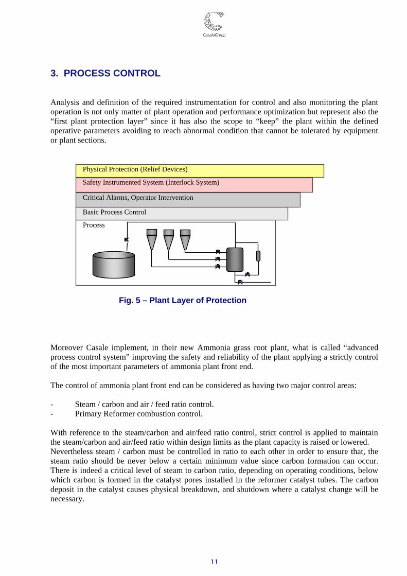
3. PROCESS CONTROL Analysis and definition of the required instrumentation for control and also monitoring the plant operation is not only matter of plant operation and performance optimization but represent also the “first plant protection layer” since it has also the scope to “keep” the plant within the defined operative parameters avoiding to reach abnormal condition that cannot be tolerated by equipment or plant sections.
Fig. 5 – Plant Layer of Protection
Moreover Casale implement, in their new Ammonia grass root plant, what is called “advanced process control system” improving the safety and reliability of the plant applying a strictly control of the most important parameters of ammonia plant front end. The control of ammonia plant front end can be considered as having two major control areas: - Steam / carbon and air / feed ratio control. - Primary Reformer combustion control. With reference to the steam/carbon and air/feed ratio control, strict control is applied to maintain the steam/carbon and air/feed ratio within design limits as the plant capacity is raised or lowered. Nevertheless steam / carbon must be controlled in ratio to each other in order to ensure that, the steam ratio should be never below a certain minimum value since carbon formation can occur. There is indeed a critical level of steam to carbon ratio, depending on operating conditions, below which carbon is formed in the catalyst pores installed in the reformer catalyst tubes. The carbon deposit in the catalyst causes physical breakdown, and shutdown where a catalyst change will be necessary.
Process
Basic Process Control
Critical Alarms, Operator Intervention
Safety Instrumented System (Interlock System)
Physical Protection (Relief Devices)
12
At the secondary reformer inlet, process air is added to the reformed gas. This flow must be controlled in ratio with the feed in order to ensure the right hydrogen / nitrogen ratio at the ammonia synthesis loop. Moreover the air / feed ratio should be never higher than a certain value to avoid undesired secondary reforming temperature rise above its design limits and / or unbalanced hydrogen to nitrogen ratio. The steam/carbon and air / feed ratio control scheme are configured according to a lead-lag control strategy. On increasing capacity the increase of steam will lead the increase of feed gas and in succession the increase of feed will lead the increase of process air. On decreasing capacity the process air decrease is followed by the feed decrease and in succession by the steam decrease. With reference to the combustion control, strict control is applied to maintain the reforming temperature within design limits whilst achieving efficient combustion with a controlled excess of air within the reformer box. Also the air to fuel ratio control scheme is configured to maintain the correct excess of combustion air when the firing demand is changing due to change in plant capacity or ambient conditions. For a load increase, combustion air increases first, then fuel gas will follow. For a load decrease, fuel gas reduces first, then combustion air will follow. Dedicated instrumentation for detection of all operating parameters is extensively adopted in Casale new grass root plants allowing continuous monitoring of plant operation as well as alarms for all critical parameters in order to have a prompt operator action in case of need.
13
4. INTERLOCK SYSTEM The purpose of the interlock system is to maintain a safe and reliable environment in the plant area protecting personnel, equipment and catalyst against malfunctioning of the control system and/or human mistakes. Speaking about causes and effects of each interlock logics, Casale usually group them as follow: I. Main Interlocks Logic (E) II. Partial Interlocks Logic (I) The first set includes all interlocks that lead to entire unit shutdown and/or main machines shutdown up to the general plant shutdown. Apart of general and section shut-down situation, above mentioned, we will have partial shut-down, limited to the operating conditions of individual equipment or to the feeding of some streams to section of the plant (i.e. single cause single action logics). We call them as Partial Interlocks. A dedicated Emergency Shutdown System (ESD) shall manage the Main interlock logic, while the Partial Interlock Logic could be managed directly by DCS or by ESD if required by Client. It is important to highlight that dedicated instrumentation, separate from those used for monitoring and process control, is provided for the Emergency Shutdown System improving the reliability of the entire system. Moreover for the more critical interlock logics the 2 out of 3 logic is also adopted. Casale always perform a systematic analysis of the entire plant interlock system providing a full set of documentation for their correct development and implementation during the detail engineering phase like: “Emergency Shut Down System Description”, “Interlock Logic Diagram” and “Cause & Effect Diagram”. As standard procedure the above final documentation including the “Piping and Instrumentation Diagram” are always subject to the HAZOP and SIL studies (see chapter 6 and 7) with the target to analyze all hazard and operability issues as well as the reliability that each individual Shutdown Interlock Logic must have.
14
5. SAFETY RELIEF SYSTEM Analysis and definition of the safety relief system able to manage any possible overpressure that may be caused by plant mal-operations, utility failure of failure of process control and emergency interlock system as well as fire contingency is of the most importance during the design of a new grass-root plant. The sizing, selection and installation of pressure relieving devices in a process plant are subject to the minimum requirement set by API standard 520 and 521. As the result of the above analysis a complete “Relief System Summary” is issued by Casale summarizing the quantity of gas to be relived for any possible overpressure contingency of any equipment or plant section. The above summary is then used for the sizing of the individual Pressure Safety Valves considering the worst reliving scenario. Nowadays, in order to overcome all the correlated environmental issues, process plants are always equipped with a flare system. The flare system has the duty to collect all source of gaseous emission (basically safety valves and vents) and send them to a common Flare Stack where the harmful gases will be burned and then safely discharged to the atmosphere. In new ammonia plant usually two flares system are provided, one for the emission from the front end, the second for the emission from the back end (compressor, synthesis and refrigeration section). The two systems are kept separated because the emissions from the back end are contaminated with ammonia, while the emissions from the front end contain carbon dioxide. The mix of streams containing ammonia and carbon dioxide is avoided since they can produce carbamate causing problem of plugging. In urea plants all process discharge points are conveyed in a blow down system that collects all the potential ammonia emissions at safe location thus preventing issues to the plant environment. In addition, all the process drains are collected in a closed drain system, thus limiting process spillages on the floor and consequently to the rain water system. It is important to highlight that as per Casale philosophy the plants are always equipped with process control vents in order to prevent the reliving through Pressure Safety Valves improving in such way their reliability. Pressure safety valves usually need in fact a general overhaul after reliving. In particular, for Urea plants design special care shall be taken when designing safety valves for urea or carbamate service especially at high pressure. In fact, such fluids are highly corrosive and prone to crystallize even at high temperature. Urea Casale has developed its own internal standard for designing and manufacturing this type of safety valves (urea service valves). This standard is being adopted by a certain number of selected manufacturers that are having experience with such kind of design and with the manufacturing of the utilized materials.
15
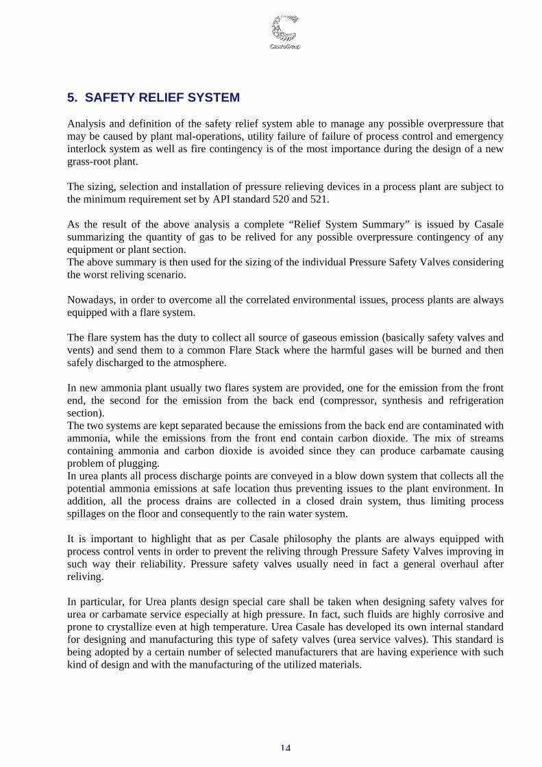
In particular, all high pressure safety valves for Urea Service shall be provided of:
• Steam jacket on nozzle. • Low pressure steam nozzle for disk and seat washing.
Connection high pressure side
Lenticular flanges according to CASALE std.
Nozzle material HVD-1
Disc material HVD-1
Other internal parts material
AISI 316L UG
No dead space is allowed between body valve and process line. The valve shall be installed directly on process line without any adjusting spool.
16
6. HAZOP STUDY A Hazard and Operability (HAZOP) study is carried out to check the Piping & Instrument Diagrams of relevant Plant Project. The study covers normal continuous operation and, when necessary, start-up, shut-down and maintenance operations are also analyzed. The main aims of the HAZOP study are: • To identify possible deviations from the intended operation conditions that can cause harm or
operational disruption (accidental events); • To verify the compliance with good engineering practice; • To propose some actions, where necessary, in order to improve the safety level or the
operability of the systems to be installed. Essentially the examination procedure takes a full description of the process, schematically questions every part of it to discover how credible deviations from the design can occur and decides whether these deviations can give rise to hazards. The technique adopted is to divide the P&IDs into nodes capturing a significant design intention, and to review the operation of the plant and equipment within the node, while focusing on major hazards and operability issues. The questioning is focused in turn on every part of the design. Each part is subjected to a number of questions formulated around a number of “guide words” exploring every conceivable way in which that design could deviate from the design intention. This usually produces a number of theoretical deviations and each deviation is then considered to decide how it could be caused and what would be the consequences. Some of the causes may be unrealistic and so the derived consequences will be rejected as not meaningful. Some of the consequences may be trivial and would be considered no further. However, there may be some deviations with both causes that are conceivable and consequences that are potentially hazardous. These potential hazard are then noted for remedial action. Any recommendation regarding safety issues normally comes out as a result of a trade-off between the expected frequency of an accident and the expected consequences of it. It is important to apply the same philosophy to all the Units of a plant. The plant is therefore analysed identifying systems and study nodes for easy reference on the related P&Id’s. Each node shall be reviewed using the relevant guidewords and parameters, identifying deviations, causes, consequences, safeguards and actions if any. Having examined one part of the design (node) and recorded any potential hazards associated with it, the study progresses to focus on the next part of the design. The examination is repeated until the whole plant has been studied.

17
Hazop study is normally carried out by multi-disciplinary team. There are two types of team member, namely those who will make a technical contribution and those who play a supporting and structuring role. The examination requires the team to have a detailed knowledge of the way the plant is intend to work. This means a blend of those concerned with design of the plant and those concerned with its operation. The technique of using guidewords generates a very large number of questions. For most purpose it is essential that the team contain enough people with sufficient knowledge and experience to answer the majority of those questions without recourse to further expertise. Because examination sections are highly structured and very systematic, it is necessary to have someone to control the discussion. We will call this person the “study leader” or “hazop chairman”. In addition to the study leader it is desirable to have a further supporting member of the team to make a note of the hazards as they are detected. This person is known as the “hazop secretary”. As a result the HAZOP study highlight a list of recommendations to be included or considered in reviewing P&I diagrams before their final issue.
18
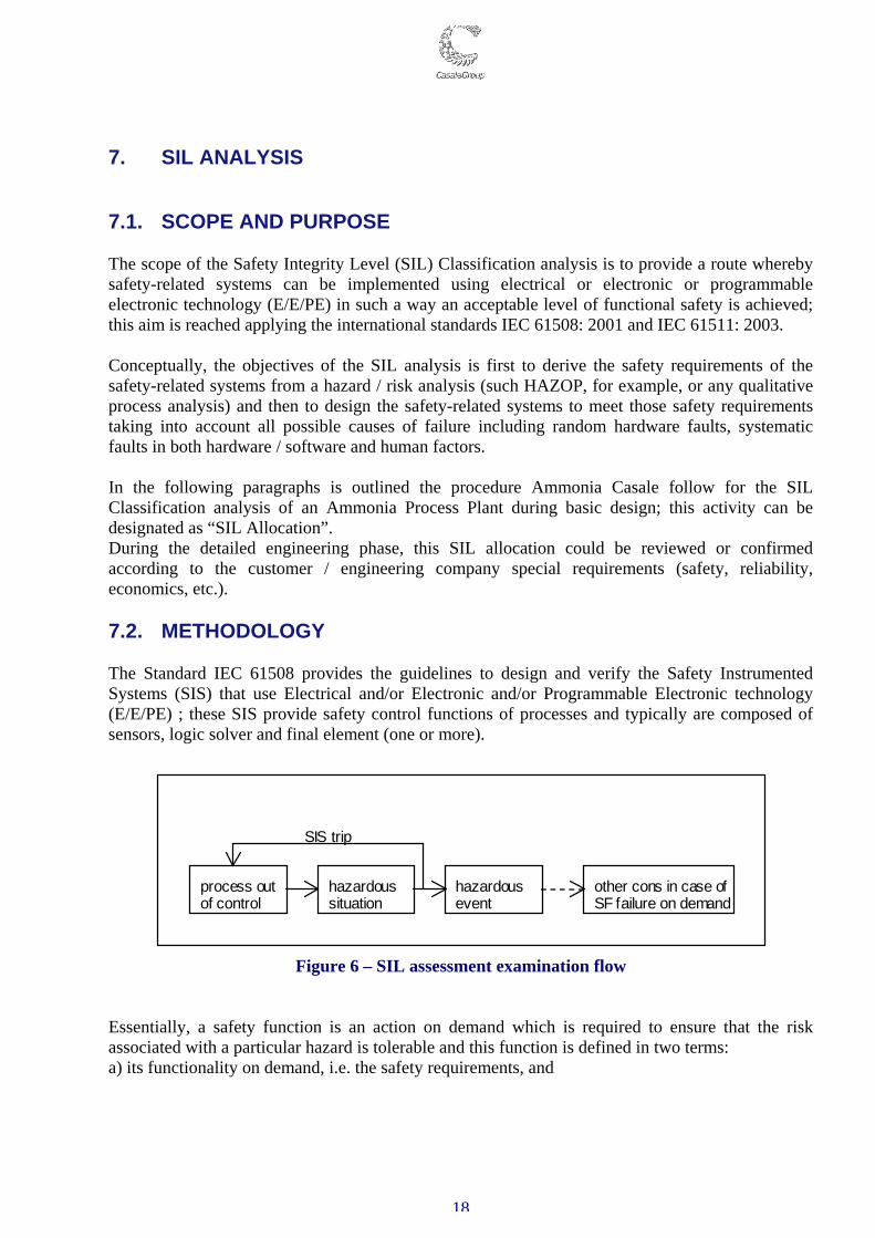
7. SIL ANALYSIS 7.1. SCOPE AND PURPOSE The scope of the Safety Integrity Level (SIL) Classification analysis is to provide a route whereby safety-related systems can be implemented using electrical or electronic or programmable electronic technology (E/E/PE) in such a way an acceptable level of functional safety is achieved; this aim is reached applying the international standards IEC 61508: 2001 and IEC 61511: 2003. Conceptually, the objectives of the SIL analysis is first to derive the safety requirements of the safety-related systems from a hazard / risk analysis (such HAZOP, for example, or any qualitative process analysis) and then to design the safety-related systems to meet those safety requirements taking into account all possible causes of failure including random hardware faults, systematic faults in both hardware / software and human factors. In the following paragraphs is outlined the procedure Ammonia Casale follow for the SIL Classification analysis of an Ammonia Process Plant during basic design; this activity can be designated as “SIL Allocation”. During the detailed engineering phase, this SIL allocation could be reviewed or confirmed according to the customer / engineering company special requirements (safety, reliability, economics, etc.). 7.2. METHODOLOGY The Standard IEC 61508 provides the guidelines to design and verify the Safety Instrumented Systems (SIS) that use Electrical and/or Electronic and/or Programmable Electronic technology (E/E/PE) ; these SIS provide safety control functions of processes and typically are composed of sensors, logic solver and final element (one or more).
process out of control
hazardous situation
hazardous event
other cons in case of SF failure on demand
SIS trip
Figure 6 – SIL assessment examination flow
Essentially, a safety function is an action on demand which is required to ensure that the risk associated with a particular hazard is tolerable and this function is defined in two terms: a) its functionality on demand, i.e. the safety requirements, and
19
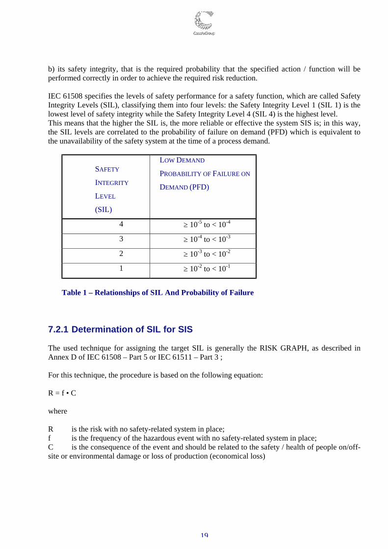
b) its safety integrity, that is the required probability that the specified action / function will be performed correctly in order to achieve the required risk reduction. IEC 61508 specifies the levels of safety performance for a safety function, which are called Safety Integrity Levels (SIL), classifying them into four levels: the Safety Integrity Level 1 (SIL 1) is the lowest level of safety integrity while the Safety Integrity Level 4 (SIL 4) is the highest level. This means that the higher the SIL is, the more reliable or effective the system SIS is; in this way, the SIL levels are correlated to the probability of failure on demand (PFD) which is equivalent to the unavailability of the safety system at the time of a process demand.
SAFETY
INTEGRITY
LEVEL
(SIL)
LOW DEMAND
PROBABILITY OF FAILURE ON
DEMAND (PFD)
4 ≥ 10-5 to < 10-4
3 ≥ 10-4 to < 10-3
2 ≥ 10-3 to < 10-2
1 ≥ 10-2 to < 10-1
Table 1 – Relationships of SIL And Probability of Failure 7.2.1 Determination of SIL for SIS The used technique for assigning the target SIL is generally the RISK GRAPH, as described in Annex D of IEC 61508 – Part 5 or IEC 61511 – Part 3 ; For this technique, the procedure is based on the following equation: R = f • C where R is the risk with no safety-related system in place; f is the frequency of the hazardous event with no safety-related system in place; C is the consequence of the event and should be related to the safety / health of people on/off-site or environmental damage or loss of production (economical loss)
20
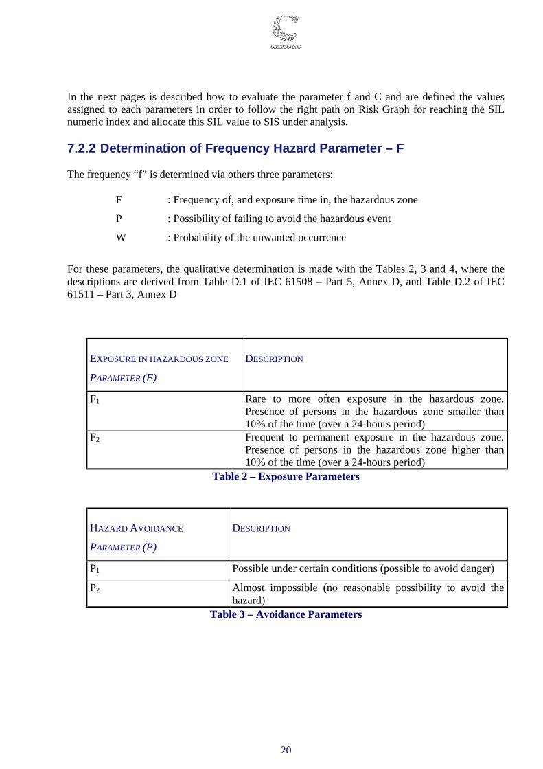
In the next pages is described how to evaluate the parameter f and C and are defined the values assigned to each parameters in order to follow the right path on Risk Graph for reaching the SIL numeric index and allocate this SIL value to SIS under analysis. 7.2.2 Determination of Frequency Hazard Parameter – F The frequency “f” is determined via others three parameters:
F : Frequency of, and exposure time in, the hazardous zone
P : Possibility of failing to avoid the hazardous event
W : Probability of the unwanted occurrence
For these parameters, the qualitative determination is made with the Tables 2, 3 and 4, where the descriptions are derived from Table D.1 of IEC 61508 – Part 5, Annex D, and Table D.2 of IEC 61511 – Part 3, Annex D
EXPOSURE IN HAZARDOUS ZONE
PARAMETER (F)
DESCRIPTION
F1 Rare to more often exposure in the hazardous zone. Presence of persons in the hazardous zone smaller than 10% of the time (over a 24-hours period)
F2 Frequent to permanent exposure in the hazardous zone. Presence of persons in the hazardous zone higher than 10% of the time (over a 24-hours period)
Table 2 – Exposure Parameters
HAZARD AVOIDANCE
PARAMETER (P)
DESCRIPTION
P1 Possible under certain conditions (possible to avoid danger)
P2 Almost impossible (no reasonable possibility to avoid the hazard)
Table 3 – Avoidance Parameters
21
PROBABILITY OF
UNWANTED OCCURRENCE
PARAMETER (W)
DESCRIPTION
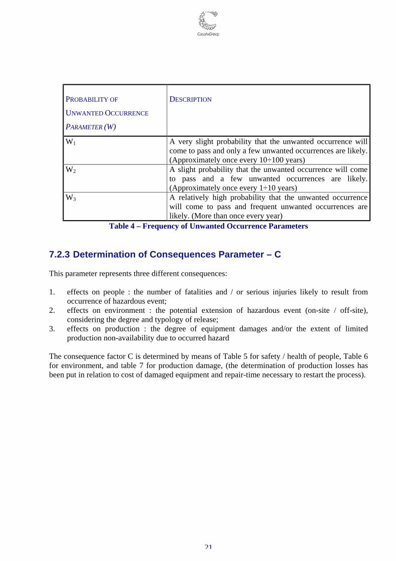
W1 A very slight probability that the unwanted occurrence will come to pass and only a few unwanted occurrences are likely. (Approximately once every 10÷100 years)
W2 A slight probability that the unwanted occurrence will come to pass and a few unwanted occurrences are likely. (Approximately once every 1÷10 years)
W3 A relatively high probability that the unwanted occurrence will come to pass and frequent unwanted occurrences are likely. (More than once every year)
Table 4 – Frequency of Unwanted Occurrence Parameters 7.2.3 Determination of Consequences Parameter – C This parameter represents three different consequences: 1. effects on people : the number of fatalities and / or serious injuries likely to result from
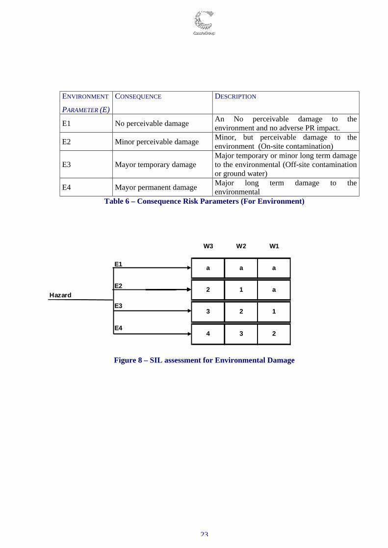
occurrence of hazardous event; 2. effects on environment : the potential extension of hazardous event (on-site / off-site),
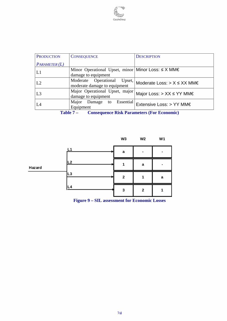
considering the degree and typology of release; 3. effects on production : the degree of equipment damages and/or the extent of limited
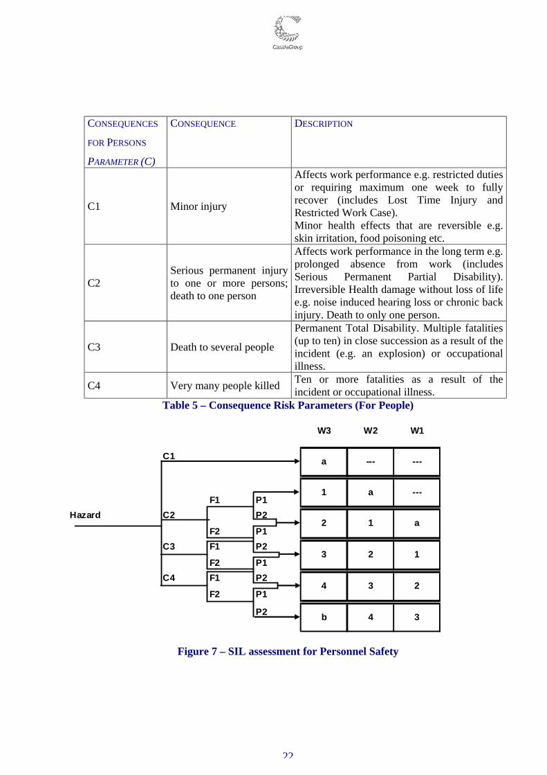
production non-availability due to occurred hazard The consequence factor C is determined by means of Table 5 for safety / health of people, Table 6 for environment, and table 7 for production damage, (the determination of production losses has been put in relation to cost of damaged equipment and repair-time necessary to restart the process).
22
CONSEQUENCES
FOR PERSONS
PARAMETER (C)
CONSEQUENCE DESCRIPTION
C1 Minor injury
Affects work performance e.g. restricted duties or requiring maximum one week to fully recover (includes Lost Time Injury and Restricted Work Case). Minor health effects that are reversible e.g. skin irritation, food poisoning etc.
C2 Serious permanent injury to one or more persons; death to one person
Affects work performance in the long term e.g. prolonged absence from work (includes Serious Permanent Partial Disability). Irreversible Health damage without loss of life e.g. noise induced hearing loss or chronic back injury. Death to only one person.
C3 Death to several people
Permanent Total Disability. Multiple fatalities (up to ten) in close succession as a result of the incident (e.g. an explosion) or occupational illness.
C4 Very many people killed Ten or more fatalities as a result of the incident or occupational illness.
Table 5 – Consequence Risk Parameters (For People)
W3 W2 W1
C1
F1 P1Hazard C2 P2
F2 P1C3 F1 P2
F2 P1C4 F1 P2
F2 P1
P2
a --- ---
1 a ---
2 1 a
3 2 1
4 3 2
b 4 3
Figure 7 – SIL assessment for Personnel Safety
23
ENVIRONMENT
PARAMETER (E)
CONSEQUENCE DESCRIPTION
E1 No perceivable damage An No perceivable damage to the environment and no adverse PR impact.
E2 Minor perceivable damage Minor, but perceivable damage to the environment (On-site contamination)
E3 Mayor temporary damage Major temporary or minor long term damage to the environmental (Off-site contamination or ground water)
E4 Mayor permanent damage Major long term damage to the environmental
Table 6 – Consequence Risk Parameters (For Environment)
W3 W2 W1
E1
E2Hazard
E3
E4
3 2 1
4 3 2
a a a
2 1 a
Figure 8 – SIL assessment for Environmental Damage
24
PRODUCTION
PARAMETER (L) CONSEQUENCE DESCRIPTION
L1 Minor Operational Upset, minor damage to equipment
Minor Loss: ≤ X MM€
L2 Moderate Operational Upset, moderate damage to equipment Moderate Loss: > X ≤ XX MM€
L3 Major Operational Upset, major damage to equipment Major Loss: > XX ≤ YY MM€
L4 Major Damage to Essential Equipment Extensive Loss: > YY MM€
Table 7 – Consequence Risk Parameters (For Economic)
W3 W2 W1
L1
L2Hazard
L3
L4
a - -
-a1
1 a
3 2 1
2
Figure 9 – SIL assessment for Economic Losses
25
7.3. SIL Allocation Report The above procedure to determine consequences of failure on demand are recorded for each loop (SIS). If failure on demand has multiple consequences, all consequences are analysed, and the most conservative SIL is used for that function. The overall SIL required to the each function is the higher among those defined by applying the matrices in Figures 7, 8 and 9. During the detail engineering phase is task of the engineering company to verify and apply the target SIL level assigned to each SIS function by both installing enough reliable instrumentation (sensor, logic solver and final element) or duplicating it if necessary. It is finally duty of plant operative people to keep the installed SIS functions operative at the required SIL level performing the required maintenance to avoid degradation of their reliability that leads to declassing the SIL level from the target figure.
26
8. CASALE PROPRIETARY EQUIPMENT Ammonia and Urea plants incorporate a certain number of critical items. Such critical items are of the most importance both for the performance, safety and reliability plant point of views. Ammonia and Urea Casale directly supply a certain number of proprietary items and can also supply the critical equipment that characterize and define its ammonia and urea plants in the world. Ammonia Casale proprietary items are:
- Ammonia synthesis converter. - Synloop waste heat boiler / BFW pre-heater. - Axial radial Shift converters. - Secondary reformer burner. - Make up gas wash ejector.
Urea Casale proprietary items are: - Urea reactor High Efficiency Trays - Urea hydrolizer High Efficiency Trays - High Efficiency internals for HP Full Condenser - HP Ejector for Split Flow Loop Process and critical items are: - Urea reactor - Urea Stripper - HP Full Condenser - HP Scrubber
8.1 Safety and Reliability in Ammonia Synthesis Converter and
Downstream Exchanger Ammonia synthesis converter and downstream heat exchanger are key items in ammonia plants. Their reliability is essential, as a plant cannot run without them. In addition, the ammonia synthesis converter is the reactor with the longest run between catalyst changes, since it must run for 10-15 years. Ammonia catalyst, once reduced, should not come in contact with oxygen since is highly pyrophoric. Therefore converters should operate between catalyst changes without repairs or inspections. To achieve this result without any impact on the safety and reliability of plants, several aspects have to be considered as converters are subject to different metallurgical deterioration phenomena, and, as they have a complicated mechanical design with multiple catalyst beds. From a safety point of view, the catalyst re-placements and inspections are critical as well.
27
8.1.1 Ammonia Converter Due to the aggressive environment created by the combination of high pressure, high temperature and peculiar gas composition, in which the converter operates, the first aspect to be considered in the design of the Ammonia synthesis converters, to ensure a high reliability, is the materials selection. The concurrence of Hydrogen related damages (High Temperature Hydrogen Attack / Hydrogen Debonding) and Nitriding is typical of the Ammonia synthesis loop, particularly of the ammonia converter, where the highest temperatures and pressures are combined with high content of hydrogen and ammonia. Since the detrimental effects of the environment on the materials increases by increasing the temperature the latter needs to be kept as low as possible. Casale philosophy consists in a suitable material selection and generally keeping the materials at a lower temperature through a suitable thermal insulation and/or gas flush. This concept allows intrinsically increasing the safety of high-pressure parts. The Ammonia converter pressure vessel has much lower operating temperature than the internals since is fluxed with the low temperature inlet gas, while is protected from the high temperature sections by the internal cartridge. Therefore ferritic materials such Carbon steel or Chrome-Moly steels are generally used, selected according to the API standard 941. In any case Casale selects 1 ¼ Cr ½ Mo steel as minimum requirement, even if not mandatory according to API standard, due to its superior reliability in the hydrogen service compared to Carbon and Moly steels. Since the ferritic components of hot pressure parts (typically outlet nozzle and start-up nozzle) suffer from nitriding, a designer can consider welding overlay the parts with austenitic materials or high nickel alloys. However this solution does not protect against Hydrogen debonding. For this reason, Casale design considers to thermally insulate the hot vessel regions rather than cladding them. The insulation consists of an Inconel liner filled with insulating materials (e.g. ceramic fiber). The insulation is easily accessible, easy to inspect and simply replaceable. Ammonia converter internals are exposed to the highest temperature and therefore the element where the combined effect of Hydrogen and ammonia is strongest. The use of AISI 321 stainless steel for the internals of ammonia converters is preferable compared to other stainless steels since is stabilized with Titanium. In this way there is no risk of carbides precipitation (causing embrittlement of the materials in hydrogen service) that, on the contrary, is possible for grades 304 or 316. For thin elements, where also the use of stainless steel is subject to failure since the thickness of the component is comparable to the nitrided layer, it is necessary to adopt inconel alloy 600 which is not susceptible to the problem. Also for the interchanger tubes working above a critical temperature (450 °C) selection of Inconel 600 is advised. All the expansion joints bellows (also the ‘cold’ ones – in order to avoid possible mistakes) should be in Inconel alloy 600.
28
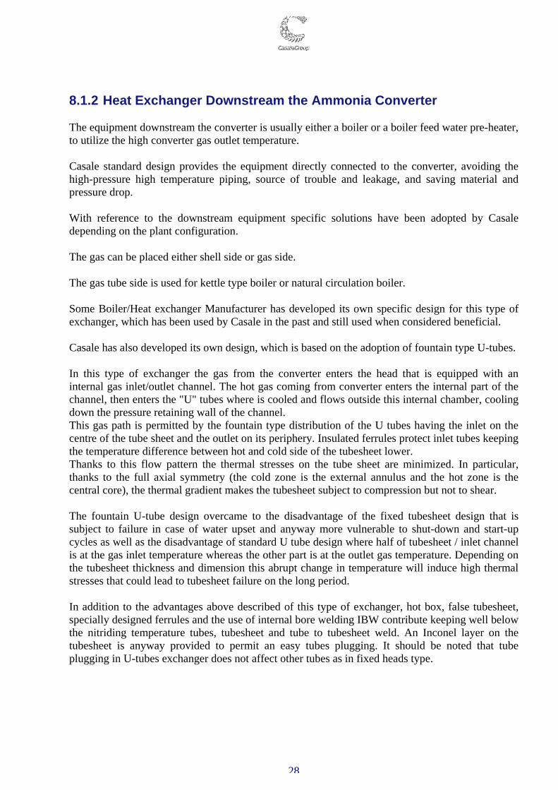
8.1.2 Heat Exchanger Downstream the Ammonia Converter The equipment downstream the converter is usually either a boiler or a boiler feed water pre-heater, to utilize the high converter gas outlet temperature. Casale standard design provides the equipment directly connected to the converter, avoiding the high-pressure high temperature piping, source of trouble and leakage, and saving material and pressure drop. With reference to the downstream equipment specific solutions have been adopted by Casale depending on the plant configuration. The gas can be placed either shell side or gas side. The gas tube side is used for kettle type boiler or natural circulation boiler. Some Boiler/Heat exchanger Manufacturer has developed its own specific design for this type of exchanger, which has been used by Casale in the past and still used when considered beneficial. Casale has also developed its own design, which is based on the adoption of fountain type U-tubes. In this type of exchanger the gas from the converter enters the head that is equipped with an internal gas inlet/outlet channel. The hot gas coming from converter enters the internal part of the channel, then enters the "U" tubes where is cooled and flows outside this internal chamber, cooling down the pressure retaining wall of the channel. This gas path is permitted by the fountain type distribution of the U tubes having the inlet on the centre of the tube sheet and the outlet on its periphery. Insulated ferrules protect inlet tubes keeping the temperature difference between hot and cold side of the tubesheet lower. Thanks to this flow pattern the thermal stresses on the tube sheet are minimized. In particular, thanks to the full axial symmetry (the cold zone is the external annulus and the hot zone is the central core), the thermal gradient makes the tubesheet subject to compression but not to shear. The fountain U-tube design overcame to the disadvantage of the fixed tubesheet design that is subject to failure in case of water upset and anyway more vulnerable to shut-down and start-up cycles as well as the disadvantage of standard U tube design where half of tubesheet / inlet channel is at the gas inlet temperature whereas the other part is at the outlet gas temperature. Depending on the tubesheet thickness and dimension this abrupt change in temperature will induce high thermal stresses that could lead to tubesheet failure on the long period. In addition to the advantages above described of this type of exchanger, hot box, false tubesheet, specially designed ferrules and the use of internal bore welding IBW contribute keeping well below the nitriding temperature tubes, tubesheet and tube to tubesheet weld. An Inconel layer on the tubesheet is anyway provided to permit an easy tubes plugging. It should be noted that tube plugging in U-tubes exchanger does not affect other tubes as in fixed heads type.
29
Fig. 10 – High temperature gas in tube boiler
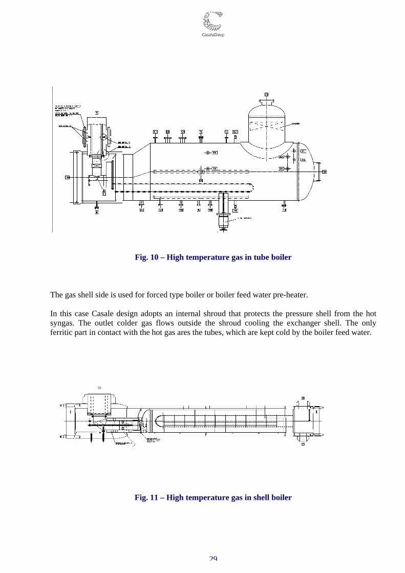
The gas shell side is used for forced type boiler or boiler feed water pre-heater. In this case Casale design adopts an internal shroud that protects the pressure shell from the hot syngas. The outlet colder gas flows outside the shroud cooling the exchanger shell. The only ferritic part in contact with the hot gas ares the tubes, which are kept cold by the boiler feed water.
Fig. 11 – High temperature gas in shell boiler
30
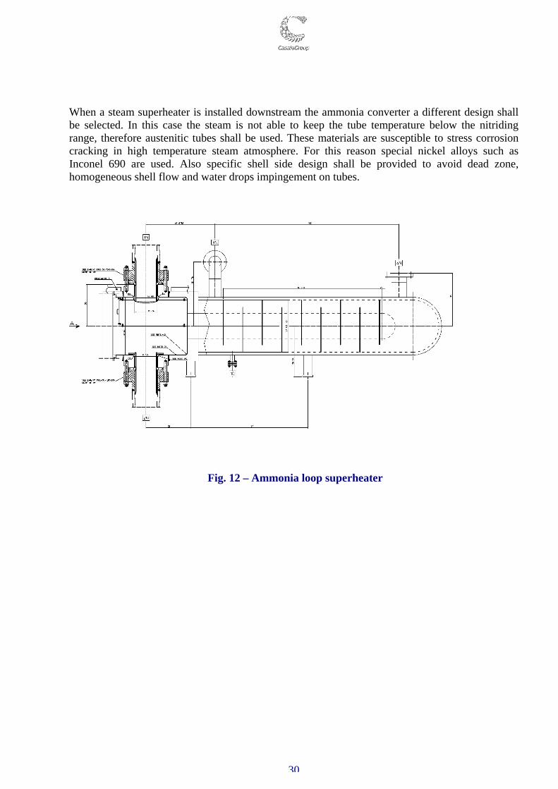
When a steam superheater is installed downstream the ammonia converter a different design shall be selected. In this case the steam is not able to keep the tube temperature below the nitriding range, therefore austenitic tubes shall be used. These materials are susceptible to stress corrosion cracking in high temperature steam atmosphere. For this reason special nickel alloys such as Inconel 690 are used. Also specific shell side design shall be provided to avoid dead zone, homogeneous shell flow and water drops impingement on tubes.
Fig. 12 – Ammonia loop superheater
31
8.2 SAFETY AND RELIABILITY IN CRITICAL ITEMS OF UREA
SYNTESIS LOOP The pieces of Urea synthesis equipment are key items in Urea plants. Their reliability is essential, as a plant cannot run without them and repairs are generally expensive and time consuming. In addition, they operate at high pressure, generally about 140 bar, and therefore, catastrophic failure is possible, threatening the safety of the plant and its operators. The risk is increased, compared to common high pressure equipments, by the process fluid high corrosion characteristic. In this equipment safety and reliability are, therefore, strictly connected. An adequate level of both aspects is achieved through several steps: - Accurate material selection - Proper design - Well controlled construction - Accurate maintenance and inspection. In all these phases, Casale’s long experience and innovative design guarantees specific solution to achieve the best results. Material selection For the synthesis equipment, it should be noted that the activities in the revamping field have brought to Casale a wide experience in all type of process and materials, experience that has been transferred to the new plant design. Specifically, all types of materials used in contact with the process fluid, such as urea grade stainless steel, duplex stainless steel, titanium as well as zirconium, are well known to Casale. Casale has selected 25-22-2 Cr-Ni-Mo type stainless steel, as construction material for these pieces of equipment. Casale has developed detailed specifications to cover the material production, testing and welding, in order to assure the highest quality and resistance. These specifications are continuously updated on the basis of the improved experience and the technical progress. In addition, Casale has selected a restricted number of manufacturers that have been qualified for the construction of this equipment. In any case, the material selection is never separate from the process design. A typical example is the specific features to guarantee in each spot the correct amount of oxygen required to the corrosion resistance of material. Design Even an accurate material selection could not guarantee by itself alone the reliability and safety of the equipment, since the corrosion, even if under control, is always present. Moreover, construction defects or incorrect operation could damage the equipment ant threaten its safety.
32
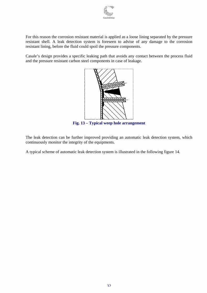
For this reason the corrosion resistant material is applied as a loose lining separated by the pressure resistant shell. A leak detection system is foreseen to advise of any damage to the corrosion resistant lining, before the fluid could spoil the pressure components. Casale’s design provides a specific leaking path that avoids any contact between the process fluid and the pressure resistant carbon steel components in case of leakage.
Fig. 13 – Typical weep hole arrangement
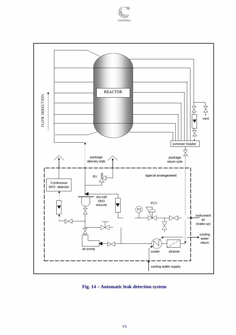
The leak detection can be further improved providing an automatic leak detection system, which continuously monitor the integrity of the equipments. A typical scheme of automatic leak detection system is illustrated in the following figure 14.
33
Fig. 14 – Automatic leak detection system
34
Construction The equipment construction is one of the most sensitive phases, because all the advantages of a good design can be lost in an inaccurate construction. Defects, mistakes or incorrect procedures during construction are the first cause of equipment failure. The Casale philosophy is to utilize only few selected manufacturers with a long experience in high pressure Urea equipment. These manufacturers, which continuously work with Casale, are familiar with Casale’s specifications and designs. In any Event, well-defined procedures are supplied to the manufacturers and all the critical construction phases are monitored by experienced inspectors accustomed with this specific type of construction. Accurate tests, well beyond code requirements, are foreseen to certify the accurateness of each specific construction. Maintenance and inspection These pieces of equipment shall undergo a continuous monitoring and testing all along their life to guarantee a trouble-free operation. Casale equipment is typically designed keeping in mind plant overhauling every three years, considering that all the required maintenance and inspection activities are adequately be performed as scheduled. To closely monitor all the equipment along their life, Casale has put in place a specific program, the pro-active maintenance system (PAMS). PAMS is part of the Casale know-how and summarizes the continuous effort applied in up-grading of Casale designs and construction solutions, materials investigations and properties’ assurance, quality controls, and last but not least, the inspection feed-back on operating equipment. Its prime responsibility is to monitor equipment reliability & integrity and suggest corrective actions to ensure reliable and efficient plant operation. PAMS develops & manages inspection and repair strategies to grant integrity assurance of HP Urea Equipment and Synthesis Loop Piping in a cost effective manner. Safe and efficient plant operation can be definitely influenced by ineffective diagnostic integrity surveys and unsuited maintenance approach. The inspection and repair strategies are mainly focused on the following objectives:
- To preserve the pressure-bearing components from the exposure to the high aggressive carbammate environment.
- To discern important findings requiring immediate actions and consideration. - To extend reliability & life-integrity of operating components. - To ensure compliance with Pressure System Safety Regulations.
35
- To assess remaining life of the equipment - To propose pro-active repair activities to extend equipment operating life
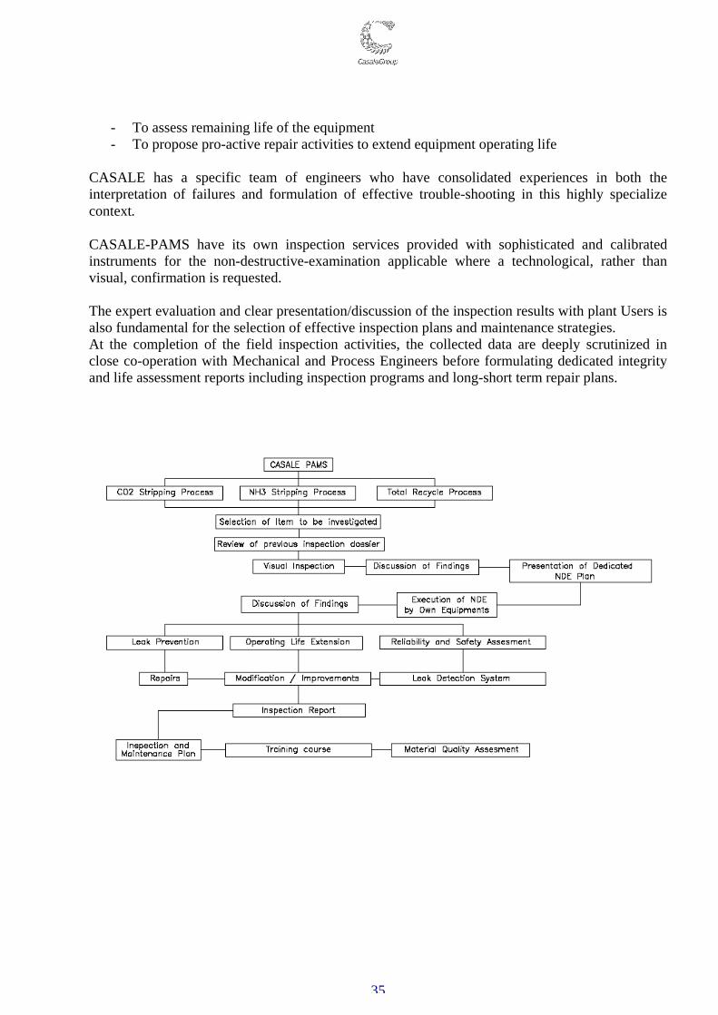
CASALE has a specific team of engineers who have consolidated experiences in both the interpretation of failures and formulation of effective trouble-shooting in this highly specialize context. CASALE-PAMS have its own inspection services provided with sophisticated and calibrated instruments for the non-destructive-examination applicable where a technological, rather than visual, confirmation is requested. The expert evaluation and clear presentation/discussion of the inspection results with plant Users is also fundamental for the selection of effective inspection plans and maintenance strategies. At the completion of the field inspection activities, the collected data are deeply scrutinized in close co-operation with Mechanical and Process Engineers before formulating dedicated integrity and life assessment reports including inspection programs and long-short term repair plans.
36
9. CONCLUSIONS This paper has described all the aspects relevant to process safety and reliability that are always taken in consideration by Casale during the design stages of new grass-root plants in addition to process performance. The design of a new plant requires deep knowledge on all engineering discipline, about possible problem as well as a specific experience in the relevant process. Casale as engineering company has in-house specialist able to manage in efficient and professional way all the issue related to plant safety and reliability. Moreover, Casale, as supplier of a wide range of proprietary equipment, has developed several solutions that best suits all needs required both for plant retrofitting to new plants design, which have been proven their reliability and safety run in the industry in several pants.
.