process station - ac 800f - ufam - universidade federal do...
TRANSCRIPT
EngineerIT
Control Builder F
Engineering ManualProcess Station - AC 800F
Gross Automation, 1725 South Johnson Road, New Berlin, WI 53146, www.ssacsales.com, 800-349-5827

Notice
Information provided in this manual is subject to change without prior notice andrepresents no obligation on the part of ABB Automation Products.
The industrial standards and regulations (e.g. DIN, VDE, VDI, etc.) applicable in theFederal Republic of Germany are used. Outside the Federal Republic of Germany, therelevant national specifications, standards and regulations must be observed.
ABB Automation Products reserves all rights, especially those arising out of BGB,UWG, UrhG as well as out of industrial property rights (patents, utility models,trademarks, service trademarks and flavor samples).
The designations used and the products shown/mentioned in this manual have not beenspecifically marked regarding existing industrial property rights.
No part of this manual may be reproduced without prior written permission from ABBAutomation Products.
Should you find any mistakes in this manual, please make a copy of the appropriatepage(s) and send it/them to us with your comments. Any suggestions which may help toimprove comprehension or clarity will also be gratefully accepted.
Please send your suggestions to:
Product Management Dept., DEAPR/LMS-Hannover, Fax: +49 (0)511 6782 701
Gross Automation, 1725 South Johnson Road, New Berlin, WI 53146, www.ssacsales.com, 800-349-5827
Engineering ManualProcess Station – ABB FieldController 800
Gross Automation, 1725 South Johnson Road, New Berlin, WI 53146, www.ssacsales.com, 800-349-5827

Gross Automation, 1725 South Johnson Road, New Berlin, WI 53146, www.ssacsales.com, 800-349-5827
Process Station ABB FieldController 800
3
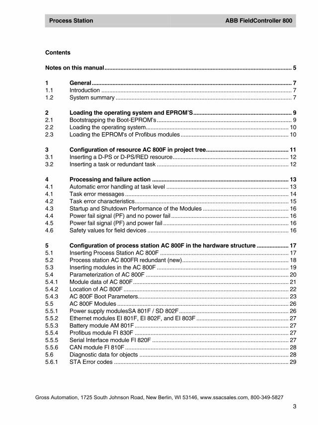
Contents
Notes on this manual...................................................................................................................... 5
1 General.............................................................................................................................. 71.1 Introduction ........................................................................................................................ 71.2 System summary ............................................................................................................... 7
2 Loading the operating system and EPROM’S.............................................................. 92.1 Bootstrapping the Boot-EPROM’s..................................................................................... 92.2 Loading the operating system.......................................................................................... 102.3 Loading the EPROM's of Profibus modules .................................................................... 10
3 Configuration of resource AC 800F in project tree.................................................... 113.1 Inserting a D-PS or D-PS/RED resource......................................................................... 123.2 Inserting a task or redundant task ................................................................................... 12
4 Processing and failure action ...................................................................................... 134.1 Automatic error handling at task level ............................................................................. 134.1 Task error messages ....................................................................................................... 144.2 Task error characteristics................................................................................................. 154.3 Startup and Shutdown Performance of the Modules ...................................................... 164.4 Power fail signal (PF) and no power fail .......................................................................... 164.5 Power fail signal (PF) and power fail ............................................................................... 164.6 Safety values for field devices ......................................................................................... 16
5 Configuration of process station AC 800F in the hardware structure .................... 175.1 Inserting Process Station AC 800F ................................................................................. 175.2 Process station AC 800FR redundant (new)................................................................... 185.3 Inserting modules in the AC 800F ................................................................................... 195.4 Parameterization of AC 800F .......................................................................................... 205.4.1 Module data of AC 800F.................................................................................................. 215.4.2 Location of AC 800F ........................................................................................................ 225.4.3 AC 800F Boot Parameters............................................................................................... 235.5 AC 800F Modules ............................................................................................................ 265.5.1 Power supply modulesSA 801F / SD 802F..................................................................... 265.5.2 Ethernet modules EI 801F, EI 802F, and EI 803F .......................................................... 275.5.3 Battery module AM 801F................................................................................................. 275.5.4 Profibus module FI 830F ................................................................................................. 275.5.5 Serial Interface module FI 820F ...................................................................................... 275.5.6 CAN module FI 810F ....................................................................................................... 285.6 Diagnostic data for objects .............................................................................................. 285.6.1 STA Error codes .............................................................................................................. 29
Gross Automation, 1725 South Johnson Road, New Berlin, WI 53146, www.ssacsales.com, 800-349-5827

Prozeßstation ABB FieldController 800
4
6 Commissioning of AC 800F ..........................................................................................306.1 Operating via resource AC 800F .....................................................................................306.2 Task ..................................................................................................................................326.2.1 Process image display .....................................................................................................336.3 Program list (PL)...............................................................................................................346.4 State displays in the project tree ......................................................................................346.4.1 Resource state displays ...................................................................................................356.4.2 Resource state diagram ...................................................................................................376.4.3 Task state displays...........................................................................................................386.4.4 Task state diagram...........................................................................................................396.4.5 Program list state displays ...............................................................................................396.5 State displayed in the hardware structure........................................................................406.5.1 State in the tree view........................................................................................................406.5.2 Module state in the system and station views .................................................................416.5.3 State of the basic unit.......................................................................................................426.5.4 Status of the FieldController modules..............................................................................42
7 Redundancy....................................................................................................................437.1 Network configuration in the hardware structure .............................................................437.2 Synchronization................................................................................................................447.3 Redundancy toggle ..........................................................................................................457.4 Redundancy criteria .........................................................................................................457.5 Status diagram of the active FieldController (Primary)....................................................467.6 States of the active FieldController (Primary) ..................................................................477.7 Status diagram of the passive FieldController (Secondary) ............................................487.8 States of the passive FieldController (Secondary) ..........................................................487.9 Technical data on Redundancy .......................................................................................497.10 Changing a Non-Redundant Process Station into a Redundant one..............................49
Gross Automation, 1725 South Johnson Road, New Berlin, WI 53146, www.ssacsales.com, 800-349-5827
Process Station ABB FieldController 800
5
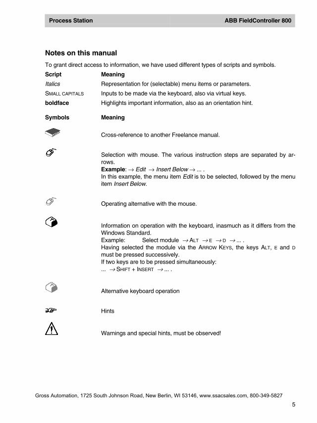
Notes on this manual
To grant direct access to information, we have used different types of scripts and symbols.
Script Meaning
Italics Representation for (selectable) menu items or parameters.
SMALL CAPITALS Inputs to be made via the keyboard, also via virtual keys.
boldface Highlights important information, also as an orientation hint.
Symbols Meaning
Cross-reference to another Freelance manual.
Selection with mouse. The various instruction steps are separated by ar-rows.Example: → Edit → Insert Below → ... .In this example, the menu item Edit is to be selected, followed by the menuitem Insert Below.
Operating alternative with the mouse.
Information on operation with the keyboard, inasmuch as it differs from theWindows Standard.Example: Select module → ALT → E → D → ... .Having selected the module via the ARROW KEYS, the keys ALT, E and D
must be pressed successively.If two keys are to be pressed simultaneously:... → SHIFT + INSERT → ... .
Alternative keyboard operation
Hints
Warnings and special hints, must be observed!
Gross Automation, 1725 South Johnson Road, New Berlin, WI 53146, www.ssacsales.com, 800-349-5827

Gross Automation, 1725 South Johnson Road, New Berlin, WI 53146, www.ssacsales.com, 800-349-5827
Process Station ABB FieldController 800
7
1 General
1.1 Introduction
The ABB FieldController 800 is an Industrial IT Controller which, along with its add-ons, offers astraightforward and successful way into Fieldbus systems.
• Reading in and expanding configuration information from new field devices• Configuring devices via parameter-definition masks and using pre-defined I/O structures• Showing bus cycle times and diagnostic data from devices• Searching the bus for subscribers with unknown device addresses• Removing individual devices from the cyclic communication• Incorporating new devices without having to initialize the bus line
You can perform the necessary configuration and commissioning tasks from your PC using just asingle software tool: Diagnoses are performed in graphic interfaces. In addition the EngineeringSoftware offers extensive diagnosis options right down to the field devices.Your automation task is configured in graphic editors as per IEC 61131-3 and loaded online intothe AC 800F.So that you can easily display and operate your process, high-performance display packagessuch as DigiVis and Maestro NT are also available for the AC 800F.
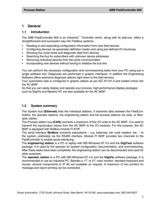
1.2 System summary
The System bus (Ethernet) links the individual stations. It transmits data between the FieldCon-trollers, the operator stations, the engineering station and the process stations via coax. or fiber-optic cables.The Process station bus (CAN) connects a maximum of five I/O units to the AC 800F. It is used totransmit the input/output values from the AC 800F to the I/O modules. For this purpose, the AC800F is equipped with fieldbus module FI 810F.The serial interface Modbus connects subsystems – e.g. balances, bar code readers, etc. – tothe system, preferably via the RS485 interface. Module FI 820F provides two channels to theFieldController to enable serial interfacing.The engineering station is a PC or laptop with MS-Windows NT 4.0 and the DigiTool softwarepackage. It is used by the operator for system configuration, documentation, and commissioning.After these tasks have been completed, the engineering station can be disconnected and used forother purposes.The operator station is a PC with MS-Windows NT 4.0 and the DigiVis software package. It isrecommended to use an industrial PC. Besides a 17" or 21" color monitor, standard keyboard andmouse, several components to IP 65 are available on request. A maximum of two printers formessage and report printing can be connected.
Gross Automation, 1725 South Johnson Road, New Berlin, WI 53146, www.ssacsales.com, 800-349-5827
Process Station ABB FieldController 800
8
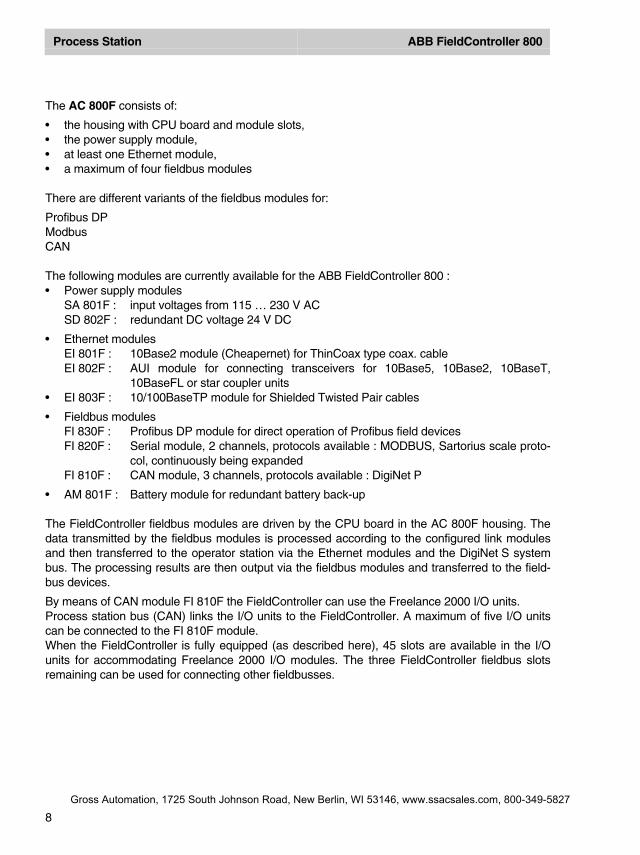
The AC 800F consists of:
• the housing with CPU board and module slots,• the power supply module,• at least one Ethernet module,• a maximum of four fieldbus modules
There are different variants of the fieldbus modules for:
Profibus DPModbusCAN
The following modules are currently available for the ABB FieldController 800 :• Power supply modules
SA 801F : input voltages from 115 … 230 V ACSD 802F : redundant DC voltage 24 V DC
• Ethernet modulesEI 801F : 10Base2 module (Cheapernet) for ThinCoax type coax. cableEI 802F : AUI module for connecting transceivers for 10Base5, 10Base2, 10BaseT,
10BaseFL or star coupler units• EI 803F : 10/100BaseTP module for Shielded Twisted Pair cables
• Fieldbus modulesFI 830F : Profibus DP module for direct operation of Profibus field devicesFI 820F : Serial module, 2 channels, protocols available : MODBUS, Sartorius scale proto-
col, continuously being expandedFI 810F : CAN module, 3 channels, protocols available : DigiNet P
• AM 801F : Battery module for redundant battery back-up
The FieldController fieldbus modules are driven by the CPU board in the AC 800F housing. Thedata transmitted by the fieldbus modules is processed according to the configured link modulesand then transferred to the operator station via the Ethernet modules and the DigiNet S systembus. The processing results are then output via the fieldbus modules and transferred to the field-bus devices.
By means of CAN module FI 810F the FieldController can use the Freelance 2000 I/O units.Process station bus (CAN) links the I/O units to the FieldController. A maximum of five I/O unitscan be connected to the FI 810F module.When the FieldController is fully equipped (as described here), 45 slots are available in the I/Ounits for accommodating Freelance 2000 I/O modules. The three FieldController fieldbus slotsremaining can be used for connecting other fieldbusses.
Gross Automation, 1725 South Johnson Road, New Berlin, WI 53146, www.ssacsales.com, 800-349-5827
Process Station ABB FieldController 800
9
2 Loading the operating system and EPROM’S
2.1 Bootstrapping the Boot-EPROM’s
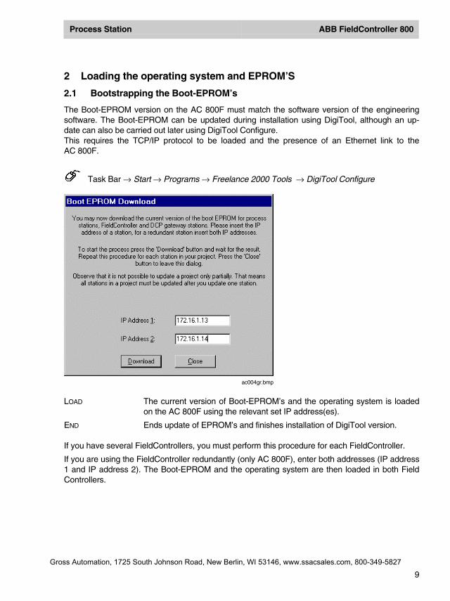
The Boot-EPROM version on the AC 800F must match the software version of the engineeringsoftware. The Boot-EPROM can be updated during installation using DigiTool, although an up-date can also be carried out later using DigiTool Configure.This requires the TCP/IP protocol to be loaded and the presence of an Ethernet link to theAC 800F.
Task Bar → Start → Programs → Freelance 2000 Tools → DigiTool Configure
LOAD The current version of Boot-EPROM’s and the operating system is loadedon the AC 800F using the relevant set IP address(es).
END Ends update of EPROM’s and finishes installation of DigiTool version.
If you have several FieldControllers, you must perform this procedure for each FieldController.
If you are using the FieldController redundantly (only AC 800F), enter both addresses (IP address1 and IP address 2). The Boot-EPROM and the operating system are then loaded in both FieldControllers.
ac004gr.bmp
Gross Automation, 1725 South Johnson Road, New Berlin, WI 53146, www.ssacsales.com, 800-349-5827
Process Station ABB FieldController 800
10
2.2 Loading the operating system
The operating system can be loaded by bootstrap via the system bus into the station.
Requirement It is necessary that no operating system be present in the FieldController(RUN/STOP Led off). If necessary a general reset must be performed be-forehand.
The initial loading of the operating system (bootstrapping) takes place automatically when aboot EPROM is first loaded via load boot EPROM. It can also, however, be carried outseparately from user program loading after initalize all. It is not necessary to load the op-erating system into the Secondary, as loading the Boot-EPROM means that the operatingsystem has already been loaded and it is not deleted in the Secondary when a general re-set is carried out.
2.3 Loading the EPROM's of Profibus modules
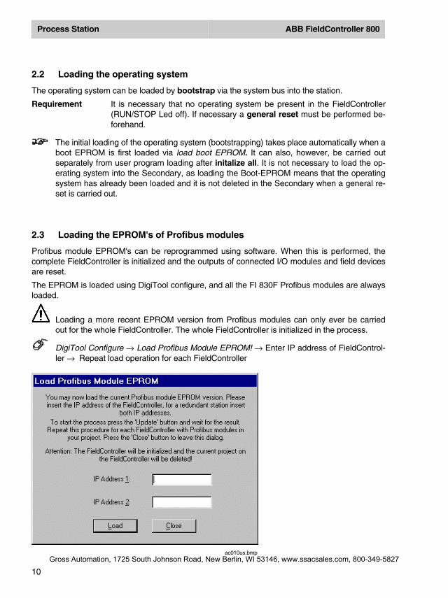
Profibus module EPROM's can be reprogrammed using software. When this is performed, thecomplete FieldController is initialized and the outputs of connected I/O modules and field devicesare reset.
The EPROM is loaded using DigiTool configure, and all the FI 830F Profibus modules are alwaysloaded.
Loading a more recent EPROM version from Profibus modules can only ever be carriedout for the whole FieldController. The whole FieldController is initialized in the process.
DigiTool Configure → Load Profibus Module EPROM! → Enter IP address of FieldControl-ler → Repeat load operation for each FieldController
ac010us.bmpGross Automation, 1725 South Johnson Road, New Berlin, WI 53146, www.ssacsales.com, 800-349-5827
Process Station ABB FieldController 800
11
3 Configuration of resource AC 800F in project tree
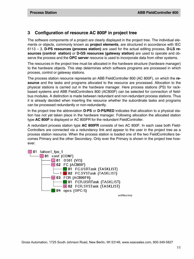
The software components of a project are clearly displayed in the project tree. The individual ele-ments or objects, commonly known as project elements, are structured in accordance with IEC6113 – 3. D-PS resources (process station) are used for the actual editing process, D-LS re-sources (control station) or D-GS resources (gateway station) are used to operate and ob-serve the process and the OPC server resource is used to incorporate data from other systems.
The resources in the project tree must be allocated in the hardware structure (hardware manager)to the hardware objects. This step determines which software programs are processed in whichprocess, control or gateway stations.
The process station resource represents an ABB FieldController 800 (AC 800F), on which the re-source and the tasks and programs allocated to the resource are processed. Allocation to thephysical stations is carried out in the hardware manager. Here process stations (PS) for rack-based systems and ABB FieldControllers 800 (AC800F) can be selected for connection of field-bus modules. A distinction is made between redundant and non-redundant process stations. Thusit is already decided when inserting the resource whether the subordinate tasks and programscan be processed redundantly or non-redundantly.
In the project tree the abbreviation D-PS or D-PS/RED indicates that allocation to a physical sta-tion has not yet taken place in the hardware manager. Following allocation the allocated stationtype AC 800F is displayed or AC 800FR for the redundant FieldController.
A redundant process station type AC 800FR consists of two AC 800F. In each case both Field-Controllers are connected via a redundancy link and appear to the user in the project tree as aprocess station resource. When the process station is loaded one of the two FieldControllers be-comes Primary and the other Secondary. Only ever the Primary is shown in the project tree how-ever.
ac008us.bmp
Gross Automation, 1725 South Johnson Road, New Berlin, WI 53146, www.ssacsales.com, 800-349-5827
Process Station ABB FieldController 800
12
3.1 Inserting a D-PS or D-PS/RED resource
Select target position of new process station
→ insert overa new process station can be inserted over the selected object
→ Insert undera new process station can be inserted under the selected object
→ Insert next levela new process station can be inserted one level deeper
The target position can be located at the next level below the configurationelement or (only in the case of next level insertion) on the configuration itself.
→ on target position and press left mouse button → OK
3.2 Inserting a task or redundant task
In the process station the actual programs run into the task. The programs are edited either usingInstruction Lists or Sequential Function Chart.
A redundant task has so-called redundancy data. These are data of the process image and of thefunction blocks for which a data adjustment is performed after each cycle. This ensures that a re-dundancy toggle can take place at any point in time.So that the data of a redundant task are redundancy-capable, all variables of a redundant taskmust be written in process image mode.
Not only the redundant task (TASK/RED), but also tasks of the previous type (TASK) can be con-figured under the redundant resources. Thus only those functions of the user program which alsoactually have to be redundant need to be configured redundantly within a redundant resource.
Gross Automation, 1725 South Johnson Road, New Berlin, WI 53146, www.ssacsales.com, 800-349-5827

Process Station ABB FieldController 800
13
4 Processing and failure action
4.1 Automatic error handling at task level
Error handling at task level is described in the flow chart (page 39).
When an error is identified in a user program, an error task is executed once. The error- task isthe highest priority task (priority 100) of a resource and is used to handle errors in user programsby user programs. In the case of non-recoverable errors, the error-generating task changes to theunrunnable state; in the case of recoverable errors it is possible to continue running the error-generating task, provided the automatic error correction for the D-PS resource is switched on.Owing to its high priority it cannot be interrupted by other tasks. Execution of the error task can besuppressed.
Error handling at task level is switched on by default but can be deactivated in the resource con-figuration (see Engineering Manual, System Configuration, Project tree). When deactivated,an error causes the task to change to the unrunnable state, even if the error is recoverable. Theerror appears in text form in the task header and the object number of the faulty project object isalso displayed.
If automatic error handling is active and a recoverable error is detected, the affected task remainsin the running state. In this case, the error condition is ascertainable only by evaluation of thesystem variables.
Each runtime error detected during execution of a command results in an entry recording thecause and location of the error in system variables specially predefined for error handling. Thecause of the error, e.g. 4 for UINT div. by 0, is saved in the variable “ErrorNo”. The variable “Er-rorProgra” is written with the object number of the program or function block that caused the error.Furthermore, the object number of the affected task is saved in the variable “ErrorTask,” but onlydisplayed in the task header if error handling is deactivated. The affected object can then be lo-calized in the object list with its name, state, type and position in the project tree. If the affectedtask, the one which triggered the error, is not the error-handling task, the error-handling task itselfis now triggered. Error handling specific to the cause of the error and/or its location can be un-dertaken in this task, with the aid of the system variables.
If an error should occur in the error-handling task itself, the error-handing task is signaled as un-runnable.
See also Engineering Manual, IEC 61131-3 Programming, Variables, System Variables.
Gross Automation, 1725 South Johnson Road, New Berlin, WI 53146, www.ssacsales.com, 800-349-5827
Process Station ABB FieldController 800
14
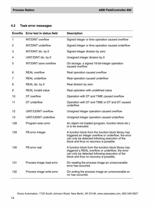
4.2 Task error messages
ErrorNo Error text in status field Description
1 INT/DINT overflow Signed integer or time operation caused overflow
2 INT/DINT underflow Signed integer or time operation caused underflow
3 INT/DINT div. by 0 Signed integer division by zero
4 UINT/DINT div. by 0 Unsigned integer division by 0
5 INT/DINT save overflow On storage, a signed 16-bit-integer operationcaused overflow
6 REAL overflow Real operation caused overflow
7 REAL underflow Real operation caused underflow
8 REAL div. by 0 Real division by zero
9 REAL invalid value Real operation with undefined value
10 DT overflow Operation with DT and TIME caused overflow
11 DT underflow Operation with DT and TIME or DT and DT causedunderflow
12 UINT/UDINT overflow Unsigned integer operation caused overflow
13 UINT/UDINT underflow Unsigned integer operation caused underflow
128 Program exec error An object not loaded (program, function block etc.)is to be executed
129 FB error integer A function block from the function block library hastriggered an integer overflow or underflow, the errorcan only be detected following execution of theblock and thus no recovery is possible.
130 FB error real A function block from the function block library hastriggered a REAL overflow or underflow, the errorcan only be detected following execution of theblock and thus no recovery is possible.
131 Process image read error On reading the process image an unrecoverableerror has occurred
132 Process image write error On writing the process image an unrecoverable er-ror has occurred.
Gross Automation, 1725 South Johnson Road, New Berlin, WI 53146, www.ssacsales.com, 800-349-5827
Process Station ABB FieldController 800
15
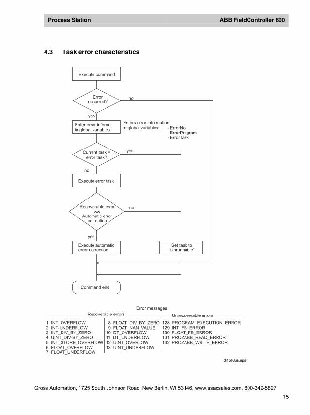
4.3 Task error characteristics
8 FLOAT_DIV_BY_ZERO9 FLOAT_NAN_VALUE
10 DT_OVERFLOW11 DT_UNDERFLOW12 UINT_OVERLOW13 UINT_UNDERFLOW
128 PROGRAM_EXECUTION_ERROR129 INT_FB_ERROR130 FLOAT_FB_ERROR131 PROZABB_READ_ERROR132 PROZABB_WRITE_ERROR
1 INT_OVERFLOW2 INT-UNDERFLOW3 INT_DIV_BY_ZERO4 UINT_DIV-BY_ZERO5 INT_STORE_OVERFLOW6 FLOAT_OVERFLOW7 FLOAT_UNDERFLOW
Execute command
Erroroccurred?
no
no
no
yes
yes
yes
Enter error inform.in global variables
Enters error informationin global variables: - ErrorNo
- ErrorProgram- ErrorTask
Current task =error task?
Execute error task
Recoverable error&&
Automatic errorcorrection
Execute automaticerror correction
Set task to“Unrunnable”
Command end
Error messages
Unrecoverable errorsRecoverable errors
di1503us.eps
Gross Automation, 1725 South Johnson Road, New Berlin, WI 53146, www.ssacsales.com, 800-349-5827
Process Station ABB FieldController 800
16
4.4 Startup and Shutdown Performance of the Modules
A signal for connection monitoring is continuously exchanged between I/O modules and theFieldController CPU of the process station or FieldController. If this signal does not appear formore than 250 ms (for 500 kbit/s) and/or 1,25 s (for 100 kbit/s ) both sides detect the interruptionof the connection. The FieldController sends a system message to the operator station and theoutput modules adopt the safety values. Dependent on the requests of the process the safetyvalues can configured as "Hold the last value" or to a particular value/state.
A cold process station or FieldController start always leads to output of the safety values.
For "Load whole station" and at resource Initialization/Overall reset, the output levels of the outputmodules go to zero current.
4.5 Power fail signal (PF) and no power fail
PF < 15 ms While PF signal is active, the CPU module of the process station or theFieldController does not communicate actual values; I/O modules maintainthe last values.
PF > 15 ms I/O modules maintain the last values until they have recognized the inter-rupted connection with the CPU module or FieldController; they then adoptthe configured safety values. Safety values are maintained until the CPUmodule or FieldController has executed a warm start and sends new valuesto the I/O modules.
4.6 Power fail signal (PF) and power fail
I/O modules maintain the last values until they have recognized the connection interruption andthen adopt safety values until the CPU module or FieldController sends actual values after restart.In the case of power fail of the I/O module, output levels adopt zero voltage and/or zero current.
After voltage return I/O modules only change their output level when the CPU module or Field-Controller communicates actual values. Analog output modules are an exception. They hold thelast values as long as external voltage supply does not fail. Outputs are only deenergized if theCPU module or FieldController is supplied with voltage.
4.7 Safety values for field devices
The cyclic exchange of data between Profibus master and the connected slaves is monitored.When the cyclic exchange of data is interrupted, safety values can be assumed. The definition ofsafety values for output channels is vendor-specific. For input channels, depending on the re-quirements of the process, the safety values can be configured to “Hold last value” or a specificvalue or state.
A possible power failure can be evaluated using a system variable and utilized in the userprogram.
Gross Automation, 1725 South Johnson Road, New Berlin, WI 53146, www.ssacsales.com, 800-349-5827
Process Station ABB FieldController 800
17
5 Configuration of process station AC 800F in the hardware structure
Within the hardware structure the resources defined in the project tree are allocated to the hard-ware actually required. The D-PS resource stands for a process station.
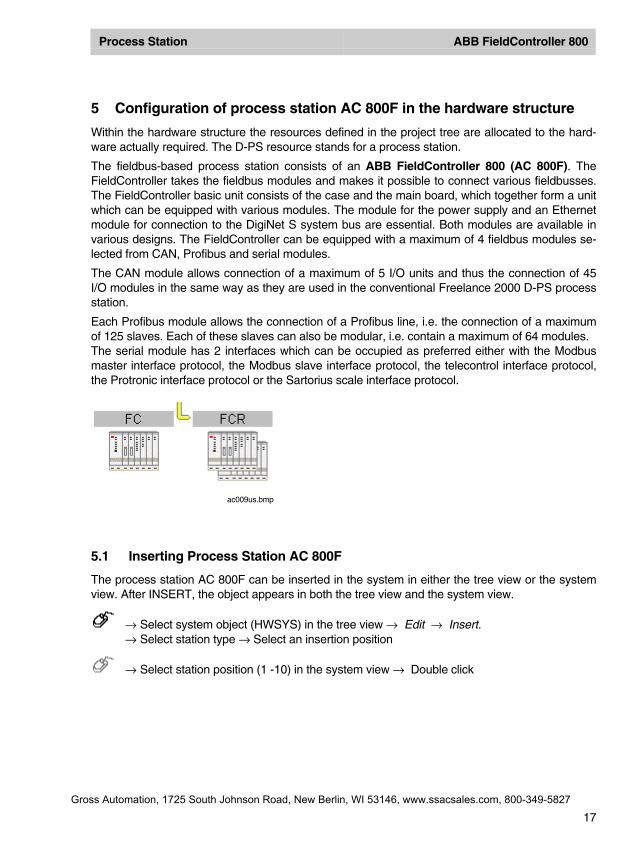
The fieldbus-based process station consists of an ABB FieldController 800 (AC 800F). TheFieldController takes the fieldbus modules and makes it possible to connect various fieldbusses.The FieldController basic unit consists of the case and the main board, which together form a unitwhich can be equipped with various modules. The module for the power supply and an Ethernetmodule for connection to the DigiNet S system bus are essential. Both modules are available invarious designs. The FieldController can be equipped with a maximum of 4 fieldbus modules se-lected from CAN, Profibus and serial modules.
The CAN module allows connection of a maximum of 5 I/O units and thus the connection of 45I/O modules in the same way as they are used in the conventional Freelance 2000 D-PS processstation.
Each Profibus module allows the connection of a Profibus line, i.e. the connection of a maximumof 125 slaves. Each of these slaves can also be modular, i.e. contain a maximum of 64 modules.The serial module has 2 interfaces which can be occupied as preferred either with the Modbusmaster interface protocol, the Modbus slave interface protocol, the telecontrol interface protocol,the Protronic interface protocol or the Sartorius scale interface protocol.
5.1 Inserting Process Station AC 800F
The process station AC 800F can be inserted in the system in either the tree view or the systemview. After INSERT, the object appears in both the tree view and the system view.
→ Select system object (HWSYS) in the tree view → Edit → Insert.→ Select station type → Select an insertion position
→ Select station position (1 -10) in the system view → Double click
ac009us.bmp
Gross Automation, 1725 South Johnson Road, New Berlin, WI 53146, www.ssacsales.com, 800-349-5827
Process Station ABB FieldController 800
18
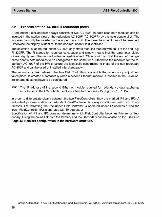
5.2 Process station AC 800FR redundant (new)
A redundant FieldController always consists of two AC 800F. In each case both modules can beinserted in the station view of the redundant AC 800F (AC 800FR) by a simple double click. Themodules can only be inserted in the upper basic unit. The lower basic unit cannot be selected.Otherwise the display is identical to the non-redundant FieldController.
The selection list of the redundant AC 800F only offers modules marked with an R at the end, e.g.FI 830FR. The R stands for redundancy-capable and simply means that the parameter dialogdiffers slightly from the non-redundancy-capable object. Objects with an R at the end of the typename enable both modules to be configured at the same time. Otherwise the modules for the re-dundant AC 800F of the HW structure are identically constructed to those of the non-redundantAC 800F and can be used or installed interchangeably.
The redundancy link between the two FieldControllers, via which the redundancy adjustmenttakes place, is created automatically when a second Ethernet module is inserted in the FieldCon-troller, and does not have to be configured.
The IP address of the second Ethernet module required for redundancy data exchangemust be set in the HW of both FieldControllers to IP address 15 (e.g. 172.16..1.15).
In order to differentiate clearly between the two FieldControllers, they are marked IP1 and IP2. Aredundant process station or redundant FieldController is always configured with two IP ad-dresses, IP1 indicating that the upper FieldController is operated under IP address 1 and thelower FieldController IP2 is operated with IP address 2.Specification of IP1 and IP2 does not determine which FieldController becomes Primary or Sec-ondary. Using the online link both the Primary and the Secondary can be located on top. See alsoPage 43, Network configuration in the hardware structure.
Gross Automation, 1725 South Johnson Road, New Berlin, WI 53146, www.ssacsales.com, 800-349-5827
Process Station ABB FieldController 800
19
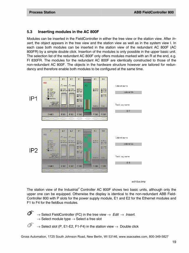
5.3 Inserting modules in the AC 800F
Modules can be inserted in the FieldController in either the tree view or the station view. After In-sert, the object appears in the tree view and the station view as well as in the system view I. Ineach case both modules can be inserted in the station view of the redundant AC 800F (AC800FR) by a simple double click. Insertion of the modules is only possible in the upper basic unit.The selection list of the redundant AC 800F only offers modules marked with an R at the end, e.g.FI 830FR. The modules for the redundant AC 800F are identically constructed to those of thenon-redundant AC 800F. The objects in the hardware structure however are tailored for redun-dancy and therefore enable both modules to be configured at the same time.
The station view of the IndustrialIT Controller AC 800F shows two basic units, although only theupper one can be equipped. Otherwise the display is identical to the non-redundant ABB Field-Controller 800 with P slots for the power supply module, E1 and E2 for the Ethernet modules andF1 to F4 for the fieldbus modules.
→ Select FieldController (FC) in the tree view → Edit → Insert.→ Select module type → Select a free slot
→ Select slot (P, E1-E2, F1-F4) in the station view → Double click
ac012us.bmp
Gross Automation, 1725 South Johnson Road, New Berlin, WI 53146, www.ssacsales.com, 800-349-5827
Process Station ABB FieldController 800
20
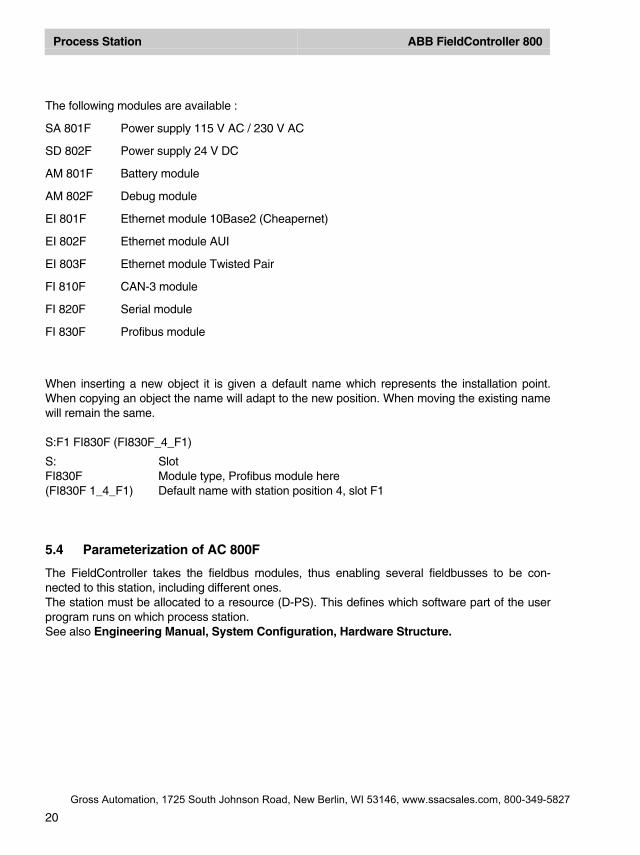
The following modules are available :
SA 801F Power supply 115 V AC / 230 V AC
SD 802F Power supply 24 V DC
AM 801F Battery module
AM 802F Debug module
EI 801F Ethernet module 10Base2 (Cheapernet)
EI 802F Ethernet module AUI
EI 803F Ethernet module Twisted Pair
FI 810F CAN-3 module
FI 820F Serial module
FI 830F Profibus module
When inserting a new object it is given a default name which represents the installation point.When copying an object the name will adapt to the new position. When moving the existing namewill remain the same.
S:F1 FI830F (FI830F_4_F1)
S: SlotFI830F Module type, Profibus module here(FI830F 1_4_F1) Default name with station position 4, slot F1
5.4 Parameterization of AC 800F
The FieldController takes the fieldbus modules, thus enabling several fieldbusses to be con-nected to this station, including different ones.The station must be allocated to a resource (D-PS). This defines which software part of the userprogram runs on which process station.See also Engineering Manual, System Configuration, Hardware Structure.
Gross Automation, 1725 South Johnson Road, New Berlin, WI 53146, www.ssacsales.com, 800-349-5827
Process Station ABB FieldController 800
21
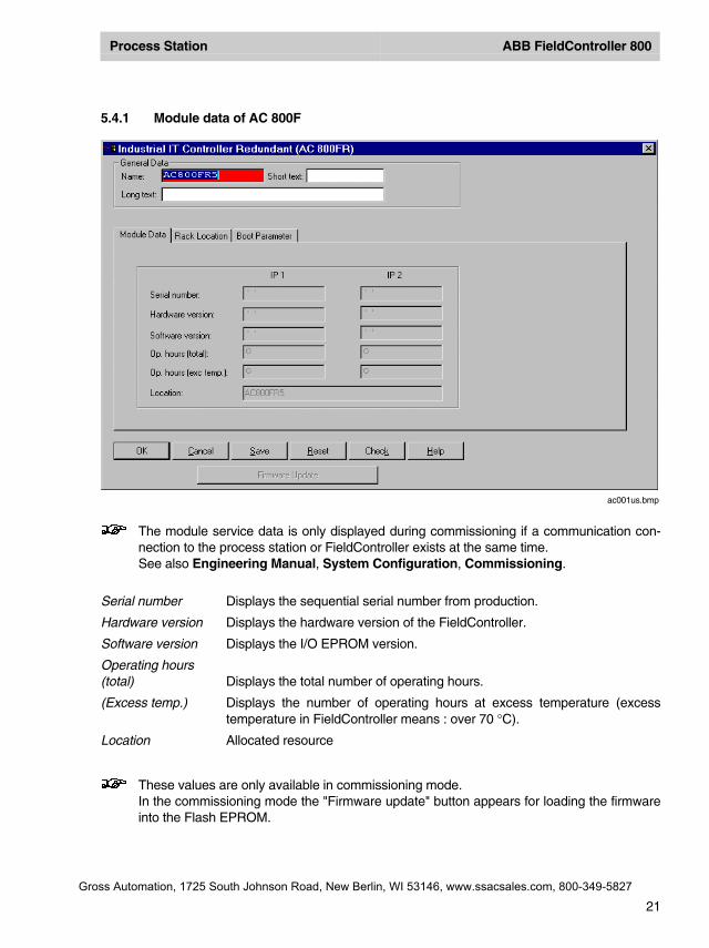
5.4.1 Module data of AC 800F
The module service data is only displayed during commissioning if a communication con-nection to the process station or FieldController exists at the same time.See also Engineering Manual, System Configuration, Commissioning.
Serial number Displays the sequential serial number from production.
Hardware version Displays the hardware version of the FieldController.
Software version Displays the I/O EPROM version.
Operating hours(total) Displays the total number of operating hours.
(Excess temp.) Displays the number of operating hours at excess temperature (excesstemperature in FieldController means : over 70 °C).
Location Allocated resource
These values are only available in commissioning mode.In the commissioning mode the "Firmware update" button appears for loading the firmwareinto the Flash EPROM.
ac001us.bmp
Gross Automation, 1725 South Johnson Road, New Berlin, WI 53146, www.ssacsales.com, 800-349-5827
Process Station ABB FieldController 800
22
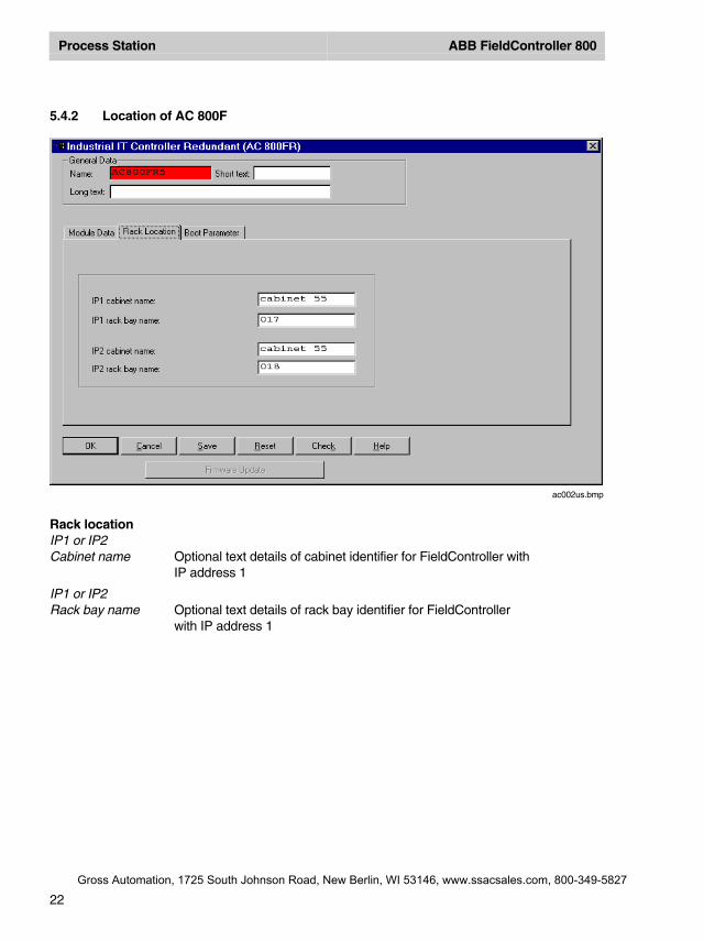
5.4.2 Location of AC 800F
Rack locationIP1 or IP2Cabinet name Optional text details of cabinet identifier for FieldController with
IP address 1
IP1 or IP2Rack bay name Optional text details of rack bay identifier for FieldController
with IP address 1
ac002us.bmp
Gross Automation, 1725 South Johnson Road, New Berlin, WI 53146, www.ssacsales.com, 800-349-5827

Process Station ABB FieldController 800
23
5.4.3 AC 800F Boot Parameters
Memory These parameters affect the allocation of memory within the process sta-tion. When there are an extremely large number of objects in the FieldCon-troller, errors may occur on loading the objects; these settings may be al-tered to try to make the project loadable.
Under normal circumstances the boot parameters should not bechanged. If they are changed, then the resource is initialized whenthe modified boot parameters are loaded.Attention should also be paid to the system variables PRAM_Freeand RAM_Free after loading. If the variable PRAM_Free has avalue of 0, then the value of PRAM_Size must be increased; if thevariable RAM_Free is set to 0, then both PRAM_Size and themaximum number of objects must be reduced.
The AC 800F has 4 Mbytes memory. The memory is subdivided into differ-ent parts as listed below.
The following are filed in the Flash memory :• Operating system• Boot-EPROM
ac003us.bmp
Gross Automation, 1725 South Johnson Road, New Berlin, WI 53146, www.ssacsales.com, 800-349-5827
Process Station ABB FieldController 800
24
The RAM memory is divided into sections ::• object directory• PRAM• redundancy memory• object data• communication management
The memory for the objects, memory for PRAM and, if available, memoryfor redundancy can be adjusted in the boot parameters of the resource.Any surplus memory is made available in RAM. There is no absolute limiton the memory ranges that can be set. Whenever a limit is reached, it canbe changed. This results in a reduction of free RAM.
To ascertain a suitable value for PRAM, current values can be read incommissioning mode. These values are shown in the following system vari-ables:
PS.PRAM_SIZE The PRAM size set in the boot parametersPS.PRAM_FREE The proportion of free PRAMPS.RAM_SIZE The amount of RAM in usePS.RAM_FREE The proportion of free RAM
Max. no.of objects The maximum number of objects that can be loaded on the resource
Configurationdate (PRAM) Memory size in Kbytes that is reserved for the configuration data. This
memory area is cold-start resistant.
Configuredredundancy memory Memory size in Kbytes that is reserved for the transfer of redundancy data.
Max. redundancymemory required Maximum size of memory required by the project for transfer of redundancy
data.
The redundancy memory is only shown in redundant and plausibleprocess stations.
Tasks Communication management parameters. Every communication link re-quires internal system resources such as additional memory or system ob-jects.
Network buffer Area of memory in Kbytes that is reserved for the communication links.
Interfaceobjects Maximum number of objects that can be reserved for interfaces.
Gross Automation, 1725 South Johnson Road, New Berlin, WI 53146, www.ssacsales.com, 800-349-5827
Process Station ABB FieldController 800
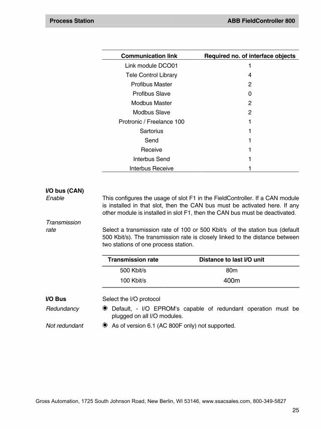
25
Communication link Required no. of interface objects
Link module DCO01 1
Tele Control Library 4
Profibus Master 2
Profibus Slave 0
Modbus Master 2
Modbus Slave 2
Protronic / Freelance 100 1
Sartorius 1
Send 1
Receive 1
Interbus Send 1
Interbus Receive 1
I/O bus (CAN)Enable This configures the usage of slot F1 in the FieldController. If a CAN module
is installed in that slot, then the CAN bus must be activated here. If anyother module is installed in slot F1, then the CAN bus must be deactivated.
Transmissionrate Select a transmission rate of 100 or 500 Kbit/s of the station bus (default
500 Kbit/s). The transmission rate is closely linked to the distance betweentwo stations of one process station.
Transmission rate Distance to last I/O unit
500 Kbit/s 80m
100 Kbit/s 400m
I/O Bus Select the I/O protocol
Redundancy Default, - I/O EPROM’s capable of redundant operation must beplugged on all I/O modules.
Not redundant As of version 6.1 (AC 800F only) not supported.
Gross Automation, 1725 South Johnson Road, New Berlin, WI 53146, www.ssacsales.com, 800-349-5827
Process Station ABB FieldController 800
26
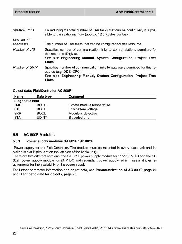
System limits By reducing the total number of user tasks that can be configured, it is pos-sible to gain extra memory (approx. 12.5 Kbytes per task).
Max. no. ofuser tasks The number of user tasks that can be configured for this resource.
Number of VIS Specifies number of communication links to control stations permitted forthis resource (Digivis).See also Engineering Manual, System Configuration, Project Tree,Links
Number of GWY Specifies number of communication links to gateways permitted for this re-source (e.g. DDE, OPC).See also Engineering Manual, System Configuration, Project Tree,Links
Object data: FieldController AC 800F
Name Data type CommentDiagnostic dataTMP BOOL Excess module temperatureBTL BOOL Low battery voltageERR BOOL Module is defectiveSTA UDINT Bit-coded error
5.5 AC 800F Modules
5.5.1 Power supply modules SA 801F / SD 802F
Power supply for the FieldController. The module must be mounted in every basic unit and in-stalled in slot P (first slot on the left side of the basic unit).There are two different versions, the SA 801F power supply module for 115/230 V AC and the SD802F power supply module for 24 V DC and redundant power supply, which meets stricter re-quirements for the availability of the power supply.
For further parameter information and object data, see Parameterization of AC 800F, page 20and Diagnostic data for objects, page 28.
Gross Automation, 1725 South Johnson Road, New Berlin, WI 53146, www.ssacsales.com, 800-349-5827
Process Station ABB FieldController 800
27
5.5.2 Ethernet modules EI 801F, EI 802F, and EI 803F
Ethernet connection module of the FieldController. The module must be mounted in every basicunit and installed in slot E1 or E2 (second and third slots on the left side of the basic unit).There are three different variants : Ethernet module EI 801F with 10Base2 (Cheapernet or BNC),Ethernet module EI 802F with AUI connection and Ethernet module EI 803F with Twisted Pairconnection.
For further parameter information and object data, see Parameterization of AC 800F, page 20and Diagnostic data for objects, page 28.
5.5.3 Battery module AM 801F
Battery module of the FieldController. The module can be mounted as an add-on in every basicunit and is used for redundant battery back-up of the internal memory (RAM). The module mustbe installed in slot E1 or E2 (second and third slots on the left side of the basic unit).
For further parameter information and object data, see Parameterization of AC 800F, page 20and Diagnostic data for objects, page 28.
5.5.4 Profibus module FI 830F
Profibus module of the FieldController. Each Profibus module allows the connection of a Profibusline, i.e. the connection of a maximum of 125 slaves. Each of these slaves may also be modular,i.e. may contain a maximum of 64 modules. The module may be installed in slots F1 to F4.
For further parameter information and object data, see Parameterization of AC 800F, page 20and Diagnostic data for objects, page 28.
The software version of the EPROM on the Profibus module can be updated via the Digi-Tool Configure Dialog. See Engineering Manual, System Configuration, InstallationDigiTool, Installation Adjustment.
5.5.5 Serial Interface module FI 820F
Serial interface module of the FieldController. The serial module has 2 interfaces which can beequipped as preferred by the Modbus master interface protocol, Modbus slave interface protocol,telecontrol interface protocol, Protronic interface protocol or Sartorius scale interface protocol.Below the serial module, the interface objects can be configured. The module itself can be in-stalled in slots F1 to F4..
For further parameter information and object data, see Parameterization of AC 800F, page 20and Diagnostic data for objects, page 28.
Gross Automation, 1725 South Johnson Road, New Berlin, WI 53146, www.ssacsales.com, 800-349-5827
Process Station ABB FieldController 800
28
5.5.6 CAN module FI 810F
CAN module of the FieldController. The CAN module allows the connection of a maximum of 5I/O units and thus the connection of 45 I/O modules in the way in which they are also used in theconventional Freelance 2000 D-PS process station. Below the CAN module, a CAN master mustbe configured.
For further parameter information and object data, see Parameterization of AC 800F, page 20and Diagnostic data for objects, page 28.
For each FieldController, it is possible to connect only one station bus (CAN) line withmaximum 5 racks. The slot of the FI 820F module is preset to F1 and cannot be changed.If a CAN module is installed in slot F1 of the FieldController, then the CAN bus must be ac-tivated in the boot parameters of the resource. If a different module is installed in slot F1,the CAN bus must be deactivated.
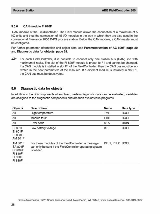
5.6 Diagnostic data for objects
In addition to the I/O components of an object, certain diagnostic data can be evaluated; variablesare assigned to the diagnostic components and are then evaluated in programs.
Objects Description Name Data type
All High temperature TMP BOOL
All Module fault ERR BOOL
All Error code STA UDINT
EI 801FEI 801FEI 803F,AM 801F
Low battery voltage BTL BOOL
AM 801FSA 801FSD 802FFI 810FFI 820FFI 830F
For these modules of the FieldController, a messagecan only be sent if the FieldController operating systemis loaded.
PFL1, PFL2 BOOL
Gross Automation, 1725 South Johnson Road, New Berlin, WI 53146, www.ssacsales.com, 800-349-5827
Process Station ABB FieldController 800
29
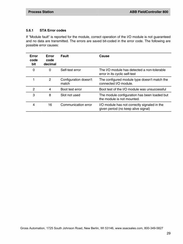
5.6.1 STA Error codes
If "Module fault" is reported for the module, correct operation of the I/O module is not guaranteedand no data are transmitted. The errors are saved bit-coded in the error code. The following arepossible error causes:
Errorcodebit
Errorcode
decimal
Fault Cause
0 0 Self-test error The I/O module has detected a non-tolerableerror in its cyclic self-test
1 2 Configuration doesn'tmatch
The configured module type doesn't match theconnected I/O module.
2 4 Boot test error Boot test of the I/O module was unsuccessful
3 8 Slot not used The module configuration has been loaded butthe module is not mounted.
4 16 Communication error I/O module has not correctly signaled in thegiven period (no keep alive signal)
Gross Automation, 1725 South Johnson Road, New Berlin, WI 53146, www.ssacsales.com, 800-349-5827
Process Station ABB FieldController 800
30
6 Commissioning of AC 800F
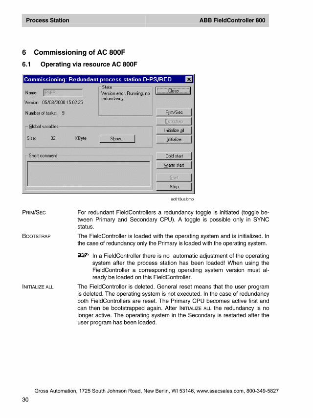
6.1 Operating via resource AC 800F
PRIM/SEC For redundant FieldControllers a redundancy toggle is initiated (toggle be-tween Primary and Secondary CPU). A toggle is possible only in SYNCstatus.
BOOTSTRAP The FieldController is loaded with the operating system and is initialized. Inthe case of redundancy only the Primary is loaded with the operating system.
In a FieldController there is no automatic adjustment of the operatingsystem after the process station has been loaded! When using theFieldController a corresponding operating system version must al-ready be loaded on this FieldController.
INITIALIZE ALL The FieldController is deleted. General reset means that the user programis deleted. The operating system is not executed. In the case of redundancyboth FieldControllers are reset. The Primary CPU becomes active first andcan then be bootstrapped again. After INITIALIZE ALL the redundancy is nolonger active. The operating system in the Secondary is restarted after theuser program has been loaded.
ac013us.bmp
Gross Automation, 1725 South Johnson Road, New Berlin, WI 53146, www.ssacsales.com, 800-349-5827
Process Station ABB FieldController 800
31
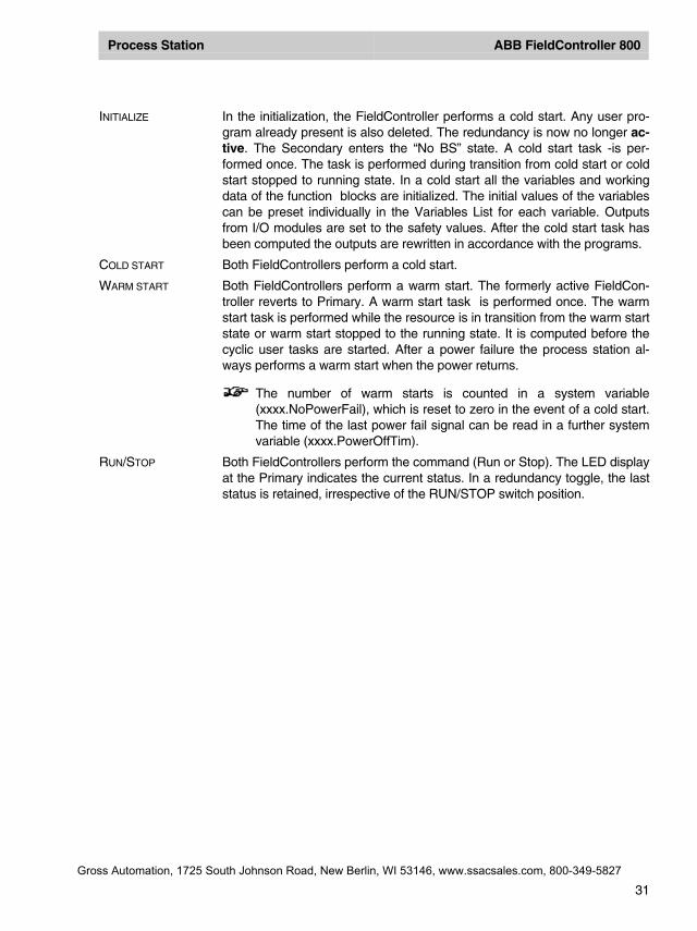
INITIALIZE In the initialization, the FieldController performs a cold start. Any user pro-gram already present is also deleted. The redundancy is now no longer ac-tive. The Secondary enters the “No BS” state. A cold start task -is per-formed once. The task is performed during transition from cold start or coldstart stopped to running state. In a cold start all the variables and workingdata of the function blocks are initialized. The initial values of the variablescan be preset individually in the Variables List for each variable. Outputsfrom I/O modules are set to the safety values. After the cold start task hasbeen computed the outputs are rewritten in accordance with the programs.
COLD START Both FieldControllers perform a cold start.
WARM START Both FieldControllers perform a warm start. The formerly active FieldCon-troller reverts to Primary. A warm start task is performed once. The warmstart task is performed while the resource is in transition from the warm startstate or warm start stopped to the running state. It is computed before thecyclic user tasks are started. After a power failure the process station al-ways performs a warm start when the power returns.
The number of warm starts is counted in a system variable(xxxx.NoPowerFail), which is reset to zero in the event of a cold start.The time of the last power fail signal can be read in a further systemvariable (xxxx.PowerOffTim).
RUN/STOP Both FieldControllers perform the command (Run or Stop). The LED displayat the Primary indicates the current status. In a redundancy toggle, the laststatus is retained, irrespective of the RUN/STOP switch position.
Gross Automation, 1725 South Johnson Road, New Berlin, WI 53146, www.ssacsales.com, 800-349-5827

Process Station ABB FieldController 800
32
6.2 Task
Select project object task → Project → Header
If configured for autostart, the task starts automatically when the resource is started. Alllower-level program lists and programs start along with the task as long as the program listparameter has been set ON.
Task states are explained on page 38. For further information on tasks see Engineering Manual,System Configuration, Project Tree.
START The selected task is started. It is processed either in the cycle or as soon aspossible (SPS mode), depending on configuration.
EXECUTE ONCE The selected task is executed precisely once. Task subsequently reverts tothe stopped state.
STOP The selected task is stopped.
Task can also be stopped by using the RUN/STOP switch on the FieldCon-troller.
RESET Current task reverts to the configured state.
CLOSE Exits the dialog box and returns to project tree.
SHOW... Selected task’s process image is displayed. Process image size can beconfigured. Process image is displayed automatically when the operatingsystem is loaded.
ac014us.bmp
Gross Automation, 1725 South Johnson Road, New Berlin, WI 53146, www.ssacsales.com, 800-349-5827
Process Station ABB FieldController 800
33
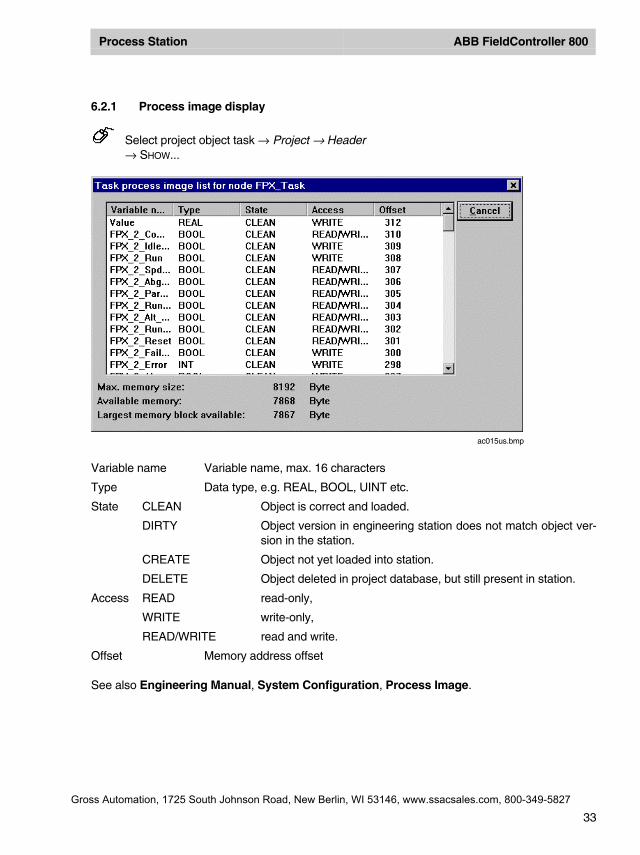
6.2.1 Process image display
Select project object task → Project → Header→ SHOW...
Variable name Variable name, max. 16 characters
Type Data type, e.g. REAL, BOOL, UINT etc.
State CLEAN Object is correct and loaded.
DIRTY Object version in engineering station does not match object ver-sion in the station.
CREATE Object not yet loaded into station.
DELETE Object deleted in project database, but still present in station.
Access READ read-only,
WRITE write-only,
READ/WRITE read and write.
Offset Memory address offset
See also Engineering Manual, System Configuration, Process Image.
ac015us.bmp
Gross Automation, 1725 South Johnson Road, New Berlin, WI 53146, www.ssacsales.com, 800-349-5827
Process Station ABB FieldController 800
34
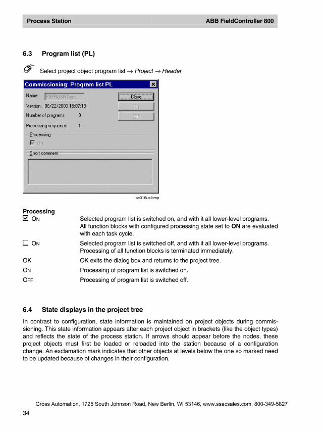
6.3 Program list (PL)
Select project object program list → Project → Header
ProcessingON Selected program list is switched on, and with it all lower-level programs.
All function blocks with configured processing state set to ON are evaluatedwith each task cycle.
ON Selected program list is switched off, and with it all lower-level programs.Processing of all function blocks is terminated immediately.
OK OK exits the dialog box and returns to the project tree.
ON Processing of program list is switched on.
OFF Processing of program list is switched off.
6.4 State displays in the project tree
In contrast to configuration, state information is maintained on project objects during commis-sioning. This state information appears after each project object in brackets (like the object types)and reflects the state of the process station. If arrows should appear before the nodes, theseproject objects must first be loaded or reloaded into the station because of a configurationchange. An exclamation mark indicates that other objects at levels below the one so marked needto be updated because of changes in their configuration.
ac016us.bmp
Gross Automation, 1725 South Johnson Road, New Berlin, WI 53146, www.ssacsales.com, 800-349-5827
Process Station ABB FieldController 800
35
The color of the node in the display provides information about the effects of its configurationchange on other objects. Higher-level information may also need to be updated in the station.
In commissioning, nodes are displayed in the same formats as in configuration.
See Engineering Manual, System Configuration, Project Tree, Display of project objectstates. The following details may appear after the object name and type. All states except Run-ning are displayed in red.
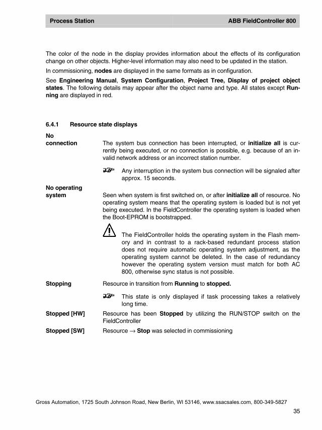
6.4.1 Resource state displays
Noconnection The system bus connection has been interrupted, or initialize all is cur-
rently being executed, or no connection is possible, e.g. because of an in-valid network address or an incorrect station number.
Any interruption in the system bus connection will be signaled afterapprox. 15 seconds.
No operatingsystem Seen when system is first switched on, or after initialize all of resource. No
operating system means that the operating system is loaded but is not yetbeing executed. In the FieldController the operating system is loaded whenthe Boot-EPROM is bootstrapped.
The FieldController holds the operating system in the Flash mem-ory and in contrast to a rack-based redundant process stationdoes not require automatic operating system adjustment, as theoperating system cannot be deleted. In the case of redundancyhowever the operating system version must match for both AC800, otherwise sync status is not possible.
Stopping Resource in transition from Running to stopped.
This state is only displayed if task processing takes a relativelylong time.
Stopped [HW] Resource has been Stopped by utilizing the RUN/STOP switch on theFieldController
Stopped [SW] Resource → Stop was selected in commissioning
Gross Automation, 1725 South Johnson Road, New Berlin, WI 53146, www.ssacsales.com, 800-349-5827
Process Station ABB FieldController 800
36
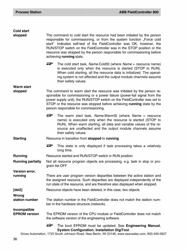
Cold startstopped The command to cold start the resource had been initiated by the person
responsible for commissioning, or from the system function „Force coldstart”. Indicates self-test of the FieldController was OK, however, theRUN/STOP switch on the FieldController was in the STOP position or theresource was stopped by the person responsible for commissioning beforeachieving running state.
The cold start task, Name.ColdSt (where Name = resource name)is executed only when the resource is started (STOP to RUN).When cold starting, all the resource data is initialized. The operat-ing system is not affected and the output module channels assumetheir safety values.
Warm startstopped The command to warm start the resource was initiated by the person re-
sponsible for commissioning or a power failure (power-fail signal from thepower supply unit), the RUN/STOP switch on the FieldController was set toSTOP or the resource was stopped before achieving running state by theperson responsible for commissioning.
The warm start task, Name.WarmSt (where Name = resourcename) is executed only when the resource is started (STOP toRUN). When warm starting, all data and variable values of the re-source are unaffected and the output module channels assumetheir safety values.
Starting Resource in transition from stopped to running
This state is only displayed if task processing takes a relativelylong time.
Running Resource started and RUN/STOP switch in RUN position
Running partially Not all resource program objects are processing, e.g. task in stop or pro-gram list OFF
Version error,running There are user program version disparities between the active station and
the assigned resource. Such disparities are displayed independently of therun state of the resource, and are therefore also displayed when stopped.
[del2] Resource objects have been deleted, in this case, two objects
Wrongstation number The station number in the FieldController does not match the station num-
ber in the hardware structure (network).
IncompatibleEPROM version The EPROM version of the CPU module or FieldController does not match
the software version of the engineering software.
The boot EPROM must be updated. See Engineering Manual,System Configuration, Installation DigiTool.
Gross Automation, 1725 South Johnson Road, New Berlin, WI 53146, www.ssacsales.com, 800-349-5827
Process Station ABB FieldController 800
37
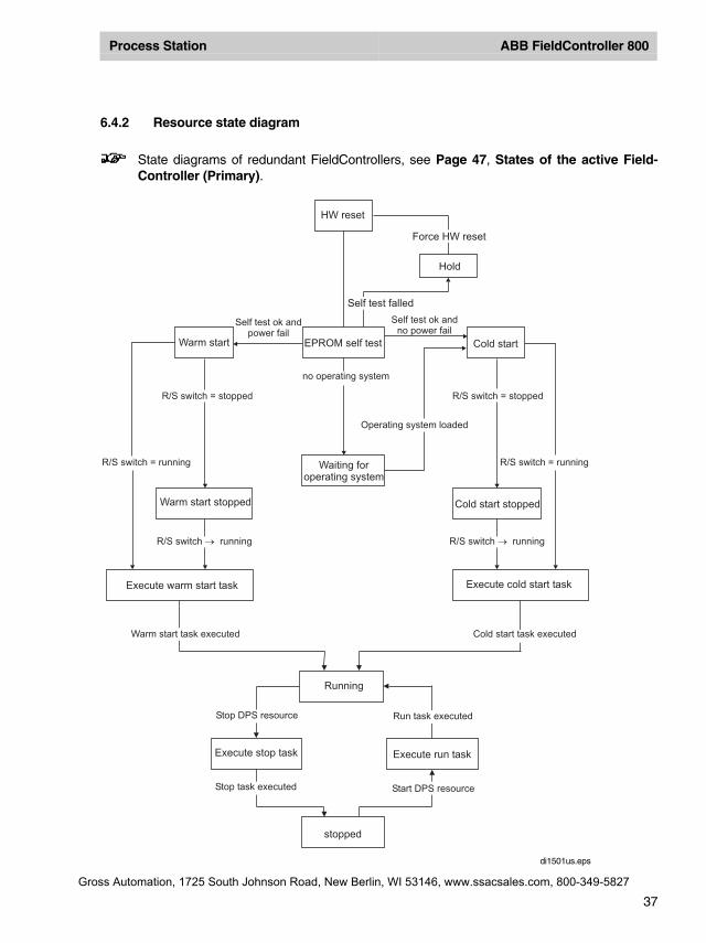
6.4.2 Resource state diagram
State diagrams of redundant FieldControllers, see Page 47, States of the active Field-Controller (Primary).
HW reset
Force HW reset
Hold
Self test falled
EPROM self test Cold start
Self test ok andpower fail
Self test ok andno power fail
Warm start
no operating system
Operating system loaded
R/S switch running�
R/S switch = runningR/S switch = running Waiting foroperating system
Warm start stopped Cold start stopped
R/S switch = stoppedR/S switch = stopped
R/S switch running�
Execute cold start taskExecute warm start task
Warm start task executed Cold start task executed
Run task executed
Start DPS resourceStop task executed
Running
Execute run taskExecute stop task
stopped
Stop DPS resource
di1501us.eps
Gross Automation, 1725 South Johnson Road, New Berlin, WI 53146, www.ssacsales.com, 800-349-5827
Process Station ABB FieldController 800
38
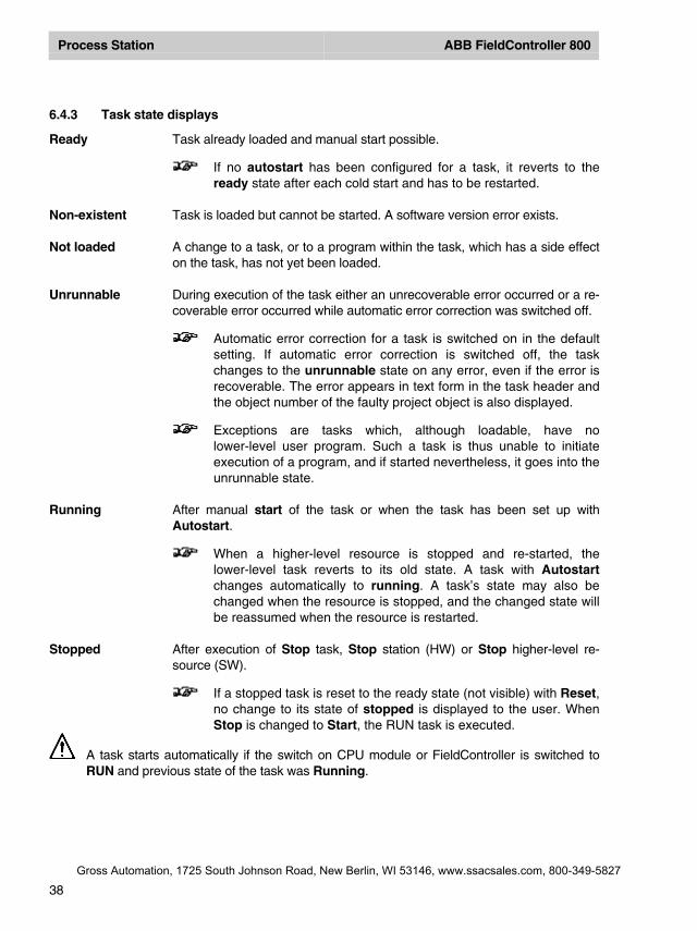
6.4.3 Task state displays
Ready Task already loaded and manual start possible.
If no autostart has been configured for a task, it reverts to theready state after each cold start and has to be restarted.
Non-existent Task is loaded but cannot be started. A software version error exists.
Not loaded A change to a task, or to a program within the task, which has a side effecton the task, has not yet been loaded.
Unrunnable During execution of the task either an unrecoverable error occurred or a re-coverable error occurred while automatic error correction was switched off.
Automatic error correction for a task is switched on in the defaultsetting. If automatic error correction is switched off, the taskchanges to the unrunnable state on any error, even if the error isrecoverable. The error appears in text form in the task header andthe object number of the faulty project object is also displayed.
Exceptions are tasks which, although loadable, have nolower-level user program. Such a task is thus unable to initiateexecution of a program, and if started nevertheless, it goes into theunrunnable state.
Running After manual start of the task or when the task has been set up withAutostart.
When a higher-level resource is stopped and re-started, thelower-level task reverts to its old state. A task with Autostartchanges automatically to running. A task’s state may also bechanged when the resource is stopped, and the changed state willbe reassumed when the resource is restarted.
Stopped After execution of Stop task, Stop station (HW) or Stop higher-level re-source (SW).
If a stopped task is reset to the ready state (not visible) with Reset,no change to its state of stopped is displayed to the user. WhenStop is changed to Start, the RUN task is executed.
A task starts automatically if the switch on CPU module or FieldController is switched toRUN and previous state of the task was Running.
Gross Automation, 1725 South Johnson Road, New Berlin, WI 53146, www.ssacsales.com, 800-349-5827
Process Station ABB FieldController 800
39
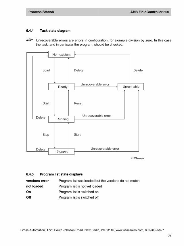
6.4.4 Task state diagram
Unrecoverable errors are errors in configuration, for example division by zero. In this casethe task, and in particular the program, should be checked.
6.4.5 Program list state displays
versions error Program list was loaded but the versions do not match
not loaded Program list is not yet loaded
On Program list is switched on
Off Program list is switched off
Non-existent
Ready
Stopped
Unrunnable
StartStop
Delete
Unrecoverable errorDelete
Load
ResetStart
Unrecoverable error
Delete
DeleteUnrecoverable error
Running
di1502us.eps
Gross Automation, 1725 South Johnson Road, New Berlin, WI 53146, www.ssacsales.com, 800-349-5827
Process Station ABB FieldController 800
40
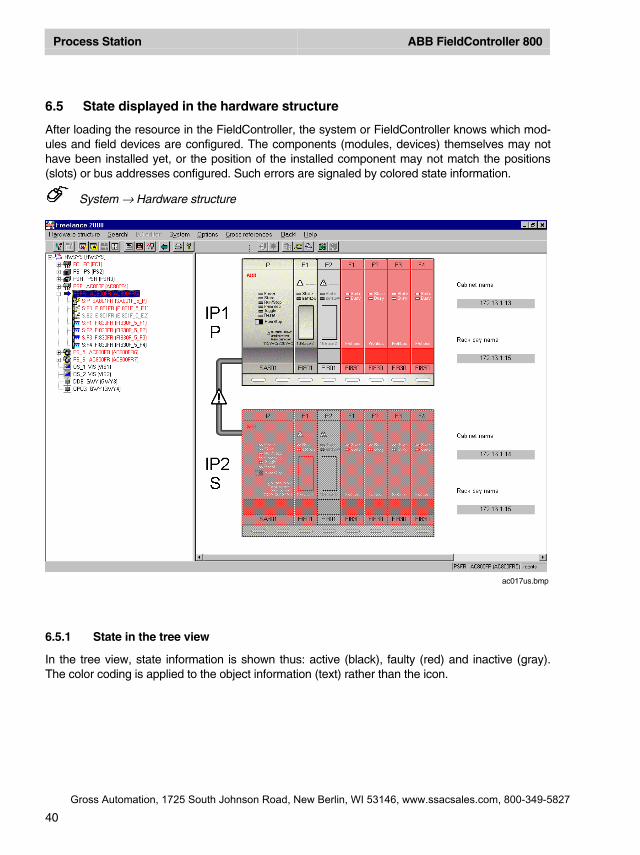
6.5 State displayed in the hardware structure
After loading the resource in the FieldController, the system or FieldController knows which mod-ules and field devices are configured. The components (modules, devices) themselves may nothave been installed yet, or the position of the installed component may not match the positions(slots) or bus addresses configured. Such errors are signaled by colored state information.
System → Hardware structure
6.5.1 State in the tree view
In the tree view, state information is shown thus: active (black), faulty (red) and inactive (gray).The color coding is applied to the object information (text) rather than the icon.
ac017us.bmp
Gross Automation, 1725 South Johnson Road, New Berlin, WI 53146, www.ssacsales.com, 800-349-5827
Process Station ABB FieldController 800
41
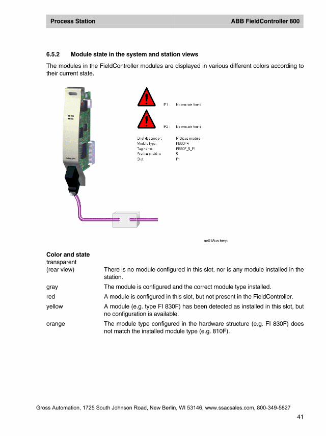
6.5.2 Module state in the system and station views
The modules in the FieldController modules are displayed in various different colors according totheir current state.
Color and statetransparent(rear view) There is no module configured in this slot, nor is any module installed in the
station.
gray The module is configured and the correct module type installed.
red A module is configured in this slot, but not present in the FieldController.
yellow A module (e.g. type FI 830F) has been detected as installed in this slot, butno configuration is available.
orange The module type configured in the hardware structure (e.g. FI 830F) doesnot match the installed module type (e.g. 810F).
ac018us.bmp
Gross Automation, 1725 South Johnson Road, New Berlin, WI 53146, www.ssacsales.com, 800-349-5827
Process Station ABB FieldController 800
42
6.5.3 State of the basic unit
On insertion into the hardware structure the FieldController is displayed with its basic unit. TheFieldController basic unit indicates whether the unit is active, inactive or faulty. Where a fault isindicated, this is generally due to the unit not being detected at all, i.e. not being installed or beingimpossible to address via the system bus.
dark gray The basic unit is activated.light gray The basic unit is not activatedred The basic unit cannot be addressed
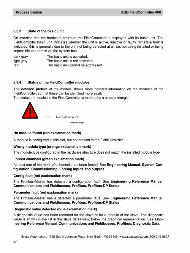
6.5.4 Status of the FieldController modules
The detailed picture of the module shows more detailed information on the modules of theFieldController, so that these can be identified more easily.The status of modules in the FieldController is marked by a colored triangle.
No module found (red exclamation mark)
A module is configured in this slot, but not present in the FieldController.
Wrong module type (orange exclamation mark)
The module type configured in the hardware structure does not match the installed module type
Forced channels (green exclamation mark)
At least one of the module's channels has been forced. See Engineering Manual, System Con-figuration, Commissioning, Forcing inputs and outputs.
Config fault (red exclamation mark)
The Profibus-Master has detected a configuration fault. See Engineering Reference Manual,Communications and Fieldbusses, Profibus, Profibus-DP States
Parameter fault (red exclamation mark)
The Profibus-Master has a detected a parameter fault. See Engineering Reference Manual,Communications and Fieldbusses, Profibus, Profibus-DP States
Diagnostic value detected (blue exclamation mark)
A diagnostic value has been recorded for the slave or for a module of the slave. The diagnosticvalue is shown in the list in the slave detail view, below the graphical representation. See Engi-neering Reference Manual, Communications and Fieldbusses, Profibus, Diagnostic Data.
ac019us.bmp
Gross Automation, 1725 South Johnson Road, New Berlin, WI 53146, www.ssacsales.com, 800-349-5827
Process Station ABB FieldController 800
43
7 Redundancy
In the case of redundancy a bumpless toggle is achieved between the active FieldController (Pri-mary)and a passive FieldController (Secondary), so that :
• in the case of CPU failure the outputs of the I/O components are maintained,• the internal states (component data, variable values) are maintained,• Configuration and working data are automatically adjusted between the active and passive
FieldController.
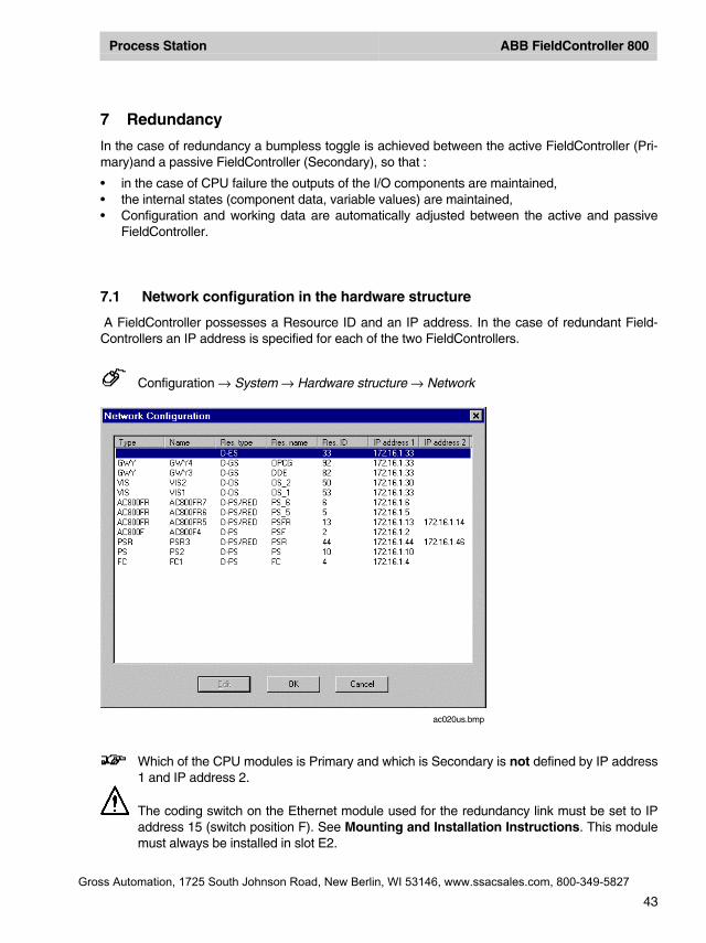
7.1 Network configuration in the hardware structure
A FieldController possesses a Resource ID and an IP address. In the case of redundant Field-Controllers an IP address is specified for each of the two FieldControllers.
Configuration → System → Hardware structure → Network
Which of the CPU modules is Primary and which is Secondary is not defined by IP address1 and IP address 2.
The coding switch on the Ethernet module used for the redundancy link must be set to IPaddress 15 (switch position F). See Mounting and Installation Instructions. This modulemust always be installed in slot E2.
ac020us.bmp
Gross Automation, 1725 South Johnson Road, New Berlin, WI 53146, www.ssacsales.com, 800-349-5827
Process Station ABB FieldController 800
44
7.2 Synchronization
The active FieldController (Primary) automatically ensures that the passive FieldController (Sec-ondary) can take over in the event of redundancy. The adjustment of operating system, user pro-grams and redundancy data necessary for this is performed via a redundancy connection, the re-dundancy link. The connection is produced at the front of FieldController and is implemented viaan Ethernet cable, optionally 10BASE2 (BNC), AUI, or twisted pair cable (TP) .
When the FieldController is bootstrapped one of the two FieldControllers automatically becomesthe Primary. The second FieldController recognizes a Primary on the station bus and reports tothe Primary as Secondary.
A newly plugged-in FieldController recognizes automatically that another FieldController isalready active on the station bus and moves automatically into the passive status.
In the adjustment between the active FieldController and a passive FieldController, a connectionis established via the redundancy link. The user program is transmitted from the Primary to theCPU.
The Secondary performs a cold start with these data and then logs on at the Primary. The currentprocess data are then transmitted to the Secondary. After successful transmission, both Field-Controllers move to “sync“ status. From now on, the Secondary is ready for a bumpless redun-dancy toggle. The relevant process data are adjusted cyclically.
The synchronization runs in parallel with the processing of the applications programs in the Field-Controller.
Depending on the Boot priority of the Secondary, side-effects can be avoided when synchronizingtasks. The higher the Boot priority of the Secondary compared to the processing priority of thetask (51 – 99), the faster the FieldController reaches Sync status.See also Engineering Manual, System Configuration, Project Tree, Process Station.
Gross Automation, 1725 South Johnson Road, New Berlin, WI 53146, www.ssacsales.com, 800-349-5827
Process Station ABB FieldController 800
45
7.3 Redundancy toggle
If any of the following occur at the Primary, a redundancy toggle is initiated deliberately betweenPrimary and Secondary:
• the Prim/Sec toggle switch of the FieldController is actuated,• the Prim/Sec button of the resource is actuated in commissioning mode,• the reset switch is actuated > 5 s, resulting in a cold start of the Primary,• the system function „Force redundancy toggle“ is executed.
7.4 Redundancy criteria
If the following have been established by the self-test diagnosis, a redundancy toggle betweenPrimary and Secondary is forced:
� a different module insertion has been detected in the two FieldControllers,� a module fault has occurred,� an equipment fault has been detected on the fieldbus module,• the watchdog has responded: a hardware fault has occurred on the FieldController,• a power fail of the power supply is reported,• a network fault (Ethernet) has occurred,• a “fatal software error” has occurred.
Gross Automation, 1725 South Johnson Road, New Berlin, WI 53146, www.ssacsales.com, 800-349-5827

Process Station ABB FieldController 800
46
7.5 Status diagram of the active FieldController (Primary)
sync
no OS
Secondary
no redundant
RedundancyError
not sync
no Secondary
Load user programms
Synchronizeprocess data
Redundancytoggle
StartResource
Redundancytoggle
Downloadoperating system
Redundancy dateoverflow
Load user programsin Secondary
Primary
Overload Resource
di1784us.sg
Gross Automation, 1725 South Johnson Road, New Berlin, WI 53146, www.ssacsales.com, 800-349-5827
Process Station ABB FieldController 800
47
7.6 States of the active FieldController (Primary)
The following redundancy states are displayed for the redundant resource reported on the re-source (project tree).
not redundant The operating system is loaded but the user program is not yet completelyloaded.
no Secondary Operating system and user programs are completely loaded. The Secon-dary has not yet logged on at the Primary.
not sync The Secondary FieldController is present, the operating system and theuser programs have been loaded but the process statuses have not yetbeen adjusted and the synchronization is therefore not yet concluded.
sync Normal status of the redundant FieldController. The Secondary is synchro-nized and ready for a redundancy toggle. The cyclic data adjustment be-tween the two FieldControllers runs during the program processing.
redundancy error Redundancy not possible..
The FieldController cannot achieve “sync” status. By restopping and then restarting the re-source, it was again attempted to reach “sync” status. The reason may be that it was notpossible to complete the loading of the user programs successfully.
The system loading is too high, the redundancy link cannot be maintained. The task cycletimes have been configured too short.
The volume of redundancy data to be transmitted for a task is too large. The system vari-able xxxx.RedBufLow indicates the remaining memory location for the redundancy datawith 0. The user programs have been distributed to too many tasks.
Gross Automation, 1725 South Johnson Road, New Berlin, WI 53146, www.ssacsales.com, 800-349-5827
Process Station ABB FieldController 800
48
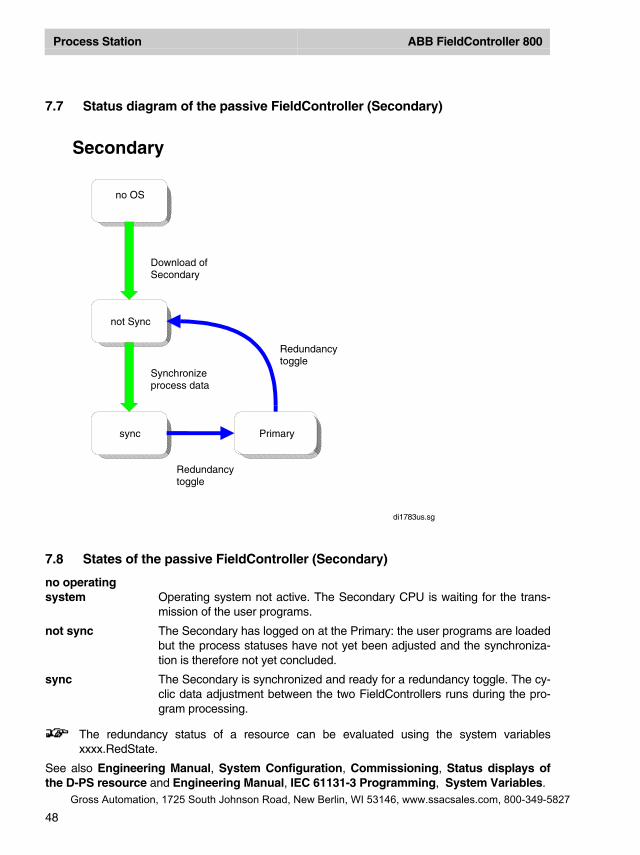
7.7 Status diagram of the passive FieldController (Secondary)
7.8 States of the passive FieldController (Secondary)
no operatingsystem Operating system not active. The Secondary CPU is waiting for the trans-
mission of the user programs.
not sync The Secondary has logged on at the Primary: the user programs are loadedbut the process statuses have not yet been adjusted and the synchroniza-tion is therefore not yet concluded.
sync The Secondary is synchronized and ready for a redundancy toggle. The cy-clic data adjustment between the two FieldControllers runs during the pro-gram processing.
The redundancy status of a resource can be evaluated using the system variablesxxxx.RedState.
See also Engineering Manual, System Configuration, Commissioning, Status displays ofthe D-PS resource and Engineering Manual, IEC 61131-3 Programming, System Variables.
Primarysync
not Sync
no OS
Redundancytoggle
Redundancytoggle
Download ofSecondary
Synchronizeprocess data
Secondary
di1783us.sg
Gross Automation, 1725 South Johnson Road, New Berlin, WI 53146, www.ssacsales.com, 800-349-5827
Process Station ABB FieldController 800
49
7.9 Technical data on Redundancy
Link monitoring Link monitoring between the Primary and a Secondary is carried out forFieldControllers linked via the CAN modules at 250 ms / 500 KBits/s (1250ms / 100 KBit/s). If the FieldControllers are only connected via the Red-Link(Ethernet), link monitoring is ??? (approx. half the speed).
Failure detection Both FieldControllers (Primary and Secondary) are processing a monitor-ing. The Secondary detects a failure of the Primary (redundancy toggle)within 20 ms / 500 KBit/s (40 ms / 100 KBit/s). The Primary detects a failureof the Secondary within 250 ms / 500 KBit/s (1250 ms / 100 KBit/s).If the redundancy link is used for failure detection the Secondary detects afailure of the Primary (redundancy toggle) within 40 ms / 500 KBit/s (80 ms /100 KBit/s). The Primary detects a failure of the Secondary within 500 ms /500 KBit/s (2500 ms / 100 KBit/s)
Redundancy toggle An automatic redundancy toggle is performed in less than 5 seconds if theactive FieldController (Primary) fails.
7.10 Changing a Non-Redundant Process Station into a Redundant one
• Export of every process station which should be redundant
a) block export of the resource process station in the project tree andb) block export of all hardware objects of the process station in the hardware structure.
Block import of sub-projects enables a resource to be automatically made redundant viathe menu item → Edit → Import block as redundant. This means that the project elementsare filed and all variables are written in process image mode. Export of the individual proc-ess stations enables the module insertion and I/O channel assignments to be accepted onre-import, instead of disappearing as would otherwise be the case.
• The variables of the task to be implemented redundantly must be written in process imagemode, otherwise they will not be redundancy-capable. Please check your user programs forvariables which are not written in the process image (column P in the variables list). If youconsider that these variables cannot be written in process image mode because the informa-tion within the task must be immediately available and may only be updated at the end of atask cycle, you should directly renew the resource allocation for the variables or relocate theprogram lists and Sequential Function Chart individually (see also next item)..
• The resources which are now to operate as redundant resources are deleted. Otherwise theredundant resources are automatically renamed on import into the project pool, since the ob-jects with the same name are still located in the project tree or the redundant tasks are in-serted under newly inserted redundant resources and the program lists and sequence pro-grams individually relocated. Please do not forget the contents of the system tasks. Thismethod should be chosen if all the variables cannot be written in process image mode or if notall the tasks have to operate redundantly.
• In the project tree and using Edit → Import block as redundant, insert the resources whichwere previously exported as redundant resources into the project pool.
Gross Automation, 1725 South Johnson Road, New Berlin, WI 53146, www.ssacsales.com, 800-349-5827
Process Station ABB FieldController 800
50
• Renew the resources assignment for the variables. This can be done manually or automati-cally.
• The global system variables for the previously non-redundant resources, which have beenused in programs or pictures, still have the previous resource allocation in the Variables List.The resource allocations must be changed to a possible new resource name.
These now undefined Identifiers are reported as errors in the plausibility check.
• In the hardware structure the individually exported blocks of the process stations must now beimported into a redundant process station so that all the information on insertion and I/O com-ponents becomes available once more.
When a rack-based process station PS is changed into a redundant FieldController AC800FR, the I/O modules must be imported individually as a block underneath the CAN-Master DNETP.
• Allocate the redundant resource to the redundant process station
• Plausibility check the project
Gross Automation, 1725 South Johnson Road, New Berlin, WI 53146, www.ssacsales.com, 800-349-5827
Process Station ABB FieldController 800
51
Index
A
Adding components ........................................................................................................................ 17
B
Battery module AM 801F ................................................................................................................ 27Boot parameter................................................................................................................................ 25
C
CAN ................................................................................................................................................... 8module FI 810F ........................................................................................................................... 28
CommissioningHardware structure ...................................................................................................................... 40
Configuration fault ........................................................................................................................... 42
D
Default namesModules ....................................................................................................................................... 20
Diagnosis information for modules.................................................................................................. 28Diagnostic data................................................................................................................................ 42
AC 800F....................................................................................................................................... 21DigiTool ............................................................................................................................................. 7DigiVis................................................................................................................................................ 7
E
Engineering station............................................................................................................................ 7EPROM-Download............................................................................................................................ 9Error code.................................................................................................................................. 28, 29
STA.............................................................................................................................................. 29Error handling of task ...................................................................................................................... 13Ethernet module .......................................................................................................................... 8, 27
EI 801F, EI 802F, EI 803F........................................................................................................... 27
F
Fieldbus module ................................................................................................................................ 8FieldController ................................................................................................................................... 7
AC 800F......................................................................................................................................... 7Forced ............................................................................................................................................. 42
H
Hardware structure.......................................................................................................................... 17
Gross Automation, 1725 South Johnson Road, New Berlin, WI 53146, www.ssacsales.com, 800-349-5827
Process Station ABB FieldController 800
52
I
I/O unit................................................................................................................................................8Insert
Modules........................................................................................................................................19
L
LoadOperating system and EPROM's...................................................................................................9Profibus module EPROM.............................................................................................................10
M
Modbus ..........................................................................................................................................7, 8Module
Detail view....................................................................................................................................42
N
Network configuration......................................................................................................................43
O
Operating systemD-PS/FC Resource ......................................................................................................................10Load .............................................................................................................................................10
P
Parameter fault ................................................................................................................................42Power fail .........................................................................................................................................16
signal ............................................................................................................................................16Power supply .....................................................................................................................................8
SA 801F 115/230 V AC ...............................................................................................................26SD 802F 24 V DC ........................................................................................................................26
Prim/Sec-Button...............................................................................................................................30Primary.............................................................................................................................................44Process image .................................................................................................................................33Process station bus ...........................................................................................................................7Profibus DP........................................................................................................................................8Profibus module FI 830F .................................................................................................................27Program list......................................................................................................................................34
Gross Automation, 1725 South Johnson Road, New Berlin, WI 53146, www.ssacsales.com, 800-349-5827
Process Station ABB FieldController 800
53
R
RedundancyCriteria ......................................................................................................................................... 45Data ............................................................................................................................................. 44Link .............................................................................................................................................. 44States........................................................................................................................................... 47States........................................................................................................................................... 46Toggle.......................................................................................................................................... 43Toggle.......................................................................................................................................... 45
Redundant ressourceStatus display .............................................................................................................................. 47
S
Secondary ....................................................................................................................................... 44Serial interface module FI 820F...................................................................................................... 27Service data
AC 800F....................................................................................................................................... 21Shutdown......................................................................................................................................... 16State display .............................................................................................................................. 40, 42
Diagnostic data detected............................................................................................................. 42Program list.................................................................................................................................. 39Resource ..................................................................................................................................... 35Task ............................................................................................................................................. 38
Station view ..................................................................................................................................... 19Symbols............................................................................................................................................. 5Synchronization............................................................................................................................... 44System bus........................................................................................................................................ 7
T
Task................................................................................................................................................. 32cold start ...................................................................................................................................... 31Error ............................................................................................................................................. 13Error handling .............................................................................................................................. 13Error messages ........................................................................................................................... 14State displays .............................................................................................................................. 38warm start .................................................................................................................................... 31
Typesof scripts......................................................................................................................................... 5of symbols...................................................................................................................................... 5
Gross Automation, 1725 South Johnson Road, New Berlin, WI 53146, www.ssacsales.com, 800-349-5827

Gross Automation, 1725 South Johnson Road, New Berlin, WI 53146, www.ssacsales.com, 800-349-5827