process-to-process delivery: udp, tcp, and sctp
TRANSCRIPT

23.1
Process-to-Process Delivery:
UDP, TCP, and SCTP
Copyright © The McGraw-Hill Companies, Inc. Permission required for reproduction or display.
23.2
PROCESS-TO-PROCESS DELIVERY
The transport layer is responsible for process-to-
process delivery—the delivery of a packet, part of a
message, from one process to another. Two processes
communicate in a client/server relationship, as we will
see later.
Client/Server Paradigm
Multiplexing and Demultiplexing
Connectionless Versus Connection-Oriented Service
Reliable Versus Unreliable
Three Protocols
Topics discussed in this section:

23.3
The transport layer is responsible for
process-to-process delivery.
Note
23.4
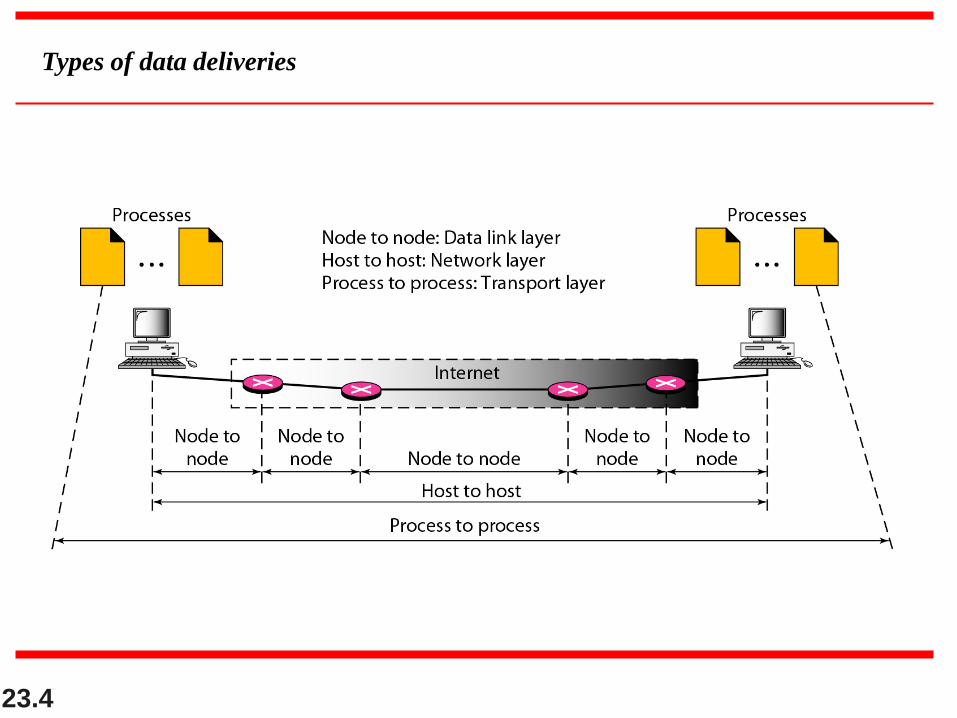
Types of data deliveries

23.5
Port numbers

23.6
IP addresses versus port numbers

23.7
Socket address

23.8
Multiplexing and demultiplexing

23.9
Reliable Vs Unreliable Error control
23.10
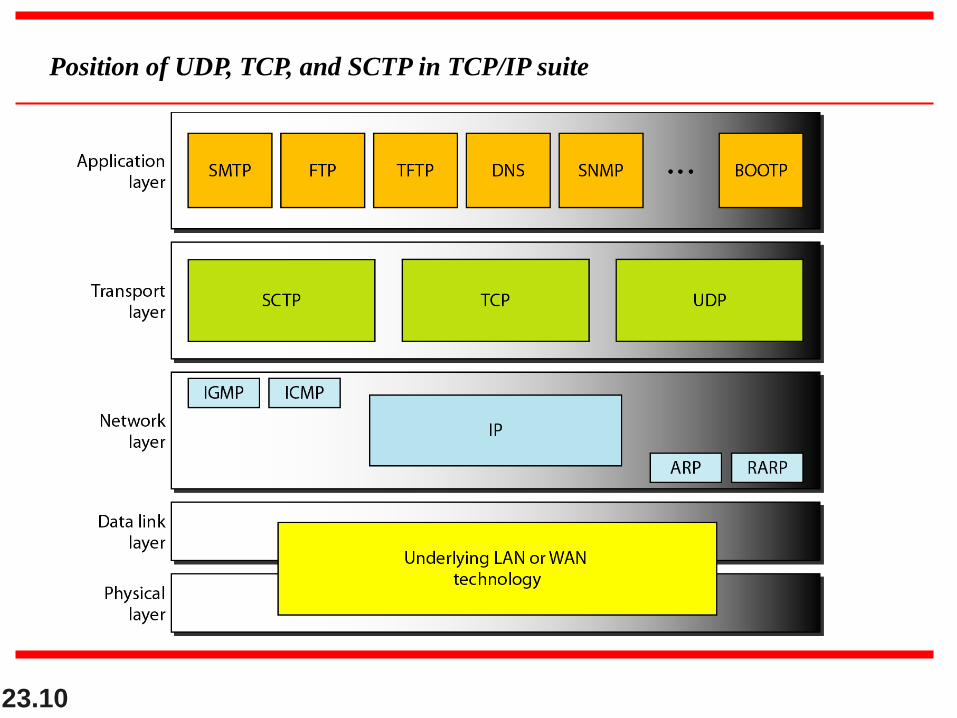
Position of UDP, TCP, and SCTP in TCP/IP suite

23.11
USER DATAGRAM PROTOCOL (UDP)
The User Datagram Protocol (UDP) is called a
connectionless, unreliable transport protocol. It does
not add anything to the services of IP except to provide
process-to-process communication instead of host-to-
host communication.
Well-Known Ports for UDP
User Datagram
Checksum
UDP Operation
Use of UDP
Topics discussed in this section:

23.12
User datagram format

23.13
UDP length
= IP length – IP header’s length
Note

Checksum calculation of a simple UDP user datagram
Transmission Control Protocol (TCP)
TCP is a connection-oriented protocol; it creates a
virtual connection between two TCPs to send data. In
addition, TCP uses flow and error control mechanisms
at the transport level.

TCP Services
1. Process to Process Communication
2. Stream Delivery Service
3. Sending and Receiving Buffers
4. Full Duplex Communication
5. Connection -Oriented Service
6. Reliable Service

Stream delivery

Sending and receiving buffers
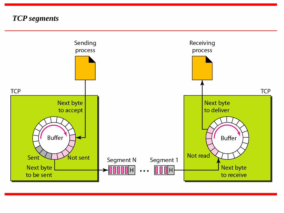
TCP segments

TCP Features
1. Numbering System
2. Flow Control
3. Error Control
4. Congestion Control
TCP Features
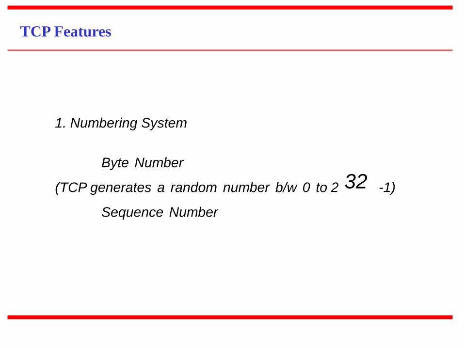
1. Numbering System
Byte Number
(TCP generates a random number b/w 0 to 2 32 -1)
Sequence Number
The bytes of data being transferred in
each connection are numbered by TCP.
The numbering starts with a randomly
generated number.
Note

Example
Suppose a TCP connection is transferring a file of 5000 bytes. The first byte is numbered 10,001.
What are the sequence numbers for each segment if data are sent in five segments, each carrying
1000 bytes?
The following shows the sequence number for each segment:
Example 23.3
23.24
The value in the sequence number field
of a segment defines the
number of the first data byte
contained in that segment.
Note

23.25
The value of the acknowledgment field
in a segment defines
the number of the next byte a party
expects to receive.
The acknowledgment number is
cumulative.
Note

TCP segment format
23.27
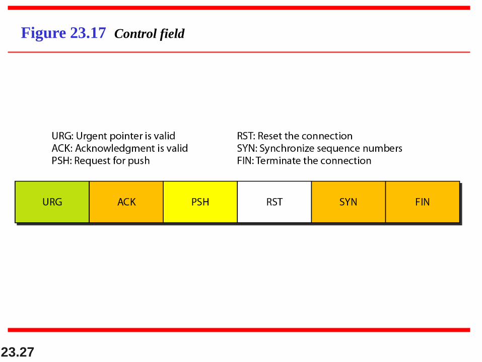
Figure 23.17 Control field
23.28
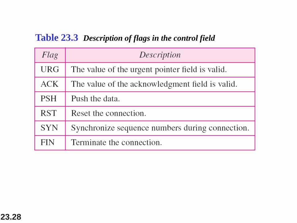
Table 23.3 Description of flags in the control field

23.29
Connection establishment using three-way handshaking

23.30
A SYN segment cannot carry data, but it
consumes one sequence number.
Note

23.31
A SYN + ACK segment cannot
carry data, but does consume one
sequence number.
Note
23.32
An ACK segment, if carrying no data,
consumes no sequence number.
Note

23.33
Figure 23.19 Data transfer

23.34
Figure 23.20 Connection termination using three-way handshaking
23.35
The FIN segment consumes one
sequence number if it does
not carry data.
Note
23.36
The FIN + ACK segment consumes
one sequence number if it
does not carry data.
Note

23.37
Question
Q:1 Explain TCP segment and UDP datagram format in detail.
Q:2 Explain TCP sending and receiving buffer with diagram.
23.38
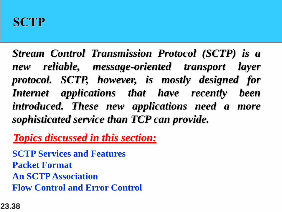
SCTP
Stream Control Transmission Protocol (SCTP) is a
new reliable, message-oriented transport layer
protocol. SCTP, however, is mostly designed for
Internet applications that have recently been
introduced. These new applications need a more
sophisticated service than TCP can provide.
SCTP Services and Features
Packet Format
An SCTP Association
Flow Control and Error Control
Topics discussed in this section:
23.39
SCTP is a message-oriented, reliable
protocol that combines the best features
of UDP and TCP.
Note

23.40
Process-to-Process Communication
Multiple Streams
Multihoming
Full-Duplex Communication
Connection-Oriented Service
Reliable Service
SCTP Services
23.41
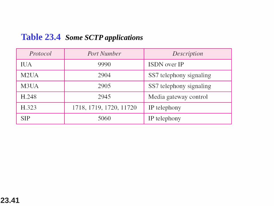
Table 23.4 Some SCTP applications
23.42
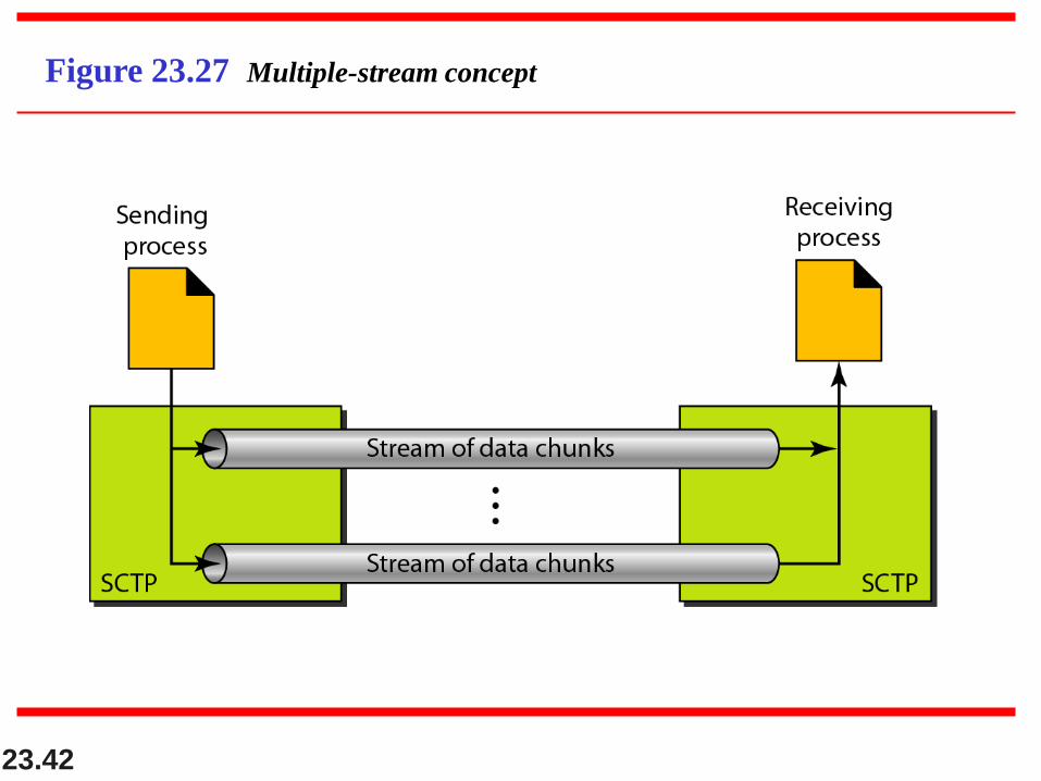
Figure 23.27 Multiple-stream concept

23.43
An association in SCTP can involve
multiple streams.
Note

23.44
Figure 23.28 Multihoming concept
23.45
SCTP association allows multiple IP
addresses for each end.
Note
23.46
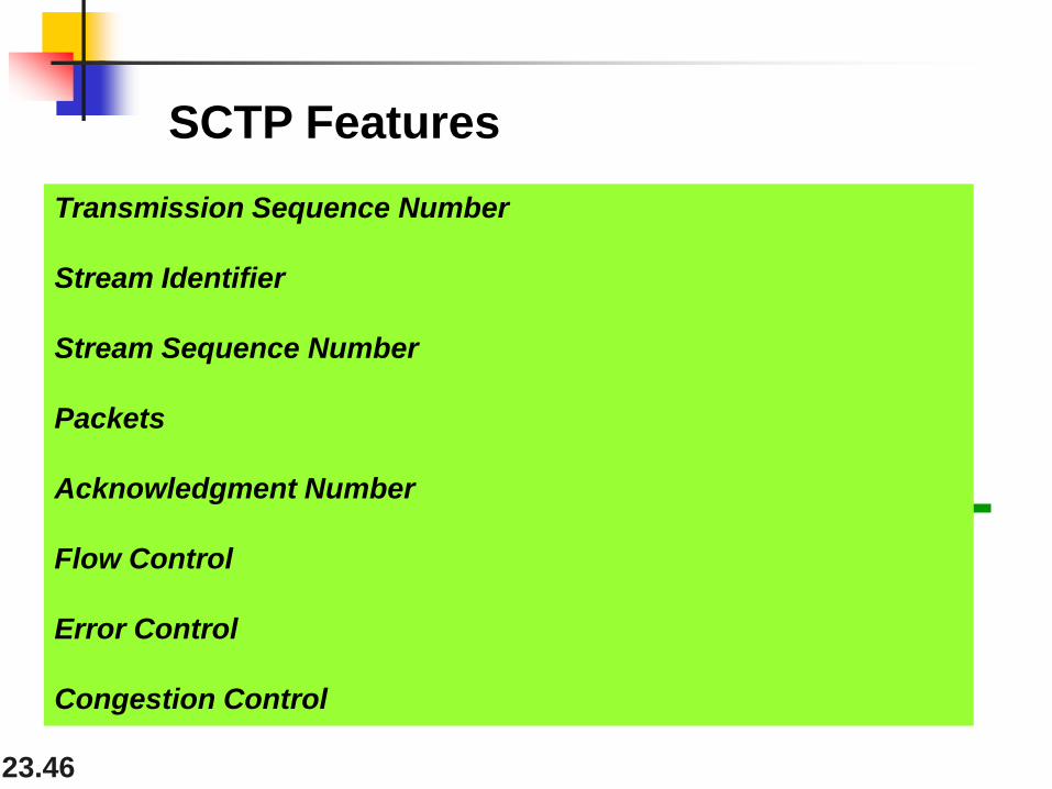
Transmission Sequence Number
Stream Identifier
Stream Sequence Number
Packets
Acknowledgment Number
Flow Control
Error Control
Congestion Control
SCTP Features

23.47
Transmission Sequence Number
SCTP Features
The unit of data in TCP is a byte. Data transfer in TCP is controlled by numbering bytes
by using a sequence number.
The unit of data in SCTP is a DATA chunk.
SCTP uses a transmission sequence number (TSN) to number the data chunks.
TSNs are 32 bits long and randomly initialized between 0 and 232 - 1.
23.48
In SCTP, a data chunk is numbered
using a TSN.
Note
TSN: Transmission Sequence Number
23.49
Stream Identifier
SCTP Features
In TCP, there is only one stream in each connection.
In SCTP, there may be several streams in each association.
Each stream in SCTP needs to be identified by using a stream identifier (SI).

23.50
To distinguish between different
streams, SCTP uses an SI.
Note

23.51
Stream Sequence Number
SCTP Features
When a data chunk arrives at the destination SCTP, it is delivered to the appropriate stream and
in the proper order.
SCTP defines each data chunk in each stream with a stream sequence number (SSN).

23.52
To distinguish between different data
chunks belonging to the same stream,
SCTP uses SSNs.
Note
SSN : Stream sequence number
23.53
Packets
SCTP Features
TCP has segments; SCTP has packets.

23.54
Figure 23.29 Comparison between a TCP segment and an SCTP packet

23.55
In SCTP, control information and data
information are carried in separate
chunks.
Note
23.56
let us suppose that process A needs to send 11 messages to process B in
three streams.
The first four messages are in the first stream, the second three
messages are in the second stream, and the last four messages are
in the third stream.
we assume that each message fits into one data chunk. Therefore, we
have 11 data chunks in three streams.
We also assume that the network allows only three data chunks per
packet, which
means that we need.
Example

23.57
Figure 23.30 Packet, data chunks, and streams

23.58
Data chunks are identified by three
items: TSN, SI, and SSN.
TSN is a cumulative number identifying
the association; SI defines the stream;
SSN defines the chunk in a stream.
Note
23.59
In SCTP, acknowledgment numbers are
used to acknowledge only data chunks;
control chunks are acknowledged by
other control chunks if necessary.
Note

23.60
Figure 23.31 SCTP packet format
23.61
In an SCTP packet, control chunks come
before data chunks.
Note

23.62
Figure 23.32 General header
23.63
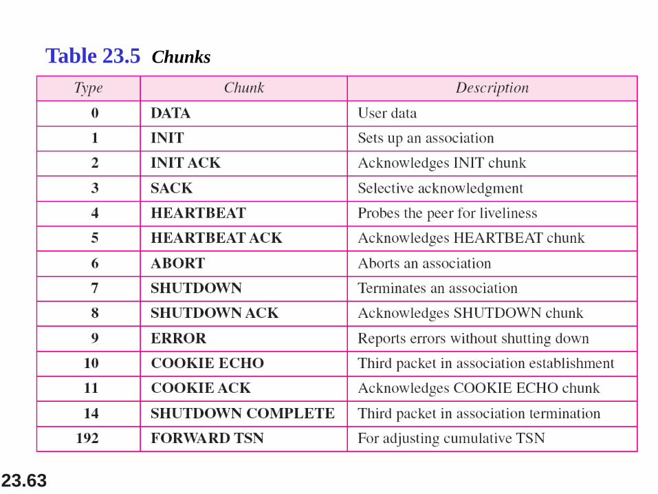
Table 23.5 Chunks

23.64
A connection in SCTP is called an
association.
Note
23.65
No other chunk is allowed in a packet
carrying an INIT or INIT ACK chunk.
A COOKIE ECHO or a COOKIE ACK
chunk can carry data chunks.
Note

23.66
Figure 23.33 Four-way handshaking

23.67
In SCTP, only DATA chunks
consume TSNs;
DATA chunks are the only chunks
that are acknowledged.
Note

23.68
Figure 23.34 Simple data transfer

23.69
The acknowledgment in SCTP defines
the cumulative TSN, the TSN of the last
data chunk received in order.
Note

23.70
Figure 23.35 Association termination
23.71
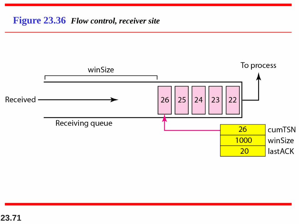
Figure 23.36 Flow control, receiver site
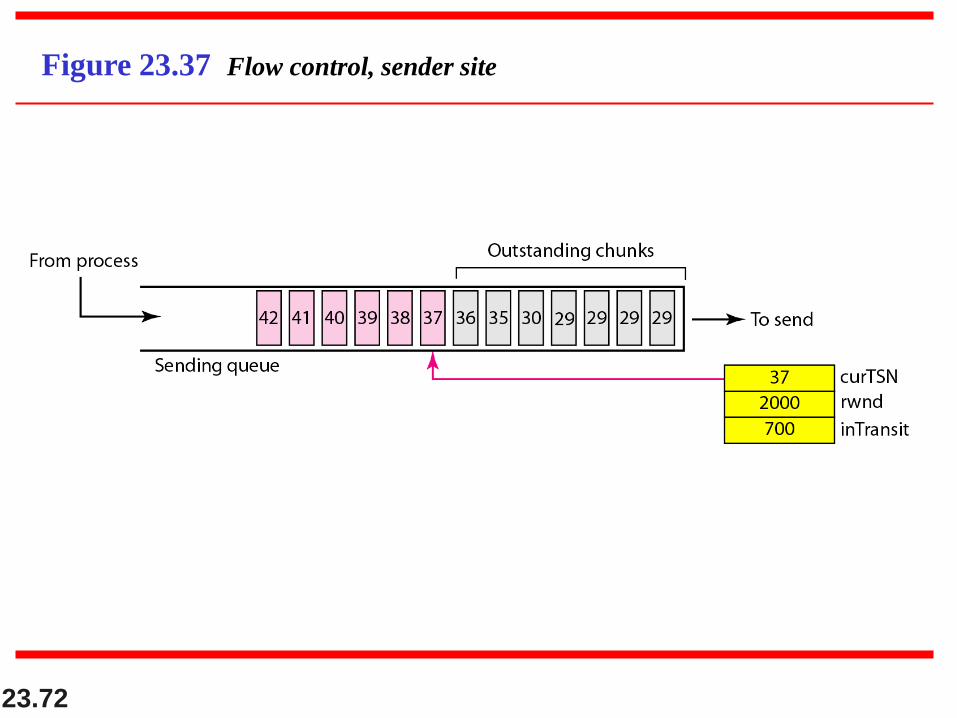
23.72
Figure 23.37 Flow control, sender site
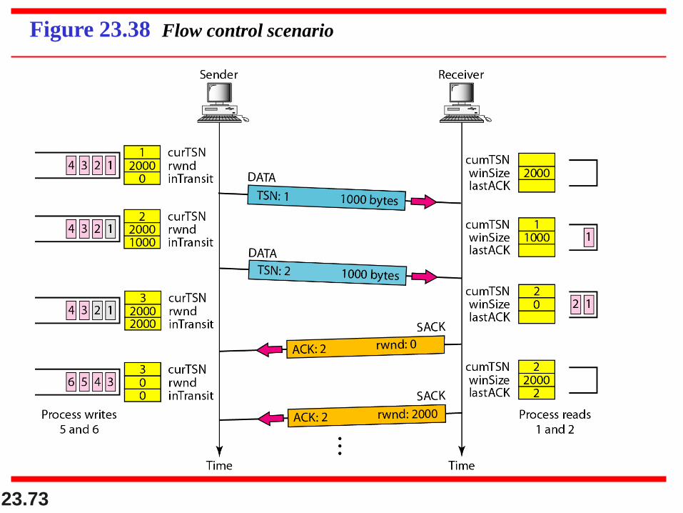
23.73
Figure 23.38 Flow control scenario

23.74
Figure 23.39 Error control, receiver site
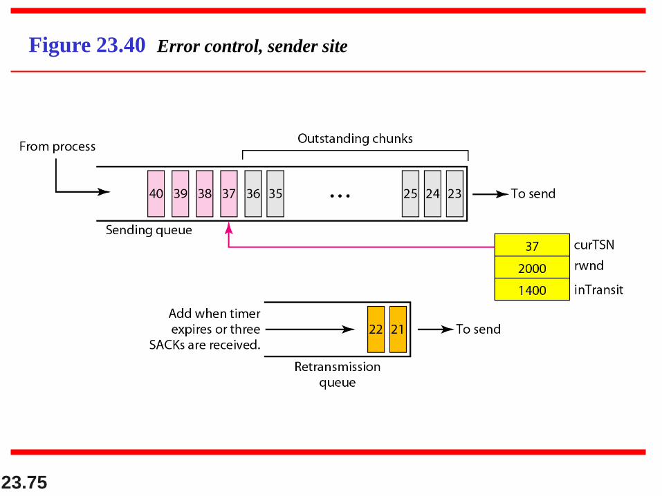
23.75
Figure 23.40 Error control, sender site

23.76
Figure 23.40 Error control, sender site