processing and characterization of glass flake …etd.lib.metu.edu.tr/upload/12617766/index.pdf ·...
TRANSCRIPT

PROCESSING AND CHARACTERIZATION OF GLASS FLAKE
REINFORCED THERMOPLASTIC POLYMER MATRIX BIO-INSPRIED
BULK LAMELLAR COMPOSITES
AYLİN GÜNEŞ
AUGUST 2014

PROCESSING AND CHARACTERIZATION OF GLASS FLAKE REINFORCED
THERMOPLASTIC POLYMER MATRIX BIO-INSPRIED BULK LAMELLAR
COMPOSITES
A THESIS SUBMITTED TO
THE GRADUATE SCHOOL OF NATURAL AND APPLIED SCIENCES
OF
MIDDLE EAST TECHNICAL UNIVERSITY
BY
AYLİN GÜNEŞ
IN PARTIAL FULFILLMENT OF THE REQUIREMENTS
FOR
THE DEGREE OF MASTER OF SCIENCE
IN
METALLURGICAL AND MATERIALS ENGINEERING
AUGUST 2014


Approval of the thesis:
PROCESSING AND CHARACTERIZATION OF GLASS FLAKE
REINFORCED THERMOPLASTIC POLYMER MATRIX BIO-INSPIRED
BULK LAMELLAR COMPOSITES
submitted by AYLİN GÜNEŞ in partial fulfillment of the requirements for the
degree of Master of Science in Metallurgical and Materials Engineering
Department, Middle East Technical University by,
Prof. Dr. Canan Özgen __________
Dean, Graduate School of Natural and Applied Sciences
Prof. Dr. C. Hakan Gür __________
Head of Department, Metallurgical and Materials Engineering
Assoc. Prof. Dr. Arcan Fehmi Dericioğlu _________
Supervisor, Metallurgical and Materials Engineering Dept. METU
Examining Committee Members:
Prof. Dr. Cevdet Kaynak _____________
Metallurgical and Materials Eng. Dept., METU
Assoc. Prof. Dr. Arcan Fehmi Dericioğlu ______________
Metallurgical and Materials Eng. Dept., METU
Prof. Dr. Cemil Hakan Gür ______________
Metallurgical and Materials Eng. Dept., METU
Assist. Prof. Dr. Mert Efe ______________
Metallurgical and Materials Eng. Dept., METU
Prof. Dr. Göknur Bayram ______________
Chemical Engineering Dept., METU
Date:21.08.2014

iv
I hereby declare that all information in this document has been obtained and
presented in accordance with academic rules and ethical conduct. I also declare
that, as required by these rules and conduct, I have fully cited and referenced all
material and results that are not original to this work.
Name, Last name : Aylin Güneş
Signature :

v
ABSTRACT
PROCESSING AND CHARACTERIZATION OF GLASS FLAKE
REINFORCED THERMOPLASTIC POLYMER MATRIX BIO-INSPRIED BULK
LAMELLAR COMPOSITES
Güneş,Aylin
MSc., Department of Metallurgical and Materials Engineering
Supervisor: Assoc. Prof. Dr. Arcan F. Dericioğlu
August 2014, 104 pages
The aim of this study was to develop processing pathways to fabricate glass flake
reinforced bio-inspired composites with microstructural architecture similar to that of
nacre using two processing routes based on hot-pressing and magnetic field
assistance. Glass flakes with different aspect ratios were used as inorganic
reinforcement in two different thermoplastic matrices, polystyrene (PS) and
acrylonitrile butadiene styrene (ABS). Correlation between inorganic content,
microstructural architecture and mechanical property enhancement of the composites
fabricated by various process combinations was examined. To investigate the effect
of inorganic-organic phase interfacial interaction and adhesion on the mechanical
properties of the fabricated composites, glass flakes surfaces were treated with an
organofunctional silane called aminopropyltriethoxy silane. X-Ray Photoelectron
Spectroscopy (XPS) was used to analyze the adsorption of silane molecules on the
inorganic reinforcement surfaces. Mechanical properties of the fabricated composites
were examined using three point bending, micro hardness and work of fracture tests.
Results indicated that hot-pressing and magnetic field assistance based methods are
easy and effective pathways to fabricate nacre-like bulk inorganic-organic
composites with brick and mortar microstructural architecture. Composites fabricated
by these two different pathways reinforced by glass flakes exhibited improved
mechanical characteristics such as higher flexural strength, stiffness and hardness.
Treatment of the glass flake surfaces by silane further enhanced the mechanical
properties of the fabricated composites, where it provided simultaneous improvement
in both strength and fracture resistance of the composites, which is the main
challenging task to be achieved in the field of materials science from a structural
point of view.
Keywords: Bio-inspired composites, Artificial nacre, Hot-pressing based methods,
Magnetic Field Assistance based methods, Silane coupling

vi
ÖZ
CAM PLAKA TAKVİYELİ TERMOPLASTİK POLİMER MATRİSLİ DOĞADAN
ESİNLENİLMİŞ HACİMLİ KOMPOZİT ÜRETİMİ VE KARAKTERİZASYONU
Güneş, Aylin
Yüksek Lisans,Metalurji ve Malzeme Mühendisliği Bölümü
Tez Yöneticisi: Doç.Dr. Arcan Fehmi Dericioğlu
Ağustos 2014, 104 sayfa
Bu çalışma kapsamında, sıcak presleme ve manyetik alanla destekleme tabanlı
yöntemler kullanılarak mikroyapısı itibariyle doğal sedefe benzeyen cam plaka
takviyeli kompozitlerin üretimi amaçlanmıştır. Polistren (PS) ve akrilonitril
butadiyen stren (ABS) olmak üzere iki farklı termoplastik matris malzemesi ve en-
boy oranı farklı cam plaka takviye malzemesi kullanılmıştır. Çeşitli yöntemlerle
üretilen kompozitlerde farklı miktardaki inorganik malzemenin mikroyapısı ve
mekanik özelliklere etkileri araştırılmıştır. İnorganik ve organik fazlar arasındaki
arayüzey etkileşimi ve tutunmanın üretilen kompozitlerin mekanik özelliklerine
etkilerini araştırmak amacıyla cam plaka yüzeyleri aminopropiltrietoksi silan olarak
adlandırılan bir organofonksiyonel silan ajanıyla modifiye edilmiştir. Modifiye
edilmiş inorganik takviye malzeme yüzeyleri X-Işınları Fotoelektron Spektroskopi
(XPS) yöntemi ile karakterize edilerek silan ajan malzemesinin yüzeye tutunup
tutunmadığı incelenmiştir. Üretilen kompozitlerin mekanik özellikleri üç noktadan
bükülme, mikro sertlik ve kırılma testleri kullanılarak belirlenmiştir.
Elde edilen sonuçlar, sıcak presleme ve manyetik alanla destekleme tabanlı
yöntemlerin sedef benzeri tuğla-ve-harç mikroyapı mimarisine sahip hacimli
inorganik-organik kompozit malzemelerin üretiminde kullanılabilecek kolay ve
efektif bir üretim metodu olduğunu göstermiştir. İki farklı tabana dayalı üretim
metotlarıyla üretilen ve cam plaka takviye malzemesiyle güçlendirilen kompozitler
eğme mukavemeti, eğilmezlik ve sertlik özelliklerinde gelişme göstermiştir.
Silanlama ile yüzeyleri modifiye edilen cam plakalarla takviye edilmiş kompozitler
yapısal malzeme alanındaki asıl amaç olan eş zamanlı olarak yüksek mukavemet ve
kırılma dayanımına sahip olma yönünde mekanik özelliklerinde gelişme göstermiştir.
Anahtar Kelimeler: Doğadan esinlenilen kompozitler, Yapay sedef, Sıcak presleme
destekleme tabanlı yöntemler, Manyetik alan destekleme tabanlı yöntemler,
Silanlama.

vii
To My Family

viii
ACKNOWLEDGEMENTS
Foremost, I would like to thank Assoc. Prof. Arcan Fehmi Dericioğlu for tremendous
guidance, incredible patience, support, extraordinary encouragement and trust.
Moreover, I would thank Prof. Dr. Şakir Bor for his indebted guidance, tremendous
help and support.
I am thankful to my previous and current lab mates: Eda Aydoğan, Özgür Hamat,
Güney Daloğlu, Dr. Selen Nimet Gürbüz Güner, Simge Tülbez and Seray Kaya and
to my friends: Murat Yalçın, Özgür Başkan Taştan and especially to Emin Erkan
Aşık, Dr. Gül İpek Nakaş and Bensu Tunca and I am grateful for precious love and
support to Boğaç Karçıka.
I am also grateful to all the staff of the Department of Metallurgical and Materials
Engineering, Res. Assoc. Serkan Yılmaz, Önder Şahin and Yusuf Yıldırım.
I owe a depth to my dear family for their endless love, support and encouragement
throughout my life.

ix
TABLE OF CONTENTS
ABSTRACT v
ÖZ vi
ACKNOWLEDGEMENTS viii
TABLE OF CONTENTS ix
LIST OF TABLES xii
LIST OF FIGURES xiii
CHAPTERS
1. INTRODUCTION .............................................................................................. 1
2. LITERATURE REVIEW .................................................................................. 5
2.1 Natural Materials .................................................................................................... 5
2.2 Composite Materials .............................................................................................. 6
2.3 Bio-inspired Materials ............................................................................................ 7
2.4 Nacre ...................................................................................................................... 9
2.4.1 Mechanical Behavior of Nacre ......................................................... 13
2.4.2 Hierarchical Structure of Nacre ........................................................ 16
2.4.3 Organic Phase in Mollusc Shell Structure ........................................ 21
2.4.4 Possible Fabrication Methods of Composite Materials Inspired by
Nacre .......................................................................................................... 26
2.5 Inorganic Surface Functionalization with Organofunctional Silane .................... 31
x
2.6 Applied Surface Characterization Techniques ..................................................... 32
2.6.1 X-Ray Photoelectron Spectroscopy .................................................. 32
2.6.2 Fourier Transformed Infrared Spectroscopy ..................................... 32
3. EXPERIMENTAL PROCEDURE ................................................................... 33
3.1 Raw Materials ....................................................................................................... 36
3.2. Fabrication of Nacre-Like Polystyrene or Acrylonitrile Butadiene Styrene
Matrices Bulk Lamellar Composites Using As Received Glass Flakes .................... .41
3.3 Fabrication of Nacre-Like Bulk Lamellar Thermoplastic Matrix Composites
Using Surface Modified Glass Flakes ....................................................................... 46
3.3.1 Surface Modification of Glass Flakes with Aminopropyltriethoxy
Silane ......................................................................................................... 46
3.3.2 Surface Modification Cationic Magnetite Nanoparticle Solution .... 47
3.3.3 Fabrication of Polystyrene Matrix Composites Reinforced by Surface
Modified Glass Flakes 48
3.4 Characterization .................................................................................................... 49
3.4.1 Determination of Inorganic Reinforcement Content and Density .... 49
3.4.2 Microstructural Characterization ...................................................... 50
3.4.3 Mechanical Characterization ............................................................ 50
3.4.3.1 Hardness Measurement ............................................................ 50
3.4.3.2 Three-Point Bending Tests ....................................................... 51
3.4.3.3 Work of Fracture Tests ............................................................. 51
xi
3.4.4 X-Ray Photoelectron Spectroscopy (XPS) ....................................... 52
3.4.5 Fourier Transform Infrared Spectroscopy (FTIR) ............................ 52
4. RESULTS AND DISCUSSION ...................................................................... 53
4.1 Fabrication of Nacre like Bulk Lamellar Thermoplastic Polymer Matrix
Composite Materials .................................................................................................. 53
4.2 Magnetite Nanoparticle Attached Gkass Flake Reinforced Nacre-Like Bulk
Lamellar Composites Fabricated by Magnetic Field Assistance . ............................. 80
5. CONCUSION ................................................................................................... 93
REFERENCES 97

xii
LIST OF TABLES
TABLES
Table 3.1. Properties of glass flakes used in this dissertation 36
Table 3.2. Chemical Analysis of glass flakes 37
Table 4.1. Inorganic content, density, relative density (%) and hardness obtained by
four different process combinations in ABS or PS matrix composites ...................... 59
Table 4.2. Inorganic content, density, relative density (%) and hardness of
AC+HASC processed ABS or PS matrix composites reinforced by as-received or
silane treated glass flakes .......................................................................................... 75
Table 4.3. Density, relative density (%) and hardness of the fabricated composites for
three different initial polymer contents (wt% PS 85

xiii
LIST OF FIGURES
FIGURES
Figure 2.1 (a) water strider, (b) sem images of a water strider leg covered by
numerous oriented needle-shaped microsetae, (c) sem image of grooved
nanostructure on the seta surface [39], (d) bio inspired au/tio2 photocatalyst derived
from butterfly wing (papilio paris) [40] 8
Figure 2.2 Overall view of hierarchical structure of abalone shell, showing
mesolayers, mineral tiles, tile pullout in a fracture region [41] 9
Figure 2.3 The hierarchical structure of nacre (Growth line image from Menig et al.
(2000), Nanograins from Rousseau et al. (2005)) [2] 10
Figure 2.4 Strength vs density of natural materials [4] 11
Figure 2.5 Comparison of mollusc shell with other natural materials in terms of
toughness –modulus diagram [4] 12
Figure 2.6 (a) Stress-strain curve of nacre in tension along the tablets, (b) schematic
showing tablet sliding [42] 14
Figure 2.7 (a) Stress – strain curves of simple shear (s-s) and shear compression (s-c)
responses of dried and hydrated nacre, (b) transverse strain as function of shear strain
[42] 15
Figure 2.8 Strength of nacre under different loading directions [44] 15

xiv
Figure 2.9 Hierarchical structure of nacre [50-54] 17
Figure 2.10 Interlocking mechanisms in nacre [19] 18
Figure 2.11 (a) Schematic illustration showing interlocks between platelets of nacre
showing that rotation of levels of platelets is essential for the formation of platelet
interlocks, (b) schematic illustration showing the mechanism of loading through a
cross-section cut across platelets and (c) through the interlocks [19] 19
Figure 2.12 Stress-strain plots of nacre with interlocks as obtained from 3D finite
element simulations with failure sequence of interlocks superimposed. The stress-
strain plot shows good strength as well as high toughness which is proportional the
area under the curve [19] 20
Figure 2.13 Various views of organic layer in nacre subjected to tensile test (Field-
emission SEM); (a, b) layers hanging between two tiles (marked with arrow); (c, d)
top view of tile surface with organic layer networks [41] 22
Figure 2.14 Increase of modulus of elasticity of nacre as a function of the Poisson’s
ratio of the organic matrix [18] 23
Figure 2.15 (a) Stress-strain curves measured in tensile test of dried and hydrated
nacre. The insets illustrate the deformation behavior during loading, (b) deformation
behavior in the work-hardening stage in the stress-strain curve( SEM image).
Platelets are progressively pulled out in an accumulative manner [8] 24
Figure 2.16 Schematic diagram of deformation behavior of proteins with modular
structures [8]. 25

xv
Figure 2.17 Hierarchical toughening mechanism of nacre. Toughening can be
classified according to the operating dimension, from an inter-platelet mechanism
operating at the sub micrometer scale, to an intra-platelet mechanism of the order of
several tens of nanometers, down to individual organic molecules (nm scale) [8] 25
Figure 2.18 Schematic illustration for the fabrication of artificial nacre (a) LBL, self-
assembly of DAR/PAA multilayered film via the alternating deposition method; (b)
preparation of CaCO3 nanolaminated structure on the DAR/PAA multilayered films
by CO2 gas diffusion method; (c) preparation of the multilayer organic/inorganic
hybrid composite by alternately repeating steps (a) and (b) [60] 27
Figure 2.19 Bottom up colloidal assembly of multilayered hybrid films. Surface
modified platelets are assembled at the air-water interface to produce a highly
oriented layer of platelets after ultrasonication. The 2D assembled platelets are
transferred to a flat substrate and afterwards covered with a polymer layer by
conventional spin coating [61] 28
Figure 2.20 Schematic İllustration of Hot press Assisted Slip Casting (HASC)
Method [13] 29
Figure 2.21 Processing route for the production of platelet-reinforced composites
with tailored architectures using mechanical and magnetic stimuli. Solenoids are used
to keep the alignment of the ultrahigh magnetic response (UHMR) -platelets while
curing the composites inside an oven at 60°C [15] 30
Figure 2.22 Silane treatment reactions [65] 31

xvi
Figure 3.1 Flow chart of the fabrication procedures applied in this study (a) Hot-
Pressing based methods, (b) Magnetic Field Assistance based method 34
Figure 3.2 Scanning electron microscope images a) Micronised glass flakes, b)
Unmilled glass flakes 37
Figure 3.3 Polystyrene a) structure of monomer and polymer b) structure of
syndiotactic Polystyrene (PS) in highly crystalline form 39
Figure 3.4 Different chemical structures in ABS 40
Figure 3.5 Chemical structure of Acrylonitrile Butadiene Styrene 40
Figure 3.6 Chemical Structure of Aminopropyltriethoxy silane 41
Figure 3.7 Schematic representation of Tape Casting (TC) method 45
Figure 3.8 Schematic representation of Hot press Assisted Slip Casting (HASC)
method 45
Figure 3.9 Silane treatment reactions 47
Figure 4.1. Fracture surfaces of TC+HASC processed PS matrix composites
composed of different glass flake mixtures containing (a) 10 wt%, (b) 20 wt%, (c) 5
wt%, (d) 80 wt% and (e) 90 wt% high aspect ratio glass flakes (GF 750) 55
Figure 4.2. Scanning electron microscope images of the a) ABS matrix and b) PS
matrix composites fabricated by AC+HP process where the pores are shown by
arrows 60

xvii
Figure 4.3. Scanning electron microscope images of composites fabricated by
TC+HASC route (a) presence of spherical pores, (b) adhesion of the polymer matrix
on the glass flake surfaces. 61
Figure 4.4. Schematic representation of the simple mixed and tape casted films into
steel die before hot press assisted slip casting solution 63
Figure 4.5. Flowing of polymer solution like plug between flakes [21] 64
Figure 4.6. Restitution in a viscoelastic fluid [21] 65
Figure 4.7. Scanning electron microscope images of the fracture surfaces of the three
point bending tested PS matrix composites fabricated by (a) AC+HASC, (b)
TC+HASC, (c) TC+HP and (d) AC+HP 66
Figure 4.8. Scanning electron microscope images of the fracture surfaces of the three
point bending tested ABS matrix composites fabricated by (a) AC+HASC, (b)
TC+HASC, (c) TC+HP and (d) AC+HP 67
Figure 4.9. Flexural stress vs. strain curves of PS matrix composites fabricated by
the four process combinations 69
Figure 4.10. Flexural stress vs. strain curves of ABS matrix composites fabricated by
the four process combinations 69
Figure 4.11. Variation in mechanical properties of acrylonitrile butadiene styrene and
polystyrene polymer matrices composites fabricated by AC+HASC method. 71
Figure 4.12. XPS spectra of (a) as-received and (b) silane treated glass flakes 73

xviii
Figure 4.13. Fracture surfaces of three point bending tested AC+HASC processed
PS matrix composites reinforced by (a) and (c) as-received and (b) and (d) silane
treated glass flakes 76
Figure 4.14. Fracture surfaces of three point bending tested AC+HASC processed
ABS matrix composites reinforced by (a) and (c) as-received and (b) and (d) silane
treated glass flakes. 77
Figure 4.15. Flexural stress vs. strain curves of AC+HASC processed PS and ABS
matrix composites reinforced by as-received and silane treated glass flakes 78
Figure 4.16. Schematic representation of the interaction between
aminoproyltriethoxy silane and polymer chains [23] 79
Figure 4.17. Load- extension curves of SENB specimens of AC+HASC processed
PS and ABS matrix composites reinforced by as-received and silane treated glass
flakes 80
Figure 4.18. Color difference between as-received and nanoparticle attached glass
flakes before and after filtering the processing solution 81
Figure 4.19 Optical microscope image of the surface modified glass flakes aligned on
the hard magnet 82
Figure 4.20 FTIR spectra of (a) as-received and (b) magnetite nanoparticle attached
glass flakes 83

xix
Figure 4.21 Fracture surfaces of the three point bending tested composites fabricated
by magnetic field assistance and HP containing (a) 38 wt %, (b) 43 wt % and (c) 53
wt % PS matrix 86
Figure 4.22. Three point bending test data of composites fabricated by magnetic
field assistance followed by HP having different amounts of polymer matrix 87
Figure 4.23. Schematic representation of the chemical interaction between the
magnetite nanoparticles attached on the glass flake surfaces with polystyrene
molecules 88
Figure 4.24. Fracture surfaces of the three point bending tested 53 wt% PS matrix
containing composites fabricated by magnetic field assistance and HP reinforced by
(a) only magnetite nanoparticle attached glass flakes and (b) magnetite nanoparticle
attached and then silane treated glass flakes 89
Figure 4.25. Three point bending test data of composites fabricated by magnetic
field assistance followed by HP having different amounts of polymer matrix also
including the silane treated one 90
Figure 4.26. Load vs. extension curves of WOF tested composites fabricated by
magnetic field assistance followed by HP process having different amounts of
polymer matrix also including the silane treated one 91

xx

1
CHAPTER 1
INTRODUCTION
In the last few years, needs of mankind has increased extremely, and hence,
people need to innovative new structural materials especially for energy,
defense and aerospace applications. Materials to be fabricated or redesigned
should not only supply basic requirements for a specific life time but also
should be energy efficient and environment friendly during their production
and service. As a result of these, scientists have been focusing on the natural
materials, which have excellent microstructural architectures and designs
leading to extraordinary mechanical property combinations, creating a new
scientific area called “Bio- inspired” materials [1-5].
Nature has extraordinary composite materials that have unique designs and
properties. Among most of the natural composites, nacre demonstrates high
strength along with high fracture resistance based on its unique architectural
design. Nacre, the mother-of-pearl, located on the interior surface of the
mollusc shell is a natural composite composed of an inorganic and organic
component (95 vol% CaCO3 and 5 vol% protein) [6-10] efficiently
combining these components providing unique mechanical properties.
Although there are successful results reporting on the brick and mortar
architecture composed of thermoset polymers as the organic component and
CaCO3, alumina or glass platelets as inorganic component [11,12-21],
mechanical test results illustrated low fracture resistance due to the inherent
brittleness of the thermoset polymers used in the structure. Therefore, to
overcome this limitation changing the polymer type to thermoplastics could

2
be a solution to reach improvement in the mechanical behavior. In this
research, use of thermoplastic polymers namely polystyrene and
acrylonitrile butadiene styrene and glass flakes with different dimensions in
nacre-like bio-inspired composites has been proposed.
In the last years, there are numerous studies about bio-inspired materials,
and especially for nacre structure both thin film and bulk composite
production methods improve rapidly [16-18]. However, recently
nanocomposite and nano materials are popular research areas as a result of
which most of the studies in this field concentrate on thin film formed bio-
inspired materials rather than bulk ones. Among the processing methods of
thin film formed bio-materials most frequently studied ones are self-
assembly, layer by layer deposition, physical vapor deposition, chemical
vapor deposition, self-deposition and centrifugal deposition [13-19]. All of
these methods and the others could be helpful to create nacre-like thin film
structures. However, there are also some efficient methods for fabricating
nacre-like bulk lamellar composites which aim to obtain alignment of flake
or platelet formed inorganic reinforcements in the composite structure.
In this context, the main aim of this study is to develop new processing
pathways to control inorganic phase orientation in the bulk formed bio-
inspired composites. For this purpose, one of the methods used is Hot Press
Assisted Slip Casting (HASC), which was one of the processes applied in
this study using different thermoplastic polymer matrices [11]. In addition to
this, tape casting and magnetic field assistance were also incorporated to
potential processing combinations to achieve brick-and-mortar structure
similar to that of nacre yet in a bulk composite.
In this dissertation, different from the popular approaches leading to thin
film formed bio-inspired composites, efforts have been focused on
fabricating bulk nacre-like composites as potential structural materials.
Furthermore, most of the previous studies report on the fabrication of nacre–
like thermoset polymer matrix composites, especially epoxy matrix; on the

3
contrary to these thermoplastic polymers namely polystyrene and
acrylonitrile butadiene styrene were used in this study as the matrix of the
nacre-like composites because of their biodegradable nature and
recyclability. Each polymers has own characteristic properties and depend
on these properties, by changing some parameters such as temperature or
pressure and keeping same methodology, it is demonstrated that Hot press
Assisted Slip Casting method and tape casting method are two beneficial
techniques to fabricate nacre-like bulk laminar polymer matrix composite
materials.
One of the possible approaches to further enhance the mechanical properties
of organic-inorganic composites is to use a coupling agent between these
phases which is an organofunctional silane. Silane treatment is a common
procedure especially for industrial composite production. Silane is an
important chemical substance and the most important feature of silane is to
provide the interaction between the inorganic and organic components. It
functions like a chemical bridge at the interface enhancing the bonding, and
hence the mechanical qualification of the composite materials. There are
different kinds of silanes available for different applications. Selection of
proper silane and its treatment on inorganic surfaces and resulting polymer-
surface interaction properties are important features defining the overall
success of the silanization. In the scope of this study, aminopropyltriethoxy
silane (APTES) has been used to modify the glass flake surfaces so that they
can interact with the polystyrene and acrylonitrile butadiene styrene
matrices more effectively.
To conclude, there are different kinds of techniques present to fabricate
nacre-like bulk lamellar composites, yet different combinations of hot press
assisted slip casting, tape casting and magnetic field assistance are being
proposed as alternative routes to create nacre-like bulk composites available
for structural applications. Replacing the thermoset matrix frequently used
in such composites with a thermoplastic one and further improving its

4
mechanical properties with possible surface treatments, environment
friendly composites can be presented as alternative structural materials.
This thesis is composed of five chapters. In Chapter 2 general information
about natural materials and composites, especially about nacre, and
processing methods of nacre-like bio-inspired composites have been
introduced. Specifically, structure and mechanical property vs. structure
relationship of nacre has been mentioned. Chapter comprises the raw
materials, details of the different processing pathways used during the
fabrication of the nacre-like composites as well as the methods used for their
characterization. In Chapter 4, results obtained results have been presented
and discussed. Conclusions have been pointed out in Chapter 5.

5
CHAPTER 2
LITERATURE REVIEW
2.1 Natural Materials
Before the beginning of human creation and after human beings, nature has
indisputable rules. The relationship between nature and human beings and
interpretation of nature leads to the basic rules of science. Consequently,
nature is a big source to understand the creatures and universe. Dependently,
all of the scientists have observed, inferred and inspired from nature.
Especially to be inspired by nature, there are lots of examples such as
seashell, spider silk, butterfly wings, bamboos, seaweeds, coconuts etc [22-
24]. All of these natural materials have great material properties chemically,
mechanically or structurally.
One of these magnificent materials is nacre in other words the inner layer of
mollusc shell. It is composed of inorganic and organic components. As
inorganic phase, nacre includes 95 vol % CaCO3 and as organic phase, it
contains 5 vol % protein (as lustrins and β-chitin) [6-10, 22-24]. The
extraordinary point in nacre structure is that it is composed of mostly
inorganic part; however mechanical behavior of this natural composite is
excellent when compared to other highly inorganic containing composites.
This behavior could clarify not only the chemical interaction between
inorganic and organic phase but also the geometrical arrangement in nacre
(mother of pearl) structure. These exceptions of nacre make it desirable to
be mimicked and to fabricate versatile materials in nacre like arrangement.

6
Following subheadings include detailed information about mimicking of
natural materials and structural and chemical mechanism of mother of pearl.
2.2 Composite Materials
Composite materials are formed the combine the physical and chemical
properties of two or more materials to create new superior materials. Some
composite materials, which were found in nature, have been used by people
ever since prehistorically [24]. However, by developing the technological
arguments with new material requirements generated the need to more
advantageous materials. As a result of many studies after Second World
War there has been a rapid increase in producing and discovering new
materials and new substances [25-29]. There is a huge spectrum for
composite materials. However, most recognized composite materials are in
nature. In addition to that, natural composite materials have superior
material properties, such as high strength, stiffness and robustness. So, these
results have also affected the composite material research area, and by
inspiring and mimicking nature, composite production has changed and
improved.
Following the investigation of new polymers, which are more applicable for
industrial applications, and evolved knowledge about composite materials,
there has been a division in composite material production as polymer
matrix composites, ceramic matrix composites and metal matrix composites
[26, 27, 30]. All these groups include their own material properties, and now
in the world there is a high number of application areas of all these different
types of composites.
Polymer matrix composite structures are used in industry for improved
strength and stiffness of the composites where generally as reinforcement
fibers are being used [27,28,29]. However, the aim of this dissertation is the
fabrication of polymer matrix composites by using glass flakes in different
aspect ratios as reinforcement materials.

7
2.3 Bio-inspired Materials
Nature has remarkable materials with intriguing hierarchical arrangement,
design and mechanical properties. Analyzing natural materials has provided
the reason why natural materials have higher mechanical and structural
properties, which has led to a new research area called ‘’Bio-inspired
materials.’’ In the world, there are huge research laboratories and many
articles about bio-inspired materials [25, 26, 30-37]. Now, there are many
investigations on natural materials, to imitate natural compounds by using
different types of substances. Although resulting materials have not revealed
higher toughness values compared to natural ones, imitating the hierarchical
architecture of these natural materials has led to improved structural and
mechanical results [38]. In Figure 2.1 some sources of bio-inspiration
studies are shown.
One of the main reasons to produce materials similar to natural materials is
their excellent mechanical properties. In the new world conditions, there is a
trend to use less energy to fabricate yet to obtain good results. However,
under natural conditions, there is very long time to create excellent
structures. So, by applying scientific improvements, producing bio-inspired
materials with properties closer to those of natural ones has been the aim of
this research area.
With the aspect of producing mechanically reliable materials relatively easy,
most of the natural materials such as nacre, bone, wood, spider silk, bamboo
etc. have been used as sources of bioinspiration, and scientists could develop
easy processing methods [25, 26, 30-37]. This material processing method
have been improving day by day, and with the investigation of new material
properties found in nature creation of new processing methods has been
possible. Therefore, bioinspired materials have attracted growing attention
in scientific world supplying effective results both industrially and
scientifically.

8
Figure 2.1 (a) Water Strider, (b) SEM images of a water strider leg covered
by numerous oriented needle-shaped microsetae, (c) SEM image of grooved
nanostructure on the seta surface [39], (d) Bio inspired Au/TiO2
photocatalyst derived from butterfly wing (Papilio Paris) [40].
Long time ago, getting inspiration from nature has proven itself to be
successful to fulfill the needs. Still nature teaches and shows scientists lots
of exciting behaviors and scientific ideas. There are lots of studies on
bioinspiration, however; this study especially focuses on bio-inspiration
from nacre, i.e. mother of pearl. In Figure 2.2 microstructure of nacre is
demonstrated.

9
Figure 2.2 Overall view of hierarchical structure of abalone shell, showing
mesolayers, mineral tiles, tile pullout in a fracture region [41].
2.4 Nacre
Nacre is one of the natural composite materials that have special structure. It
contains 95 vol % inorganic phase (CaCO3) and 5 vol % organic phase
(proteins such as lustrins and β-chitin) [16-20]. Nacre, i.e. mother of pearl,
has extraordinary mechanical behavior even though it has very high
inorganic content. Containing 95 vol % inorganic phase nacre is almost a
ceramic, yet the difference of mother of pearl from the ceramic materials is
to have superior toughness and strength by superimposing the components
[1-10, 16, 17, 18, 34, 41, 42]. As a result of these specific properties nacre
could be a special case to be investigated scientifically, and most of the
scientists are inspired by this natural composite to fabricate strains and
tough composite materials. Figure 2.3 shows the hierarchical arrangement of
nacre from macro to nano scale nacre structure.

10
Figure 2.3 The hierarchical structure of nacre (Growth line image from
Menig et al. (2000), Nanograins from Rousseau et al. (2005)) [2].
There are numerous natural composite materials and each of them shows
different type of superior behavior. Mother of pearl reveals excellent
mechanical behavior when compared to most of the natural materials. The
main phase in nacre is aragonite which is a crystalline polymorph of calcium
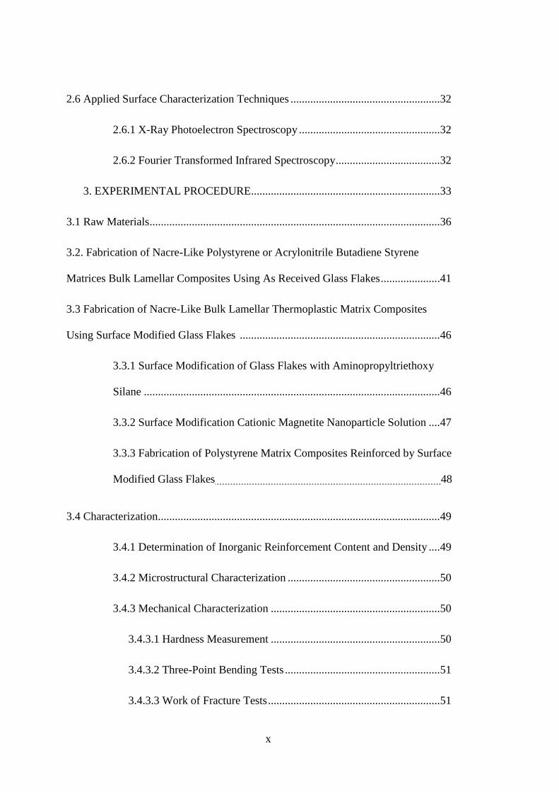
carbonate. In Figure 2.4, the comparison between aragonite and other
natural materials is presented. This specific strength graph shows that
aragonite has a remarkable specific strength. This helps to increase the
strength of the mother of pearl. However, as the natural composite materials
are combinations of different materials with varying interactions, they show
nonuniform strength distribution, even though the average strengths might
be considerably high.
11
Figure 2.4 Strength vs density of natural materials [4].
High strength and toughness of nacre is based on two main reasons which
are the hierarchical structure of mother of pearl and the intrinsic mechanical
characteristics of its inorganic and organic phases.
Mollusc shell is formed according to possible pathways to defend itself from
natural predators, and structure of this animal directly illustrates an armor
behavior. The outer part of the shell is the hardest part in the structure and
inner layer of the structure is tough meaning that it is one of the most
excellent armor to provide survival in the nature [4, 42]. The comparison of

12
toughness and modulus of the mollusc shell with those of the other natural
materials is given in Figure 2.5.
Figure 2.5 Comparison of mollusc shell with other natural materials in
terms of toughness and modulus [4].
Nacre has a complex mechanical behavior mechanism. Inorganic phase
nucleation, mineral bridging, nanoasperties, waviness, arrangement, organic
phase defolding play crucial role to get the unique properties. Detailed
information about all of these parameters are given in the following section.
13
2.4.1 Mechanical Properties of Nacre
Materials have some advantages and disadvantages according to their type
which are ceramics, metals and polymer. While investigating these materials
separately, each of them reveals superior behavior in terms of different
aspects. According to this division, polymers show more elastic behavior
than others while ceramics show more brittle behavior than others. Looking
at these general rules, nacre should reveal brittle behavior. Nevertheless,
although nacre contains large inorganic content, it demonstrates high
strength and toughness. Therefore, mechanical behavior of nacre is
composed of some exceptional mechanical cases.
The main advantage of nacre is its high compressive and tensile strength. In
addition to these it also shows high toughness and high elastic modulus
which depend on both the friction mechanism between aragonite platelets
and the waviness of platelets that are based on the arrangement of the
platelets and organic matrix behavior in the structure.
The investigation of nacre started with its behavior under tension. The
reason is that a probable attack in the natural medium of mother of pearl
directly causes tensile stress [42, 43]. Tensile properties of nacre are
different in dry and wet condition. According to the tensile test results of the
nacre, wet condition possesses superior mechanical properties than dried. In
Figure 2.6, tensile behavior of mother of pearl in two different physical
conditions is given. The main difference of nacre in tension arises from the
inorganic-organic phase interaction governed by sliding and friction
between aragonites. According to these results, dried nacre behaves like a
monolithic ceramic, however; hydrated nacre shows more inelastic behavior.
In tension, tablets slide and void content increases, and it is directly the
reason of failure in the structure.

14
Figure 2.6 (a) Stress-strain curve of nacre in tension along the tablets, (b)
schematic showing tablet sliding [42].
However, the tensile response reverses in shear. In tension most probably
caused by the organic matrix, hydrated nacre is higher in strength than the
dried nacre. While investigating the shear properties, dried nacre is stronger
than hydrated one. This mechanical result brings out the more complex
mechanical approach, the shear strength measurement reveals that the
organic bridging between tablets could provide a limited compensation in
compression and shear. The important mechanical features in the structure
are waviness and friction force between platelets that are higher in dried
condition.

15
Figure 2.7 (a) Stress – strain curves of simple shear (s-s) and shear
compression (s-c) responses of dried and hydrated nacre, (b) transverse
strain as function of shear strain [42].
All of these mechanical behaviors could be summarized in Figure 2.7. Nacre
is strong, tough and stiff and its shear, compression and bending response
can be observed in the following microstructural sketch.
Figure 2.8 Strength of nacre under different loading directions [44].
Mechanical behavior of the mother of pearl principally depends on the
toughening mechanism. Scientists investigate the nacre structure deeply, yet
(a) (b)

16
even they observe the nacre structure at nano scale, they could not
understand its mechanical behavior completely [6-8,18,42]. However in the
micrometer scale hierarchical structure of the inorganic phase and the
interaction of the organic phase with the inorganic phase show the excellent
properties in terms of mechanical strength [1, 2, 6-10, 16, 18, ,41-45]. The
toughening mechanism could be explained as when the load is applied to the
nacre, the sliding of platelets occurs. Normally, there should be huge friction
energy on weak platelets; however, because of the excellent interaction
between phases, the friction energy formed due to sliding is distributed.
Distribution of the energy behaves like work hardening mechanism so by
means of energy distribution applied load increases up to deforming the
structure. This work hardening mechanism in the polymeric structure leads
to whitening, and it is similar to metal work hardening behavior [2, 4, 6-10,
18, 41-45]. All of these mechanical processes form an efficient energy
dissipating system in the structure. In the sub- micrometer scale, the crucial
part is caused from the interaction between nano grains and the organic
phase. In this part, organic phase provides the resilience, and mechanism
due to the viscoelasticity of the organic component the energy dissipating
reaches to an efficient state [2, 4, 6-10, 18, 41-45]. At the last part of the
structure molecular domains are considered, and toughening mechanism in
this part is based on the refolding and unfolding of the molecular domains
[18, 42]. The refolding and unfolding of protein domains is observed when
load is applied. While the work hardening behavior is observed, the
refolding of domain happens; however, deformation is seen when protein
domain is unfolded. Consequently, this special toughening mechanism
induces the inspiration form nature.
2.4.2 Hierarchical Structure of Nacre
Hierarchical structure of nacre is another key point. This impressive
structural arrangement is also the reason behind the high mechanical
qualifications of nacre. The structure is defined as ‘brick and mortar’
architecture, and in Figure 2.9 brick and mortar structure of nacre can be

17
observed. The important approach about the nacre hierarchical structure is
called Voronoi model. Voronoi model explains the inorganic phase
nucleation based on a systematic. The nucleation starts between platelets
and according to the nucleated platelets, the shape of growing platelet
structure is like stairs [46]. Therefore, it causes a variation in mechanical
behavior. The mechanical behavior of the part of lap-streak platelets termed
as core is different than the other part [46-49].
Alignment of CaCO3 platelets, which possess brick and mortar structure,
provides the efficient mechanical result. In addition to this, it is an
explanation of how this high inorganic content composite material could
show extremely remarkable toughness and strength combination.
Figure 2.9 Hierarchical structure of nacre [50-54].
The special architecture of nacre leads to an efficient energy dissipating
system. This means that applying load on nacre energy could disperse in an
effective way, and it results in high loading capacity. Another crucial point
in this structure and in energy dissipating system of nacre is the interlocking
mechanism. Interlocking mechanism shows penetration of platelets between

18
each other, and this penetration between platelets is not a disadvantage; on
the contrary, it could be one of the best structural means to improve
mechanical properties. This beneficial interlocking behavior provides
distribution of energy leading to high toughness [9-18]. In Figure 2.10,
interlocking mechanism can clearly be seen.
Figure 2.10 Interlocking mechanisms in nacre [9].
Penetration of upper platelet to lower platelet results in a rotation between
platelets, and this interlocking mechanism occurs after the rotation. One of
the crucial reasons to get high toughness and strength values of mother of
pearl is to have this geometrical deformation. First deformation mechanism
in the interlocking platelets is observed in the organic phase of the structure.
The deformation can be calculated by applying load to these platelets in two
dimensions. It is like a shear mechanism so the first expected deformation is
observed between platelet and organic layer, as organic layer has lower
elastic modulus than platelets (Figure 2.11). This interfacial response is a
sign of the strength of the platelets as well. After the organic phase deforms
the interlocking zone damages, and these steps are directly related with each
other.

19
Scientists have been studying especially the effect of interlocking
mechanism of platelets on the strength of nacre. To demonstrate and clarify
interlocking mechanism some of the finite element method have been used,
and 3D observation could have been achieved from the modelling efforts
[9].
Figure 2.11 (a) Schematic illustration showing interlocks between platelets
of nacre showing that rotation of levels of platelets is essential for the
formation of platelet interlocks, (b) schematic illustration showing the
mechanism of loading through a cross-section cut across platelets and (c)
through the interlocks [9].
Scientists who study the simulation of nacre structure and effect of
interlocks investigate the two different conditions such as forming
interlocking between platelets and non-forming interlocking. It is on
essential investigation to understand the importance of interlocking.
Moreover, results showed that without interlocking formation, organic phase
in mother of pearl structure exhibits plastic behavior and in 14 MPa this
plastic deformation leads to the failure of nacre. When the interlocks are
(a)
(b)
(c)
20
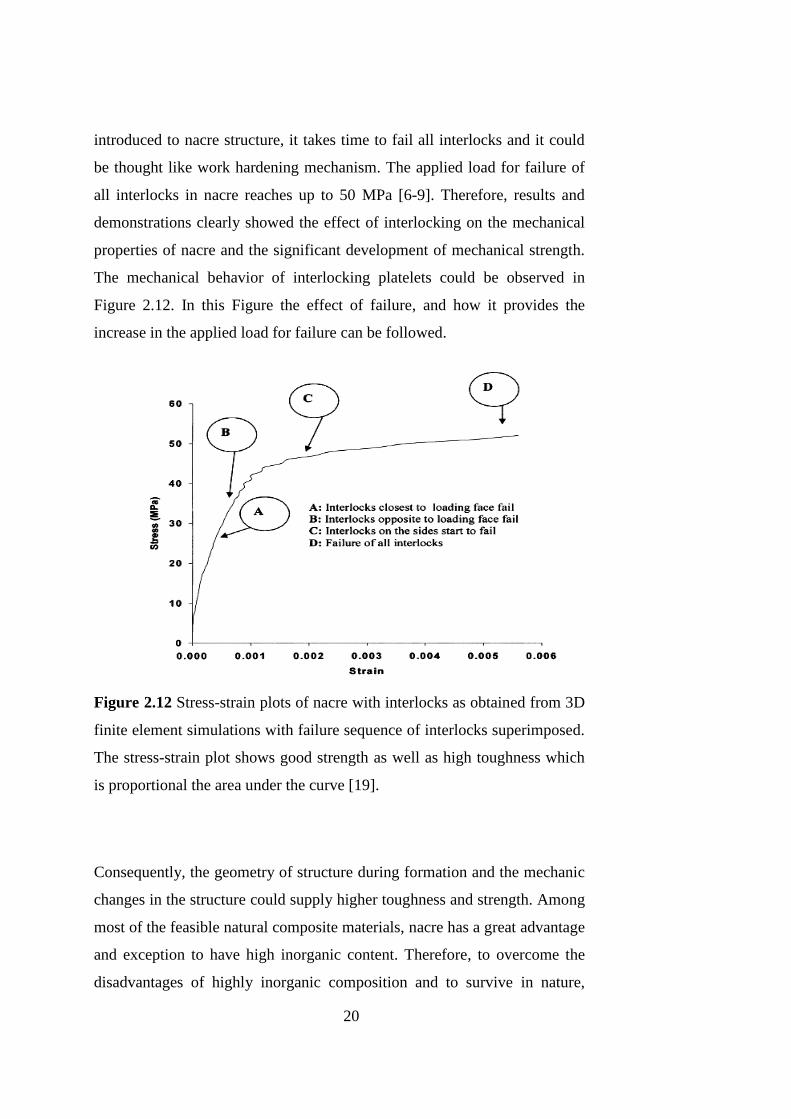
introduced to nacre structure, it takes time to fail all interlocks and it could
be thought like work hardening mechanism. The applied load for failure of
all interlocks in nacre reaches up to 50 MPa [6-9]. Therefore, results and
demonstrations clearly showed the effect of interlocking on the mechanical
properties of nacre and the significant development of mechanical strength.
The mechanical behavior of interlocking platelets could be observed in
Figure 2.12. In this Figure the effect of failure, and how it provides the
increase in the applied load for failure can be followed.
Figure 2.12 Stress-strain plots of nacre with interlocks as obtained from 3D
finite element simulations with failure sequence of interlocks superimposed.
The stress-strain plot shows good strength as well as high toughness which
is proportional the area under the curve [19].
Consequently, the geometry of structure during formation and the mechanic
changes in the structure could supply higher toughness and strength. Among
most of the feasible natural composite materials, nacre has a great advantage
and exception to have high inorganic content. Therefore, to overcome the
disadvantages of highly inorganic composition and to survive in nature,

21
nacre enhances its structural and mechanical properties. In recent years,
although influential explanations on the mechanical properties of mother of
pearl have been provided, still there are huge unknown aspects in the
mechanical properties of nacre. One of the understood mechanical behaviors
is the interlocking mechanism, and this mechanism acts like work hardening
mechanism rising the mechanical strength nacre.
2.4.3 Organic Phase in Mollusc Shell Structure
The organic phase of the nacre structure is one of the beneficial parts of this
extraordinary composite material. Organic part in the nacre structure is a
protein which is called β-chitin [1-6, 16 -56]. Although the organic content
in nacre is quite low when compared to inorganic content (95 vol %
aragonite -5 vol %protein), it has a very crucial role in the mechanical
behavior of the mother of pearl. The most important contribution of the
organic phase in the mechanical properties is elasticity. This small part in
the composite material and its contribution on elasticity leads to improved
mechanical properties. However, it is also effective on the stiffness.
According to Hooke’s Law, longitudinal strain decreases while increasing
transverse stress. Therefore, relationship between elasticity and Hooke’s law
could be satisfied. The result of this interaction shows that the organic
content increment at some point could show effective results in terms of
stiffness and poison’s ratio. Studies on organic phase of nacre structure and
simulations have shown that the organic phase ensures crucial results on
stiffness of material [8]. According to the results of strength and strain
values, the factors of mineral bridging and asperities have a crucial role in
mechanical behavior especially for fracture. While fracture happens in nacre
structure, mineral bridging and asperities behave as obstacles leading to
increased applied loads [18, 41]. In Figure 2.13, mineral bridging and
organic phase in nacre structure are shown clearly.

22
Figure 2.13 Various views of organic layer in nacre subjected to tensile test
(Field-emission SEM); (a, b) layers hanging between two tiles (marked with
arrow); (c, d) top view of tile surface with organic layer networks [41].
Organic phase in the structure creates elastic behavior, and it affects directly
the force distribution i.e. mechanical results of this impressive structure.
This small amount in mother of pearl leads to magnificent results in terms of
stiffness. In Figure 2.14 effect of organic matrix on modulus of elasticity of
nacre is shown.
(b) (a)
(c) (d)
23
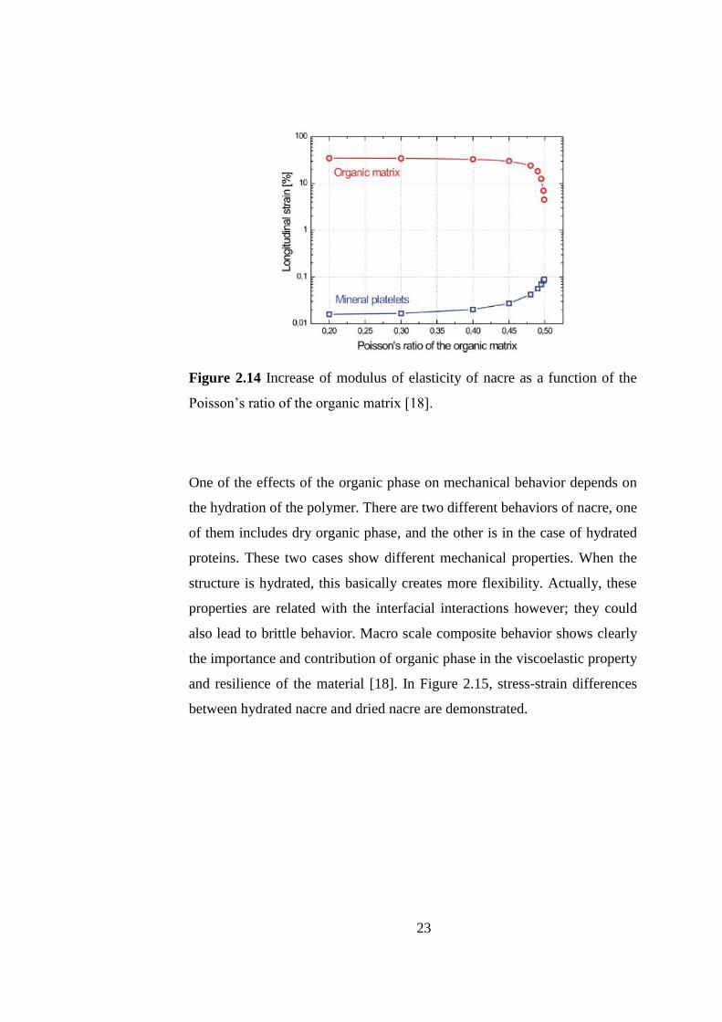
Figure 2.14 Increase of modulus of elasticity of nacre as a function of the
Poisson’s ratio of the organic matrix [18].
One of the effects of the organic phase on mechanical behavior depends on
the hydration of the polymer. There are two different behaviors of nacre, one
of them includes dry organic phase, and the other is in the case of hydrated
proteins. These two cases show different mechanical properties. When the
structure is hydrated, this basically creates more flexibility. Actually, these
properties are related with the interfacial interactions however; they could
also lead to brittle behavior. Macro scale composite behavior shows clearly
the importance and contribution of organic phase in the viscoelastic property
and resilience of the material [18]. In Figure 2.15, stress-strain differences
between hydrated nacre and dried nacre are demonstrated.

24
Figure 2.15 (a) Stress-strain curves measured in tensile test of dried and
hydrated nacre. The insets illustrate the deformation behavior during
loading, (b) deformation behavior in the work-hardening stage in the stress-
strain curve (SEM image). Platelets are progressively pulled out in an
accumulative manner [18].
One of the interesting parts in nacre behavior about organic phase is
observed in the nanoscale. In this part, nano grain and organic bridging are
main part of the structure, while deep in the structure molecular toughening
mechanism is operative. This mechanism is composed of folding and
unfolding of proteins. These folding and unfolding reinforces the work
hardening mechanism, so it has control on toughness increment directly
[18]. Mechanical effects of folding and unfolding are shown in Figure 2.16.

25
Figure 2.16 Schematic diagram of deformation behavior of proteins with
modular structures [8].
In Figure 2.17, there is scale about nacre structure and observation of
organic phase. In this chart, structure of nacre, toughening mechanism of
nacre and the role of organic phase has been clarify.
Figure 2.17 Hierarchical toughening mechanism of nacre. Toughening can
be classified according to the operating dimension, from an inter-platelet
mechanism operating at the sub micrometer scale, to an intra-platelet
mechanism of the order of several tens of nanometers, down to individual
organic molecules (nm scale) [18].
26
2.4.4 Possible Fabrication Methods of Composite Materials Inspired by
Nacre
After the discovery of superior behavior in terms of high strength and
toughness of nacre, scientists started to look at possible fabrication methods
for composite materials inspired by nacre. Investigations of nacre
hierarchical structure and mechanical behavior have triggered the efforts to
develop some fabrication pathways. Some of these production methods are
well-known now such as layer by layer (LBL), Self-Assembly, Thin Film
Coating, Hot press Assisted Slip Casting (HASC), Tape Casting, Magnetic
Field Interaction etc. These methods are being discussed below showing the
production of nacre like architecture with achieved mechanical resullts.
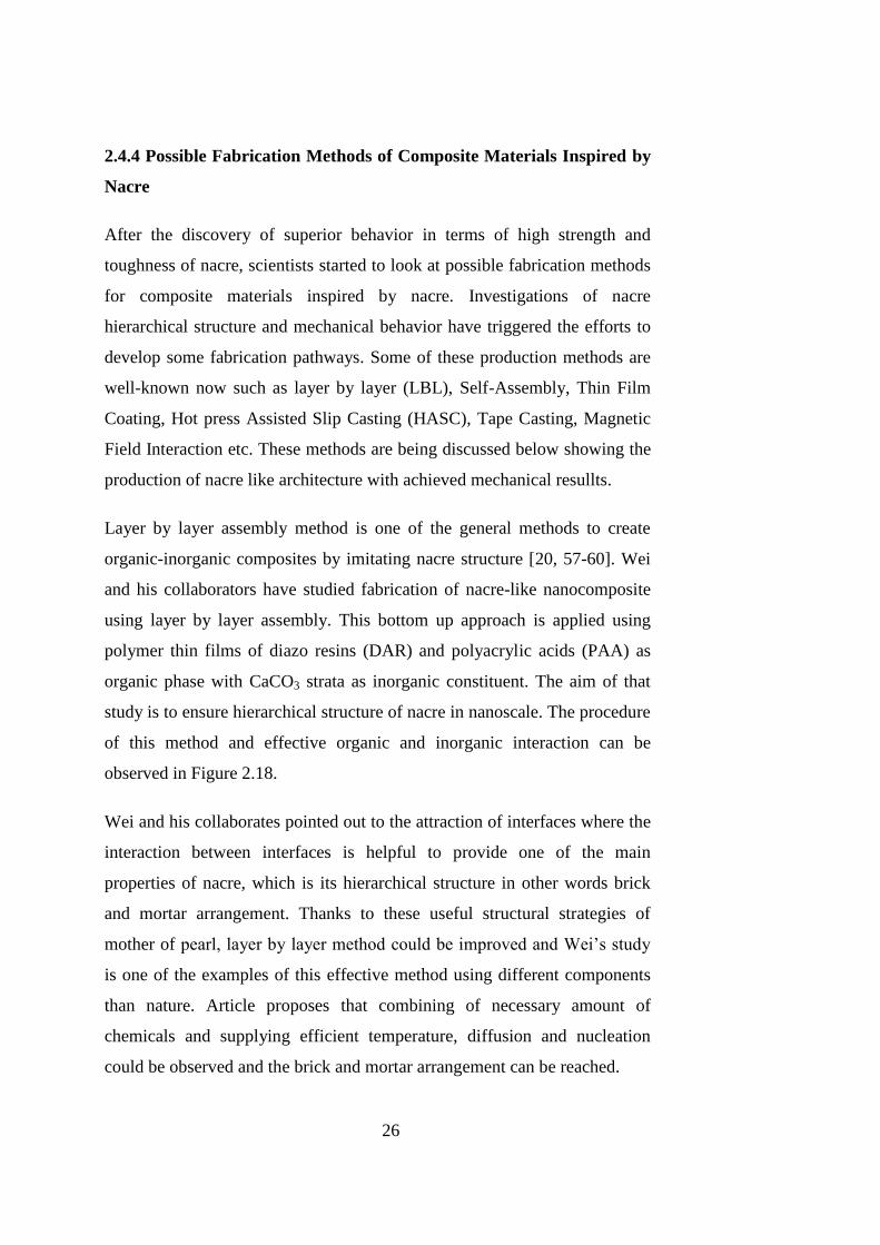
Layer by layer assembly method is one of the general methods to create
organic-inorganic composites by imitating nacre structure [20, 57-60]. Wei
and his collaborators have studied fabrication of nacre-like nanocomposite
using layer by layer assembly. This bottom up approach is applied using
polymer thin films of diazo resins (DAR) and polyacrylic acids (PAA) as
organic phase with CaCO3 strata as inorganic constituent. The aim of that
study is to ensure hierarchical structure of nacre in nanoscale. The procedure
of this method and effective organic and inorganic interaction can be
observed in Figure 2.18.
Wei and his collaborates pointed out to the attraction of interfaces where the
interaction between interfaces is helpful to provide one of the main
properties of nacre, which is its hierarchical structure in other words brick
and mortar arrangement. Thanks to these useful structural strategies of
mother of pearl, layer by layer method could be improved and Wei’s study
is one of the examples of this effective method using different components
than nature. Article proposes that combining of necessary amount of
chemicals and supplying efficient temperature, diffusion and nucleation
could be observed and the brick and mortar arrangement can be reached.

27
Figure 2.18 Schematic illustration for the fabrication of artificial nacre (a)
LBL, self-assembly of DAR/PAA multilayered film via the alternating
deposition method; (b) preparation of CaCO3 nanolaminated structure on the
DAR/PAA multilayered films by CO2 gas diffusion method; (c) preparation
of the multilayer organic/inorganic hybrid composite by alternately
repeating steps (a) and (b) [60].
Self-assembly is one of the common processing methods to reach nacre like
architecture [19, 61-63] .This technic is one of the examples to provide one
of the main properties of mother of pearl, which is its hierarchical structure.
After the investigation of this excellent arrangement as mentioned above,
the crucial part is control the interaction of two chemically different phases.
There are various ways and chemical reactions, to control this interaction.
One of them is very common, and this is widely used in industry which is
silane treatment. Bonderer et al. used this chemical treatment to get superior
mechanical properties.
Silane is a different type of chemical. It is called as coupling agent
generally, and the main property of this coupling agent is to supply the

28
interfacial bonding between inorganic and organic phases. It behaves like a
bridge so its composition directly affects the mechanical behavior of the
material. Bonderer et al. explained the contribution of the silane application
on mechanical results. Bonderer’s study showed that while using alumina
platelets with CaCO3 and applying silane treatment on them, the effect of
reinforcement on the mechanical properties could be observed clearly [61].
In Figure 2.19, silane application on alumina platelets and the procedure
applied in that study is shown.
Figure 2.19 Bottom up colloidal assembly of multilayered hybrid films.
Surface modified platelets are assembled at the air-water interface to
produce a highly oriented layer of platelets after ultrasonication. The 2D
assembled platelets are transferred to a flat substrate and afterwards covered
with a polymer layer by conventional spin coating [61].
This study demonstrated that the artificial bioinspired material could be
reach relatively to high elastic modulus which is 10 GPa for alumina
platelet-chitosan films, being comparable to those of with teeth and bone.
Another remarkable result is that artificial film has approximately 300 MPa
tensile strength which is quite high for a polymer based artificial material.
29
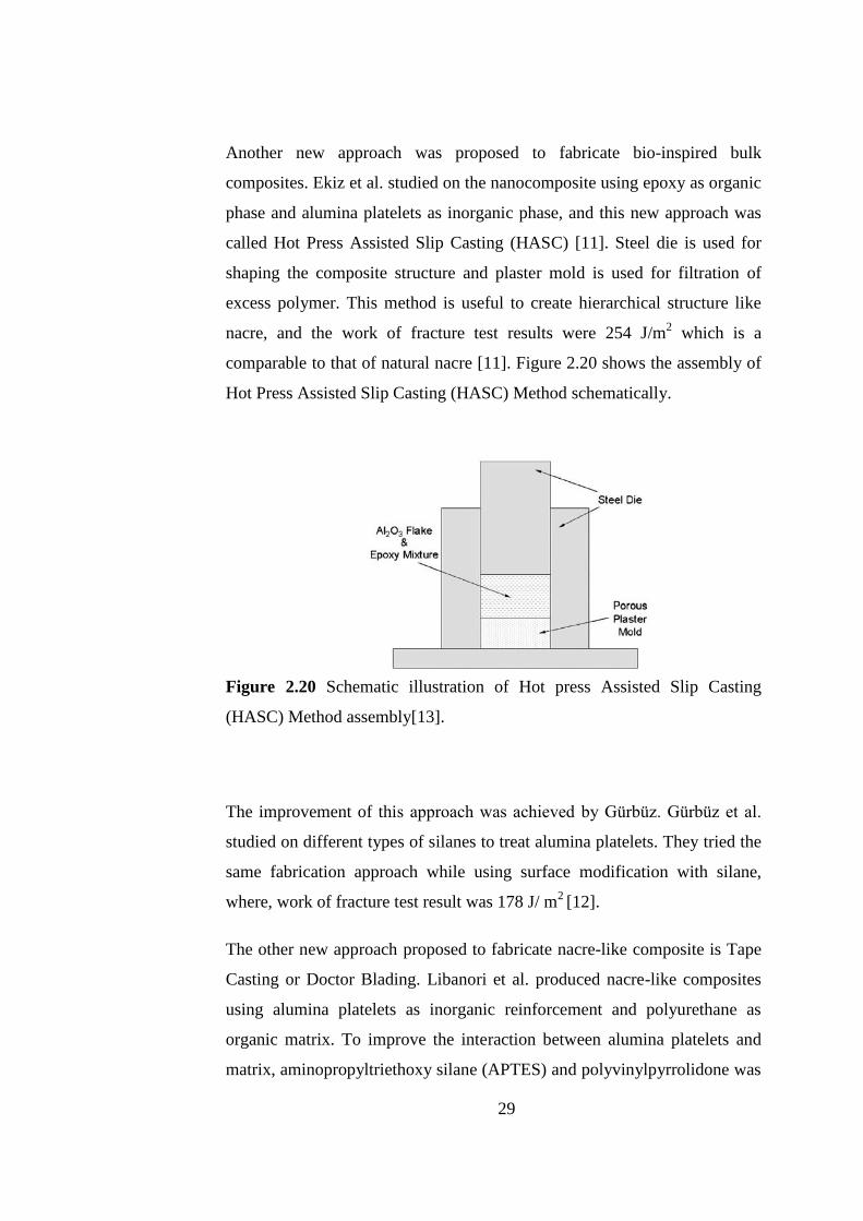
Another new approach was proposed to fabricate bio-inspired bulk
composites. Ekiz et al. studied on the nanocomposite using epoxy as organic
phase and alumina platelets as inorganic phase, and this new approach was
called Hot Press Assisted Slip Casting (HASC) [11]. Steel die is used for
shaping the composite structure and plaster mold is used for filtration of
excess polymer. This method is useful to create hierarchical structure like
nacre, and the work of fracture test results were 254 J/m2 which is a
comparable to that of natural nacre [11]. Figure 2.20 shows the assembly of
Hot Press Assisted Slip Casting (HASC) Method schematically.
Figure 2.20 Schematic illustration of Hot press Assisted Slip Casting
(HASC) Method assembly[13].
The improvement of this approach was achieved by Gürbüz. Gürbüz et al.
studied on different types of silanes to treat alumina platelets. They tried the
same fabrication approach while using surface modification with silane,
where, work of fracture test result was 178 J/ m2 [12].
The other new approach proposed to fabricate nacre-like composite is Tape
Casting or Doctor Blading. Libanori et al. produced nacre-like composites
using alumina platelets as inorganic reinforcement and polyurethane as
organic matrix. To improve the interaction between alumina platelets and
matrix, aminopropyltriethoxy silane (APTES) and polyvinylpyrrolidone was

30
used in this study, where the main point was to reinforce reinforced the
matrix with laponite. Mechanical results revealed that thermoplastic matrix
reinforced by laponite showed increase in strength and elastic modulus
substantially, being 91.7 MPa and 6.97 GPa, respectively [64].
One of the new approaches to supply hierarchical structure of mother of
pearl is to align flakes with magnetic and mechanic stimulus. Nonmagnetic
flakes can interact with the magnetic field by attaching magnetite particles
on their surface. Magnetite particle attached alumina platelets were used as
inorganic phase and epoxy matrix was used as organic phase. Aligned
platelets were put into epoxy matrix, and mechanical results showed that
this magnetic alignment causes an increase in flexural modulus being 1.4
fold higher than that of the as cast composite [15]. Related procedure is
shown in Figure 2.21. The drawback in this study was the need to a
relatively strong magnetic field.
Figure 2.21 Processing route for the production of platelet-reinforced
composites with tailored architectures using mechanical and magnetic
stimuli. Solenoids are used to keep the alignment of the ultrahigh magnetic
response (UHMR)-platelets while curing the composites inside an oven at
60°C [15].
31
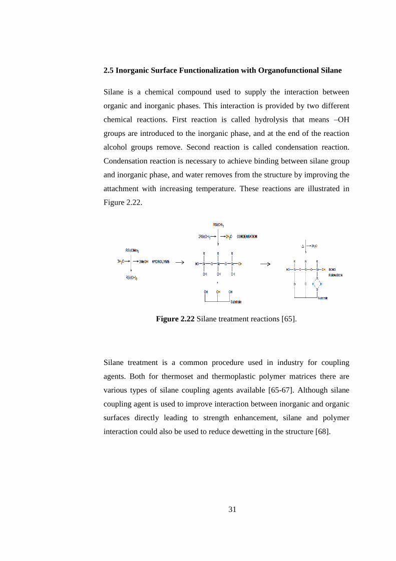
2.5 Inorganic Surface Functionalization with Organofunctional Silane
Silane is a chemical compound used to supply the interaction between
organic and inorganic phases. This interaction is provided by two different
chemical reactions. First reaction is called hydrolysis that means –OH
groups are introduced to the inorganic phase, and at the end of the reaction
alcohol groups remove. Second reaction is called condensation reaction.
Condensation reaction is necessary to achieve binding between silane group
and inorganic phase, and water removes from the structure by improving the
attachment with increasing temperature. These reactions are illustrated in
Figure 2.22.
Figure 2.22 Silane treatment reactions [65].
Silane treatment is a common procedure used in industry for coupling
agents. Both for thermoset and thermoplastic polymer matrices there are
various types of silane coupling agents available [65-67]. Although silane
coupling agent is used to improve interaction between inorganic and organic
surfaces directly leading to strength enhancement, silane and polymer
interaction could also be used to reduce dewetting in the structure [68].
32
2.6 Applied Surface Characterization techniques
2.6.1 X-Ray Photoelectron Spectroscopy
X-Ray photoelectron spectroscopy (XPS) is a quantitative and qualitative
analytical technique. XPS provides information about surface elemental
composition and chemical and electronic state. This technique is used for
determining all elements other than hydrogen and helium [69]. The analyzed
depth of the sample in XPS technique is on the order of 5-10 nm [70].
XPS technique is based on the photoelectric effect. Each surface atom has
core electrons, and for all surface atoms there is a characteristic binding
energy. XPS technique makes use of the removal of these electrons where
the ionization energy is recorded. Therefore, this technique mainly
determines the surface chemical composition of specimens by detecting the
kinetic energy of the ejected photoelectrons from surface atoms.
Photoelectron counts vs binding energy graph gives the information about
elements present at the very surface of the material [71].
2.6.2 Fourier Transformed Infrared Spectroscopy
Fourier Transformed Infrared Spectroscopy (FTIR) is a spectroscopic
technique used to determine chemical compounds. FTIR mainly depends on
the vibration of atoms that changes the binding of elements in different
directions. Molecular vibrations should be detected by FTIR to determine
the presence of chemical compounds. Therefore, molecular geometry is
important [72-73].
The vibration of atoms results in the oscillation of electric charge, and
oscillating molecular dipole interacts with the electromagnetic radiation
being put into resonance. This behavior provides determination of chemical
compounds. [72-73].

33
CHAPTER 3
EXPERIMENTAL PROCEDURE
In the scope of this study, fabrication of bio-inspired nacre-like bulk
lamellar composite materials will be investigated containing both low and
high aspect ratio glass flakes as the reinforcing phase and fabricated by
‘‘Hot press Assisted Slip Casting Procedure’’(HASC), ‘‘Tape Casting’’(TC)
and ‘‘Magnetic Field Assistance’’ techniques. One of the significant points
in this study is the investigation of different thermoplastic polymers as the
matrix material in composite structures.
In this chapter, hot press assisted slip casting procedure, tape casting and
magnetic field assistance procedures were explained where raw materials
were also identified. Microstructural and mechanical characterization
methods utilized were demonstrated. Fabrication procedures applied
throughout this study are summarized in the form of a flow chart and
presented in Figure 3.1.

34
Raw Material: Glass Flakes (GF750-GF003)
Surface Functionalization of flakes (APTES)
pH adjustment & Addition of silane
Addition of flakes &
Stirring
Filtration & Drying
As-received Flake Mixture Surface Treated Flake
Mixture
Mixing the flakes with polystyrene and acrylonitrile butadiene
styrene solution seperately
As Casting Tape Casting Tape Casting As Casting
& & & &
Hot Pressing Hot Pressing HASC HASC
Pouring the
mixture on glass
surface & wait
until drying
Dried simple mixed film like
structure placed into steel die
Hot Pressing
Pouring the
mixture on
glass surface&
wait until
drying
Scraping the mixture via
Doctor Blade on glass surface
& wait until drying
Casting of the plaster into the
Steel die
&
Drying
Dried taped film like structure
placed into steel die
Hot Pressing & Filtering the excess resin
(a)

35
Figure 3.1 Flow chart of the fabrication procedures applied in this study (a)
Hot-Pressing based methods, (b) Magnetic Field Assistance based methods.
Magnetite Assistance Based Method
Surface Modification of flakes with cationic magnetite
nanoparticle solution
Addition of necessary amount of the cationic magnetite
nanoparticle solution to the basal solution
Addition of glass flakes
Filtration & Drying
Surface Modified Flakes
Placed surface treated flakes on a strong magnet in order to align
vertically
Addition of the polymer solution drop by drop on the glass flakes
mass to supply matrix
Wait until drying
Dried film like structure placed into steel die
die
Hot Pressing
Surface Functionalization of flakes with APTES
pH adjustment & Addition of silane to the solvent
Addition of flakes & Stirring
Filtration & Drying
Surface treated flakes
(b)

36
3.1 Raw Materials
Bio-inspired nacre-like bulk lamellar thermoplastic polymer matrix
composite materials were fabricated using polystyrene and acrylonitrile
butadiene styrene as organic matrix phase and glass flake as inorganic
reinforcing phase. Indication and aspect ratio of two different types of glass
flakes used are demonstrated in Table 3.1. One of the inorganic phases used
in this dissertation is called as unmilled glass flake and the other one is
micronized, where these differences result from the production methods of
the glass flakes. Particle size distribution of micronized glass flakes (GF
003) is such that 2% or less is > 150µm, 10% or less is between 50-150 µm
and 88% or more is < 50 µm. The average diameter of GF 003 micronized
glass flakes is less than 50 µm and the thickness of these flakes is 2.3-3.3
µm (Glass Flake Ltd., Leeds, UK). Particle size distribution of unmilled
glass flakes (GF 750) is such that 80% or more is 1700- 150 µm and 20 % or
less is <150 µm. The average diameter of unmilled glass flakes GF 750 is
between 1700-150 µm and the thickness of these flakes is between 5.5-9.5
µm (Glass Flake Ltd., Leeds). Both of the glass flakes are made of C type
glass as a result of which they are extra corrosion resistant. Microstructural
observation of these glass flakes has been conducted using scanning electron
microscope (SEM), and the SEM images are given in Figure 3.1. The
chemical content of these glass flakes are shown in Table 3.2.
Table 3.1 Properties of glass flakes used in this dissertation.
Indication Type Morpholog Density (g/cm3) Aspect Ratio
GF 003 Micronized Flake 2.6 ~15-20
GF 750 Unmilled Flake 2.6 ~73

37
Figure 3.2 Scanning electron microscope images of a) Micronized glass
flakes GF 003, b) Unmilled glass flakes GF 750.
Table 3.2 Chemical analysis of the glass flakes.
Chemical Analysis (GF003 and GF750)
SiO2 64-70%
K2O 0-3%
B2O3 2-5%
ZnO 1-5%
Na2O 8-13%
MgO 1-4%
CaO 3-7%
Al2O3 3-6%
TiO2 0-3%
(a) (b)

38
Fabrication of nacre-like composite materials was conducted using
thermoplastic polymers as matrix materials. These thermoplastic polymers
are Polystyrene (PS) and Acrylonitrile Butadiene Styrene (ABS). Initially
the polymers had granular form and the matrix formation from these
polymers were achieved by solving efficient amount of polymers granules in
a proper solvent. Typical properties of these thermoplastic polymers was
obtained by the help of gel permeation chromatography, and the number
average molecular weight of PS was determined to be 64946 g/mole while
that of the ABS was determined to be 28309 g/mole. Polymer solutions were
prepared using chloroform and dimethyl formamide (99% Merck, Sigma-
Aldrich, USA) as solvents for PS and ABS, respectively.
The reason of choosing PS and ABS as thermoplastic polymer matrices was
that there are quite a number of common industrial applications of these
polymers, and they could be comparable with the results of other studies on
nacre-like composites especially having thermoset matrix. In this study
crystalline polystyrene and amorphous acrylonitrile butadiene granules were
used as initial polymer materials. The difference of polymer structure in
crystalline form of PS and monomer of PS can be seen in Figure 3.3.
Furthermore, ABS is a terpolymer which means that it is a combination of
three different chemical units. These chemicals units and ABS structure are
shown in Figure 3.4 and Figure 3.5, respectively.

39
a)
CH2CH
CH2
n
b)
Figure 3.3 Polystyrene a) structure of monomer and polymer b) structure of
syndiotactic Polystyrene (PS) in highly crystalline form.
Styrene(Monomer) Repeating Unit Polystyrene
CH2
CH
CH2
CH
CH2
CH
CH2
CH
CH2
CH
CH2

40
N
CH2
CH2CH2
CH2
Figure 3.4 Different chemical units in ABS.
N
x y z
Figure 3.5 Chemical structure of Acrylonitrile Butadiene Styrene
(ABS).
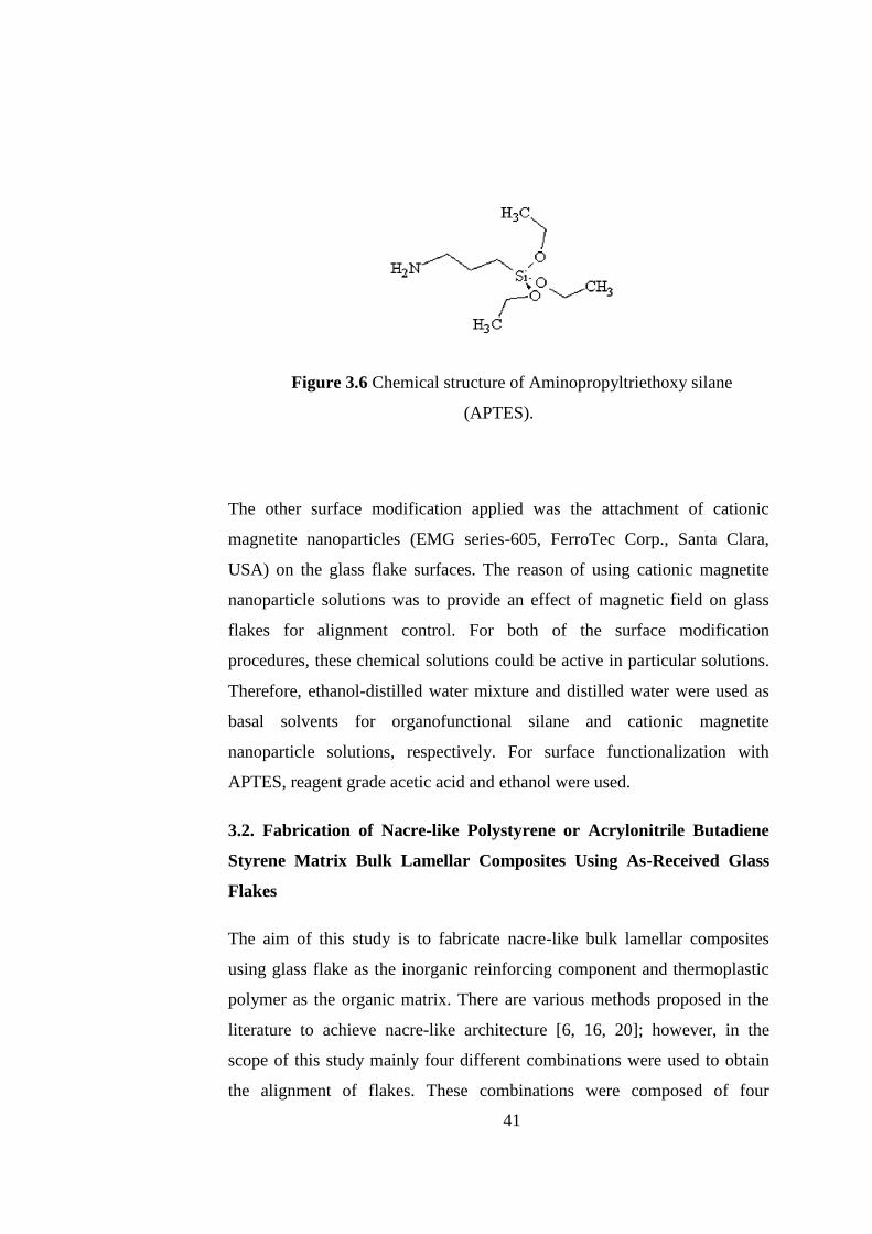
In this study, glass flakes surfaces were also modified according to the
processes described below. Two different types of surface applications were
applied. One of them is the application of a coupling agent which is called
silane. There are different types of silanes used as coupling agents, where in
this study an organofunctional silane, namely aminopropyltriethoxy silane
(APTES, Silquest A-1100, Momentive Performance Materials Inc., Ohio,
USA) was used. The aim of using this coupling agent was to achieve a better
bonding between the organic and inorganic phases of the composites.
Chemical structure of APTES is given in Figure 3.6.
Acrylonitrile 1-3
butadiene
Styrene
41
Figure 3.6 Chemical structure of Aminopropyltriethoxy silane
(APTES).
The other surface modification applied was the attachment of cationic
magnetite nanoparticles (EMG series-605, FerroTec Corp., Santa Clara,
USA) on the glass flake surfaces. The reason of using cationic magnetite
nanoparticle solutions was to provide an effect of magnetic field on glass
flakes for alignment control. For both of the surface modification
procedures, these chemical solutions could be active in particular solutions.
Therefore, ethanol-distilled water mixture and distilled water were used as
basal solvents for organofunctional silane and cationic magnetite
nanoparticle solutions, respectively. For surface functionalization with
APTES, reagent grade acetic acid and ethanol were used.
3.2. Fabrication of Nacre-like Polystyrene or Acrylonitrile Butadiene
Styrene Matrix Bulk Lamellar Composites Using As-Received Glass
Flakes
The aim of this study is to fabricate nacre-like bulk lamellar composites
using glass flake as the inorganic reinforcing component and thermoplastic
polymer as the organic matrix. There are various methods proposed in the
literature to achieve nacre-like architecture [6, 16, 20]; however, in the
scope of this study mainly four different combinations were used to obtain
the alignment of flakes. These combinations were composed of four
42
different techniques which are As Casting (AC), Tape Casting (TC), Hot
Pressing (HP) and lastly Hot press Assisted Slip Casting (HASC).
Combinations of these techniques were investigated to determine especially
the effect of TC and HASC methods on glass flake alignment. On the other
hand, AC and HP methods were used to differentiate TC and HASC
processes and to demeonstrate the variation in the alignment of flakes
deeply. Consequently, four different types of combinations used in this
study can be indicated as AC+HASC, AC+HP, TC+HASC, TC+HP.
For all of these methods, there was a common procedure to prepare the
polymer solutions containing 10 g of the corresponding polymer granules.
Polystyrene and acrylonitrile butadiene styrene granules were dissolved in
efficient solvents that are chloroform and dimethyl formamide, respectively.
Proper amount of polymer solutions were prepared with 80 ml of either of
the solvents and 10 g of the corresponding polymer granules.
Following the preparation of the polymer solutions, 30 ml from each
polymer solution was taken and mixed with 3 g of glass flakes mixture to
prepare the suspensions which were used in as casting or tape casting
procedures. 3 g of glass flakes was determined to be the efficient flake
amount. A mixture of two different types of glass flakes with different sizes
was used throughout this study as the reinforcing phase. This glass flake
mixture contained 80 wt% GF 750 and 20 wt% GF 003. The mixture
content was determined by trying different glass flake proportions changing
from 100 wt% GF 750 to 0 wt% GF 750 where the mixtures were observed
to reveal a microstructure similar to that of nacre structure. Later on, mixture
of flakes was added to 30 ml polymer solution and stirred with magnetic
stirrer for approximately 5 min. Finally, as casting or tape casting procedure
was applied.
After mixing step the mixture was poured on a glass surface which was kept
in as-cast condition in the case of as casting or was doctor bladed in the case
of tape casting. For the as casting method, the mixture poured on the glass

43
surface has been kept approximately one day in the as-cast condition to dry.
After that, dried film like structure was removed from the glass surface by
cutting square shaped specimens using a fresh knife.
The second method used was tape casting. Tape casting process in other
words knife coating or Doctor Blading is based on scraping a particle
containing mixture via blade on a substrate. There is a blade in tape casting
machine which is called doctor blade, and there are calipers to adjust the
height of the blade from the substrate to control the final thickness of the
tapes. In this particular case, polymer solution-glass flake mixture was
poured in the tape casting chamber after adjusting the blade to 50 µm height,
and then the chamber was moved with a speed of 20 cm/s to scrape the
mixture on the glass substrate surface. Scraped tapes were kept on the glass
substrate for several days to dry, after which they were removed by cutting
them as square shaped specimens using a fresh knife. Schematic
representation of the tape casting equipment and the applied procedure are
shown in Figure 3.7.
The two initial shaping methods (AC and TC) were followed by two other
methods called HASC and HP to consolidate dried initial films or tapes to
form bulk composites. Both AC and TC procedures were followed by
putting the films or tapes into a steel die for compaction. A 20 x 20 mm
square cross sectioned steel die has been used as a mold for the processing
of the composites. After placing dried films or tapes into the steel die HASC
or HP processes were applied on both as-cast or tape cast specimens both of
which included application of heat and pressure simultaneously.
In the case of the HASC process, the lower exit of the steel die was closed
with plaster as a porous filter through which excess liquid resin can flow
under the action of the applied pressure, and hence can be drained while
providing alignment to the glass flakes with their basal surfaces
perpendicular to the hot-pressing direction. Porous plaster was cast into the
lower exit of the square cross sectioned steel die. Following the melting of
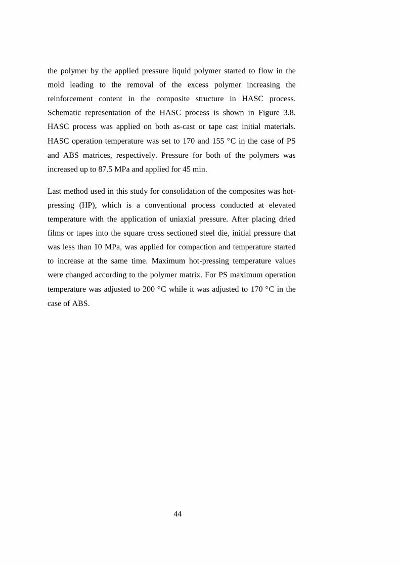
44
the polymer by the applied pressure liquid polymer started to flow in the
mold leading to the removal of the excess polymer increasing the
reinforcement content in the composite structure in HASC process.
Schematic representation of the HASC process is shown in Figure 3.8.
HASC process was applied on both as-cast or tape cast initial materials.
HASC operation temperature was set to 170 and 155 C in the case of PS
and ABS matrices, respectively. Pressure for both of the polymers was
increased up to 87.5 MPa and applied for 45 min.
Last method used in this study for consolidation of the composites was hot-
pressing (HP), which is a conventional process conducted at elevated
temperature with the application of uniaxial pressure. After placing dried
films or tapes into the square cross sectioned steel die, initial pressure that
was less than 10 MPa, was applied for compaction and temperature started
to increase at the same time. Maximum hot-pressing temperature values
were changed according to the polymer matrix. For PS maximum operation
temperature was adjusted to 200 C while it was adjusted to 170 C in the
case of ABS.
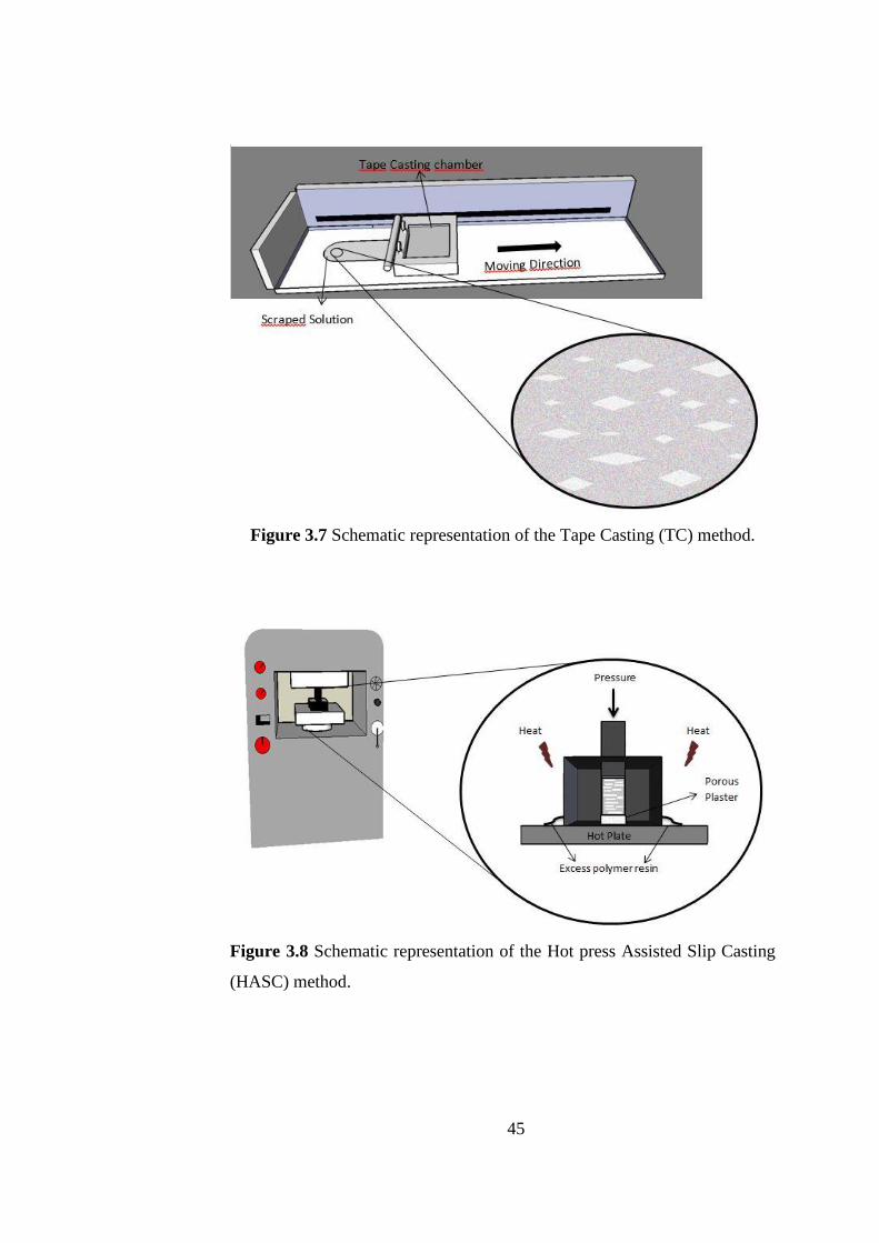
45
Figure 3.7 Schematic representation of the Tape Casting (TC) method.
Figure 3.8 Schematic representation of the Hot press Assisted Slip Casting
(HASC) method.

46
3.3 Fabrication of Nacre-Like Bulk Lamellar Thermoplastic Matrix
Composites Using Surface Modified Glass Flakes
Two different surface modification procedures the details of which were
explained below are used to modify the glass flake surfaces in this study.
For the fabrication of the nacre-like bulk lamellar PS matrix composites
reinforced by these surface treated glass flakes AC+HASC process
combination was chosen among the four previously described combinations,
as it has been determined to reveal the best microstructural architecture
along with the maximum mechanical property enhancement.
3.3.1 Surface Modification of Glass Flakes with Aminopropyltriethoxy
Silane
To observe convenience and interfacial bonding between the inorganic and
organic components of the desired composites, surfaces of the glass flakes
were modified by functionalization using a silane coupling agent. Surface
functionalization procedure was applied in a basal solution based on reagent
grade acetic acid and ethanol. In this procedure solution should have specific
pH range to provide hydrolysis reaction that is first compulsory reaction for
silane application. After providing appropriate pH value (4.5-5.5), silane
solution was added to the basal solution and stirred on a magnetic stirrer for
90 min. Then, glass flakes were added to the resulting clear solution and
mixed for an additional 30 min. Following this, the excess solution was
filtered off using a filter paper. Second and last compulsory reaction of the
silane treatment is the condensation which was supplied by keeping the
filtered glass flakes in a drying oven at 120 C for 60 min. Detailed
representation of the silane treatment reactions are shown in Figure 3.9.

47
Hydrolysis Reaction
CH3OH
OH2+Si
OO
O
CH3
CH3
CH3
NH2
Si
OH
OH
OH
NH2 +
Condensation Reactions
+Si OHNH2
O
Si OHNH2
OH
O
Si OHNH2
OH
Si OHNH2
OH
OH
Si OHNH2
OH
OH
Si OHNH2
OH
OH
OH2
OH
OH
OH
OH
OH
OH ++OH
Figure 3.9 Silane treatment reactions.
3.3.2 Surface Modification with Cationic Magnetite Nanoparticle
Solution
Cationic magnetite nanoparticle solution is a ferromagnetic water based
solution. As solution is cationic, pH of the solution is critical. For magnetite
nanoparticle attachment only GF 750 type glass flakes were used. The basal
solution for attachment of magnetite nanoparticles was distilled water
(pH≈6.5). By adding 5 g of glass flakes into 80 ml distilled water, the
solution pH reached up to 9.5 which is enough to attach magnetite
nanoparticles from the cationic solution. 0.5µl (ca. 20 vol%) of the cationic
nanoparticle suspension was added to the basal solution containing the glass
Aminopropyltriethoxy
silane
Glass
Surface
Glass
Surface

48
flakes. The mixture was stirred on a magnetic stirrer for 90 min after which
the excess liquid was filtered off using filter paper. At this step, the filtered
excess solution was colorless; however, the color of the glass flakes turned
into brown. After the filtration, magnetite nanoparticle attached flakes were
put in an oven to dry at 120 C for 1.5 h.
Magnetite nanoparticle attached glass flake surfaces were additionally
treated with silane application. After drying magnetite nanoparticle attached
glass flakes were added to the prescribed basal solution that was prepared
for organofunctional silane application. pH range to activate silane and the
amount of silane were not changed. After addition of the glass flakes, the
mixture was stirred for 60 min and the excess solution was filtered off. After
the filtration, double surface treated glass flakes were kept in a drying oven
at 120 C for 60 min.
3.3.3 Fabrication of the Polystyrene Matrix Composites Reinforced by
Surface Modified Glass Flakes
There are various methods to mimic mollusc shell architecture. One of
newest methods to fabricate nacre-like structure includes assisting the
inorganic flake alignment by magnetic field application. The scope of this
study is to achieve brick and mortar architecture with the help of various
pathways to fabricate nacre-like bulk lamellar thermoplastic matrix
composites. In this context, magnetic field application to magnetite
nanoparticle attached glass flakes was one of the alignment methods studied
within this dissertation.
To supply the effect of magnetic field on the non-magnetic inorganic
reinforcements, magnetite nanoparticles were attached on glass flake
surfaces were modified with cationic magnetite nanoparticle solution.
Magnetite nanoparticle attached and also additionally silane treated glass
flakes were placed on a niobium hard magnet to orientate them with the
magnetic field being their basal surfaces perpendicular to the magnet

49
surface. The polymer matrix was provided by pouring the prescribed
polystyrene solution on the magnetically oriented glass flakes carefully and
keeping them on the magnet until the solvents evaporate to obtain complete
drying. The important point in this application is the area of magnet surface.
Magnetite nanoparticle attached glass flakes should properly cover the
magnet surface to effectively couple with the magnetic field. Hence, just 1 g
of glass flakes was put on the surface of the magnet and three different
matrix amounts was obtained by adding three different amounts of the
polymer solution as 5, 6 and 9 ml. Following drying the film like structure
was removed from the magnet and placed into the aforementioned steel die
and hot pressing procedure was applied to three different matrix amount
containing composites as described previously.
3.4 Characterization
3.4.1 Determination of Inorganic Reinforcement Content and Density
The determination of the inorganic reinforcement content of the composites
was conducted by burning off at least three specimens fabricated by each
method at 600°C for 60 min under air atmosphere applying a heating rate of
4°C/min. Thermoplastic polymers, PS and ABS were removed by
combustion and the residues were used to calculate inorganic content for
each composite. Volume percentage of the inorganic phase (VR %) was
determined using the following equation;
100)1(
%
MRRR
MRR
WW
WV
(3.1)
where WR is determined weight of the reinforcement, ρR is the theoretical
density of the glass flakes and ρM is the theoretical density of the
corresponding polymer matrix.
Densities of the specimens were determined by means of Archimedes’
principle. Equation 3.2 describes Archimedes’ principle. By the help of an
50
immersion medium that is water and measuring dry weight (Wdry), saturated
weight (Wsat) and suspension weight (Wsus) of the specimen, density of the
fabricated composites was calculated.
sussat
dry
WW
W
(3.2)
3.4.2 Microstructural Characterization
Specimens cut from composites fabricated by different process
combinations were mounted in epoxy resin. To get an appropriate specimen
surface, specimens were ground with silicon carbide emery papers according
to metallographic surface preparation standards. Ground specimen surfaces
were polished with 1 μm and 0.3 μm diamond suspensions. Fracture
surfaces of the three-point bending specimens and as polished composite
surfaces were examined for microstructural characterization with the help of
a scanning electron microscope (SEM) (FEI Nova Nano SEM 430).
3.4.3 Mechanical Characterization
Mechanical characterization of the fabricated nacre-like bulk lamellar
composites was executed by hardness, three-point bending and work of
fracture tests (WOF). Applied loading direction was parallel to hot-pressing
direction for all cases.
3.4.3.1 Hardness Measurement
Vickers micro hardness measurement of fabricated nacre-like bulk lamellar
thermoplastic polymer matrix composites was conducted on as polished
surfaces using micro hardness tester (Shimadzu HV 0.2) with an applied
maximum load of 1.92 N for 10 s.

51
3.4.3.2 Three-Point Bending Tests
Flexural stress and strain of the fabricated composites were measured by
three-point bending tests. Three-point bending specimen dimensions that are
Length (l), width (b) and thickness (d) were 20, 1 and 5 mm, respectively. A
screw-driven type testing machine (Instron 5565A) was used to carry out
three point bending tests. The support span was 16 mm and cross-head
speed was 0.4 mm/min. Load (P) vs. deflection (D) data was used to
calculate flexural strength (σf) and strain values (εf) of fabricated composites
using following equations.
2
3
bd
PLf (3.3)
2
6
L
Ddf (3.4)
All the dimensions are in mm. P is the load at a given point on the load
deflection curve, D is defined as maximum deflection of the center of the
beam, L is the support span, b is the width of the beam tested and d is depth
(thickness) of the beam.
3.4.3.3 Work of Fracture Tests
To investigate the energy requirement for fracture and crack growth in the
composite structure, work of fracture test was executed on composites
fabricated by AC+HASC process combination. Screw-driven type testing
machine mentioned in three point bending test was used again and the same
support span (16 mm) and cross head speed (0.4 mm/min) were used. Single
edge notch beam (SENB) geometry was used to conduct work of fracture
test. Length (l) of the specimens was 20 mm, width (b) of the specimens was

52
4 mm and thickness (d) of the specimens was 3 mm. To provide stable
fracture span (L)/width (b) ratio should be as 4 [49]. The notch size 0.45b-
0.55b was supplied with a diamond saw and a sharp pre-crack was supplied
with the help of sliding a fresh razor blade across the notch. At the end of
the tests, area under the load-displacement curves (E) and fracture surface
areas (A) were calculated to determine work of fracture (WOF) values of all
specimens. The formula to calculate WOF values is as follows.
E
AWOF
2 (3.5)
3.4.4 X-Ray Photoelectron Spectroscopy (XPS)
The efficiency of surface functionalization treatment applied on inorganic
reinforcements with aminopropyltriethoxy silane was investigated using X-
ray photoelectron spectroscopy (XPS) (PHI 5000 Versa Probe). As-received
and silane-treated glass flake surfaces were analyzed with a monochromatic
Al Kα radiation source. The pass energy of XPS survey spectra was 187.85
eV at a photoelectron take-off angle of 45°. High resolution XPS spectra of
Si2p and N1s core levels were acquired with pass energy of 55 and 58.70
eV. Peak deconvolution of N1s core levels was carried out using mixed
Gaussian-Lorentzian function.
3.4.5 Fourier Transform Infrared Spectroscopy (FTIR)
Success of the applied surface treatment procedures including both
magnetite nanoparticle attachment and silanization of the inorganic
reinforcements nanoparticle was investigated by Fourier Transform Infrared
Spectroscopy (FTIR) (Bruker IFS 66/S). As-received, magnetite
nanoparticle attached and silanized (after magnetite nanoparticle
attachment) glass flakes were analyzed in mid- wavelength infrared range
whose spectrum range is between 400 and 4000 cm-1
.

53
CHAPTER 4
RESULTS AND DISCUSSION
In this study, effectiveness of various processing method combinations ın
fabricating nacre-like bulk lamellar thermoplastic polymer matrix
composites has been investigated. Alignment of glass flakes in two different
thermoplastic polymer matrices, polystyrene and acrylonitrile butadiene
styrene was tried to be achieved by as casting or tape casting processes
which were followed by two different consolidation processes namely hot
press assisted slip casting or hot pressing. As an alternative approach,
magnetite nano particle attached glass flakes were aligned in polystyrene
matrix with the action of an applied magnetic field, after which bulk
composites have been achieved by consolidation via hot pressing. In this
chapter, the results gathered based on the effects of different process
combinations in revealing nacre-like bulk lamellar composites have been
discussed. All results composed of the correlation between the applied
process parameters, and resulting microstructural and mechanical
characteristics have been summarized in this chapter.
4.1 Fabrication of Nacre like Bulk Lamellar Thermoplastic Polymer
Matrix Composite Materials
In this study, primarily effectiveness of a hybrid conventional method called
hot-press assisted slip casting (HASC) and hot-pressing (HP) in fabricating
thermoplastic matrix bio-inspired bulk composites having brick and mortar
microstructure was investigated. Even though, both of the consolidation
54
processes involve melting of the polymer by heating, the major difference is
the flow of the molten polymer from the structure through a porous filter in
the case of the HASC process. Initial materials to be consolidated by either
of these processes were prepared by two different methods namely by as-
casting (AC) or tape casting (TC). As described in the previous chapter, both
of the initial materials were in a dried film or tape like form before
consolidation. The tape-cast film had uniform thickness around 40 m,
while the as-cast film was relatively thicker with a non-uniform thickness.
Consequently, microstructural architecture-controlled mechanical properties
of PS and ABS matrix bulk bio-inspired composites fabricated by four
different process combinations, namely by AC+HASC, by AC+HP, by
TC+HASC or by TC+HP, have been discussed.
All the procedures started with polymer solution and glass flake mixture
preparation. Content of the glass flake mixture was determined to achieve
architecture similar to that of nacre based on microstructural observations.
Initially, there were two types of glass flakes as the reinforcing materials
different in terms of their production method and size. Various mixtures of
the two different glass flakes were prepared in which their amounts changed
from 0 wt% to 100 wt% systematically with 10% increment of one type.
Based on the microstructural observations conducted on the polystyrene
matrix composites fabricated by TC+HASC process containing different
glass flake mixtures (Figure 4.1), the composite containing 80 wt% high
aspect ratio (GF 750) and 20 wt% low aspect ratio (GF 003) glass flake
mixture was determined to reveal a microstructure closest to that of nacre.
As a result of this, throughout this study this specific reinforcement mixture
has been utilized for the fabrication of the nacre-like bio-inspired
composites.

55
Figure 4.1 Fracture surfaces of TC+HASC processed PS matrix composites
composed of different glass flake mixtures containing (a) 10 wt%, (b) 20
wt%, (c) 50 wt%, (d) 80 wt% and (e) 90 wt% high aspect ratio glass flakes
(GF 750).
(a) (b)
(c) (d)
(e)

56
According to Flory-Huggins theory that describes the dissolution of the
polymer to form a solution, the interaction between polymer and solvent
molecules could clarify in a unit cell and the molecular interaction could be
shown by demonstrating solvent and polymer molecules separately. In the
unit cell, there could be three types of possible interactions between the
solvent and polymer molecules, which are solvent-solvent, solvent-polymer
and polymer-polymer interactions. The determination of which type of the
interaction is favorable is based on the volume content of the polymer in the
solvent.
In this study, to determine the volume concentration into the solvent and to
indicate the differences between PS and ABS polymer activity and polymer
fluidity into the solvents, gel permeation chromatography (GPC) was
conducted. According to GPC results, PS granules had 541941 g/mole
weight average molecular weight and ABS granules had 323169 g/mole
weight average molecular weight. In addition to this, calculated densities of
PS and ABS were 1.01 g/cm3 and 1.02 g /cm
3, respectively. Dissolution of
the polymer granules was achieved by using the same amount of solvent and
same amount of polymer granules for both of the thermoplastic polymer
matrices. Therefore, the volume content of the polymer was nearly the same
for both of the polymers yet according to the results for each polymer
average molecular weights, mixing entropies and relative internal energies
were different.
The investigation of the mixing entropy was crucial to follow the dissolution
of the polymer granules, since presence of solvent – solvent and polymer –
solvent interaction may lead to some mechanical and chemical drawbacks in
the final composite structure resulting from the phase variation in polymer
solutions. As a result of these reasons, in the scope of this study, mixing
entropy could be calculated with Flory-Huggins theorem. The following
equation was used to determine the mixing of entropy, ΔSmix, where kB, nsite,
and N are Boltzman constant, number of site (monomer of the polymer or

57
a solvent molecule), volume fraction and occupied polymer chain sites,
respectively.
)1ln()1(ln
Nnk
S
siteB
mix (4.1)
Calculated ΔSmix is equal to 0.86 J/K and 0.90 J/K for PS and ABS,
respectively. These results were demonstrated that the change of the entropy
in the polymer granules after dissolution is efficient to adsorb the polymer to
the glass flake surface by minimizing the interaction between the solvent
molecules as the calculated entropy changes are less than 174-76.
Calculating intrinsic viscosities of the polymers, which define the polymer
viscosity in the solvent, could be as crucial as Flory- Huggins theorem to
describe especially the polymer behavior in the solution. In this case, Mark
Houwink equation (Equation 4.2) was used to demonstrate the behavior of
the polymer chain, where , M, K, and a are intrinsic viscosity, molecular
weight and Mark-Houwink parameters depend on the polymer-solvent
system respectively.
aKM (4.2)
According to GPC results, inherent viscosity values of number average
molecular weight of polymers defined as in Mark Houwink equation are
0.585 and 0.406 for PS and ABS, respectively. ‘a’ in the Mark Houwink
equation was determined to be equal to 0.7 and 0.8 for PS and ABS,
respectively, showing the extent of the flexibility of these polymers.
Another thermodynamically explanation about the adsorption of the polymer
on different surfaces is the simple model of Cohen Stuart et al 77. It
depends on the Flory-Huggins theorem yet the model provides a simple
calculation method for the energy interaction of different surfaces. In this
study, chloroform was used as the solvent for PS and dimethylformamide
(DMF) was used for ABS. DMF is a generally well-accepted, harmless and

58
widely used solvent for ABS. However, there could be a drawback about
chloroform such that it could react like an acid deactivating the polymer at
the end of this reaction. However, Cohen Stuart et al. observed that the
energy between chloroform and polystyrene was efficient to provide the
adsorption of the polymer by the inorganic surface. Polystyrene dissolved in
chloroform was shown to be adsorbed on an inorganic surface with the
energy considerations conducted 77.
In this study, these four different routes were applied to two different
thermoplastic polymers, and both composites with these two different
thermoplastic polymers demonstrated superior mechanical performance
when fabricated by AC+HASC. According to inorganic content, density,
relative density % and hardness results given in Table 4.1, inorganic content
of the composites changed between 45-52 % for ABS and 44-55% for PS
matrix composites. For both of the polymer matrices, standard deviation of
the presented inorganic content values change between around 2 and 3%.
Hardness of the composites fabricated by four different pathways were
proportional to the inorganic content, which contributes to the increase of
density and is directly based on the flow of polymer out of the structure.
Consequently, AC+HASC processed composites indicated superior hardness
results for both polymer matrices. For both of the polymer matrices,
densification and the porosity results revealed that AC+HASC method is
superior to the other methods. The densification and porosity content
presented in Table 1 demonstrates that ABS polymer matrix composites
reveal the lowest porosity. The reasons of lower porosity in ABS polymer
matrix composites compared to PS polymer matrix ones, except the one
fabricated by AC+HP route, are the lower viscosity and restitution of the
molten ABS as well as its amorphous structure and lower weight average
molecular weight leading to more efficient consolidation.
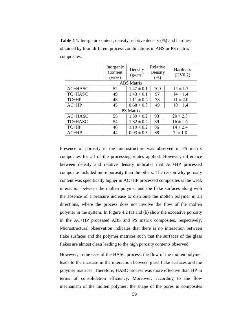
59
Table 4 1. Inorganic content, density, relative density (%) and hardness
obtained by four different process combinations in ABS or PS matrix
composites.
Presence of porosity in the microstructure was observed in PS matrix
composites for all of the processing routes applied. However, difference
between density and relative density indicates that AC+HP processed
composite included more porosity than the others. The reason why porosity
content was specifically higher in AC+HP processed composites is the weak
interaction between the molten polymer and the flake surfaces along with
the absence of a pressure increase to distribute the molten polymer in all
directions, where the process does not involve the flow of the molten
polymer in the system. In Figure 4.2 (a) and (b) show the excessive porosity
in the AC+HP processed ABS and PS matrix composites, respectively.
Microstructural observation indicates that there is no interaction between
flake surfaces and the polymer matrices such that the surfaces of the glass
flakes are almost clean leading to the high porosity contents observed.
However, in the case of the HASC process, the flow of the molten polymer
leads to the increase in the interaction between glass flake surfaces and the
polymer matrices. Therefore, HASC process was more effective than HP in
terms of consolidation efficiency. Moreover, according to the flow
mechanism of the molten polymer, the shape of the pores in composites
Inorganic
Content
(wt%)
Density
(g/cm3)
Relative
Density
(%)
Hardness
(HV0.2)
ABS Matrix
AC+HASC 52 1.47 ± 0.1 100 15 ± 1.7
TC+HASC 49 1.43 ± 0.1 97 14 ± 1.4
TC+HP 48 1.11 ± 0.2 78 11 ± 2.0
AC+HP 45 0.68 ± 0.3 49 10 ± 1.4
PS Matrix
AC+HASC 55 1.39 ± 0.2 93 20 ± 2.3
TC+HASC 54 1.32 ± 0.2 89 16 ± 1.6
TC+HP 46 1.19 ± 0.2 86 14 ± 2.4
AC+HP 44 0.93 ± 0.3 68 7 ± 1.8

60
consolidated by HASC or HP process is different. In the AC+HP processed
composites the pores elongated entrapped in between individual flakes
(shown by arrows in Figure 4.2), while they are in spherical form in the case
of TC+HASC or AC+HASC processed composites (Figure 4.3) due to the
friction building up on the molten polymer during its flow. Since the fluidity
of ABS is higher compared to that of the PS, relative densities of the ABS
matrix composites were superior to those of the PS matrix ones especially in
the case of the HASC including routes.
Figure 4.2. Scanning electron microscope images of the a) ABS matrix and
b) PS matrix composites fabricated by AC+HP process where the pores are
shown by arrows.
Even though the HASC including process combinations involve the flow of
the molten polymer in the system, there still exist porosities in the resulting
composites. Especially in the case of TC+HASC processed composites,
relatively higher amount of porosity points out to the negative effect of the
higher amount of air gaps present in between the initial tapes to be
consolidated as well as the non-Newtonian flow behavior of the molten
polymer. In Figure 4.3 (a) spherical pores present in TC+HASC processed

61
composites can be seen. Moreover, better interaction between the glass flake
surfaces and the polymer matrix in the case of the HASC including routes
compared to HP process including combinations are evident by the polymer
layers adhered on the glass flake surfaces shown by arrows in Figure 4.3 (b).
Figure 4.3. Scanning electron microscope images of composites fabricated
by TC+HASC route (a) presence of spherical pores, (b) adhesion of the
polymer matrix on the glass flake surfaces.
To consolidate the material and to obtain bulk a composite with brick and
mortar architecture, heat was applied on the initially film or tape formed
structures that were schematically illustrated in Figure 4.4. According to the
procedure that was described in Chapter 3, temperature has been increased
during both HASC and HP processes. While increasing temperature, organic
component in the structure started to melt in both cases where it also started
to flow during HASC process following melting. Polymer started to melt in
the regions closer to the die wall, since first the wall of the steel die reached
the adjusted temperature then the center of the structure could reach the
same temperature. Therefore, flow of the molten polymer started from the
(a) (b)

62
regions near the steel die wall and proceeded to the inner parts of the
structure where it started to flow on the glass flake surfaces.
During the flow of the molten polymer, different friction mechanisms
became operative where friction was acting on the molten polymer by both
the glass flake surfaces and the wall of the steel die, which was the primary
drawback to remove the excess organic matrix from the structure during
HASC process. However, although increasing pressure during the HASC
process was enforcing the friction, it was helpful to remove the excess liquid
polymer matrix, and hence to increase the inorganic content of the
composite. During this action, a significant amount of glass flakes was also
lost with the flowing liquid polymer. Nevertheless, the amount of drained
polymer during HASC process was different depending on whether the
initial dried material was formed by AC or TC process. In the case of the
dried initial tapes formed by TC process amount of the drained polymer was
lower, since the scraping action during tape casting leaves lower amount of
polymer in the tapes compared to the films formed by AC process (Figure
4.4).
In AC+HASC process, the flow mechanism of the molten polymer was
different than that of the TC+HASC combination. In Figure 4.4 (b), the
structure of the as-cast initial film is schematically illustrated. According to
this following the AC process there was a random flake orientation and a
relatively higher initial polymer amount in the film to be consolidated. In
this relatively loose and randomly oriented body heat and pressure induced
liquid polymer flow was more effective in removing the excess organic
matrix leading to higher inorganic content, while it was also more efficient
in forming the brick and mortar architecture due to the better flow of the
polymer achieved in the structure. In the case of the TC formed initial
material to be consolidated, the body confined in the steel die contains
relatively lower amount of the organic phase with highly aligned inorganic
phase. This is to say that in this structure there is a thin layer of polymer
available between the glass flakes, and a relatively high interfacial area
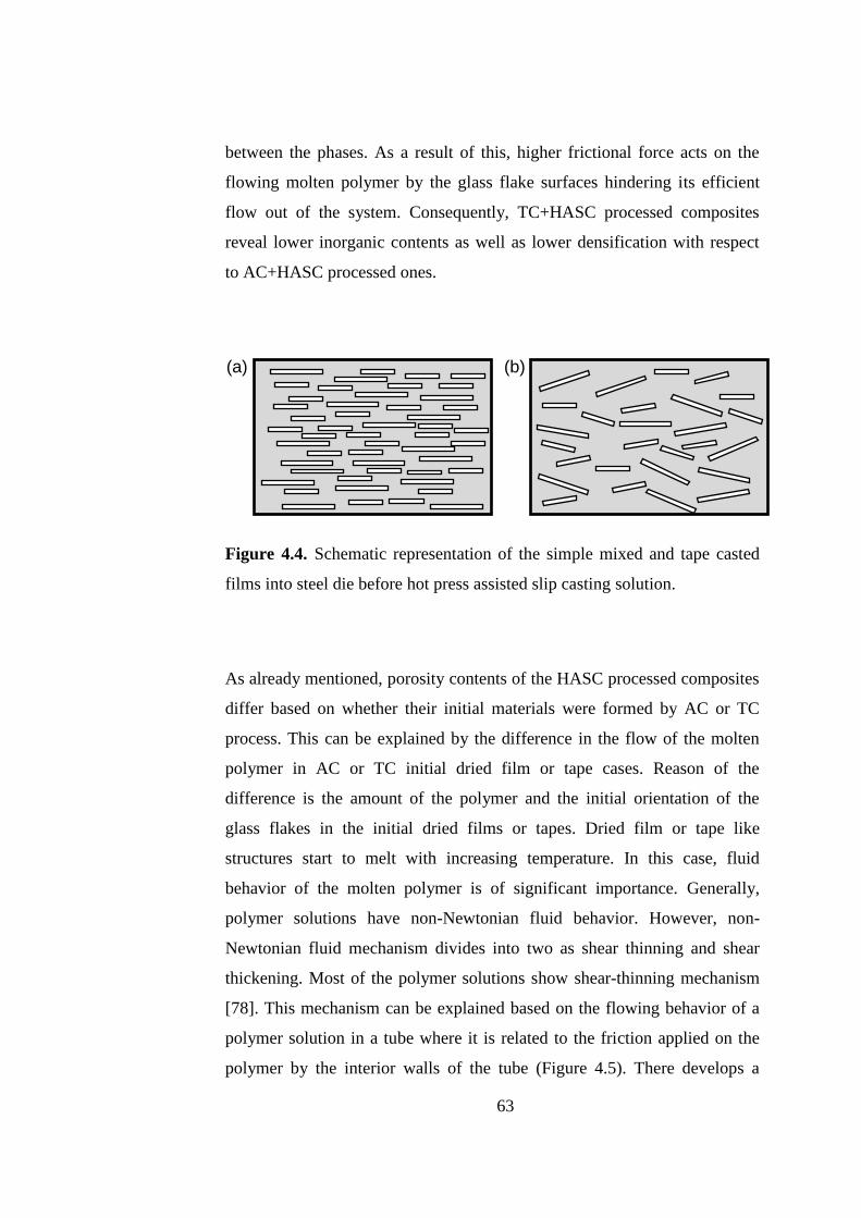
63
between the phases. As a result of this, higher frictional force acts on the
flowing molten polymer by the glass flake surfaces hindering its efficient
flow out of the system. Consequently, TC+HASC processed composites
reveal lower inorganic contents as well as lower densification with respect
to AC+HASC processed ones.
Figure 4.4. Schematic representation of the simple mixed and tape casted
films into steel die before hot press assisted slip casting solution.
As already mentioned, porosity contents of the HASC processed composites
differ based on whether their initial materials were formed by AC or TC
process. This can be explained by the difference in the flow of the molten
polymer in AC or TC initial dried film or tape cases. Reason of the
difference is the amount of the polymer and the initial orientation of the
glass flakes in the initial dried films or tapes. Dried film or tape like
structures start to melt with increasing temperature. In this case, fluid
behavior of the molten polymer is of significant importance. Generally,
polymer solutions have non-Newtonian fluid behavior. However, non-
Newtonian fluid mechanism divides into two as shear thinning and shear
thickening. Most of the polymer solutions show shear-thinning mechanism
[78]. This mechanism can be explained based on the flowing behavior of a
polymer solution in a tube where it is related to the friction applied on the
polymer by the interior walls of the tube (Figure 4.5). There develops a
(a) (b)

64
pressure difference between the interior and exterior (PA>PB) of the polymer
solution affecting its fluidity, and the friction applied by the contact surfaces
controls flow front of the polymer.
In this study, motion of the molten polymer between the glass flakes is
similar to the previously described mechanism on shear thinning. Local
differences in the amount of polymer in the initial AC or TC formed dried
films or tapes leads to the development of pressure and friction variations on
the flowing polymer upon melting. In terms of the fluid mechanism, flow of
the molten polymer in AC+HASC processed composite is easier due to
higher local pressure differences along with lower friction applied on the
polymer by the glass flake surface. In the case of the TC+HASC processed
composites this situation is just the opposite where the previously mention
lower amount of initial polymer with larger interfacial area results in lower
local pressure differences and higher frictional forces, respectively.
Figure 4.5. Flowing of polymer solution like plug between flakes [78].
Additionally, the flow mechanism of polymer includes restitution pointing
out to the withdrawal of the flow front (material line) of the molten polymer
upon the balance of the interior and exterior pressures. Following restitution
curved and stationary polymer front leads to the formation of spherical
pores. The schematic representation of restitution in a viscoelastic fluid is
demonstrated in Figure 4.6. Both AC+HASC and TC+HASC process
combinations resulted in the formation of spherical porosity the amount of
which is higher in the case of TC+HASC processed composites due to

65
higher frictional forces involved that was evidenced by the microstructural
observations.
Figure 4.6. Restitution in a viscoelastic fluid [78].
All these factors could be taken into consideration as they have significant
effects on the alignment of the glass flakes in the composites, and hence
achievement of the desired brick and mortar architecture. Microstructural
examination of the composites fabricated by the four different process
combinations has been conducted on their fracture surfaces obtained after
three point bending tests. Figures 4.7 and 4.8 show the SEM images of the
fracture surfaces of PS and ABS matrix composites respectively fabricated
by each process combination. The images clearly illustrate that especially
HASC process provided the alignment of the glass flakes by means of
simultaneous heat and pressure application which involves the flow of the

66
molten polymer during the process. The HASC processed composites reveal
considerable interaction between the polymer matrix and the glass flake
surfaces with uniform distribution of the polymer in the structure. The brick
and mortar architecture was achieved especially by the HASC method rather
than HP. Independent of the consolidation process applied usage of initial
tapes formed by TC process supplied remarkable nacre-like alignment, as
doctor blading action on the glass flake containing suspension provides
alignment of the flakes even before the consolidation step.
Figure 4.7. Scanning electron microscope images of the fracture surfaces of
the three point bending tested PS matrix composites fabricated by (a)
AC+HASC, (b) TC+HASC, (c) TC+HP and (d) AC+HP.
(a) (b)
(c) (d)

67
Figure 4.8. Scanning electron microscope images of the fracture surfaces of
the three point bending tested ABS matrix composites fabricated by (a)
AC+HASC, (b) TC+HASC, (c) TC+HP and (d) AC+HP.
Three point bending test was conducted in all specimens to determine the
mechanical behavior of the composites. The results showed that AC+HASC
processed composites were superior to the others in terms of flexural
strength. The reason why the AC+HASC processed composites has
demonstrated superior mechanical characteristics to the others can be
explained by the microstructure formation controlled by the flow
mechanism of the molten polymer during HASC process.
(a) (b)
(c) (d)

68
Three point bending test results revealed that independent of the matrix type
HASC processed composites have higher flexural strengths (Figures 4.9 and
4.10) than the HP processed ones mainly due to their lower porosity and
higher inorganic content (Table 1). This effect is more pronounced in the
case of AC+HASC processed composite compared to the TC+HASC
processed one. For PS matrix composites, flexural strength of AC+HASC
processed composites is 21% higher than that of the TC+HASC processed
one also due to relatively more efficient alignment of glass flakes as brick
and mortar architecture based on the presence of fluid flow during HASC
process. For ABS, the increase of the flexural strength was 5%.
On the other hand, AC+HASC processed PS matrix composites revealed
31% higher flexural strength compared to ABS matrix composites
fabricated by the same method, since strength to weight ratio of PS is 59-72
kN-m/kg while that of ABS is 37kN-m/kg. Consequently, PS matrix
composites have higher flexural strength than ABS matrix ones.
Furthermore, PS matrix composites have higher elastic modulus values
compared to ABS matrix ones because of the lower elasticity of the pristine
PS compared to ABS which also reveals itself by the lower flexural strains
achieved in PS matrix composites independent of the processing
combination applied. Three point bending test results presented in Figure
4.9 and 4.10 show the effectiveness of AC+HASC process combination
leading to higher strength composites independent of their thermoplastic
polymer matrix mainly due to the microstructural characteristics it
generates.

69
0 1 2 3 4 5 6 7 80
2
4
6
8
10
12
14
16
18
20
22
3
2
1
Fle
xura
l Str
ess
(M
Pa)
Flexural Strain (%)
1 PS / AC + HASC
2 PS / TC + HASC
3 PS / TC + HP
4 PS / AC + HP
4
Figure 4.9. Flexural stress vs. strain curves of PS matrix composites
fabricated by the four process combinations.
0 1 2 3 4 5 6 7 80
2
4
6
8
10
12
14
16
18
20
22
3
2
1
Fle
xura
l Str
ess
(M
Pa)
Flexural Strain (%)
1 ABS / AC + HASC
2 ABS / TC + HASC
3 ABS / TC + HP
4 ABS / AC + HP
4
Figure 4.10. Flexural stress vs. strain curves of ABS matrix composites
fabricated by the four process combinations.

70
Three point bending test results indicated that composites with different
thermoplastic polymer matrices revealed different mechanical behavior.
Two different thermoplastic polymers namely PS and ABS have different
number average molecular weight as well as different chemical components
and different structural type. All these differences in their inherent
characteristics lead to the difference in the mechanical properties of the
composites they form. PS granules used in this study have 64946 g/mole
number average molecular weight while ABS granules have 28309 g/mole.
According to the number average molecular weights the rheology and
swelling behavior of polymers are different. Higher number average
molecular weight leads to weaker fading response, and hence higher
viscosity of the molten polymer. Moreover, the intrinsic viscosities of PS
and ABS used in this study were 0.585324 dL/g and 0.406511 dL/g,
respectively. This leads to better flow characteristic to ABS during HASC
process. Nevertheless, even though packing and inorganic flake alignment
during the HASC process might be more efficient in the case of ABS
matrix, due to its chemical structure dependent deficient inherent
mechanical strength, AC+HASC processed ABS matrix composites reveal
lower flexural strength compared to PS matrix one.

71
0 1 2 3 4 50
2
4
6
8
10
12
14
16
18
20
22
Fle
xu
ral S
tre
ss (
MP
a)
Flexural Strain %
1 PS / AC + HASC
2 ABS / AC + HASC1
2
Figure 4.11. Variation in mechanical properties of acrylonitrile butadiene
styrene and polystyrene polymer matrices composites fabricated by
AC+HASC method.
To improve the interaction between inorganic and organic phases and to
investigate the coupling agent effect in the resulting mechanical properties
of the composites, glass flake surfaces were treated with
aminopropyltriethoxy type organofunctional silane. As it has been
mentioned earlier on, silane molecule functions as a chemical bridge
bonding to both the inorganic surface and the organic matrix. In the present
case there is a weak interaction between the selected silane and both of the
thermoplastic polymer used. However, despite this weak interaction silane
results in enhanced crosslinking in the polymers [79]. Due to its direct effect
on the polymer and bonding to the inorganics surface, silane treatment is
expected to improve the mechanical characteristics of the targeted
composites.
Silane treated and as-received glass flake surfaces were examined by XPS to
observe the attachment of the silane molecules on the inorganic surfaces. In

72
Figure 4.12 (a) surface chemical composition of as-received glass flakes is
given. Peaks at 102, 153, 284-293, 540 and 1071 eV correspond to Si2p,
Si2s, C1s, O1s, Na1s, respectively, where peaks at 496, 978 and 999 eV
correspond to NaKL1, OKL1 and OKL2 Auger peaks (Figure 4.12 (a)).
Peaks at 102, 285, 400 and 532 eV in Figure 4.12 (b) correspond to Si2p,
C1s, N1s and O1s, respectively. Presence of N1s peak in the case of the
silane treated glass flakes proves the silane attachment to the surface by the
applied procedure. The intensity difference in C1s and Si2p peaks in both
cases points out to the difference in the chemical bonding and the interaction
between the inorganic surface and the silane molecule resulting from the
applied surface functionalization.

73
Figure 4.12. XPS spectra of (a) as-received and (b) silane treated glass flakes.

74
Silane treatment could improve the interaction between the glass flakes
surfaces and the organic matrix. However, modification of the glass flake
surfaces with aminopropyltriethoxy silane results in differences in the
microstructure and chemical structures of the resulting composites.
According to the inorganic content and hardness results given in Table 4.2,
surface treatment by silane is more effective in PS matrix composites
compared to ABS matrix ones due to the interaction difference between the
thermoplastic polymer type and the silane used. Modification with silane in
PS matrix enhances the interlocking in between the polymer chains leading
to enhanced hardness.
Superior molecular attraction between the silane and polystyrene molecules
leads to enhanced interaction between the silane attached glass flake and the
PS matrix. Therefore, as shown in Table 4.2 there is a remarkable inorganic
content difference in PS matrix composites before and after silanization
while there is no change in ABS matrix ones. This corresponds to higher
interlocking of the PS polymer chains resulting in stronger bonding among
the glass flakes leading to higher hardness despite the decrease in the
inorganic content. Even though the inorganic content remains unchanged,
the increase in hardness in the ABS matrix composites after silanization
depends also on the interlocking within the polymer chains despite the
molecular interaction between the silane and ABS molecules are weaker
compared to that in PS matrix. In addition to these, difference in the HASC
process temperatures for PS and ABS matrix composites may also be
effective in the resulting properties, as molecular attraction and bonding
ability of silane to inorganic surfaces changes with temperature as well as
viscosity of the surrounding molten polymer.

75
Table 4.2. Inorganic content, density, relative density (%) and hardness of
AC+HASC processed ABS or PS matrix composites reinforced by as-
received or silane treated glass flakes.
In Figures 4.13 and 4.14 microstructures of AC+HASC processed PS matrix
composites reinforced by as-received or silane treated glass flakes are
shown. According to these microstructures alignment of the flakes seems to
have improved with the silane treatment. Silane improves the interlocking of
polymer chains limiting the amount of matrix remaining between the glass
flakes in order to optimize space filling in the structure. Consequently,
organofunctional silane treatment applied on the inorganic flake surfaces has
a positive effect on the formation of the desired brick and mortar
architecture. The polymer matrix amount remaining in between the glass
flakes is indicated by the arrows in Figures 4.13 and 4.14 showing the
presence of a more uniformly distributed, thinner matrix layer on the
surfaces of silane treated glass flakes. This uniform distribution of the matrix
in the structure is based on the molecular interaction between polymer
chains and silane affecting the flowing behavior of the molten polymer.
Superior alignment along with the uniformly distributed matrix among the
reinforcing phase is the key to achieve strengthening and stiffening in the
nacre-like bio-inspired composites.
Inorganic
Content
(wt%)
Density
(g/cm3)
Relative
Density (%)
Hardness
(HV0.2)
ABS Matrix
AC+HASC/Silan
e 52 1.47 ± 0.2 100 20 ± 2.7
AC+HASC 52 1.47 ± 0.1 100 15 ± 1.7
PS Matrix
AC+HASC/Silan
e 51 1.39 ± 0.1 93 25 ± 2.4
AC+HASC 55 1.39 ± 0.2 93 20 ± 2.3
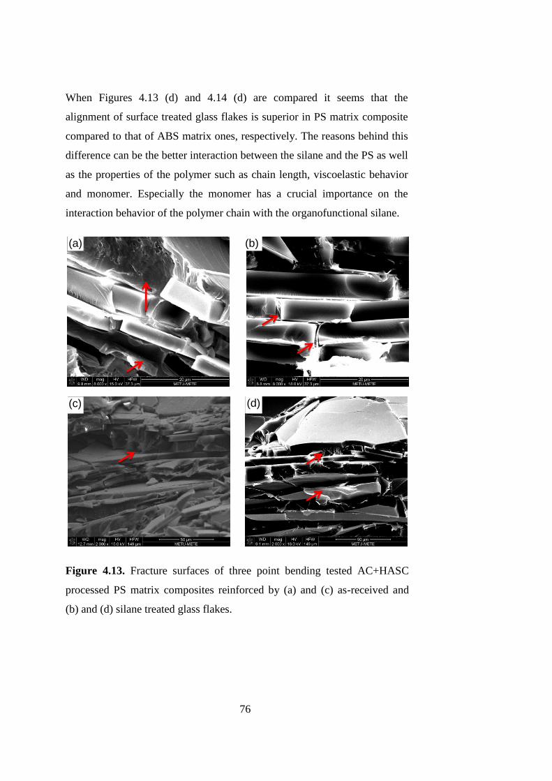
76
When Figures 4.13 (d) and 4.14 (d) are compared it seems that the
alignment of surface treated glass flakes is superior in PS matrix composite
compared to that of ABS matrix ones, respectively. The reasons behind this
difference can be the better interaction between the silane and the PS as well
as the properties of the polymer such as chain length, viscoelastic behavior
and monomer. Especially the monomer has a crucial importance on the
interaction behavior of the polymer chain with the organofunctional silane.
Figure 4.13. Fracture surfaces of three point bending tested AC+HASC
processed PS matrix composites reinforced by (a) and (c) as-received and
(b) and (d) silane treated glass flakes.
(a) (b)
(c) (d)

77
Figure 4.14. Fracture surfaces of three point bending tested AC+HASC
processed ABS matrix composites reinforced by (a) and (c) as-received and
(b) and (d) silane treated glass flakes.
Flexural stress vs strain curves of AC+HASC processed PS and ABS matrix
composites reinforced by as-received and silane treated glass flakes are
shown in Figure 4.15. According to these three point bending test results, it
is clear that after silane treatment there is a remarkable increase in flexural
strength and stiffness for both of the polymer matrices. Results showed that
after silane treatment flexural strengths of PS and ABS matrix composites
increased by 34% and 27%, respectively, compared to their counterparts
reinforced by as-received glass flakes. Higher strength and stiffness of PS
matrix composites compared to those of ABS matrix ones is also evident in
both of the cases.
(a) (b)
(c) (d)

78
0 1 2 3 4 50
5
10
15
20
25
30
4
3
1
F
lexura
l S
tress (
MP
a)
Flexural Strain (%)
1 PS / AC + HASC - SILANE
2 PS / AC + HASC
3 ABS / AC + HASC - SILANE
4 ABS / AC + HASC
2
Figure 4.15. Flexural stress vs. strain curves of AC+HASC processed PS
and ABS matrix composites reinforced by as-received and silane treated
glass flakes.
For both thermoplastic polymer matrices, mechanical response of the fabricated
composites has improved when reinforced by silane treated glass flakes
revealing itself with increasing flexural strength and stiffness values. This is an
expected result of treating inorganic reinforcement surfaces with a proper silane
applied with a proper method. Silane treatment could enhance the possible
interactions between the polymer chains. However, penetration of polymer
chains into the silane structure could be suppressed by the Si-O-Si bonds
between the silane molecules and the inorganic surface [79]. In Figure 4.16, the
schematic representation of the interaction between the polymer chains and
aminopropyltriethoxy silane is illustrated. In this schematic representation,
polymer chains interlock with each other, and there is a small attraction between
the silane molecules and the polymer chains. Although there is no direct
attachment between the silane and polymer molecules, enhanced interlocking of

79
the polymer chains due to the effect of silane can lead to increase in strength of
the composites.
Figure 4.16. Schematic representation of the interaction between
aminoproyltriethoxy silane and polymer chains [79].
Effect of silane treatment on the fracture resistance of the AC+HASC
processed PS and ABS matrix composites has been investigated by work of
fracture tests. Energy absorbed by the material during the growth of a crack
has been determined by dividing the area under the Load vs. Extension
curves (Figure 4.17) to the fracture surface area of the composite after the
test. Although fracture surfaces of composites were tortuous rather than
being flat after the work of fracture tests, the area was taken to be smooth as
a first approximation, which has also been done in studies reporting about
the toughening mechanism of nacre [49].
Results of this test demonstrate the ability to absorb energy during crack
propagation, and hence fracture. According to the results presented in Figure
4.17, energy absorption has increased from 171 J/m2 to 295 J/m
2 in
AC+HASC processed PS matrix composite after silane treatment. In the
case of the AC+HASC processed ABS matrix composite energy absorption
has increased from 349 J/m2 and 379 J/m
2 following the silane treatment. As
expected, ABS matrix composites show much higher work of fracture
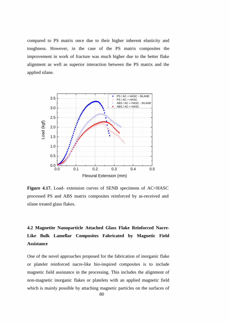
80
compared to PS matrix once due to their higher inherent elasticity and
toughness. However, in the case of the PS matrix composites the
improvement in work of fracture was much higher due to the better flake
alignment as well as superior interaction between the PS matrix and the
applied silane.
0.0 0.1 0.2 0.3 0.4 0.50.0
0.5
1.0
1.5
2.0
2.5
3.0
3.5
Load (
kgf)
Flexural Extension (mm)
PS / AC + HASC - SILANE
PS / AC + HASC
ABS / AC + HASC - SILANE
ABS / AC + HASC
Figure 4.17. Load- extension curves of SENB specimens of AC+HASC
processed PS and ABS matrix composites reinforced by as-received and
silane treated glass flakes.
4.2 Magnetite Nanoparticle Attached Glass Flake Reinforced Nacre-
Like Bulk Lamellar Composites Fabricated by Magnetic Field
Assistance
One of the novel approaches proposed for the fabrication of inorganic flake
or platelet reinforced nacre-like bio-inspired composites is to include
magnetic field assistance in the processing. This includes the alignment of
non-magnetic inorganic flakes or platelets with an applied magnetic field
which is mainly possible by attaching magnetic particles on the surfaces of

81
the reinforcing materials. In this scope, within the current study magnetite
nanoparticle attached glass flake reinforced nacre-like bulk lamellar
composites were fabricated by magnetic field assistance.
Applied procedure comprised of attaching magnetite nanoparticles on as-
received glass flake surfaces, aligning these surface modified flakes by a
magnetic field supplied using a hard magnet and finally consolidating the
dried initial material via hot-pressing to obtain bulk composites. The success
of the attachment of magnetite nanoparticles by the applied treatment has
been proven by the change in the color of the initially transparent glass
flakes to brown which was the color of the used cationic magnetite
nanoparticle solution. In Figure 4.18 coloring of the glass flakes with
magnetite nanoparticle attachment can be observed both before and after
filtration.
Figure 4.18. Color difference between as-received and nanoparticle attached
glass flakes before and after filtering the processing solution.
Optical microscope image of magnetite nanoparticle glass flakes placed on
the hard magnet shows the effect of magnetic field on these surface
modified glass flakes (Figure 4.19). It is clear that surface modified glass
flakes align with the magnetic field being their basal planes perpendicular to
the magnet surface. The alignment of these flakes could also be observed by
naked eye very clearly because of the change in the color of the mass by
alignment. With the alignment of the surface modified glass flakes the color
of the mass changes from light to dark brown where its brightness decreases
at the same time.

82
Figure 4.19 Optical microscope image of the surface modified glass flakes
aligned on the hard magnet.
To investigate the attachment of magnetite nanoparticles in detail surfaces of
as-received and surface modified glass flakes were analyzed by FTIR. As it
can be seen in Figure 4.20, acquired FTIR spectra of the as-received and
magnetite nanoparticle attached glass flakes show different peak positions
and structures caused by the difference in the existing bonds in the two
cases. As glass flakes is mainly composed of SiO2, there are three different
peaks common to both as-received and surface modified glass flakes
corresponding to Si-O-Si bond. Peaks at 860-940, at 710-1175 and 415-540
cm-1
correspond to Si-O-Si bond stretching, tetrahedral Si-O-Si bonding and
Si-O-Si bond bending, respectively. For both of the cases the peaks
observed at 1400 cm-1
might correspond to Al2O3 since the C-type glass
flakes contain low amount of aluminum oxide. Peaks present between 800
to 950 cm-1
in the FTIR spectrum of the magnetite nanoparticles attached
glass flakes (Figure 4.20 (b)) corresponds to Si-O-Fe attachment. In addition

83
with the applied surface modification, FTIR spectrum peaks of the as-
received glass flakes shifted and the area under the peaks changed.
Figure 4.20 FTIR spectra of (a) as-received and (b) magnetite nanoparticle
attached glass flakes.

84
After the alignment of the surface modified glass flakes vertically on the
magnet surface, necessary amount of polymer solution was added drop by
drop on the aligned glass flakes. Three different polymer solution
compositions were used in order to investigate the effect of the amount of
the polymer matrix on the resulting properties of the composites. Initial
amount of the polymer, which is polystyrene (PS) in the current case, was
changed such that the matrix content in the composites before consolidation
were 38, 43 and 53 wt%. At this step the critical issue was not to harm the
flake alignment supplied by the magnetic field, while increasing the organic
matrix content to be added.
After adding different amounts of polymers on the aligned glass flakes for
each set, the consolidation of the mass was achieved following its drying by
hot-pressing. Hot-pressing method includes melting of the polymer matrix
which is under the action of a unidirectional pressure leading to ideally
uniform distribution of the organic matrix in all structure. However,
although the consolidated composite contained sufficient amount of the
polymer matrix, absence of polymer flow, and hence drainage, from the
system has led to porosity formation. In Table 4.3, percent relative density
for different initial polymer amounts in the composites is shown. According
to these results, increase of the initial polymer content resulted in denser
composites, i.e. lower amount of residual porosity, since molten polymer
can fill in the available gaps in the structure more efficiently and uniformly
with increasing amount of liquid polymer in the structure. Microhardness
results demonstrated no considerable difference for varying polymer
contents. Even though there is 10% densification difference between the
maximum and minimum achieved densities, presence of similar hardness
values can be attributed to the locality of the microhardness test applied and
the relatively larger pore sizes observed.

85
Table 4.3. Density, relative density (%) and hardness of the fabricated
composites for three different initial polymer contents (wt% PS).
Alignment of the magnetite nanoparticle attached glass flakes by means of
magnetic field application was followed by the HP process as the
consolidation process which was mentioned in Chapter 3 in detail.
Consequently, microstructure formation in magnetically aligned and hot-
pressed composites can be compared to those achieved by the previously
discussed process combinations including HP process, namely TC+HP and
AC+HP. In this scope, microstructural observation of the composites
containing various amounts of polymer matrices revealed that brick and
mortar arrangement was achieved in all composites independent of the
polymer content (Figure 4.21). Similar nacre-like microstructure has also
been achieved by the previously presented PS matrix composites fabricated
by HP process containing combinations (Figure 4.7 (c) and (d)).
Polymer
Content
(wt% PS)
Density
(g/cm3)
Relative
Density (%)
Hardness
(HV0.2)
53 1.31 100 16 ± 3.1
43 1.23 90 15 ± 3.1
38 1.21 89 15 ± 3.0

86
Figure 4.21 Fracture surfaces of the three point bending tested composites
fabricated by magnetic field assistance and HP containing (a) 38 wt %, (b)
43 wt % and (c) 53 wt % PS matrix.
To reveal the mechanical properties of composites fabricated by magnetic
field assistance method, three point bending test was conducted. Three point
bending test results revealed the increase in the flexural strength of the
composites with increasing polymer matrix content. The proportionality
between the strength and the polymer matrix content can be attributed to the
improvement of the interaction between the matrix and the magnetite
nanoparticle attached flakes with the help of the efficient distribution of the
matrix in the structure. According to the three point bending test results
shown in Figure 4.22, composite containing of 53 wt% polymer matrix has
35% and 163% higher flexural strength than the composites containing 43
and 38 wt% polymer matrix, respectively. Expectedly, 38 wt% polymer
matrix containing composite, which corresponds to the highest amount of
(a) (b)
(c)

87
the inorganic phase content, has the highest stiffness, yet both of its flexural
stress and failure to strain are the lowest due to the inefficient stress transfer
from the matrix to the reinforcement caused by its non-uniform distribution.
0 1 2 3 40
2
4
6
8
10
12
14
16
F
lexura
l S
tress (
MP
a)
Flexural Strain (%)
53 wt % PS
43 wt % PS
38 wt % PS
Figure 4.22. Three point bending test data of composites fabricated by
magnetic field assistance followed by HP having different amounts of
polymer matrix.
The interaction between the PS matrix and the magnetite nanoparticles
attached on the glass flake surfaces also have a crucial effect on the resulting
mechanical properties in addition to the effect of polymer content and
distribution within the composites. The interaction between the PS
molecules and the magnetite particles has been schematically illustrated in
Figure 4.2, where the magnetite nanoparticles act as an adhesive strongly
bonding the organic and inorganic phases. Increasing polymer content
resulting in a more uniform distribution in the composites corresponds to
higher effectiveness in the interaction between the PS molecules and
magnetite nanoparticle attached glass flake surfaces.
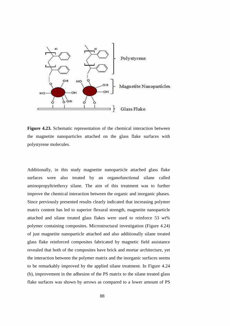
88
Figure 4.23. Schematic representation of the chemical interaction between
the magnetite nanoparticles attached on the glass flake surfaces with
polystyrene molecules.
Additionally, in this study magnetite nanoparticle attached glass flake
surfaces were also treated by an organofunctional silane called
aminopropyltriethoxy silane. The aim of this treatment was to further
improve the chemical interaction between the organic and inorganic phases.
Since previously presented results clearly indicated that increasing polymer
matrix content has led to superior flexural strength, magnetite nanoparticle
attached and silane treated glass flakes were used to reinforce 53 wt%
polymer containing composites. Microstructural investigation (Figure 4.24)
of just magnetite nanoparticle attached and also additionally silane treated
glass flake reinforced composites fabricated by magnetic field assistance
revealed that both of the composites have brick and mortar architecture, yet
the interaction between the polymer matrix and the inorganic surfaces seems
to be remarkably improved by the applied silane treatment. In Figure 4.24
(b), improvement in the adhesion of the PS matrix to the silane treated glass
flake surfaces was shown by arrows as compared to a lower amount of PS
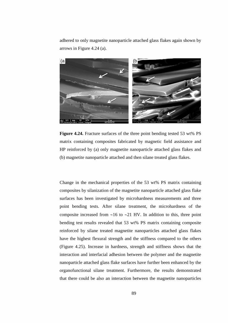
89
adhered to only magnetite nanoparticle attached glass flakes again shown by
arrows in Figure 4.24 (a).
Figure 4.24. Fracture surfaces of the three point bending tested 53 wt% PS
matrix containing composites fabricated by magnetic field assistance and
HP reinforced by (a) only magnetite nanoparticle attached glass flakes and
(b) magnetite nanoparticle attached and then silane treated glass flakes.
Change in the mechanical properties of the 53 wt% PS matrix containing
composites by silanization of the magnetite nanoparticle attached glass flake
surfaces has been investigated by microhardness measurements and three
point bending tests. After silane treatment, the microhardness of the
composite increased from 16 to 21 HV. In addition to this, three point
bending test results revealed that 53 wt% PS matrix containing composite
reinforced by silane treated magnetite nanoparticles attached glass flakes
have the highest flexural strength and the stiffness compared to the others
(Figure 4.25). Increase in hardness, strength and stiffness shows that the
interaction and interfacial adhesion between the polymer and the magnetite
nanoparticle attached glass flake surfaces have further been enhanced by the
organofunctional silane treatment. Furthermore, the results demonstrated
that there could be also an interaction between the magnetite nanoparticles
(a)
(b)

90
and silane molecules contribution to the improvement in the mechanical
characteristics.
0.0 0.5 1.0 1.5 2.0 2.5 3.0 3.5 4.00
2
4
6
8
10
12
14
16
18
Fle
xu
ral S
tre
ss (
MP
a)
Flexural Strain (%)
53 wt % PS / silane treated
53 wt % PS
43 wt % PS
38 wt % PS
Figure 4.25. Three point bending test data of composites fabricated by
magnetic field assistance followed by HP having different amounts of
polymer matrix also including the silane treated one.
Fracture resistance of the composites fabricated by magnetic field assistance
followed by HP has been investigated via work of fracture tests applied on
all composites. As mentioned previously, energy absorbed by the material
during the growth of a crack has been determined by dividing the area under
the Load vs. Extension curves (Figure 4.26) to the fracture surface area of
the composite after the test. Although fracture surfaces of the composites
were not smooth rather than being flat after the work of fracture tests, the
area was taken to be smooth and flat as a first approximation, which has also
been done in studies reporting about the toughening mechanism of nacre

91
[49]. According to the results presented in Figure 4.26, energy absorption
has increased from 181 J/m2 to 314 J/m
2 for 53 wt% PS matrix containing
composites after treating the magnetite nanoparticle attached glass flakes
with silane. Energy absorption has increased from 156 J/m2 to 175 J/m
2 by
increasing the matrix content in the composites from 43 wt% to 38 wt%.
Mechanical test results demonstrated increasing the polymer matrix content
increases both the strength and fracture resistance of the composites
fabricated by magnetic field assistance followed by HP which were further
enhanced by the application of silane treatment on the magnetite
nanoparticle attached glass flakes. This demonstrates that both strengthening
and toughening can be achieved in nacre-like bulk lamellar composites by
the proper alignment of the inorganic flakes in the matrix, the usage of the
optimum amount of organic-inorganic phase ratio along with the application
of an organofunctional silane treatment on the inorganic surfaces.
0.0 0.2 0.4 0.6 0.80
1
2
3
4
Lo
ad
(kg
f)
Extension (mm)
53 wt % PS / Silane treated
53 wt % PS
43 wt % PS
38 wt % PS
Figure 4.26. Load vs. extension curves of WOF tested composites
fabricated by magnetic field assistance followed by HP process having
different amounts of polymer matrix also including the silane treated one.

92

93
CHAPTER 5
CONCLUSION
In this study, hot-pressing and magnetic field assistance based processing
method combinations have been developed in order to fabricate nacre-like
bulk lamellar thermoplastic matrix composites reinforced by glass flakes.
For both of the processing routes, glass flake surfaces were treated with an
organofunctional silane, in order to tailor the interface between the organic
and inorganic phases and to achieved strengthening along with improvement
in fracture resistance. Following the fabrication steps mechanical properties
of the fabricated composites were examined using three point bending,
micro hardness and work of fracture tests.
Within the scope of the hot-pressing based methods, four different
combinations composed of as-casting (AC) or tape casting (TC) as initial
shaping processes followed by hot-pressing (HP) or hot press assisted slip
casting (HASC) as consolidation steps were studied. These four
combinations were designated as AC +HASC, TC+HASC, AC+HP and
TC+HP. Effectiveness of these process combinations in revealing brick and
mortar structure similar to that of nacre with enhanced mechanical
characteristics has been investigated. According to the findings previously
presented in detail, even though all of the four process combinations have
led to the nacre-like brick and mortar architecture, this structure could be
achieved most properly using AC+HASC where the inorganic content and
densification could be maximized.

94
To control the alignment of the inorganic flakes in reaching to the nacre-like
microstructure similar to that of the mollusc shell, magnetic field assistance
technique was examined as a novel approach. The interaction with the
applied magnetic field was supplied by the attachment of magnetite
nanoparticles on non-magnetic glass flake surfaces. The main point in this
part was to change the organic to inorganic ratio in the composite and to
control the interfacial properties between the two constituent phases.
Desired brick and mortar microstructural architecture was obtained by
magnetic field alignment followed by hot-pressing for changing organic
contents of the composites.
Following points demonstrate the major conclusions drawn at the end of this
study:
Among the hot-pressing based process combinations AC+HASC is
more effective in obtaining mechanically superior nacre-like bulk
composites with the optimum inorganic content and polymer matrix
distribution it provide in the structure.
Of the two different thermoplastic matrices, PS and ABS, used in the
composites fabricated by hot-pressing based process combinations,
PS leads to higher mechanical strength and stiffness due to its higher
molecular weight and crystalline structure.
According to the three point bending results PS matrix composite
fabricated by AC+HASC method reveals 21% higher flexural
strength than the one fabricated by TC+HASC method. In the case of
the ABS matrix composites above mentioned difference in the
flexural strength is 32%.
Even though TC+HASC process combination has also led to brick
and mortar architecture with well-oriented glass flakes in the
95
structure, it revealed deficient mechanical properties compared to
AC+HASC mainly caused by the higher porosity content resulting
from the inefficient flow of the molten polymer during HASC step.
Treatment of glass flake surfaces with an organofunctional silane,
namely aminopropyltriethoxy silane, improved the interaction
between the organic and inorganic phases revealing itself with
increased strength values following this surface functionalization.
For the AC+HASC processed PS and ABS matrix composites
flexural strength increased by 34% and 27%, respectively, by the
applied surface functionalization using silane.
Work of fracture test results demonstrated that AC+HASC processed
ABS matrix composites have higher fracture resistance due to higher
elasticity and toughness of the ABS matrix. However, even though
surface functionalization has led to an improvement in the energy
absorption capacity of both matrix composites during crack growth,
enhancement in the case of PS matrix composites was much more
remarkable pointing out to a more effective interfacial characteristic
achieved by silanization.
Magnetite nanoparticles can be attached on glass flake surfaces from
a cationic solution effectively in controlled amounts. Magnetite
nanoparticle attached glass flakes respond to the applied field and
their orientation can be controlled.
In the case of composites fabricated by magnetic field assistance and
hot-pressing, increasing the matrix content in the material has led to
higher strength values, where the matrix can be distributed more
effectively and uniformly in the structure when its amount is higher.
96
This shows that rather than maximizing the inorganic reinforcement
content its ratio with the matrix should be optimized for optimized
mechanical characteristics, and hence for maximized mechanical
performance.
Surface functionalization of magnetite nanoparticle attached glass
flake surfaces has led to 10% increase in flexural strength of
composites fabricated by magnetic field assistance.
The efficiency of the magnetic field assistance in controlling the
alignment of the inorganic flakes depends on the strength of the
applied magnetic field. Despite this limitation this is a practical
method for the fabrication of nacre-like bulk lamellar composites
with thermoplastic as well as thermoset polymer matrices.
The methods mentioned in this dissertation could be applied to
various types of thermoplastic polymer matrices. Furthermore, any
inorganic material with flake or platelet morphology such as alumina
or CaCO3 etc. can be used as reinforcement in such composites using
these methods. Consequently, presented methods are useful and
efficient methods for the fabrication of bio-inspired bulk lamellar
composites which can make them available for structural
engineering applications.
97
REFERENCES
[1]. Munch, E., Launey, M. E., Alsem, D. H., Saiz, E., Tomsia, a P., &
Ritchie, R. O. (2008). Tough, bio-inspired hybrid materials. Science (New
York, N.Y.), 322(5907), 1516–20. doi:10.1126/science.1164865
[2]. Barthelat, F. (2007). Biomimetics for next generation materials.
Philosophical Transactions. Series A, Mathematical, Physical, and
Engineering Sciences, 365(1861), 2907–19. doi:10.1098/rsta.2007.0006
[3]. Xia, F., & Jiang, L. (2008). Bio-Inspired, Smart, Multiscale Interfacial
Materials. Advanced Materials, 20(15), 2842–2858.
doi:10.1002/adma.200800836
[4]. Wegst, U. G. K., & Ashby, M. F. (2004). The mechanical efficiency of
natural materials. Philosophical Magazine, 84(21), 2167–2186.
doi:10.1080/14786430410001680935
[5]. Ashby, M. F., Gibson, L. J., Wegst, U., & Olive, R. (1995). The
Mechanical Properties of Natural Materials. I. Material Property Charts.
Proceedings of the Royal Society A: Mathematical, Physical and
Engineering Sciences, 450(1938), 123–140. doi:10.1098/rspa.1995.0075
[6]. Katti, K. S., & Katti, D. R. (2006). Why is nacre so tough and strong?
Materials Science and Engineering: C, 26(8), 1317–1324.
doi:10.1016/j.msec.2005.08.013
[7]. Katti, K. S., Mohanty, B., & Katti, D. R. (2006). Nanomechanical
properties of nacre, 58105(August 2005). doi:10.1557/JMR.2006.0147
[8]. Tushtev, K., Murck, M., & Grathwohl, G. (2008). On the nature of the
stiffness of nacre. Materials Science and Engineering: C, 28(7), 1164–1172.
doi:10.1016/j.msec.2007.10.039
[9]. Katti, K. S., Katti, D. R., Pradhan, S. M., & Bhosle, A. (2011). Platelet
interlocks are the key to toughness and strength in nacre. Journal of
Materials Research, 20(05), 1097–1100. doi:10.1557/JMR.2005.0171
[10]. Group, B., Zoology, A., & Materials, W. (1990). Comparison of nacre
with other ceramic composites, 25.

98
[11]. Oner Ekiz, O., Dericioglu, A. F., & Kakisawa, H. (2009). An efficient
hybrid conventional method to fabricate nacre-like bulk nano-laminar
composites. Materials Science and Engineering: C, 29(6), 2050–2054.
doi:10.1016/j.msec.2009.04.001
[12]. Gurbuz, S. N., & Dericioglu, A. F. (2013). Effect of reinforcement
surface functionalization on the mechanical properties of nacre-like bulk
lamellar composites processed by a hybrid conventional method. Materials
Science & Engineering. C, Materials for Biological Applications, 33(4),
2011–9. doi:10.1016/j.msec.2013.01.013
[13]. Chen, R., Wang, C., Huang, Y., & Le, H. (2008). An efficient
biomimetic process for fabrication of artificial nacre with ordered-
nanostructure. Materials Science and Engineering: C, 28(2), 218–222.
doi:10.1016/j.msec.2006.12.008Artificial Carbonate Nanocrystals.pdf.
(n.d.).
[14]. Pandit, A., Ocakoglu, K., Buda, F., van Marle, T., Holzwarth, A. R., &
de Groot, H. J. M. (2013). Structure determination of a bio-inspired self-
assembled light-harvesting antenna by solid-state NMR and molecular
modeling. The Journal of Physical Chemistry. B, 117(38), 11292–8.
doi:10.1021/jp402210xBioinspired Au TiO2 photocatalyst derived from
butterfly wing (Papilio Paris).pdf. (n.d.).
[15]. Libanori, R., Erb, R. M., & Studart, A. R. (2013). Mechanics of
platelet-reinforced composites assembled using mechanical and magnetic
stimuli. ACS Applied Materials & Interfaces, 5(21), 10794–805.
doi:10.1021/am402975a
[16]. Luz, G. M., & Mano, J. F. (2009). Biomimetic design of materials and
biomaterials inspired by the structure of nacre. Philosophical Transactions.
Series A, Mathematical, Physical, and Engineering Sciences, 367(1893),
1587–605. doi:10.1098/rsta.2009.0007
[17]. Katti, D. R., Katti, K. S., Sopp, J. M., & Sarikaya, M. (2001). 3D ®
nite element modeling of mechanical response in nacre-based hybrid
nanocomposites, 11.25th Anniversary Article
[18]. Kakisawa, H., & Sumitomo, T. (2011). The toughening mechanism of
nacre and structural materials inspired by nacre. Science and Technology of
Advanced Materials, 12(6), 064710. doi:10.1088/1468-6996/12/6/064710
[19] .Luz, G. M., & Mano, J. F. (2010a). Mineralized structures in nature:
Examples and inspirations for the design of new composite materials and
biomaterials. Composites Science and Technology, 70(13), 1777–1788.
doi:10.1016/j.compscitech.2010.05.013

99
[20]. Tang, Z., Kotov, N. a, Magonov, S., & Ozturk, B. (2003).
Nanostructured artificial nacre. Nature Materials, 2(6), 413–8.
doi:10.1038/nmat906
[21]. Barthelat, F., Li, C., Comi, C., & Espinosa, H. D. (2006). Mechanical
properties of nacre constituents and their impact, 3111(July 2005), 1977–
1986. doi:10.1557/JMR.2006.023
[22]. Mukherjee, A. (Ed.). (2010). Biomimetics Learning from Nature .
InTech.doi:10.5772/198
[23]. Thomas, S., Ninan, N., Mohan, S., & Francis, E. (2012). Natural
Polymers, Biopolymers, Biomaterials, and Their Composites, Blends, and
IPNs (Vol. 2). Apple Academic Press
[24]. DeMouthe J.F. (Ed.) Elsevier.(2006). Natural Materials Sources,
Properties and Uses.
[25]. Jiang, L.,Feng L.(2010). BIOINSPIRED INTELLIGENT
NANOSTRUCTURED INTERFACIAL MATERIALS. Chemical Industry
Press.
[26]. Mohanty, A. K., Drzal, L. T., & Group, F. (2005). NATURAL FIBERS
, BIOPOLYMERS , AND BIOCOMPOSITES.
[27]. Baker, A., Dutton, S., & Kelly, D. (2004). Composite Materials for
Aircraft Structures . American Institute of Aeronautics and Astronautics.
[28]. Chung, D.L.D.(2010).Composite Materials Second Edition. Springer.
doi:10.1007/978-1-84882-831-5
[29]. Wallenberger,F.T.,Bingham,P.A.(2010). Fiberglass and Glass
Technology Energy Friendly Compositions and Applications
.Springer.doi:10.1007/978-1-4419-0736-3
[30]. Thomas, S., Joseph, K., Malhotra, S. K., & Goda, K. (n.d.). Edited by
Related Titles Nanocomposites Wood-Plastic Composites Rubber
Nanocomposites Flame Retardant Polymer Nanocomposites Polyolefin
Blends and Composites Advances in Bioceramics and Biocomposites II ,
Ceramic Engineering and Science Polyolefin Composi.
[31]. Liu, K., & Jiang, L. (2011). Bio-inspired design of multiscale
structures for function integration. Nano Today, 6(2), 155–175.
doi:10.1016/j.nantod.2011.02.002

100
[32]. Lee, Y., Chung, H. J., Yeo, S., Ahn, C.-H., Lee, H., Messersmith, P.
B., & Park, T. G. (2010). Thermo-sensitive, injectable, and tissue adhesive
sol–gel transition hyaluronic acid/pluronic composite hydrogels prepared
from bio-inspired catechol-thiol reaction. Soft Matter, 6(5), 977.
doi:10.1039/b919944f
[33]. Tampieri, A., Celotti, G., Landi, E., Sandri, M., Roveri, N., & Falini,
G. (2003). Biologically inspired synthesis of bone-like composite: self-
assembled collagen fibers/hydroxyapatite nanocrystals. Journal of
Biomedical Materials Research. Part A, 67(2), 618–25.
doi:10.1002/jbm.a.10039
[34]. Porter, B. M. M., & Mckittrick, J. (n.d.). It’s tough to be strong :
Advances in bioinspired based materials, 93(5).
[35]. Haldar, S., & Bruck, H. a. (2014). Mechanics of composite sandwich
structures with bioinspired core. Composites Science and Technology, 95,
67–74. doi:10.1016/j.compscitech.2014.02.011
[36]. Ji, B., & Gao, H. (2004). Mechanical properties of nanostructure of
biological materials. Journal of the Mechanics and Physics of Solids, 52(9),
1963–1990. doi:10.1016/j.jmps.2004.03.006
[37]. Liu, K., Yao, X., & Jiang, L. (2010). Recent developments in bio-
inspired special wettability. Chemical Society Reviews, 39(8), 3240–55.
doi:10.1039/b917112f
[38]. Yao, H.-B., Tan, Z.-H., Fang, H.-Y., & Yu, S.-H. (2010). Artificial
nacre-like bionanocomposite films from the self-assembly of chitosan-
montmorillonite hybrid building blocks. Angewandte Chemie (International
Ed. in English), 49(52), 10127–31. doi:10.1002/anie.201004748
[39]. Feng, X.-Q., Gao, X., Wu, Z., Jiang, L., & Zheng, Q.-S. (2007).
Superior water repellency of water strider legs with hierarchical structures:
experiments and analysis. Langmuir : The ACS Journal of Surfaces and
Colloids, 23(9), 4892–6. doi:10.1021/la063039b
[40]. Chen, J., Su, H., Song, F., & Moon, W. (2012). Bio inspired Au/TiO2
photocatalyst derived from butterfly wing (Papilio Paris). Journal of Colloid
and Interface Science RetrievedSeptember 15, 2014 from
http://www.sciencedirect.com/science/article/pii/S002197971101544X
[41]. Meyers, M. A., Lin, A. Y.-M., Chen, P.-Y., & Muyco, J. (2008).
Mechanical strength of abalone nacre: role of the soft organic layer. Journal
of the Mechanical Behavior of Biomedical Materials, 1(1), 76–85.
doi:10.1016/j.jmbbm.2007.03.001

101
[42]. Barthelat, F., Tang, H., Zavattieri, P., Li, C., & Espinosa, H. (2007).
On the mechanics of mother-of-pearl: A key feature in the material
hierarchical structure. Journal of the Mechanics and Physics of Solids,
55(2), 306–337. doi:10.1016/j.jmps.2006.07.007
[43]. Currey, J. D. (1977). Mechanical Properties of Mother of Pearl in
Tension. Proceedings of the Royal Society B: Biological Sciences,
196(1125), 443–463. doi:10.1098/rspb.1977.0050
[44]. Luz, G. M., & Mano, J. F. (2010b). Mineralized structures in nature:
Examples and inspirations for the design of new composite materials and
biomaterials. Composites Science and Technology, 70(13), 1777–1788.
doi:10.1016/j.compscitech.2010.05.013
[45]. Stempflé, P., Pantalé, O., Rousseau, M., Lopez, E., & Bourrat, X.
(2010). Mechanical properties of the elemental nanocomponents of nacre
structure. Materials Science and Engineering: C, 30(5), 715–721.
doi:10.1016/j.msec.2010.03.003
[46]. Rousseau, M., Lopez, E., Couté, A., Mascarel, G., Smith, D. C.,
Naslain, R., & Bourrat, X. (2005). Sheet nacre growth mechanism: a
Voronoi model. Journal of Structural Biology, 149(2), 149–57.
doi:10.1016/j.jsb.2004.09.005
[47]. Espinosa, H. D., Rim, J. E., Barthelat, F., & Buehler, M. J. (2009).
Merger of structure and material in nacre and bone – Perspectives on de
novo biomimetic materials. Progress in Materials Science, 54(8), 1059–
1100. doi:10.1016/j.pmatsci.2009.05.001
[48]. Lin, A., & Meyers, M. A. (2005). Growth and structure in abalone
shell. Materials Science and Engineering: A, 390(1-2), 27–41.
doi:10.1016/j.msea.2004.06.072
[49]. Jackson, A. P., Vincent, J. F. V., & Turner, R. M. (1988). The
Mechanical Design of Nacre. Proceedings of the Royal Society B:
Biological Sciences, 234(1277), 415–440. doi:10.1098/rspb.1988.0056
[50]. Meyers, M. A., Chen, P.-Y., Lin, A. Y.-M., & Seki, Y. (2008).
Biological materials: Structure and mechanical properties. Progress in
Materials Science, 53(1), 1–206. doi:10.1016/j.pmatsci.2007.05.002
[51]. Chen, P.-Y., McKittrick, J., & Meyers, M. A. (2012). Biological
materials: Functional adaptations and bioinspired designs. Progress in
Materials Science, 57(8), 1492–1704. doi:10.1016/j.pmatsci.2012.03.001

102
[52]. Cartwright, J. H. E., & Checa, A. G. (2007). The dynamics of nacre
self-assembly. Journal of the Royal Society, Interface / the Royal Society,
4(14), 491–504. doi:10.1098/rsif.2006.0188
[53]. Meyers, M. A., Chen, P.-Y., Lin, A. Y.-M., & Seki, Y. (2008).
Biological materials: Structure and mechanical properties. Progress in
Materials Science, 53(1), 1–206. doi:10.1016/j.pmatsci.2007.05.002
[54]. Nudelman, F., Gotliv, B. A., Addadi, L., & Weiner, S. (2006). Mollusk
shell formation: mapping the distribution of organic matrix components
underlying a single aragonitic tablet in nacre. Journal of Structural Biology,
153(2), 176–87. doi:10.1016/j.jsb.2005.09.009
[55]. Li, X. (2007). Nanoscale structural and mechanical characterization of
natural nanocomposites: Seashells. Jom, 59(3), 71–74. doi:10.1007/s11837-
007-0043-2
[56]. Chen, P.-Y., Lin, a Y. M., Lin, Y.-S., Seki, Y., Stokes, a G., Peyras, J.,
… McKittrick, J. (2008). Structure and mechanical properties of selected
biological materials. Journal of the Mechanical Behavior of Biomedical
Materials, 1(3), 208–26. doi:10.1016/j.jmbbm.2008.02.003
[57]. Huang, S., Phua, S. L., Liu, W., Ding, G., & Lu, X. (2014). Nacre-like
composite films based on mussel-inspired “glue” and nanoclay. RSC
Advances, 4(3), 1425. doi:10.1039/c3ra45793a
[58]. Cheng, Q., Jiang, L., & Tang, Z. (2014). Bioinspired layered materials
with superior mechanical performance. Accounts of Chemical Research,
47(4), 1256–66. doi:10.1021/ar400279t
[59]. Wang, J., Cheng, Q., & Tang, Z. (2012). Layered nanocomposites
inspired by the structure and mechanical properties of nacre. Chemical
Society Reviews, 41(3), 1111–29. doi:10.1039/c1cs15106a
[60]. Wei, H., Ma, N., Shi, F., Wang, Z., Zhang, X., December, R. V,
February, V. (2007). Artificial Nacre by Alternating Preparation of Layer-
by-Layer Polymer Films and CaCO 3 Strata, (5), 1974–1978.
doi:10.1039/b61559.(15)
[61]. Bonderer, L. J., Studart, A. R., & Gauckler, L. J. (2008). Bioinspired
design and assembly of platelet reinforced polymer films. Science (New
York, N.Y.), 319(5866), 1069–73. doi:10.1126/science.1148726
[62]. Sarikaya, M., Fong, H., Frech, D. W., & Humbert, R. (1999).
Biomimetic Assembly of Nanostructured Materials. Materials Science
Forum, 293, 83–98. doi:10.4028/www.scientific.net/MSF.293.83
103
[63]. Yao, H.-B., Tan, Z.-H., Fang, H.-Y., & Yu, S.-H. (2010). Artificial
nacre-like bionanocomposite films from the self-assembly of chitosan-
montmorillonite hybrid building blocks. Angewandte Chemie (International
Ed. in English), 49(52), 10127–31. doi:10.1002/anie.201004748
[64]. Libanori, R., Münch, F. H. L., Montenegro, D. M., & Studart, A. R.
(2012). Hierarchical reinforcement of polyurethane-based composites with
inorganic micro- and nanoplatelets. Composites Science and Technology,
72(3), 435–445. doi:10.1016/j.compscitech.2011.12.005
[65]. Coupling, S., & Guide, A. (n.d.). Silane coupling agent guide.
[66]. Ch, C. H., & H, S. O. C. (n.d.). Silane Coupling Agents :
[67]. Search, P. (n.d.). APPLYING A SILANE COUPLING AGENT.
[68]. Choi, S.-H., & Zhang Newby, B. (2006). Suppress polystyrene thin
film dewetting by modifying substrate surface with
aminopropyltriethoxysilane. Surface Science, 600(6), 1391–1404.
doi:10.1016/j.susc.2006.01.050
[69]. Flewitt, P. E. J., & Wild, R. K. (2003). Physical Methods for Materials
Characterisation. doi:10.1887/0750308087
[70]. Awaja, F., Gilbert, M., Kelly, G., Fox, B., & Pigram, P. J. (2009).
Adhesion of polymers. Progress in Polymer Science, 34(9), 948–968.
doi:10.1016/j.progpolymsci.2009.04.007
[71]. C.Riviere, J., & Myhra, S. (2009). Surface and Interface Analysis-
Methods for problem -solving . CRC Press Taylor & Francis Group.
[72]. Silverstein ,webster and kiemle Spectroscopy Chemistry NMR FTIR
MS - Silverstein.pdf. (n.d.).
[73]. S.Nikolic, G. (2011). Application of Fourier Transform Mid-Infrared
Spectroscopy (FTIR) for Research into Biomass Feed-Stocks. In FOURIER
TRANSFORMS -NEW ANALYTICAL APPROACHES AND FTIR
STRATEGIES (pp. 71-85). InTec
[74]. Teraoka, I. (2002). An Introduction to Physical Properties (Vol. 3).
[75]. Sanchez, I. C., & Lacombe, R. H. (1978). Statistical Thermodynamics,
11(6), 1145–1156.
[76]. Dobry, A., & Physico-chimique, I. D. B. (1946). Phase Separation in
Polymer Solution, 90–100.
104
[77]. Beek, G. P. Van Der, Stuart, M. A. C., Fleer, G. J., & Hofman, J. E.
(2001). A Chromatographic Method for the Determination of Segmental
Adsorption Energies of Polymers . Polystyrene on Silica, (5), 1180–1186.
[78]. Irgens, F. (2014). Rheology and Non-Newtonian Fluids. Cham:
Springer International Publishing. doi:10.1007/978-3-319-01053-3
[79]. Choi, S.-H., & Zhang Newby, B. (2006). Suppress polystyrene thin
film dewetting by modifying substrate surface with
aminopropyltriethoxysilane. Surface Science, 600(6), 1391–1404.
doi:10.1016/j.susc.2006.01.050