“processing and reuse of activated carbon used to adsorb ... mercury final report.pdf ·...
TRANSCRIPT
“Processing and Reuse of Activated Carbon Used
to Adsorb Mercury from Power Plant Flue Gases”
Final Report
Dale L. Nickels Dr. Thomas Weyand
Contract #: 2477-PMET-DOE-0350
Pittsburgh Mineral & Environmental Technology
700 Fifth Ave. New Brighton, PA 15066
June 24, 2004
This report was prepared as an account of work sponsored by an agency of the United States Government. Neither the United States Government nor any agency thereof, or any of their employees, makes any warranty, expressed or imp lied, or assumes any legal liability or responsibility for the accuracy, completeness, or usefulness of any information, apparatus, product, or process disclosed, or represents that its use would not infringe privately owned rights. Reference herein to any specific commercial product, process, or service by trade, trademark, manufacturer, or otherwise does not necessarily constitute or imply its endorsement, recommendation, or favoring by the United States Government or any agency thereof. The views and opinions of authors expressed herein do not necessarily state or reflect those of the United States Government or any agency thereof.
6/24/2004 Contract #: 2477-PMET-DOE-0350
i
ABSTRACT The Environmental Protection Agency (EPA) has decided to regulate mercury emissions from coal fired power plants. The regulations will be developed and finalized, with full compliance anticipated by 2007. Test work performed by others has identified a system by which the mercury in flue gases can be captured onto Powdered Activated Carbon (PAC) to control mercury emissions. However, the existing production capacity for PAC is only 10% of the capacity required for full implementation. The process envisioned and defined in this project enables the reuse of PAC after its injection and collection from a flue gas stream in which the PAC injection point is after the electrostatic precipitators but prior to a baghouse. Once collected, the PAC is thermally treated in an inert atmosphere to desorb the contained mercury allowing the PAC to be returned to the injection system for reuse. The desorbed mercury is sequestered and concentrated for recovery into saleable product. Compared to single-pass PAC that is injected once, collected and disposed of; this process offers significant operating cost savings, reduced PAC consumption to stretch the existing supply, and mercury emissions that are recyclable. A bid package was prepared for the construction of a demonstration plant suitable for processing mercury laden PAC (or other sorbents) for a 270MW power plant.
6/24/2004 Contract #: 2477-PMET-DOE-0350
ii
TABLE OF CONTENTS INTRODUCION . . . . . . . . . . . . . . . . . . . . . . 1
EXECUTIVE SUMMARY . . . . . . . . . . . . . . . . . . . 4
SECTION 1 – BENCH SCALE FEASIBILITY TESTING . . . . . . . . . 5
Purpose and Scope . . . . . . . . . . . . . . . 5
Sample Acquisition . . . . . . . . . . . . . . 6
Generation of Synthetically Loaded PAC . . . . . . . 6
Testing of Modal PAC . . . . . . . . . . . . . 7
SITE Sample Testing . . . . . . . . . . . . . . 12
Conclusions . . . . . . . . . . . . . . . . . 13
SECTION 2 – BID PACKAGE . . . . . . . . . . . . . . . . . . 14
Purpose and Scope . . . . . . . . . . . . . . . 14
Mass Balance . . . . . . . . . . . . . . . . 14
Equipment List . . . . . . . . . . . . . . . . 17
General Arrangement Drawing . . . . . . . . . . 18
Elevation Drawing . . . . . . . . . . . . . . . 20
Process and Instrumentation Diagrams . . . . . . . . 22
Budgetary Economic Evaluation . . . . . . . . . . 25
Conclusions . . . . . . . . . . . . . . . . . 26
REFERENCES . . . . . . . . . . . . . . . . . . . . . . . 27
APPENDICES . . . . . . . . . . . . . . . . . . . . . . . 28
Budgetary Quote from Wyssmont . . . . . . . . . . 29
6/24/2004 Contract #: 2477-PMET-DOE-0350
iii
TABLES, FIGURES AND DRAWINGS
TABLES
Comparison of the “Area-Volume-Pore Size” Data . . . . 11
Mercury and LOI analyses for SITE samples and Virgin PAC . . . . . . . . . . . 12
SITE Sample 4444-1 Mercury Desorption Data . . . . . 12
SITE Sample 4444-3 Mercury Desorption Data . . . . . 12
Mass Balance . . . . . . . . . . . . . . . . 16
Equipment List . . . . . . . . . . . . . . . . 17
Operating Cost Comparison . . . . . . . . . . . . 25
FIGURES
Figure 1 – Mercury Control System Process . . . . . . 2
Figure 2 – Synthetically Loaded PAC Transfer Apparatus . . 6
Figure 3 – PAC Loss in Weight vs. Temperature . . . . . 7
Figure 4 – PAC Loss in Weight @ 250°C vs. Time at Temperature . . . . . . . . . . . . . . 8
Figure 5 – Sorption Capacity vs. Thermal Treatments . . . 9
Figure 6 – Isotherm Comparison of Model PAC and Cycled PAC . . . . . . . . . . . 10
Figure 7 – Pore Size Distribution Isotherm Comparison of Model PAC and Cycled PAC . . . . . . 10

6/24/2004 Contract #: 2477-PMET-DOE-0350
iv
DRAWINGS
Drawing 1 – PFD and Mass Balance . . . . . . . . . 15
Drawing 2 – General Arrangement Drawing . . . . . . 19
Drawing 3 – Elevation Drawing . . . . . . . . . . 21
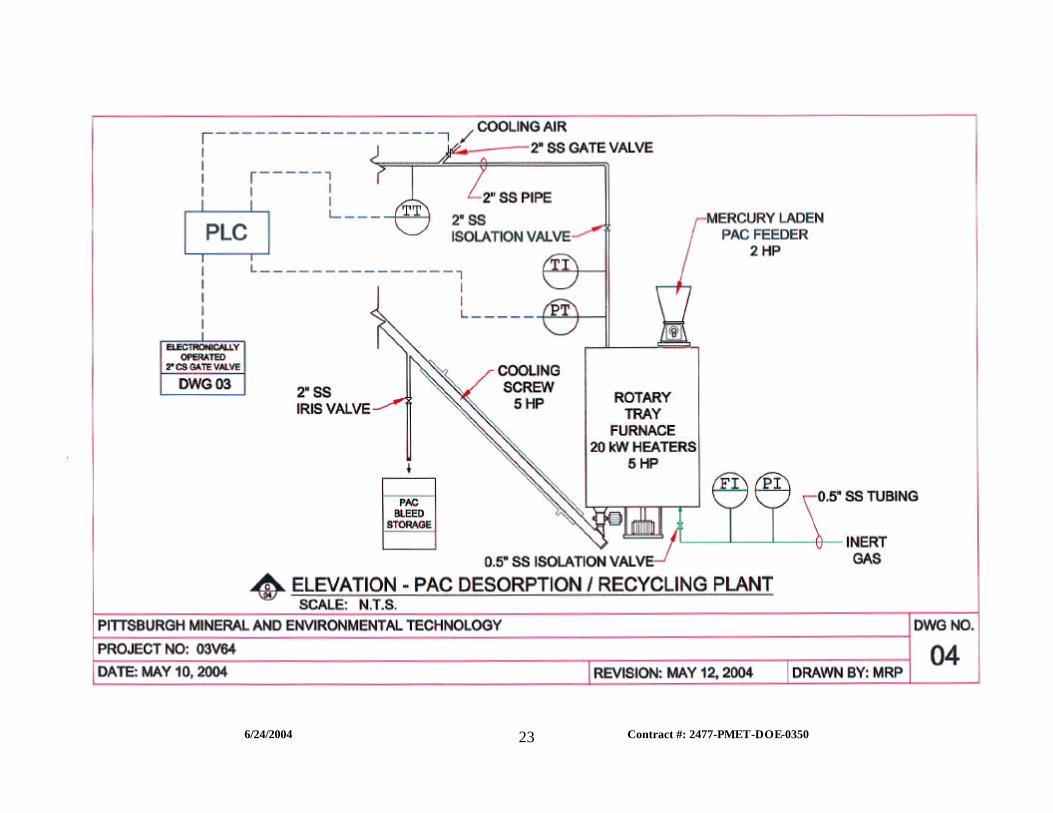
Drawing 4 – P&ID-A . . . . . . . . . . . . . . 23
Drawing 5 – P&ID-B . . . . . . . . . . . . . . 24
6/24/2004 Contract #: 2477-PMET-DOE-0350
1
INTRODUCTION This project addresses the removal and recovery of mercury that is sorbed to Powdered Activated Carbon (PAC) to remove mercury from coal combustion power plant flue gas streams.
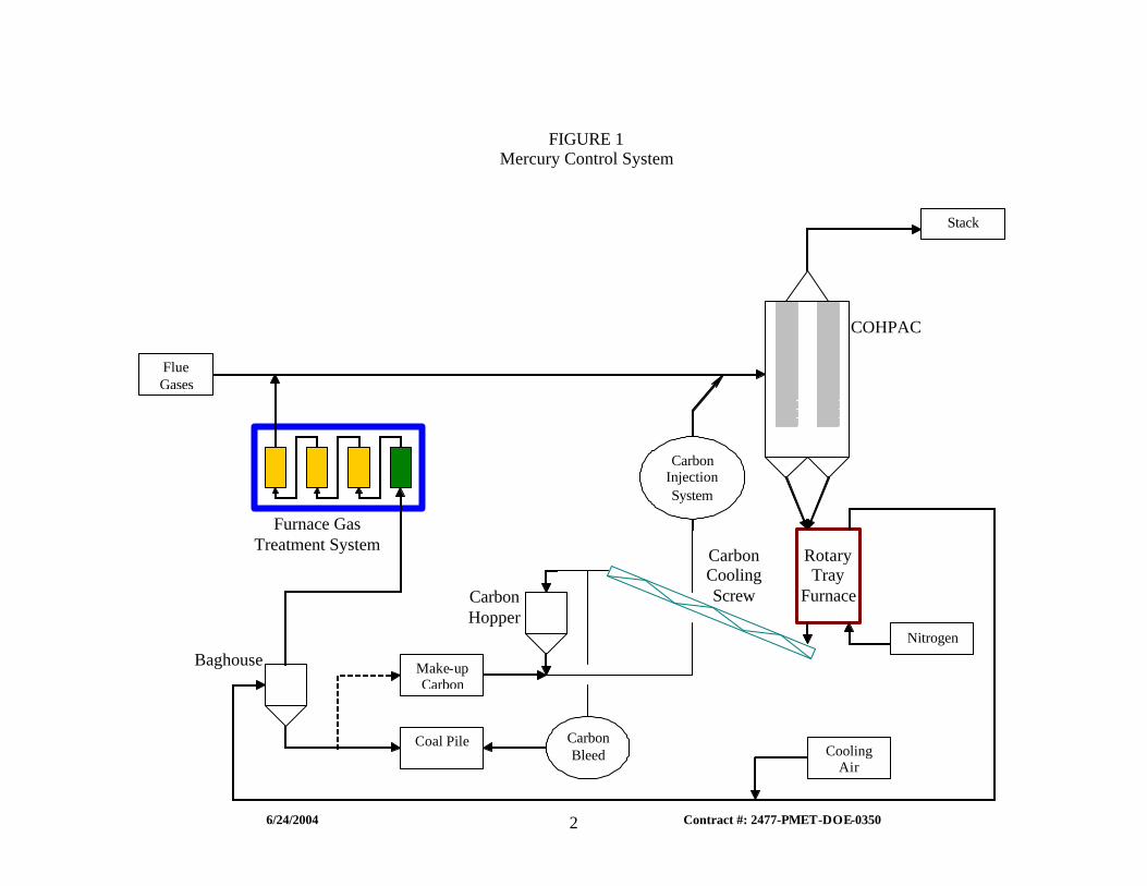
Previous work performed by ADA ES and others for the US DOE has demonstrated the effectiveness of injecting PAC into flue gas streams for mercury removal. This approach has been highly successful in removing up to 80% of the mercury from the flue gas when the PAC is injected ahead of a COHPAC facility. To date, the PAC with sorbed mercury is assumed to be disposed after use. This will result in a significant expense for the mercury removal, since the most effective PAC employed to date is DARCO FGD manufactured by Norit Americas is estimated to cost approximately $0.50/ pound delivered to the power plant. In addition to the purchase expense, the disposal of this material may potentially fall under regulations requiring its disposal in “special” or hazardous waste landfills. The proposed approach dramatically reduces the need for ongoing PAC purchases and provides for a thousand fold concentration of mercury in a specially formulated carbon that can subsequently be treated for mercury recovery as a salable metal, thus avoiding any disposal of potentially toxic waste streams. The estimated operating cost for this process is ~$0.05/lb of treated PAC compared with a purchase price of $0.50/lb PAC and an unknown but potentially significant disposal cost. The process is shown in schematic in Figure 1.
6/24/2004 Contract #: 2477-PMET-DOE-0350
2
FIGURE 1 Mercury Control System
Carbon Hopper
Furnace Gas Treatment System
COHPAC
Rotary Tray
Furnace
Carbon Cooling Screw
Flue Gases
Make-up Carbon
Nitrogen
Stack
Baghouse
Coal Pile
Carbon Injection System
Carbon Bleed Cooling
Air
6/24/2004 Contract #: 2477-PMET-DOE-0350
3
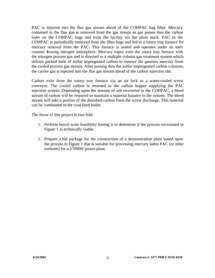
PAC is injected into the flue gas stream ahead of the COHPAC bag filter. Mercury contained in the flue gas is removed from the gas stream as gas passes thru the carbon layer on the COHPAC bags and exits the facility via the plant stack. PAC in the COHPAC is periodically removed from the filter bags and fed to a rotary tray furnace for mercury removal from the PAC. This furnace is sealed and operates under an inert counter flowing nitrogen atmosphere. Mercury vapor exits the rotary tray furnace with the nitrogen process gas and is directed to a multiple column gas treatment system which utilizes packed beds of sulfur impregnated carbon to remove the gaseous mercury from the cooled process gas stream. After passing thru the sulfur impregnated carbon columns, the carrier gas is injected into the flue gas stream ahead of the carbon injection site. Carbon exits from the rotary tray furnace via an air lock to a water-cooled screw conveyor. The cooled carbon is returned to the carbon hopper supplying the PAC injection system. Depending upon the amount of ash recovered in the COHPAC, a bleed stream of carbon will be required to maintain a material balance in the system. The bleed stream will take a portion of the desorbed carbon from the screw discharge. This material can be combusted in the coal- fired boiler. The focus of this project is two fold:
1. Perform bench scale feasibility testing is to determine if the process envisioned in Figure 1 is technically viable.
2. Prepare a bid package for the construction of a demonstration plant based upon
the process in Figure 1 that is suitable for processing mercury laden PAC (or other sorbents) for a 270MW power plant.
6/24/2004 Contract #: 2477-PMET-DOE-0350
4
EXECUTIVE SUMMARY
The Environmental Protection Agency (EPA) has decided to regulate mercury emissions from coal fired power plants. The regulations will be developed and finalized, with full compliance anticipated by 2007. Test work performed by others has identified a system by which the mercury in flue gases can be captured onto Powdered Activated Carbon (PAC) to control mercury emissions. However, the existing production capacity for PAC is only 10% of the capacity required for full implementation. The process envisioned and defined in this project enables the reuse of PAC after its injection and collection from a flue gas stream in which the PAC injection point is after the electrostatic precipitators but prior to a baghouse. Once collected, the PAC is thermally treated in an inert atmosphere to desorb the contained mercury allowing the PAC to be returned to the injection system for reuse. The desorbed mercury is sequestered and concentrated for recovery into saleable product. Based upon the results from the bench-scale feasibility testing in this report, the envisioned process is technically viable when the thermal desorption operation occurs under the following parameters:
• Inert atmosphere during elevated temperature processing; • 550°C desorption temperature; and • 30 minutes of retention at temperature
Using this process, PAC can be recycled at least 10 times without any degradation of the sorption characteristics. Based upon the operating parameters established above, a bid package was prepared for the construction of a demonstration plant suitable for processing mercury laden PAC (or other sorbents) for a 270MW power plant. Use of the PAC desorption/recycling system will decrease the yearly operating costs by at least $216,200 resulting in a return-on- investment (uninstalled capital basis) of 28.14%. Compared to single-pass PAC that is injected once, collected and disposed of; this process offers:
• Significant yearly operating cost savings, • Reduced PAC consumption to stretch the existing supply, • Mercury emissions that are recyclable, and • Eliminated environmental liability from landfilled mercury laden PAC.
6/24/2004 Contract #: 2477-PMET-DOE-0350
5
SECTION 1 BENCH SCALE FEASIBILITY TESTING
PURPOSE AND SCOPE The purpose of bench scale feasibility testing is to determine if the process envisioned in Figure 1 is technically viable. The criteria for this determination are:
• Will the PAC physically degrade when exposed to air at elevated temperatures? • Will the PAC retain its sorptive properties when exposed to several desorption
cycles? • Can mercury be desorbed from the loaded PAC?
In order to answer these questions the following scope of work was carried out:
• Acquisition of a virgin PAC from Norit Americas (DARCO FGD). • Acquisition of a mercury laden PAC that was produced from an operating
mercury control system. The virgin PAC used in this control system was also Norit’s DARCO FGD.
• Generate a synthetically mercury loaded PAC for testing. • Generate temperature versus loss in mass data for PAC in air. • Produce thermally cycled model PAC for sorptive properties testing. • Perform mercury desorption on the synthetically loaded sample. • Perform mercury desorption on the field sample of mercury loaded PAC. • Perform sorption characteristic testing on the starting and thermally cycled PAC
for comparison.

6/24/2004 Contract #: 2477-PMET-DOE-0350
6
SAMPLE ACQUISITION Two PAC samples (supplied by ADA-ES) were acquired from a coal fired power plant operating a mercury control system in which the PAC is injected into the flue gas down stream of the ESP’s and prior to a baghouse. Referred to as SITE hereinaft er.
• PMET RFA# 4444-1 o 10 gallon sample: Received on 9/23/03
• PMET RFA# 4444-3 o 5 gallon sample: Received on 12/29/03
GENERATION OF SYNTHETICALLY LOADED PAC Prior to the arrival of the SITE sample material, a synthetically loaded PAC (DARCO FGD, the same grade of PAC used at SITE) was generated. One gram of HgCl2 and Hg were blended into coarse sand. This material and PAC were introduced into an apparatus to transfer the mercury compounds from the sand to the PAC. One 24 hour transfer test generated 250g of PAC that contained 6.4 ppm of total mercury, which is similar to what is expected at the SITE. The transfer apparatus is depicted in Figure 2.
FIGURE 2
A: Mercury laden sand. B: PAC ¼” thick. C: Sulfur impregnated carbon for mercury exhaust control.
Vacuum Blower
Ambient Air
B C A
1um Bag Filters and Housings.

6/24/2004 Contract #: 2477-PMET-DOE-0350
7
TESTING OF THE MODEL PAC Two series of thermal treatments of the model PAC were performed. Both of these treatments were performed in air rather than nitrogen to study the reactivity of the carbon at various temperatures. The oxidation of the carbon was tracked by the loss in weight of the sample when the material was subjected to air at temperature for 60 minutes. The results of these tests are shown in Figure 3.
FIGURE 3
PAC Loss in Weight vs Temperature
0.00%
10.00%
20.00%
30.00%
40.00%
50.00%
60.00%
70.00%
80.00%
0 100 200 300 400 500 600 700 800
Temp (C)
Lo
ss in
Wei
gh
t
Some loss in weight (~5%) occurs at temperatures up to 200oC, and above 250oC the carbon reacts vigorously with essentially all of the available carbon being oxidized. This particular PAC sample (DARCO FGD) has an ash content of approximately 25%.

6/24/2004 Contract #: 2477-PMET-DOE-0350
8
Figure 4 shows the loss in weight for a PAC sample exposed to air at 250oC.
FIGURE 4
PAC Loss in Weight @ 250C vs. Time at Temperature
5.40%
5.50%
5.60%
5.70%
5.80%
5.90%
6.00%
6.10%
6.20%
6.30%
6.40%
6.50%
0 10 20 30 40 50 60 70
Time (min)
Lo
ss in
Wei
gh
t
Figure 4 shows that even at a modest temperature of 250oC; the sample material undergoes oxidation of the carbon at a fairly constant rate of 0.016% Loss in Weight per minute exposed. Clearly this testing indicates that an inert atmosphere is required for the tray desorption furnace to avoid significant losses of the PAC material during mercury desorption.
6/24/2004 Contract #: 2477-PMET-DOE-0350
9
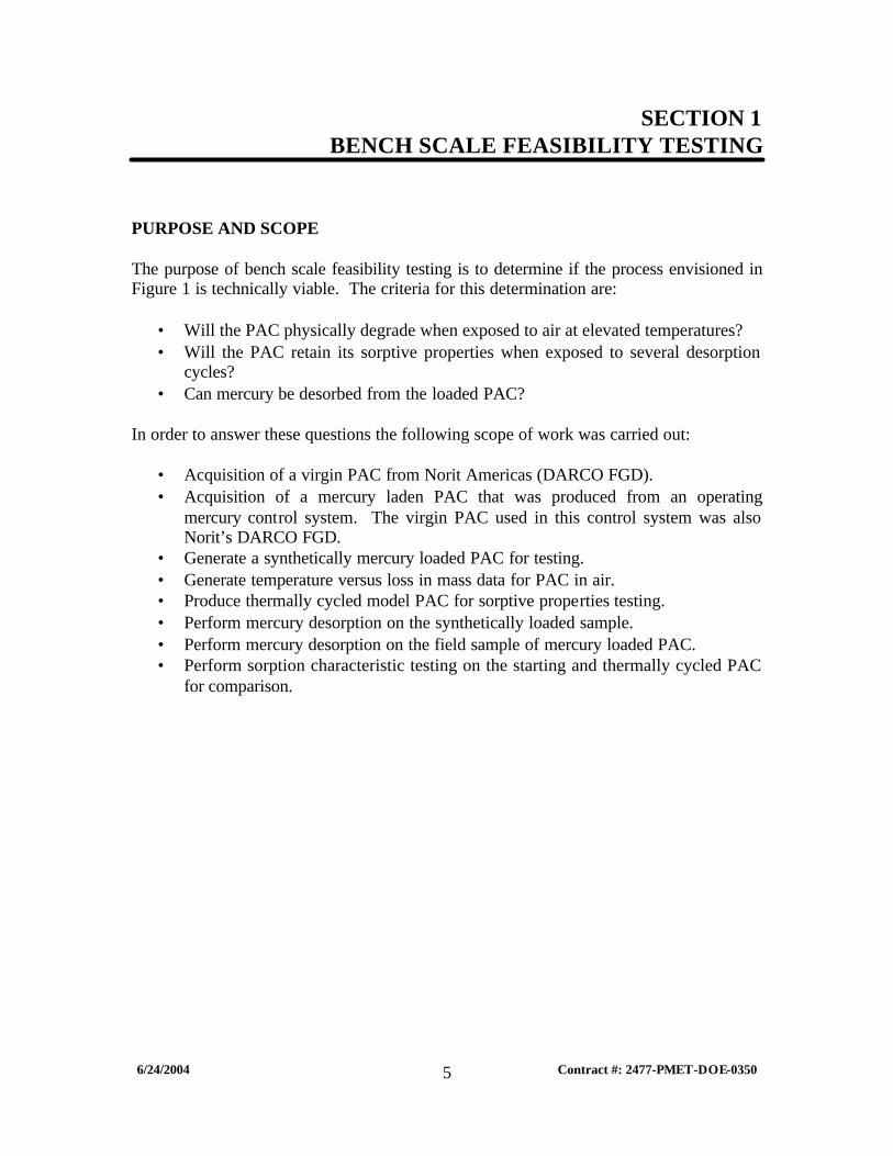
One thermal desorption test was performed using an inert atmosphere (nitrogen) in which the model PAC was cycled from ambient to 450°C ten times to simulate multiple recycles in the commercial system. Figure 5 shows the change in carbon sorption capacity and surface area over the ten cycles.
FIGURE 5
Thermal Treatments
400
450
500
550
600
650
700
0 1 2 3 4 5 6 7 8 9 10
Cycles (Ambient - 400C - Ambient)
Iodine No.BET Surface Area (m2/g)Series3
The weight loss of the model PAC over the ten cycles was less than 0.1%.
6/24/2004 Contract #: 2477-PMET-DOE-0350
10
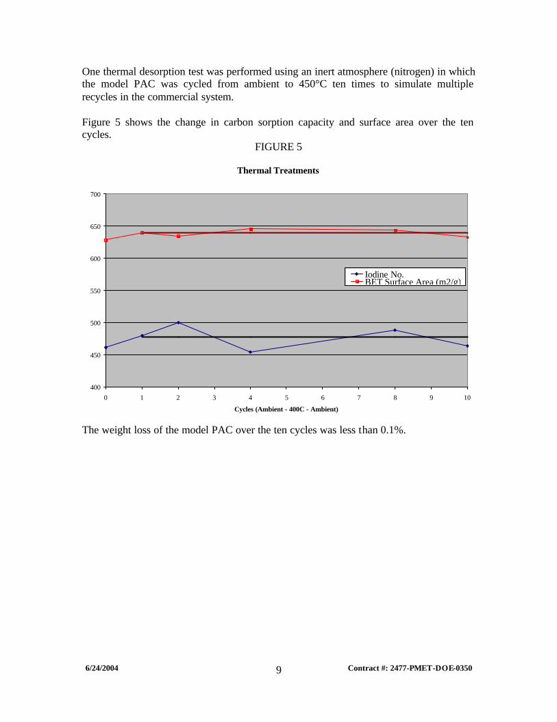
Figure 6 shows the nitrogen isotherm comparison of the model PAC and cycled PAC (10 thermal desorption cycles).
FIGURE 6
Isotherm
0.000
50.000
100.000
150.000
200.000
250.000
300.000
350.000
400.000
450.000
0.00E+00 2.00E-01 4.00E-01 6.00E-01 8.00E-01 1.00E+00 1.20E+00
Relative Pressure (P/Po)
Vol
ume
(cc/
g)
Head Cycled
Figure 7 shows the pore size distribution comparison of the model PAC and cycled PAC (10 thermal desorption cycles).
FIGURE 7
Pore Size Distribution
0.00E+00
2.00E-01
4.00E-01
6.00E-01
8.00E-01
1.00E+00
1.20E+00
1.00 10.00 100.00 1000.00 10000.00
Pore Diameter (A)
Des
orpt
ion
Dv[
log
d] (c
c/g)
Head Cycled

6/24/2004 Contract #: 2477-PMET-DOE-0350
11
Comparison of the “Area-Volume-Pore Size” Data
Analysis Head PAC Recycled PAC Multipoint BET 605.9 m2/g 603.7 m2/g Single Point BET 616.3 m2/g 613.6 m2/g t-Method External Surface Area 257.9 m2/g 257.9 m2/g t-Method Micro Pore Surface Area 348.0 m2/g 345.8 m2/g Total Pore Volume for pores with dia. < 390Å @ P/Po = 0.9475
0.5689 cc/g 0.5676 cc/g
t-Method Micro Pore Volume 0.1750 cc/g 0.1734 cc/g Average Pore Diameter 37.56 Å 37.61 Å
Another thermal desorption test was run, in which the synthetically loaded PAC was subjected to conditions that would mimic a commercial rotary tray furnace.
• The loaded model PAC was placed into a tray to a depth of ½”. • This tray was placed into a retort oven and the nitrogen purge was started. • The sample was ramped to 400°C in 15 minutes and held at temperature for 15
minutes. • The sample was allowed to cool to 200°C over 60 minutes. • The sample was then removed and agitated. • This thermal desorption cycle was repeated 4 times using the same PAC sample.
After 15 minutes thermal desorption the total mercury was reduced to 0.38 ppm, and after 30 minutes the total mercury was reduced to <0.1 ppm.

6/24/2004 Contract #: 2477-PMET-DOE-0350
12
SITE SAMPLE TESTING The as received PAC was assayed for mercury and LOI (Loss On Ignition). Sample ID Mercury Content (ppm) LOI (%) 4444-1 37.9 24.5 4444-3 35.3 19.0 Virgin PAC 0.1 75.7 The SITE PAC is loaded with mercury; however it also contained a large amount of ash. This must be fine ash that was not collected by the ESPs and allowed to pass to the COHPAC where it is collected with the injected PAC. Fine ash escaping from the ESPs must be minimized in order for the PAC to be recycled. The mercury laden PAC was thermally desorbed at 450°C, 550°C, 650°C and 750°C in an inert atmosphere to simulate a commercial furnace.
Sample 4444-1 Mercury Desorption Data
Mercury Concentration (ppm) Elapsed Time in Furnace (min) 450°C 550°C 650°C 750°C
0 37.9 37.9 37.9 37.9 30 9.54 BDL BDL BDL 60 8.24 BDL BDL BDL
BDL < 0.01 ppm Hg
Sample 4444-3 Mercury Desorption Data
Mercury Concentration (ppm) Elapsed Time in Furnace (min) 450°C 550°C 650°C 750°C
0 35.3 35.3 35.3 35.3 30 14.4 BDL BDL BDL 60 12.3 BDL BDL BDL
BDL < 0.01 ppm Hg Mercury was successfully stripped from both samples at 550°C and higher. However, the mercury was not completely removed from the PAC at 450°C.

6/24/2004 Contract #: 2477-PMET-DOE-0350
13
CONCLUSIONS When PAC is exposed to air at elevated temperatures, it clearly starts to physically degrade. This degradation occurs by the partial oxidation of the carbon structure. In order for the proposed process to function properly, the mercury desorption operation must occur in an inert atmosphere such as nitrogen, argon or helium. As evidenced by the testing performed on virgin PAC and PAC that was thermally cycled 10 times to simulate multiple passes through the mercury desorption operation, the sorption characteristics of the cycled PAC remained unchanged in comparison the virgin PAC. Whether it was the synthetically loaded PAC or the SITE sample, the attached mercury is able to be desorbed from the PAC to levels less than 0.01ppm. The SITE sample required temperatures in excess of 500°C for 30 minutes during the desorption operation. Since the boiling points of mercury and mercury chloride are below 450°C, it can be surmised that an active binding agent exists in the SITE PAC. This could occur if other halogens (such as Fluorine) existed in the flue gas. The envisioned process is technically viable when the thermal desorption operation occurs under the following parameters:
• Inert atmosphere during elevated temperature processing; • 550°C desorption temperature; and • 30 minutes of retention at temperature.
6/24/2004 Contract #: 2477-PMET-DOE-0350
14
SECTION 2 BID PACKAGE
PURPOSE AND SCOPE The purpose of this section is to generate a bid package that would enable a reputable engineering firm to cost out the procurement and installation of a pilot-plant within 20% of the actual cost. The following items were produced as part of the bid package:
• Mass Balance • Process Flow Diagram (PFD) • Equipment List • General Arrangement Drawing • Elevation Drawing • Process and Instrumentation Diagrams (P&IDs)
A budgetary economic evaluation was also produced to compare this process to single-pass injection, collection and disposal options. MASS BALANCE The mercury control system that is installed at Alabama Power E.C. Gaston1 was used as the baseline case for the mass balance. Other criteria used as the basis for the mass balance include:
• 270 MW boiler • 80% boiler capacity factor • 1,000,000 acfm of flue gas to the COHPAC (baghouse) • 80% mercury removal efficiency • 1.5 lbs of PAC per MMacf of flue gas • 6,700 operating hours per year • $0.50 per pound of virgin PAC • 20% PAC bleed rate • 1.15 COHPAC loading factor
The mass balance and PFD was produced using the data produced in SECTION 1 along with the baseline case and basis points.

6/24/2004 Contract #: 2477-PMET-DOE-0350
15

6/24/2004 Contract #: 2477-PMET-DOE-0350
16
To aid in the viewing of this document, the following enlargement of the mass balance is included.
Stream Number 1 2 3 4 5 Stream Label Flue Gas 1 Flue Gas 2 Flue Gas 3 COHPAC
Solids COHPAC
Gas
6 Desorbed Carbon
Temperature (C) 124 124 124 124 124 550 Gas (acfm) 500,000 500,089 500,089 0.00 500,089 - Hg (kg/day) 0.2142 0.2160 0.2160 0.1728 0.0432 - Water (kg/day) - - - - - - Oxygen (kg/day) 600,730 601,656 601,656 - 601,656 - Nitrogen (kg/day) 13,604,000 13,607,057 13,607,057 - 13,607,057 - Carbon Dioxide (kg/day) 5,342,900 5,342,900 5,342,900 - 5,342,900 - Ash (kg/day) 466.56 466.56 2,332.86 2,332.86 - 2,216.22 Carbon (kg/day) - - 979.94 979.94 - 930.94 Total Solids (kg/day) 466.77 466.78 3,313.02 3,312.97 0.04 3,147.16 Carbon Content (%) - - 29.58% 29.58% - 29.58% Mercury Content (ppm) 0.0110 0.0110 0.0110 52.1526 0.0022 -
Stream Number 7 8 9 10 11 12 Stream Label Nitrogen Mercury Gas
1 Cooling Air Mercury Gas
2 Baghouse
Gas Baghouse
Solids
Temperature (C) 20 550 20 49 49 49 Gas (acfm) 0.18 0.18 89.29 89.47 89.47 - Hg (kg/day) - 0.1728 - 0.1728 0.1728 - Water (kg/day) - - - - - - Oxygen (kg/day) - - 925.70 925.70 925.70 - Nitrogen (kg/day) 8.38 8.38 3,048.62 3,057.00 3,057.00 - Carbon Dioxide (kg/day) - - - - - - Ash (kg/day) - 116.64 - 116.64 - 116.64 Carbon (kg/day) - 49.00 - 49.00 - 49.00 Total Solids (kg/day) - 165.81 - 165.81 0.17 165.64 Carbon Content (%) - 29.55% - 29.55% - 29.58% Mercury Content (ppm) - 1042.0374 - 1042.0374 - -
Stream Number 13 14 15 16 17 18 19 Stream Label Carbon Bleed Recycled
Carbon Make-Up Carbon
Carbon Injection
Treated Furnace Gas
Cooling Water In
Cooling Water Out
Temperature (C) 200 200 20 184 49 20 40 Gas (acfm) - - - - 89.47 - - Hg (kg/day) - - - - 0.0017 - - Water (kg/day) - - - - - 16,376 16,376 Oxygen (kg/day) - - - - 925.70 - - Nitrogen (kg/day) - - - - 3,057.00 - - Carbon Dioxide (kg/day) - - - - - - - Ash (kg/day) 466.56 1,749.66 0.00 1,866.30 - - - Carbon (kg/day) 195.99 734.95 195.99 979.94 - - - Total Solids (kg/day) 662.55 2,484.61 195.99 2,846.24 - - - Carbon Content (%) 29.58% 29.58% 100.00% 34.43% - - - Mercury Content (ppm) - - - - 0.4338 - -
6/24/2004 Contract #: 2477-PMET-DOE-0350
17
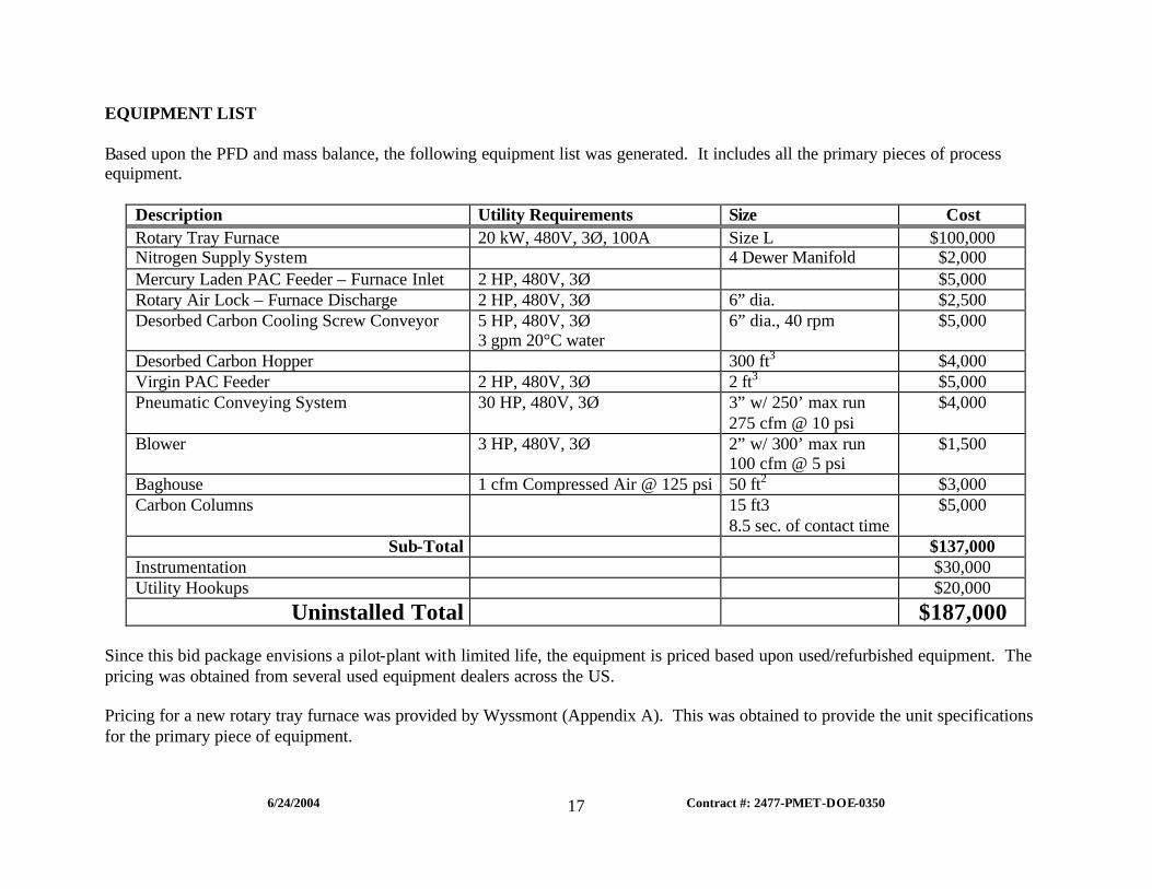
EQUIPMENT LIST Based upon the PFD and mass balance, the following equipment list was generated. It includes all the primary pieces of process equipment.
Description Utility Requirements Size Cost Rotary Tray Furnace 20 kW, 480V, 3Ø, 100A Size L $100,000 Nitrogen Supply System 4 Dewer Manifold $2,000 Mercury Laden PAC Feeder – Furnace Inlet 2 HP, 480V, 3Ø $5,000 Rotary Air Lock – Furnace Discharge 2 HP, 480V, 3Ø 6” dia. $2,500 Desorbed Carbon Cooling Screw Conveyor 5 HP, 480V, 3Ø
3 gpm 20°C water 6” dia., 40 rpm $5,000
Desorbed Carbon Hopper 300 ft3 $4,000 Virgin PAC Feeder 2 HP, 480V, 3Ø 2 ft3 $5,000 Pneumatic Conveying System 30 HP, 480V, 3Ø 3” w/ 250’ max run
275 cfm @ 10 psi $4,000
Blower 3 HP, 480V, 3Ø 2” w/ 300’ max run 100 cfm @ 5 psi
$1,500
Baghouse 1 cfm Compressed Air @ 125 psi 50 ft2 $3,000 Carbon Columns 15 ft3
8.5 sec. of contact time $5,000
Sub-Total $137,000 Instrumentation $30,000 Utility Hookups $20,000
Uninstalled Total $187,000 Since this bid package envisions a pilot-plant with limited life, the equipment is priced based upon used/refurbished equipment. The pricing was obtained from several used equipment dealers across the US. Pricing for a new rotary tray furnace was provided by Wyssmont (Appendix A). This was obtained to provide the unit specifications for the primary piece of equipment.

6/24/2004 Contract #: 2477-PMET-DOE-0350
18
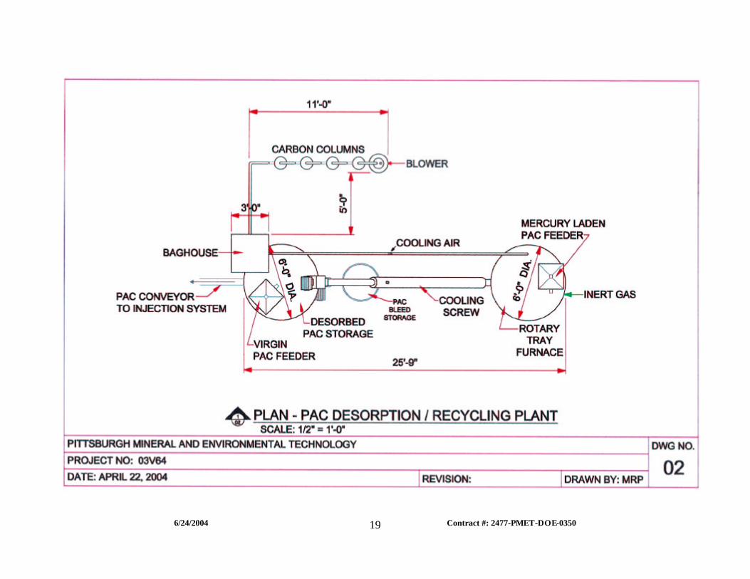
GENERAL ARRANGEMENT DRAWING Once the equipment was specified, it was laid out as if the pilot-plant site had a large (40’ x 40’) and level plot for installation. The original CAD drawing is to scale however, to make it fit within the 8.5” by 11” size format the drawing was compressed and is no longer to scale.
6/24/2004 Contract #: 2477-PMET-DOE-0350
19
6/24/2004 Contract #: 2477-PMET-DOE-0350
20
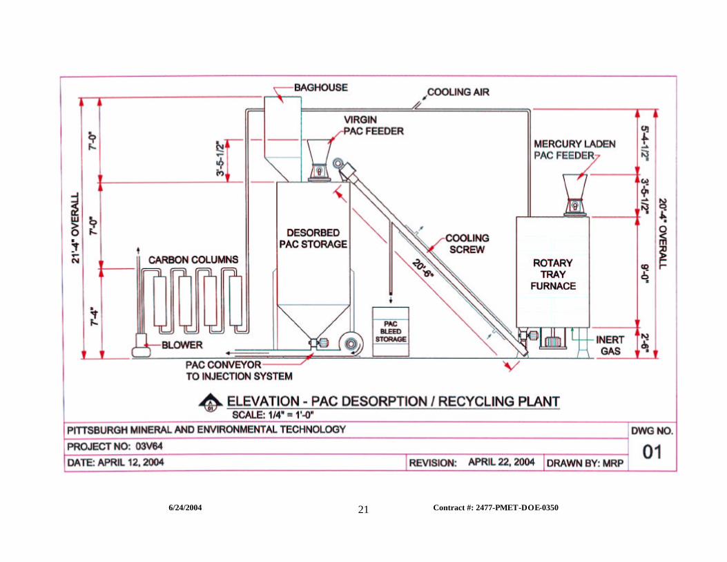
ELEVATION DRAWING In order to show the elevations of all the pieces of equipment, the elevation drawing arrangement does not match the general arrangement drawing. The original CAD drawing is to scale however, to make it fit within the 8.5” by 11” size format the drawing was compressed and is no longer to scale.
6/24/2004 Contract #: 2477-PMET-DOE-0350
21
6/24/2004 Contract #: 2477-PMET-DOE-0350
22
PROCESS AND INSTRUMENTATION DIAGRAMS
6/24/2004 Contract #: 2477-PMET-DOE-0350
23

6/24/2004 Contract #: 2477-PMET-DOE-0350
24
6/24/2004 Contract #: 2477-PMET-DOE-0350
25
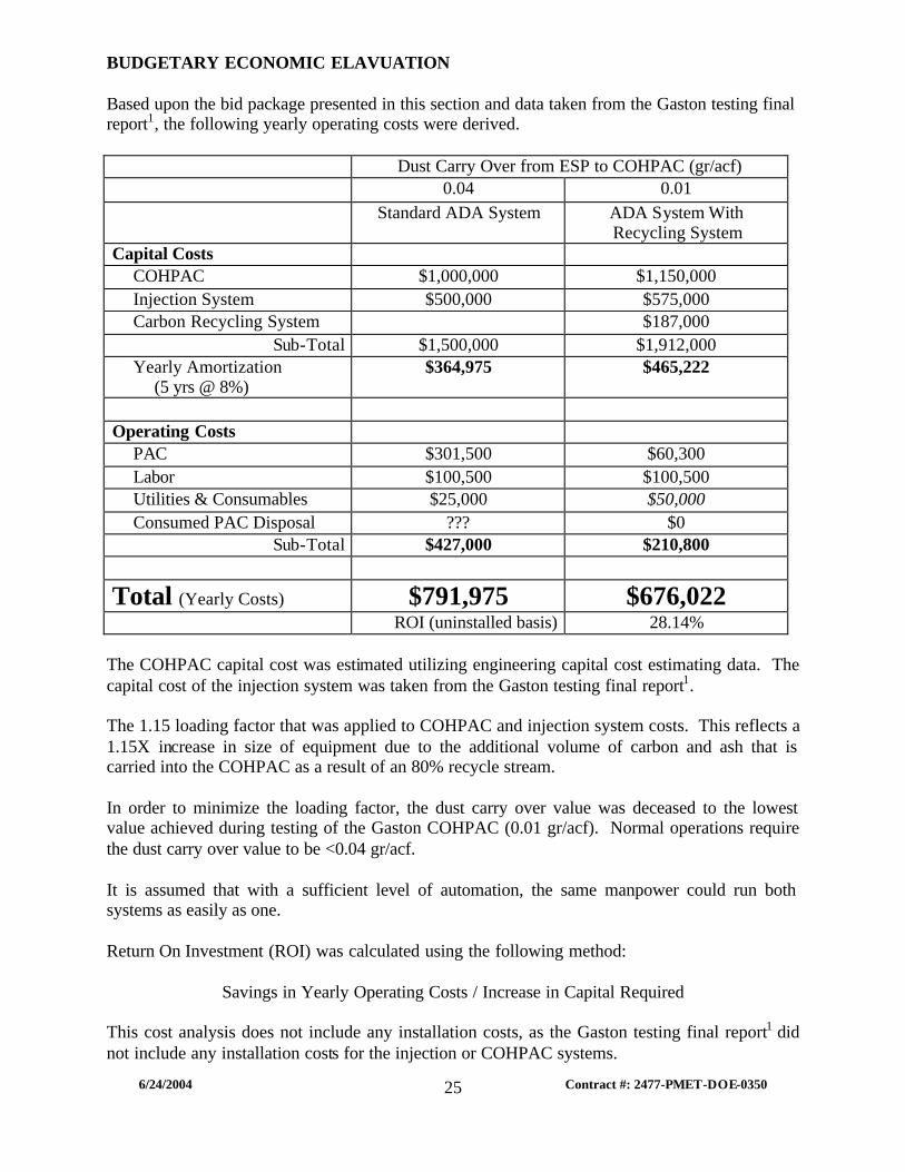
BUDGETARY ECONOMIC ELAVUATION Based upon the bid package presented in this section and data taken from the Gaston testing final report1, the following yearly operating costs were derived.
Dust Carry Over from ESP to COHPAC (gr/acf) 0.04 0.01
Standard ADA System ADA System With Recycling System
Capital Costs COHPAC $1,000,000 $1,150,000 Injection System $500,000 $575,000 Carbon Recycling System $187,000
Sub-Total $1,500,000 $1,912,000 Yearly Amortization
(5 yrs @ 8%) $364,975 $465,222
Operating Costs
PAC $301,500 $60,300 Labor $100,500 $100,500 Utilities & Consumables $25,000 $50,000 Consumed PAC Disposal ??? $0
Sub-Total $427,000 $210,800
Total (Yearly Costs) $791,975 $676,022 ROI (uninstalled basis) 28.14%
The COHPAC capital cost was estimated utilizing engineering capital cost estimating data. The capital cost of the injection system was taken from the Gaston testing final report1. The 1.15 loading factor that was applied to COHPAC and injection system costs. This reflects a 1.15X increase in size of equipment due to the additional volume of carbon and ash that is carried into the COHPAC as a result of an 80% recycle stream. In order to minimize the loading factor, the dust carry over value was deceased to the lowest value achieved during testing of the Gaston COHPAC (0.01 gr/acf). Normal operations require the dust carry over value to be <0.04 gr/acf. It is assumed that with a sufficient level of automation, the same manpower could run both systems as easily as one. Return On Investment (ROI) was calculated using the following method:
Savings in Yearly Operating Costs / Increase in Capital Required This cost analysis does not include any installation costs, as the Gaston testing final report1 did not include any installation costs for the injection or COHPAC systems.
6/24/2004 Contract #: 2477-PMET-DOE-0350
26
It should be noted that this budgetary economic evaluation does not include any cost to dispose of the consumed PAC from the standard ADA mercury control system. This cost could range from $12/ton2 (fly ash) to $1,200/ton2 (mercury containing hazardous waste). This could result in an additional $360,000 in yearly operating costs. In utilizing the PAC recycling system, the mercury is removed from the PAC prior to the bleed point which allows the spent PAC to be used for fuel value in the boiler avoiding all disposal costs. CONCLUSIONS The loading factor value is very sensitive to the fine ash carry over. It is extremely important that the ESP’s are operating at maximum capacity so that the COHPAC, injection system and PAC desroption/recycling systems are not over loaded with material. Ultimately this will affect the process economics as the loading factor increases the size and cost of the systems. Use of the PAC desorption/recycling system will decrease the yearly operating costs by $216,200. The capital required to install the PAC desorption/recycling system will be paid for in less than four years. If mercury contaminated PAC is disposed of as hazardous waste, there is some future concern with regard to liability. There are numerous examples of instances when mercury containing materials were disposed of using the guidelines for that period of time; however as time passed the guidelines changed resulting in landfills that are now tagged as “Superfund” sites. Some of the parties responsible for the generation of the material that resides in those landfills are now liable for damages and/or cleanup costs. Use of the PAC desorption/recycling system removes all mercury liability from the spent PAC.
6/24/2004 Contract #: 2477-PMET-DOE-0350
27
REFERENCES
1. C. Bustard, S. Sjostrom, S. Renninger, L. Monroe Ph.D., R. Miller, R. Chang Ph.D. “Full-Scale Evaluation of Mercury Control with Sorbent Injection and COHPAC at Alabama Power E.C. Gaston”. www.adaes.com/publications/Gaston Paper Final 2001-30-02.pdf, January 30, 2002.
2. L. Monroe, J. Cichaniwicz, G. Offen. “UARG Comments on Process Inputs for EPA’s
Planned IPM Modeling Runs”. www.epa.gov/ttnatw01/combust/utiltox/uarg ipm comments.doc, April 19, 2002.

6/24/2004 Contract #: 2477-PMET-DOE-0350
28
APPENDIX A
6/24/2004 Contract #: 2477-PMET-DOE-0350
29
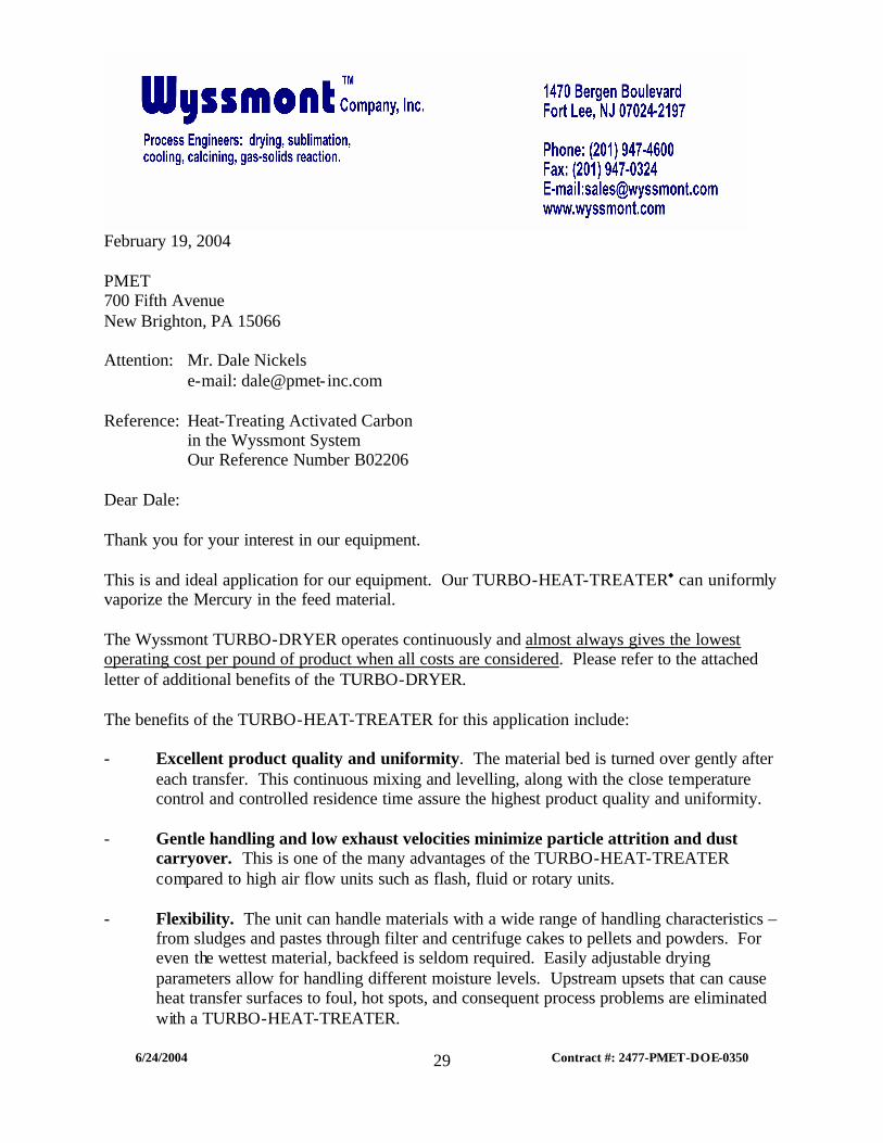
February 19, 2004 PMET 700 Fifth Avenue New Brighton, PA 15066 Attention: Mr. Dale Nickels e-mail: dale@pmet- inc.com Reference: Heat-Treating Activated Carbon in the Wyssmont System Our Reference Number B02206 Dear Dale: Thank you for your interest in our equipment. This is and ideal application for our equipment. Our TURBO-HEAT-TREATER® can uniformly vaporize the Mercury in the feed material. The Wyssmont TURBO-DRYER operates continuously and almost always gives the lowest operating cost per pound of product when all costs are considered. Please refer to the attached letter of additional benefits of the TURBO-DRYER. The benefits of the TURBO-HEAT-TREATER for this application include: - Excellent product quality and uniformity. The material bed is turned over gently after
each transfer. This continuous mixing and levelling, along with the close temperature control and controlled residence time assure the highest product quality and uniformity.
- Gentle handling and low exhaust velocities minimize particle attrition and dust
carryover. This is one of the many advantages of the TURBO-HEAT-TREATER compared to high air flow units such as flash, fluid or rotary units.
- Flexibility. The unit can handle materials with a wide range of handling characteristics –
from sludges and pastes through filter and centrifuge cakes to pellets and powders. For even the wettest material, backfeed is seldom required. Easily adjustable drying parameters allow for handling different moisture levels. Upstream upsets that can cause heat transfer surfaces to foul, hot spots, and consequent process problems are eliminated with a TURBO-HEAT-TREATER.
6/24/2004 Contract #: 2477-PMET-DOE-0350
30
-2-
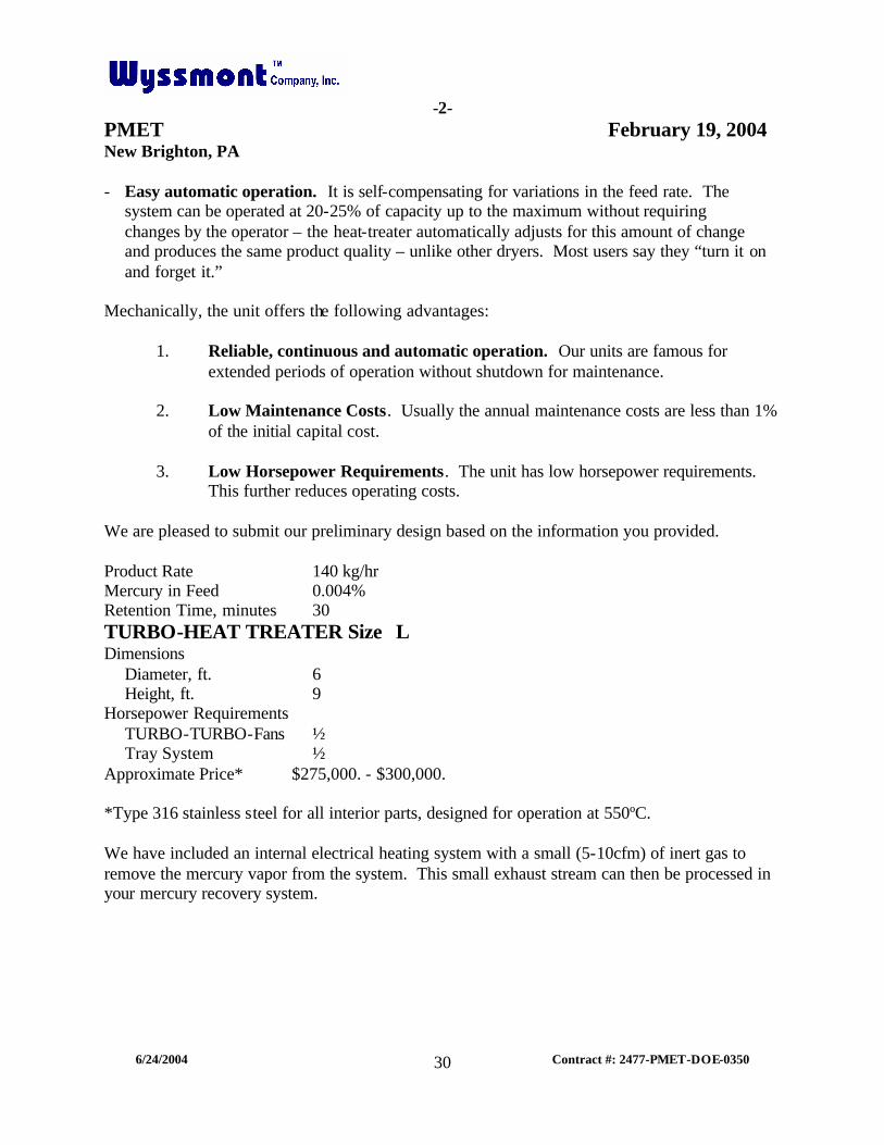
PMET February 19, 2004 New Brighton, PA - Easy automatic operation. It is self-compensating for variations in the feed rate. The system can be operated at 20-25% of capacity up to the maximum without requiring changes by the operator – the heat-treater automatically adjusts for this amount of change and produces the same product quality – unlike other dryers. Most users say they “turn it on and forget it.” Mechanically, the unit offers the following advantages:
1. Reliable, continuous and automatic operation. Our units are famous for extended periods of operation without shutdown for maintenance.
2. Low Maintenance Costs. Usually the annual maintenance costs are less than 1%
of the initial capital cost.
3. Low Horsepower Requirements. The unit has low horsepower requirements. This further reduces operating costs.
We are pleased to submit our preliminary design based on the information you provided. Product Rate 140 kg/hr Mercury in Feed 0.004% Retention Time, minutes 30 TURBO-HEAT TREATER Size L Dimensions Diameter, ft. 6 Height, ft. 9 Horsepower Requirements TURBO-TURBO-Fans ½ Tray System ½ Approximate Price* $275,000. - $300,000. *Type 316 stainless steel for all interior parts, designed for operation at 550ºC. We have included an internal electrical heating system with a small (5-10cfm) of inert gas to remove the mercury vapor from the system. This small exhaust stream can then be processed in your mercury recovery system.
6/24/2004 Contract #: 2477-PMET-DOE-0350
31
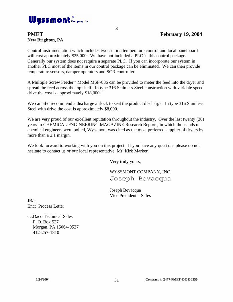
-3-
PMET February 19, 2004 New Brighton, PA Control instrumentation which includes two-station temperature control and local panelboard will cost approximately $25,000. We have not included a PLC in this control package. Generally our system does not require a separate PLC. If you can incorporate our system in another PLC most of the items in our control package can be eliminated. We can then provide temperature sensors, damper operators and SCR controller. A Multiple Screw Feeder→ Model MSF-836 can be provided to meter the feed into the dryer and spread the feed across the top shelf. In type 316 Stainless Steel construction with variable speed drive the cost is approximately $18,000. We can also recommend a discharge airlock to seal the product discharge. In type 316 Stainless Steel with drive the cost is approximately $8,000. We are very proud of our excellent reputation throughout the industry. Over the last twenty (20) years in CHEMICAL ENGINEERING MAGAZINE Research Reports, in which thousands of chemical engineers were polled, Wyssmont was cited as the most preferred supplier of dryers by more than a 2:1 margin. We look forward to working with you on this project. If you have any questions please do not hesitate to contact us or our local representative, Mr. Kirk Marker. Very truly yours, WYSSMONT COMPANY, INC.
Joseph Bevacqua Joseph Bevacqua Vice President – Sales JB/jt Enc: Process Letter cc:Daco Technical Sales P. O. Box 527 Morgan, PA 15064-0527 412-257-1810