processing of nanostructured wc-co powders and …9346/fulltext01.pdf · processing of...
TRANSCRIPT

Processing of Nanostructured WC-Co Powders
and Sintered Steels This thesis is based on the following papers: Paper I
Zongyin Zhang and M. Muhammed, Thermochemical decomposition of cobalt doped ammonium paratungstate precursor, Thermochimica acta, Vol. 400, 2003, p235-245.
Paper II
Zongyin Zhang, Y. Zhang and M. Muhammed, The reduction of cobalt doped ammonium paratungstate to nanostructured W-Co powder, International Journal of Refractory Metals and Hard Materials, Vol. 20, 2002, p227-233.
Paper III
Zongyin Zhang, S. Wahlberg, M. Wang and M. Muhammed, Processing of nano-structured W-Co powder from precursor obtained by co-precipitation, Nano-Structured Materials, Vol. 12, 1999, p163-166.
Paper IV
Zongyin Zhang, R. Sandström, K. Frisk and A. Salwén, Characterization of Intermetallic Fe-Mn-Si powders produced by casting and mechanical ball milling, submitted to Powder Technology.
Paper V
Zongyin Zhang, R. Sandström and L. Wang, Modelling of swelling of Fe-Cu compacts sintered at temperatures above the copper melting point, submitted to Journal of Materials Processing Technology.
Paper VI
Zongyin Zhang and R. Sandström, Fe-Mn-Si master alloy steel by powder metallurgy processing, Journal of alloys and compounds, in press.
Paper VII
Zongyin Zhang, K. Frisk, A. Salwén and R. Sandström, Mechanical properties of Fe-Mo-Mn-Si-C sintered steels, submitted to Powder Metallurgy.

Contents 1. Introduction................................................................................................................... 1
1.1 Powder metallurgy technology and nanostructured materials .................................. 1 1.2 Objective of present work......................................................................................... 3
2. WC-Co hard materials ................................................................................................. 7 2.1 WC-Co materials produced by conventional method............................................... 7 2.2 Nanostructured WC-Co powder and sintered materials ......................................... 14
3. Grinding kinetics of powders..................................................................................... 18 3.1 General introduction ............................................................................................... 18 3.2 Grinding models...................................................................................................... 19 3.3 First order equation ................................................................................................. 20 3.4 Higher order equations............................................................................................ 20
4. Swelling of Fe-Cu alloy sintered at the temperatures above Cu melting point..... 26 4.1 Variation of swelling with copper content.............................................................. 26 4.2 Effect of carbon on the swelling ............................................................................. 28 4.3 Effect of porosity, particle size, prealloyed powder and alloying additives ........... 30
5. Sintered steels with copper, manganese, molybdenum and silicon elements ........ 35 5.1 Liquid phase sintering of powder metallurgy steels ............................................... 35 5.2 Master alloy techniques used in powder metallurgy steels..................................... 40 5.3 Properties of copper, manganese, molybdenum and silicon sintered steels ........... 42
6. Summary of included papers ..................................................................................... 46
6.1 Nanostructured W-Co and WC-Co powders (Paper I, II and III)........................... 46
6.2 Sintered steels (Paper IV, V, VI and VII) ............................................................... 52
7. Conclusions.................................................................................................................. 62
8. Acknowledgements ..................................................................................................... 64
References........................................................................................................................ 65

1
1. Introduction
1.1 Powder metallurgy technology and nanostructured materials
Powder metallurgy is the art and science of producing metal powders and of the
utilization of metal powders for the production of massive materials and shaped objects
[1], and one of the advanced technologies in the development of material science and
engineering. Powder metallurgy is at the same time an antique technology. The time
when powder metallurgy was first used dates back to ancient time. Examples are gold
powder by the Incas, iron powder by the Egyptians and the Delhi column in India [1].
Modern powder metallurgy started with the invention of the production of tungsten
filament and tungsten carbide base hard materials. The latter led to a revolution in the
tool industry.
Advantages of powder metallurgy are low consumption of energy, high utilization of
materials, low cost, and rapid and high volume production [1]. In the last two decades,
many new materials with unique properties have been produced such as Nd-Fe-B
permanent magnetic material, superconduting material, some nanostructured powders and
sintered products. Most products by powder metallurgy only need limited amount of
machining. Powder metallurgy technology can be used for producing various types of
materials. For example, porous material, self-lubricating bearing, metal filter, porous
electrode, and refractory metal, magnetic and electric material, superalloy, sintered steel,
ceramic, and composite etc. Some products cannot be produced by conventional
technology, for instance, the materials have large difference in their melting point
although they are mutually dissolved in the liquid state, or the element composition
exceeds its solubility in the basic metal or complete immiscibility systems such as W-Cu,
W-Ag, and Cu-C materials [2]. Some materials produced by powder metallurgy
technology have better properties and more efficiency than those produced by
conventional technique such as some superalloys and high-speed steels.
Nanostructured materials have been extensively investigated in the past decades, and are
still a most interesting topic. Nanostructured materials, also called nanophase materials,
nanocrystalline materials, and supramolecular solids, have a structure in the size less than

2
100 nm in at least one dimension. This type of materials can be divided into four
categories according to the dimension [3]: 1) zero dimension: atom cluster, and cluster
assemblies; 2) one dimension: nanotube and nanowire; 3) two dimension: thin film,
multilayers and overlayers materials; and 4) three dimension: equiaxed nanostructured
materials, and nanoscale powder agglomerates. Chemical composition was also used for
distinguishing the nanostructured materials, In which the nanostructured materials were
distinguished as 1) uniform chemical composition of both all crystallines and interfacial
region; 2) different ones and compositional variation between all crystallines and
interfacial region; and 3) segregation between elements for example in immiscible system
[4].
Nanostructured materials have unique properties compared to coarser-grained materials.
These materials show a significant fraction of grain boundaries, large ratio of interface
area to volume, and a high degree of disorder of atoms, which result in varying
mechanical, chemical, and physical properties. Nanostructured materials can have
improved strength, hardness, ductility, toughness, specific heat, and enhanced diffusivity
etc, in comparison to materials made by conventional process [3]. The properties of
nanostructured materials are influenced by grain size, dimensionality of system, alloying
degree of the component, the atomic structure, pore formation and other crystal lattice
defects.
The variation of the hardness and strength of a material with the grain size can be
expressed by the Hall-Petch equation. It takes into account the difficulty in creating
dislocations in small grains and the impedance of the motion of dislocation at the grain
bourdary [5, 6]:
Hv = Hy + Kd-1/2 (1.1)
Where Hv is the hardness, Hy the intrinsic stress resisting dislocation motion, d the grain
diameter, and K a constant.
Dislocations in the materials are activated to move by applied stresses. The density of
dislocations increases during deformation. The barriers to dislocations such as fine

3
Fig. 1. The hardness of nanostructured copper increases with decreasing grain size [8].
particles, dispersions, grain boundaries, point defects, solute atoms, make dislocation
motion difficult, and increase hardness and strength. When the materials have nanoscale
grain size, grain boundaries play the role as very effective barriers to dislocation motion
[7]. The hardness and strength increase with reduction in grain size is smaller in
nanometer regime than at the micrometer scale. Thus K in Eq (1.1) is smaller in the
former case. The hardness of nanostructured copper increases with decreasing grain size
as shown in Fig. 1 [8].
1.2 Objective of present work
In the present thesis, modern powder metallurgy technique is used to study the production
of nanostructured W-Co and WC-Co powders from chemically synthesized W-Co
precursors, the grinding kinetics of Fe-Mn-Si powder by mechanical ball milling, the
mechanical properties of Fe-Mn-Si master alloy sintered steel, and the modeling of
expansion of Fe-Cu sintered steels sintered at the temperatures above melting point of
copper.
4
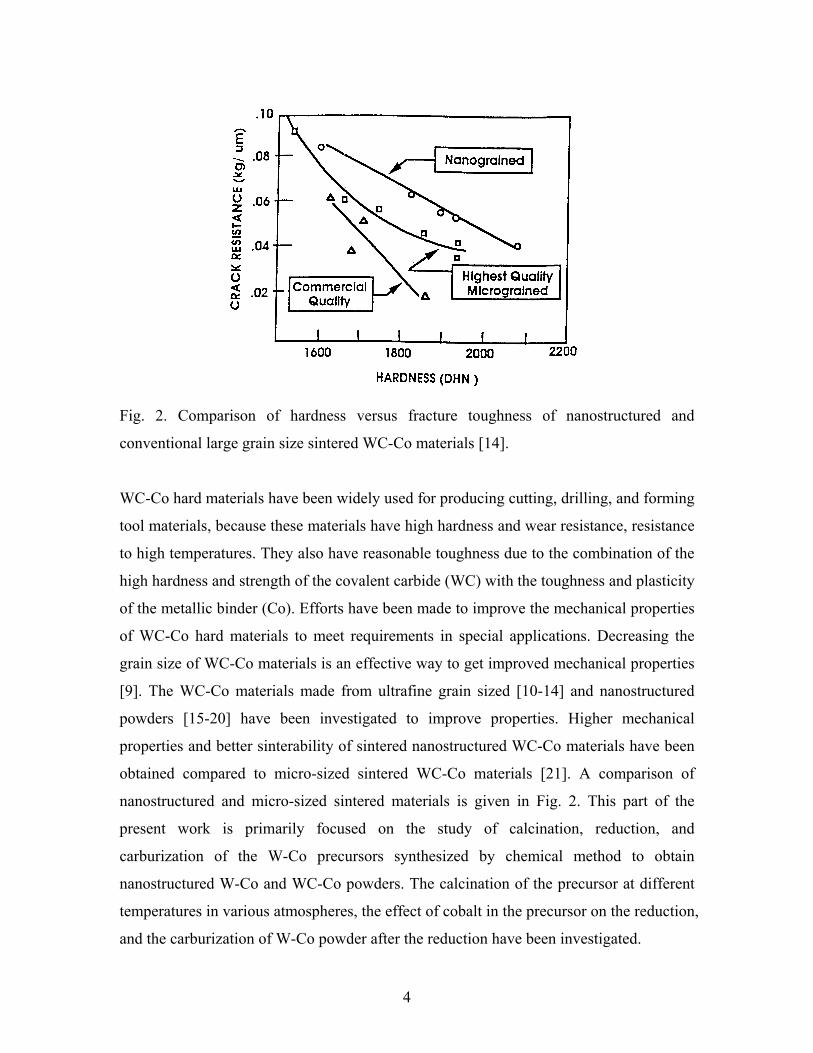
Fig. 2. Comparison of hardness versus fracture toughness of nanostructured and
conventional large grain size sintered WC-Co materials [14].
WC-Co hard materials have been widely used for producing cutting, drilling, and forming
tool materials, because these materials have high hardness and wear resistance, resistance
to high temperatures. They also have reasonable toughness due to the combination of the
high hardness and strength of the covalent carbide (WC) with the toughness and plasticity
of the metallic binder (Co). Efforts have been made to improve the mechanical properties
of WC-Co hard materials to meet requirements in special applications. Decreasing the
grain size of WC-Co materials is an effective way to get improved mechanical properties
[9]. The WC-Co materials made from ultrafine grain sized [10-14] and nanostructured
powders [15-20] have been investigated to improve properties. Higher mechanical
properties and better sinterability of sintered nanostructured WC-Co materials have been
obtained compared to micro-sized sintered WC-Co materials [21]. A comparison of
nanostructured and micro-sized sintered materials is given in Fig. 2. This part of the
present work is primarily focused on the study of calcination, reduction, and
carburization of the W-Co precursors synthesized by chemical method to obtain
nanostructured W-Co and WC-Co powders. The calcination of the precursor at different
temperatures in various atmospheres, the effect of cobalt in the precursor on the reduction,
and the carburization of W-Co powder after the reduction have been investigated.

5
Fig. 3. Influence of alloying elements on hardness of ferrite [2].
Sintered steels are alloys based on iron, with intentionally added alloying elements, often
with carbon made by powder metallurgy technique [2]. The needs for these types of
materials are increasing in the market because of the property improvements and new
technical innovations. The alloying elements mostly used in powder metallurgy sintered
steels are copper, nickel and molybdenum because the requirement of sintering
atmosphere is not critical [22-25]. However, the high costs of the elements and low
strength have limited the application of these steels. Manganese, chromium, vanadium
have been used in powder metallurgy sintered steels by master alloy technique in which
the carbides of the elements have been formed to prevent them from oxidation or by
prealloying technique [26-30]. Manganese and silicon are two of the most useful
elements in conventional steel production due to low cost, abundant resource and high
strengthening effect to iron. The effect of alloying elements on hardness of ferrite is
presented in Fig. 3 [2]. Although manganese steels and silicon steels have been studied
for a long time, combining manganese with silicon into sintered steel has only been
studied for about a decade [31-33]. But these sintered steels have not been extensively
produced due to the sensitivity of manganese and silicon to the sintering atmosphere. The
aim of this part of the work is mainly to investigate the mechanical properties of sintered
Fe-Mn-Si and Fe-Mo-Mn-Si sintered steels using master alloy technique to obtain good

6
performance for high strength applications. The properties of milled Fe-Mn-Si alloy
powders were also studied, and a model has been used to describe the grinding kinetics of
Fe-Mn-Si master alloy powders.
Sintered Fe-Cu-C alloy are very common steels used in automobiles due to easy
production of the powders, acceptable cost and medium strength. However, the swelling
of Fe-Cu alloy when sintering at the temperatures above the melting point of copper has
limited the use of this type of sintered steels for more precise parts [34-37]. This swelling
problem has bothered powder metallurgist and scientist for more than fifty years.
Expansion mechanisms have been studied and it was concluded that the prime
mechanism is liquid copper penetrating into the boundaries between iron particles and/or
within iron grains, causing abnormal swelling [38-40]. So far, the driving force for this
swelling mechanism has not been clarified yet, and the most phenomena related to this
swelling such as the effects of W, WO3, other oxides, and prealloyed additives on the
swelling of Fe-Cu compacts cannot be reasonably explained. In this study, a model is
presented how swelling of Fe-Cu sintered alloy at the copper melting point varies with
green density and copper content. The influence of diffusion, heating rate and particle
size is also considered.

7
2. WC-Co hard materials
2.1 WC-Co materials produced by conventional method
WC base hard materials have been widely used in many areas such as rock drilling,
cutting tools, wear parts, drawing dies, rod mill roll, seal rings, and nozzles since they
were discovered in the 1920’s. The material type has been developed into a big family by
introducing additional carbides of titanium, tantalum, niobium, chromium, vanadium, and
molybdenum, to improve properties such as oxidation resistance, hot hardness, and hot
strength. The major component in this type material is a hard phase such as WC with a
certain amount of binder cobalt, which gives relatively tough properties and also
increases sintered density and binding strength. WC-Co alloys have been used as a main
component in the hard material group due to several reasons [41]:
• The availability of high-quality raw materials;
• The high standard of manufacturing and high product reliability;
• High strength and rigidity, excellent thermal conductivity, and low thermal expansion,
making them into ideal coating substrate;
• The possibility of tailor-making the substrate simply by variations in powders and/or
in sintering technology;
• The possibility of material reclamation through well-developed recycling processes.
The production of tungsten carbide sintered components involves several steps as follows:
• Preparation of WC powder;
• Powder compaction;
• Densification by liquid-phase sintering;
• Post-treatment.

8
Fig. 4. WC-Co phase diagram [53].
2.1.1 Properties of WC-Co hard materials
The mechanical properties of WC hard materials depend on the composition, binder
content, carbide grain size, grain size distribution, as well as sintering temperature,
sintering time, and sintering atmosphere [42-48]. Adjusting the carbide-to-binder ratio
and the average grain size of the carbide phase influences different properties such as
hardness, strength, rigidity, toughness etc. Examples of properties of WC-Co hard alloys
are shown in Table I [49].
Table I. Properties of WC-Co hard alloys [49]

9
The properties of WC-Co materials are improved by the liquid phase sintering of cobalt
[50-52]. The WC-Co binary phase diagram is shown in Fig. 4 [53]. When the compacts
are sintered at certain temperature, a liquid of cobalt forms. A rapid densification occurs
due to the capillary force exerted on the solid WC particles by the wetting liquid.
Meanwhile, pores are eliminated through minimising the total surface energy of the
system.
Milman et al [54, 55] studied the relationship between hardness and grain size of WC-Co
materials, and pointed out that the hardness decrease with increasing grain size follows a
Hall-Petch relationship, as shown in equation (1.1). The mechanical properties,
microstructure and sintering of WC-Co hard materials made from fine powders have also
been studied [10-14]. Ultrafine-grain sized WC-Co materials showed higher bending
strength value [14]. An investigation [9] has shown that reducing the particle size can
improve the properties of WC-Co hard materials. Generally, rapid grain growth of the
sintered body occurs during sintering of WC-Co compacts at high temperatures [10, 11].
Hence, inhibitors such as VC, Cr3C2, NbC etc were added to WC-Co compacts for
controlling the grain size in the required range, and obtaining better mechanical
properties [12, 13, 56-59].
2.1.2 Production of WC powder
Carburization of reduced tungsten powders is the most common method in the
conventional tungsten carbide powder production [60-62]. The process is summarized in
Fig. 5 [63]. In this method, the particle size of WC powders can vary in the range
between 0.15 µm and 12 µm [41]. The investigations have been focused on the reduction
and carburization [65-68]. Tungsten carbide is then mixed with cobalt by milling,
pressing, and sintering to obtain WC-Co materials. The properties of the reduced tungsten
powders determine the size distribution of the tungsten carbide powders [61,41,64]. The
carburization kinetics is affected by the particle size of tungsten powders because
diffusion and carburization rates are controlled by this parameter [64]. Controlling the

10
Fig. 5. The processing steps in the production of tungsten carbide [63].
particle size of tungsten powder is important for successful sintering and subsequent
treatment. Particle size also influences the grain size of the sintered tungsten carbide,
which in turn controls the strength and toughness of the products.
Fig. 6 shows the relationship between the particle size of W powder, particle/grain size of
the derived WC, and the WC grain size in the sintered hard materials [41]. The W-C
phase diagram [69] is presented in Fig. 7. It can be seen that tungsten monocarbide has a
very narrow homogeneity range and decomposes peritectically at 2776°C. Hence,
controlling carbon content during carburization is important for obtaining WC powder.
There exists another tungsten carbide, hemicarbide W2C in the phase diagram.
Hemicarbide W2C is also obtained as an intermediate phase during the carburization
process. The carburization temperature influences the subgrain size and micro-hardness
of WC, which are important for the mechanical properties of WC-Co alloys.
2.1.3 Production of tungsten powder
Tungsten powder can be obtained by the reduction of tungsten oxides, ammonium
paratungstate (APT) or ammonium metastungstate (AMT). Ammonium paratungstate and
tungsten trioxide (WO3) are common raw materials in the production of tungsten powder
[70-79]. Generally, if the starting materials are APT and AMT, the calcination or
reductive decomposition step is needed. Fouad et al [80] suggested that calcination at
400ºC should be performed before the reduction of APT.

11
Fig. 6. Relationship between particle size of W powder, particle/grain size of the derived
WC, and WC grain size in the sintered hard materials [41].
Fig. 7. W-C phase diagram [69].

12
Calcination process has been used in the production of most powders as a pre-treatment
step or final process [73, 81-83]. The same chemical precursor after calcination can give
different products at different temperatures, which leads to different properties of final
products. In some cases, calcination of the precursors underwent the structure
transformation from amorphous to crystalline, and from crystalline to amorphous again
[82, 83], which influences characteristics of the calcined products such as specific surface
area, phase constituent, and phase amount [22, 82, 84], and affects the followed reduction
process.
The calcination of ammonium paratungstate (APT) or ammonium metastungstate (AMT)
in flowing air was carried out, and it had been shown that thermal decomposition of APT
occurs in successive steps, in which AMT forms from APT in the first step. APT
decomposes into AMT at temperatures between 180 and 225°C [85, 86]. Comparing the
decomposition of APT and AMT from room temperature to high temperature, the
decomposition temperature ranges shifted and different weight losses can be obtained due
to different ammonia and water contents in APT and AMT. The thermalgravimetric
analysis (TGA) curves of APT and AMT are shown in Fig. 8. In general, pure yellow
WO3 is obtained after the decomposition of both APT and AMT in air at the temperatures
between 440 and 500°C. However, a small degree of reduction producing traces of WO2.9
always occurred when the calcination was carried out in flowing nitrogen. Amorphous
phase powders form at medium temperature ranges from the decomposition of APT and
AMT. Schubert et al [73] investigated the reduction of APT calcined at different
temperatures and in different atmospheres, and found that the physical and chemical
properties of the oxides are controlled by calcination temperature, exposure time and the
reductivity of the calcination atmosphere. They pointed out that the initial decomposition
stage determines the consistency and purity of the final tungsten powder.
Direct reduction of APT in hydrogen has also been studied [87-89]. At low temperatures,
APT is reduced to tungsten blue oxide, which is a mixture of different compounds such
as ammonium tungsten bronze (ATB), hydrogen tungsten bronze (HTB), tungsten
trioxide (WO3), tungsten β-oxide (WO2.9 or W20O58), and tungsten γ-oxide (WO2.72 or
W18O49). Van Put and Zeger reviewed the properties of tungsten blue oxide formed

13
Fig. 8 Thermalgravimetric analysis curves of ammonium paratungstate (left) and
ammonium metatungstate (right) [85, 86].
during the reduction of APT between 300 and 600°C [90]. The reduction of APT at high
temperatures showed different behaviour depending on the processing parameters and the
characteristics of APT [73, 79, 91]. Fouad et al [76] studied hydrogen reduction of APT,
and suggested that in a stepwise reduction procedure, APT is reduced to form α-W via
the intermediate phases, (NH4)0.33WO3, WO2 with a small amount of H0.33WO3 and/or
WO3. In another study [74], it was indicated that the transformation of APT at low
temperatures (at 220ºC) to amorphous powder, and then to y(NH4)2O·WO3·zH2O with
(x/2)(NH4)2O·WO3-x/2 (at 300ºC).
The size of tungsten particle significantly depends on the starting materials [68, 70, 71,
78, 91], and reduction conditions (temperature, time, atmosphere) [63, 68, 71-73, 78, 79].
Increasing reduction temperature and time can improve reduction rate of the powders
[74], and increasing temperature is more effective than increasing reduction time.
The reduction of the other tungsten oxides has also been studied such as tungsten β-oxide
(WO2.9) [68, 71], tungsten γ-oxide (WO2.72) [71, 78], tungsten dioxide (WO2) [71],
tungsten blue oxide (TBO) [70, 71, 79], and ammonium tungsten bronze (ATB) [68, 78].
The reduction process of WO2.9 to α-W is quite sensitive to temperature and hydrogen
purity. There are four reduction paths i. e. via 1) WO2.72 and WO2; 2) WO2.72; 3) β-W;
and directly to α-W [68, 71]. WO2.72 can directly be reduced to α-W [77, 84] and also via

14
β-W and via WO2 [71]. The reduction rate is much higher if direct reduction of WO2.72 to
α-W occurs. In most studies, it is suggested that WO2 can only be reduced to α-W
without forming β-W, which is the dominating step in the reduction of tungsten oxides to
W since the reduction rate is very slow [71]. Schubert and Lassner [73] demonstrated that
all the oxides could be reduced to α-W with a high reaction rate if WO2 does not form
during reduction, otherwise a low reaction rate will be obtained.
Several intermediate phases, WO2.9, WO2, WO2.72, β-W will possibly form during the
reduction of ATB to α-W [68, 73]. Zou et al [68] pointed out that the formation rate of α-
W from ATB is much faster than that from WO3. The reduction path of TBO is
dependent on its composition. The α-W phase can form from the reduction of the TBO
(WO2.9, WO2.72) powder in the temperature range of 800-1000ºC via WO2 [79], which
was also reported by Liao et al [78] from the TBO (25%WO2.9, 75%WO2.72) powder.
However, in the reduction of another TBO (60%WO3, 40%WO2.9), WO3 firstly
transforms to WO2.9 and then after WO2.9 was reduced via WO2 to α-W [78]. The
reduction of TBO and WO3 shows slight difference in the nucleation of the WO2.72 phase
[70].
There are two reduction mechanisms in the reduction of WO2 to α-W, a nucleation-
growth mechanism and a chemical vapour transition (CVT) mechanism. The former
occurs in the reduction process at low temperatures (500-700°C), and the latter exists in
the process at high temperatures reduction (700-1000°C) [71]. The overall reduction
process is controlled by the transformation of WO2 into α-W. If the intermediate phase
formation of WO2 can be avoided, for example, the direct transformation of WO2.72 into
α-W, the reduction can proceed at a much higher reduction rate. The present study has
considered the catalytic role of cobalt in the reduction of the tungsten oxides, which can
at least increase the transformation rate of WO2 into α-W.
2.2 Nanostructured WC-Co powder and sintered materials
Decreasing the grain size can improve the mechanical properties of sintered WC-Co
materials. A comparison of properties of WC-Co hard materials with different grain sizes
in the micron range is shown in Table II. Nanostructured WC-Co materials have been

15
extensively studied because finer grain size resulting from nanostructured WC-Co
powders leads to improved properties of sintered components [92-94]. To obtain very
fine particle size for improving the properties, nanostructured WC-Co powders have been
investigated [20, 21, 93, 95-98]. Better mechanical properties and better sinterability of
sintered tungsten carbides materials with nanostructured powders have been obtained
compared to those with micro-sized powders, as shown in Fig. 2.
Table II A comparison of properties of WC-Co hard materials with different grain sizes
in the micron range [9].
Composition Grain Size
Hardness
HRA
Density
kg/m3
Transverse
Strength (MPa)
Compression
Strength (MPa)
94WC-6Co Fine 92.5-93.1 15000 2210 5930
94WC-6Co Medium 91.7-92.2 15000 2000 5450
94WC-6Co Coarse 90.5-91.5 15000 1790 5170
90WC-10Co Fine 90.7-91.3 14600 3100 5170
90WC-10Co Coarse 87.4-88.2 14500 2760 4000
Nanostructured WC-Co powders have mainly been made by thermo-chemical methods, i.
e. chemically made W-Co precursors are reduced and carburised with or without
calcination to form nanostructured WC-Co powders [84, 95, 99]. Chemical methods for
synthesizing W-Co powders have several advantages [95]:
• Cobalt can be mixed with tungsten homogeneously at the molecular level;
• Cobalt content can be varied in a large range;
• The grain size of the processed powders can be reduced to nanoscale;
• Rapid liquid phase sintering gives nanostructured WC-Co materials.
WC-Co powders with compositions from 5 to 30 % Co have been obtained using the
solution mixtures of Co(en)3WO4 and H2WO4 in spray conversion processing [21, 92, 95,

16
99-101]. The processing conditions of the synthesis, reduction, and carburization of the
precursors were investigated.
A suspension of APT and Co(OH)2 was used to make W-Co precursors with a chemical
coprecipitation synthesis method, in which the cobalt composition can vary in a wide
range [102, 103]. Other methods to produce WC-Co precursors have also been studied
[104, 86]. Different routes for the production of nanostructured WC-Co powders from the
W-Co precursors by chemical methods were studied [102-106].
In general, nanostructured WC-Co powder are obtained from the W-Co precursor by the
multi-step processes that involve precursor calcination, reduction, and carburization.
Calcination can be done in air, reduction in hydrogen, and carburization in carbon
monoxide or a mixture of carbon monoxide and carbon dioxide. Calcination and
reduction can be combined into one step, a so-called reductive decomposition of the
precursor. Recently, a single step process has also been investigated in which calcination,
reduction, and carburization can be performed in one atmosphere. This atmosphere is
comprised of a mixture of hydrogen and carbon monoxide or hydrogen and methane.
Hydrogen is used for reduction and carbon monoxide or methane for carburization [75,
107]. Among the processing parameters, temperauture is one of the most important
factors. High temperatures and long times normally lead to large particle size and a large
degree of agglomeration.
Cobalt influences both the reduction and the carburization processes in the production of
nanostructured WC powders [84, 93], which are different from the conventional process
of producing W and WC powders. The cobalt phase can affect reduction and
carburization by the catalytic decomposition of CO gas [93] although some unwanted
intermediate phases are formed [84]. Hence, increasing cobalt content leads to a decrease
in reduction and carburization times, but also increases the particle size by agglomeration
in the final products.
Lower reduction and carburization temperatures (< 700°C) are used in the production of
nanostructured WC powder. Particle agglomeration and growth occur at higher
temperatures. One of tungsten phases, β-W (W3O), must be noted when reduction is
performed at lower temperatures. The formation of β-W and its effect on the following
steps were studied [71, 108-111]. β-W exists at temperatures below 650°C. During the

17
reduction of WO3, low temperature, dry hydrogen will first yield WO2.9 as an
intermediate phase, before β-W is formed as a final product.
Gao et al [105] showed that carburization of β-W to WC is difficult. This is due to the
very fast transition process from β-W to W2C, even at relatively low temperatures. Once
a well-crystallized W2C has formed, prolonged exposure to CO, even at a higher
temperature, only produce small amount of WC. The carburization mechanism is shown
in Fig. 9.
Fig. 9. Carburization mechanism for α-W (a-c) and β-W (d-f) [105].

18
3. Grinding kinetics of powders
3.1 General introduction
Milling processes have been widely used in the production of fine and ultra-fine powders
in the pharmaceutical, ceramic, cosmetic, and chemical industries. Products with unique
properties can be produced such as nanosized, amorphous, nonequilibrium structured
powders. Mechanical milling is the only way to produce some intermetallic powders,
which cannot be produced by conventional techniques. The effects of operation
parameters such as ball size, density, milling time, milling rate, milling aids and energy
input on the milling process have been studied. Different types of mills including ball
mill [112], fluid energy mill [113], roll mill [114], stirred media mill [115-117], vibratory
ball mill [118] have been considered.
The characteristics of milled materials such as hardness, ductile, feed powder size or
powder size distribution also affect the milled process. Brittle powders and ductile
powders show different milling mechanisms. The different behaviour was discussed
during different materials milling [119-122]. Aluminum, copper and brass showed three
milling stages, flattening, abrasion, breakage [119], while brittle materials only
experienced two breakage mechanisms in the milling process [120]. Koch and
Whittenberger [121] demonstrated that there exists an extensive plastic deformation even
in the milling process of brittle intermetallics. Lytle and Prisbrey found that the weaker
phases, which are microstructurally heterogeneous, are ground rapidly, while the stronger
phases are ground more slowly [122].
The kinetics, simulation and modelling of milling process have also extensively been
studied during the past four decades. The most common simulation and kinetics of
milling process were developed based on the population balance model using the classic
batch grinding equation. The mathematical description of the grinding process has been
summarized [123]. Kinetics of milling process in different mills using this model has
been studied [124-133]. A great deal of work has been done in the investigation on the
grinding modeling. Most materials used in the studies focused on brittle materials such as
oxides and hydrides. Benzer et al [134] used the perfect mixing modeling approach in the

19
study of simulation of open circuit clinker grinding. The molecular dynamics approach
was used by Gavrilov et al [135] in the study of grinding in a shaker ball mill, and Kapur
et al [136] used a hazard function in the studied of single-particle breakage by impact
grinding. Berthiaux [137] used Markov chains method to study the grinding process, and
indicated that the Markov chains model for continuous and batch experiments works well.
3.2 Grinding models
In the modelling of milling process, the classic batch grinding equation based on a
population balance is well known, and it has been used in many investigations [138-144].
There are two parameters, selection and breakage functions to be used to describe the
milling kinetics.
The classic batch grinding equation based on a population balance can be expressed:
∑+−=−
=
1
1)()(
)( i
jjijiii
i tmbStmSdt
tdm (3.1)
where m(t) is the mass fraction of the particles of feed powder, Si is the selection function,
which represents the probability for a particle of size xi to be broken, bij is the breakage
function (also called distribution function) that means the rate at which particles of
component j become particles of component i, and t is the milling time.
Equation (3.1) can be written in cumulative form:
[ ]∑−
=++ −+−=
1
111 )()(
)( i
jjijjijjii
i tRBSBStRSdt
tdR (3.2)
where R(t) is the oversize distribution function of the powder milled for time t, Bij is the
cumulative breakage function representing the probability for fragments from a particle
of size xj to a size less than xi, ∑+=
=n
ikkjij bB
1 and ∑
=
=i
jji tmtR
1)()( . There is another form
using the undersize distribution function of the milled powder [145, 146]:

20
γγγγγ dtFS
xxB
xtxFxS
txtxF mx
x ∂∂
∂∂
+∂
∂−=
∂∂∂
∫),()(),(),()(),(2
(3.3)
where F(x, t) is the weight fraction of material finer than size x after grinding, and F(x, t)
= 1-R(x, t)
3.3 First order equation
In the case for i = 1, the breakage rate of the particle in equation (3.1) and (3.2) can be
described as:
)()(11
1 tmSdt
tdm−= (3.4)
)()(11
1 tRKdt
tdR−= (3.5)
Equations (3.4) and (3.5) are called first order equation, in which the logarithm of the
breakage rate of particles linearly changes with milling time. It is also called “normal”
breakage. S1 and K1 are constants. The first order equation has been used to describe the
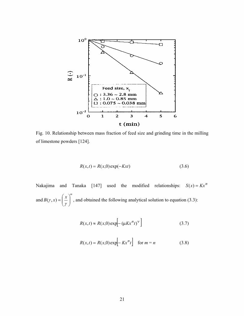
milling process of many materials [124-126]. Kotake et al [124] studied the milling of
limestone powders, and used the first order equation to describe the relationship between
the mass fraction of feed size and grinding time, as shown in Fig. 10.
3.4 Higher order equations
In higher order equations (3.1), (3.2) and (3.3), the selection function S and the breakage
function B are dependent on the process parameters. Different solutions of the selection
and breakage functions have been obtained, and were used in different processes. Reid
[145] gave an analytical solution to equation (3.3) using the relationships: KxxS =)(
and γγ /),( xxB = :
21
Fig. 10. Relationship between mass fraction of feed size and grinding time in the milling
of limestone powders [124].
)exp()0,(),( KxtxRtxR −= (3.6)
Nakajima and Tanaka [147] used the modified relationships: nKxxS =)(
andm
xxB
=
γγ ),( , and obtained the following analytical solution to equation (3.3):
[ ]νµ−≈ )(exp)0,(),( tKxxRtxR n (3.7)
[ ]tKxxRtxR n−= exp)0,(),( for m = n (3.8)

22
Fig. 11. Relationship between normalized oversize and particle size in the milling of
alumina [127].
where m is constant in the breakage function, and γ is the particle size to be broken (µm);
K is breakage rate constant (µm-nhr-1); n is constant in the selection function. x is particle
size (µm).
In equations (3.7) and (3.8), R(x, 0) is the initial oversize distribution function, and R(x, t)
is the oversize distribution function of particles after grinding a certain time t. µ and ν are
constants. µ and ν can be determined by m/n. Equation (3.7) can be rewritten to the
following expression:
)ln()ln()0,(),(lnln xnKt
xRtxR νµν +=
− (3.9)
This relationship has been used to describe the grinding process of alumina, and the result
is presented in Fig. 11 [127]. Kapur and Agrawal [148] gave another simple solution to
the batch grinding equation (3.2):
23
+=
!2exp)0,(),(
2)2()1( tKtKxRtxR (3.10)
If only the first term is considered, K(1) can be expressed as follows [129, 130]:
( )tKxRtxR )1(exp)0,(),( = (3.11)
[ ]AxxkxK
)/(1 *)1(
+=
α
(3.12)
The values of the parameters, k, α, A and x* can be obtained from the grinding
experiment. The following equation can be used to express the grinding kinetics:
[ ]
+= t
xxkx
xRtxR Ai
i*/1
exp)0,(),(α
(3.13)
Equation (3.13) is also called single Kapur function. As a special case, the breakage and
selection functions can be expressed by the constant K(1) [129, 130]:
)1(
ii KS −= (3.14)
and
)1(
)1(
j
iij K
KB = (3.15)
or
j
ii
j
iiij S
SSK
KKB
−=
−= −− 1
)1(
)1()1(1 (3.16)
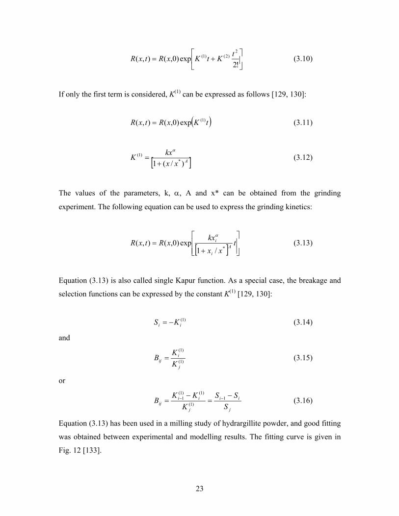
Equation (3.13) has been used in a milling study of hydrargillite powder, and good fitting
was obtained between experimental and modelling results. The fitting curve is given in
Fig. 12 [133].
24
Fig. 12. Fit of batch grinding curves by a single Kapur function in the milling of
hydrargillite [133].
Based on the cumulative distribution from equation (3.2), an approximate solution [144]
was also derived:
2)0(
)(ln
2tHtGR
tR ii
i
i += (3.17)
pH
GR
pRp
ii
i
i
2)0()(
ln1+= (3.18)
Equations (3.17) and (3.18) are also called G-H solutions for the batch grinding equation,
and the straight lines on the plots of )0()(
ln1
i
i
RpR
p ~ p are called G-H plots, where Gi is the
intercept of the G-H plot for the ith size interval, Hi twice the slope of the G-H plot for
the ith size interval, p is number of passes through the grinding chamber, and Ri(p) is
cumulative weight fraction of the ith size interval retained after p passes.

25
Rajendran Nair studied the effect of the operating variables of a circular fluid energy mill
on the breakage parameter using calcite powder [131]. A G-H plot versus the number of
passes was obtained for different particle sizes, as shown in Fig. 13.
Fig. 13. G-H plot in the milling of calcite [131].
26
4. Swelling of Fe-Cu alloy sintered at the temperatures
above Cu melting point
4.1 Variation of swelling with copper content
One of the most attractive powder metallurgy materials is sintered Fe-Cu alloy. Copper
sintered alloys show better properties than pure sintered iron. Solution hardening and
precipitation hardening lead to higher mechanical properties in this sintered steel, and
liquid phase sintering and transient liquid phase sintering make the homogeneity of the
elements much faster. The main disadvantage of this sintered alloy is that copper liquid
causes swelling of Fe-Cu compact made from an elemental powder mixture when the
sintering temperature is above the copper melting point.
In the past 50 years, many investigations on swelling of sintered Fe-Cu alloys have been
made. Two expansion mechanisms have been suggested, diffusion and penetration.
Bockstiegel [34] reviewed the studies before 1962, which included the effects of copper
content, carbon, prealloyed powder, and oxides. Several authors [35, 149, 150] suggested
that the volume expansion is caused by the diffusion of copper into iron. Krantz [151]
pointed out that both grain boundary penetration and lattice diffusion contribute to
volume expansion, and that grain boundary penetration is more rapid than lattice
diffusion. Trudel et al [152, 153] reported that copper penetration into the grain
boundaries of pure iron was important for the swelling in their study on Fe-Cu-C
compacts made from elemental powders containing from 2.4 to 12.8%Cu and 1%C.
Lenel et al [36] also suggested that the swelling resulted from the liquid penetration of
copper along the grain boundaries but both between and within iron particles. Berner et al
[37] examined the diffusion mechanism by using spool-model experiments to determine
the diffusion coefficient. These authors showed that diffusion is too slow to contribute to
the swelling, and the swelling is caused by the penetration of liquid copper into some
favourably oriented iron grain boundaries. Other authors, Dautzenberg, [38] Jamil et al
[39] and Magee [40] also confirmed that the penetration of liquid copper is the main
cause of the expansion in this system. Kaysser et al [154] and Tabeshfar et al [155] have

27
Fig. 14 Dilatometry of Fe-Cu sintered alloy [38].
made a quantitative analysis of the swelling in Fe-10%Cu alloy. Kaysser et al divided the
expansion process into four steps. The first two steps are the penetration of copper into
the areas between iron particles, and along grain boundaries, which is followed by the
diffusion of Cu into Fe particle contact areas, and into disintegrated Fe grains. It was
suggested that 60% of swelling comes from the penetration of copper liquid, and 40%
from the diffusion Cu into Fe. Tabeshfar et al [155] found that when Cu diffuses into Fe
grains, the volume increase is only 1%. Fredriksson et al [156] studied the penetration
rate of liquid copper into iron grain boundaries. In their model, the driving force for
penetration of liquid copper into the iron grain boundaries is the condensation of
vacancies and the surface/interface free energy change.
The dimensional change of different Fe-Cu alloys when liquid copper is present was
studied using dilatometer technique [34, 150, 153, 157-160], as shown in Fig. 14 [38].
The dimensional change rapidly increases when copper content is less than a certain
value, and more slowly above this value. This value is dependent on the solubility limit
of copper in γ-iron at the sintering temperature (~ 8wt-% at 1150°C) [160]. When copper

28
content is less than this solubility limit, solid state sintering takes place after the
expansion process. Above this solubility, sintering is controlled by a liquid phase
sintering mechanism [161-164], i.e. the shrinkage results from the liquid phase sintering,
which compensates part of the expansion. However, Lawcock and Davies [160] reported
that the maximum growth at 8wt-%Cu is due to the boundary coverage driving force
rather than an excess liquid phase sintering mechanism.
4.2 Effect of carbon on the swelling
Carbon is a useful element in Fe-Cu sintered alloys. Carbon does not only improve the
mechanical properties but also decreases the swelling caused by copper during sintering.
Numerous investigations on the effect of carbon on expansion of Fe-Cu sintered alloy
have been reported [34, 35, 37, 40, 150-153, 157-160, 165]. Expansion of Fe-Cu
compacts is greatly reduced by carbon addition, as shown in Fig. 15 [38].
Fig. 15 Dilatometry of Fe-5%Cu-C sintered steels [38].

29
Trudel et al [152] compared the diffusion of copper into pure iron and iron-copper-carbon
steel, and stated that liquid copper penetrates into the grain boundaries of pure iron, but
does not penetrate Fe-Cu-C steel. They further suggested that carbon reduces the grain
boundary energy of iron, thus causing an increase in the dihedral angles at grain
boundaries, which are in contact with the copper-rich liquid phase. Krantz [151] proposed
that carbon reduces the expansion caused by liquid copper since carbon prevents the
penetration of copper into the iron grain boundaries due to increases of the dihedral angle.
The dihedral angle has been measured in several studies and it has been confirmed that in
Fe-Cu-C alloys, the dihedral angle increases with increasing carbon content [37, 40, 160].
Dilatometric measurements in Fe-Cu-C compacts have shown that the expansion caused
by liquid copper at the copper melting point can be completely inhibited when 1.0%
carbon is added in Fe-Cu-C compacts [153, 156, 157, 162].
Different iron powders were used to study expansion of Fe-Cu compacts [36, 40, 155,
165-167]. Lenel et al [36] used three iron powders with different specific surface areas to
study Fe-3%Cu alloy. It was found that the compacts made from iron powder with higher
specific surface area do not grow during sintering above the copper melting point, while
expansion occurred in the compacts with lower specific surface area. Higher surface area
iron powder in the compacts, larger expansion was obtained. They suggested that in the
compacts which do not grow during sintering, the liquid copper penetrates along the
walls of the interior pores within iron particles, while in the compacts which show growth
during sintering, the liquid copper penetrates along the grain boundaries both between
and within the iron particles. Similar results for Fe-10%Cu alloy were reported by
Tabeshfar [40], Jamil and Chadwick [155]. They found that the amount of growth is
dependent on the microporosity in the iron grains. Griffo et al [165] used different
atomized and reduced powder, and reported that the atomized powder compact exhibits
swelling, while the reduced powder compact shows shrinkage. They suggested that the
densification in the compacts made from the reduced iron powder takes place at lower
temperature. In another paper, Griffo et al [166] mixed two iron powders with different
specific surface areas in Fe-2%Cu-0.8%C compacts, and stated that the swelling can be
reduced by increasing the surface area of the iron mixture.

30
4.3 Effect of porosity, particle size, prealloyed powder and alloying additives
The particle size of copper powder also affects the expansion of Fe-Cu compacts.
Danninger [168] reported that in Fe-3%Cu alloys compacted at different pressures, the
compacts with larger copper particles showed larger dimensional change. Griffo et al
[169] studied the effect of the particle size ratio of iron to copper (Fe/Cu) on swelling in
Fe- 2%Cu-0.8%C compacts. The results showed that the growth is reduced with a larger
particle size ratio of iron to copper, and the larger particle size ratio of iron to copper
produces a larger swelling during heating but smaller final dimensional change. Griffo et
al [165] also reported that larger copper particles lead to less volume growth after cooling
to room temperature in Fe-2%Cu-0.8%C compact using atomized iron powder.
The effect of iron particle size on swelling of Fe-Cu compacts was also reported [34, 37,
150, 170]. Bockstiegel [34, 150] found that the volume change of Fe-Cu compacts
increases with increasing iron particle size, thereafter the swelling decreases when the
iron particle size is larger than a certain value. No swelling occurred in the compacts with
green density of 5300 kg/m3 when the iron particle size is less than 7 µm, as shown in Fig.
16 [34].
In Berner’s study [34], a maximum amount of swelling was observed at a medium
particle size of iron. It was suggested that in the compacts with fine iron powder, initial
swelling is compensated by shrinkage from liquid phase sintering, and in the compacts
with coarse iron powder, there is a smaller number of particle contacts and grain
boundaries per unit volume. Masuhara et al [170] found that the compacts with finer iron
particles show more shrinkage.
Bockstiegel [34, 150] reported that compacts with lower green densities at the same
copper content demonstrate lower volume swelling, and in compacts containing less than
8%Cu, the difference of volume growth is very small. A big difference was obtained in
compacts containing higher than 8%Cu. Krantz [151] showed similar results, but at low
copper contents (less than 5%) the same swelling was obtained in the compacts with
relative densities of 70-72% and 77-84%, as shown in Fig. 17 [151].
High contents compacts with 70-72% relative density showed low swelling. Jamil,
Tabeshfar, Chadwick [40, 155] studied the effect of the compacting pressure between

31
Fig. 16 Effect of particle size of iron powder on volume changes during sintering of fe-
Cu compacts at 1150°C for 60 min [34].
Fig. 17 Dimensional change versus copper content of Fe-Cu sintered alloys [151].

32
140 MPa and 770 MPa on the volume change of Fe-10%Cu and Fe-10%Cu-1%C
compacts. They found that in the specimens made from atomized iron powder (low
specific surface area) volume swelling does not change with the compacting pressure.
The swelling of Fe-Cu compacts was studied using prealloyed powder as a base powder
as well as additive powder [34, 38, 152, 156, 171]. It was found that when iron and
copper prealloyed powder was used as base powder, swelling of the compacts during
sintering above the copper melting point was not observed [38, 152, 156, 171]. In the
compacts containing less than 8%Cu, swelling does not occur because no copper liquid is
formed during sintering. When the copper content is larger than 8%, liquid copper
penetrates in smaller amounts and more slowly in grain boundaries than in pure iron. The
effects of tungsten metal, prealloyed powder, and oxides on swelling of Fe-Cu compact
were reported [34, 35, 149]. When W powder was added to a Fe-7.5%Cu compact, the
dimensional growth decreased. This amount of reduction increases with increasing
heating rate [34]. W content larger than 0.8% in Fe-Cu alloys can completely suppress the
swelling by liquid copper when a heating rate of 200°C/min was used. Similar results
were obtained when WO3 or MoO3 were added to Fe-7.5%Cu compacts, as shown in Fig.
18 [34].
Fig. 18. Influence of additions of tungsten, tungsten oxide, molybdenum oxide, carbon
and phosphorus on the dimensional change of Fe-7.5%Cu compact sintered at 1150°C for
60 min at a heating rate of 50°C/min [34].

33
The reduction of dimensional growth in Fe-Cu-WO3 compacts is larger than that in Fe-
Cu-C compacts if the same amount of WO3 as carbon was used. Another interesting
finding is that when prealloyed tungsten-iron powder was used, the swelling in Fe-
7.5%Cu compacts does not change or decrease to a very small amount. The effect of
tungsten on the swelling is shown in Fig. 19 [34], and the swelling for the compacts used
prealloyed Fe-W powder is shown in Fig. 20 [34].
Fig. 19. Influence of W on the swelling of Fe-Cu alloy sintered at 1150°C for 60 min at a
heating rate of 200°C/min [34].
Fig. 20. Influence of the heating rate and prealloying degree between Fe and W on the
dimensional change of Fe-7.5%Cu compacts sintered at 1150°C for 60 min [34].
34
Magee and Lund [39] suggested that tungsten at surfaces probably prevented diffusion of
copper into iron, and also retarded solution-precipitation processes. Nickel metal and Cu-
P prealloyed powder can inhibit the swelling in Fe-Cu compacts. When a certain amount
of CuO, Cu-30%Mn, Cu-30%Ni, Cu-70%Ni, or Cu-30%Pb powders (amount less than
7.5%) was added to Fe-Cu alloys, the swelling during sintering can be reduced to
different extents.

35
5. Sintered steels with copper, manganese, molybdenum
and silicon elements
5.1 Liquid phase sintering of powder metallurgy steels
The sintering of binary and multi-component alloy can be divided into solid state
sintering and liquid phase sintering [1]. Solid state sintering is a process during which the
compacts are sintered at temperatures below the melting points of the components, and
the densification of the compact is controlled by solid diffusion. Liquid phase sintering
occurs at a temperature where a liquid and solid coexist due to chemical reaction, partial
melting, or eutectic liquid formation [1]. Liquid phase sintering is an important sintering
mechanism and densification method in many materials [172-181]. The mobility of the
atoms in the liquid phase is much higher than that in the solid state. The characteristics of
liquid phase sintering are low sintering temperature, quick densification, good
homogenization, high sintered density, improved mechanical and physical properties.
Hence, liquid phase sintering can accelerate the sintering process, give higher density,
and improve the mechanical properties. Conventional liquid phase sintering is also called
persistent liquid phase sintering, which has been studied in many systems [182-186] such
as metal alloy [174, 175, 181-183, 185], ceramics [172], heavy alloys [172, 176, 177],
cermets [178], cemented carbides [51-53] and composite [179, 180, 184]. There are three
stages in the persistent liquid phase sintering process [187], which were also discussed in
the other studies [174, 188]:
• Rearrangement: melt flow and penetration repacking, rapid densification or swelling,
particle sliding;
• Solution-reprecipitation: diffusion controlled densification, shape accommodation,
grain growth, neck formation;
• Solid state: rigid structure neck growth, grain growth, coalescence, and pore
coarsening.
36
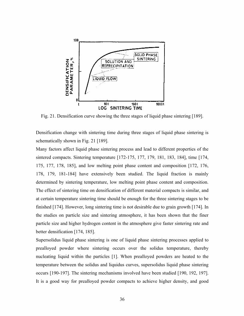
Fig. 21. Densification curve showing the three stages of liquid phase sintering [189].
Densification change with sintering time during three stages of liquid phase sintering is
schematically shown in Fig. 21 [189].
Many factors affect liquid phase sintering process and lead to different properties of the
sintered compacts. Sintering temperature [172-175, 177, 179, 181, 183, 184], time [174,
175, 177, 178, 185], and low melting point phase content and composition [172, 176,
178, 179, 181-184] have extensively been studied. The liquid fraction is mainly
determined by sintering temperature, low melting point phase content and composition.
The effect of sintering time on densification of different material compacts is similar, and
at certain temperature sintering time should be enough for the three sintering stages to be
finished [174]. However, long sintering time is not desirable due to grain growth [174]. In
the studies on particle size and sintering atmosphere, it has been shown that the finer
particle size and higher hydrogen content in the atmosphere give faster sintering rate and
better densification [174, 185].
Supersolidus liquid phase sintering is one of liquid phase sintering processes applied to
prealloyed powder where sintering occurs over the solidus temperature, thereby
nucleating liquid within the particles [1]. When prealloyed powders are heated to the
temperature between the solidus and liquidus curves, supersolidus liquid phase sintering
occurs [190-197]. The sintering mechanisms involved have been studied [190, 192, 197].
It is a good way for prealloyed powder compacts to achieve higher density, and good

37
mechanical properties. Sintering temperature is the most important parameter in
supersolidus sintered materials. Only a narrow processing window is available in such
materials, which gives good densification without distortion. A schematic sintering curve
of supersolidus liquid phase sintering is shown in Fig. 22 [195]. Three temperatures were
identified, initial sintering temperature, minimum temperature for full density, and
distortion temperature [194]. The temperatures vary with the material type and
composition [190, 193-196]. The sintered density change for prealloyed Ni-Si-B powder
is presented in Fig. 23 [190].
Transient liquid phase sintering is defined as a sintering cycle characterized by the
formation and disappearance of a liquid phase during heating, and the initial compact has
at least two differing chemistries and the first liquid must be soluble in the remaining
solid [1]. Transient liquid phase sintering in different systems has been reported [198-
206]. Modeling, homogenization, and pore formation during transient liquid phase
sintering were studied [202, 203]. The occurrence of persistent liquid phase sintering or
transient liquid phase sintering is dependent on the phase diagram of the alloy system or
Fig. 22. Schematic sintering curve of supersolidus liquid phase sintering [195].

38
Fig. 23. Sintered density versus temperature for prealloyed Ni-Si-B powder [190].
mutual solubility of the elements [202, 203]. In transient liquid phase sintering, the liquid
phase is completely soluble in the solid component, and liquid phase only exists in the
initial stage of sintering. Densification mainly relies on solid state sintering. If not enough
amount of liquid phase is present, the secondary pores are formed in the transient liquid
phase sintered compacts [202]. The formation and disappearance of liquid phase is
determined by the distribution of the lower melting point component [201]. A difference
between transient liquid phase sintering and supersolidus, persistent liquid phase sintering
is that heat rate influences the homogenization, densification and properties of the
sintered materials by changing liquid phase formation and amount due to interdiffusion
[200], as shown in Fig. 24. Transient liquid phase sintering is the most important
sintering mechanism in the sintered steels because most of the elements used have high
solubility in iron. The liquid for enhanced sintering should ideally have the following
characteristics when iron is used as a base alloy [200]:
• Has a low vapour pressure;
• Approximate 10 to 15 volume percent liquid at the sintering temperature;
• Wet iron powder;

39
• Small interval between liquidus and solidus;
• Provide for rapid diffusion of iron;
• Have a high solubility for iron;
• Be soluble in iron.
Fig. 24. A schematic diagram showing the events during transient liquid phase sintering.
The upper drawing shows the homogeneity of the compact versus the process cycle,
which includes heating followed by an isothermal hold. Two different heating rates are
shown and the vertical lines indicate the eutectic temperature and sintering temperature.
The centre drawing shows the amount of liquid for these heating rates. The lower
drawing gives an example of the dimensional changes associated with these two heating
rates.

40
5.2 Master alloy techniques used in powder metallurgy steels
Master alloy technique has been used for producing different kinds of materials [207-
210]. Master alloy powder is a prealloyed powder of high concentration of alloy content,
designed to be diluted when mixed with a base powder to produce the desired
composition, and prealloyed powder is defined as a metallic powder composed of two or
more elements that are alloyed in the powder manufacturing process and in which the
particles are of the same nominal composition throughout [2].
Intermetallic compounds have also been used as master alloy in powder metallurgy steels.
Fe-B, Fe-P intermetallics, and Cu3P alloy are good examples to achieve high density
sintered steels through liquid phase sintering [181, 211, 212]. Ferromanganese,
ferrosilicon and Cu-35%Mn alloys were used for adding manganese to sintered steels
[31-33, 213, 214]. Danningar [202] suggested that an intermetallic phase is a suitable
composition for master alloy, as shown in Fig. 25, and described homogenization and
densification process.
Fig. 25. Binary system with intermetallic phase (AB); suitable composition of master
alloy [202].

41
Fischmeister et al [215] developed a master alloy with a composition of 50%Mn-50%Cu
and melting point in the range between 890 and 940°C, and added it to iron powder. A
series of Mn-Ni-Cr-Mo-Fe and Mn-Cu-Ni master alloys was studied [29]. Addition of
elements to the base powders in the form of master alloy results in faster densification
and better homogenization than for the elemental powders.
It is possible to introduce elements having high affinity to oxygen in sintered steels using
master alloy technique. Successfully used master alloy powders are Fe-20%Mn-20%Cr-
20%Mo-7%C and Fe-20%Mn-20%V-20%Mo-7%C [26-28, 216]. Carbides of chromium,
tungsten and vanadium master alloys were also studied [217]. Those master alloys
showed transient liquid phase sintering, which enhances the homogenization process.
Carbides are an important form to be used as master alloy in the sintered steels because
their low melting point and transient liquid phase sintering. The melting point of some
carbides used in the iron base sintered alloys are summarized in Table III [28].
Table III Liquid phase formation in some iron-base alloys [28]
System Reaction components Melting temperature (°C) Fe-Cr-C L+Cr7C3=γ+Fe3C
Peritectic ~1184
Fe-Mo-C Fe3C+γ+Mo2C+L ~1080 Fe-Mo-C Fe3C+γC+Mo2C+L ~1120 Fe-Mo-C γ+Mo2C+η+L
α+γ+η+L ~1150 ~1210
Fe-Mn-C L+γ+(Fe, Mn)3C (20 wt%Mn, 4.2 wt%C)
1080
Fe-Cr-Mo-C 5-6 at%Mo+Cr 8 at%Mo+Cr 20 at%Mo+Cr
with 15 at%C (~3.6 at%C)
1160 1120 1160
Ferromanganese, ferrosilicon and Fe-Mn-Si master alloy were added to iron powders [31-
33]. The sintered steels with ternary Fe-Mn-Si master alloy showed higher mechanical
properties and more uniform microstructure than those with ferromanganese and
ferrosilicon master alloys, and good dimensional stability was obtained for Fe-Mn-Si
master alloy steels, as shown in Fig. 26 [32].

42
Fig. 26. Dimensional change during sintering of compacts from Fe, Fe-Mn, Fe-Si and Fe-
Mn-Si powders [32].
5.3 Properties of copper, manganese, molybdenum and silicon sintered steels
Hanningar [168] studied Fe-3%Cu compact pressed at 1120 MPa pressure and sintered at
1250°C, and got an ultimate tensile strength of 450 MPa and an elongation of 13%. When
carbon is added to Fe-Cu alloy, the strength has been much improved. An ultimate tensile
strength of 530 MPa with an elongation of 2.5% could be obtained in Fe-10%Cu-1%C
alloy sintered at 1150°C for 60 min in argon [218]. In Fe-6%Cu-(0.1-1.1)%C sintered
steels, increasing carbon content resulted in increment of transverse rupture strength, and
a linear relationship between transverse rupture strength and sintered density was
obtained [151].
Trudel et al [152, 153] studied the effect of copper content on ultimate tensile strength
and elongation of Fe-Cu-C prealloyed compacts sintered at 1120°C for 30 min, and the
properties of sintered prealloyed compacts were compared with those of sintered
compacts made from elemental powder mixture. Fe-Cu sintered compacts made from
elemental powder mixture showed higher ultimate tensile strength and elongation than

43
those made from prealloyed powder when copper content was less than 5%, and when
copper content was larger than this value, the prealloyed powder compacts showed higher
properties. When the addition of 0.75-0.95%C, this copper content shifted to 8%.
Fe-Mo, Fe-Mo-P and Fe-Mo-C sintered steels have been studied [219-224]. Youseffi et al
[219] studied prealloyed Fe-1.5%Mo alloy sintered at 1140°C for 60 min in vacuum, and
obtained an ultimate tensile strength of 150 MPa and a hardness of 105 HV10. When
carbon was added to this alloy powder improved properties were achieved, for example, a
tensile strength of 580 MPa and a hardness of 195 HV10 for Fe-1.5%Mo-0.8%C alloy.
Increasing sintering temperature can also improve the mechanical properties. A tensile
strength of 710 MPa could be obtained for Fe-1.5%Mo-0.8%C alloy sintered at 1250°C
for 60 min. For Fe-4%Mo-0.6%P alloy sintered at 1120°C for 45 min in exogas, an
ultimate tensile strength of 400 MPa with a hardness of 160 HV5 and an elongation of
8% could be reached [221]. When higher sintering temperature and hydrogen were used,
the mechanical properties were improved [222]. Danningar [224] studied Fe-1.5%Mo-
0.7%C steel compacted at a pressure of 600 MPa and sintered at 1280°C for 60 min, and
obtained a tensile strength of 740 MPa, and an elongation of 3.6%. Cambronero et al
[223] also studied Fe-1.5%Mo-0.7%C steels using elemental molybdenum powder and
prealloyed Fe-1.5%Mo powder sintered at 1160°C for 60 min in hydrogen, and better
mechanical properties were obtained for the compacts with prealloyed powder, as well as
after heat treatment. The ultimate tensile strength and hardness of these sintered steels are
shown in Fig. 27.
The properties of sintered compacts made from prealloyed powders containing copper,
nickel and molybdenum were reported [22-25, 225, 226]. An ultimate tensile strength of
790 MPa with a hardness of 289 HV10 and an elongation of 4% could be obtained in Fe-
1.48%Cu-1.74%Ni-0.56%Mo-0.5%C alloy sintered at 1150°C for 60 min [225]. Ultimate
tensile strength of this alloy after heat treatment could reach 1200 MPa with a hardness of
500 HV10. An ultimate tensile strength of 627 MPa with hardness of 179 HV10 and an
elongation of 2.5% was obtained for Fe-1.5%Mo-2%Cu-0.4%C steel [227].
Cias et al [228] studied Fe-(2-4)%Mn-(0.6-0.8)%C alloys sintered in the temperature
range of 1120-1300°C, and achieved tensile strength of 300-600 MPa and a yield

44
Fig. 27. Properties of molybdenum steels as function of graphite addition, heat treatment
and type of powders used [223].
strength of 275-500 MPa. Youseffi et al [30] studied Fe-3%Mn-1.5%Mo-0.6%C steel
using Astaloy 1.5Mo and ferromanganese powders, and obtained a tensile strength of 530
MPa. It was indicated that when Mn was added to Mo sintered steels, both tensile and
bend rupture strengths increased, and the sintered microstructures were cooling rate
dependent.
Both MCM (Fe-20%Mo-20%Cr-20%Mn-7%C) and MVM (Fe-20%Mo-20%V-20%Mn-
7%C) sintered steels were investigated. A tensile strength of around 700 MPa was
obtained in the steels with 2% master alloys corresponding to a composition of Fe-
0.4%Mo-0.4%Cr-0.4%Mn after double sintering. The tensile strength could reach 1120

45
MPa by sintering and heat treatment, and 1900 MPa by sintering, heat treatment and
forging [26]. Mn-Mo sintered steels were studied using MM (Fe-20%Mo-40%Mn-7%C)
master alloy, and a tensile strength of 560 MPa was obtained in the sintered steel with 2%
MM, and the properties after heat treatment and forging are competitive with those of
MCM sintered steels [26].
Another Fe-Mn-Si master alloy steel with a composition of Fe-3.2%Mn-1.4%Si-0.4%C
[31] showed an ultimate tensile strength of 920 MPa with a hardness of 300 HV20 and an
elongation of 2.0%. The mechanical properties of Fe-Mn-Si master alloy sintered steels
are presented in Fig. 28 [31].
Fig. 28. Mechanical properties of Mn-Si-C steels with a ternary Fe-Mn-Si master alloy
addition sinterd at 1180°C for 60 min [31].

46
6. Summary of included papers
6.1 Nanostructured W-Co and WC-Co powders (Paper I, II and III)
The production of nanostructured tungsten carbide from chemical precursors involves
several steps: synthesis, (calcinations), reduction, and carburization. In this part of the
present thesis, calcination of the precursor and formation of nanostructured W-Co and
WC-Co powders by reduction and carburisation processes have been studied. The
precursors, which contain a varying composition of W and Co, were prepared by a water
mediated reaction between ammonia paratungstate (APT) and cobalt hydrate (Co(OH)2).
Both salts are slightly soluble and were suspended in a stirred reactor containing water.
The reaction mixture was heated to 90°C for 3 hours. The amount of APT and Co(OH)2
salts used was varied for each experiment. After the reaction was completed, the solid
powder formed was filtered off, washed, and dried in air at 105°C. Four precursors, with
W/Co ratio of 2.0, 2.8, 4.7 and 9.0, were synthesized and denoted as W20, W28, W47,
and W90 respectively.
6.1.1 Calcination (Paper I)
The precursor with W/Co ratio of 4.7 was calcined at different temperatures under non-
flowing air, flowing air, or flowing nitrogen for 5 hours, and the properties of the
products at different temperatures and decomposition have been studied. In general, the
decomposition of the precursor under gas phases can be divided into five main parts. The
decomposition of the precursor under different gas phase conditions gives various
decomposition reactions. The reactions occurring at each stage in air, nitrogen and
helium-5%oxygen have been evaluated according to X-ray diffraction (XRD),
temperature programmed decomposition reactor (TPR), thermogravimetric analysis
(TGA) and differential thermogravimetric analysis (DTGA) results. TGA and DTGA
curves in flowing air are presented in Fig. 29. In five steps, different amounts of water
and ammonia were released, and different weight losses were obtained. By calcining the
sample at temperatures lower than 520°C, the precursor completely decomposes into

47
200 400 600 800
DTGA
TGA95
90
85
Wei
ght c
hang
e (%
)
d
m/d
t
Temperature (oC)
Fig. 29. DTA and DTGA curves of the precursor.
oxides (main composition CoWO4 and WO3)with a total weight loss of 10.3%. The
decomposition process of precursor W47 proceeds through five steps occurring in
different temperature ranges, which are also atmosphere dependent.
Two transformations occurred during the calcination process: a crystalline phase
transformed into an amorphous phase, and the amorphous phase transformed into a
crystalline phase again. The results showed that two maximum specific surface areas
were obtained at these phase transformations. The XRD spectra of the powders calcined
at different temperatures in flowing air are presented in Fig. 30. The powders calcined at
low temperatures were mainly amorphous under all atmospheres, while those calcined at
high temperatures were crystalline. However, the amounts of the phases vary with
temperature and the calcination atmospheres. For instance, the powders obtained under
flowing air were mainly amorphous with a small fraction of
(NH4)xCo2.5H2W12O39.5+0.5x•yH2O up to 320°C. A larger fraction of
(NH4)xCo2.5H2W12O39.5+0.5x•yH2O and (NH4)0.33WO3 formed at 320°C under flowing
nitrogen, while the amorphous phase completely disappeared in the powder calcined
under non-flowing air at the same temperature.

48
10 20 30 40 50 60 70 80Two theta (degree)
220 C
320 C
270 C
450 C
400 C
350 C
550 C
500 C
650 C
aa
aa
b
bbb
c
c
cc
bb
bb
b
d
d
c
ccc
ccc
d
d
d d
b
dc
c
c c c
d
d
d
ccc
c
e
ddd d dd
dd
d
d
ddd
d
a-(NH4)xCo2.5H2W12O39.5+0.5x·yH2O b-(NH4)0.33WO3, c-CoWO4, d-WO3
b ba
cba
Fig. 30. XRD spectra of the powders calcined at different temperatures under flowing air.
The specific surface area of the calcined powders also varied with the calcination
temperature and atmosphere. The change in the specific surface area is expected to result
from the decomposition as well as the phase transformation of the materials under the
calcination conditions. An increase in the specific surface area was observed as the
material decomposed by evaluation and formation of other solid phases. The specific
surface area of the calcined powder in flowing air increases with calcination temperature
from ambient temperature (precursor) to 220°C and from 400 to 450°C. However, the
specific surface area decreases from 270 to 350°C and from 500 to 650°C. Two
maximum values, 4640 kg/m2 at 220°C and 9770 kg/m2 at 450°C, were obtained, as
shown in Fig. 31. The powders calcined at medium temperature ranges in the non-
flowing air have higher specific surface area values than those calcined in flowing gases.
6.1.2 Reduction and carburization (Paper II and III)
To study the effect of cobalt on the reduction, precursors W20, W28, W47, and W90
calcined at 220°C in non-flowing air were reduced at 600°C for 1 min and at 650°C for 1,

49
15 and 30 min in hydrogen. In the reduction of the powders with different cobalt contents
calcined at 220°C, the samples with high cobalt content (W28 and W20) are more easily
reduced than those with low content of cobalt. Only sample W90 could not be completely
reduced at 650°C for 30 min. The Co3W phase was observed in sample W20 and W28,
and no W3O was identified in any sample due to low calcination temperatures.
Sample W47 was reduced at 600, 650 and 700°C for 3 or 6 hours in hydrogen. The
powder reduced at 600°C for 3 hours contained a mixture of W and WO2 phases. The
specific surface area of the reduced powders increase with decreasing reduction
temperature (8700 m2/kg at 700°C, 15000m2/kg at 650°C and 18000 m2/kg at 600°C).
The average particle size of the reduced powders, as calculated from the BET-data, was
38 nm at 700°C, 22 nm at 650°C, and 18 nm at 600°C.
The density of the powders with different cobalt content reduced at 650°C was measured
and is shown in Fig. 32. The measured density increased with increasing reduction time.
The density seems to have a maximum value at the composition of W/Co = 4.7. The
density obtained in reduced sample W90 was lower than that in reduced sample W47,
because sample W90 was not completely reduced. Cobalt accelerates the reduction rate,
and the agglomeration of the powder with high cobalt content takes place in shorter time
0 100 200 300 400 500 600 7000
2000
4000
6000
8000
10000
Precursor
Surfa
ce A
rea
(m2 /k
g)
Temperature (0C)
Fig. 31. Specific surface area of calcined powder under flowing air.

50
than powders with low cobalt content. The specific surface areas of reduced samples
W90, W47, and W28 at 650°C increased with increasing reduction time for 1 min to 15
min, then decreased from 15 min to 30 min, as shown in Fig. 33.
Fig. 32. Measured density vs. ratio of W to Co. Inset shows reduction fraction change of
W/Co=4.7 and 9.0 powders with the reduction time at 650°C
Fig. 33. Surface area vs. ratio of W to Co. Inset shows particle size change with the
reduction time in W/Co=2 completely reduced powder at 650°C.
12000
13000
14000
15000
16000
17000
18000
19000
2 3 4 5 6 7 8 9 10W/Co
Den
sity
(kg/
m3 )
1 min 15 min30 min
60
70
80
90
100
0 10 20 30Reduction time (min)
Red
uctio
n fr
actio
n (%
) W/Co=4.7
W/Co=9.
6000
8000
10000
12000
14000
16000
2 3 4 5 6 7 8 9 10
W/Co
Surf
ace
area
(m2 /k
g)
1 min 15 min30 min
35
40
45
50
55
0 10 20 30 40Reduction time (min)
Parti
cle
size
(nm
)

51
A precursor of W/Co = 4.7, after reduction at 700°C for 3 hours, was carburized at 700°C
for 3 hours in different mixtures of CO and CO2. The phase constituents vary with the
CO/CO2 ratio in the gas. A mixture of W, W2C, W6Co6C and W3Co3C was obtained, and
no WC was observed in the powder carburized in 70%CO/30%CO2 gas. Increasing the
concentration of CO up to 80% only W2C and W3Co3C phases formed in the powder. A
full conversion to WC was obtained using 90%CO/10%CO2 atmosphere. The increase in
the amount of bound carbon with increasing CO/CO2 ratios suggests a reaction path
starting with metallic W-Co particles and ending with a WC mixture:
W-Co → W6Co6C → W3Co3C → W2C-Co → WC-Co
The specific surface area (8.1 m2/g) of the final WC-Co powder corresponding to a
particle size of about 50 nm has been obtained. The micrigraphs of the precursor, reduced
and carburised powders are shown in Fig. 34.
Fig. 34. Micrographs of precursor W20 (a) and reduced W20 powder at 650°C for 30 min
(b), precursor W47 (c) and carburised W47 powder at 700°C for 3 hours in
90%CO/10%CO2 after reduction at 650°C for 3 hours (d).
1 µm
a b
c d

52
6.2 Sintered steels (Paper IV, V, VI and VII)
6.2.1 Grinding kinetics study of Fe-Mn-Si powders (Paper IV)
Four Fe-Mn-Si master alloy powders with the compositions of Fe-35%Mn-14%Si, Fe-
35%Mn-20%Si, Fe-45%Mn-20%Si, and Fe-60%Mn-14%Si were produced by casting
and ball milling, and denoted M1, M2, M3 and M4. The master alloy powders mainly
containing (Fe, Mn)3Si and (Fe, Mn)5Si3 were milled for 10 min to 120 min. Particle size
distribution and milling kinetics of Fe-Mn-Si powders were studied, and the parameters
in the breakage function have been determined.
The milled powder characteristics vary with milling time, and the contents of silicon and
manganese. During milling, the particle size of the original powder significantly
decreases after milling. At longer milling times, however, small particles agglomerate to
larger particles. The particle distribution of the M1 powders milled for different times is
shown in Fig. 35. The optimum milling time of the Fe-Mn-Si master alloy powders seems
to be around 60 min. The mean particle size of the powders varies between 5 µm and 15
µm and depends on the compositions of Fe-Mn-Si master alloys.
0
10
20
30
40
50
60
70
80
90
100
0 20 40 60 80 100 120 140 160
Particle size (micron)
Cum
ulat
ive
unde
rsiz
e (%
)
Feed powder 10 min 30 min 60 mn 90 min 120 min
Fig. 35. Particle size distributions of the M1 powder milled for different times.

53
20%Si alloys are easier to crush and mill into fine powder compared to the 14%Si alloys.
The effect of silicon content on the particle size distribution of milled Fe-Mn-Si master
alloy powders is much more significant than that of the manganese content. A finer final
particle size can be obtained in the alloy powders with higher silicon compositions.
Milling kinetics of Fe-Mn-Si master alloy powders was also studied by using grinding
equation (3.3). Breakage parameters of the M1 and M3 milled powders have been
obtained according to equation (3.9). From calculated parameters, breakage rate
equations of M1 and M3 powder milling can be expressed as in equations (6.1) and (6.2).
Breakage rate equation for M1 powder milling:
)00024.0exp()0,(),( 39.072.1 txxRtxR −≈ (6.1)
and for M3 powder milling:
)0027.0exp()0,(),( 37.022.1 txxRtxR −≈ (6.2)
It is illustrated that the kinetics of the grinding process of Fe-Mn-Si master alloy powders
can be described by classic batch grinding equation based on the population balance
model until agglomeration of particles sets in. The modelling and experimental results for
M1 powder are shown in Fig. 36. The breakage rate constant, K of the M3 powder is
much higher than that of the M1 powder. It means for the same time the milled M3
powder has much finer particles than the M1 powder.
6.2.2 Swelling of Fe-Cu sintered alloy (Paper V)
A model of swelling of Fe-Cu sintered alloy sintered at temperatures above the copper
melting point has been studied based on the swelling mechanism of the penetration of
liquid copper into iron interparticle boundaries. The model is established based on the
following conditions:
1. Iron and copper powders have about the same particle size, spherical shape, and
uniform deformation during compaction;

54
2. The swelling mechanism of Fe-Cu alloy is mainly due to penetration of Cu liquid
into the boundaries between iron particles;
3. Most of the copper liquid contributes to the swelling except for that consumed by
filling the pores close to copper particles and the pores on the surface of iron
particles as well as that diffusing into the iron
4. The amount of volume growth of compacts is equal to the volume of liquid copper,
which penetrates into iron interparticle boundaries.
In the model, the particle coordination number is introduced to the calculation for
expressing the porosity. The heating rate was used to calculate the thickness of diffusion
layers between iron and copper particles. The volume and dimensional growths of Fe-Cu
compacts with different copper contents at varying conditions can be calculated using
equations (6.3) and (6.4):
[ ]
+
−−
−∗=∆
)1(113104.1
NNVNPV
rdVV Cu
CuCu (6.3)
0
0.2
0.4
0.6
0.8
1
0 20 40 60 80 100 120Milling time (min)
R(x
,t)/R
(x,0
)
3µm Exp5.2µm Exp10µm Exp15µm Exp21µm Exp30µm Exp3.0µm Mod5.2µm Mod10µm Mod15µm Mod21µm Mod30µm Mod
Fig. 36. Comparison of experimental and simulating results in milled M1 powder for
normalized oversize distribution; points are experimental data, and lines are model results
according to equation (6.1).

55
Dimensional growth is then given by:
( ) 1131
−∆+=∆ VL (6.4)
where ∆V is thus at the same time the amount of volume growth of compacts; ∆L is the
relative dimensional change; VCu is the volume fraction of copper; d is the thickness of
Fe-Cu diffusion layer; r is the particle radius; N is powder coordination number; and P is
fractional porosity.
The effect of heating rate on the dimensional swelling at varying copper content for
heating rates, 10, 20 and 60ºC/min using a particle size of 100 µm and 15% porosity
compact has been calculated and is presented in Fig. 37. The calculated results for the
compacts with 5-30% porosities using a particle size of 100 µm and the comparison with
the experimental results [151] are shown in Fig. 38 for a heating rate of 60ºC/min. The
0 0.05 0.1 0.15 0.2 0.250
0.005
0.01
0.015
0.02
0.025
0.03
0.035
0.04
Volume fraction of Cu
Line
ar S
wel
ling
Heating rate12102060mod 10mod 20mod 60
Fig. 37. Comparison of the calculated dimensional swelling with observed data for
compacts with different copper contents and heating rates, and with a particle size of 100
µm and 15% porosity. The legend gives the heating rate in ºC/min, and “mod” is short for
model.

56
Fig. 38. Comparison of the calculated dimensional swelling with observed data from
Krantz [151] for the compacts with different copper contents and porosities, and with a
particle size of 100 µm at a heating rate of 60ºC/min. The experimental values are shown
with markers, the model values with curves.
calculated results have good agreement with the experimental data at low copper content.
At high copper content, the experimental values could be lower the calculated ones
because the swelling and liquid phase sintering occur at the same time, and the shrinkage
from liquid phase sintering has not been taken in account.
6.2.3 Properties of Fe-Mn-Si-C sintered steel (Paper VI)
Fe-45%Mn-20%Si alloy powder was produced using milling, atomizing, and a
combination of atomization and milling methods. Fe-3.2%Mn-1.2%Si-0.35%C steel by
adding Fe-Mn-Si master alloys and graphite has been studied. The specimens with the
milled master alloy were sintered in pure hydrogen at 1100, 1150 and 1200°C for 30, 60
and 90 min and at 1250°C for 30 min. The effects of sintering atmosphere on the
properties of these sintered steels sintered at 1200°C for 90 min were also studied.
0 0.05 0.1 0.15 0.2 0.250
0.01
0.02
0.03
0.04
0.05
0.06
Vo lume fraction o f Cu
Line
ar S
wel
ling
Po rosity0.05 0.10.15 0.20.25 0.30.16-0.230.28-0.30

57
1100 1150 1200 1250250
300
500
600
700
800
900
Hard
ness
(HV2
0), T
ensi
le s
treng
th (M
Pa)
sintering temperature (C)
UTS 30 min HD 30 min UTS 60 min HD 60 min UTS 90 min HD 90 min
Fig. 39. Effect of sintering temperature and time on the tensile strength and hardness of
Fe-Mn-Si-C sintered steel.
The ultimate tensile strength and hardness of the Fe-Mn-Si sintered steels increase
significantly with increasing sintering temperature and sintering time, as shown in Fig. 39.
Elongation and dimensional change variations with sintering temperature and sintering
time are given in Fig. 40. Initially the elongation increases with sintering temperature and
time. The densities of the specimens decrease, i.e. swelling occurred for the steels
sintered at low temperatures and for short times, and densification takes place in the
specimens sintered at the higher temperatures and for the longer times. The highest
sintered density was obtained in an alloy sintered at 1250°C for 30 min. Tensile strength
of the compacts increases significantly with increasing sintering temperature and time
due to the formation of bainite and martensite after cooling, as shown in Fig. 41.
The compacts sintered in hydrogen showed higher ultimate tensile strength, hardness and
elongation than those sintered in argon-5% hydrogen. The compacts with the milled and
atomized-milled master alloys had the same ultimate tensile strength and hardness
sintered both in hydrogen and in argon-5% hydrogen, while those with the atomized

58
1100 1150 1200 1250
-0.4
0.0
0.4
0.8
3.03.54.04.55.05.5
Dim
ensi
onal
cha
nge
(%),
Elon
gatio
n (%
)
Sintering temperature (C)
Elong 30 min Dimen 30 min Elong 60 min Dimen 60 min Elong 90 min Dimen 90 min
Fig. 40. Effect of sintering temperature and time on the elongation and dimensional
change of Fe-Mn-Si-C sintered steel.
Fig. 41 Microstructures of Fe-Mn-Si steels with the milled master alloy sintered at
different temperatures and for different times in hydrogen; (a) 1250°C for 30 min and (b)
1200°C for 90 min.
a b
59
master alloy gave lower ultimate tensile strength and hardness. The same elongation
values have been obtained in the compacts with the three types of master alloys sintered
in hydrogen; the same values were also observed in argon-5% hydrogen. The steels with
the atomized alloy showed lower properties than the steels based on a milled master alloy
due to existence of oxides of manganese and silicon on the surface of atomized Fe-Mn-Si
powders. When the atomized powder is crushed and milled, the oxides on the surface are
broken, and the sintered steels showed the same properties as the sintered steels with the
milled alloy.
6.2.4 Properties of Fe-Mo-Mn-Si-C sintered steel (Paper VII)
Four Fe-Mn-Si master alloy powders were made by the cast-milling method, and used to
produce Fe-Mo-Mn-Si-C sintered steels. The properties of the Fe-Mn-Si master alloys
were given above in section 6.2.1. The M2 alloy steels with varying composition were
sintered at 1250°C for 30 min in hydrogen-30% nitrogen. The four master alloy steels
with 4% content were sintered at 1120°C for 30 min in different atmospheres with
varying dew points.
The steels with the M2 master alloy were sintered at 1250°C for 30 min in hydrogen-30%
nitrogen, and the steels with the four Fe-Mn-Si master alloys were sintered at 1120°C for
30 min in hydrogen and nitrogen-10% hydrogen with different dew points. In transient
liquid phase sintered Fe-Mn-Si master alloy steels, the ultimate tensile strength and
hardness increase and elongation decreases with increasing the contents of the Fe-Mn-Si
alloy and carbon. The tensile strength and hardness versus the manganese content are
shown in Fig. 42. Fe-Mn-Si master alloy and carbon decrease the dimensional shrinkage.
However, The dew point of sintering atmospheres had little effect on the properties of Fe-
Mo-Mn-Si-C sintered steels due to the addition of manganese and silicon in the form of
ternary master alloy. The tensile strength for the four master alloy steels sintered at 1120°
C for 30 min in hydrogen and nitrogen-10% hydrogen with different dew points is shown
in Fig. 43. The best ultimate tensile strength and smallest dimensional expansion have
been obtained in the steels with Fe-35%Mn-20%Si master alloy sintered in hydrogen as
well as nitrogen-10% hydrogen.

60
0.2 0.4 0.6 0.8 1.0 1.2 1.4100
200
300
500
600
700
800
900
1000
Hard
ness
(HV1
0), T
ensi
le s
treng
th (M
Pa)
Manganese content (%)
UTS 0.3%C HD 0.3%C UTS 0.5%C HD 0.5%C UTS 0.7%C HD 0.7%C
Fig. 42. Effect of manganese content on the tensile strength and hardness of Fe-Mo-Mn-
Si-C sintered steel.
Transient liquid phase sintering of Fe-Mn-Si master alloys accelerates densification of the
sintered steels. The formation of the transient liquid phase can offer fast diffusion of
alloying elements because there is complete contact between iron particles and liquid
phase of the master alloy, and the contact area for the liquid phase is larger than that for
solid-solid contacts. Hence, the improved properties can be obtained in the sintered steels.
However, with increasing carbon and Fe-Mn-Si master alloy contents the thermal
expansion of the sintered steel during heating increases. Although carbon and Fe-Mn-Si
increase the shrinkage of the sintered steel at isothermal temperatures, the amount of
transient liquid of the Fe-Mn-Si master alloy is not enough to compensate the thermal
expansion caused by carbon and Fe-Mn-Si master alloy during heating.

61
400
500
600
700
800
900
1.9 2.3 2.7 3.1
Mn+Si content in the steels (%)
Ulti
mat
e te
nsile
str
engt
h (M
Pa)
H2 -45CH2 -5CN2-10H2 -43CN2-10H2 -25C
Fig. 43 Effect of total manganese and silicon contents on ultimate tensile strength of
Astaloy 85Mo-steels with 0.5%C sintered at 1120°C for 30 min in hydrogen and
nitrogen-10% hydrogen with different dew points.

62
7. Conclusions
1. Nanostructured WC-Co with particle size of 20-50 nm could be obtained using W-Co
precursors made by chemical synthesis method. The carburization rate is strongly
dependent on the ratio of carbon monoxide to carbon dioxide. Higher carbon
monoxide content in the carburization gas leads to faster carburization rate.
2. The calcination atmospheres determine the decomposition processing of the W-Co
precursor, and different products can be obtained in the different temperature ranges.
Generally, two transformations occurred during the calcination process, i.e. a
crystalline phase transformed into an amorphous phase at low temperatures, and the
amorphous phase transformed into a crystalline phase again at high temperature.
3. Cobalt content in the W-Co precursors significantly influences the following
reduction process. Different phase constituents were obtained for the reduced
powders, which determined the reduction rate. Cobalt can accelerate the reduction
rate of the W-Co precursors. However, high cobalt content leads to the formation of
the Co3W phase, which decreases the carburization rate.
4. The characteristics of milled Fe-Mn-Si alloy powders vary with milling time, and the
contents of silicon and manganese. The optimum milling time of the Fe-Mn-Si master
alloy powders seems to be around 60 min. The mean particle size of the powders
varies between 5 µm and 15 µm. The milling process of the Fe-Mn-Si alloy powders
could successfully be described by classic batch grinding equation based on the
population balance model.
5. In the study of swelling of Fe-Cu compacts sintered at the temperatures above the
melting point of copper, it is possible to establish a model based on the penetration
mechanism using the particle coordination number to replace the porosity and using
heating rate to express the thickness of diffusion layers between iron and copper
particles. The calculated volume and dimensional growths give a qualitative
agreement with the published data.
6. The Fe-Mn-Si master alloy powders showed transient liquid phase sintering in the
steels. This transient liquid phase offers a fast diffusion of alloying elements and also
accelerates densification, and leads to improved mechanical properties.

63
7. Small linear dimensional change (0.01%) and improved mechanical properties could
be obtained for the Fe-Mn-Si master alloy sintered steel.
8. The steels sintered in hydrogen showed better properties than those sintered in argon
and nitrogen base atmospheres. The dew point of sintering atmosphere does not
significantly influence the properties of the sintered steels.

64
8. Acknowledgements
I would like to thank my supervisor Prof. Rolf Sandström for giving me the opportunity
and supporting my finishing this thesis work, and also for his encouragement, qualified
guidance, constructive criticism and valuable discussion.
I thank Prof. Mamoun Muhammed, Materials Chemistry Division, Royal Institute of
Technology, for his support during my work for the licentiate degree.
I would like to express my gratitude to Dr. Anders Salwén, Swedish Institute for Metals
Research, Stockholm, Prof. Björn Uhrenius, Sandvik Hand Materials, Stockholm, Dr.
Lingna Wang, AEG Hausgeraete GmbH, Germany, Dr. Karin Frisk Swedish Institute for
Metals Research, and Dr. Per Gustafson, Sandvik Coromant, Stockholm, for their great
help throughout this work and when I worked at Swedish Institute for Metals Research
and at Royal Institute of Technology.
I would like to thank my colleagues and staff at Materials Technology Division: Therese
Källgren, Henrik Sieurin, Dennis Andersson, Lai-Zhe Jin, Mats Ericsson, and Mats
Eskner for giving me nice time and help.
Financial support from the Swedish foundation for Strategic Research (SSF), Sweden is
gratefully acknowledged.

65
References 1. R. M. German, Powder Metallurgy Science. 2. Salak, Ferrous Powder Metallurgy. 3. K. Lu, Mater Sci and Eng R: Report, Vol. 16, 1996, p161. 4. H. Gleiter, Acta Mater, Vol. 48, 2000, p1. 5. E. O. Hall, Proc. Phys. Soc. London Vol 64 B, 1951, p747. 6. N. J. Petch, J. Iron Steel Inst. Vol. 174, 1953, p25. 7. R. W. Siegel and G. E. Fougere, in Nanophase materials synthesis – properties –
applications, Edited by G. C. Hadjipanayis and R. W. Siegel, Kluwer Academic Publishers, Neitherland, 1994, p233.
8. R. W. Siegel, Scientific American, Dec. 1996, p42. 9. H. J. Scussel, ASM handbook, Vol. 18, ASM Int, 1992, p796. 10. M. Sommer, W. D. Schubert, E. Zobetz and P. Warbichler, Int J Refract Met and
Hard Metar, Vol. 20, 2002, p41. 11. C. H. Allibert, Int J Refract Met and Hard Metar, Vol. 19, 2001, p53. 12. W. D. Schubert, H. Neumeister, G. Kinger and B. Lux, Int J Refract Met and Hard
Metar, Vol. 16, 1998, p133. 13. D. F. Carroll, Int J Refract Met and Hard Metar, Vol. 17, 1999, p123. 14. T. Sailer, M. Herr, HG. Sockel, R. Schulte, H. Feld and L. J. Prakash, Int J Refract
Met and Hard Metar, Vol. 19, 2001, p553. 15. J. Sun, F. Zhang and J. Shen, Mater Letter, 2003, in press 16. A. F. Lisovsky and N. V. Tkachenko, Int J Refract Met and Hard Metar, Vol. 15,
1997, p227. 17. P. Seegopaul, L. E. McCandlish and F. M. Shinneman, Int J Refract Met and Hard
Metar, Vol. 15, 1997, p133. 18. V. Richter and M. V. Ruthendorf, Int J Refract Met and Hard Metar, Vol. 17, 1999,
p141. 19. S. I. Cha, S. H. Hong, G. H. Ha and B. K. Kim, Int J Refract Met and Hard Metar,
Vol. 19, 2001, p397. 20. K. Mohan and P. R. Strutt, Mater Sci and Eng A209, 1996, p237. 21. B. H. Kear and McCandlish, NanoStructured Mater, 1993, p19. 22. O. Furukimi, K. Maruta, T. Abe, S. Takajo and Y. Habu, Powder Metall, Vol. 34, No.
3, 1991, p212. 23. N. Candela, R. Plaza, M. Rosso, F. Velasco and J. M. Torralba, J Mater Process Tech,
Vol. 119, 2001, p7. 24. M. Khaleghi and R. Haynes, Powder Metall Int, Vol. 19, No. 6, 1987, p11. 25. C. M. Sonsino and G. Schlieper, Powder Metall Int, Vol. 24, No. 6, 1992, p339. 26. S. Banerjee, G. Schlieper, F. Thümmler, G. Zapf, Modern Develop in Powder Metall,
Vol. 13, (edited. By H. H. Hausner, H. W. Antes and G. D. Smith), Princeton, NJ, Metal Powder Industries Federation, 1981, p143.
27. Md. Hamiuddin and G. S. Upadhyaya, Powder Metall Int, Vol. 12, No. 2, 1980, p65. 28. S. Banerjee, V. Gemenetzis and F. Thümmler, Powder Metall, No.3, 1980, p126. 29. S. Mocarski, D. W. Hall, R. A. Chernenkoff, D. A. Yeager and C. O. McHugh,
Powder Metall, Vol. 39, No. 2, 1996, p130.
66
30. M. Youseffi, S. C. Mitchell, A. S. Wronski and A. Cias, Powder Metall, Vol. 43, No. 4, 2000, p353
31. A. N. Klein, R. Oberacker and F. Thümmler, Powder Metall Int, Vol.17, No.1, 1985, p13.
32. A. N. Klein, R. Oberacker and F. Thümmler, Powder Metall Int, Vol.17, No.2, 1985, p71.
33. A. N. Klein, R. Oberacker and F. Thümmler, Modern Develop in Powder Metall, Vol.15-17, MPIF, APMI, Princeton, 1985, p141.
34. G. Bockstiegel, Metallurgie: Vol. III, No. 4, 1962, p67. 35. J. E. Elliott: Metallurgia, Vol. 59, No. 1, 1959, p17. 36. F. V. Lenel and T. Pecanha: Powder Metall, Vol. 6, No. 32, 1973, p351. 37. D. Berner, H. E. Exner and G. Petzow: Modern Develop in Powder Metall, (Edited by
H. H. Hausner and W. E. Smith), Princeton, NJ, Metal Powder Industries Federation, Vol. 6, 1974, p237.
38. N. Dautzenberg: Arehiv für das Eisenhüttenwesen, Vol. 10, 1970, p1005. 39. B. E. Magee and J. Lund: Zeitschrift für Metallkunde, Vol. 1, 1976, p596. 40. S. J. Jamil and G. A. Chadwick: Powder Metall, Vol. 28, No. 2, 1985, p65. 41. E. Lassner and W. D. Schubert, Tungsten –Properties, Chemistry, Technology of the
Element, Alloys, and Chemical Compounds, Kluwer Academic/Plenum Publishers, New York, 1999.
42. J. Li, Metall. Trans., Vol. 18 A, 1987, p753. 43. R. M. Greenwood, M. H. Loretto and R. E. Smallman, Acta metall, Vol. 30, 1982,
p1193. 44. S. A. Horton, M. B. Waldron, B. Roebuck and E. A. Almond, Powder Metall, Vol. 27,
No. 4, 1984, p201. 45. R. Goodson, L. Sheeran and F. Larson, Modern Develop in Powder Metall, edited by
E. N. Aqua and C. I. Whitman, Vol. 17, MPIF-APMI, Princeton, NJ, 1985, p921. 46. U. Oscarson, P.Samuelson, M. Hehenberger, C. E. Drakenberg and B. Bolin,
Proceedings of the 11th international Plansee-Seminar´85, Metallwerk Plansee GmbH, Reutte, Tirol, Austria, Vol. 2, 1985, p769.
47. Dr. Poniatowski and G. Will, Metal Powder Report, Dec. 1988, p812. 48. M. T. martyn, P. J. James and B. Haworth, Metal Powder Report, Dec. 1988, p816. 49. H. Kolaska, Pulvermetallurgie die hartmetalle, Fachverband für Pulvermetallurgie,
Hagen, Germany, 1992. 50. P. E. McHugh and H. Riedel, Acta Mater, Vol. 45, No. 7, 1997, p2995. 51. O. Gillia and D. Bouvard, Mater Sci and Eng, A279, 2000, p185. 52. S. I. Cha, S. H. Hong and B. K. Kim, Mater Sci and Eng, A, 2003, in press. 53. R. L. Sands and C. R. Shakespeare, Powder Metall – Particle and Applications, 1966,
London, Newnes. 54. Y. V. Milman, S. Luyckx and IT Northrop, Int J Refract Met and Hard Metar, Vol. 17,
1999, p39. 55. Y. V. Milman, S. Chugunova and V. Goncharuck, Int J Refract Met and Hard Metar,
Vol. 15, 1997, p97. 56. J. Zackrisson, B. Jansson, G. S. Uphadyaya and H. –O. Andren, Int J Refract Met and
Hard Metar, Vol. 16, 1998, p417.

67
57. A. G. P. Da Silva, C. P. De Souza, U. U. Gomes, F. F. P. Medeiros, C. Ciaravino and M. Roubin, Mater Sci and Eng A293, 2000, p242.
58. F. Arenas, I. B. de Arenas, J. Ochoa and S. –A. Cho, Int J Refract Met and Hard Metar, Vol. 17, 1999, p91.
59. C. Osborne and L. Cornish, Int J Refract Met and Hard Metar, Vol. 15, 1997, p163. 60. W. D Schubert, A. Bock and B. Lux, Int J Refract Met and Hard Mater, Vol. 13, 1995,
p281. 61. F. F. P. Medeiros, S. A. De Oliveira, C. P. De Souza, A. G. P. Da.Silva, U. U. Gomes
and J. F. De Souza. Mater Sci Eng A315, 2001, p58. 62. G. Leclercq, M. Kamal, J. M. Giraudon, P. Devassine, L. Feigenbaum, L. Leclercq, A.
Frennet, J. M. Bastin, A. Löfberg, S. Decker and M. Dufour, J Catal Vol. 158, 1996, p142.
63. B. Aronsson, International Powder Metall, Vol. 30, No. 3, 1987, p175. 64. R. Koc and S. K. Kodambaka. J Euro Ceram Soc, Vol. 20, 2000, p1859. 65. J. Qvick, Int J Refract Met Hard Mater, Vol. 7, No. 4, 1988, p201. 66. Z. Junxi, Powder Metall Int, Vol. 7, No. 4, 1988, p224. 67. Z. Tao, Int J Refract Met and Hard Mater, Vol. 5, No. 2, 1986, p108. 68. Z. Q. Zou, C. L. Qian, E. Wu and Y. Chang, Int J Refract Met and Hard Mater, Vol. 7,
No.1, 1988, p57. 69. Phase Diagram of Binary Tungsten Alloys, Edited by S. V. Nagender Noldu and P.
Rama Rao, The Indian Institute of Metals, Electronic Publishing Center, new Delhi, India, 1991, p37.
70. A. Lackner, T. Molinari and P. Paschen, Scand J Metall, Vol. 25, 1996, p115. 71. W. D. Schubert, Int J Refract Met and Hard Mater, No. 12, 1990, p178. 72. D. S. Venables and M. E. Brown. Thermochim Acta, Vol. 285, 1996, p361. 73. W. D. Schubert and E. Lassner, Int J Refract Met and Hard Mater, No. 10, 1991, p171. 74. J. W. van Put. Int J Refract Met and Hard Mater, Vol. 13, 1995, p61. 75. L. Gao and B. H. Kear. NanoStruct Mater, Vol. 9,1997, p205. 76. N. F. Fouad, A. K. H. Hohman and M. I. Zaki, Thermochim Acta, Vol. 343, 2000,
p139. 77. L. Bartha, A. Kiss, J. Neugebauer and T. Németh, High Temp – High Press, Vol. 14,
1982, p1. 78. J. Liao, S. Chen, Z. Zou, H. Lü and B. Huang, Int J Refract Met and Hard Mater, Vol.
17, 1999, p423. 79. A. Lackner, A. Filzeieser, P. Paschen and W. Köck, Int J Refract Met and Hard Mater,
Vol. 14, 1996, p383. 80. N. E. Fouad, A. K. H. Nohman and M. I. Zaki, Thermochim Acta, Vol. 239, 1994,
p137. 81. J. Tian, Y. Zhang, X. Guo and L. Dong, Ceram Int, Vol. 28, 2000, p299. 82. G. E. Shter, A. R. Schwartzman and G. S. Grader, Appl Superconduct, Vol. 3, 1995,
p543. 83. P. Porta, S. Morpurgo and I. Pettiti, J Solid State Chem, Vol. 121, 1996, p372. 84. Y. T. Zhu and A. Manthiram, Composites: Part B, 27B, 1996, p407. 85. G. J. French and F. R. Sale, J Mater Sci, Vol. 16, 1981, p3427. 86. A. K. Basu and F. R. Sale, J Mater Sci Vol. 12, 1977, p1115.

68
87. H.-J. Lunk, B. Ziemer, M. Salmen and D. Heidemann, Int J Refract Met and Hard Mater, Vol. 12, 1994, p17.
88. J. W. van Put, T. W. Zeger and H. Liu, Int J Refract Met and Hard Mater, No. 10, 1991, p123.
89. E. Lassner, Int J Refract Met and Hard Mater, Vol. 13, 1995, p111. 90. J. W. van Put and T. W. Zeger, Int J Refract Met and Hard Mater, Vol. 10, 1991,
p115. 91. W. D. Schubert and E. Lassner, Int J Refract Met and Hard Mater, No. 10, 1991, p133. 92. Z. Fang and J. W. Eason, Int J Refract Met and Hard Mater, Vol. 13, 1995, p297. 93. B. K. Kim, G. H. Ha, D. W. Lee, J Mater Proces Tech, Vol. 63, 1997, p317. 94. L. E. McCanlish, B. H. Kear and B. K. Kim, NanoStructured Mater, 1992, Vol. 1,
p119. 95. L. E. McCandlish, B. H. Kear and B. K. Kim, Mater Sci and Tech, Vol. 6, Oct 1990,
p953. 96. L. Zhang and T. E. Madey, NanoStructured Mater, Vol. 2, 1993, p487. 97. P.Seegopaul, L. E. McCandlish and F. M. Shinneman, Int J Refract Met and Hard
Mater, Vol. 15, 1997, p133. 98. G. R. Goren-Muginstein, S. Berger and A. Rosen, NanoStructured Mater, Vol. 10, No.
5, 1998, p795. 99. J. R. Whyte, Jr. T. R. Parr, L. E. McCanlish, B.H. Kear and B. K. Kim, Preparation of
nanophase WC-Co composite powders in a fluidized bed reactor, AIChE Symposium Series, 1992, Vol. 88, p116.
100. L. E. McCanlish, B. H. Kear, B. K. Kim and L. W. Wu, Metastable nanocrystalline carbides in chemically synthesized W-Co-C ternary alloys, Mat. Res. Soc. Proc, 1989 Mater Research Soc, Vol. 132, p67.
101. B. H. Kear, B. K. Kim and L. E. McCandlish, Frontiers of Chemistry: Materials by Design, Vol. 2, ACS´s Chemical Abstracts Service, Columbus, Ohio, 1990, p65.
102. S. Wahlberg, I. Grenthe, and M.Muhammed, Nanostructured hard material composites by molecular engineering, 1. Synthesis from soluble tungsten salts, NanoStructured Materials, Vol. 9, 1997, p105.
103. J. J. Stiglich et al., Tungsten Refractory Metals, 1995 porceedings of 3rd International Conference, edited by A. Bose and R. J. Dowding, Metal Powder Industries Federation, p229.
104. Y. T. Zhu and A. Manthiram, A new route for the synthesis of tungsten carbide-cobalt nanocomposites, J. Am. Ceram. Soc., 1994, Vol. 77, p2777.
105. L. Gao and B. H. Kear, NanoStructured Mater, Vol. 5, No. 5, 1995, p555. 106. J. Lemaitre, B. Vidick and B. Delmon, J Catal, Vol. 99, 1986, p415. 107. S. Decker, A. Löfberg, J.-M. Bastin and A. Frennet, J. C. Baltzer AG, Science
Publishers, 1997, p229 108. N. C. Angastiniotis, B. H. Kear, L. E. McCandlish, K. V. Ramanujachary and M.
Greenblatt, NanoStructured Mater, Vol. 1, 1992, p293. 109. E. Hegedüs, J. Neugebauer, M. Meszaros, Int J Refract Met and Hard Mater, Vol.
16, 1998, p31. 110. N. C. Angastiniotis and B. H. Kear, Mater Sci Forum, Vols. 179-181, 1995, p357. 111. L. Gao and B. H. Kear, Tungsten Refractory Metals, 3rd Proceedings of 1995
International Conference, 1996, p247.

69
112. P. B. R. Nair and R. Paramasivam, Powder Tech, Vol. 101, 1999, p31. 113. Q. Q. Zhao and G. Schurr, Powder Tech, Vol. 122, 2002, p129. 114. D. W. Fuerstenau, J. J. Lutch, and A. De, Powder Tech, Vol. 105, 1999, p199. 115. D. Feng and C. Aldrich, Int. J. Miner. Process, Vol. 60, 2000, p115. 116. J. Zheng, C. C. Harris and P. Somasundaran, Powder Tech, Vol. 86, 1996, p171. 117. M. Gao and E. Forssberg, Powder Tech, Vol. 84, 1995, p101. 118. I. Krycer and J. A. Hersey, Powder Tech, Vol. 28, 1981, p91. 119. S. K. Moothedath and K. V. S. Sastry, Powder Tech, Vol. 75, 1993, p89. 120. A. V. Potapov and C. S. Campbell, Powder Tech, Vol. 93, 1997, p13. 121. C. C. Koch and J. D. Whittenberger, Intermetallics, Vol. 4, 1996, p339. 122. J. M. Lytle and K. A. Prisbrey, Powder Tech, Vol. 38, 1984, p93. 123. L. G. Austin, Powder Tech, Vol. 5, 1971/72, p1. 124. N. Kotake, K. Suzuki, S. Asahi and Y. Kanda, Powder Tech, Vol. 122, 2001, p101. 125. M. A. Tüzün, B. K. Loveday and A. L. Hinde, Int. J. Miner. Process, Vol. 43, 1995,
p179. 126. M. Yekeler, A. Ozkan and L. G. Austin, Powder Tech, Vol. 114, 2001, p224. 127. K. Shinohara, B. Golman, T. Uchiyama and M. Otani, Powder Tech, Vol. 103, 1999,
p292. 128. C. Varinot, H. Berthiaux and J. Dodds, Powder Tech, Vol. 105, 1999, p228. 129. C. Varinot, S. Hiltgun, M. Pons and J. Dodds, Chem Eng Sci, Vol. 52, No. 20, 1997,
p3605. 130. H. Berthiaux and C. Varinot, Chem Eng Sci, Vol. 51, No. 19, 1996, p4509. 131. P. B. R. Nair, Powder Tech, Vol. 106, 1999, p45. 132. P. B. R. Nair, Powder Tech, Vol. 106, 1999, p54. 133. H. Berthiaux and J. Dodds, Powder Tech, Vol. 106, 1999, p78. 134. H. Benzer, L. Ergün, M. Öner and A. J. Lynch, Miner Eng, Vol. 14, No. 7, 2001,
p701. 135. D. Gavrilov, O. Vinogradov and W. J. D. Shaw, Powder Tech, Vol. 101, 1999, p63. 136. P. C. Kapur, D. Pande and D. W. Fuerstenau, Int. J. Miner. Process, Vol. 49, 1997,
p223. 137. H. Berthiaux, Chem Eng Sci, Vol. 55, 2000, p4117. 138. L. G. Austin and P. T. Luckie, Powder Tech, Vol. 5, 1971/72, p215. 139. V, K. Gupta and P. C. Kapur, Powder Tech, Vol. 10, 1974, p217. 140. L. G. Austin, P. Bagga and M. Celik, Powder Tech, Vol. 28, 1981, p235. 141. V. K. Gupta, D. Hodouin, M. A. Berube and M. D. Everell, Powder Tech, Vol. 28,
1981, p97. 142. P. C. Kapur, Powder Tech, Vol. 33, 1982, p269. 143. V. K. Gupta, H. Zouit and D. Hodouin, Powder Tech, Vol. 42, 1985, p199. 144. P. Purker, R. Agrawal and P. C. Kapur, Powder Tech, Vol. 45, 1986, p281. 145. K. J. Reid, Chem Eng Sci, Vol. 20, 1965, p953. 146. V. K. Gupta and P. C. Kapur, Powder Tech, Vol. 12, 1975, p175. 147. Y. Nakajima and T. Tanaka, Ind Eng Chem. Process Des Dev, Vol. 12, 1973, p23. 148. P. C. kapur and P. K. Agrawal, Chem Eng Sci, Vol. 25, 1970, p1111. 149. E. Pelzel: Metall, Vol. 9, No. 7, 1955, p565. 150. G. Bockstiegel: Stahl und Eisen, Vol. 79, No. 8, 1959, p1187. 151. T. Krantz: Int J Powder Metall, Vol. 5, No. 3, 1969, p35.

70
152. Y. Trudel and R.Angers: Modern Develop in Powder Metall, (Edited by H. H. Hausner and W. E. Smith), Princeton, NJ, Metal Powder Industries Federation, Vol. 6, 1974, p305.
153. Y. Trudel and R.Angers: Int J Powder Metall and Powder Tech, Vol. 11, No. 1, 1975, p5.
154. W. A. Kaysser, W. J. Huppmann and G. Petzow: Powder Metall, Vol. 2, 1980, p86. 155. K. Tabeshfar and G. A. Chadwick: Powder Metall, Vol. 27, No. 1, 1984, p19. 156. H. Fredriksson, K. Hansson and A. Olsson: Scand J Metall, Vol. 30, 2001, p41. 157. H. Mitani, K. Majima and Y. Hanatate: J Japan Inst Met, Vol. 40, No. 4, 1976, p320. 158. K. Majima and H. Mitani: Trans Japan Inst. Met. Appl. Vol. 18, 1977, p663. 159. N. Dautzenberg and H. J. Dorweiler: Powder Metall Int, Vol. 17, No. 6, 1985, p279. 160. R. L. Lawcock and T. J. Davies: Powder Metall, Vol. 33, No. 2, 1990, p147. 161. P. Ramakrishnan and R. Lakshminarasimhan: Int J Powder Metall, Vol. 3, No. 2, 1967,
p63. 162. W. A. Kaysser, S. Takajo and G. Petzow: Modern Develop in Powder Metall,
Edited by H. H. Hausner, H. W. Antes and G. D. Smith, Princeton, NJ, Metal Powder Industries Federation, Vol. 12, 1980, p473.
163. W. A. Kaysser, S. Takajo and G. Petzow: Acta Metall. Vol. 32, No. 1, 1984, p115. 164. Y. Wanibe, H. Yokoyama and T. Itoh: Powder Metall, Vol. 33, No. 1, 1990, p65. 165. A. Griff, J. Ko and R. M. German: Advances in Powder Metall & Particulate Mater
- 1994, Edited by C. Lall and A. J Neupaver, Princeton, NJ, Metal Powder Industries Federation, Vol. 3, 1994, p221.
166. A. Griff and R. M. German: Int J Powder Metall, vol. 30, No. 4, 1994, p399. 167. J. M. Torralba, L. E. G. Cambronero and J. M. Ruiz: Powder Metall Int, Vol. 24, No.
4, 1992, p226. 168. H. Danninger: Powder Metall Int, Vol. 19, No. 1, 1987, p19. 169. A. Griff, R. M. German and H. Nayar: Advances in Powder Metall & Particulate
Mater - 1992, (edited by J. M. Capus and R. M. German), Princeton, NJ, Metal Powder Industries Federation, Vol. 3, 1992, p301.
170. S. Masuhara and S. Kawai: Advances in Powder Metall & Particulate Mater - 1992, Edited by J. M. Capus and R. M. German, Princeton, NJ, Metal Powder Industries Federation, Vol. 3, 1992, p267.
171. R. T. Holocomb: Int. J. Powder Metall and Powder Tech, Vol. 8, No. 2, 1972, p69. 172. Y. Wang and S. Wang, Int J Inorg Mater, Vol. 3, 2001, p1189. 173. Y. Wu, R. M. German, B. Marx, R. Bollina and M. Bell, Mater Sci and Eng, A344,
2003, p158. 174. M. Jeandin, J. L. Koutny and Y. Bienvenu, Powder Metall, Vol. 26, No. 1, 1983,
p17. 175. W. Kehl and H. F. Fischmeister, Powder Metall, No. 1, 1980, p113. 176. K. S. Hwang and H. S. Huang, Mater Chem and Phys, Vol. 67, 2001, p92. 177. S. H. Hong and H. J. Ryu, Mater Sci and Eng, A344, 2003, p253. 178. C. Duran and S. Eroglu, J Mater Proces Tech, Vol. 74, 1998, p69. 179. C. E. Borsa, H. S. Ferreira and R. H. G. A. Kiminami, J Euro Ceram Soc, Vol. 19,
1999, p615. 180. G. Li, L. Liu and M. O. Lai, J Mater Process Tech, Vol. 63, 1997, p286. 181. H. Preusse and J. D. Bolton, Powder Metall, Vol. 42, No. 1, 1999, p51.

71
182. J. Liu, A. Cardamone, T. Potter, R. M. German and F. J. Semel, Powder Metall, Vol. 43, No. 1, 2000, p57.
183. J. D. Bolton, M. Youseffi and B. S. Becker, Powder Metall, Vol. 41, No. 2, 1998, p93.
184. B. P. Saha and G. S. Upadhyaya, Powder Metall Int, Vol. 24, No. 6, 1992, p345. 185. A. Tiziani, A. Molinari, L. Fedrizzi, A. Tomasi and P. L. Bonora, Powder Metall,
Vol. 32, No. 2, 1989, p118. 186. S. Lee and S. L. Kang, Acta Mater, Vol. 46, No. 9, 1998, p3191. 187. R. M. German, Liquid Phase Sintering, Plenum Press, New York, 1985. 188. W. A. Kaysser and G. Petzow, Powder Metall, Vol. 28, No. 3, 1985, p145. 189. B. A. James, Powder Metall, Vol. 28, No. 3, 1985, p121. 190. R. M. German, Powder Metall, Vol. 34, No. 2, 1991, p101. 191. R. M. German, Int J Powder Metall, Vol. 26, No. 1, 1990, p23. 192. R. M. German, Int J Powder Metall, Vol. 26, No. 1, 1990, p35. 193. I. Aguirre, S. Gimenez, S. Talacchia, T. Gomez-Acebo and I. Iturriza, Powder
Metall, Vol. 42, No. 4, 1999, p353. 194. C. S. Wright, B. Ogel, F. Lemoisson and Y. Bienvenu, Powder Metall, Vol. 38, No.
3, 1995, p221. 195. C. S. Wright, M. Yousiffi, A. S. Wronski, I. Ansara, M. Durand-Charre, J.
Mascarenhas, M. M. Oliveira, F. Lenoisson and Y. Bienvenu, Powder Metall, Vol. 42, No. 2, 1999, p131.
196. M. M. Oliveira, J. Mascarenhas and A. S. Wronski, Powder Metall, Vol. 36, No. 4, 1993, p281.
197. J. Liu, A. Lal and R. M. German, Acta Mater, Vol. 47, No. 18, 1999, p4615. 198. K. Ellison, J. Liburdi and J. T. Stover, Advances in Powder Metall & Particulate
Mater - 1996, Vol. 3, (edited by T. M. Cadle and, K. S. Narasimhan), Princeton, NJ, Metal Powder Industries Federation, 1996, p11-41.
199. N. S. Myers, T. Weaver, A. Law and R. M. German, Advances in Powder Metallurgy & Particulate Materials - 1998, Vol. 3, (edited by J. J. Oakes and J. H. Reinshagen), Princeton, NJ, Metal Powder Industries Federation, 1998, p12-19.
200. W. H. Baek and R. M. German, Powder Metall Int, Vol. 17, No. 6, 1985, p273. 201. J. Puckert, W. A. Kaysser and G. Petzow, Int J Powder Metall and Powder Tech Vol.
20, No. 4, 1984, p301. 202. H. Danninger, Powder Metall Int, Vol. 20, No. 1, 1988, p21. 203. Y. Zhou, W. F. Gale and T. H. North, Inter Mater Reviews, Vol. 40, No. 5, 1995,
p181. 204. D-J. Lee and D. N. Yoon, Powder Metall Int, Vol. 20, No. 5, 1988, p15. 205. S. F. Corin and D. J. McIsaac, Mater Sci and Eng, A346, 2003, p132. 206. T. Pieczonka, W. A. Kaysser and G. Petzow, J Mater Process Tech, Vol. 92-93,
1999, p21. 207. K. Venkateswarlu, B. S. Murty and M. Chakraborty, Mater Sci and Eng, A301,
2001, p180. 208. H. Li, T. Sritharan, Y. M. Lam and N. Y. Leng, J. Materi Process Tech, Vol. 66,
1997, p253. 209. Y. Wang, X. Zhang, G. Zeng and F. Li, Composites Part A, Vol. 32, 2001, p281.

72
210. H. R. Maddaah Hosseini, A. Kianvash, M. Seyyed Reihani and H. Yoozbashi Zadeh, J Alloys and Compounds, Vol. 298, 2000, p319.
211. K. Asaka, T. Hayasaka and S. Ozawa, Metal Powder Report, Nov 1983, p621. 212. W. F. Jandeska, Progress in Powder Metall, Vol. 37, (edited. By J. M. Capus and D.
L. Dyke), Princeton, NJ, Metal Powder Industries Federation, 1982, p233. 213. S. M. Kaufman, Modern Develop in Powder Metall, Vol. 6, (edited by H. H.
Hausner, and W. E. Smith), Princeton, NJ, Metal Powder Industries Federation, 1974, p265.
214. J. Tengelius, S. E. Grek and C. A. Blande, Modern Develop in Powder Metall, Vol. 13, (edited. By H. H. Hausner, H. W. Antes and G. D. Smith), Princeton, NJ, Metal Powder Industries Federation, 1981, p159.
215. H. F. Fischmeister and L. E. Larsson, Powder Metall, Vol. 17, No. 33, 1974, p227. 216. G. Schlieper and F. Thümmler, Powder Metall Int, Vol. 11, 1979, 172. 217. L. Albano-Müller, F. Thümmler and G. Zapf, Powder Metall, Vol. 16, No. 32, 1973,
p236. 218. J. M. Torralba, L. E. G. Cambronero and J. M. Ruiz, Powder Metall Int, Vol. 24, No.
4, 1992, p226. 219. M. Youseffi, C. S. Wright and F. M. Jeyacheya, Powder Metall, Vol. 43, No. 3,
2000, p270. 220. A. Simchi, H. Danningar and B. Weiss, Powder Metall, Vol. 43, N0. 3, 2000, p219. 221. Md. Hamiuddin and G. S. Upadhyaya, Powder Metall, No. 3, 1980, p136. 222. Md. Hamiuddin, Powder Metall, Vol. 25, No. 4, 1982, p221. 223. L. E. G. Cambronero, C. Fernandez, J. M. Torralba and J. M. Ruiz-Prieto, Powder
Metall, Vol. 37, No. 1, 1994, p53. 224. H. Danningar, Powder Metall, Vol. 30, No. 2, 1987, p103. 225. M. Khaleghi and R. Haynes, Powder Metall Int, Vol. 20, No. 1, 1988, p9. 226. M. Khaleghi and R. Haynes, Powder Metall, Vol. 28, No. 4, 1985, p217. 227. C. M. Sonsino and G. Schlieper, Powder Metall Int, Vol. 24, No. 6, 1992, p339. 228. A. Cias, S. C. Mitchell, A. Watts and A. S. Wronski, Powder Metall, Vol. 42, No. 3,
1999, p227.