pro/desktop computer aided design (cad) - thethe-warren.org/downloads/prodesktop tutorials/exercise...
TRANSCRIPT
Pro/DESKTOP Computer Aided Design (CAD)
CAD Toolbox
First Principles of CAD using Feature Based Solid Modeling
These pages describe how to use Pro/DESKTOP CAD software by guiding the learner through a series of solid modeling exercises. The exercises can be considered as elements of a CAD Toolbox that develops the learner’s skill until they can use the tools at their command to build broad range of CAD solid models. The exercises are written in text and graphical images from Pro/DESKTOP to describe a CAD concept or command sequence. The exercises create an abstract outcome leaving the learner to transfer their skill and produce a product design as preparation for manufacture. Each exercise increases in complexity and builds on the foundation of previous skills until the learner has gained expertise in the following solid modeling techniques:
• Extrude Profile
• Revolve Profile
• Sweep Profile
• Loft Through Profile On completion of the full range of exercises the learner will have a CAD Toolbox that will enable them to use their skill to build solid models ranging from simple flat sheet designs to complex curvilinear forms.

Pro/DESKTOP Interface The instructions in this tutorial refer to the Pro/DESKTOP interface and toolbars. The illustration below describes the main elements of the graphical interface and toolbars.
Solid Model
Browser
Graphics Screen
Pull Down Menu View Toolbar Design Toolbar
To achieve the target designs of the Building Blocks of Pro/DESKTOP you will need to access the drawing and solid modeling tools. Please refer to this illustration to help you locate the tools and complete the instructions

Exercise three: Create a spherical solid model using the Feature tool REVOLVE PROFILE in the Design environment of Pro/DESKTOP.
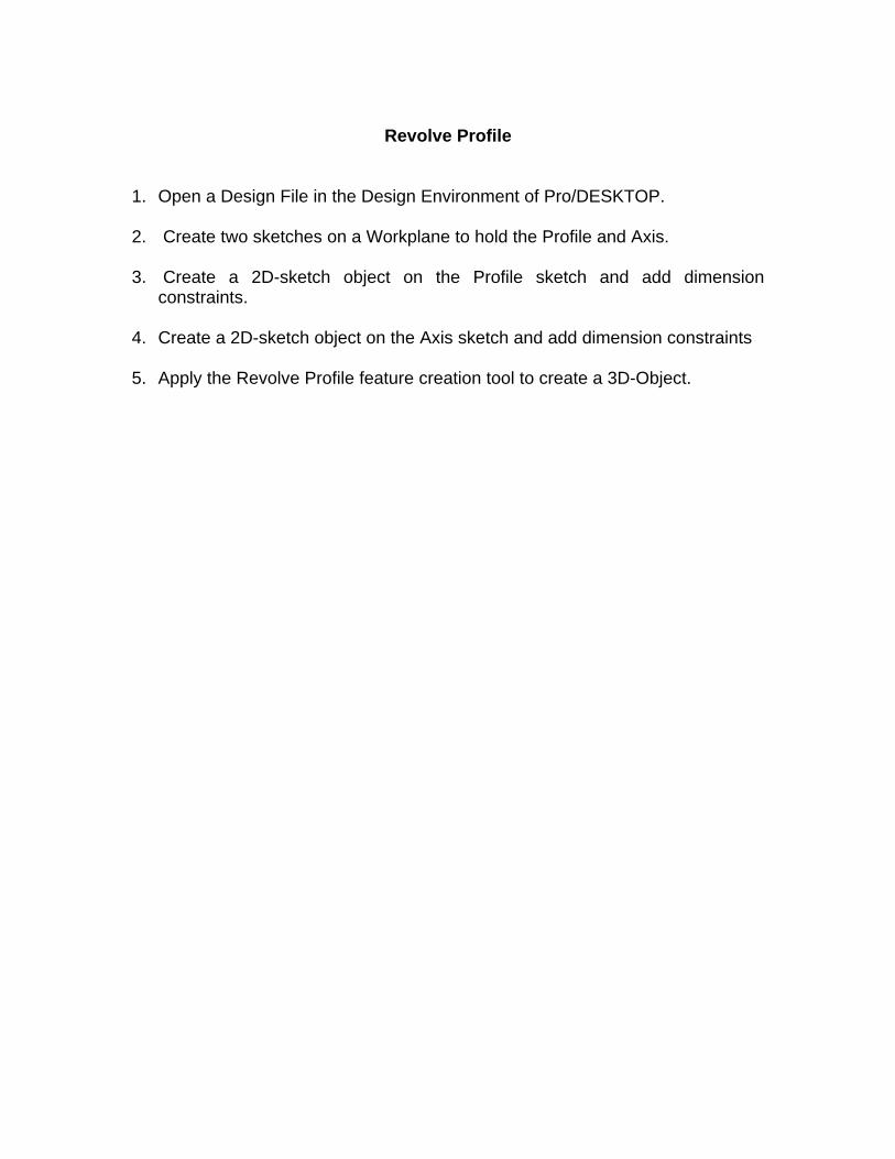
Revolve Profile
1. Open a Design File in the Design Environment of Pro/DESKTOP. 2. Create two sketches on a Workplane to hold the Profile and Axis. 3. Create a 2D-sketch object on the Profile sketch and add dimension
constraints. 4. Create a 2D-sketch object on the Axis sketch and add dimension constraints 5. Apply the Revolve Profile feature creation tool to create a 3D-Object.

When you open the Pro/DESKTOP CAD software an interface appears on screen. There are three environments in Pro/DESKTOP that enable the user to concurrently create a solid model, an orthographic drawing and a photo-realistic album rendering. This exercise will guide you through creating a solid model in the Design environment. From the Pull Down Menu select the white page icon. This icon allows you to open a new file in Pro/DESKTOP. From the New File box select Design and click on OK.
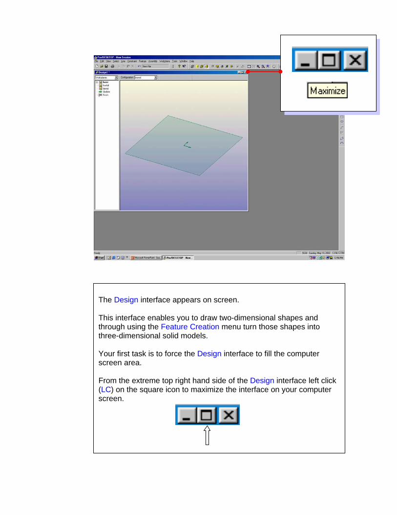
The Design interface appears on screen. This interface enables you to draw two-dimensional shapes and through using the Feature Creation menu turn those shapes into three-dimensional solid models. Your first task is to force the Design interface to fill the computer screen area. From the extreme top right hand side of the Design interface left click (LC) on the square icon to maximize the interface on your computer screen.
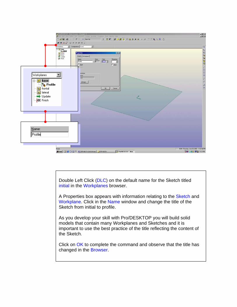
Double Left Click (DLC) on the default name for the Sketch titled initial in the Workplanes browser. A Properties box appears with information relating to the Sketch and Workplane. Click in the Name window and change the title of the Sketch from initial to profile. As you develop your skill with Pro/DESKTOP you will build solid models that contain many Workplanes and Sketches and it is important to use the best practice of the title reflecting the content of the Sketch. Click on OK to complete the command and observe that the title has changed in the Browser.

Move the cursor over the name of the first Workplane (base) in the Workplanes browser. Right Click to reveal the following sub menu. Select New Sketch from the menu. A Properties box appears with information relating to the Sketch andWorkplane. Click in the Name window and change the title of the Sketch from initial to Axis.

The Workplane can be repositioned to make drawing two-dimensional shapes easier. LC on the yellow cube icon with the top surface shaded in gray from the Views Toolbar The Workplane will change to an orthographic plan view. An alternative command sequence is from the Pull Down Menu: View / Go To / Onto Workplane.
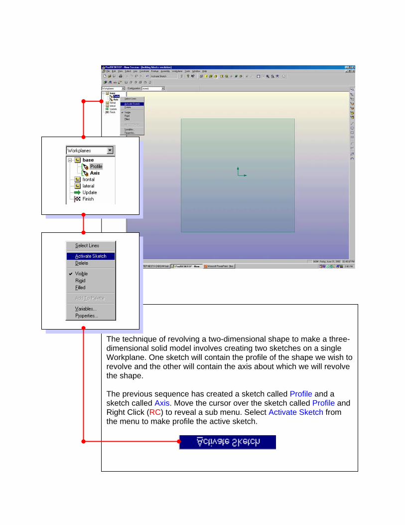
The technique of revolving a two-dimensional shape to make a three-dimensional solid model involves creating two sketches on a single Workplane. One sketch will contain the profile of the shape we wish to revolve and the other will contain the axis about which we will revolve the shape. The previous sequence has created a sketch called Profile and a sketch called Axis. Move the cursor over the sketch called Profile and Right Click (RC) to reveal a sub menu. Select Activate Sketch from the menu to make profile the active sketch.

Click on the Straight Line icon from the Design Toolbar. Move the cursor to the intersection of the green axis until the readout shows 0,0. Hold down the Shift key on the keyboard and draw a line by holding down the Left Mouse Button (LMB) and drawing vertically upward until the readout approaches 0,100. Release the LMB and then release the Shift key. The Shift key limits the command to a vertical or horizontal line.

The next sequence will guide you through dimensioning the line and creating the profile that you will revolve around an axis to produce the solid model. Select the Autoscale selection icon from the Views toolbar from the top of the screen. The line will be move to a central position. Select Halfscale selection to reduce the image by half. Tip: use the quick key selection of shift A then shift H to achieve the same result.

Pro/DESKTOP uses a Parametric system of dimensioning. This means that the dimensions attached to the two-dimensional shapes not only inform the user of the size but they also control or drive the size. Dimension driven CAD technology offers the user a great deal of creative freedom. Click on the Sketch Dimension icon in the Design Toolbar. This tool will allow you to attach a linear dimension to the straight line. Move the cursor over the line, the line will change colour to show it is selected. Hold down the LMB and drag out a dimension line as shown above.

Click on the Select Constraints icon in the Design Toolbar Move the cursor over the numbers of the dimension you have just attached and Double Left Click (DLC) to gain access to the Properties box. Change the Length value to 100 mm and click on OK to complete the command.
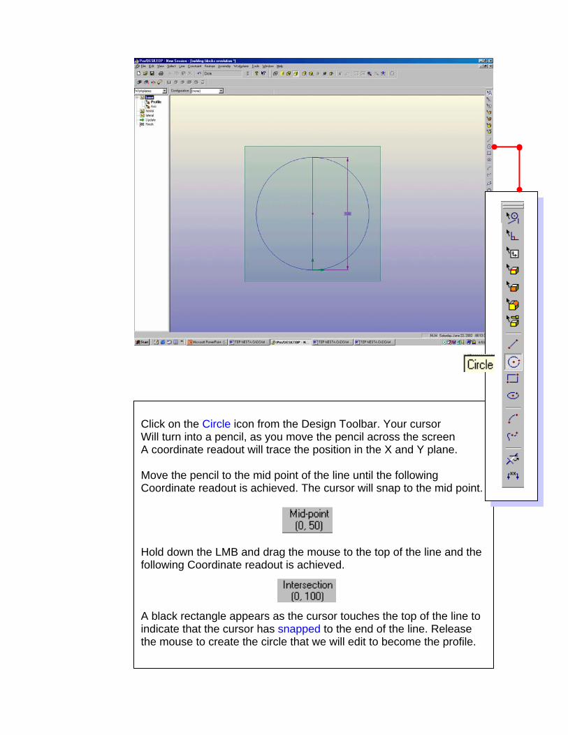
Click on the Circle icon from the Design Toolbar. Your cursor Will turn into a pencil, as you move the pencil across the screen A coordinate readout will trace the position in the X and Y plane. Move the pencil to the mid point of the line until the following Coordinate readout is achieved. The cursor will snap to the mid point. Hold down the LMB and drag the mouse to the top of the line and the following Coordinate readout is achieved. A black rectangle appears as the cursor touches the top of the line to indicate that the cursor has snapped to the end of the line. Release the mouse to create the circle that we will edit to become the profile.

Click on the Delete Line Segment icon in the Design Toolbar. The cursor changes to a pair of scissors. Move the scissor icon over the LEFT side of the circle. As you place the scissors over the left half of the circle the circumference highlights to show it is about to be deleted. The Delete Line Segment command will use the straight line you created at the start of this exercise as a cutting plane. Left Click over the left side of the circle to delete that segment and leave a semi-circle as shown above. A cutting plane separates the line segment you wish to delete from the line segment you wish to remain in place. This shape represents the profile of the solid model and has been created on the sketch called Profile.

To create a solid model using the Revolve Profile technique it is essential to create two separate sketches on the same Workplane. One sketch should be called Profile and contain the shape of the profile to be revolved. The second sketch should be called Axis and contain the axis about which the profile will be revolved.
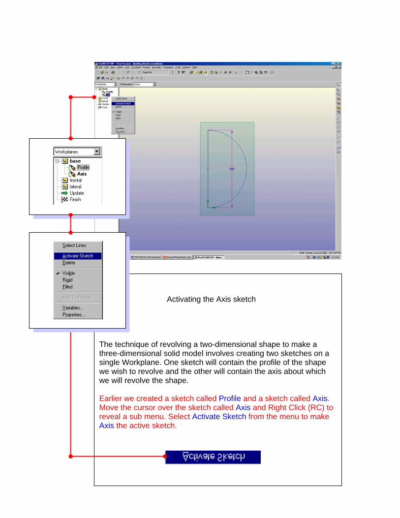
Activating the Axis sketch The technique of revolving a two-dimensional shape to make a three-dimensional solid model involves creating two sketches on a single Workplane. One sketch will contain the profile of the shape we wish to revolve and the other will contain the axis about which we will revolve the shape. Earlier we created a sketch called Profile and a sketch called Axis. Move the cursor over the sketch called Axis and Right Click (RC) to reveal a sub menu. Select Activate Sketch from the menu to make Axis the active sketch.

Click on the Straight Line icon from the Design Toolbar. Move the cursor to the intersection of the axis, straight line and the semi-circle until the readout shows intersection 0,0. Hold down the Shift key on the keyboard and draw a line by holding down the Left Mouse Button (LMB) and drawing vertically upward until the line snaps to the end and the readout indicates end 0,100. Release the LMB and then release the Shift key. The Shift key limits the command to a vertical or horizontal line.

Checking the contents of the Axis and Profile sketch.
Move the cursor over the sketch name axis in the Browser. RC and choose Select Lines from the sub menu. A single red line will activate to show what is drawn on the Axis sketch. Repeat the procedure to show the semi-circle drawn on the Profile sketch.

Axis Profile
The next sequence will guide you through creating a solid model by revolving a profile. First change the viewpoint to a 3D view by selecting View Trimetric from the Views Toolbar. Select the Autoscale selection icon from the Views toolbar from the top of the screen. The line will be move to a central position. Select Halfscale selection to reduce the image by half. Tip: use the quick key selection of shift A then shift H to achieve the same result.

You are ready to create a three-dimensional feature from the two-dimensional semi-circle. From the pull down menu select: Feature – Revolve Profile. An alternative is to select the Revolve Profile icon. In the Revolve Profile box set the angle to 270.

Make sure this window contains the Profile sketch. Make sure this window contains the Axis sketch. Click on OK to complete the command and revolve the semi-circle 270 degrees around the axis line.

This button ensures the two-dimensional shape creates a solid form by adding material.
This window describes the name of the sketch that contains the Profile.
This window contains the name of the Feature. You can change this to reflect the description of your design.
This window describes the name of the sketch that contains the Axis.
This button ensures the two-dimensional shape creates a solid form by adding material above or below the Workplane.
This window enables you to set the exact value the two-dimensional semi-circle is revolved into a three-dimensional feature.