product 19xt data hermetic centrifugal liquid...
TRANSCRIPT

Reduced operating costs areachieved through an improvement tothe basic refrigeration cycle thatincorporates a turbine to recover en-ergy that would otherwise be lostin the expansion portion of the vaporcompression cycle. This industryleading technology captures a por-tion of the potential energy that existsas a result of the pressuredifferential between the condenserand evaporator. The turbine willreceive positive pressure HFC-134arefrigerant from the condenser anduse energy from this high pressurerefrigerant to supplement energy fur-nished by the chiller’smotor, reducing external energyrequirements.
Features/Benefits• Using a patented two phase flowturbine expander energy reclaimsystem, the 19XT reduces energyconsumption costs significantly. Thehigh efficiency design will oftenqualify for utility rebates in manyareas of the world.
• Uses environmentally preferredchlorine free HFC-134a refrigerantwhich has zero ozone depletionpotential and is considered one ofthe safest refrigerants available.HFC-134a is being used in automo-bile air conditioning systems to-day. With production capacityincreasing you are assured of futureavailability and reduced costs.
• Reliability is designed in with onlyone additional rotating compres-sor part as compared to our 19XLcentrifugal compressor. The 19XTonly adds a turbine wheel andnozzle block to the already provenreliable 19XL compressor.
ProductData
19XTHermetic Centrifugal
Liquid Chiller50/60 Hz
HFC-134a — 300 to 550 Nominal Tons (1055 to 1934 kW)
Copyright 1995 Carrier Corporation Form 19XT-1PD
AdvancedCentrifugalEngineering
Increased heat exchanger surfacereduces the Leaving TemperatureDifference (LTD) between the waterflowing through the tubes and therefrigerant on the shell side of theheat exchanger. The reduced LTDminimizes the compressor head andthus reduces gas horsepowerrequirements.A sensible subcooler was designedinto the condenser to cool the con-denser liquid to a temperature belowthe condenser saturated tempera-ture. The lower temperature increasesthe refrigeration effect, consequentlyresulting in a reduced refrigerant massflow rate and additional gas horse-power savings.High efficiency motors are incorpo-rated into the 19XT design to reducemotor electrical losses. The motorelectrical inefficiencies are convertedto heat which is removed by the circu-lating refrigerant. Unlike an openmotor design which results in increasedambient temperature, the hermeticdesign is self contained and does notrelease heat into the plant room.Positive pressure design reduceschiller size and allows for easier instal-lation within confined plant roomswhen compared to an equivalentcapacity low pressure chiller. Majorcomponents, such as the cooler, con-denser, and compressor, can be un-bolted to break down the chiller intosmaller components for simplifiedinstallation and rigging. The take-apartdesign enables the components to berigged into place separately, oftenthrough standard doorways, and thenreassembled in the plant room. Theversatile design reduces installationtime and costs.The 19XT eliminates the need fora purge unit which consequentlyreduces refrigerant loss and elimi-nates purge vent and water piping.ASME refrigerant side construc-tion assures a robust design thatincludes pressure testing and indepen-dent inspection. Each chiller is pres-sure tested on the refrigerant sideto ensure leak tight joints on the en-tire assembly. An independent, autho-rized inspector witnesses each testand other check points in the assem-bly line.
When using optional isolationvalves, the refrigerant can bestored in the condenser during com-pressor servicing. An optional unitmounted pumpout unit can transferthe charge between pressure vessels.Storage of the refrigerant chargeinside the chiller reduces refrigerantloss and transfer time.
Increased reliability, resultingin minimal downtime andlonger life, is achieved throughthe use of:A semi-hermetic compressor elimi-
nates shaft seals and the associatedwear and leakage that is characteristicof open compressor designs.The single stage compressordesign eliminates additional movingparts such as second stage adjustableguide vanes and multiple impellers.The addition of the energy reclaimturbine only adds one movingpart to the compressor. The turbineattaches to the extended motor shaftwhich was specifically designed toaccommodate the turbine.
Table of contentsPage
Features/Benefits . . . . . . . . . . . . . . . . . . . . . . . . . . . . . . . . . . . . . . . . . . . . . . . . . 1-6Model Number Nomenclature . . . . . . . . . . . . . . . . . . . . . . . . . . . . . . . . . . . . . . . . 2Machine Components . . . . . . . . . . . . . . . . . . . . . . . . . . . . . . . . . . . . . . . . . . . . . . 7,8Options and Accessories . . . . . . . . . . . . . . . . . . . . . . . . . . . . . . . . . . . . . . . . . . . . . 9Physical Data . . . . . . . . . . . . . . . . . . . . . . . . . . . . . . . . . . . . . . . . . . . . . . . . . . . 10,11Dimensions . . . . . . . . . . . . . . . . . . . . . . . . . . . . . . . . . . . . . . . . . . . . . . . . . . . . . . . 12Performance Data . . . . . . . . . . . . . . . . . . . . . . . . . . . . . . . . . . . . . . . . . . . . . . . 13-16Typical Piping and Wiring . . . . . . . . . . . . . . . . . . . . . . . . . . . . . . . . . . . . . . . . 16,17Electrical Data . . . . . . . . . . . . . . . . . . . . . . . . . . . . . . . . . . . . . . . . . . . . . . . . . . . . 18Controls . . . . . . . . . . . . . . . . . . . . . . . . . . . . . . . . . . . . . . . . . . . . . . . . . . . . . . . . 19-23Control Wiring Schematic . . . . . . . . . . . . . . . . . . . . . . . . . . . . . . . . . . . . . . . . . . 24Typical Field Wiring . . . . . . . . . . . . . . . . . . . . . . . . . . . . . . . . . . . . . . . . . . . . . . 25-28Application Data . . . . . . . . . . . . . . . . . . . . . . . . . . . . . . . . . . . . . . . . . . . . . . . . 29-32Guide Specifications . . . . . . . . . . . . . . . . . . . . . . . . . . . . . . . . . . . . . . . . . . . . . 33-39
Model number nomenclature
ASME‘U‘ Stamp
ARI (Air Conditioningand Refrigeration
Institute)Performance Certified
2

TAKE APART DESIGN• Flanged/bolted design allows easydisassembly and reassembly forrigging into confined plant rooms
• Modular design reduces disassemblytime and cost
19XT HERMETIC CENTRIFUGAL LIQUID CHILLER• Highest efficiency, chlorine free, positive pressure chiller in the world• Utilizes HFC-134a, considered one of the safest refrigerants available• Utilizes proven compressor technology and adds only one additionalmoving part to the 19XL compressor
• Take apart design allows installation into confined plant rooms
TWO PHASE FLOW TURBINE EXPANDER ENERGY RECLAIM SYSTEM• Captures energy that otherwise would be lost in the expansion portionof the vapor compression cycle
• Two phase flow turbine utilizes pressure differential between condenserand cooler to drive the turbine to supplement motor power
• Simple and reliable design adds only one moving part (the turbine wheel)to the proven 19XL compressor design
HERMETIC SINGLE STAGE HIGH EFFICIENCY COMPRESSOR• High efficiency, single-stage impeller and tunnel diffuser reduce operating costs• Hermetic design eliminates disposal problems associated with oil leakage throughopen compressor shaft seals and also eliminates motor heat rejected to plant room
• Single-stage design simplifies servicing and reduces maintenance costs• Steel-backed, babbitt lined, journal bearings and Kingsbury-type thrust bearingincrease reliability
3

Features/Benefits (cont)
MICROPROCESSOR CONTROLS• 16 line by 40 character LCD display• ‘‘All in one glance’’ access to key chiller operating data• Monitors over 100 functions and conditions• Displays over 125 operating and diagnostic conditions• Carrier Comfort Network (CCN) compatible
HEAT EXCHANGERS• ASME (American Society of Mechanical Engineers)refrigerant-side construction
• Available with 150 psig (1034 kPa) or 300 psig(2068 kPa) nozzle-in-head waterboxes
• High performance internally and externally enhancedtubes
• Tubing roller expanded into double grooved, tube sheetholes improves reliability
4

Steel backed, babbitt lined, com-pressor sleeve bearings and aKingsbury-type, self leveling thrustbearing further increase reliability. Thesteel backing reduces thermal expan-sion and allows for tighter clear-ances to be held between bearingsurfaces and the steel shaft. This re-duces vibration levels and increasesbearing life. The babbitt linings ofCarrier’s bearings are made of a softmetal which is well suited for awearing surface.Cool-running hermetic motorshave been proven reliable throughmore than 30 years of service.Stationary tunnel diffuser requiresno moving parts, further enhancingreliability.Microprocessor controls eliminatethe need for pressure and temperatureswitches and pressure gages.Circuit boards are encased inplastic modules to eliminate dam-age and abuse.
Microprocessor controls sim-plify use, improve chillerprotection, reduce trouble-shooting time, and provideadditional information to theoperator. The controls feature:A 16 line by 40 character back-litLCD (Liquid Crystal Display) provides‘‘all in one glance’’ access to keychiller operating data and simplifiesuse by displaying easy-to-understandmessages, instead of ‘‘coded mes-sages.’’ It displays over 125 operatingand diagnostic conditions to reducetroubleshooting time and costs.Microprocessor monitors over100 functions to protect thechiller from abnormal operatingconditions.
Built-in two chiller lead/lag con-trol with third chiller standby auto-matically starts and stops the secondchiller in a two chiller system. Lead/lag control further decreases operatingcosts by ensuring only one chiller ison during light load conditions.A 365-day real time clock allowsthe operator to program a yearlyschedule for each week, weekends,and holidays.Precise chilled water temperaturecontrol is maintained by the micro-processor controller which accuratelypositions the compressor inlet guidevanes in response to changes in thecooling load.Ramp loading ensures smooth pull-down of water loop temperature whilepreventing a rapid increase in com-pressor power consumption dur-ing the pulldown period.Demand limiting is included to limitthe power draw of the chillers dur-ing peak loading conditions. Whenincorporated into the Carrier ComfortNetwork (CCN) building automationsystem, a red line command will holdall chillers at their preset capacityand prevent any other chillers fromstarting. If a loadshed signal is received,the compressors are unloaded toavoid high demand charges wheneverpossible.Chilled water reset can be donemanually or automatically from thebuilding management system, conse-quently saving energy when warmerchilled water can be utilized.Soft stop unloading option allowsthe guide vanes to close to a con-figured amperage level before stop-ping the compressor, possibly arequirement of your electrical distribu-tion system.
With the addition of the Chiller-visor System Manager (CSM), theentire chiller plant, including chill-ers, pumps, valves, and cooling tow-ers can be automatically controlledto reduce the overall plant power con-sumption. Multiple chillers are se-quenced to ensure the lowest possiblepower consumption during reducedloading conditions.Battery backup provides protectionduring power failures and eliminatestime consuming controlreconfiguration.An alarm file maintains the last 25time and date stamped alarm andalert messages in memory to reducetroubleshooting time and cost.Capacity override mode keeps thechiller on line to reduce nuisance shut-downs. This function unloads thecompressor whenever key safety limitsare approached.An automated controls test can beexecuted prior to start-up to verifythat the entire chiller control system isfunctioning properly.Optional modules offer uniquecontrol expandability. Carrier’sdataport module can translate itsmicroprocessor information into anASCII stream of data which can beread by any building management sys-tem.
5

Features/Benefits (cont)
19XT Refrigeration Cycle
The compressor continuously draws refrigerant vapor fromthe cooler at a rate determined by the amount of guide vaneopening. As the compressor suction reduces the pressurein the cooler, the remaining refrigerant boils at a low tem-perature (typically 38 to 42 F [3 to 6 C]). The energy re-quired for boiling is obtained from the water flowing throughthe cooler tubes. When the heat energy is removed, thewater becomes cold enough for use in an air conditioningchilled water loop or process liquid cooling system.After taking heat from the water, the refrigerant vapor is
compressed. Compression adds still more heat energy andthe refrigerant is very warm (typically 130 to 160 F [54 to71 C]) when it is discharged from the compressor into thecondenser.Relatively cool (typically 65 to 90 F [18 to 32 C]) water
flowing through the condenser tubes removes heat from therefrigerant and the vapor condenses to a liquid. Further re-moval of heat from the refrigerant occurs in the lower cham-ber of the condenser, which is called the sensible subcooler.At this point, the liquid refrigerant is subcooled by contactwith the coolest (entering water) condenser tubes.
After leaving the sensible subcooler section of the con-denser, the liquid refrigerant enters the float valve chamber.The main float valve maintains a liquid level in the subcoolerto prevent hot gas bypass from the condenser to the coolerat part load conditions. A second valve in the float valvechamber opens at part load conditions when the liquid levelincreases in the condenser to bypass liquid from the floatchamber directly to the cooler inlet. The liquid refrigerantthen flows into the turbine housing chamber on the com-pressor. The liquid refrigerant passes through the turbinenozzles and impacts the turbine blades where energy is re-claimed as the refrigerant expands through the turbine tothe lower cooler pressure. The turbine wheel is attached tothe motor shaft which allows the turbine to supplement andreduce motor power requirements. At this point the refrig-erant flashes to a mixture of gas and liquid which removesheat from the remaining liquid. This mixture flows back tothe cooler where it is now at the same temperature andpressure at which the cycle began.
19XT REFRIGERATION CYCLE
6

Machine components
COMPRESSOR COMPONENTS
LEGEND1 — Turbine Housing 8 — Motor Shaft Journal Bearings 15 — Pipe Diffuser2 — Turbine Wheel 9 — Low Speed Bull Gear 16 — High Speed Pinion Gear3 — Turbine Nozzles 10 — High Speed Shaft Thrust Bearing 17 — Oil Pump4 — Turbine Nozzle Block 11 — High Speed Shaft Journal Bearing 18 — High Speed Shaft Journal Bearing5 — Motor Shaft Extension 12 — Variable Inlet Guide Vanes 19 — Oil Pump Motor6 — Motor Stator 13 — Impeller Shroud 20 — Oil Filter7 — Motor Rotor 14 — Impeller 21 — Oil Filter Cover
7
Machine components (cont)
RIGHT END VIEW
321 1514
1920 1618 17
13124 5 6 1110987
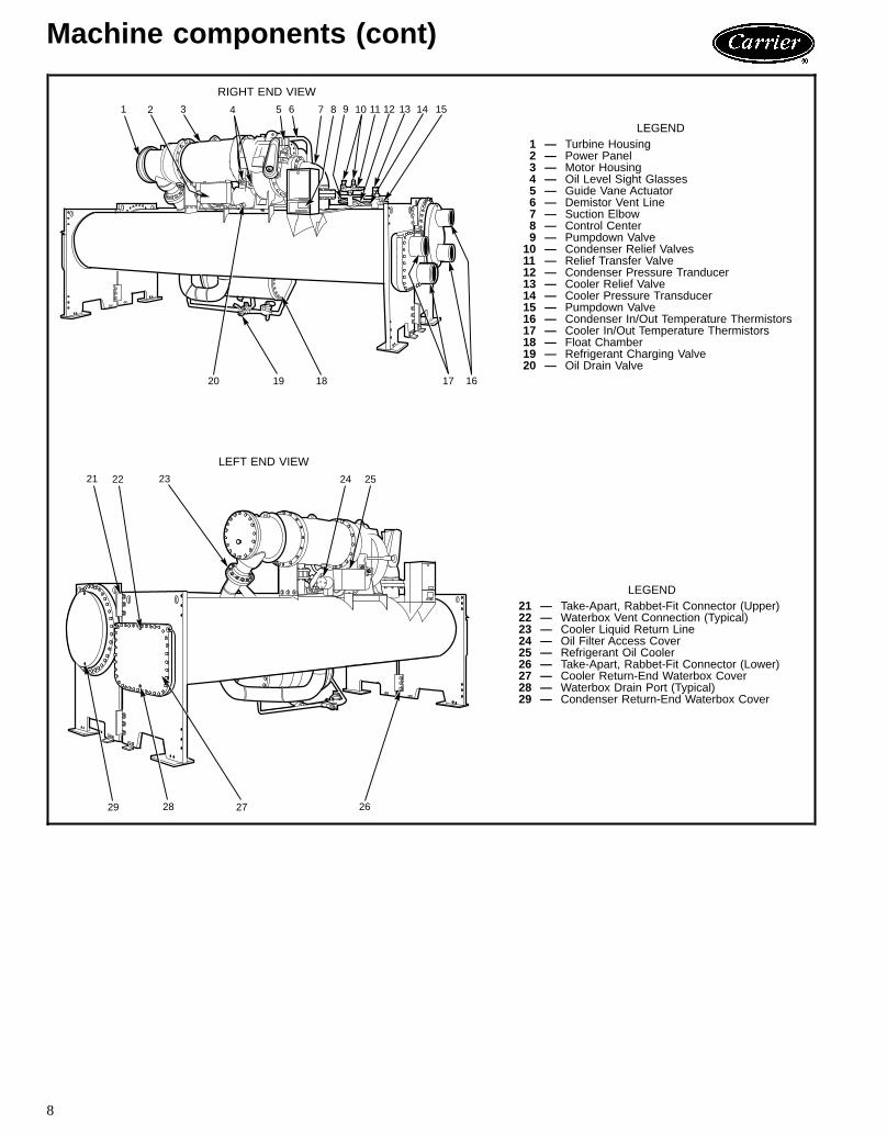
LEGEND1 — Turbine Housing2 — Power Panel3 — Motor Housing4 — Oil Level Sight Glasses5 — Guide Vane Actuator6 — Demistor Vent Line7 — Suction Elbow8 — Control Center9 — Pumpdown Valve10 — Condenser Relief Valves11 — Relief Transfer Valve12 — Condenser Pressure Tranducer13 — Cooler Relief Valve14 — Cooler Pressure Transducer15 — Pumpdown Valve16 — Condenser In/Out Temperature Thermistors17 — Cooler In/Out Temperature Thermistors18 — Float Chamber19 — Refrigerant Charging Valve20 — Oil Drain Valve
LEFT END VIEW
2829
232221 2524
2627
LEGEND21 — Take-Apart, Rabbet-Fit Connector (Upper)22 — Waterbox Vent Connection (Typical)23 — Cooler Liquid Return Line24 — Oil Filter Access Cover25 — Refrigerant Oil Cooler26 — Take-Apart, Rabbet-Fit Connector (Lower)27 — Cooler Return-End Waterbox Cover28 — Waterbox Drain Port (Typical)29 — Condenser Return-End Waterbox Cover
8
Options and accessories
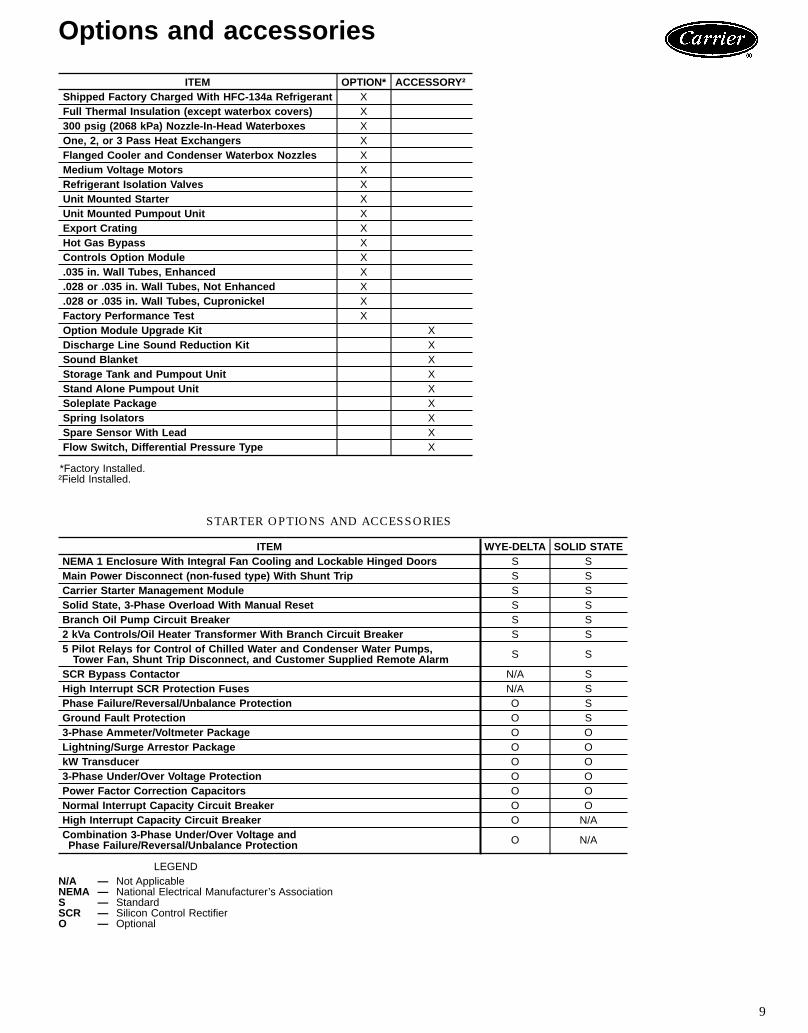
ITEM OPTION* ACCESSORY†Shipped Factory Charged With HFC-134a Refrigerant XFull Thermal Insulation (except waterbox covers) X300 psig (2068 kPa) Nozzle-In-Head Waterboxes XOne, 2, or 3 Pass Heat Exchangers XFlanged Cooler and Condenser Waterbox Nozzles XMedium Voltage Motors XRefrigerant Isolation Valves XUnit Mounted Starter XUnit Mounted Pumpout Unit XExport Crating XHot Gas Bypass XControls Option Module X.035 in. Wall Tubes, Enhanced X.028 or .035 in. Wall Tubes, Not Enhanced X.028 or .035 in. Wall Tubes, Cupronickel XFactory Performance Test XOption Module Upgrade Kit XDischarge Line Sound Reduction Kit XSound Blanket XStorage Tank and Pumpout Unit XStand Alone Pumpout Unit XSoleplate Package XSpring Isolators XSpare Sensor With Lead XFlow Switch, Differential Pressure Type X
*Factory Installed.†Field Installed.
STARTER OPTIONS AND ACCESSORIES
ITEM WYE-DELTA SOLID STATENEMA 1 Enclosure With Integral Fan Cooling and Lockable Hinged Doors S SMain Power Disconnect (non-fused type) With Shunt Trip S SCarrier Starter Management Module S SSolid State, 3-Phase Overload With Manual Reset S SBranch Oil Pump Circuit Breaker S S2 kVa Controls/Oil Heater Transformer With Branch Circuit Breaker S S5 Pilot Relays for Control of Chilled Water and Condenser Water Pumps,Tower Fan, Shunt Trip Disconnect, and Customer Supplied Remote Alarm S S
SCR Bypass Contactor N/A SHigh Interrupt SCR Protection Fuses N/A SPhase Failure/Reversal/Unbalance Protection O SGround Fault Protection O S3-Phase Ammeter/Voltmeter Package O OLightning/Surge Arrestor Package O OkW Transducer O O3-Phase Under/Over Voltage Protection O OPower Factor Correction Capacitors O ONormal Interrupt Capacity Circuit Breaker O OHigh Interrupt Capacity Circuit Breaker O N/ACombination 3-Phase Under/Over Voltage andPhase Failure/Reversal/Unbalance Protection O N/A
LEGENDN/A — Not ApplicableNEMA — National Electrical Manufacturer’s AssociationS — StandardSCR — Silicon Control RectifierO — Optional
9

Physical data
COMPRESSOR/MOTOR WEIGHTSLOW-VOLTAGE MOTORS
MOTORSIZE
ENGLISH SICompressorWeight (lb)
CompressorWeight (lb)
StatorWeight (lb)
RotorWeight (lb)
CompressorWeight (kg)
CompressorWeight (kg)
StatorWeight (kg)
RotorWeight (kg)
60 Hz 50 Hz 60 Hz 50 Hz 60 Hz 50 Hz 60 Hz 50 Hz 60 Hz 50 Hz 60 Hz 50 HzCD 5543 5642 1402 1477 331 355 2514 2559 636 670 150 161CE 5571 5675 1427 1502 334 363 2527 2574 647 681 151 165CL 5609 5741 1452 1552 347 379 2544 2604 659 704 157 172CM 5626 5774 1465 1577 351 387 2551 2619 664 715 159 176CN 5642 5785 1477 1584 355 391 2559 2624 670 718 161 177CP 5708 5807 1527 1602 371 395 2589 2634 693 727 168 179CQ 5774 5807 1577 1602 387 395 2619 2634 715 727 176 179CR 5807 5807 1602 1602 395 395 2634 2634 727 727 179 179
NOTE: Compressor weight includes rotor, stator, and suction and discharge elbow weights.
MEDIUM-VOLTAGE MOTORS
MOTORSIZE
ENGLISH SICompressorWeight (lb)
CompressorWeight (lb)
StatorWeight (lb)
RotorWeight (lb)
CompressorWeight (kg)
CompressorWeight (kg)
StatorWeight (kg)
RotorWeight (kg)
60 Hz 50 Hz 60 Hz 50 Hz 60 Hz 50 Hz 60 Hz 50 Hz 60 Hz 50 Hz 60 Hz 50 HzCD 5287 5297 1224 1216 253 271 2398 2402 555 551 115 123CE 5329 5355 1257 1263 262 282 2417 2429 570 573 119 128CL 5341 5370 1265 1275 266 285 2422 2435 574 578 121 129CM 5382 5426 1298 1322 274 294 2441 2461 589 600 124 133CN 5409 5475 1318 1361 281 304 2453 2483 598 617 127 138CP 5440 5536 1347 1417 283 309 2467 2511 611 643 128 140CQ 5534 5673 1423 1526 301 337 2510 2573 645 692 137 153CR 5570 5689 1452 1533 308 346 2526 2580 659 695 140 157
NOTE: Compressor weight includes rotor, stator, and suction and dischrage elbow weights.
HEAT EXCHANGER WEIGHTS
CODEENGLISH SI
Rigging Weight (lb)* Refrigerant (lb) Water (lb) Rigging Weight (kg)* Refrigerant (kg) Water (kg)Cooler Condenser Cooler Condenser Cooler Condenser Cooler Condenser Cooler Condenser Cooler Condenser
60 8,997 10,050 1230 1580 800 1023 4080 4558 558 717 363 46461 9,462 10,610 1480 1580 933 1183 4291 4812 671 717 423 53762 9,926 11,156 1720 1580 1065 1339 4502 5059 780 717 483 60763 10,391 11,703 1970 1580 1198 1495 4712 5307 893 717 543 678
LEGENDNIH — Nozzle-In-Head
*Rigging weights include .035-in. wall copper tubes, NIH waterboxes with flanges.For specific machine weights, refer to the Computer Selection Program.
10

WATERBOX COVER WEIGHTS
HEATEXCHANGER
WATERBOXDESCRIPTION
ENGLISH SIFrame 6, Std Nozzles Frame 6, Flanged Frame 6, Std Nozzles Frame 6, Flanged150 psig 300 psig 150 psig 300 psig 1034 kPa 2068 kPa 1034 kPa 2068 ka
COOLER
NIH, 1 Pass Cover 590 842 630 919 268 382 286 417NIH, 2 Pass Cover 586 832 642 904 266 378 291 410NIH, 3 Pass Cover 610 875 627 947 277 397 284 429
NIH, Plain End Cover 479 616 — — 218 280 — —
CONDENSER
NIH, 1 Pass Cover 770 1087 820 1164 350 494 372 528NIH, 2 Pass Cover 806 1104 862 1216 366 501 391 551NIH, 3 Pass Cover 827 1148 844 1184 376 521 383 537
NIH, Plain End Cover 687 901 — — 312 409 — —
LEGENDNIH — Nozzle-In-Head
NOTE: The waterbox cover weights are included in the heat exchanger weights shown on page 10.
WATERBOX NOZZLE SIZES
FRAME PASSNOMINAL PIPE SIZE (in.) ACTUAL PIPE ID (in.)Cooler Condenser Cooler Condenser
61 10 10 10.020 10.0202 8 8 7.981 7.9813 6 6 6.065 6.065
LEGENDID — Inside Diameter
COMPONENT WEIGHTS
COMPONENT lb kgSuction Elbow* 54 25Discharge Elbow* 46 21Control Cabinet† 30 14Optional Mounted Starter** 500 227
*Included in total compressor weight.†Included in total cooler weight.**Weight of optional factory-mounted starter is not included and mustbe added to heat exchanger weights.
11

Dimensions
WATERBOX ANDNOZZLE TYPE
A (Length)B (Width C (Height) NOZZLE SIZE (in.)
(Nominal Pipe Size)2 Pass* 1 or 3 Pass†ft-in. mm ft-in. mm ft-in. mm ft-in. mm 1-Pass 2-Pass 3-Pass
150 psig (1034 kPa) Std Nozzles 17-71⁄2 5372 18-31⁄2 5575.3 7-1 2159 8-515⁄16 2589 10 8 6300 psig (2068 kPa) Std Nozzles 17-9 5410 18-51⁄2 5626.1 7-1 2159 8-515⁄16 2589 10 8 6150 psig (1034 kPa) Flanged Nozzles 17-77⁄8 5382 18-41⁄4 5594 7-1 2159 8-515⁄16 2589 10 8 6300 psig (2068 kPa) Flanged Nozzles 17-97⁄8 5420 18-61⁄4 5645 7-1 2159 8-515⁄16 2589 10 8 6
*Assumes both cooler and condenser nozzles on same end of chiller.†1 or 3 pass length applies if either (or both) cooler or condenser is a 1 or 3 pass design.
NOTES:1. Service access should be provided per American Society of Heating, Refrigeration, and Air
Conditioning Engineers (ASHRAE) 15, latest edition, National Fire Protection Association(NFPA) 70, and local safety code.
2. Allow at least 3 ft (915 mm) overhead clearance for service rigging.3. Certified drawings available upon request.4. [ ] indicates millimeters.
12

Performance data
COOLER PRESSURE DROP19XT, 1 PASS COOLER, NOZZLE-IN-HEADTURBO-B II, 0.025 IN. WALL TUBING
FRESH WATER AT 50 F, WATER VELOCITIES FROM 3 TO 12 FT/SEC
19XT, 2 PASS COOLER, NOZZLE-IN-HEADTURBO-B II, 0.025 IN. WALL TUBING
FRESH WATER AT 50 F, WATER VELOCITIES FROM 3 TO 12 FT/SEC
LEGENDHX — Heat Exchanger
NOTES:1. HX-- designations are cooler heat exchanger sizes.2. To determine pressure drops more accurately and to compensate for actual water temperature, use the com-
puterized selection service available through your local Carrier Sales office.
13

Performance data (cont)
COOLER PRESSURE DROP19XT, 3 PASS COOLER, NOZZLE-IN-HEADTURBO-B II, 0.025 IN. WALL TUBING
FRESH WATER AT 50 F, WATER VELOCITIES FROM 3 TO 12 FT/SEC
LEGENDHX — Heat Exchanger
NOTES:1. HX-- designations are cooler heat exchanger sizes.2. To determine pressure drops more accurately and to compensate for actual water temperature, use the com-
puterized selection service available through your local Carrier Sales office.
CONDENSER PRESSURE DROP19XT, 1 PASS CONDENSER, NOZZLE-IN-HEADCARRIER SPIKE FIN, 0.025 IN. WALL TUBING
FRESH WATER AT 90 F, WATER VELOCITIES FROM 3 TO 12 FT/SEC
LEGENDHX — Heat Exchanger
NOTES:1. HX-- designations are condenser heat exchanger sizes.2. To determine pressure drops more accurately and to compensate for actual water temperature, use the com-
puterized selection service available through your local Carrier Sales office.
14

CONDENSER PRESSURE DROP19XT, 2 PASS CONDENSER, NOZZLE-IN-HEADCARRIER SPIKE FIN, 0.025 IN. WALL TUBING
FRESH WATER AT 90 F, WATER VELOCITIES FROM 3 TO 12 FT/SEC
19XT, 3 PASS CONDENSER, NOZZLE-IN-HEADCARRIER SPIKE FIN, 0.025 IN. WALL TUBING
FRESH WATER AT 90 F, WATER VELOCITIES FROM 3 TO 12 FT/SEC
LEGENDHX — Heat Exchanger
NOTES:1. HX-- designations are condenser heat exchanger sizes.2. To determine pressure drops more accurately and to compensate for actual water temperature, use the com-
puterized selection service available through your local Carrier Sales office.
15
Peformance data (cont)
Compressor motor controllersCompressor motors, as well as controls and accessories,require the use of starting equipment systems specificallydesigned for 19XT chillers. Refer to Carrier EngineeringRequirement Z-375 or consult Carrier regarding design in-formation for the selection of controllers.
Capacitors/power factorsPower factor considerations may indicate use of capacitors.Properly sized capacitors improve power factors, especiallyat part load. The 19XT Computer Selection programcan select the proper capacitor size required for yourapplication.
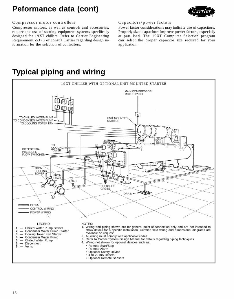
Typical piping and wiring19XT CHILLER WITH OPTIONAL UNIT-MOUNTED STARTER
LEGEND1 — Chilled Water Pump Starter2 — Condenser Water Pump Starter3 — Cooling Tower Fan Starter4 — Condenser Water Pump5 — Chilled Water Pump6 — Disconnect7 — Vents
NOTES:1. Wiring and piping shown are for general point-of-connection only and are not intended to
show details for a specific installation. Certified field wiring and dimensional diagrams areavailable on request.
2. All wiring must comply with applicable codes.3. Refer to Carrier System Design Manual for details regarding piping techniques.4. Wiring not shown for optional devices such as:
• Remote Start/Stop• Remote Alarm• Optional Safety Device• 4 to 20 mA Resets• Optional Remote Sensors
16
Typical piping and wiring (cont)
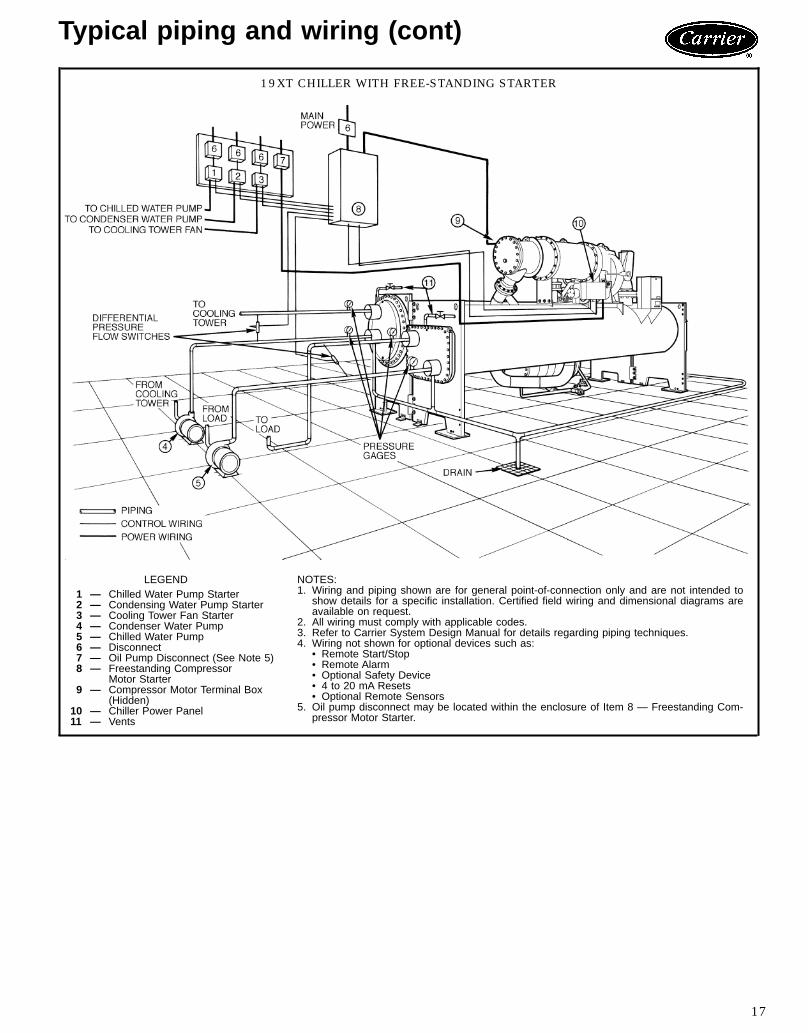
19XT CHILLER WITH FREE-STANDING STARTER
LEGEND1 — Chilled Water Pump Starter2 — Condensing Water Pump Starter3 — Cooling Tower Fan Starter4 — Condenser Water Pump5 — Chilled Water Pump6 — Disconnect7 — Oil Pump Disconnect (See Note 5)8 — Freestanding Compressor
Motor Starter9 — Compressor Motor Terminal Box
(Hidden)10 — Chiller Power Panel11 — Vents
NOTES:1. Wiring and piping shown are for general point-of-connection only and are not intended to
show details for a specific installation. Certified field wiring and dimensional diagrams areavailable on request.
2. All wiring must comply with applicable codes.3. Refer to Carrier System Design Manual for details regarding piping techniques.4. Wiring not shown for optional devices such as:
• Remote Start/Stop• Remote Alarm• Optional Safety Device• 4 to 20 mA Resets• Optional Remote Sensors
5. Oil pump disconnect may be located within the enclosure of Item 8 — Freestanding Com-pressor Motor Starter.
17
Electrical data
MOTORSIZE
MOTORELECTRICAL
CHARACTERISTICS
60 Hz MOTORS 50 Hz MOTORSLow Volts Medium Volts Low Volts Medium Volts
MaxIkW 200 v 230 v 380 v 416 v 460 v 575 v Max
IkW 2400 v 3300 v 4160 v MaxIkW 230 v 346 v 400 v Max
IkW 3000 v 3300 v
CDRLA per IkW
1963.22 2.88 1.81 1.68 1.43 1.17
200.274 .199 .158
1962.94 2.03 1.74
200.212 .199
LRA Star 1518 1560 1039 1016 782 618 — — — 1477 1145 935 — —LRA Delta 5264 5392 3568 3495 2696 2134 255 199 147 5115 3952 3085 194 194
CERLA per IkW
2143.22 2.87 1.81 1.87 1.43 1.17
219.272 .196 .155
2142.93 1.96 1.74
219.219 .197
LRA Star 1680 1649 1146 1100 847 699 — — — 1601 1111 1014 — —LRA Delta 5814 5836 3938 3787 2923 2412 284 210 164 5545 3843 3344 214 212
CLRLA per IkW
2393.31 2.86 1.86 1.62 1.43 1.17
243.272 .200 .157
2392.9 1.93 1.77
243.212 .196
LRA Star 2232 1874 1366 1071 937 759 — — — 1730 1154 1228 — —LRA Delta 7670 6457 4698 3694 3228 2620 281 227 178 5994 4006 4045 241 236
CMRLA per IkW
2623.42 2.88 1.80 1.6 1.43 1.19
267.272 .199 .159
2622.91 1.93 1.76
267.220 .200
LRA Star 2825 2143 1348 1058 1046 912 — — — 1959 1253 1307 — —LRA Delta 9704 7375 4649 3653 3608 3149 313 261 198 6765 4343 4310 258 254
CNRLA per IkW
2903.34 2.84 1.76 1.68 1.41 1.17
295.272 .198 .156
2902.86 1.9 1.72
295.216 .194
LRA Star 2796 2116 1332 1458 1031 901 — — — 1922 1233 1292 — —LRA Delta 9613 7293 4604 5012 3572 3110 346 287 215 6663 4278 4266 291 285
CPRLA per IkW
3183.25 2.83 1.74 1.61 1.4 1.15
323.274 .200 .160
3182.84 1.92 1.68
323.215 .197
LRA Star 2650 2358 1408 1381 1090 951 — — — 1897 1385 1278 — —LRA Delta 9158 8118 4867 4766 3777 3292 378 320 237 6592 4801 4426 325 292
CQRLA per IkW
3543.2 2.88 1.74 1.6 1.44 1.18
360.274 .198 .160
3542.9 1.89 1.67
360.213 .194
LRA Star 2518 2889 1527 1463 1447 1169 — — — 2243 1384 1278 — —LRA Delta 8728 9955 5277 5051 4998 4035 457 329 268 7751 4812 4441 348 343
CRRLA per IkW
3883.24 2.82 1.75 1.6 1.41 1.15
140.274 .202 .157
3882.84 1.88 1.65
410.213 .195
LRA Star 3110 2824 1728 1630 1415 1137 — — — 1896 1384 1278 — —LRA Delta 10,735 9741 5960 5623 4894 3934 528 414 297 6617 4829 4453 450 438
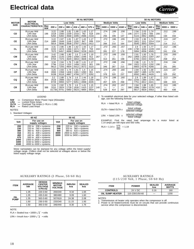
LEGENDlkW — Compressor Motor Power Input (Kilowatts)LRA — Locked Rotor AmpsOLTA — Overload Trip Amps (= RLA x 1.08)RLA — Rated Load Amps
NOTES:1. Standard Voltages:
60 HZ 50 HZ
Volt For use onsupply voltages Volt For use on
supply voltages200 200 to 208 v systems 230 220 to 240 v systems230 220 to 240 v systems 346 320 to 360 v systems380 360 to 400 v systems 400 380 to 415 v systems416 401 to 439 v systems 3000 2900 to 3100 v systems460 440 to 480 v systems 3300 3200 to 3400 v systems575 550 to 600 v systems2400 2300 to 2500 v systems3300 3150 to 3450 v systems4160 4000 to 4300 v systems
Motor nameplates can be stamped for any voltage within the listed supply/voltage range. Chillers shall not be selected at voltages above or below thelisted supply voltage range.
2. To establish electrical data for your selected voltage, if other than listed volt-age, use the following formula:
listed voltageRLA = listed RLA x selected voltage
listed voltageOLTA = listed OLTA x selected voltage
selected voltageLRA = listed LRA x listed voltage
EXAMPLE: Find the rated load amperage for a motor listed at1.14 amps per kW input and 550 volts.
575RLA = 1.14 x = 1.19550
AUXILIARY RATINGS (3 Phase, 50/60 Hz)
ITEM AVERAGEkW
DESIGNCENTERVOLTAGEV-PH-HZ
MIN/MAXMOTORVOLTAGE
INRUSHkva
SEALEDkva
OILPUMP
1.35 220-3-60 200/240 9.34 1.651.35 430-3-60 380/480 9.09 1.601.35 563-3-60 507/619 24.38 2.081.50 230-3-50 220/240 11.15 1.931.50 393-3-50 346/440 8.30 1.76
NOTE:FLA = Sealed kva • 1000/= • volts3
LRA = Inrush kva • 1000/= • volts3
AUXILIARY RATINGS(115/230 Volt, 1 Phase, 50/60 Hz)
ITEM POWER SEALED AVERAGEkva WATTS
CONTROLS 24 V DC 0.16 160OIL SUMP HEATER 115-230/1/50-60 — 1200
NOTES:1. Transmission oil heater only operates when the compressor is off.2. Power to oil heater/controls must be on circuits that can provide continuous
service when the compressor is disconnected.
18

Controls
Microprocessor controlsMicroprocessor controls provide the safety, interlock, ca-pacity control, and indications necessary to operate the chillerin a safe and efficient manner.
Control systemThe microprocessor control on each Carrier centrifugal sys-tem is factory mounted, wired, and tested to ensure ma-chine protection and efficient capacity control. In addition,the program logic ensures proper starting, stopping, andrecycling of the machine and provides a communication linkto the Carrier Comfort Network (CCN).
FeaturesControl systemComponent Test and Diagnostic CheckMenu-Driven Keypad Interface for Status Display,Set Point Control, and System Configuration
CCN CompatiblePrimary and Secondary Status MessagesIndividual Start/Stop Schedules for Local and CCNOperation Modes
Recall of Up to 25 Alarm/Alert Messages withDiagnostic Help
Two Chiller Lead/Lag with Third Chiller Standbyis Standard on the PIC Software
Optional Soft Stop Unloading Closes Guide Vanesto Unload the Motor to the Configured AmperageLevel Prior to Stopping
Safety cutoutsBearing Oil High Temperature*Motor High Temperature*†Refrigerant (Condenser) High Pressure*†Refrigerant (Cooler) Low Temperature*†Lube Oil Low PressureCompressor (Refrigerant) Discharge Temperature*Under Voltage**Over Voltage**Oil Pump Motor OverloadCooler and Condenser Water Flow††Motor Overload†Motor Acceleration TimeIntermittent Power LossCompressor Starter FaultsCompressor Surge Protection*
Capacity ControlLeaving Chilled Water ControlEntering Chilled Water ControlSoft Loading Control by Temperature or Load RampingGuide Vane Actuator ModuleHot Gas Bypass ValvePower (Demand) LimiterAuto. Chilled Water Reset
InterlocksManual/Automatic Remote StartStarting/Stopping Sequence
Pre-Lube/Post-LubePre-Flow/Post-FlowCompressor Starter Run InterlockOil Pump Interlock
Pre-Start Check of Safeties and AlertsLow Chilled Water (Load) RecycleMonitor/Number Compressor Starts and Run HoursManual Reset of Safeties
IndicationsChiller Operating Status MessagePower-OnPre-Start Diagnostic CheckCompressor Motor AmpsPre-Alarm Alert\AlarmContact for Remote AlarmSafety Shutdown MessagesElapsed Time (Hours of Operation)Chiller Input kW¶
*These can be configured by user to provide alert indica-tion at user-defined limit.†Override protection: Causes compressor to first unloadand then, if necessary, shut down.
**Will not require manual reset or cause an alarm if auto-restart after power failure is enabled.
††Required: Field or factory supplied flow switch (installedat jobsite).
\By display code only.¶kW transducer must be supplied in motor starter.
19

Controls (cont)
MICROPROCESSOR CONTROL CENTER
CONTROL CENTER WITH OPTIONS (FRONT VIEW)
LEGENDLID — Local Interface DevicePIC — Product Integrated ControlsPSIO — Processor Sensor Input/Output Module
1 — Optional 8-Input Module for Spare Inputs to ControlInterface (One of Two Available)
2 — PSIO (The PSIO is the Brain of the PIC)3 — LID Input/Output Interface Panel Display4 — LID Light and Power Supply (Hidden)5 — Power Transformer6 — 6-Pack Relay Board7 — Circuit Breakers (4)
20

LOCAL INTERFACE DEVICE (LID) TYPICAL DISPLAY PANELS
Default Display — Displays information most commonly required forchiller operating logs. Two line system status messages inform theoperator of mode of operation or any alert or alarm messages. Thefour ‘‘softkeys’’ allow access to other control functions.
Schedule Screen— Auser established occupancy schedule can eas-ily be configured for your particular application. A 365-day, real time,battery backed up clock will automatically start and stop the chiller ac-cording to your established schedule or based on the buildling masterschedule in a CCN system.
Status Screens — Displays readings of every point monitored by themicroprocessor. Cooler, condenser, and oil pressure are included inthe status screens.
Set Point Screen — The chilled water and demand limit set pointscan be entered, stored, viewed, or changed easily from this screen.
21

Controls (cont)
LOCAL INTERFACE DEVICE (LID) TYPICAL DISPLAY PANELS (cont)
Service Screens — The password protected service screens providean array of information available to the service technician to configurethe chiller for your particular application and troubleshoot any prob-lems that may occur.
The Service Configuration Screens — Allow the service technicianto configure the controls for your particular application and set over-ride and alert levels for several points monitored by the controlsystem.
Alarm History File — Stores last 25 alarms or alerts that have oc-curred along with time and date indication. Allows service technicianto quickly review alarm or alert history to identify problems that existas well as action required to resolve the problem.
The Control Test Screen — Allows access to the various controlstests available to the service technician to quickly identify sources ofproblems and to get the chiller back on line rapidly.
22

Control sequenceTo start: Local start-up (manual start-up) is initiated by press-ing the LOCAL menu softkey which is indicated on the de-fault local interface device (LID) screen. Time schedule 01must be in the occupied mode and the internal 15-minutestart-to-start and the 1-minute stop-to-start inhibit timers musthave expired. All pre-start safeties are checked to verify thatall prestart alerts and safeties are within limits (if one is notan indication of the fault will be displayed and the startaborted). The signal is sent to start the chilled water pump.Five seconds later, the condenser water pump is energized.Thirty seconds later the controls check to see if flow hasbeen confirmed by the closure of the chilled water and con-denser water flow switches. If not confirmed, it will continueto monitor flows for a maximum of five minutes. If satisfied,it checks the chilled water temperature against the controlpoint. If the temperature is less than or equal to the chilledwater control point the condenser water pump will turn offand the controls will go into a recycle mode.If the water/brine temperature is high enough the start-up
sequence continues on to check the guide vane position. Ifthe guide vanes are more than 6% open, start-up waits un-til the vanes are closed. If the vanes are closed and the oilpump pressure is less than 3 psi (21 kPa), the oil pump andtower fan relay will be energized. The controls will wait15 seconds for the oil pressure to reach a maximum of18 psi (924 kPa). After oil pressure is verified, the controlswait 15 seconds. Then the compressor start relay is ener-gized to start the compressor. Compressor ontime and serv-ice ontime ‘‘timers’’ start and the 15-minute start-to-starttimer will start 15 seconds after oil pressure was verified.Once started: The controls will enter the ramp loadingmode to slowly open the guide vanes to prevent a rapid in-crease in compressor power consumption. Once completedthe controls will enter the capacity control mode. Any fail-ure, after the compressor is energized, that results in a safety
shutdown will energize the alarm light, advance the startsin 12 hours counter by one, and display the applicable shut-down status on the liquid-crystal display (LCD) screen.Shutdown sequence: Shutdown of the chiller can occurif any of the following events happen:• The Stop button is pressed for at least one second• A recycle shutdown was initiated• Time schedule has gone into unoccupied mode• Machine protective limit has been reached and machineis in alarm
• The start/stop status is overridden to stop from the CCNnetwork or LIDOnce the controls are placed in shutdown mode the shut-
down sequence first stops the compressor by deactivatingthe start relay. The guide vanes are then brought to theclosed position. Compressor ontime and service ontimestops. The oil pump relay and chilled water/brine pump areshut down 60 seconds after the compressor stops. The con-denser water pump will be shut down when the refrigeranttemperature or entering condenser water is below pre-established limits. The 1-minute stop-to-start will now startto countdown.If optional soft stop unloading is activated once the Stop
button is pressed or the remote contacts close, the guidevanes will close, the motor will unload to a configured am-perage level, and the machine will shut down. The displaywill indicate ‘‘Shutdown in Progress.’’If the compressor motor load is greater than 10% after
shutdown, or the starter contacts remain energized, the oilpump and chilled water pump remain energized and thealarm is displayed.Restart: Restart is permitted after both inhibit timers haveexpired. If shutdown was due to a safety shutdown the re-set button must be depressed prior to restarting the chiller.
CONTROL SEQUENCE
A — START INITIATED — Prestart checksmade; evaporator pump started.
B — Condenser water pump started (5 secondsafter A).
C — Water flows verified (30 seconds to 5 min-utes maximum). Chilled water temperatureschecked against control point. Guide vaneschecked for closure. Oil pump started; towerfan control enabled.
D — Oil pressure verified (fifteen seconds mini-mum to 300 seconds maximum after C).
E — Compressor motor starts, compressor on-time and service ontime starts, 15-minute in-hibit timer starts (10 seconds after D).
F — SHUTDOWN INITIATED — Compressormotor stops, compressor ontime and serv-ice ontime stops, 1-minute inhibit timerstarts.
G — Oil pump and evaporator pumps deener-gized (60 seconds after F). Condenserpump and tower fan control may continue tooperate if condenser pressure is high. Evap-orator pump may continue if in RECYCLEmode.
O/A — Restart permitted (both inhibit timers ex-pired) (minimum of 15 minutes after E; mini-mum of 1 minute after F).
23
Control wiring schematic
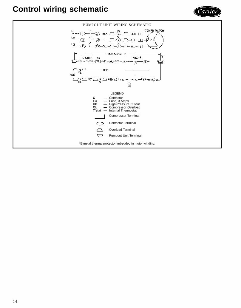
PUMPOUT UNIT WIRING SCHEMATIC
LEGENDC — ContactorFu — Fuse, 3 AmpsHP — High-Pressure CutoutOL — Compressor OverloadT’stat — Internal Thermostat
Compressor Terminal
Contactor Terminal
Overload Terminal
Pumpout Unit Terminal
*Bimetal thermal protector imbedded in motor winding.
24

Typical field wiring19XTTYPICALFIELD
WIRINGWITHOPTIONALUNIT-MOUNTEDSTA
RTER
25
Typical field wiring (cont)
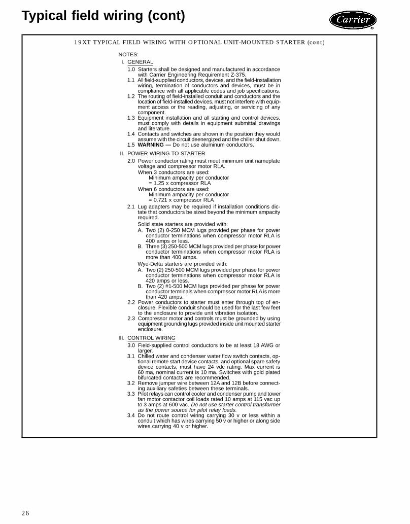
19XT TYPICAL FIELD WIRING WITH OPTIONAL UNIT-MOUNTED STARTER (cont)
NOTES:I. GENERAL:1.0 Starters shall be designed and manufactured in accordance
with Carrier Engineering Requirement Z-375.1.1 All field-supplied conductors, devices, and the field-installation
wiring, termination of conductors and devices, must be incompliance with all applicable codes and job specifications.
1.2 The routing of field-installed conduit and conductors and thelocation of field-installed devices, must not interfere with equip-ment access or the reading, adjusting, or servicing of anycomponent.
1.3 Equipment installation and all starting and control devices,must comply with details in equipment submittal drawingsand literature.
1.4 Contacts and switches are shown in the position they wouldassumewith the circuit deenergized and the chiller shut down.
1.5 WARNING — Do not use aluminum conductors.
II. POWER WIRING TO STARTER2.0 Power conductor rating must meet minimum unit nameplate
voltage and compressor motor RLA.When 3 conductors are used:
Minimum ampacity per conductor= 1.25 x compressor RLA
When 6 conductors are used:Minimum ampacity per conductor= 0.721 x compressor RLA
2.1 Lug adapters may be required if installation conditions dic-tate that conductors be sized beyond the minimum ampacityrequired.Solid state starters are provided with:A. Two (2) 0-250 MCM lugs provided per phase for power
conductor terminations when compressor motor RLA is400 amps or less.
B. Three (3) 250-500MCM lugs provided per phase for powerconductor terminations when compressor motor RLA ismore than 400 amps.
Wye-Delta starters are provided with:A. Two (2) 250-500 MCM lugs provided per phase for power
conductor terminations when compressor motor RLA is420 amps or less.
B. Two (2) #1-500 MCM lugs provided per phase for powerconductor terminals when compressor motor RLA is morethan 420 amps.
2.2 Power conductors to starter must enter through top of en-closure. Flexible conduit should be used for the last few feetto the enclosure to provide unit vibration isolation.
2.3 Compressor motor and controls must be grounded by usingequipment grounding lugs provided inside unit mounted starterenclosure.
III. CONTROL WIRING3.0 Field-supplied control conductors to be at least 18 AWG or
larger.3.1 Chilled water and condenser water flow switch contacts, op-
tional remote start device contacts, and optional spare safetydevice contacts, must have 24 vdc rating. Max current is60 ma, nominal current is 10 ma. Switches with gold platedbifurcated contacts are recommended.
3.2 Remove jumper wire between 12A and 12B before connect-ing auxiliary safeties between these terminals.
3.3 Pilot relays can control cooler and condenser pump and towerfan motor contactor coil loads rated 10 amps at 115 vac upto 3 amps at 600 vac. Do not use starter control transformeras the power source for pilot relay loads.
3.4 Do not route control wiring carrying 30 v or less within aconduit which has wires carrying 50 v or higher or along sidewires carrying 40 v or higher.
26
19XTTYPICALFIELD
WIRINGWITHFR
EE-STA
NDINGSTA
RTER
27

Typical field wiring (cont)
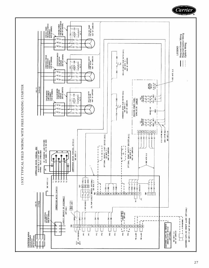
19XT TYPICAL FIELD WIRING WITH FREE-STANDING STARTER (cont)
NOTES:I. GENERAL:1.0 Starters shall be designed and manufactured in accordance
with Carrier Engineering Requirement Z-375.1.1 All field-supplied conductors, devices, and the field-installation
wiring, termination of conductors and devices, must be incompliance with all applicable codes and job specifications.
1.2 The routing of field-installed conduit and conductors and thelocation of field-installed devices, must not interfere with equip-ment access or the reading, adjusting, or servicing of anycomponent.
1.3 Equipment installation and all starting and control devices,must comply with details in equipment submittal drawingsand literature.
1.4 Contacts and switches are shown in the position they wouldassumewith the circuit deenergized and the chiller shut down.
1.5 WARNING — Do not use aluminum conductors.1.6 Installer is responsible for any damage caused by improper
wiring between starter and machine.
II. POWER WIRING TO STARTER2.0 Power conductor rating must meet minimum unit nameplate
voltage and compressor motor RLA.When 3 conductors are used:
Minimum ampacity per conductor= 1.25 x compressor RLA
When 6 conductors are used:Minimum ampacity per conductor= 0.721 x compressor RLA
2.1 Lug adapters may be required if installation conditions dic-tate that conductors be sized beyond the minimum ampacityrequired. Contact starter supplier for lug information.
2.2 Compressor motor and controls must be grounded by usingequipment grounding lugs provided inside starter enclosure.
III. CONTROL WIRING3.0 Field-supplied control conductors to be at least 18 AWG or
larger.3.1 Chilled water and condenser water flow switch contacts, op-
tional remote start device contacts and optional spare safetydevice contacts, must have 24 vdc rating. Max current is60 ma, nominal current is 10 ma. Switches with gold platedbifurcated contacts are recommended.
3.2 Remove jumper wire between 12A and 12B before connect-ing auxiliary safeties between these terminals.
3.3 Pilot relays can control cooler and condenser pump and towerfan motor contactor coil. Loads rated 10 amps at 115 vac upto 3 amps at 600 vac. Do not use starter control transformeras the power source for pilot relay loads.
3.4 Do not route control wiring carrying 30 v or less within aconduit which has wires carrying 50 v or higher or along sidewires carrying 50 v or higher.
3.5 Voltage selector switch in machine power panel is factory setfor 115 v control and oil heater power source. When 230 vcontrol and oil heater power source is used, set switch to230 v position.
3.6 Control wiring cables between starter and power panel mustbe shielded with minimum rating of 600 v, 80 C. Ground shieldat starter.
3.7 If optional oil pump circuit breaker is not supplied within thestarter enclosure as shown, it must be located within sight ofthe machine with wiring routed to suit.
IV. POWER WIRING BETWEEN STARTER AND COMPRESSORMOTOR4.0 Low voltage (600 volts or less) compressor motors have (6)
5⁄89 terminal studs (lead connectors not supplied by Carrier).Either 3 or 6 leads must be run between compressor motorand starter, depending on type of motor starter employed. Ifonly 3 leads are required, jumper motor terminals as follows,1 to 6, 2 to 4, 3 to 5. Center to center distance between ter-minals is 2.73 in. Compressor motor starter must have name-plate stamped as to conforming with Carrier requirement‘‘Z-375.’’
4.1 When more than one conduit is used to run conductors fromstarter to compressor motor terminal box, one conductor fromeach phase must be in each conduit, to prevent excessiveheating, (e.g., conductors to motor terminals 1, 2, and 3 inone conduit, and those to 4, 5, and 6 in another).
4.2 Compressor motor power connections can be made throughtop, bottom, or right side of compressor motor terminal boxby rotating the terminal box and using holes cut by contrac-tor to suit conduit. Flexible conduit should be used for thelast few feet to the terminal box for unit vibration isolation.Use of stress cones or 12 conductors larger than 500 MCMmay require an oversize (special) motor terminal box (notsupplied by Carrier). Lead connections between 3-phase mo-tors and their starters must not be insulated until Carrier per-sonnel have checked compressor and oil pump rotation.
4.3 Compressor motor frame to be grounded in accordance withthe National Electrical Code (NFPA 70 [National Fire Protec-tion Association]) and applicable codes. Means for ground-ing compressor motor is 2 pressure connectors for 350 to800 MCM wire, supplied and located in the back upper andlower right side corners of the compressor motor terminalbox.
4.4 Do not allow motor terminals to support weight of wire cables.Use cable supports and strain reliefs as required.
4.5 Use back up wrench when tightening lead connectors to mo-tor terminal studs. Torque to 45 lb-ft max.
28
Application data
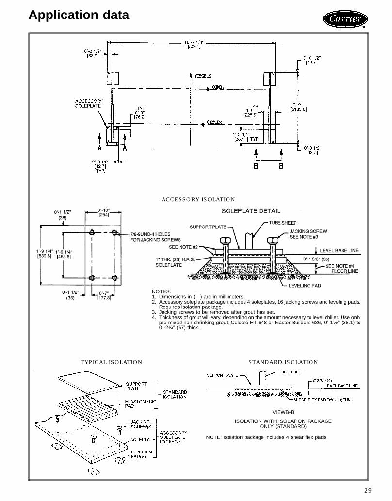
ACCESSORY ISOLATION
NOTES:1. Dimensions in ( ) are in millimeters.2. Accessory soleplate package includes 4 soleplates, 16 jacking screws and leveling pads.
Requires isolation package.3. Jacking screws to be removed after grout has set.4. Thickness of grout will vary, depending on the amount necessary to level chiller. Use only
pre-mixed non-shrinking grout, Celcote HT-648 or Master Builders 636, 08-11⁄29 (38.1) to08-21⁄49 (57) thick.
TYPICAL ISOLATION STANDARD ISOLATION
VIEWB-B
ISOLATION WITH ISOLATION PACKAGEONLY (STANDARD)
NOTE: Isolation package includes 4 shear flex pads.
29

Application data (cont)
NOZZLE ARRANGEMENTS
COOLER WATERBOXES
PASS IN OUT ARRANGEMENT CODE
18 5 A5 8 B
27 9 C4 6 D
37 6 E4 9 F
CONDENSER WATERBOXES
PASS IN OUT ARRANGEMENT CODE
111 2 P2 11 Q
210 12 R1 3 S
310 3 T1 12 U
WATERBOX NOZZLE SIZES
FRAME PASSNOMINAL PIPE SIZE (in.) ACTUAL PIPE ID (in.)
Cooler Condenser Cooler Condenser
61 10 10 10.020 10.0202 8 8 7.981 7.9813 6 6 6.065 6.065
LEGENDID — Inside Diameter
30

Vent and drain connectionsWith the exception of the cooler vent connection, locatedin the waterbox shell, all vents and drain connections arefound on the waterbox covers. Connection size is 3⁄4-in. FPT.Provide high points of the machine piping system with
vents and the low points with drains. If shutoff valves areprovided in the main water pipes near the unit, a minimalamount of system water is lost when the heat exchangersare drained. This reduces the time required for drainage andsaves on the cost of re-treating the system water.It is recommended that pressure gages be provided at
points of entering and leaving water to measure pressuredrop through the heat exchanger. Gages may be installedas shown in Pressure Gage Location table. Pressure gagesinstalled at the vent and drain connections do not includenozzle pressure losses.Use a reliable manometer to measure pressure differen-
tial when determining water flow. Regular gages are insen-sitive and do not provide accurate measurement of flowconditions.
PRESSURE GAGE LOCATION
NUMBEROF PASSES
GAGE LOCATION(Cooler or Condenser)
1 or 3 One gage in each waterbox2 Two gages in waterbox with nozzles
Range of applicationThe 19XT chiller is designed for standard water chilling ap-plications 300 to 550 tons (1055 to 1934 kW).
ASME stampingAll 19XT heat exchangers are constructed in accordancewith ASHRAE (American Society of Heating, Refrigera-tion, and Air Conditioning Engineers) 15 Safety Code forMechanical Refrigeration (latest edition). This code, in turn,requires conformance with ASME (American Society of Me-chanical Engineers) Code for Unfired Pressure Vessels wher-ever applicable.Each heat exchanger is ASME ‘U’ stamped on the refrig-
erant side of each vessel.
Relief valve discharge pipe sizingThe 19XT is equipped with 3 relief valves: 2 relief valvesare located on all 19XT condensers; 1 relief valve is locatedon all 19XT coolers. The condenser relief valves include atransfer valve.Relief-valve discharge piping size should be calculated per
the current version of the ASHRAE 15, latest edition, codeusing the tabulated C factors for each vessel shown below:
VESSEL VESSELSIZE
RELIEF VALVE SIZE(in. FPT)
C FACTOR(lb air/Min)
Cooler 60-63 11⁄4 74.7Condenser 60-63 11⁄4 69.9
Carrier further recommends that an oxygen sensor beinstalled to protect personnel. Sensor should be able to sensethe depletion or displacement of oxygen in the machineroom below 19.5% volume oxygen per ASHRAE 15, lat-est edition.
Design pressuresDesign and test pressures for 19XT heat exchangers arelisted below.
DESIGN AND TEST PRESSURES
PRESSURESSHELL SIDE(Refrigerant)
STANDARDTUBE SIDE(Water)
OPTIONALTUBE SIDE(Water)
psi kPa psi kPa psi kPaDesign 225 1551 150 1034 300 2068Hydrostatic Test — — 225 1551 450 3103Nitrogen/Helium Test 282 1944 — — — —
HEAT EXCHANGER MATERIAL SPECIFICATIONS
ITEM MATERIAL SPECIFICATIONShellTube Sheet
HR SteelHR Steel
ASME SA516 GR .70ASME SA516 GR .70
Cooler Waterbox Cover HR Steel ASME SA516 GR .70Cooler Waterbox Shell HR Steel ASME SA675 GR .60Condenser Waterbox HR Steel ASME SA516 GR. 70Tubes Finned Copper ASME SB359Discharge/Suction Steel ASME SA105
31
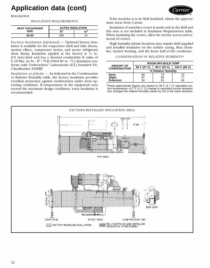
Application data (cont)Insulation
INSULATION REQUIREMENTS
HEAT EXCHANGERSIZE
EXTRA INSULATIONft2 m2
60-63 250 24
Factory insulation (optional) — Optional factory insu-lation is available for the evaporator shell and tube sheets,suction elbow, compressor motor, and motor refrigerantdrain line(s). Insulation applied at the factory is 3⁄4 in.(19 mm) thick and has a thermal conductivity K value of0.28 Btu • in/hr • ft2 • °F (0.0404W/m • °C). Insulation con-forms with Underwriters’ Laboratories (UL) Standard 94,Classification 94HBF.Insulation at jobsite — As indicated in the Condensationvs Relative Humidity table, the factory insulation providesexcellent protection against condensation under most op-erating conditions. If temperatures in the equipment areaexceed the maximum design conditions, extra insulation isrecommended.
If the machine is to be field insulated, obtain the approxi-mate areas from Carrier.Insulation of waterbox covers is made only in the field and
this area is not included in Insulation Requirements table.When insulating the covers, allow for service access and re-moval of covers.High humidity jobsite locations may require field supplied
and installed insulation on the turbine casing, float cham-ber, suction housing, and the lower half of the condenser.
CONDENSATION VS RELATIVE HUMIDITY*
AMOUNT OFCONDENSATION
ROOM DRY-BULB TEMP80 F (27 C) 90 F (32 C) 100 F (38 C)
% Relative HumidityNone 80 76 70Slight 87 84 77Extensive 94 91 84
*These approximate figures are based on 35 F (1.7 C) saturated suc-tion temperature. A 2° F (1.1° C) change in saturated suction tempera-ture changes the relative humidity values by 1% in the same direction.
FACTORY-INSTALLED INSULATION AREA
32

Guide specifications
Packaged Hermetic Centrifugal Liquid ChillerSize Range: 300 to 550 Tons (1055 to 1934 kW)
HFC-134aCarrier Model Number: 19XTPart 1 — General1.01 SYSTEM DESCRIPTIONA. Microprocessor-controlled liquid chiller shall utilize a
single stage, semi-hermetic centrifugal compressorusing refrigerant HFC-134a. Chillers using CFC re-frigerants such as CFC-11, 12, or 500 shall not beacceptable.If a manufacturer proposes a liquid chiller utilizingHCFC-123 refrigerant, then the manufacturer shallinclude in the chiller price:1. A vapor activated alarm system consisting of all
alarms, sensors, safeties, and ventilation equip-ment as required by ANSI/ASHRAE Standard 15Safety Code for Mechanical Refrigeration (latestedition) with the quotation. System shall be ca-pable of responding to HCFC-123 levels of10 ppm Allowable Exposure Limit (AEL).
2. External refrigerant storage tank and pumpout unit.3. High efficiency purge unit.4. Back-up relief valve to rupture disk.5. Chiller pressurizing system to prevent leakage of
noncondensables into chiller during shutdownperiods.
6. Plant room ventilation.1.02 QUALITY ASSURANCEA. Chiller performance shall be rated in accordance with
ARI Standard 550 (latest edition).B. Equipment and installation shall be in compliance with
ANSI/ASHRAE 15 (latest edition).C. Cooler and condenser shall include ASME ‘‘U’’ stamp
and nameplate certifying compliance with ASME Sec-tion VIII, Division 1 code for unfired pressure vessels.‘‘A manufacturer’s data report is required to verifypressure vessel construction adherence to ASMEvessel construction requirements. Form U-1 or U-3as required per ASME code rules is to be furnishedto the owner. The U-Form must be signed by aqualified inspector, holding a National Board Com-mission, certifying that construction conforms tothe latest ASME Code Section VIII, Div. 1 for pres-sure vessels. The ASME symbol ‘‘U’’ or ‘‘UM’’ mustalso be stamped on the heat exchanger. Vessels spe-cifically exempted from the Scope of the Code mustcome with material, test, and construction methodscertification and detailed documents similar to ASMEU-1; further, these must be signed by an officer ofthe company.’’
D. Chiller shall be manufactured in a facility which hasbeen registered by Underwriters’ Laboratories, Inc.(UL) to the International Organization for Standard-ization ISO 9000 Series Standards for quality.
E. Chiller shall be designed and constructed to meet ULand UL of Canada requirements and have labels ap-propriately affixed.
F. Compressor impellers shall be dynamically balancedand over speed tested by the manufacturer at a mini-
mum of 120% design operating speed. Each com-pressor assembly shall undergo a mechanical run-intest to verify vibration levels and oil pressures and tem-peratures are within acceptable limits. Each compres-sor assembly shall be pneumatically proof tested at aminimum 282 psig (1944 kPa) and leak tested with anitrogen/helium gas mixture at 225 psig (1551 kPa).
G. Both cooler and condenser shall be proof tested at282 psig (1944 kPa) on the refrigerant side and leaktested with a nitrogen/helium gas mixture at 225 psig(1551 kPa). The water side of each heat exchangershall be hydrostatically tested at 1.5 times rated work-ing pressure.
H. The entire chiller assembly shall be leak tested with anitrogen/helium gas mixture at 282 psig (1944 kPa).
I. Prior to shipment the chiller automated controls testshall be executed to check for proper wiring and en-sure correct controls operation.
J. On chillers with unit mounted compressor motor start-ers, chiller and starter shall be factory wired and testedtogether to verify proper starter operation prior toshipment.
1.03 DELIVERY, STORAGE AND HANDLINGA. Unit shall be stored and handled in accordance with
manufacturer’s instructions.B. Unit shall be shipped with all refrigerant piping and
control wiring factory installed.C. Unit shall be shipped charged with oil and refrigerant
HFC-134a or a nitrogen holding charge as specifiedon the equipment schedule.
D. Unit shall be shipped with firmly attached labels thatindicate name of manufacturer, chiller model number,chiller serial number, and refrigerant used.
1.04 WARRANTYWarranty shall include parts and labor for one yearafter start up or 18 months from shipment, which-ever occurs first.
Part 2 — Products2.01 EQUIPMENTA. General:
Factory assembled, single piece, liquid chiller shall con-sist of compressor, motor, lubrication system, cooler,condenser, initial oil and refrigerant operating charges,microprocessor control system and documentation re-quired prior to start-up. An optional compressor mo-tor starter can be mounted on the chiller, wired, andtested by the chiller manufacturer.
B. Compressor:1. One centrifugal compressor of the high perfor-
mance, single-stage type. Connections to thecompressor casing shall use O-rings instead ofgaskets to reduce the occurrence of refrigerantleakage.
2. The open type impeller with machined shroudcontours and impeller diameter optimize eachcompressor efficiency for each specifiedapplication.
33

Guide specifications (cont)
3. A tunnel diffuser shall provide a highly efficientcontrolled diffusion ratio by means of individuallycontoured, machined-in channels of circular crosssection.
4. Compressor, motor, and transmission shall be her-metically sealed into a common assembly and ar-ranged for easy field servicing. Internal compres-sor parts are accessible for servicingwithout removingthe compressor base from the chiller. Connec-tions to the compressor shall be flanged or boltedfor easy disassembly.
5. The compressor shall incorporate a two phase flowturbine expander energy reclaim system to re-cover energy otherwise lost in the expansion por-tion of the vapor compression cycle. The turbinewheel shall be attached to themotor shaft to supple-ment energy furnished by the motor.
6. Journal bearings shall be of the steel-backed, bab-bitt lined type.
7. The high speed shaft thrust bearing shall be of thetilting pad, multi-shoe, Kingsbury type with indi-vidually replaceable shoes. The low speed shaftthrust bearing shall be of the tapered land type.
8. Transmission shall be single ratio, single helical,parallel shaft speed increaser. Gears shall conformto AGMA Standard 421.
9. The compressor design shall include a balancingpiston to offset impeller thrust forces. The gearthrust load shall act opposite to impeller thrustloads.
10. The variable inlet guide vanes at the inlet to theimpeller shall provide capacity modulation from100% to 15% capacity, with 2.5 F (1.38 C) dropin entering condenser water temperature per 10%capacity reduction, while also providing pre-whirlof the refrigerant vapor entering the impeller formore efficient compression at all loads.
11. Compressor shall be provided with a factory in-stalled lubrication system to deliver oil under pres-sure to bearings and transmission. Included in thesystem shall be:a. Hermetic motor-driven oil pump with factoryinstalled motor contactor with overloadprotection.
b. Refrigerant-cooled oil cooler.c. Oil pressure regulator.d. Twenty-micron oil filter with isolation valvesto allow filter change without removal of re-frigerant charge.
e. Oil sump heater [115/230 v, 50 or 60 Hz]controlled from unit microprocessor.
f. Oil reservoir temperature sensor with maincontrol center digital readout.
g. Oil pump and motor for 200-240, 380-480,or 507-619 v, 3 ph, 60 Hz power source,or 220-240, 346-440 v, 3 ph, 50 Hz powersource.
h. When factory mounted compressor motorstarter is provided, all wiring to oil pump, oil
heater, and controls shall be prewired in thefactory and power shall be applied to checkproper operation prior to shipment.
12. Compressor shall be fully field serviceable. Com-pressors which must be removed and returnedto the factory for service shall be unacceptable.
13. Acoustical attenuation shall be provided as re-quired, to achieve a maximum (full load or partload) sound level of [ ] dBA, measured perARI Standard 575 (latest edition). Attenuationshall be designed to be easily removed andreinstalled.
C. Motor:1. Compressor motor shall be of the hermetic, liquid
refrigerant cooled, squirrel cage, induction type suit-able for voltage shown on the equipment sched-ule. If open motors are used in place of refrigerantcooled motors, the manufacturer shall supply acurve of motor heat loss as a function of load toallow calculation of the additional ventilation or airconditioning load generated from the motor heatrejection. In addition, a mechanical room safetyalarm, wiring, and chiller emergency shut downshall be included to prevent chiller operation if ma-chine room temperature exceeds 104 F (40 C).
2. Motor design speed shall be 3550 rpm (60 Hz) or2950 rpm (50 Hz).
3. Motors shall be suitable for operation in a refrig-erant atmosphere and shall be cooled by atomizedrefrigerant in contact with the motor windings.
4. Motor stator shall be arranged for service or re-moval with only minor compressor disassembly.
5. Full load operation of the motor shall not exceednameplate rating.
6. One motor winding (with one spare) temperaturesensor shall be provided.
7. Low voltage motors (600 v or less) shall be suit-able for connection to wye-delta type reduced in-rush starters or solid-state type reduced voltagestarters.
8. Should the mechanical contractor choose to pro-vide a chiller with an open motor instead of thespecified semi-hermetic motor, the contractor shalleither:Supply additional ventilation to maintain a maxi-mum mechanical room temperature of 104 F(40 C). Additional ventilation requirements shallbe calculated as follows:Cfm = (Full load motor kW) (0.05) (3413)
/(104 – 95) (1.08)Cfm = (FLkW motor) (17.6)or, if the mechanical room is air conditioned, themechanical contractor shall install additional cool-ing equipment to dissipate the motor heat as perthe following formula:Btuh = (FLkW motor) (0.05) (3413)Btuh = (FLkW motor) (171)and, alternatelyTons = Btuh/12,000
34

In either case, the additional piping, valves, air-handling equipment, insulation, wiring, switch-gear changes, ductwork, and coordination withother trades shall be the responsibility of the me-chanical contractor. Shop drawings reflecting anychanges to the design shall be included in the sub-mittal, and incorporated into the final as-built draw-ings for the project.Also, if an open motor is provided, a mechanicalroom thermostat shall be installed and set at104 F (40 C). If this temperature is exceeded, thechillers shall shut down and an alarm signal shallbe generated to the central Energy ManagementSystem (EMS) display module prompting the serv-ice personnel to diagnose and repair the cause ofthe over temperature condition. The mechanicalcontractor shall be responsible for all changes tothe design, including coordination with tempera-ture control, electrical, and other trades.In addition, the electrical power consumption ofany auxiliary ventilation and/or mechanical cool-ing required to maintain the mechanical room con-ditions stated above shall be considered in the de-termination of conformance to the scheduled chillerenergy efficiency requirement.
D. Cooler and Condenser:1. Cooler and condenser shall be of shell and tube
type construction, each in separate shells. Unitsshall be fabricated with high-performance tub-ing, steel shell and tube sheets with fabricatedsteel waterboxes. Waterboxes shall be nozzle-in-head type with stubout nozzles having Victaulicgrooves to allow for use of Victaulic couplings.
2. Tubing shall be copper, high-efficiency type, withintegral internal and external enhancement. Tubesshall be nominal 3⁄4-in. OD with nominal wallthickness of 0.025 in. measured at the root ofthe fin. Tubes shall be rolled into tube sheets andshall be individually replaceable. Tube sheet holesshall be double grooved for joint structural integ-rity. Intermediate support sheet spacing shall notexceed 36 in. (914 mm).
3. Waterboxes and nozzle connections shall be de-signed for 150 psig (1034 kPa) minimum work-ing pressure unless otherwise noted. Nozzles shouldhave grooves to allow use of Victaulic couplings.
4. The tube sheets of the cooler and condenser shallbe bolted together to allow for field disassemblyand reassembly.
5. The vessel shall display an ASME nameplatewhich shows the pressure and temperature dataand the ‘‘U’’ stamp for ASME Section VIII, Di-vision 1. A pressure relief valve shall be installedon each heat exchanger.
6. Waterboxes shall have vents, drains and coversto permit tube cleaning within the space shownon the drawings. A thermistor type temperaturesensor shall be factory installed in each waternozzle.
7. Cooler shall be designed to prevent liquid refrig-erant from entering the compressor. Devices thatintroduce pressure losses (such as mist elimina-tors) shall not be acceptable because they are sub-ject to structural failures that can result in exten-sive compressor damage.
8. Tubes shall be individually replaceable from ei-ther end of the heat exchanger without affectingthe strength and durability of the tube sheet andwithout causing leakage in adjacent tubes.
9. The condenser shell shall include a sensible sub-cooler which cools the condensed liquid refrig-erant to a reduced temperature, thereby increas-ing the refrigeration cycle efficiency.
10. Optional compressor discharge isolation valve andliquid line ball shall be factory installed to allowisolation of the refrigerant charge in the con-denser for servicing the compressor.
E. Refrigerant Flow Control:To improve part load efficiency, liquid refrigerant shallbe metered from the condenser to the cooler using afloat-type metering valve to maintain the properliquid level of refrigerant in the heat exchangers un-der both full and part load operating conditions. Bymaintaining a liquid seal at the flow valve, bypassedhot gas from the condenser to the cooler is elimi-nated. The float valve chamber shall have a boltedaccess cover to allow field inspection and the floatvalve shall be field serviceable. Fixed orifices shall beunacceptable.
F. Controls, Safeties and Diagnostics:1. Controls:
a. The chiller shall be provided with a factoryinstalled and wired microprocessor controlcenter with individually replaceable modularcomponent construction. Components in-cluded shall be the main processor/input-output module, power supply, starter man-agementmodule (located in the starter cabinet),relay board, and temperature and pressure(thermistor and transducer) sensors. An op-tional input module (8 input channels) can befactory or field installed. The control centerincludes a 16 line by 40 character liquid crys-tal display, 4 function keys, stop button, andalarm light. The microprocessor can be con-figured for either English or SI units.The chiller control system shall have the abil-ity to interface and communicate directly tothe building control system without the useof additional field-installed hardware or soft-ware. Additional hardware will be necessaryif the building control system is not CarrierComfort Network (CCN).
35

Guide specifications (cont)
b. The default standard display screen shall si-multaneously indicate the following minimuminformation:1) date and time of day2) 24 character primary system status
message3) 24 character secondary status message4) chiller operating hours5) entering chilled water temperature6) leaving chilled water temperature7) evaporator refrigerant temperature8) entering condenser water temperature9) leaving condenser water temperature10) condenser refrigerant temperature11) oil supply pressure12) oil sump temperature13) percent motor Rated Load Amps (RLA)The default screen shall be displayed if thereis no manual activity at the control consolefor 15 minutes.
c. The 4 function keys shall be software drivenwithin the Status, Schedule, Set Point andService menu structures (as described below).1) Status Function:
In addition to the default screen, statusscreens shall be accessible to view the sta-tus of every point monitored by the con-trol center including:• evaporator pressure• condenser pressure• bearing oil supply temperature• compressor discharge temperature• motor winding temperature• number of compressor starts• control point settings• discrete output status of various devices• compressor motor starter status• optional spare input channels(16 maximum)
2) Schedule Function:The chiller controls shall be configurablefor manual or automatic start-up and shut-down. In automatic operation mode, thecontrols shall be capable of automaticallystarting and stopping the chiller accord-ing to a stored user programmable occu-pancy schedule. The controls shall includebuilt-in provisions for accepting a mini-mum of two 365-day occupancy sched-ules. Each schedule shall allow a minimumof 8 separate occupied/unoccupied peri-ods, any or all of which can be scheduledby individual day for any or all days of theweek, with a separate schedule for holi-days. Schedules shall allow specificationof Daylight savings start/end and up to18 user-defined holidays up to one yearin advance (month, day, and duration indays). Display of the occupancy schedulesshall be viewable on the LCD screen. Eachschedule shall provide a means of config-uring an occupancy timed override to per-mit a ‘‘one time extension’’ of an occu-pied period on the configured day. The
controls shall also provide for chiller start-upand shutdown via remote contact closurefrom a customer supplied device or froma building management system softwarecommand.
3) Set Point Function:The controls shall provide the capabilityto view and change the leaving chilled wa-ter set point, entering chilled water setpoint, and demand limit set point at any-time during chiller operating or shutdownperiods. The controls shall allow for thespecification of capacity control by eitherleaving chilled water or entering chilledwater.
4) Service Function:The controls shall provide a password pro-tected service function which allows au-thorized individuals to:• View an alarm history file which shallcontain the last 25 alarm/alert mes-sages with time and date stamp. Thesemessages shall be displayed in text form,not codes
• Execute a chiller controls test functionfor quick identification of malfunction-ing components
• View/modify chiller configuration• View/modify chiller occupancy periods• View/modify schedule holiday periods• View/modify schedule override periods• View/modify system time and date
d. Capacity control shall be by means of a vari-able inlet guide vanes located at the impellerinlet. Load modulation shall be from 100%to 15% of compressor full load under normalARI conditions without the use of hot gas by-pass. The guide vanes are precisely posi-tioned by aPID (proportional-integral-derivative)control algorithm to ensure precise control(±.5° F [±.3° C]) of desired chilled water tem-perature without hunting or overshooting theset point.
e. The microprocessor control system shall in-clude a programmed sequence to meet pre-lube needs prior to machine start-up and dur-ing coast down after machine stop. Themicroprocessor shall automatically activateand interlock the chilled water pump, con-denser water pump, and cooling tower fansupon chiller activation.
f. Upon request to start the compressor, the con-trol system shall start the chilled water pump,condenser water pumps and tower fans andverify that flows have been established. Thecontroller shall then compare the entering/leaving chilled water temperature with thechilled water set point. If the chilled watertemperature is less than the chilled water setpoint, the control system shall shut down thecondenser water pump and wait for the cool-ing load to be established.
36

g. A user-configurable ramp loading rate, effec-tive during the chilled water temperature pull-down period, shall control the rate of guidevane opening to prevent a rapid increase incompressor power consumption. The con-trols shall allow configuration of the ramploading rate in either degrees/minute of chilledwater temperature pulldown or percent mo-tor amps/minute. During the ramp loadingperiod, a message shall be displayed inform-ing the operator that the chiller is operatingin ramp loading mode.
h. The control system shall include 2 compres-sor cycle timers to protect the motor fromrapid cycling, a 15 minute minimum start-to-start timer, and a 1 minute minimum stop-to-start timer. In addition the compressor shallbe inhibited from restarting if more than8 manual starts within a 12 hour period haveoccurred.
i. The control system shall automatically cyclethe compressor off to minimize energy usagewhenever the leaving chilled water tempera-ture is 5° F (3° C) below the desired chilledwater set point. The chilled water pump shallremain on and when the leaving chilled wa-ter temperature rises above the set point bya user-configured amount, the compressorshall automatically restart. During the shut-down period, a message shall be displayedinforming the operator a recycle restart ispending.
j. The control system shall monitor line voltageand if loss of voltage, high or low line volt-age, or single cycle dropout is sensed, thechiller shall shut down. Upon restoration ofline voltage, if the auto-restart after powerfailure algorithm is enabled, the chiller shallautomatically resume the mode of operationfunctioning prior to shutdown.
k. The control center shall allow reset of thechilled water temperature set point based onany one of the following criteria:• Chilled water reset based on an external 4to 20 mA signal.
• Chilled water reset based on a remote tem-perature sensor (such as outdoor air).
• Chilled water reset based on water tem-perature rise across the evaporator.
When reset is active, a message shall be dis-played indicating the type reset in effect.
l. The control center shall limit amp draw ofthe compressor to the rated load amps or toa lower value based on one of the followingcriteria:• Demand limit based on a user input rang-ing from 40% to 100% of compressor ratedload amps
• Demand limit based on external 4 to20 mA signal.
When demand limit is active a message shallbe displayed indicating the source of the de-mand signal.
m. The controls shall be capable of being con-figured to soft stop the compressor. Whenthe stop button is pressed or remote contactsopen with this feature active, the guide vanesshall close to a configured amperage level andthe machine shall then shut down. The dis-play shall indicate ‘‘shutdown in progress.’’
2. Safeties:a. Unit shall automatically shut down when any
of the following conditions occur: (Each ofthese protective limits shall require manualreset and cause an alarm message to be dis-played on the LCD screen, informing the op-erator of the shutdown cause.)1) Motor overcurrent2) Over voltage*3) Under voltage*4) Single cycle dropout*5) Bearing oil high temperature6) Low evaporator refrigerant temperature7) High condenser pressure8) High motor temperature9) High compressor discharge temperature10) Low oil pressure11) Prolonged surge12) Loss of cooler water flow13) Loss of condenser water flow14) Starter fault
*Shall not require manual reset or causean alarm if auto-restart after power fail-ure is enabled.
b. The control system shall detect conditionswhich approach protective limits and take self-corrective action prior to an alarm occurring.The system shall automatically reduce chillercapacity when any of the following param-eters are outside their normal operating range:• high-condenser pressure• high-motor temperature• low evaporator refrigerant temperature• high motor ampsDuring the capacity override period, a pre-alarm (alert) message shall be displayed in-forming the operator which condition is caus-ing the capacity override. Once the conditionis again within acceptable limits, the overridecondition shall be terminated and the chillershall revert to normal chilled water control.If during either condition the protective limitis reached, the chiller shall shut down, analarm shall be generated, and a text messageshall be displayed informing the operatorwhich condition caused the shut down andalarm.
37
Guide specifications (cont)
3. Diagnostics and Service:a. The control system shall execute a series of
prestart checks whenever a start commandis received to determine if pressures, tem-peratures, and timers are within pre-start lim-its, thereby allowing start-up to proceed. Ifany of the limits are exceeded, a text alertmessage will be displayed informing the op-erator of the cause of the pre-start alert.
b. A self diagnostic controls test shall be an in-tegral part of the control system to allow quickidentification of malfunctioning components.Once the controls test has been initiated, allpressure and temperature sensors shall bechecked to ensure they are within normal op-erating range. A pump test shall automati-cally energize the chilled water pump, con-denser water pump, and oil pump. The controlsystem shall confirm that water flow and oilpressure have been established and requireoperator confirmation before proceeding tothe next test. A guide vane actuator test shallopen and close the guide vanes to check forproper operation prior to proceeding to thenext test. The operator manually acknowl-edges proper guide vane operation prior toproceeding to the next test.
c. In addition to the automated controls test, thecontrols shall provide amanual test which per-mits selection and testing of individual con-trol components and inputs. A thermistor testand transducer test shall display on the LCDscreen the actual reading of each transducerand each thermistor installed on the chiller.
d. All sensors shall have quick disconnects toallow replacement of the sensor without re-placement of the entire sensor wire. Pressuretransducers shall be capable of field calibra-tion to ensure accurate readings and to avoidunnecessary transducer replacement. Trans-ducers shall be serviceable without the needfor refrigerant charge removal or isolation.
4. Building Control System Interface:The chiller control system shall have the ability tointerface and communicate directly to the build-ing control system without the use of additionalfield installed hardware and software. The build-ing control system and the centrifugal chiller mustbe supplied by the same manufacturer. If differentbuilding control and chiller suppliers are chosenthe chiller shall be supplied with a Dataport mod-ule which shall translate the information in thechiller microprocessor to an ASCII stream of datawhich can be read by any manufacturer’s buildingmanagement control system.
5. Multiple Chiller ControlThe chiller controls shall be supplied as standardwith a two chiller lead/lag and a third chiller standbysystem. The control system shall automatically startand stop a lag or second chiller on a two chiller
system. If one of the two chillers on line goes intoa fault mode, the third standby chiller shall be au-tomatically started. The two chiller lead/lag sys-tem shall allow manual rotation of the lead chiller,include load balancing if configured, and a stag-gered restart of the chillers after a power failure.For systems with more than two operational chill-ers, a Chillervisor System Manager (CSM) moduleshall be field installed in the control center of oneof the chillers. This control system can automati-cally control up to 8 chillers in the same plant room.If desired, other components of the chilled waterplant, such as cooling towers, pumps, and valvescan be controlled by additional hardware and soft-ware supplied by the chiller manufacturer.
G. Optional Low Voltage Unit Mounted Starter:An optional reduced voltage wye-delta or solid-statestarter shall be supplied. The compressor motor startershall be factory mounted, wired and tested prior toshipment by the chiller manufacturer. Customer elec-trical connection for compressor motor power shallbe limited to main power leads to the starter, wiringof the cooler and condenser flow switches to the chillercontrol circuit, and wiring water pumps and tower fansto the chiller control circuit. Included in the UL andCSA approved starters are:1. NEMA 1 enclosure with integral fan cooling and
lockable hinged doors.2. Main power disconnect (non-fused type).3. Starter Management Module (SMM) which com-
municates with the chiller control system to per-form starting and stopping of the chiller, waterpumps, and tower fans, as well as monitoringstarter operation. Included in this module is asingle cycle dropout protection.
4. Solid-state, 3-phase, overload relay with manualreset.
5. 2 kva control/oil heater transformer.6. Branch circuit breaker for oil pump.7. Branch circuit breaker for control power and oil
heater.8. 5 pilot relays for control of chilled water pump,
condenser water pump, tower fan, customer re-mote alarm, and main power disconnect shunttrip.
9. Optional solid-state starter shall provide steplesscompressor motor acceleration and limit motorinrush current to 150-300% of compressor mo-tor rated load amps. The starter shall include 6Silicon Control Rectifiers (SCR) with integrallymounted bypass contactors to provide SCR by-pass once the motor has achieved full voltageand speed. The starter shall also include auto-matic acceleration kick circuitry which monitorsmotor current to sense when the inrush currentsubsides and automatically ramps voltage up ata quicker rate to eliminate the instability whichoccurs at the break-away torque point.
38

Solid-state starter shall also include the followingstandard features:a. Current imbalance detector which monitors3-phase motor current to provide the follow-ing protection:1) Phase loss2) Phase reversal3) Phase imbalance4) Ground fault5) Shorted SCR6) Current flow while stopped protection
b. Diagnostic LED’s shall be provided toindicate:1) Starter on2) Run (up to voltage)3) Phase correct4) Over-temperature fault5) SCR gates energized6) Ground fault7) Current imbalance fault8) Shorted SCR
10. I2T fuses that protect the solid-state circuitry at200,000 amp interrupting capacity.
H. Electrical Requirements:1. Electrical contractor shall supply and install main
electrical power line, disconnect switches, circuitbreakers, and electrical protection devices per lo-cal code requirements and as indicated necessaryby the chiller manufacturer.
2. Electrical contractor shall wire thewater flow switchesto the chiller control circuit to ensure that chillerwill not operate until flows are established andmaintained.
3. Electrical contractor shall wire the chilled waterpump, condenser water pump, and tower fan con-trol circuit to the chiller control circuit.
4. Electrical contractor shall supply and install elec-trical wiring and devices required to interface thechiller controls with the building control system ifapplicable.
5. Electrical power shall be supplied to the unit at thevoltage, phase, and frequency listed in the equip-ment schedule.
I. Piping Requirements — Instrumentation andSafeties:1. Mechanical contractor shall supply and install pres-
sure gages in readily accessible locations in pipingadjacent to the chiller such that they can be easilyread from a standing position on the floor. Gagesshall be Marsh Master or equal with 41⁄2 in. nomi-nal diameter face. Scale range shall be such thatdesign values shall be indicated at approximatelymid-scale.Gages shall be installed in the entering and leav-ing water lines of the cooler and condenser.
2. Mechanical contractor shall supply and install flowdetection devices (United Electric 24-013H2012Ror equal) in chilled water and condenser water pip-ing. Switches shall make contact when flow is es-tablished. Flow switches shall be installed in hori-zontal runs at least 5 pipe diameters downstreamfrom any bend or tee.
J. Insulation:1. Chilled water piping and cooler waterboxes shall
be insulated by the mechanical contractor.2. Chiller shall be factory insulated or chiller
shall be insulated at the jobsite per manufacturer’sinstructions.
3. Chiller insulation shall be 3⁄4 in. (19 mm) thick andshall have a thermal conductivity not exceeding0.28 Btu•in./h•ft2•oF (0.0404 W/m•oC) and shallconform toUL Standard 94, Classification 94HBF.
K. Vibration Isolation:Chiller manufacturer shall furnish neoprene isolatorpads for mounting equipment on a level concretesurface.
L. Start-up:1. The chiller manufacturer shall provide a factory-
trained representative, employed by the chillermanufacturer, to perform the start-up pro-cedures as outlined in the Start-up, Operation andMaintenance manual provided by the chillermanufacturer.
2. After the above services have been performed, thesame factory-trained representative shall be avail-able for a period of classroom instruction not toexceed 8 hours to instruct the owner’s personnelin the proper operation and maintenance of thechiller.
3. Manufacturer shall supply the following literature:a. Start-up, operation and maintenance
instructions.b. Installation instructions.c. Field wiring diagrams.d. One complete set of certified drawings.
M. Optional Storage Tank and Pumpout Unit:An optional freestanding refrigerant storage tank andpumpout unit shall be provided. The storage vesselsshall be designed per ASME Section VIII Division 1code with 300 psig (2068 kPa) design pressure. Doublerelief valves per ANSI/ASHRAE 15, latest edition,shall be provided. The tank shall include a liquid levelgage and pressure gage. The pumpout unit shall uti-lize a semi-hermetic reciprocating compressor withwater cooled condenser. Condenser water piping, 3phase motor power, and 115-volt control power shallbe installed at the jobsite by the installing contractor.
39

Carrier Corporation • Syracuse, New York 13221 1-95
Manufacturer reserves the right to discontinue, or change at any time, specifications or designs without notice and without incurring obligations.
Book 2Tab 5a
Page 40 Catalog No. 521-935 Printed in U.S.A. PC 211 Form 19XT-1PDReplaces: New