product 39sh,sv,sm,sr00-17 data - carrier · carrier 39s air handlers are rated in accordance with...
TRANSCRIPT
© Carrier Corporation 2015 Form 39S-4PD
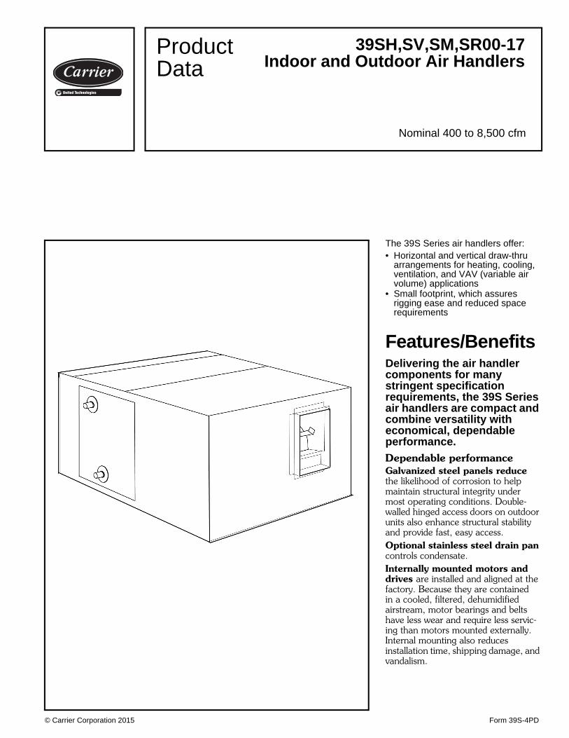
The 39S Series air handlers offer:• Horizontal and vertical draw-thru
arrangements for heating, cooling, ventilation, and VAV (variable air volume) applications
• Small footprint, which assures rigging ease and reduced space requirements
Features/BenefitsDelivering the air handler components for many stringent specification requirements, the 39S Series air handlers are compact and combine versatility with economical, dependable performance.Dependable performanceGalvanized steel panels reduce the likelihood of corrosion to help maintain structural integrity under most operating conditions. Double-walled hinged access doors on outdoor units also enhance structural stability and provide fast, easy access.Optional stainless steel drain pan controls condensate.Internally mounted motors and drives are installed and aligned at the factory. Because they are contained in a cooled, filtered, dehumidified airstream, motor bearings and belts have less wear and require less servic-ing than motors mounted externally. Internal mounting also reduces installation time, shipping damage, and vandalism.
39SH,SV,SM,SR00-17Indoor and Outdoor Air Handlers
Nominal 400 to 8,500 cfm
ProductData
a39-4062
2
Precision-balanced fan wheels limit vibration and reduce abnormal stress on bearings and other components.Motor start/stop station is an avail-able motor option that provides conve-nient motor control outside the unit cabinet.Fan bearings are rated at 200,000 hours average life.Mixing boxes and filter mixing boxes have parallel blades to provide thorough, efficient air mixing. Dampers are sectioned to prevent ex-cess blade warping and ensure tight closure.
EconomyFactory assembled, prealigned drives and fans eliminate field instal-lation expense, saving money.Small envelope size is easy to rig and ensures economical use of building space. Quicker, easier installation and set up reduce start-up costs.Entirely vertical option minimizes the unit footprint to maximize space in the mechanical room.Hinged access doors on outdoor, double wall units ease service and access as compared to fixed panels, saving time and money.
Coil flexibilityThe 39S units offer a wide selection of coils for cooling, heating, preheat
with cooling, or cooling with reheat application.Chilled water, DX (direct expan-sion), and steam coils are available for most product lines in both standard and high capacities while hot water coils are available in 1, 2, 4 and 6 rows for most product lines. The DX coils come equipped with factory-installed TXVs (thermostatic expansion valves) and nozzles.• Biflow TXVs for units under 5 tons
allow for use with heat pumps.• Heat pump kits are available for
units from 5 to 10 tons.Single circuit and face splits are also available.Electric heaters are available over a wide kilowatt range in a number of voltages.
AHRI certificationThe Air-Conditioning, Heating and Re-frigeration Institute (AHRI) is a volun-tary, nonprofit organization com-prised of the manufacturers of air con-ditioning, refrigeration, and heating products. More than 90% of the air conditioning and refrigeration machin-ery and components manufactured in the United States is produced by mem-bers of AHRI.
Carrier 39S air handlers are rated in accordance with AHRI Standard 430, which is the industry standard for central station air-handling units. Certi-fication by participating manufacturers of units within the scope of this pro-gram requires that the ratings and per-formance of any central station unit certified to AHRI be established in ac-cordance with the AHRI Standard.
The following items are not within the scope of the AHRI Central Station Air Handlers Certification program:• sound ratings• electric heating coil ratings
Features/Benefits (cont)
Table of contentsPage
Features/Benefits . . . . . . . . . . . . . . . . . . . . . . . . . . . . . . . . . . . . . . . . . . 1,2AHRI Certification . . . . . . . . . . . . . . . . . . . . . . . . . . . . . . . . . . . . . . . . . . . 2Model Number Nomenclature . . . . . . . . . . . . . . . . . . . . . . . . . . . . . . . . . . . 3Factory-Installed Options. . . . . . . . . . . . . . . . . . . . . . . . . . . . . . . . . . . . . . . 4Application Data . . . . . . . . . . . . . . . . . . . . . . . . . . . . . . . . . . . . . . . . . 5-12Selection Procedure . . . . . . . . . . . . . . . . . . . . . . . . . . . . . . . . . . . . . . 13,14Performance Data . . . . . . . . . . . . . . . . . . . . . . . . . . . . . . . . . . . . . . . 15-28Dimensions . . . . . . . . . . . . . . . . . . . . . . . . . . . . . . . . . . . . . . . . . . . . 29-46Physical Data . . . . . . . . . . . . . . . . . . . . . . . . . . . . . . . . . . . . . . . . . . . 47,48Guide Specifications . . . . . . . . . . . . . . . . . . . . . . . . . . . . . . . . . . . . . . 49-51

3
Model number nomenclature
a39-4120
Due to the complexity of the 39S model number, use the “verify model number” function in the AHUBuilder® software fora detailed model explanation.
LEGEND
*Contact your local Carrier representative for a list of availableunit arrangements.†See page 4 for a list of factory-installed options.**Unit shall be factory wired. Field must switch transformer tap(if provided) to 208v.
TXV — Thermostatic Expansion Valve

4
LEGEND
*Motor start/stop station is not available with electric heat on 39SH units or on any unit with 2-speed motors.†Plastic drain pan is standard on 39SH,SV02-09 units and not available on 39SH00,01,13,17 or 39SV13,17 units. **Stainless steel drain pan is not available on 39SV02-09 units.
Factory-installed optionsFilters — Two-in. throwaway filters are standard on all39S units. Two-in., MERV 7 pleated filters are also avail-able on all units for increased filtration flexibility.Insulation — The 39S unit has a minimum 3/4 in. insula-tion thickness. Several insulation options are availablealong with a double-wall finish in order to meet various job-site requirements.
INSULATION OPTIONS
*Registered trademark of Johns Manville, Inc.
NOTE: Dimensions indicate insulation thickness.
Electrical options — Junction boxes are standard on all39S air handlers. Motor start/stop stations are available onmost units for unit fan motor control.Drain pans — The 39S air handler offers a wide array ofdrain pan finishes. Plastic and galvanized coatings are of-fered as low-cost options. Stainless steel is also available,providing an easy-to-clean, corrosion resistant surface.
ITEM39S UNIT TYPE
SH SV SM SRMERV 7, 2 in. Pleated Filter X X X XThrowaway Filters for Face, Bypass, and Filter Sections X — — —Indoor Air Quality (IAQ) Insulation Std Std X XClosed Cell Insulation X X X XDouble Wall Insulation X X XMotor Start/Stop Station* X X X —Plastic Drain Pan† Std/— Std/X — —Stainless Steel Drain Pan** Std/X Std/X X XGalvanized Steel Drain Pan — Std/X Std Std
Std — Standard ItemX — Optional Item— — Unavailable ItemStd/— — Standard or Unavailable Item Depending on Unit SizeStd/X — Standard or Optional Item Depending on Unit Size
INSULATION TYPE39S UNIT TYPE
SH SV SM SRTuf-Skin® II* – – 3/4 in. 1 in.Exact-O-Kote® IAQ* 1 in. 1 in. 1 in. 1 in.Closed Cell 7/8 in. 7/8 in. 3/4 in. 7/8 in.Double Wall 1 in. 1 in. – 1 in.
Factory-installed options

5
Central station air handlerThe central station air handler is a heating, ventilating, orair-conditioning unit that is centrally located in, or on, abuilding or structure and from which air is distributed todesired areas through a system of ducts.
The 39S factory packaged unitIndividual components, such as fans, coils, and filters, areassembled at the factory.
Packaged equipment is less costly than field-fabricatedequipment and does not require assembly.
The basic air-handling unit consists of a fan section, coilsection, and filter. Other components, such as air-mixingboxes and damper sections, may also be provided.
Central station configurationsDraw-thru unitsHorizontal
Vertical (indoor unit only)
FansThe 39S central station air handlers use belt-driven centrif-ugal fans. A centrifugal fan is one in which the air flowsradially through the impeller. Centrifugal fans are classifiedaccording to fan wheel and blade construction. The 39Sfan has forward-curved blades.
Laws of fan performanceFan laws are used to predict fan performance under chang-ing operating conditions or by fan size. They are applicableto all types of fans.
The fan laws are stated below. The symbols used in theformulas represent the following variables:CFM — Volume rate of flow through the fan.RPM — Rotational speed of the impeller.P — Pressure developed by the fan.Hp — Horsepower input to the fan.D — Fan wheel diameter. The fan size number can be
used if it is proportional to the wheel diameter.W — Air density, varying directly as the barometric pres-
sure and inversely as the absolute temperature.Application of these laws is limited to cases where fans
are geometrically similar.
FAN LAWS
*Fan discharge may be horizontal or upblast.
VARIABLE CONSTANT LAW FORMULA
SPEED(RPM)
Air DensityFan SizeDistribution System
Airflow varies directly with the Speed.
Pressure varies as the square of the Speed.
Horsepower varies as the cube of the Speed.
FAN SIZE(D)
Air DensityTip Speed
Capacity and Horsepower vary as the square of the Fan Size.
Speed varies inversely as the Fan Size.
Pressure remains constant. P1 = P2
Air DensityWheel Speed
Capacity varies as the cube of the Size.
Pressure varies as the square of the Size.
Horsepower varies as the fifth power of the Size.
AIR DENSITY(W)
PressureFan SizeDistribution System
Speed, Capacity, and Horsepower vary inversely as the square root of Density.
AirflowFan SizeDistribution System
Pressure and Horsepower vary with Density.
Speed remains constant. RPM1 = RPM2
CFM1=
RPM1
CFM2 RPM2
P1= (RPM1)2
P2 RPM2
Hp1= (RPM1 )3
Hp2 RPM2
CFM1=
Hp1= (D1)2
CFM2 Hp2 D2
RPM1=
D2
RPM2 D1
CFM1= (D1)3
CFM2 D2
P1= (D1)2
P2 D2
Hp1= (D1)5
Hp2 D2
RPM1=
CFM1=
Hp1= (W2)1/2
RPM2 CFM2 Hp2 W1
P1=
Hp1=
W1
P2 Hp2 W2
Application data

6
Fan selection criteriaSystem requirements — The major factors that influ-ence fan selection are airflow, external static pressure, fanspeed, brake horsepower, and sound level. Additionalsystem considerations include the fan control method,overloading, and non-standard air density. Fan selectionfor air-conditioning service usually involves choosing thesmallest fan that provides an acceptable level of perfor-mance, efficiency, and quality.Pressure considerations — The static pressure is theresistance of the combined system apart from the fan.Contributors to static pressure include other componentsin the air handler, ductwork, and terminals. The staticpressure is dependent on the airflow through the system,which is determined by the air conditioning requirements.As shown in the second fan law in the table on the preced-ing page, the static pressure varies as the square of theairflow (cfm). This ratio between pressure and airflowdetermines the system curve for any air-handling system.
The static pressure used to select a fan should be thepressure calculated for the system at design airflow. If thestatic pressure is overestimated, the amount of increase inhorsepower and air volume depends upon the steepness ofthe fan curves in the area of selection.
With forward-curved (FC) fans, if the actual static pres-sure of the system is less than the design static pressure,the fan has a tendency to deliver more air and draw corre-spondingly higher bhp (kW of energy). This higher currentdraw may overload the motor and trip circuit breakers.This is a common occurrence when FC centrifugal fans areoperated before all the ductwork has been installed, orduring the pull-down load on a VAV (variable air volume)system.Stability — Fan operation is stable if it remains un-changed after a slight temporary disturbance, or if the fanoperation point shifts to another location on the fan curveafter a slight permanent disturbance. Fan operation isunstable if it fluctuates repeatedly or erratically. There are2 main types of unstable fan operation:System surge is a cycling increase and decrease in systemstatic pressure.Fan stall is the most common type of instability, and itoccurs with any type of centrifugal fan when the fan isstarved for air.
Normally, the rotation of the fan wheel forces the airthrough the blade passageway from the low pressure to thehigh pressure side of the fan. If the airflow is restricted toomuch, however, there is not enough air to fill the spacebetween the blades and the air distribution between theblades becomes uneven and erratic. Air can flow back-wards through the wheel and the noise level is substantiallyincreased. If the fan runs in this condition for a long time,wheel failure is likely to occur.
For a given speed, the operating point where a fan stallsis a function of the wheel geometry and wheel speed. Ingeneral, the stall point is within the range of 15 to 25% ofthe airflow obtained at free delivery.Stability and VAV applications — Special consider-ations must be made for VAV systems. While the initial fan
selection may be acceptable, its operating point could shiftto a point of stall at minimum airflow and pressure condi-tions. The typical minimum airflow is half of the designcooling airflow, which is also often equal to the heatingairflow. To determine and plot the minimum airflow versusstatic pressure, use the following equation. This equationsolves for the static pressure at a specific airflow based ona minimum static pressure set point:
The table below illustrates a system with an airfoil fanwheel at a cooling design of 15,000 cfm and a systemstatic pressure of 4 in. wg. The minimum airflow is7,500 cfm with a minimum system static pressure set pointof 2 in. wg. The minimum static set point is based onzero airflow and does not coincide with the mini-mum design airflow.Example:
As shown on the highlighted VAV curve, the minimumairflow and static pressure (MP) are both well within the ac-ceptable operating conditions of the fan.
( ( CFM1 ) 2X (SPDESIGN – SPMIN) ) + SPMIN = SP1
CFMDESIGN
( ( 7,500 ) 2X (4 – 2) ) + 2 = 2.50 in. wg
15,000
CFM — Airflow in Cubic Feet Per MinuteSP — Static Pressure
% AIRFLOW CFM SYSTEM AND FAN STATIC PRESSURE(in. wg)
100 15,000 4.0090 13,500 3.6280 12,000 3.2870 10,500 2.9860 9,000 2.7250 7,500 2.50
0 2 4 6 8 10 12 14 16 18 20 22 24 26 280
1
2
3
4
5
6
7
8
9
10
11
AIRFLOW (1000 CFM)
T
O
T
A
L
I
N
W
G
MSE SC
RP
MP
VAV EXAMPLES
MP — Minimum Point RP — Rated PointMSE — Maximum Static Efficiency SC — System Curve
Application data (cont)
7
Sound considerations — The fan is one of the mainsound sources in an air-conditioning system. Other sourcesof sound include the duct system and terminals, becausethey generate turbulence in the air flowing through them.Simply estimating fan sound does not give an accuratepicture of total system sound, but because fan sound is amajor component of system sound, fan sound should beminimized.
To minimize its sound generation, a fan must be correct-ly sized and should be selected to operate at or near peakefficiency. Oversized fans can generate much higher soundpower levels than necessary, especially in VAV systemsoperating at low airflows. Undersized fans can also result inhigher sound power levels because of increased fan speedsand the higher tip velocity of the air leaving the fan blades.
For VAV systems, the part load point at which the fanoperates most of the time should be used to select a fan forlowest sound output.
Variable frequency drives (VFDs) are used to modulatefan volume. A VFD reduces the sound power level as thefan speed is reduced. At 50% load, the sound level isreduced approximately 15 dB compared to the sound levelat 100% load. When using variable frequency drives, it isimportant to be sure that the static deflection of the vibra-tion isolators is adequate. At very low fan speeds, the fanfrequency may approach the natural frequency of thespring isolation. If this happens, the vibration levels can beamplified and resonant vibration conditions can occur.
When sound level is a major consideration, a blow-thrufan should be considered because of the reduced dischargesound level. This sound reduction is due to the soundabsorption of the coil section downstream from the fan.Transition fittings and elbows can be reduced in size oreliminated, thereby eliminating a sound source.
To obtain projected sound data for a selected 39S unit,use the electronic catalog AHUBuilder® program.Dirty filtration considerations — Consider selecting anair handler with dirty filters so that, in theory, the unit willhave enough horsepower to deliver the same amount of airwhen the filters are dirty. On a constant volume unit, thatwould only work if the unit contained an airflow measuringstation and could adjust the flow accordingly via a VFD.Otherwise, the point of operation moves along the RPMline as the static pressure in the system changes.
What happens when the fan with sheaves selected fordirty filters is ordered? Three things:1. The air balancer forces the selection of a smaller
sheave because the airflow is too high. When thefilters load up, airflow is reduced.
2. If an air balance is not performed, the cooling coilmay exhibit moisture carryover due to the consider-able increase in airflow.
3. The fan motor trips out on overload with the forward-curved fan because of the increase in bhp.
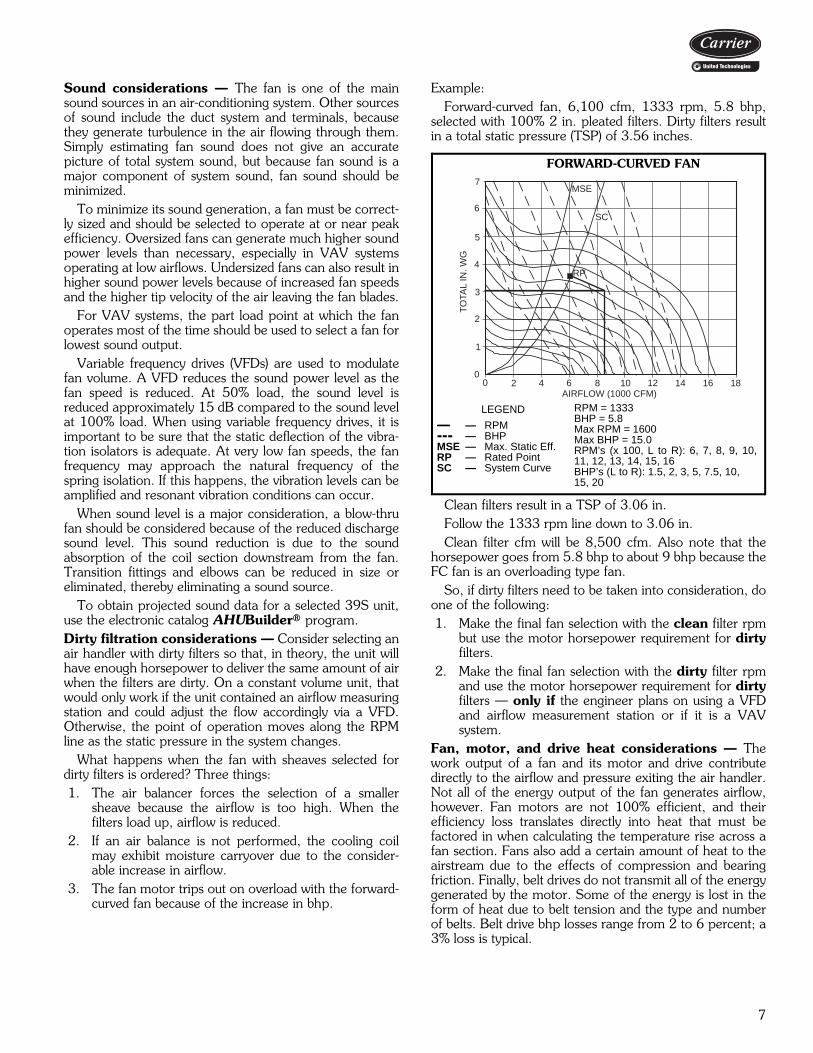
Example:Forward-curved fan, 6,100 cfm, 1333 rpm, 5.8 bhp,
selected with 100% 2 in. pleated filters. Dirty filters resultin a total static pressure (TSP) of 3.56 inches.
Clean filters result in a TSP of 3.06 in.Follow the 1333 rpm line down to 3.06 in.Clean filter cfm will be 8,500 cfm. Also note that the
horsepower goes from 5.8 bhp to about 9 bhp because theFC fan is an overloading type fan.
So, if dirty filters need to be taken into consideration, doone of the following:1. Make the final fan selection with the clean filter rpm
but use the motor horsepower requirement for dirtyfilters.
2. Make the final fan selection with the dirty filter rpmand use the motor horsepower requirement for dirtyfilters — only if the engineer plans on using a VFDand airflow measurement station or if it is a VAVsystem.
Fan, motor, and drive heat considerations — Thework output of a fan and its motor and drive contributedirectly to the airflow and pressure exiting the air handler.Not all of the energy output of the fan generates airflow,however. Fan motors are not 100% efficient, and theirefficiency loss translates directly into heat that must befactored in when calculating the temperature rise across afan section. Fans also add a certain amount of heat to theairstream due to the effects of compression and bearingfriction. Finally, belt drives do not transmit all of the energygenerated by the motor. Some of the energy is lost in theform of heat due to belt tension and the type and numberof belts. Belt drive bhp losses range from 2 to 6 percent; a3% loss is typical.
7
6
5
4
3
2
1
00 2 4 6 8 10 12 14 16 18
AIRFLOW (1000 CFM)
RP
SC
MSE
TO
TAL
IN. W
G
FORWARD-CURVED FAN
RPM = 1333BHP = 5.8Max RPM = 1600Max BHP = 15.0RPM’s (x 100, L to R): 6, 7, 8, 9, 10,11, 12, 13, 14, 15, 16BHP’s (L to R): 1.5, 2, 3, 5, 7.5, 10,15, 20
LEGEND
— — RPM--- — BHPMSE — Max. Static Eff.RP — Rated PointSC — System Curve

8
Because the 39S Series air handlers all have their fans,motors, and drives located within the airstream, heat lossesfrom these components affect the power requirements,cooling load, and heating load.
Power losses in the motor and drive should be allowedfor when determining the motor output (bhp), so that themotor can be correctly sized and so that the additional heatoutput can be subtracted from cooling capacity or added toheating capacity. A typical example follows:Given Fan Operating Point:
13,224 cfm9.6 Fan bhp3.0% estimated drive loss
Calculate the required fan motor output (Hp) due to driveloss:Hp = (Fan bhp) x (Drive Loss)Hp = 9.6 x 1.03Hp = 9.89 hp (select 10 Hp motor)Calculate the total fan motor heat output (Q) according tomotor efficiency:Q = (Motor Output) ÷ (Motor Efficiency [Typical])Q = 9.89 ÷ 0.86Q = 11.5 hpConvert horsepower to Btu per hour.11.5 hp x 2545 = 29,268 BtuhCalculate the increase in leaving-air temperature (T) dueto fan and motor heat and drive losses:Q = 1.1 x cfm x T29,268 Btuh = 1.1 x 13,224 x T29,268 Btuh = 14,546.4 x TT = 2.01 F (use to estimate coil requirements)
Fan applicationCertain fans are more efficient in low-static pressure sys-tems, while others operate best in higher pressure systems.Some fan types are designed to handle very large air vol-umes while others are more efficient at lower volumes. Thelow cost 39S unit is designed for use with low-static pres-sure systems and is only available with forward-curved fans.For higher static applications, specify 39M or 39CC units.Forward-curved (FC) fans are typically used for low tomedium pressure applications (0 to 5 in. wg total staticpressure [TSP]).
The FC fans are reasonably stable over a wide airflow(cfm) range at constant speed. Because of the relatively flatcurve, FC fans tolerate modulation in airflow without largeincreases in static pressure. Most important, FC fans arelowest in first cost.
Duct design considerationsThe discharge ductwork immediately downstream from thefan is critical for successful applications. Poorly designedductwork can degrade fan performance and contributes toexcessive pressure drop and noise.
The 39S Series forward-curved fans are tested as part ofa system with straight discharge ductwork, and the fanratings are based on this duct design. When designingductwork in the field, it is important to use a straight discharge
duct of the correct dimensions to obtain maximum fan perfor-mance. The straight section of ductwork helps the airflow todevelop a uniform velocity profile as it exits the fan and allowsthe velocity pressure to recover into static pressure. See thefigure below.
For 100% recovery of velocity pressure into static pres-sure, the straight portion of the discharge duct must be atleast 21/2 times the discharge diameter in length for veloc-ities of 2500 fpm or less. For each additional 1000 fpm,add one duct diameter to the length of the straight portionof the ductwork.
As an example of how to size the straight portion ofduct, assume the fan has a 34 x 34 in. discharge outlet(8.03 sq ft). The equivalent diameter is 39 in., so thestraight duct length required would be 8 ft long.
Fan control on variable air volume systemsIntroductionWith their inherent characteristics of reducing airflow tomeet demand, VAV systems can be a source of major ener-gy savings, because fan brake horsepower (bhp) varies withthe amount of air delivered.
The degree to which bhp savings are realized, however,is also affected by the type of fan volume control selectedand the effectiveness of its application. Effective fan con-trol assures proper duct pressure for the required controlstability of the air terminals and provides quiet terminalunit operation when “riding the fan curve.”
Consider the following when selecting a fan volume con-trol method:1. System parameters
a. Airflow (cfm)b. Static pressurec. Percent volume reduction (turndown)
2. Fan type and selection pointa. Design point efficiencyb. Part load efficiency (especially the point where the
fan will be operating most of the time)c. Part load stability
3. Ease of control installation and use4. Motor selection
a. Higher bhp inputs due to efficiency of VAV con-trol method
b. Compatibility with VAV control
CUTOFFCENTRIFUGALFAN
100% EFFECTIVE DUCT LENGTH
2 1/2 DIAMETERS AT 2500 FPM
DISCHARGE DUCT
Application data (cont)
9
5. Sound levelsa. Fan-generated soundb. Terminal soundc. Control-generated soundd. System sound (ducts, fittings)
6. Initial cost and operating cost7. Reliability and ease of maintenance
System parametersBefore a fan type or control is selected, the system must beanalyzed at both the design point and part load. The fan islikely to be operating at part load a large percentage of thetime.
Methods of fan air-volume control• “Riding the fan curve” with terminal throttling (forward
curved fans)• Variable frequency drives (VFDs)A short description of these control methods follows. Asummary comparison table is provided at the end of thesection.Forward-curved (FC) fans with terminal throttling(riding fan curve) — This is the simplest, most reliable,and most economical first-cost method of air volume con-trol on VAV systems, since no accessories are required.This type of VAV control can be used on forward-curved
fans with flat pressure characteristics and in systems wherestatic pressure changes at the terminals are moderate. Airvolume reduction is produced solely by throttling of termi-nal units in response to load reduction. As the units throt-tle, system resistance changes.
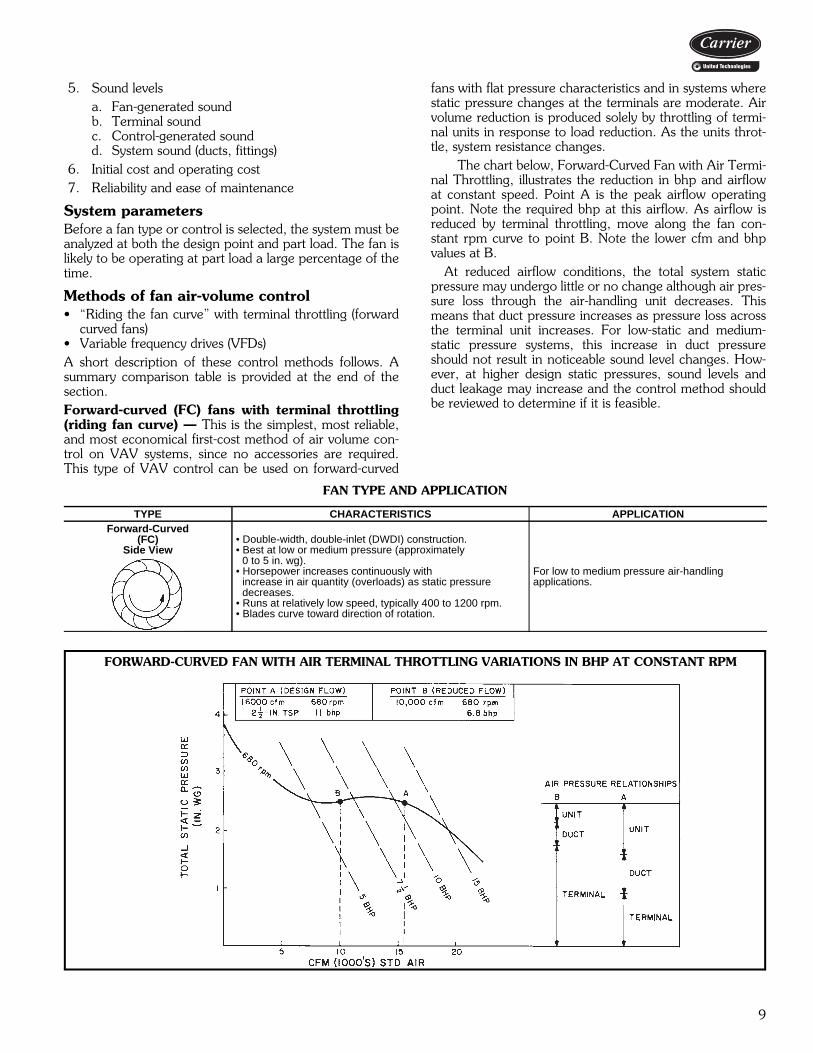
The chart below, Forward-Curved Fan with Air Termi-nal Throttling, illustrates the reduction in bhp and airflowat constant speed. Point A is the peak airflow operatingpoint. Note the required bhp at this airflow. As airflow isreduced by terminal throttling, move along the fan con-stant rpm curve to point B. Note the lower cfm and bhpvalues at B.
At reduced airflow conditions, the total system staticpressure may undergo little or no change although air pres-sure loss through the air-handling unit decreases. Thismeans that duct pressure increases as pressure loss acrossthe terminal unit increases. For low-static and medium-static pressure systems, this increase in duct pressureshould not result in noticeable sound level changes. How-ever, at higher design static pressures, sound levels andduct leakage may increase and the control method shouldbe reviewed to determine if it is feasible.
FAN TYPE AND APPLICATION
TYPE CHARACTERISTICS APPLICATIONForward-Curved
(FC)Side View
• Double-width, double-inlet (DWDI) construction.• Best at low or medium pressure (approximately
0 to 5 in. wg).• Horsepower increases continuously with
increase in air quantity (overloads) as static pressure decreases.
• Runs at relatively low speed, typically 400 to 1200 rpm.• Blades curve toward direction of rotation.
For low to medium pressure air-handlingapplications.
FORWARD-CURVED FAN WITH AIR TERMINAL THROTTLING VARIATIONS IN BHP AT CONSTANT RPM
10
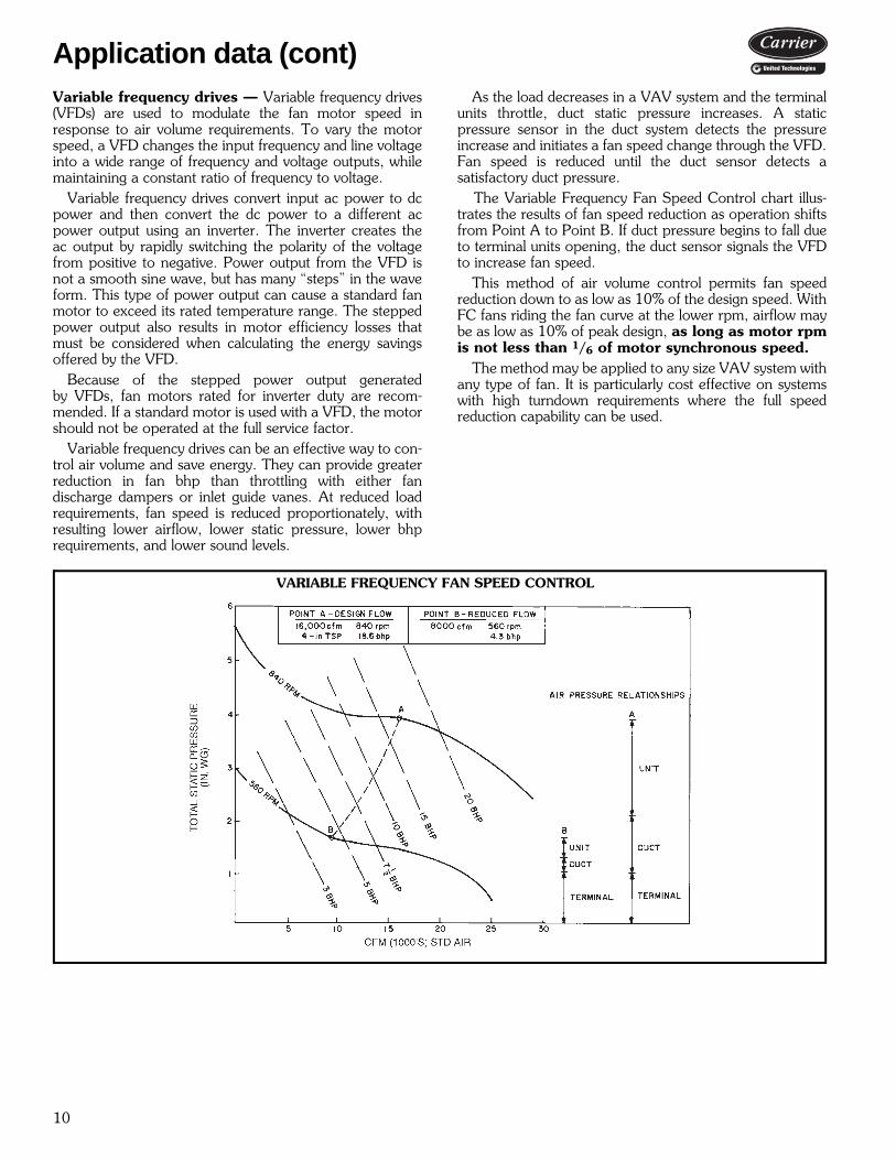
Variable frequency drives — Variable frequency drives(VFDs) are used to modulate the fan motor speed inresponse to air volume requirements. To vary the motorspeed, a VFD changes the input frequency and line voltageinto a wide range of frequency and voltage outputs, whilemaintaining a constant ratio of frequency to voltage.
Variable frequency drives convert input ac power to dcpower and then convert the dc power to a different acpower output using an inverter. The inverter creates theac output by rapidly switching the polarity of the voltagefrom positive to negative. Power output from the VFD isnot a smooth sine wave, but has many “steps” in the waveform. This type of power output can cause a standard fanmotor to exceed its rated temperature range. The steppedpower output also results in motor efficiency losses thatmust be considered when calculating the energy savingsoffered by the VFD.
Because of the stepped power output generatedby VFDs, fan motors rated for inverter duty are recom-mended. If a standard motor is used with a VFD, the motorshould not be operated at the full service factor.
Variable frequency drives can be an effective way to con-trol air volume and save energy. They can provide greaterreduction in fan bhp than throttling with either fandischarge dampers or inlet guide vanes. At reduced loadrequirements, fan speed is reduced proportionately, withresulting lower airflow, lower static pressure, lower bhprequirements, and lower sound levels.
As the load decreases in a VAV system and the terminalunits throttle, duct static pressure increases. A staticpressure sensor in the duct system detects the pressureincrease and initiates a fan speed change through the VFD.Fan speed is reduced until the duct sensor detects asatisfactory duct pressure.
The Variable Frequency Fan Speed Control chart illus-trates the results of fan speed reduction as operation shiftsfrom Point A to Point B. If duct pressure begins to fall dueto terminal units opening, the duct sensor signals the VFDto increase fan speed.
This method of air volume control permits fan speedreduction down to as low as 10% of the design speed. WithFC fans riding the fan curve at the lower rpm, airflow maybe as low as 10% of peak design, as long as motor rpmis not less than 1/6 of motor synchronous speed.
The method may be applied to any size VAV system withany type of fan. It is particularly cost effective on systemswith high turndown requirements where the full speedreduction capability can be used.
VARIABLE FREQUENCY FAN SPEED CONTROL
Application data (cont)

11
FAN SUMMARY COMPARISON
LEGEND *Percentage of modulation of the design airflow.†Including part load.NOTE: Rank is based on a relative scale of 1 to 4. Some methods have compara-ble rating.
Unit control arrangements with Direct Digital ControlsSupply fan controlSupply fan control is used to match the supply fan deliveryto the airflow required by the load in a variable air volumesystem. This is done by maintaining a constant static pres-sure in the supply duct at a point approximately 2/3 of thedistance from the supply fan discharge.
The microprocessor uses a control loop to provide thecapability. This processor measures the static pressure atthe pick-up probe, compares it to the desired set point,and modulates the fan volume control device. See the Sup-ply Fan Control figure. The volume control device can be afactory-installed or field-installed variable frequency drive(VFD).
Inlet guide vanes are not offered on 39S units. For sup-ply fan control, it is recommended that a VFD be used.The VFD offers several advantages over inlet guide vanes.First, the VFD operates more efficiently in most applica-tions, thus saving energy. The VFD also provides the abili-ty to maintain control over a much larger airflow range (ithas a higher turn-down ratio).
The following guideline should be used to ensure propercontrol:
Variable frequency drives should not be operated at be-low 10% of the maximum for which the fan was select-ed, regardless of the fan type.For supply fan applications, the microprocessor option
maintains the duct static pressure at a desired set point be-tween 0.2 and 4.5 in. wg to within ±0.1 in. wg throughoutthe fan control range. In applications where over 100 ft ofpneumatic tubing is required, the transducer must be re-moved from the control box and remotely mounted nearthe static pressure pickup.
Indoor air quality (IAQ) applicationsThe CO2 demand-controlled ventilation override increasesthe minimum ventilation level in order to maintain the CO2level at or below the maximum level per person. Featuresinclude the ability to save energy by ventilating only to theactual rate required, rather than the maximum design occu-pancy rate. When combined with Product IntegratedControls, the feature automatically adapts and changesventilation quantity without operator set point adjustments.The feature has user-selectable values for minimum mixed-air temperature override, maximum damper ventilationoverride position, and supply air tempering (when hotwater/steam heat is used).
TYPE OFCONTROL
FIRST-COST RANK
TURNDOWNRANGE
(Normal)*
SOUNDGENERATION
RANK†
ENERGY-SAVINGS
RANK
APPLICATIONRANGE — NORMAL
FOR AIR COND.COMMENTS
FC FanTerminal Throttling(Riding Fan Curve)
1(Lowest Cost) 60-70% 3 3 TSP 0to 4.5
Cfm 3,000 to 15,000
For moderate turndown systems witha flat fan curve and low to medium staticpressure and cfm range.
FC Fan with2-Speed Motor 3 (Not
Applicable) 2 2 TSP 0to 4.5Cfm 3,000 to 15,000
For systems with predictable 2-loadsituations in low to medium staticpressure range. Controls are morecomplicated. Starters are more costly.
FC Fan With Variable
Frequency Drive2 10-15% 1
(Quietest)1
(Best)TSP 0to 4.5
Cfm 3,000 to 15,000
For high turndown, low to medium static pressure systems. Best energy savings. Fast payback. Fan generates least sound.
FC — Forward CurvedTSP — Total Static Pressure
SUPPLY FAN CONTROL
OUTDOORAIR
MXB
FILTER COIL SUPPLY FAN
2/3 DUCT LENGTH
P
DDCCONTROL BOX
MOTOR
VFD
RETURNAIR
DDC — Direct Digital ControlMXB — Mixing BoxVFD — Variable Frequency
Drive
LEGEND
Static Pressure Pick-Up
12
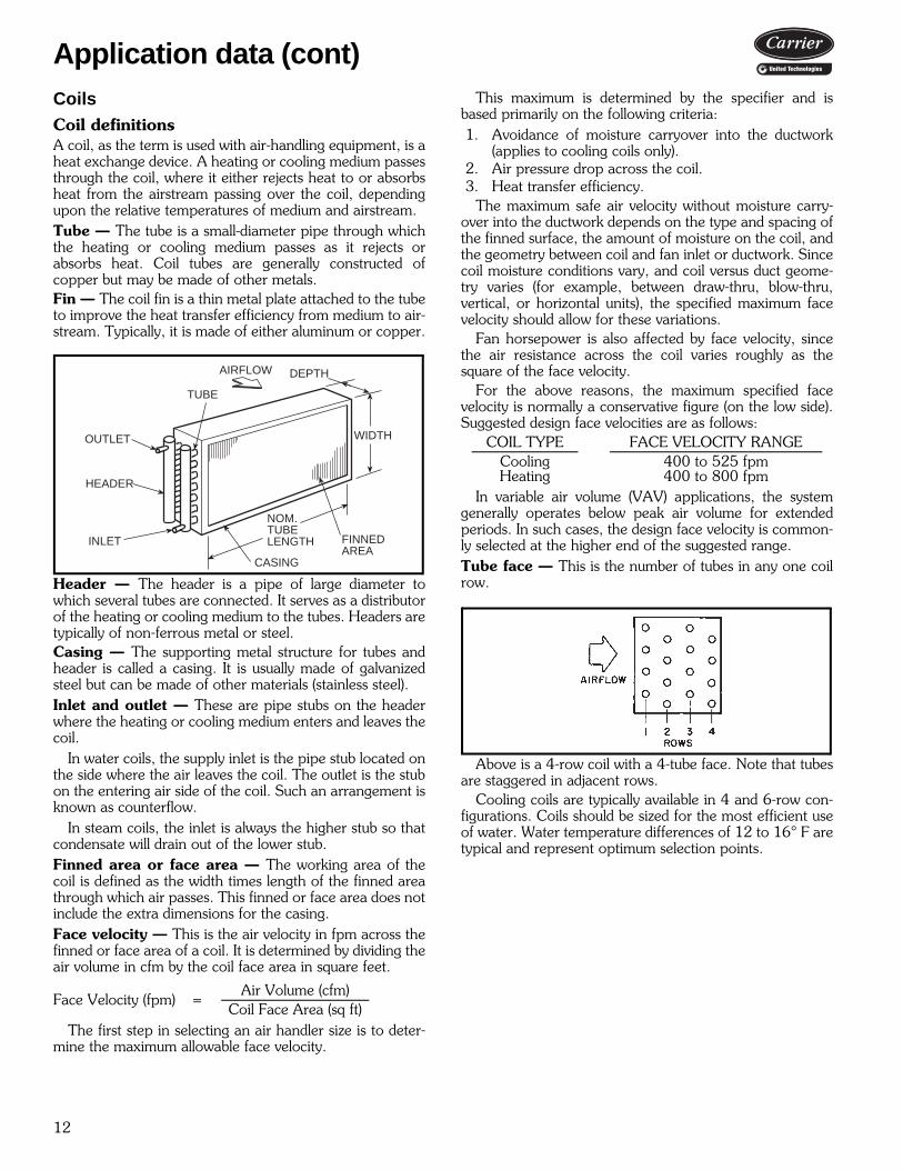
CoilsCoil definitionsA coil, as the term is used with air-handling equipment, is aheat exchange device. A heating or cooling medium passesthrough the coil, where it either rejects heat to or absorbsheat from the airstream passing over the coil, dependingupon the relative temperatures of medium and airstream.Tube — The tube is a small-diameter pipe through whichthe heating or cooling medium passes as it rejects orabsorbs heat. Coil tubes are generally constructed ofcopper but may be made of other metals.Fin — The coil fin is a thin metal plate attached to the tubeto improve the heat transfer efficiency from medium to air-stream. Typically, it is made of either aluminum or copper.
Header — The header is a pipe of large diameter towhich several tubes are connected. It serves as a distributorof the heating or cooling medium to the tubes. Headers aretypically of non-ferrous metal or steel.Casing — The supporting metal structure for tubes andheader is called a casing. It is usually made of galvanizedsteel but can be made of other materials (stainless steel).Inlet and outlet — These are pipe stubs on the headerwhere the heating or cooling medium enters and leaves thecoil.
In water coils, the supply inlet is the pipe stub located onthe side where the air leaves the coil. The outlet is the stubon the entering air side of the coil. Such an arrangement isknown as counterflow.
In steam coils, the inlet is always the higher stub so thatcondensate will drain out of the lower stub.Finned area or face area — The working area of thecoil is defined as the width times length of the finned areathrough which air passes. This finned or face area does notinclude the extra dimensions for the casing.Face velocity — This is the air velocity in fpm across thefinned or face area of a coil. It is determined by dividing theair volume in cfm by the coil face area in square feet.
The first step in selecting an air handler size is to deter-mine the maximum allowable face velocity.
This maximum is determined by the specifier and isbased primarily on the following criteria:1. Avoidance of moisture carryover into the ductwork
(applies to cooling coils only).2. Air pressure drop across the coil.3. Heat transfer efficiency.
The maximum safe air velocity without moisture carry-over into the ductwork depends on the type and spacing ofthe finned surface, the amount of moisture on the coil, andthe geometry between coil and fan inlet or ductwork. Sincecoil moisture conditions vary, and coil versus duct geome-try varies (for example, between draw-thru, blow-thru,vertical, or horizontal units), the specified maximum facevelocity should allow for these variations.
Fan horsepower is also affected by face velocity, sincethe air resistance across the coil varies roughly as thesquare of the face velocity.
For the above reasons, the maximum specified facevelocity is normally a conservative figure (on the low side).Suggested design face velocities are as follows:
In variable air volume (VAV) applications, the systemgenerally operates below peak air volume for extendedperiods. In such cases, the design face velocity is common-ly selected at the higher end of the suggested range.Tube face — This is the number of tubes in any one coilrow.
Above is a 4-row coil with a 4-tube face. Note that tubesare staggered in adjacent rows.
Cooling coils are typically available in 4 and 6-row con-figurations. Coils should be sized for the most efficient useof water. Water temperature differences of 12 to 16° F aretypical and represent optimum selection points.
Face Velocity (fpm) =Air Volume (cfm)
Coil Face Area (sq ft)
OUTLET
HEADER
TUBE
INLET
WIDTH
NOM.TUBELENGTH
CASING
FINNEDAREA
DEPTHAIRFLOW
COIL TYPE FACE VELOCITY RANGECooling 400 to 525 fpmHeating 400 to 800 fpm
Application data (cont)
13
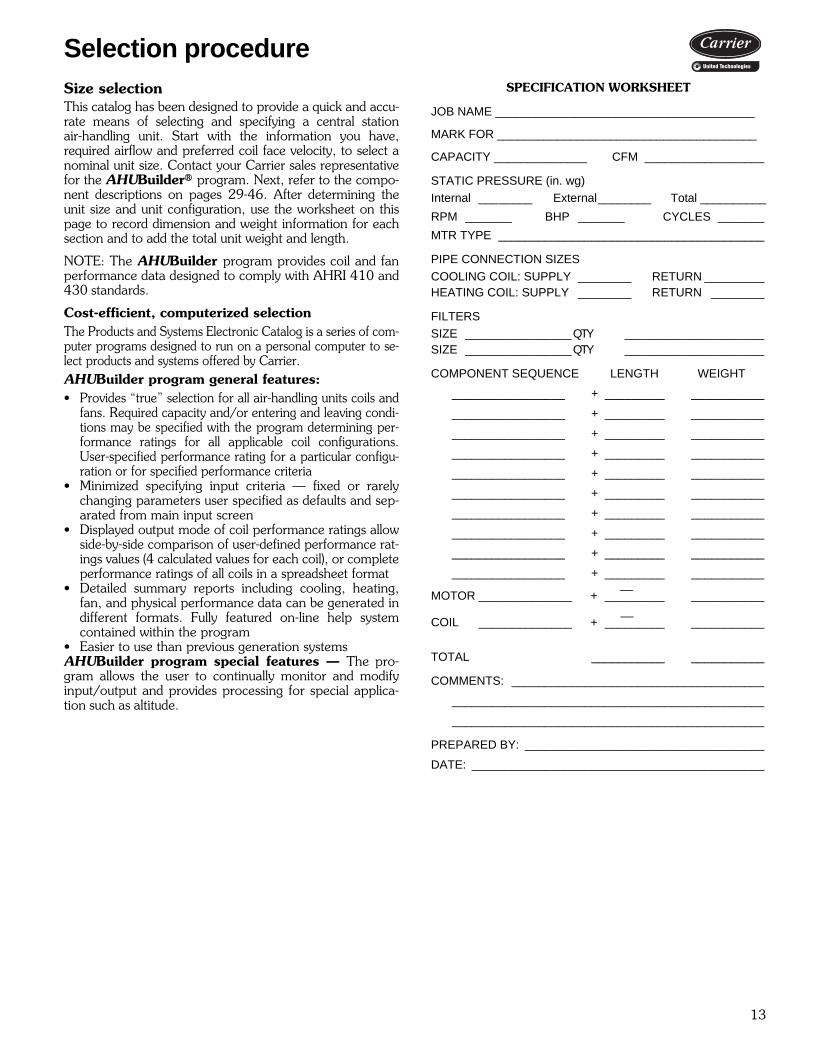
Size selectionThis catalog has been designed to provide a quick and accu-rate means of selecting and specifying a central stationair-handling unit. Start with the information you have,required airflow and preferred coil face velocity, to select anominal unit size. Contact your Carrier sales representativefor the AHUBuilder® program. Next, refer to the compo-nent descriptions on pages 29-46. After determining theunit size and unit configuration, use the worksheet on thispage to record dimension and weight information for eachsection and to add the total unit weight and length.
NOTE: The AHUBuilder program provides coil and fanperformance data designed to comply with AHRI 410 and430 standards.
Cost-efficient, computerized selectionThe Products and Systems Electronic Catalog is a series of com-puter programs designed to run on a personal computer to se-lect products and systems offered by Carrier.AHUBuilder program general features:• Provides “true” selection for all air-handling units coils and
fans. Required capacity and/or entering and leaving condi-tions may be specified with the program determining per-formance ratings for all applicable coil configurations.User-specified performance rating for a particular configu-ration or for specified performance criteria
• Minimized specifying input criteria — fixed or rarelychanging parameters user specified as defaults and sep-arated from main input screen
• Displayed output mode of coil performance ratings allowside-by-side comparison of user-defined performance rat-ings values (4 calculated values for each coil), or completeperformance ratings of all coils in a spreadsheet format
• Detailed summary reports including cooling, heating,fan, and physical performance data can be generated indifferent formats. Fully featured on-line help systemcontained within the program
• Easier to use than previous generation systemsAHUBuilder program special features — The pro-gram allows the user to continually monitor and modifyinput/output and provides processing for special applica-tion such as altitude.
SPECIFICATION WORKSHEET
JOB NAME _______________________________________
MARK FOR _______________________________________
CAPACITY ______________ CFM __________________
STATIC PRESSURE (in. wg)Internal ________ External________ Total __________
RPM _______ BHP _______ CYCLES _______
MTR TYPE ________________________________________
PIPE CONNECTION SIZES
COOLING COIL: SUPPLY ________ RETURN _________HEATING COIL: SUPPLY ________ RETURN ________
FILTERSSIZE ________________QTY _____________________SIZE ________________QTY _____________________
COMPONENT SEQUENCE LENGTH WEIGHT
_________________ + _________ ___________
_________________ + _________ ___________
_________________ + _________ ___________
_________________ + _________ ___________
_________________ + _________ ___________
_________________ + _________ ___________
_________________ + _________ ___________
_________________ + _________ ___________
_________________ + _________ ___________
_________________ + _________ ___________
MOTOR ______________ + _________ ___________
COIL ______________ + _________ ___________
TOTAL ___________ ___________
COMMENTS: ______________________________________
_______________________________________________
_______________________________________________
PREPARED BY: ____________________________________
DATE: ____________________________________________
Selection procedure
—
—

14
Electric heat selection procedureI Determine electric heat requirements based
on size of selected unit.Given:Air Quantity . . . . . . . . . . . . . . . . . . . . 3,000 cfmEntering-Air Temperature . . . . . . . . . . . . . . .54 FLeaving-Air Temperature . . . . . . . . . . . . . . . .77 FMaximum Air Velocity . . . . . . . . . . . . . . .650 fpmElectric Service . . . . . . . . . . . . 460-v, 3-ph, 60-HzUnit Type. . . . . . . . . . . . . . Horizontal Draw-Thru
II Determine heating load.Heating Load = 1.1 x Cfm x Air Temp Rise
= 1.1 x 3,000 x 23= 75,900 Btuh (75.9 MBtuh)
III Verify unit size.Size of the electric heating coil face area is usuallypredetermined by the selection of the air-handlingunit and the cooling coil. However, the heater sizemust be checked to assure that the minimum facevelocity is provided for the heater.
IV Determine kilowatt equivalent of heatingload.
V Determine unit electric heater size.Select the heater which has a kW rating closest tobut greater than the required kW and is available atthe required voltage.
VI Determine capacity of electric heater.
VII Calculate air temperature rise.
VIII Calculate the actual leaving-air temperature.
IX Voltage variations.Variations from the rated voltage of the electricheating coils can significantly affect the coil’s ratedoutput. The effects of voltage variation can be deter-mined by the following formula.
Air-handling selection guide1. Unit size = Coil face area (ft2) = design cfm/max face
velocityExample: 4,000 cfm/500 fpm = 8 Size 09
2. Consider your system and choose the appropriate com-ponent sections.
3. Determine overall unit dimensions and weight. Theheight and width for any given unit size is the same forall component sections.
4. Finalize your selections using the latest version of theAHUBuilder® program. The AHUBuilder programis a comprehensive selection tool designed to help cus-tomers make the proper air handler choice quickly andefficiently.
Minimum Face Area =3,000
650 fpm
= 4.6 sq ft
Actual Face Velocity =3,000 (Actual Coil
Face Area)4.9 sq ft= 615 fpm
kW Heating Load =75.9 MBtuh
3.413 MBtuh/kW
=75.9
3.413
= 22.2 kW
Capacity = 23 kW x 3.413= 78.5 MBtuh
Air Temp Rise =78,500 Btuh
1.1 x 3,000 Cfm
= 23.8 F
Leaving Air Temp= Ent Air Temp + Air Temp Rise= 54 + 23.8= 77.8 F
kWa = kWr x ( Va )2
Vr
kWa = Actual kW Output From CoilkWr = Rated kW Output From CoilVa = Actual Voltage at CoilVr = Rated Voltage at Coil
Selection procedure (cont)

15
Refer to the AHUBuilder program for 39S unit perfor-mance data.
ELECTRIC HEATER DATA
39SH SINGLE PHASE
LEGEND
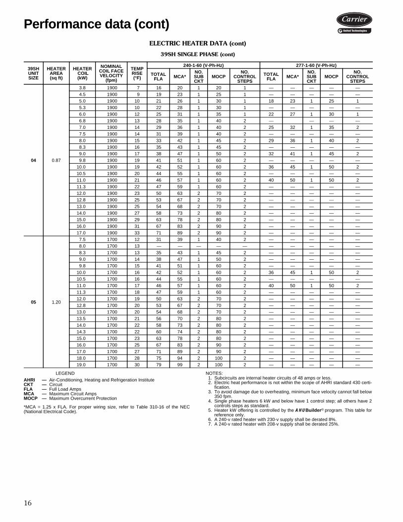
*MCA = 1.25 x FLA. For proper wiring size, refer to Table 310-16 of the NEC(National Electrical Code).
NOTES:1. Subcircuits are internal heater circuits of 48 amps or less.2. Electric heat performance is not within the scope of AHRI standard 430 certi-
fication.3. To avoid damage due to overheating, minimum face velocity cannot fall below
350 fpm.4. Single phase heaters 6 kW and below have 1 control step; all others have 2
controls steps as standard.5. Heater kW offering is controlled by the AHUBuilder® program. This table for
reference only.6. A 240-v rated heater with 230-v supply shall be derated 8%.7. A 240-v rated heater with 208-v supply shall be derated 25%.
39SHUNIT SIZE
HEATER AREA (sq ft)
HEATER COIL(kW)
NOMINALCOIL FACEVELOCITY
(fpm)
TEMPRISE(°F)
240-1-60 (V-Ph-Hz) 277-1-60 (V-Ph-Hz)
TOTALFLA MCA*
NO.SUBCKT
MOCPNO.
CONTROLSTEPS
TOTALFLA MCA*
NO.SUBCKT
MOCPNO.
CONTROLSTEPS
00 0.63
0.8 700 6 3 4 1 15 1 — — — — —1.0 700 7 4 5 1 15 1 4 5 1 15 11.5 700 11 6 8 1 15 1 — — — — —2.0 700 15 8 10 1 15 1 7 9 1 15 12.3 700 17 10 12 1 15 1 — — — — —3.0 700 22 13 16 1 20 1 11 14 1 15 14.0 700 29 17 21 1 25 1 14 18 1 20 1
01 0.63
0.8 1000 4 3 4 1 15 1 — — — — —1.0 1000 5 4 5 1 15 1 4 5 1 15 11.5 1000 8 6 8 1 15 1 — — — — —2.0 1000 10 8 10 1 15 1 7 9 1 15 12.3 1000 12 10 12 1 15 1 — — — — —3.0 1000 15 13 16 1 20 1 11 14 1 15 13.8 1000 19 16 20 1 20 1 — — — — —4.0 1000 20 17 21 1 25 1 14 18 1 20 14.5 1000 23 19 23 1 25 1 — — — — —5.0 1000 25 21 26 1 30 1 18 23 1 25 16.0 1000 31 25 31 1 35 1 22 27 1 30 1
02 0.61
3.8 1400 14 16 20 1 20 1 — — — — —4.5 1400 17 19 23 1 25 1 — — — — —5.0 1400 19 21 26 1 30 1 18 23 1 25 15.3 1400 20 22 28 1 30 1 — — — — —6.0 1400 22 25 31 1 35 1 22 27 1 30 16.8 1400 25 28 35 1 40 2 — — — — —7.0 1400 26 29 36 1 40 2 25 32 1 35 27.5 1400 28 31 39 1 40 2 — — — — —8.0 1400 30 33 42 1 45 2 29 36 1 40 29.0 1400 33 38 47 1 50 2 32 41 1 45 2
10.0 1400 37 42 52 1 60 2 36 45 1 50 2
03 0.61
3.8 2000 10 16 20 1 20 1 — — — — —4.5 2000 12 19 23 1 25 1 — — — — —5.0 2000 13 21 26 1 30 1 18 23 1 25 15.3 2000 14 22 28 1 30 1 — — — — —6.0 2000 16 25 31 1 35 1 22 27 1 30 16.8 2000 18 28 35 1 40 2 — — — — —7.0 2000 18 29 36 1 40 2 25 32 1 35 27.5 2000 19 31 39 1 40 2 — — — — —8.0 2000 21 33 42 1 45 2 29 36 1 40 29.0 2000 23 38 47 1 50 2 32 41 1 45 2
10.0 2000 26 42 52 1 60 2 36 45 1 50 2
AHRI — Air-Conditioning, Heating and Refrigeration InstituteCKT — CircuitFLA — Full Load AmpsMCA — Maximum Circuit AmpsMOCP — Maximum Overcurrent Protection
Performance data
16
ELECTRIC HEATER DATA (cont)
39SH SINGLE PHASE (cont)
LEGEND
*MCA = 1.25 x FLA. For proper wiring size, refer to Table 310-16 of the NEC(National Electrical Code).
NOTES:1. Subcircuits are internal heater circuits of 48 amps or less.2. Electric heat performance is not within the scope of AHRI standard 430 certi-
fication.3. To avoid damage due to overheating, minimum face velocity cannot fall below
350 fpm.4. Single phase heaters 6 kW and below have 1 control step; all others have 2
controls steps as standard.5. Heater kW offering is controlled by the AHUBuilder® program. This table for
reference only.6. A 240-v rated heater with 230-v supply shall be derated 8%.7. A 240-v rated heater with 208-v supply shall be derated 25%.
39SHUNIT SIZE
HEATER AREA (sq ft)
HEATER COIL(kW)
NOMINALCOIL FACEVELOCITY
(fpm)
TEMPRISE(°F)
240-1-60 (V-Ph-Hz) 277-1-60 (V-Ph-Hz)
TOTALFLA MCA*
NO.SUBCKT
MOCPNO.
CONTROLSTEPS
TOTALFLA MCA*
NO.SUBCKT
MOCPNO.
CONTROLSTEPS
04 0.87
3.8 1900 7 16 20 1 20 1 — — — — —4.5 1900 9 19 23 1 25 1 — — — — —5.0 1900 10 21 26 1 30 1 18 23 1 25 15.3 1900 10 22 28 1 30 1 — — — — —6.0 1900 12 25 31 1 35 1 22 27 1 30 16.8 1900 13 28 35 1 40 2 — — — —7.0 1900 14 29 36 1 40 2 25 32 1 35 27.5 1900 14 31 39 1 40 2 — — — — —8.0 1900 15 33 42 1 45 2 29 36 1 40 28.3 1900 16 35 43 1 45 2 — — — — —9.0 1900 17 38 47 1 50 2 32 41 1 45 29.8 1900 19 41 51 1 60 2 — — — — —
10.0 1900 19 42 52 1 60 2 36 45 1 50 210.5 1900 20 44 55 1 60 2 — — — — —11.0 1900 21 46 57 1 60 2 40 50 1 50 211.3 1900 22 47 59 1 60 2 — — — — —12.0 1900 23 50 63 2 70 2 — — — — —12.8 1900 25 53 67 2 70 2 — — — — —13.0 1900 25 54 68 2 70 2 — — — — —14.0 1900 27 58 73 2 80 2 — — — — —15.0 1900 29 63 78 2 80 2 — — — — —16.0 1900 31 67 83 2 90 2 — — — — —17.0 1900 33 71 89 2 90 2 — — — — —
05 1.20
7.5 1700 12 31 39 1 40 2 — — — — —8.0 1700 13 — — — — — — — — — —8.3 1700 13 35 43 1 45 2 — — — — —9.0 1700 14 38 47 1 50 2 — — — — —9.8 1700 15 41 51 1 60 2 — — — — —
10.0 1700 16 42 52 1 60 2 36 45 1 50 210.5 1700 16 44 55 1 60 2 — — — — —11.0 1700 17 46 57 1 60 2 40 50 1 50 211.3 1700 18 47 59 1 60 2 — — — — —12.0 1700 19 50 63 2 70 2 — — — — —12.8 1700 20 53 67 2 70 2 — — — — —13.0 1700 20 54 68 2 70 2 — — — — —13.5 1700 21 56 70 2 80 2 — — — — —14.0 1700 22 58 73 2 80 2 — — — — —14.3 1700 22 60 74 2 80 2 — — — — —15.0 1700 23 63 78 2 80 2 — — — — —16.0 1700 25 67 83 2 90 2 — — — — —17.0 1700 27 71 89 2 90 2 — — — — —18.0 1700 28 75 94 2 100 2 — — — — —19.0 1700 30 79 99 2 100 2 — — — — —
AHRI — Air-Conditioning, Heating and Refrigeration InstituteCKT — CircuitFLA — Full Load AmpsMCA — Maximum Circuit AmpsMOCP — Maximum Overcurrent Protection
Performance data (cont)

17
ELECTRIC HEATER DATA (cont)
39SH SINGLE PHASE (cont)
LEGEND
*MCA = 1.25 x FLA. For proper wiring size, refer to Table 310-16 of the NEC(National Electrical Code).
NOTES:1. Subcircuits are internal heater circuits of 48 amps or less.2. Electric heat performance is not within the scope of AHRI standard 430 certi-
fication.3. To avoid damage due to overheating, minimum face velocity cannot fall below
350 fpm.4. Single phase heaters 6 kW and below have 1 control step; all others have 2
controls steps as standard.5. Heater kW offering is controlled by the AHUBuilder® program. This table for
reference only.6. A 240-v rated heater with 230-v supply shall be derated 8%.7. A 240-v rated heater with 208-v supply shall be derated 25%.
39SHUNIT SIZE
HEATER AREA (sq ft)
HEATER COIL(kW)
NOMINALCOIL FACEVELOCITY
(fpm)
TEMPRISE(°F)
240-1-60 (V-Ph-Hz) 277-1-60 (V-Ph-Hz)
TOTALFLA MCA*
NO.SUBCKT
MOCPNO.
CONTROLSTEPS
TOTALFLA MCA*
NO.SUBCKT
MOCPNO.
CONTROLSTEPS
07 1.50
9.0 2000 10 38 47 1 50 2 — — — — —9.8 2000 10 41 51 1 60 2 — — — — —
10.0 2000 11 — — — — — — — — — —10.5 2000 11 44 55 1 60 2 — — — — —11.0 2000 12 — — — — — — — — — —11.3 2000 12 47 59 1 60 2 — — — — —12.0 2000 13 50 63 2 70 2 — — — — —12.8 2000 14 53 67 2 70 2 — — — — —13.0 2000 14 54 68 2 70 2 — — — — —13.5 2000 14 56 70 2 80 2 — — — — —14.0 2000 15 58 73 2 80 2 — — — — —14.3 2000 15 60 74 2 80 2 — — — — —15.0 2000 16 63 78 2 80 2 — — — — —15.8 2000 17 66 82 2 90 2 — — — — —16.0 2000 17 67 83 2 90 2 — — — — —17.0 2000 18 71 89 2 90 2 — — — — —18.0 2000 19 75 94 2 100 2 — — — — —19.0 2000 20 79 99 2 100 2 — — — — —20.0 2000 21 83 104 2 110 2 — — — — —21.0 2000 22 88 109 2 110 2 — — — — —
09 1.50
10.0 2700 8 — — — — — — — — — —11.0 2700 9 — — — — — — — — — —12.0 2700 9 — — — — — — — — — —12.8 2700 10 53 67 2 70 2 — — — — —13.0 2700 10 — — — — — — — — — —13.5 2700 11 56 70 2 80 2 — — — — —14.0 2700 11 — — — — — — — — — —14.3 2700 11 60 74 2 80 2 — — — — —15.0 2700 12 63 78 2 80 2 — — — — —15.8 2700 12 66 82 2 80 2 — — — — —16.0 2700 13 — — — — — — — — — —17.0 2700 13 71 89 2 90 2 — — — — —18.0 2700 14 75 94 2 100 2 — — — — —19.0 2700 15 79 99 2 100 2 — — — — —20.0 2700 16 83 104 2 110 2 — — — — —21.0 2700 17 88 109 2 110 2 — — — — —
AHRI — Air-Conditioning, Heating and Refrigeration InstituteCKT — CircuitFLA — Full Load AmpsMCA — Maximum Circuit AmpsMOCP — Maximum Overcurrent Protection

18
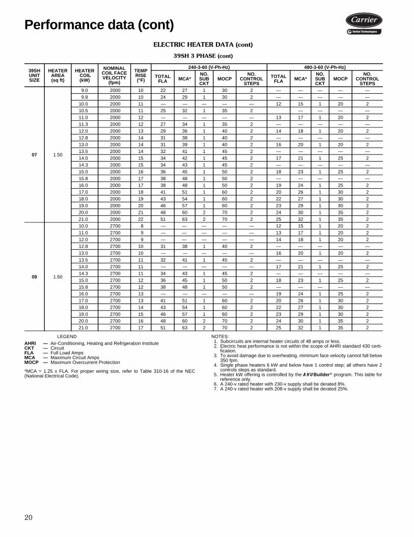
ELECTRIC HEATER DATA (cont)
39SH 3 PHASE
LEGEND
*MCA = 1.25 x FLA. For proper wiring size, refer to Table 310-16 of the NEC(National Electrical Code).
NOTES:1. Subcircuits are internal heater circuits of 48 amps or less.2. Electric heat performance is not within the scope of AHRI standard 430 certi-
fication.3. To avoid damage due to overheating, minimum face velocity cannot fall below
350 fpm.4. Single phase heaters 6 kW and below have 1 control step; all others have 2
controls steps as standard.5. Heater kW offering is controlled by the AHUBuilder® program. This table for
reference only.6. A 240-v rated heater with 230-v supply shall be derated 8%.7. A 240-v rated heater with 208-v supply shall be derated 25%.
39SHUNIT SIZE
HEATER AREA (sq ft)
HEATER COIL(kW)
NOMINALCOIL FACEVELOCITY
(fpm)
TEMPRISE(°F)
240-3-60 (V-Ph-Hz) 480-3-60 (V-Ph-Hz)
TOTALFLA MCA*
NO.SUBCKT
MOCPNO.
CONTROLSTEPS
TOTALFLA MCA*
NO.SUBCKT
MOCPNO.
CONTROLSTEPS
00 0.63
0.8 700 6 2 2 1 15 2 — — — — —1.0 700 7 2 3 1 15 2 — — -— -— -—1.5 700 11 4 5 1 15 2 — — -— -— -—2.0 700 15 5 6 1 15 2 2 3 1 15 22.3 700 17 6 7 1 15 2 -— -— -— — —3.0 700 22 7 9 1 15 2 4 5 1 15 24.0 700 29 10 12 1 15 2 5 6 1 15 2
01 0.63
0.8 1000 4 2 2 1 15 2 — — — — —1.0 1000 5 2 3 1 15 2 — — — — —1.5 1000 8 4 5 1 15 2 — — — — —2.0 1000 10 5 6 1 15 2 2 3 1 15 22.3 1000 12 6 7 1 15 2 — — — — —3.0 1000 15 7 9 1 15 2 4 5 1 15 23.8 1000 19 9 11 1 15 2 — — — — —4.0 1000 20 10 12 1 15 2 5 6 1 15 24.5 1000 23 11 14 1 15 2 — — — — —5.0 1000 25 12 15 1 20 2 6 8 1 15 26.0 1000 31 14 18 1 20 2 7 9 1 15 2
02 0.61
3.8 1400 14 9 11 1 15 2 — — — — —4.5 1400 17 11 14 1 15 2 — — — — —5.0 1400 19 12 15 1 20 2 6 8 1 15 25.3 1400 20 13 16 1 20 2 — — — — —6.0 1400 22 14 18 1 20 2 7 9 1 15 26.8 1400 25 16 20 1 25 2 — — — — —7.0 1400 26 17 21 1 25 2 8 11 1 15 27.5 1400 28 18 23 1 25 2 — — — — —8.0 1400 30 19 24 1 25 2 10 12 1 15 29.0 1400 33 22 27 1 30 2 11 14 1 15 2
10.0 1400 37 24 30 1 35 2 12 15 1 20 2
03 0.61
3.8 2000 10 9 11 1 15 2 — — — — —4.5 2000 12 11 14 1 15 2 — — — — —5.0 2000 13 12 15 1 20 2 6 8 1 15 25.3 2000 14 13 16 1 20 2 — — — — —6.0 2000 16 14 18 1 20 2 7 9 1 15 26.8 2000 18 16 20 1 25 2 — — — — —7.0 2000 18 17 21 1 25 2 8 11 1 15 27.5 2000 19 18 23 1 25 2 — — — — —8.0 2000 21 19 24 1 25 2 10 12 1 15 29.0 2000 23 22 27 1 30 2 11 14 1 15 2
10.0 2000 26 24 30 1 35 2 12 15 1 20 2
AHRI — Air-Conditioning, Heating and Refrigeration InstituteCKT — CircuitFLA — Full Load AmpsMCA — Maximum Circuit AmpsMOCP — Maximum Overcurrent Protection
Performance data (cont)

19
ELECTRIC HEATER DATA (cont)
39SH 3 PHASE (cont)
LEGEND
*MCA = 1.25 x FLA. For proper wiring size, refer to Table 310-16 of the NEC(National Electrical Code).
NOTES:1. Subcircuits are internal heater circuits of 48 amps or less.2. Electric heat performance is not within the scope of AHRI standard 430 certi-
fication.3. To avoid damage due to overheating, minimum face velocity cannot fall below
350 fpm.4. Single phase heaters 6 kW and below have 1 control step; all others have 2
controls steps as standard.5. Heater kW offering is controlled by the AHUBuilder® program. This table for
reference only.6. A 240-v rated heater with 230-v supply shall be derated 8%.7. A 240-v rated heater with 208-v supply shall be derated 25%.
39SHUNIT SIZE
HEATER AREA (sq ft)
HEATER COIL(kW)
NOMINALCOIL FACEVELOCITY
(fpm)
TEMPRISE(°F)
240-3-60 (V-Ph-Hz) 480-3-60 (V-Ph-Hz)
TOTALFLA MCA*
NO.SUBCKT
MOCPNO.
CONTROLSTEPS
TOTALFLA MCA*
NO.SUBCKT
MOCPNO.
CONTROLSTEPS
04 0.87
3.8 1900 7 9 11 1 15 2 — — — — —4.5 1900 9 11 14 1 15 2 — — — — —5.0 1900 10 12 15 1 20 2 6 8 1 15 25.3 1900 10 13 16 1 20 2 — — — — —6.0 1900 12 14 18 1 20 2 7 9 1 15 26.8 1900 13 16 20 1 25 2 — — — — —7.0 1900 14 17 21 1 25 2 8 11 1 15 27.5 1900 14 18 23 1 25 2 — — — — —8.0 1900 15 19 24 1 25 2 10 12 1 15 28.3 1900 16 20 25 1 25 2 — — — — —9.0 1900 17 22 27 1 30 2 11 14 1 15 29.8 1900 19 24 29 1 30 2 — — — — —
10.0 1900 19 24 30 1 35 2 12 15 1 20 210.5 1900 20 25 32 1 35 2 — — — — —11.0 1900 21 26 33 1 35 2 13 17 1 20 211.3 1900 22 27 34 1 35 2 — — — — —12.0 1900 23 29 36 1 40 2 14 18 1 20 212.8 1900 25 31 38 1 40 2 — — — — —13.0 1900 25 31 39 1 40 2 16 20 1 20 214.0 1900 27 34 42 1 45 2 17 21 1 25 215.0 1900 29 36 45 1 50 2 18 23 1 25 216.0 1900 31 38 48 1 50 2 19 24 1 25 217.0 1900 33 41 51 1 60 2 20 26 1 30 2
05 1.20
7.5 1700 12 18 23 1 25 2 — — — — —8.0 1700 13 — — — — — — — — — —8.3 1700 13 20 25 1 25 2 — — — — —9.0 1700 14 22 27 1 30 2 — — — — —9.8 1700 15 24 29 1 30 2 — — — — —
10.0 1700 16 24 30 1 35 2 12 15 1 20 210.5 1700 16 25 32 1 35 2 — — — — —11.0 1700 17 26 33 1 35 2 13 17 1 20 211.3 1700 18 27 34 1 35 2 — — — — —12.0 1700 19 29 36 1 40 2 14 18 1 20 212.8 1700 20 31 38 1 40 2 — — — — —13.0 1700 20 31 39 1 40 2 16 20 1 20 213.5 1700 21 32 41 1 45 2 — — — — —14.0 1700 22 34 42 1 45 2 17 21 1 25 214.3 1700 22 34 43 1 45 2 — — — — —15.0 1700 23 36 45 1 50 2 18 23 1 25 216.0 1700 25 38 48 1 50 2 19 24 1 25 217.0 1700 27 41 51 1 60 2 20 26 1 30 218.0 1700 28 43 54 1 60 2 22 27 1 30 219.0 1700 30 46 57 1 60 2 23 29 1 30 2
AHRI — Air-Conditioning, Heating and Refrigeration InstituteCKT — CircuitFLA — Full Load AmpsMCA — Maximum Circuit AmpsMOCP — Maximum Overcurrent Protection
20
ELECTRIC HEATER DATA (cont)
39SH 3 PHASE (cont)
LEGEND
*MCA = 1.25 x FLA. For proper wiring size, refer to Table 310-16 of the NEC(National Electrical Code).
NOTES:1. Subcircuits are internal heater circuits of 48 amps or less.2. Electric heat performance is not within the scope of AHRI standard 430 certi-
fication.3. To avoid damage due to overheating, minimum face velocity cannot fall below
350 fpm.4. Single phase heaters 6 kW and below have 1 control step; all others have 2
controls steps as standard.5. Heater kW offering is controlled by the AHUBuilder® program. This table for
reference only.6. A 240-v rated heater with 230-v supply shall be derated 8%.7. A 240-v rated heater with 208-v supply shall be derated 25%.
39SHUNIT SIZE
HEATER AREA (sq ft)
HEATER COIL(kW)
NOMINALCOIL FACEVELOCITY
(fpm)
TEMPRISE(°F)
240-3-60 (V-Ph-Hz) 480-3-60 (V-Ph-Hz)
TOTALFLA MCA*
NO.SUBCKT
MOCPNO.
CONTROLSTEPS
TOTALFLA MCA*
NO.SUBCKT
MOCPNO.
CONTROLSTEPS
07 1.50
9.0 2000 10 22 27 1 30 2 — — — — —9.8 2000 10 24 29 1 30 2 — — — — —
10.0 2000 11 — — — — — 12 15 1 20 210.5 2000 11 25 32 1 35 2 — — — —11.0 2000 12 — — — — — 13 17 1 20 211.3 2000 12 27 34 1 35 2 — — — — —12.0 2000 13 29 36 1 40 2 14 18 1 20 212.8 2000 14 31 38 1 40 2 — — — — —13.0 2000 14 31 39 1 40 2 16 20 1 20 213.5 2000 14 32 41 1 45 2 — — — — —14.0 2000 15 34 42 1 45 2 17 21 1 25 214.3 2000 15 34 43 1 45 2 — — — — —15.0 2000 16 36 45 1 50 2 18 23 1 25 215.8 2000 17 38 48 1 50 2 — — — — —16.0 2000 17 38 48 1 50 2 19 24 1 25 217.0 2000 18 41 51 1 60 2 20 26 1 30 218.0 2000 19 43 54 1 60 2 22 27 1 30 219.0 2000 20 46 57 1 60 2 23 29 1 30 220.0 2000 21 48 60 2 70 2 24 30 1 35 221.0 2000 22 51 63 2 70 2 25 32 1 35 2
09 1.50
10.0 2700 8 — — — — — 12 15 1 20 211.0 2700 9 — — — — — 13 17 1 20 212.0 2700 9 — — — — — 14 18 1 20 212.8 2700 10 31 38 1 40 2 — — — — —13.0 2700 10 — — — — — 16 20 1 20 213.5 2700 11 32 41 1 45 2 — — — — —14.0 2700 11 — — — — — 17 21 1 25 214.3 2700 11 34 43 1 45 2 — — — — —15.0 2700 12 36 45 1 50 2 18 23 1 25 215.8 2700 12 38 48 1 50 2 — — — — —16.0 2700 13 — — — — — 19 24 1 25 217.0 2700 13 41 51 1 60 2 20 26 1 30 218.0 2700 14 43 54 1 60 2 22 27 1 30 219.0 2700 15 46 57 1 60 2 23 29 1 30 220.0 2700 16 48 60 2 70 2 24 30 1 35 221.0 2700 17 51 63 2 70 2 25 32 1 35 2
AHRI — Air-Conditioning, Heating and Refrigeration InstituteCKT — CircuitFLA — Full Load AmpsMCA — Maximum Circuit AmpsMOCP — Maximum Overcurrent Protection
Performance data (cont)
21
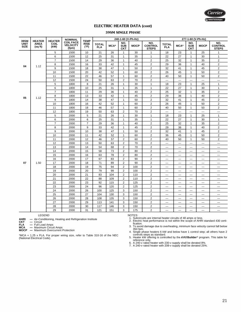
ELECTRIC HEATER DATA (cont)
39SM SINGLE PHASE
LEGEND
*MCA = 1.25 x FLA. For proper wiring size, refer to Table 310-16 of the NEC(National Electrical Code).
NOTES:1. Subcircuits are internal heater circuits of 48 amps or less.2. Electric heat performance is not within the scope of AHRI standard 430 certi-
fication.3. To avoid damage due to overheating, minimum face velocity cannot fall below
350 fpm.4. Single phase heaters 6 kW and below have 1 control step; all others have 2
controls steps as standard.5. Heater kW offering is controlled by the AHUBuilder® program. This table for
reference only.6. A 240-v rated heater with 230-v supply shall be derated 8%.7. A 240-v rated heater with 208-v supply shall be derated 25%.
39SMUNIT SIZE
HEATER AREA (sq ft)
HEATER COIL(kW)
NOMINALCOIL FACEVELOCITY
(fpm)
TEMPRISE(°F)
240-1-60 (V-Ph-Hz) 277-1-60 (V-Ph-Hz)
TOTALFLA MCA*
NO.SUBCKT
MOCPNO.
CONTROLSTEPS
TOTALFLA MCA*
NO.SUBCKT
MOCPNO.
CONTROLSTEPS
04 1.12
5 1500 10 21 26 1 30 1 18 23 1 25 16 1500 12 25 31 1 35 1 22 27 1 30 17 1500 14 29 36 1 40 2 25 32 1 35 28 1500 16 33 42 1 45 2 29 36 1 40 29 1500 18 38 47 1 50 2 32 41 1 45 2
10 1500 20 42 52 1 60 2 26 45 1 50 211 1500 22 46 57 1 60 2 40 50 1 50 212 1500 24 50 63 2 70 2 — — — — —
05 1.12
5 1800 8 21 26 1 30 1 18 23 1 25 16 1800 10 25 31 1 35 1 22 27 1 30 17 1800 11 29 36 1 40 2 25 32 1 35 28 1800 13 33 42 1 45 2 29 36 1 40 29 1800 14 38 47 1 50 2 32 41 1 45 2
10 1800 16 42 52 1 60 2 26 45 1 50 211 1800 18 46 57 1 60 2 40 50 1 50 212 1800 19 50 63 2 70 2 — — — — —
07 1.50
5 2000 5 21 26 1 30 1 18 23 1 25 16 2000 6 25 31 1 35 1 22 27 1 30 17 2000 7 29 36 1 40 2 25 32 1 35 28 2000 9 33 42 1 45 2 29 36 1 40 29 2000 10 38 47 1 50 2 32 41 1 45 2
10 2000 11 42 52 1 60 2 36 45 1 50 211 2000 12 46 57 2 60 2 40 50 1 50 212 2000 13 50 63 2 70 2 — — — — —13 2000 14 54 68 2 70 2 — — — — —14 2000 15 58 73 2 80 2 — — — — —15 2000 16 63 78 2 80 2 — — — — —16 2000 17 67 83 2 90 2 — — — — —17 2000 18 71 89 2 90 2 — — — — —18 2000 19 75 94 2 100 2 — — — — —19 2000 20 79 99 2 100 2 — — — — —20 2000 21 83 104 2 110 2 — — — — —21 2000 22 88 109 2 110 2 — — — — —22 2000 23 92 115 2 125 2 — — — — —23 2000 24 96 120 2 125 2 — — — — —24 2000 26 100 125 3 150 2 — — — — —25 2000 27 104 130 3 150 2 — — — — —26 2000 28 108 135 3 150 2 — — — — —27 2000 29 113 141 3 150 2 — — — — —28 2000 30 117 146 3 150 2 — — — — —29 2000 31 121 151 3 175 2 — — — — —
AHRI — Air-Conditioning, Heating and Refrigeration InstituteCKT — CircuitFLA — Full Load AmpsMCA — Maximum Circuit AmpsMOCP — Maximum Overcurrent Protection

22
ELECTRIC HEATER DATA (cont)
39SM SINGLE PHASE (cont)
LEGEND
*MCA = 1.25 x FLA. For proper wiring size, refer to Table 310-16 of the NEC(National Electrical Code).
NOTES:1. Subcircuits are internal heater circuits of 48 amps or less.2. Electric heat performance is not within the scope of AHRI standard 430 certi-
fication.3. To avoid damage due to overheating, minimum face velocity cannot fall below
350 fpm.4. Single phase heaters 6 kW and below have 1 control step; all others have 2
controls steps as standard.5. Heater kW offering is controlled by the AHUBuilder® program. This table for
reference only.6. A 240-v rated heater with 230-v supply shall be derated 8%.7. A 240-v rated heater with 208-v supply shall be derated 25%.
39SMUNIT SIZE
HEATER AREA (sq ft)
HEATER COIL(kW)
NOMINALCOIL FACEVELOCITY
(fpm)
TEMPRISE(°F)
240-1-60 (V-Ph-Hz) 277-1-60 (V-Ph-Hz)
TOTALFLA MCA*
NO.SUBCKT
MOCPNO.
CONTROLSTEPS
TOTALFLA MCA*
NO.SUBCKT
MOCPNO.
CONTROLSTEPS
09 1.50
5 2700 4 21 26 1 30 1 18 23 1 25 16 2700 5 25 31 1 35 1 22 27 1 30 17 2700 6 29 36 1 40 2 25 32 1 35 28 2700 6 33 42 1 45 2 29 36 1 40 29 2700 7 38 47 1 50 2 32 41 1 45 2
10 2700 8 42 52 1 60 2 36 45 1 50 211 2700 9 46 57 2 60 2 40 50 1 50 212 2700 10 50 63 2 70 2 — — — — —13 2700 10 54 68 2 70 2 — — — — —14 2700 11 58 73 2 80 2 — — — — —15 2700 12 63 78 2 80 2 — — — — —16 2700 13 67 83 2 90 2 — — — — —17 2700 14 71 89 2 90 2 — — — — —18 2700 14 75 94 2 100 2 — — — — —19 2700 15 79 99 2 100 2 — — — — —20 2700 16 83 104 2 110 2 — — — — —21 2700 17 88 109 2 110 2 — — — — —22 2700 18 92 115 2 125 2 — — — — —23 2700 18 96 120 2 125 2 — — — — —24 2700 19 100 125 3 150 2 — — — — —25 2700 20 104 130 3 150 2 — — — — —26 2700 21 108 135 3 150 2 — — — — —27 2700 22 113 141 3 150 2 — — — — —28 2700 22 117 146 3 150 2 — — — — —29 2700 23 121 151 3 175 2 — — — — —
AHRI — Air-Conditioning, Heating and Refrigeration InstituteCKT — CircuitFLA — Full Load AmpsMCA — Maximum Circuit AmpsMOCP — Maximum Overcurrent Protection
Performance data (cont)

23
ELECTRIC HEATER DATA (cont)
39SM 3 PHASE
LEGEND
*MCA = 1.25 x FLA. For proper wiring size, refer to Table 310-16 of the NEC(National Electrical Code).
NOTES:1. Subcircuits are internal heater circuits of 48 amps or less.2. Electric heat performance is not within the scope of AHRI standard 430 certi-
fication.3. To avoid damage due to overheating, minimum face velocity cannot fall below
350 fpm.4. Single phase heaters 6 kW and below have 1 control step; all others have 2
controls steps as standard.5. Heater kW offering is controlled by the AHUBuilder® program. This table for
reference only.6. A 240-v rated heater with 230-v supply shall be derated 8%.7. A 240-v rated heater with 208-v supply shall be derated 25%.
39SMUNIT SIZE
HEATER AREA (sq ft)
HEATER COIL(kW)
NOMINALCOIL FACEVELOCITY
(fpm)
TEMPRISE(°F)
240-3-60 (V-Ph-Hz) 480-3-60 (V-Ph-Hz)
TOTALFLA MCA*
NO.SUBCKT
MOCPNO.
CONTROLSTEPS
TOTALFLA MCA*
NO.SUBCKT
MOCPNO.
CONTROLSTEPS
04 1.12
5 1500 10 12 15 1 20 2 6 8 1 15 26 1500 12 14 18 1 20 2 7 9 1 15 27 1500 14 17 21 1 25 2 8 11 1 15 28 1500 16 19 24 1 25 2 10 12 1 15 29 1500 18 22 27 1 30 2 11 14 1 15 2
10 1500 20 24 30 1 35 2 12 15 1 20 211 1500 22 26 33 1 35 2 13 17 1 20 212 1500 24 29 36 1 40 2 14 18 1 20 2
05 1.12
5 1800 8 12 15 1 20 2 6 8 1 15 26 1800 10 14 18 1 20 2 7 9 1 15 27 1800 11 17 21 1 25 2 8 11 1 15 28 1800 13 19 24 1 25 2 10 12 1 15 29 1800 14 22 27 1 30 2 11 14 1 15 2
10 1800 16 24 30 1 35 2 12 15 1 20 211 1800 18 26 33 1 35 2 13 17 1 20 212 1800 19 29 36 1 40 2 14 18 1 20 2
07 1.50
5 2000 5 12 15 1 20 2 6 8 1 15 26 2000 6 14 18 1 20 2 7 9 1 15 27 2000 7 17 21 1 25 2 8 11 1 15 28 2000 9 19 24 1 25 2 10 12 1 15 29 2000 10 22 27 1 30 2 11 14 1 15 2
10 2000 11 24 30 1 35 2 12 15 1 20 211 2000 12 26 33 1 35 2 13 17 1 20 212 2000 13 29 36 1 40 2 14 18 1 20 213 2000 14 31 39 1 40 2 16 20 1 20 214 2000 15 34 42 1 45 2 17 21 1 25 215 2000 16 36 45 1 50 2 18 23 1 25 216 2000 17 38 48 1 50 2 19 24 1 25 217 2000 18 41 51 1 60 2 20 26 1 30 218 2000 19 43 54 1 60 2 22 27 1 30 219 2000 20 46 57 1 60 2 23 29 1 30 220 2000 21 48 60 2 70 2 24 30 1 35 221 2000 22 51 63 2 70 2 25 32 1 35 222 2000 23 53 66 2 70 2 — — — — —23 2000 24 55 69 2 70 2 — — — — —24 2000 26 58 72 2 80 2 — — — — —25 2000 27 60 75 2 80 2 — — — — —26 2000 28 63 78 2 80 2 — — — — —27 2000 29 65 81 2 90 2 — — — — —28 2000 30 67 84 2 90 2 — — — — —29 2000 31 70 87 2 90 2 — — — — —
AHRI — Air-Conditioning, Heating and Refrigeration InstituteCKT — CircuitFLA — Full Load AmpsMCA — Maximum Circuit AmpsMOCP — Maximum Overcurrent Protection

24
ELECTRIC HEATER DATA (cont)
39SM 3 PHASE (cont)
LEGEND
*MCA = 1.25 x FLA. For proper wiring size, refer to Table 310-16 of the NEC(National Electrical Code).
NOTES:1. Subcircuits are internal heater circuits of 48 amps or less.2. Electric heat performance is not within the scope of AHRI standard 430 certi-
fication.3. To avoid damage due to overheating, minimum face velocity cannot fall below
350 fpm.4. Single phase heaters 6 kW and below have 1 control step; all others have 2
controls steps as standard.5. Heater kW offering is controlled by the AHUBuilder® program. This table for
reference only.6. A 240-v rated heater with 230-v supply shall be derated 8%.7. A 240-v rated heater with 208-v supply shall be derated 25%.
39SMUNIT SIZE
HEATER AREA (sq ft)
HEATER COIL(kW)
NOMINALCOIL FACEVELOCITY
(fpm)
TEMPRISE(°F)
240-3-60 (V-Ph-Hz) 480-3-60 (V-Ph-Hz)
TOTALFLA MCA*
NO.SUBCKT
MOCPNO.
CONTROLSTEPS
TOTALFLA MCA*
NO.SUBCKT
MOCPNO.
CONTROLSTEPS
09 1.50
5 2700 4 12 15 1 20 2 6 8 1 15 26 2700 5 14 18 1 20 2 7 9 1 15 27 2700 6 17 21 1 25 2 8 11 1 15 28 2700 6 19 24 1 25 2 10 12 1 15 29 2700 7 22 27 1 30 2 11 14 1 15 2
10 2700 8 24 30 1 35 2 12 15 1 20 211 2700 9 26 33 1 35 2 13 17 1 20 212 2700 10 29 36 1 40 2 14 18 1 20 213 2700 10 31 39 1 40 2 16 20 1 20 214 2700 11 34 42 1 45 2 17 21 1 25 215 2700 12 36 45 1 50 2 18 23 1 25 216 2700 13 38 48 1 50 2 19 24 1 25 217 2700 14 41 51 1 60 2 20 26 1 30 218 2700 14 43 54 1 60 2 22 27 1 30 219 2700 15 46 57 1 60 2 23 29 1 30 220 2700 16 48 60 2 70 2 24 30 1 35 221 2700 17 51 63 2 70 2 25 32 1 35 222 2700 18 53 66 2 70 2 — — — — —23 2700 18 55 69 2 70 2 — — — — —24 2700 19 58 72 2 80 2 — — — — —25 2700 20 60 75 2 80 2 — — — — —26 2700 21 63 78 2 80 2 — — — — —27 2700 22 65 81 2 90 2 — — — — —28 2700 22 67 84 2 90 2 — — — — —29 2700 23 70 87 2 90 2 — — — — —
AHRI — Air-Conditioning, Heating and Refrigeration InstituteCKT — CircuitFLA — Full Load AmpsMCA — Maximum Circuit AmpsMOCP — Maximum Overcurrent Protection
Performance data (cont)

25
ELECTRIC HEATER DATA (cont)
39SV SINGLE PHASE
LEGEND
*MCA = 1.25 x FLA. For proper wiring size, refer to Table 310-16 of the NEC(National Electrical Code).
NOTES:1. Subcircuits are internal heater circuits of 48 amps or less.2. Electric heat performance is not within the scope of AHRI standard 430 certi-
fication.3. To avoid damage due to overheating, minimum face velocity cannot fall below
350 fpm.4. Single phase heaters 6 kW and below have 1 control step; all others have 2
controls steps as standard.5. Heater kW offering is controlled by the AHUBuilder® program. This table for
reference only.6. A 240-v rated heater with 230-v supply shall be derated 8%.7. A 240-v rated heater with 208-v supply shall be derated 25%.
39SVUNIT SIZE
HEATER AREA (sq ft)
HEATER COIL(kW)
NOMINALCOIL FACEVELOCITY
(fpm)
TEMPRISE(°F)
240-1-60 (V-Ph-Hz) 277-1-60 (V-Ph-Hz)
TOTALFLA MCA*
NO.SUBCKT
MOCPNO.
CONTROLSTEPS
TOTALFLA MCA*
NO.SUBCKT
MOCPNO.
CONTROLSTEPS
02 0.70
1 1200 4 4 5 1 15 1 4 5 1 15 12 1200 8 8 10 1 15 1 7 9 1 15 13 1200 11 13 16 1 20 1 11 14 1 15 14 1200 15 17 21 1 25 1 14 18 1 15 15 1200 19 21 26 1 30 1 18 23 1 15 16 1200 23 25 31 1 35 1 22 27 1 15 17 1200 27 29 36 1 40 2 25 32 1 15 18 1200 31 33 42 1 45 2 29 36 1 15 19 1200 34 38 47 1 50 2 32 41 1 15 2
10 1200 38 42 52 1 60 2 36 45 1 20 2
03 0.70
1 1800 3 4 5 1 15 1 4 5 1 15 12 1800 5 8 10 1 15 1 7 9 1 15 13 1800 8 13 16 1 20 1 11 14 1 15 14 1800 10 17 21 1 25 1 14 18 1 15 15 1800 13 21 26 1 30 1 18 23 1 15 16 1800 15 25 31 1 35 1 22 27 1 15 17 1800 18 29 36 1 40 2 25 32 1 15 18 1800 20 33 42 1 45 2 29 36 1 15 19 1800 23 38 47 1 50 2 32 41 1 15 2
10 1800 25 42 52 1 60 2 36 45 1 20 2
04 0.87
1 1900 2 4 5 1 15 1 4 5 1 15 12 1900 4 8 10 1 15 1 7 9 1 15 13 1900 6 13 16 1 20 1 11 14 1 15 14 1900 8 17 21 1 25 1 14 18 1 20 15 1900 10 21 26 1 30 1 18 23 1 25 16 1900 12 25 31 1 35 1 22 27 1 30 17 1900 13 29 36 1 40 2 25 32 1 35 28 1900 15 33 42 1 45 2 29 36 1 40 29 1900 17 38 47 1 50 2 32 41 1 45 2
10 1900 19 42 52 1 60 2 36 45 1 50 211 1900 21 46 57 1 60 2 40 50 1 50 212 1900 23 50 63 2 70 2 — — — — —13 1900 25 54 68 2 70 2 — — — — —14 1900 27 58 73 2 80 2 — — — — —15 1900 29 63 78 2 80 2 — — — — —16 1900 31 67 83 2 90 2 — — — — —17 1900 33 71 89 2 90 2 — — — — —
AHRI — Air-Conditioning, Heating and Refrigeration InstituteCKT — CircuitFLA — Full Load AmpsMCA — Maximum Circuit AmpsMOCP — Maximum Overcurrent Protection

26
ELECTRIC HEATER DATA (cont)
39SV SINGLE PHASE (cont)
LEGEND
*MCA = 1.25 x FLA. For proper wiring size, refer to Table 310-16 of the NEC(National Electrical Code).
NOTES:1. Subcircuits are internal heater circuits of 48 amps or less.2. Electric heat performance is not within the scope of AHRI standard 430 certi-
fication.3. To avoid damage due to overheating, minimum face velocity cannot fall below
350 fpm.4. Single phase heaters 6 kW and below have 1 control step; all others have 2
controls steps as standard.5. Heater kW offering is controlled by the AHUBuilder® program. This table for
reference only.6. A 240-v rated heater with 230-v supply shall be derated 8%.7. A 240-v rated heater with 208-v supply shall be derated 25%.
39SVUNIT SIZE
HEATER AREA (sq ft)
HEATER COIL(kW)
NOMINALCOIL FACEVELOCITY
(fpm)
TEMPRISE(°F)
240-1-60 (V-Ph-Hz) 277-1-60 (V-Ph-Hz)
TOTALFLA MCA*
NO.SUBCKT
MOCPNO.
CONTROLSTEPS
TOTALFLA MCA*
NO.SUBCKT
MOCPNO.
CONTROLSTEPS
05 1.21
5 1700 8 21 26 1 30 1 18 23 1 25 16 1700 9 25 31 1 35 1 22 27 1 30 17 1700 11 29 36 1 40 2 25 32 1 35 28 1700 12 33 42 1 45 2 29 36 1 40 29 1700 14 38 47 1 50 2 32 41 1 45 2
10 1700 16 42 52 1 60 2 36 45 1 50 211 1700 17 46 57 1 60 2 — — — — —12 1700 19 50 63 2 70 2 — — — — —13 1700 20 54 68 2 70 2 — — — — —14 1700 22 58 73 2 80 2 — — — — —15 1700 23 63 78 2 80 2 — — — — —16 1700 25 67 83 2 90 2 — — — — —17 1700 26 71 89 2 90 2 — — — — —18 1700 28 75 94 2 100 2 — — — — —19 1700 29 79 99 2 100 2 — — — — —
07 1.50
5 2000 5 21 26 1 30 1 18 23 1 25 16 2000 6 25 31 1 35 1 22 27 1 30 17 2000 7 29 36 1 40 2 25 32 1 35 28 2000 9 33 42 1 45 2 29 36 1 49 29 2000 10 38 47 1 50 2 32 41 1 45 2
10 2000 11 42 52 1 60 2 36 45 1 50 211 2000 12 46 57 1 60 2 40 50 1 50 212 2000 13 50 63 2 70 2 — — — — —13 2000 14 54 68 2 70 2 — — — — —14 2000 15 58 73 2 80 2 — — — — —15 2000 16 63 78 2 80 2 — — — — —16 2000 17 67 83 2 90 2 — — — — —17 2000 18 71 89 2 90 2 — — — — —18 2000 19 75 94 2 100 2 — — — — —19 2000 20 79 99 2 100 2 — — — — —20 2000 21 83 104 2 110 2 — — — — —21 2000 22 88 109 2 110 2 — — — — —
09 1.50
5 2700 4 21 26 1 30 1 18 23 1 25 16 2700 5 25 31 1 35 1 22 27 1 30 17 2700 6 29 36 1 40 2 25 32 1 35 28 2700 6 33 42 1 45 2 29 36 1 49 29 2700 7 38 47 1 50 2 32 41 1 45 2
10 2700 8 42 52 1 60 2 36 45 1 50 211 2700 9 46 57 1 60 2 40 50 1 50 212 2700 9 50 63 2 70 2 — — — — —13 2700 10 54 68 2 70 2 — — — — —14 2700 11 58 73 2 80 2 — — — — —15 2700 12 63 78 2 80 2 — — — — —16 2700 13 67 83 2 90 2 — — — — —17 2700 13 71 89 2 90 2 — — — — —18 2700 14 75 94 2 100 2 — — — — —19 2700 15 79 99 2 100 2 — — — — —20 2700 16 83 104 2 110 2 — — — — —21 2700 17 88 109 2 110 2 — — — — —
AHRI — Air-Conditioning, Heating and Refrigeration InstituteCKT — CircuitFLA — Full Load AmpsMCA — Maximum Circuit AmpsMOCP — Maximum Overcurrent Protection
Performance data (cont)

27
ELECTRIC HEATER DATA (cont)
39SV 3 PHASE
LEGEND
*MCA = 1.25 x FLA. For proper wiring size, refer to Table 310-16 of the NEC(National Electrical Code).
NOTES:1. Subcircuits are internal heater circuits of 48 amps or less.2. Electric heat performance is not within the scope of AHRI standard 430 certi-
fication.3. To avoid damage due to overheating, minimum face velocity cannot fall below
350 fpm.4. Single phase heaters 6 kW and below have 1 control step; all others have 2
controls steps as standard.5. Heater kW offering is controlled by the AHUBuilder® program. This table for
reference only.6. A 240-v rated heater with 230-v supply shall be derated 8%.7. A 240-v rated heater with 208-v supply shall be derated 25%.
39SVUNIT SIZE
HEATER AREA (sq ft)
HEATER COIL(kW)
NOMINALCOIL FACEVELOCITY
(fpm)
TEMPRISE(°F)
240-3-60 (V-Ph-Hz) 480-3-60 (V-Ph-Hz)
TOTALFLA MCA*
NO.SUBCKT
MOCPNO.
CONTROLSTEPS
TOTALFLA MCA*
NO.SUBCKT
MOCPNO.
CONTROLSTEPS
02 0.70
1 1200 4 2 3 1 15 2 1 2 1 15 22 1200 8 5 6 1 15 2 2 3 1 15 23 1200 11 7 9 1 15 2 4 5 1 15 24 1200 15 10 12 1 15 2 5 6 1 15 25 1200 19 12 15 1 20 2 6 8 1 15 26 1200 23 14 18 1 20 2 7 9 1 15 27 1200 27 17 21 1 25 2 8 11 1 15 28 1200 31 19 24 1 25 2 10 12 1 15 29 1200 34 22 27 1 30 2 11 14 1 15 2
10 1200 38 24 30 1 35 2 12 15 1 20 2
03 0.70
1 1800 3 2 3 1 15 2 1 2 1 15 22 1800 5 5 6 1 15 2 2 3 1 15 23 1800 8 7 9 1 15 2 4 5 1 15 24 1800 10 10 12 1 15 2 5 6 1 15 25 1800 13 12 15 1 20 2 6 8 1 15 26 1800 15 14 18 1 20 2 7 9 1 15 27 1800 18 17 21 1 25 2 8 11 1 15 28 1800 20 19 24 1 25 2 10 12 1 15 29 1800 23 22 27 1 30 2 11 14 1 15 2
10 1800 25 24 30 1 35 2 12 15 1 20 2
04 0.87
1 1900 2 4 5 1 15 1 — — — — —2 1900 4 8 10 1 15 1 — — — — —3 1900 6 13 16 1 20 1 4 5 1 15 24 1900 8 17 21 1 25 1 5 6 1 15 25 1900 10 21 26 1 30 1 6 8 1 15 26 1900 12 25 31 1 35 1 7 9 1 15 27 1900 13 29 36 1 40 2 8 11 1 15 28 1900 15 33 42 1 45 2 10 12 1 15 29 1900 17 38 47 1 50 2 11 14 1 15 2
10 1900 19 42 52 1 60 2 12 15 1 20 211 1900 21 46 57 1 60 2 13 17 1 20 212 1900 23 50 63 2 70 2 14 18 1 20 213 1900 25 54 68 2 70 2 16 20 1 20 214 1900 27 58 73 2 80 2 17 21 1 25 215 1900 29 63 78 2 80 2 18 23 1 25 216 1900 31 67 83 2 90 2 19 24 1 25 217 1900 33 71 89 2 90 2 20 26 1 30 2
AHRI — Air-Conditioning, Heating and Refrigeration InstituteCKT — CircuitFLA — Full Load AmpsMCA — Maximum Circuit AmpsMOCP — Maximum Overcurrent Protection

28
ELECTRIC HEATER DATA (cont)
39SV 3 PHASE (cont)
LEGEND
*MCA = 1.25 x FLA. For proper wiring size, refer to Table 310-16 of the NEC(National Electrical Code).
NOTES:1. Subcircuits are internal heater circuits of 48 amps or less.2. Electric heat performance is not within the scope of AHRI standard 430 certi-
fication.3. To avoid damage due to overheating, minimum face velocity cannot fall below
350 fpm.4. Single phase heaters 6 kW and below have 1 control step; all others have 2
controls steps as standard.5. Heater kW offering is controlled by the AHUBuilder® program. This table for
reference only.6. A 240-v rated heater with 230-v supply shall be derated 8%.7. A 240-v rated heater with 208-v supply shall be derated 25%.
39SVUNIT SIZE
HEATER AREA (sq ft)
HEATER COIL(kW)
NOMINALCOIL FACEVELOCITY
(fpm)
TEMPRISE(°F)
240-3-60 (V-Ph-Hz) 480-3-60 (V-Ph-Hz)
TOTALFLA MCA*
NO.SUBCKT
MOCPNO.
CONTROLSTEPS
TOTALFLA MCA*
NO.SUBCKT
MOCPNO.
CONTROLSTEPS
05 1.21
5 1700 8 12 15 1 20 2 6 8 1 15 26 1700 9 14 18 1 20 2 7 9 1 15 27 1700 11 17 21 1 25 2 8 11 1 15 28 1700 12 19 24 1 25 2 10 12 1 15 29 1700 14 22 27 1 30 2 11 14 1 15 2
10 1700 16 24 30 1 35 2 12 15 1 20 211 1700 17 26 33 1 35 2 13 17 1 20 212 1700 19 29 36 1 40 2 14 18 1 20 213 1700 20 31 39 1 40 2 16 20 1 20 214 1700 22 34 42 1 45 2 17 21 1 25 215 1700 23 36 45 1 50 2 18 23 1 25 216 1700 25 38 48 1 50 2 19 24 1 25 217 1700 26 41 51 1 60 2 20 26 1 30 218 1700 28 43 54 1 60 2 22 27 1 30 219 1700 29 46 57 1 60 2 23 29 1 30 2
07 1.50
5 2000 5 12 15 1 20 2 6 8 1 15 26 2000 6 14 18 1 20 2 7 9 1 15 27 2000 7 17 21 1 25 2 8 11 1 15 28 2000 9 19 24 1 25 2 10 12 1 15 29 2000 10 22 27 1 30 2 11 14 1 15 2
10 2000 11 24 30 1 35 2 12 15 1 20 211 2000 12 26 33 1 35 2 13 17 1 20 212 2000 13 29 36 1 40 2 14 18 1 20 213 2000 14 31 39 1 40 2 16 20 1 20 214 2000 15 34 42 1 45 2 17 21 1 25 215 2000 16 36 45 1 50 2 18 23 1 25 216 2000 17 38 48 1 50 2 19 24 1 25 217 2000 18 41 51 1 60 2 20 26 1 30 218 2000 19 43 54 1 60 2 22 27 1 30 219 2000 20 46 57 1 60 2 23 29 1 30 220 2000 21 48 60 2 70 2 24 30 1 35 221 2000 22 51 63 2 70 2 25 32 1 35 2
09 1.50
5 2700 4 12 15 1 20 2 6 8 1 15 26 2700 5 14 18 1 20 2 7 9 1 15 27 2700 6 17 21 1 25 2 8 11 1 15 28 2700 6 19 24 1 25 2 10 12 1 15 29 2700 7 22 27 1 30 2 11 14 1 15 2
10 2700 8 24 30 1 35 2 12 15 1 20 211 2700 9 26 33 1 35 2 13 17 1 20 212 2700 9 29 36 1 40 2 14 18 1 20 213 2700 10 31 39 1 40 2 16 20 1 20 214 2700 11 34 42 1 45 2 17 21 1 25 215 2700 12 36 45 1 50 2 18 23 1 25 216 2700 13 38 48 1 50 2 19 24 1 25 217 2700 13 41 51 1 60 2 20 26 1 30 218 2700 14 43 54 1 60 2 22 27 1 30 219 2700 15 46 57 1 60 2 23 29 1 30 220 2700 16 48 60 2 70 2 24 30 1 35 221 2700 17 51 63 2 70 2 25 32 1 35 2
AHRI — Air-Conditioning, Heating and Refrigeration InstituteCKT — CircuitFLA — Full Load AmpsMCA — Maximum Circuit AmpsMOCP — Maximum Overcurrent Protection
Performance data (cont)
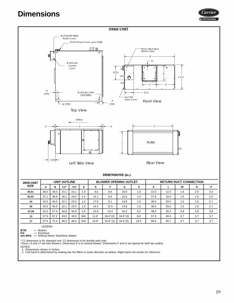
29
DIMENSIONS (in.)
LEGEND
* C1 dimension is for standard unit. C2 dimension is for double-wall units.†Sizes 13 and 17 are twin blowers. Dimension E is to closest blower. Dimensions F and G are typical for both fan outlets.NOTES:1. Dimensions shown in inches.2. Unit hand is determined by looking into the filters in same direction as airflow. Right hand unit shown for reference.
39SH UNIT SIZE
UNIT OUTLINE BLOWER OPENING OUTLET RETURN DUCT CONNECTION
A B C1* C2* D E F G H K L m N P
00,01 38.0 28.0 14.1 15.1 1.0 9.6 8.6 10.6 1.0 22.0 12.3 1.6 2.6 3.3
02,03 37.1 36.6 18.1 19.0 1.0 14.1 8.4 10.6 1.0 27.6 16.4 1.5 1.5 2.9
04 42.0 45.0 22.1 23.0 1.0 17.9 9.1 13.8 1.0 36.0 20.0 1.5 1.5 2.7
05 42.0 45.0 22.1 23.0 1.0 14.3 12.5 13.8 1.0 36.0 20.0 1.5 1.5 2.7
07,09 52.5 57.0 34.8 34.8 1.0 21.8 13.4 16.2 9.1 48.0 32.2 2.8 2.8 2.8
13 57.5 67.2 43.0 43.0 N/A 11.4† 16.4† (2) 16.4† (2) 8.0 57.9 40.4 3.7 3.7 3.7
17 57.5 72.3 48.0 48.0 N/A 14.0† 16.4† (2) 16.4† (2) 13.0 66.0 45.7 3.7 3.7 3.7
BTM — BottomKO — Knockoutw/o MSS — Without Motor Start/Stop Station
39SH UNIT
Airflow
Top View
Left Side View
FILTER
Front View
Rear View
L
K
Motor Start/StopStation (opt)
12.51
H
B
C1-2*
F
G
E
8.12
A
6.35
DD
.875 Power Conn. (w/o MSS)
3/4" FPTDrain Conn.
(TYP)P
KO (TYP)(TOP/BTM)
.875(OPP SIDE)
.875
M (TYP)
(TYP)
Power Conn.
N
.875 24VControlConn.
Dimensions
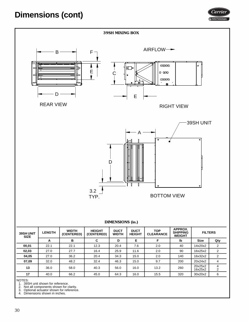
30
AIRFLOW
RIGHT VIEWREAR VIEW
BOTTOM VIEW
39SH UNIT
D
A
3.2TYP.
C
E
E
B
D
F
39SH MIXING BOX
DIMENSIONS (in.)
NOTES:1. 39SH unit shown for reference.2. Not all components shown for clarity.3. Optional actuator shown for reference.4. Dimensions shown in inches.
39SH UNIT SIZE
LENGTH WIDTH(CENTERED)
HEIGHT(CENTERED)
DUCT WIDTH
DUCT HEIGHT
TOP CLEARANCE
APPROX. SHIPPING WEIGHT
FILTERS
A B C D E F lb Size Qty
00,01 22.1 22.1 12.3 20.4 7.6 2.0 40 14x20x2 2
02,03 27.0 27.7 16.4 25.9 11.6 2.0 90 16x25x2 2
04,05 27.0 36.2 20.4 34.3 15.0 2.0 140 16x32x2 2
07,09 32.0 48.2 32.4 46.3 15.0 9.7 200 20x24x2 4
13 36.0 58.0 40.3 56.0 16.0 13.2 260 20x25x216x25x2
42
17 40.0 66.2 45.0 64.3 16.0 15.5 320 30x20x2 6
a39-4121
Dimensions (cont)
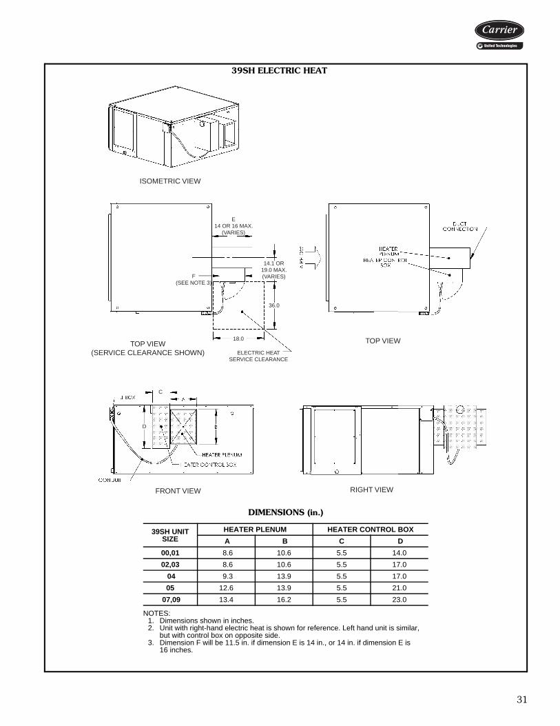
31
ISOMETRIC VIEW
TOP VIEW(SERVICE CLEARANCE SHOWN)
E14 OR 16 MAX.
(VARIES)
14.1 OR19.0 MAX.(VARIES)F
(SEE NOTE 3)
36.0
18.0
ELECTRIC HEATSERVICE CLEARANCE
TOP VIEW
C
D
FRONT VIEW RIGHT VIEWa39-4485
39SH ELECTRIC HEAT
DIMENSIONS (in.)
NOTES:1. Dimensions shown in inches.2. Unit with right-hand electric heat is shown for reference. Left hand unit is similar,
but with control box on opposite side.3. Dimension F will be 11.5 in. if dimension E is 14 in., or 14 in. if dimension E is
16 inches.
39SH UNIT SIZE
HEATER PLENUM HEATER CONTROL BOX
A B C D
00,01 8.6 10.6 5.5 14.0
02,03 8.6 10.6 5.5 17.0
04 9.3 13.9 5.5 17.0
05 12.6 13.9 5.5 21.0
07,09 13.4 16.2 5.5 23.0

32
4 x 4 J-Box (w/o MSS)
F
G
D
12.5
B
E6.3
1.9
Right View
8.22.5
.87524V Control
Conn.
.875 (OPP SIDE)Power Conn.
Motor Start/Stop(MSS) (optional)
Conn.
Liquid Conn. (DX)
Front View
Supply Conn. (CW)
Top View
Supply Conn. (HW)Return (HW) Conn.
Return (CW)Suction (DX)/
Cond Drain w/ Aux (3/4" FPT)
C
A 0.81.5
DIMENSIONS (in.)
LEGEND
NOTE: Dimensions shown in inches.
39SVUNIT SIZE
WIDTH DEPTH HEIGHT SUPPLY DUCT CONNECTION SIZES (OD)
A B C D E F G CWSupply-Return
HWSupply-Return
DXSupply-Return
02 22.3 24.0 50.0 6.9 8.5 3.0 11.8 3/4 - 3/4 7/8 - 7/8 3/8 - 3/403 22.3 24.0 50.0 6.9 8.5 3.0 11.8 3/4 - 3/4 7/8 - 7/8 3/8 - 3/404 25.1 24.3 56.5 8.0 9.1 1.6 13.9 7/8 - 7/8 7/8 - 7/8 1/2 - 7/805 29.5 26.0 59.5 8.4 12.6 1.3 13.9 1 1/8 - 1 1/8 1 1/8 - 1 1/8 1/2 - 1 1/8
CW — Chilled Water MSS — Motor Start/Stop StationDX — Direct Expansion w/o — WithoutHW — Hot Water
39SV UNIT SIZES 02-05 — PRE-HEAT
Dimensions (cont)

33
a39-4486
39SV UNIT SIZE 07 — PRE-HEAT
LEGEND
NOTES:1. Unit section lifting lugs (shipped loose) for lifting sections only. Do not use lifting lugs for lifting
unit assembly. Top lifting lugs may be removed after unit is secured at job site.2. All sections shall be shipped loose and field installed by customer.3. Dimensions shown in inches.
CW — Chilled Water JBOX— Junction BoxHW — Hot Water MSS — Motor Start/Stop Station
w/o — Without
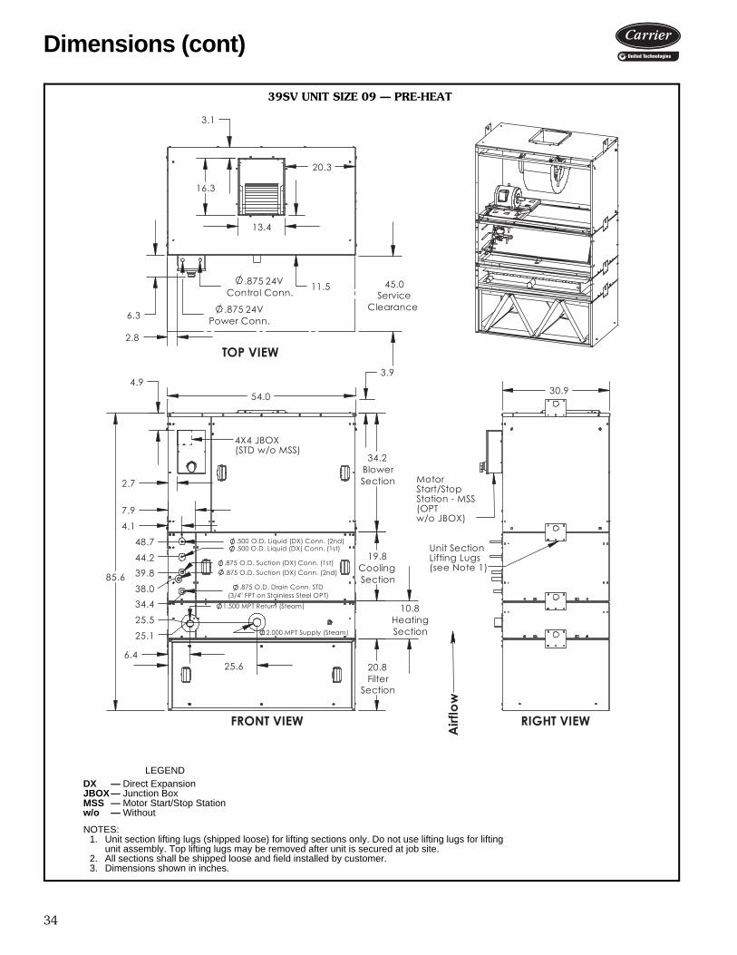
34
a39-4487
39SV UNIT SIZE 09 — PRE-HEAT
LEGEND
NOTES:1. Unit section lifting lugs (shipped loose) for lifting sections only. Do not use lifting lugs for lifting
unit assembly. Top lifting lugs may be removed after unit is secured at job site.2. All sections shall be shipped loose and field installed by customer.3. Dimensions shown in inches.
DX — Direct ExpansionJBOX— Junction BoxMSS — Motor Start/Stop Stationw/o — Without
Dimensions (cont)
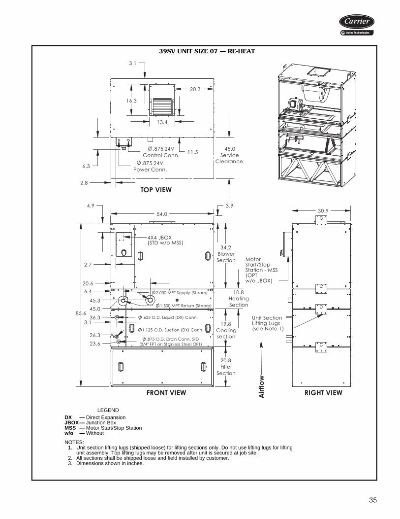
35
a39-4488
39SV UNIT SIZE 07 — RE-HEAT
LEGEND
NOTES:1. Unit section lifting lugs (shipped loose) for lifting sections only. Do not use lifting lugs for lifting
unit assembly. Top lifting lugs may be removed after unit is secured at job site.2. All sections shall be shipped loose and field installed by customer.3. Dimensions shown in inches.
DX — Direct ExpansionJBOX— Junction BoxMSS — Motor Start/Stop Stationw/o — Without
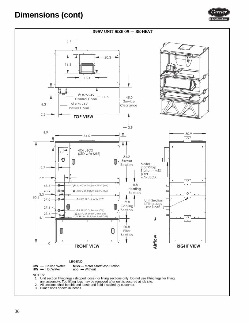
36
a39-4489
39SV UNIT SIZE 09 — RE-HEAT
LEGEND
NOTES:1. Unit section lifting lugs (shipped loose) for lifting sections only. Do not use lifting lugs for lifting
unit assembly. Top lifting lugs may be removed after unit is secured at job site.2. All sections shall be shipped loose and field installed by customer.3. Dimensions shown in inches.
CW — Chilled Water MSS — Motor Start/Stop StationHW — Hot Water w/o — Without
Dimensions (cont)

37
A
D
C
B
EF
a39-4491
(see Note 3)
39SV — FIELD INSTALLED ELECTRIC HEAT
DIMENSIONS (in.)
NOTES:1. Dimensions shown in inches.2. Heater footprint is totally contained within the 39SV unit footprint.3. Dimension F will be 14 in. if dimension E is 12 in., or 16 in. if dimension E is 14 inches.
39SV UNIT SIZEHEATER CONTROL BOX HEATER PLENUM
A B C D
02,03 5.5 20.0 8.8 12.1
04 5.5 22.0 9.3 14.1
05 5.5 24.0 13.1 14.4
07,09 5.5 24.0 13.6 16.5
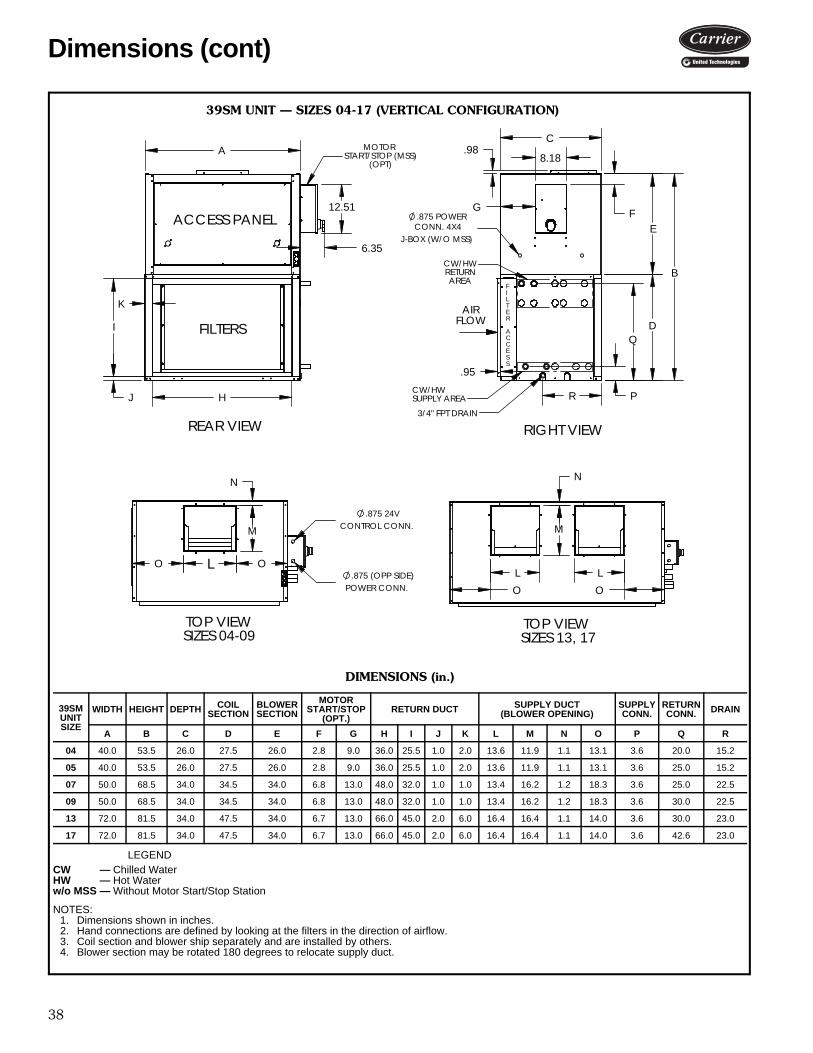
38
39SM UNIT — SIZES 04-17 (VERTICAL CONFIGURATION)
DIMENSIONS (in.)
LEGEND
NOTES: 1. Dimensions shown in inches.2. Hand connections are defined by looking at the filters in the direction of airflow.3. Coil section and blower ship separately and are installed by others.4. Blower section may be rotated 180 degrees to relocate supply duct.
39SM UNIT SIZE
WIDTH HEIGHT DEPTH COIL SECTION
BLOWER SECTION
MOTOR START/STOP
(OPT.)RETURN DUCT SUPPLY DUCT
(BLOWER OPENING)SUPPLY CONN.
RETURN CONN. DRAIN
A B C D E F G H I J K L M N O P Q R
04 40.0 53.5 26.0 27.5 26.0 2.8 9.0 36.0 25.5 1.0 2.0 13.6 11.9 1.1 13.1 3.6 20.0 15.2
05 40.0 53.5 26.0 27.5 26.0 2.8 9.0 36.0 25.5 1.0 2.0 13.6 11.9 1.1 13.1 3.6 25.0 15.2
07 50.0 68.5 34.0 34.5 34.0 6.8 13.0 48.0 32.0 1.0 1.0 13.4 16.2 1.2 18.3 3.6 25.0 22.5
09 50.0 68.5 34.0 34.5 34.0 6.8 13.0 48.0 32.0 1.0 1.0 13.4 16.2 1.2 18.3 3.6 30.0 22.5
13 72.0 81.5 34.0 47.5 34.0 6.7 13.0 66.0 45.0 2.0 6.0 16.4 16.4 1.1 14.0 3.6 30.0 23.0
17 72.0 81.5 34.0 47.5 34.0 6.7 13.0 66.0 45.0 2.0 6.0 16.4 16.4 1.1 14.0 3.6 42.6 23.0
CW — Chilled WaterHW — Hot Waterw/o MSS — Without Motor Start/Stop Station
AIR
FILTERS FLOW
MOTORSTART/STOP (MSS)
(OPT)
H
I
A
K
J
12.51
6.35
VIEWREAR VIEW
SIZES 04-09
RIGHT
TOP VIEW
CONTROL CONN.
O
.875 24V
L
M
O
N
POWER CONN..875 (OPP SIDE)
O
M
LO
L
N
ACCESS PANEL
C
S
AREA
E
SUPPLY AREA
C
RETURN
S
FILTER
A
CW/HW
CW/HW
3/4" FPT DRAIN
G
B
P
.98C
8.18
F
R
Q
.95
D
EJ-BOX (W/O MSS)
.875 POWER CONN. 4X4
TOP VIEWSIZES 13, 17
a39-4075
Dimensions (cont)
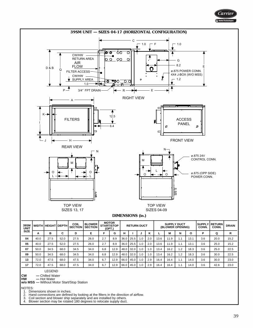
39
DIMENSIONS (in.)
LEGEND
NOTES: 1. Dimensions shown in inches.2. Hand connections are defined by looking at the filters in the direction of airflow.3. Coil section and blower ship separately and are installed by others.4. Blower section may be rotated 180 degrees to relocate supply duct.
39SM UNIT SIZE
WIDTH HEIGHT DEPTH COIL SECTION
BLOWER SECTION
MOTOR START/STOP
(OPT.)RETURN DUCT SUPPLY DUCT
(BLOWER OPENING)SUPPLY CONN.
RETURN CONN. DRAIN
A B C D E F G H I J K L M N O P Q R
04 40.0 27.5 52.0 27.5 26.0 2.7 8.9 36.0 25.5 1.0 2.0 13.6 11.9 1.1 13.1 3.6 20.0 15.2
05 40.0 27.5 52.0 27.5 26.0 2.7 8.9 36.0 25.5 1.0 2.0 13.6 11.9 1.1 13.1 3.6 25.0 15.2
07 50.0 34.5 68.0 34.5 34.0 6.8 12.9 48.0 32.0 1.0 1.0 13.4 16.2 1.2 18.3 3.6 25.0 22.5
09 50.0 34.5 68.0 34.5 34.0 6.8 12.9 48.0 32.0 1.0 1.0 13.4 16.2 1.2 18.3 3.6 30.0 22.5
13 72.0 47.5 68.0 47.5 34.0 6.7 12.9 66.0 45.0 1.0 2.9 16.4 16.4 1.1 14.0 3.6 30.0 23.0
17 72.0 47.5 68.0 47.5 34.0 6.7 12.9 66.0 45.0 1.0 2.9 16.4 16.4 1.1 14.0 3.6 42.6 23.0
CW — Chilled WaterHW — Hot Waterw/o MSS — Without Motor Start/Stop Station
39SM UNIT — SIZES 04-17 (HORIZONTAL CONFIGURATION)
a39-4078

40
DIMENSIONS (in.)
NOTES: 1. Dimensions shown in inches.2. 39SM unit shown for reference only.3. Not all components shown for clarity.4. Optional actuator not shown.5. Top and rear inlets shown. Bottom and rear inlets are also available.
39SM UNIT SIZE
LENGTH WIDTH HEIGHT DUCT WIDTH
DUCT HEIGHT
TOP CLEARANCE FILTERS
A B C D E F SIZE QTY
04,05 27.0 36.2 25.5 34.3 15.0 2.0 16 x 32 x 2 2
07,09 32.0 48.2 32.4 46.3 15.0 9.7 20 x 24 x 2 4
13,17 40.0 66.2 45.0 64.3 16.0 15.5 30 x 20 x 2 6
39SM UNIT — MIXING BOX
a39-4079
Dimensions (cont)

41
M
C
B
L
P
HORIZONTALDISCHARGE (OPT)
G
F
NO
A
4.0
H
DF
G
JK
E
4.0
4.0
DIMENSIONS (in.)
NOTE: Dimensions shown in inches.
39SRUNIT SIZE A B C D E F G H J K L M N O P
02, 03 67.4 39.6 22.5 12.0 25.8 11.9 8.9 11.0 8.0 35.4 14.2 28.4 2.5 15.3 5.604, 05 72.1 48.1 28.5 12.0 34.0 14.1 13.1 11.0 8.0 35.6 18.2 35.8 5.1 17.5 6.207, 09 75.0 53.0 42.2 14.0 44.0 16.4 12.1 15.0 8.0 37.2 24.3 46.0 10.1 20.5 3.5
13 75.1 53.0 55.7 14.0 44.0 16.4 19.4 15.0 8.0 37.3 32.7 46.0 23.5 16.8 3.517 96.0 76.3 53.3 15.0 62.0 19.6 22.0 15.0 8.0 50.3 47.0 68.2 17.4 27.1 4.1
39SR UNIT — SINGLE WALL
a39-4068

42
L
M
C
B
P
A
3.0
4.0
G
4.0
F
D
K
H
J
E
HORIZONTALDISCHARGE (OPT)
G
F
NO
DIMENSIONS (in.)
NOTES:1. Dimensions shown in inches.2. L1 dimension is for horizontal or bottom return economizer package option.3. L2 dimension is for fixed air or manual outside air damper package option.
39SRUNIT SIZE A B C D E F G H J K L1 L2 M N O P
02, 03 70.0 42.0 30.5 12.0 26.0 11.9 8.9 10.0 6.0 33.7 17.2 14.2 28.1 8.5 16.6 7.004, 05 70.4 50.5 33.6 12.0 34.0 14.1 13.4 10.0 6.0 38.9 21.2 18.2 36.1 4.2 18.6 7.207, 09 77.4 55.5 50.9 14.0 44.0 16.4 13.1 15.0 8.0 38.0 35.1 24.3 45.9 19.9 21.2 4.8
13 77.4 55.5 60.6 14.0 44.0 16.4 18.9 15.0 8.0 38.0 48.9 32.8 45.9 29.7 18.3 4.817 96.5 76.5 64.1 14.0 62.0 19.0 22.0 15.0 8.0 51.9 48.2 46.9 65.8 24.0 27.3 5.4
39SR UNIT — DOUBLE WALL
a39-4069
Dimensions (cont)
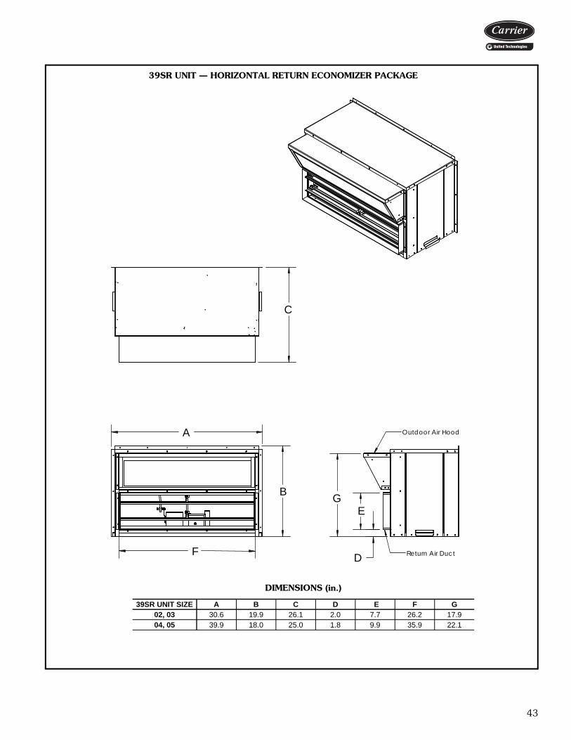
43
B
A
F
Outdoor Air Hood
Return Air Duct
G
D
E
C
39SR UNIT — HORIZONTAL RETURN ECONOMIZER PACKAGE
DIMENSIONS (in.)
39SR UNIT SIZE A B C D E F G02, 03 30.6 19.9 26.1 2.0 7.7 26.2 17.904, 05 39.9 18.0 25.0 1.8 9.9 35.9 22.1
a39-4070

44
E F
Return Air
Outdoor Air
C
D
A
B
39SR UNIT — BOTTOM RETURN ECONOMIZER PACKAGE
DIMENSIONS (in.)
39SR UNIT SIZE A B C D E F02, 03 32.100 18.940 42.075 17.260 25.950 16.15004, 05 39.725 22.825 44.025 21.125 27.750 16.250
a39-4071
Dimensions (cont)
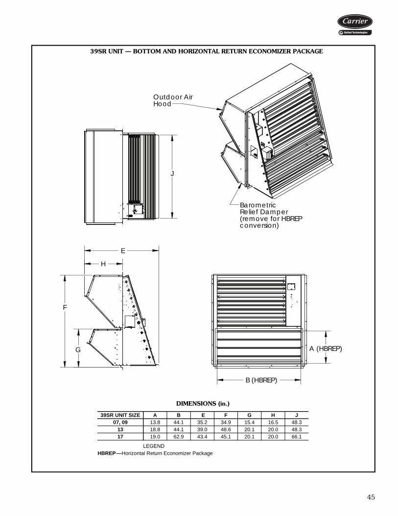
45
39SR UNIT — BOTTOM AND HORIZONTAL RETURN ECONOMIZER PACKAGE
DIMENSIONS (in.)
39SR UNIT SIZE A B E F G H J07, 09 13.8 44.1 35.2 34.9 15.4 16.5 48.3
13 18.8 44.1 39.0 48.6 20.1 20.0 48.317 19.0 62.9 43.4 45.1 20.1 20.0 66.1
LEGENDHBREP—Horizontal Return Economizer Package
E
H
conversion)(remove for HBREP
BarometricRelief Damper
Outdoor AirHood
G
F
B (HBREP)
A (HBREP)
J
a39-4072

46
C
D
E
F
Optional on MOAD
Manual Damper SlideStandard on FAD
Rotating DamperAssemblyStandard on MOADOptional on FAD
HG
A
B
REAR ISOMETRIC VIEW
Actuator (opt)
FRONT ISOMETRIC VIEW
Transformer (opt)
39SR UNIT — FIXED AIR DAMPER/MOTORIZED OUTSIDE AIR DAMPER
FIXED AIR DAMPER DIMENSIONS (in.) MOTORIZED OUTSIDE AIR DAMPER DIMENSIONS (in.)
39SR UNIT SIZE A B C D E F G H
02, 03 28.8 16.1 10.7 5.6 10.3 9.3 12.9 10.104, 05 37.8 20.1 9.8 5.6 15.8 11.0 12.2 8.307, 09 48.8 26.9 14.5 5.6 25.3 11.8 17.6 14.1
13 48.8 34.9 19.4 5.6 21.8 13.5 23.2 19.817 30.3 46.8 18.8 5.6 25.3 2.5 32.9 19.8
39SR UNIT SIZE A B C D E F G H
02, 03 29.9 19.1 8.7 5.6 24.1 2.9 13.4 10.404, 05 37.8 23.5 14.6 5.6 25.3 6.3 17.3 13.807, 09 48.8 28.4 17.4 5.6 44.4 2.2 21.8 19.6
13 48.8 34.9 22.3 5.6 40.5 4.1 28.3 25.817 30.3 46.8 25.0 5.6 25.2 2.5 38.9 31.8
LEGENDFAD — Fixed Air DamperMOAD — Motorized Outside Air Damper
a39-4073
Dimensions (cont)
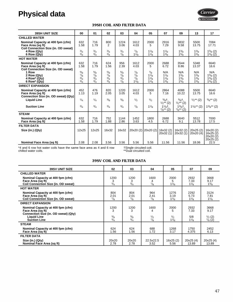
47
39SH COIL AND FILTER DATA
*4 and 6 row hot water coils have the same face area as 4 and 6 rowchilled water coils.
†Single circuited coil.**Dual circuited coil.
39SV COIL AND FILTER DATA
39SH UNIT SIZE 00 01 02 03 04 05 07 09 13 17CHILLED WATER
Nominal Capacity at 400 fpm (cfm) 632 716 800 1224 1612 2000 2916 3832 5500 7084Face Area (sq ft) 1.58 1.79 2 3.06 4.03 5 7.29 9.58 13.75 17.71Coil Connection Size (in. OD sweat)
4 Row (Qty) 3/4 3/4 3/4 3/4 7/8 11/8 11/8 13/8 13/8 15/8 (2) 6 Row (Qty) 3/4 3/4 3/4 7/8 11/8 11/8 13/8 15/8 15/8 15/8 (2)
HOT WATERNominal Capacity at 400 fpm (cfm) 632 716 624 956 1612 2000 2688 3544 5348 6640Face Area (sq ft) 1.58 1.79 1.56 2.39 4.03 5 6.72 8.86 13.37 16.6Coil Connection Size (in. OD sweat)
1 Row 5/8 5/8 5/8 5/8 7/8 7/8 N/A N/A N/A N/A2 Row (Qty) 7/8 7/8 7/8 7/8 7/8 11/8 11/8 13/8 13/8 15/8 (2) 4 Row* (Qty) 3/4 3/4 3/4 3/4 7/8 11/8 11/8 13/8 13/8 15/8 (2)6 Row* (Qty) 3/4 3/4 3/4 7/8 11/8 11/8 13/8 15/8 15/8 15/8 (2)
DIRECT EXPANSIONNominal Capacity at 400 fpm (cfm) 452 476 820 1220 1612 2000 2864 4088 5500 6640Face Area (sq ft) 1.13 1.19 2.05 3.05 4.03 5 7.16 10.22 13.75 16.6Connection Size (in. OD sweat) (Qty)
Liquid Line 1/4 1/4 3/8 3/8 1/2 1/2 5/8†,1/2** (2)
5/8†,1/2** (2)
1/2** (2) 5/8** (2)
Suction Line 3/4 3/4 3/4 3/4 7/8 11/8 11/8†, 7/8** (2)
13/8†,7/8** (2)
11/8** (2) 13/8** (2)
STEAM Nominal Capacity at 400 fpm (cfm) 632 716 752 1144 1452 1800 2688 3640 5512 7000Face Area (sq ft) 1.58 1.79 1.88 2.86 3.63 4.5 6.72 9.1 13.78 17.5
FILTER DATASize (in.) (Qty) 12x25 12x25 16x32 16x32 20x20 (2) 20x20 (2) 16x32 (2)
20x32 (1)16x32 (2)20x32 (1)
20x25 (2)20x20 (4)
16x20 (2)16x25 (2)20x20 (2)20x25 (2)
Nominal Face Area (sq ft) 2.08 2.08 3.56 3.56 5.56 5.56 11.56 11.56 18.06 22.5
39SV UNIT SIZE 02 03 04 05 07 09CHILLED WATER
Nominal Capacity at 400 fpm (cfm) 1200 1200 1600 2000 2932 3668Face Area (sq ft) 3 3 4 5 7.33 9.17Coil Connection Size (in. OD sweat) 3/4 3/4 7/8 11/8 11/8 13/8
HOT WATERNominal Capacity at 400 fpm (cfm) 804 804 964 1276 2292 3124Face Area (sq ft) 2.01 2.01 2.41 3.19 5.73 7.81Coil Connection Size (in. OD sweat) 7/8 7/8 7/8 11/8 11/8 11/8
DIRECT EXPANSIONNominal Capacity at 400 fpm (cfm) 1200 1200 1600 2000 2932 3668Face Area (sq ft) 3 3 4 5 7.33 9.17Connection Size (in. OD sweat) (Qty)
Liquid Line 3/8 3/8 1/2 1/2 5/8 1/2 (2)Suction Line 3/4 3/4 7/8 11/8 11/8 7/8 (2)
STEAMNominal Capacity at 400 fpm (cfm) 624 624 688 1268 1750 2452Face Area (sq ft) 1.56 1.56 1.72 3.17 4.375 6.13
FILTER DATASize (in.) (Qty) 20x20 20x20 22.5x22.5 16x25 (2) 20x25 (4) 20x25 (4)Nominal Face Area (sq ft) 2.78 2.78 3.52 5.56 13.89 13.89
Physical data
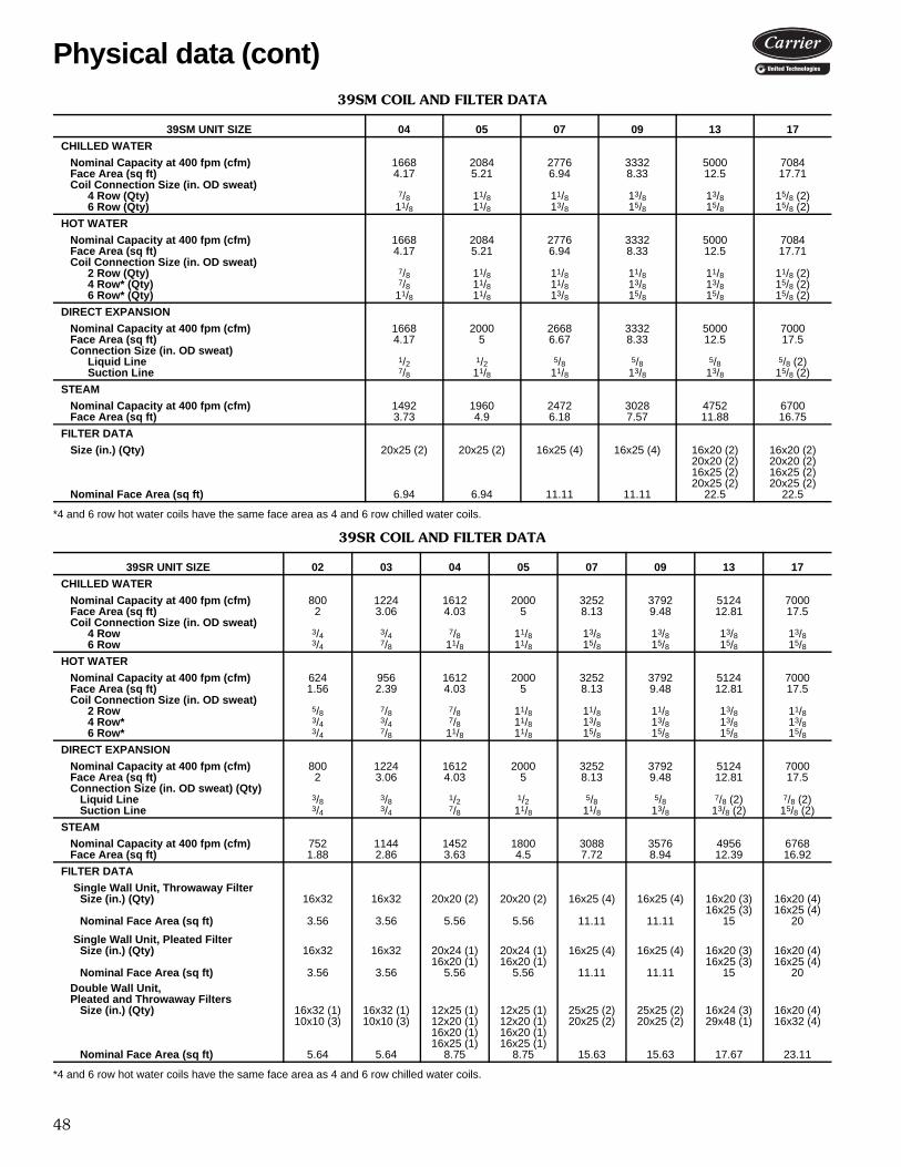
48
39SM COIL AND FILTER DATA
*4 and 6 row hot water coils have the same face area as 4 and 6 row chilled water coils.
39SR COIL AND FILTER DATA
*4 and 6 row hot water coils have the same face area as 4 and 6 row chilled water coils.
39SM UNIT SIZE 04 05 07 09 13 17
CHILLED WATER
Nominal Capacity at 400 fpm (cfm) 1668 2084 2776 3332 5000 7084Face Area (sq ft) 4.17 5.21 6.94 8.33 12.5 17.71Coil Connection Size (in. OD sweat)
4 Row (Qty) 7/8 11/8 11/8 13/8 13/8 15/8 (2)6 Row (Qty) 11/8 11/8 13/8 15/8 15/8 15/8 (2)
HOT WATER
Nominal Capacity at 400 fpm (cfm) 1668 2084 2776 3332 5000 7084Face Area (sq ft) 4.17 5.21 6.94 8.33 12.5 17.71Coil Connection Size (in. OD sweat)
2 Row (Qty) 7/8 11/8 11/8 11/8 11/8 11/8 (2) 4 Row* (Qty) 7/8 11/8 11/8 13/8 13/8 15/8 (2) 6 Row* (Qty) 11/8 11/8 13/8 15/8 15/8 15/8 (2)
DIRECT EXPANSION
Nominal Capacity at 400 fpm (cfm) 1668 2000 2668 3332 5000 7000Face Area (sq ft) 4.17 5 6.67 8.33 12.5 17.5Connection Size (in. OD sweat)
Liquid Line 1/2 1/2 5/8 5/8 5/8 5/8 (2) Suction Line 7/8 11/8 11/8 13/8 13/8 15/8 (2)
STEAM
Nominal Capacity at 400 fpm (cfm) 1492 1960 2472 3028 4752 6700Face Area (sq ft) 3.73 4.9 6.18 7.57 11.88 16.75
FILTER DATA
Size (in.) (Qty) 20x25 (2) 20x25 (2) 16x25 (4) 16x25 (4) 16x20 (2)20x20 (2) 16x25 (2)20x25 (2)
16x20 (2)20x20 (2)16x25 (2)20x25 (2)
Nominal Face Area (sq ft) 6.94 6.94 11.11 11.11 22.5 22.5
39SR UNIT SIZE 02 03 04 05 07 09 13 17
CHILLED WATER
Nominal Capacity at 400 fpm (cfm) 800 1224 1612 2000 3252 3792 5124 7000Face Area (sq ft) 2 3.06 4.03 5 8.13 9.48 12.81 17.5Coil Connection Size (in. OD sweat)
4 Row 3/4 3/4 7/8 11/8 13/8 13/8 13/8 13/86 Row 3/4 7/8 11/8 11/8 15/8 15/8 15/8 15/8
HOT WATER
Nominal Capacity at 400 fpm (cfm) 624 956 1612 2000 3252 3792 5124 7000Face Area (sq ft) 1.56 2.39 4.03 5 8.13 9.48 12.81 17.5Coil Connection Size (in. OD sweat)
2 Row 5/8 7/8 7/8 11/8 11/8 11/8 13/8 11/84 Row* 3/4 3/4 7/8 11/8 13/8 13/8 13/8 13/86 Row* 3/4 7/8 11/8 11/8 15/8 15/8 15/8 15/8
DIRECT EXPANSION
Nominal Capacity at 400 fpm (cfm) 800 1224 1612 2000 3252 3792 5124 7000Face Area (sq ft) 2 3.06 4.03 5 8.13 9.48 12.81 17.5Connection Size (in. OD sweat) (Qty)
Liquid Line 3/8 3/8 1/2 1/2 5/8 5/8 7/8 (2) 7/8 (2)Suction Line 3/4 3/4 7/8 11/8 11/8 13/8 13/8 (2) 15/8 (2)
STEAM
Nominal Capacity at 400 fpm (cfm) 752 1144 1452 1800 3088 3576 4956 6768Face Area (sq ft) 1.88 2.86 3.63 4.5 7.72 8.94 12.39 16.92
FILTER DATA
Single Wall Unit, Throwaway FilterSize (in.) (Qty) 16x32 16x32 20x20 (2) 20x20 (2) 16x25 (4) 16x25 (4) 16x20 (3)
16x25 (3)16x20 (4)16x25 (4)
Nominal Face Area (sq ft) 3.56 3.56 5.56 5.56 11.11 11.11 15 20
Single Wall Unit, Pleated FilterSize (in.) (Qty) 16x32 16x32 20x24 (1)
16x20 (1)20x24 (1)16x20 (1)
16x25 (4) 16x25 (4) 16x20 (3)16x25 (3)
16x20 (4)16x25 (4)
Nominal Face Area (sq ft) 3.56 3.56 5.56 5.56 11.11 11.11 15 20Double Wall Unit, Pleated and Throwaway Filters
Size (in.) (Qty) 16x32 (1)10x10 (3)
16x32 (1)10x10 (3)
12x25 (1)12x20 (1)16x20 (1)16x25 (1)
12x25 (1)12x20 (1)16x20 (1)16x25 (1)
25x25 (2)20x25 (2)
25x25 (2)20x25 (2)
16x24 (3)29x48 (1)
16x20 (4)16x32 (4)
Nominal Face Area (sq ft) 5.64 5.64 8.75 8.75 15.63 15.63 17.67 23.11
Physical data (cont)
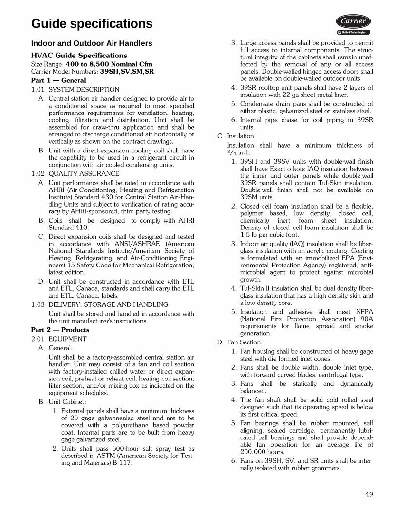
49
Indoor and Outdoor Air Handlers
HVAC Guide Specifications Size Range: 400 to 8,500 Nominal CfmCarrier Model Numbers: 39SH,SV,SM,SRPart 1 — General1.01 SYSTEM DESCRIPTION
A. Central station air handler designed to provide air toa conditioned space as required to meet specifiedperformance requirements for ventilation, heating,cooling, filtration and distribution. Unit shall beassembled for draw-thru application and shall bearranged to discharge conditioned air horizontally orvertically as shown on the contract drawings.
B. Unit with a direct-expansion cooling coil shall havethe capability to be used in a refrigerant circuit inconjunction with air-cooled condensing units.
1.02 QUALITY ASSURANCEA. Unit performance shall be rated in accordance with
AHRI (Air-Conditioning, Heating and RefrigerationInstitute) Standard 430 for Central Station Air-Han-dling Units and subject to verification of rating accu-racy by AHRI-sponsored, third party testing.
B. Coils shall be designed to comply with AHRIStandard 410.
C. Direct expansion coils shall be designed and testedin accordance with ANSI/ASHRAE (AmericanNational Standards Institute/American Society ofHeating, Refrigerating, and Air-Conditioning Engi-neers) 15 Safety Code for Mechanical Refrigeration,latest edition.
D. Unit shall be constructed in accordance with ETLand ETL, Canada, standards and shall carry the ETLand ETL, Canada, labels.
1.03 DELIVERY, STORAGE AND HANDLINGUnit shall be stored and handled in accordance withthe unit manufacturer's instructions.
Part 2 — Products2.01 EQUIPMENT
A. General:Unit shall be a factory-assembled central station airhandler. Unit may consist of a fan and coil sectionwith factory-installed chilled water or direct expan-sion coil, preheat or reheat coil, heating coil section,filter section, and/or mixing box as indicated on theequipment schedules.
B. Unit Cabinet:1. External panels shall have a minimum thickness
of 20 gage galvannealed steel and are to becovered with a polyurethane based powdercoat. Internal parts are to be built from heavygage galvanized steel.
2. Units shall pass 500-hour salt spray test asdescribed in ASTM (American Society for Test-ing and Materials) B-117.
3. Large access panels shall be provided to permitfull access to internal components. The struc-tural integrity of the cabinets shall remain unaf-fected by the removal of any or all accesspanels. Double-walled hinged access doors shallbe available on double-walled outdoor units.
4. 39SR rooftop unit panels shall have 2 layers ofinsulation with 22-ga sheet metal liner.
5. Condensate drain pans shall be constructed ofeither plastic, galvanized steel or stainless steel.
6. Internal pipe chase for coil piping in 39SRunits.
C. Insulation:Insulation shall have a minimum thickness of3/4 inch.
1. 39SH and 39SV units with double-wall finishshall have Exact-o-kote IAQ insulation betweenthe inner and outer panels while double-wall39SR panels shall contain Tuf-Skin insulation.Double-wall finish shall not be available on39SM units.
2. Closed cell foam insulation shall be a flexible,polymer based, low density, closed cell,chemically inert foam sheet insulation.Density of closed cell foam insulation shall be1.5 lb per cubic foot.
3. Indoor air quality (IAQ) insulation shall be fiber-glass insulation with an acrylic coating. Coatingis formulated with an immobilized EPA (Envi-ronmental Protection Agency) registered, anti-microbial agent to protect against microbialgrowth.
4. Tuf-Skin II insulation shall be dual density fiber-glass insulation that has a high density skin anda low density core.
5. Insulation and adhesive shall meet NFPA(National Fire Protection Association) 90Arequirements for flame spread and smokegeneration.
D. Fan Section:1. Fan housing shall be constructed of heavy gage
steel with die-formed inlet cones.2. Fans shall be double width, double inlet type,
with forward-curved blades, centrifugal type.3. Fans shall be statically and dynamically
balanced.4. The fan shaft shall be solid cold rolled steel
designed such that its operating speed is belowits first critical speed.
5. Fan bearings shall be rubber mounted, selfaligning, sealed cartridge, permanently lubri-cated ball bearings and shall provide depend-able fan operation for an average life of200,000 hours.
6. Fans on 39SH, SV, and SR units shall be inter-nally isolated with rubber grommets.
Guide specifications
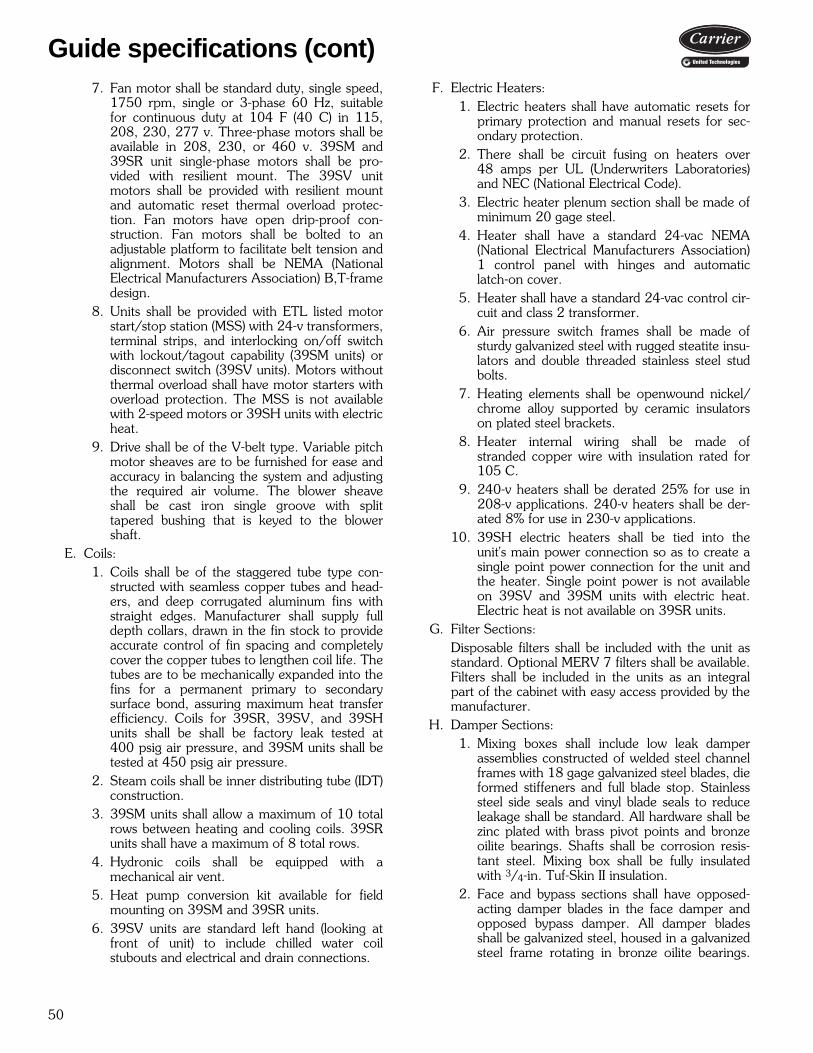
50
7. Fan motor shall be standard duty, single speed,1750 rpm, single or 3-phase 60 Hz, suitablefor continuous duty at 104 F (40 C) in 115,208, 230, 277 v. Three-phase motors shall beavailable in 208, 230, or 460 v. 39SM and39SR unit single-phase motors shall be pro-vided with resilient mount. The 39SV unitmotors shall be provided with resilient mountand automatic reset thermal overload protec-tion. Fan motors have open drip-proof con-struction. Fan motors shall be bolted to anadjustable platform to facilitate belt tension andalignment. Motors shall be NEMA (NationalElectrical Manufacturers Association) B,T-framedesign.
8. Units shall be provided with ETL listed motorstart/stop station (MSS) with 24-v transformers,terminal strips, and interlocking on/off switchwith lockout/tagout capability (39SM units) ordisconnect switch (39SV units). Motors withoutthermal overload shall have motor starters withoverload protection. The MSS is not availablewith 2-speed motors or 39SH units with electricheat.
9. Drive shall be of the V-belt type. Variable pitchmotor sheaves are to be furnished for ease andaccuracy in balancing the system and adjustingthe required air volume. The blower sheaveshall be cast iron single groove with splittapered bushing that is keyed to the blowershaft.
E. Coils:1. Coils shall be of the staggered tube type con-
structed with seamless copper tubes and head-ers, and deep corrugated aluminum fins withstraight edges. Manufacturer shall supply fulldepth collars, drawn in the fin stock to provideaccurate control of fin spacing and completelycover the copper tubes to lengthen coil life. Thetubes are to be mechanically expanded into thefins for a permanent primary to secondarysurface bond, assuring maximum heat transferefficiency. Coils for 39SR, 39SV, and 39SHunits shall be shall be factory leak tested at400 psig air pressure, and 39SM units shall betested at 450 psig air pressure.
2. Steam coils shall be inner distributing tube (IDT)construction.
3. 39SM units shall allow a maximum of 10 totalrows between heating and cooling coils. 39SRunits shall have a maximum of 8 total rows.
4. Hydronic coils shall be equipped with amechanical air vent.
5. Heat pump conversion kit available for fieldmounting on 39SM and 39SR units.
6. 39SV units are standard left hand (looking atfront of unit) to include chilled water coilstubouts and electrical and drain connections.
F. Electric Heaters:1. Electric heaters shall have automatic resets for
primary protection and manual resets for sec-ondary protection.
2. There shall be circuit fusing on heaters over48 amps per UL (Underwriters Laboratories)and NEC (National Electrical Code).
3. Electric heater plenum section shall be made ofminimum 20 gage steel.
4. Heater shall have a standard 24-vac NEMA(National Electrical Manufacturers Association)1 control panel with hinges and automaticlatch-on cover.
5. Heater shall have a standard 24-vac control cir-cuit and class 2 transformer.
6. Air pressure switch frames shall be made ofsturdy galvanized steel with rugged steatite insu-lators and double threaded stainless steel studbolts.
7. Heating elements shall be openwound nickel/chrome alloy supported by ceramic insulatorson plated steel brackets.
8. Heater internal wiring shall be made ofstranded copper wire with insulation rated for105 C.
9. 240-v heaters shall be derated 25% for use in208-v applications. 240-v heaters shall be der-ated 8% for use in 230-v applications.
10. 39SH electric heaters shall be tied into theunit's main power connection so as to create asingle point power connection for the unit andthe heater. Single point power is not availableon 39SV and 39SM units with electric heat.Electric heat is not available on 39SR units.
G. Filter Sections:Disposable filters shall be included with the unit asstandard. Optional MERV 7 filters shall be available.Filters shall be included in the units as an integralpart of the cabinet with easy access provided by themanufacturer.
H. Damper Sections:1. Mixing boxes shall include low leak damper
assemblies constructed of welded steel channelframes with 18 gage galvanized steel blades, dieformed stiffeners and full blade stop. Stainlesssteel side seals and vinyl blade seals to reduceleakage shall be standard. All hardware shall bezinc plated with brass pivot points and bronzeoilite bearings. Shafts shall be corrosion resis-tant steel. Mixing box shall be fully insulatedwith 3/4-in. Tuf-Skin II insulation.
2. Face and bypass sections shall have opposed-acting damper blades in the face damper andopposed bypass damper. All damper bladesshall be galvanized steel, housed in a galvanizedsteel frame rotating in bronze oilite bearings.
Guide specifications (cont)

51
Dampers shall be sectionalized to limit bladelength so as to minimize blade warpage.
I. Economizer Packages:1. Economizers shall include weather hood and
low-leak damper assemblies constructed of steelchannel frames with 18 gage galvanized steelblades, die-formed stiffeners and full blade stop.Stainless steel side seals and vinyl blade seals toreduce leakage shall be standard. All hardwareshall be zinc plated with brass pivot points andbronze oilite bearings. Shafts shall be corrosionresistant steel. Includes motor, enthalpy control,mixed air sensor and transformer relay for208/230/1 volt units. Economizers ship sepa-rate for field assembly to unit.
2. Manual fixed outdoor-air dampers for 0 to 35%or 0 to 100% outdoor air.
3. Motorized fixed outdoor-air damper for 0 to100% outdoor air.
J. Controls:Motor start/stop station shall include a terminalstrip, 24-v Class 2 transformer (75-va), motor relay,contactor, or starter and interlocking disconnect.

Manufacturer reserves the right to discontinue, or change at any time, specifications or designs without notice and without incurring obligations.Pg 52 Catalog No. 04-52390014-01 Printed in U.S.A. Form 39S-4PD
Replaces: 39S-3PD
Carrier Corporation • Syracuse, New York 13221 11-15