product 5f,h compressors data - aireclima.comh-3pd.pdf2 custom-tailored systems to fit your job...
TRANSCRIPT

Copyright 2002 Carrier Corporation Form 5F,H-3PD
Carlyle Series 5F and 5H open-drive compressors, used on Carrier com-pressor units and condensing units, have been the workhorses of the air conditioning and refrigeration indus-try for more than 50 years.Series 5F and 5H are offered as bare compressors and also as factory-assembled compressors, factory-assembled 05FY and 05HY compres-sor units, and factory-assembled 07FY and 07HY condensing units with P701 condensers. Complete sys-tems include motor, drive arrange-ment, control panel, and condenser as required. Or, all components may be ordered as separate sale items for field assembly and installation.
Features/BenefitsThe traditionally high quality of Carlyle 5F and 5H compressors provide effi-cient, reliable operation with unsur-passed performance, whatever theapplication.
Series 5F, 5H StandardFeatures• 3-year compressor warranty• used with most refrigerants• 5 to 150-ton range• high operating efficiency• 50 years of proven reliability• multi-drive application• multi-speed range• multi-motor/voltage combinations• multi-condenser combinations• multi-control-panel designs• factory assembled system or sepa-
rate components for field assembly• 6-week maximum availability
5F,H Compressors05FY,HY Compressor Units07FY,HY Condensing Units
P701 Condensers
5 to 150 Nominal Tons
ProductData
5F,H BARECOMPRESSORS
5F,HBASE-MOUNTEDCOMPRESSORS
05FY,HYCOMPRESSORUNITS
07FY,HYCONDENSINGUNITS
5F, 5H COMPRESSORS

2
Custom-tailored systemsTo fit your job requirements, Carrier compressor and condensing units and Carlyle open-drive compressors are available in any combination. Custom-ized selection enables you to order one factory-assembled system that fits your application, regardless of strict specifi-cations and special power needs. For field installation, you can also select bare or base-mounted compressors and order the balance of the system components as separate items or sup-ply your own.Select quality by ordering:• 5F and 5H Bare Compressors• 5F and 5H Base-Mounted
Compressors• 05FY and 05HY Compressor Units• 07FY and 07HY Condenser Units
The 5F,H compressorsUse the 5F,H line of open compressors to build a system tailored to your equipment needs. These compressors come in 12 sizes, ranging from 5 to 150 tons of cooling, so you can select just the configuration you need. The compressor’s “building block” design lets you choose water-cooled, air-cooled, or evaporative condensers.
The 5F,H compressors can useRefrigerants 134a, 22 or 507/404A. The compressor base accommodates several motor sizes, with either belt or direct drive, to fill both refrigerant and job requirements.
Consider these additional advantag-es when choosing a 5F,H compressor:
Save on first costs:• With automatic, unloaded starting,
expensive high-torque motors are unnecessary, reducing your initial expense.
Save on operating costs:• The design of the crankcase casting
cylinder heads and valve plates allows a smooth, unrestricted refrig-erant flow through the compressor, resulting in greater operating efficiency.
• As suction pressure changes, capac-ity control automatically reduces compressor capacity to as low as 25% of full design load, reducing horsepower requirements and demand charges. This part-load
operation, in turn, increases energy efficiency and lowers utility bills.Internal pressure capacity control is
standard on 5F40-5H126 units. Exter-nal unloading, either pneumatic or electric, can also be special ordered. The 5F20 and 5F30 units offer exter-nal pressure unloading as an accessory feature.
Save on maintenance costs:• A large-capacity, manually revers-
ible oil pump, an automatic pressure regulator, and an oil-filtering system provide positive pressure lubrica-tion for extended compressor life.
• On all units, the oil passes through a fine-mesh screen before reaching the oil pump. A full-flow filter,standard equipment on 5H120, 126 units, ensures clean flow of the large-volume oil charge in these compressors.
• Suction gases stay in contact with cylinder sleeve to keep oil cool and reduce cylinder wear.
• Simple field maintenance and replacement of components such as cylinder liners, pistons, and bearings minimize field service costs and equipment downtime.
• A refined, 2-piece shaft/seal assem-bly virtually eliminates seal leakage. Its carbon ring and neoprene bel-lows combine to provide a tight seal against a highly polished seat. An oil bath completely surrounds the seal assembly, yielding maximum reli-ability over a wide temperature range.
• Efficient crankcase heater design prevents both accumulation of liquid refrigerant in the crankcase during shutdown and the consequent dilu-tion of the compressor’s oil supply.
7 — Oil-Level Sight Glass8 — Oil Drain9 — Reversible Oil Pump
10 — Statically and DynamicallyBalanced Crankshaft
11 — Unrestrictive Suction Gas Inlet
1 — Fine Mesh Suction Screen2 — Precision-Ground Valve Plate Assembly
with Swedish Steel Ring Valves3 — Internal Capacity Control System4 — Time-Proven Shaft Assembly5 — Removable Cylinder Liners6 — Forged-Steel Connection Rods with
Replaceable Bearing Inserts

3
The P701 water-cooled condensersTotaline P701 water-cooled condens-ers are specifically designed for appli-cations where high efficiency is desired and economy is a prime consideration. These condensers offer you maximum adaptability in most comfort and pro-cess cooling applications. Availablesizes range in capacity from 5 to400 tons of heat rejection and are all shell-and-tube type condensers. Each can be custom-matched with compres-sors charged with your choice ofRefrigerants 134a, 22, or 507/404A.
The P701 condensers serve as re-frigerant reservoirs when a system is not operating, eliminating the need for separate receivers.
P701 CX condensers offer the following features:• Small condenser models for fresh
water applications• Tubes made of high performance
copper with enhanced design, roller expanded into multiple-grooved tube sheet
• Flange quality steel tube sheet preci-sion machined for superior sealing
• Condenser heads constructed of nodular iron offer multi-pass design for controlled cooling water velocity
• All water side connections are female pipe thread
• The refrigerant side is constructed to the latest edition of the ASME Section VIII Div 1 code and stamped accordingly
• Refrigerant side pressure is designed for 350 PSI minimum at 250 F
• Water side design pressure is 300 PSI minimum at 150 F
P701 AX condensers offer the following features:• Large condenser models for fresh
water applications• Tubes made of high performance
copper with enhanced design, roller expanded into multiple-grooved tube sheet
• Flange quality steel tube sheet preci-sion machined for superior sealing
• Condenser heads are cast iron or fabricated steel
• All water side connections are female pipe thread except 12 in., 14 in. and 16 in. which have flanges
• Adjustable nozzles for ease of packaging
• The refrigerant side is constructed to the latest edition of the ASME Section VIII Div 1 code and stamped accordingly
• Refrigerant side pressure is designed for 350 PSI at 250 F
• Water side design pressure is 150 PSI at 150 F
Marine condensers offer the following features:• Special order condensers for sea
water or brackish water applications• Tubes made of 90% copper, 10%
nickel with high performance enhanced design, roller expanded into grooved tube sheet
• Tube sheet made of 90% copper, 10% nickel and precision machined for superior sealing
• Condenser heads constructed of cast bronze to withstand corrosive effects of sea water
• Single pass 14 in. and 16 in. heads are fabricated from steel and are epoxy coated
• All water side connections are female pipe thread except 12 in., 14 in. and 16 in. which have flanges
• The refrigerant side is constructed to the latest edition of the ASME Section VIII Div 1 code and stamped accordingly
• Refrigerant side is dual rated for 450 PSI at 150 F or 350 PSI at 250 F
• Water side design pressure is 150 PSI at 150 F
Compressor and condensing unitsFrom a wide selection of compressors, condensers, and accessories, Carrier now provides a completely factory-assembled compressor unit that you can combine with either a remote con-denser or a factory-assembled con-densing unit. Included in the factory-assembled compressor units (05FY, 05HY) are the compressor, steel base, motor, control panel, and accessories. The factory-assembled condensing units (07FY,07HY) consist of all fea-tures of the compressor unit above plus a condenser. On both the factory-assembled compressor unit and the condensing unit, the required intercon-necting wiring is included to minimize field start-up time and costs. Thefactory-assembled condensing units also include the interconnectingpiping.
Table of contentsPage
Features/Benefits . . . . . . . . . . . . . . . . . . . . . . . . . . . . . . . . . . . . . . . . . . .1-3Model Number Nomenclature . . . . . . . . . . . . . . . . . . . . . . . . . . . . . . . . . . . 4Physical Data and Dimensions . . . . . . . . . . . . . . . . . . . . . . . . . . . . . . . . .5-10Field-Installed Accessories . . . . . . . . . . . . . . . . . . . . . . . . . . . . . . . . . . . . . 11Selection Procedure . . . . . . . . . . . . . . . . . . . . . . . . . . . . . . . . . . . . . . .12,13Performance Data . . . . . . . . . . . . . . . . . . . . . . . . . . . . . . . . . . . . . . . .13-24Typical Piping and Wiring . . . . . . . . . . . . . . . . . . . . . . . . . . . . . . . . . . . . . 25Guide Specifications . . . . . . . . . . . . . . . . . . . . . . . . . . . . . . . . . . . . . . .26,27
Features/Benefits (cont)

4
COMPONENT PARTS
NOTES:1. All units operate at 1750 rpm.2. All components require final alignment in the field (at job site).3. Electrical panel control voltage 115-1-60. Transformer not supplied.4. All units are supplied with across-the-line starting.
Co
mp
ress
or
Ste
el b
ase
Co
nd
ense
r
Co
mp
ress
or
mo
tor
Mo
tor
star
ter
Co
ntr
ol p
anel
Sh
uto
ff v
alve
s
Wat
er-c
oo
led
hea
ds
Wat
er-c
oo
led
oil
coo
ler
Cap
acit
y co
ntr
ol
Cra
nkc
ase
equ
aliz
ers
Eq
ual
izer
cov
erp
late
s
Cra
nkc
ase
hea
ters
Cra
nkc
ase
hea
ter
rela
y
Co
mp
r in
tern
al r
elie
f va
lve
Oil
safe
ty s
wit
ch
Du
al p
ress
ure
sw
itch
Fu
ll-fl
ow o
il fi
lter
Par
tial
-flo
w o
il fi
lter
Mu
ffle
rs
Bel
t g
uar
d
Mo
tor
pu
lley
and
bel
ts
Co
mp
ress
or
flyw
hee
l
Co
up
ling
Co
up
ling
gu
ard
Mo
tor
fast
enin
g s
et
Vib
rati
on
iso
lato
rs
BARE COMPRESSOR
5F20, 5F305F405F605H40-5H865H120, 5H126
BASE-MOUNTEDCOMPRESSOR
DirectDrive
5F405F605H40-5H865H120, 5H126
BeltDrive
5F20, 5F305F405F605H40-5H805H120
COMPRESSORUNITS
DirectDrive
05FY04005FY06005HY040-05HY08605HY120-05HY126
BeltDrive
05FY020, 05FY03005FY04005FY06005HY040-05HY08005HY120
CONDENSINGUNITS
DirectDrive
07FY04007FY06007HY040-07HY08607HY120, 07HY126
BeltDrive
07FY020, 07FY03007FY04007FY06007HY040-07HY08007HY120
Included with units.
Available as accessories.
Not included.
Model number nomenclature
ProductModification
05 HY – 080 D K – 401 – – – –
Type of Unit05 – Compressor07 – Condenser
V-Ph-Hz101 – 575-3-60401 – 208-3-60501 – 230-3-60601 – 460-3-60
Motor HorsepowerB – 7-1/2 G – 30 L – 75C – 10 H – 40 M – 100D – 15 J – 50 N – 125E – 20 K – 60 P – 150F – 25
Type of CompressorFY – 5F CompressorHY – 5H Compressor
Compressor (Refer toBare Compressor Datain Physical Data andDimensions Section)
Drive TypeD – DirectB – Belt

5
BARE COMPRESSORS
LEGEND
COMPRESSOR5F 5H 5H
20 30 40 60 40 60 80 120 46 66 86 126OPER WT (lb) 175 215 355 400 610 795 1115 1580 610 795 1115 1580COMPRESSOR
Nom Hp 3-10 5-15 7.5-20 10-30 20-50 30-75 40-100 60-150 40-60 60-100 75-125 125-200Displ Cfm at 1750 Rpm 19.0 29.8 39.8 59.6 92.4 138.4 184.7 276.8 115.5 173.0 231.0 346.0Cylinders 2 3 4 6 4 6 8 12 4 6 8 12Oil (pt) 5 5.5 12 13 18 21 41 61 18 21 41 61Bore (in.) 21/2 31/4Stroke (in.) 2 23/4 37/16
Max Rpm 1750Min Rpm 400 (Required for proper lubrication)Min Rpm, Cap. Control 600 700 800 900 800 900 1100 900 800 900 1100 900High-Side Max Pressure 400 psigLow-Side Max Pressure 245 psig
DIMENSIONS (in.)A 157/8 18 211/2 231/2 301/2 311/2 437/8 47 301/2 311/2 437/8 47B 183/4 207/8 19 21 241/2 271/4 241/2 273/8 241/2 271/4 241/2 273/8C 183/4 18 201/8 241/2 29 297/8 32 347/8 29 297/8 32 347/8
Between D 53/4 53/4 12 137/16 151/2 17 29 29 151/2 17 29 29Mtg Hole E 10 10 8 8 11 11 11 11 11 11 11 11
CONNECTIONS (in.)Suction (ODF) 11/8 15/8 15/8 21/8 25/8 31/8 31/8 41/8 25/8 31/8 31/8 41/8Discharge (ODF) 7/8 13/8 13/8 15/8 21/8 31/8 31/8 41/8 21/8 31/8 31/8 41/8
CL
Hp — HorsepowerODF — Outside Diameter Female
Physical data and dimensions
B
EA
D
C

6
Physical data and dimensions (cont)
1/8” NPTVENT
WATEROUTLETH
D
G
WATERINLET H
2” 2”1/8” NPTVENT
WATERCONNECTIONS
7-1/2”
2-7/32”J LIQUID OUTLET (OPPOSITE SIDE)
6-5/8”
1-19/32”
ODF GASINLETI
A
B
E
RELIEFVALVEF
C
P701 CX FRESH WATER CONDENSERS
PHYSICAL DATA AND DIMENSIONS (in.)
LEGEND
UNITP701- A B C D E F
FPT G HFPT
IODF
JODF
WEIGHT(lb)
0605CX 279/16 233/4 31/2 2 163/8 1/2 413/16 1 15/8 11/8 1000607CX 279/16 233/4 31/2 2 163/8 1/2 413/16 1 15/8 11/8 1050610CX 399/16 353/4 31/2 2 283/8 1/2 413/16 11/4 15/8 11/8 1300615CX 519/16 473/4 31/2 2 403/8 1/2 413/16 11/4 15/8 11/8 1600620CX 519/16 473/4 31/2 2 403/8 1/2 413/16 11/4 15/8 11/8 170
FPT — Female Pipe ThreadNPT — National Pipe ThreadODF — Outside Diameter Female

7
A
B
E
GASINLET
F
P
C
WATEROUTLET END(1-PASS ONLY)
SWATEROUTLET
SWATERINLET
KG
J
SWATEROUTLET
SWATERINLET
N
L
R LIQUID OUTLET(OPPOSITE SIDE)
MSAFETY
SWATERINLET
SWATEROUTLET(FAR END)
N
L
G
J
N
L
G
C D
H
WATERCONNECTIONS
1-PASS 2-PASS 4-PASS
P701 AX FRESH WATER CONDENSERS
NOTE: Water inlet is on opposite end.
PHYSICAL DATA AND DIMENSIONS (in.)
LEGEND
*125 lb flat face flange.†150 lb raised face flange.
UNITP701-
ADIA B C D E F G H J L M
FPT N PODF
RODF S WEIGHT
(lb)0625AX 65/8 6313/16 21/32 31/2 523/8 37/8 413/16 71/2 11/2 25/8 1/2 65/16 15/8 11/8 2 1700630AX 65/8 6313/16 21/32 31/2 523/8 37/8 413/16 71/2 11/2 25/8 1/2 65/16 21/8 13/8 2 1950840AX 85/8 66 31/8 31/2 523/8 37/8 513/16 911/16 17/8 313/32
1/2 75/16 21/8 13/8 21/2 3000850AX 85/8 78 31/8 31/2 643/8 37/8 513/16 911/16 17/8 313/32
1/2 75/16 21/8 13/8 21/2 3401065AX 103/4 691/8 411/16 33/4 52 4 67/8 133/4 21/4 41/4 1/2 83/8 25/8 15/8 3 4601075AX 103/4 811/8 411/16 33/4 64 4 67/8 133/4 21/4 41/4 1/2 83/8 25/8 15/8 3 4751290AX 123/4 69 45/8 43/16 5015/16 45/8 77/8 153/4 25/8 51/4 3/4 93/8 25/8 15/8 4 59012110AX 123/4 81 45/8 43/8 627/16 415/16 77/8 153/4 25/8 51/16
3/4 93/8 31/8 21/8 4 66512140AX 123/4 108 61/8 43/8 867/16 415/16 77/8 153/4 — 51/16
3/4 93/8 31/8 21/8 6* 85512150AX 123/4 108 61/8 43/8 867/16 415/16 77/8 153/4 — 51/16
3/4 93/8 31/8 21/8 6* 89012200AX 123/4 132 61/8 43/8 1103/16 53/16 77/8 153/4 — 51/16
3/4 93/8 35/8 21/8 6* 106014140AX 14 69 51/8 43/8 507/16 415/16 81/2 177/8 41/2 59/16
3/4 10 31/8 21/8 4* 89514165AX 14 81 51/8 43/8 627/16 415/16 81/2 177/8 41/2 59/16
3/4 10 35/8 21/8 4* 141014210AX 14 1153/8 911/16 45/8 8511/16 57/16 81/2 177/8 — 57/16
3/4 10 41/8 25/8 6† 124014270AX 14 1393/8 911/16 45/8 10911/16 57/16 81/2 177/8 — 57/16
3/4 10 41/8 25/8 6† 142014290AX 14 1393/8 911/16 45/8 10911/16 57/16 81/2 177/8 — 57/16
3/4 10 41/8 25/8 6† 148016200AX 16 69 51/8 45/8 4911/16 57/16 91/2 197/8 5 61/2 3/4 11 35/8 21/8 5* 122016210AX 16 81 51/8 47/8 613/16 511/16 91/2 197/8 5 67/16
3/4 11 41/8 25/8 5* 119016230AX 16 81 51/8 47/8 613/16 511/16 91/2 197/8 5 67/16
3/4 11 41/8 25/8 5* 136016300AX 16 1201/2 123/8 47/8 845/8 61/4 91/2 197/8 — 57/8 3/4 11 51/8 31/8 8† 172316360AX 16 1441/2 123/8 47/8 1085/8 61/4 91/2 197/8 — 57/8 3/4 11 51/8 31/8 8† 182516400AX 16 1441/2 123/8 47/8 1085/8 61/4 91/2 197/8 — 57/8 3/4 11 51/8 31/8 8† 2085
FPT — Female Pipe ThreadODF — Outside Diameter Female

8
COMPRESSOR UNITS
LEGEND
*Length is 735/8 in. when using a 326T Frame or smaller motor.
NOTES:1. Operating weights include water and refrigerant. Unit is not factory
charged. Weights do NOT include motor.2. Dimensions shown are ±1 in. and are shown with the largest con-
trol box. Actual height and width may be less based on hp and volt-age of control box. Full dimensional drawings available on requestfor standard units. Certified drawings, which are specific to a unitmodel number and show in depth detail, are available at an addi-tional charge.
3. Base-mounted compressor dimensions are in the table on page 10.
COMPRESSOR5F 5H 5H
20 30 40 60 40 60 80 120 46 66 86 126OPER WT (lb)
BD 390 430 645 730 1045 1225 1780 2345 — — — —DD — — 610 695 1010 1195 1840 2340 1010 1195 1840 2340
COMPRESSORNom Hp 3-10 5-15 7.5-20 10-30 20-50 30-75 40-100 60-150 40-60 60-100 75-125 125-200Displ Cfm at 1750 Rpm 19.0 29.8 39.8 59.6 92.4 138.4 184.7 276.8 115.5 173.0 231.0 346.0Cylinders 2 3 4 6 4 6 8 12 4 6 8 12Oil (pt) 5 5.5 12 13 18 21 41 61 18 21 41 61Bore (in.) 21/2 31/4Stroke (in.) 2 23/4 37/16
Max Rpm 1750Min Rpm 400 (Required for proper lubrication)Min Rpm, Cap. Control 600 700 800 900 800 900 1100 900 800 900 1100 900High-Side Max Pressure 400 psigLow-Side Max Pressure 245 psig
DIMENSIONS (in.)BD A 455/8 455/8 61 61 703/8 7115/16 78 80 — — — —
B 23 23 29 29 313/4 323/4 451/8 49 — — — —C 31 31 30 303/4 371/4 38 577/8 46 — — — —
DD A — — 603/4 611/8 7213/16 771/4* 943/4 975/8 7213/16 771/4 943/4 975/8B — — 29 29 29 29 35 35 29 29 35 35C — — 30 303/4 377/8 341/2 46 457/8 377/8 359/16 46 457/8
BD — Belt DriveDD — Direct Drive
Physical data and dimensions (cont)
COMPRESSOR UNIT, DIRECT DRIVE (DD) COMPRESSOR UNIT, BELT DRIVE (BD)

9
CONDENSING UNITS
NOTES:1. Operating weights include water and refrigerant. Unit is not factory charged.
Weights do NOT include motor.
2. Dimensions shown are ±1 and are shown with the largest control box. Actualheight and width may be less based on hp and voltage of control box. Fulldimensional drawings available on request for standard units. Certifieddrawings, which are specific to a unit model number and show in depthdetail, are available at an additional charge.
DRIVE BELT (07FY,HY)COMPR 5F20 5F30 5F40 5F60 5H40 5H60 5H80CONDP701 0610CX 0620CX 0620CX 0625CX 0840AX 0850AX 1065AX 0850AX 1065AX 1290AX 1290AX 12110AX 12140AX 14210AX
OPER WT (lb) 515 555 590 1090 1360 1845 2085 2055 2295 2520 3120 3180 3515 3820A 46 52 52 69 695/8 81 761/2 811/8 765/8 765/8 79 85 1153/8 108B 26 26 26 267/8 267/8 311/2 311/2 327/16 327/16 327/16 441/4 441/4 441/4 441/4C 31 31 31 423/8 49 661/2 661/2 725/8 725/8 725/8 737/8 737/8 737/8 737/8
DRIVE BELT (07FY,HY) (cont)COMPR 5H120CONDP701 1290AX 12110AX 12140AX 14210AX
OPER WT (lb) 3720 3795 4085 4370A 79 85 108 1153/8B 48 48 48 48C 741/8 741/8 741/4 741/4
DRIVE DIRECT (07FY,HY)COMPR 5F40 5F60 5H40 5H46 5H60CONDP701 0625CX 0840AX 0850AX 0850AX 1065AX 1065AX 1290AX 12110AX 1065AX 1290AX 12110AX 12140AX
OPER WT (lb) 1010 1190 1515 1735 2020 2020 2155 2225 2155 2320 2870 2930A 69 70 78 837/8 793/8 793/8 791/4 851/4 793/8 791/4 851/4 108B 25 25 25 301/2 301/2 301/2 301/2 301/2 301/2 301/2 301/2 301/2C 411/4 471/4 471/4 73 73 73 73 73 73 73 73 73
DRIVE DIRECT (07FY,HY) (cont)COMPR 5H66 5H80 5H86CONDP701 1290AX 12110AX 12140AX 14210AX 1290AX 12110AX 12140AX 14210AX 12110AX 12140AX 14210AX 16230AX
OPER WT (lb) 2320 2870 2930 3235 3060 3120 3445 3950 3120 3445 3750 4360A 791/4 851/4 108 116 94 94 108 1153/8 94 108 1153/8 94B 301/2 301/2 301/2 301/2 313/4 313/4 313/4 313/4 313/4 313/4 313/4 313/4C 73 73 73 73 767/8 767/8 747/8 747/8 767/8 747/8 747/8 767/8
DRIVE DIRECT (07FY,HY) (cont)COMPR 5H120 5H126CONDP701 12110AX 12140AX 14210AX 16230AX 14210AX 16230AX
OPER WT (lb) 3700 4000 4260 4870 4260 4870A 975/8 975/8 1153/8 975/8 1153/8 975/8B 41 41 41 41 41 41C 84 84 84 84 84 84
CONDENSING UNIT DIMENSIONS

10
BASE-MOUNTED COMPRESSOR
LEGEND
NOTE: Dimensions shown are ± 1-inch.
COMPRESSOR5F 5H 5H
20 30 40 60 40 60 80 120 46 66 86 126DIMENSIONS (in.)
BD A 381/4 381/4 481/8 481/8 573/4 591/4 651/4 671/8 — — — —B 205/8 205/8 251/8 261/4 311/4 243/8 451/8 48 — — — —C 281/2 281/2 255/8 303/4 371/4 341/16 421/4 431/2 — — — —
DD A — — 481/8 481/4 593/8 607/8 811/2 847/8 593/8 607/8 811/2 847/8B — — 211/2 211/2 241/2 273/8 313/4 313/4 241/2 273/8 313/4 313/4C — — 241/2 303/4 371/4 3315/16 421/4 431/2 371/4 3315/16 421/4 431/2
BD — Belt DriveDD — Direct Drive
Physical data and dimensions (cont)
DIRECT DRIVE UNIT BASES BELT DRIVE UNIT BASES
B width dimension not shown in this view.

11
Enhance your system’s capabilities and performance with the many quality accessories available for the 5F,H line.Carrier control panel (32C) for 05FY, 05HY, 07FY, or 07HY com-pressor and condensing units allows precision monitoring and control of compressor functions such as start-up and operation, oil pressure, and short-cycle protection. Eliminates time-consuming and costly field fabrication. All control panels meet NEMA (National Electrical Manufacturing Association) requirements for enclo-sures (see current literature for details).Water-cooled heads protect com-pressor by keeping heads cool when compression ratios or discharge gas temperatures are high (see ratings).Partial-flow oil filter (available for 5H40 through 5H86 compressors) helps prolong service life of the equip-ment. This filter supplements filtration provided by the fine-mesh screen fur-nished as standard equipment on all compressors.Water-cooled oil cooler removes excessive heat resulting from highly super-heated suction gas or high com-pression ratios to prevent oil break-down and increase life expectancy of compressor and its components.Crankcase equalizer coverplate provides easy points for interconnect-ing gas and oil equalizer lines, for equalizing pressures in compressor crankcases on the same circuit.Couplings connect ends of drive shaft and driven unit, transmit torque, and allow for a small amount of shaft mis-alignment. Couplings prevent damage to bearings and seals and absorb com-pressor vibrations to prolong service life.Belt-drive package (motor pulley, belts, and compressor flywheel) is avail-able for compressor operation at1750 rpm or at 1450 rpm with1750 rpm motors. All components are precision matched to provide opti-mum compressor performance with minimum wear.Crankcase heater and relay (sepa-rate items) prevent refrigerant from diluting oil during shutdown to ensure proper compressor lubrication.Muffler attenuates sound and gas pul-sations, resulting in low sound levels.Vibration isolators prevent trans-mission of vibration to buildingstructure and provide unobtrusiveoperation.Motor fastening set to mount motor to compressor base.
Field-installed accessories
8060
40
200
100 120140160
180200
8060
40
200
100 120140160
180200
100
200
300
400
500
6000
EQUALIZER COVERPLATE
WATER-COOLED OILCOOLER (ACCESSORY) PARTIAL-FLOW OIL
FILTER (ACCESSORY)
200 160
12080
400
CARRIER CONTROL PANEL

12
Performance data is given for Refrigerants 134a, 22, and507/404A for all units.
Compressor unitI Determine job requirements.
Example:Given:Refrigerant . . . . . . . . . . . . . . . . . . . . . . . . . R-22Cooling Load . . . . . . . . . . . . . . . . . . . . . 38 TonsSaturated Suction Temp (SST) . . . . . . . . . . . .40 FSaturated Discharge Temp (SDT) . . . . . . . . .120 F
II Select compressor unit.Enter ratings table for desired refrigerant atthe required suction (SST) and discharge (SDT)temperatures.Example:Enter ratings table for R-22, page 16. Read downthe table under 40 F SST and 120 F SDT to find acompressor with the capacity to meet the 38-tonload requirement. Select a 5H40 compressor.
III Obtain complete compressor performancedata from ratings table.In this example, when selecting a condenser (aircooled or water cooled), it must be able to handlethe Total Heat of Rejection (THR) of 47.5 tons. AllTHR ratings equal 12,000 Btuh/ton. The brakehorsepower (BHP) of the motor required is 44.5and a 50 horsepower motor or larger should bechosen.
IV Consult rating notes for capacity adjustmentfactors which may be required (pages 13,23 and 24).
Condensing unit selectionWhen selecting a condensing unit, the rated compressorcapacity must be corrected to compensate for the availablerefrigerant subcooling. A P701 condenser nominally pro-vides 2F of refrigerant subcooling while the compressorratings are based on 15 F subcooling. The capacity ratingshould be adjusted by .5% for each degree of subcoolingdifference for R-22 and .6% for R-134a or R-507/404A.Since there is a 13 F difference, the capacity mustbe reduced by 6.5% for R-22 or 7.8% for R-134a orR-507/404A.
I Determine job requirements.Example:Given:Refrigerant . . . . . . . . . . . . . . . . . . . . . . . . . R-22Cooling Load . . . . . . . . . . . . . . . . . . . . . 17 TonsSaturated Suction Temp (SST) . . . . . . . . . . . .40 FSaturated Discharge Temp (SDT) . . . . . . . . .105 F
II Select compressor unit.The load requirement must be corrected to utilizethe rating tables for unit selection.Corrected Required Capacity = Required Load/.935Example:Load Requirement = 17 TonsCorrected Required Capacity = 17 Tons/.935
= 18.2 TonsEnter rating table for R-22. Under 40 F SST and105 F SDT, select a 5F40 compressor. This selec-tion meets the job requirements. Use direct interpo-lation where job requirements fall between thevalues shown.
III Correct compressor unit rating for 2 F ofrefrigerant subcooling available from theP701 condenser.Actual Capacity = Rated Capacity x .935Actual THR = Actual Capacity
+ (Rated BHP x .212)**The .212 multiplier is used to determine heat ofcompression (in tons) for an open drive compressor.
Example:Actual Capacity = 18.2 x .935
= 17 TonsActual THR = 17 Tons + (17.3 x .212)
= 17 + 3.7= 20.7 Tons
NOTE: Brake horsepower requirements are notaffected by variations in system subcooling.
IV Corrected compressor unit performance.
V Select condenser.1. Determine the GTD (Greatest Temperature Dif-
ference), which is the temperature differencebetween the entering water temperature and thesaturated discharge temperature. In this example,20 F will be used which is typical.
2. Enter the condenser capacity and flow rate tablesfor the desired GTD and THR. Convert THR toBtuh by multiplying by 12,000. It is recom-mended to stay within the upper third of the con-denser table selected. A P701-0625AXcondenser meets the job requirements.NOTE: See condenser selection recommenda-tions on page 13.
3. The required gpm for this example is 37 and thepressure drop is 1.32 psid.
VI Consult rating notes for capacity adjustmentfactors which may be required (pages 13, 23and 24).
COMPRESSOR PERFORMANCE5H40
SST SDT CAP. BHP THR40 120 38.0 44.5 47.5
COMPR SST SDT CAP. BHP THR5F40 40 105 17 17.3 20.7
Selection procedure (with example)

13
Selection notesCompressor and condensing units
1. Saturated Suction Temperature — The saturatedsuction temperature used in selection of a compressoror condensing unit should be the saturated tempera-ture at the compressor. To obtain proper unit selec-tion, line losses should be considered (suction and/ordischarge line loss).
2. R-22 applications require an oil cooler when (abso-lute) pressure ratio is greater than 5.0; oil cooler andwater-cooled heads required when discharge temper-ature is greater than 250 F.R-134a applications require an oil cooler and water-cooled heads when the discharge temperature isgreater than 275 F.R-507/404A applications require an oil cooler whenthe SST is less than –20 F and require an oil cooler
and water-cooled heads when the discharge tempera-ture is greater than 275 F.
3. Condensing Unit Selection — There are a numberof condensers that may be selected for each compres-sor for each refrigerant listed. Selection of the propercondenser may depend on several factors:a. Water flow rateb. Pumping headc. Condensing unit efficiencyd. First cost
Selecting a larger condenser provides for better opera-tion under adverse conditions such as high condenser foul-ing or high entering-water temperatures. Unit capacity andefficiency can also be increased at nominal flow rates overutilization of a smaller condenser. Final selection should bebased on the present and future job requirements and indi-vidual job economics.
Performance dataRating notesCompressor and condensing units
1. Compressor ratings are based on 1750 rpm and15° F subcooling.
2. Compressor performance must be adjusted for con-densing units which provide a nominal 2° F of refrig-erant subcooling (see Condensing Unit Selection).
3. Refrigerant temperatures shown are saturated tem-peratures corresponding to pressures indicated atcompressor. Actual gas temperatures are higherbecause of superheat.
4. Capacities are based on actual suction gas tempera-tures to the compressor of 65 F for R-134a andR-507/404A (this assumes superheat is obtainedfrom liquid-suction interchanger or in evaporator).Capacity corrections for other than rated suction gastemperatures may be obtained from Rating Basis andCapacity Multipliers table, page 23.
5. Capacities for R-22 are based on 15° F suction gassuperheat, which normally occurs because of expan-sion valve operation and line losses. R-22 ratings canbe used without adjustment.
6. The discharge line loss on all 07FY, 07HY condens-ing units is negligible. The saturated discharge tem-perature (SDT) is therefore equal to the saturatedcondensing temperature (SCT).
7. THR is in tons and equals 12,000 Btuh/ton.
Base condensers1. The capacities listed in the Condenser Capacity and
Flow Rate tables are based on 105 SCT (SaturatedCondensing Temperature). When operating at otherSCTs between 90 F and 135 F, the change in con-denser capacity is minimal. Contact your Carrier Fac-tory Sales Representative for the exact capacity, ifrequired. Also, all the data points available in hardcopy format for R-22 are not available for R-134aand R-507/404A. You can either interpolate or con-tact your Carrier Factory Sales Representative.
2. GPM shown in Condenser Capacity and Flow Ratetables are based on .0005 total fouling factor. Forother fouling factors contact your Carrier FactorySales Representative.
3. Stay within the GPM shown in the tables. A GPMbelow those listed can cause tube fouling and abovethose listed can cause tube erosion.
4. Saturated Condensing Temperature (SCT) = Satu-rated Discharge Temperature (SDT) – Discharge LineLoss (F). Discharge line loss may occur when the con-denser is remote from compressor.
5. Condenser nominal tons equals 14,400 Btuh. Thisequates to 12,000 Btuh/ton at the evaporator plusan additional 20% for heat of compression.

14
CONDENSER CAPACITIES
LEGEND
NOTES:1. Nominal tons per ARI standards. ARI Standards include 105 F
condensing temp, 85 F inlet cooling water, 14,400 Btuh/ton, .0005total fouling factor with R-22 service.
2. P701-0615CX, P701-0620CX, P701-1290AX, P701-12110AX,P701-14165AX and P701-16210AX units have excessive velocityat ARI Standard flow rate. Flow rate shown is within acceptablevelocity limits.
3. Pump down capacities based on 80% of free shell volume withR-22 at 90 F (per ARI standards).
4. Consult Totaline sales representative for marine condensercapacities.
5. Pressure drop is in psi. To convert to feet, multiply by 2.31.6. Letter code refers to the condenser size shown as the last digit for
an 07FY/HY. New letter codes are current as of 3/1/2001.
UNITP701-
NOMINALTONS
LETTERCODE
THR(Btuh) GPM PRESSURE
DROP (PSI)NO.
PASSESSURFACE
(sq ft)
PUMPDOWN
(lb)0605CX 5 — 87,846 15 4.8 6 6.1 17.00607CX 7.5 — 119,869 22.5 7.4 6 7.5 15.70610CX 10 A 174,765 30 5.1 4 11.8 24.10615CX 15 B 273,709 45 11.0 4 17.6 31.20620CX 20 C 353,820 60 13.5 4 21.9 27.10625AX 25 D 371,578 75 4.7 2 22.3 39.30630AX 30 E 437,433 90 5.2 2 26.1 35.90840AX 40 F 608,148 120 4.5 2 37.1 70.40850AX 50 G 770,641 150 7.5 2 45.0 84.81065AX 65 H 944,411 195 5.2 2 55.7 111.21075AX 75 J 1,155,961 225 7.6 2 67.5 134.21290AX 90 K 1,312,300 270 6.0 2 78.0 158.512110AX 110 L 1,645,759 330 9.6 2 94.5 191.512140AX 140 M 2,027,756 420 2.1 1 127.5 257.712150AX 150 N 2,187,086 450 2.1 1 139.6 246.612200AX 200 P 2,967,634 600 4.1 1 175.6 309.814140AX 140 Q 2,037,996 420 5.6 2 120.7 160.714165AX 165 R 2,518,541 495 8.4 2 146.2 194.216200AX 200 S 2,902,774 600 5.5 2 170.9 201.914210AX 210 T 3,086,396 630 2.3 1 197.3 261.316210AX 210 U 3,196,081 630 7.9 2 184.5 264.716230AX 230 V 3,544,948 690 7.8 2 206.9 244.014270AX 270 W 3,922,026 810 4.8 1 229.2 345.814290AX 290 X 4,224,263 870 4.9 1 248.4 328.316300AX 300 Y 4,374,171 900 2.2 1 279.2 328.316360AX 360 Z 5,298,332 1080 4.2 1 313.3 447.416400AX 400 — 5,935,269 1200 4.2 1 351.5 412.5
THR — Total Heat of Rejection
Performance data (cont)

15
COMPRESSOR RATINGS; R-134a
LEGEND NOTE: An oil cooler is recommended for all long stroke compressors(5H46, 66, 86, 126).
COMPRESSOR 5F20 5F30 5F40 5F60 5H40 5H46SST SDT Cap. Bhp THR Cap. Bhp THR Cap. Bhp THR Cap. Bhp THR Cap. Bhp THR Cap. Bhp THR
10
90 2.9 4.0 3.8 4.4 6.0 5.7 5.8 7.9 7.5 8.7 11.7 11.2 13.7 18.7 17.7 17.1 24.3 22.2100 2.7 4.2 3.6 4.0 6.3 5.4 5.3 8.3 7.1 8.0 12.3 10.6 12.5 19.5 16.6 15.5 25.7 20.9105 2.5 4.3 3.4 3.8 6.4 5.2 5.1 8.5 6.9 7.6 12.6 10.2 11.9 19.7 16.1 14.7 26.3 20.3110 2.4 4.4 3.3 3.6 6.5 5.0 4.8 8.6 6.6 7.2 12.8 9.9 11.3 19.8 15.5 13.9 26.8 19.6120 2.1 4.5 3.1 3.2 6.7 4.7 4.3 8.8 6.2 6.5 13.1 9.2 10.1 19.8 14.3 12.5 27.6 18.3135 1.8 4.5 2.7 2.7 6.7 4.1 3.6 8.9 5.5 5.4 13.2 8.2 8.3 20.1 12.6 10.3 28.1 16.3
20
90 3.9 4.5 4.8 5.8 6.6 7.2 7.7 8.7 9.6 11.6 13.0 14.3 18.3 20.7 22.7 22.7 26.8 28.4100 3.6 4.8 4.6 5.4 7.1 6.9 7.1 9.4 9.1 10.6 14.0 13.6 16.8 22.0 21.4 20.8 28.9 26.9105 3.4 4.9 4.4 5.1 7.3 6.7 6.8 9.6 8.8 10.2 14.4 13.2 16.0 22.5 20.8 19.8 29.9 26.2110 3.2 5.0 4.3 4.9 7.5 6.5 0.7 9.9 8.6 9.7 14.7 12.8 15.3 22.8 20.1 18.9 30.7 25.4120 2.9 5.2 4.0 4.4 7.8 6.1 5.9 10.3 8.1 8.8 15.4 12.1 13.8 23.4 18.8 17.1 32.3 23.9135 2.5 5.4 3.6 3.7 8.1 5.4 5.0 10.7 7.3 7.5 16.0 10.9 11.6 24.4 16.8 14.4 33.8 21.6
30
90 5.0 4.8 6.0 7.5 7.1 9.0 10.0 9.4 12.0 15.0 14.0 18.0 23.8 22.6 28.6 29.5 28.8 35.6100 4.6 5.2 5.7 6.9 7.8 8.6 9.3 10.3 11.4 13.9 15.3 17.1 21.9 24.5 27.1 27.2 31.6 33.9105 4.4 5.4 5.6 6.7 8.1 8.4 8.9 10.7 11.2 13.3 15.9 16.7 21.0 25.3 26.4 26.1 32.9 33.0110 4.3 5.6 5.4 6.4 8.4 8.1 8.5 11.0 10.9 12.8 16.5 16.3 20.1 26.0 25.6 24.9 34.2 32.2120 3.9 6.0 5.1 5.8 8.9 7.7 7.8 11.7 10.3 11.7 17.5 15.4 18.3 27.1 24.1 22.7 36.5 30.5135 3.3 6.3 4.7 4.9 9.5 7.0 6.7 12.5 9.4 10.0 18.7 14.0 15.7 29.1 21.9 19.5 39.2 27.8
40
90 6.4 5.0 7.4 9.5 7.4 11.1 12.7 9.8 14.8 19.2 14.5 22.2 30.4 23.6 35.4 37.7 30.0 44.0100 5.9 5.6 7.1 8.9 8.3 10.6 11.9 10.9 14.2 17.8 16.3 21.2 28.2 26.4 33.8 34.9 33.6 42.1105 5.7 5.8 6.9 8.5 8.7 10.4 11.4 11.5 13.9 17.1 17.1 20.7 27.1 27.5 32.9 33.6 35.3 41.1110 5.5 6.1 6.8 8.2 9.1 10.1 11.0 12.0 13.5 16.4 17.9 20.2 26.0 28.6 32.1 32.2 37.0 40.1120 5.0 6.6 6.4 7.5 9.8 9.5 10.1 13.0 12.8 15.1 19.3 19.2 23.9 30.5 30.3 29.6 40.1 38.1135 4.4 7.2 5.9 6.5 10.7 8.7 8.8 14.2 11.8 13.2 21.2 17.6 20.7 33.5 27.8 25.6 44.2 35.0
COMPRESSOR 5H60 5H66 5H80 5H86 5H120 5H126SST SDT Cap. Bhp THR Cap. Bhp THR Cap. Bhp THR Cap. Bhp THR Cap. Bhp THR Cap. Bhp THR
10
90 20.6 27.8 26.5 25.6 36.2 33.3 27.5 36.8 35.3 34.1 47.9 44.3 41.3 54.7 52.9 51.2 74.0 67.0100 18.7 29.4 25.0 23.4 38.3 31.5 25.0 39.0 33.3 31.1 50.6 41.8 37.6 57.9 49.9 46.7 77.6 63.1105 17.8 30.1 24.2 22.2 39.2 30.5 23.8 39.8 32.2 29.6 51.8 40.5 35.8 59.3 48.3 44.4 78.6 61.1110 16.9 30.6 23.4 21.1 39.9 29.6 22.6 40.5 31.2 28.1 52.8 39.3 34.0 60.4 46.8 42.2 79.2 59.0120 15.2 31.5 21.9 18.9 41.1 27.6 20.2 41.5 29.0 25.1 54.3 36.7 30.4 62.2 43.6 37.8 80.1 54.7135 12.6 32.1 19.4 15.8 41.8 24.6 16.8 42.1 25.7 20.9 55.2 32.6 25.2 63.4 38.7 31.4 81.9 48.7
20
90 27.4 30.8 33.9 34.0 40.1 42.5 36.5 41.1 45.2 45.3 53.2 56.6 54.8 60.7 67.7 68.0 80.6 85.1100 25.1 33.2 32.2 31.2 43.3 40.4 33.5 44.3 42.9 41.6 57.3 53.7 50.3 65.5 64.2 62.5 85.9 80.7105 24.0 34.3 31.3 29.9 44.6 39.3 32.0 45.6 41.7 39.7 59.2 52.3 48.1 67.7 62.4 59.7 87.8 78.3110 22.9 35.3 30.4 28.5 45.9 38.3 30.5 46.8 40.5 37.9 60.9 50.8 45.9 69.6 60.6 57.0 89.4 75.9120 20.7 36.9 28.6 25.8 48.1 36.0 27.6 48.9 38.0 34.3 63.7 47.8 41.5 73.0 57.0 51.5 92.1 71.1135 17.5 38.7 25.8 21.9 50.4 32.6 24.1 51.0 34.2 29.1 66.7 43.2 35.1 76.6 51.4 43.6 97.2 64.3
30
90 35.7 33.0 42.7 44.3 43.1 53.4 47.5 44.4 56.9 59.0 57.1 71.1 71.4 65.2 85.2 88.6 84.5 106.5100 32.9 36.4 40.6 40.9 47.4 50.9 43.8 48.8 54.2 54.4 62.9 67.8 65.9 71.8 81.1 81.8 91.8 101.3105 31.5 37.9 39.6 39.2 49.4 49.7 42.0 50.8 52.8 52.2 65.5 66.1 63.2 74.9 79.1 78.4 94.7 98.5110 30.2 39.3 38.5 37.5 51.3 48.4 40.2 52.6 51.4 49.9 68.0 64.4 60.5 77.8 77.0 75.1 97.4 95.7120 27.5 41.9 36.4 34.2 54.6 45.8 36.7 55.8 48.5 45.5 72.5 60.9 55.1 83.0 72.7 68.4 102.5 90.2135 23.6 45.0 33.2 29.4 58.7 41.8 31.5 59.7 44.1 39.1 77.7 55.6 47.3 89.2 66.2 58.7 111.4 82.3
40
90 45.7 34.4 53.0 56.7 44.8 66.2 60.9 46.1 70.6 75.6 59.3 88.1 91.3 67.9 105.7 113.3 87.5 131.9100 42.3 38.7 50.5 52.5 50.4 63.2 56.4 52.0 67.4 70.0 66.9 84.2 84.7 76.5 100.9 105.1 97.2 125.7105 40.7 40.7 49.3 50.5 53.1 61.8 54.2 54.6 65.8 67.3 70.5 82.2 81.4 80.6 98.5 101.0 101.4 122.5110 39.0 42.7 48.1 48.5 55.6 60.3 52.0 57.1 64.1 64.6 73.8 80.2 78.1 84.4 96.0 97.0 105.4 119.3120 35.8 46.3 45.6 44.5 60.3 57.2 47.7 61.7 60.8 59.2 80.0 76.2 71.6 91.6 91.1 88.9 113.2 112.9135 31.0 50.9 41.8 38.5 66.3 52.6 41.3 67.5 55.6 51.3 87.9 69.9 62.1 100.8 83.4 77.1 126.3 103.9
Bhp — Brake HorsepowerCap. — Capacity (Tons)SDT — Saturated Discharge Temperature (F)SST — Saturated Suction Temperature (F)THR — Total Heat of Rejection (Tons)

16
COMPRESSOR RATINGS; R-22
LEGEND NOTE: An oil cooler is recommended for all long stroke compressors(5H46, 66, 86, 126).
COMPRESSOR 5F20 5F30 5F40 5F60 5H40 5H46SST SDT Cap. Bhp THR Cap. Bhp THR Cap. Bhp THR Cap. Bhp THR Cap. Bhp THR Cap. Bhp THR
20
90 6.3 7.1 7.8 9.5 10.5 11.7 12.6 14.0 15.6 19.0 20.9 23.5 30.6 31.9 37.4 37.9 41.5 46.7100 5.9 7.6 7.5 8.8 11.3 11.2 11.7 15.0 14.9 17.7 22.5 22.5 28.3 33.9 35.5 35.0 44.1 44.3105 5.6 7.8 7.3 8.5 11.6 10.9 11.3 15.4 14.6 17.0 23.2 21.9 27.2 34.9 34.6 33.5 45.3 43.2110 5.4 8.0 7.1 8.1 11.9 10.6 10.8 15.9 14.2 16.3 23.8 21.4 26.1 35.9 33.7 32.2 46.6 42.1120 4.9 8.3 6.7 7.4 12.4 10.0 9.9 16.6 13.4 14.9 24.6 20.1 24.0 37.7 32.0 29.9 49.0 40.3135 4.1 8.6 5.9 6.4 13.0 9.1 8.4 17.6 12.1 12.8 25.4 18.2 21.2 39.9 29.7 27.8 52.3 38.9
30
90 8.0 7.4 9.6 12.0 10.9 14.3 16.0 14.6 19.1 24.1 21.6 28.7 38.4 33.5 45.5 47.6 43.5 56.8100 7.5 8.1 9.2 11.2 12.0 13.8 14.9 15.9 18.3 22.5 23.9 27.6 35.7 36.2 43.4 44.2 47.0 54.1105 7.2 8.4 9.0 10.8 12.5 13.5 14.4 16.6 17.9 21.7 24.9 27.0 34.4 37.5 42.4 42.5 48.7 52.8110 6.9 8.6 8.8 10.4 12.9 13.1 13.8 17.1 17.5 20.9 25.7 26.3 33.1 38.8 41.3 40.9 50.4 51.6120 6.3 9.1 8.2 9.6 13.6 12.5 12.7 18.2 16.6 19.2 27.0 24.9 30.5 41.4 39.3 38.0 53.8 49.4135 5.3 9.5 7.4 8.3 14.4 11.4 10.9 19.6 15.1 16.7 28.3 22.7 27.0 44.7 36.5 34.9 58.6 47.4
40
90 10.0 7.4 11.6 15.0 11.1 17.3 20.0 14.7 23.1 30.0 21.7 34.6 47.3 34.4 54.6 58.6 44.8 68.1100 9.4 8.3 11.2 14.1 12.4 16.7 18.7 16.5 22.2 28.2 24.7 33.4 44.2 37.8 52.2 54.7 49.2 65.1105 9.1 8.7 10.9 13.6 13.0 16.4 18.1 17.3 21.7 27.3 26.0 32.8 42.6 39.5 51.0 52.7 51.4 63.6110 8.7 9.1 10.7 13.1 13.6 16.0 17.4 18.0 21.3 26.3 27.1 32.0 41.1 41.2 49.8 50.9 53.6 62.2120 8.0 9.7 10.1 12.1 14.5 15.2 16.1 19.4 20.2 24.3 28.9 30.5 38.0 44.5 47.5 47.4 58.0 59.7135 6.8 10.4 9.0 10.7 15.7 14.0 14.0 21.3 18.5 21.4 30.8 27.9 33.7 49.2 44.1 43.3 64.4 57.0
50
90 12.3 7.2 13.9 18.4 10.8 20.7 24.6 14.3 27.6 36.9 21.0 41.4 57.3 34.7 64.6 71.0 45.0 80.6100 11.6 8.4 13.4 17.4 12.5 20.0 23.1 16.5 26.6 34.8 24.8 40.1 53.7 38.8 61.9 66.6 50.4 77.3105 11.2 8.9 13.1 16.9 13.2 19.7 22.4 17.5 26.1 33.7 26.4 39.3 51.9 40.9 60.6 64.4 53.2 75.6110 10.8 9.3 12.8 16.3 13.9 19.3 21.6 18.5 25.6 32.6 27.9 38.5 50.1 43.0 59.2 62.2 55.9 74.0120 10.0 10.1 12.1 15.2 15.2 18.4 20.1 20.3 24.4 30.4 30.3 36.8 46.5 47.1 56.5 58.1 61.4 71.1135 8.6 11.0 10.9 13.5 16.7 17.0 17.6 22.7 22.4 26.9 32.9 33.9 41.3 53.1 52.6 53.0 69.6 67.7
COMPRESSOR 5H60 5H66 5H80 5H86 5H120 5H126SST SDT Cap. Bhp THR Cap. Bhp THR Cap. Bhp THR Cap. Bhp THR Cap. Bhp THR Cap. Bhp THR
20
90 46.0 47.5 56.0 57.1 61.8 70.2 61.3 63.1 74.7 76.2 82.1 93.6 92.1 94.3 112.1 114.4 122.6 140.4100 42.5 50.6 53.2 52.8 65.8 66.7 56.7 67.2 71.0 70.4 87.4 88.9 85.2 100.4 106.5 105.6 130.6 133.3105 40.8 52.1 51.9 50.7 67.8 65.0 54.4 69.2 69.1 67.5 90.0 86.6 81.8 103.4 103.7 101.4 134.5 129.9110 39.2 53.6 50.5 48.6 69.8 63.4 52.2 71.1 67.3 64.8 92.5 84.4 78.4 106.3 101.0 97.3 138.2 126.6120 36.0 56.6 48.0 44.8 73.5 60.4 47.8 74.8 63.7 59.5 97.0 80.1 71.8 112.1 95.6 89.5 145.2 120.3135 31.6 60.8 44.5 39.9 78.8 56.7 41.7 79.3 58.5 52.8 101.7 74.4 62.3 120.3 87.9 79.7 153.6 112.3
30
90 57.6 49.9 68.2 71.5 64.9 85.3 76.9 66.3 90.9 95.4 86.2 113.7 115.4 99.0 136.4 143.3 128.7 170.6100 53.6 54.0 65.0 66.5 70.2 81.4 71.5 71.7 86.7 88.7 93.3 108.5 107.3 107.1 130.1 133.1 139.3 162.7105 51.6 56.0 63.5 64.0 72.9 79.5 68.8 74.4 84.6 85.3 96.7 105.9 103.3 111.1 126.9 128.1 144.6 158.8110 49.6 58.0 61.9 61.6 75.5 77.6 66.1 77.0 82.5 82.0 100.1 103.3 99.3 115.1 123.7 123.2 149.7 155.0120 45.7 62.1 58.9 56.9 80.7 74.0 60.8 82.2 78.2 75.6 106.5 98.2 91.4 123.1 117.5 113.7 159.5 147.6135 40.2 68.0 54.6 50.6 88.3 69.4 53.1 89.1 72.0 66.9 114.4 91.2 79.6 134.7 108.2 101.0 172.5 137.7
40
90 70.9 51.3 81.8 88.0 66.7 102.1 94.6 68.1 109.0 117.3 88.6 136.1 141.9 101.8 163.5 176.1 132.3 204.2100 66.2 56.4 78.2 82.2 73.4 97.7 88.4 75.0 104.3 109.6 97.5 130.3 132.6 112.0 156.4 164.5 145.6 195.4105 63.9 59.0 76.4 79.3 76.7 95.6 85.2 78.4 101.8 105.7 101.9 127.3 127.9 117.1 152.8 158.6 152.3 191.0110 61.5 61.6 74.6 76.4 80.1 93.4 82.1 81.8 99.4 101.8 106.3 124.4 123.2 122.2 149.2 152.9 158.9 186.6120 56.9 66.8 71.1 70.8 86.9 89.3 75.8 88.5 94.5 94.2 114.8 118.5 113.8 132.5 141.9 141.6 171.8 178.0135 50.1 74.6 65.9 63.0 96.9 83.6 66.3 98.0 87.1 83.4 125.9 110.1 99.6 147.9 131.0 125.9 189.7 166.1
50
90 85.9 51.6 96.8 106.5 67.1 120.8 114.5 68.6 129.1 142.0 89.2 160.9 171.8 102.4 193.5 213.1 133.1 241.3100 80.5 57.9 92.8 99.9 75.3 115.8 107.4 76.9 123.7 133.2 100.0 154.4 161.1 114.9 185.5 199.8 149.4 231.5105 77.8 61.0 90.8 96.5 79.4 113.4 103.8 81.1 121.0 128.7 105.5 151.1 155.7 121.2 181.4 193.1 157.5 226.6110 75.1 64.2 88.7 93.2 83.5 110.9 100.1 85.3 118.2 124.2 110.9 147.8 150.3 127.5 177.4 186.4 165.8 221.6120 69.6 70.7 84.6 86.6 91.9 106.1 92.8 93.7 112.6 155.3 121.5 141.1 139.3 140.3 169.1 173.2 181.9 211.8135 61.5 80.4 78.6 77.3 104.5 99.4 81.5 105.9 104.0 102.3 136.1 131.2 122.6 159.5 156.4 154.3 204.9 197.8
Bhp — Brake HorsepowerCap. — Capacity (Tons)SDT — Saturated Discharge Temperature (F)SST — Saturated Suction Temperature (F)THR — Total Heat of Rejection (Tons)
Oil cooler and water-cooled heads required.
Performance data (cont)

17
COMPRESSOR RATINGS; R-507/404A
LEGEND NOTES:
1. Shaded ratings require an oil cooler and water-cooledheads.
2. An oil cooler is recommended for all long stroke compressors(5H46, 66, 86, 126).
3. Oil cooler required when SST is below –20 F.
UNIT 5F20 5F30 5F40 5F60 5H40 5H46SST SDT Cap. Bhp THR Cap. Bhp THR Cap. Bhp THR Cap. Bhp THR Cap. Bhp THR Cap. Bhp THR
–40
90 1.0 3.5 1.8 1.5 5.1 2.6 2.1 6.8 3.5 3.1 10.2 5.3 5.0 14.9 8.2 6.2 19.4 10.3100 0.8 3.3 1.5 1.3 4.9 2.3 1.7 6.5 3.1 2.5 9.7 4.6 4.1 14.4 7.2 5.1 18.7 9.0105 0.7 3.2 1.4 1.1 4.8 2.1 1.5 6.3 2.8 2.2 9.4 4.2 3.6 14.1 6.6 4.5 18.3 8.4110 0.6 3.1 1.3 0.9 4.7 1.9 1.3 6.2 2.6 1.9 9.2 3.8 3.1 13.9 6.1 3.9 18.0 7.7
–20
90 2.1 5.0 3.2 3.2 7.5 4.8 4.3 10.0 6.4 6.5 14.9 9.6 10.3 22.2 15.1 12.8 28.9 18.9100 1.9 5.1 3.0 2.9 7.5 4.5 3.9 10.0 6.0 5.8 14.9 9.0 9.3 22.4 14.1 11.6 29.1 17.7105 1.8 5.1 2.9 2.7 7.5 4.3 3.6 10.0 5.8 5.5 14.9 8.7 8.8 22.4 13.6 10.9 29.1 17.1110 1.7 5.1 2.8 2.5 7.5 4.1 3.4 10.0 5.5 5.2 14.9 8.3 8.2 22.5 13.0 10.2 29.2 16.4
0
90 3.9 6.3 5.2 5.8 9.4 7.8 7.8 12.5 10.4 11.7 18.7 15.6 18.5 28.6 24.5 22.9 37.1 30.8100 3.5 6.6 4.9 5.3 9.8 7.4 7.1 13.0 9.9 10.7 19.4 14.8 16.9 29.7 23.2 21.0 38.6 29.2105 3.4 6.7 4.8 5.1 9.9 7.2 6.8 13.2 9.6 10.2 19.8 14.4 16.2 30.2 22.6 20.0 39.2 28.4110 3.2 6.8 4.6 4.8 10.1 7.0 6.4 13.4 9.3 9.7 20.1 14.0 15.4 30.7 21.9 19.0 39.9 27.5
20
90 6.6 7.4 8.2 9.9 11.0 12.3 13.3 14.6 16.3 19.9 21.8 24.5 30.9 33.6 38.0 38.3 43.7 47.6100 6.0 7.9 7.7 9.1 11.7 11.6 12.2 15.6 15.5 18.2 23.3 23.2 28.4 36.0 36.0 35.2 46.8 45.1105 5.8 8.1 7.5 8.7 12.1 11.3 11.6 16.1 15.0 17.4 24.1 22.5 27.1 37.1 35.0 33.7 48.2 43.9110 5.5 8.4 7.3 8.3 12.4 10.9 11.0 16.5 14.6 16.6 24.8 21.8 25.9 38.2 34.0 32.1 49.6 42.6
UNIT 5H60 5H66 5H80 5H86 5H120 5H126SST SDT Cap. Bhp THR Cap. Bhp THR Cap. Bhp THR Cap. Bhp THR Cap. Bhp THR Cap. Bhp THR
–40
90 7.6 22.1 12.2 9.4 28.7 15.5 10.1 29.2 16.3 12.6 37.9 20.6 15.2 43.3 24.4 18.9 56.4 30.8100 6.2 21.3 10.7 7.8 27.7 13.6 8.3 28.1 14.3 10.3 36.5 18.1 12.5 41.6 21.4 15.6 54.3 27.1105 5.5 20.9 9.9 6.9 27.2 12.7 7.3 27.6 13.2 9.1 35.8 16.7 11.1 41.0 19.8 13.8 53.2 25.1110 4.7 20.5 9.1 6.0 26.7 11.8 6.3 27.1 12.1 7.9 35.2 15.4 9.6 40.2 18.2 11.9 52.3 23.0
–20
90 15.5 33.1 22.5 19.3 43.0 28.5 20.7 43.8 30.0 25.9 57.0 37.9 31.1 65.3 45.0 38.6 85.0 56.7100 14.0 33.3 21.1 17.5 43.3 26.7 18.7 44.1 28.1 23.3 57.4 35.5 28.1 65.8 42.1 34.9 85.5 53.1105 13.2 33.4 20.3 16.5 43.4 25.7 17.7 44.2 27.0 22.0 57.6 34.2 26.5 65.9 40.5 33.0 85.7 51.2110 12.4 33.4 19.5 15.5 43.5 24.7 16.6 44.2 26.0 20.6 57.7 32.9 24.9 66.0 38.9 31.0 85.9 49.2
0
90 27.7 42.6 36.8 34.5 55.5 46.2 37.0 56.5 49.0 46.0 73.5 61.6 55.5 84.3 73.4 68.9 109.7 92.2100 25.4 44.3 34.8 31.6 57.7 43.9 33.9 58.7 46.4 42.2 76.5 58.4 50.9 87.7 69.5 63.2 114.1 87.4105 24.3 45.0 33.8 30.2 58.7 42.6 32.4 59.7 45.0 40.2 77.9 56.7 48.6 89.2 67.5 60.3 116.1 84.9110 23.1 45.8 32.8 28.7 59.6 41.3 30.8 60.7 43.7 38.2 79.2 55.0 46.2 90.7 65.4 57.3 118.0 82.4
20
90 46.3 50.2 57.0 57.5 65.3 71.3 61.8 66.6 75.9 76.7 86.7 95.1 92.7 99.5 113.8 114.9 129.3 142.4100 42.6 53.8 54.0 52.9 70.0 67.7 56.8 71.4 72.0 70.5 93.0 90.3 85.2 106.7 107.9 105.8 138.7 135.2105 40.7 55.4 52.5 50.6 72.2 65.9 54.3 73.6 69.9 67.4 95.9 87.8 81.5 110.0 104.8 101.1 143.1 131.5110 38.8 57.0 50.9 48.2 74.2 64.0 51.8 75.7 67.9 64.3 98.6 85.2 77.7 113.2 101.7 96.4 147.2 127.7
Bhp — Brake HorsepowerCap. — Capacity (Tons)SDT — Saturated Discharge Temperature (F)SST — Saturated Suction Temperature (F)THR — Total Heat of Rejection

18
CONDENSER CAPACITY AND FLOW RATESR-22 (at 105 F) CONDENSING TEMPERATURE WITH .0005 TOTAL FOULING FACTOR
LEGEND NOTES:1. Total heat of rejection is in Btuh.2. GTD is the difference between the condensing temperature and
the inlet water temperature.3. ∆P is in psi. To convert to feet, multiply by 2.31.
UNITP701- GPM ∆∆∆∆P
TOTAL HEAT OF REJECTION AT SPECIFIED GTD (F)15° GTD 20° GTD 25° GTD 30° GTD 35° GTD 40° GTD
0605CX
4 0.4 25,876 34,346 42,623 50,894 59,047 67,1757 1.2 40,573 53,575 66,384 79,002 91,433 103,691
10 2.3 52,268 68,835 85,046 100,906 116,676 131,98113 3.7 61,854 80,982 100,018 118,330 136,385 154,71716 5.5 69,544 91,211 112,212 132,917 153,006 172,11319 7.5 76,284 99,334 122,457 144,354 165,956 187,29122 9.9 81,725 106,541 130,963 153,913 177,705 200,067
0607CX
8 1.1 47,149 62,256 77,174 91,893 106,399 120,69911 2.0 59,478 78,384 96,924 115,096 133,011 150,69214 3.1 69,930 91,849 113,217 134,266 155,035 175,07117 4.4 78,722 103,175 126,925 150,325 173,419 195,53120 6.0 86,329 112,806 138,858 164,108 189,023 213,63623 7.8 92,626 121,152 148,694 176,400 202,651 228,57626 9.7 98,283 128,605 157,814 186,617 213,715 240,462
0610CX
10 0.7 62,373 82,660 102,457 122,287 141,818 160,97315 1.5 85,363 112,618 139,447 165,852 191,893 217,41720 2.5 104,246 137,064 169,356 201,201 232,648 263,16725 3.7 120,229 157,722 194,628 230,151 265,167 299,72730 5.2 133,498 174,765 215,383 254,191 292,454 330,22735 6.9 144,917 189,123 232,616 274,693 317,053 357,24440 8.8 154,191 202,443 248,020 292,947 337,309 379,093
0615CX
15 1.5 97,523 129,183 160,807 191,540 222,649 252,63120 2.6 122,585 161,948 200,943 239,541 277,305 314,90525 3.8 144,524 190,575 235,938 280,611 324,664 368,16430 5.4 163,696 215,528 266,356 316,465 365,659 414,24135 7.1 180,523 237,619 293,047 347,672 401,108 453,87440 9.0 195,650 256,985 316,774 374,406 432,610 488,74845 11.2 208,992 273,709 336,575 398,539 459,727 520,228
0620CX
15 1.1 101,136 134,027 166,805 199,111 231,647 263,71720 1.8 128,374 170,328 211,585 252,256 292,405 332,45025 2.8 153,231 202,435 251,179 299,427 346,631 393,63130 3.8 175,497 231,510 286,665 341,092 394,800 447,79035 5.1 195,393 257,457 318,265 378,366 437,215 495,86740 6.5 213,379 280,670 346,918 411,868 475,987 538,36545 8.1 229,519 301,699 372,792 441,714 509,707 576,875
0625AX
25 0.7 143,279 189,183 234,342 278,853 322,685 365,91835 1.2 182,367 239,870 296,448 352,230 407,298 460,71645 1.9 214,674 281,873 347,257 412,496 475,260 537,19155 2.7 241,762 316,860 389,648 462,572 532,195 600,91865 3.7 265,014 346,304 426,315 502,128 580,044 650,64875 4.8 283,919 371,578 456,014 539,267 617,577 694,84985 6.0 300,803 391,753 483,509 569,523 654,414 738,299
0630AX
30 0.7 170,758 225,374 279,128 332,028 384,176 435,63440 1.2 209,945 276,499 341,625 405,807 468,118 529,51850 1.8 242,650 319,222 393,855 466,584 537,416 609,11760 2.5 271,334 356,215 438,635 519,889 597,581 674,20570 3.4 295,532 386,982 477,015 564,243 647,069 732,07680 4.3 317,239 415,518 508,451 603,921 694,287 779,46790 5.3 335,480 437,433 537,756 636,707 729,719 826,329
0840AX
40 0.6 231,569 305,830 378,918 450,965 521,942 591,91060 1.3 309,640 408,013 504,258 597,595 689,529 780,18980 2.2 372,012 487,692 603,017 713,803 819,900 927,725
100 3.3 422,189 552,832 681,449 806,061 924,384 1,045,822120 4.5 463,073 608,148 745,178 880,222 1,013,523 1,139,022140 6.0 500,930 651,392 799,425 941,663 1,082,025 1,220,703
0850AX
50 1.1 296,824 392,331 486,264 578,850 670,228 760,48570 1.9 378,460 498,635 616,474 731,993 845,905 958,36790 3.0 445,812 585,635 723,306 857,721 987,383 1,118,374
110 4.4 502,450 656,782 808,565 958,209 1,105,984 1,247,414130 5.9 548,504 717,949 884,783 1,046,464 1,200,062 1,357,777150 7.6 587,833 770,641 947,107 1,117,473 1,285,647 1,451,868
1065AX
100 1.6 497,687 655,475 808,070 958,376 1,106,650 1,249,634120 2.2 558,019 731,538 904,525 1,070,705 1,229,850 1,391,588140 2.9 609,337 799,341 986,472 1,165,035 1,341,130 1,514,993160 3.7 655,460 856,550 1,054,440 1,249,623 1,434,672 1,617,293180 4.6 694,609 912,222 1,117,768 1,320,333 1,520,285 1,708,533200 5.6 731,968 955,731 1,170,825 1,388,102 1,592,145 1,793,632220 6.6 764,169 996,751 1,225,710 1,445,627 1,650,631 1,865,118
GPM — Gallons Per MinuteGTD — Greatest Temperature Difference (F)∆∆∆∆P — Change In Pressure (psi)
Performance data (cont)

19
CONDENSER CAPACITY AND FLOW RATES (cont)R-22 (at 105 F) CONDENSING TEMPERATURE WITH .0005 TOTAL FOULING FACTOR (cont)
LEGEND NOTES:1. Total heat of rejection is in Btuh.2. GTD is the difference between the condensing temperature and
the inlet water temperature.3. ∆P is in psi. To convert to feet, multiply by 2.31.
UNITP701- GPM ∆∆∆∆P
TOTAL HEAT OF REJECTION AT SPECIFIED GTD (F)15° GTD 20° GTD 25° GTD 30° GTD 35° GTD 40° GTD
1075AX
100 1.8 549,242 723,666 894,725 1,064,037 1,229,536 1,392,800120 2.5 620,641 816,646 1,008,988 1,195,572 1,379,434 1,560,856140 3.3 684,010 898,961 1,108,478 1,310,356 1,514,172 1,710,591160 4.2 740,636 970,480 1,193,714 1,413,701 1,630,852 1,838,835180 5.2 790,161 1,031,523 1,272,666 1,502,922 1,730,059 1,954,402200 6.2 832,768 1,091,177 1,341,161 1,587,674 1,821,717 2,052,717220 7.4 873,638 1,143,861 1,399,460 1,662,009 1,910,686 2,145,306
1290AX
125 1.5 647,708 851,897 1,052,844 1,247,755 1,443,202 1,632,703150 2.1 727,950 957,665 1,181,564 1,399,753 1,612,247 1,827,351175 2.7 801,122 1,050,925 1,293,509 1,529,077 1,764,923 1,997,960200 3.5 865,203 1,130,819 1,392,139 1,645,384 1,895,198 2,141,908225 4.4 920,475 1,202,857 1,480,758 1,754,871 2,014,720 2,271,172250 5.3 973,062 1,270,146 1,556,383 1,838,443 2,116,837 2,379,001
12110AX
125 1.7 709,443 935,822 1,158,675 1,378,012 1,593,021 1,806,411150 2.3 806,243 1,061,146 1,311,985 1,559,368 1,798,741 2,038,119175 3.1 891,444 1,172,494 1,449,312 1,717,584 1,982,106 2,243,254200 3.9 968,319 1,270,209 1,567,302 1,860,345 2,142,651 2,428,676225 4.8 1,036,223 1,362,848 1,676,315 1,985,238 2,290,194 2,582,240250 5.8 1,100,217 1,441,382 1,772,096 2,103,464 2,420,017 2,732,636
12140AX
200 0.6 1,001,127 1,315,969 1,625,774 1,931,178 2,229,385 2,516,832275 1.0 1,227,329 1,608,045 1,982,676 2,352,045 2,704,787 3,052,573350 1.6 1,409,736 1,845,046 2,265,246 2,687,795 3,087,802 3,482,486425 2.2 1,556,958 2,033,727 2,491,961 2,954,691 3,388,991 3,817,573500 2.9 1,679,131 2,198,496 2,682,488 3,173,108 3,657,631 4,108,083575 3.7 1,785,789 2,324,867 2,855,407 3,362,094 3,862,159 4,322,409
14140AX
150 0.9 837,468 1,104,779 1,367,476 1,625,473 1,880,768 2,130,479200 1.5 1,024,922 1,348,299 1,664,135 1,978,055 2,282,311 2,582,434250 2.2 1,180,023 1,550,353 1,915,099 2,265,790 2,611,549 2,952,835300 3.1 1,315,964 1,718,611 2,120,895 2,504,871 2,883,491 3,257,263350 4.1 1,429,599 1,868,143 2,299,754 2,708,794 3,129,046 3,527,334400 5.2 1,531,322 1,991,541 2,444,151 2,890,336 3,330,900 3,745,417450 6.5 1,615,835 2,112,964 2,578,846 3,049,759 3,490,559 3,937,867
12150AX
225 0.6 1,115,708 1,467,119 1,813,040 2,150,604 2,483,462 2,804,138300 1.0 1,340,371 1,756,172 2,165,306 2,568,678 2,953,928 3,347,060375 1.5 1,528,485 1,998,193 2,460,469 2,898,293 3,348,127 3,755,280450 2.1 1,676,685 2,187,086 2,689,272 3,184,458 3,649,584 4,132,598525 2.8 1,814,346 2,353,276 2,883,226 3,405,512 3,921,048 4,430,503600 3.5 1,925,912 2,497,970 3,060,678 3,598,318 4,128,647 4,652,365675 4.3 2,012,271 2,630,528 3,200,063 3,780,874 4,354,531 4,881,361
14165AX
100 0.5 653,019 863,988 1,075,136 1,284,549 1,488,236 1,694,373175 1.3 1,020,301 1,346,893 1,668,492 1,985,663 2,298,685 2,607,208250 2.5 1,311,461 1,723,877 2,132,322 2,526,493 2,921,219 3,304,471325 4.0 1,545,317 2,022,692 2,497,840 2,954,947 3,405,763 3,850,932400 5.8 1,734,022 2,273,809 2,788,416 3,295,339 3,795,567 4,289,800475 7.9 1,888,436 2,472,537 3,036,448 3,592,558 4,130,103 4,637,316
12200AX
175 0.5 1,036,407 1,370,530 1,699,143 2,022,971 2,342,462 2,657,876275 1.1 1,443,277 1,900,667 2,348,235 2,789,344 3,217,610 3,639,661375 1.8 1,761,534 2,314,216 2,845,078 3,367,805 3,883,355 4,392,400475 2.8 2,009,806 2,641,826 3,243,681 3,836,775 4,422,170 4,978,075575 3.9 2,216,727 2,911,067 3,566,859 4,213,194 4,851,251 5,451,971675 5.1 2,389,837 3,112,286 3,841,096 4,524,378 5,198,771 5,865,201
16200AX
175 0.6 1,024,624 1,354,070 1,678,702 1,998,149 2,313,249 2,623,657275 1.3 1,420,618 1,871,931 2,313,491 2,741,744 3,171,255 3,587,662375 2.4 1,734,267 2,273,442 2,797,067 3,312,944 3,821,973 4,309,151475 3.6 1,975,785 2,589,891 3,183,902 3,769,536 4,325,191 4,873,334575 5.1 2,176,714 2,848,763 3,496,108 4,134,381 4,734,756 5,327,175675 6.9 2,344,233 3,057,721 3,760,097 4,434,731 5,063,607 5,721,592
14210AX
300 0.6 1,517,254 1,993,877 2,462,665 2,920,225 3,371,081 3,815,758400 1.1 1,830,461 2,402,416 2,965,530 3,496,911 4,036,389 4,569,118500 1.6 2,083,261 2,732,006 3,359,473 3,977,847 4,588,129 5,166,653600 2.2 2,304,057 3,012,589 3,710,107 4,382,864 5,015,617 5,670,941700 2.9 2,480,970 3,250,710 3,990,250 4,700,497 5,401,112 6,092,993800 3.7 2,637,269 3,459,476 4,224,991 4,979,263 5,700,870 6,413,044900 4.5 2,785,070 3,625,707 4,453,153 5,243,277 6,023,187 6,740,668
GPM — Gallons Per MinuteGTD — Greatest Temperature Difference (F)∆∆∆∆P — Change In Pressure (psi)
20
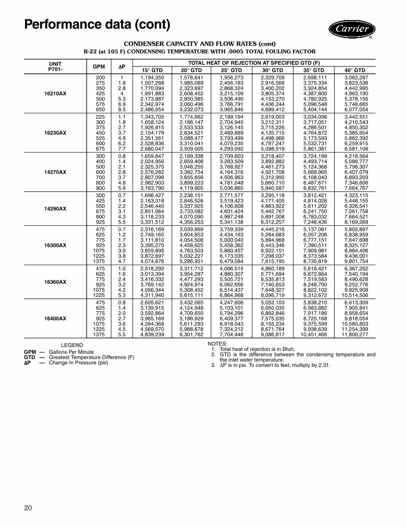
CONDENSER CAPACITY AND FLOW RATES (cont)R-22 (at 105 F) CONDENSING TEMPERATURE WITH .0005 TOTAL FOULING FACTOR
LEGEND NOTES:1. Total heat of rejection is in Btuh.2. GTD is the difference between the condensing temperature and
the inlet water temperature.3. ∆P is in psi. To convert to feet, multiply by 2.31.
UNITP701- GPM ∆∆∆∆P
TOTAL HEAT OF REJECTION AT SPECIFIED GTD (F)15° GTD 20° GTD 25° GTD 30° GTD 35° GTD 40° GTD
16210AX
200 1 1,194,350 1,578,641 1,956,273 2,329,709 2,698,111 3,062,287275 1.8 1,507,268 1,985,089 2,456,183 2,916,566 3,375,334 3,823,536350 2.8 1,770,094 2,323,697 2,868,324 3,400,202 3,924,854 4,442,995425 4 1,991,883 2,608,452 3,215,109 3,805,374 4,387,800 4,963,190500 5.3 2,173,887 2,850,585 3,506,490 4,153,270 4,780,925 5,378,156575 6.9 2,342,974 3,060,496 3,766,791 4,436,244 5,096,548 5,748,665650 8.5 2,486,054 3,232,073 3,965,846 4,689,412 5,404,144 6,077,054
16230AX
225 1.1 1,343,705 1,774,662 2,199,194 2,619,003 3,034,096 3,442,551300 1.8 1,658,124 2,186,147 2,704,940 3,212,311 3,717,051 4,210,543375 2.7 1,926,815 2,533,533 3,126,145 3,715,226 4,286,501 4,850,302450 3.7 2,154,179 2,834,521 3,489,889 4,135,715 4,764,872 5,385,954525 4.9 2,351,561 3,088,477 3,793,499 4,498,966 5,173,593 5,862,392600 6.2 2,528,836 3,310,041 4,079,235 4,797,247 5,532,731 6,259,915675 7.7 2,680,047 3,509,005 4,293,092 5,098,519 5,861,381 6,581,106
14270AX
300 0.8 1,659,847 2,189,338 2,709,603 3,218,407 3,724,199 4,218,564400 1.4 2,024,956 2,659,408 3,283,509 3,892,882 4,493,714 5,086,777500 2.1 2,325,370 3,048,255 3,768,927 4,461,273 5,124,368 5,798,307600 2.8 2,576,282 3,382,754 4,164,316 4,921,708 5,668,965 6,407,079700 3.7 2,807,096 3,655,656 4,506,963 5,312,992 6,108,043 6,893,203800 4.8 2,982,903 3,899,223 4,781,048 5,660,710 6,487,671 7,346,606900 5.9 3,163,790 4,119,905 5,036,865 5,940,587 6,832,761 7,664,767
14290AX
300 0.7 1,696,427 2,238,151 2,771,577 3,295,118 3,812,421 4,323,115425 1.4 2,163,318 2,846,526 3,519,423 4,171,405 4,814,028 5,448,155550 2.2 2,546,440 3,337,925 4,106,608 4,863,922 5,611,202 6,326,541675 3.1 2,851,064 3,733,082 4,601,424 5,442,767 6,241,750 7,061,758800 4.3 3,118,233 4,070,090 4,987,248 5,891,008 6,783,032 7,664,521925 5.5 3,331,512 4,356,253 5,341,138 6,312,257 7,246,436 8,169,269
16300AX
475 0.7 2,316,169 3,039,869 3,759,339 4,445,216 5,137,081 5,802,897625 1.2 2,749,165 3,604,853 4,434,163 5,264,683 6,057,206 6,838,959775 1.7 3,111,810 4,054,506 5,000,040 5,894,968 6,777,151 7,647,698925 2.3 3,395,270 4,458,625 5,458,362 6,443,346 7,390,511 8,325,127
1075 3.0 3,659,895 4,783,503 5,860,457 6,922,151 7,909,981 8,884,4061225 3.8 3,872,697 5,032,227 6,173,035 7,298,037 8,373,584 9,436,0011375 4.7 4,074,876 5,286,951 6,479,584 7,615,195 8,735,819 9,801,754
16360AX
475 1.0 2,518,292 3,311,712 4,096,515 4,860,189 5,618,421 6,367,262625 1.6 3,013,394 3,954,287 4,880,307 5,771,694 6,672,864 7,540,194775 2.4 3,416,332 4,477,293 5,505,721 6,535,813 7,519,583 8,490,628925 3.2 3,769,142 4,924,974 6,062,656 7,140,653 8,248,700 9,252,776
1075 4.2 4,056,344 5,308,452 6,514,437 7,648,327 8,822,102 9,925,9081225 5.3 4,311,940 5,615,111 6,864,968 8,096,719 9,312,672 10,514,506
16400AX
475 0.8 2,605,621 3,432,065 4,247,606 5,052,103 5,838,210 6,613,309625 1.4 3,139,915 4,124,948 5,103,101 6,050,035 6,983,882 7,905,841775 2.0 3,592,864 4,709,650 5,794,296 6,862,846 7,917,186 8,958,654925 2.7 3,965,169 5,186,929 6,409,377 7,575,035 8,725,168 9,818,054
1075 3.6 4,284,368 5,611,293 6,918,043 8,155,234 9,375,599 10,580,8031225 4.5 4,569,570 5,988,678 7,324,212 8,671,764 9,938,639 11,254,3991375 5.5 4,839,239 6,301,762 7,704,446 9,086,817 10,451,466 11,800,277
GPM — Gallons Per MinuteGTD — Greatest Temperature Difference (F)∆∆∆∆P — Change In Pressure (psi)
Performance data (cont)

21
CONDENSER CAPACITY AND FLOW RATES (cont)
R-134a (at 105 F) CONDENSING TEMPERATURE WITH .0005 TOTAL FOULING FACTOR
LEGEND NOTES:1. Total heat of rejection is in Btuh.2. GTD is the difference between the condensing temperature and
the inlet water temperature.3. ∆P is in psi. To convert to feet, multiply by 2.31.
UNITP701- GPM
TOTAL HEAT OF REJECTION AT SPECIFIED GTD (F)15° GTD 40° GTD
∆∆∆∆P THR ∆∆∆∆P THR
0605CX 4 0.43 25,765 0.44 66,79622 9.69 80,103 10.06 194,621
0607CX 8 1.08 46,790 1.12 119,45326 9.55 96,365 9.90 234,015
0610CX 10 0.69 62,074 0.71 159,84040 8.57 151,198 8.93 369,084
0615CX 15 1.50 96,870 1.56 251,11842 9.64 197,657 10.04 490,954
0620CX 15 1.07 100,679 1.11 262,18945 7.88 226,118 8.18 565,547
0625AX 25 0.65 142,136 0.68 361,78185 5.83 294,664 6.12 717,671
0630AX 30 0.71 169,332 0.74 430,97490 5.16 328,979 5.41 804,474
0840AX 40 0.61 229,741 0.64 585,906140 5.83 487,215 6.10 1,186,682
0850AX 50 1.04 294,477 1.08 752,237150 7.41 576,477 7.77 1,414,060
1065AX 100 1.55 491,308 1.62 1,231,276220 6.44 748,299 6.75 1,811,718
1075AX 100 1.75 543,235 1.83 1,371,900220 7.21 857,022 7.56 2,089,682
1290AX 125 1.45 640,243 1.51 1,610,509250 5.17 949,116 5.38 2,331,313
12110AX 125 1.62 702,533 1.68 1,781,996250 5.71 1,081,660 5.95 2,670,390
12140AX 200 0.57 989,938 0.60 2,484,282575 3.61 1,746,399 3.84 4,222,703
14140AX 150 0.86 829,800 0.89 2,106,140450 6.32 1,583,375 6.60 3,828,377
12150AX 225 0.61 1,102,892 0.64 2,759,028675 4.20 1,966,220 4.46 4,725,153
14165AX 100 0.47 648,134 0.49 1,684,102475 7.74 1,852,532 8.09 4,517,159
12200AX 175 0.47 1,029,404 0.49 2,632,546675 4.97 2,340,751 5.27 5,700,528
16200AX 175 0.58 1,017,399 0.61 2,597,916675 6.71 2,295,546 7.02 5,557,759
14210AX 300 0.62 1,500,798 0.65 3,767,346900 4.42 2,723,529 4.65 6,531,613
16210AX 200 1.00 1,184,433 1.04 3,029,886650 8.25 2,421,220 8.66 5,912,984
16230AX 225 1.04 1,331,505 1.08 3,406,100675 7.48 2,629,070 7.83 6,410,453
14270AX 300 0.81 1,644,295 0.85 4,168,315900 5.68 3,074,944 6.00 7,495,165
14290AX 300 0.73 1,681,478 0.76 4,269,982925 5.37 3,264,221 5.66 7,943,303
16300AX 475 0.69 2,288,601 0.73 5,705,5961375 4.53 3,961,437 4.80 9,566,629
16360AX 475 0.97 2,490,601 1.03 6,270,3141225 5.13 4,191,020 5.45 10,215,657
16400AX 475 0.82 2,579,947 0.86 6,522,2301375 5.33 4,703,510 5.64 11,464,852
GPM — Gallons Per MinuteGTD — Greatest Temperature Difference (F)THR — Total Heat of Rejection∆∆∆∆P — Change In Pressure (psi)

22
CONDENSER CAPACITY AND FLOW RATES (cont)
R-507/404A (at 105 F) CONDENSING TEMPERATURE WITH .0005 TOTAL FOULING FACTOR
LEGEND NOTES:1. Total heat of rejection is in Btuh.2. GTD is the difference between the condensing temperature and
the inlet water temperature.3. ∆P is in psi. To convert to feet, multiply by 2.31.
UNITP701- GPM
TOTAL HEAT OF REJECTION AT SPECIFIED GTD (F)15° GTD 40° GTD
∆∆∆∆P THR ∆∆∆∆P THR
0605CX 4 0.43 25,582 0.44 66,02122 9.69 76,649 10.07 186,012
0607CX 8 1.08 46,132 1.12 117,29526 9.56 92,293 9.91 223,811
0610CX 10 0.69 61,395 0.71 157,44040 8.57 145,885 8.93 353,223
0615CX 15 1.50 96,015 1.56 247,45142 9.64 191,905 10.05 471,557
0620CX 15 1.07 99,591 1.11 258,74045 7.88 220,172 8.19 547,035
0625AX 25 0.65 140,108 0.68 355,01885 5.83 283,698 6.13 680,343
0630AX 30 0.71 166,854 0.74 422,29690 5.17 317,371 5.41 764,927
0840AX 40 0.61 226,617 0.64 575,438140 5.83 469,123 6.12 1,133,013
0850AX 50 1.04 290,154 1.08 737,603150 7.41 556,359 7.78 1,346,139
1065AX 100 1.55 481,415 1.62 1,195,454220 6.44 719,947 6.75 1,727,631
1075AX 100 1.75 532,609 1.83 1,339,365220 7.21 827,576 7.57 2,001,385
1290AX 125 1.45 626,889 1.51 1,563,267250 5.17 916,892 5.39 2,235,009
12110AX 125 1.62 690,314 1.69 1,742,825250 5.71 1,048,796 5.96 2,558,547
12140AX 200 0.57 969,692 0.60 2,419,279575 3.61 1,675,473 3.84 4,013,472
14140AX 150 0.86 816,842 0.89 2,060,332450 6.32 1,513,513 6.61 3,655,576
12150AX 225 0.61 1,083,086 0.64 2,693,371675 4.20 1,883,280 4.46 4,481,024
14165AX 100 0.47 643,291 0.49 1,663,120475 7.74 1,788,919 8.10 4,326,399
12200AX 175 0.47 1,016,231 0.49 2,588,503675 4.97 2,253,177 5.28 5,402,854
16200AX 175 0.58 1,004,120 0.61 2,553,079675 6.71 2,208,564 7.02 5,299,788
14210AX 300 0.62 1,471,001 0.65 3,670,893900 4.42 2,612,665 4.65 6,258,033
16210AX 200 1.00 1,168,653 1.04 2,974,120650 8.25 2,333,933 8.67 5,653,432
16230AX 225 1.04 1,313,736 1.08 3,343,356675 7.48 2,530,572 7.84 6,139,566
14270AX 300 0.81 1,616,728 0.85 4,073,584900 5.69 2,958,091 6.01 7,149,523
14290AX 300 0.73 1,655,375 0.76 4,184,727925 5.37 3,144,178 5.67 7,586,650
16300AX 475 0.69 2,238,728 0.73 5,565,0501375 4.53 3,792,706 4.80 9,070,571
16360AX 475 0.98 2,441,137 1.03 6,123,2631225 5.14 4,031,866 5.45 9,774,892
16400AX 475 0.82 2,534,088 0.86 6,380,5181375 5.33 4,524,881 5.65 10,936,480
GPM — Gallons Per MinuteGTD — Greatest Temperature Difference (F)THR — Total Heat of Rejection∆∆∆∆P — Change In Pressure (psi)
Performance data (cont)

23
STANDARD RATINGS FOR COMPRESSORS
STANDARD RATING CONDITIONS
RATING BASIS AND CAPACITY MULTIPLIERS
COMPR
REFRIGERANTR-134a R-22 R-507/404A
Cap.(tons) Bhp THR
(tons)Cap.
(tons) Bhp THR(tons)
Cap.(tons) Bhp THR
(tons)5F20 2.9 5.2 4.0 8.3 10.9 10.4 2.3 5.9 3.65F30 4.4 7.8 6.1 12.6 16.2 15.7 3.5 8.8 5.45F40 5.9 10.3 8.1 16.7 21.6 20.8 4.7 11.6 7.25F60 8.8 15.4 12.1 25.1 32.2 31.3 7.1 17.4 10.85H40 13.8 23.4 18.8 39.9 49.0 49.4 11.4 26.4 17.05H46 17.1 32.3 23.9 49.1 63.7 61.4 14.1 34.3 21.45H60 20.7 36.9 28.6 59.6 73.4 73.7 17.1 39.3 25.45H66 25.8 48.1 36.0 73.9 95.5 92.4 21.3 51.2 32.25H80 27.6 48.9 38.0 79.4 97.5 98.2 22.8 52.1 33.95H86 34.3 63.7 47.8 98.6 126.8 123.0 28.4 68.0 42.85H120 41.5 73.0 57.0 119.2 145.9 147.4 34.3 77.8 50.85H126 51.5 92.1 71.1 147.9 189.7 184.5 42.3 101.2 64.0
REFRIGERANT SST SDT RGT SC RPMR-22 45 130 65 15 1750R-134a 20 120 65 15 1750R-507/404A –10 105 65 5 1750
SAT. SUCTTEMP
(F)
RATED SUCTGAS TEMP
(F)
CAPACITY MULTIPLIERS R-507/404 R-134aActual Suction Gas Temp to Compr (F)
–40 –20 0 10 20 30 40 50 60 65–40 65 0.790 0.830 0.870 0.890 0.910 0.930 0.950 0.970 0.990 1.000–20 65 — 0.830 0.870 0.890 0.910 0.930 0.950 0.970 0.990 1.000
0 65 — — 0.870 0.890 0.910 0.930 0.950 0.970 0.990 1.000
10 65— — — 0.890 0.910 0.930 0.950 0.970 0.990 1.000— — — 0.950 0.959 0.968 0.977 0.986 0.995 1.000
20 65— — — — 0.910 0.930 0.950 0.970 0.990 1.000— — — — 0.960 0.969 0.978 0.987 0.996 1.000
30 65 — — — — — 0.970 0.979 0.987 0.996 1.00040 65 — — — — — — 0.987 0.992 0.997 1.000
LEGEND
Bhp — Brake HorsepowerCap. — CapacityRGT — Return Gas Temp to
Compr (F)SC — Liquid Subcooling (F)
SDT — Saturated DischargeTemp (F)
SST — Saturated SuctionTemp (F)
THR — Total Heat Rejection(tons)
NOTE: The refrigerant ratings closelycorrespond to standard air conditioningand refrigeration conditions in whichthese compressors are typically applied.

24
5F,H RATING LIMITS
LEGEND
MULTIPLYING FACTORS FOROTHER THAN 1750 RPM
LEGEND
CONDENSING UNIT MAXIMUM LIQUID LIFT
LEGEND
*Maximum allowable vertical distance from condenser to evaporatorsections (with evaporator located above condenser. Location of com-pressor is irrelevant, since it contacts gases only at suction anddischarge).
CAPACITY CONTROL REDUCTION STEPS
*5F20 and 5F30 compressors available with or without one cylinder for unloading. Two controlled cylinders (to 331/3%)available on request for 5F30 only.
REFRIGERANTSST SDT
Minimum Maximum Minimum MaximumR-134a 0 50 80 145R-22 –40 50 80 135R-507/404A –60 50 80 120
SDT — Saturated Discharge Temp (F)SST — Saturated Suction Temp (F)
RPM 1450 1160CAPACITY 0.835 0.674BHP 0.798 0.602
Bhp — Brake Horsepower
TEMP DIFF (F)SDT — ENT WATER TEMP
HEIGHT (ft)*R-134a R-22, 507/404A
15 30 5220 37 6425 43 7530 49 8535 53 9340 57 99
45 58 10350 61 10755 62 110
SDT — Saturated Discharge Temperature (F)
COMPRSIZE
CONTROLCYL
CAP. STEPS (% Full Load Cap.)100 871/2 831/3 75 662/3 621/2 50 371/2 331/3 25
% Full Load Bhp100 90 86 80 74 71 60 50 45 38
Number of Active Cylinders5F20* 1 2 — — — — — 1 — — —5F30* 1 3 — — — 2 — — — — —
5F40, 5H40,46 3 4 — — 3 — — 2 — — 15F60, 5H60,66 4 6 — 5 — 4 — 3 — 2 —
5H80, 86 6 8 7 — — — 5 — 3 — 25H120,126 8 12 — 10 — 8 — 6 — 4 —
Performance data (cont)
25
Typical piping and wiring
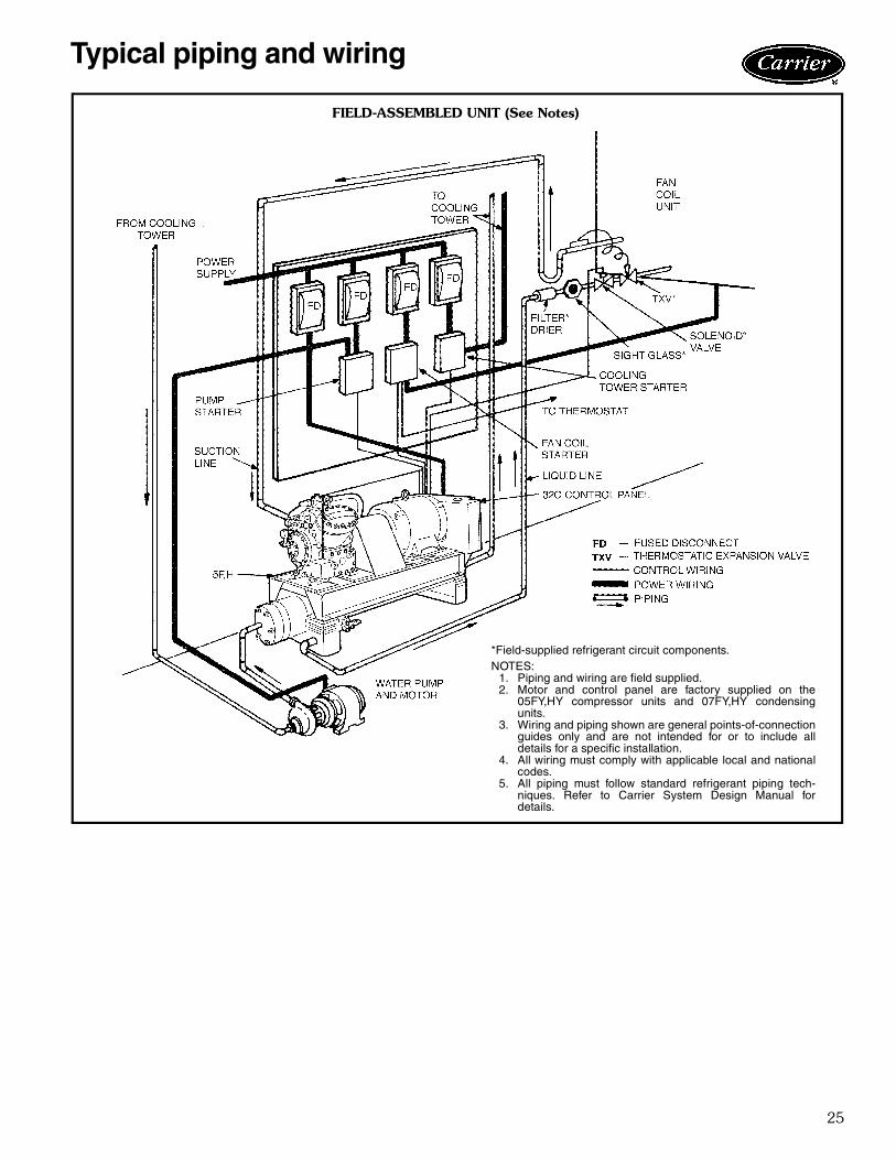
FIELD-ASSEMBLED UNIT (See Notes)
*Field-supplied refrigerant circuit components.NOTES:
1. Piping and wiring are field supplied.2. Motor and control panel are factory supplied on the
05FY,HY compressor units and 07FY,HY condensingunits.
3. Wiring and piping shown are general points-of-connectionguides only and are not intended for or to include alldetails for a specific installation.
4. All wiring must comply with applicable local and nationalcodes.
5. All piping must follow standard refrigerant piping tech-niques. Refer to Carrier System Design Manual fordetails.

26
05FY,HY Open-Direct-Drive andOpen-Belt-Drive ReciprocatingCompressor UnitHVAC Guide SpecificationsSize Range: 5 to 150 TonsCarrier Part Numbers: 05FY,HYPart 1 — General1.01 SYSTEM DESCRIPTION
Compressor unit utilizing direct driven or belt drivenreciprocating type refrigerant compressor.
1.02 QUALITY ASSURANCEA. Unit performance shall be rated according to ARI 520
latest edition, comply with ANSI/ASHRAE 15 latestrevision Safety Code, NEC, and ASME Code.
B. Compressors will be factory run tested to ensureproper performance.
C. Motor and control panel shall be UL listed andNEMA approved.
1.03 DELIVERY, STORAGE AND HANDLINGUnit will be stored and handled according to manu-facturer’s instructions.
Part 2 — Products2.01 EQUIPMENT
A. General:Factory assembled single piece, refrigerant compres-sor unit. Contained within the package shall be anopen-drive reciprocating compressor, motor anddrive package, control package, structural steelbase, wiring, piping, controls, and special featuresrequired prior to field start-up.
B. Compressors:Reciprocating open-drive type only, with shutoffvalves, automatically reversible positive displace-ment oil pump, oil charge, crankcase heater withrelay (standard on 05FY040 and above), and suctionpressure actuated cylinder unloaders.
C. Motor and Drive Package:1. Motor shall be NEMA T-frame only with operat-
ing speed of 1750 rpm.2. Open-Direct-Drive Package shall include motor-
to-compressor coupling and guard, shims andfastening set.Open-Belt-Drive Package shall include beltguard, motor pulley and belts, fastening set, andcompressor flywheel.
D. Controls and Safeties:1. Included in the control panel are power and
control terminal blocks, contactors, controlrelays, on/off switch, pressure gages for oil, dis-charge, and suction pressure. Unit designed tostart with controlled cylinders unloaded.Factory-assembled control box to be tested andmounted on structural base. Controls capable ofinterlocking with evaporator, condenser, orcooling tower fans.
2. Safeties in the control box include high, low,and oil pressure switches, timer to prevent com-pressor short cycling, overload relays or circuitbreakers, and control circuit fuse.
E. Electrical Requirements:All control and power wiring between control boxand compressor shall be factory assembled.
F. Special Features:Certain standard features are removed and replacedby those features designated by *. Consult your localCarrier sales office for amending specifications.
1. Water-Cooled Condenser:Shell and tube with integral finned copper tubesfor field installation. Shall be factory tested tocomply with ASME Code for unfired pressurevessels, ARI Standard 450 for condensers, andANSI/ASHRAE 15 Safety Code. Equippedwith pressure relief, liquid line shutoff, and con-nection for water regulating valve.
2. Discharge Muffler:Discharge line muffler for noise reduction.
3. Vibration Isolators:To prevent transmission of vibration to building.
4. Water-Cooled Oil Cooler:Water-cooled oil cooler to reduce oil tempera-ture during operation.
* 5. Water-Cooled Cylinder Heads:Used to reduce unit operating temperature.
* 6. Partial-Flow Oil Filter:Controls the amount of contaminants withinthe operating oil charge. Partial flow type forsafety.
Guide specifications — 05FY,HY

27
07FY,HY Open-Direct-Drive andOpen-Belt-Drive ReciprocatingWater-Cooled Condensing UnitHVAC Guide SpecificationsSize Range: 5 to 150 TonsCarrier Part Numbers: 07FY,HYPart 1 — General1.01 SYSTEM DESCRIPTION
Condensing unit utilizing direct drive or belt drivenreciprocating type refrigerant compressor andwater-cooled condenser.
1.02 QUALITY ASSURANCEA. Unit performance shall be rated in accordance to ARI
520 latest edition, comply with ANSI/ASHRAE 15latest revision Safety Code, NEC, and ASME Code.
B. Compressors will be factory run tested to ensureproper performance.
C. Motor and control panel shall be UL listed andNEMA approved.
1.03 DELIVERY, STORAGE AND HANDLINGUnit will be stored and handled according to manu-facturer’s instructions.
Part 2 — Products2.01 EQUIPMENT
A. General:Factory assembled single piece, refrigerant compres-sor unit. Contained within the package shall be anopen-drive reciprocating compressor, motor anddrive package, control package, structural steelbase, wiring, piping, controls and special featuresrequired prior to field start-up.
B. Compressors:Reciprocating open-drive type only, with shutoffvalves, automatically reversible positive displacementoil pump, oil charge, crankcase heater with relay, andsuction pressure actuated cylinder unloaders.
C. Motor and Drive Package:1. Motor shall be NEMA T-frame only with operat-
ing speed of 1750 rpm.2. Open-Direct-Drive Package shall include motor-
to-compressor coupling and guard, shims, andfastening set.Open-Belt-Drive Package shall include beltguard, motor pulley and belts, fastening set, andcompressor flywheel.
D. Condenser:Shell and tube with integral finned copper tubes.Shall be factory tested to comply with ASME Codefor unfired pressure vessels, ARI Standard 450 forcondensers, and ANSI/ASHRAE 15 Safety Code.Equipped with pressure relief, liquid line shutoff, andconnection for water regulating valve.
E. Controls and Safeties:1. Included in the control panel are power and
control terminal blocks, contactors, controlrelays, on/off switch, pressure gages for oil, dis-charge, and suction pressure. Unit designed tostart with controlled cylinders unloaded.Factory-assembled control box to be tested andmounted on structural base. Controls capable ofinterlocking with evaporator or cooling towerfans.
2. Safeties in the control box include high, low,and oil pressure switches, timer to prevent com-pressor short cycling, overload relays or circuitbreakers, and control circuit fuse.
F. Electrical Requirements:All control and power wiring between control boxand compressor shall be factory assembled.
G. Special Features:Certain standard features are removed and replacedby those features designated by *. Consult your localCarrier sales office for amending specifications.
1. Vibration Isolators:To prevent transmission of vibration to building.
2. Water-Cooled Oil Cooler:Water-cooled oil cooler to reduce oil tempera-ture during operation.
* 3. Water-Cooled Cylinder Heads:Used to reduce unit operating temperature.
* 4. Partial-Flow Oil Filter:Controls the amount of contaminants withinthe operating oil charge. Partial flow type forsafety.
5. Discharge Muffler:Used for noise reduction. Standard on the07HY040 and larger.
Guide specifications — 07FY,HY

Manufacturer reserves the right to discontinue, or change at any time, specifications or designs without notice and without incurring obligations.New Pg 28 Catalog No. 520-522 Printed in U.S.A. PC 802 Form 5F,H-3PD
Replaces: 5F,H-2PDBook 2 2 4 4Tab 1b 2a 2b 3a
Carrier Corporation • Syracuse, New York 13221 7-02
Book 3Tab DE1