product 62aq energy$recycler data - …dms.hvacpartners.com/docs/1005/public/0f/62aq-1pd.pdf ·...
TRANSCRIPT

Copyright 1999 Carrier Corporation Form 62AQ-1PD
Carrier’s 62AQ Energy$Recycler units are rooftop accessories thatrecover energy from building exhaust air and pre-condition ventilation air. These units are designed to satisfy the new higher ventilation require-ments and other building codes while minimizing the cost of energy.Advantages include:• designing to ASHRAE (American
Society of Heating, Refrigeration, and Air Conditioning Engineers) Standard 62
• UL and UL, Canada listed• a variety of sizes to meet most
application requirements• dehumidification
Features/BenefitsOne-piece unit provides efficiency, cost savings, dependable performance and easy maintenance. Units are ideal for hotels, dormitories, restaurants, hospitals, retail establishments, theaters, schools, and office buildings.Better air quality is provided by introduction of fresh outdoor air to meet ASHRAE 62 requirements.Reduced energy costs compared to heating and cooling systems without the Energy$Recycler unit.Improves indoor air quality by allowing increased ventilation air to meet ASHRAE 62 requirements.Pre-treats the outside air before it enters the rooftop. Ventilation air load handled by Energy$Recycler unit allows use of smaller rooftop units in most applications.
62AQ Energy$RecyclerEnergy Recovery
AccessoryFor 3 to 12.5 Ton Rooftops
600 and 1000 Nominal Cfm
ProductData
62AQ ENERGY$RECYCLER

2
Recovers energy from exhaust air by utilizing building exhaust for con-denser air in cooling mode or evapora-tor load in heating for efficient operation and energy savings when compared to untreated outside air.Easy to install and service, designed to attach directly to rooftop unit with accessory mounting kit. No additional curb or supports required. Single panel service access for exhaust air blower and major refrigerant circuit components. Maintenance-friendly units have rigid, foil faced, cleanable insulation and sloped, noncorrosive drain pans to meet ASHRAE 62P indoor airquality standards. Supply and exhaust air coils protected by 2-in. disposable filters to minimize need for frequentcoil cleaning. Tool-less filter accessprovided.Cabinets are constructed of heavy duty, phosphate, zinc-coated pre-painted steel capable of withstanding 500 hours in salt spray.
Direct-drive multi-speed, PSC (permanent split capacitor) blower motors and adjustable air dampers provided for precise adjust-ment of supply and exhaust air vol-umes to meet customer requirements. PSC motors used to reduce energy consumption.Motor operated, spring return supply air damper and gravity operated barometric relief damper with adjustable stops provided to allow fine tuning of supply and exhaust airflows and positive shutoff in the event of power failure.Energy$Recycler — the IAQ solu-tion for today’s “tight” buildings.Indoor-air quality (IAQ) generally refers to the level of pollutants inside a build-ing. These pollutants include cigarette smoke, carbon dioxide exhaled by occupants, radon gas, car exhaust, paint fumes, and odors.
Concern over increased indoor air pollutants has been spurred by several issues: 1) changes in new building con-struction methods and retrofit of older
buildings have reduced air infiltration rates; 2) Synthetic materials release air-borne particles, odors, and chemicals; and 3) HVAC (heating, ventilation, and air conditioning) systems that bring in minimal fresh air.
In 1989, IAQ concerns caused ASHRAE to recommend increased ventilation for all public buildings. Sim-ply introducing fresh air into a building, however, is not always practical or costeffective. Additional ventilation can overload HVAC systems and increase energy costs.
Carrier’s 62AQ Energy$Recycler unit solves this dilemma by providing increased fresh air while keeping increased costs to a minimum. In addi-tion, the Energy$Recycler helps reducehumidity levels, which helps to prevent deterioration of building materials and retards the growth of mold and mildew.
The 62AQ Energy$Recycler unit provides the best solution to retaining the energy-conserving benefits of today’s tighter building construction while improving indoor-air quality.
Table of contentsPage
Features/Benefits . . . . . . . . . . . . . . . . . . . . . . . . . . . . . . . . . . . . . 1,2Model Number Nomenclature . . . . . . . . . . . . . . . . . . . . . . . . . . . . . . 3Capacities. . . . . . . . . . . . . . . . . . . . . . . . . . . . . . . . . . . . . . . . . . . . 3Physical Data . . . . . . . . . . . . . . . . . . . . . . . . . . . . . . . . . . . . . . . . . 4Field-Installed Accessories. . . . . . . . . . . . . . . . . . . . . . . . . . . . . . . . . 5Base Unit Dimensions . . . . . . . . . . . . . . . . . . . . . . . . . . . . . . . . . . . 6Selection Procedure. . . . . . . . . . . . . . . . . . . . . . . . . . . . . . . . . . . . 7-9Performance Data . . . . . . . . . . . . . . . . . . . . . . . . . . . . . . . . . . . 10-22Electrical Data . . . . . . . . . . . . . . . . . . . . . . . . . . . . . . . . . . . . . . . . 22Typical Installation. . . . . . . . . . . . . . . . . . . . . . . . . . . . . . . . . . . . . 23Typical Wiring Schematic . . . . . . . . . . . . . . . . . . . . . . . . . . . . . . . . 24Controls . . . . . . . . . . . . . . . . . . . . . . . . . . . . . . . . . . . . . . . . . . 25-27Application Data . . . . . . . . . . . . . . . . . . . . . . . . . . . . . . . . . . . . 28,29Guide Specifications . . . . . . . . . . . . . . . . . . . . . . . . . . . . . . . . . 30,31
3
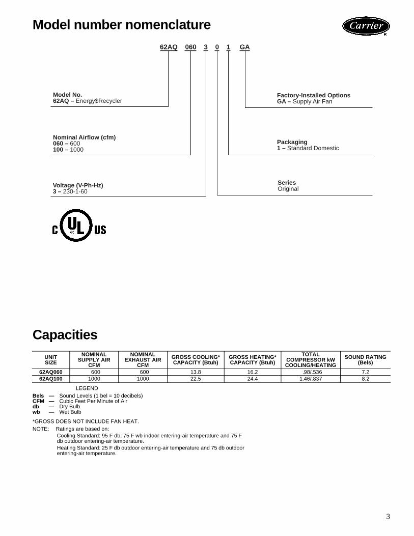
Capacities
LEGEND
*GROSS DOES NOT INCLUDE FAN HEAT.NOTE: Ratings are based on:
Cooling Standard: 95 F db, 75 F wb indoor entering-air temperature and 75 Fdb outdoor entering-air temperature.Heating Standard: 25 F db outdoor entering-air temperature and 75 db outdoorentering-air temperature.
UNITSIZE
NOMINALSUPPLY AIR
CFM
NOMINALEXHAUST AIR
CFM
GROSS COOLING*CAPACITY (Btuh)
GROSS HEATING*CAPACITY (Btuh)
TOTALCOMPRESSOR kWCOOLING/HEATING
SOUND RATING(Bels)
62AQ060 600 600 13.8 16.2 .98/.536 7.262AQ100 1000 1000 22.5 24.4 1.46/.837 8.2
Bels — Sound Levels (1 bel = 10 decibels)CFM — Cubic Feet Per Minute of Airdb — Dry Bulbwb — Wet Bulb
Model number nomenclature
62AQ 060 3 0 1 GA
Voltage (V-Ph-Hz)3 – 230-1-60
Factory-Installed OptionsGA – Supply Air Fan
Packaging1 – Standard Domestic
SeriesOriginal
Model No.62AQ – Energy$Recycler
Nominal Airflow (cfm)060 – 600100 – 1000

4
LEGENDTXV — Thermostatic Expansion Valve
UNIT 62AQ
060 100OPERATING WEIGHT (lb) 225 240Accessory Mounting Kit (lb) 30 30SHIPPING WEIGHT (lb) 245 260COMPRESSOR Rotary
Quantity 1 1Oil (cc) 550 550Suction Line Diameter (in.) 1/2 1/2Discharge Line Diameter (in.) 3/8 3/8Liquid Line Diameter (in.) 3/8 3/8
REGRIGERANT TYPE R-22 Operating Charge (lb) 2 3
CONDENSER COIL (SUPPLY COIL) High-Efficiency Enhanced Copper Tubes, Lanced Aluminum FinsTXV and Acutrol™ Feed Device
Number of Circuits 2 3Rows...Fins/in. 2...15 2...15Total Face Area (sq ft) 1.4 2
EVAPORATOR FAN (EXHAUST AND OPTIONAL SUPPLY FAN) Centrifugal TypeSize (Diameter...Width) 7.12...6 7.12...6Nominal Cfm 600 1000Hp 1/6 1/2Motor Frame 48 48Fan Rpm Range 1125 1735Motor Bearing Type Ball BallMaximum Fan Rpm 1950 1950Nominal Motor Shaft Diameter (in.) 1/2 1/2Type Direct Drive Fan Direct Drive FanNumber of Blades 32 32
EVAPORATOR COIL (EXHAUST COIL) High-Efficiency Enhanced Copper Tubes, Lanced Aluminum FinsTXV and Acutrol Feed Device
Number of Circuits 2 3Rows...fins/in. 2...15 3...15Total Face Area (sq ft) 2 2
HIGH PRESSURE SWITCH (psig)Cutout 428Reset (Auto.) 320
OUTDOOR-AIR INLET SCREEN CleanableQuantity...Size (in.) 1...20x24x1
SUPPLY AND EXHAUST AIR FILTERS ThrowawayQuantity...Size (in.) 1...12x24x1
Physical data

5
Supply-air fan kits are available to upgrade62AQ060301 and 62AQ100301 series units requiringhigher than anticipated supply air volumes.Mounting rail kit is required for attachment of theEnergy$Recycler on 3 to 12.5 ton Carrier units. Kitsinclude telescoping crossrails and extender rails to supportthe Energy$Recycler unit, with several different holes toaccommodate different rooftop unit sizes. The kit includesbase rail extensions, cross members to support the 62AQunit, return air baffle components, and associated hard-ware. No additional roof curb or supports are required tomount the 62AQ to the rooftop unit.Transformer kit provides use of 208/230 v single-phaseEnergy$Recycler unit on 460-3-60 v rooftop units.
Field-installed accessoriesSUPPLY AIR FAN (ACCESSORY)
ROOFTOPUNIT
ACCESSORY MOUNTING RAIL
6
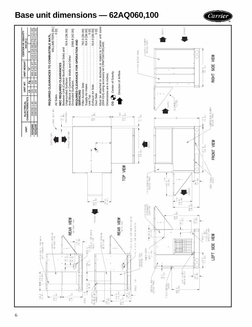
Base unit dimensions — 62AQ060,100U
NIT
ELE
CT
RIC
AL
CH
AR
AC
TE
RIS
TIC
SU
NIT
WT
.U
NIT
HE
IGH
TC
EN
TE
R O
F G
RA
VIT
Ym
m [i
n.]
LbK
g“A
”X
Y62
AQ
060
208/
230-
1-60
225
102
809.
4 [3
1.87
]41
9.0
[16.
50]
279.
4 [1
1.00
]62
AQ
100
208/
230-
1-60
240
109
809.
4 [3
1.87
]41
9.0
[16.
50]
279.
4 [1
1.00
]
RE
QU
IRE
D C
LEA
RA
NC
ES
TO
CO
MB
US
TIB
LE M
AT
L.M
ILLI
ME
TE
RS
[IN
.]A
ll S
ides
. . .
. . .
. . .
. . .
. . .
. . .
. . .
. . .
. . .
. . .
. . .
. . .
. 0
[0]
NE
C R
EQ
UIR
ED
CLE
AR
AN
CE
SB
etw
een
Uni
t (C
ontr
ol B
ox/E
xhau
st S
ide)
and
Ung
roun
ded
Sur
face
s . .
. . .
. . .
. . .
. . .
. . .
. .
914.
0 [3
6.00
]A
nd B
lock
or
Con
cret
e W
alls
and
Oth
erG
roun
ded
Sur
face
s. .
. . .
. . .
. . .
. . .
. . .
. . .
106
6.8
[42.
00]
RE
QU
IRE
D C
LEA
RA
NC
E F
OR
OP
ER
AT
ION
AN
DS
ER
VIC
ING
Filt
er A
cces
s S
ide
. . .
. . .
. . .
. . .
. . .
. . .
. . .
. 76
2.0
[30.
00]
Sup
ply-
Air
Inta
ke. .
. . .
. . .
. . .
. . .
. . .
. . .
. . .
914
.0 [3
6.00
]U
nit T
op. .
. . .
. . .
. . .
. . .
. . .
. . .
. . .
. . .
. . .
. . .
. . .
. .
0 [0
]E
xhau
st A
ir S
ide
. . .
. . .
. . .
. . .
. . .
. . .
. . .
. .
914.
0 [3
6.00
]D
uct S
ide
. . .
. . .
. . .
. . .
. . .
. . .
. . .
. . .
. . .
. . .
. . .
. . .
0 [0
]M
ust
be a
ttach
ed t
o du
ctw
ork
or m
ated
to
Car
rier
unit
size
s(0
04-0
14)
usin
g ac
cess
ory
kit C
RM
TG
KIT
001A
00.
Dim
ensi
ons
are
in in
ches
.
CG
C
ente
r of
Gra
vity
Dire
ctio
n of
Airf
low

7
I Determine cooling and heating loads at designconditions.Given:Required Cooling Capacity (TC) . . . . . .67,000 BtuhSensible Heat Capacity (SHC). . . . . . . .46,000 BtuhRequired Heating Capacity . . . . . . . . . .60,000 BtuhOutdoor Entering-Air Temperature db . . . . . . . .95 FOutdoor Entering-Air Temperature wb. . . . . . . .75 FOutdoor-Air Entering Airflow Cfm . . . . . . 450 CfmOutdoor-Air Winter Design Temperature . . . . . . 0° FIndoor-Air Winter Design Temperature . . . . . . .70 FAir to room including outdoor air . . . . . . 2000 CfmExternal Static Pressure . . . . . Supply — 0.60 in. wg
Return — 0.2 in. wgIndoor-Air Temperature db (room air) . . . . . . . .78 FIndoor-Air Temperature wb (room air) . . . . . . . .65 FIndoor-Air Exhaust Cfm . . . . . . . . . . . . . . 450 CfmElectrical Characteristics (V-Ph-Hz) . . . . . . 230-3-60Vertical discharge unit with Energy$Recyclerrequired.
II Determine fan speed and power requirementsat design conditions.Before entering the Fan Performance tables, calculatethe total static pressure required based on unit com-ponent. From the given and the Accessory/FIOPStatic Pressure of the 50HJQ Product Data book find:External static pressure supply 0.6 in. wgExternal static pressure return 0.2 in. wgAccessory static — None 0.0 in. wgTotal Static 0.8 in. wgEnter the Fan Performance table for vertical dis-charge, from the Fan Performance table of the50HJQ006 at 0.80 in. wg at 2000 cfm the rpm is1226 and bhp is 1.33.NOTE: Convert bhp to Fan Heat and Watts using theformula found in the note following the Indoor-FanMotor Efficiency table from the 50HJQ Product Databook.For this example:Watts = (746 x Bhp)/(motor efficiency)Watts = (746 x 1.33)/(0.74) = 1341 wattsIndoor Fan Heat = watts x 3.413 Btuh/watt
= 1341 x 3.413 = 4577 BtuhIII Select Energy$Recycler based on Outdoor
Entering Cfm.Entering Energy$Recycler see the Cooling Ratings ta-ble in the Capacities section of this book at 450 cfmentering outdoor airflow. Choose Model 62AQ060.Using 450 cfm outdoor supply airflow, 95 F OD DB,and 75 F OD WB find performance of the 62AQ060at these conditions:Energy$Recycler Gross Cooling
Capacity is 13,000 BtuhEnergy$Recycler Gross Sensible
Capacity is 10,090 BtuhCompressor power is 1.06 kWEnergy$Recycler Leaving db is 73.0 FEnergy$Recycler Leaving wb is 66.9 F
IV Using the simplified* method below, calculatethe approximate mixed air temperature for therooftop unit evaporator coil.Using the outdoor-air entering cfm, the room cfm andthe room exhaust airflow with their respective db andwb temperatures, determine the db and wb enteringthe rooftop evaporator coil.a) Estimate the mixed air db to the evaporator coil.
t mix db = ((cfm oa x t oa db) + ((cfm ra – cfm exh)x t ra db)) / (cfm ao + (cfm ra – cfm exh))((450 cfm x 73.0 F) + ((2000 cfm – 450 cfm) x78 F)) / (450 cfm + (2000 cfm – 450 cfm))Mixed air into the rooftop evaporator coil = 76.9 F db
b) Estimate the mixed air wb to the evaporator coil.t mix wb* = ((cfm oa x t oa wb) + ((cfm ra – cfmexh) x t ra wb)) / (cfm oa + (cfm ra – cfm exh))((450 cfm x 66.9F) + ((2000 cfm – 450 cfm) x65 F)) / (450 cfm + (2000 cfm – 450 cfm))Mixed air temperature into the rooftop evaporator= 65.40 F wb*Simplified method of determining wet bulb (wb)temperature of mixture. This approximation isused because the wb lines in the area of the psy-chrometric chart in the area used in the calcula-tion is relatively linear, providing a close approxi-mation. A more accurate solution can be foundusing the E-Cat program.
LEGEND
V Determine the cooling load requirement for therooftop unit.Customer load is 67,000 BtuhLess TC supplied by the
Energy$Recycler –13,000 BtuhRooftop cooling load required is 54,000 Btuh
VI Select the rooftop unit based on mixed airentering conditions and cooling load.Enter cooling capacity table at outdoor entering tem-perature 95 F, mixed air entering evaporator at2000 cfm, 76.9 F db, and 65.4 F wb.The 50HJQ006 will provide a total gross coolingcapacity of 59,420 Btuh and sensible cooling of42,920 Btuh.Since these values were not at 80 F entering db, theywere calculated based on the notes following theCooling Capacity tables.NOTE: Unit ratings are gross capacities and do notinclude the effect of evaporator-fan motor heat. Tocalculate net capacities see Steps VII and VIII.
cfm — cubic feet per minute of airdb — dry bulbexh — Energy$Recycler dischargemix — mixture of outdoor + return airoa — outside air leaving Energy$Recyclerra — return airsa — supply air at coil (sa = oa + ra – exh)t — temperaturewb — wet bulb
Selection procedure (with 50HJQ006 example)

8
VII Select net heating capacity of unit to meetdesign condition requirements.Enter the Instantaneous and Integrated Heating ratingtable (from the 50HJQ Fan Performance Data sec-tion) for the rooftop at 2000 cfm. At 70 F return in-door air and 0° F air entering outdoor coil, the inte-grated heating capacity is 27,100 Btuh. (Select inte-grated heating capacity value since deductions foroutdoor-coil frost and defrosting have already beenmade. No correction is required.)Enter the 62AQ060 Heating rating table at 450 cfm.At 70 F and 0° F find the heating value for theEnergy$Recycler to be 15.2 Btuh. The customer heat requirement is 60,000 Btuh.Integrated Heat Capacity Rooftop 27,100 Btuhadd Rooftop fan heat from Step II 4,577 BtuhEnergy$Recycler Heat Capacity 15,200 Btuhadd Energy$Recycler optional
supply fan heat if supplied 0 BtuhTotal Unit heat with Energy$Recycler 46,877 BtuhDetermine additional electric heat capacity.The required heating capacity is 60,000 Btuh. There-fore, 13,123 Btuh (60,000 – 46,877) additional heatis required.Determine additional electric heat in kW.(13,123/3413 Btuh/kW) = 3.84 kW of heat isrequired.Enter 62AQ060 Heating tables, from page 10 of thisbook, for 50HJQ006 at 208/230, 3 phase. The6.5 kW heater at 240 v most closely satisfies the heat-ing required. To calculate kW at 230 v use the Multi-plication Factors table.6.5 kW x 0.92 = 5.98 kW6.5 kW x 0.92 x 3413 Btuh/kW = 20,410 BtuhTotal unit net heating capacity is 67,287 Btuh(46,877 + 20,410).
VIII Determine net cooling capacity.Cooling capacities are gross capacities anddo not include indoor (evaporator) or optionalEnergy$Recycler supply fan heat.Determine net cooling capacity using the followingformula:Net Capacity = (Gross Capacity Rooftop Unit +Energy$Recycler) – (Indoor [evaporator] fan motor[IFM] Heat + Optional Energy$Recycler Supply FanMotor Heat)Gross Total CoolingRooftop from run 59,420 BtuhEnergy$Recycler 13,000 BtuhTotal 72,420 BtuhLessIFM heat (from Step II) <4,577> BtuhOpt. Energy$Recycler Supply
Fan Motor Heat noneNet Total Capacity 67,843 Btuh
Gross Sensible CoolingRooftop from run 42,920 BtuhEnergy$Recycler 10,090 BtuhTotal 53,010 BtuhLessIFM heat (from Step II) <4,577> BtuhOpt. Energy$Recycler Supply
Fan Motor Heat noneNet Sensible Capacity 48,433 Btuh
IX Determine the operating watts of the rooftopunit and Energy$Recycler unit.Cooling with Energy$Recycler in operation:a) Rooftop unit:
Refer to the 50HJQ Product Data catalog.Using the 50HJQ006 cooling capacitytable and the calculations described inStep VI of this procedure, determinecompressor watts 4,670 wattsIndoor fan motor from Step II** 1,341 wattsOutdoor fan motor from Physical Data table find1/4 hp†Assume OD motor efficiency is 0.75.Watts = (746 x hp)/(motor Eff)
= (746 x 1/4)/(0.75)= 249 watts
†Dual circuit units will have two outdoor fans, dou-ble values.
b) Energy$Recycler:Compressor watts from 62AQ060Cooling Ratings table, page 7 1,060 wattsOptional supply fan fromfan curves none selectedExhaust fan operating watts from 62AQ060 Ex-haust Fan Performance Curve at 230-v, 450 cfm,0.2 in. wg, Static 110 watts.Total watts for the unit in operationat design conditions 7,430 watts
X Electrical data RLA, FLA, LRA, MCA andMOCP.Separate Power Supply:If the 62AQ is wired for separate power see the Elec-trical Data table.Single Power Supply with Unit:The unit is 230 v-3-60 Hz, so from the 50HJQ Prod-uct Data Electrical Data table Without ConvenienceOutlet and with a 6.5 kW heater, find unit electricaldata. For the rooftop unit the data is MCA= 48.4 amps, MOCP = 50 amps, Min Unit Discon-nect Size FLA = 46, and LRA = 183.For this example follow the steps outlined in the Ap-plication Data section (pages 28 and 29) for singlepower supply for all rooftop units except size 014(230-v) and 62AQ on 460-v power supply. For othersize and voltage conditions follow corresponding stepsalso outlined in the Application data section.
Selection procedure (cont)

9
From the Single Power Supply table (Electrical Datapage 22 this book) find 230 v, for 62AQ060300,“X” = 8.1 amps and “Y” = 9.3 amps.Add “X” amps to the MCA and MOCP and add “Y”amps to the minimum disconnect size.
(MOCP calculation is 58.1 round down to 50. 50 isnow less than the MCA therefore round up to 60. 60is the new MOCP.)The wiring to the unit must be suitable for the MCAcalculated above.
The overcurrent protective device for the combinationload is equal to 60, thus a single disconnect may beused for BOTH the MAIN UNIT and the 62AQ pro-vided that the wire supplying the 62AQ is sized for aminimum of 33% of the maximum overcurrent pro-tection device value (i.e., 60 x .33 = 20 Amps). Nofurther subfusing is required.In this example a 60-amp disconnect would be usedfor the combined load of the 50HJQ006 with a6.5 kW heater and the 62AQ060 Energy$Recyclerunit.
MCA MOCP FLA LRA50HJQ 48.4 50 46 18362AQ 8.1 8.1 9.3 31.7Total 56.5 58.1 55.3 214.7

10
62AQ060 HEATING
LEGEND
TEMP (F)AIR ENTERINGEVAPORATOR
SUPPLY AIRENTERING COND
300 CFMEXHAUST AIR
450 CFMEXHAUST AIR
600 CFMEXHAUST AIR
EDB CFM THC CMP LDB THC CMP LDB THC CMP LDB
70
0300 13.9 0.469 37.6 — — — — — —450 14.0 0.409 25.3 15.2 0.426 27.5 — — —600 14.1 0.382 19.0 15.3 0.397 20.7 16.0 0.406 21.7
10300 13.6 0.522 47.7 — — — — — —450 13.9 0.456 35.5 15.0 0.473 37.7 — — —600 14.0 0.424 29.3 15.2 0.440 31.0 15.9 0.449 32.0
25300 13.3 0.621 63.0 — — — — — —450 13.5 0.537 50.7 14.6 0.557 52.8 — — —600 13.6 0.498 44.4 14.7 0.515 46.0 15.4 0.525 47.0
33300 13.1 0.679 71.1 — — — — — —450 13.3 0.587 58.7 14.4 0.608 60.8 — — —600 13.4 0.544 52.4 14.5 0.562 54.0 15.2 0.572 55.0
47300 12.8 0.794 85.1 — — — — — —450 13.0 0.689 72.8 13.9 0.709 74.7 — — —600 13.1 0.638 66.5 14.1 0.656 68.0 14.6 0.663 68.8
70300 12.3 1.020 108.0 — — — — — —450 12.5 0.891 95.9 13.2 0.908 97.4 — — —600 12.5 0.826 89.5 13.4 0.845 90.9 13.9 0.852 91.6
75
0300 14.5 0.482 39.4 — — — — — —450 14.7 0.418 26.5 15.9 0.437 28.8 — — —600 14.7 0.390 19.9 16.0 0.406 21.7 16.8 0.416 22.8
10300 14.3 0.436 49.4 — — — — — —450 14.5 0.465 36.7 15.7 0.485 39.0 — — —600 14.6 0.433 30.2 15.9 0.450 32.0 15.7 0.460 33.0
25300 13.9 0.633 64.6 — — — — — —450 14.1 0.548 51.9 15.3 0.569 54.1 — — —600 14.3 0.507 45.3 15.5 0.525 47.0 16.2 0.536 48.0
33300 13.7 0.693 72.7 — — — — — —450 13.9 0.600 59.9 15.0 0.621 62.1 — — —600 14.1 0.554 53.4 15.2 0.572 55.0 15.9 0.584 56.0
47300 13.4 0.815 86.9 — — — — — —450 13.6 0.701 74.0 14.6 0.723 75.9 — — —600 13.7 0.648 67.4 14.8 0.667 69.0 15.3 0.675 69.8
70300 12.9 1.050 110.0 — — — — — —450 13.0 0.905 97.0 13.8 0.924 98.6 — — —600 13.1 0.839 90.4 14.0 0.858 91.8 14.5 0.866 92.6
CMP — Compressor Power (kW)COND— CondenserEDB — Entering Dry BulbEVAP — EvaporatorLDB — Leaving Dry BulbTHC — Total Heat Capacity (1000 Btuh) Gross
Performance data

11
62AQ100 HEATING
LEGEND
TEMP (F)AIR ENTERINGEVAPORATOR
SUPPLY AIRENTERING COND
600 CFMEXHAUST AIR
800 CFMEXHAUST AIR
1000 CFMEXHAUST AIR
EDB CFM THC CMP LDB THC CMP LDB THC CMP LDB
70
0600 21.9 0.671 29.4 — — — — — —800 22.1 0.613 22.2 23.2 0.633 23.3 — — —
1000 22.2 0.580 17.8 23.3 0.597 18.8 24.1 0.608 19.4
10600 21.8 0.763 39.8 — — — — — —800 21.9 0.693 32.5 23.0 0.712 33.6 — — —
1000 22.0 0.653 28.0 23.1 0.670 28.9 23.8 0.683 29.6
25600 21.2 0.907 54.9 — — — — — —800 21.4 0.831 47.7 22.3 0.846 48.7 — — —
1000 21.5 0.782 43.2 22.6 0.801 44.1 23.3 0.816 44.7
33600 20.8 0.994 62.9 — — — — — —800 21.1 0.911 55.7 22.1 0.935 56.8 — — —
1000 21.2 0.855 51.2 22.2 0.876 52.1 22.9 0.890 52.7
47600 20.3 1.170 76.9 — — — — — —800 20.5 1.070 69.7 21.4 1.100 70.7 — — —
1000 20.5 1.000 65.2 21.5 1.020 66.0 22.1 1.040 66.6
70600 19.4 1.500 99.9 — — — — — —800 19.6 1.380 92.7 20.4 1.410 93.5 — — —
1000 19.7 1.310 88.2 20.5 1.330 89.0 21.0 1.330 89.4
75
0600 23.0 0.693 30.8 — — — — — —800 23.1 0.630 23.2 24.3 0.651 24.4 — — —
1000 23.2 0.596 18.7 24.4 0.613 19.6 25.2 0.626 20.3
10600 22.7 0.780 41.0 — — — — — —800 22.9 0.711 33.5 24.0 0.733 34.7 — — —
1000 23.0 0.670 28.9 24.2 0.688 29.8 24.9 0.701 30.5
25600 22.1 0.932 56.2 — — — — — —800 22.3 0.846 48.6 23.4 0.869 49.8 — — —
1000 22.6 0.801 44.1 23.7 0.823 45.0 24.4 0.837 45.7
33600 21.8 1.020 64.3 — — — — — —800 22.0 0.924 56.6 23.0 0.949 57.7 — — —
1000 22.2 0.876 52.1 23.2 0.898 53.0 23.9 0.913 53.6
47600 21.2 1.19 78.2 — — — — — —800 21.4 1.09 70.7 22.4 1.120 71.8 — — —
1000 21.5 1.02 66.1 22.5 1.050 66.9 23.2 1.060 57.5
70600 20.2 1.53 101.0 — — — — — —800 20.5 1.41 93.7 21.3 1.440 94.6 — — —
1000 20.5 1.32 89.0 21.3 1.350 89.7 22.0 1.370 90.3
CMP — Compressor Power (kW)COND— CondenserEDB — Entering Dry BulbEVAP — EvaporatorLDB — Leaving Dry BulbTHC — Total Heat Capacity (1000 Btuh) Gross

12 Perform
ance data (cont)62AQ060 COOLING RATINGS
LEGEND
SUPPLY AIR ENTERING EVAPORATOR CFM/BFEXHAUST
AIR ENTERINGCONDENSER
300/0.25 450/0.26 600/0.29
Supply Air — EDB (F)/EWB (F)
CFM F 67/62 80/67 125/72 75/74 95/75 80/78 89/80 89/82 67/62 80/67 125/72 75/74 95/75 80/78 89/80 89/82 67/62 80/67 125/72 75/74 95/75 80/78 89/80 89/82
300
75
TC 9.47 10.2 12.7 11.4 11.5 12.2 12.5 12.8 10.0 10.8 13.9 12.1 12.1 12.7 12.9 13.1 10.4 11.2 14.4 12.4 12.4 12.8 13.2 13.3SHC 4.52 6.46 12.7 2.93 7.85 3.03 4.79 4.14 5.08 7.82 13.9 3.01 9.88 3.18 5.57 4.71 5.57 9.06 14.4 3.08 11.6 3.32 6.27 5.17CMP 1.10 1.14 1.29 1.19 1.20 1.24 1.26 1.27 1.13 1.17 1.34 1.23 1.25 1.27 1.28 1.29 1.15 1.19 1.37 1.25 1.27 1.28 1.31 1.32LDB 53.0 59.5 81.3 65.8 69.4 70.4 73.6 75.7 56.5 63.5 93.0 68.7 73.5 73.3 77.0 78.9 58.4 65.6 100.0 70.2 76.0 74.7 78.9 80.7LWB 50.7 55.7 57.8 63.3 64.0 67.5 69.5 71.8 54.3 59.3 62.0 66.8 67.5 71.0 73.1 75.3 56.1 61.1 64.5 68.6 69.3 72.8 74.8 77.0
80
TC 9.26 10.0 12.5 11.2 11.2 11.9 12.2 12.4 9.80 10.6 13.6 11.8 11.8 12.3 12.5 12.7 10.1 10.9 — 12.1 12.1 12.4 12.8 13.0SHC 4.44 6.38 12.5 2.86 7.78 2.96 4.72 4.06 4.99 7.73 13.6 2.93 9.80 3.11 5.48 4.62 5.48 8.97 — 3.01 11.5 3.25 6.17 5.03CMP 1.16 1.20 1.35 1.26 1.27 1.31 1.32 1.34 1.19 1.23 1.41 1.30 1.31 1.33 1.34 1.35 1.21 1.26 — 1.32 1.33 1.34 1.37 1.38LDB 53.3 59.8 82.1 66.0 69.6 70.6 73.8 76.9 59.7 63.6 93.7 68.9 73.7 73.4 77.2 79.1 58.5 65.8 — 70.3 76.3 74.9 79.1 80.9LWB 51.0 55.9 58.1 63.6 64.3 67.8 69.8 72.1 54.5 59.5 62.3 67.0 67.7 71.2 73.3 75.5 56.3 61.3 — 68.7 69.5 73.0 74.9 77.1
450
75
TC — — — — — — — — 10.6 11.4 14.9 12.9 13.0 13.8 14.0 14.2 10.9 11.8 15.5 13.4 13.4 14.0 14.2 14.3SHC — — — — — — — — 5.27 8.01 14.9 3.23 10.1 3.42 5.86 4.97 5.78 9.29 15.5 3.31 12.0 3.57 6.56 5.47CMP — — — — — — — — 0.974 1.00 1.13 1.05 1.06 1.09 1.09 1.10 0.988 1.02 1.17 1.07 1.08 1.09 1.10 1.11LDB — — — — — — — — 56.1 63.0 90.8 68.2 73.0 72.8 76.4 78.3 58.0 65.3 98.3 69.8 75.5 74.3 78.4 80.2LWB — — — — — — — — 53.9 58.8 61.3 66.2 66.9 70.3 72.4 74.7 55.8 60.8 63.8 68.1 68.8 72.3 74.3 76.6
80
TC — — — — — — — — 10.3 11.1 14.6 12.7 12.7 13.5 13.6 13.8 10.7 11.6 15.2 13.0 13.1 13.6 13.8 14.0SHC — — — — — — — — 5.18 7.92 14.6 3.16 10.1 3.34 5.77 4.89 5.69 9.20 15.2 3.24 11.9 3.49 6.47 5.37CMP — — — — — — — — 1.03 1.05 1.19 1.11 1.12 1.14 1.15 1.16 1.04 1.07 1.21 1.13 1.14 1.15 1.16 1.16LDB — — — — — — — — 56.3 63.2 91.6 68.4 73.1 72.9 76.6 78.5 58.2 65.4 98.9 69.9 75.6 74.5 78.6 80.3LWB — — — — — — — — 54.1 59.0 61.5 66.4 67.1 70.6 72.6 74.9 55.9 60.9 64.0 68.2 69.0 72.5 74.5 76.7
600
75
TC — — — — — — — — — — — — — — — — 11.2 12.2 16.1 13.9 13.8 14.6 14.8 15.0SHC — — — — — — — — — — — — — — — — 5.86 9.42 16.1 3.43 12.1 3.70 6.73 5.63CMP — — — — — — — — — — — — — — — — 0.906 0.938 1.05 0.98 0.98 1.00 1.01 1.01LDB — — — — — — — — — — — — — — — — 57.9 65.1 97.3 69.6 75.3 74.1 78.2 79.9LWB — — — — — — — — — — — — — — — — 55.7 60.5 63.5 67.9 68.7 72.0 74.1 76.3
80
TC — — — — — — — — — — — — — — — — 10.9 11.9 15.7 13.6 13.5 14.3 14.5 14.6SHC — — — — — — — — — — — — — — — — 5.77 9.33 15.7 3.36 12.0 3.62 6.63 5.54CMP — — — — — — — — — — — — — — — — 0.955 0.988 1.10 1.03 1.03 1.05 1.06 1.06LDB — — — — — — — — — — — — — — — — 58.0 65.2 97.9 69.7 75.4 74.3 78.3 8.01LWB — — — — — — — — — — — — — — — — 55.8 60.7 63.7 68.0 68.8 72.2 74.2 76.4
BF — Bypass FactorCMP — Compressor Power (kW)EDB — Entering Dry BulbEWB — Entering Wet BulbLDB — Leaving Dry BulbLWB — Leaving Wet BulbSHC — Sensible Heat Capacity (1000 Btuh) GrossTC — Capacity (1000 Btuh) Gross

13
62AQ100 COOLING RATINGS
LEGEND
SUPPLY AIR ENTERING EVAPORATOR CFM/BFEXHAUST
AIR ENTERINGCONDENSER
600/0.3 800/0.32 1000/0.34
Supply Air — EDB (F)/EWB (F)
CFM F 67/62 80/67 125/72 75/74 95/75 80/78 89/80 89/82 67/62 80/67 125/72 75/74 95/75 80/78 89/80 89/82 67/62 80/67 125/72 75/74 95/75 80/78 89/80 89/82
600
75
TC 16.4 17.7 22.8 19.9 19.9 21.0 21.6 22.3 17.0 18.4 24.8 20.5 20.6 21.7 22.3 23.0 17.5 18.8 26.1 20.9 20.9 22.2 22.8 23.5SHC 8.51 12.2 22.8 5.88 15.0 6.13 9.46 8.36 9.21 13.9 24.8 5.98 17.5 6.39 10.6 9.25 9.88 15.5 26.1 6.10 19.6 6.64 11.7 10.1CMP 1.48 1.54 1.79 1.63 1.64 1.68 1.71 1.74 1.51 1.57 1.89 1.65 1.67 1.71 1.74 1.77 1.53 1.59 1.96 1.67 1.69 1.73 1.77 1.80LDB 54.0 60.9 86.2 65.9 70.8 70.4 73.9 75.7 56.4 63.6 93.4 68.0 73.9 72.5 76.4 78.0 57.9 65.4 98.3 69.3 76.1 73.8 77.8 79.4LWB 52.4 57.4 59.5 64.9 65.6 69.1 71.1 73.3 54.7 59.7 62.1 67.2 67.9 71.3 73.3 75.4 56.1 61.1 63.8 68.5 69.3 72.6 74.6 76.7
80
TC 16.0 17.3 22.4 19.3 19.4 20.6 21.1 21.7 16.6 17.9 24.3 20.0 20.1 21.2 21.8 22.4 17.1 18.3 25.6 20.4 20.5 21.6 22.3 22.9SHC 8.35 12.1 22.4 5.69 14.9 5.99 9.32 8.23 9.05 13.7 24.3 5.83 17.3 6.25 10.5 9.11 9.71 15.3 25.6 5.96 19.3 6.50 11.6 9.96CMP 1.57 1.63 1.89 1.70 1.72 1.76 1.80 1.83 1.59 1.66 1.99 1.74 1.76 1.80 1.83 1.86 1.61 1.68 2.06 1.76 1.78 1.82 1.86 1.89LDB 54.2 61.1 86.8 66.2 71.0 70.6 74.2 75.9 56.6 63.8 94.0 68.2 74.1 72.7 76.5 78.1 58.1 65.6 98.9 69.4 76.3 73.9 77.9 79.5LWB 52.7 57.6 59.7 65.2 65.9 69.4 71.3 73.5 54.9 59.9 62.3 67.3 68.1 71.5 73.4 75.6 56.2 61.2 63.9 68.6 69.4 72.8 74.7 76.8
800
75
TC — — — — — — — — 17.6 19.0 25.7 21.3 21.4 22.7 23.3 24.0 18.1 19.4 27.2 21.8 21.9 23.2 23.8 24.6SHC — — — — — — — — 9.43 14.2 25.7 6.23 17.8 6.64 10.9 9.51 10.1 15.7 27.2 6.36 20.0 6.90 12.0 10.4CMP — — — — — — — — 1.39 1.44 1.69 1.51 1.52 1.56 1.58 1.61 1.41 1.45 1.75 1.52 1.54 1.57 1.60 1.63LDB — — — — — — — — 56.2 63.3 92.2 67.8 73.5 72.2 76.0 77.6 57.7 65.2 97.2 69.1 75.6 73.5 77.6 79.1LWB — — — — — — — — 54.5 59.4 61.6 66.8 67.6 71.0 72.9 75.1 55.9 60.9 63.4 68.2 69.0 72.3 74.3 76.4
80
TC — — — — — — — — 17.2 18.5 25.3 20.8 21.0 22.2 22.8 23.5 17.6 18.9 26.7 21.3 21.4 22.6 23.3 24.0SHC — — — — — — — — 9.27 14.0 25.3 6.08 17.6 6.50 10.7 9.38 9.93 15.6 26.7 6.22 19.8 6.76 11.8 10.2CMP — — — — — — — — 1.47 1.51 1.78 1.59 1.61 1.64 1.67 1.69 1.48 1.53 1.84 1.60 1.62 1.65 1.69 1.71LDB — — — — — — — — 56.3 63.6 92.8 67.9 73.7 72.4 76.2 77.8 57.9 65.4 97.7 69.2 75.8 73.7 77.7 79.2LWB — — — — — — — — 54.6 59.6 61.8 67.0 67.7 71.2 73.1 75.2 56.0 61.0 63.5 68.4 69.2 72.5 74.4 76.5
1000
75
TC — — — — — — — — — — — — — — — — 18.3 19.9 27.8 22.4 22.5 23.8 24.5 25.3SHC — — — — — — — — — — — — — — — — 10.2 15.9 27.8 6.52 20.3 7.07 12.1 10.5CMP — — — — — — — — — — — — — — — — 1.33 1.37 1.62 1.44 1.46 1.48 1.51 1.53LDB — — — — — — — — — — — — — — — — 57.6 65.0 96.7 68.9 75.4 73.4 77.4 79.2LWB — — — — — — — — — — — — — — — — 55.8 60.7 63.2 68.1 68.8 72.2 74.1 78.9
80
TC — — — — — — — — — — — — — — — — 17.9 19.4 27.3 21.9 22.0 23.3 24.0 24.6SHC — — — — — — — — — — — — — — — — 10.0 15.7 27.3 6.38 20.1 6.93 12.0 10.4CMP — — — — — — — — — — — — — — — — 1.40 1.45 1.71 1.52 1.53 1.56 1.59 1.60LDB — — — — — — — — — — — — — — — — 57.8 65.2 97.2 69.1 75.6 73.5 77.5 79.1LWB — — — — — — — — — — — — — — — — 55.9 60.9 63.3 68.2 69.0 72.3 74.3 76.4
BF — Bypass FactorCMP — Compressor Power (kW)EDB — Entering Dry BulbEWB — Entering Wet BulbLDB — Leaving Dry BulbLWB — Leaving Wet BulbSHC — Sensible Heat Capacity (1000 Btuh) GrossTC — Capacity (1000 Btuh) Gross

14 Perform
ance data (cont)62AQ060 SUPPLY FAN PERFORMANCE CURVE — 208 VOLTS

15
62AQ060 SUPPLY FAN PERFORMANCE CURVE — 230 VOLTS

16 Perform
ance data (cont)
62AQ060 EXHAUST FAN PERFORMANCE CURVE — 208 VOLTS

17
62AQ060 EXHAUST FAN PERFORMANCE CURVE — 230 VOLTS

18 Perform
ance data (cont)62AQ100 SUPPLY FAN PERFORMANCE CURVE — 208 VOLTS

19
62AQ100 SUPPLY FAN PERFORMANCE CURVE — 230 VOLTS

20 Perform
ance data (cont)62AQ100 EXHAUST FAN PERFORMANCE CURVE — 208 VOLTS

21
62AQ100 EXHAUST FAN PERFORMANCE CURVE — 230 VOLTS
22
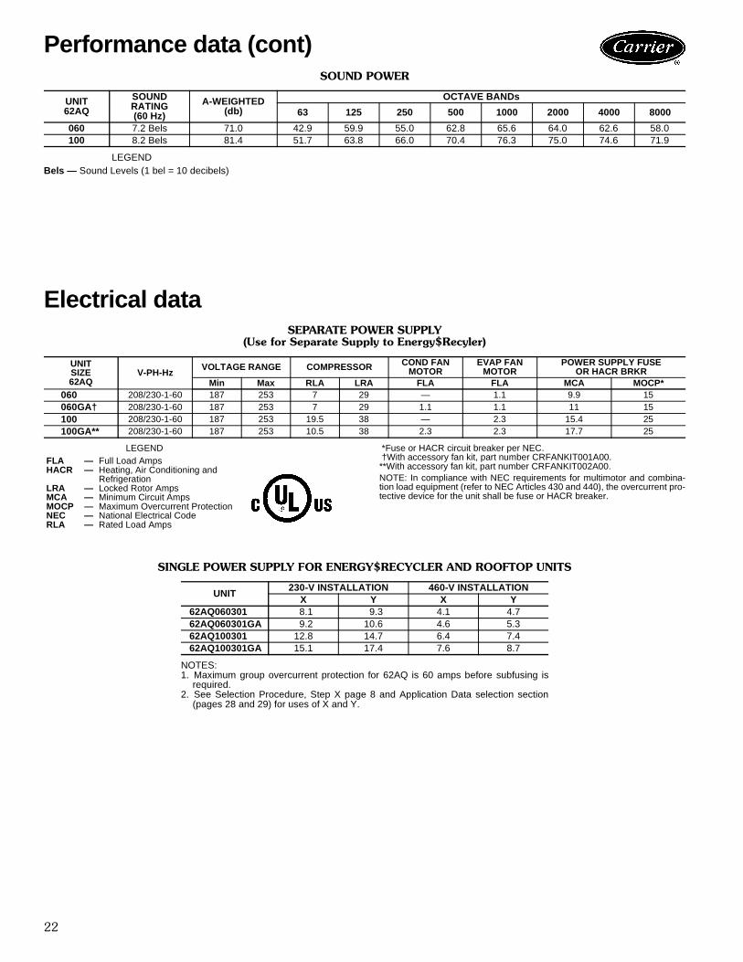
SOUND POWER
LEGENDBels — Sound Levels (1 bel = 10 decibels)
Electrical dataSEPARATE POWER SUPPLY
(Use for Separate Supply to Energy$Recyler)
LEGEND *Fuse or HACR circuit breaker per NEC. †With accessory fan kit, part number CRFANKIT001A00.**With accessory fan kit, part number CRFANKIT002A00.NOTE: In compliance with NEC requirements for multimotor and combina-tion load equipment (refer to NEC Articles 430 and 440), the overcurrent pro-tective device for the unit shall be fuse or HACR breaker.
SINGLE POWER SUPPLY FOR ENERGY$RECYCLER AND ROOFTOP UNITS
NOTES:1. Maximum group overcurrent protection for 62AQ is 60 amps before subfusing is
required.2. See Selection Procedure, Step X page 8 and Application Data selection section
(pages 28 and 29) for uses of X and Y.
UNIT62AQ
SOUNDRATING(60 Hz)
A-WEIGHTED(db)
OCTAVE BANDs
63 125 250 500 1000 2000 4000 8000
060 7.2 Bels 71.0 42.9 59.9 55.0 62.8 65.6 64.0 62.6 58.0100 8.2 Bels 81.4 51.7 63.8 66.0 70.4 76.3 75.0 74.6 71.9
UNITSIZE62AQ
V-PH-HzVOLTAGE RANGE COMPRESSOR COND FAN
MOTOREVAP FAN
MOTORPOWER SUPPLY FUSE
OR HACR BRKRMin Max RLA LRA FLA FLA MCA MOCP*
060 208/230-1-60 187 253 7 29 — 1.1 9.9 15060GA† 208/230-1-60 187 253 7 29 1.1 1.1 11 15100 208/230-1-60 187 253 19.5 38 — 2.3 15.4 25100GA** 208/230-1-60 187 253 10.5 38 2.3 2.3 17.7 25
FLA — Full Load AmpsHACR — Heating, Air Conditioning and
RefrigerationLRA — Locked Rotor AmpsMCA — Minimum Circuit AmpsMOCP — Maximum Overcurrent ProtectionNEC — National Electrical CodeRLA — Rated Load Amps
UNIT230-V INSTALLATION 460-V INSTALLATION
X Y X Y62AQ060301 8.1 9.3 4.1 4.762AQ060301GA 9.2 10.6 4.6 5.362AQ100301 12.8 14.7 6.4 7.462AQ100301GA 15.1 17.4 7.6 8.7
Performance data (cont)

23
Typical installation
EXHAUSTAIR
CONDENSER-FANDISCHARGE AIR
FRESH AIRINLET
MOUNTINGKIT
FILTERACCESS
OUTDOOR-AIRINLET
RETURN AIRBAFFLE
ROOF CURB
RETURN AIR
SUPPLY AIR
OUTDOOR AIRFLOW
INDOOR AIRFLOW

24
Typical wiring schematic — 62AQ060,100LEGEND
C — ContactorCAP — CapacitorCER — Compressor RelayCH — Crankcase HeaterCOC — Cool Changeover RelayCOH — Heat Changeover RelayCOMP — Compressor MotorCR — Cooling RelayCTD — Compressor Time DelayDB — Defrost BoardDFT — Defrost ThermostatDM — Damper MotorFU — FuseFR — Fan RelayGND — GroundHM — Humidity RelayHPS — High-Pressure SwitchHR — Heating RelayLPS — Low-Pressure SwitchLTLO — Low Temp Cooling LockoutOATC — Outdoor-Air Thermostat (Cool)OATH — Outdoor-Air Thermostat (Heat)OCR — Occupied RelayRVS — Reversing Valve SolenoidTB — Terminal BlockTRAN — Transformer
Field SpliceTerminal (Marked)Terminal (Unmarked)SpliceSplice (Marked)Factory WiringField Control WiringField Power WiringAccessory or Optional WiringTo indicate common potential only. Not to represent wiring.
NOTES1. If any of the original wire furnished must be
replaced, it must be replaced with 90° C wireor its equivalent.
2. Use copper conductors only.3. TRAN is wired for 230-v unit. If unit is to be
run with 208-v power supply, disconnectblack wire from 230-v terminal and connectto 208-v terminal.
25
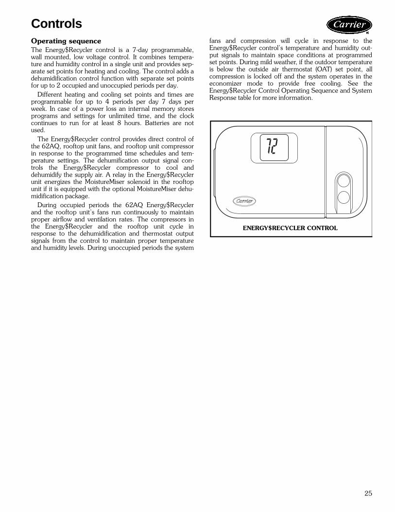
Operating sequenceThe Energy$Recycler control is a 7-day programmable,wall mounted, low voltage control. It combines tempera-ture and humidity control in a single unit and provides sep-arate set points for heating and cooling. The control adds adehumidification control function with separate set pointsfor up to 2 occupied and unoccupied periods per day.
Different heating and cooling set points and times areprogrammable for up to 4 periods per day 7 days perweek. In case of a power loss an internal memory storesprograms and settings for unlimited time, and the clockcontinues to run for at least 8 hours. Batteries are notused.
The Energy$Recycler control provides direct control ofthe 62AQ, rooftop unit fans, and rooftop unit compressorin response to the programmed time schedules and tem-perature settings. The dehumification output signal con-trols the Energy$Recycler compressor to cool anddehumidify the supply air. A relay in the Energy$Recyclerunit energizes the MoistureMiser solenoid in the rooftopunit if it is equipped with the optional MoistureMiser dehu-midification package.
During occupied periods the 62AQ Energy$Recyclerand the rooftop unit’s fans run continuously to maintainproper airflow and ventilation rates. The compressors inthe Energy$Recycler and the rooftop unit cycle inresponse to the dehumidification and thermostat outputsignals from the control to maintain proper temperatureand humidity levels. During unoccupied periods the system
fans and compression will cycle in response to theEnergy$Recycler control’s temperature and humidity out-put signals to maintain space conditions at programmedset points. During mild weather, if the outdoor temperatureis below the outside air thermostat (OAT) set point, allcompression is locked off and the system operates in theeconomizer mode to provide free cooling. See theEnergy$Recycler Control Operating Sequence and SystemResponse table for more information.
Controls
ENERGY$RECYCLER CONTROL

26
ENERGY$RECYCLER CONTROL OPERATING SEQUENCE AND SYSTEM RESPONSE
LEGEND
*The 62AQ unit is shipped with an outdoor thermostat set at 55 F which locks outmechanical cooling on the RTU and the 62AQ compressor. If this feature is notdesirable, the rooftop unit’s compressor can be allowed to run by relocating bothgray wires to the same side of the Low Temperature Lockout Thermostat (LTLO)leaving the white wire on the opposite pole, locking out only the 62AQ compressor.The LTLO is also accessible by removing the filter access panel and the door of thedamper mounting bracket.
OCCUPIEDCOOLING ER Comp ER Fans RT Comp 1 RT Comp 2 RT Fan RT Heat
Indoor Temperature Above 2nd Stage Set Point
Humidity Low & OAT Low On On On w/o MM On w/o MM On OffHumidity Low & OAT High On On On w/o MM On w/o MM On OffHumidity High & OAT Low On On On w MM On w MM On OffHumidity High & OAT High On On On w MM On w MM On Off
Indoor Temperature Between 1st and 2nd Stage Set Points
Humidity Low & OAT Low Off On Off Off On OffHumidity Low & OAT High On On On w/o MM Off On OffHumidity High & OAT Low On On On w MM Off On OffHumidity High & OAT High On On On w MM Off On Off
Indoor Temperature Below 1st Stage Set Point
Humidity Low Off On Off Off On OffHumidity High On On Off Off On Off
NOTE: OAT < 55° all compression offHEATING ER Comp ER Fans RT Comps RT Fans RT Heat
Indoor Temperature Above 1st Stage Set Point Off On Off On Off
Indoor Temperature Between 1st and 2nd Stage Set Points
OAT >Set Pt On On Off On OffOAT <Set Pt On On Off On On, 50%
Indoor Temperature Below 2nd Stage Set Point
OAT >Set Pt On On Off On On, 50%OAT <Set Pt On On Off On On, 100%
UNOCCUPIEDCOOLING ER Comp ER Fans RT Comp 1 RT Comp 2 RT Fans RT Heat
Indoor Temperature Above 2nd Stage Set Point
Humidity Low & OAT Low On On (cyc.) On w/o MM Off On (cyc.) OffHumidity Low & OAT High Off Off On w/o MM w/o MM On (cyc.) OffHumidity High & OAT Low Off Off On w MM On w MM On (cyc.) OffHumidity High & OAT High Off Off On w MM On w MM On (cyc.) Off
Indoor Temperature Between 1st and 2nd Stage Set Points
Humidity Low & OAT Low Off On (cyc.) Off Off On (cyc.) OffHumidity Low & OAT High Off Off On w/o MM Off On (cyc.) OffHumidity High & OAT Low Off Off On w MM Off On (cyc.) OffHumidity High & OAT High Off Off On w MM Off On (cyc.) Off
Indoor Temperature Below 1st Stage Set Point Off Off Off Off Off Off
NOTE: OAT < 55° all compression off*HEATING ER Comp. ER Fans RT Comps. RT Fans RT Heat
Indoor Temperature Above 1st Set Point Off Off Off Off Off
Indoor Temperature Between 1st and 2nd Stage Set Points Off Off Off On (cyc.) On, 50%
Indoor Temperature Below 2nd Stage Set Point Off Off Off On (cyc.) On, 100%
Comp — CompressorER — Energy$RecyclerMM — MoistureMiserOAT — Outdoor-Air TemperatureRT — Rooftop UnitSet Pt — Set Point
Controls (cont)

27
Dehumidification equipment and connections —The dehumidification output terminal on the Energy$Recy-cler control must be connected to the dehumidify input ter-minal on the Energy$Recycler. Additionally, if the rooftop(RTU) is equipped with optional MoistureMiser Dehumidifi-cation accessory, a relay in the Energy$Recycler controlbox (HM) energizes the MoistureMiser solenoid to activatethe enhanced dehumidification mode.
Five-minute compressor time delay — This functionprevents compressor from starting unless it has been offfor at least 5 minutes. Fifteen-minute staging timer — In multistage heatingor cooling, this timer prevents any higher stage from turn-ing on until preceding stage has been on for 15 minutes.This timer is not in effect if temperature difference isgreater than 5º F (usually due to a large change in desiredtemperature).Three-minute minimum on time — In normal opera-tion, when a stage turns on, it will not turn off for a mini-mum of 3 minutes.
Heat/cool set points (desired temperature) — Aminimum difference of 2º F is enforced between heatingand cooling desired temperatures. This is done byallowing one setting to “push” the other to maintain thisdifference. This difference is adjustable via ConfigurationOption 14.Equipment on indicators — When cooling equipment ison, a COOL icon preceded by a small triangle is displayedbelow cooling set point. While cooling equipment isdelayed by the compressor time delay, triangle will flash.The same is true for HEAT icon and its preceding trianglelocated under heating set point. Dehumidify output on indicators — TheDEHUM icon is on when the dehumidification output isenergized.Auto changeover — When auto changeover mode isselected, a change from heat to cool (or vice versa) will notoccur until an opposite mode demand has existed for10 minutes. If set point is changed, the 10-minute require-ment is deleted.Power on check — When AC power is first applied, allsegments of display are turned on for a few seconds. Fol-lowing this, temperature display indicates model/configu-ration via following 2-digit code: CP for commercialproduct.Error codes — If Energy$Recycler control cannot prop-erly read room temperature, display will indicate twodashes (--) and all outputs (except fan, if on) will turn off.E4 — If Energy$Recycler control’s internal memory fails,“E4” will be displayed. Replace Energy$Recycler control.E5 — If Energy$Recycler control cannot properlyread humidity, “E5” will be displayed. ReplaceEnergy$Recycler control.Smart recovery — With Smart Recovery selected(DIPSW1 is on), transition out of setback begins a fixedtime period before selected recovery time and graduallyadjusts room temperature so desired temperature will beachieved at selected recovery time. The fixed time period is1.5 hours. It operates in both heating and cooling.
ENERGYRECYCLERCONTROL
FOR MOISTUREMISER UNITS ONLY
62AQ
TYPICAL ENERGY$RECYCLER CONTROL WIRING
HOLD HOLIDAYMode
OFF
HEAT
COOL
AUTOCOOL
HEATFan
ON**
AUTO
CLEAN FILTERPROGRAMMING
DEHUM
OC1 UN1 OC2 UN2
TIME AM PM
Mo Tu We Th
Fr Sa Su
ENERGY$RECYCLER CONTROL LCDPOWER ON CHECK

28
Unit mounting — Accessory Energy$Recycler unitdesigned to mount directly to 3 to 12.5 ton rooftop unitsusing accessory mounting kit. No roof curb or additionalsupport required.Ductwork — None required. Unit attaches directly toreturn air opening of rooftop unit using hardware providedin accessory mounting kit package. Unit can be slab orcurb mounted and connected to competitive units usingfield-supplied mounting arrangement and ductwork.(Power and control wiring modifications required.)Airflow — Unit supply and exhaust air fans are multi-speed, direct drive centrifugal squirrel cage type with rub-ber vibration isolation mounts. Models with or without sup-ply air fan available to meet ventilation airflowrequirements. Both fans are draw through type. Adjustablesupply and exhaust air dampers provided for precise air-flow adjustment.Maximum airflow — Maximum airflow, 060 size —600 cfm, 100 size — 1,000 cfm.Minimum airflow — Minimum airflow, 060 size —300 cfm, 100 size — 600 cfm.Condensate drain — Condensate from rooftop unitdrains into lower condensate pan of Energy$Recyclerusing drain fittings supplied in installation kit (supplied withthe 62AQ unit).Minimum ambient operating temperatures
Cooling 55 FHeating –20 F
Maximum ambient operating temperaturesCooling 125 FHeating 70 F
Controls — A 7-day programmable control thermostatwith a built in humidistat is included with each unit.Control provides occupied/unoccupied signal to controlsupply and exhaust air fans and a humidity signal to con-trol compressor in Energy$Recycler unit. Relays inEnergy$Recycler unit provide control signals to the roof-top unit to control compressor operation and the dehumid-ification solenoid if the rooftop unit is equipped with theMoistureMiser option.
Selecting the 62AQ on a common power supply forall RTU sizes (except 014 230-v and 62AQ on a460-v power supply):
1. Determine the combination load rating for minimumcircuit amps (MCA) and maximum overcurrent pro-tective device (MOCP):a. Add “X” amps (found in the 62AQ nameplate and
in the Single Power Supply for Energy$Recyclerand Rooftop Units table of the Electrical Data sec-tion) to the values of MCA and MOCP for theRTU.
b. If the calculated new MOCP is nonstandard, selectthe next lowest size for the combined MOCP rat-ing. If the combined MOCP rating is less than theMCA, select the next higher size for the MOCP.
2. Determine a disconnect for the 62AQ unit:a. If the new MOCP is less than or equal to 60, a
common non-fused disconnect for the 62AQ andRTU may be used provided that:• The wire size to the 62AQ is at least 20 amps.• The disconnect size is at least equal to the dis-
connect size marked on the RTU plus, “Y”marked on the 62AQ nameplate and the SinglePower Supply for Energy$Recycler and Roof-top Units table of the Electrical Data section.
b. If the MOCP is greater than 60 amps, provideFUSED DISCONNECT for the 62AQ sized perthe 62AQ unit nameplate and the Single PowerSupply for Energy$Recycler and Rooftop Units ta-ble of the Electrical Data section.
3. Determine a disconnect for the RTU.a. If the new MOCP is less than or equal to 60, a
common non-fused disconnect sized per Step 2above may be used for the 62AQ and the RTU.
b. If the new MOCP is greater than 60, and the oldMOCP was less than or equal to 60, a FUSEDDISCONNECT no greater than 60 amps must beprovided for the RTU.
c. If the old overcurrent protection device is greaterthan 60, a non-fused disconnect sized per name-plate marking may be used for the RTU.
Selecting the 62AQ on a commmon power supplyfor all RTU 014 230-v sizes:
1. Determine the combination load rating for minimumcircuit amps (MCA) and maximum overcurrent pro-tective device (MOCP):a. Add “X” amps (found in the 62AQ nameplate and
in the Single Power Supply for Energy$Recyclerand Rooftop Units table of the Electrical Data sec-tion) to the values of MCA and MOCP for theRTU.
b. If the calculated new MOCP is nonstandard, selectthe next lowest size for the combined MOCP rat-ing. If the combined MOCP rating is less than theMCA, select the next higher size for the MOCP.
IMPORTANT: When using Energy$Recycler with3 to 12.5 ton rooftop units note the following:Energy$Recycler operates in economizer mode whenoutside air enthalpy suitable for free cooling. Do NotSpecify field or factory installed (FIOP) economizeroptions when Energy$Recycler is used.Energy$Recycler attaches to the horizontal supply/return air end of rooftop unit. Do Not Specify Factory-Installed Option (FIOP) codes “G” or “Y” that includehinged access panels when Energy$Recycler is used.
Application data
29
2. Select a FUSED DISCONNECT for the 62AQ unitsized per the 62AQ nameplate and in the SinglePower Supply for Energy$Recycler and RooftopUnits table of the Electrical Data section.
3. Determine a disconnect for the RTU.a. If installing on units without electric heat, a
FUSED DISCONNECT sized per nameplate is re-quired for the RTU.
b. If installing on units with electric heat, a non-fuseddisconnect sized per nameplate marking may beused for the RTU.
Selecting the 62AQ sizes 060 and 100 (230-v) ona common power supply with all 460-v units:
1. Determine the combination load rating for minimumcircuit amps (MCA) and maximum overcurrent pro-tective device (MOCP):a. Add “X” amps (found in the 62AQ nameplate and
in the Single Power Supply for Energy$Recyclerand Rooftop Units table of the Electrical Data sec-tion) to the values of MCA and MOCP for theRTU.
b. If the calculated new MOCP is nonstandard, selectthe next lowest size for the combined MOCP rat-ing. If the combined MOCP rating is less than theMCA, select the next higher size for the MOCP.
2. Determine a disconnect for the 62AQ unit:a. If the new MOCP is less than or equal to 30, a
common non-fused disconnect for the 62AQ andRTU may be used provided that:• The wire wize to the 62AQ is at least 10 amps.
• The disconnect size is at least equal to the dis-connect size marked on the RTU plus, “Y”marked on the 62AQ nameplate and the SinglePower Supply for Energy$Recycler and Roof-top Units table of the Electrical Data section.
b. If the MOCP is greater than 30 amps, provideFUSED DISCONNECT for the 62AQ unit sizedper the 62AQ nameplate and Single Power Sup-ply for Energy$Recycler and Rooftop Units tableof the Electrical Data section.
3. Provide a 460 to 230 stepdown transformer (partnumber HT01AH853) downstream of the 62AQ unitdisconnect.
4. Determine a disconnect for the RTU:a. If the new MOCP is less than or equal to 30, a
common non-fused disconnect sized per Step 2above may be used for the 62AQ and the RTU.
b. If the new MOCP is less than or equal to 6, a non-fused disconnect sized per nameplate markingmay be used for this unit.
c. If the new overcurrent protection device is greaterthan 60, and the old overcurrent protection devicewas less than 60, a FUSED DISCONNECT nogreater than 60 amps must be provided for thisunit.
d. If the old overcurrent protection device is greaterthan 60, a non-fused disconnect sized per name-plate marking may be used for this unit.

30
Energy$RecyclerHVAC Guide SpecificationsSize Ranges: 600 to 1,000 CfmCarrier Model Number: 62AQ
Part 1 — General1.01 SYSTEM DESCRIPTION
Outdoor rooftop, or slab-mounted, electrically con-trolled, air-to-air heat pump unit utilizing a rotarycompressor for cooling and heating duty.
1.02 QUALITY ASSURANCEA. Unit shall be designed to conform to ASHRAE 15
and in accordance with UL 1812/1995.B. Unit shall be UL listed. Unit shall be certified under
Canadian standards as a total package for safetyrequirements.
C. Insulation and adhesive shall meet NFPA 90Arequirements for flame spread and smokegeneration.
D. Unit casing shall be capable of withstanding FederalTest Method Standard No. 141 (Method 6061)500-hour salt spray test.
1.03 DELIVERY, STORAGE, AND HANDLINGUnit(s) shall be stored and handled per manufac-turer’s recommendations.
Part 2 — Products2.01 EQUIPMENT (STANDARD)
A. General:Factory-assembled, single-piece heating and coolingaccessory for use with 3 to 12.5 ton rooftop units.Contained within the unit enclosure shall be allfactory wiring, piping, controls, refrigerant charge(R-22).
B. Unit Cabinet:1. Unit cabinet shall be constructed of galvanized
steel, bonderized and coated with a bakedenamel finish on all externally exposed surfaces,with primer coated internal panels.
2. Cabinet interior shall be insulated with a mini-mum 1/2-in. thick, flexible fiberglass insulationcoated on the air side.
3. Cabinet panels shall be easily removable forservicing.
4. Holes shall be provided in the base rails for rig-ging shackles to facilitate overhead rigging.Forklift slots shall be provided to facilitatemaneuvering.
5. Units shall be factory equipped with a conden-sate drain pan made of a non-corrosive material,providing a minimum 3/4-in. connection. Thecondensate drain must be installed per manufac-turer’s installation instructions. Condensate pan
has a sloped design to conform to ASHRAEStandard 62.
6. Filters (2 in.) will be accessible through a remov-able door and will require no screw removal(tool-less).
7. One-piece top cover is standard to help preventwater and air leaks.
C. Supply and Exhaust Air Fans:1. Fans shall be of the double-inlet forward-curved
centrifugal type.2. Fan wheels shall be made from steel with a cor-
rosion resistant finish and shall be statically anddynamically balanced.
3. Bearings shall be sealed and permanently lubri-cated for longer life and lower maintenance.
D. Compressor:1. Fully hermetic rotary type with electrical over-
load protection.2. Factory rubber shock mounted vibration
isolation.E. Coils:
1. Supply and exhaust air coils shall have alumi-num plate fins mechanically bonded to internallyenhanced seamless copper tubes with all jointsbrazed.
2. Tube sheet openings shall be belled to preventtube wear.
3. Variable circulating of refrigerant for optimumheat transfer utilizing ball-type check valves.
F. Refrigerant Components:Refrigerant circuit components shall include:1. Fixed Orifice Metering Device combined with
Maximum Overcurrent Protection (MOP) typethermostatic expansion valve (TXV) to preventcompressor overloading.
2. Service gage connections on suction and dis-charge lines to charge and evacuate the system.
3. Ability to route gage hoses through unit sidepanel to eliminate air bypass during diagnosticperiods.
4. Reversing valve.5. Accumulator located in compressor suction line.
G. Filter Section:1. Standard filter section shall consist of factory-
installed low-velocity, throwaway 2-in. thickfiberglass filters of commercially available sizes.
2. Filter face velocity shall not exceed 300 fpm atnominal airflows.
H. Controls and Safeties:1. Unit Controls:
Unit shall be complete with self-contained low-voltage control circuit.
2. Standard Safeties:a. High-pressure switch.
Guide specifications

31
b. Unit shall incorporate an outdoor coildefrost system to prevent excessive frostaccumulation during heating duty, and shallbe controlled as follows:
1) Defrost shall be initiated on the basis oftime and coil temperature.
2) A 30/50/90-minute timer shall acti-vate defrost cycle only if coil tempera-ture is low enough to indicate a heavyfrost condition.
3) Defrost cycle shall terminate whendefrost thermostat is satisfied and shallhave a positive termination time of10 minutes.
4) Five-minute time delay built into thedefrost control to prevent compressorshort cycling.
I. Operating Characteristics:1. Unit shall be capable of starting and running at
125 F ambient outdoor temperature, exceedingmaximum load criteria of ARI Standard 210/240 at ±10% voltage.
2. Compressor with standard controls shall becapable of operation down to 55 F (in coolingmode) ambient outdoor temperature, and –20 F(in heating mode).
J. Electrical Requirements:All unit power wiring shall enter unit cabinet at a sin-gle factory-predrilled location.
K. Motors:1. Compressor motors shall be cooled by refriger-
ant gas passing through motor windings andshall include thermal overload protection.
2. Supply and exhaust-air fan motor shall have per-manently lubricated bearings and inherent auto-matic reset thermal overload protection.
3. Supply and Exhaust Air Damper:a. Modulating type supply air damper opens to
preset position anytime system fans areenergized to provide specified ventilationairflow.
b. Motorized spring return supply air damperautomatically closes on loss of power.
c. Capable of providing up to 100% outside airwhen matched to proper size rooftop unit.
d. Functions as economizer when outdoor airenthalpy sufficient to provide free cooling.
e. Barometric type exhaust air damper withadjustable stops to limit exhaust airflow tospecified cfm. Gravity type damper closesautomatically on loss of power or fan shutdown.
f. Supply and exhaust rain hoods with clean-able aluminum mesh filters on supply airinlet and bird screens on exhaust air outletstandard.
L. Electronic Programmable Energy$Recycler Control:1. The TSTATCCPER01B energy and recycler
control is a fully programmable thermostat witha built-in humidistat.a. Provides direct control of energy and recy-
cler control and rooftop unit fans inresponse to occupied/unoccupied outputsignals.
b. Liquid crystal display (LCD) equipment func-tion indicators display operating mode.
c. Five-minute compressor delay with overridefunctions.
d. Keypad lock feature to prevent unauthorizedchanging of program control.
e. Holiday Mode — With a single touch of abutton mode adjusts all comfort levels foroptimum efficiency while the home is unoc-cupied and restores the settings to normalupon return.
2. Other Features:a. Comfort and energy savings — Seven-day
programming with 4 temperature changesand humidity set point changes provided perday, means proper ventilation duringoccupied periods and savings throughreduced energy usage when the building isunoccupied.
b. Easy to use — Simple instructions arelocated inside the thermostat’s door.
c. Duplicate Programming — Copy the pro-grammed schedule of one day to the nextusing the copy function.
d. Override Capability — Hold function allowsthe regular schedule to be bypassed with atemporary setting.
e. Battery-Free — Non-volatile RAM chiprequires no battery backup. Retained inmemory so reprogramming is not requiredafter power loss.

Manufacturer reserves the right to discontinue, or change at any time, specifications or designs without notice and without inc urring obligations.Pg 32 Catalog No. 526-203 Printed in U.S.A. PC 111 Form 62AQ-1PD
New Replaces: New
Carrier Corporation • Syracuse, New York 13221 8-99
Book 1 1 1 4 4 4Tab 1a 1b 5a 5a 6a 6b
Book 1 1 1Tab OP1b OP2b OP3b